trouble shooting (control part). error explanation. cautions. solution map. communication wiring....
TRANSCRIPT

TROUBLE SHOOTING (Control Part)
. Error Explanation
. Cautions . Solution MAP . Communication wiring . DVMPLUS2 I/F . Indoor Power line wiring
TROUBLE SHOOTING (Control Part)
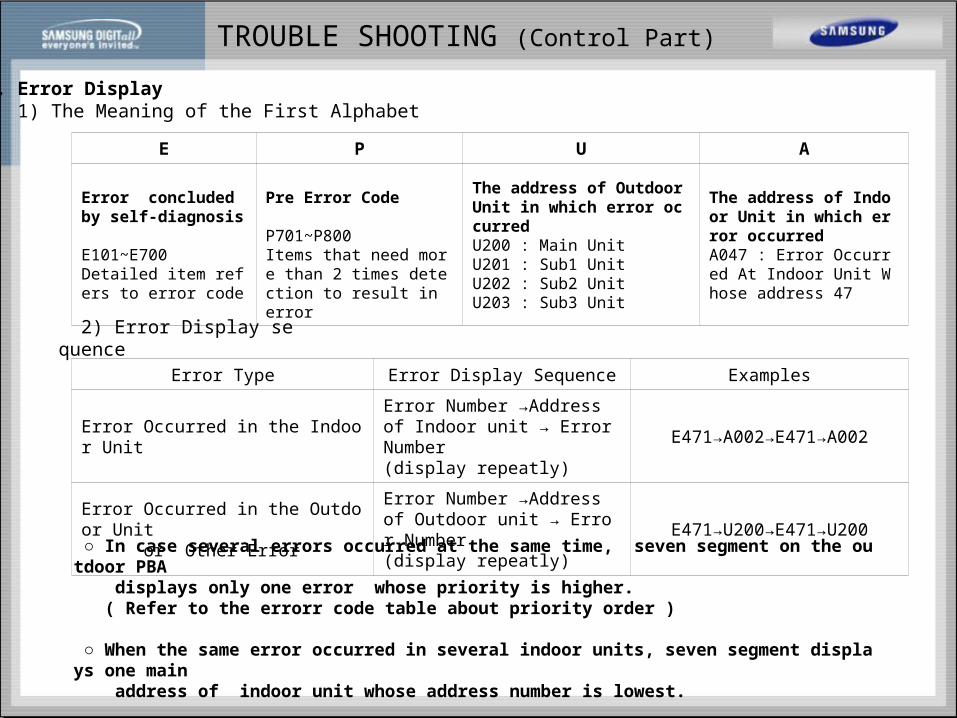
1. Error Display 1) The Meaning of the First Alphabet
E P U A
Error concluded by self-diagnosis
E101~E700Detailed item refers to error code
Pre Error Code
P701~P800 Items that need more than 2 times detection to result in error
The address of Outdoor Unit in which error occurred U200 : Main UnitU201 : Sub1 UnitU202 : Sub2 UnitU203 : Sub3 Unit
The address of Indoor Unit in which error occurred A047 : Error Occurred At Indoor Unit Whose address 47
2) Error Display sequence
Error Type Error Display Sequence Examples
Error Occurred in the Indoor UnitError Number →Address of Indoor unit → Error Number(display repeatly)
E471→A002→E471→A002
Error Occurred in the Outdoor Unit or Other Error
Error Number →Address of Outdoor unit → Error Number(display repeatly)
E471→U200→E471→U200
In case several errors occurred at the same time, seven segment on the outdoor PBA displays only one error whose priority is higher. ( Refer to the errorr code table about priority order )
When the same error occurred in several indoor units, seven segment displays one main address of indoor unit whose address number is lowest.

TROUBLE SHOOTING (Control Part)
Error Code ( Priority Order )
Error Details
E221 Short or Open of the Outdoor air temperature sensor
E251 Short or Open of the discharge temperature sensor of Digital compressor
E256 Short or Open of the discharge temperature sensor of Fixed compressor 1
E257 Short or Open of the discharge temperature sensor of Fixed compressor 2
E258 Short or Open of the discharge temperature sensor of Fixed compressor 3
E291 Short or Open of the high pressure sensor
E296 Short or Open of the low pressure sensor
E271 Short or Open of the Sump. Temperature sensor of the compressor 1
E231 Short or Open of the Cond. out temperature Sensor
E307 Short or Open of the Oil balance temperature Sensor1
E308 Short or Open of the Suction temperature sensor
E311 Short or Open of the sub cooler temperature sensor
E425 Power Reverse Phase or Phase Open
E452 Momentary power failure
E440 Stop Operating Heating mode when Outdoor temperature is over 30
E442 Stop Operating Heating charging mode when Outdoor temperature is over 15
E443 Stop Operation by Low Pressure
E431 Self diagnosis failure of Oil balance valve 1
E202 No response error after tracking is completed
E201Communication error among outdoor units and indoor units
(Pre-tracking failure or setup indoor unit number is different from the real)

TROUBLE SHOOTING (Control Part)
Error Code ( Priority Order )
Error Details
E203 Communication error between Outdoor unit’s main and sub MICOM or among outdoor Units
E407 Comp down By high pressure
E410 Comp down By low pressure
E403 Comp down By Anti-freezing control
E413 Comp down By Sump Protection Control
E554 Loading failure
E416 Comp down by compressor discharge temperature
E241 Cond. out temperature Sensor breakaway
E269 Suction temperature Sensor breakaway
E453 Error of Fan Motor’s high temperature
E454 Fan motor RPM Error
E455 Error of fan motor IPM high temperature
E458 CT over current
E457 Error of fan motor’s reverse revolution
E162 Outdoor Unit’s EEPROM Error
E560 Switch Option Set up Error
E428 Comp down by compression ratio control
E121 Short or Open of indoor unit’s air temperature sensor
E122 Indoor Unit EVA in Sensor’s Short or open
E123 Indoor Unit EVA out Sensor’s Short or open

TROUBLE SHOOTING (Control Part)
Error Code ( Priority Order )
Error Details
E154 Indoor Unit’s Fan starting Fail Error
E124 Communication error message sent from the indoor unit
E153 Indoor Unit Floating S/W error (2nd check)
P701 Indoor Unit Floating S/W error (1st check)
E152 Indoor Unit EEV Closing error (2nd check)
P702 Indoor Unit EEV Closing error (1st check)
E151 Indoor Unit EEV opening error (2nd check)
P703 Indoor Unit EEV opening error (1st check)
E128 Indoor Unit EVA in Sensor Breakaway
E129 Indoor Unit EVA Out Sensor Breakaway
E131 Indoor Unit Heater Sensor Breakaway
E265 Sump temperature Sensor of Digital Comp. or Fixed Comp.1 Breakaway
E267 Fixed Comp.2 Sump’s Temperature Sensor Breakaway
E268 Fixed Comp.3 Sump’s Temperature Sensor Breakaway
E262 Fixed Comp.1 Discharge’s Temperature Sensor Breakaway
E263 Fixed Comp.2 Discharge’s Temperature Sensor Breakaway
E264 Fixed Comp.3 Discharge’s Temperature Sensor Breakaway
E456 Fan Motor Over Current Error
E461 CT Low Current
CH Stop Operating the unit when the crank case heater is on

TROUBLE SHOOTING (Control Part)
Operation flow ofOutdoor unit
E201
E425

TROUBLE SHOOTING (Control Part)
2. Initial tracking(communicaton check) – E201 indicated if abnormal
1) When the power is on, the micom of outdoor unit check the indoor units, and transmitters Installed in the same system, which is called as tracking.
2) The left 2 sides of displays shows the address of indoor unit which the outdoor unit is trying to communicate.(0,1,2,~,47)
3) The right 2 sides of displays shows the address of indoor unit which the outdoor unit succeed in communicating.
4) Using outdoor 2 rotary switches to check the numbers of indoor unit connected with outdoor unit
5) If the total numbers of indoor unit don't match with the outdoor switches setting, the 4 segments display E201..
Main unit displays indoor unit main address in sequence from 0 to 47 Sub unit displays only outdoor unit address connected to each other like C9,CA,CB,CC,CD,CE,DF

TROUBLE SHOOTING (Control Part)
2. Reverse phase/missing phase detection - E425 indicated if abnormal
6) Letters on the 7 segment display means as the follows.
items Address (hexa)
Outdoor Main unit Main(C8H)/Sub(CCH)
Outdoor Sub unit1 Main(C9H)/Sub(CDH)
Outdoor Sub unit2 Main(CAH)/Sub(CEH)
Outdoor Sub unit3 Main(CBH)/Sub(CFH)
Indoor 0 ~ 47
Interface Module D0H
3. Compressor preheating – Ch displays
( DISCHARGE ≤ COND_Out + 2 ) and ( out air temp) ≤ 30 , for 2 minutes -> CCH ON for 2 and half hours only at first.
( DISCHARGE > COND_Out + 5 ) and ( out air temp) ≥ 32 , for 2 minutes -> CCH OFF

TROUBLE SHOOTING (Control Part)
E201: E201 Communication error in tracking indoor
Judgement Method Check by comparing set values of installed numbers of indoor units on outdoor unitPCB with actual installed numbers.
Possible Cause Communication error between indoor unit and outdoor unit, and switch setting error for installed numbers.
E202: E202 Communication error after completion of tracking
Judgement Method In case that the communication is not achieved for 2 minutes during operation between indoor and outdoor unit.
Possible Cause Communication error between indoor unit and outdoor unit, and switch setting error for installed numbers.
E203: E203 -> 200~203 Communication error between outdoors
Judgement Method In case that the communication is not achieved for 2 minutes during operation between indoor and outdoor unit.
Possible Cause - communication wire short or open-disorder of communication chip, fail of pcb power pcb

TROUBLE SHOOTING (Control Part)
E425: E425 Reverse phase detection of 3 phase power
Judgement Method - check the 3phase detection part power of outdoor unit PCB- check the color of red, white and black of the cabel for 3 phase detection part connectors.- The error is automatically reset when the phase voltage is restored in order.
Possible Cause One of the 2 phase voltages or all of them are not comingIncorrect connection of 3 phase power
E452: E452 Momentary power failure
Judgement Method In case that the communication is not achieved for 2 minutes during operation between indoor and outdoor unit.
Possible Cause Protection control of compressor, not defect
E162: E425 EEPROM error
Judgement Method - micom of indoor unit fail in communicating with the eeprom
Possible Cause Eeprom is in defect

TROUBLE SHOOTING (Control Part)
Error Code Sensor Open/Short Error Sensor type
E221 Short or Open of the Outdoor air temperature sensor 103 AT
E251Short or Open of the discharge temperature sensor of Digital compressor
204 CTB
E256Short or Open of the discharge temperature sensor of Fixed compressor 1
204 CTB
E257Short or Open of the discharge temperature sensor of Fixed compressor 2
204 CTB
E258Short or Open of the discharge temperature sensor of Fixed compressor 3
204 CTB
E231 Short or Open of the Cond. out temperature Sensor 103 AT
E307 Short or Open of the Oil balance temperature Sensor1 204 CTB
E308 Short or Open of the Suction temperature sensor 103 AT
E311 Short or Open of the sub cooler temperature sensor 103 AT
E121 Short or Open of indoor unit’s air temperature sensor 103 AT
E122 Indoor Unit EVA in Sensor’s Short or open 103 AT
E123 Indoor Unit EVA out Sensor’s Short or open 103 AT
SENSOR OPEN/SHORT ERROR

TROUBLE SHOOTING (Control Part)
Judgement Method 1. Is the connector of temperature sensor departed from PCB?2. Separate the connector from PCB and measure the resistance across both terminals.3. Is the resistance greatly out of that of the each table, 103AT, 204CTB?4. Replace sensor or PCB, measure again, and operate again.
Possible Cause Wire open or current leak of related sensor
SENSOR OPEN/SHORT ERROR
Temperature[] Resistance[kΩ]
70 2.2
60 3.0
50 4.2
40 5.8
30 8.3
20 12.1
10 18.0
0 27.3
-10 43
Temperature[] Resistance[kΩ]
130 2.6
120 3.4
100 5.8
80 10.8
60 21
25 86
20 107
10 171
0 280
-10 475
103 AT 204 CTB

TROUBLE SHOOTING (Control Part)
INDOORERRORLEDDISPLAY Status

TROUBLE SHOOTING (Control Part)
INDOORERRORLEDDISPLAY Status
TROUBLE SHOOTING (Control Part)
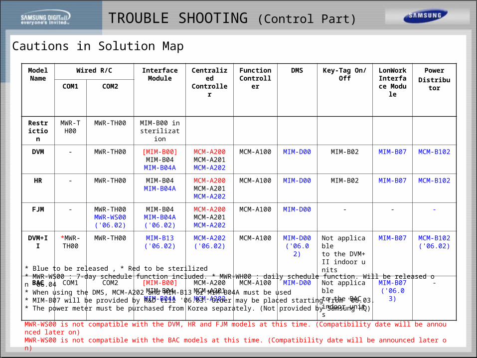
Cautions in Solution Map
Model Name
Wired R/C Interface Module
CentralizedController
Function Controller
DMS Key-Tag On/Off
LonWorkInterface Module
Power
DistributorCOM1 COM2
Restriction
MWR-TH00
MWR-TH00 MIM-B00 in sterilization
DVM - MWR-TH00 [MIM-B00]MIM-B04MIM-B04A
MCM-A200MCM-A201MCM-A202
MCM-A100 MIM-D00 MIM-B02 MIM-B07 MCM-B102
HR - MWR-TH00 MIM-B04MIM-B04A
MCM-A200MCM-A201MCM-A202
MCM-A100 MIM-D00 MIM-B02 MIM-B07 MCM-B102
FJM - MWR-TH00MWR-WS00
('06.02)
MIM-B04MIM-B04A('06.02)
MCM-A200MCM-A201MCM-A202
MCM-A100 MIM-D00 - - -
DVM+II *MWR-TH00
MWR-TH00 MIM-B13('06.02)
MCM-A202('06.02)
MCM-A100 MIM-D00('06.02)
Not applicableto the DVM+II indoor units
MIM-B07 MCM-B102('06.02)
BAC COM1 COM2 [MIM-B00]MIM-B04MIM-B04A
MCM-A200MCM-A201MCM-A202
MCM-A100 MIM-D00 Not applicableto the BAC indoor units
MIM-B07('06.03)
-
* Blue to be released , * Red to be sterilized* MWR-WS00 : 7-day schedule function included. * MWR-WH00 : daily schedule function. Will be released on '06.04* When using the DMS, MCM-A202 and MIM-B13 or MIM-B04A must be used* MIM-B07 will be provided by R&D till '06.03. Order may be placed starting from '06.03.* The power meter must be purchased from Korea separately. (Not provided by Samsung HQ) MWR-WS00 is not compatible with the DVM, HR and FJM models at this time. (Compatibility date will be announced later on)MWR-WS00 is not compatible with the BAC models at this time. (Compatibility date will be announced later on) * Remote controller model for BAC will be listed by model separately

TROUBLE SHOOTING (Control Part)
Cautions in RS-485 Communication wiring

TROUBLE SHOOTING (Control Part)
DVMPLUS2 Interface Module

TROUBLE SHOOTING (Control Part)
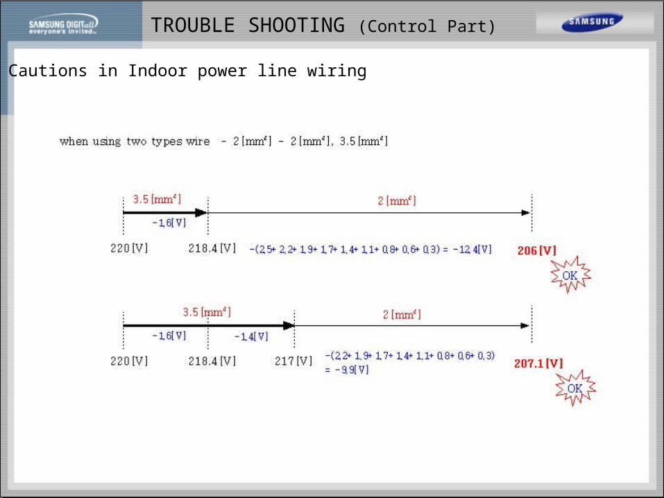
Cautions in Indoor power line wiring
(.
) [ ]k
nk k
k
coef L i
AV
1
35 6
100020
< Instrallation condition > total wire Length = 100[m], total input current i = 10[A], each indoor current 1[A], total indoor number 10[EA]
, Coef = 1.55

TROUBLE SHOOTING (Control Part)
Cautions in Indoor power line wiring
TROUBLE SHOOTING (Control Part)
Cautions in Indoor power line wiring

TROUBLE SHOOTING (Control Part)
Cautions in Indoor power line wiring
0 10 20 30 40
0
50
100
150
current
dis
tan
ce
10 20 30 40
50
100
150
current
dis
tan
ce
10 20 30 40
50
100
150
current
dis
tan
ce
2[mm2]
5.5[mm2]
3.5[mm2]
[mm2] 2 wires 3 wires
2 25 21
3.5 35 29
5.5 45 37

TROUBLE SHOOTING (Control Part)
Schmatic Diagram of DVMPLUS2
MAIN1 MAIN2 POWER