tritium inventory and recovery for a self-cooled pbli blanket
TRANSCRIPT
Fusion Engineering and Design 14 (1991) 413-425 413 North-Holland
Tritium inventory and recovery for a self-cooled Pb-Li blanket
J. Re imann
Kernforschungszentrum Karlsruhe, Institut J'm" Reaktorbauelemente, Postfach 3640, W-7500 Karlsruhe, Germany
Submitted May 1990; accepted 1 August 1990 Handling Editor: G. Casini
Tritium recovery by cold trapping in an intermediate NaK loop is considered for a self-cooled Pb-17Li blanket. The transient build-up of tritium inventory in the Pb-17Li and NaK loops is calculated for a test-plug to be used in NET. A steady-state tritium inventory of about two gramms is assessed for the blanket system including the cold traps.
Hydrogen separation and release experiments in cold traps are going to start. Calculations of the temperature, velocity and concentration distributions in cold traps point to the influence of natural convection in mesh packed cold traps. First hydrogen release experiments were performed with hydride powder and hydride crystals. Different release mechanisms were observed during recovery from NaK which suggest that tritium recovery from drained cold traps should be preferred.
1. Introduction
The blanket tritium processing system has to be optimized in order to keep the tritium inventory in the blanket system (blanket, coolant loops, tritium processing system) small and to limit the tritium loss to the environment at an allowable value. The principle tritium leakage pathway to the environment is the per- meation into the steam generator loop. This loss can be very high if a Pb-17Li/water heat exchanger is used due to the low solubility (high partial pressure) of tritium in Pb-17Li.
The concept for the self-cooled Pb-17Li blanket system includes an intermediate Na or NaK circuit between Pb-17Li and water. Tritium permeates into this intermediate loop and precipitates as tritide in a cold trap. For tritium recovery, the cold trap is decou- pied from the flow, drained and hev.ted up. The tritide is decomposed and the gaseous tritium is pumped off.
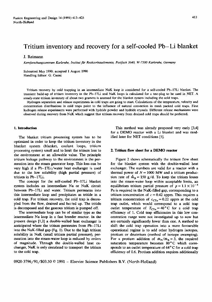
The intermediate loop can be of similar type as the intermediate Na loop in a fast breeder reactor. In the present design [1,2] a double-walled heat exchanger is anticipated where the tritium permeates from Pb-17Li into the NaK-filled gap (fig. 1). Due to the high tritium solubility in NaK (small tritium partial pressure), per- meation into the steam-water loop is reduced by orders of magnitude. Through the double-walled heat ex- changer, NaK is only circulated to transport the tritium to the cold trap.
This method was already proposed very early [3,4] for a DEMO reactor with a Li blanket and was mod- ified later for NET conditions [5].
2. Tritium f low sheet for a D E M O reactor
Figure 2 shows schematically the tritium flow sheet for the blanket system with the double-walled heat exchanger. The numbers are valid for a reactor with a thermal power of N = 1000 MW and a tritium produc- tion rate of rh B = 150 g /d . To keep the tritium losses into the steam-water loop within acceptable limits, an equilibrium tritium partial pressure of p = 1.1 × 10 -4 Pa is required in the NaK-filled gap, corresponding to a tritium concentration of c = 0.42 appm. This requires a tritium concentration of Ccro = 0.22 appm at the cold trap outlet, which would correspond to a cold trap outlet temperature of Tcr o = 4 0 ° C for a cold trap efficiency of 1. Cold trap efficiencies in this low con- centration range were not investigated up to now but are certainly significantly lower than one. A method to shift the cold trap operation into a more favourable operational regime is to add other hydrogen isotopes, protium or deuterium (method of isotope swamping). For a protium addition of rhp/rh B = 3, the required saturation temperature becomes 80°C which corre- sponds to an outlet temperature of 64 o C for a cold trap efficiency of 0.6. Protium addition requires additionally
0920-3796 /91 /$03 .50 © 1991 - Elsevier Science Publishers B.V. (Nor th -HoUand)
414 J. Reimann / Tritium inventory and recovery
Double-waLled Blanket heat exchange~ _
Pb-17Li ~ . ,
I I Na~
BLanket tritium recovery system-----.._..~=_
Blanket in ter face- - - - -
Tritium processing s y s t e r n - ~
I Tritium in Pb-17 Li J $
I Permeation through ierrltlc steel J
I i Removal in cold trap i I (precipitation as trltlde) I I I WAWIK I ~ Programme I I Recovery from cold trap i I (thermal decempesHien and vacuum punlpingl
L_ . . . . . . ,L- . . . . . . . . . T [T.t'm=ge I
Fig. 1. Principle of selected tritium recovery method for self-cooled blanket.
isotope separation at the end of the tritium system. The required value of n~p/rh a is small compared to values required for tritium recovery from other blanket types and, therefore, seems to be acceptable.
3. Tritium build-up in the NET test-plug system
3.1. Influence of the cyclic behaviour of the NET plasma
In NET, a test plug will be used for thermal-hydrau- lic experiments in a magnetic field and for demonstrat- ing tritium breeding and recovery. Due to the small plasma burn times in NET, many components of the blanket system are subjected to a cyclic thermal oper- ation which results in more severe loadings compared to a DEMO reactor.
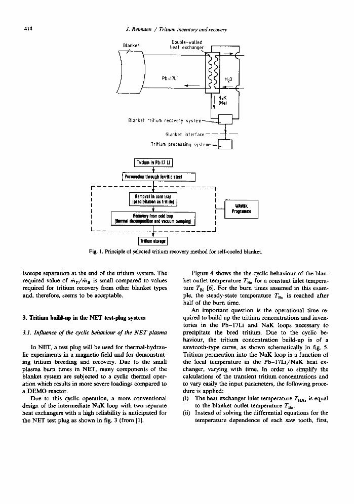
Due to this cyclic operation, a more conventional design of the intermediate NaK loop with two separate heat exchangers with a high reliability is anticipated for the NET test plug as shown in fig. 3 (from [1].
Figure 4 shows the the cyclic behaviour of the blan- ket outlet temperature TBo for a constant inlet tempera- ture TBi [6]. For the burn times assumed in this exam- ple, the steady-state temperature Tso is reached after half of the burn time.
An important question is the operational time re- quired to build up the tritium concentrations and inven- tories in the Pb-17Li and NaK loops necessary to precipitate the bred tritium. Due to the cyclic be- haviour, the tritium concentration build-up is of a sawtooth-type curve, as shown schematically in fig. 5. Tritium permeation into the NaK loop is a function of the local temperature in the P b - 1 7 L i / N a K heat ex- changer, varying with time. In order to simplify the calculations of the transient tritium concentrations and to vary easily the input parameters, the following proce- dure is applied: (i) The heat exchanger inlet temperature Tax i is equal
to the blanket outlet temperature Tao. (ii) Instead of solving the differential equations for the
temperature dependence of each saw tooth, first,

J. Reimann / Tritium inventory and recovery
double- walled heat exchanger
T=300°C ~_ blanket
~ Pb-17Li +T 1 PT = 8 Pa I IT=400°C XT=2appm
/ F / . ~ / rh=6.3x 10⁴ kg/s
T = 270°C H20
pT = 1.1 X 10 -4 Pa XT = 0.42 appm
6~ = 100 kg/s ©
NaK+T
~hydrogen (pP:? t2ua~) r
L _ ~ " ecoP/::~ :e r
I to vapour trap, I vacuum pump, I r x , ~ _ ~ etter
~ , ~ l i n g heatino ~
~j( TCT O = 6 4 ° C X / ~ . ~ . ~ XT = 0.22 appm
Fig. 2. Tritium flow sheet for DEMO reactor (Sth = 1000 i V , ~ B = 150 g/d).
415
the time tp¢rm is evaluated so as to give the same amount of permeated tritium for the steady-state temperature THx i = const as using the actual tem- perature distribution. In the calculations this time tperm is denoted t. The actual time t ' is then t ' = t / / ( t b u r n + toff ). For the example presented in fig. 4, t ' is 20~ larger than t.
(iii) A similar procedure is used to determine the mean permeation temperature Tp=~ between the inlet and outlet temperature of the heat exchanger.
3.2. Mathematical model
Figure 6 shows the tritium sources and sinks of the transient model. In the blanket, the tritium rate th a is bred. Through the heat exchanger, the tritium permea- tion rate mHx, according to the Richardson equation can be expressed as:
rhnx = (A/s)qb(pO.5 _p0.5), (1)
where A is the heat exchanger surface, s the wall thickness, *k the tritium permeability and p the tritium partial pressure. The indices I and 2 denote the Pb-17Li and NaK loops, respectively. The use of ¢q. (1) implies that the diffusion through the heat exchanger material is not the time limiting step. It can be shown that this is valid for the present case using martensitic steel and a small wall thickness. For austenitic steel and a larger wall thickness, ext. (1) can no longer be used but the time dependent diffusion in the structural material must be calculated, see Gervasim et al. [7]. For the marten- sitic steels proposed for NET, the permeability ~k is given by Forcey et al. [8]:
¢ ( k g / ( s m Pa °5 ) ) = 1.01 x 10 - 10 exp( - 5 1 8 4 / T ). (2 )
The tritium partial pressures p can be substituted by the corresponding tritium concentrations c using

416 J. Reimann / Tritium inventory and recovery
3m
l / ~ p l u g
, J
I I PbLi-Pump
, NaK H20 i 1
i i . . . . . . . P b L i / N a K H e a t Exch. ~ Na lCJH20 H e a t Exch. i i i
• ,i I f' I- E ] . . . . j ! ~ . . . . . . . . . i i
0 . - . . . . . . . . . . . . . . . . . . . . . . 6 . . . . . . . . - . . . . . . . . . . _.' T ii il
I, ............... 1 2m /" . . . . . . . . . . . . . . I 1'8 m~' ~'
I- .......... - 1 ............... ' I ~ " " " "
, . . . . . - _.~._._. ~ _ . ~ : . ~ . _ , _ u ~ . . . ~ . [ . . . . . . . . . . . j i I"1"I ~ . . . . - - i Coo,ng,ower
i i . . , ! i T r i t i u m E x t r a c t i o n System
i . i i i II II II II tl ,' Cold Traps ,! ~ i . . . . . . . . . . . . . . . . . . . . . . . . . . . . . . . . . . . . . . . . . . . . . . . . . . J
3,2 m3 PbLi ~ 1,4 m3 NaK
Fig. 3. Scheme of circuits for NET test plug.
o
I '.-
EE GJ .,,I,.-
,.~ 350 ,,,I,,-
_~ ~: fburn = 300
. D I I I
600 1200 Fig. 4. Variation of blanket outlet temperature.
1B00 time t' (s)
J. Reimann / Tritium inventory and recovery 417
tritium concentrations clc 2 NaK loop " l " j f inventories I1,12 X~ /
/
, ~ Pb-17 loop "2"
I [ ~ n + toff L
time f' Fig. 5. Schematic plot of tritium build-up.
Sievert's law
c = r p °'5, (3)
with the Sievert constant
Kl(w.fr . /Pa °'5) = 4.02 × 10 -1° e x p ( - 1 6 2 . 4 / T ) , (4)
according to Reiter et al. [9], and
K2(w.fr. /Pa °5) = 1.29 × 10 -6 exp(576/T) (5)
determined by Hubberstey [10]. The tritium flow rate precipitated in the cold trap is
P~ICT = /~112 (C2 -- ¢ 2 s ) '
where m2 is the NaK mass flow rate to the cold trap and c2s is the saturation concentration [10] at the cold trap outlet given by
c2s(w.fr) = 10.4 e x p ( - 6 2 8 6 / T ) . (7)
Permeation losses into the water loop have to be - a priori - very small so that they can be neglected.
"1" Pb-17Li "2" NaK H20
Fig. 6. Tritium flow sheet used in mathematical model.
For the tritium permeation rate through the piping between blanket and heat exchanger, it is assumed that the downstream tritium partial pressure (concentration) is negligible. Therefore,
,% = B;p °.~, (8)
where B; is considered as a parameter in the mathe- matical model.
For long distances between blanket and heat ex- changer, thp can be significant for ferritic piping material without the use of additional permeation bar- tiers. Then, rhp has to be recovered, e.g. by use of a double containment with a helium purge flow and an appropriate separation technique as foreseen for ceramic breeder blankets. The other method is to reduce ~hp to a negligible amount which can be handled by the contain- ment purification system by using austenitic steel and /o r permeation barriers on the piping, compare [1].
The time dependent tritium mass, mc, (inventory) in each loop is given by
d(mff l ) = rha dt ~ ~ - ( p ° ' 5 - p ° ' 5 ) - B ; v ° ' 5 ' (9)
d(m2c2) _ A¢ (p0.5 _pO.5) _ rh2(c2 _ C2s) ' (10) dt
where m 2 is the NaK mass and m I is the sum of the Pb-17Li mass and the modified mass of structural material (MANET) rn~
m I = m p b _ 1 7 L i -b m ~ ! , (11)
rn M = + m blanket q- m ancillary eomp. KM/KI,
(12)
with the Sievert constant for tritium dissolved in MANET given by [8]:
KM(w.fr /Pa °5) = 3.13 × 10 -7 e x p ( - 3 5 6 2 / T ) . (13)
The special form of eqs. (11) and (12) means that for inventory build-up the mass of structural material is attributed to the Pb-17Li loop. The use of eqs. (11) and (12) again imply that diffusion in the structural material is fast compared to the other processes. The different components have different temperatures. To determine the Sievert constants K M and K 1 it is assumed that half of the material is at T = 350 o C the other half at 275 o C. With eq. (12) an upper value of the tritium inventory in the structural material is calculated (conservative assess- ment).
where

418 J. Reimann / Tritium inventory and recovery
In terms of t r i t ium concentrat ions, the equat ions are given by
dc 1 rh B Ark ( - K - ~ C 2 ) BlC 1, (14)
d t m I s t a l K 1 cl
where Ba is equal to B ~ / K 1 and
de 2 A r k ( Ka ) m 2 d t s K i m 2 c 1 - - ~ 2 c 2 - ~ 2 2 ( c 2 - C 2 s ) (15)
with the boundary condi t ions c 1 = 0 and c 2 = 0 for t = 0 .
In the calculation, rh 2 is set to zero as long as c 2 < CEs. Equat ions (9-10) and (11-12), respectively, are coupled ordinary differential equations. The solutions in terms of concentra t ions are
a 2 b o - a o b 2 [ ~k2e-X~t - )kl e-x2t ] c 1= a ~ b 2 _ a 2 b l 1 + h i _ h 2
e - J k l / _ e - ~ 2 I
a c ha - - A 2 (16)
aob a - boa ~ [ h2e-X" _ )~le-x2 ' ] c 2 = a~b2_ a2ba 1 4 -~1--_~22 j
e - h i t _ e - ~ 2 t
b 0 ha _ h2 , (17)
where
ha, 2 = - 0 . 5 ( a ~ + b2) + ( ( a ~ b 2 ) 2 / 4 - a~b 2 - a2ba) 2,
(18)
Table 1 Characteristic values for the NET test plug
plasma burn time plasma off time permeation time per cycle actual time blanket tritium production rate blanket outlet temperature (t ---, o0) blanket inlet temperature NaK = heat exch. inlet temp. NaK-heat exch. outlet temp. mean permeation temperature permeation factor
Sievert constant K 1 for T 1 = 313°C
Sievert c o n s t a n t K 2 for T 2 = 277.5 o C
Sievert c o n s t a n t K M for T = 313°C
cold trap mass flow rate cold trap outlet saturation concentration
Pb-17Li/NaK heat exchanger surface heat exchanger wall thickness mass of NaK mass of Pb-17Li in blanket in ancillary components in heat exchanger mass of structural material (MANET) in blanket in ancillary components in heat exchanger
tburn = 8 0 0 S
lot t = 200 S
tperm = 7 2 0 S
t ' = 1.38t th B = 0.75 g / d 7"1o = 350 ° C Tl i = 275 o C T2i = 2 4 0 ° C
T2o= 315°C T~r m = 298 o C #,=1.15X10 -4
(kg/s mPa °'s) K 1 = 3.05 x 10 -1°
w.fr./Pa °-s K2 = 3.44×10 -6
w.fr./Pa °.5 g M = 6 . 1 1 × 1 0 - 1 °
w.fr./Pa °.5 rh 2 = 0.1 kg/s CCT o = 1 .05 × 10 -- 7
w.fr. A = 2 5 m 2 s =2.9 mm m2 =1.04× 10³ kg m 1 = 2850 kg m I = 15250 kg m 1 = 3800 kg
m w =1780 kg m M = 585 kg mM= 580 kg
with
a o = rh n / m l ; p a I = A r k / ( s m l K 1 ),
a I = - ( a I + B1); a2 = a 2 K 1 / K 2 ,
b o = C z s r h 2 / / m 2 , bi = a l m l / m 2 ;
b 2 = a l ( m l / m 2 ) ( K 1 / K 2 ) - t h 2 / m 2.
The steady-state (t--* 0o) concent ra t ions are given by the fract ions left of the parentheses.
3. 3. Results
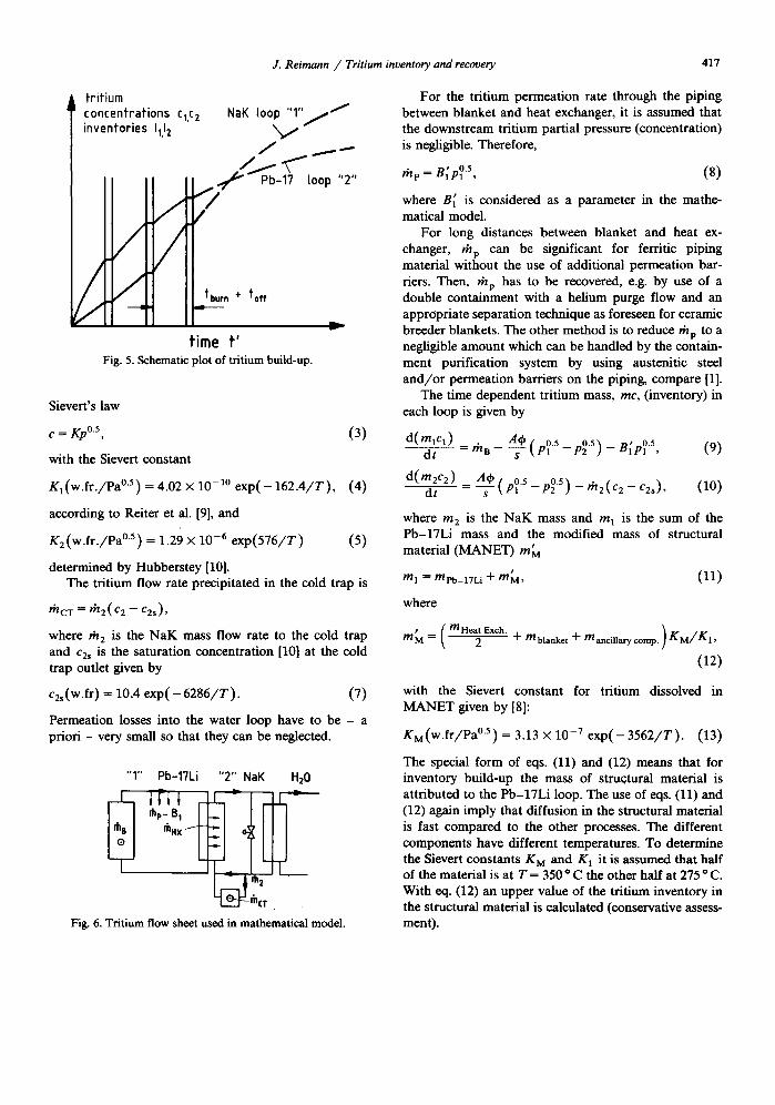
The calculations were per formed for the pa ramete r values given in table 1. Figure 7 shows the results for no permeat ion losses th rough the piping ( B 1 = 0). The con- centra t ions are normal ized by the corresponding values for t ~ oo. Steady-state condi t ions are reached after about 6 days of full power reactor operat ion. After this t ime period, the total t r i t ium inventory in the loops
wi thout the t r i t ium inventory in the cold trap is about 1.2 g. For this calculat ion the t r i t ium removal system was opera t ing f rom the start and t r i t ium was removed in the cold t rap as soon as the N a K loop concent ra t ion c 2 was larger than the cold t rap outlet sa tura t ion con- cent ra t ion CcTo-
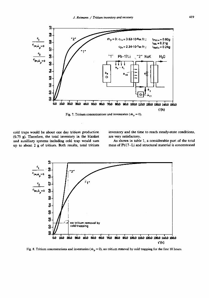
To shor ten the per iod of t ime to reach steady-state t r i t ium inventory in the loops, t r i t ium removal should only start when the t r i t ium concent ra t ion in the N a K reaches the s teady-state value ob ta ined with cold t rap opera t ion (c 2 = 1.92 × 10 -7 w.fr). The per iod of t ime to reach this value is abou t 18 hours of full power reactor opera t ion as shown in fig. 8. Then, some full power reactor opera t ion days are required to test the t r i t ium removal and recovery system. First exper iments on hy- drogen recovery f rom cold t raps [11] showed tha t at least one recovery cycle per day is feasible. Using one cold trap for t r i t ium removal and a second one for t r i t ium recovery the addi t iona l t r i t ium inventory in the
J. Reimann / Tritium inventory and recovery 419
Clm,~pffi 0
C2
C~.,Ap= 0
=01 0
" 2 " ~ ~ C l . = 3.63-10-ew.fr.; IpbL,. = 0.80g ~ IUo=O.21g
/ / C2" : 2'34"lO-7w'fr-; INaK. = 0.24g /
/ / "1" Pb-17Li .."2" NaK HzO
t'(h) Fig. 7. Tritium concentrations and inventories (rap = O).
cold traps would be about one day trit ium production (0.75 g). Therefore, the total inventory in the blanket and auxilliary systems including cold trap would sum up to about 2 g of tritium. Both results, total tri t ium
inventory and the time to reach steady-state conditions, are very satisfactory.
As shown in table 1, a considerable part of the total mass of Pb17-Li and structural material is concentrated
c: t S - # 2 ~ Clm,,np= 0
e2=,~p=O _
" ~ t-~, ,cold i r a p p ; g OlD 10.0:00.0 80.0 40.0 ~ 0 ~ 70.0 ~ ~ 100.0/10.0 J~0.0130.0 140.01J50,0
t'(h)
Fig. 8. Tritium concentrations and inventories (rhp = 0), no tritium removal by cold trapping for the first 18 hours.

420 J. Reimann / Tritium inventory and recovery
in the piping and other components between the blan- ket and the Pb-17Li /NaK heat exchanger. Due to the high tritium partial pressure (for B1 = 0: p = 7670 Pa), permeation losses through the piping into the reactor containment have to be considered. For the previously presented results of the calculations for B t = 0 it was assumed that a perfect permeation barrier existed at the outside of the piping. (For a perfect permeation barrier at the inside, the term ma~c.comp" in eq. (12) would be zero). If neither permeation barrier is feasible, an ad- ditional containment (double tube containment) is re- quired. Then, the permeated tritium has to be removed in the gap by e.g. a helium gas purge stream. This requires an additional tritium removal system as fore- seen for ceramic breeder blankets. The disadvantage of needing an additional tritium reprocessing system might be compensated by the fact that the tritium inventory in the loops is decreased. Figure 9 shows the result for the assumption that the tritium permeation into the double containment is as large as that one through the Pb- 17Li/NaK heat exchanger and that the cold trap is in operation from the beginning. Steady-state conditions are already after about two days and the total tritium inventory (without cold traps) reduces to about 0.7 g. This improvement compared to the case B 1 = 0 does not compensate the increase of technical complexity. Therefore, the use of permeation barriers should be anticipated. Presently, numerous investigations are being performed to develop permeation barriers because this
is a general problem of all blanket concepts and consid- erable progress has been achieved recently, compare Gervasini et al. [7] and Forcey et al. [12]. Therefore, the above assumption of B 1 = 0 appears to be acceptable especially if the barriers are provided at the outer tube surface where an oxidizing atmosphere exists.
The tritium permeation loss into the water loop becomes 3 × 10 -5 g / d = 0.3 C i /d for a ferritic heat exchanger with a surface area of 7 m 2 and a mean permeation temperature of 217°C. Neither isotope swamping (protium addition) was applied nor permea- tion barriers were assumed in the present assessments. If this tritium loss is too high, a small amount of protium can be permeated into the NaK flow to the cold trap and both the tritium inventory in the NaK loop and the permeation loss can be reduced signifi- cantly.
4. Tritium recovery
4.1. Tritium separation
Tritium permeation through the Pb-17Li /NaK heat exchanger is presently not considered as a critical issue. Even an impediment of permeation by surface layers which would result in a tritium concentration higher by a factor of ten (permeation barrier factor of ten) in the
Cl~,~p= 0
C2
c2=,~p= o
~ "2"
~" "1"
~_ rhp= rhHx:¢l.= 1.82.10-Sw.fr.; IpbLi.= 0.40g IM.= 0.11g
~ - C2®= 1.71-10-7w.fr.; INaK. = 0.18cJ
t '(h) Fig. 9. Tritium concentrations and inventories (Ihp = rh HX )"

J. Reimann / Tritium inventory and recovery 421
Pb-17Li loop would only double the total tritium in- ventory in the loops. This would be still a favourable value. It is well known that at the NaK/wa l l interface permeation barriers due to oxide layers do not build up because of the high chemical potential of NaK towards oxygen. In corrosion experiments, oxide layers were not observed at the Pb-17Li /wal l interface either [13]. Therefore, our present investigations concentrate not on permeation but on the hydrogen separation and release kinetics in NaK cold traps. In the experiments, tritium is simulated by protium. The term hydrogen, therefore, refers always to protium.
Cold traps have been widely used in liquid metal loops of fast breeder reactors for purification from oxygen and hydrogen. Basically, a cold trap is a coun- ter-currently cooled flow duct which contains a packing of wire mesh. The liquid metal alloy enters the cold trap at a temperature where the impurity concentration is below its saturation concentration c s. Due to cooling, the saturation concentration is reached after a certain flow length and precipitation as oxide and hydride crystals takes place further downstream on the large surface of the packing and the cylinder wall.
In previous applications, cold traps mostly plugged much earlier than expected. However, the precise knowledge of the precipitation process was not an ur- gent need because the loaded cold trap was discarded as waste. Only recently, results from more detailed investi- gations were published [14,15]. For the design of a fusion reactor blanket cold trap, more knowledge is required on the local precipitation for small tritium concentrations, and on the tritium release from cold traps with small inventories (loadings).
A test loop for hydrogen separation [16] has been built up. At present, this loop is taken into operation. Calculations were performed in order to determine the temperature (T)l velocity (v), concentration (c), and deposition rate (S) distributions in the experimental cold trap (ECT) to be used in future experiments. The important question is, whether hydride precipitation is influenced by the occurrence of natural convection. The calculations were carried out considering Na a liquid metal. In future calculations, the properties of NaK will be used.
The ECT (see fig. 10) consists of a wire mesh packed cylinder with a cooling zone (countercurrently flowing
liqu
p
p r __. ,~ R
r
lOO ~
X -
o 4 - - - p,.
A
l ° [ ]
T1 V l C !
To : Consf Vo = Const Co - Const
1
Tw - T~
To - T1
Fig. 10. Experimental cold trap and assumptions for mathematical model.
422 J. Reimann / Tritium inoentory and recooery
[..4
15
o <5 V ,
-I.0 -o.r, (~.r, ,.0 a. l lpwal~l Inl(~'l. H o w r
co
~ to ( <5-
o <5' -¢6
¢:' 6 "
oo <5
o
- I . 0
f
- 0 . ~ ()..e~
<5
o o
d
c5
o d
o <5
o <5
1.0
...; ,,/ , I - ]
/ t~P
o r- . o , _ ~
d -o "
- o d
o d~ ¢'t ' g
o - d
, r ~ I
- I . t ) -o .r , 0.r~ t .0 -I .c) -0 . r , 0.:, I.o
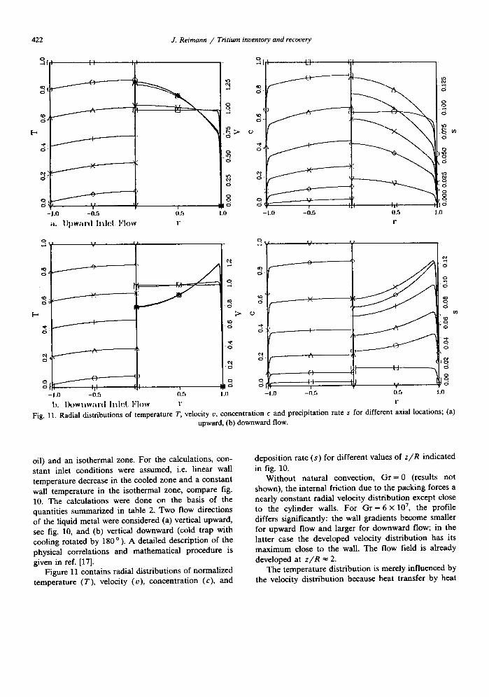
b. l)owllwal"d h l l d . Flow t" r Fig. 11. Radial distributions of temperature T, velocity o, concentration c and precipitation rate s for different axial locations; (a)
upward, (b) downward flow.
oil) and an isothermal zone. For the calculations, con- stant inlet conditions were assumed, i.e. linear wall temperature decrease in the cooled zone and a constant wall temperature in the isothermal zone, compare fig. 10. The calculations were done on the basis of the quantities summarized in table 2. Two flow directions of the liquid metal were considered (a) vertical upward, see fig. 10, and (b) vertical downward (cold trap with cooling rotated by 180 ° ). A detailed description of the physical correlations and mathematical procedure is given in ref. [17].
Figure 11 contains radial distributions of normalized temperature (T), velocity (o), concentration (c), and
deposition rate (s) for different values of z / R indicated
in fig. 10. Without natural convection, G r = 0 (results not
shown), the internal friction due to the packing forces a nearly constant radial velocity distribution except close to the cylinder walls. For Gr = 6 x 10⁷, the profile differs significantly: the wall gradients become smaller for upward flow and larger for downward flow; in the latter case the developed velocity distribution has its maximum close to the wall. The flow field is already
developed at z / R ~ 2. The temperature distribution is merely influenced by
the velocity distribution because heat transfer by heat

J. Reimann / Tritium inventory and recovery 423
Table 2 Characteristic quantities
density p = 909 kg/m 3 kinematic viscosity v = 5.45 x 10⁻⁶ mE/s thermal diffusivity ~ = 6.81 x 10 -4 m2//s
thermal expansion a = 2.42 x 10⁻⁴ K - 1
hydr. diffusivity in sodium D = 1.15 X 10- s m2/s inlet temperature T O = 7",0 = 483 K outlet wall temperature T,] = 433 K inlet velocity i, o = 4 mm/s inlet concentration (c o = cs(To) = 1.6 wppm Reynolds number Re = ooR/v = 360 Grashof number Gr = agR3AT/v = 6 X 10 7
Prandtl number Pr = ~,/r = 0.008 Schmidt numbe Sc = v / D = 47.4
conduction is the dominating process (small Prandtl number). For the local deposition rate, it was assumed that diffusion is the dominating mechanism. The radial deposition rate is then of similar type as the velocity distribution and, therefore, is influenced by natural convection.
These numerical results show that natural convection effects are not limited to unpacked cylinders but also influence significantly radial velocity and deposition distributions in packed cylinders. In order to assess the accuracy, of different mass transfer models, detailed experimental and theoretical data are needed.
These calculations are important in combinat ion with the experiments for the modelling of mass transfer.
4.2. Tritium release
After loading the cold trap with hydrides, the drained cold trap will be transferred to a glove box to determine the local distribution and crystal morphology of the hydrides. Hydrogen recovery by thermal decomposit ion will be performed by heating up the hydride covered cold trap inserts in an electrically heated vessel and pumping the hydrogen gas to a gasometer where the release rate is measured. This test apparatus is in oper- ation and was used for experiments where the cold trap hydride crystals were simulated in different ways [11]:
In a first step, commercial fine Nai l -powder , sus- pended in a b,asket, was thermally decomposed. In a part of the experiments, Na20-powder was added. The release coefficient k was defined as
rh = k ( m o - m ) ' , (16)
where rh is the hydrogen mass flow rate, m 0 the initial mass of hydrogen in the reaction vessel, m the total
mass of released hydrogen at time t, and the exponent n characterizes the reaction order. The release coefficient was evaluated assuming a value n = 1. No influence of oxygen on the release rate was found, the results agreed well with previous results [18]. Figure 12 contains the mean curve of the experiments in an Arrhenius plot.
The specific surface of the Na i l -powder is expected to be not relevant for Nai l -crys ta ls in cold traps. There- fore, in a second step, Nai l -crysta ls were generated in a Na filled vessel where hydrogen was absorbed at the top of the Na interface and hydride crystals precipitated at the cooled bot tom of the vessel. For hydrogen recovery, the cooling was removed and an additional heating was used at the bottom.
This experimental set-up was also used with N a K instead of Na. Figure 12 contains also these results. For N a i l crystals the release coefficient is significantly lower than for Na i l -powder due to the considerably smaller specific surface of the crystals as observed with a micro- scope. The release mechanism was clearly dominated by hydrogen bubble formation and transport in the Na pool.
~00 350 T(°C) 300 280
k(s"
10 "~
10-3
10-~
10-s
I I
\ \
\ \
System
NaK-H Na-H
\
Resulfs
mOINaK)H-crystalsoNaK ---NaH-povder(,NazO-powd~r} ..... NaH-crystals.Na
\ \ .
1.5 1.6 1.7 10=/T
Fig. 12. Hydrogen release coefficient k.
\
"xU ~ ~ \ ~NaH-povder ~. ~ ~ _ \ log k=6.12-5633/'1' \ \
'~. r ~ , / ' ~ hydrogen bubbling ~ \ '~.0 ~ n o hydrogen bubbffng \

424 J. Reimann / Tritium inventory and recovery
The release coefficient for NaK hydride crystals is considerably larger than for Nail-crystals as long as release by hydrogen bubble formation prevails. This tendency is expected due to the higher saturation pres- sure of NaK hydride compared to Nai l for the same temperature. However, decomposition of hydride without hydrogen bubble formation in the NaK pool occurs at low release rates. Then, the release coefficient becomes considerably lower because diffusion and de- sorption mechanisms at the free surface become rate determining.
The practical consequence from these preliminary experiments is to drain the cold trap from NaK before heating up the cold trap. Assuming the same release coefficient as for hydrogen bubbling, 99% of the tritium would be released at a temperature of 400 °C in about three hours. This would enable two regeneration cycles per day, which would result in a tritium inventory in two NET cold traps (batch operation) of about 0.5 tritium productions per day that is 0.375 g. However, corresponding experiments are required with hydride loaded cold traps from hydrogen separation experi- ments.
5. Requirements for processing tritium recovered from the self-cooled Pb-17Li blanket: the Blanket Interface
The aim of the blanket tritium recovery system (BTRS) is to recover the tritium bred in the blanket. However, not only gaseous tritium may leave the BTRS but, depending on the blanket concept, also protium, tritium cartier gas and various impurities. An additional tritium processing system (TPS) is required to obtain pure T 2 gas, compare fig. 1. The boundary between these two processing systems was called Blanket Inter- face [19].
For ceramic breeders, tritium is very diluted in a He stream, and the protium concentration is higher by several orders of magnitude due to isotope swamping in order to obtain a small tritium inventory in the breeder. For water-cooled Pb-17Li blankets, tritium purification of the water loop is required. For self-cooled Li blan- kets various impurities are carried over into the TRS [20].
The specific features of the BTRS for the self-cooled Pb-17Li blanket are: - No carrier gas is required for tritium recovery (small
volume flow rates have to be processed). - T r i t i u m is recovered in gaseous form (HT) (no
processing of HTO required).
- The blanket tritium recovery system (BTRS) is dis- connected from the neutron field (no loading of the BTRS with radionuclides besides tritium).
- The BTRS is disconnected from the Pb-17Li loop (much lower corrosion in Na or NaK which results in very low impurity levels).
Impurity source terms in the intermediate loop were estimated and the consequences on the BTRS were discussed [21]. The result was that besides protium and tritium no significant amounts of other species leave the BTRS. This flow can then be processed in the system required for fuel clean up without any significant mod- ifications.
6. Concluding remarks
The selected tritium recovery method offers several conceptional advantages: (i) the technique has been principally proved already
in other areas (LMFBR), (ii) enables a small tritium inventory in the total blan-
ket system, and (iii) leads to minimum requirements for the subsequent
tritium processing system. Experimental and theoretical work is needed to prove the attractiveness of the concept. Hydride precipitation and decomposition kinetics have to be investigated un- der blanket-relevant operating conditions, characterized by: low tritium concentration range during tritide pre- cipitation, low cold trap loading before tritide decom- position, proper operation of tritium recovery system after numerous regeneration cycles. The results from these investigations might lead to a cold trap design different from previous ones used in other areas. In a further step, the tritium permeation from Pb-17Li through the heat exchanger into the NaK has to be investigated.
References
[1] S. Malang et al., Self-cooled blanket concepts using Pb- 17Li as liquid breeder and coolant, Fusion Engrg. Des. 14 (1991) 373-399, in this issue.
[2] S. Malang, K. Arheidt, I. Barleon, H.u. Borgstedt, V. Casal, U. Fischer, W. Ling, J. Reimann, K. Rust, and G. Schmidt, Self-cooled liquid-metal blanket concept, Fusion Technology 14, No. 3 (1988) 1343-1356.
[3] J.S. Watson, An evaluation of the methods for recovering tritium from the blankets or cooling systems of fusion reactors, ORNL-TM-3794 (1972).

J. Reimann / Tritium inventory and recovery 425
[4] K. Natesan and D.L. Smith, Effectiveness of tritium re- moval from CTR lithium blankets by cold trapping sec- ondary liquid metals Na, K, and NaK, Nuclear Technol- ogy 22 (1974).
[5] J. Reimann and S. Malang, A study of tritium separation from LiPb by permeation into Na or NaK and cold trapping, Kernforschungszentrnm Karlsrnhe, KfK-4105 (Oct. 1986).
[6] C. Giinther, personal communication. [7] G. Gervasini and F. Reiter, Tritium inventory and per-
meation in separately cooled liquid breeder blankets. J. Nucl. Mater. 168 (1989) 304-311.
[8] K.S. Forcey et al., Hydrogen transport and solubility in 316L and 1.4914 steels for fusion reactor applications, J. Nucl. Mater. 160 (1988) 117-124.
[9] F. Reiter, J. Camposilvan, G. Gervasini and R. Rota, Interaction of hydrogen isotopes with the liquid eutectic alloy 17Li83Pb, Proc. 14th SOFT, Avignon (1986) 1185- 1190.
[10] P. Hubberstey, Solutions of hydrogen in alkali metals, in: Handbook of Thermodynamic and Transport Properties of Alkali Metals, ed. R.W. Ohse (Blackwell Scientific Publications, 1984).
[11] J. Reimann and H. John, Tritium separation from Pb-17Li by permeation into NaK and cold trapping: First experi- ments on hydrogen recovery, Fourth Int. Conf. Liquid Metal Eng. and Techn., Avignon, France, OCt. 17-21, Vol. 3, (1988), 621/1-8.
[12] K.S. Forcey et al., The use of aluminising on 316L austenitic and 1.4914 martensitic steels for the reduction of tritium leakage from the NET Blanket, J. Nucl. Mater. 161 (1989) 108-116.
[13] H.U. Borgstedt, Personal communication.
[14] C. Saint Martin, C. Latg6, P. Michaille, and L. Lagu¢rie, Mechanism and kinetics of crystallization of sodium hy- dride in cold traps, Fourth Int. Conf. Liquid Metal Eng. and Techn., Avignon, France, Oct. 17-21, Vol. 3 (1988) 617/1-10.
[15] M. Latg6, Mine Lagrande, M. Suraniti, and M. Ricard, Development of a new cold trap concept for fast breeder reactors, Fourth Int. Conf. Liquid Metal Eng. and Techn., Avignon, France, Oct. 17-21, Vol. 3 (1988) 610/1-12.
[16] J. Reimann, H. John, and S. Malang, Tritium separation and recovery from NaK by cold traps: Results on hydro- gen recovery from Na and NaK; Fusion Technology 1988 (Elsevier Science Publishers, 1989) 1306-1311.
[17] L. Biihler and J. Reimann, Mass transfer at mixed convec- tion in vertical cylinders; VII Symp. Heat & Mass Trans- fer, Jadwison, Poland, Oct. 23-26 (1989) 57-69.
[18] R.S. Fidler and A.C. Whittingham, A comparison of alternative methods for in-situ sodium cold trap regenera- tion, Liquid Metal Eng. and Techn., BNES, London (1984) 413-417.
[19] D.K. Sze, P. Finn, R. Clemmer, J. Anderson, J. Bartlit, Y. Naruse and H. Yoshida, The role of a blanket tritium system on the fusion fuel cycle, Fus. Eng. and Design 10 (1989) 203-207.
[20] R.G. Clemmer, P.A. Finn, L.R. Greenwood, T.L. Grimm, D.K. Sze, J.R. Bartlit, J.L. Anderson, H. Yoshida, and Y, Narnse, The requirements for processing tritium recovered from liquid lithium blankets: the Blanket interface, ANL/FFP/TM-217 (March 1988).
[21] J. Reimann, S. Malang, and H.U. Borgstedt, Require- ments for tritium processing recovered from a self-cooled Pb-17Li blanket, to be published.