triol ak06 - triol corpprotection degree of vsd cabinet is nema 4 as per nema 250-2008. variable...
TRANSCRIPT

e v e r y t h i n g n e w e m e r g e s n o w
TRIOL AK06VARIABLE SPEED DRIVE
FOR ESP APPLICATIONS
S o f t w a r e v e r s i o n o f a U M K A - 0 3 c o n t r o l l e r i s 3 1 . 9 6 .
A T . 6 5 4 2 2 6 . 2 4 2 - 3 2 O M

2А Т . 6 5 4 2 2 6 . 2 4 2 - 3 2 O M
Dear Customer!
Thank you for purchasing the equipment produced by Triol Corporation. We are sure that our Variable Speed Drive (VSD) of Electrical Submersible Pumps (ESP) for crude oil production equipped with ESM and PMM series motors and a frequency converter of Triol AK06 series (hereafter referred to as Vari-able Speed Drive) will be operated effectively and will make a profit for you.
We also want to remind you that the VSD purchased by you is a complex electrical device and its inexpert and unqualified operation may cause breakdown of the drive and submersible equipment. That’s why we strongly recommend you to study carefully the Operating Manual before starting the operation of the VSD and to pay attention to the safety precautions (Section 2.1.1).
A set of documents supplied with the VSD consists of the following:• Operating Manual;• Datasheet.The present Operating Manual describes technical data, design, service, rules of operation and mainte-
nance of the VSD produced by Triol Corporation.
Abbreviations used in the text of the document are as follows:
ARC – Automatic reclosing;ACS – Automated control system;TUL – Trip on underload;OLP – Overload protection;VSDC – Variable Speed Drive controller;OCP – Overcurrent protection;TS – Tubing string;ESM – Electrical submersible motor; PMM – Permanent magnet motor;VSD – Variable Speed Drive;TMS (DME) – Telemetering system (Downhole Measuring Equipment);ACVOT – AC voltage oil transformer;ESPU – Electric submersible pumping unit;ESP – Electric submersible pump;QF1, QF2 – Circuit breaker for power circuits;QF3 – Circuit breaker for control circuits;QF4 – Circuit breaker for standby power supply; QF5 – Circuit breaker for fans;QF6 – Circuit breaker for telemetering system;APF – Active Power Filter.

3T R I O L C O R P O R A T I O N w w w . t r i o l c o r p . c o m
Operating ManualContents
Contents
1. Description and operation .................................................................................... 5
1.1. Variable Speed Drive function .......................................................................... 51.1.1. Variable Speed Driver symbol structure ..................................................... 6
1.2. Variable Speed Drive specification .................................................................... 71.3. VSD configuration ......................................................................................... 8
1.3.1. VSD structure ...................................................................................... 81.3.2. Function of VSD components................................................................. 111.3.3. APF module construction ..................................................................... 12
1.4. VSD design and operation ............................................................................. 141.4.1. VSD capabilities ................................................................................. 141.4.2. VSD operating modes .......................................................................... 16
1.6. Packaging and marking ................................................................................ 20
2. Intended use ................................................................................................... 21
2.1. Preparation of VSD for use ............................................................................ 212.1.1. Safety precautions ............................................................................. 212.1.2. ESPU starting preparation .................................................................... 222.1.3. VSD starting procedure ........................................................................ 272.1.4. VSD setup for manual mode of operation .................................................. 272.1.5. VSD setup for automatic mode of operation .............................................. 302.1.6. VSD setup for mode of operation by “AC L” algorithm .................................. 312.1.7. VSD setup for mode of operation by “VC of DCM without feedback” algorithm .. 32
2.2. Variable Speed Drive operation ...................................................................... 332.2.1. Protection setting procedure ................................................................. 332.2.2. Features conclusion to mode and elimination of complications ...................... 35
2.2.2.1. Features start and conclusion to mode, provided a complete set of ESP submers-ible telemetry ...................................................................................... 352.2.2.2. Elimination complications.............................................................. 36
2.2.3. VSD switching-off procedure ................................................................. 372.2.4. Troubleshooting in Variable Speed Drives Triol AK06 ................................... 37
2.2.4.1. Checking operability at no load ....................................................... 382.2.4.2. Troubleshooting at ESM startup and troubleshooting algorithms ................. 382.2.3.3. Checking VSD with shorted output circuit; checking IGBT modules .............. 462.2.3.4. Faults and alarm conditions ........................................................... 46
2.3. Operator interface. Description of UMKA-03 controller and its operation ................. 472.3.1. General ............................................................................................ 472.3.2. Description of operator interface ........................................................... 49
2.3.2.1. Entering the menu ...................................................................... 502.3.2.2. Status display mode .................................................................... 51
2.3.3. Description of the UMKA-03 controller menu ............................................ 522.3.3.1. UMKA-03 controller first-level menu ................................................. 522.3.3.2. “Commissioning” first-level menu .................................................... 542.3.3.3. “ESM actual parameters” first-level menu ........................................... 562.3.3.4. “VSD actual parameters” first-level menu ........................................... 572.3.3.5. “Actual input parameters” first-level menu ........................................... 582.3.3.6. “Modes of operation” first-level menu................................................ 592.3.3.7. “Modes of start” first-level menu ..................................................... 682.3.3.8. “Drive settings” first-level menu ...................................................... 722.3.3.9. “Protections” first-level menu ......................................................... 742.3.3.10. “Downhole measure equipment” first-level menu (Telemetry) ................... 832.3.3.11. “Installation parameters” first-level menu .......................................... 89

4А Т . 6 5 4 2 2 6 . 2 4 2 - 3 2 O M
2.3.3.12. “Calc.of step-up transf.tap voltage” first-level menu ............................. 902.3.3.13. “System” first-level menu ............................................................ 912.3.3.14. “Event log” first-level menu .......................................................... 982.3.3.15. “Start-up graph” first-level menu ...................................................1012.3.3.16. “Emergency graph” first-level menu ...............................................102
3. Transportation ................................................................................................103
4. Storage .........................................................................................................104
5. Maintenance ..................................................................................................105
5.1. Preparation of the VSD for operation ..............................................................1055.2. Replacement of the VSD inverter power unit .....................................................108
5.2.1. Replacement APF module inverter power unit...........................................1125.3. Replacement VSD rectifier power unit .............................................................1135.4. Replacement of the electronics unit (universal) .................................................1175.5. Replacement VSD brake resistor unit ..............................................................1185.6. Replacement of the transformer unit (universal) ................................................1195.7. Replacement of the preliminary charge unit of the APF module..............................1205.9. Replacing APF module main power contactor ...................................................1235.10. Replacing APF module electronics unit ..........................................................1245.11. Replacing APF module main power contactor control relay .................................125
6. Disposal ........................................................................................................125
Appendix АVariable speed drive overall dimensions ................................................................................... 126
Appendix BDiagram of external VSD connections ...................................................................................... 131
Appendix CInstruction on telemetry unit connection ................................................................................... 132
Appendix D Description of UMKA-03 controller menu .................................................................................. 134
Appendix ЕTable of voltage losses values .................................................................................................. 164
Appendix FModem Fargo 100 Maestro instruction ..................................................................................... 166
Appendix GList of elements and electric schematic diagram ....................................................................... 177

5T R I O L C O R P O R A T I O N w w w . t r i o l c o r p . c o m
Operating Manual
1. Description and operation
1.1. Variable Speed Drive function
Variable Speed Drive is designed for controlling and protecting electrical submersible pump systems for oil production equipped with ESM by TC 3381-002-40148343-2010, PMM or equivalent with the rated power of 50 to 900 kW.
The rated values of climatic factors:
• ambient temperature of –20 to + 60 °C (the characteristic –40 to +60 °C under the order);
• environment is unexplosive, free of corrosive gases or vapors in such concentration that may cause destruction of metals and insulation; not saturated with current-conducting dust or water vapors.
Protection degree of VSD cabinet is NEMA 4 as per NEMA 250-2008.
Variable Speed Drive running position is vertical; allowable deviation in any direction is 5°.
Working value of external factors:
• sinusoidal vibration frequency range is 0.5 to 35 Hz;
• maximum amplitude of sinusoidal vibration acceleration is 5 m*s-2 (0.5 g);
• shock acceleration peak value at multiple shocks is 30 m*s-2 (3 g);
• duration of shock acceleration at multiple shocks is 2 to 20 ms.
The VSD design provides possibility for replacement of all the basic modules, functional units and circuit board in the field. All couplings and connections between units and circuit boards are detachable and demountable; there is no need to perform soldering when replacing any failed unit inside the VSD.
VSD must be operated by a specially instructed and authorized staff having electrical safety qualification of at least 3rd level.

6А Т . 6 5 4 2 2 6 . 2 4 2 - 3 2 O M
1.1.1. Variable Speed Driver symbol structure
Identification code of Triol Variable Speed Drive:
The VSD with an electric pump Triol АК06-XX - ХXX - Y Y Y Y Y Y - ХХХ 1 2 3 4 5 6 7 8 9 10
1 — full name of product type; 2 — type of drive unit:
AM – asynchronous motor; АН – asynchronous high Speed motor; PC – progressive cavity pumps; PM – permanent magnet motor; PH – permanent magnet motor high Speed; MM – multipurpose motor; SM – synchronous motor; LL – linear slow motor.
3 — rated current of the VSD primary power circuit, A; 4 — type of input power rectifier:
0 – thyristor-thyristor six-pulse rectifier circuit; 1 – diode-thyristor six-pulse rectifier circuit; 2 – transistor bridge active rectifier circuit; 3 – diode-thyristor twelve-pulse rectifier circuit; 4 – diode-thyristor eighteen-pulse rectifier circuit; 5 – soft starter or switchboard (without frequency converter); 6 – diode-diode six-pulse rectifier circuit; 7 – passive input grid filter; 8 – VSD with input active filter.
5 — availability of build-in output sinewave filter: 0 – without build-in sinewave output filter; 1 – with build-in sinewave output filter.
6 — availability of bypass: 0 – without bypass device; 1 – complete bypass device; 2 – incomplete bypass device.
7 — climatic version: 0 – for tropical dry zone; 1 – for cold and moderate climates; 2 – custom climatic version.
8 — controller type: 0 – without controller; 1 – Variable Speed Drive is ready for connecting with a controller of third party; 2 – special modeling is stipulated within an order; 3 – with controller UMKA-03; 4 – with controller UMKA-04; 5 – with controller UMKA-05.
9 — modification: 0 – basic modification; 1...9 – customized modification based on the client’s requirements.
10 — supply line voltage.

7T R I O L C O R P O R A T I O N w w w . t r i o l c o r p . c o m
Operating Manual
1.2. Variable Speed Drive specification
Supply voltage is three-phase, 380 to 480 V with deviations within –25 to +15 % with supply voltage 380 V and within -25 to +10 % with supply voltage 480 V. In case of complete VSD supply voltage loss, control-ler keeps running and monitoring the parameters for at least 3 seconds depending on the VSD power and the DC-link state of charge as the Variable Speed Drive is alternatively powered from the DC-link capacitor.
Power line frequency is 50/60 Hz ± 5 Hz.Rated output voltage is 0 to 480 V, 3 phase, with deviation within ± 2 %. Insulation resistance is not less
than 20 MOhm.Output frequency range is 1,5 to 80 Hz, with deviation ± 0,1 % (± 0,1 Hz) for asynchronous motor.Output frequency range is 1,5 to 200 Hz, with deviation within ± 0,1 % (± 0,1 Hz) for permanent mag-
net motor.Overcurrent is maximum 120 % of rated value for 60 s. Efficiency is not less than 97 %.Controller storage capacity is 8 Mb, that makes it possible to save up to 150 000 records in the event log.Operating mode is continuous running duty.Rated current of primary power circuit, output power for VSD of different types are given in Table 1.1.
Table 1.1 — Rated current and output for VSD of different types
Output values at 480/380 V
Model kVA, 480/400Rated
output current, АCurrent of overload
during 60 s, А
AK06-ХХ-100-ХХХХХХ-480 80/65 100 120
AK06-ХХ-160-ХХХХХХ-480 130/100 160 192
AK06-ХХ-200-ХХХХХХ-480 160/130 200 240
AK06-ХХ-250-ХХХХХХ-480 200/160 250 300
AK06-ХХ-400-ХХХХХХ-480 330/260 400 480
AK06-ХХ-630-ХХХХХХ-480 520/410 630 756
AK06-ХХ-800-ХХХХХХ-480 660/520 800 1000
AK06-ХХ-1K0-ХХХХХХ-480 830/650 1000 1250
AK06-ХХ-1K2-ХХХХХХ-480 990/780 1200 1500
AK06-ХХ-1K6-ХХХХХХ-480 1320/1040 1600 1920
Output voltage THD (Total Harmonic Distortion) at the sinewave filter output shall not exceed 5 %.Induced-voltage non-sinusoidality ratio at 3x380 V output terminals meets the requirements of
IEC 61000-4-30:2003.For VSD with an input active power filter, the input voltage THD is less then 5 % in accordance with
IEEE519.

8А Т . 6 5 4 2 2 6 . 2 4 2 - 3 2 O M
1.3. VSD configuration
1.3.1. VSD structure
Physically the Variable Speed Drive is made as a metal cabinet with four-sided access, degree of protec-tion is NEMA 4.
Special devices for slinging are provided on the top cover of the VSD cabinet.In the bottom part of the Variable Speed Drive cabinet there are supports ensuring its steady positioning
when installing at the site and protecting the drive doors against snow drifting. In the support bases there are holes for fastening the Variable Speed Drive with the help of anchor bolts.
General view of Variable Speed Drive AK06-XX-ХХХ-XXXXXX-480 is shown in Appendix A of this manual.Variable Speed Drive cabinet has three separate sections: power section with control system, section
of power winding components, connecting section. Power section and power winding components section are arranged one above another, connection section is arranged on a right side of VSD. The left front door gives an access to all components of VSD, the right front door gives an access to cable connection section.
Doors have stops fixing them in the open state, special locks and seals ensuring the required degree of protection. Besides, each door has an electric blocking to trip the motor when the doors are opened.
Interior arrangement of Variable Speed Drive cabinets is shown in fig. 1.1 - 1.3.
Cooling system
Transformer unit
Preliminary charge unit
Electronics unit
Rectifier power unit
Inverter power unit
Fan panel
Figure 1.1 — Interior arrangement of Variable Speed Drives cabinets model for AK06-ХХ-160-ХХХХХХ-480 up to AK06-ХХ-250-ХХХХХХ-480

9T R I O L C O R P O R A T I O N w w w . t r i o l c o r p . c o m
Operating Manual
Dehumidifier power unit
Cooling system
Cooling system
Electronics unit
Telemetry unit connectorInverter power units
Rectifier power unit
Brake resistor unitTransformer power unit
Figure 1.2 — Interior arrangement of Variable Speed Drives cabinets model for AK06-ХХ-400-ХХХХХХ-480 up to AK06-ХХ-630-ХХХХХХ-480

10А Т . 6 5 4 2 2 6 . 2 4 2 - 3 2 O M
Preliminary charge unit Transformer unit
Coolling systemCoolling system
Inverter power units
Rectifier power unit
Inverter power unit
Electronics unit
Figure 1.3 — Interior arrangement of Variable Speed Drives cabinets model for AK06-ХХ-800-ХХХХХХ-480 up to AK06-ХХ-1K2-ХХХХХХ-480
The following devices are disposed inside the cabinet:• drive control system;• inverter power units (from 1 to 3 pieces, depending on VSD modification);• rectifier power units;• cooling system for internal VSD space;• circuit breakers for control system and cooling system fans.Each shipment of Variable Speed Drive includes a fully configured information retrieval device (1 flash
drive per 10 VSDs or per delivery lot).Upon Customer’s request any Variable Speed Drive may be equipped with a watt-hour meter and a mo-
dem. Modem adjusting procedure is shown in Appendix F.
The following elements are disposed on the VSD control section front panel:• UMKA-03 controller;• light alarm indicators of VSD status;• USB-port for connecting data information reading and recording device.

11T R I O L C O R P O R A T I O N w w w . t r i o l c o r p . c o m
Operating Manual
1.3.2. Function of VSD components
UMKA-03 controller controls electric drive, reads the actual values of pumping unit working parameters, and reads programs the setpoints.
Electric drive provides frequency regulation of the motor Speed, its start up and stop, protection in emergency modes of operation. Electric drive comprises the following components: NX control system module with IND integrated controller submodule, diode/SCR (thyristor) modules, control assembly of di-ode/SCR modules and packages of inverter power modules.
Arrangement of circuit breakers and indicators on the front panel of control section is shown in Fig. 1.4.
Figure 1.4 — Arrangement of elements on the control section front panel
Green indicator HL1 (RUN) is intended for indicating the ESM/PMM ON state. Indicator blinking means that some parameter has exceeded a threshold value and a countdown to protective shutdown has begun. If the parameter value becomes normal the ESM/PMM keeps running, if not, ESM/PMM shuts down.
Yellow indicator HL2 (WAIT) indicates the ESM/PMM OFF state with a capability of automatic restart (AR). It shows a continuous glow if some parameter has reached a threshold value. Indicator blinking impro-ves operator’s awareness of the VSD status and goes to show that there are no reasons, which may prevent ESM/PMM from starting up, and a countdown to AR begins.
Red indicator HL3 (STOP) indicates the ESM/PMM OFF state without any capability of automatic restart (AR).White indicator HL4 (TURBINE ROTATION) indicates dangerous voltage in VSD or the presence of EMS
turbine rotation voltage at the output terminals.(Optional, if provided in specification: Red indicator HL5 (HEATING) is intended for VSD operated at the tempera-
ture range of -40 to +60°C. The indicator glows continuously when VSD heating is on.)
USB-port is designed for connecting information reading and recording devices.In the back of the connection compartment there is a terminal block for connecting an external control
contact pressure gauge, telemetry and control systems, an external control system and so on (Figure 1.5).

12А Т . 6 5 4 2 2 6 . 2 4 2 - 3 2 O M
Figure 1.5 — Placement of telemetry terminal block
For VSD with APF module blue indicator HL1 (“RUN”) located on front door APF module, indicates ON state APF module. APF module turned on automatically with beginning current consumption on VSD.
1.3.3. APF module construction
Physically the APF (Active Power Filter) module is made as a metal cabinet with two-sided access, degree of protection is NEMA 4.
Special devices for slinging are provided on the top cover of the APF module cabinet.APF module have same dimensions height and the depths so as to be common to the VSD dimensions.Inside APF power module compartment located inverter power unit, APF main power contactor, APF
capacitor. Door allows access to all APF nodes and blocks. APF electronics panel located on door from inside. Doors equipped with limiters, locking doors in open position, special locks and gaskets, providing the required protection level. Power compartment doors also have electric lock switching OFF the engine when doors opening.
Interior arrangement of APF module cabinets is shown in fig. 1.6.

13T R I O L C O R P O R A T I O N w w w . t r i o l c o r p . c o m
Operating Manual
APF transformer unit
APF cooling system
APF electronics unit
Inverter power unit
APF capacitor
APF control relay
APF power contactor
Figure 1.6 —Interior arrangement of APF module cabinet
Sealing between the compartments is achieved by gaskets; the APF module is fixed using six M10 bolts (see Figure 1.7).
The compartment of external connections attached to the VSD module sidewall on the regular place similar to AK06 VSD. Set of busbars, wiring, fasteners, gaskets are included with the APF module. Thus APF is an independent module and is embedded option for any VSD AK06 NEMA 4.
Figure 1.7 — Fixation of APF module at VSD АК06

14А Т . 6 5 4 2 2 6 . 2 4 2 - 3 2 O M
1.4. VSD design and operation
1.4.1. VSD capabilities
Variable Speed Drive ensures the following:
• Motor switching on/off;• Electric motor operation in the following modes: manual (without any capability of the ESM/ PMM
Automatic restart after protection acting); automatic with a capability of the ESM/PMM automatic restart; and automatic by a preset time program;
• Engine braking in case turbine rotation and followed automatic restart (for ESM/PMM);• Current optimization mode when a preset rpm is reached;• Operation by a preset time program with ESM/PMM ON/OFF periods programmed separately;• Motor Speed manual control using UMKA-03 controller and remote control using a supervisory
control console;• Automatic change of the output frequency by a preset time program;• ESM/PMM smooth acceleration and braking with assigned rate;• Motor reversal;• Motor operation on weakened field at rotation Speed higher than nominal (for ESM/PMM);• Motor automatic switching on with a controlled time delay when supply voltage is applied;• Automatic keeping a setpoint for some process parameter (pressure, current);• Electric motor starting modes: swinging, impact start (may be used for unjamming submersible
unit), soft start with synchronization. Unjamming features the maximum motor torque at low Speed;• Monitoring of the “cable—ESM/PMM” system isolation resistance with ESM switching-off if the
resistance is decreased below the admissible level;• Operation when the “cable—ESM/PMM” system isolation resistance is decreased with the fast
shutdown in case of overload;• Measurement of the actual parameters of the submersible pumping unit and ESP and their repre-
sentation on the integrated liquid-crystal display;• Motor remote control, monitoring of motor parameters, reading and changing of protection set-
points through a telemetering system using RS-485 interface;• Recording of causes of ESM/PMM switching-on/off and recording the actual parameters into
the integrated non-volatile memory during operation;• Recording of modified setpoints into the event log with date and time of the setpoint change;• Outdoor light alarm system indicating the pumping unit state (run, wait, stop);• Control of the motor from a submersible device (transducer);• Overload/underload protections, current imbalance protections, protection against unacceptable
supply voltage and DC-link, against continuous low-frequency operation of Variable Speed Drive, against overheating of power switch cooler, and against operation with telemetering parameters beyond the preset limits, all may be adjusted in field;
• Information of the VSD door opening may be transferred to dispatching station through the teleme-tering system;
• Measurement of electric energy consumption;• Monitoring for availability of three phases of the power supply. ESM/PMM is tripped or its start is
disabled if a phase is unavailable.

15T R I O L C O R P O R A T I O N w w w . t r i o l c o r p . c o m
Operating Manual
Variable Speed Drive provides for the following types of protections and interlocks:
• ESM/PMM tripping when supply voltage is changed resulting in inadmissible current overload, with the possibility of AR after voltage recovery;
• ESM/PMM tripping in case of underload (Trip on underload);• ESM/PMM tripping in case of overload according to programmable time-current characteristics;• ESM/PMM tripping caused by overcurrent protection (OCP);• ESM/PMM tripping if “cable—ESM” system isolation resistance is decreased below the admissible
level;• ESM/PMM tripping caused by inadmissibly low output frequency of VSD;• ESM/PMM tripping as a response of VSD power switch protection;• ESM/PMM tripping if power modules are overheated;• ESM/PMM tripping if telemetering system parameters exceed the preset points;• ESM/PMM tripping if the pipeline pressure is inadmissible (by signals of contact pressure gage);• ESM/PMM tripping if the power section door is opened.
If agreed with Customer, AK06 Variable Speed Drive may be complete with Ethernet support module that enables to receive and process commands through the upper-level automatic control system (ACS) channel over Ethernet in all operating modes of the Variable Speed Drive. To connect the Ethernet cable, use the 8P8C socket located in the compartment where a terminal block for external connections is placed.
Caution! For VSD with soft version 31.96 on work with SCADA via RS-485, com-munication channel on Ethernet should be turned off (see “IPType” submenu “Ethernet settings”.)

16А Т . 6 5 4 2 2 6 . 2 4 2 - 3 2 O M
1.4.2. VSD operating modes
Variable Speed Drive provides for manual and automatic modes of operation so that to ensure maximum adaptation of electric motor to specific operating conditions.
Virtually all functions of VSD are available in the manual mode except for those associated with Auto-matic Restart, power-on triggering and timer operation.
Automatic mode provides for the timer operation mode with preset time values of the VSD start & stop. Besides there is a capability of the VSD automatic switching-on when supply voltage is applied (if power-on triggering is enabled) and after acting protections that permit automatic restart.
In all modes of operation, the VSD provides for the following methods of controlling the converter output frequency:
• manual frequency control;• frequency programmed control;• pressure maintenance in oil wells by telemetry signals;• maintaining of current preset value (current regulator).
Depending on technological peculiarities of a specific oil well and in order to resolve probable off-nominal situations during start up, VSD provides for the following starting modes: soft start, start with synchroni-zation, kick start, swinging start, unjamming.
Manual mode of operation
In the manual mode of operation electric motor may be started only manually. At pressing “START” button the motor starts operating. At the same time a green LED (RUN) lights up on the VSD front panel, and the mes-sage “START: operator” (indicating date and time of start-up) is displayed in the left part of display in the actual state displaying mode (Fig.1.8).
Figure 1.8 — Representation of VSD current state; manual mode of operation
Motor stops running at the moment of pressing the “STOP” button or if one of the protections operates. At the same time a red light-emitting diode (“STOP”) lights up on the VSD front panel.
If motor is tripped by pressing “STOP” button, “STOP: operator” message (indicating date and time of shutdown) is represented in the left part of display in the mode of current state representation.
If ESM starts/stops remotely from the process automated control system (PACS) the following mes-sages will be displayed respectively: “START: ACS” and “STOP: ACS”.

17T R I O L C O R P O R A T I O N w w w . t r i o l c o r p . c o m
Operating Manual
If electric motor is tripped due to actuation of a protection the message “STOP” will be displayed in the left part of the screen indicating the reason of the shutdown as well as its time and date. If the protection acting condition is still in effect a message about the active protection will be displayed on the controller screen. In such a case the motor won’t be able to start up again (ready-to-run conditions are not available). After restoring the parameter value abnormality of which caused the protection actuation the above-men-tioned message will disappear.
Automatic mode of operation
This is the basic operating mode of a Variable Speed Drive.In automatic mode the VSD startup is carried out by pressing “START” button when the supply voltage
is applied (if power-on startup is enabled).Automatic restarts of Variable Speed Drives are possible after actuation of protections permitting re-
starts. After the motor switching-off caused by actuation of the AR-permitting protection the countdown of the AR delay begins. The yellow light-emitting diode (“WAIT”) lights up on the VSD front panel; “STOP” message indicating the cause of stop is displayed indicating also the time left to Automatic Restart. The motor will start on expiry of this time.
To start the motor during the Automatic Restart delay counting it is necessary to press “START” button.If the motor is switched off by a protection not allowing automatic restarts or after a preset number of
automatic restarts has been executed, “STOP” message indicating the reason of stop will be displayed, and red LED will light up on the VSD front panel.
If “STOP” command comes from ACS (or “STOP” button is pressed) no restart will be allowed.In automatic mode a timer operation of the Variable Speed Drive may be enabled (by preset time
program). The motor ON/OFF time is programmed separately. The ON state of timer operation is indicated by “Timer” message in the status line (Fig. 1.9). When timer operation is enabled the controller display indi-cates time left to the motor START/STOP.
Figure 1.9 — Representation of the VSD current state, «Automatic» mode of operation
Switching of the modes does not change the motor state, i.e. the motor would keep running if it was in operation before changing the mode, and it wouldn’t start if tripped.
Pressing “STOP” button always leads to the motor STOP (if it is running) and prevents its restart.

18А Т . 6 5 4 2 2 6 . 2 4 2 - 3 2 O M
The output frequency control mode is represented by “Maintain param.” parameter. Options of this parameter are as follows:
• “Manual F” — output frequency is set by operator manually with the help of “Frequency setting” parameter;
• “Prog. F” — output frequency is changed by a preset time program. Parameters of the time program are given in “Programmed operation” menu;
• “Current regulator” — output frequency is controlled by a special built-in current-regulating function.
Parameters of the current-regulating function are given in “Current regulator” menu.Complete list of options of “Maintain param.” parameter and their description are given in “Operating
modes” first-level menu section.
Manual frequency control
In mode of manual frequency control an operator assigns a required value to output frequency, and VSD runs at this preset frequency.
Programmed frequency control
In mode of programmed frequency control (Fig. 1.10) VSD operation is performed by the following program:• Output frequency increase up to the initial value set as a programmed mode parameter with a rate
specified by Speeding-up parameters.• Output frequency increase in the required band with a preset increment in a time specified by
“Freq. change time” parameter of the programmed mode up to the value set by “End freq.” parameter of the programmed mode. In case “End freq.” parameter previously set in
“U/F characteristic” menu is less than the maximum frequency that has been set for programmed mode the frequency will continue increasing up to the lowest value (out of two).
Figure 1.10 — “Programmed operation” window
Programmed operation has a number of advantages related to the VSD output frequency control:• Output frequency changeability (“Output frequency” parameter) that makes it possible to promptly
change the output frequency in programmed mode of operation without switching over to manual mode.
• Switching over from the programmed mode to the manual one and vice versa without any need to shut down the motor.

19T R I O L C O R P O R A T I O N w w w . t r i o l c o r p . c o m
Operating Manual
Maintaining preset current value (Current regulator)
If current regulator is active the current value is being automatically maintained at the preset level. Output frequency at that is being changed depending on the load value. “Current regulator” window of UMKA-03 controller is shown below in Fig. 1.11.
Figure 1.11 — “Current regulator” window

20А Т . 6 5 4 2 2 6 . 2 4 2 - 3 2 O M
1.6. Packaging and marking
Variable Speed Drive is delivered packed in inner wrapping.Package provides for the protection against ingress of water splashes and against ultraviolet solar radia-
tion as well as limitations for ingress of dust and sand.Appearance of VSD packed is shown in Fig. 1.12.Operational documentation is packed in a leakless plastic bag put in the VSD cabinet.Marking signs with accordance with JIS Z 0150-88 are placed on the package.
The following handling marks are provided on the package:• “Fragile! Handle with care!”;• “Top”;• “Keep dry”;• “Stacking is prohibited”,• “Center of gravity”.
The following reference notes are provided on the package:• Package gross and net weight;• Package overall dimensions.
Figure 1.12 — Appearance of VSD packed

21T R I O L C O R P O R A T I O N w w w . t r i o l c o r p . c o m
Operating Manual
2. Intended use
2.1. Preparation of VSD for use
2.1.1. Safety precautions
The Variable Speed Drive meets the safety requirements of BS EN 61800-5-1:2007 and NF EN 61800-4-2003 as well as the requirements of Rules for Operation of Customers’ Electrical Installations, Safety Rules for Operation of Customers’ Electrical Installations, Rules for Safety in the Oil and Gas Industry (API BULL E 4) and Inter-industry Rules on Labor Safety for Operation of Electrical Installations.
Mounting, adjustment and commissioning of Variable Speed Drives shall be performed with due regard to the safety requirements imposed to the equipment grounding, resistance and strength of electrical in-sulation as per provisions of EIC, ROCEI, SRARP 0.00-1.21-98, SNiP 3.05.06.-85 and RSOGI 08-624-03.
All the activities on installation, mounting, dismantling, operation and maintenance of a Variable Speed Drive shall be carried out in conformity with effective Electrical Installations Code (EIC), Rules for Operation of Customers’ Electrical Installations (ROCEI), Safety Rules for Operation of Customers’ Electrical Installa-tions (SROCEI), Rules for Safety in the Oil and Gas Industry (RSOGI), Interindustry Rules on Labor Safety for Operation of Electrical Installations (IRLS), instructions of an enterprise (organization) that operates a Variable Speed Drive as well as this Operating Manual.
Prior to start working with VSD the staff shall:• be specially trained and examined in labour protection issues;• attend a preliminary medical examination (when hired for work) and periodic health examinations
(during the entire labour activity);• have electrical safety qualification of at least 3rd level (for operating attendants ensuring mainte-
nance of electrical installations alone and for foremen);• be instructed in labour protection issues.
At conducting connection to the power supply line there shall be paid a special attention to ensuring of reliable grounding of VSD casing. Grounding resistance shall meet the requirements of Electrical Installa-tions Code (EIC).
At executing any work inside a Variable Speed Drive there shall be taken the following safety measures:• circuit breaker QF1 shall be placed to “OFF” position;• leading-in cables shall be de-energized;• warning tags shall be put on;• make sure that leading-in cables are de-energized and ground them.
Filter power capacitors conserve the charge hazardous to life within 5 minutes after de-energization! Prior to execution of work inside the cabinet make sure that capacitors are de-energized.
It is prohibited to disconnect and connect detachable joints if supply voltage is available.Electronic control units of Variable Speed Drives contain components made on the basis of metal-oxide-semiconductor (MOS) technology excluding the action of static electric-ity. If you need to touch some MOS component, ground your body and the tools to be used. When working with these units, arrange them on current-conducting pads.

22А Т . 6 5 4 2 2 6 . 2 4 2 - 3 2 O M
2.1.2. ESPU starting preparation
After installation of ESPU is completed, there shall be carried out a preparatory work for starting up the ground-mounted electrical equipment. If a submersible TMS is included into the ESPU scope of sup-ply, both installation and performance testing of the TMS ground-mounted unit shall be conducted before the ESPU starting.
Variable Speed Drive provides for a sufficiently wide range of functions for setting various operating modes of the ESM/PMM and adjusting the VSD modes of operation. It is supplied to Customers with some parameters saved in the non-volatile memory. If required, the Customer may change them.
The VSD prestarting procedure is performed either by Customer’s authorized representatives or by employees of the Triol Corporation Service department.
Starting preparation shall include:• Checking electrical parameters of ACVOT, Variable Speed Drive and ESM/PMM included into
the ESPU scope of supply for compliance with the requirements; bringing the ESPU ground mount-ed electrical equipment into compliance as required;
• Checking VSD, ACVOT and terminal block for functionality in the scope corresponding to the VSD/ ACVOT preparation procedure; rectifying detected faults;
• To ensure voltage supply to the VSD-feeding cable.
The Variable Speed Drive is switched on by applying the supply line voltage.VSD is considered ready for operation when the display will welcome in the form of a picture. Information
of the VSD functionality is then displayed on the screen.Prior to start it’s essential to adjust the VSD ensuring its proper functioning. To do that act as follows:1. In the “Protection”/”High Voltage Network” to set the actual nominal voltage. This is necessary to
provide the rated voltage control system.2. In the “Setup” from the “Rated frequency” to set the nominal frequency of the mains.3. Enter the following parameters into the VSD memory:• “Operating mode” — “Manual”/”Automatic”;• “Power-on start” — “Enable”/”Disable”;• “Autorun time”;• “Rotation direction” — “Direct”/”Reverse”;• “Acceleration rate”, Hz/sec;• “Frequency setting”;• “Drive type” – in accordance with the type of ESM (only for universal VSD). The “149 Starting fre-
quency”, “150 Starting voltage”, “151 Bending frequency”, “152 Bending voltage”, “153 Rated fre-quency”, “154 Rated voltage”, “693 Max. freq. limitation” and “516 Min. contr freq.” parameters define the U/F curve shape specifying position of the points. For certain loads of the drive a required shape of the curve may be selected, for example, a cambered one for high-starting-torque drives.
• “Field No”;• “Cluster No”;• “Well No”;• “Step-up tr. tap U”, V;• “Motor rated PF”;• “ESM rated power”, kW;• “Step-up tr. power”, VA;• “ESP rated efficiency”, m3/s;• “ESP head”, m;• “Setting depth”, m;• “ESM rated current”, A.4. Enter the drive speeding-up parameters (recommended values are 1 to 8 Hz/s).

23T R I O L C O R P O R A T I O N w w w . t r i o l c o r p . c o m
Operating Manual
5. Select a required transformer tap from the table and set its number. Start the Variable Speed Drive at the frequency of 50 Hz under no load, measure the transformer output voltage using the high-voltage filter and the Fluke oscilloscope. Make sure that output voltage is high enough for the ESM/PMM powering. Change the tap if required. Switch off the Variable Speed Drive. Connect the ESM/PMM submersible cable to the ACVOT terminals. Cable armor shall be fastened under the grounding bolt. Replace the transformer cover.
6. Check and set, as appropriate, some parameters defining functionality of the ESM/PMM and VSD protections. List of protections’ parameters is given in Table 2.1.
Table 2.1 — List of parameters protections
Designation of menu item (parameter) Type of parameter Unit of measurement
Overload Second-level menu
Total ESM current Information А
Overload set value in percent Information %
Overload setpoint Setpoint A
Starting time Setpoint s
Overload trip delay Setpoint s
Protection Setpoint
Number of restarts Setpoint
Overload restart delay Setpoint min
Fast trip Setpoint
Underload Second-level menu
Total ESM current Information A
Load factor Setpoint %
Underload Current set value Setpoint A
Underload set value in percent Setpoint %
Underload setpoint Setpoint A
Starting time Setpoint s
Underload trip delay Setpoint S
Protection Setpoint
Number of underload restarts Setpoint
Underload restart delay Setpoint min
Underload set value limit Setpoint
No of pumpings per hour Set value
Current unbalance Second-level menu
Current unbalance Information %
VSD input current unbalance Setpoint %
Current unbalance set value Setpoint %
Starting time Setpoint s
Stop delay Setpoint s
Protection Setpoint
Number of restarts Setpoint
Restart delay Setpoint min

24А Т . 6 5 4 2 2 6 . 2 4 2 - 3 2 O M
Designation of menu item (parameter) Type of parameter Unit of measurement
Insulation Second-level menu
Current R insulation Setpoint kOhm
R insulation set value Setpoint kOhm
Protection Setpoint
Starting time Setpoint sec
OFF time Setpoint sec
Number of restarts Setpoint
Restart delay Setpoint min
Ris Comp Coefficient Setpoint %
Ris Assembly jumper Setpoint
Ris Limit Setting Setpoint kOhm
Bypass Delay Setpoint ms
Uris Setpoint V
Ris Bridged circuit Voltage Setpoint mV
Ris Measurement Counter Setpoint
Ris Filtration Coefficient Setpoint
Frequency backspin Second-level menu
Frequency backspin Information Hz
F max set value Setpoint Hz
Protection Setpoint
ESM turbine rotation deceleration Setpoint
COTF Number of ARS Setpoint
COTF Restar delay Setpoint min
Catch-on-the-fly Setpoint
Low line voltage Second-level menu
RS input voltage Information V
ST input voltage Information V
TR input voltage Information V
U input min set value Setpoint %
U input min set value (480 V) Setpoint %
Starting time Setpoint s
Stop delay Setpoint s
Protection Setpoint
Restart time Setpoint s
Volt. Number of restarts Setpoint
High line voltage Second-level menu
RS input voltage Information V
ST input voltage Information V
The continuation of Table 2.1

25T R I O L C O R P O R A T I O N w w w . t r i o l c o r p . c o m
Operating Manual
Designation of menu item (parameter) Type of parameter Unit of measurement
TR input voltage Information V
U input min set value Setpoint %
U input min set value (480 V) Setpoint %
Starting time Setpoint s
Stop delay Setpoint s
Protection Setpoint
Restart time Setpoint s
Volt. Number of restarts Setpoint
Unbalance of line voltage Second-level menu
RS input voltage Information V
ST input voltage Information V
TR input voltage Information V
Input voltage unbalance Setpoint %
Line unbalance set value Setpoint %
Starting time Setpoint s
Stop delay Setpoint s
Protection Setpoint
Restart time Setpoint s
Volt. Number of restarts Setpoint
Voltage of direct current circuit Second-level menu
Ud voltage Information V
Min Ud set value Setpoint V
Max Ud set value Setpoint V
Min Ud set value (480 V) Setpoint V
Max Ud set value (480 V) Setpoint V
Number of restarts Setpoint
Restart delay Setpoint min
Power switches overheating Second-level menu
U phase IGBT temp. Information °С
V phase IGBT temp. Information °С
W phase IGBT temp. Information °С
OFF temp. IGBT Setpoint °С
Protection Setpoint
Number of restarts Setpoint
Restart delay Setpoint min
Overcurrent Second-level menu
VSD total current Information А
Overcurrent protection Setpoint А
The continuation of Table 2.1

26А Т . 6 5 4 2 2 6 . 2 4 2 - 3 2 O M
Designation of menu item (parameter) Type of parameter Unit of measurement
Protection Information
Number of restarts Setpoint
Restart delay Setpoint min
Power switches Second-level menu
Number of restarts Setpoint 3
Restart delay Setpoint min
Protection Setpoint
Low frequency Second-level menu
Output frequency Information Hz
Min. frequency Setpoint Hz
Starting time Setpoint s
Stop delay Setpoint s
Protection Setpoint
Number of restarts Setpoint
Restart delay Setpoint min
Door Second-level menu
Electric blocking Setpoint
Door Information
Connection with DME (telemetry unit) Second-level menu
DME comm. loss protection Setpoint
Protocol DME Setpoint
DME Information
Field Kill Second-level menu
Field Kill Source Setpoint
Active level Setpoint
Protection Setpoint
I-Limit Second-level menu
I-Limit Setpoint A
I-Limit sink amperage Setpoint A
I-Limit sink delay Setpoint s
ARS counters Second-level menu
ARS counters Setpoint
ARSCountResetVolt Setpoint min
ARSCountResetOverload Setpoint min
ARSCountResetUnderload Setpoint min
ARSCountResetCurUnbal Setpoint min
ARSCountResetOther Setpoint min
TimeToCountResetVolt Information min
The continuation of Table 2.1

27T R I O L C O R P O R A T I O N w w w . t r i o l c o r p . c o m
Operating Manual
Designation of menu item (parameter) Type of parameter Unit of measurement
TimeToCountResetOverload Information min
TimeToCountResetUnderload Information min
TimeToCountResetCurUnbal Information min
TimeToCountResetOther Information min
ARSnumbCounterOverload Information
ARSnumbCounterUnderload Information
ARSnumbCountCurUnbal Information
ARSCountReset Manual Setpoint
These parameters are used at each start of the electric submersible pumping unit. During the VSD com-missioning all the parameters shall be previewed (manufacturer set values shall be changed). Entering of values, navigation through menus and data display shall be available from the interface keyboard by using
“CANCEL“, “ENTER“, “ ”, “ ”.If oil well shall operate in periodic mode the Variable Speed Drive shall be definitely switched over to automat-
ic mode of operation with a timer enabled where a required period of operation and the pause time shall be set.If mode of the VSD output frequency slow rise shall be used there shall be set the “Modes of operation” —
“Program mode” parameter, required values of maximum and minimum frequency, frequency increment step and time interval per each step.
2.1.3. VSD starting procedure
1. Check for accuracy and reliability of external connections.2. Inspect the cabinet visually for foreign objects and make sure that electronics modules and power
buses have no water traces.3. Apply the supply voltage. A screen-saver will appear on the UMKA-03 controller screen. To enter
the current-state display mode you may press “Cancel” button. Otherwise the screensaver will disappear in 15-20 sec and the status menu will be displayed on the UMKA screen.
2.1.4. VSD setup for manual mode of operation
1. Check the set values required for starting. The list of settings and their values is shown in Table 2.2. Description of settings is given in Appendix D.
The continuation of Table 2.1

28А Т . 6 5 4 2 2 6 . 2 4 2 - 3 2 O M
Table 2.2 — List of the values specified
Designation of set values Value
“Installation parameters” menu
Field No As appropriate
Cluster No. As appropriate
Well No. As appropriate
Step-up tr. tap UAs per recommendations specified in the “Installation parameters” Section
ESM rated current As per certificate for ESM
ESM rated power As per certificate for ESM
“Modes of operation” menu, “Manual/Automatic” submenu
Operating mode Manual
Maintain parameter Manual
“Modes of operation” menu, “Shacking” submenu
Acceleration rate 1 Hz/sec
Deceleration rate 1 Hz/sec
Shaking As per recommendations for processing
F1 frequency As per recommendations for processing
F2 frequency As per recommendations for processing
“Drive settings” menu, “U/F characteristic” submenu
Starting frequency 1,5 Hz
Point 1 frequency 12,5 Hz
Point 1 Voltage 95 V
Point 2 frequency 25 Hz
Point 2 Voltage 190 V
Point 3 frequency 37,5 Hz
Point 3 Voltage 285 V
Point 4 frequency 50,0 Hz
Point 4 Voltage 380 V
Min. freq. limit 30 Hz
Max. freq. limit Set maximal frequency which may take place at VSD output.
“Protections” menu
Underload set valueAs per recommendations for processing
Overload set value
U input min set value 50 %
U input max set value 120 %
R ins set value 30 kOhm

29T R I O L C O R P O R A T I O N w w w . t r i o l c o r p . c o m
Operating Manual
Designation of set values Value
“Event log” menu, “Viewing mode set up” submenu
Viewing starts/stops
Yes
Viewing emergency trip
Viewing param. Changes
Viewing currents
Viewing voltages
Viewing currents and voltages
Viewing wellheads and transducers
Viewing events
Viewing DME data Yes (if telemetry is available)
“Event log” menu, “Set. registr. by changes” submenu
ΔI ESM registered about 5 % of ESM rated current
ΔU registered from 5 to 10 V
Δ Intake pressure registered
about 5 % from upper limit of expected pressure
Δ compens.press.recorded
Δ Pannulus registered
Δ Pbuff registered
Δ Pline registered
Δ Temp. amb. Registeredabout 5 % from upper limit of expected temperature
Δ Temp. ESM Registered
Δ Vibr. Registered 10 m/s2
2. It is a good practice to start up the VSD at frequency about 2 Hz. The VSD operation at such a frequency and 10 to 20 % of ESM/PMM rated current, confirms that electric wiring is correct. Activation of the cur-rent protection is indicative of a short circuit in the ACVOT low voltage side circuits.
3. Then it’s necessary to increase the value up to 15 Hz. If the VSD output current achieves its rated value at that frequency, it means that the ESM turbine rotation or wedging of the pumping unit. Under normal operation of ESM its current usually does not exceed 30 % of the rated one specified in the datasheet for this product.
4. Then, a required value shall be set. Note that continuous running of the motor at low frequencies is unacceptable. After the motor Speeding up to a preset frequency, set ESM underload setpoint (typi-cally 10 to 20 % lower than the steady-state load factor of the motor).
5. In mode of programmable gain of the VSD output frequency, use “Program mode” menu of UMKA-03 controller. Select “Program. F” in “Maintain parameter”. Suitable values shall be assigned to “Start. freq.”, “End freq.”, “Frequency change step”, “Frequency change time” parameters.
If a protection has activated, find out and rectify the reason of the activation following directions of the “Troubleshooting” section of this Operating Manual.
After the VSD starting, check the compliance of the ESM controller-induced current with that measured by a clamp meter. Besides, the ESM current shall be set according to motor ratings.
The continuation of Table 2.2

30А Т . 6 5 4 2 2 6 . 2 4 2 - 3 2 O M
2.1.5. VSD setup for automatic mode of operation
1. Check for accuracy and reliability of external connections.2. Inspect the cabinet visually for foreign objects and make sure that electronics modules and power
buses have no moisture traces.3. Apply the supply voltage. A screen-saver will appear on the UMKA-03 controller screen. To exit
the current state display mode you may press “Cancel” button. Otherwise the screen-saver will dis-appear in 15-20 sec and the status menu will be displayed on the UMKA screen.
4. Check the setpoints required for starting. List of setpoints is given in Table 2.3.5. Setting of current regulator parameters is not required.6. Define and eliminate the reason of the emergency protection acting, if any, following directions of the
“Troubleshooting” section of this Operating Manual.7. After the VSD starting it’s necessary to check the compliance of the ESM/PMM controller induced cur-
rent with that measured by a clamp meter. A possible error caused by the voltage drop at the filter choke may be offset by setting the ESM current compensation parameters (“004 ESM current, phase U”,
“005 ESM current, phase V”, “ESM current, phase W” parameters in “ESM actual parameters” menu).
Table 2.3 — List of parameters protections
Designation of set values Value
“Installation parameters” menu
Step-up tr. tap UAs per recommendations specified in the “Installation parameters” Section
ESM rated current As per certificate for ESM
“Modes of operation” menu, “Manual/Automatic” submenu
Operating mode Auto
Maintain parameter As per recommendations for processing
“Modes of operation” menu, “Operation by timer” submenu
Prog. Operation To be disabled
“Modes of operation” menu, “Current regulator” submenu
Current settingAs per recommendations for processingParameters of “Non technol. parameter
regulator” menu
“Modes of operation” menu, “Shaking” submenu
Acceleration rate 10 Hz/s
Deceleration rate 10 Hz/s
“Modes of start” menu
Start up mode As per recommendations for processing
“Drive settings” menu, “U/F characteristic” submenu
Starting frequency 1.5 Hz
Point 1 frequency 12.5 Hz
Point 1 Voltage 95 V
Point 2 frequency 25 Hz
Point 2 Voltage 190 V
Point 3 frequency 37.5 Hz
Point 3 Voltage 285 V

31T R I O L C O R P O R A T I O N w w w . t r i o l c o r p . c o m
Operating Manual
Designation of set values Value
Point 4 frequency 50.0 Hz
Point 4 Voltage 380 V
Min. freq. limit 30 Hz
Max. freq. limit Set maximal frequency which may take place at VSD output.
“Protections” menu
Underload set valueAs per recommendations for processing
Overload set value
U input min set value 50 %
U input max set value 120 %
“Modes of start” menu (for work with PMM only)
Startup menu According technological recommendations
Accel./Decel. rate of AC el.m 4 V/s
Unlocking Off
Locked No
“Drive setting” menu, “Parameters of an AC electronic motor”
Start voltage According with motor type
Min. frequency limit According to operating mode
Max. frequency limit According with motor type
Voltage setting According with motor type
AC el. motor type According with motor type
2.1.6. VSD setup for mode of operation by “AC L” algorithm
1. In “Installation parameters” menu following parameters should be specified:• Drive type – AC L;• ESM rated current – in accordance with motor nameplate, A;• ESM rated voltage – in accordance with motor nameplate or based on the expected maximum rota-
tion Speed, V.Note: If it is planned to use the motor at a frequency higher than rated, then into this parame-
ter set value, calculated by the formula:
U = UratESM
(Fmax
/ FratESM
)
where UratESM
– ESM rated voltage in accordance with motor nameplate, V; F
max – maximum ESM operating frequency, Hz;
FratESM
– ESM rated frequency in accordance with motor nameplate, Hz.
Calculated voltage value will be higher than motor nameplate ESM rated voltage.Motor rated freq. – ESM rated frequency in accordance with motor nameplate, Hz.
Note: If it is planned to use the motor at a frequency higher than rated, then into this parameter set value of Fmax – maximum ESM operating frequency.
The continuation of Table 2.3

32А Т . 6 5 4 2 2 6 . 2 4 2 - 3 2 O M
2. Set following parameters in the “Drive settings/Parameters of an AC electronic motor” menu:• AC el. motor type (PMM type) — according to nameplate data (see under registration certificate) are choosing from a number of values:
› 3000 rpm; › 6000 rpm; › 10000 rpm;
• “Efficiency factor set value” — 0,85.3. Enter: setting depth, cable cross section, reservoir temperature — in “Calc. of step-up transf. tap voltage”
FIRST-level menu.4. See recommended voltage tap value (sealing off value) in “Recommended U step-up trans.” parameter. Set
in “Step-up tr. tap U” parameter (but don’t set it actually into the step-up transformer!) the nearest higher tap voltage value which could be set into step-up transformer.
5. Check U/f characteristic (“Drive settings/ U/f characteristic” menu). 4-th point’s voltage should be under 310 – 340 V (for 380 V supply line) or 400 – 440 V (for 480 V supply line). If this value is larger – enter in “Step-up tr. tap U” parameter the next higher value of step-up transformer voltage. And change U/f characteristic one more time. Conduct operations above while 4-th point’s voltage get into range 310 – 340 V (for 380 V supply line) or 400 – 440 V (for 480 V supply line).
6. Set into step-up transformer (by corresponding switches) the same voltage as in “Step-up tr. tap U” parameter.
7. Start-up is enabled when oil production and electrical equipment are ready.8. If under start-up, after DC-link charged up at once, Overcurrent or Overload emergencies take place:
Fix the value of VSD output voltage in “Event log/Log viewing mode” menu immediately before Overcurrent or Overload emergencies take place. If this value is less than 50 % by VSD U/f characteristic – reduce volt-age of nearest point of U/f characteristic in such way: the voltage value must corresponds to VSD output voltage before emergence (“Drive settings/ U/f characteristic” menu). Vice versa, if this value is over than 50 % by VSD U/f characteristic – increase voltage of nearest point of U/f characteristic in such way: the voltage value must corresponds to VSD output voltage before emergence. Start-up VSD. If issue remains, repeat actions beginning from the previous item.
9. If under accelerating or after capture of set frequency the Overcurrent or Overload emergencies take place and actions from item 8 do not help — in this case reduce “Efficiency factor set value” (“Drive settings/Parameters of an AC electronic motor” menu) up to 0.8 (0.9 as default). If after repeated start-up the issue does not vanish — continue reducing of cos φ up to 0.7.
2.1.7. VSD setup for mode of operation by “VC of DCM without feedback” algorithm
This operation algorithm is optional and would be realized in the next software version.

33T R I O L C O R P O R A T I O N w w w . t r i o l c o r p . c o m
Operating Manual
2.2. Variable Speed Drive operation
2.2.1. Protection setting procedure
Overload protection settingOverload protection is required for electric motor tripping if operating currents exceed the rated ones so
that to prevent the ESM from overheating and to avoid a rupture of the stator winding. Setting of the overload protection is carried out before the ESPU start-up meeting the requirements of the VSD operation manual.
To set the motor overload protection, the parameters of “Overload” second-level menu (“Protections” menu) are assigned.
A reverse ampere-second characteristic is set by “095 Overload setpoint” and “ 096 Starting time” pa-rameters. The characteristic makes the controller define the tripping time of the overloaded motor.
The ampere-second characteristic is defined by the following formula:
Tset
x I2set
= Tprot
x I2oper (2.1)
where Тset
— is the value of “096 Starting time”, parameter that specifies the time interval. After the time in-terval has passed the motor trips only if its current is equal to the one that is set by “095 Overload set value”, parameter, sec;
Iset
— is the value of “095 Overload set value”, parameter; motor current is represented as a per-centage of the rated one (“090 ESM rated current” parameter, “Installation parameters” menu), reaching or exceeding of which the motor tripping countdown will start, %;
Тprot
— is motor operation time in the overload mode (protection acting time), sec; I
oper — is motor operating current in the overload mode (motor current is represented as a percentage of
the rated one), %.
Selection of optimal voltageOptimal voltage at the step-up transformer output is subject to adjustment when the well killing fluid has been
pumped out and the ESPU has reached the steady-state operation mode. Selection is carried out by stepwise voltage reduction, i.e. by switching the transformer taps. These taps cannot be switched when ESM is running as this may cause transformer failure.
Variable Speed Drive provides the automatic harmonizing of the optimal voltage. Voltage optimality criterion is the minimum operating current of the electric motor. Automatic selection of the optimal voltage makes it pos-sible to select optimal voltage for the running motor depending on its operating conditions. Automatic selection is fulfilled in cycles with a specified time interval after the operating frequency has been set and/or after the ESM Speed of rotation has been changed.
To control the parameters of optimal voltage selection it’s necessary to set up the parameters of the “Current optimization” second-level menu (“Modes of operation” section of the first-level menu).
Trip on Underload settingPrior to setting Trip on Underload (“Underload”), the optimal ESM voltage should be selected.ESPU operates in the normal mode when the inflow approximates to the rated capacity of the unit and the dy-
namic level is stable (Нdin
= const). Under such conditions the operating current Ioper
, consumed by ESM should be constant. In case of unstable fluid influx the dynamic level will go down to the critical value when the head pro-duced by the pump is insufficient for overcoming hydrostatic pressure of the fluid column in tubing string. In this case the pump stops pumping the fluid and runs idle. Such a phenomenon is called pump underload operation. Pump underload operation may be caused by a variety of reasons:
• large content of free gas at the ESP suction side;• clogging of tubing string, float valve or flow passages in the pump• malfunction of wellhead fitting or oil-gathering main (no passage)

34А Т . 6 5 4 2 2 6 . 2 4 2 - 3 2 O M
Pump underload operation causes phenomena, which influence negatively to ESPU serviceability:• lack of fluid flow in ESM causes its excessive heating;• pump efficiency is 0 %, at which case the power consumed by the pump normally is not lower than
50 % of the pump rating. If pumpage is zero, all the energy consumed by the pump is wasted for heating the pump and the surrounding fluid. Heating of fluid in the pump may result in a localized steam genera-tion, which in turn causes dry friction in working parts of the pump and their accelerated wear.
As a rule, pump starvation entails such consequences as cable fusing, loss of seal section, breakdown of the ESM stator winding insulation.
To prevent such phenomena Variable Speed Drives provide for the Trip on Underload (“Underload”). Since under conditions of pump starvation the power consumption is considerably lower than that in normal operat-ing mode, the protection operation is based on the monitoring of current consumption. If the current value goes down to the critically low level, the Variable Speed Drive trips the ESPU, therefore pump starvation protection may be called Trip on Underload.
Underload performance checkPerformability of the Trip on Underload shall be checked as follows:• To set time delay to 300 s;• To decrease the Underload setpoint (“102 Underload setpoint” parameter) so that it corresponds to
the actual load. The “OPERATION” indicator on the front panel will be switched into flashing mode and the tripping (Underload operation) countdown will start;
• To restore the previous setpoint as per protection setup procedure.
Setting of Trip on Underload against submersible motor loadingBefore starting the Trip on Underload shall be disabled.Trip on Underload (TUL) shall be set after 1 hour lapse of operation, after the proper rotation — following
the measurement of delivery to AGMS (automated group metering station) — has been confirmed. For this purpose it’s necessary:
• to hold the motor actual loading fixed;• setpoint for the Underload protection operation shall be set to 90 % of the actual loading;• to readjust the Underload protection with regard to the actual values of loading (current) in the pro-
cess of the well commissioning, if necessary (substitution of well-killing fluid by formation fluid, inflow from reservoir or presence of gas).
ESM/STM loading shall be defined by a corresponding parameter in the VSD controller or by using avail-able function intended for monitoring the ESM/STM real power component. If such a capability is not pro-vided in the Variable Speed Drive, ESM/STM loading shall be defined as a ratio between the ESM/STM operating current and rated current multiplied by 100 %.
Setting of mains voltage drop protectionSetting of protection against voltage drops is performed in order to stabilize the ESPU operation.Maximum voltage: U
max = 150 V. Operation time delay shall be set to 5 sec.
Minimum voltage: Umin
= 80 V. Operation time delay shall be set to 5 sec.
Setting of phase current imbalance protectionPhase current imbalance protection is required to ensure stability of the ESM operation, which guaran-
tees its maximum MTBF (mean-time-between-failures). Recommended phase current imbalance shall not exceed 10 %:
mean
(2.2)
where ΔI — phase current imbalance, %;ΔI
max — maximum deviation of current from the mean value, A;
Imean
— arithmetic mean value of phase currents, A.

35T R I O L C O R P O R A T I O N w w w . t r i o l c o r p . c o m
Operating Manual
Setting of phase voltage imbalance protectionPhase voltage imbalance protection, just as the phase current imbalance protection, is required to
ensure stability of the ESM operation. Value of the phase voltage imbalance shall not exceed 10%.
Setting of protection against low resistance of “ACVOT — Cable — ESM” systemProtection against low resistance of the “ACVOT — Cable — ESM” system is designed to prevent break-
downs of the current-carrying parts of the system. Set value of low resistance for this system shall not exceed 30 kOhm.
Setting of turbine rotation protectionProtection against turbine rotation is intended for preventing ESPU startup when the liquid is being
drained from the tubing string. Set value is 5 Hz. If such a protection is provided in the Variable Speed Drive, self-triggering time at this VSD shall be set to 1—5 min.
2.2.2. Features conclusion to mode and elimination of complications
2.2.2.1. Features start and conclusion to mode, provided a complete set of ESP submersible telemetry
Features of startup and commissioning provided that ESPU is equipped with submersible telemetering system
When launching a well after reconditioning or overhaul at annular pressure of 0 atm it would be hard to accu-rately define the static level Н
stat. and change of the dynamic level (Н
dyn.) after ESPU has been put into operation.
If the data on pressure at the suction side is available Нstat.
and Нdyn.
may be defined more exactly. Pressure at the pump suction side may be converted into meters of liquid column using the following formula:
(2.3)
where Ldepth
— pump setting depth, m; Н
liquid— relative liquid column above the pump suction side (setting depth).
Нliquid
may be calculated using the formula:
(2.4)
where Рtrans
— pressure at the pump suction side according to the transducer readings, atm; Р
annular — annulus pressure, atm;
roil
— base oil density, kg/m3.
After ESPU has been put into operation, when identifying correct direction of the ESPU shafts rota-tion – following the conversion of the pressure value at the pump suction side into the meters of liquid column (change of Н
dyn) Р
intake (Н
dyn) rate of decline shall be compared with the values of Н
dyn, given in
Tables. Compliance of the Рintake
(Нdyn
) decline rate with the table values implicitly goes to prove the correct-ness of the rotation direction.
Data from the submersible sensor regarding the ESM winding temperature and the temperature at the pump suction side shall be used for monitoring the ESM temperature conditions. The ESM temperature rise above +105 °C is indicative of insufficient cooling of the submersible motor. It’s necessary to identify the reason of the ESM temperature rise. Among the possible causes of such a rise we may denote insuf-ficient inflow from the reservoir, incorrect rotation of the ESPU shafts, faulty sealing of the tubing lift and insufficient pumping head of ESPU at instantaneous rotational Speed.

36А Т . 6 5 4 2 2 6 . 2 4 2 - 3 2 O M
When commissioning a well, use of the data from the submersible transducer (Рintake
, Тmotor
, Тintake
, vibration) as well as other operating parameters of the well (Н
d , Q, Р
annulus , etc.) allows to evaluate the
operating conditions of the “ESPU — well” system more precisely, to reduce a risk of imperfect commission-ing and failure of the unit.
2.2.2.2. Elimination complications
If in the process of commissioning there appear some troubles you shall contact the OPE Process Ser-vice and the ESPU supervisor. Subsequent operations shall be performed in presence of the engineering personnel of the Production Workshop.
In case of the VSD tripping caused by overload and its subsequent no-starting the second attempt to restart the Variable Speed Drive shall be made no sooner than in 30 min (if the float valve in the tubing string is leaky the liquid drain and turbine rotation are likely to take place).
To reduce the waiting time the catch-on-the-fly mode under conditions of turbine rotation shall be used.In case of no-start the user shall switch off the frequency converter, disconnect submersible cable from
the transformer and measure the insulation resistance of the “Cable — ESM” system from the frequency converter to the unit proper. If the isolation resistance not less 5 MOhm — perform a trial no-load (idle) run of frequency converter (performance check).
JammingIn case of the unit jamming (no run-up) it shall be flushed. Method of flushing shall be chosen depending
on the availability/unavailability of float valve in the tubing string as well as on the availability/unavailability of circulation.
When restarting the unit try to run it up with reverse rotation. If the unit starts, keep it running within 5 –10 min after which switch the direction of rotation. If the unit cannot reach the preset frequency value another attempt of unjamming) should be made.
Variable Speed Drive makes it possible to perform unjamming by one of the following ways:Kick start — start of the VSD wherein a sequence of higher-voltage pulses is applied to the motor during
its Speeding-up with low frequency.Start-up with reversible rotation — start of the VSD is performed intermittently with changing direc-
tions of rotation.Start with hard unjamming — start of the VSD, during which the maximum motor torque is being
reached at the low frequency. At the frequency, defined by “712 Slip frequency” parameter (refer to ESM datasheet), low-frequency voltage is applied over two seconds in such a way that the ESM current is twice as large as the ESM rated current at this frequency.
In case of the ESPU unjamming with reverse rotation keep it running within 5 to 10 min after which change the direction of rotation and remain the unit in operation provided that monitoring of the current loads is en-sured. The ESPU operating current shall not go beyond the rated value.
In case of the unit jamming (no run-up) it shall be flushed. Method of flushing shall be chosen depending on the availability/unavailability of float valve in the tubing string as well as on the availability/unavailability of circulation.

37T R I O L C O R P O R A T I O N w w w . t r i o l c o r p . c o m
Operating Manual
Faulty sealing of the tubing stringIf the tubing pipe is leaky the ESPU usually operates normally.Ioper.
is observed in the following domain:
Iх.х.
* 1.2 < Ioper.
< Irated.
Protections are adjusted. It’s impossible to detect tubing string leakage by monitoring the values of operating current. The same
may be detected using two pressure gauges and a measuring device (MD). If the pressure reading in buf-fer (Р
buf.) is equal to or slightly greater than the reading of Р
reservoir., and the measuring device indicates low
pumping capacity of the ESPU unit, the leaktightness shall be checked by closing the gate valve. After the unit has been switched off one may observe the value on the pressure gauge (e.g. 40 kg/cm2) which shall remain constant within a certain time. If the pressure rises at switching the unit on or it starts dropping rapidly after the unit has been switched off, we may come to the conclusion that the tubing string is leaky.
Disruption of spline coupling connecting motor with the pumpIf splines of the coupling which connects motor to the pump are disrupted the unit operating current is
close to or lower than 120 % of the ESM floating current. Such a current may be observed also at low dy-namic level (Н
dyn.), when the unit is running with underload. In this case the ESPU shall be stop to 2 – 3 hours
so that to recognize the problem. Start the unit after Нdyn.
in the well has been increased. If the value of the ESM operating current does not increase we may come to a conclusion that the splines are disrupted.
2.2.3. VSD switching-off procedure
When switching the VSD off the following operations shall be performed:• stop the motor if it is running;• if the motor is not running, make sure that it is not in the standby mode being ready to start operating
by automatic restart or by timer. If it is not the case (“WAIT” yellow indicator is glowing, a correspond-ing message is displayed on the UMKA-03 controller screen) press the “STOP” button.
When switching off the Variable Speed Drive to perform any works that imply opening of doors, it’s nec-essary to switch off the QF1 circuit breaker.
2.2.4. Troubleshooting in Variable Speed Drives Triol AK06
All works shall be carried out only by a qualified personnel meeting the requirements of Rules for Opera-tion of Customers’ Electrical Installations, Safety Rules for Operation of Customers’ Electrical Installations and the enterprise’s safety instructions.
The works supervisor shall have at least the 4th category in safety engineering.When conducting any mounting operations inside the Variable Speed Drive the latter shall be
de-energized and the Ud link shall be discharged.

38А Т . 6 5 4 2 2 6 . 2 4 2 - 3 2 O M
2.2.4.1. Checking operability at no load
1. Hook up the supply.2. Select the manual mode, set the output frequency to 50 Hz.3. Push the “START“ button on the UMKA-03 controller “on-the-no-load run”. Check the charge on
capacitors DC link, “OPERATION” indicator switching on and increase in output frequency.4. Push the “STOP“ button.5. Switch over the Variable Speed Drive into the automatic mode of operation. Enable the timer opera-
tion and set the running time to 1 minute. Press the “START“ button. Upon expiry of the running time countdown make sure the “WAIT” indicator is on.
6. Push the “STOP“ button. Switch over the Variable Speed Drive to the manual startup mode.
2.2.4.2. Troubleshooting at ESM startup and troubleshooting algorithms
Troubleshooting of VSD at start ESM, fault finding charts are given in Table 2.4. Troubleshooting power active filter (for Variable Speed Drivers with active power filter (hereinafter - APF), fault finding charts are given in Table 2.5.
Table 2.4 — List of problems at ESM startup
№Potential problem/
Message on the controller display
Probable causes of message displaying
Remedies
1
UMKA-03 controller display is not glowing after the supply voltage has been applied
LTC module is faulty Replace the electronics unite
QF1...QF3 circuit breakers is offSwitch-on QF1...QF3 circuit breaker, check the switching-on the other circuit breakers
Controller power supply circuits are open
Check the circuit integrity
Controller is faulty Replace the controller
2Station cannot be switched.
“Drive Connect” message is displayed
No communication between controller UMKA-03 and Drive
Check lightguidess of optical interface (communication cable)
Check if the communication over the RS-485 interface is available
Perchance IND controller have the software incompa-tible with the UMKA controller software
Replace IND software version by that compatible with UMKA
3“VersPO” message is displayed
Perchance IND controller have the software incompa-tible with the UMKA controller software
Replace IND software version by that compatible with UMKA

39T R I O L C O R P O R A T I O N w w w . t r i o l c o r p . c o m
Operating Manual
№Potential problem/
Message on the controller display
Probable causes of message displaying
Remedies
4
In current failure or in last event in status menu the following message is dis-played: “Overcurrent”
Short circuit in the output power circuit
Remove the cause of short circuit
Turn-to-turn short circuit in ACVOT
Disconnect load from ACVOT before checking. In “Modes of operation/Test mode” menu select test mode – ACVOT, press the “START” button, wait until testing is completed. Replace ACVOT if the test results show a failure
Turn-to-turn short circuit in ESM or in the submersible cable
Switch-off the step-up transformer power supply. Start-up the VSD. If the Overcurrent protection does not operate (VSD starts without other issues) — check cable and ESM
U/f characteristic is set incorrectly
Adjust the U/f characteristic. Step down voltage of the first reference point. If this failure won’t disappear perform the same operation with the second reference point. The following relation shall be met at that: U1<U2<U3<U4
VSD load exceeds the rated one
Connect the load corresponding to the VSD rated one
Faulty current sensor (if “Overcurrent” is taken place in a certain phase)
Replace current inverter power unit in this phase
“Overcurrent” set value is too low
The OCP set value may be increased but no more than by 2.5 I
rated
IGBT module is faultyReplace current inverter power unit in this phaseDriver of power switches is
faulty
NX module is faulty Replace the electronics unite
5“WrDrw” message is displayed
Error of the Drive software version
Adjusting the controller software set-tings is needed (it realizes only by service specialist of Triol Corporation):• rated VSD parameters• rated ESM parameters• operating mode adjusting• maintain parameters adjusting
Attempt to write a parameter with unacceptable value into the Drive
In the UMKA “Limit problems” menu find a parameter fallen outside the preset range, define its value within this range. You may enter only by using manufactur-er’s password. Contact Service Center
The continuation of Table 2.4

40А Т . 6 5 4 2 2 6 . 2 4 2 - 3 2 O M
№Potential problem/
Message on the controller display
Probable causes of message displaying
Remedies
6
In current failure or in last event in status menu the following message is displayed:
“Rinsul.”
ESM /PMM cable insulation breakdown
Check the insulation resistance by megohmmeter, replace cable
ESM/PMM insulation break-down
Check the insulation resistance in circuit “ESM cable — ESM” by megohmmeter
“Rinsul.” setpoint is not adjusted
Set the “Rinsul.” value as per recom-mendations for processing
LTC module is faulty Replace the electronics unite
7
In current failure or in last event in status menu the following message is displayed:
“Underload”
Motor underload protection has acted. Motor was under- running for over the preset time
Remove the cause of underload. Restart the Variable Speed Drive
Remove the cause of under-load. Restart the VSD
Underload protection shall be adjusted
8
In current failure or inlast event in status menu the following messageis displayed:
“PowSw U” (“PowSw V”, “PowSw W”)
Short circuit at the VSD output Remove the cause of short circuit
Power switch of a correspon-ding phase is failed
Inspect power switches. If no damages are revealed, restart the VSD (at idle running)
Driver — NX unit loop has not connected or it is faulty
Replace loops by known good ones. If the failure disappears, it is explained by loops
No power supply to one driverCheck power supply to driver in a phase out of current
Driver of power switches is faulty
Interchange the position of drivers. If the failure goes over to another phase, the failure is explained by the driver. Replace the driver by a known good one
9
Current is not increased at the VSD output at starting up (load is connected). Frequency is increased at that
No power supply to driversCheck power supply to inverter power unit
The continuation of Table 2.4

41T R I O L C O R P O R A T I O N w w w . t r i o l c o r p . c o m
Operating Manual
№Potential problem/
Message on the controller display
Probable causes of message displaying
Remedies
10
In current failure or in last event in status menu the following message is displayed:
“CurrUnb”
Faulty current sensor
Measure the current at the VSD output using the clamp-on meter. If its readings differ from the VSD ones, it means that current sensor is faulty or the current calibration is adjusted improperly (view the next Item)
Output currents are calibrat-ed improperly
Start up the Variable Speed Drive set-ting such frequency that the VSD out-put current is as close to the VSD rated current as possible. Check compliance of the UMKA-induced currents (“VSD actual parameters” menu) using the on-clamp meter installed at the VSD output. If these readings differ for more than 5 %, in the “Drive setting/ Calibration of ESM currents” menu – set the current values for UMKA equal to the on-clamp meter readings
Driver of power switches is faulty
Replace the inverter power unit by known good one
11
In current failure or in last event in status menu the following message is displayed:
“PhFail”
Too low voltage even in one input phase of power circuit Check the input voltage across
inlets of all three phases using a multimeter,correct the inconsistencyNo voltage even in one input
phase of power circuit
Measurement circuits are open Check wire wholeness between bus-bars and rectifier unit
12
In current failure or in last event in status menu the following message is displayed:
“Ud min”
“527 Min Ud set value” parameter is incorrect
Check the “527 Min Ud set value” parameter in the “Protection/ Voltage of direct current circuit” menu. The “527 Min Ud set value” parameter shall be not more than 380 V. If this value is higher then the specified one, set the “527 Min Ud set value” pa-rameter to 380 V
Short circuit in Ud-link Check as per Item 20 of this Table
Drop of mains voltageCheck input voltage across the inlet using a multimeter
Breakdown on the ground in one of the output phase cables
Check insulation resistance of output cables using a multimeter
The continuation of Table 2.4

42А Т . 6 5 4 2 2 6 . 2 4 2 - 3 2 O M
№Potential problem/
Message on the controller display
Probable causes of message displaying
Remedies
13
In current failure or in last event in status menu the following message is dis- played:
“Ud max.”
“528 Max Ud set value” parameter is incorrect
Check the “528 Max Ud set value” pa-rameter in the “Protection/Voltage of direct current circuit” menu. The “528 Max Ud set value” parameter shall be 770 V. If this value differs from the specified one, set the “528 Max Ud set value” parameter to 770 V
14Turbine rotation is not in- duced in case of coast stop
LTC module is faulty Replace LTC module
15
“Overcurrent” failure may occur at the VSD starting. Imbalance of output cur-rents is observed. When the VSD is running, unusual sounds may be heard in the sine-filter compartment (clicks, uneven noise)
Failure in one of the inverter’s phases
Replace IGBT modules in the problem phase. If the failure does not disappear make replacements in the following order:• adapter card• driver• loop from control unit to Driver
16
DC link charging don’t happens with VSD starting and following message is displayed:
“UD SC”
Short circuit in Ud link
Check voltage across the Ud link using a multimeter when the Variable-Speed Drive is powered off. If it is not equal to zero, the Ud link is operable. Proceed to the next item. If it is equal to zero, check the Ud link resistance. If the resistance is increased from 0 Ohm, proceed to the next item. If it is not the case, discon-nect bus bars connecting thyristors with the Ud link. Check the link resistance once again. If the resistance is equal to zero it means that there is a short circuit in the link Ud. Find and remove the cause of short circuit.
17
In current failure or in last event in status menu the following message is displayed:
“UdNoChrg”
Faulty thyristorsMeasure a thyristor link insulation when the supply power and DC link discon-nected. Replace thyristors if required
BV6 unit is faulty Replace the unit by a known good one
VSD is improperly adjustedContact to service specialist with to configuration VSD
18
In current failure or in last event in status menu the following message is displayed:
“Overload”
Motor overload
Check the load condition. Ensure that“ESM rated current” value correspond to current operating set value and
“095 Overload set value” parameter has chosen correctly
The continuation of Table 2.4

43T R I O L C O R P O R A T I O N w w w . t r i o l c o r p . c o m
Operating Manual
№Potential problem/
Message on the controller display
Probable causes of message displaying
Remedies
19
In current failure or in last event in status menu the following message is displayed:
“LowVolt”
Wrong set of the “Min Ud set value” parameter
Check the “Min Ud set value” param-eter in the “Protection/Voltage of direct current circuit” menu. The “Min Ud set value” parameter shall be not exceed 380 V. If this value differs from the specified one, set the “Min Ud set value” parameter no more than 380 V
Supply line voltage value is lower than allowable value
Check the input voltage across VSD inlet using a multimeter. If Supply line voltage value is lower than allowable value – exploitation is not possible
20
In current failure or in last event in status menu the following message is displayed:
“HighVolt”
Wrong set of the “Max. Ud setpoint” parameter
Check the “Max Ud set value” pa-rameter in the “Protection/Voltage of direct current circuit” menu. The “Max Ud set value” parameter shall be not exceed 770 V. If this value differs from the specified one, set the “Max Ud set value” parameter to 770 V
Supply line voltage value is lower than allowable value
Check the input voltage across VSD inlet using a multimeter. If Supply line voltage value is lower than allowable value – exploitation is not possible
21
In current failure or in last event in status menu the following message is displayed:
“Uunbal”
Unbalance of the VSD supply voltage
Check the input voltage across VSD inlet using a multimeter
Wrong set value of the supply line voltage
Set the supply voltage value properly
22
In current failure or in last event in status menu the following message is displayed:
“Overheating fan”, “Т°Ks. U” (Т°Ks. V, Т°Ks. W)
Fans are faulty Replace the fan
23
In current failure or in last event in status menu the following message is displayed:
“Door”
Door of VSD is opened Close door of power compartments
Circuit openingCheck the communication of magnetic contact detectors’ circuit (SF1...SF2)
Magnetic contact detectors are faulty
Replace the detectors
The continuation of Table 2.4

44А Т . 6 5 4 2 2 6 . 2 4 2 - 3 2 O M
№Potential problem/
Message on the controller display
Probable causes of message displaying
Remedies
24
In current failure or in last event in status menu the following message is displayed:
“Phasing”
Wrong supply phase sequence at VSD connection
Check the accordance of supply cables and terminals
25
In current failure or in last event in status menu the following message is displayed:
“DMEConn”
DME (TMS) unit has not con-nected (the Downhole Mea-sure Equipment)
Connect the DME (TMS) unit
The circuit connection is open Check the connection in feed circuit
No power supply to DME (TMS) unit
Check the QF6 circuit breaker switching-on
Table 2.5 — Troubleshooting power active filter
№Possible problem /
Message on the display controller
Probable causes of formation of the message
Elimination methods
1APF state:
“Not ready Accident Phase failure”
Power phases are incorrectly connected
Check the connection of the power cables to the same name plugs in the connection compartment
Undervoltage at least in one input phase of power circuit
Check the input voltage at the input to all three phases by multimeter
No voltage in at least one in-put phase of power circuit
Check the input voltage at the input to all three phases by multimeter
Interruption of measuring cir-cuits
Check the integrity of the wires between the power buses and the APF electronics compartment
2APF state:
“Not Ready Accident Ud SC”
Defective unit of APF pre-charge
Replace the APF pre-charge
Interruption of measuring cir-cuits
Check the integrity of the connection between the compartment of APF in-verter, APF unit precharge and APF electronics compartment
Short circuit in APF inverter compartment
At powered off VSD check the voltage on the link Ud of an inverter compart-ment by multimeter. If it doesn't equal
“0”, the link of Ud is efficient, go to the next step. If it equals “0”, to check Ud link resistance. If resistance increases from 0 Ohms – go to the next step. If not – short circuit in Ud link. Replace the APF inverter compartment.
The continuation of Table 2.4

45T R I O L C O R P O R A T I O N w w w . t r i o l c o r p . c o m
Operating Manual
№Possible problem /
Message on the display controller
Probable causes of formation of the message
Elimination methods
APF state:“Not Ready Accident Ud SC”
Faulty measurement unit of Ud in APF electronics com-partment
Replace the APF electronics compart-ment
3APF state:
“Not Ready Accident Over-Cur”
Faulty meters or IGBT control Drivers, or IGBT modules in the compartment of the APF inverter
Replace the APF inverter compartment
Faulty capacitor of APF sine-wave filter
Replace the capacitor
Faulty APF electronics com-partment
Replace the APF electronics compart-ment
4APF state:
“Not Ready Accident PowSw”
Short circuit at APF exit (in the capacitor of the APF sine-wave filter)
Replace the capacitor
The alarm cable from electro-nics compartment to a APF inverter compartment is faulty
Replace the cable by serviceable one
Malfunction in a APF inverter compartment (malfunction of the IGBT module, or IGBT Driver)
Replace the inverter of APF compart-ment
5APF state:
“Not Ready Accident Ud min”
Faulty main power contactor of APF
Replace the contactor
Defective scheme of the APF power contactor control
Replace the relay contactor control
6APF state:
“Not Ready Accident T IGBT”
Overheat of IGBT modules of the power active filter owing to malfunction of the fan of the APF power modules
Replace the fan
Faulty Driver of the APF inverter compartment
Replace an compartment of APF inverter
The continuation of Table 2.5

46А Т . 6 5 4 2 2 6 . 2 4 2 - 3 2 O M
2.2.3.3. Checking VSD with shorted output circuit; checking IGBT modules
CAUTION! Only Variable Speed Drives with sine-wave filters are checked!
1. Make sure that the Variable Speed Drive is shut down and powered off, connect the VSD output phases to each other using conductors if the Drive is asynchronous or universal; or at the external sinewave filter output if the Drive is of AC converter-fed type. The length of shorting conductors shall be the same. The conductor cross-section shall be enough to ensure the VSD current flow.
2. Power on the Variable Speed Drive.3. Enter the UMKA controller’s “ Drive settings/U/f characteristics” menu. Record values of all parameters
of this menu.4. Set point 4 voltage to 35 V. Set the “Rectifier U/F” parameter to “Yes”.5. Make sure that the motor rated current in “Installation parameters” menu is selected equal to the VSD
rated current.6. Set the “Maintain parameter” parameter value to 5 Hz in the main menu. Press the “START” but-
ton. Observe the output current increase on the UMKA controller display. Then, raise the output fre-quency with an increment of 2 to 3 Hz until output current is increased up to the rated value. Select the “Current regulator” mode in the “Modes of operation” menu and set the current value equal to the VSD rated current not stopping the Variable Speed Drive’s operation. Enter the main menu and check the VSD output current.
7. Press the “STOP” button in 5 minutes of the VSD operation at rated current.
If “PowSw U” (“PowSw V”, “PowSw W”) failure appears on the display when performing this check, refer to Table 2.4.
2.2.3.4. Faults and alarm conditions
1. Checking functionality of digital (discrete) inputs.
1.1. Check if “ Inactive” is indicated as the “615 Current value” parameter’s value in the UMKA-03 controller’s “Downhole measure equipment/Contact pressure gage” menu; with active level the “log.1” value shall be indicated.
Connect contacts 5 and 6 of the X5 terminal block using a jumper. Check if “Active” is indicated as the “615 Current value” parameter’s value in the UMKA-03 controller’s “Downhole measure equipment/ Contact pressure gage” menu.
1.2. Power off the Variable-Speed Drive.
2. Checking relay outputs.
2.1. Press the “START” button on the UMKA-03 controller. Check if the “OPERATION” indicator is on. Using a multimeter in the mode of checking the electrical continuity, check if the “ESM ON” con-tacts (contacts 1 thru 4 of the X5 terminal block) operates. When the “START” button is pressed, contacts 1 and 2 of the X2 terminal block shall be opened, and contacts 3 and 4 are to be closed.
2.2. Press the “STOP” button. Contacts 1 and 2 of the X2 terminal block shall be closed, but contacts 3 and 4 are to be opened. Switch over the VSD into the automatic mode of operation. Enable the timer operation and set the time to 1 minute. Press the “START” button. Upon expiry of the time countdown check if the “WAIT” indicator is enabled.
2.3. Press the “STOP” button.
Switch over the Variable Speed Drive into the manual starting mode.

47T R I O L C O R P O R A T I O N w w w . t r i o l c o r p . c o m
Operating Manual
2.3. Operator interface. Description of UMKA-03 controller and its operation
2.3.1. General
Information set out in this Section refers to the controller software version 31.96. Number of the software version of your controller may be found using “386 VSDC software version” parameter in the “System”—
”VSDC parameters” menu. Revisions of this Manual may be obtained in the Triol Corporation Service department or at the website www.triolcorp.com.
Attention! When putting a Variable Speed Drive into operation following its long-term storage (for a month or longer) the user must upgrade the software version contacting the Triol Corporation Service department or visiting the website www.triolcorp.com.
All the data is displayed by UMKA-03 controller on the great liquid-crystal indicator (display) with the resolving capacity of 320 х 240 dots, which is installed in the upper part of the controller front panel. All the messages about the state, actuation of protections, values of operating parameters, etc. are dis-played on the indicator as the text without any numerical codes or symbols which require decoding. Liquid-crystal indicator has a background illumination intended for improving the visibility under condi-tions of insufficient illumination. The indicator is designed for operation within a wide range of temperatures. If required, the contrast of the display may be controlled manually by means of changing the “Contrast” pa-rameter (“System” — “Display set-up” menu) or using appropriate buttons in the control module. View of the UMKA-03 controller front panel is given in Fig. 2.1. Capacity of the event log memory is 4.125 Mb. Such a capacity offers the possibility of making 870 000 records that ensures the information saving with recording step of 1’s over the period of 10 days.
The menu comprises 14 basic items which in turn may have some nested sub-items (second-level menu). Description of the UMKA-03 controller menu is given in Appendix D.

48А Т . 6 5 4 2 2 6 . 2 4 2 - 3 2 O M
UMKA-03
ESCОТМЕНА
ENTERВВОД
START
STOPСТОП
СТАРТ
HELPПОМОЩЬ
Figure 2.1 — Controller UMKA-03 configuration

49T R I O L C O R P O R A T I O N w w w . t r i o l c o r p . c o m
Operating Manual
2.3.2. Description of operator interface
All the operations associated with data setting into controller, including switching between operating modes and the motor start/stop, are fulfilled using the keyboard.
The keyboard consists of nine keys:1. “ ” key is intended for upwards scrolling of the controller menu, for increasing the parameter value
in the editing mode, for changing over to the next record in the log view mode.2. “ ” key is intended for downwards scrolling of the controller menu, for decreasing the parameter
value in the editing mode, for changing over to the previous record in the log view mode.3. “ ” key is intended for changing over to the lower-level menu, for selecting the parameter
category in editing mode, for changing over to viewing the additional information in the log view menu; for changing over from the current-state display mode to viewing graphs of the VSD’s operating characteristics.
4. “ ” key is intended for changing over to the higher-level menu, for selecting the parameter category in editing mode, to return to viewing events in the log view mode.
5. “ENTER” key is intended for entering the parameter-editing mode, for changing the parameter value as well as for selecting the characteristic’s graphs.
6. “CANCEL” key is intended for exiting the editing mode without changing the parameter value; to exit the mode of viewing the operating characteristic’s graphs as well as for changing over from the mode of displaying the actual parameters to the menu and vice versa.
7. “START” key is intended for ESM starting.8. “STOP” key is intended for ESM tripping.9. “HELP” key is intended for entering the mode of the context-dependent help on each menu option.
Whatsoever item is chosen in the controller menu the following information is displayed after this key has been pressed: name, measurement limits, default value (only for set values), address and description of the parameter. To exit the help menu press “ ” key.
The controller has the following data display modes:• status display mode;• menu;• log view mode;• mode for viewing the graphs of the VSD’s operating characteristics.
In all the modes the following data is displayed in the status line (upper line of the controller display):• ESM state — switched on (“Operation”) or switched off (“Stop”);• station readiness for start-up (only when the station is shut down) “Ready”;• operating mode (manual or automatic “Manual/Auto”);• timer operation “Operation by timer” (only in automatic mode);• current time.
If no message of the station readiness appears it means that at the particular moment the ESM cannot start because the protection is active and the VSD internal delay is being debugged.
If emergency value of a parameter is exceeded the green indicator on the VSD control panel starts blinking and the timer indication appears at the left of the controller display. The timer displays the count-down from the moment when the emergency value has been exceeded to the moment of the Variable Speed Drive tripping.
In the process of counting down to ARC the yellow indicator (“WAIT”) is blinking. If the protection is active this indicator is glowing continuously (not blinking).

50А Т . 6 5 4 2 2 6 . 2 4 2 - 3 2 O M
2.3.2.1. Entering the menu
When switching on the UMKA-03 controller a screen-saver appears which is superseded by a status window in a minute. To go to the controller menu press any key except for the “START” and “STOP”
To select a required menu item use “ ” and “ ” keys.The selected menu item is highlighted by inversion. Symbol “ ”, which is to say that “ ” key shall be
pressed to enter the selected sub-menu, is located to its right.To enter the higher-level menu press “ ” key.If there is a symbol “ ” to the right of the parameter value displayed this value may be changed. Values
of some parameters may be changed only when the motor is shut down. If such a parameter is being programmed the motor start will be disabled until this operation has been completed.
To select a parameter to be changed use “ ” and “ ” keys.To enter the parameter programming mode press “ENTER” key. Parameter setting will start blinking therewith.By pressing “ ” key the parameter value is increased by “1”; by pressing “ ” key the value is decreased
by “1”. When holding the keys pressed the parameter value is increased or decreased automatically.For numerical multi-digit parameters there has been provided a possibility of digit-by-digit editing.Digits to be edited are selected with the help of “ ” and “ ” keys. In such a case only those digits of
the parameter value are blinking which are to be changed.New setting of a parameter is recorded into the controller memory by pressing “ENTER” key. To exit
the programming mode not saving new value press “CANCEL” key.By pressing “ ” key the last-selected digit is increased by “1”; by pressing “ ” key the last-selected
digit is decreased by “1”. When holding the keys pressed the last-selected digit is increased or decreased automatically.
Example: Setting of “093 Step-up tr. tap U” parameter shall be changed from 2100 V to 2440 V. To this effect act as follows:
1. Press the key “ENTER”. All the digits of the parameter setting will start blinking therewith.2. Press “ ” key. The first 3 digits of the parameter setting will be blinking.3. Press “ ” key four times. The parameter setting will be changed to 2140.4. Press “ ” key. The first 2 digits of the parameter setting will be blinking.5. Press “ ” key three times. The parameter setting will be changed to 2440. 6. Press “ENTER” key. The parameter setting will stop blinking. New value will be saved in the control-
ler memory.

51T R I O L C O R P O R A T I O N w w w . t r i o l c o r p . c o m
Operating Manual
2.3.2.2. Status display mode
View of the status window is given in Fig. 2.2.The controller display is divided into two sections. The VSD state is displayed at the left, and the con-
figurable list of parameters — at the right. The list is configured in the menu “System / Status set-up”. Any controller parameter may be included into this list. Number of parameters displayed — from 1 to 32.
Operatingmode
Manual F 14:48:52
Current time Ability of parameterediting
Stripescrolling
Setted list of parameter
Information of the last event
Cause and time before triping or starting
Current failure
ESM state
Operation
Uunbal
To StopUunbal:00:00:26
START:Operator14:48:1614.04.09
Operating mode Manual FDeceleration methodFrequency setting 50.00 Hz
ESM current, phase V 1000.0 A
Set value 105.00 %Load factor 0.00 %Set value 50.00 %Freq. backspin 0.0 HzTotal ESM current 1000.0 AESM active current 0.0 A ESM current, phase W 1000.0 A
ESM current, phase U 1000.0 AOutput frequency 50.00 Hz
Running-out
Figure 2.2 — View of the status window

52А Т . 6 5 4 2 2 6 . 2 4 2 - 3 2 O M
2.3.3. Description of the UMKA-03 controller menu
2.3.3.1. UMKA-03 controller first-level menu
The UMKA-03 controller menu represents a structured list comprising a set of parameters divided into groups.
Main menu (first-level menu) comprises 15 groups (Fig. 2.3):1. “Commissioning” — intended for quick start-up VSD, monitoring and setting main parameters of
VSD (alarms, inlets/outlets, PID setup, protocols, downhole tools.)2. “ESM actual parameters” — intended for viewing the ESM operating characteristics.3. “VSD actual parameters” — intended for viewing the VSD operating characteristics and monitoring
the mains.4. “Actual input parameters” — intended for viewing the VSD input characteristics of mains.5. “Modes of operation” — intended for setting the VSD operating modes as well as for controlling the
VSD output frequency.6. “Modes of start” — allows to adjust the VSD starting mode for various conditions.7. “Drive settings” — allows to set the VSD operating parameters and to calibrate the current and
voltage measurement circuit.8. “Alarms” — a user may found here set values for the protections as well as parameters defining the
ARC debugging in automatic mode of operation.9. “Downhole measure equipment” — intended for setting telemetry.10. “Installation parameters” — contains set values characterizing particular field, cluster or well.11. “Calc.of step-up transf.tap voltage” — allows calculating the Step-up Transformer tap voltage
automatically.12. “System” — allows setting the system variables for the controller.13. “Event log” — intended for viewing the controller event log as well as for changing parameters of
the information recording into the event log and its viewing. It contains data-recording and data-scanning settings.
14. “Startup graph” — intended for viewing startup graphs representing changes of parameters within 30 seconds from the start.
15. “Emergency graph” — intended for viewing
The menu generic structure contains a set of parameters or a set of the second-level menu items (Fig. 2.4).In the controller there have been realized several access levels. Some menu items and parameters are
not displayed at low levels of access.
Figure 2.3 — First-level menu’s structure of the UMKA-03 controller

53T R I O L C O R P O R A T I O N w w w . t r i o l c o r p . c o m
Operating Manual
Structure of UMKA-03controller menu
Software version 31.96
ESM actual parameters
Modes of operatingManual/automaticProgram mode
Overload
Current unbalance
Calc.of step-up transf.tap voltageSystem
Passwords
ACS set-upEthernet settingsGPRS settingsDisplay set-upSetting universal timeStatistics
Current timersVSD parametersVSDC parameters
U/F characteristicCalibration of ESM currents
Drive settings
Alarms
Low line voltageHigh line voltageUnbalance of line voltageVoltage of direct current circuitPower switches overheatingOvercurrentPower switches
Door
ARS countersDownhole measure equipment
Calibration of input voltagesVector control
Commissioning
Non-technol.parameter regulatorCurrent regulator
PID parameters
Shaking
Diagnostic modesCurrent optimization
Underload
Insulation
Low frequency
Phase rotationConnection with DME
I-limitDin Kill
Analog inputs set-up
Intake pressure*
Amb. TemperatureESM oil temperatureVibrationAnnulus pressureBuffer pressureLine pressureAnnulus fluid level
Additional analog input 1
Downhole Tool
Compensator pressure
Contact pressure gauge
Additional analog input 2
VSD actual parametersActual input parametrs
Modes of starts
Operations by timer
Frequency backspin
Installation parameters
Operation with USBStatus set-up
Energy meter
Event logLog viewing mode
Viewing mode set-upSet. registr. by timeSet. registr. by changesSet. registr. custom
Start/stop log viewing modeEditing log viewing mode
Emergency graphStart-up graph
Intake pressure* — takes the name of connected DME system (for example: Phoenix/Uniconn parameters)
Figure 2.4 — General structure of UMKA-03 controller menu

54А Т . 6 5 4 2 2 6 . 2 4 2 - 3 2 O M
2.3.3.2. “Commissioning” first-level menu
Menu “Commissioning” contains the main parameters of VSD (alarms, inlets/outlets, PID setup, proto-cols, downhole tools). It comprises the following parameters:
1. “Main” parameter — indication and setup values of the VSD characteristics, such as:• mode;• maintain parameter;• minimum restart time;• minimum frequency limit;• maximum frequency limit;• voltage of 60 Hz;• acceleration rate;• deceleration rate;• overload setpoint;• overload trip delay;• number of overload restarts;• overload restart delay;• underload setpoint;• underload trip delay;• number of underload restarts;• underload restart delay;• I-limit;• I-limit sink amperage;• I-limit sink delay;• frequency settings;• rotation direction;• K-transform.
More details are shown in appropriate sections of this Manual.2. “Alarms” parameter — a user may found here set values for the protections as well as parameters
defining the ARC debugging in automatic mode of operation. It comprises the following alarms:• overload;• underload;• current unbalance;• insulation;• frequency backspin;• low line voltage;• high line voltage;• unbalance of line voltage;• voltage of direct current circuit;• power switches overheating;• overcurrent;• power switches;• low frequency;• door;• phase rotation;• connection with DME;• field kill;• I-limit;• ARS counters.
More details are shown in appropriate sections of this Manual.3. “Inputs/Outputs” parameter comprises the following parameters:
• analog input setup;• additional analog input 1;• additional analog input 2;• mode switch;
55T R I O L C O R P O R A T I O N w w w . t r i o l c o r p . c o m
Operating Manual
• setting source;• field kill.
More details are shown in appropriate sections of this Manual.4. “PID Setup” parameter comprises the following parameters:
• maintain parameters;• current value PID;• setting;• setting error;• control direction;• proportional gain;• integral gain;• derivative gain;• control period;• intake pressure setting;• wellhead pressure setting;• annulus pressure setting;• line pressure setting;• annulus pressure setting;• line pressure setting;• annulus level setting;• active power setting;• compensator pressure setting;• ambient temperature setting;• ESM temperature setting;• XY vibration setting;• Z vibration setting.
More details are shown in appropriate sections of this Manual.5. “Communications” parameter comprises the following parameters:
• protocol;• baud rate;• node address.
6. “Downhole Tool” parameter comprises the following parameters:• status;• protocol DME;• DME exchange rate;• DME address;• DME;• Auto-Setup;• Current R insulation;• intake pressure;• compensator pressure;• ambient temperature;• ESM oil temperature;• XY vibration;• Z vibration;• pump discharge pressure;• pump discharge temperature;• delivery rate;• radial motor vibration;• axial motor vibration;• ESM winding temperature;• current leakage TM;• tool current;• tool voltage.
More details are shown in appropriate sections of this Manual.

56А Т . 6 5 4 2 2 6 . 2 4 2 - 3 2 O M
2.3.3.3. “ESM actual parameters” first-level menu
Menu “ESM actual parameters” comprises the following parameters:1. “Output frequency” parameter — indication of values of the VSD output frequency.2. “ESM current, phase U” parameter — indication of the motor U-phase current value calculated by
controller from the Step-up Transformer tap coefficient.3. “ESM current, phase V” parameter — indication of the motor V-phase current value calculated by
controller from the Step-up Transformer tap coefficient.4. “ESM current, phase W” parameter — indication of the motor W-phase current value calculated by
controller from the Step-up Transformer tap coefficient.5. “Current unbalance” parameter — indication of the current imbalance value.
The current imbalance value is calculated by the following formula:
∆I =∆I max
I mean• 100%
(2.5)
where ΔI — current imbalance, %; ΔI
max — maximum deviation of current from its mean value, A;
Imean
— arithmetic mean value of current, A.
6. “ESM active current” parameter — indication of the ESM current active component calculated by controller from the VSD active current and the Step-up Transformer tap coefficient.
7. “Total ESM current” parameter — indication of value of the ESM current calculated by controller from the VSD output current and the Step-up Transformer tap coefficient.
8. “Efficiency factor” parameter — indication of the motor power factor.9. “Load factor” parameter — indication of the motor loading conditions. For this parameter to be dis-
played correctly it’s necessary to set values of the ESM rated current and nominal cosine as speci-fied in the nameplate ratings.
Value of the loading factor is calculated by the following formula:
Kload.=Iact.ESM
Irated ESM• cos ESM• 100 %
(2.6)
where IactESM
— ESM active current, A; I
rated ESM — ESM rated current, A;
cos ESM — ESM nominal cosine.
10. “Current R ins” parameter — current value of the “Cable – ESM” insulation resistance.11. “Freq. backspin” parameter indicates frequency of the motor turbine rotation.12. “Active power” parameter — indication of value of the VSD output current active component.13. “Total power” parameter — indication of the VSD total output power.14. “Output reactive power” parameter — indicates the value of reactive power at the output of the station.15. “ESM voltage” parameter — indication of the ESM voltage value calculated by controller from the
VSD output voltage and the Step-up Transformer tap coefficient.

57T R I O L C O R P O R A T I O N w w w . t r i o l c o r p . c o m
Operating Manual
2.3.3.4. “VSD actual parameters” first-level menu
The “ESM actual parameters” first-level menu comprises the following parameters:1. “Output frequency” parameter — indication of the VSD output frequency value.2. “Ud voltage” parameter — indication of voltage value in the frequency converter DC-link.3. “Iout VSD phase U” parameter — value of the VSD output current in U phase.4. “Iout VSD phase V” parameter — value of the VSD output current in V phase.5. “Iout VSD phase W” parameter — value of the VSD output current in W phase.6. “VSD active current” parameter — indication of value of the VSD current active component.7. “VSD total current” parameter — indication of value of the VSD total current.8. “RS input voltage” parameter — indication of voltage value between phases R and S (or A and B).9. “ST input voltage” parameter — indication of voltage value between phases S and T(or B and C). 10. “TR input voltage” parameter — indication of voltage value between phases T and R (or C and A).
Output voltages are calibrated in menu “Drive settings”/”Calibration of input voltages”.11. “In. voltage unbal.” parameter — indication of value of the phase-to-phase voltage unbalance.
Value of the voltage unbalance is calculated by the following formula:(2.7)
where ΔU — phase-to-phase voltage unbalance, %; ΔU
max — maximum deviation of voltage from the mean value, V;
Umean
— arithmetic mean value of phase-to-phase current, V.
12. “U phase IGBT temp.” parameter — indication of temperature of the U-phase power modules cooler.
13. “V phase IGBT temp.” parameter — indication of temperature of the V-phase power modules cooler.14. “W phase IGBT temp.” parameter — indication of temperature of the W-phase power modules
cooler.15. “Output Voltage” parameter — value of the VSD output voltage.16. The “Id current” — display the current value of the DC.17. The “Current phase rotation” — display the current value of phasing.

58А Т . 6 5 4 2 2 6 . 2 4 2 - 3 2 O M
2.3.3.5. “Actual input parameters” first-level menu
The “Actual input parameters” first-level menu comprises the following parameters:1. “R-phase current” parameter — indication of the VSD input current value. R-phase (or A-phase.)2. “S-phase current” parameter — indication of the VSD input current value. S-phase (or B-phase.)3. “T-phase current” parameter — indication of the VSD input current value. T-phase (or C-phase.)4. “Active in. current” parameter— indication of actual value of the VSD active input current.5. “Total in. current” parameter— indication of actual value of the VSD active total current.6. “Input efficiency factor” — indication of actual value of the input efficiency (power) factor.7. “Active in. power” parameter — indication of actual value of the active power consumption.8. “Total in. power” parameter — indication of actual value of the total power consumption.9. “In. reactive power” parameter— indication of actual value of the reactive power consumption.10. “000 Operating mode” parameter — indication of the VSD operating modes.11. “157 Maintain parameter” — defines a value of maintaining parameter.
This parameter realizes the possibility to set a maintaining one of the following options: “Manual F”, “Program F”, ”Curr regulator”, “Suction Pressure”, “Wellhead Pressure”, “Annulus Pressure”, “Line Pressure”, “Annulus level”, “ESM Act Power”, “ESM Pressure”, “Ambient Temp”, “ESM Temp”, “XY Vibr”, “Z Vibr”, “Load” (descriptions of the parameters look at Item 2.3.3.5, in the “Manual/automatic” second-level menu).
12. “Rotation direction” parameter assigns the ESM direction of rotation (“Direct”/”Reverse”).13. “Output frequency” parameter— indication of current frequency at the VSD output.14. “Frequency setting” parameter is intended for assigning frequency at the VSD output in manual
mode.15. “Power-on start” parameter defines if the VSD startup will be enabled/disabled after the power
voltage has been applied.16. “Autorun time” parameter defines the time upon expiration of which the motor will start after power-
ing up as well as the AR time after output voltage protections have been actuated.17. “Deceleration method” parameter — if the dynamic braking mode is enabled pay attention to
the rate of braking. If it is too high the Ud protection may actuate.18. “Setting error” parameter indicates an error when adjusting the setting.19. “Operating mode” parameter — indication of the VSD operating modes.20. “Maintain parameter” — defines a value of maintaining parameter.21. “Output frequency” parameter — indication of current frequency at the VSD output.22. “Prog. mode act. setting” parameter defines a set value for the programming mode.23. “Start. freq.” parameter defines initial value of the programming mode. This value shall exceed
the minimum control frequency or be lower than the maximum one. Otherwise the programming mode will be enabled with minimum or maximum control frequency.
24. “End freq.” parameter defines a final (ending) frequency for the programming mode.

59T R I O L C O R P O R A T I O N w w w . t r i o l c o r p . c o m
Operating Manual
2.3.3.6. “Modes of operation” first-level menu
Menu “Operating mode” comprises the following second-level menus:• “Manual/Auto”;• “Program mode”;• “Current regulator”;• “Non-technol.parameter regulator”;• “PID parameters”;• “Operation by timer”;• “Shaking”;• “Current optimization”;• “Diagnostic modes”.In this menu item the VSD settings are adjusted so that to make them suitable for use in various modes
of operation. Moreover there is a possibility of setting and switching modes when ESM is in operation.
“Manual/automatic” second-level menu
This second-level menu comprises the following parameters:1. “Operating mode” parameter assigns a mode of the Variable Speed Drive operation. Actual mode
of operation is indicated also in the status line (“Manual” or “Automatic” message).This parameter may be set to:• “Manual” — manual mode of operation. In such a mode the Variable Speed Drive starts/stops
are performed manually. In this mode ARC and start up on VSD channel are impossible. Stop on VSD channel is enabled;
• “Automatic” — automatic mode of operation.In automatic mode of operation the motor may be started up both by pressing “START” key and
automatically upon expiry of the autorun delay time after the station has been powered (“073 Autorun time” parameter) or upon expiry of the ARC delay time after one of the protections has been operated. It can be started up remotely as well. After tripping caused by operation of a protection the automatic reclosing is enabled if such a function is provided by the protection settings.
2. “Maintain parameter” represents a method of controlling the VSD output frequency during start up or the actual mode during operation. This parameter may be set to:• “Manual F” — output frequency is assigned manually with the help of “159 Frequency setting”.• “Program. F” — output frequency is changed by the preset time program. Parameters of the time
program are given in menu “Program mode”.• “Current regulator” — output frequency is controlled by predefined current regulation function.
Parameters of the current regulation function are given in menu “Current regulator”.• “Suction Pressure” — output frequency is controlled by predefined intake pressure regula-
tion function. Set value of the pressure regulation parameter is given in menu “Non-technol.parameter regulator”.
• “Wellhead Pressure” — output frequency is controlled by predefined buffer pressure regula-tion function. Set value of the pressure regulation parameter is given in menu “Non-technol.parameter regulator”.
• “Annulus pressure” — output frequency is controlled by predefined annulus pressure regulation function. Set value of the pressure regulation parameter is given in menu
“Non-technol. parameter regulator”.• “Line Pressure” — output frequency is controlled by predefined function regulat-
ing pressure in line. Set value of the pressure regulation parameter is given in menu “Non-technol. parameter regulator”.
• “Annulus level” — output frequency is controlled by predefined annulus level regulation function. Set value of the level regulation parameter is given in menu
“Non-technol. parameter regulator”.

60А Т . 6 5 4 2 2 6 . 2 4 2 - 3 2 O M
• “ESM Act Power” — output frequency is controlled by predefined ESM active power regulation function. Set value of the active power regulation parameter is given in menu “Non-technol. parameter regulator”.
• “ESM Pressure” — output frequency is controlled by predefined ESM pressure regulation function. Set value of the ESM pressure regulation parameter is given in menu “Non-technol. parameter regulator”.
• “Ambient Temp” — output frequency is controlled by predefined well temperature regulation function. Set value of the regulation parameter is given in menu “Non-technol. parameter regulator”.
• “ESM Temp” — output frequency is controlled by predefined ESM temperature regulation function. Set value of the ESM temperature regulation parameter is given in menu “Non-technol. parameter regulator”.
• “XY Vibr” — output frequency is controlled by predefined function regulating vibration in X and Y-directions. Set value of XY-vibration regulation parameter is given in menu “Non-technol. pa-rameter regulator”.
• “Z Vibr” — output frequency is controlled by predefined function regulating vibration in Z direction. Set value of Z-vibration regulation parameter is given in menu “Non-technol. parameter regulator”.
3. “Direction of rotation” parameter assigns the phase sequence at the converter output (direction of motor rotation): “Direct” setting — forward rotation; “Reverse” setting — backward rotation.
4. “Output frequency” parameter — indication of the VSD output frequency value.5. “Frequency setting” parameter is intended for assigning the VSD output frequency in manual
mode. This parameter indicates the frequency value which will be applied to the motor.6. “Power-on start” parameter defines if the motor will start automatically after the power voltage has
been applied to the Variable Speed Drive. This parameter may be set to:• “Disable” — automatic start-up is disabled;• “Permit” — automatic start-up is enabled.
When “Disable” setting is active and if under such conditions operator or VSD issues “STOP” command followed by the power loss the power-on start will be impossible.
Power-on start is disabled if at the moment of tripping the Variable Speed Drive was shut down by operator or through VSD.
7. “Autorun time” parameter defines the time upon expiration of which the motor will start after pow-ering up. It operates in automatic mode.
8. “Deceleration method” parameter — method of controlling the output frequency after pressing “STOP” button. This parameter may be set to:
• “Running-out” — motor is coasting;• “Dynamic” — ESM is slowing down by controllable decrease of the Variable Speed Drive output
frequency.At dynamic braking the value of “Deceleration rate” parameter shall be less than the actual rate of the motor
shaft slowdown. Otherwise “Ud max” emergency may arise.9. “Setting error” parameter indicates an error when adjusting the setting. If the error appears,
the source of the setting must be corrected, and the error will disappear (parameter will be switched to “Not available” option).

61T R I O L C O R P O R A T I O N w w w . t r i o l c o r p . c o m
Operating Manual
“Program mode” second-level menu
Programming mode is intended for step-by-step increasing the output frequency to the required level. Example of the output frequency increase is given in Fig. 2.5 as a graph.
F, Hz
Fend
Fch
Fstart
tch tend
t, min
where Fend — end (final) frequency; Fch — frequency change rate; Fstart — start frequency; tch — time of frequency change (equals 1 min), tend — time required for reaching the preset (end) frequency (is equal to the setting of «change time»’ parameter)
Figure 2.5 — Graph of output frequency rise in program mode
Step of the output frequency change is calculated by the following formula:
Fch
=F
end – F
start
tend
(2.8)
where Fend
— end frequency, Hz; F
start — start frequency, Hz;
tend
— time required for reaching the preset frequency (is equal to the setting of “Change time” parameter), min.
This second-level menu comprises the following parameters:10. “Maintain parameter” represents the method of controlling the VSD output frequency at starting
as well as the actual mode of operation. This parameter may take the values described in the item “Manual/Automatic” second-level menu. To enable the programming mode this parameter shall be set to “Program F”.
11. “Output frequency” — indication of the VSD output frequency value.12. “Prog. mode act. Setting” parameter defines a setting for the VSD output frequency in program-
ming mode. It enables not only to view the actual setting of the programming mode but also to change it without switching to manual mode. When changing over from the programming mode to the manual one the actual value of “Prog. mode act. setting” parameter shall be assigned to
“159 Frequency setting” parameter automatically, i.e. at this frequency VSD will be switched to manual mode.
13. “Start. freq.” parameter — a frequency from which the programmed change of the VSD output frequency starts. In any case the output frequency shall not exceed maximum frequency or be lower than the minimum one. Relevant values are specified in “U/F characteristic” menu (“693 Max. freq. limit” and “516 Min. freq. limit” respectively).

62А Т . 6 5 4 2 2 6 . 2 4 2 - 3 2 O M
14. “End freq.” parameter — a frequency at which the programmed change of the VSD output frequency ends. In any case the output frequency shall not exceed maximum frequency or be lower than the minimum one. Relevant values are specified in “U/F characteristic” menu (“Max. freq. limit” and “Min. freq. limit” respectively).
15. “Change time” parameter — time required for reaching the preset frequency in programming mode.16. “Prog. freq. change” parameter specifies the option of the programming mode usage.
This parameter may be set to:• “One start-up” — programming mode will be the current mode of the VSD operation until the
end frequency has been reached. Afterwards “Maintain param” parameter is set to “Manual F” automatically.
• “Every start-up” — after reaching the end frequency the “Program” option of “Maintain param” parameter remains active.
8. “Underload init. Setting” parameter — initial set value of the Underload current for starting fre-quency of the programming mode in case when this frequency increases. If the end frequency is lower than the starting one this set value is used for the end frequency.
If “Use other Underload set values” parameter (“Protections” first-level menu) is set to “Disabled” then this parameter option is not used for calculating “Underload current set value” when the Variable Speed Drive operates in programming mode.
After pressing “START” button the Variable Speed Drive reaches “Start.freq.” frequency with acceleration rate (“Acceleration rate”). The program starts running. Frequency is changed from
“Start. freq.” to “End freq.”. Besides, there is “Prog. mode act. setting” non-volatile variable (actual setting of frequency for programming mode) integrated into the program. In case of tripping due to failure or loss of power VSD is restarted automatically (if autorun is enabled) after which it starts running up with the rate of “Acceleration rate” to “Prog. mode act. setting” frequency.
Program running continues in “Program F” mode.In the process of program running “Start. freq.” parameter may be changed.Both automatic decrease and increase of the frequency are provided in programming mode of operation.If program running is interrupted by tripping after which an operator or VSD restarts it the program starts
running from the very beginning (from Fstart to Fend).
“Current regulator” second-level menu
Current regulator allows limiting the VSD output current and maintaining it at a preset level. Such limitation is performed by controlling the VSD output frequency within the range from
“Min. freq. limit” setting to “693 Max. freq. limit” setting.This second-level menu comprises the following parameters:1. “Maintain parameter” represents the method of controlling the VSD output frequency at starting
as well as the actual mode of operation. This parameter may take the values described in the item “Manual/Automatic” second-level menu. To enable this mode the parameter shall be set to “Current regulator”.
2. “Total ESM current” parameter — indication of the ESM total current value.3. “Current setting” parameter — value of the current which is to be maintained.Two independent algorithms of the ESM current limiting have been implemented:
• at starting;• in operation.
Start is performed and the “ESM Turb. rot. Deceleration” (on/off) set value is enabled until the moment when the actual value of the “Output frequency” parameter becomes equal to the “Frequency setting” pa-rameter. When the “Output frequency” value becomes equal to the “Frequency setting” value, the motor Speeding-up is assumed completed, and the “Current setting” value comes into force.

63T R I O L C O R P O R A T I O N w w w . t r i o l c o r p . c o m
Operating Manual
“Non-technol. parameter regulator” second-level menu
Non-technological parameter regulator allows maintaining values of the parameter selected (value is selected using “Maintain parameter” setting) by PID control.
This menu comprises the following parameters:1. “Maintain parameter” represents the method of controlling the VSD output frequency at starting
as well as the actual mode of operation. This parameter may take the values described in the item “Manual/Automatic” second-level menu. To activate this mode it’s necessary to select an adjustable parameter from the list of values.
2. “Current value PID” parameter — actual value of the parameter being supported.3. “Setting” — setting for a parameter being supported. The value is defined by “157 Maintain parameter”.4. “Setting error” parameter indicates an error when adjusting the setting. If an error takes place it’s
necessary to identify the setting source and the error will disappear (parameter will be switched to “Not available” option).
5. “Intake press. setting” parameter — value of intake pressure which is to be maintained.6. “Wellhead press. setting” parameter — value of buffer pressure which is to be maintained.7. “Annulus press. setting” parameter — value of annulus pressure which is to be maintained.8. “Line press. setting» parameter — value of line pressure which is to be maintained.9. “Annulus level setting” parameter — value of the annulus liquid level which is to be maintained.10. “Active power setting” parameter — value of active power which is to be maintained.11. “Compensator press. setting” parameter — value of the compensator pressure which is to be
maintained.12. “Amb. temperature setting” parameter — value of temperature in the well which is to be maintained.13. “ESM temperature setting” parameter — value of the ESM temperature which is to be maintained.14. “XY vibration setting” parameter — value of vibration in XY-direction which is to be maintained.15. “Z vibration setting” parameter — value of vibration in Z-direction which is to be maintained.16. “VSD current reference (loading)” parameter — setting current regulator for loading mode.
“PID parameters” second-level parameter
The VSD output frequency is controlled by P-regulator (proportional), PI-regulator (proportional-integral) or PID-regulator (proportional-integral differential) depending on the pressure.
When setting P-regulator integral and differential components shall be set to zero. When setting PI-regulator it is the differential component which shall be set to zero.
PID-regulator is designed for maintaining equality between the actual and the preset values of the pa-rameter (pressure). PID-regulator controls the VSD output frequency and thereby adjusts the actual value of the parameter being controlled (pressure) through the ESPU actuator. PID-regulator is adjusted with the help of proportional, integral and differential coefficients.
This second-menu level comprises the following parameters:1. “Control direction” parameter defines the direction of the frequency change at the VSD output
when the parameter value is deviating from the preset one. This parameter may be set to:• “Direct” — direct relation of control;• “Reverse” — inverse relation of control.
If “Direct” option is chosen then increase of the parameter preset value will cause the frequency decrease, and decrease of the same – to increase of the frequency. If “ Reverse” option is chosen then increase of the parameter preset value will cause the frequency increase, and decrease of the same – to decrease of the frequency.
Example: VSD is in operation with a telemetering system connected which is used for measur-ing the intake pressure. Let us select item “Suction Pressure” for “Maintain parameter” and value of 40 atm — for “Intake press. setting”.

64А Т . 6 5 4 2 2 6 . 2 4 2 - 3 2 O M
If telemetry informs that the pressure is 55 atm and if “Direct” option of “Control direction” para-meter is chosen the frequency starts decreasing (down to the value not lower than the minimum one). If “Reverse” option is set the frequency starts increasing (up to the value not exceeding the maximum one).
2. “Proportional Gain” parameter assigns a value to the PID-regulator proportional component (Cp).
The higher is this value the greater is the frequency change at the Variable Speed Drive output when the parameter value is deviating from the preset one and, therefore, the higher is the rate of change of the parameter current value. Too high value of the proportional component may result in over-control and fluctuations of the current parameter preset value.
3. “Integral gain” parameter assigns a value to the PID-regulator integral component (Ci). This
value contributes to nullification of the averaged value of the actual parameter deviation from the preset value and defines the rate (time) of response to the change of the parameter being sup-ported. The higher is the value of integral component the faster deviation of the supported para-meter from the preset value goes to zero. Too high value of the integral component may result in overcontrol and fluctuations of the current parameter preset value.
4. “Derivative gain” parameter assigns a value to the PID-regulator differential component (Cd). This
value impacts the output frequency change depending on the rate of change of the parameter being supported. The faster the parameter is being changed the higher shall be the values of proportional and integral components, the higher is the probability that the system is overcontrolled. Differential component helps to gain stable damping of the parameter fluctuations. Too low value of differential component results in a surge when the supported parameter is changed stepwise, too high value of the same – in increase of the system response time.
Setting begins from proportional coefficient (Cp); integral coefficient is zero. First, it’s necessary to
assign a minimum value of Cp and to check up the result. If current value of the parameter is being changed
slowly Cp shall be increased. This operation shall be repeated until the required result is achieved – over-
control from 5 to 10 %. Alternatively there may be assigned a maximum value of Cp with subsequent checking
of the result. If great overcontrol or instability is observed in the system it’s necessary to decrease the Сp
value and to check up the result. If time and mode of achieving the stable state are acceptable then setting of C
p is assumed to be completed.
Setting of integral coefficient (Ci) shall be started from setting of minimum integral value. It there are
some troubles at setting it’s necessary to decrease the Cp value. If no changes in deviation are observed
then Ci value shall be decreased. If control becomes unstable at the time, C
p value shall be decreased.
Repeat this operation until suitable parameters are set.Setting of differential coefficient (C
d) shall be started from setting of its minimum value. Then increase it
steadily and analyze the system stabilization time. Such increase shall be performed until acceptable stabiliza-tion time is achieved.
Impact of the regulator coefficients on the control system response are given in Table 2.6.
Table 2.6 — Effect of regulator coefficients on the reaction control system
Regulatorcoefficient
The time of reaction
to the effects ofHunting
Time of stabilization
Residual error
Ci
Reduces Increases No effect Reduces
CP
Reduces Increases Increases Nullifies
Cd
Changes little Reduces Reduces Changes little
5. “165 Control period” parameter sets the resolution of a regulator to compare the current value with the preset one and to correct the VSD output frequency. If information of the parameter being sup-ported enters the regulator discretely in certain periods of time then “165 Control period” parameter shall be set to a value not less than the specified period.
65T R I O L C O R P O R A T I O N w w w . t r i o l c o r p . c o m
Operating Manual
“Operation by timer” second-level menu
This second-level menu comprises the following parameters:1. “Prog. operation” parameter activates the mode of program operation. In such a mode the Vari-
able Speed Drive shall be functioning within the time specified in “191 Prog. operation time” param-eter. Then the VSD is shut down for a time specified in the “192 Prog. stop time” parameter. Such a mode of operation is cyclical. When restoring the operation after the VSD has been tripped the program starts running from the moment of its halting. After starting (by operator or VSD) the count-down starts from zero.
The parameter may be set to:• “Disable” — to disable program mode of operation;• “With stop» — enable / disable the timer;• “With freq. 2” — enable / disable the timer.
“Timer” message is displayed in the status line. Timer operation is performed in automatic mode.
2. “Prog. operation time” parameter defines the ESM on-state time when the Variable Speed Drive is operated by timer.
3. “Prog. stop time” parameter defines the ESM off-state time when the Variable Speed Drive is oper-ated by timer.
4. “Time to start by timer”/”Time to stop by timer” parameter — indication of time remaining to change the VSD state by timer. Parameter option is changed depending on the VSD current state. If the station is in operation “Time to stop by timer” option will appear, if it is in a shut down state —
“Time to start by timer”.5. “Timer state” parameter defines the Variable Speed Drive operating status by timer. May be set
to “Operation”, “Stop”. When debugging ARC for a protection the timer state may not coincide with actual status of the Variable Speed Drive.
When the “Prog. stop time” is being counted down, the Variable Speed Drive is running with the output frequency defined by the “F2 frequency”. Upon expiry of the running time at frequency No.2 the Variable Speed Drive is changed over to the normal frequency setting mode (from the “159 Frequency setting” pa-rameter) with preset rates of Speeding-up.
6. “Prog. operation time F1” parameter defines duration of the VSD by-timer operation cycle at the set frequency.
7. “Prog. operation time F2” parameter defines duration of the VSD by-timer operation cycle at F2 frequency.
8. “Timer state” parameter defines state of the Drive at the given moment (not allowing for ARC debugging).
9. “F2 frequency” — parameter is the second frequency of the frequency alteration mode.
“Shaking” second-level menu
Shaking (jogging) mode is intended for changing the ESM operation frequency so that to remove or reduce amount of deposits formed on the motor in the process of operation. This second-level menu com-prises the following parameters:
1. “Shaking” parameter defines if the shaking (jogging) mode will be enabled. This parameter shall be set to — “Disable” or “Permit”.
2. “Shaking period” parameter defines the shaking (jogging) cyclicity. Jogging period may be set to 1 — 9999 min.
3. “Amount of shakings” parameter assigns the number of frequency changes in one shaking (jog-ging) cycle. Number of jogs may be set to 1 — 99.
4. “F1 frequency” parameter — level of frequency down to which the VSD output frequency will be decreased at the beginning of the shaking (jogging) cycle.

66А Т . 6 5 4 2 2 6 . 2 4 2 - 3 2 O M
5. “F2 frequency” parameter — level of frequency up to which the VSD output frequency will be increased in the shaking (jogging) cycle. In any case the output frequency cannot exceed the maximum fre-quency specified in “Drive settings” parameter — “U/F characteristic” — “693 Max. freq. limit”. After adjusting the frequency preset by “F2 Frequency” parameter, the VSD frequency will be changed over again to that preset by “F1 Frequency” parameter. After debugging all the shaking (jogging) cycles the frequency will be changed over to that which is to be defined by the VSD operating mode.
6. “Acceleration rate” parameter assigns the rate of the frequency increase in the shaking mode.7. “Deceleration rate” parameter assigns the rate of the frequency decrease in the shaking mode.8. “Time before shaking” parameter — indication of time remained to shaking.
“Current optimization” second-level menu
The current optimization mode is used for automatic search of the ESM minimum full-load current avail-able under the ESM current load conditions. “Current optimization” mode is enabled only when “157 Maintain parameter” parameter is set to “Program F” or “Manual F”. Action is evolved by automatic change of a value set by “Nominal voltage” parameter within the limits of U
nom.set - U
limit –...U
nom.set + U
limit +.
1. “Ioptim. Search” parameter defines if the current optimization mode will be enabled.This parameter may be set to “On”, “Off”.
The Drive U/F characteristic is given in Fig. 2.11, Section “U/F characteristic second-level menu”. Current optimization implies periodic change of the U
rated (nominal) value for minimizing ESM current at
the preset frequency.
2. “Limit Urated +” parameter assigns the rated voltage upper limit at rated frequency.3. “Limit Urated –” parameter assigns the rated voltage lower limit at rated frequency.4. “U/F curr. Urated” parameter — indication of value of the current rated output frequency.5. “Search period” parameter — period for searching optimum value of the current rated output fre-
quency (U/F Urated).
Irrespective of the value assigned for this parameter the process of current optimization is running permanently beginning from the moment of the mode enabling.
6. “Total ESM current” parameter — indication of current value of the VSD full-load current at the high-voltage side.
7. “Optimization state” parameter represents optimization conditions. It may be set to: “Waiting”, “Decrease U”, “Increase U”, “Off”. If it is set to “Decrease U” (“Increase U”) rated voltage (“U/F curr. Urated”) is decreased (increased) within the limits of U
rated.set - U
limit –...U
rated.set + U
limit + with a step of 1 V.
“Diagnostic modes” second-level menu
It provides for self-testing modes of the Variable Speed Drive conditions. This second-level menu com-prises the following parameters:
1. “Test mode” parameter assigns enabling/disabling of diagnostic modes.It may be set to:
• Off — diagnostic modes are disabled;• Loading — loading mode enabling;• Turbine rotation unit — mode for checking the turbine rotation unit functionality is enabled;• Step-up transformer — step-up transformer (ACVOT) mode enabling.
2. “Step-up tr. power” parameter assigns the step-up transformer power value.3. “SC in windings” parameter defines if the “Short circuit in windings” failure has been tested.4. “Low-voltage side breakdown” parameter defines if the “Low-voltage side breakdown” failure has
been tested.5. “Faulty Backspin unit” — parameter indicates a failure in the turbine rotation unit.

67T R I O L C O R P O R A T I O N w w w . t r i o l c o r p . c o m
Operating Manual
6. “VSD current reference (loading)” parameter — current regulator reference for loading mode.7. “Leakage current” parameter represents the leakage current value.8. “Leakage current set value” parameter assigns set value for the leakage current.
Loading modeThis mode is intended for generating preset currents in the VSD output circuit by inserting jumpers at
the VSD output terminals.Insert jumpers into U, V and W output terminals connecting three phases in one point.If “Test mode” is set to “Loading”, Variable Speed Drive will be switched to loading mode.
The “VSD current reference (loading)” option is set depending on the load jumpers cross-section and taking into account capabilities of the incoming switch which powers the VSD, but its value cannon exceed that of the VSD rated current. After setting the “VSD current reference (loading)” option “START” button shall be pressed. Variable Speed Drive will be functioning in this mode automatically for one minute. If some abnor-malities are detected in the process of testing a relevant message will appear on the display screen. If no failure is detected upon completion of testing the station will return to its initial state. “Test mode” parameter will be disabled.
Step-up transformer operating modeThis mode is intended for identifying no-load transformer breakdowns to chassis and turn-to-turn short
circuits at low-voltage side.Connect transformer to the Variable Speed Drive output.If “Test mode” parameter is set to “Step-up transformer”, Variable Speed Drive is switched to the
step-up transformer (ACVOT) testing mode for identifying short circuit in windings and breakdown to chas-sis at the low-voltage side. Test is conducted under no-load conditions of the transformer high-voltage side (transformer is in no-load operation).
“379 Step-up tr. power” shall be set depending on the rated power of the step-up transformer (AC-voltage oil transformer, ACVOT) connected to the Variable Speed Drive. “Leakage current set value” shall be set within the limits from 5 to 50 A.
If the actual earth leakage current exceeds the above value in the step-up transformer (ACV-OT) testing mode the VSD detects breakdown of the step-up transformer (ACVOT) low-voltage side. If the transformer testing mode is enabled the leakage current is measured indirectly from phase currents. Over the short range of leakage currents they may be detected with low accuracy. Recommended set value shall be 5 A or higher. Representation of leakage current is rather qualitative than quantitative.
Before enabling this mode “SC in windings” and “Low-voltage side breakdown” information parameters shall be set to “Not tested”. To switch this mode on press “START” button. Testing will be conducted auto-matically. Upon completion of the test “Test mode” parameter will be set to “Off”. “SC in windings” and
“Low-voltage side breakdown” parameters will be switched to “Yes” (“No”) depending on the availability/unavailability of failures.
“Turbine rotation unit” modeThis mode is intended for testing serviceability of the turbine rotation measurement unit.If “Test mode” is set to “Turbine rotation unit” a Variable Speed Drive is switched to the testing mode of
the turbine rotation unit.To enable this mode the “Faulty Backspin unit” information parameter shall be set to “Not tested”.
To switch this mode on press “START” button. Testing will be conducted automatically. Upon completion of the test “Test mode” parameter will be set to “Off”. “Faulty Backspin unit” parameter will be switched to “Yes” (“No”) depending on the availability/unavailability of failures.

68А Т . 6 5 4 2 2 6 . 2 4 2 - 3 2 O M
2.3.3.7. “Modes of start” first-level menu
This menu item allows setting the start-up mode for a Variable Speed Drive operating under various conditions.
1. “Startup mode” parameter defines the VSD start-up mode.Variable Speed Drive supports the following start-up modes:
• Soft (start);• With synchronization;• Jogging (Kick start);• Swinging (start-up with reversible rotation);• Unblocking;• Hard (start).
At soft starting (“141 Startup mode” parameter is set to “Soft”) frequency is increased softly with a preset run-up time up to the value assigned by reference of frequency, current or process parameter. Subsequently the selected parameter shall be maintained.
A graph depicting the output frequency change at soft starting is given in Fig. 2.6.
Frat
F, Hz
Frat – rated frequency
t, s
Figure 2.6 — Depicting the output frequency change at soft starting
At starting with synchronization (“141 Startup mode” parameter is set to “With synchronization”) the VSD output frequency is increased with synchronization. After starting the output frequency is increased with a preset run-up rate up to the synchronization frequency, then — for a time of synchronization — the output frequency remains unchangeable (no increase) following which the frequency shall be increased with a preset run-up rate up to the rated value. A graph depicting the output frequency change at starting with synchronization is given in Fig. 2.7.
F
Frat
Fs
tst
where Fs — frequency with synchronization; Frat — rated frequency; ts — time of synchronization
Figure 2.7 — Depicting the output frequency change at starting with synchronization

69T R I O L C O R P O R A T I O N w w w . t r i o l c o r p . c o m
Operating Manual
At kick starting (“Startup mode” parameter is set to “Jogging”) a sequence of higher voltage pulses is applied to the motor during its Speeding-up with low frequency specified by “Jog frequency” parameter. Voltage value is defined by “Jog voltage”. Number of “kicks” is determined by
“Jog count” parameter.A graph depicting the output frequency and frequency change at kick starting is given in Fig. 2.8.
This function may be used for the ESP deblocking.
k
k
k
rated
set
where Uk — kick voltage; Fk — kick frequency; tk — kick time; U(t) — depicting the output voltage; F(t) — frequency change
Figure 2.8 — Depicting the output voltage and frequency change at kick starting
At starting with reversible rotation (“Startup mode” parameter is set to “Swinging”) start-up of the Variable Speed Drive is performed intermittently with changing the direction of rotation. Before ac-celera-tion a sequence of pulses, voltage of which is defined by “Jog voltage” parameter and frequency — by “Jog frequency” parameter, shall be applied to the submersible motor.
Number of cycles of operation with reversible rotation is defined by “Jog count” parameter. “695 Jog time” parameter shall be set to not less than 4 time intervals required for the motor to be accelerated up to the kick frequency. We recommend adding 1–2 seconds per each “kick” to avoid sharp acceleration or deceleration.
A graph depicting the output frequency and frequency change at starting with reversible rotation is given in Fig. 2.9. This function may be used for the ESP deblocking.
where U(t) — depicting the output voltage; F(t) — frequency change
Figure 2.9 — Depicting the output voltage and frequency change at swing starting (with reversible rotation)
To deblock the motor there has been provided a special mode intended for achieving maximum torque at low Speed of rotation (“Startup mode” parameter is set to “Unblocking”). When starting ESM in such a mode, after acceleration at a frequency depending on the ESM slip frequency a current regula-tor will be switched for 2 seconds that will ensure the ESM rotation at the above-specified frequency with maintaining voltage half as much as the rated one. This will ensure a maximum torque at low frequency. From now ESM is accelerated normally.

70А Т . 6 5 4 2 2 6 . 2 4 2 - 3 2 O M
Parameters of start-up modes may be changed when the motor is in operation but they become valid only during the next starting (by ARC, operator, external VSD or program). For changing operating modes there have been provided the following parameters:
2. “Acceleration rate” parameter defines rate of the VSD output frequency increase when accelerating the motor (Hz/s). Time to intended frequency is calculated by the following formula if automatic con-trol is not provided:
T =( ffin – fstart )
Atemp
(2.9)
where T — time to intended the set frequency value at manual frequency setting, s; f
fin — intended frequency, Hz;
fstart
— start frequency, Hz; A
temp — preset acceleration rate, Hz/s.
Example: If to set 2 Hz/s the motor will be accelerated from starting frequency (1.5 Hz) to the intended on (60 Hz) for the time T = (60-1.5)/2=29.25 s.
3. “Deceleration rate” parameter defines rate of the VSD output frequency decrease at motor de-celerating. Its principle is similar to that of “Acceleration rate” parameter. Motor deceleration with a rate specified in “Deceleration rate” parameter is possible only if the output frequency is controlled (is being decreased). Method of deceleration is set in “Modes of operation” – “Manual/Automatic”–
“Deceleration method”.4. “Jog frequency” parameter defines voltage frequency when a “kick” takes place.5. “Jog voltage” parameter defines voltage of “kicks” as a percentage of the U/F characteristic voltage
for a given frequency.6. “Jog time” parameter defines duration of “kicks” in seconds.7. “Jog count” parameter defines number of “kicks” or cycles of operation with reversible rotation (with
swinging).8. “Sync. frequency” parameter — value of synchronization frequency for start-up with
synchronization.9. “Sync. time” parameter — value of synchronization time for start-up with synchronization.10. “Slip frequency” parameter — certified value of the motor slip frequency.11. “Unlocking” parameter provides the possibility of enabling/disabling the VSD start. If this parameter
is set to “On” a Variable Speed Drive may be started only through VSD or manually by operator pro-vided that “Locked” parameter is set to “No” (i.e. unlocked).
12. “Locked” parameter provides the possibility of disabling the VSD start. If station is locked it may be started only through VSD or manually by operator who may unlock the Variable Speed Drive by en-tering into the system as the “Processman” using appropriate password.
Hard start of the motor (“Startup mode” parameter is set to “Hard”) is performed as follows: after pres-sing “START” button the VSD output frequency and voltage start increasing as per adjusted U/F characte- ristic with a rate specified by “Acceleration rate” parameter. If output frequency reaches the level of deblock-ing one (“Unblocking frequency” parameter) output voltage is increased by a value specified by “Voltage rise factor” parameter with a rate specified by “Voltage rise rate” parameter. Rate of frequency increase is also changed to that specified by “Acceleration rate (hard start)” parameter. Lifetime of increased voltage and different rate of acceleration is set by “Voltage rise time” parameter, but in any case it expires when output frequency reaches the value of 40 Hz.
As regards the impact on the motor this mode if appropriately set may be approximated to the motor direct-on-line starting to the extent possible.
This function is intended for deblocking electric submersible pump.

71T R I O L C O R P O R A T I O N w w w . t r i o l c o r p . c o m
Operating Manual
Graphs depicting changes in output frequency as well as in output voltage and frequency at starting in hard mode are given in Fig. 2.10 (a and b).
where tu – voltage rise time
Figure 2.10 — Output frequency change (a) and output voltage change (b) when starting in hard mode
If “141 Startup mode” is set to “Hard” the following parameters are accessible:1. “Acceleration rate” parameter defines rate of the VSD output frequency increase when accelera-
ting the motor (Hz/s).2. “Deceleration rate” parameter defines rate of the VSD output frequency decrease at motor decel-
erating. Its principle is similar to that of “Acceleration rate” parameter. Deceleration rate is calculated by formula 2.9. Motor deceleration with a rate specified in “Deceleration rate” parameter is pos-sible only if the output frequency is controlled (is being decreased). Method of deceleration is set in
“Modes of operation” — “Manual/Automatic” — “Deceleration method” menu.3. “Acceleration rate (hard start)” parameter assigns the acceleration rate for hard start.
Recommended value for this parameter is 10 – 50 Hz/s.4. “Voltage rise factor” parameter assigns value of the voltage rise factor. For this parameter we
recommend to use factory setting.5. “Unblocking frequency” parameter assigns the unblocking frequency value. For this parameter we
recommend to use factory setting.6. “Voltage rise rate” parameter assigns value of the voltage increase rate. For this parameter we
recommend to use factory setting.7. “Voltage rise time” parameter defines the voltage increase time. For this parameter we recommend
to use factory setting.8. “Unlocking” parameter provides the possibility of enabling/disabling the VSD start. If this parameter
is set to “On” a Variable Speed Drive may be started only through VSD or manually by operator pro-vided that “Locked” parameter is set to “No” (i.e. unlocked).
9. “Locked” parameter provides the possibility of disabling the VSD start. If station is locked it may be started only through VSD or manually by operator who may unlock the Variable Speed Drive by entering into the system as the “Process man” using appropriate password.
Parameters of start-up modes may be changed when the motor is in operation but they become valid only during the next starting (by ARC, operator, external VSD or program).

72А Т . 6 5 4 2 2 6 . 2 4 2 - 3 2 O M
2.3.3.8. “Drive settings” first-level menu
“Drive settings” menu contains the following second-level menus:• “U/F characteristic”;• “Calibration of ESM currents”;• “Calibration of input voltages”.
“U/F characteristic” second-level menu
Values defining relationship between VSD frequency and voltage if frequency is adjustable (U/F characteristic) are set in this second-level menu. A graph depicting the shape of U/F characteristic is given in Fig. 2.11.
where Fstart-up — start up frequency; U1 — initial voltage; F1 — initial frequency; F2 — frequency of the breakpoint; U2 — voltage of the breakpoint; F3 — rated frequency; U3 — rated voltage; F4 — maximum frequency.
Figure 2.11 — Diagram of depicting the U/F characteristic shape
The following parameters are provided for changing the U/F characteristic:1. “149 Starting frequency” parameter — minimum output frequency generated by VSD
(point Fstart-up in Fig. 2.13).2. “Point 1 frequency” parameter — defines value of frequency corresponding to the first breakpoint
of U/F characteristic (point F1 in Fig. 2.13).3. “Point 1 voltage” parameter — VSD output voltage at F1 frequency (point U1 in Fig.2.13).4. “Point 2 frequency” parameter — defines value of frequency corresponding to the second break-
point of U/F characteristic (point F2 in Fig. 2.13).5. “Point 2 voltage” parameter — VSD output voltage at F2 frequency (point U2 in Fig. 2.13).6. “Point 3 frequency” parameter — defines value of frequency corresponding to the third breakpoint
of U/F characteristic (point F3 in Fig. 2.13).7. “Point 3 voltage” parameter — VSD output voltage at F3 frequency (point U3 in Fig. 2.13).8. “Point 4 frequency” parameter — defines value of frequency corresponding to the fourth break-
point of U/F characteristic (point F4 in Fig. 2.13).9. “Point 4 voltage” parameter — VSD output voltage at F4 frequency (point U4 in Fig. 2.13).10. “516 Min. freq. limit” parameter set minimal frequency, which may take place at VSD output during
frequency regulating factor.11. “693 Max. freq. limit” parameter set maximal frequency which may take place at VSD output.12. “Rectifier U/F” parameter — rectify U/F.
In any case only qualified personnel may be authorized to change U/F characteristic.

73T R I O L C O R P O R A T I O N w w w . t r i o l c o r p . c o m
Operating Manual
“Calibration of ESM currents” second-level menu
The “ESM current, phase U”, “ESM current, phase V”, “ESM current, phase W” parameters represent actual values of ESM currents. Besides, they enable the user to calibrate measuring channel. Calibration is performed at rated frequency under no-load conditions by entering values measured by АРРА 39R clamp-on ammeter (measuring inaccuracy ± (1.9 % + 2 units) or by a similar instrument.
1. “ESM current, phase U” parameter — indication of U-phase motor current.2. “Cur. comp. factor phase U” parameter — U-phase current compensation factor.3. “ESM current, phase V” parameter — indication of V-phase motor current.4. “Cur. comp. factor phase V” parameter — V-phase current compensation factor.5. “ESM current, phase W” parameter — indication of W-phase motor current.6. “Cur. comp. factor phase W” parameter — indication of W-phase motor current.7. “Full-load current” parameter — indication of full-load motor current.8. “FL cur. comp. factor” parameter — full-load W-current compensation factor.
“Calibration of input voltages” second-level menu
1. The “АВ in. voltage”, “ВС in. voltage” and “CА in. voltage” parameters represent actual values of phase-to-phase voltages and enable the user to calibrate measuring channel. Calibration is performed at the input voltage applied by entering a value measured by multimeter АРРА 91 (measuring inaccuracy ± (1,3 % + 4 units) or by a similar instrument.
2. “ADC comp. Uab”, “ADC comp. Ubc”, “ADC comp.Uac” parameters — voltage compensation factors.
Mains voltage measuring channels are calibrated in this menu.Calibration may be performed in two ways:1. By entering measured values for parameters 018—020 (more convenient method).2. By entering compensation factors in percentage terms for parameters 671—677.
Adjustment range is 50—200 % of the actual measured value when using any method of calibration.

74А Т . 6 5 4 2 2 6 . 2 4 2 - 3 2 O M
2.3.3.9. “Protections” first-level menu
This menu contains parameters defining operation algorithms of protections against inadmissible deviations of ESM & VSD performance characteristics. Settings make it possible to debug ARC when the station operates in automatic mode.
It contains the following second-level menus:• “Overload” (OLP);• “Underload” (TUL, Trip by underload);• “Current unbalance”;• “Insulation”;• “Frequency Backspin” (Turbine rotation);• “Low line voltage” (Supply voltage);• “High line voltage” (Supply voltage);• “Unbalance of line voltage”;• “Voltage of direct current circuit” (DC link voltage);• “Power switches overheating”;• “Overcurrent”;• “Power switches”;• “Low frequency”;• “Door”;• “Phase rotation”;• “Connection with DME” (TMS communication);• “ARC counters”.
“Overload” second-level menu
1. “Total ESM current” parameter — indication of the ESM effective current.2. “ESM full-load corr. cur” parameter — indication of the ESM full-load current corrected to the rated one.3. “Overload set value” parameter — set value of overload current as a percentage of the ESM rated
current (“Installation parameters”, “ESM rated current” option) upon reaching or exceeding of which overload protection operates.
4. “Starting time” parameter assign time within which the protection is disabled beginning from the moment when motor starts running up.
5. “Stop delay” parameter — delay time of ESM tripping caused by overload protection when the VSD output current exceeds the value set by “ESM rated current” parameter. Tripping time depends on the rate of current rise: the higher is the VSD output current as compared with that set by “ESM rated current” parameter, the faster tripping will take place.
6. “Protection” parameter assigns one of three possible options of the protection operation:• “Off” — protection is disabled;• “Lockout” — after the motor has been tripped by a protection it cannot be switched on again
until it is started by operator or through VSD;• “Automatic restart” — after the motor has been tripped by a protection it can be switched on
again in a time set by “Restart delay” parameter.7. “Number of restarts” parameter — number of ARC after ESM tripping by overload protection.
If “099 Number of restarts” parameter is set to zero it means that number of ARC is not limited.8. “Restart delay” parameter — delay time to ARC after ESM tripping by overload protection.9. “Fast trip” parameter enables the mode of fast overload tripping.

75T R I O L C O R P O R A T I O N w w w . t r i o l c o r p . c o m
Operating Manual
Sequence of operations for enabling the mode of fast overload tripping.1. “Fast trip parameter shall be set to “Permit”.2. Insulation resistance level control is on: “Protection” parameter shall be set to “Off”.3. ESM actual current exceeds the overload set value: value of “ESM full-load corr. cur” parameter
exceeds that set by “Overload set value” parameter”.The ESM overload tripping will be performed notwithstanding the time (“Stop delay” parameter) pro-
vided that all three above-mentioned conditions are observed.Fast tripping takes place when the insulation resistance protection of the “Cable–ESM” —
“Protection” parameter” system is enabled (“Insulation” second-level menu).If this protection operates an appropriate message is displayed (“Overload”).The protection is intended for tripping the electric motor when ESM is jammed. That’s why values of
“ESM rated current” and “Step-up tr. tap U” parameters shall be set in line with the submersible motor rated current (“Installation parameters” first-level menu) to ensure proper functioning of the overload protection.
“Underload” second-level menu
1. “Load factor” parameter — indication of the ESM load factor. It is calculated by formula 2.6 (“ESM actual parameters” first-level menu.)
2. “Underload current set value” parameter — underload (TUL) set value in different modes of the VSD operation may be recalculated (for example, programmed frequency change). This para-meter represents an actual value as compared with the underload (TUL) set value.
3. “Underload set value” parameter — underload (TUL) set value in percentage terms. This protection is intended for tripping the no-loaded electric motor.
Minimum set value of the trip on underload (TUL) entered into controller is calculated automatically and is limited by a value defined by the following formula:
Downloadmin
= 1.3 x I
no-load x 0.35
Ia rated
x 100 % (2.10)
where Ino-load
— is no-load current, A (“Idle motor rated cur” parameter, “Installation parameters” menu); I
а rated — is active rated (nominal) current, A.
a rated rated ESM cos (2.11)
4. “Starting time” parameter assign time within which the protection is disabled beginning from the moment when motor starts running up.
5. “Stop delay” parameter — delay time of ESM tripping caused by operation of underload protection. Motor will be shut down if within this time the VSD active current is lower than that set by
“Underload current” parameter.6. “Protection” parameter assigns one of three possible options of the protection operation:
• “Off” — protection is disabled;• “Lockout” — after the motor has been tripped by a protection it cannot be switched on again
until it is started by operator or through VSD;• “Automatic restart” — after the motor has been tripped by a protection it can be switched on
again in a time set by “105 Restart delay” parameter.6. “Number of restarts” parameter — number of ARC after ESM has been tripped on underload.
If “Number of restarts” parameter is set to zero it means that number of ARC is not limited.7. “Restart delay” parameter — ARC delay time after ESM has been tripped on underload.8. “Setting delay ARS” parameter represents a value set by ACS, USB or Operator.9. “Time Progres ARS” parameter represents time delta of the ARC progressive delay.

76А Т . 6 5 4 2 2 6 . 2 4 2 - 3 2 O M
“Current unbalance” second-level menu
1. “Current unbalance” parameter — indication of the VSD actual current imbalance in percentage terms. Referencing starts from the rated value if currents do not exceed the same. If current exceeds its rated value referencing starts from its maximum value.
2. “VSD input current unbalance” parameter is actual imbalance of input currents.3. “Cur. unbal. set value” parameter defines the VSD maximum allowable current imbalance in per-
centage terms. If such an imbalance exceeds the preset value ESM will be tripped.4. “Starting time” parameter assigns time within which the protection is disabled beginning from
the moment when motor starts running up.5. “Stop delay” parameter — delay time for operation of the current imbalance protection.6. “Protection” parameter assigns one of three possible options of the protection operation:
• “Off” — protection is disabled;• “Lockout” — after the motor has been tripped by a protection it cannot be switched on again
until it is started by operator or through VSD;• “Automatic restart” — after the motor has been tripped by a protection it can be switched on
again in a time set by “Stop delay” parameter.7. “Number of restarts” parameter — number of ARC after ESM tripping caused by current imbalance.
If “Number of restarts” parameter is set to zero it means that number of ARC is not limited.8. “Restart delay” parameter — ARC delay time after the parameter has been restored.
If this protection operates an appropriate message is displayed “CurrUnb”. This protection is intended for protecting ESM against phase imbalance.
“Insulation” second-level menu
1. “Current Rins” parameter — calibration of the measuring channel of insulation resistance.2. “R ins set value” parameter — set value of the insulation resistance. Motor will be shut down if within
resistance value is lower this value (ARC is possible).3. “Protection” parameter assigns one of three possible options of the protection operation:
• “Off” — protection is disabled;• “Lockout” — after the motor has been tripped by a protection it cannot be switched on again
until it is started by operator or through VSD;• “Automatic restart” — after the motor has been tripped by a protection it can be switched on
again in a time set by “Restart delay” parameter.4. “Starting time” parameter — delay of insulation resistance control after start of VSD.5. “OFF time” parameter — delay of shut down after “Insulation resistance” protection activation.6. “Number of restarts” parameter — number of automatic restarts after “Insulation resistance”
protection activation.7. “Restart delay” parameter — delay of automatic restart after “Insulation resistance” protection
activation.8. “Ris Comp Coefficient” parameter — calibration factor of the measuring channel of insulation
resistance. It is better not to use this parameter for manual calibration.If this protection operates an appropriate message is displayed “Rinsul.”.
“Frequency Backspin” second-level menu (Turbine rotation)
This second-level menu contains parameters used for setting the ESM start-up at turbine rotation, tur-bine rotation protection and catch-on-the-fly mode.
Turbine rotation is identified when the motor is on. Turbine rotation appears during the motor reverse rotation under the influence of liquid flowing through the pump.
77T R I O L C O R P O R A T I O N w w w . t r i o l c o r p . c o m
Operating Manual
Two modes of operation are available in case of turbine rotation:1. ESM protection against starting in case of turbine rotation (defined by “Protection” parameter).2. ESM “catch-on-the-fly” in case of turbine rotation.
“Catch-on-the-fly” algorithm is based on the principle of current control (starting current limitation) by changing the Variable Speed Drive output frequency.
Motor start-up in the “catch-on-the-fly” mode is performed if “ESM Turb. rot. Deceleration” para-meter is set to “On” (i.e. enabled) and the motor start-up mode — to “Soft”. “Catch-on-the-fly” mode is assumed to be completed successfully if the Variable Speed Drive has reached the reference frequency (its value is defined by “159 Frequency setting”).
“Frequency Backspin” menu contains the following parameters:1. “Freq. backspin” parameter indicates the turbine rotation frequency.2. “Fmax set value” parameter defines a value of the turbine rotation frequency exceedance of
which results in impossibility of the Variable Speed Drive start-up if a turbine rotation takes place. Too high value of this setting may cause the VSD or ESM overload.
3. “Protection” parameter assigns one of two options of the protection operation:“Off” — protection is disabled; “On” — protection is enabled.
4. “ESM Turb. rot. Deceleration” parameter authorizes deceleration and a subsequent increase of frequency up to the preset value with maintaining the ESM currents at the level not exceeding the specified ratio. This mode is valid only at soft starting.
5. “COTF Number of ARS” parameter — number of AR after ESM has been tripped by turbine rotation protection.
6. “COTF Restart delay” parameter — AR delay after an attempt to perform “catch-on-the-fly”. If this protection operates an appropriate message (“Turbine”) shall appear on the controller display.
7. “Catcn-on-the-fly” parameter — types of algorithms, which “catch-on-the-fly” mode perform:• using a value of the turbine frequency of rotation;• not using a value of the turbine frequency of rotation. If “Catch-on-the-fly” is enabled,
the turbine rotation protection must be disabled.
“Low line voltage” second-level menu (Low supply voltage)
1. “RS input voltage” parameter — actual value of line voltage between phases R and S (A and B).2. “ST input voltage” parameter — actual value of line voltage between phases S and T (B and C).3. “TR input voltage” parameter — actual value of line voltage between phases T and R (C and A).4. “U input min set value” parameter defines minimum acceptable voltage of the supply line.
If the supply line voltage drops below the preset value ESM is tripped.5. “068 Starting time” parameter assigns time within which the protection is disabled beginning from
the moment when motor starts running up.6. “Stop delay” parameter — delay time for operation of the inadmissible line voltage protection.7. “Protection” parameter assigns one of three possible options of the protection operation:
• “Off” — protection is disabled;• “Lockout” — after the motor has been tripped by a protection it cannot be switched on again
until it is started by operator or through VSD;• “Automatic restart” — after the motor has been tripped by a protection it can be switched on
again in a time set by “Stop delay” parameter.8. “Autorun time” parameter — defines the start-up delay time after powering up as well as the ARC
time after operation of the input voltage protections.9. “Volt. Number of restarts” parameter — number of ARC after ESM tripping by supply-line voltage
protection. If “531 Volt. Number of restarts” parameter is set to zero it means that number of ARC is not limited.
10. “Nominal supply voltage” parameter defines (nominal) rated line voltage. It is used for debugging failures caused by too low or too high voltage.
If this protection operates an appropriate message “LowVolt” is displayed.
78А Т . 6 5 4 2 2 6 . 2 4 2 - 3 2 O M
“High line voltage” second-level menu (High supply voltage)
1. “RS input voltage” parameter — actual value of line voltage between phases R and S (A and B).2. “ST input voltage” parameter — actual value of line voltage between phases S and T (B and C).3. “TR input voltage” parameter— actual value of the mains TR (CA) voltage.4. “U input max set value” parameter defines a maximum allowable voltage in the supply line.
If this value is exceeded ESM will be tripped.5. “Starting time” parameter assigns time within which the protection is disabled beginning from
the moment when motor starts running up.6. “Stop delay” parameter — delay time to tripping by protection against unacceptable supply line
voltage.7. “Protection” parameter assigns one of three possible options of the protection operation:
• “Off” — protection is disabled;• “Lockout” — after the motor has been tripped by a protection it cannot be switched on again
until it is started by operator or through VSD;• “Automatic restart” — after the motor has been tripped by a protection it can be switched on
again in a time set by “063 Stop delay” parameter.8. “Autorun time” parameter — assigns the start-up delay time after powering up as well as the ARC
time after operation of the input voltage protections.9. “Volt. Number of restarts” parameter — number of ARC after ESM tripping by mains supply voltage
protection. If “Volt. Number of restarts” parameter is set to zero it means that number of ARC is not limited.10. “Nominal supply voltage” parameter assigns rated line voltage. It is used for debugging failures
caused by too low or too high voltage.If this protection operates an appropriate message “HighVolt” is displayed.
“Unbalance of line voltage” second-level menu (Supply voltage unbalance)
1. “RS input voltage” parameter — actual value of line voltage between phases R and S (A and B).2. “ST input voltage” parameter — actual value of line voltage between phases S and T (B and C).3. “TR input voltage” parameter — actual value of line voltage between phases T and R (C and A).4. “In. voltage unbal.” parameter — indication of input voltage actual unbalance.5. “Line Unbal. set value” parameter defines a maximum allowable voltage unbalance in the supply
line. If this value is exceeded ESM will be tripped.6. “Starting time» parameter assigns time within which the protection is disabled beginning from
the moment when motor starts running up.7. “Stop delay” parameter — delay time to tripping by protection against inadmissible supply line volt-
age unbalance.8. “Protection” parameter assigns one of three possible options of the protection operation:
• “Off” — protection is disabled;• “Lockout” — after the motor has been tripped by a protection it cannot be switched on again
until it is started by operator or through VSD;• “Automatic restart” — after the motor has been tripped by a protection it can be switched on
again in a time set by “Stop delay” parameter.9. “Autorun time” parameter — defines the start-up delay time after powering up as well as the ARC
time after operation of the input voltage protections.10. “Volt. Number of restarts” parameter — number of ARC after ESM tripping by line-voltage unbal-
ance protection. If “Volt. Number of restarts” parameter is set to zero it means that number of ARC is not limited.If this protection operates an appropriate message “Uunbal” is displayed.

79T R I O L C O R P O R A T I O N w w w . t r i o l c o r p . c o m
Operating Manual
“Voltage of direct current circuit” second-level menu (DC link voltage)
1. “Ud voltage” parameter — indication of the VSD DC-link voltage.2. “Min Ud set value” parameter defines a minimum allowable voltage in DC link (Ud). If Ud falls below
this value ESM will be tripped and an appropriate message (“Ud min”) will appear on the controller display.
3. “Max Ud set value” parameter defines a maximum allowable voltage in DC link (Ud). If Ud exceeds this value ESM will be tripped and an appropriate message (“Ud max”) will appear on the controller display.
4. “Number of restarts” parameter — number of ARC after ESM tripping by DC-link voltage protection. If “Number of restarts” parameter is set to zero it means that number of ARC is not limited.
5. “Restart delay” parameter — delay time to ARC after ESM has been tripped by DC link voltage protection.If this protection operates an appropriate message (“Ud min” or “Ud max”) shall appear
on the controller display.
“Power switches overheating” second-level menu
1. “U phase IGBT temp.” parameter — indication of power modules temperature in phase U.2. “V phase IGBT temp.” parameter — indication of power modules temperature in phase V.3. “W phase IGBT temp.” parameter — indication of power modules temperature in phase W.4. “T input Pow switch max” parameter represents maximum temperature of input switches.5. “OFF temp.IGBT “ parameter — maximum allowable temperature of the Variable Speed Drive power
modules. If this value is exceeded the Variable Speed Drive will be tripped by power modules over-heating protection. Appropriate value is set by manufacturer and it can be changed only by qualified personnel.
6. “Protection” parameter assigns one of two possible options of the protection operation:• “Lockout” — after the motor has been tripped by a protection it cannot be switched on again
until it is started by operator or through VSD;• “Automatic restart” — after the motor has been tripped by a protection it can be switched on
again in a time set by “Restart delay” parameter;7. “Number of restarts” parameter — number of ARC after ESM tripping by power-switch overheating
protection. If “Number of restarts” parameter is set to zero it means that number of ARC is not limited.8. “Restart delay” parameter — delay time to ARC after ESM tripping by power-switch over-heating
protection.If this protection operates an appropriate message (“Т°Sw. U”, “Т°Sw. V”, “Т°Sw. W”) shall appear on
the controller display.
“Overcurrent” second-level menu (Overcurrent Protection, OCP)
1. “VSD total current” parameter — indication of the VSD full-load (total) current actual value.2. “Overcurrent setting during operation” parameter represents the overcurrent (MTZ , OCP) set value.3. “MTZ Threshold” parameter is intended for setting the threshold OCP.4. “MTZ Integral” — parameter is intended for setting the integral OCP.5. “Protection” parameter — VSD response to overcurrent protection activation; parameter assigns
one of two possible options of the protection operation:• “Lockout” — after the motor has been tripped by a protection it cannot be switched on again
until it is started by operator or through VSD;• “Automatic restart” — after the motor has been tripped by a protection it can be switched on
again in a time set by “Restart delay” parameter.6. “Number of restarts” parameter — number of ARC after ESM tripping by overcurrent protection.
If “Number of restarts” parameter is set to zero it means that number of ARC is not limited.7. “Restart delay” parameter — ARC delay time after the parameter has been restored.
If this protection operates an appropriate message (“Overcurrent”) is displayed.

80А Т . 6 5 4 2 2 6 . 2 4 2 - 3 2 O M
“Power switches” second-level menu
1. “Number of restarts” parameter — number of ARC after ESM tripping by power-switch overcurrent protection. Zero value of this parameter corresponds to ARC “locking”.
2. “Restart delay” parameter — delay time to ARC after ESM tripping by power switch protection.3. “Protection” parameter assigns one of two possible options of the protection operation:
• “Lockout” — after the motor has been tripped by a protection it cannot be switched on again until it is started by operator or through VSD;
• “Automatic restart” — after the motor has been tripped by a protection it can be switched on again in a time set by “Restart delay” parameter.
If this protection operates an appropriate message (“PowSw R”, “PowSw S”, “PowSw T”) shall appear on the controller display.
“Low frequency” second-level menu
1. “Output frequency” parameter — indication of the VSD output frequency.2. “Min. frequency” parameter — VSD minimum acceptable operating frequency. If the VSD output
frequency is equal to or lower than this set value as a result of the pressure/current controller (regulator) operation the motor will be tripped and an appropriate message (“MinFreq”) will appear on the controller display. If one of the controllers (regulators) is selected as a source for setting out-put frequency, such a controller will start running only if the VSD output frequency exceeds the preset value.
3. “Starting time” parameter assigns time within which the protection is disabled beginning from the moment when motor starts running up. This value shall not be less than the time required for the motor to get up rated Speed.
4. “Stop delay” parameter — delay time for ESM tripping by low-frequency protection.5. “Protection” parameter assigns one of three possible options of the protection operation:
• “Off” — protection is disabled;• “Lockout” — after the motor has been tripped by a protection it cannot be switched on again
until it is started by operator or through VSD;• “Automatic restart” — after the motor has been tripped by a protection it can be switched on
again in a time set by “Restart delay” parameter.6. “Number of restarts” parameter — number of ARC after ESM tripping by low frequency protection.
If “537 Number of restarts” parameter is set to zero it means that number of ARC is not limited.7. “Restart delay” parameter — delay time to ARC after ESM has been tripped by low-frequency pro-
tection. If this protection operates an appropriate message (“MinFreq”) is displayed.
“Door” second-level menu
1. “Electric interlock” parameter — enabling the protection against unauthorized opening of the VSD power-equipment compartment door. This parameter may be set to:• “On” — parameter checkout is enabled; • “Off” — parameter checkout is disabled.
2. “Door” parameter — indication of current state of the power-equipment compartment doors. If this protection operates an appropriate message (“Door”) shall appear on the controller display.
3. “Automatic OFF VSD at door open” parameter — this parameter allows enable/disable the func-tion of automatic shutdown of the incoming VSD switch when the doors open.

81T R I O L C O R P O R A T I O N w w w . t r i o l c o r p . c o m
Operating Manual
“Phase rotation” second-level menu
1. “Ph. seq. protection” parameter — enabling the protection against improper phase sequencing. This parameter may be set to:• “On” — parameter checkout is enabled;• “Off” — parameter checkout is disabled.
2. “Current phase rotation” parameter — indication of actual phasing.If this protection operates an appropriate message (“Phasing CBA”) shall appear on the controller display.
The protection may be disabled as a whole since the phase sequence at the input makes no difference for the control system/cooling system frequency converter. At direct and inverse phasing the submersible motor will rotate in a specified direction to be set by “Rotation direction” parameter.
“Connection with DME” second-level menu (Connection with telemetering system)
1. “DME comm. loss protection” parameter — enabling the protection against loss of communica-tion between controller and telemetry system (DME). This parameter may be set to:• “On” — parameter checkout is enabled;• “Off” — parameter checkout is disabled.
2. “Protocol DME” parameter — representation and assignment of a type of the telemetry unit con-nected. This parameter may be set to:
• “No” — telemetry unit is not connected;• “TMS-1” — “Electon-TMS-1” terrestrial telemetry unit is connected;• “TMS-2” — “Electon-TMS-2” terrestrial telemetry unit is connected;• “Izhevsk” — telemetry interface unit produced by JSC “Izhevsk radio manufacturing plant” is
connected;• “Borets” — submersible telemetry unit produced by LLC “Borets” is connected;• “Triol” — “Triol TMT” terrestrial telemetry unit produced by Triol Corporation is connected;• “WoodGroup” — Smartguard submersible telemetering system unit produced by “Woodgroup” is
connected;• “Phoenix” — Phoenix submersible telemetering system unit produced by “REDA” (Shlumberger) is
connected;• “SKAD-2002” — “SKAD-2002” submersible telemetering system unit produced by “BelNIPIneft” is
connected;• “Centrilift” — submersible telemetering system unit produced by “Centrilift” Company is connected
(look at the note below this Item);• “Alnas” — submersible telemetering system unit produced by JSC “Alnas” is connected;• “SPT-2” — submersible telemetry unit “SPT-2” produced by LLC “Borets” is connected;• “Phoenix PIC v2” — Phoenix submersible telemetering system unit “PIC v2” produced by “REDA”
(Shlumberger) is connected;• “Novomet” — submersible telemetering system unit produced by Ltd “Novomet”;• “TMSN-3” — terrestrial telemetering system unit TMST-3 produced by CJSC “Electon” is connected.3. “DME” parameter indicates status of the data exchange between UMKA-03 controller and
telemetry unit through the digital data-exchange channel. “Identified” option indicates that the communication is established and that information may be acquired from the telemetry trans-ducers. Otherwise this parameter will be set to “Not identified”. Remember that the telemetry unit identification process may take up to 2 minutes.
If this protection operates an appropriate message (“DMEConn”) shall appear on the controller display.
Note! Make sure that telemetry system unit is adjusted on “Ambient pressure” (Intake Pressure, bar) measuring transfer when VSD operates with “Centrilift” telemetry system.
It requires adjusting of measuring units parameter – international measuring units SI wherein pressure is measured in “bar”.

82А Т . 6 5 4 2 2 6 . 2 4 2 - 3 2 O M
“ARC counters” second-level menu
1. “ARC counters” parameter assigns a possibility for forced resetting of ARC counters. It may be set to:• “Clear” — counter reset is enabled;• “Do not clear” — counter reset is disabled.
2. “ARSCountResetVolt” parameter assigns ARC number counter reset time. If no trip caused by low-voltage, high-voltage or voltage-unbalance protection happens within this time, ARC number counter will be reset.
3. “ARSCountResetOverload” parameter assigns ARC number counter reset time. If no trip caused by overload protection happens within this time, ARC number counter will be reset.
4. “ARSCountResetUnderload” parameter assigns ARC number counter reset time. If no Underload (TUL) happens within this time, ARC number counter will be reset.
5. “ARSCountResetCurUnbal” parameter assigns ARC number counter reset time. If no trip caused by current imbalance protection happens within this time, ARC number counter will be reset.
6. “ARSCountResetOther” parameter assigns ARC number counter reset time. If no trip caused by other protections happens within this time, ARC number counter will be reset.
7. “TimeToCountResetVolt” parameter — time to ARC counter reset after tripping caused by low-voltage, high-voltage or voltage-unbalance protection.
8. “TimeToCountResetOverload” parameter — time to ARC counter reset after tripping caused by overload protection.
9. “TimeToCountResetUnderload” parameter — time to ARC counter reset after tripping caused by Underload (TUL) protection.
10. “TimeToCountResetCurUnbal” parameter — time to ARC counter reset after tripping caused by current imbalance protection.
11. “TimeToCountResetOther” parameter — time to ARC counter reset after tripping caused by other protections.
12. “ARSnumbCounterOverload” parameter — counter of ARC after tripping by overload protection.13. “ARSnumbCounterUnderload” parameter — counter of ARC after tripping by underload protection.14. “ARSnumbCountCurUnbal” parameter — counter of ARC after tripping by current imbalance
protection.15. “ARSCountReset Manual” parameter — reset of ARC number counter at manual starting
(by “Operator” or through “VSD”). It may be set to: • “Permit” — counter reset is enabled;• “Disabled” — counter reset is disabled.

83T R I O L C O R P O R A T I O N w w w . t r i o l c o r p . c o m
Operating Manual
2.3.3.10. “Downhole measure equipment” first-level menu (Telemetry)
This menu contains the telemetry settings and includes the following second-level menus:• “Analog inputs set-up”;• “DME set-up” (Telemetry setting);• “Intake pressure” (Pump suction pressure);• “Compensator pressure”;• “Amb. Temperature”;• “ESM oil temperature”;• “Winding temperature”;• “Vibration”;• “Annulus pressure”;• “Buffer pressure”;• “Line pressure”;• “Annulus fluid level”;• “Contact pressure gauge”;• “Delivery rate”;• “Additional analog input 1”;• “Additional analog input 2”.
“Analog inputs set-up” second-level menu
The UMKA-03 controller provides for software & hardware switching of transducer types. All the controller analog inputs are divided into two isolated groups (8 + 4). If a type of transducers is changed it refers to the group as a whole. To this effect it’s necessary to change only the setting — hardware switching (inserting external resistors and jumpers) is not required.
Ain.1 group contains 8 analog inputs and is intended for connecting DME (telemetering system). On the VSD user terminal block these inputs are identified as Ain1.1...Ain1.8 (“Intake pressure”, “Compensator pressure”, “Amb. Temperature”, “ESM oil temperature”, “Vibration”).
Ain.2 group contains 4 analog inputs and is intended for connecting well-head transducers (“Annulus pressure”, “Buffer pressure”, “Line pressure”, “Annulus fluid level”).
This second-level menu contains parameters for setting analog inputs:1, 2) “Ain.Input type 1(Ainх. 1–8)”, “Ain.Input type 2 (Ain. 9–12)” parameters define type of a sig-
nal which a particular analog input is designed for. Type of a signal may be changed only when the motor is shut down. Analog inputs of the controller may be set to the following types of signals: 0—10 V; 0—5 mA; 4—20 mA.
“DME set-up” second-level menu (Telemetry setting)
This second-level menu contains the following parameters:1. “Protocol DME” parameter — representation and assignment of a type of the telemetry unit con-
nected. This parameter may be set to:• “No” — telemetry unit is not connected;• “TMS-1” — “Electon-TMS-1” terrestrial telemetry unit is connected;• “TMS-2” — Electon-TMS-2” terrestrial telemetry unit is connected;• “Almaz” — terrestrial telemetry unit produced by “Almaz” is connected;• “Etalon” — terrestrial telemetry unit produced by “Etalon” is connected;• “Orion “ — terrestrial telemetry unit produced by “Orion” is connected;• “Izhevsk” — telemetry interface unit produced by Ltd “Izhevsk radio manufacturing plant” is connected;• “Borets” — submersible telemetering system unit produced by Lim “Borets” is connected;• “Triol” — “Triol TMST” terrestrial telemetry unit produced by Triol Corporation is connected;

84А Т . 6 5 4 2 2 6 . 2 4 2 - 3 2 O M
• “WoodGroup” — Smartguard submersible telemetering system unit produced by “Woodgroup” is connected;
• “Phoenix” — Phoenix submersible telemetering system unit produced by “REDA” (Shlumberger) is connected;
• “Phoenix/Uniconn” — Phoenix submersible telemetering system unit;• “SKAD-2002” — “SKAD-2002” submersible telemetering system unit produced by “BelNIPIneaft”
is connected;• “Centrilift” — submersible telemetering system unit produced by “Centrilift” Company is connected
(look at the note in the page break);• “Alnas” — submersible telemetering system unit produced by Ltd “Alnas” is connected;• “SPT-2” — submersible telemetering system unit “SPT-2” produced by Lim “Borets” is connected;• “Phoenix PIC v2” — submersible telemetering system unit produced by “REDA” (Shlumberger);• “Novomet” — submersible telemetering system unit produced by Ltd “Novomet”;• “TMST-3” — terrestrial telemetering system unit TMST-3 produced by CJSC “Electon” is connected.
2. “DME exchange rate” parameter defines the rate of data exchange between VSDC and TMS unit.3. “DME address” parameter — representation and assignment of address for terrestrial telemetering
unit connected.
By default producers of telemetering systems set the following addresses for units:• “TMS-1” — 1 set value may be changed by manufacturer; address in UMKA-03 controller shall
correspond to that set by manufacturer);• “TMS-2” — 1(set value may be changed by manufacturer; address in UMKA-03 controller shall
correspond to that set by manufacturer);• “Izhevsk” — 17 (value is set by manufacturer and cannot be changed);• “Borets” — 51 (value is set by manufacturer and cannot be changed);• “Triol” — 53 (set value may be changed by manufacturer; address in UMKA-03 controller shall
correspond to that set by manufacturer);• “Phoenix” — 1 (set value may be changed by manufacturer; address in UMKA-03 controller shall cor-
respond to that set by manufacturer);• “Novomet” — 37 (value is set by manufacturer and it cannot be changed);• “SKAD-2002” — 1 (set value may be changed by manufacturer; address in UMKA-03 controller shall
correspond to that set by manufacturer);• “WoodGroup”, “Centrilift”, “Alnas”, “TMSN-3” — are defined automatically.
4. “DME” parameter indicates status of the data exchange between UMKA-03 controller and te-lemetry unit through the digital data-exchange channel. “Identified” option indicates that the communication is established and that information may be acquired from the telemetry trans-ducers. Otherwise this parameter will be set to “Not identified”. Remember that the telemetry unit identification process may take up to 2 minutes.
5. “Auto-Setup” parameter — all the parameters may be measured by a selected telemetering system through the digital channel.
6. “Current R ins.” parameter — indication of actual value of the “Cable — ESM” system insulation resistance.
Note! Make sure that telemetry system unit is adjusted on “Ambient pressure” (Intake Pressure, bar) measuring transfer when VSD operates with “Centrilift” telemetry system.
It requires adjusting of measuring units parameter – international measuring units SI wherein pressure is measured in “bar”.
7. “Intake pressure” parameter — indication of the pump suction (intake) pressure.8. “Compensator pressure” parameter — indication of current pressure in compensator.9. “Amb. Temperature” parameter — indication of the actual ambient temperature.10. “ESM oil temperature” parameter — indication of ESM’s oil actual temperature.

85T R I O L C O R P O R A T I O N w w w . t r i o l c o r p . c o m
Operating Manual
11. “XY vibration” parameter — indication of actual vibration in X- and Y-directions.12. “Z vibration” parameter — indication of actual vibration in Z-direction.13. “Pump discharge press.” parameter — indication of actual value of the pump discharge pressure.14. “Pump Discharge Temperature” parameter — indication of actual temperature at the pump discharge.16. “Delivery rate” parameter — indication of actual value of the pump delivery rate.17. “Radial motor vibration” parameter — indication the vibration velocity values in XY plane taken from digi-
tal connection channel from DME “Novomet”. If other types of DME are connected, value is equal to “0”.18. “Axial motor vibration” parameter — indication the vibration velocity values in Z plane taken from digital
connection channel from DME Novomet. If other types of DME are connected, value is equal to “0”.19. “ESM winding temperature “ parameter — indication the ESM winding temperature.
“Intake pressure” second-level menu (Pump suction pressure)
1. “Source” parameter assigns a source for obtaining data on the pump suction pressure (intake pressure). This parameter may be set to:• “DME” — a pump suction-pressure signal comes through the digital communication channel;• “Not available” — no input is selected;• “Аin1.1” – “Аin1.8” — a signal from the telemetry unit containing information on the pump
suction pressure goes to one of the first-group analog inputs;• “Аin2.1” – “Аin2.4” — a signal from the telemetry unit containing information on the pump
suction pressure goes to one of the second-group analog inputs.2. “Intake Pressure” parameter — indication of actual pressure at the pump suction side.3. “OFF lower limit” parameter — lower limit of tripping by “Suction Pressure” protection.
ESM will be tripped if actual value of the parameter is lower than the preset one.4. “ON upper limit” parameter — upper limit of ARC triggering after “Suction Pressure” protec-
tion has operated. In case the protection has operated, ARC would not take place until pressure is lower than this preset value. Manual start may be enabled only if the pressure value exceeds the tripping lower limit.
5. “Starting time” parameter — protection operation delay at ESM starting.6. “OFF time” parameter — delay time for ESM tripping caused by this protection when actual value of
the parameter goes beyond the upper or lower limit.7. “Protection” parameter may be set to:
• “Automatic restart” — parameter checkout is enabled. ARC is possible;• “Off” — parameter checkout is disabled. Emergency values are ignored;• “Lockout” — parameter checkout is enabled. ARC is not possible.
If this protection operates an appropriate message (“P suction”) shall appear on the controller display.8. “Number of restarts” parameter — number of ARC after ESM is tripped by this protection.9. “Restart delay” parameter — ARC delay time after the parameter has been restored.10. “Input type” parameter — defines type of a signal which a particular analog input is designed for.
Type of a signal may be changed only when the motor is shut down. Analog inputs of the controller may be set to the following types of signals: 0—10 V; 0—5 mA; 4—20 mA.
11. “Display format” parameter — format for displaying pump suction (intake) pressure.12. “Scale minimum” parameter — value of measured parameter corresponding to zero signal at
the analog input. This parameter is used for calibrating analog input, and it may take any value when digital input is used.
13. “Scale maximum” parameter — value of measured parameter corresponding to peak signal at the analog input. This parameter is used for calibrating analog input, and it may take any value when digital input is used.
14. “Normaliz.of the pressure” — parameter enables startup depending on the pump suction pres-sure when ARC is enabled.

86А Т . 6 5 4 2 2 6 . 2 4 2 - 3 2 O M
“Compensator pressure” second level menu
This menu contains parameters for setting and indication the values of pressure in compensator.1. “Source” parameter assigns the source of receiving the information about pressure in compensator.
This parameter can take the following values:• “DME” — is the sign about pressure in compensator is received through the digital connection
channel from telemetring system;• “Not available” — means that an input is not chosen;• “Аin1.1” – “Аin1.8” — is the sign of telemetry unit with information about the pressure in com-
pensator is connected to one of the first group analogue inputs;• “Аin2.1” –”Аin2.4” — is the sign of telemetry unit with information about pressure in compensa-
tor is connected to one of the second group analogue inputs.2. “Compensator pressure” parameter contains the indication of the actual pressure in compensator.3. “OFF lower limit” parameter is the lower limit of switching-off by the protection “Compensator pres-
sure”. ESM will be switched off if the actual value of the parameter will be lower than the value of this parameter.
4. “OFF upper limit” parameter is the upper limit of switching-off by the protection “Compensator pressure”. ESM will be switched off if the actual value of the parameter will be higher than the value of this parameter.
5. “Starting time” parameter — is the delay of protection activation at startup of ESM.6. “OFF time” parameter — time delay of switching-off the ESM by the protection when the actual value
of given parameter is out of the upper or lower switching-off limits.7. “Protection” parameter takes the following values:
• “Automatic restart” — parameter control is switched-on with ability of automatic restart;• “Off” — parameter control is switched-off, emergency values are neglected;• “Lockout” — parameter control is switched-on without the ability of automatic restart.
If this protection operates an appropriate message (“P ESM Max”, “P ESM Min”) shall appear on the controller display.8. “Number of restarts” parameter is the number of restarts after ESM switching-off by the protection.9. “Restart delay” parameter means the time delay of automatic restart after parameter recovery of
its emergency value.10. “Input type” parameter defines a type of a signal for analogue input. The signal type can be changed
if the motor is stopped only. Controller analogue inputs can be set for such signal types: 0–10 V; 0–5 mА; 4–20 mА.
11. “Display format” parameter is the format of displaying the pressure in compensator.12. “565 Scale minimum” parameter is the value of measured parameter which corresponds to zero
signal of the analogue input. This parameter is used for analogue input calibration and can have any value while operation with digital input.
13. “Scale maximum” parameter is the value of measured parameter which corresponds the maximum signal of analogue input. This parameter is used for calibration of analog input and can have any value while operation with digital input.

87T R I O L C O R P O R A T I O N w w w . t r i o l c o r p . c o m
Operating Manual
“Amb. temperature” second-level menu
This menu contains parameters for setting and indicating the ambient temperature values. Settings are similar to those specified in “Compensator pressure” item.
If this protection operates an appropriate message (“T°amb Max”, “T°amb Min”) shall appear on the controller display.
“ESM oil temperature” second-level menu
This menu contains parameters for setting and indicating the ESM’s oil temperature values. Settings are similar to those specified in “Compensator pressure” item.
If this protection operates an appropriate message (“T° ESM Max”, “T° ESM Min”) shall appear on the controller display.
“Vibration” second-level menu
This menu contains parameters for setting and indicating the vibration values. Settings are similar to those specified in “Compensator pressure” item.
If this protection operates an appropriate message (“VibrXyMax”, “VibrXyMin”, “VibrZMax”, “VibrZMin”) shall appear on the controller display.
“Annulus pressure” second-level menu
This menu contains parameters for setting and indicating the annulus pressure values. Settings are similar to those specified in “Intake pressure” item.
If this protection operates an appropriate message (“PannMax”, “PannMin”) shall appear on the controller display.
“Buffer pressure” second-level menu
This menu contains parameters for setting and indicating the buffer pressure values. Settings are similar to those specified in “Compensator pressure” item.
If this protection operates an appropriate message (“PbufMax”, “PbufMin”.) shall appear on the controller display.
“Line pressure” second-level menu (Flow line pressure)
This menu contains parameters for setting and indicating the flow-line pressure values. Settings are similar to those specified in “Intake pressure” item.
If this protection operates an appropriate message (“PLinMax”, “PLinMin”) shall appear on the controller display.
“Annulus fluid level” second-level menu
This menu contains parameters for setting and indicating the annulus fluid level.1. “Source” parameter specifies a source of obtaining information of the annulus fluid level.
This parameter may be set to:• “DME” — an annulus fluid level signal comes through the digital communication channel;• “Not available” — no input is selected;• “Ain.1.1” –”Ain.1.8” — a signal from the telemetry unit containing information on the annulus
fluid level goes to one of the first-group analog inputs;• “Ain.2.1” – “Ain.2.4” — a signal from the telemetry unit containing information on the annulus
fluid level goes to one of the second-group analog inputs.2. “Annulus level” parameter — indication of current fluid level in annulus.

88А Т . 6 5 4 2 2 6 . 2 4 2 - 3 2 O M
3. “ON lower limit” parameter — lower limit of ARC triggering after “Annulus level” protection has op-erated. In case the protection has operated, ARC would not take place until the annulus fluid level is higher than this preset value. Manual start may be enabled only if the fluid level value is lower than the tripping upper limit.
4. “OFF upper limit” parameter — upper limit of ARC disabling after “Annulus level” protection has operated.
5. “Starting time” parameter — protection operation delay at ESM starting.6. “OFF time” parameter — delay time for ESM tripping caused by this protection when actual value of
the parameter goes beyond the upper or lower limit.7. “Protection” parameter may be set to:
• “Automatic restart” — parameter checkout is enabled. ARC is possible;• “Off” — parameter checkout is disabled. Emergency values are ignored;• “Lockout” — parameter checkout is enabled. ARC is not possible.
If this protection operates an appropriate message (“h annMax”, “h annMin”) shall appear on the controller display.8. “Number of restarts” parameter — number of ARC after ESM tripping caused by this protection.9. “Restart delay “ parameter — ARC delay time after the parameter has been restored.10. “Input type” parameter — defines type of a signal which a particular analog input is designed for.
Type of a signal may be changed only when the motor is shut down. Analog inputs of the controller may be set to the following types of signals: 0–10 V; 0–5 mA; 4–20 mA.
11. “Scale minimum” parameter — value of measured parameter corresponding to zero signal at the analog input. This parameter is used for calibrating analog input, and it may take any value when digital input is used.
12. “Scale maximum” parameter — value of measured parameter corresponding to peak signal at the analog input. This parameter is used for calibrating analog input, and it may take any value when digital input is used.
“Contact pressure gauge” second-level menu
1. “Current value” parameter — actual level of a signal at the discrete input. “Inactive” option corresponds to the signal low level (no current), “Active” option — to high signal level (current is available).
2. “Active level” parameter — level of a signal availability of which at the input will cause the ESM tripping.
3. “Starting time” parameter — protection operation delay time after starting.4. “OFF time” parameter — delay time for ESM tripping by discrete-input signal protection.5. “Protection” parameter enables the discrete input protection checkout.
This parameter may be set to:• “Automatic restart” — parameter checkout is enabled. ARC is possible;• “Off” — parameter checkout is disabled. Emergency values are ignored;• “Lockout” — parameter checkout is enabled. ARC is not possible.
If this protection operates an appropriate message (“ContGage”) shall appear on the controller display.6. “Nunber of restarts” parameter — number of ARC after ESM tripping by discrete-input
protection signal.7. “Restart delay” parameter — defines ARC delay time after the parameter has been restored.

89T R I O L C O R P O R A T I O N w w w . t r i o l c o r p . c o m
Operating Manual
“Flow rate” second-level menu
This menu contains parameters for setting and indicating the flow rate value.1. “Source” parameter — source of information about intake pressure. Here the number of analog in-
put (Аin 1.1 – Аin 1.8, Аin 2.1 – Аin 2.4) or DME can be chosen.2. “Delivery rate” parameter indicates the current value of delivery rate.3. “OFF lower limit” parameter is the lower limit of switching-off by the “Flow rate” protection.4. “ON upper limit” parameter is the upper limit of switching-off by the “Flow rate” protection.5. “Input type” — if analog input is chosen as source, than this parameter displays type of the gauge.
Setting gauge type is implemented for the whole group in the menu “Setting analog inputs”.6. “OFF time” parameter — delay of shut down after “flow rate” protection activation.7. “Protection” — indication of VSD response to “flow rate” protection activation.8. “Number of restarts” — number of automatic restarts after “flow rate” protection activation.9. “Restart delay” — delay of automatic restart after “flow rate” protection activation.10. “Scale minimum” — lower measurement limit of flow rate.11. “Scale maximum” — upper measurement limit of flow rate.
“Additional analog input 1”, “Additional analog input 2” second-level menu
Additional analog inputs are used for receiving any other analog signals. These menus comprise param-eters for setting and displaying values of additional analog inputs. Settings are similar to those specified in
“Compensator pressure” item.
If this protection operates an appropriate message (“DA1Max”, “DA1Min”, “DA2Max”, “DA2Min”) shall appear on the controller display.
2.3.3.11. “Installation parameters” first-level menu
This menu comprises the following parameters:1. “Drive type” parameter — type of a Drive.2. “Field No.” parameter is intended for setting filed number.3. “Cluster No.” parameter is intended for setting cluster number.4. “Well No.” parameter is intended for setting well number.5. “Step-up tr. tap U” parameter is intended for setting tap voltage of the step-up transformer
secondary winding. It is used by controller for calculating the motor current.6. “ESM rated current” parameter — ESM rated current. This parameter is used for protecting
the submersible motor against overloads, for calculating the ESM load factor and for tripping on underload. It is set according to the motor specification.
7. “Motor rated PF” parameter — value of ESM rated power factor.8. “Step-up tr. power” parameter — power of step-up (ACVOT) transformer.9. “ESM rated power” parameter — ESM rated power.10. “ESP rated efficiency” parameter — reference parameter to be set as per value specified in docu-
mentation supplied together with ESPU.11. “ESP head” parameter — reference parameter to be set as per value specified in documentation
supplied together with ESPU.12. “Setting depth” parameter — ESM setting depth.13. “ESM rated voltage” parameter — ESM rated voltage.14. “Motor rated freq.” parameter — motor rated frequency.15. “Idle motor rated cur” parameter —motor rated current under no-load conditions (at idle running).

90А Т . 6 5 4 2 2 6 . 2 4 2 - 3 2 O M
2.3.3.12. “Calc.of step-up transf.tap voltage” first-level menu
This menu comprises the following parameters:1. “ESM rated voltage” parameter — ESM rated voltage.2. “ESM rated current” parameter — ESM rated current. This parameter is used for protecting the sub-
mersible motor against overloads, for calculating the ESM load factor and for tripping on underload. It is set according to the motor specification.
3. “Reference freq.” parameter — reference frequency. It is used for calculating the step-up trans-former’s (ACVOT) tap voltage automatically.
4. “Reference voltage” parameter — voltage on the step-up transformer’s (ACVOT) primary winding at reference frequency. It is used for calculating the step-up transformer’s tap voltage automatically.
5. “Cable cross section” parameter — value of the cable cross-section.6. “Setting depth” parameter — ESM setting depth.7. “Reservoir temp.” parameter — value of reservoir temperature. It is used for calculating
the step-up transformer’s (ACVOT) tap voltage automatically.8. “Recommended U step-up trans” parameter — recommended tap voltage.9. “093 Step-up tr. tap U” parameter is intended for setting tap voltage of the step-up transformer
secondary winding. It is used by controller for calculating the motor current.
To calculate the step-up transformer’s tap voltage an operator shall type in values of parameters 1...7. Calculation will be performed automatically. The calculation result will be displayed as “Recommended U step-up trans”. Recommended value shall be typed in by editing the “093 Step-up tr. tap U” parameter.
Tap voltage calculation procedure:Tap voltage of the step-up transformer is calculated by the following formula:
Utap = ( + ∆U )• Kloss
UESM • F ref (2.12)
where, Кloss
— loss factor in VSD;U
tap — tapping voltage in step-up transformer’s secondary winding, V;
UESM
– ESM rated voltage (according to the specification), V;∆U — voltage loss in cable line, V;F
ref — Variable Speed Drive reference frequency, Hz.
Loss factor in the station is calculated by the formula that follows:
Kloss =380Uact
(2.13)
where, Uact
— actual voltage on the step-up transformer’s primary winding at reference frequency, V. It shall be set manually; 380 — normal supply voltage, V. Table of voltage losses per 1000 m of cable line is hardwired in
the program and is given in Appendix E.
When defining voltage losses (∆U) an appropriate value from the table is corrected by the following formula depending of the total length of a cable:
∆U =table value • L tot.cab
1000
(2.14)
where, ∆U — voltage loss in cable line, V;L
tot.cab. — total length of a cable, m.

91T R I O L C O R P O R A T I O N w w w . t r i o l c o r p . c o m
Operating Manual
2.3.3.13. “System” first-level menu
This menu is intended for setting system parameters ensuring the Variable Speed Drive operation.This menu comprises the following second-level menus:
• “Passwords”;• “Operation with USB”;• “Status set-up”;• “ACS set-up”;• “Ethernet settings”;• “Display set-up”;• “Setting universal time”;• “Statistics”;• “Energy meter”;• “Current timers”;• “VSD parameters”;• “VSDC parameters”.
“Passwords” second-level menu
Passwords are intended for limiting access to parameters editing.When password protection is enabled an access to parameters editing is limited. If a parameter shall
be changed, enter an appropriate password and the parameter will be available for editing. A password is requested at any editing if the time since the last keystroke on the controller keyboard exceeds 5 min. A password is displayed within the whole time period when editing is accessible without entering the same. Upon the expiry of a 5 min time interval a message “*****” will be displayed. For the password to be hidden right away and the editing password protection to be set up the “View only” parameter shall be set to “Yes”.
There have been provided seven passwords for users, one – for process men and one – for manufacturer.Password is a number from 1 to 9999. Password-assigning procedure:
• Select an access level authorized;• Enter a number from 1 to 9999 which will be a password for the access level selected.
Remember this number!
To change the password the following procedure shall be adhered:• Select an access level required;• Enter current password for this access level;• Type in new password.If a wrong password is entered a message “PASSWORD INVALID” appears.
Password setting procedure:1. To limit access to parameters editing the “Password protection” parameter shall be set to “On”.2. To get access to changing parameters it is essential to select an access level required. Enter current
password for the specified access level. If this password is correct the entered numbers will remain on display and parameters may be changed.
If a password is incorrect it will be reset to zero in 1 – 2 seconds. Afterwards correct numbers shall be entered.Access to changing settings is possible within 5 minutes since the last keystroke on the controller front
panel. Upon that the access terminates and a password shall be entered again.To change the password the following procedure shall be adhered:1. Enter actual password.2. Enter new password. Remember it.

92А Т . 6 5 4 2 2 6 . 2 4 2 - 3 2 O M
Actual password may be reviewed and changed through the ACS or service software when connecting PC to the “USB port” connector located on the UMKA-03 controller’s front panel.
If “Password protection” parameter is set to “On” during the station operation an appropriate message (“ARS locked”) will appear on the controller display upon the expiry of the number of ARC permitted. Subsequently the Variable Speed Drive may be started only after entering current password.
To preserve confidentiality of a password only the fact of the password entry or change is saved in the event log — numbers are not specified.
Password protection may be disabled only by operator with “Processman” or “Manufacturer” level of access.
To disable the password protection the following procedure shall be adhered:• Edit “Password protection” parameter;• Select an access level in the password request window and enter a password;• “Password protection” parameter will be accessible for editing in which case current passwords for
“User 1” — “User 7” and “Processman” access levels will be displayed;• Select “Off” option.
The menu consists of the following parameters:1. “User password 1” – “User password 7” parameters assign passwords for users.2. “Processman password” parameter assigns a processman password.3. “Manufacturer password” parameter assigns a manufacturer password.4. “View only” parameter includes a request for password entry with no need to wait for 5 min.5. “Password protection” parameter enables the editing password protection.
“Operation with USB” second-level menu
This second-level menu comprises the following parameters:1. “USB flash” parameter — identification of USB flash Drive connected.2. “Read log” parameter — command to start rewriting the event log from controller to USB flash drive.3. “Upgrade settings” parameter — command to start upgrading settings from USB flash drive.4. “Save settings to flash” parameter — command to start saving settings to USB flash drive.5. “Download help” parameter — command to start downloading help from USB flash drive.6. “Download screen-saver” parameter — command to start downloading screen-saver from USB
flash drive.7. “Change firmware” parameter — command to start changing firmware from USB flash drive.8. “Help file” parameter — indication of available help files.9. “Screen-saver file” parameter — indication of available screen-saver files.10. “Save emerg. log to USB” parameter — command to start saving emergency log to USB flash drive.11. “Save start-up graphs to USB” parameter — command to start saving start-up graphs
to USB flash drive.
“Status set-up” second-level menu
This second-level menu contains parameters for setting the status menu. This menu item includes “Row №” parameters; and it also provides a possibility to customize a list of parameters to be appeared on the controller display in the mode of current state representation. There are 31 lines on the display right side to represent parameters in this mode of operation. If required additional parameters may be added to the list of parameters using the “Do you want to add parameter?” dialog.
“Row №” parameter defines the controller parameter to be displayed in the appropriate line of status menu. “No” option also may be set.
In such a case there will be no parameter displayed in this line (blank line).Variable Speed Drive is supplied with factory-customized settings of “Status set-up” menu. If factory
settings are to be restored, “Load Default it Status window” parameter shall be set to “Yes”.
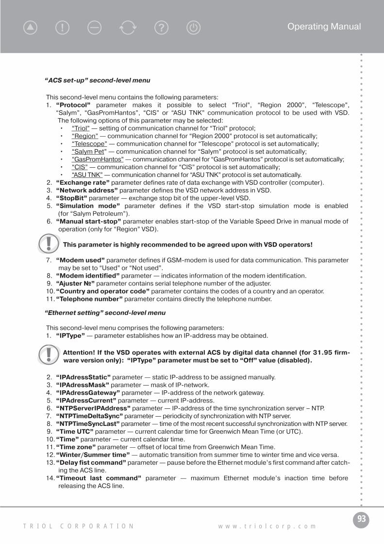
93T R I O L C O R P O R A T I O N w w w . t r i o l c o r p . c o m
Operating Manual
“ACS set-up” second-level menu
This second-level menu contains the following parameters:1. “Protocol” parameter makes it possible to select “Triol”, “Region 2000”, “Telescope”,
“Salym”, “GasPromHantos”, “CIS” or “ASU TNK” communication protocol to be used with VSD. The following options of this parameter may be selected:• “Triol” — setting of communication channel for “Triol” protocol;• “Region” — communication channel for “Region 2000” protocol is set automatically;• “Telescope” — communication channel for “Telescope” protocol is set automatically;• “Salym Pet” — communication channel for “Salym” protocol is set automatically;• “GasPromHantos” — communication channel for “GasPromHantos” protocol is set automatically;• “CIS” — communication channel for “CIS” protocol is set automatically;• “ASU TNK” — communication channel for “ASU TNK” protocol is set automatically.
2. “Exchange rate” parameter defines rate of data exchange with VSD controller (computer).3. “Network address” parameter defines the VSD network address in VSD.4. “StopBit” parameter — exchange stop bit of the upper-level VSD.5. “Simulation mode” parameter defines if the VSD start-stop simulation mode is enabled
(for “Salym Petroleum”).6. “Manual start-stop” parameter enables start-stop of the Variable Speed Drive in manual mode of
operation (only for “Region” VSD).
This parameter is highly recommended to be agreed upon with VSD operators!
7. “Modem used” parameter defines if GSM-modem is used for data communication. This parameter may be set to “Used” or “Not used”.
8. “Modem identified” parameter — indicates information of the modem identification.9. “Ajuster №” parameter contains serial telephone number of the adjuster.10. “Country and operator code” parameter contains the codes of a country and an operator.11. “Telephone number” parameter contains directly the telephone number.
“Ethernet setting” second-level menu
This second-level menu comprises the following parameters:1. “IPType” — parameter establishes how an IP-address may be obtained.
Attention! If the VSD operates with external ACS by digital data channel (for 31.95 firm-ware version only): “IPType” parameter must be set to “Off” value (disabled).
2. “IPAdressStatic” parameter — static IP-address to be assigned manually.3. “IPAdressMask” parameter — mask of IP-network.4. “IPAdressGateway” parameter — IP-address of the network gateway.5. “IPAdressCurrent” parameter — current IP-address.6. “NTPServerIPAddress” parameter — IP-address of the time synchronization server – NTP.7. “NTPTimeDeltaSync” parameter — periodicity of synchronization with NTP server.8. “NTPTimeSyncLast” parameter — time of the most recent successful synchronization with NTP server.9. “Time UTC” parameter — current calendar time for Greenwich Mean Time (or UTC).10. “Time” parameter — current calendar time.11. “Time zone” parameter — offset of local time from Greenwich Mean Time.12. “Winter/Summer time” — automatic transition from summer time to winter time and vice versa.13. “Delay fist command” parameter — pause before the Ethernet module’s first command after catch-
ing the ACS line.14. “Timeout last command” parameter — maximum Ethernet module’s inaction time before
releasing the ACS line.

94А Т . 6 5 4 2 2 6 . 2 4 2 - 3 2 O M
“Display set-up” second-level menu
This second-level menu comprises the following parameters:1. “Nos. display” parameter — makes it possible to display numbers of parameters with their names.2. “Text scrolling” parameter makes it possible to scroll text values in a circle at editing text
parameters.3. “Menu scrolling” parameter defines a possibility of the menu movement around a circle at editing.4. “Accelerated editing” parameter makes it possible to increase the rate of change of the numeric
parameter values.5. “Contrast” parameter — setting of the controller display contrast. Display contrast enhances as this
value increases.6. “LCD temp. comp.” parameter makes it possible to set display contrast automatically depending
on ambient temperature. It may be set to “On”/”Off”.7. “Case temp.2” parameter — value of air temperature in the UMKA-03 case.
“Setting universal time” second-level menu
1. “Time” parameter — setting of current date and astronomical time.2. “681 Winter/Summer time” switching-on an automatic transition from summer time to winter time
and vice versa. This parameter may be set to:
• “Off” — disables automatic revert to standard time from summer time to winter time and vice versa;• “On” — enables automatic revert to standard time from summer time to winter time and vice versa.
3. “Time” parameter — reference parameter representing particular time (“Winter” or “Summer”).4. “Factory settings” parameter makes it possible to reset current time settings to the default
(factory) ones.
“Statistics” second-level menu
This second-level menu comprises the following parameters:1. “ESM oper. time” parameter — indication of ESM operating time.2. “ESM downtime” parameter — indication of VSD down time after a regular start.3. “Number of starts” parameter — indicates number of VSD starts.4. “Overload stop num” parameter — indicates number of stops caused by ESM overload.5. “Underload stop num” parameter — indicates number of stops caused by ESM underload.6. “Other prot. stop num” parameter — indicates number of stops caused by operation of other protections.7. “Counters” parameter is used for zeroing values of counters.8. “Total operating time” parameter — indicates total operating time of the Variable Speed Drive.
“Energy meter” (This option is unavailable in actual specification of VSD)
This second-level menu comprises the following parameters:1. “Energy meter” parameter — defines if the electricity supply meter used for. This parameter may be
set to “Used”, “Not Used”. If the parameter is set to “Not Used” the following parameters are displayed:2. “Act/ energy from reset” parameter is a value of forward-direction active energy.3. “React. energy from reset” parameter is a value of forward-direction reactive energy.4. “PrecedDay Act Energy” parameter is a value of forward-direction active energy over the preceding day.5. “PrecedDay React Energy” parameter is a value of forward-direction reactive energy over
the preceding day.6. “Act. energy for the day” parameter is a value of forward-direction active energy over the current day.7. React. energy for the day” parameter is a value of forward-direction reactive energy over
the current day.8. “653 Energy meter” parameter is used for resetting the energy meter.

95T R I O L C O R P O R A T I O N w w w . t r i o l c o r p . c o m
Operating Manual
“Current timers” second-level menu
This second-level menu comprises the following parameters:1. “Last start cause” parameter represents a source of the START command.It may be set to “No error, Drive Connect, WrDrv, VersPO, DMEConn, EmergStop, Rinsulation, Door,
ContGage, PsucMax (Min), P ESM Max (Min), T°ambMax (Min), T° ESM Max (Min), VibrXyMax (Min), VibrZMax (Min), PannMax (Min), PbufMax (Min), PLinMax (Min), h annMax (Min), DA1…DA2Max (Min), HighVolt (LowVolt), Uunbal, Underload, Overload, MinFreq, CurrUnb, COTF, Turbine, PowSw U (V, W), Т°Sw. U (V, W), Т°discr, Ud max, Ud min, Overcurrent, NoAccel, BadSupp, PhFail, Phasing CBA, NotReady, Operator, ACS, Timer, SupplOn”.
2. “Last stop cause” parameter indicates a source of the STOP command. It has the same options as the “Last start cause” parameter.
3. “Start time” parameter indicates time when the last START command has been issued.4. “Stop time” parameter indicates time when the last STOP command has been issued.5. “The reason of the next start/stop” parameter indicates a reason of the latest start.6. “635 Time to ARC” parameter indicates time to ARC.7. “Power-up time” parameter — time of the last power-up.8. “Power-off time” parameter — time of the last power-off.9. “Time from start” parameter — countdown from the last start.10. “Time from stop” parameter — countdown from the last stop or from power-up.11. “ARC locked” parameter shows it the ARC locking is enabled.12. “Planned ARC” parameter defines if ARC will take place.13. “Too many ARC” parameter defines a reason due to which another ARC will not take place.14. “Start cause” parameters — reference parameters characterizing the Variable Speed Drive current state.15. “Stop cause” parameters — reference parameters characterizing the VSD current state.
“VSD parameters” second-level menu
All the parameters of the second-level menu “VSDC parameters” shall be set by specialists of Triol Corporation! Unauthorized change of these parameters may cause the equipment malfunction!
1. “VSD type” parameter — coding of the VSD type.2. “VSD serial No.” parameter — VSD serial number.3. “VSD manufacture date” parameter — date of the VSD manufacture — day, month, year.
“VSDC parameters” second-level menu
All the parameters of the second-level menu “VSDC parameters” shall be set by spe-cialists of Triol Corporation! Unauthorized change of these parameters may cause the equipment malfunction!
1. “VSDC serial No.” parameter — serial number of the Variable Speed Drive controller.2. “VSDC manufacture date” parameter — date of manufacture of the VSD controller — day, month,
year, time of installation.3. “VSDC software install date” parameter — date of installation of the VSD controller software —
day, month, year.4. “VSDC software version” parameter — indicates the VSD controller software version.5. “Subversion Number” parameter — indicates the VSD controller software subversion.6. “Drive software version” parameter — version No. of software for the VSD controller which controls
the frequency converter.7. “Drive type” parameter — type of a drive.8. “Language (язык)” is intend to chose the actual language of the controller (Russian/English).

96А Т . 6 5 4 2 2 6 . 2 4 2 - 3 2 O M
Working with USB flash drivesAll operations with USB flash drive shall be conducted as follows:1. Connect USB flash drive to the jack on the controller front panel.
If USB flash drive is connected to a running controller the event log will be written to this drive automatically.
2. Enter the “System / Operation with USB/” menu.3. Depending on the action to be done one of the parameters described in Table 2.7, shall be edited
by setting it to “Yes”.
Table 2.7 — List of parameters
Parameter nameOperation
execution time, sBrief description operations
«Read log» 2 – 15 Rewrites event log controller to USB flash drive
«Upgrade settings» 3 Rewrites settings from USB flash controller***
«Save settings to flash» 3 Extracts all settings from controller to USB flash drive
«Change firmware» 30 – 45Changes the controller firmware to that saved in USB flash drive****
«Download help» 3 Rewrites help file from USB flash drive to controller
«Download screen-saver» 3Rewrites screen-saver file from USB flash drive to controller
«Upgrade loader» 3Upgrades the utility responsible for the software downloading from USB flash drive to controller
The message will disappear in 30 – 45 sec, and the controller will start running new program.4. If to carry out the action selected the controller shall define more exactly what particular file is
required for operator a file selection menu will be displayed. Select an appropriate file using “Down” or “Up” keys and press “Enter” key. If more precise definition is not required (a single file of interest on USB flash Drive) the file selection menu is not displayed.
5. Time to the action termination is shown on the controller display.
*** — setup file is created using service software, and it may contain either all the controller’s set values or some of them. When updating set values through the USB flash drive only those available in the file may be changed.
**** — firmware replacement procedure differs from the similar ones in that a special message will be generated within 2–3 seconds warning that the VSD power supply may be interrupted in the process of the controller reflashing.
Before replacing the controller’s firmware by one with a new version it’s necessary to read the log, and after replacing the firmware the controller’s log shall be cleared to ensure proper functioning of the service software. If the controller’s firmware has been replaced by one with a new subversion, there is no need for clearing the log after reflashing.

97T R I O L C O R P O R A T I O N w w w . t r i o l c o r p . c o m
Operating Manual
6. Upon completion of the action a pop-up help appears. It characterizes the action result. Edited parameter is set to “No” again. Now working with the controller in a normal mode may be continued.
It is strictly prohibited to remove USB flash drive from the jack until the action is over! This may cause a failure not only of the USB flash drive but of the VSD controller as well.
Parameters, given in Table 2.8, characterize availability of some files in the controller memory.
Table 2.8 — Availability of files memory controller
Parameter name Options Parameter description
«USB flash»«Not identified», «Transcend»,
«Kingston»…..Indicates type of the USB flash drive connected
«Help file» «Not available», «Available»Indicates available of the help in the controller memory
«Screen-saver file» «Not available», «Available»Indicates available of the screen-saver in the controller memory
File allocationInformation on the file types supported by the controller is given in table 2.9. All files the UMKA-03
controller is dealing with are located in the “:/UMKA-3” folder in the disk root. File name is made up of fixed beginning (“UM_”), file No. in a directory and the file extension. Thus, up to 1000 files of the same type may be stored on a single USB flash drive.
Table 2.9 — File types supported controllers
Parameter name File name Text title File size
Event log UM3_0001.JRN «field_0001_well_0001_30-06-2015_09-55-02.jrn»130 KB —
4,3 MB
Controller’s firmware UM3_0001.LDR «Exe_File_for_Umka_3_Version_0001.LDR»200 KB — 2 MB
Set value file created by service software
UM3_0001.STT «Settings_File_for_Umka_3_Version_0001.STT» <5 KB
Set value file written from controller memory
UM3_0001.STT « field_0001_well_0001_30-06-2015_09-55-02.stt» <5 KB
Help file UM3_0001.HLU «Help_File_for_Umka_3_Version_0001.HLU» <500 KB
Screen-saver file UM3_0001.SCR «ScreenPict_File_for_Umka_3_Version_0001.SCR» 10 KB
Loader file UM3_0001.BOT «Bootloader_File_for_Umka_3_Version_0001.BOT» <30 KB
Each file has a header with additional information about its content. To make the header text visible it’s neces-sary to open this file using any text editor. First line — file header.
When saving files from USB flash drive to PC the service software renames the files giving them names taken from the file header.

98А Т . 6 5 4 2 2 6 . 2 4 2 - 3 2 O M
2.3.3.14. “Event log” first-level menu
If “Log viewing mode” option is selected the controller does into the event log viewing mode.
“Stops-starts log viewing mode” second-level menu
This second-level menu includes parameters displaying power-up/power-off time and date as well as ESM start’s and stop’s time and date.
“Editing log viewing mode” second-level menu
This second-level menu includes parameters displaying date and time of the parameter editing as well as the parameter to be edited.
“Viewing mode set-up” second-level menu
This second-level menu comprises the following parameters:1. “Viewing Starts/Stops” parameter defines if records of the ESM starts and stops will be displayed
in the log viewing mode.2. “Viewing emergency trip” parameter defines if records of the ESM trips caused by Variable Speed
Drive protections will be displayed in the log viewing mode.If a trip takes place the trip record will contain parameter values characterizing and describing just this particular trip.
3. “Viewing param. changes” parameter defines if records of changes (programming) of the Variable Speed Drive parameters will be displayed in the log viewing mode.
4. “Viewing currents” parameter defines if values of the VSD output current contained in the records will be displayed in the log viewing mode.
5. “Viewing voltages” parameter defines if values of the VSD output voltage contained in the records will be displayed in the log viewing mode.
6. “Viewing currents and voltages” parameter defines if values of the VSD output current and output voltage contained in the records will be displayed in the log viewing mode.
7. “Viewing DME data” parameter defines if records of the parameter values specified in the “Downhole measure equipment” (TMS) item of this menu will be displayed in the log viewing mode.
8. “Viewing well-head and transducers” parameter defines if values of the well-head transducers contained in the records will be displayed in the log viewing mode.
9. “Viewing events” parameter defines if event records will be displayed in the log viewing mode.10...16. “Viewing arbitrary Param. 1”...”Viewing arbitrary Param. 4” parameters define if values
contained in the records will be displayed in the log viewing mode.17. “Electric energy display” parameter — displaying trend lines and network characteristics when
reviewing the event log.18. “Search by time” parameter — for setting parameters ensuring selection of the date when events
to be viewed happened. Search of events by time enables fast and convenient finding of a required record in the event log. It needs to specify a required month and day. When entering “Log viewing mode” item of this menu the event happened at the same time or earlier defined by “Search by time” parameter will be displayed.
This parameter may be set to:• “Disable” — disabling search by date. The latest event will be highlighted in the log viewing
mode.• “Permit” — enabling search by date. The event happened at the same time or earlier defined by
“Search by time” parameter will be highlighted in the log viewing mode.19. “Search” parameter defines a date when the event displaying has begun.20. “Log” parameter makes it possible to delete all records in the event log.

99T R I O L C O R P O R A T I O N w w w . t r i o l c o r p . c o m
Operating Manual
Access to clearing procedure is password protected!
List of parameters in trends of currents, voltages, telemetry and well-head transducers is given in Table 2.10.
Table 2.10 — List of parameters in the trends of currents, voltages, telemetry and estuarine (annulus) sensors
Trend List of parameters displayed
Trend of currents
“Total ESM current”, “ESM active current”, “Output frequency”, “Load factor”, “Efficiency factor”, “ESM current, U phase”, “ESM current, V phase”, “ESM current, W phase”, “ESM voltage”
“Output Voltage”, “ESM active current”, “Current unbalance”, “Current R ins”, one of “U (V, W) phase IGBT temp.” parameters having maximum value of the “Overcurrent protection”
Trend of voltages
“AB in. voltage”, “BC in. voltage”, “CA in. voltage”, “Output Voltage”
“In. voltage unbal.”, “Ud voltage”, “Current R ins”, “Freq. backspin” (turbine rotation frequency)
Trend of currents and
voltages
“Total ESM current”, “ESM active current”, “Output frequency”, “Load factor”, “Efficiency factor”, “ESM current, U phase”, “ESM current, V phase”, “ESM current, W phase”, “ESM voltage”, “AB in. voltage”, “BC in. voltage”, “CA in. voltage”, “In. voltage unbal.”
“Output Voltage”, “ESM active current”, “Current unbalance”, “Current R ins”, one of “U (V, W) phase IGBT temp.” pa-rameters having maximum value of the “Overcurrent protection”, “Ud voltage”,
“Current Rins”, “Freq. backspin” (turbine rotation frequency)
Telemetry (DME) trend
“Intake pressure”, “Compensator pressure”, “Ambient temperature”
“ESM oil temperature”, “XY vibration”, “Z vibration”
Well-head trend
“Annulus pressure”, “Buffer pressure”, “(Flow) Line pressure”
“Annulus level”, “Add. Ain1.”, “Add. Ain2.”
“Set. regist. by time” second-level menu
1. “Rec. time oper” parameter defines recording time for parameters of voltage, current and teleme-tering system in operation.
2. “Urgent rec.” parameter defines recording time for all the parameters when set value of any of them is exceeded.
3. “Rec. time stop” parameter defines recording time for input voltage parameters when the motor is shut down.
4. “DME rec. period” parameter defines recording time for parameters of the telemetering system in operation and for those of external transducers.
5. “Rec. time start” parameter defines recording time for all the parameters after the motor has start running. Parameters are registered at one-second intervals.
6. “Supply failure rec time” parameter is a period of recording actual voltage values into the log in event of the network fault that impedes starting (LowVolt, HighVolt, Uunbal, PhFail).
7. “TM Triol measurement registr. time” — parameter is a period of recording readings of Triol telemetry into the log.
8. “Electric energy registr.(once/day)” parameter is a period of recording (watt-hour) meter readings into the log (once per day).

100А Т . 6 5 4 2 2 6 . 2 4 2 - 3 2 O M
“Set. regist. by changes” second-level menu
1. “ΔI ESM registered” parameter defines a minimum change of the VSD output current which implies registration in the event log. The following parameters are registered in the event log:
“505 Total ESM current”, “698 VSD total current”, “699 VSD active current”, “003 Output frequency”, “017 Load factor”, “016 Efficiency factor”, “004 ESM current, phase U”, “005 ESM current, phase W”, “006 ESM current, phase V”, “007 Current unbalance”.
2. “ΔU registered” parameter defines a minimum change of line voltage which implies registration in the event log. The following parameters are registered in the event log: “018 RS input voltage” (AB),
“019 ST input voltage” (BC), “020 TR input voltage” (CA), “In. voltage unbal.”, “Ud voltage”.3. “ΔIntake pressure registered” parameter defines a minimum change of intake pressure that implies
registration in the event log.4. “ΔCompens.press.recorded” parameter defines a minimum change of compensator pressure
that implies registration in the event log.5. “Δ Temp. amb. Registered” parameter defines a minimum change of ambient temperature in a well
that implies registration in the event log.6. “Δ Temp. ESM Registered” parameter defines a minimum change of ESM temperature that implies
registration in the event log.7. “Δ Vibr. Registered” parameter defines a minimum change of vibration that implies registration in
the event log.8. “Δ Pannulus registered” parameter defines a minimum change of annulus pressure that implies
registration in the event log.9. “ΔPbuff registered” parameter defines a minimum change of buffer pressure that implies registra-
tion in the event log.10. “Δ Pline registered” parameter defines a minimum change of flow line pressure that implies
registration in the event log.11. “Level annulus registered” parameter defines a minimum change of flow level in annulus that
implies registration in the event log.12. “Δ Add. Ain1. registered” parameter defines a minimum change of a parameter, measured through
analog input 1, that implies registration in the event log.13. “Flow rate register” parameter defines a minimum change of delivery rate that implies registration
in the event log.14. “Δ Add. Ain2. registered” parameter defines a minimum change of a parameter, measured through
analog input 2, that implies registration in the event log.
“Set. regist. custom” second-level menu
1. “Parameter №1” – “Parameter №7” parameters — for setting registration of a user chosen pa-rameter in the event log.
2. “Δ Parameter No.1 registered” – “Δ Parameter No.7 registered” parameters — for setting mini-mum change of a user parameter to be registered in the event log.
For example, if “Parameter №1” option is selected a parameter selection procedure is initiated for setting the parameter registration. If “Add parameter” option is selected a User goes to main menu of the UMKA-03 controller. The procedure is assumed completed when a required parameter to be displayed is selected in the menu by User.
If “End list” option is selected after parameter selection the “Absent” option is restored.“Parameter No. ...” and “Δ Parameter No. ... registered” parameters are interconnected. For example,
if output frequency is selected as Parameter No.1, “ΔParameter No.1 registered “ will be displayed in Hz.

101T R I O L C O R P O R A T I O N w w w . t r i o l c o r p . c o m
Operating Manual
2.3.3.15. “Start-up graph” first-level menu
Start-up graphs depict parameter changes within 30 sec from the start.The second-level menu contains start-up graphs for the latest 16 starts. Screen of the UMKA-03 controller
with a list of start-up graphs is shown in Fig. 2.12.
Figure 2.12 — Screen view of UMKA-03 controller with a list of starting diagrams
Controller allows viewing start-up graphs for the following parameters:• Total ESM current;• ESM active current;• Output frequency;• ESM current, U phase;• ESM current, V phase;• ESM current, W phase.
Screen in the mode of viewing the start-up graph for the ESM active current is shown in Fig. 2.13.
Start-up graph name Date and time of the start
Start No
Cursor
Parameter valueat the cursor position
Time expired from the start (at the cursor position)
ss
Start-up graph of the Active ESM current
Figure 2.13 — Screen view of UMKA-03 controller in viewing mode of starting diagram of ESM active current
Cursor movement is controlled by “ ” and “ ” keys. Parameter value corresponding to the cursor posi-tion is displayed by the controller at the bottom of the screen.

102А Т . 6 5 4 2 2 6 . 2 4 2 - 3 2 O M
2.3.3.16. “Emergency graph” first-level menu
Emergency graphs depict parameter changes 4 sec before the Variable Speed Drive is tripped.The second-level menu contains emergency graphs for the latest 16 stops. Screen of the UMKA-03
controller with a list of emergency graphs is shown in Fig. 2.14.
Stop Ready Auto. 11:43:37
Emergency graphs 19 Mar 2010 15:52:14Emergency graphs 19 Mar 2010 15:50:41
Figure 2.14 — Screen view of UMKA-03 controller with a list of emergency diagrams
Controller allows viewing stop graphs for the following parameters:• Ud voltage;• ESM active current;• Total ESM current;• Output Voltage.
Screen in the mode of viewing the Ud voltage emergency graph is shown in Fig. 2.15.
Figure 2.15 — Screen controller UMKA-03 when viewing the emergency diagram of voltage Ud
Cursor movement is controlled by “ ” and “ ” keys.Parameter value corresponding to the cursor position is displayed by the controller at the bottom of the screen.Emergency event log cannot be written to the USB flash Drive in automatic mode. To this effect it’s necessary
to enter “System” — “Operation with USB” — “Save emergency log”.

103T R I O L C O R P O R A T I O N w w w . t r i o l c o r p . c o m
Operating Manual
3. Transportation
Variable Speed Drives shall be transported packed.VSD may be transported by any kind of roofed transport in accordance with applicable laws and regula-
tions.Transportation conditions for VSD shall correspond to consequence climate variations:• ambient temperature of –20 to +60 °C (the characteristic –40 to +60 °C under the order);• relative humidity 100 % at + 25 °C;• for content of corrosion-active agents in atmosphere according to UL1332 standard.Environment shall be non-explosive, free of corrosive gases or vapors in such concentration that may
cause destruction of metals and insulation, and not saturated with current-conducting dust.Cargo-handling operations with the help of cargo cranes and mechanisms shall be performed by spe-
cially trained personnel proved to have enough labour safety knowledge.Packed VSD shall be lifted by a forklift loader from below; unpacked Variable Speed Drive by slinging
fixtures located at the upper part. Diagram of slinging is given in Fig. 3.1.
max 90°
Figure 3.1 — Scheme of VSD slinging
Slinging of the cargo must be performed using slings corresponding to the weight of cargo to be hoisted with due regard to the number of legs and the sling angle. General duty slings shall be selected so that the angle between the legs does not exceeded 90°.
It shall be transported as a separate package.Arrangement and fixing of Variable Speed Drives in a vehicle must ensure their stable position excluding
displacements or impacts against each other and against the vehicle walls.Keep VSD upright, do not jerk or tilt them (tilt angle shall not exceed 5°) when transporting, loading-
unloading and handling.VSD must be hoisted and moved smoothly with no jerks or swinging.

104А Т . 6 5 4 2 2 6 . 2 4 2 - 3 2 O M
No persons shall be under VSD during hoisting, handling or lowering. Variable Speed Drive shall be low-ered only to the intended place where it can not be dropped, turned over or slided down.
VSD must be hoisted and handled only in original packing with due regard to the hoisting machine load-carrying capacity and values given in the table of allowable loads on loader forks depending on the center-of-gravity position.
Drive the forklift to the Variable Speed Drive at low Speed; put the forks under it so that the Variable Speed Drive is well centered to the forks and parallel to their axial line.
Hoisting and handling of VSD is prohibited using only one fork of the forklift loader.Hoisting and handling of VSD with only one fork is prohibited. When transporting Variable Speed Drives in
motor vehicles, they shall be arranged and fixed so that not to jeopardize pedestrians and other road users, to prevent their falling out of the truck body and to prevent the vehicle instability.
4. Storage
Storage conditions of the VSD should correspond to the operating conditions for the products with enclosure protection NEMA 4 as per requirements of NEMA 250-2008 standard (as it pertains to environment conditions).
Environment shall be non-explosive, free of containing corrosive gases or vapors in such concentration that may cause destruction of metals and insulation, and not saturated with current-conducting dust.
Maximum storage time before commissioning is 1 year.
Figure 5.2 A — Physical points of diode bridge connection to VSD AK06-XX-160, 250

105T R I O L C O R P O R A T I O N w w w . t r i o l c o r p . c o m
Operating Manual
5. Maintenance
5.1. Preparation of the VSD for operation
Preparing of Variable Speed Drives to operation is performed in the following order:1. Wipe electrical contacts with gasoline of B-70 type.2. Visually inspect the cabinet and make sure that there are no foreign objects inside.3. If dust or dirt are revealed, blow the power units, control units, structural and mounting elements with
dry compressed air under pressure of 4 – 6 kg/cm2.
Pay special attention to the heat-sinking surface.
4. Check and tighten, if required, all bolted and screwed connections of electrical circuits.
Pay special attention to the terminal blocks of external connections (power terminals and control circuit terminals).
5. Check the state and tightness of plug-and-socket detachable connections of control modules.6. Check the state of forced-cooling fans (rotational freedom, lack of inadmissible axial and radial plays,
slaps and runouts).7. Check the state and performance of door hinges and locks, grease rubbing parts if required.8. Reform DC-link capacitors.
Maintenance and repairs must be performed by trained qualified personnel in accordance with the requirements of the guidelines and regulations in force at the site of operation.
Variable Speed Drive does not demand constant presence of attendants while in operation. During work inside the VSD follow safety directions stated in Part 2.
Periodically, is not more rare than 1 time in 6 months, lead preventive inspection and audit of VSD:
1. Disconnect voltage of the feed source.2. Open box doors and doors of cable connection compartments on the back side of the box.3. Use a voltmeter to make sure that the DC link capacitors are free of voltage.4. Carry out visual inspection of the box and make sure that the box is free of foreign objects.5. If dust or dirt is found, blow the power units, control units, structural and mounting elements with
compressed air under pressure of 4 – 6 kg/cm2.
Pay special attention to the heat-sinking surface.
6. Check and tighten, if required, all bolted and screwed connections of electrical circuits.
Pay special attention to the terminal blocks of external connections (power terminals and control circuit terminals).
7. Control and if necessary tighten all accessible bolt and screwed connections of electric circuits.8. Check the state of forced-cooling fans (rotational freedom, lack of inadmissible axial and radial plays,
slaps and runouts).9. Check the state and performance of door hinges and locks, grease rubbing parts if required.
Default of the above-listed requirements can lead to failures and premature failing of the VSD. Local color change (discoloration or dimness) of load-bearing elements of the circuit design, connecting conductors, buses, crimped locks testifies to their exces-sive heating and aging.

106А Т . 6 5 4 2 2 6 . 2 4 2 - 3 2 O M
In order to reform power filter capacitors:• Connect output terminals of a laboratory autotransformer to a rectifying diode bridge (used diode
bridge should be suitable for voltage not less than 400 V and the current not less than 10 A);• Open the front door of the VSD. Connect the output of the diode bridge to the buses +Ud and – Ud with
due polarity. The points where the diode bridge shall be connected to the VSD are shown schemati-cally and physically in Fig. 5.1 and Fig. 5.2 (A, B, C) respectively.
Figure 5.1 — Connections of diode bridge (are shown on the part of VSD АК06-ХХ-630 electrical schematic diagram)
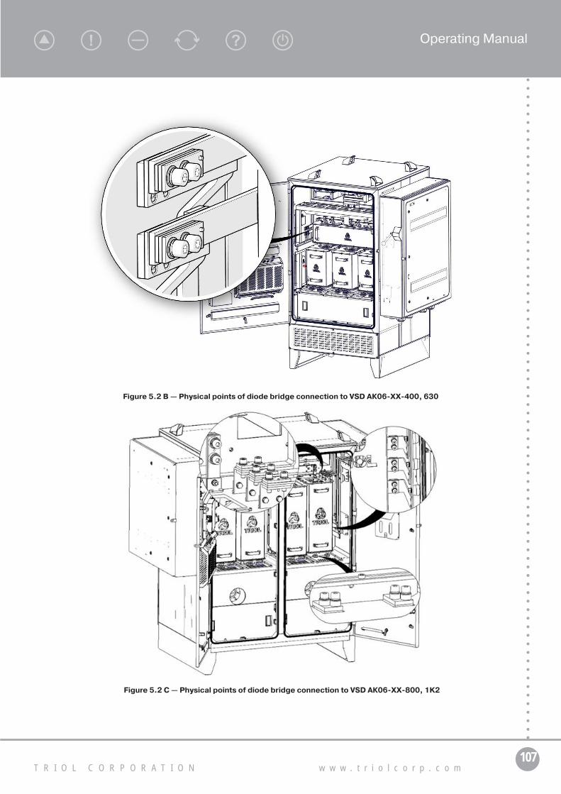
107T R I O L C O R P O R A T I O N w w w . t r i o l c o r p . c o m
Operating Manual
Figure 5.2 B — Physical points of diode bridge connection to VSD АК06-ХХ-400, 630
Figure 5.2 C — Physical points of diode bridge connection to VSD АК06-ХХ-800, 1K2

108А Т . 6 5 4 2 2 6 . 2 4 2 - 3 2 O M
5.2. Replacement of the VSD inverter power unit
WARNING: Do not connect and disconnect live connections. Electronic control units of vari-able speed drives contain components made on the basis of metal-oxide semiconductor (MOS) technology that is not tolerant to static electricity. If you need to touch some MOS component, ground your body and the tools to be used. When working with these units, place them on current-conducting pads.
Within 5 min after switching off the mains power, DC-link capacitors retain the dangerous charge. Before working inside the cabinet, make sure that the capacitors are free of voltage. Default of the above-listed requirements can lead to failures and premature failing of the VSD.
To power off the VSD, do as follows:• stop the motor if running;• if the motor is not running, make sure that there is no standby of the motor reclosure by AR or by
a timer. In the presence of standby (yellow indicator is “Waiting”, there is a corresponding message on the screen of the UMKA-03 controller), press the “STOP” button.
For powering off the VSD for a work that requires the door to be opened, switch off the automatic circuit breaker QF1 and QF2.
For replacement of the inverter power unit, disconnect control connector Х19, Х20; Х21, Х22; Х23, Х24; Х41; Х42; Х43 (DB-15 connector; see diagram АК06-ХХ-ХХХ-ХХХХХХ-ХХХ).
Then proceed to shut down of the power buses and disconnect the inverter power unit from the total frame (remove 10 screws per one inverter power unit). Withdraws the inverter unit by the handles on the shelf and specially designated fasteners places, see fig. 5.3 – 5.5.
Figure 5.3 — Off busbars on VSD АК06-ХХ-160, 250
Withdraws the inverter power unit by the handles on the shelf and specially designated fasteners places, see Fig. 5.6 – 5.8.

109T R I O L C O R P O R A T I O N w w w . t r i o l c o r p . c o m
Operating Manual
Figure 5.4 — Off busbars on VSD АК06-ХХ-400, 630
Figure 5.5 — Off busbars on VSD АК06-ХХ-800, 1K2

110А Т . 6 5 4 2 2 6 . 2 4 2 - 3 2 O M
Figure 5.6 — Off busbars on VSD AK06-XX-160, 250
Figure 5.7— Off busbars on VSD AK06-XX-400, 630

111T R I O L C O R P O R A T I O N w w w . t r i o l c o r p . c o m
Operating Manual
Figure 5.8 — Off busbars on VSD АК06-ХХ-800, 1K2
The new unit is to be installed in the reverse order.

112А Т . 6 5 4 2 2 6 . 2 4 2 - 3 2 O M
5.2.1. Replacement APF module inverter power unit
WARNING: Do not connect and disconnect live connections. Electronic control units of variable speed drives contain components made on the basis of metal-oxidesemicon-ductor (MOS) technology that is not tolerant to static electricity. If you need to touch some MOS component, ground your body and the tools to be used. When working with these units, place them on current-conducting pads.
Within 5 min after switching off the mains power, DC-link capacitors retain the dange-rous charge. Before working inside the cabinet, make sure that the capacitors are free of voltage. Default of the above-listed requirements can lead to failures and premature failing of the VSD.
To power off the VSD, do as follows:• stop the motor if running;• if the motor is not running, make sure that there is no standby of the motor reclosure by AR or by
a timer. In the presence of standby (yellow indicator is “Waiting”, there is a corresponding message on the screen of the UMKA-03 controller), press the STOP button.
For powering off the VSD for a work that requires the door to be opened, switch off the automatic circuit breaker QF1 and QF2.
For replacement of the inverter power unit, disconnect control connector XS 5.1, XS 5.2, XS 5.3 connectors (see diagram АК06-ХХ-ХХХ-ХХХХХХ-ХХХ).
Then proceed to shut down of the power buses and disconnect the inverter power unit from the total frame (remove 10 screws per one inverter unit), see Fig. 5.9.
Figure 5.9 — Dismantle APF module inverter power unit
Installation of the new unit is caring out in reverse order.

113T R I O L C O R P O R A T I O N w w w . t r i o l c o r p . c o m
Operating Manual
5.3. Replacement VSD rectifier power unit
WARNING: Do not connect and disconnect live connections. Electronic control units of variable speed drives contain components made on the basis of metal-oxidesemicon-ductor (MOS) technology that is not tolerant to static electricity. If you need to touch some MOS component, ground your body and the tools to be used. When working with these units, place them on current-conducting pads.
Within 5 min after switching off the mains power, DC-link capacitors retain the dange-rous charge. Before working inside the cabinet, make sure that the capacitors are free of voltage. Default of the above-listed requirements can lead to failures and premature failing of the VSD.
To power off the VSD, do as follows:• stop the motor if running;• if the motor is not running, make sure that there is no standby of the motor reclosure by AR or by
a timer. In the presence of standby (yellow indicator is “Waiting”, there is a corresponding message on the screen of the UMKA-03 controller), press the “STOP” button.
For powering off the VSD for a work that requires the door to be opened, switch off the automatic circuit breaker QF1 and QF2.
For replacement of the rectifier power unit, disconnect of Х17; Х18; Х46; X70; X71 (see diagram АК06-ХХ-ХХХ-ХХХХХХ-ХХХ).
Then proceed to shut down of the power buses and disconnect the inverter power unit from the total frame (remove 16 screws), see Fig. 5.10 – 5.12.
Figure 5.10 — Dismantle rectifier power unit on VSD АК06-ХХ-160, 250

114А Т . 6 5 4 2 2 6 . 2 4 2 - 3 2 O M
Figure 5.11 — Dismantling the rectifier unit on VSD АК06-ХХ-400, 630
Figure 5.12 — Dismantling the rectifier unit on on VSD АК06-ХХ-800, 1K2

115T R I O L C O R P O R A T I O N w w w . t r i o l c o r p . c o m
Operating Manual
Withdraws the rectifier power unit by the handles on the shelf and specially designated fasteners places, see Fig. 5.13 – 5.15.
Figure 5.13 — Dismantling the rectifier unit on VSD АК06-ХХ-160, 250
Figure 5.14 — Dismantling the rectifier unit on VSD АК06-ХХ-400, 630

116А Т . 6 5 4 2 2 6 . 2 4 2 - 3 2 O M
Figure 5.15 — Dismantling the rectifier unit on VSD АК06-ХХ-400, 630
The new unit is installed in the reverse order.

117T R I O L C O R P O R A T I O N w w w . t r i o l c o r p . c o m
Operating Manual
5.4. Replacement of the electronics unit (universal)
WARNING: Do not connect and disconnect live connections. Electronic control units of variable speed drives contain components made on the basis of metal-oxidesemicon-ductor (MOS) technology that is not tolerant to static electricity. If you need to touch some MOS component, ground your body and the tools to be used. When working with these units, place them on current-conducting pads.
Within 5 min after switching off the mains power, DC-link capacitors retain the dange-rous charge. Before working inside the cabinet, make sure that the capacitors are free of voltage. Default of the above-listed requirements can lead to failures and premature failing of the VSD.
Powering off the VSD it is necessary to:• stop the motor in the case if it worked;• if the motor is not running, make sure that there is no standby of the motor reclosure by AR or by
a timer. In the presence of standby (yellow indicator is “Waiting”, there is a corresponding message on the screen of the UMKA-03 controller), press the “STOP” button
For powering off the VSD for a work that requires the door to be opened, switch off the automatic circuit breaker QF1 and QF2.
For replacement of the rectifier power unit, disconnect control connectors of X44.1, X44.2, X44.3, X45, X47, X48.1, X48.2, X48.3, X49, X50, XT1 (see diagram АК06-ХХ-ХХХ-ХХХХХХ-ХХХ).
Then proceed to the dismantling of the electronics unit from the door (remove 4 screws with washers). See Fig. 5.16.
Figure 5.16 — Dismantling of the electronics unit
The new unit is to be installed in the reverse order.* Number of connectors may vary depending on the version of the product.

118А Т . 6 5 4 2 2 6 . 2 4 2 - 3 2 O M
5.5. Replacement VSD brake resistor unit
WARNING: Do not connect and disconnect live connections. Electronic control units of variable speed drives contain components made on the basis of metal-oxidesemicon-ductor (MOS) technology that is not tolerant to static electricity. If you need to touch some MOS component, ground your body and the tools to be used. When working with these units, place them on current-conducting pads.
Within 5 min after switching off the mains power, DC-link capacitors retain the dange-rous charge. Before working inside the cabinet, make sure that the capacitors are free of voltage. Default of the above-listed requirements can lead to failures and premature failing of the VSD.
Powering off the VSD it is necessary to:• stop the motor in the case if it worked;• if the motor is not running, make sure that there is no standby of the motor reclosure by AR or by
a timer. In the presence of standby (yellow indicator is “Waiting”, there is a corresponding message on the screen of the UMKA-03 controller), press the “STOP” button.
For powering off the VSD for a work that requires the door to be opened, switch off the automatic circuit breaker QF1 and QF2.
For replacement of the rectifier power unit, disconnect control connectors of X8.4; Х72, connect XT11, XT12, XT13; (see diagram АК06-ХХ-ХХХ-ХХХХХХ-ХХХ).
Then proceed to the dismantling of the brake resistor unit from the cabinet (remove 4 screws with washers), see Fig. 5.17.
Figure 5.17 — Dismantling of the brake resistor unit.
The new unit is to be installed in the reverse order.

119T R I O L C O R P O R A T I O N w w w . t r i o l c o r p . c o m
Operating Manual
5.6. Replacement of the transformer unit (universal)
WARNING: Do not connect and disconnect live connections. Electronic control units of variable speed drives contain components made on the basis of metal-oxidesemicon-ductor (MOS) technology that is not tolerant to static electricity. If you need to touch some MOS component, ground your body and the tools to be used. When working with these units, place them on current-conducting pads.
Within 5 min after switching off the mains power, DC-link capacitors retain the dange-rous charge. Before working inside the cabinet, make sure that the capacitors are free of voltage. Default of the above-listed requirements can lead to failures and premature failing of the VSD.
Powering off the VSD it is necessary to:• stop the motor in the case if it worked;• if the motor is not running, make sure that there is no standby of the motor reclosure by AR or by
a timer. In the presence of standby (yellow indicator is “Waiting”, there is a corresponding message on the screen of the UMKA-03 controller), press the STOP button
For powering off the VSD for a work that requires the door to be opened, switch off the automatic circuit breaker QF1 and QF2.
For replacement of the transformer unit, disconnect control the power and control wiring from the termi-nal blocks X6 and relays K1, K2, K3 (see diagram АК06-ХХ-ХХХ-ХХХХХХ-ХХХ).
Then proceed to dismantle the transformer unit from the frame (remove 8 nuts with washers)*, see Fig 5.18.
Figure 5.18 — Dismantling of the transformer unit
The new unit is to be installed in the reverse order.* Number of connectors may vary depending on the version of the product.

120А Т . 6 5 4 2 2 6 . 2 4 2 - 3 2 O M
5.7. Replacement of the preliminary charge unit of the APF module
WARNING: Do not connect and disconnect live connections. Electronic control units of variable speed drives contain components made on the basis of metal-oxidesemicon-ductor (MOS) technology that is not tolerant to static electricity. If you need to touch some MOS component, ground your body and the tools to be used. When working with these units, place them on current-conducting pads.
Within 5 min after switching off the mains power, DC-link capacitors retain the dange-rous charge. Before working inside the cabinet, make sure that the capacitors are free of voltage. Default of the above-listed requirements can lead to failures and premature failing of the VSD.
Powering off the VSD it is necessary to:• stop the motor in the case if it worked;• if the motor is not running, make sure that there is no standby of the motor reclosure by AR or by
a timer. In the presence of standby (yellow indicator is “Waiting”, there is a corresponding message on the screen of the UMKA-03 controller), press the “STOP” button.
For powering off the VSD for a work that requires the door to be opened, switch off the automatic circuit breaker QF1 and QF2.
For replacement of the preliminary charge unit, disconnect control connectors of XS4; Х52 (see diagram АК06-ХХ-ХХХ-ХХХХХХ-ХХХ).
Then proceed to the dismantling of the preliminary charge unit from the APF module (remove 4 screws with washers), see fig. 5.19.
Figure 5.19 — Dismantling of the preliminary charge unit
The new unit is to be installed in the reverse order.

121T R I O L C O R P O R A T I O N w w w . t r i o l c o r p . c o m
Operating Manual
5.8. Replacing APF module fan
WARNING: Do not connect and disconnect live connections. Electronic control units of variable speed drives contain components made on the basis of metal-oxidesemicon-ductor (MOS) technology that is not tolerant to static electricity. If you need to touch some MOS component, ground your body and the tools to be used. When working with these units, place them on current-conducting pads.
Within 5 min after switching off the mains power, DC-link capacitors retain the dange-rous charge. Before working inside the cabinet, make sure that the capacitors are free of voltage. Default of the above-listed requirements can lead to failures and premature failing of the VSD.
Powering off the VSD it is necessary to:• stop the motor in the case if it worked;• if the motor is not running, make sure that there is no standby of the motor reclosure by AR or by
a timer. In the presence of standby (yellow indicator is “Waiting”, there is a corresponding message on the screen of the UMKA-03 controller), press the STOP button
For powering off the VSD for a work that requires the door to be opened, switch off the automatic circuit breaker QF1 and QF2.
To replace fan APF module fan disconnect power and control wiring from terminal block and relays (see diagram АК06-ХХ-ХХХ-ХХХХХХ-ХХХ).
Then proceed to dismantle fan compartment cover(remove 4 screws with washers), see fig. 5.20.
.
Figure 5.20 — Dismantling APF module fan
Disconnect fan from terminal XT shown in Fig. 5.21.

122А Т . 6 5 4 2 2 6 . 2 4 2 - 3 2 O M
Figure 5.21 — Disconnect fan from terminal XT
Then dismantle fasteners APF module fan (remove 4 screws and washers) and fan, see Fig. 5.22.
Figure 5.22 — Dismantling APF module fan
The new unit is to be installed in the reverse order.

123T R I O L C O R P O R A T I O N w w w . t r i o l c o r p . c o m
Operating Manual
5.9. Replacing APF module main power contactor
WARNING: Do not connect and disconnect live connections. Electronic control units of variable speed drives contain components made on the basis of metal-oxidesemicon-ductor (MOS) technology that is not tolerant to static electricity. If you need to touch some MOS component, ground your body and the tools to be used. When working with these units, place them on current-conducting pads.
Within 5 min after switching off the mains power, DC-link capacitors retain the dange-rous charge. Before working inside the cabinet, make sure that the capacitors are free of voltage. Default of the above-listed requirements can lead to failures and premature failing of the VSD.
Powering off the VSD it is necessary to:• stop the motor in the case if it worked;• if the motor is not running, make sure that there is no standby of the motor reclosure by AR or by
a timer. In the presence of standby (yellow indicator is “Waiting”, there is a corresponding message on the screen of the UMKA-03 controller), press the STOP button
For powering off the VSD for a work that requires the door to be opened, switch off the automatic circuit breaker QF1 and QF2.
To replace APF module main power contactor disconnect power and control wiring from terminal block and relays (see diagram АК06-ХХ-ХХХ-ХХХХХХ-ХХХ).
Getting to removal APF module automaton from cabinet (remove 2 screws and washers); further dis-mantle main power contactor (remove the 4 screws with washers)*, see Fig. 5.23.
Figure 5.23 — Dismantling APF module main power contactor
The new unit is to be installed in the reverse order.
* Number of connectors may vary depending on the version of the product.

124А Т . 6 5 4 2 2 6 . 2 4 2 - 3 2 O M
5.10. Replacing APF module electronics unit
WARNING: Do not connect and disconnect live connections. Electronic control units of variable speed drives contain components made on the basis of metal-oxidesemicon-ductor (MOS) technology that is not tolerant to static electricity. If you need to touch some MOS component, ground your body and the tools to be used. When working with these units, place them on current-conducting pads.
Within 5 min after switching off the mains power, DC-link capacitors retain the dange-rous charge. Before working inside the cabinet, make sure that the capacitors are free of voltage. Default of the above-listed requirements can lead to failures and premature failing of the VSD.
Powering off the VSD it is necessary to:• stop the motor in the case if it worked;• if the motor is not running, make sure that there is no standby of the motor reclosure by AR or by
a timer. In the presence of standby (yellow indicator is “Waiting”, there is a corresponding message on the screen of the UMKA-03 controller), press the STOP button.
For powering off the VSD for a work that requires the door to be opened, switch off the automatic circuit breaker QF1 and QF2.
For replacement of the rectifier power unit, disconnect control connectors of S4.1 (DB-15), ХS4.2 (DB-15), ХS4.3 (DB-15), ХS3 (РП-10-7), ХP4.1 (DB-9), ХP4.2 (DB-9), ХP4.3 (DB-9), ХP5 (DB-9), see diagram АК06-ХХ-ХХХ-ХХХХХХ-ХХХ.
Then proceed to the dismantling of the electronics unit from the door (remove 4 screws with washers). See Fig. 5.24.
Figure 5.24 — Dismantling APF module electronics unit
The new unit is to be installed in the reverse order.

125T R I O L C O R P O R A T I O N w w w . t r i o l c o r p . c o m
Operating Manual
5.11. Replacing APF module main power contactor control relay
WARNING: Do not connect and disconnect live connections. Electronic control units of variable speed drives contain components made on the basis of metal-oxidesemicon-ductor (MOS) technology that is not tolerant to static electricity. If you need to touch some MOS component, ground your body and the tools to be used. When working with these units, place them on current-conducting pads.
Within 5 min after switching off the mains power, DC-link capacitors retain the dange-rous charge. Before working inside the cabinet, make sure that the capacitors are free of voltage. Default of the above-listed requirements can lead to failures and premature failing of the VSD.
Powering off the VSD it is necessary to:• stop the motor in the case if it worked;• if the motor is not running, make sure that there is no standby of the motor reclosure by AR or by
a timer. In the presence of standby (yellow indicator is “Waiting”, there is a corresponding message on the screen of the UMKA-03 controller), press the STOP button.
For powering off the VSD for a work that requires the door to be opened, switch off the automatic circuit breaker QF1 and QF2.
For replacement of APF module main power contactor control relay, disconnect power and control wiring from terminal block and relays (see diagram АК06-ХХ-ХХХ-ХХХХХХ-ХХХ).
Then proceed to the dismantling of APF module main power contactor control relay (remove 2 screws with washers). See Fig. 5.25.
Figure 5.25 — Dismantling APF module APF module main power contactor control relay
The new unit is to be installed in the reverse order.* Number of connectors may vary depending on the version of the product.
6. Disposal
Parts of the VSD do not contain substances or materials harmful or dangerous to human health and the environment. They can be disposed of without special precautions.

126А Т . 6 5 4 2 2 6 . 2 4 2 - 3 2 O M
Figure А1 — Overall dimensions of АК06-ММ/РМ/AM-160, 250 variable speed drives
Figure А2 — Overall dimensions of АК06-ММ/РМ/AM-160, 250 variable speed drives with open doors
Appendix А(reference)
Variable speed drive overall dimensions
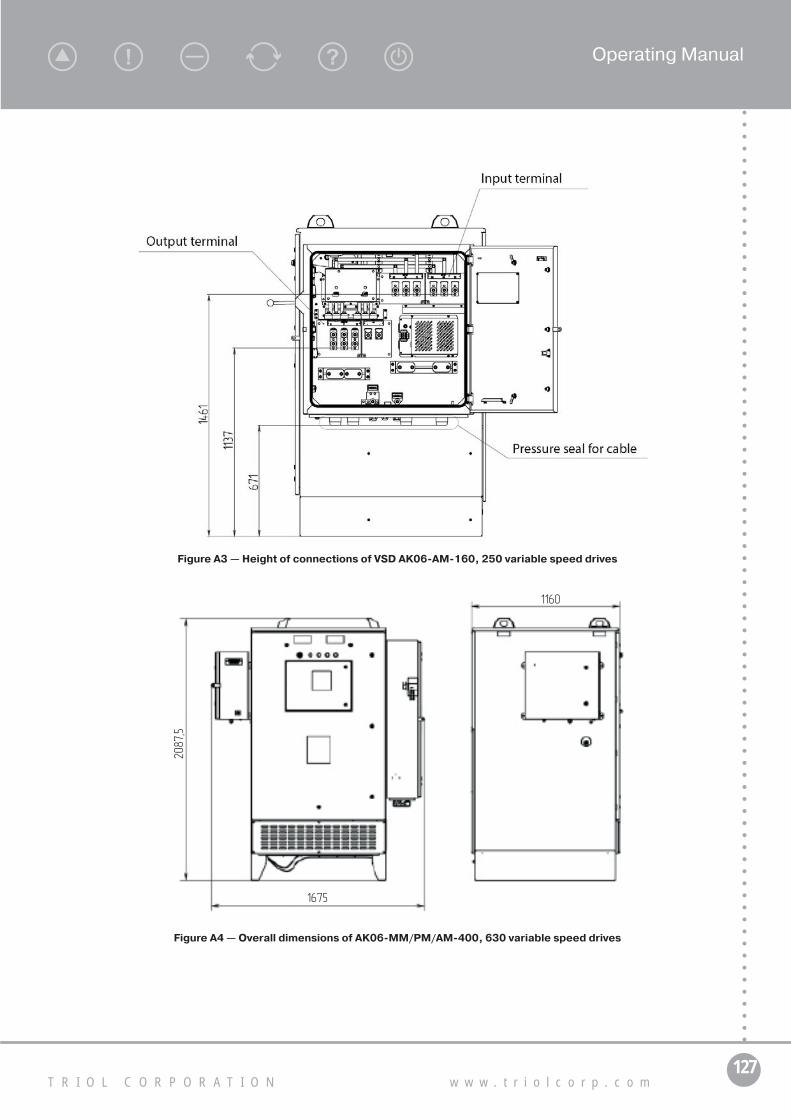
127T R I O L C O R P O R A T I O N w w w . t r i o l c o r p . c o m
Operating Manual
Figure A3 — Height of connections of VSD AK06-AM-160, 250 variable speed drives
2087
,5
1160
1675
Figure A4 — Overall dimensions of AK06-MM/PM/AM-400, 630 variable speed drives

128А Т . 6 5 4 2 2 6 . 2 4 2 - 3 2 O M
R575
R1021
R1014
120°
120°
120°
1617
1304
1037
Output terminal block
Input terminal block
«0 – ACVOT» terminal
Pressure seal for cable lead-in
(terminal for step-up transformer connection)
Figure A5 — Overall dimensions of AK06-MM/PM/AM-400, 630 variable speed drives with open doors
Figure A6 — Height of connections of VSD AK06-AM-400, 630

129T R I O L C O R P O R A T I O N w w w . t r i o l c o r p . c o m
Operating Manual
Figure А7 — Overall dimensions of АК06-ММ/РМ/AM-800, 1K2 variable speed drives
Figure А8 — Overall dimensions of АК06-ММ/РМ/AM-800, 1K2 variable speed drives with open doors

130А Т . 6 5 4 2 2 6 . 2 4 2 - 3 2 O M
Figure А9 — Height of connections of VSD АК06-АМ-800, 1K2

131T R I O L C O R P O R A T I O N w w w . t r i o l c o r p . c o m
Operating Manual
Variable speed driveAK06-AМ-630-110231-480 Normally closed contacts
ESP on
ESP common
ESP off
+24 V +24 V
Control of ESM operation
Power supply of discrete inputsCont.pr. gauge Contact pressure gauge Digital input, contact pressure gauge
Ain 1.1 Analog input 1
Ain common Common analog inputAin 2 Analog input 2
Connection sensors of submersible telemetry unit
ACS RS485 A+
ACS RS485 B-
Signal cable A RS485
Signal cable B RS485Connecting the external ACSby RS-485
ACS RS GND Neutral wire RS-485
Circuit Description Purpose
Signal cable A RS485
Signal cable B RS485
Neutral wire RS-485
Connect a digital telemetryRS-485
Connect a digital telemetryRS-232
Neutral wire RS232
Data transmission — RS232
Data receiving — RS232
Telemetry power supply 220 VAC
220 VAC
Internal/external circuit “ACVOT-0”
If the is a jumper in this terminal, Rizis measured by variable speeddrive, not by telemetry system
“ACVOT-0”
“ACVOT-0”
Chassis ACVOT ESM
Control circuit 220 VAC
GroundingGND
Inpu
t 3х4
80 V
of th
e st
ep-d
own
pow
er tr
ansf
orm
er
Circuit Description Purpose
Circuit Description Purpose
A
B
C
Neutral
TS TXD
TS RXDTS GND
TS RS GND
TS RS485 A+
TS RS485 B-
External interlock External interlocking of turn-on External interlocking of ESM start
Ain 2.1 Analog input 1
Ain common Common analog inputAin 2.2 Analog input 2
Connection sensors of submersible telemetry unit
XT12
X25
X26
Din reserve Reserve digital input Reserved digital input
Appendix B(mandatory)
Diagram of external VSD connections

132А Т . 6 5 4 2 2 6 . 2 4 2 - 3 2 O M
Appendix C(normative)
Instruction on telemetry unit connection
Instruction for connection the «Triol GTM-01-03 (-06)» telemetry unit to the VSDTo install the GTM unit into VSD, the mounting set is included into delivery set of GTM unit. It includes
brackets, fasteners, wires and cable for connection via RS-232 channel.Before installing the GTM unit into variable speed drive, brackets AT.301561.391, AT.301561.391-01
should be installed on the GTM unit.Procedure of GTM unit installing into the VSD:1. Prepare the mounting set (supplied with the GTM unit) as shown in Figure C.1.2. Using M5 screws attach the brackets to the GTM unit as shown in Figures C.2, C.3 and C.4.3. Disconnect the VSD. Further all connections should be made with the power supply disconnected.
Install GTM unit into its seat in VSD and fasten it with screws M5.
Figure С.1 — Mounting set for GTM unit installation

133T R I O L C O R P O R A T I O N w w w . t r i o l c o r p . c o m
Operating Manual
Figure С.2 — Brackets installation
Figure С.3 — Installation of bracketsАТ.301561.391
Figure С.4 — Installation of bracketsАТ.301561.391-01
Procedure of GTM unit installing into the VSD:1. Ground jumper AT.685616.134 should be connected to the grounding bolt of the GTM unit and to
the ground bus of the VSD.2. Connect «0-ACVOT» cable of the GTM unit to terminal block XT12 of VSD.3. Connect star point of transformer. cable to terminal HT12.4. Using two jumpers AT.685616.133 connect power supply 220 V to terminal X25, contacts 11,12.5. Connect telemetry unit TMN by RS-485 connector to pins 1, 2, 3 terminal X25 with jumpers
AT.685616.133.6. Fix the cables with the ties CCV-150 included into the set of GTM unit.
Figure С.5 — Telemetry compartment Figure С.6 — Connect to terminal block X25

134А Т . 6 5 4 2 2 6 . 2 4 2 - 3 2 O M
Appendix D (normative)
Description of UMKA-03 controller menu
Groups and their parameters
Parameter type
ValueManufacturer
set valueRange
ESM actual parameters Menu 1 level
003 Output frequency Inform. 0.00 Hz 0.00 Hz 0.00 Hz – 655.35 Hz
004 ESM current, phase U Inform. 0.0 A 0.0 A 0.0 A – 3276.7 A
005 ESM current, phase V Inform. 0.0 A 0.0 A 0.0 A – 3276.7 A
006 ESM current, phase W Inform. 0.0 A 0.0 A 0.0 A – 3276.7 A
007 Current unbalance Inform. 0.00 % 0.00 % 0.00 % – 327.67 %
701 ESM active current Inform. 0.0 A 0.0 A 0.0 A – 3276.7 A
505 Total ESM current Inform. 0.0 A 0.0 A 0.0 A – 3276.7 A
016 Efficiency factor Inform. 0.000 0 0.000 – 1.000
017 Load factor Inform. 0.0 % 0.0 % 0.0 % – 999.9 %
022 Current R ins Inform.20000 kOhm
0 kOhm 0 kOhm – 32767 kOhm
023 Freq. backspin Inform. 0.0 Hz 0.0 Hz 0.0 Hz – 800.0 Hz
014 Active power Inform. 0 kW 0 kW 0 kW – 32767 kW
015 Total power Inform. 0 kVA 0 kVA 0 kVA – 32767 kVA
Output reactive power Inform. 0 kvar 0 kvar 0 kvar – 32767 kvar
700 ESM voltage Inform. 0 V 0 V 0 V – 9999 V
VSD actual parameters Menu 1 level
003 Output frequency Inform. 0.00 Hz 0.00 Hz 0.00 Hz – 655.35 Hz
012 Ud voltage Inform. 527 V 0 V 0 V – 32767 V
Iout VSD phase U Inform. 0 A 0 A 0 A – 32767 A
Iout VSD phase V Inform. 0 A 0 A 0 A – 32767 A
Iout VSD phase W Inform. 0 A 0 A 0 A – 32767 A
699 VSD active current Inform. 0 A 0 A 0 A – 32767 A
698 VSD total current Inform. 0 A 0 A 0 A – 32767 A
018 RS input voltage Inform. 0 V 0 V 0 V – 32767 V
019 ST input voltage Inform. 0 V 0 V 0 V – 32767 V
020 TR input voltage Inform. 0 V 0 V 0 V – 32767 V
021 In. voltage unbal. Inform. 0.0 % 0.0 % 0.0 % – 3276.7 %
522 U phase IGBT temp. Inform. 112.7 °С 0.0 °С 0.0 °С – 150.0 °С
523 V phase IGBT temp. Inform. 112.7 °С 0.0 °С 0.0 °С – 150.0 °С
524 W phase IGBT temp. Inform. 112.8 °С 0.0 °С 0.0 °С – 150.0 °С
697 Output Voltage Inform. 0 V 0 V 0 V – 500 V
Table D1 — Description of UMKA-03 controller menu

135T R I O L C O R P O R A T I O N w w w . t r i o l c o r p . c o m
Operating Manual
Groups and their parameters
Parameter type
ValueManufacturer
set valueRange
Id current Inform. 0.3 A 0.0 A 0.0 A – 3276.7 A
Current phase rotation Inform. CBA ABC [ABC, CBA]
Actual input parameters Menu 1 level
R-phase current (A) Inform. 0.0 A 0.0 A 0.0 A – 3276.7 A
S-phase current (B) Inform. 0.0 A 0.0 A 0.0 A – 3276.7 A
T-phase current (C) Inform. 0.0 A 0.0 A 0.0 A – 3276.7 A
Active in. current Inform. 0.0 A 0.0 A 0.0 A – 3276.7 A
Total in. current Inform. 0.0 A 0.0 A 0.0 A – 3276.7 A
Input efficiency factor Inform. 0.000 0 0.000 – 1.000
Active in. power Inform. 0.0 kW 0.0 kW 0.0 kW – 3276.7 kW
Total in. power Inform. 0.0 kVA 0.0 kVA 0.0 kVA – 3276.7 kVA
In. reactive power Inform. 0.0 kvar 0.0 kvar 0.0 kvar – 3276.7 kvar
Modes of operation Menu 1 level
Manual/automatic Menu 2 level
000 Operating mode Set value Manual Manual [Manual, Automatic]
157 Maintain pararmeter Set value Manual F Manual F
[Manual F, Program F, Curr Regulator,
Suction Pressure, Wellhead Pressure, Annulus pressure,
Line pressure, Annulus level, ESM Act Power,
ESM pressure, AmbienTemp,
ESM Temp, XY Vibr, Z vibr, Manual U]
140 Rotation direction Set value Direct Direct [Direct, Reverse]
003 Output frequency Set value 0.00 Hz 0.00 Hz 0.00 Hz – 655.35 Hz
159 Frequency setting Set value 50.02 Hz 50.00 Hz 0.00 Hz – 80.00 Hz
500 Power-on start Set value Disable Disable [Disable, Permit]
073 Autorun time Set value 30 s 30 s 1 s – 9999 s
733 Deceleration method Set value Running-out Running-out [Running-out, Dynamic]
Setting error Set value Not available Not available
[Not available, VSDESP current,
ESM Irated, PID feedback,
U/F set, Power part, Open-circuit current,
Current setting, Impact time]
The continuation of Table D1

136А Т . 6 5 4 2 2 6 . 2 4 2 - 3 2 O M
Groups and their parameters
Parameter type
ValueManufacturer
set valueRange
Program mode Menu 2 level
157 Maintain parameter Set value Manual F Manual F
[Manual F, Program F, Curr Regulator,
Suction Pressure, Wellhead Pressure, Annulus pressure,
Line pressure, Annulus level, ESM Act Power,
ESM pressure, AmbienTemp,
ESM Temp, XY Vibr, Z vibr, Manual U]
003 Output frequency Set value 0.00 Hz 0.00 Hz 0.00 Hz – 655.35 Hz
Prog. mode act. Setting Set value 0.00 Hz 0.00 Hz 0.00 Hz – 80.00 Hz
194 Start. freq. Set value 40.00 Hz 40.00 Hz 5.00 Hz – 80.00 Hz
195 End freq. Set value 50.00 Hz 50.00 Hz 5.00 Hz – 80.00 Hz
Change time Set value 00:01 00:01 00:01 – 546:07
193 Prog. freq. change Set valueOne
start-up One
start-up [One start-up, Every start-up]
197 Underload init. Seting Set value 50.0 % 50.0 % 0.0 % – 100.0 %
Current regulator Menu 2 level
157 Maintain parameter Set value Manual F Manual F
[Manual F, Program F, Curr Regulator,
Suction Pressure, Wellhead Pressure, Annulus pressure,
Line pressure, Annulus level, ESM Act Power,
ESM pressure, AmbienTemp,
ESM Temp, XY Vibr, Z vibr, Manual U]
505 Total ESM current Set value 0.0 A 0.0 A 0.0 A – 3276.7 A
504 Current setting 100.1 A 100.0 A 1.0 A – 2000.0 A
The continuation of Table D1

137T R I O L C O R P O R A T I O N w w w . t r i o l c o r p . c o m
Operating Manual
Groups and their parameters
Parameter type
ValueManufacturer
set valueRange
Non-technol. parameter regulator
Menu 2 level
157 Maintain parameter Set value Manual F Manual F
[Manual F, Program F, Curr Regulator, Suc-
tion Pressure, Wellhead Pressure, Annulus
pressure, Line pres-sure, Annulus level,
ESM Act Power, ESM pressure,
AmbienTemp, ESM Temp, XY Vibr, Z vibr,
Manual U]
Current value PID Set value 0 at 0 at 0 at – 9999 at
Setting 5002 0 0 – 65535
Setting error Set value Not available Not available
[Not available, VSDESP current, ESM Irated,
PID feedback, U/F set, Power part, Open-circuit current,
Current setting, Impact time]
715 Intake press. Setting Set value 0.00 at 0.00 at 0.00 at – 400.00 at
719 Wellhead press. Setting Set value 0.00 at 0.00 at 0.00 at – 400.00 at
720 Annulus press. Setting Set value 0.00 at 0.00 at 0.00 at – 400.00 at
721 Line press. Setting Set value 0.00 at 0.00 at 0.00 at – 400.00 at
722 Annulus level setting Set value 0 m 0 m 0 m – 3000 m
Active Power Setting Set value 0 kW 0 kW 0 kW – 4000 kW
Compensator Pressure Setting Set value 0.00 at 0.00 at 0.00 at – 400.00 at
Amb Temperature Setting Set value 0.0 °С 0.0 °С 0.0 °С – 400.0 °С
ESM Temperature Setting Set value 0.0 °С 0.0 °С 0.0 °С – 400.0 °С
XY Vibration Setting Set value 0.00 m/s2 0.00 m/s2 0.00 m/с2 – 40.00 m/s2
Z Vibration Setting Set value 0.00 m/s2 0.00 m/s2 0.00 m/с2 – 40.00 m/s2
PID parameters Menu 2 level
161 Control direction Set value Direct Direct [Direct, Reverse]
162 Proportional Gain Set value 0.300 0.3 0.000 – 9.999
163 Integral gain Set value 0.300 0,3 0,000 – 9,999
164 Derivative gain Set value 0,100 0,1 0,000 – 9.999
165 Control period Set value 10.0 s 10.0 s 0.1 s – 999.9 s
The continuation of Table D1

138А Т . 6 5 4 2 2 6 . 2 4 2 - 3 2 O M
Groups and their parameters
Parameter type
ValueManufacturer
set valueRange
Operation by timer Menu 2 level
190 Prog. Operation Set value Disable Disable [Disable, With stop,
With Freq. 2]
191 Prog. operation time Set value 30 min 30 min 1 min – 32767 min
192 Prog. stop time Set value 10 min 60 min 1 min – 32767 min
T before timer state change Set value 00:30:00 00:00:00
Timer state Set value Stop Stop [Stop, Operation]
Shaking Menu 2 level
200 Shaking Set value Disable Disable [Disable, Permit]
201 Shaking period Set value 30 min 30 min 1 min – 1000 min
202 Amount of shakings Set value 2 2 0 – 99
203 F1 frequency Set value 40.00 Hz 40.00 Hz 1.00 Hz – 80.00 Hz
204 F2 frequency Set value 45.00 Hz 45.00 Hz 1.00 Hz – 80.00 Hz
206 Acceleration rate Set value 10.0 Hz/s 10.0 Hz/s 0.1 Hz/s – 60.0 Hz/s
205 Deceleration rate Set value 10.0 Hz/s 10.0 Hz/s 0.1 Hz/s – 60,0 Hz/s
Time before shaking Set value 00:00:00 00:00:00 00:00:00 – 02:46:39
Current optimization Menu 2 level
723 Ioptim. Search Set value Off Off [Off, On]
724 Limit Urated + Set value 20 V 20 V 1 V – 50 V
725 Limit Urated - Set value 20 V 20 V 1 V – 50 V
697 U/F curr. Urated Set value 380 V 100 V 100 V – 1000 V
727 Search period Set value 10 min 10 min 0 min – 9999 min
728 Filtration coefficient Set value 3.0 % 3.0 % 0.1 % – 10.0 %
505 Total ESM current Set value 0.0 A 0.0 A 0.0 A – 3276.7 A
I* ESM filter Set value 0.0 % 0.0 % 0.0 % – 999.9 %
I* ESM filter prev Set value 0.0 % 0.0 % 0.0 % – 999.9 %
Optimization state Set value Off Waiting [Waiting, Decrease U,
Increase U, Off]
Diagnostic modes Menu 2 level
Test mode Set value Off Off
[Off, Step-up transformer, Turbine rotation unit,
Loading]
379 Step-up tr. power Set value 0 kVA 0 kVA 0 kVA – 9999 kVA
SC in windings Set value Not tested Not tested [Not tested, No, Yes]
Low-voltage side breakdown Set value Not tested Not tested [Not tested, No, Yes]
Faulty Backspin Unit Set value Not tested Not tested [Not tested, No, Yes]
The continuation of Table D1

139T R I O L C O R P O R A T I O N w w w . t r i o l c o r p . c o m
Operating Manual
Groups and their parameters
Parameter type
ValueManufacturer
set valueRange
VSD current reference (loading) Set value 100.0 A 100.0 A 50.0 A – 2000.0 A
Leakage current Set value 0.5 A 0.0 A 0.0 A – 3276.7 A
Leakage current set value Set value 0.5 A 0.5 A 0.5 A – 5.0 A
Modes of start Menu 1 level
141 Startup mode Set value Swinging Soft
[Soft, With synchronization, Jogging, Swinging , Unblocking, Hard]
514 Acceleration rate Set value 5.00 Hz/s 1.00 Hz/s 0.10 Hz/s – 60.00 Hz/s
515 Deceleration rate Set value 5.00 Hz/s 1.00 Hz/s 0.10 Hz/s – 60.00 Hz/s
145 Sync. frequency Set value 30.00 Hz 30.00 Hz 0.10 Hz – 80.00 Hz
146 Sync. time Set value 5 s 5 s 1 s – 15 s
142 Jog frequency Set value 20.00 Hz 5.00 Hz 1.00 Hz – 20.00 Hz
143 Jog voltage Set value 120 % 120 % 100 % – 300 %
695 Jog time Set value 20 s 2 s 1 s – 50 s
144 Jog count Set value 5 10 1 – 20
712 Slip frequency Set value 2 % 2 % 1 % – 6 %
Acceleration rate (hard start) Set value 3.0 Hz/s 3.0 Hz/s 0.1 Hz/s – 80.0 Hz/s
Voltage rise factor Set value 25.0 % 25.0 % 0.0 % – 60.0 %
Unblocking frequency Set value 15.0 Hz 15.0 Hz 3.0 Hz – 20.0 Hz
Voltage rise rate Set value 150 V/s 150 V/s 10 V/s – 500 V/s
Voltage rise time Set value 7.0 s 7.0 s 0.2 s – 10.0 s
Unlocking Set value Off Off [Off, On]
Locked Set value No No [No, Yes]
Drive settings Menu 1 level
U/F characteristic Menu 2 level
149 Starting frequency Set value 4.00 Hz 1.50 Hz 1.00 Hz – 50.00 Hz
Point 1 frequency Set value 8.00 Hz 10.00 Hz 3.50 Hz – 80.00 Hz
Point 1 Voltage Set value 60 V 76 V 1 V – 152 V
Point 2 frequency Set value 66.66 Hz 20.00 Hz 3.50 Hz – 80.00 Hz
Point 2 Voltage Set value 152 V 152 V 1 V – 380 V
Point 3 frequency Set value 133.33 Hz 30.00 Hz 3.50 Hz – 80.00 Hz
Point 3 Voltage Set value 228 V 228 V 1 V – 420 V
Point 4 frequency Set value 200.00 Hz 50.00 Hz 3.50 Hz – 80.00 Hz
Point 4 Voltage Set value 380 V 380 V 1 V – 500 V
516 Min. freq. limit Set value 30.00 Hz 30.00 Hz 1.00 Hz – 50.00 Hz
693 Max. freq. limit Set value 200.00 Hz 50.00 Hz 10.00 Hz – 80.00 Hz
Rectifier U/F Set value No No [No, Yes]
The continuation of Table D1

140А Т . 6 5 4 2 2 6 . 2 4 2 - 3 2 O M
Groups and their parameters
Parameter type
ValueManufacturer
set valueRange
Calibration of ESM currents Menu 2 level
004 ESM current, phase U Set value 0.0 A 0.0 A 0.0 A – 3200.0 A
130 Cur. comp. factor phase U Set value 100.0 % 100.0 % 50.0 % – 200.0 %
005 ESM current, phase V Set value 0.0 A 0.0 A 0.0 A – 3200.0 A
131 Cur. comp. factor phase V Set value 100.0 % 100.0 % 50.0 % – 200.0 %
006 ESM current, phase W Set value 0.0 A 0.0 A 0.0 A – 3200.0 A
132 Cur. comp. factor phase W Set value 100.0 % 100.0 % 50.0 % – 200.0 %
Full-load current Set value 0.0 A 0.0 A 0.0 A – 3200.0 A
FL cur. comp. factor Set value 100.0 % 100.0 % 97.5 % – 102.5 %
Calibration of input voltages Menu 2 level
018 АВ in. voltage Set value 0 V 0 V 0 V – 1000 V
671 ADC comp. Uab Set value 100.0 % 100.0 % 50.0 % – 200.0 %
019 ВC in. voltage Set value 0 V 0 V 0 V – 1000 V
674 ADC comp. Ubc Set value 100.0 % 100.0 % 50.0 % – 200.0 %
020 CA in. voltage Set value 0 V 0 V 0 V – 1000 V
677 CA in. voltage Set value 100.0 % 100.0 % 50.0 % – 200.0 %
Calibration of input currents Menu 2 level
R-phase current (А) Set value 0.0 A 0.0 A 0.0 A – 3200.0 A
Phase R current comp. factor (A) Set value 100.0 % 100.0 % 50.0 % – 200.0 %
S-phase current (B) Set value 0.0 A 0.0 A 0.0 A – 3200.0 A
Phase S current comp. factor (B) Set value 100.0 % 100.0 % 50.0 % – 200.0 %
T-phase current (C) Set value 0.0 A 0.0 A 0.0 A – 3200.0 A
Phase T current comp. factor (C) Set value 100.0 % 100.0 % 50.0 % – 200.0 %
Calibration of currents behind filter
Menu 2 level
R-phase current (А) Set value 0.0 A 0.0 A 0.0 A – 3200.0 A
Phase R current comp. factor (A) Set value 100.0 % 100.0 % 50.0 % – 200.0 %
S-phase current (B) Set value 0.0 A 0.0 A 0.0 A – 3200.0 A
Phase S current comp. factor (B) Set value 100.0 % 100.0 % 50.0 % – 200.0 %
T-phase current (C) Set value 0.0 A 0.0 A 0.0 A – 3200.0 A
Phase T current comp. factor (C) Set value 100.0 % 100.0 % 50.0 % – 200.0 %
Protections Menu 1 level
Overload Menu 2 level
505 Total ESM current Set value 0.0 A 0.0 A 0.0 A – 3276.7 A
ESM full-load corr. Cur Set value 0.0 % 0.0 % 0.0 % – 999.9 %
095 Overload set value Set value 105.0 % 105.0 % 50.0 % – 200.0 %
096 Starting time Set value 0.0 s 30.0 s 0.0 s – 999.9 s
The continuation of Table D1

141T R I O L C O R P O R A T I O N w w w . t r i o l c o r p . c o m
Operating Manual
Groups and their parameters
Parameter type
ValueManufacturer
set valueRange
097 Stop delay Set value 10 s 10 s 0 s – 1200 s
094 Protection Set value Off Automatic
Restart [Off, Lockout,
Automatic Restart]
099 Number of restarts Set value 4 3 1 – 10
098 Restart delay Set value 13 min 10 min 1 min – 9999 min
526 Fast trip Set value Disable Disable [Disable, Permit]
Underload Menu 2 level
017 Load factor Set value 0.0 % 0.0 % 0.0 % – 999.9 %
102 Underload set value Set value 51.0 % 50.0 % 0.0 % – 100.0 %
104 Starting time Set value 3.0 s 3.0 s 0.0 s – 999.9 s
103 Stop delay Set value 30 s 30 s 0 s – 3600 s
101 Protection Set value Off Automatic
Restart [Off, Lockout,
Automatic Restart]
106 Number of restarts Set value 3 3 1 – 10
105 Restart delay Set value 10 min 10 min 1 min – 9999 min
Underload Current set value Set value 51.0 % 50.0 % 0.0 % – 100.0 %
Use other Underload set values Set value On On [Off, On]
Gas block remove mode Set value Off Off [Off, On]
Frequency increase for gas block remove
Set value 0.50 Hz 0.50 Hz 0.30 Hz – 3.50 Hz
No of pumpings per hour Set value 2 2 0 – 5
Underload set value limit Set value Off Off [Off, On]
Current unbalance Menu 2 level
007 Current unbalance Set value 0.00 % 0.00 % 0.00 % – 327.67 %
VSD input сurrent unbalance Set value 0.00 % 0.00 % 0.00 % – 327.67 %
109 Cur. unbal. set value Set value 20.00 % 20.00 % 0.00 % – 99.99 %
111 Starting time Set value 4.0 s 3.0 s 0.0 s – 999.9 s
110 Stop delay Set value 31 s 30 s 0 s – 9999 s
108 Protection Set valueAutomatic
Restart Automatic
Restart [Off, Lockout,
Automatic Restart]
113 Number of restarts Set value 3 3 1 – 99
112 Restart delay Set value 10 min 10 min 1 min – 1200 min
Insulation Menu 2 level
Current R ins Set value20000 kOhm
0 kOhm 0 kOhm – 60000 kOhm
116 R ins set value Set value 30 kOhm 30 kOhm 0 kOhm – 32767 kOhm
115 Protection Set value Off Off [Off, Lockout,
Automatic Restart]
The continuation of Table D1

142А Т . 6 5 4 2 2 6 . 2 4 2 - 3 2 O M
Groups and their parameters
Parameter type
ValueManufacturer
set valueRange
Starting time Set value 3.0 s 3.0 s 0.0 s – 6553.5 s
OFF time Set value 30 s 30 s 0 s – 65535 s
Number of restarts Set value 3 3 1 – 10
Restart delay Set value 10 min 10 min 1 min – 65535 min
Ris Comp Coefficient Set value 100.0 % 100.0 % 50.0 % – 200.0 %
Ris Assembly jumper Set value Off Off [Off, On]
Ris Limit Setting Set value 20000 20000 1000 – 30000
Bypass Delay Set value 2000 ms 2000 ms 100 ms – 10000 ms
Uris Set value 0.0 V 0.0 V 0.0 V – 150.0 V
Ris Bridged circuit Voltage Set value 1 mV 0 mV 0 mV – 2000 mV
Ris Measurement Counter Set value 4584 0 0 – 65535
Ris Filtration Coefficient Set value 0 0 0 – 10
Frequency backspin (turbine rotation)
Menu 2 level
023 Freq. backspin Set value 0.0 Hz 0.0 Hz 0.0 Hz – 800.0 Hz
119 F max set value Set value 4.0 Hz 4.0 Hz 0.0 Hz – 80.0 Hz
118 Protection Set value On On [Off, On]
730 ESM Turb. rot. Deceleration Set value On On [Off, On]
COTF Number of ARS Set value 3 3 1 – 10
COTF Restart delay Set value 10 min 2 min 1 min – 30 min
Catch-on-the-fly Set valueWith
synchro- nization
With synchro-nization
[With synchronization, Without synchronization]
U/F increase Freq. value Set value 13.0 Hz 25.0 Hz 0.1 Hz – 25.0 Hz
Rotation direction change Freq. value
Set value 3.3 Hz 7.0 Hz 1.0 Hz – 10.0 Hz
Direct rotation change Freq. value
Set value 2.0 Hz 2.0 Hz 1.0 Hz – 3.0 Hz
COTF Current limit Set value 100 % 100 % 10 % – 100 %
Symmetric amplification Set value No No [No, Yes]
Constant U direct value Set value 1.6 % 1.6 % 0.2 % – 10.0 %
505 Total ESM current Set value 0.0 A 0.0 A 0.0 A – 3276.7 A
504 Current setting Set value 100.1 A 100.0 A 1.0 A – 2000.0 A
Reverse rotation frequency setup Set value 36.0 Hz 50.0 Hz 20.0 Hz – 80.0 Hz
Latency at reverse rotation frequency
Set value 162 s 180 s 1 s – 600 s
Decel. time from reverse rota-tion freq.
Set value 1 s 3 s 1 s – 60 s
The continuation of Table D1

143T R I O L C O R P O R A T I O N w w w . t r i o l c o r p . c o m
Operating Manual
Groups and their parameters
Parameter type
ValueManufacturer
set valueRange
Low line voltage Menu 2 level
018 RS input voltage Set value 0 V 0 V 0 V – 32767 V
019 ST input voltage Set value 0 V 0 V 0 V – 32767 V
020 TR input voltage Set value 0 V 0 V 0 V – 32767 V
066 U input min set value Set value 50 % 50 % 0 % – 100 %
068 Starting time Set value 4.0 s 3.0 s 0.0 s – 999.9 s
067 Stop delay Set value 30 s 30 s 0 s – 9999 s
065 Protection Set value Off Off [Off, Lockout,
Automatic Restart]
073 Autorun time Set value 30 s 30 s 1 s – 9999 s
531 Volt. Number of restarts Set value 3 3 1 – 99
Nominal supply voltage Set value 382 V 380 V 20 V – 400 V
High line voltage Menu 2 level
018 RS input voltage Set value 0 V 0 V 0 V – 32767 V
019 ST input voltage Set value 0 V 0 V 0 V – 32767 V
020 TR input voltage Set value 0 V 0 V 0 V – 32767 V
062 U input max set value Set value 120 % 120 % 0 % – 150 %
064 Starting time Set value 3.0 s 3.0 s 0.0 s – 999.9 s
063 Stop delay Set value 31 s 30 s 0 s – 9999 s
061 Protection Set value Off Off [Off, Lockout,
Automatic Restart]
073 Autorun time Set value 30 s 30 s 1 s – 9999 s
531 Volt. Number of restarts Set value 3 3 1 – 99
Nominal supply voltage Set value 382 V 380 V 20 V – 400 V
Unbalance of line voltage Menu 2 level
018 RS input voltage Set value 0 V 0 V 0 V – 32767 V
019 ST input voltage Set value 0 V 0 V 0 V – 32767 V
020 TR input voltage Set value 0 V 0 V 0 V – 32767 V
021 In. voltage unbal. Set value 0.0 % 0.0 % 0.0 % – 3276.7 %
070 Line Unbal. set value Set value 20.0 % 20.0 % 0.0 % – 100.0 %
072 Starting time Set value 10.0 s 10.0 s 0.0 s – 999.9 s
071 Stop delay Set value 30 s 30 s 0 s – 1200 s
069 Protection Set valueAutomatic
Restart Automatic
Restart [Off, Lockout,
Automatic Restart]
073 Autorun time Set value 30 s 30 s 1 s – 9999 s
531 Volt. Number of restarts Set value 3 3 1 – 99
The continuation of Table D1

144А Т . 6 5 4 2 2 6 . 2 4 2 - 3 2 O M
Groups and their parameters
Parameter type
ValueManufacturer
set valueRange
Voltage of direct current circuit
Menu 2 level
012 Ud voltage Set value 527 V 0 V 0 V – 32767 V
527 Min Ud set value Set value 200 V 200 V 100 V – 600 V
528 Max Ud set value Set value 680 V 680 V 500 V – 700 V
529 Number of restarts Set value 3 3 1 – 10
530 Restart delay Set value 10 min 10 min 1 min – 9999 min
Power switches overheating Menu 2 level
522 U phase IGBT temp. Set value 112.7 °С 0.0 °С 0.0 °С – 150.0 °С
523 V phase IGBT temp. Set value 112.7 °С 0.0 °С 0.0 °С – 150.0 °С
524 W phase IGBT temp. Set value 112.8 °С 0.0 °С 0.0 °С – 150.0 °С
T input Pow switch max Set value 0.0 °С 0.0 °С 0.0 °С – 3276.7 °С
538 OFF temp.IGBT Set value 120.0 °С 90.0 °С 20.0 °С – 120.0 °С
Protection Set valueAutomatic
Restart Automatic
Restart [Lockout,
Automatic Restart ]
539 Number of restarts Set value 3 3 1 – 99
540 Restart delay Set value 20 min 20 min 1 min – 9999 min
Overcurrent Menu 2 level
698 VSD total current Set value 0 A 0 A 0 A – 32767 A
Overcurrent setting during operation
Set value 500 A 500 A 1 A – 6500 A
MTZ_Threshold Set value 100.0 A 100.0 A 0.0 A – 6500.0 A
MTZ Integal Set value 3 100 0 – 30000
Protection Set value Lockout Automatic
Restart [Lockout,
Automatic Restart ]
Number of restarts Set value 3 3 1 – 10
Restart delay Set value 10 min 10 min 1 min – 9999 min
Power switches Menu 2 level
541 Number of restarts Set value 3 3 1 – 5
542 Restart delay Set value 1 min 1 min 1 min – 9999 min
Protection Set valueAutomatic
Restart Automatic
Restart [Lockout,
Automatic Restart ]
Low frequency Menu 2 level
003 Output frequency Set value 0.00 Hz 0.00 Hz 0.00 Hz – 655.35 Hz
167 Min. frequency Set value 30.01 Hz 30.00 Hz 0.00 Hz – 99.99 Hz
169 Starting time Set value 30.0 s 30.0 s 0.0 s – 999.9 s
168 Stop delay Set value 30 s 30 s 0 s – 9999 s
The continuation of Table D1

145T R I O L C O R P O R A T I O N w w w . t r i o l c o r p . c o m
Operating Manual
Groups and their parameters
Parameter type
ValueManufacturer
set valueRange
166 Protection Set value Off Automatic
Restart [Off, Lockout,
Automatic Restart]
537 Number of restarts Set value 3 3 1 – 10
170 Restart delay Set value 10 min 10 min 1 min – 9999 min
Door Menu 2 level
120 Electric interlock Set value Off Off [Off, On]
Door Set value Opened Closed [Closed, Opened]
Automatic OFF VSD at door open Set value Off Off [Off, On]
Phase rotation Menu 2 level
Ph. seq. protection Set value Off Off [Off, On]
Current phase rotation Set value CBA ABC [ABC, CBA]
Connection with DME Menu 2 level
120 DME comm. loss protection Set value Off Off [Off, On]
648 Protocol DME Set value No No
[No, Borets, Izhevsk, TMS-1, TMS-2,
WoodGroup, Triol, Phoenix, SKAD-2002,
Centrilift, Alnas, TMSN-3, Novomet,
Phoenix PICv2, SPT-2]
650 DME Set valueNot
identified Not
identified [Not identified,
Identified]
ARS counters Menu 2 level
ARS counters Set value Do not clear Do not clear [Do not clear, Clear]
ARSCountResetVolt Set value 1440 min 1440 min 1 min – 65535 min
ARSCountResetOverload Set value 1440 min 1440 min 1 min – 65535 min
ARSCountResetUnderload Set value 1440 min 1440 min 1 min – 65535 min
ARSCountResetCurUnbal Set value 1440 min 1440 min 1 min – 65535 min
ARSCountResetOther Set value 4320 min 4320 min 1 min – 65535 min
TimeToCountResetVolt Set value 0 min 1440 min 0 min – 65535 min
TimeToCountResetOverload Set value 0 min 1440 min 0 min – 65535 min
TimeToCountResetUnderload Set value 0 min 1440 min 0 min – 65535 min
TimeToCountResetCurUnbal Set value 0 min 1440 min 0 min – 65535 min
TimeToCountResetOther Set value 3227 min 4320 min 0 min – 65535 min
ARSnumbCounterOverload Set value 0 0 0 – 65535
ARSnumbCounterUnderload Set value 0 0 0 – 65535
ARSnumbCountCurUnbal Set value 0 0 0 – 65535
ARSCountReset Manual Set value Permit Permit [Disable, Permit]
The continuation of Table D1

146А Т . 6 5 4 2 2 6 . 2 4 2 - 3 2 O M
Groups and their parameters
Parameter type
ValueManufacturer
set valueRange
Downhole measure equipment Menu 1 level
Analog inputs set-up Menu 2 level
232 Ain. Input type 1 Set value 0–10 V 0–10 V [0–5 mA, 0–10 V,
4–20 mA]
244 Ain. Input type 2 Set value 4–20 mA 4–20 mA [0–5 mA, 0–10 V,
4–20 mA]
Analog Input 1.1 value Set value 0 0 0 – 4096
Analog Input 1.2 value Set value 0 0 0 – 4096
Analog Input 1.3 value Set value 0 0 0 – 4096
Analog Input 1.4 value Set value 0 0 0 – 4096
Analog Input 1.5 value Set value 0 0 0 – 4096
Analog Input 1.6 value Set value 0 0 0 – 4096
Analog Input 1.7 value Set value 0 0 0 – 4096
Analog Input 1.8 value Set value 0 0 0 – 4096
Analog Input 2.1 value Set value 0 0 0 – 4096
Analog Input 2.2 value Set value 0 0 0 – 4096
Analog Input 2.3 value Set value 0 0 0 – 4096
Analog Input 2.4 value Set value 0 0 0 – 4096
Analog Input 3.1 value Set value 0 0 0 – 4096
Analog Input 3.2 value Set value 0 0 0 – 4096
Analog Input 3.3 value Set value 0 0 0 – 4096
Analog Input 3.4 value Set value 0 0 0 – 4096
AI1 zero measurement Set value 0 0 0 – 4096
AI1 5mA measurement Set value 3742 3742 0 – 4096
AI1 10V measurement Set value 3723 3723 0 – 4096
AI1 20 mA measurement Set value 3300 3300 0 – 4096
AI2 zero measurement Set value 0 0 0 – 4096
AI2 5mA measurement Set value 3742 3742 0 – 4096
AI2 10V measurement Set value 3723 3723 0 – 4096
AI2 20 mA measurement Set value 3300 3300 0 – 4096
DME set-up Menu 2 level
648 Protocol DME Set value No No
[No, Borets, Izhevsk, TMS-1, TMS-2,
WoodGroup, Triol, Phoenix, SKAD-2002,
Centrilift, Alnas, TMSN-3, Novomet,
Phoenix PICv2, SPT-2]
The continuation of Table D1

147T R I O L C O R P O R A T I O N w w w . t r i o l c o r p . c o m
Operating Manual
Groups and their parameters
Parameter type
ValueManufacturer
set valueRange
DME exchange rate Set value 9.6 kB 9.6 kB
[2.4 kB, 4.8 kB, 9.6 kB, 19.2 kB,
38.4 kB, 57.6 kB, 76.8 kB, 115.2 kB]
649 DME address Set value 1 1 1 – 254
650 DME Set valueNot
identified Not identified
[Not identified, Identified]
Auto-Setup Set value No No [No, Yes]
022 Current R ins Set value20000 kOhm
0 kOhm 0 kOhm – 32767 kOhm
040 Intake Pressure Set value 0.00 at 0.00 at 0.00 at – 400.00 at
563 Compensator pressure Set value 0.00 at 0.00 at 0.00 at – 400.00 at
573 Amb. Temperature Set value 0.0 °С 0.0 °С 0.0 °С – 300.0 °С
041 ESM oil temperature Set value 0.0 °С 0.0 °С 0.0 °С – 300.0 °С
042 XY vibration Set value 0.00 m/s2 0.00 m/s2 0.00 m/s2 – 99.99 m/s2
043 Z vibration Set value 0.00 m/s2 0.00 m/s2 0.00 m/s2 – 99.99 m/s2
Pump discharge press. Set value 0.00 at 0.00 at 0.00 at – 400.00 at
Pump Discharge Temperature Set value 0.0 °С 0.0 °С 0.0 °С – 300.0 °С
Delivery rate Set value 0.00 m3/h 0.00 m3/h 0.00 m3/h – 99.99 m3/h
Radial motor vibration Set value 0.0 mm/s 0.0 mm/s 0.0 mm/s – 40.0 mm/s
Axial motor vibration Set value 0.0 mm/s 0.0 mm/s 0,0 mm/s – 40.0 mm/s
Intake pressure Menu 2 level
553 Source Set value Not available Not available
[Not available, Ain1.1, Ain1.2, Ain1.3, Ain1.4, Ain1.5, Ain1.6, Ain1.7, Ain1.8, Ain2.1, Ain2.2, Ain2.3, Ain2.4, DME]
040 Intake Pressure Set value 0.00 at 0.00 at 0.00 at – 400.00 at
237 OFF lower limit Set value 0.00 at 0.00 at 0.00 at – 400.00 at
238 ON upper limit Set value 20.00 at 400.00 at 0.00 at – 400.00 at
240 Starting time Set value 3.0 s 3.0 s 0.0 s – 6553.5 s
239 OFF time Set value 30 s 30 s 0 s – 65535 s
235 Protection Set value Off Off [Off, Lockout,
Automatic Restart]
543 Number of restarts Set value 3 3 1 – 9999
241 Restart delay Set value 11 min 10 min 1 min – 65535 min
Input type Set value 0 – 10 V 0 – 5 mA [0–5 mA, 0–10 V,
4–20 mA]
The continuation of Table D1

148А Т . 6 5 4 2 2 6 . 2 4 2 - 3 2 O M
Groups and their parameters
Parameter type
ValueManufacturer
set valueRange
Display format Set value X.XX at X.XX at [X.XX at, X.XXX MPa, X.XX kg/sm2, X.X psi]
233 Scale minimum Set value 0.00 at 0.00 at 0.00 at – 400.00 at
234 Scale maximum Set value 30.00 at 400.00 at 0.00 at – 400.00 at
Normaliz.of the pressure Set value Off Off [Off, On]
Compensator pressure Menu 2 level
554 Source Set valueNot
availableNot available
[Not available, Ain1.1, Ain1.2, Ain1.3, Ain1.4, Ain1.5, Ain1.6, Ain1.7, Ain1.8, Ain2.1, Ain2.2, Ain2.3, Ain2.4, DME]
563 Compensator pressure Set value 0.00 at 0.00 at 0.00 at – 400.00 at
567 OFF lower limit Set value 0.00 at 0.00 at 0.00 at – 400.00 at
568 ON upper limit Set value 20.00 at 200.00 at 0.00 at – 400.00 at
569 Starting time Set value 3.0 s 3.0 s 0.0 s – 6553.5 s
570 OFF time Set value 30 s 30 s 0 s – 65535 s
572 Protection Set value Off Off [Off, Lockout,
Automatic Restart]
544 Number of restarts Set value 3 3 1 – 9999
571 Restart delay Set value 10 min 10 min 1 min – 65535 min
Input type Set value 0–10 V 0–5 mA [0–5 mA, 0–10 V,
4–20 mA]
Display format Set value X.XX at X.XX at [X.XX at, X.XXX MPa, X.XX kg/sm2, X.X psi]
565 Scale minimum Set value 0.00 at 0.00 at 0.00 at – 400.00 at
566 Scale maximum Set value 30.00 at 400.00 at 0.00 at – 400.00 at
Amb. Temperature Menu 2 level
555 Source Set valueNot
availableNot available
[Not available, Ain1.1, Ain1.2, Ain1.3, Ain1.4, Ain1.5, Ain1.6, Ain1.7, Ain1.8, Ain2.1, Ain2.2, Ain2.3, Ain2.4, DME]
573 Amb. Temperature Set value 0.0 °С 0.0 °С 0.0 °С – 300.0 °С
577 OFF lower limit Set value 0.0 °С 0.0 °С 0.0 °С – 300.0 °С
578 ON upper limit Set value 150.0 °С 150.0 °С 0.0 °С – 300.0 °С
579 Starting time Set value 3.0 s 3.0 s 0.0 s – 6553.5 s
580 OFF time Set value 30 s 30 s 0 s – 65535 s
582 Protection Set value Off Off [Off, Lockout,
Automatic Restart]
545 Number of restarts Set value 3 3 1 – 9999
The continuation of Table D1

149T R I O L C O R P O R A T I O N w w w . t r i o l c o r p . c o m
Operating Manual
Groups and their parameters
Parameter type
ValueManufacturer
set valueRange
581 Restart delay Set value 10 min 10 min 1 min – 65535 min
Input type Set value 0–10 V 0–5 mA [0–5 mA, 0–10 V,
4–20 mA]
Display format Set value X.X °C X.X °C [X.X °C, X °C, X.X °F, X °F]
575 Scale minimum Set value 0.0 °С 0.0 °С 0.0 °С – 300.0 °С
576 Scale maximum Set value 150.0 °С 150.0 °С 0.0 °С – 300.0 °С
ESM oil temperature Menu 2 level
556 Source Set valueNot
availableNot available
[Not available, Ain1.1, Ain1.2, Ain1.3, Ain1.4, Ain1.5, Ain1.6, Ain1.7, Ain1.8, Ain2.1, Ain2.2, Ain2.3, Ain2.4, DME]
041 ESM oil temperature Set value 0.0 °С 0.0 °С 0.0 °С – 300.0 °С
249 ON lower limit Set value 1.0 °С 0.0 °С 0.0 °С – 300.0 °С
250 ON upper limit Set value 150.0 °С 150.0 °С 0.0 °С – 300.0 °С
252 Starting time Set value 3.0 s 3.0 s 0.0 s – 6553.5 s
251 OFF time Set value 30 s 30 s 0 s – 65535 s
247 Protection Set value Off Off [Off, Lockout,
Automatic Restart]
546 Number of restarts Set value 3 3 1 – 9999
253 Restart delay Set value 11 min 10 min 1 min – 65535 min
Input type Set value 0 – 10 V 0 – 5 mA [0–5 mA, 0–10 V,
4–20 mA]
Display format Set value X.X °C X.X °C [X.X °C, X °C, X.X °F, X °F]
245 Scale minimum Set value 0.0 °С 0.0 °С 0.0 °С – 300.0 °С
246 Scale maximum Set value 150.0 °С 150.0 °С 0.0 °С – 300.0 °С
Start the T PED Set value Off Off [Off, On]
Vibration Menu 2 level
557 XY source Set value Not available Not available
[Not available, Ain1.1, Ain1.2, Ain1.3, Ain1.4, Ain1.5, Ain1.6, Ain1.7, Ain1.8, Ain2.1, Ain2.2, Ain2.3, Ain2.4, DME]
558 Z source Set value Not available Not available
[Not available, Ain1.1, Ain1.2, Ain1.3, Ain1.4, Ain1.5, Ain1.6, Ain1.7, Ain1.8, Ain2.1, Ain2.2, Ain2.3, Ain2.4, DME]
042 XY vibration Set value 0.00 m/s2 0.00 m/s2 0.00 m/s2 – 99.99 m/s2
043 Z vibration Set value 0.00 m/s2 0.00 m/s2 0.00 m/s2 – 99.99 m/s2
The continuation of Table D1

150А Т . 6 5 4 2 2 6 . 2 4 2 - 3 2 O M
Groups and their parameters
Parameter type
ValueManufacturer
set valueRange
261 OFF lower limit Set value 0.00 m/s2 0.00 m/s2 0.00 m/s2 – 99.99 m/s2
262 ON upper limit Set value 2.00 m/s2 2.00 m/s2 0.00 m/s2 – 99.99 m/s2
264 Starting time Set value 3.0 s 3.0 s 0.0 s – 6553.5 s
263 OFF time Set value 50 s 50 s 0 s – 65535 s
259 Protection Set value Off Off [Off, Lockout,
Automatic Restart]
547 Number of restarts Set value 3 3 1 – 9999
265 Restart delay Set value 10 min 10 min 1 min – 65535 min
Input type Set value 0–10 V 0–5 mA [0–5 mA, 0–10 V,
4–20 mA]
Display format Set value X.XX m/s2 X.XX m/s2 [X.XX m/s2, X.X m/s2,
X m/s2, X.XXX g, X.XX g, X.X g]
257 Scale minimum Set value 0.00 m/s2 0.00 m/s2 0.00 m/s2 – 99.99 m/s2
258 Scale maximum Set value 50.00 m/s2 50.00 m/s2 0.00 m/s2 – 99.99 m/s2
Annulus pressure Menu 2 level
560 Source Set value Not available Not available
[Not available, Ain1.1, Ain1.2, Ain1.3, Ain1.4, Ain1.5, Ain1.6, Ain1.7, Ain1.8, Ain2.1, Ain2.2, Ain2.3, Ain2.4, DME]
044 Annulus pressure Set value 0.00 at 0.00 at 0.00 at – 400.00 at
285 OFF lower limit Set value 0.00 at 0.00 at 0.00 at – 400.00 at
286 ON upper limit Set value 10.00 at 200.00 at 0.00 at – 400.00 at
288 Starting time Set value 3.0 s 3.0 s 0.0 s – 6553.5 s
287 OFF time Set value 30 s 30 s 0 s – 65535 s
283 Protection Set value Off Off [Off, Lockout,
Automatic Restart]
550 Number of restarts Set value 3 3 1 – 9999
289 Restart delay Set value 10 min 10 min 1 min – 65535 min
Input type Set value 0 – 10 V 0 – 5 mA [0–5 mA, 0–10 V,
4–20 mA]
Display format Set value X.XX at X.XX at [X.XX at, X.XXX MPa, X.XX kg/sm2, X.X psi]
281 Scale minimum Set value 0.00 at 0.00 at 0.00 at – 400.00 at
282 Scale maximum Set value 0.00 at 0.00 at 0.00 at – 400.00 at
The continuation of Table D1

151T R I O L C O R P O R A T I O N w w w . t r i o l c o r p . c o m
Operating Manual
Groups and their parameters
Parameter type
ValueManufacturer
set valueRange
Buffer pressure Menu 2 level
559 Source Set value Not available Not available
[Not available, Ain1.1, Ain1.2, Ain1.3, Ain1.4, Ain1.5, Ain1.6, Ain1.7, Ain1.8, Ain2.1, Ain2.2, Ain2.3, Ain2.4, DME]
045 Wellhead pressure Set value 0.00 at 0.00 at 0.00 at – 400.00 at
297 Minimum Set value 0.00 at 0.00 at 0.00 at – 400.00 at
298 Maximum Set value 10.00 at 200.00 at 0.00 at – 400.00 at
300 Starting time Set value 3.0 s 3.0 s 0.0 s – 6553.5 s
299 OFF time Set value 30 s 30 s 0 s – 65535 s
295 Protection Set value Off Off [Off, Lockout,
Automatic Restart]
549 Number of restarts Set value 3 3 1 – 9999
301 Restart delay Set value 10 min 10 min 1 min – 65535 min
Input type Set value 0–10 V 0–5 mA [0–5 mA, 0–10 V,
4–20 mA]
Display format Set value X.XX at X.XX at [X.XX at, X.XXX MPa, X.XX kg/sm2, X.X psi]
293 Scale minimum Set value 0.00 at 0.00 at 0.00 at – 400.00 at
294 Scale maximum Set value 0.00 at 400.00 at 0.00 at – 400.00 at
Line pressure Menu 2 level
561 Source Set value Not available Not available
[Not available, Ain1.1, Ain1.2, Ain1.3, Ain1.4, Ain1.5, Ain1.6, Ain1.7, Ain1.8, Ain2.1, Ain2.2, Ain2.3, Ain2.4, DME]
046 Flow line pressure Set value 0.00 at 0.00 at 0.00 at – 400.00 at
309 OFF lower limit Set value 0.00 at 0.00 at 0.00 at – 400.00 at
310 ON upper limit Set value 10.00 at 200.00 at 0.00 at – 400.00 at
312 Starting time Set value 3.0 s 3.0 s 0.0 s – 6553.5 s
311 OFF time Set value 30 s 30 s 0 s – 65535 s
307 Protection Set value Off Off [Off, Lockout,
Automatic Restart]
551 Number of restarts Set value 3 3 1 – 9999
313 Restart delay Set value 10 min 10 min 1 min – 65535 min
Input type Set value 0 – 10 V 0 – 5 mA [0–5 mA, 0–10 V,
4–20 mA]
Display format Set value X.XX at X.XX at [X.XX at, X.XXX MPa, X.XX kg/sm2, X.X psi]
The continuation of Table D1

152А Т . 6 5 4 2 2 6 . 2 4 2 - 3 2 O M
Groups and their parameters
Parameter type
ValueManufacturer
set valueRange
305 Scale minimum Set value 0.00 at 0.00 at 0.00 at – 400.00 at
306 Scale maximum Set value 0.00 at 400.00 at 0.00 at – 400.00 at
Annulus fluid level Menu 2 level
562 Source Set value Not available Not available
[Not available, Ain1.1, Ain1.2, Ain1.3, Ain1.4, Ain1.5, Ain1.6, Ain1.7, Ain1.8, Ain2.1, Ain2.2, Ain2.3, Ain2.4, DME]
047 Annulus level Set value 0 m 0 m 0 m – 9999 m
321 ON lower limit Set value 0 m 0 m 0 m – 9999 m
322 ON upper limit Set value 100 m 100 m 0 m – 9999 m
324 Starting time Set value 3.0 s 3.0 s 0.0 s – 6553.5 s
323 OFF time Set value 30 s 30 s 0 s – 65535 s
319 Protection Set value [Lockout,
Automatic Restart]
552 Number of restarts Set value 3 3 0 – 9999
325 Restart delay Set value 10 min 10 min 1 min – 65535 min
Input type Set value 0 – 10 V 0 – 5 mA [0–5 mA, 0–10 V,
4–20 mA]
317 Scale minimum Set value 0 m 0 m 0 m – 9999 m
318 Scale maximum Set value 0 m 0 m 0 m – 9999 m
Contact pressure gauge Menu 2 level
615 Current value Set value Inactive Inactive [Inactive, Active]
616 Active level Set value log.1 log.1 [log.0, log.1]
617 Starting time Set value 3.0 s 3.0 s 0.0 s – 999.9 s
618 OFF time Set value 30 s 30 s 0 s – 9999 s
621 Protection Set value Off Off [Off, Lockout,
Automatic Restart]
619 Number of restarts Set value 3 3 0 – 10
620 Restart delay Set value 10 min 10 min 1 min – 9999 min
Additional analog input 1 Menu 2 level
Source Set value Not available Not available
[Not available, Ain1.1, Ain1.2, Ain1.3, Ain1.4, Ain1.5, Ain1.6, Ain1.7, Ain1.8, Ain2.1, Ain2.2,
Ain2.3, Ain2.4]
Add. Ain1. Set value 0 m3/h 0.0 V 0 m3/h – 6553.5 m3/h
OFF lower limit Set value 0 m3/h 0.0 V 0 m3/h – 6553.5 m3/h
ON upper limit Set value 10 m3/h 10.0 V 0 m3/h – 6553.5 m3/h
Control delay Set value 30.0 s 30.0 s 0.0 s – 6553.5 s
The continuation of Table D1

153T R I O L C O R P O R A T I O N w w w . t r i o l c o r p . c o m
Operating Manual
Groups and their parameters
Parameter type
ValueManufacturer
set valueRange
OFF delay Set value 30 s 30 s 0 s – 65535 s
Protection Set value Off Off [Off, Lockout,
Automatic Restart]
ARS number Set value 3 3 1 – 9999
Restart delay Set value 10 min 10 min 1 min – 65535 min
Input type Set value 0–10 V 0–5 mA [0–5 mA, 0–10 V,
4–20 mA]
Units of measurement Set value m3/h V
Display format Set value XXX.X XXX.X [XXXX, XXX.X, XX.XX, X.XXX]
Scale minimum Set value 0 m3/h 0.0 V 0 m3/h – 6553.5 m3/h
Scale maximum 10 m3/h 10.0 V 0 m3/h – 6553.5 m3/h
Additional analog input 2 Menu 2 level
Source Set value Not available Not available
[Not available, Ain1.1, Ain1.2, Ain1.3, Ain1.4, Ain1.5, Ain1.6, Ain1.7, Ain1.8, Ain2.1, Ain2.2,
Ain2.3, Ain2.4]
Add. Ain2 Set value 0 V 0.0 V 0 V – 6553.5 V
OFF lower limit Set value 0 V 0.0 V 0 V – 6553.5 V
ON upper limit Set value 10 V 10.0 V 0 V – 6553.5 V
Control delay Set value 30.0 s 30.0 s 0.0 s – 6553.5 s
OFF delay Set value 30 s 30 s 0 s – 65535 s
Protection Set value Off Off [Off, Lockout,
Automatic Restart]
ARS number Set value 3 3 1 – 9999
Restart delay Set value 10 min 10 min 1 min – 65535 min
Input type Set value 0 – 10 V 0 – 5 mA [0–5 mA, 0–10 V,
4–20 mA]
Units of measurement Set value V V
Display format Set value XXX.X XXX.X [XXXX, XXX.X, XX.XX, X.XXX]
Scale minimum Set value 0 V 0.0 V 0 V – 6553.5 V
Scale maximum Set value 10 V 10.0 V 0 V – 6553.5 V
Installation parameters Menu 1 level
Drive type Set value AC L Asynchronous [Asynchronous,
AC el. Motor, AC L]
372 Field No Set value 1 1 0 – 65535
373 Cluster No. Set value 2 1 0 – 65535
374 Well No. Set value 1 1 0 – 65535
The continuation of Table D1

154А Т . 6 5 4 2 2 6 . 2 4 2 - 3 2 O M
Groups and their parameters
Parameter type
ValueManufacturer
set valueRange
093 Step-up tr. tap U Set value 380 V 380 V 380 V – 10000 V
090 ESM rated current Set value 45.0 A 1.0 A 1.0 A – 2000.0 A
091 Motor rated PF Set value 0.850 0.85 0.500 – 1.000
379 Step-up tr. power Set value 0 kVA 0 kVA 0 kVA – 9999 kVA
707 ESM rated power Set value 0 kW 0 kW 0 kW – 65535 kW
376 ESP rated efficiency Set value 15 kub/s 0 kub/s 0 kub/s – 65535 kub/s
377 ESP head Set value 1 m 0 m 0 m – 65535 m
378 Setting depth Set value 0 m 0 m 0 m – 65535 m
ESM rated voltage Set value 0 V 0 V 0 V – 5000 V
Motor rated freq. Set value 200.0 Hz 50.0 Hz 3.5 Hz – 100.0 Hz
Idle motor rated cur Set value 0.1 A 0.1 A 0.1 A – 2000.0 A
Power system Set value 50 Hz 50 Hz [50 Hz. 60 Hz]
Set Bypass Set value Off Off [Off, On]
Filter Capacity Manual Set value 15 0 0 – 32767
Reserve ZPT Set value 18 % 100 % 0 % – 100 %
Calc.of step-up transf.tap voltage
Menu 1 level
ESM rated voltage Set value 0 V 0 V 0 V – 5000 V
090 ESM rated current Set value 45.0 A 1.0 A 1.0 A – 2000.0 A
Reference freq. Set value 50.00 Hz 50.00 Hz 0.00 Hz – 80.00 Hz
Reference voltage Set value 350 V 350 V 110 V – 600 V
Cable cross section Set value 16 mm2 16 mm2 [16 mm2, 21 mm2, 25 mm2, 33 mm2]
378 Setting depth Set value 0 m 0 m 0 m – 65535 m
Reservoir temp. Set value 90 °С 90 °С 0 °С – 200 °С
Recommended U step-up trans.
Set value 0 V 0 V 0 V – 5000 V
093 Step-up tr. tap U Set value 380 V 380 V 380 V – 10000 V
System Menu 1 level
Passwords Menu 2 level
User password 1 Set value 1 1 1 – 65535
User password 2 Set value 1 1 1 – 65535
User password 3 Set value 1 1 1 – 65535
User password 4 Set value 1 1 1 – 65535
User password 5 Set value 1 1 1 – 65535
User password 6 Set value 1 1 1 – 65535
User password 7 Set value 1 1 1 – 65535
Processman password Set value 2 2 1 – 65535
The continuation of Table D1
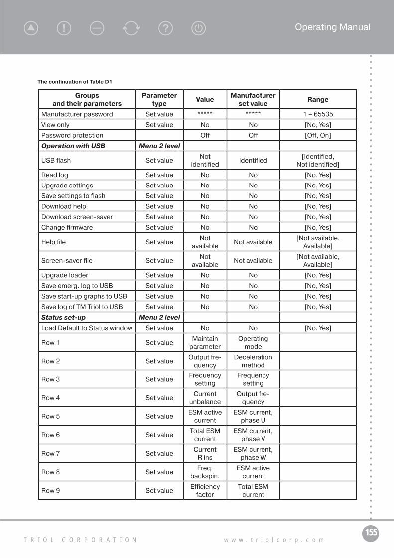
155T R I O L C O R P O R A T I O N w w w . t r i o l c o r p . c o m
Operating Manual
Groups and their parameters
Parameter type
ValueManufacturer
set valueRange
Manufacturer password Set value ***** ***** 1 – 65535
View only Set value No No [No, Yes]
Password protection Off Off [Off, On]
Operation with USB Menu 2 level
USB flash Set valueNot
identified Identified
[Identified, Not identified]
Read log Set value No No [No, Yes]
Upgrade settings Set value No No [No, Yes]
Save settings to flash Set value No No [No, Yes]
Download help Set value No No [No, Yes]
Download screen-saver Set value No No [No, Yes]
Change firmware Set value No No [No, Yes]
Help file Set valueNot
available Not available
[Not available, Available]
Screen-saver file Set valueNot
available Not available
[Not available, Available]
Upgrade loader Set value No No [No, Yes]
Save emerg. log to USB Set value No No [No, Yes]
Save start-up graphs to USB Set value No No [No, Yes]
Save log of TM Triol to USB Set value No No [No, Yes]
Status set-up Menu 2 level
Load Default to Status window Set value No No [No, Yes]
Row 1 Set valueMaintain
parameterOperating
mode
Row 2 Set valueOutput fre-
quency Deceleration
method
Row 3 Set valueFrequency
setting Frequency
setting
Row 4 Set valueCurrent
unbalance Output fre-
quency
Row 5 Set valueESM active
current ESM current,
phase U
Row 6 Set valueTotal ESM
current ESM current,
phase V
Row 7 Set valueCurrent
R insESM current,
phase W
Row 8 Set valueFreq.
backspin. ESM active
current
Row 9 Set valueEfficiency
factor Total ESM
current
The continuation of Table D1

156А Т . 6 5 4 2 2 6 . 2 4 2 - 3 2 O M
Groups and their parameters
Parameter type
ValueManufacturer
set valueRange
Row 10 Set value Load factorFreq.
backspin.
Row 11 Set valueRS input voltage
Underload set value
Row 12 Set valueST input voltage
Load factor
Row 13 Set valueTR input voltage
Overload set value
Row 14 Set valueIn. voltage
unbal. Rotation direction
Row 15 Set valueIntake
Pressure No displayed
Row 16 Set valueCompensa-tor pressure
No displayed
Row 17 Set valueAmb. Tem-
peratureNo displayed
Row 18 Set valueESM oil
TemperatureNo displayed
Row 19 Set value XY vibration No displayed
Row 20 Set value Z vibration No displayed
Row 21 Set value No displayed No displayed
Row 22 Set value No displayed No displayed
Row 23 Set value No displayed No displayed
Row 24 Set value No displayed No displayed
Row 25 Set value No displayed No displayed
Row 26 Set value No displayed No displayed
Row 27 Set value No displayed No displayed
Row 28 Set value No displayed No displayed
Row 29 Set value No displayed No displayed
Row 30 Set value No displayed No displayed
Row 31 Set value No displayed No displayed
Row 32 Set value No displayed No displayed
ACS set-up Menu 2 level
664 Protocol Set value Triol Triol
[Triol, Region, Telescope, Salym Pet, GasPromHantos, CIS,
ASU TNK, ADKU]
399 Exchange rate Set value 115.2 kB 9.6 kB
[2.4 kB, 4.8 kB, 9.6 kB, 19.2 kB,
38.4 kB, 57.6 kB, 76.8 kB, 115.2 kB]
The continuation of Table D1

157T R I O L C O R P O R A T I O N w w w . t r i o l c o r p . c o m
Operating Manual
Groups and their parameters
Parameter type
ValueManufacturer
set valueRange
398 Network address Set value 1 1 1 – 254
StopBit Set value 1 1 1 – 2
Simulation mode Set value Off Off [Off, On]
Manual start-stop Set value Off Off [Off, On]
Answer delay Set value 5 ms 5 ms 0 ms – 200 ms
Modem used Set value Not used Not used [Not used, Used]
Modem identified Set valueNot
identified Identified
[Identified, Not identified]
Adjuster № Set value 1 1 1 – 5
Country and operator code Set value 0 999 0 – 65535
Telephone number Set value 0 0
Resolution of pressure Set value 0.01 1 [0.01, 1]
Display set-up Menu 2 level
Nos. display Set value Yes Yes [No, Yes]
Text scrolling Set value Yes Yes [No, Yes]
Menu scrolling Set value Yes Yes [No, Yes]
Accelerated editing Set value Yes Yes [No, Yes]
Contrast Set value 20 % 0 % -50 % – 50 %
LCD temp. comp. Set value Off Off [Off, On]
Set value confirmation request Set value No No [No, Yes]
LCD voltage (t=-10°C) Set value 21.0 V 21.0 V 10.0 V – 25.0 V
LCD voltage (t=-0°C) Set value 19.6 V 19.6 V 10.0 V – 25.0 V
LCD voltage (t=+25°C) Set value 19.0 V 19.0 V 10.0 V – 25.0 V
LCD voltage (t=+40°C) Set value 18.3 V 18.3 V 10.0 V – 25.0 V
LCD current voltage Set value 20.1 V 0.0 V 0.0 V – 30.0 V
Case temp. Set value 41.1 °С 0.0 °С -100.0 °С ... 100.0 °С
Case temp.2 Set value 31.39 °С 0.00 °С -100.00 °С ... 100.00 °С
Setting universal time Menu 2 level
Time Set value15.04.1970
23:46:59 15.04.1970
16:12:48
681 Winter/Summer time Set value Off Off [Off, On]
Time Set value Summer Summer [Summer, Winter]
Load factory settings Set value No No [No, Yes]
Statistics Menu 2 level
380 ESM oper. Time Set value 97:34:58 91:01:20
380 ESM downtime Set value 297:02:38 291:16:16
383 Number of starts Set value 202 0 0 – 9999
The continuation of Table D1

158А Т . 6 5 4 2 2 6 . 2 4 2 - 3 2 O M
Groups and their parameters
Parameter type
ValueManufacturer
set valueRange
638 Overload stop num Set value 0 0 0 – 9999
639 Underload stop num Set value 1 0 0 – 9999
640 Other prot. stop num Set value 67 0 0 – 9999
Counters Set value Do not clear Do not clear [Do not clear, Clear]
Total operating time Set value 394:37:35 382:17:36
Energy meter Menu 2 level
Energy meter Set value Used Not used [Not used, Used]
Act. energy from reset Set value 275.4 kW*h 0 kW*h
React. energy from reset Set value 17 kvar*h 0 kvar*h
PrecedDayActEnergy Set value 277.9 kW*h 0 kW*h
PrecedDayReactEnergy Set value 5 kvar*h 0 kvar*h
Act. energy for the day Set value 0 kW*h 0 kW*h
React. energy for the day Set value 0 kvar*h 0 kvar*h
653 Energy meter Set value Do not clear Do not clear [Do not clear, Clear]
Energy meter Parameters Menu 2 level
Current sensor factor Set value 1 1 1 – 32767
Voltage divider factor Set value 1 1 1 – 32767
Line frequency Set value 0 Hz 0 Hz 0 Hz – 32767 Hz
Input efficiency factor Set value 0.000 0 0.000 – 1.000
Phase R efficiency factor Inform. 0.000 0 0.000 – 32.767
Phase S efficiency factor Inform. 0.000 0 0.000 – 32.767
Phase T efficiency factor Inform. 0.000 0 0.000 – 32.767
Total in. power Inform. 0.0 kVA 0.0 kVA 0.0 kVA – 3276.7 kVA
Active in. power Inform. 0.0 kW 0.0 kW 0.0 kW – 3276.7 kW
Phase R active power Inform. 0.0 kW 0.0 kW 0.0 kW – 3276.7 kW
Phase S active power Inform. 0.0 kW 0.0 kW 0.0 kW – 3276.7 kW
Phase T active power Inform. 0.0 kW 0.0 kW 0.0 kW – 3276.7 kW
Phase R reactive power Inform. 0.0 kvar 0.0 kvar 0.0 kvar – 3276.7 kvar
Phase S reactive power Inform. 0.0 kvar 0.0 kvar 0.0 kvar – 3276.7 kvar
Phase T reactive power Inform. 0.0 kvar 0.0 kvar 0.0 kvar – 3276.7 kvar
Phase R input voltage Inform. 0.0 V 0.0 V 0.0 V – 3276.7 V
Phase S input voltage Inform. 0.0 V 0.0 V 0.0 V – 3276.7 V
Phase T input voltage Inform. 0.0 V 0.0 V 0.0 V – 3276.7 V
RS input voltage Inform. 0.0 V 0.0 V 0.0 V – 3276.7 V
ST input voltage Inform. 0.0 V 0.0 V 0.0 V – 3276.7 V
TR input voltage Inform. 0.0 V 0.0 V 0.0 V – 3276.7 V
Phase R voltage harmonic factor Inform. 0.00 % 0.00 % 0.00 % – 327.67 %
The continuation of Table D1

159T R I O L C O R P O R A T I O N w w w . t r i o l c o r p . c o m
Operating Manual
Groups and their parameters
Parameter type
ValueManufacturer
set valueRange
Phase S voltage harmonic factor Inform. 0.00 % 0.00 % 0.00 % – 327.67 %
Phase T voltage harmonic factor Inform. 0.00 % 0.00 % 0.00 % – 327.67 %
Phase R current harmonic factor Inform. 0.00 % 0.00 % 0.00 % – 327.67 %
Phase S current harmonic factor Inform. 0.00 % 0.00 % 0.00 % – 327.67 %
Phase T current harmonic factor Inform. 0.00 % 0.00 % 0.00 % – 327.67 %
VSD parameters Menu 2 level
VSD type Set value 0 0 0 – 65535
VSD serial No. Set value 0 0
VSD manufacture date Set value01.01.2001
00:00:00 01.01.2001
00:00:00
VSDC parameters Menu 2 level
VSDC serial No. 0 0
VSDC manufacture date Set value01.01.2001
00:00:00 01.01.2001
00:00:00
VSDC software install date Set value26.10.2012
10:10:44 26.10.2012
17:29:36
386 VSDC software version Set value 31.61 31.61 0.00 – 655.35
Subversion Number Set value 0.00 0 0.00 – 99.99
703 Drive software version Set value 37.044 0 0.000 – 9.999
VSDC software CRC Set value 24406 0 0 – 65535
Soft integrity Set value No No [No, Yes]
Drive software CRC Set value 18452 0 0 – 65535
Drive type Set value AK06-28L AK-06
[AK-06, AK-02_AС11, AK-01_AS30, AK-
02_AS30, AK-06-28, Toshiba, AK06-28,
AK06-28L, Orion-03, Orion-02_AС11, Orion-01_AS30, Orion-02_AS30,
Orion-03-28, Orion-Toshiba, Orion03-28,
Orion03-28L]
Toggle switch Set value Not used Not used [Not used, Used]
Language (Язык) Set valueRussian
(Русский) Russian
(Русский) [Russian (Русский),
English (Англ.)]
Event log Menu 1 level
Viewing mode set-up Menu 2 level
Viewing Starts/Stops Set value Yes Yes [No, Yes]
Viewing emergency trip Set value Yes Yes [No, Yes]
The continuation of Table D1
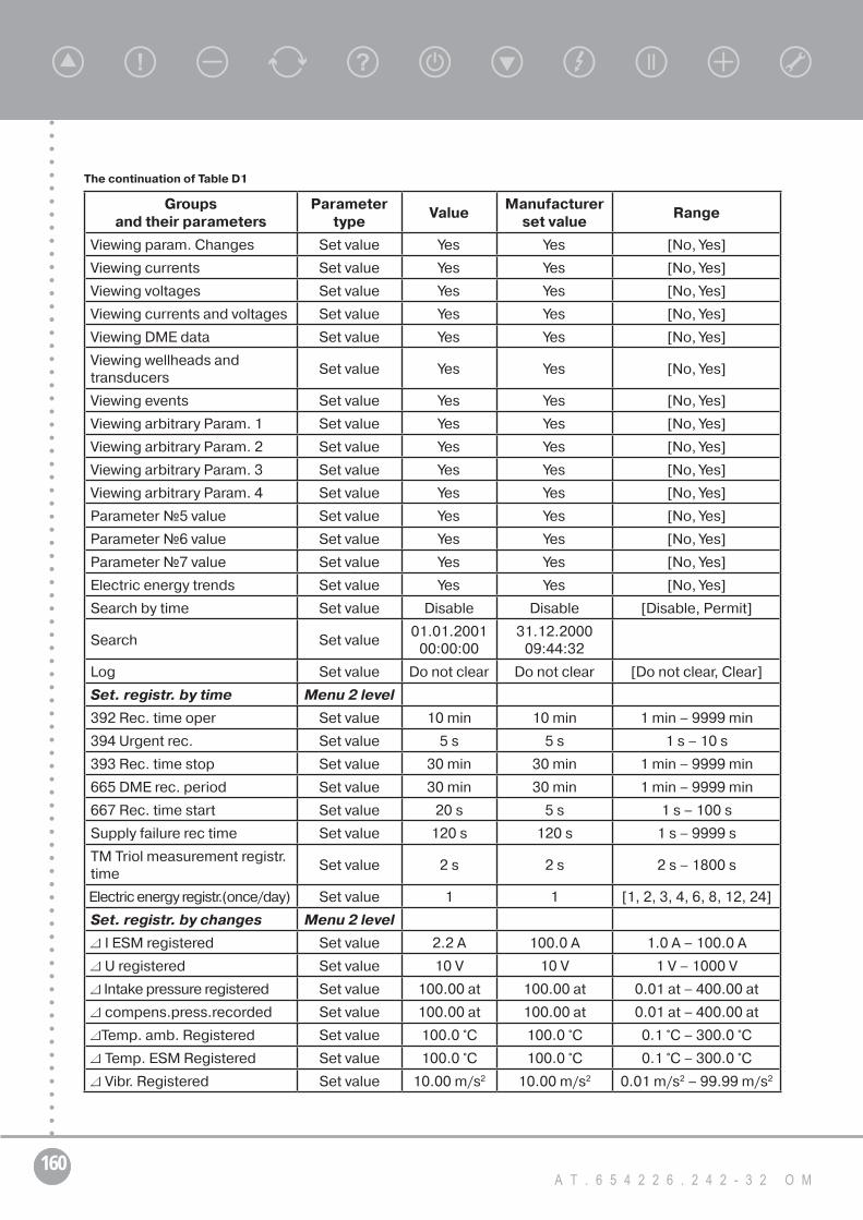
160А Т . 6 5 4 2 2 6 . 2 4 2 - 3 2 O M
Groups and their parameters
Parameter type
ValueManufacturer
set valueRange
Viewing param. Changes Set value Yes Yes [No, Yes]
Viewing currents Set value Yes Yes [No, Yes]
Viewing voltages Set value Yes Yes [No, Yes]
Viewing currents and voltages Set value Yes Yes [No, Yes]
Viewing DME data Set value Yes Yes [No, Yes]
Viewing wellheads and transducers
Set value Yes Yes [No, Yes]
Viewing events Set value Yes Yes [No, Yes]
Viewing arbitrary Param. 1 Set value Yes Yes [No, Yes]
Viewing arbitrary Param. 2 Set value Yes Yes [No, Yes]
Viewing arbitrary Param. 3 Set value Yes Yes [No, Yes]
Viewing arbitrary Param. 4 Set value Yes Yes [No, Yes]
Parameter №5 value Set value Yes Yes [No, Yes]
Parameter №6 value Set value Yes Yes [No, Yes]
Parameter №7 value Set value Yes Yes [No, Yes]
Electric energy trends Set value Yes Yes [No, Yes]
Search by time Set value Disable Disable [Disable, Permit]
Search Set value01.01.2001
00:00:00 31.12.2000
09:44:32
Log Set value Do not clear Do not clear [Do not clear, Clear]
Set. registr. by time Menu 2 level
392 Rec. time oper Set value 10 min 10 min 1 min – 9999 min
394 Urgent rec. Set value 5 s 5 s 1 s – 10 s
393 Rec. time stop Set value 30 min 30 min 1 min – 9999 min
665 DME rec. period Set value 30 min 30 min 1 min – 9999 min
667 Rec. time start Set value 20 s 5 s 1 s – 100 s
Supply failure rec time Set value 120 s 120 s 1 s – 9999 s
TM Triol measurement registr. time
Set value 2 s 2 s 2 s – 1800 s
Electric energy registr.(once/day) Set value 1 1 [1, 2, 3, 4, 6, 8, 12, 24]
Set. registr. by changes Menu 2 level
ΔI ESM registered Set value 2.2 A 100.0 A 1.0 A – 100.0 A
ΔU registered Set value 10 V 10 V 1 V – 1000 V
Δ Intake pressure registered Set value 100.00 at 100.00 at 0.01 at – 400.00 at
Δcompens.press.recorded Set value 100.00 at 100.00 at 0.01 at – 400.00 at
ΔTemp. amb. Registered Set value 100.0 °С 100.0 °С 0.1 °С – 300.0 °С
ΔTemp. ESM Registered Set value 100.0 °С 100.0 °С 0.1 °С – 300.0 °С
ΔVibr. Registered Set value 10.00 m/s2 10.00 m/s2 0.01 m/s2 – 99.99 m/s2
The continuation of Table D1

161T R I O L C O R P O R A T I O N w w w . t r i o l c o r p . c o m
Operating Manual
Groups and their parameters
Parameter type
ValueManufacturer
set valueRange
ΔPannulus registered Set value 100.00 at 100.00 at 0.01 at – 400.00 at
ΔPbuff registered Set value 100.00 at 100.00 at 0.01 at – 400.00 at
ΔPline registered Set value 100.00 at 100.00 at 0.01 at – 400.00 at
ΔLevel annulus registered Set value 1000 m 1000 m 1 m – 9999 m
ΔAdd. Ain1. registered Set value 100 m3/h 1000 0.1 m3/h – 6553.5 m3/h
ΔAdd. Ain2. registered Set value 100 V 1000 0.1 V – 6553.5 V
Set. registr. custom Menu 2 level
Parameter №1 Set value No displayed No displayed
Parameter №2 Set value No displayed No displayed
Parameter №3 Set value No displayed No displayed
Parameter №4 Set value No displayed No displayed
Parameter №5 Set value No displayed No displayed
Parameter №6 Set value No displayed No displayed
Parameter №7 Set value No displayed No displayed
ΔParameter №1 registered Inform. 1000 1000 1 – 1000
ΔParameter №2 registered Inform. 1000 1000 1 – 1000
ΔParameter №3 registered Inform. 1000 1000 1 – 1000
ΔParameter №4 registered Inform. 1000 1000 1 – 1000
ΔParameter №5 registered Inform. 1000 1000 1 – 1000
ΔParameter №6 registered Inform. 1000 1000 1 – 1000
ΔParameter №7 registered Inform. 1000 1000 1 – 1000
The continuation of Table D1

162А Т . 6 5 4 2 2 6 . 2 4 2 - 3 2 O M
Table D2 — Values of the relative given measurement error for the measured parameters
Measured parameterRange of measurable values
with a preset accuracy
Relative reduced accu-racy of measurement, no
more than, %
018 RS input voltage 190–515 V 2,4 %
019 ST input voltage 190–515 V 2,4 %
020 TR input voltage 190–515 V 2,4 %
Iout VSD phase U 30 – 110 %* 2,3 %
Iout VSD phase V 30 – 110 %* 2,3 %
Iout VSD phase W 30 – 110 %* 2,3 %
004 ESM current, phase U As per VSD current** 2,5 %
005 ESM current, phase V As per VSD current ** 2,5 %
006 ESM current, phase W As per VSD current** 2,5 %
115 R ins Protection 1000 – 100000 Ohm 2,5 %
505 Total ESM current As per VSD current** 2,5 %
701 ESM active current As per VSD current** 2,5 %
040 Intake Pressure (0–10 V) 0,3–10 V 2,5 %
040 Intake Pressure (0–5 mA) 0,1–5 mA 2,3 %
040 Intake Pressure (4–20 mA) 4,5–20 mA 2,5 %
563 Compensator pressure (0–10 V) 0,3–10 V 2,5 %
563 Compensator pressure (0–5 mA) 0,1–5 mA 2,3 %
563 Compensator pressure (4–20 mA) 4,5–20 mA 2,5 %
573 Amb. temperature (0–10 V) 0,3–10 V 2,5 %
573 Amb. temperature (0–5 mA) 0,1–5 mA 2,3 %
573 Amb. temperature (4–20 mA) 4,5–20 mA 2,5 %
042 XY Vibration (0–10 V) 0,3–10 V 2,3 %
042 XY Vibration (0–5 mA) 0,1–5 mA 2,3 %
042 XY Vibration (4–20 mA) 4,5–20 mA 2,5 %
043 Z Vibration (0–10 V) 0,3–10 V 2,5 %
043 Z Vibration (0–5 mA) 0,1–5 mA 2,3 %
043 Z Vibration (4–20 mA) 4,5–20 mA 2,5 %
044 Annulus pressure (0–10 V) 0,3–10 V 2,5 %
044 Annulus pressure (0–5 mA) 0,1–5 mA 2,3 %
044 Annulus pressure (4–20 mA) 4,5–20 mA 2,5 %
041 ESM oil temperature (0–10 V) 0,3–10 V 2,5 %
041 ESM oil temperature (0–5 mA) 0,1–5 mA 2,3 %
041 ESM oil temperature (4–20 mA) 4,5–20 mA 2,5 %
045 Wellhead pressure (0–10 V) (Buffer pressure)
0,3–10 V 2,5 %
045 Wellhead pressure (0–5 mA) 0,1–5 mA 2,3 %

163T R I O L C O R P O R A T I O N w w w . t r i o l c o r p . c o m
Operating Manual
Measured parameterRange of measurable values
with a preset accuracy
Relative reduced accu-racy of measurement, no
more than, %
045 Wellhead pressure (4–20 mA) 4,5–20 mA 2,5 %
046 Flow line pressure (0–10 V) 0,3–10 V 2,5 %
046 Flow line pressure (0–5 mA) 0,1–5 mA 2,3 %
046 Flow line pressure (4–20 mA) 4,5–20 mA 2,5 %
047 Annulus level (0–10 V) 0,3–10 V 2,5 %
047 Annulus level (0–5 mA) 0,1–5 mA 2,3 %
047 Annulus level (4–20 mA) 4,5–20 mA 2,5 %
If a digital telemetry system is used, reduced accuracy of measurements is subject to the specification of the system used.
* — The VSD currents shall be preliminarily calibrated under the VSD rated load ± 15%, load currents shall be fixed and vary by no more than 1% within 60 sec.
** — Provided that the VSD loading at such ESM current is 30-110% of the VSD rated load, and VSD has been calibrated at currents close to the VSD rated ones.
The continuation of Table D2

164А Т . 6 5 4 2 2 6 . 2 4 2 - 3 2 O M
Appendix Е(normative)
Table of voltage losses values
Table E — Voltage losses values
Voltage losses in cables with 3x16 mm copper
conductors, V (per 1000 meters)
Voltage losses in cables with 3x21 mm copper
conductors, V (per 1000 meters)
Voltage losses in cables with 3x25 mm copper
conductors, V (per 1000 meters)
Voltage losses in cables with 3x33 mm copper
conductors, V (per 1000 meters)
ESMIrated,
A
Stratum temperature, oC
ESMIrated,
A
Stratum temperature, oC
ESMIrated,
A
Stratum temperature, oC
ESMIrated,
A
Stratum temperature, oC
40-70 70-100 >100 40-70 70-100 >100 40-70 70-100 >100 40-70 70-100 >100
14,6 28 32 35 14,6 21 24 27 14,6 18 20 23 14,6 13 16 17
18 34 39 44 18 26 30 33 18 22 25 28 18 17 19 21
21 40 46 51 21 31 35 39 21 26 29 33 21 19 22 25
22 42 48 53 22 32 37 41 22 27 31 34 22 20 23 26
24 46 .53 58 24 35 40 45 24 29 34 37 24 22 26 28
25 48 55 61 25 37 42 46 25 31 35 39 25 23 27 29
26 50 57 63 26 38 43 48 26 32 36 40 26 24 28 31
27 51 59 66 27 39 45 50 27 33 38 42 27 25 29 32
28 53 61 68 28 41 47 52 28 34 39 44 28 26 30 33
29 55 64 70 29 42 48 54 29 35 41 45 29 27 31 34
30 57 66 73 30 44 50 56 30 37 42 47 30 28 32 35
32 61 70 78 32 47 53 59 32 39 45 50 32 29 34 38
33 63 72 80 33 48 55 61 33 40 46 51 33 30 35 39
34 65 74 83 34 50 57 63 34 42 47 53 34 31 36 40
35 67 77 85 35 51 58 65 35 43 49 54 35 32 37 41
36 69 79 87 36 53 60 67 36 44 50 56 36 33 38 42
37 70 81 90 37 54 62 69 37 45 52 58 37 34 39 43
38 72 83 92 38 55 63 71 38 46 53 59 38 35 40 45
39 74 85 95 39 57 65 72 39 48 54 61 39 36 41 46
40 76 88 97 40 58 67 74 40 49 56 62 40 37 43 47
41 78 90 100 41 60 68 76 41 50 57 64 41 38 44 48
42 80 92 102 42 61 70 78 42 51 59 65 42 39 45 49
43 82 94 104 43 63 72 80 43 53 60 67 43 40 46 51
44 84 96 107 44 64 73 82 44 54 61 68 44 41 47 52
47 90 103 114 47 69 78 87 47 57 66 73 47 43 50 55
48 91 105 117 48 70 80 89 48 59 67 75 48 44 51 56
49 93 107 119 49 72 82 91 49 60 68 76 49 45 52 58
51 97 112 124 51 74 85 95 51 62 71 79 51 47 54 60
53 101 116 129 53 77 88 98 53 65 74 82 53 49 56 62

165T R I O L C O R P O R A T I O N w w w . t r i o l c o r p . c o m
Operating Manual
The continuation of Table E
Voltage losses in cables with 3x16 mm copper
conductors, V (per 1000 meters)
Voltage losses in cables with 3x21 mm copper
conductors, V (per 1000 meters)
Voltage losses in cables with 3x25 mm copper
conductors, V (per 1000 meters)
Voltage losses in cables with 3x33 mm copper
conductors, V (per 1000 meters)
ESMIrated,
A
Stratum temperature, oC
ESMIrated,
A
Stratum temperature, oC
ESMIrated,
A
Stratum temperature, oC
ESMIrated,
A
Stratum temperature, oC
40-70 70-100 >100 40-70 70-100 >100 40-70 70-100 >100 40-70 70-100 >100
55 105 120 134 55 80 92 102 55 67 77 86 55 51 58 65
56 107 123 136 56 82 93 104 56 68 78 87 56 52 60 66
57 109 125 138 57 83 95 106 57 70 80 89 57 52 61 67
58 110 127 141 58 85 97 108 58 71 81 90 58 53 62 68
59 112 129 143 59 86 98 110 59 72 82 92 59 54 63 69
60 114 131 146 60 88 100 111 60 73 84 93 60 55 64 70
61 116 134 148 61 89 102 113 61 75 85 95 61 56 65 72
62 118 136 151 62 91 103 115 62 76 87 96 62 57 66 73
63 120 138 153 63 92 105 117 63 77 88 98 63 58 67 74
64 122 140 155 64 93 107 119 64 78 89 100 64 59 68 75
65 124 142 158 65 95 108 121 65 79 91 101 65 60 69 76
67 128 147 163 67 98 112 124 67 82 94 104 67 62 71 79
69 131 151 168 69 101 115 128 69 84 96 107 69 64 73 81
72 137 158 175 72 105 120 134 72 88 101 112 72 66 77 85
73,5 140 161 179 73,5 107 123 137 73,5 90 103 114 73,5 68 78 86
77,5 148 170 188 77,5 113 129 144 77,5 95 108 121 77,5 71 82 91
78,5 150 172 191 78,5 115 131 146 78,5 96 110 122 78,5 72 83 92
81 154 177 197 81 118 135 150 81 99 113 126 81 75 86 95
82 156 180 199 82 120 137 152 82 100 115 128 82 75 87 96
86,5 165 189 210 86,5 126 144 161 86,5 106 121 135 86,5 80 92 102
88 168 193 214 88 129 147 163 88 108 123 137 88 81 94 103
90,5 172 198 220 90,5 132 151 168 90,5 111 126 141 90,5 83 96 106
98 187 215 238 98 143 163 182 98 120 137 152 98 90 104 115
99 189 217 240 99 145 165 184 99 121 138 154 99 91 105 116
104 198 228 253 104 152 173 193 104 127 145 162 104 96 111 122
131 250 287 318 131 191 218 243 131 160 183 204 131 121 139 154
178 339 390 432 178 260 297 331 178 218 249 277 178 164 189 209

166А Т . 6 5 4 2 2 6 . 2 4 2 - 3 2 O M
Appendix F(normative)
Modem Fargo 100 Maestro instruction
F.1. Modem description
Maestro 100 is finished GSM modem for transfer of voice, data, fax and SMS messages. Also modem supports GPRS mode class 10 for rapid data transfer. Modem operates by means of AT commands in all modes. Modem adjusting and setting performs through RS232 (9 outputs, Fig. F.1.)
Ejector button for extracting SIM card holder
Connector for antenna attachment
Conditionindicator 15-pin Sub-D female connector
(serial and audio inputs)
4-PIN power connectorSIM card holder
Figure F.1— Modem description
F.1.1. Condition indicatorLED on a front modem panel shows modem condition:• Off — modem is off;• On — modem is connected to the power supply;• Flashing slowly — modem is on a standby mode;• Flashing abruptly — modem is on a data transfer mode (only GSM).F.1.2. Antenna pin connectorIt connects with pug-in connector of external antenna. Make sure that antenna is intended for
900/1800 MHz frequency range, insulation 50 Ohm and tight.F.1.3. 15-pin D-SUB female connector (RS232/Audio) is shown in Fig. F.2.Connector provides serial connection and audio connection of the modem.
Figure F.2 — Specification of D-SUB female connector

167T R I O L C O R P O R A T I O N w w w . t r i o l c o r p . c o m
Operating Manual
Table F.1 — 15-pin D-SUB female connector
Pin number Name EIA designation Type Note
1 DCD Data Carrier Detect Output
2 TX Transmit Data Input
3 BOOT Input Not used
4 MICROPHONE (+) Input
5 MICROPHONE (-) Input
6 RX Receive Data Output
7 DSR Date Set Ready Output
8 DTR Data Terminal Ready Input
9 GND Ground Ground
10 SPEAKER (+) Output
11 CTS Clear to Send Output
12 RTS Request to Send Input
13 RI Ring Indicator Output
14 RESET Input Pull low
15 SPEAKER (-) Output
F.1.4. Power supply PIN
Figure F.3 — Power supply connector
Table F.2 — Assignment of power supply connector pins
Pin number Name Functions
1 I/O Input/output
2 ~INTRsynchronizable output of interruptions, low active level (ground); reserved for additional functions
3 POWER (-) DC power negative input
4 POWER (+) DC power positive input

168А Т . 6 5 4 2 2 6 . 2 4 2 - 3 2 O M
Power cable must be used from supply complement.
Connector Micro-Fit 3.0 Fuse holder, fuse rating: 250 V - 2,5 A
Stripped wire
5-32 V DC Supply
Figure F.4 — Connection scheme
Table F.3 — Voltage levels
Parameters Min Standard Max Note
I/O
I/O low level 0 0.5 V
I/O high level 3 V 5 V
I/O current load 10 mA
INTR
Low level 0 0.5 VActive level is low (ground) otherwise leave it open modem damaging
F.1.5. Installing the SIM cardUse a ball pen or paper clip to eject the SIM holder by pressing the eject button. Put the SIM card to
the tray; make sure it is completely inserted in the tray, then carefully put back the tray into the slot.DO NOT pull out the SIM holder without pushing the ejector button. It may damage modem.F.1.6. Connecting the external antennaMake sure that antenna is intended for impedance 50 Ohm and frequency range 900/1800 MHz. Attach
antenna male connector to the socket as shown in Fig. F.5.F.1.7. Connection to the power supply
Male connector of the antenna cable
Figure F.5 — Connection diagram
Connect power cable with stripped wires as shown in Fig. F.6. Use following parameters for cable selection:• Power supply voltage — from 5 В to 32 V DC;• Rated current — 650 mA.

169T R I O L C O R P O R A T I O N w w w . t r i o l c o r p . c o m
Operating Manual
Figure F.6 — Connection diagram
F.2. Modem connecting to PC
Maestro 100 15 pin SUB-D connector Connector DB.9
RS-232 port PCFigure F.7 — Connection diagram
F.2.1. For modem connection through COM-232 to PC:1. Cable DB9F/HD15M (for connecting through COM-232);2. Power supply unit 5 – 32 V;3. Installed PC driver FTDI;4. Modem in operating condition;5. GSM antenna;6. SIM card of mobile operator;7. Installed PC actual service software version.
F.2.2. For modem connection through AUSB to PC:1. Cable DB9F/HD15M;2. USB cable type A — type B;3. AUSB unit;4. Power supply unit 5 – 32 V;5. Installed PC driver FTDI;6. Modem in operating condition;7. SIM card of mobile operator;8. Installed PC actual service software version.
F.2.3. For connection through USB:1. Interface converter cable USB/RS232 (HD15M);2. Power supply unit 5 – 32 V;3. Installed PC driver FTDI;4. Modem in operating condition;5. SIM card of mobile operator;6. Installed PC actual service software version.
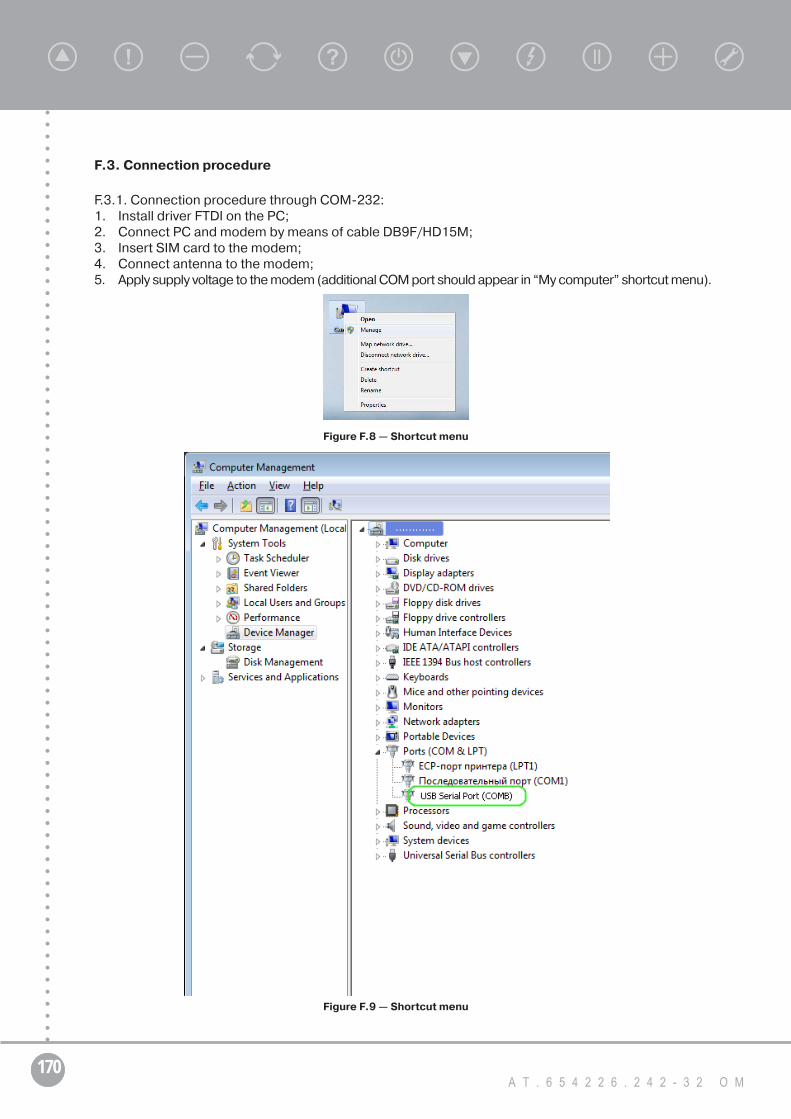
170А Т . 6 5 4 2 2 6 . 2 4 2 - 3 2 O M
F.3. Connection procedure
F.3.1. Connection procedure through COM-232:1. Install driver FTDI on the PC;2. Connect PC and modem by means of cable DB9F/HD15M;3. Insert SIM card to the modem;4. Connect antenna to the modem;5. Apply supply voltage to the modem (additional COM port should appear in “My computer” shortcut menu).
Figure F.8 — Shortcut menu
Figure F.9 — Shortcut menu

171T R I O L C O R P O R A T I O N w w w . t r i o l c o r p . c o m
Operating Manual
F.3.2. Connection procedure through AUSB unit:1. Install driver FTDI on the PC;2. Connect PC and AUSB unit of type A or B;3. Connect modem and AUSB unit by means of cable DB9F/HD15M;4. Insert SIM card to the modem;5. Connect antenna to the modem;6. Apply supply voltage to the modem.
F.3.3. Connection procedure through USB:1. Install driver FTDI on the PC;2. Connect PC and modem by means of interface converter USB/HD15M;3. Insert SIM card to the modem;4. Connect antenna to the modem;5. Apply supply voltage to the modem.
F.4 Operation start with modem
F.4.1 1 Operation with modem from the UMKA-03 side:1. Enter UMKA-03 “System/ACS set-up” menu;2. Choose: “664 Protocol” — “Triol”;3. Choose: “399 Exchange rate” — “115,2 kB”;4. Choose: “Modem used” — “Used”;5. “Identified” will appear in Modem string after applying of changes.
Figure F.10 — Controller UMKA-03 menu
F.4.2. Operation with modem from service software side:1. Enter menu “Settings”;2. Choose COM port number for modem connection;
Figure F.11 — Service software UMKA settings menu

172А Т . 6 5 4 2 2 6 . 2 4 2 - 3 2 O M
3. Choose phone number of the inserted SIM card in format +************ (Country code, operator code, subscriber number), there are no spaces, brackets and hyphens. If list is empty, click “Add contact”.
Figure F.12 — Service software UMKA settings menu
Click button “Add contact” and add VSD number to the list.
Figure F.13— Service software UMKA settings menu
4. Entering a new number:• enter modem number and addition information in fields;• click button “Add”;• click button “Confirm”.
5. Edit old number:• select table row;• edit data in fields;• click button “Edit” etc.;• click button “Confirm”.
6. Data deleting:• select table row which is editing;• click button “Delete” etc.;• click button “Confirm”.
7. Canceling:• click button “Cancel”.

173T R I O L C O R P O R A T I O N w w w . t r i o l c o r p . c o m
Operating Manual
Figure F.14 — Service software UMKA settings menu
Click button “Confirm” for modem list changes applying (for saving all changes the same).
Click button for connection between modem and VSD by set number. Password entering field will appear.
Figure F.15 — «Enter access password» window
“Incorrect password” message will appear after entering wrong password.
Figure F.16 — «Incorrect password» window
“Wait ... second. Modem is connecting” message will appear after entering right password.
Figure F.17 — «Enter access password» window
“Modem doesn’t answer” message will appear if modem is out of order, incorrect modem connection, wrong COM port number in settings.
Figure F.18 — «Modem doesn’t answer» window
If modem connected, software interrogate signal power and money balance.

174А Т . 6 5 4 2 2 6 . 2 4 2 - 3 2 O M
Software adjusts base parameter setting of connection. Failure is possible at this operations.“Modem settings isn’t set” message appears then and there is no possibility for further connection.Software starts connection between modem and VSD if there are no issues.“Connection isn’t established. Check number and modem connection of VSD” message appears
if following events happened:• modem is out of order;• modem is off;• connection parameters aren’t set in UMKA-03 menu (Fig. F.10).Otherwise “Connection is established” message appears.
8. Buttons will be active — after call. This means that connection has been established.
F.5. Remote VSD operation
F.5.1. Current controller condition (table):
1. Click button after connection establishing;2. Table of current controller condition will appear on the display (Fig. F.22).
Figure F.22 — «Current controller condition» window
F.5.2. Current controller condition (graph):
1. Click button after connection establishing;2. Current controller condition will appear on the display in graphical view.

175T R I O L C O R P O R A T I O N w w w . t r i o l c o r p . c o m
Operating Manual
Figure F.23 — “Current controller condition” window
F.5.3. Reading/recording of controller presets:
1. Click button after connection establishing;2. Current table of VSD presets will appear on the display;
3. Click button for preset reading from the controller;
4. Click button for preset recording into the controller;
5. Click button for preset recover.
Figure F.24 — Current preset value of the VSD
F.5.4. Reading from the controller event log:
1. Click button after establishing of connection;2. Operation with controller window will open;
3. Click button for reading event log;4. Time setting is possible in the tab «Time synchronization».

176А Т . 6 5 4 2 2 6 . 2 4 2 - 3 2 O M
Figure F.25 — Operation with controller
F.6. Session ending
Click button for session interrupting after remote control finishing.If connection lost «Modem and VSD connection is failed. Connection lost» message appears.Modem connection interrupts after set time during operation with windows or tables of presets
when parameter “GSM connection blocking after time (1 – 180 minutes)” is set. “Allowable time ended. Session ended” message appears.
«Event log has been read. Session ended» message appears after event log reading.
F.7. Troubleshooting
F.7.1. The modem’s LED does not light:• check if the external power has been properly connected to the modem;• check if the power connector is properly inserted;• check the fuse in the power cord.
F.7.2. The modem’s LED lights but does not blink long time after power up:• check if a valid SIM card has been properly inserted;• check if the SIM card has been locked (refer to AT+CPIN command in AT command guide);• check if the network coverage is available;• make sure that the CTS and DTR pins of the serial port are not connected together.
F.7.3. The modem does not respond to the terminal program:• check if the RS232 cable has been properly connected;• check if your program has proper settings. Factory setting of the modem is:
• 15200 bps;• 8 data bits;• No parity bit;• 1 stop bit 4.

177T R I O L C O R P O R A T I O N w w w . t r i o l c o r p . c o m
Operating Manual
Appendix GList of elements and electric schematic diagram