trials results from the canadian remote … meeting...trials results from the canadian remote...
TRANSCRIPT
Trials Results from the Canadian Remote Minehunting System: Fusion of Bathymetric and Sidescan Sonar Data
Anna Crawford, Mark Trevorrow and David Hopkin Defence Research and Development Canada – Atlantic
Dartmouth, Nova Scotia, Canada, B2Y 3Z7
ABSTRACT
The Defence Research and Development Canada Agency recently completed a three-year Remote Minehunting System Technology Demonstrator Project (RMS TDP). The purpose of this project was to gain technical expertise in semi-submersible-based remote minehunting systems to advise the Canadian Navy on the best way ahead in this area. The research and engineering challenges encompassed by the project were wide-ranging, including for example, Computer Aided Detection and Classification (CAD/CAC), underwater positioning, vehicle/towfish towing stability, high bandwidth communications, operator display and mission planning. At the close of the project, DRDC has an operational system which has been tested in three sea-going trials totalling over 120 mission hours.
Subsequently, in the spring of 2003, a joint Canada-France minehunting trial was held in Brest, France, where in addition to its Klein 5500 sidescan sonar, the system was also fitted with a Reson 8125 bathymetric sonar. The semi-submersible vehicle provides a very stable platform for the bathymetric sonar, and high-quality bathymetric data complimenting the coincident sidescan sonar data was collected over deployed minelike targets and other interesting seabed features. Various possibilities exist for improvement of the RMS performance by integration of the bathymetric data into several aspects of system operation, including target location or identification and the mission planning process.
1.0 INTRODUCTION
Unmanned remotely operated vehicles offer many advantages for minehunting in both safety and efficiency. Defence Research and Development Canada has been involved in a program for the past several years to develop and test a semi-submersible vehicle as a minehunting platform. Compared to surface vessels, a semi-submersible offers greater manoeuvrability and survey speed (typically 8 to 10 knots) with better attitudinal stability in seas and winds. Compared to AUVs, a semi-submersible allows real-time high-bandwidth communication for data transfer both to and from the vehicle and GPS positioning, as well as having greater payload carrying and range-speed capabilities. As a vehicle for sonar survey operations, the sidescan sonar towfish is more easily and safely deployed from the semi-submersible than from a surface vessel and its stability makes it an ideal platform for high-resolution bathymetric sonars. The many advantages of such a system come at the cost, however, of the significant technical challenges which must be overcome.
The three-year Remote Minehunting System Technology Demonstrator Project (RMS TDP) was completed in the spring of 2003 [1,2]. The project encompassed a series of three comprehensive sea-going trials, with associated preparatory work-up trials. During the final two trials, the system logged over 120 hours of survey
RTO-MP-SET-079 11 - 1
Paper presented at the RTO SET Symposium on “Capabilities of Acoustics in Air-Ground and Maritime Reconnaissance, Target Classification and -Identification”, held in Lerici, Italy, 26-28 April 2004, and published in RTO-MP-SET-079.
UNCLASSIFIED/UNLIMITED
UNCLASSIFIED/UNLIMITED

operations, collecting in excess of 60 hours of sidescan sonar survey data. Since the close of the TDP, the RMS stands as a functioning tool for research into minehunting and sonar operations.
Subsequently in June 2003, the system was deployed during a joint Canada-France minehunting trial with researchers from Groupe d'Etudes Sous-Marines de l'Atlantique (GESMA) in Brest Harbour, France. Prior to this trial, a high resolution multibeam bathymetric sonar was installed in the semi-submersible vehicle and both sidescan and bathymetric sonar surveys were conducted over minelike targets and other interesting seabed features.
The purpose of this paper is to give a brief overview of characteristics of the RMS and some examples of results from the joint Canada-France trial. In particular, some possibilities for improving minehunting or route survey effectiveness by incorporating bathymetric survey information have been examined based on the coupled sidescan and bathymetric sonar surveys conducted during the trial.
2.0 OVERVIEW OF THE REMOTE MINEHUNTING SYSTEM
The RMS is comprised of three main parts: the semi-submersible vehicle (Dorado), the Variable Depth Towfish (VDT) and the containerized command-and-control centre (RMTC) which houses the operators and computers on the support vessel. The VDT and Dorado are linked by fibre-optic tow cable and the Dorado and operators via two-way high-bandwidth radio links.
The Dorado vehicle, shown in Figure 1, is a prototype semi-submersible vehicle that has been developed by the Canadian Department of National Defence and manufactured by International Submarine Engineering Research (ISER), in Vancouver, Canada [3]. The vehicle is 8.3 m long with a hull diameter of 1.17 m and weighs 6400 kg fully fuelled. A 5 m surface-piercing mast supports various radio and DGPS antennae, and provides the air-intake for the 260 kW diesel engine. To reduce torque effects, the vehicle is propelled by a counter-rotating propeller system. A 1.5 m deep keel houses the cable winching system for the VDT. Towed sidescan operations in water depths up to 200 m have been performed. The Dorado typically operates at speeds of 8 to 10 knots (maximum 16 knots) at a hull depth of 3.3 m, with maximum range at this speed of 120 nautical miles (220 km). In addition to the diesel engine and hydraulic winching system, onboard the Dorado are GPS, vehicle control and communication processors, navigation and attitude sensors, radio transmitters and receivers, video cameras, sonar processors (sidescan and bathymetric) and other instruments integral to the propulsion and winching systems.
The VDT, also shown in Figure 1, is an actively stabilized towfish which carries a Klein 5500 multibeam sidescan sonar and a suite of inertial navigation sensors. It is also manufactured by ISER. The towfish control surfaces (wings) have a large surface area which is capable of generating enough cable tension to completely immerse the Dorado vehicle – a critical component of the early stages of the project was careful and accurate modelling of the complicated two-body towing dynamics of the system.
The operators, situated in the RMTC on the deck of the support vessel, monitor system performance and sonar data, and if necessary pilot the vehicle, in real-time via radio links between the Dorado and the support vessel. A WiLAN radio link operating at 3.45 GHz is capable of data throughput up to 20 Mbit/s and ranges of up to 7 km. This link carries the data streams from both the bathymetric and sidescan sonars, vehicle attitude and position sensor data required by the bathymetric sonar, and the mast-head and keel cameras. A separate VHF radio-telemetry link is used for vehicle command, control, and status. Typically there are at least two dedicated operators, one monitoring the vehicle systems with override capability (or manually piloting), and
11 - 2 RTO-MP-SET-079
UNCLASSIFIED/UNLIMITED
UNCLASSIFIED/UNLIMITED
Trials Results from the Canadian Remote Minehunting System: Fusion of Bathymetric and Sidescan Sonar Data

one viewing the real-time sidescan sonar data stream. A third operator is required to run the bathymetric sonar system. Watch is kept from the support vessel bridge for boat traffic and obstacle avoidance, in hand-held radio contact with the operators.
In addition to appearing on the real-time sonar display, the incoming sidescan sonar data (and the ancillary sensor data required for geo-referencing) are stored in an Oracle database. Another aspect of the RMS TDP was research into an experimental Computer Aided Detection and Classification (CAD/CAC) system that analyses the sonar data for minesized and minelike objects, with reference to the prior survey data in the database for change detection, and supplies real-time operator alerts on the sonar data console [4].
Figure 1: The Dorado semi-submersible vehicle (yellow) and VDT towfish (silver and white), with Klein 5500 sidescan sonar lowermost, being lifted by crane. The inset shows the vehicle
operating submerged at typical survey speed.
RTO-MP-SET-079 11 - 3
UNCLASSIFIED/UNLIMITED
UNCLASSIFIED/UNLIMITED
Trials Results from the Canadian Remote Minehunting System: Fusion of Bathymetric and Sidescan Sonar Data

The stability of the towing vehicle combined with the active stabilization of the towfish and the multibeam Klein sonar result in superior quality sidescan sonar data. The Dorado vehicle also provides a very good platform for the bathymetric sonar. The centred hull-mounting of the bathymetric sonar transducer effectively minimizes the possibility of moment arm motion artefacts and the vehicle is accurately instrumented for attitude and position [5]. The RMS is able to follow survey routes with high positioning accuracy and minimal end-of-line manoeuvring time.
3.0 POSSIBLE ROLES FOR BATHYMETRIC SONARS IN MINEHUNTING
The joint Canada-France trial has provided complementary sidescan and bathymetric survey results which allow assessment of several possibilities for the use of bathymetric sonars in minehunting or route survey. Some earlier work in this area sponsored in part by the Canadian Department of National Defence indicated that at that time (1997), "multibeam sonars [did] not yet have the resolution required to be used as mine detection sonars" [6,7]. Since that time, significant advances in sonars, attitude and positioning sensors, and computing technologies have led to instruments such as the Reson Seabat 8125 bathymetric sonar. This system is representative of the current state-of-the-art in high resolution multibeam sonars, with 240 beams, each 1° fore-aft by 0.5° athwartships, and range resolution of the order of centimetres along the beams.
The proposed roles which will be discussed in the following sections can be summarized as follows:
1. as part of an initial reconnaissance to provide detailed bathymetric information that can assist route and altitude planning for later sidescan sonar surveys by identifying potentially dangerous slopes, shipwrecks, or mid-water objects.
2. to provide an initial survey for minelike targets that can be confirmed by later sidescan surveys. The hull-mounting of the bathymetric sonar affords more precise positioning of the resulting data products than the towfish-mounted sidescan sonar, so that the multibeam sonar is also especially useful for detecting small bathymetric changes relative to previous surveys.
3. to provide independent information that when fused with sidescan sonar data, can be used to enhance target location ability (for example, correction for seabed slope or improvement of towfish location in the absence of reliable towfish navigation sensors), and potentially to add features for Computer Aided Detection and Classification (CAD/CAC).
4. to provide real-time obstacle and seabed avoidance warnings for the VDT.
Each of these will now be discussed with reference to specific results from the trial.
3.1 Initial Reconnaissance During the trial, two prior bathymetric surveys were effective in planning subsequent sidescan sonar operations over two areas. In both cases, the bathymetric surveys allowed survey route planning in order to maximize efficiency and sidescan survey data quality, as well as to avoid potential hazards to the VDT, in the first case, steep slopes and in the second, the shallow superstructure of a submerged wreck.
11 - 4 RTO-MP-SET-079
UNCLASSIFIED/UNLIMITED
UNCLASSIFIED/UNLIMITED
Trials Results from the Canadian Remote Minehunting System: Fusion of Bathymetric and Sidescan Sonar Data

Figure 2: Partial coverage bathymetry survey chart data over an area outside Brest Harbour. Depths are colour-coded from deepest blue to shallowest red. The grid lines are spaced at 1 km intervals.
Figure 2 shows an overview of a bathymetric survey field sheet covering a seabed channel system in Brest Harbour. The bathymetric sonar ping rate was reduced to a maximum of 1 Hz while surveying this area which results in an approximately 5 m along-track horizontal sampling interval, coarser resolution than is normally achievable in this water depth. The map shown in Figure 2 was compiled over 4 days while transiting out and back to survey areas outside the harbour. The overlaid grid is marked at 1 km intervals. The level of detail evident, even at this lower resolution, is far superior to most navigational charts. The colour coded water depths range from almost 50 m (blue) to less than 20 m (red). The black line shows a proposed route for a sidescan sonar survey over the area, intended to be travelled East to West. Figure 3 shows the depth profile along this route. In both figures, two areas with very steep slopes are indicated by the red arrows. These occur where the route crosses the edge of the sharply incised channel. The VDT can be operated in a terrain-following mode which attempts to maintain the towfish at a preset altitude. Slopes that
Figure 3: Depth profile along the route shown by the black line in Figure 2. The red arrows indicate steep slopes where the route crosses over the edge of channel (also in Figure 2).
RTO-MP-SET-079 11 - 5
UNCLASSIFIED/UNLIMITED
UNCLASSIFIED/UNLIMITED
Trials Results from the Canadian Remote Minehunting System: Fusion of Bathymetric and Sidescan Sonar Data
are steeper than can be accommodated by the winching system when travelling at survey speed can be safely negotiated by adding depth waypoints to the programmed survey route. This requires prior knowledge of the local bathymetry, and in cases such as this, navigational charts are generally not of high enough resolution.
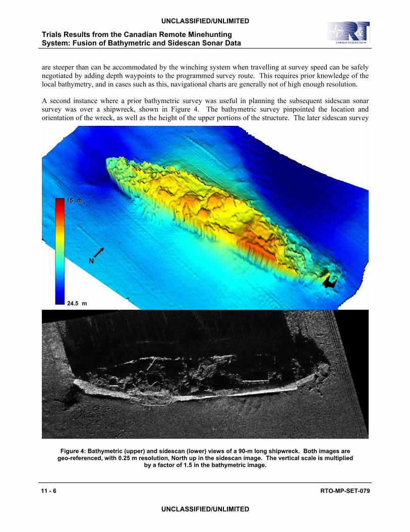
A second instance where a prior bathymetric survey was useful in planning the subsequent sidescan sonar survey was over a shipwreck, shown in Figure 4. The bathymetric survey pinpointed the location and orientation of the wreck, as well as the height of the upper portions of the structure. The later sidescan survey
Figure 4: Bathymetric (upper) and sidescan (lower) views of a 90-m long shipwreck. Both images are geo-referenced, with 0.25 m resolution, North up in the sidescan image. The vertical scale is multiplied
by a factor of 1.5 in the bathymetric image.
11 - 6 RTO-MP-SET-079
UNCLASSIFIED/UNLIMITED
UNCLASSIFIED/UNLIMITED
Trials Results from the Canadian Remote Minehunting System: Fusion of Bathymetric and Sidescan Sonar Data
route was positioned to optimize swath coverage centred on the wreck, with minimal line lengths, and towfish altitude that allowed the elevated deck and superstructure portions to be imaged. Figure 4 illustrates two views of the wreck as seen by the two sonars.
In this role, the bathymetric sonar was immediately successful during the trial. Data products from the surveys were made available for planning purposes on site. For larger scale route planning, the Reson system in fact provides real-time compilation and display of a coarser resolution bathymetric chart while under way. The commercial software which has been used for cleaning and post-processing the bathymetry data, CARIS HIPS, also allows extraction of profiles such as that shown in Figure 3.
3.2 Initial Minelike Object Survey As mentioned, until recently bathymetric sonars were deemed not to have the necessary resolution to detect minesized objects on the seabed. During the trial, a field of minelike targets (cylinder, Rockan, Manta, sphere and mid-water moored target) were deployed and surveyed with both bathymetric and sidescan sonars.
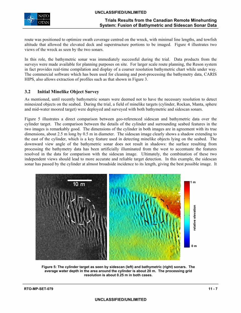
Figure 5 illustrates a direct comparison between geo-referenced sidescan and bathymetric data over the cylinder target. The comparison between the details of the cylinder and surrounding seabed features in the two images is remarkably good. The dimensions of the cylinder in both images are in agreement with its true dimensions, about 2.5 m long by 0.5 m in diameter. The sidescan image clearly shows a shadow extending to the east of the cylinder, which is a key feature used in detecting minelike objects lying on the seabed. The downward view angle of the bathymetric sonar does not result in shadows: the surface resulting from processing the bathymetry data has been artificially illuminated from the west to accentuate the features resolved in the data for comparison with the sidescan image. Ultimately, the combination of these two independent views should lead to more accurate and reliable target detection. In this example, the sidescan sonar has passed by the cylinder at almost broadside incidence to its length, giving the best possible image. It
1 m
0 m
rela
tive
elev
atio
n
Figure 5: The cylinder target as seen by sidescan (left) and bathymetric (right) sonars. The average water depth in the area around the cylinder is about 20 m. The processing grid
resolution is about 0.25 m in both cases.
RTO-MP-SET-079 11 - 7
UNCLASSIFIED/UNLIMITED
UNCLASSIFIED/UNLIMITED
Trials Results from the Canadian Remote Minehunting System: Fusion of Bathymetric and Sidescan Sonar Data
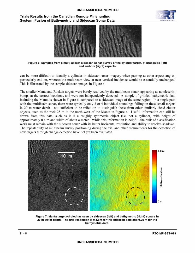
Figure 6: Samples from a multi-aspect sidescan sonar survey of the cylinder target, at broadside (left) and end-fire (right) aspects.
can be more difficult to identify a cylinder in sidescan sonar imagery when passing at other aspect angles, particularly end-on, whereas the multibeam view at near-vertical incidence would be essentially unchanged. This is illustrated by the sample sidescan images in Figure 6.
The smaller Manta and Rockan targets were barely resolved by the multibeam sonar, appearing as nondescript bumps at the correct locations, and were not independently detected. A sample of gridded bathymetric data including the Manta is shown in Figure 6, compared to a sidescan image of the same region. In a single pass with the multibeam sonar, there were typically only 3 or 4 individual soundings falling on these small targets in 20 m water depth - not sufficient to be relied on to distinguish these from other similarly sized clutter objects, such as the rock 25 m to the north-west of the Manta in Figure 6. Useful information can still be drawn from this data, such as it is a roughly symmetric object (i.e. not a cylinder) with height of approximately 0.4 m and width of about a meter. While this information is helpful, the bulk of classification work must remain with the sidescan sonar with its better horizontal resolution and ability to resolve shadows. The repeatability of multibeam survey positioning during the trial and other requirements for the detection of new targets through change detection have not yet been evaluated.
0.8 m
0 m
rela
tive
elev
atio
n
Figure 7: Manta target (circled) as seen by sidescan (left) and bathymetric (right) sonars in 20 m water depth. The grid resolution is 0.12 m for the sidescan data and 0.25 m for the
bathymetric data.
11 - 8 RTO-MP-SET-079
UNCLASSIFIED/UNLIMITED
UNCLASSIFIED/UNLIMITED
Trials Results from the Canadian Remote Minehunting System: Fusion of Bathymetric and Sidescan Sonar Data
2.3 m
0 m
-0.7 m
Nor
thw
ard
erro
r
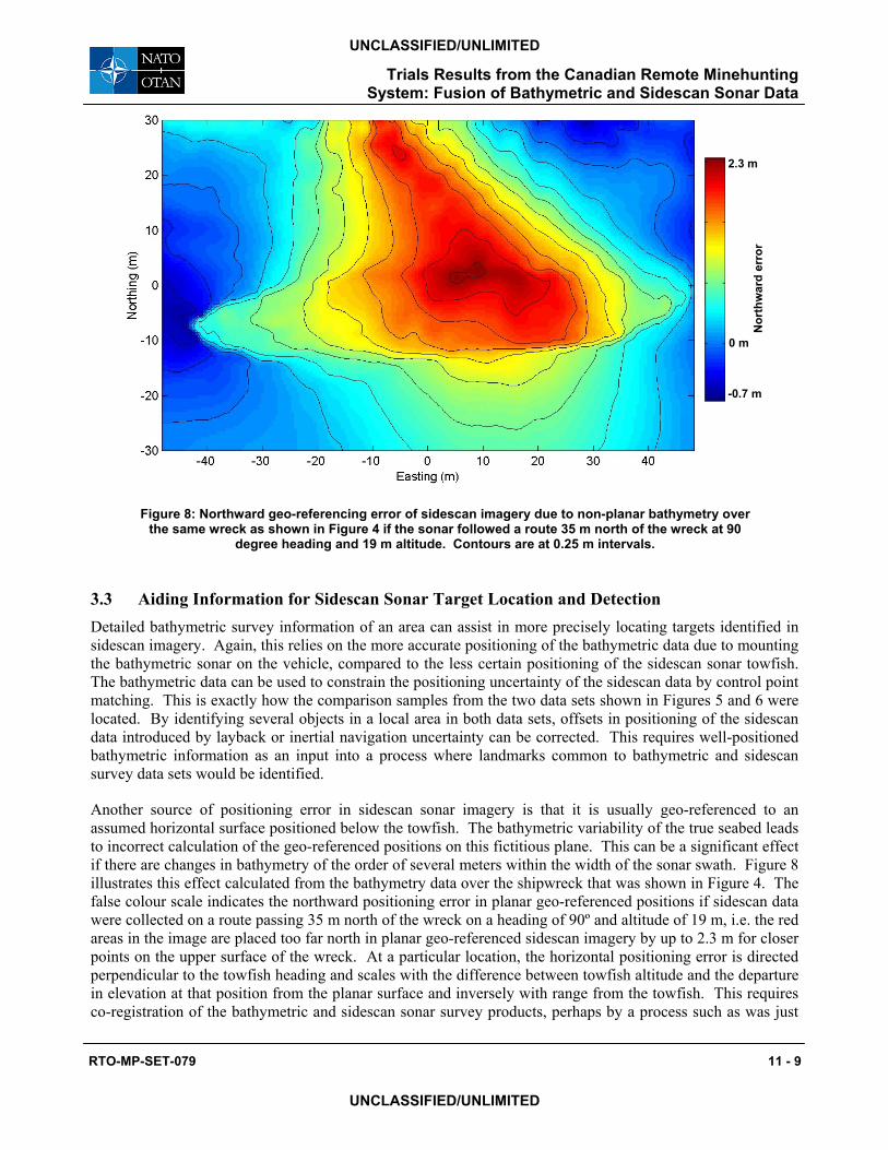
Figure 8: Northward geo-referencing error of sidescan imagery due to non-planar bathymetry over the same wreck as shown in Figure 4 if the sonar followed a route 35 m north of the wreck at 90
degree heading and 19 m altitude. Contours are at 0.25 m intervals.
3.3 Aiding Information for Sidescan Sonar Target Location and Detection Detailed bathymetric survey information of an area can assist in more precisely locating targets identified in sidescan imagery. Again, this relies on the more accurate positioning of the bathymetric data due to mounting the bathymetric sonar on the vehicle, compared to the less certain positioning of the sidescan sonar towfish. The bathymetric data can be used to constrain the positioning uncertainty of the sidescan data by control point matching. This is exactly how the comparison samples from the two data sets shown in Figures 5 and 6 were located. By identifying several objects in a local area in both data sets, offsets in positioning of the sidescan data introduced by layback or inertial navigation uncertainty can be corrected. This requires well-positioned bathymetric information as an input into a process where landmarks common to bathymetric and sidescan survey data sets would be identified.
Another source of positioning error in sidescan sonar imagery is that it is usually geo-referenced to an assumed horizontal surface positioned below the towfish. The bathymetric variability of the true seabed leads to incorrect calculation of the geo-referenced positions on this fictitious plane. This can be a significant effect if there are changes in bathymetry of the order of several meters within the width of the sonar swath. Figure 8 illustrates this effect calculated from the bathymetry data over the shipwreck that was shown in Figure 4. The false colour scale indicates the northward positioning error in planar geo-referenced positions if sidescan data were collected on a route passing 35 m north of the wreck on a heading of 90º and altitude of 19 m, i.e. the red areas in the image are placed too far north in planar geo-referenced sidescan imagery by up to 2.3 m for closer points on the upper surface of the wreck. At a particular location, the horizontal positioning error is directed perpendicular to the towfish heading and scales with the difference between towfish altitude and the departure in elevation at that position from the planar surface and inversely with range from the towfish. This requires co-registration of the bathymetric and sidescan sonar survey products, perhaps by a process such as was just
RTO-MP-SET-079 11 - 9
UNCLASSIFIED/UNLIMITED
UNCLASSIFIED/UNLIMITED
Trials Results from the Canadian Remote Minehunting System: Fusion of Bathymetric and Sidescan Sonar Data
described. Operationally, only isolated positions selected by an operator from the sonar display console (potential targets) require accurate positioning, so the computational demands would be quite light, given a suitable set of bathymetric data to work from.
The length and shape of shadows cast by targets in sidescan sonar data are key detection features. In the presence of bed slope or local small scale variation in bathymetry, the shadow is distorted. This can be accounted for when caused by seabed features which are visible in the sidescan imagery, such as the ripples surrounding the cylinder target in Figures 5 and 6. Longer length scale seabed slopes are not evident in sidescan images and at low grazing angles, a small slope can have a large effect on shadow length. High resolution bathymetric data provides target height information determined more directly than by inferring from shadow length. Coarse resolution bathymetric data may not resolve the target itself, but can be used to correct for shadow distortion by a slope.
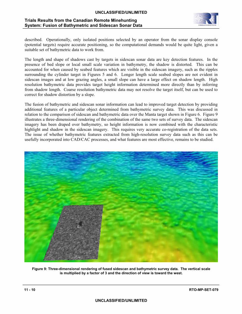
The fusion of bathymetric and sidescan sonar information can lead to improved target detection by providing additional features of a particular object determined from bathymetric survey data. This was discussed in relation to the comparison of sidescan and bathymetric data over the Manta target shown in Figure 6. Figure 9 illustrates a three-dimensional rendering of the combination of the same two sets of survey data. The sidescan imagery has been draped over bathymetry, so height information is now combined with the characteristic highlight and shadow in the sidescan imagery. This requires very accurate co-registration of the data sets. The issue of whether bathymetric features extracted from high-resolution survey data such as this can be usefully incorporated into CAD/CAC processes, and what features are most effective, remains to be studied.
Figure 9: Three-dimensional rendering of fused sidescan and bathymetric survey data. The vertical scale is multiplied by a factor of 3 and the direction of view is toward the west.
11 - 10 RTO-MP-SET-079
UNCLASSIFIED/UNLIMITED
UNCLASSIFIED/UNLIMITED
Trials Results from the Canadian Remote Minehunting System: Fusion of Bathymetric and Sidescan Sonar Data

3.4 Obstacle or Seabed Avoidance Ideally, an obstacle avoidance sonar supplies real-time information to the operators in order to avoid hazards as quickly as required. The location of the bathymetric sonar on the vehicle gives some advance warning for the following towfish, but likely not in sufficient time should a mid-water obstacle be encountered at survey speed. During the trial, real-time bathymetric profiles were available to the operator of the Reson system, but not directly to the vehicle operator.
The ability of the bathymetric sonar to resolve the seabed is not in question, however smaller mid-water targets provide more of a challenge. Figure 10 shows bathymetric measurements over a moored roughly spherical target 0.5 m in diameter, 3.5 m above the seabed. In this case, rather than processed data, the figure shows the individual soundings, such as would be displayed as profiles in real-time to the Reson operator. The vehicle heading was north at this time, so from this viewpoint, the rows of points apparent in the figure are consecutive pings on individual beams (profiles are orthogonal), with rows farther apart with increasing distance eastward from nadir. Several points fall on the target, between about 17.0 and 17.7 m depth. The shadow can be seen as a gap in the points on the seabed near the east axis. Another gap directly below the sphere is the shadow of the anchor (a concrete block), which is not itself clearly visible from this viewpoint.
Figure 10: Bathymetric soundings on a moored sphere target at 17.5 m depth in 21 m of water. The horizontal scale covers 20 m West-East by 15 m South-North, and the vertical scale is multiplied
by a factor of 3.
RTO-MP-SET-079 11 - 11
UNCLASSIFIED/UNLIMITED
UNCLASSIFIED/UNLIMITED
Trials Results from the Canadian Remote Minehunting System: Fusion of Bathymetric and Sidescan Sonar Data

information can be made useful in real-time is another issue. The operator could easily miss a few individual points on the scrolling display of sounding profiles. Many of the standard automated data cleaning tools would reject the soundings falling on the target as outliers. The Reson processor mounted on the RMS vehicle has been upgraded for volumetric imaging, however this capability has not been tested over the radio link.
4.0 SUMMARY
The installation of the bathymetric sonar on the Dorado vehicle has resulted in higher quality survey data than some previous trials where the sonar was deployed over-the-side of small and larger vessels. Results from those earlier trials were complicated by excess vessel motions, artefacts from non-rigidity in transducer mounting, and inability to precisely follow survey lines. The bathymetric surveys performed as part of the trial in Brest Harbour produced high-quality chart data which was immediately useful in route planning of subsequent sidescan sonar surveys. In 20 m water depth, the multibeam sonar was able to resolve size and shape information of the larger minelike targets, including a mid-water moored sphere.
Four concepts of operation for multibeam sonar use in minehunting were outlined. The examples from the surveys shown here demonstrate a basic capability in each of these areas, though significant effort would be required for implementation of some of these in an operational system, particularly for real-time applications. Initial reconnaissance for route planning, the first concept that was listed, shows the best potential for immediate integration into RMS operations, and in fact will be a part of upcoming trials in 2004. The bathymetric data is cleaned and post-processed, requiring at most 1 to 2 hours, resulting in field sheets which can be made available to a planner nearly immediately. This capability exists currently, as well as the ability to export gridded data and depth profiles along routes. With some modifications to the existing RMS route planning software, these could be imported for more rigorous incorporation into the planning process. The second concept, an initial minelike object survey role, appears to be feasible, as some features of all the deployed targets were resolved, including the smaller Manta and Rockan, though not independently of traditional sidescan survey imagery. The repeat navigational and positioning accuracies attained during the trial and required for the task of change detection remain to be assessed.
The last two concepts provide the greatest challenges for future implementation. The fusion of the two types of survey data undoubtedly provides additional information helpful for target detection, but the details of how and which bathymetric features can be incorporated into CAD/CAC processes remains as a large question. In order to be effective as an obstacle avoidance sonar, some level of real-time integration of the bathymetric information into the various RMS data handling processes is necessary. The results of the survey of the moored sphere target, for example, demonstrate rudimentary capability of the system, though the currently available real-time data products supplied by the sonar processor are not useful to the vehicle operators. A primary concern for future implementation will be development and testing of methods for efficient and appropriate automated cleaning and decimation of the raw bathymetry data.
11 - 12 RTO-MP-SET-079
UNCLASSIFIED/UNLIMITED
UNCLASSIFIED/UNLIMITED
Trials Results from the Canadian Remote Minehunting System: Fusion of Bathymetric and Sidescan Sonar Data
This demonstrates that the bathymetric sonar is capable of resolving a small mid-water target. Whether this
RTO-MP-SET-079 11 - 13
ACKNOWLEDGEMENTS
The authors wish to thank Benoit Zerr of GESMA and Philippe Waquet of DCN.
REFERENCES
[1] Hopkin, D.A. and J. Turner, The Remote Minehunting System Technology Demonstration Project, Underwater Defence Technology Conference, Korea, October 2002.
[2] Hopkin, D.A. Remote Minehunting Development in Canada, NATO Naval Group 3 Symposium on Unmanned Systems for Mine Countermeasures and Harbour Defence, Oostende, Belgium, October 2003.
[3] Hopkin, D.A., G.D. Watt and M.L. Seto, The Development of a Semi-Submersible Vehicle for use in Minehunting Applications, Unmanned Vehicles for Aerial, Ground and Naval Military Operations, NATO/RTO Symposium, Ankara, Turkey, October 2000.
[4] Franklin, S., and O. Beslin, CAD/CAC in the Remote Minehunting System Technology Demonstrator, CAD/CAC 2001 Conference, Halifax, Canada, November 2001.
[5] Trevorrow, M.V., A.M. Crawford and D.A. Hopkin, Integration and field trials of a High-Resolution Multibeam Sonar on the Remote Minehunting Vehicle Dorado, DRDC Atlantic Technical Memorandum TM 2003-233, December 2003.
[6] Brissette, M., The Application of Multibeam Sonars in Route Survey, MEng thesis, Department of Geodesy and Geomatics Engineering, Ocean Mapping Group, University of New Brunswick, St John, New Brunswick, Canada, 1997.
[7] Brissette, M., J. Hughes Clark, J. Bradford and B. McGowan, Detecting Small Seabed Targets Using a High Frequency Multibeam Echosounder: Geometric Models and Test Results, MTS IEEE Oceans '97 Conference, Halifax, Canada, October 1997.
UNCLASSIFIED/UNLIMITED
UNCLASSIFIED/UNLIMITED
Trials Results from the Canadian Remote Minehunting System: Fusion of Bathymetric and Sidescan Sonar Data

Trials Results from the Canadian Remote Minehunting System: Fusion of Bathymetric and Sidescan Sonar Data
11 - 14 RTO-MP-SET-079
UNCLASSIFIED/UNLIMITED
UNCLASSIFIED/UNLIMITED