integration and field trials of a high-resolution multi ... · multi-beam sonar on the remote...
TRANSCRIPT

Defence R&D Canada
DEFENCE DÉFENSE&
Integration and Field Trials of a High-Resolution
Multi-beam Sonar on the Remote Minehunting
Vehicle Dorado
Mark V. Trevorrow
Anna M. Crawford
David A. Hopkin
Technical Memorandum
DRDC Atlantic TM 2003-233
December 2003
Copy No.________
Defence Research andDevelopment Canada
Recherche et développementpour la défense Canada

This page intentionally left blank.

Copy No:
Integration and Field Trials of a High-Resolution Multi-beam Sonar on the Remote Minehunting Vehicle Dorado
Mark V. Trevorrow Anna M. Crawford David A. Hopkin
Defence R&D Canada – Atlantic Technical Memorandum DRDC Atlantic TM 2003-233 December 2003


Abstract
In early 2003, a Reson 8125 high-resolution, multi-beam bathymetric sonar system was installed on the DRDC Atlantic remote minehunting vehicle. The Dorado vehicle, a component of the Remote Minehunting System (RMS), is a semi-submersible, remotely controlled drone designed to tow an actively stabilized sidescan sonar towfish. The multi-beam sonar processor was integrated with the on-board data telemetry system, taking advantage of existing vehicle position and attitude sensors. The RMS and multi-beam sonar were then tested during a field trial near Brest, France in May and June, 2003, as part of a larger collaborative minehunting demonstration. The multi-beam sonar was successfully used to chart the bathymetry of the approaches to Brest Harbour, and for high-resolution surveys of a shipwreck, and a practice minefield. Processed results of these surveys are presented demonstrating basic capability of the system for mine detection, obstacle avoidance and as a mission planning tool. The integration of high-resolution bathymetric information has the potential to improve minehunting operation in areas such as survey route planning and sidescan image slope correction.
Résumé
Un système sonar bathymétrique multifaisceau à haute résolution Reson 8125 a été installé sur le véhicule télécommandé de déminage (Dorado) de RDDC Atlantique au début de l’année 2003. Le Dorado, qui fait partie du système télécommandé de déminage (RMS), est un véhicule-robot semi-submersible télécommandé conçu pour remorquer un sonar à balayage latéral à stabilisation active. Le processeur du sonar multifaisceau a été intégré au système embarqué de télémesure, et il peut bénéficier des capteurs de position et d’orientation déjà présents sur le véhicule. Le système RMS ainsi que le sonar multifaisceau ont été testés en mer près de Brest (France), en mai et juin 2003, dans le cadre d’une importante démonstration concertée de déminage. Le sonar multifaisceau a été utilisé avec succès pour produire des cartes bathymétriques des abords du port de Brest et pour effectuer des levés haute résolution d’une épave et d’un champ de mines d’entraînement. Les données traitées des levés sont présentées dans le document. Elles permettent de démontrer les capacités de base du système pour la détection de mines, l’évitement d’obstacles et la planification de missions. L’intégration de données bathymétriques haute résolution devrait améliorer certains aspects des opérations de déminage, comme la planification d’itinéraire de levé et la correction de pente des images obtenues par balayage latéral.
DRDC Atlantic TM 2003-233 i

Executive summary
Introduction
Unmanned semi-submersible vehicles equipped with both multi-beam and sidescan sonars represent a valuable new tool for minehunting and route survey applications. These offer greater speed, stability, and survey efficiency than small surface vessels, and when compared to autonomous underwater vehicles offer the advantages of DGPS positioning, real-time control and data telemetry, and greater range, speed, and payload carrying capabilities. A Reson Inc. model 8125 multi-beam sonar was installed on the Dorado remote minehunting vehicle and evaluated during a field trial in Brest, France in May and June, 2003.
Principal Results
The details of the multi-beam sonar integration into the Dorado on-board systems and data telemetry are presented. High-resolution bathymetric charts covering the approaches to Brest Harbour, a shipwreck, and a practice minefield were produced. Some larger mine-like targets were detectable in the measured bathymetry.
Significance of the Results
This trial constitutes one of the first evaluations of the combination of high-resolution bathymetric and sidescan sonars on a semi-submersible vehicle. The results demonstrate the potential for an emerging capability in fusion of bathymetric and sidescan sonar data.
Future Plans
Further field trials of the Dorado with coincident bathymetric and sidescan sonars should be conducted in order to better quantify the abilities and limitations of the overall system. In particular, the concept of change detection should be investigated. Software developments to better integrate bathymetric and sidescan sonar data for route planning and real-time CAD/CAC should be pursued.
Trevorrow, M., Crawford, A., & Hopkin, D. 2003. Integration and field trials of a high-resolution multi-beam sonar on the remote minehunting vehicle Dorado. TM 2003-233 DRDC Atlantic.
ii DRDC Atlantic TM 2003-233

Sommaire
Introduction
Les véhicules semi-submersibles équipés à la fois d’un sonar multifaisceau et d’un sonar à balayage latéral sont un outil nouveau et précieux pour les activités de déminage et de levé de tracés. Ils sont plus rapides, plus stables et plus efficaces pour faire des levés que les petits navires de surface. En outre, comparativement aux véhicules sous-marins autonomes, ils offrent le positionnement DGPS, la commande en temps réel et la télémesure, en plus d’avoir des capacités supérieures sur les plans de la portée, de la vitesse et du transport de charge utile. Un sonar multifaisceau Reson 8125, installé sur le véhicule télécommandé de déminage Dorado, a été testé en mer près de Brest (France), pendant les mois de mai et juin 2003.
Principaux résultats
On retrouve dans le présent document les détails concernant l’intégration du sonar multifaisceau aux systèmes embarqués du Dorado, dont le système de télémesure. Des cartes bathymétriques à haute résolution des abords du port de Brest, d’une épave et d’un champ de mines d’entraînement ont été produites. Certaines cibles plus grandes, semblables à des mines, pouvaient être détectées sur les cartes bathymétriques établies.
Importance des résultats
Ces essais sont en fait une des premières évaluations de la combinaison d’un sonar à balayage latéral et d’un sonar bathymétrique haute résolution sur un véhicule semi-submersible. Les résultats obtenus permettent de démontrer la possibilité d’une nouvelle capacité résultant de la fusion des données obtenues au moyen de ces systèmes sonar.
Plans pour l'avenir
Il faudrait effectuer d’autres essais du Dorado, doté d’un sonar à balayage latéral et d’un sonar bathymétrique, afin de mieux évaluer quantitativement les capacités et les limites du système dans son ensemble. Plus particulièrement, il faudrait examiner le principe de détection de variation. On devrait également travailler au développement de logiciels afin de mieux intégrer les données des sonars à balayage latéral et bathymétrique pour la planification d’itinéraire et la détection et classification assistées par ordinateur (CAD/CAC) en temps réel.
Trevorrow, M., Crawford, A., & Hopkin, D. 2003. Integration and field trials of a high-resolution multi-beam sonar on the remote minehunting vehicle Dorado (Intégration et essais en mer d’un sonar multifaisceau haute résolution à bord du véhicule télécommandé de déminage Dorado). TM 2003-233 RDDC Atlantique.
DRDC Atlantic TM 2003-233 iii
Acknowledgements
This integration work was supported in a collaboration between the Canadian Dept. of National Defence (through DRDC Atlantic) and DCN International of France. The authors are grateful for the support of Phillipe Waquet of DNCI during the trials in Brest, France. Additional collaboration with Drs. Beniot Zerr and Joel LeHars of Groupe d'études sous-marines de l'Atlantique (GESMA) in Brest France was greatly appreciated. Valuable technical assistance in sonar integration and field trails was provided by Landy Shupe, David Eddy, Rod Penner, Tristan Crees, and Al West all of International Submarine Engineering Research Ltd., Port Coquitlam, BC. Sonar and vehicle testing during the May-June field trials in France were greatly assisted by Terry Miller, Richard Pedersen, and Mark Rowsome, all of DRDC Atlantic.
iv DRDC Atlantic TM 2003-233

Table of contents
Abstract........................................................................................................................................ i
Executive summary .................................................................................................................... ii
Sommaire................................................................................................................................... iii
Acknowledgements ................................................................................................................... iv
Table of contents ........................................................................................................................ v
List of figures ............................................................................................................................ vi
1. Introduction ................................................................................................................... 1
2. Mounting and Setup of Reson 8125 on Dorado ............................................................ 4
3. Summary of Field Trial Results..................................................................................... 8 3.1 Bathymetric survey of Le Goulet ..................................................................... 8 3.2 Wreck of the Gobetas ....................................................................................... 9 3.3 Deployed Mine-like Targets........................................................................... 10
4. Discussion of Operations and Results ......................................................................... 13
5. Summary and Recommendations ................................................................................ 14
Appendix 1: Reson Seabat System Specifications ................................................................... 15
Appendix 2: Sensor Mounting Offsets and Sign Conventions ................................................. 16
DRDC Atlantic Document Distribution List ............................................................................ 18
DRDC Atlantic TM 2003-233 v

List of figures
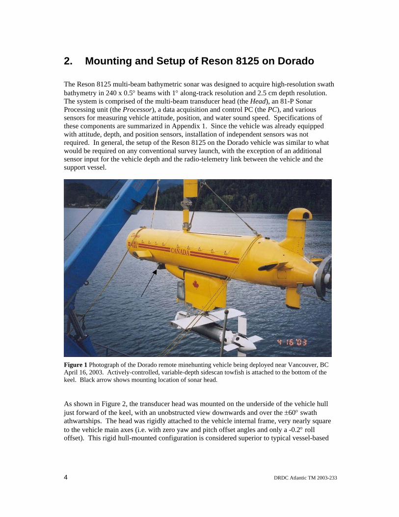
Figure 1 Photograph of the Dorado remote minehunting vehicle being deployed near Vancouver, BC April 16, 2003. Actively-controlled, variable-depth sidescan towfish is attached to the bottom of the keel. Black arrow shows mounting location of sonar head. 4
Figure 2 Photograph of the Reson 8125 transducer mounted on the underside of the Dorado vehicle, just forward of the towfish winch assembly in the keel. The black cylinder projecting forward is the transmitter, while the receive array lies behind the black rectangular plate just aft of the projector............................................................................. 5
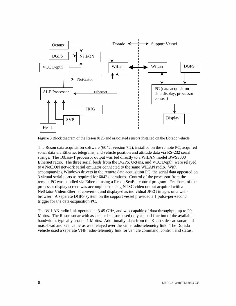
Figure 3 Block diagram of the Reson 8125 and associated sensors installed on the Dorado vehicle. ................................................................................................................................ 6
Figure 4 Partial coverage bathymetric map of Le Goulet, the entrance to Brest Harbour (artificially sun-illuminated and depths colour coded). The grid lines are at 1 km intervals (UTM coordinates, zone 30) and the depth colour scale is shown in Figure 5. ... 8
Figure 5 Depth profile along the route shown by the black line in Figure 4, plotted against distance along the route from West to East (both axes in meters). The arrows indicate steep slopes where the route crosses the boundary of the channel...................................... 8
Figure 6 Comparison of sidescan and bathymetric sonar views of a shipwreck in Brest Harbour. Both are processed (gridded) to approximately 25 cm resolution. Bathymetric colour scale ranges from deep blue at 24 m to red at 15 m depth. ...................................... 9
Figure 7 Bathymetric soundings in the vicinity of a moored sphere target at 17.5 m depth. The horizontal scale covers 20 m West-East by 15 m South-North, and the vertical scale has been exaggerated by a factor of 3. .............................................................................. 10
Figure 8 The cylinder target as seen by sidescan sonar (left) and bathymetric sonar (right). The average water depth in the area around the cylinder is about 20 m. The grid resolution is about 0.25 m. ................................................................................................ 11
Figure 9 Manta target as seen by sidescan sonar (left) and bathymetric sonar (right). The average water depth in the area is 20 m. The grid resolution is 0.12 m for the sidescan data and 0.25 m for the bathymetry data. ......................................................................... 12
vi DRDC Atlantic TM 2003-233

This page intentionally left blank.
DRDC Atlantic TM 2003-233 vii

This page intentionally left blank.
viii DRDC Atlantic TM 2003-233

1. Introduction
Unmanned semi-submersible vehicles represent a valuable new platform for the conduct of minehunting and hydrographic surveys. Typical semi-submersible vehicles are diesel-engine powered, operating at a depth of several meters with a surface-piercing mast to provide air and radio communication. In littoral zones relevant to minehunting, such vehicles are generally superior to both surface ships and autonomous underwater vehicles (AUVs) in survey efficiency and sonar data quality. A remotely operated vehicle removes human operators from areas of risk during minehunting operations while at the same time allowing real-time data monitoring and control. Specifically, when compared to surface ships, a semi-submersible platform has advantages in:
• the ability to operate routinely at speeds of 8 to 10 knots, a higher speed than generally possible for a small to medium sized hydrographic vessel,
• better attitudinal (pitch-roll-yaw) stability in waves and immunity from wind effects, producing better quality bathymetric data and less tow-induced motion of the variable depth towfish (VDT).
• better ability to follow precise survey lines with minimal end-of-line manoeuvring.
• simpler and safer deployment of the VDT.
When compared to AUVs, the semi-submersible concept is superior in:
• provision of real-time data radio-telemetry and ability to adapt surveys on-the-fly,
• precise DGPS positioning, which translates into improved target positioning from both multi-beam and sidescan sonar systems.
• greater range-speed capability, resulting in greater coverage area and coverage rate.
• greater payload carrying ability.
When coupled with new high-resolution multi-beam sonar technologies, accurate and efficient seabed surveys with sufficient resolution for minehunting and route survey applications are feasible.
Although the primary focus of the Remote Minehunting System (RMS) development has been the provision of high-quality sidescan sonar imagery, these advantages make the vehicle an ideal platform for multi-beam bathymetric sonar operations. There are four primary concepts of operation for a multi-beam sonar in the context of minehunting surveys:
1. as part of an initial reconnaissance to provide detailed bathymetric information that can assist route and altitude planning for later sidescan sonar surveys by identifying potentially dangerous slopes, shipwrecks, or mid-water objects.
DRDC Atlantic TM 2003-233 1
2. to provide an initial survey for mine-like targets that can be confirmed by later sidescan surveys. The hull-mounting of the bathymetric sonar affords more precise positioning of the resulting data products than the towfish-mounted sidescan sonar, so that the multi-beam sonar is also especially useful for detecting small bathymetric changes relative to previous surveys.
3. to provide independent information that when fused with sidescan sonar data, can be used to enhance target location ability (for example, correction for seabed slope or improvement of towfish location in the absence of reliable towfish navigation sensors), and potentially to add features for Computer Aided Detection and Classification (CAD/CAC).
4. to provide real-time obstacle and seabed avoidance warnings for the VDT.
A key idea is that the bathymetric sonar provides information complementary to that derived from the sidescan sonar. The sidescan sonar provides high spatial resolution, but has positioning uncertainty resulting from tow cable/VDT dynamics or inaccuracy in the towfish inertial navigation system. Conversely, the hull-mounted multi-beam sonar has high positioning accuracy but somewhat lower horizontal resolution. Also, the sidescan sonar provides a low-grazing-angle view that may be sensitive to aspect, whereas the multi-beam sonar provides a near-vertical-incidence view. Together, information from the two sonars can be utilized to enhance both efficiency of operation and target location performance. Once equipped with a bathymetric sonar, the vehicle is also ideal for normal bathymetric surveys, such as those required for routine Naval route survey operations, pipeline or cable laying, or conventional civilian hydrographic surveys.
This report focuses on the integration of a specific multi-beam sonar, the Reson Inc. SeaBat 8125 system, into the Dorado remote minehunting vehicle. The Reson 8125 multi-beam bathymetric sonar is designed to acquire high-resolution (of order cm) bathymetry in a 240-beam swath 120° athwartships by 1° along-track. The sonar operates at 455 kHz, providing high angular resolution in a relatively small transducer package. This sonar is limited to sampling ranges less than 120 m, best suited for swath bathymetric surveys in water depths less than 60 to 80 m. The Dorado vehicle, shown in Figure 1, is a prototype semi-submersible vehicle that has been developed by the Canadian Dept. of National Defence and manufactured by International Submarine Engineering Research (ISER). The vehicle is 8.3 m long with a hull diameter of 1.17 m and weighs 6400 kg fully fuelled. A 5 m surface-piercing mast supports various radio and DGPS antennae, and provides the air-intake for the 260 kW diesel engine. To reduce torque effects, the vehicle is propelled with dual counter-rotating propellers. A 1.5 m deep keel houses a cable winching system for the VDT, which supports a Klein 5500 sidescan sonar. Towed sidescan operations in water depths up to 200 m are feasible. The Dorado typically operates at speeds of 8 to 10 knots at a depth of 3.3 m, with maximum range at this speed of 120 nautical miles (220 km). The vehicle maximum speed is near 16 knots.
2 DRDC Atlantic TM 2003-233
The work to integrate and field test the Reson 8125 on the Dorado was initiated in the spring of 2003. The primary sonar integration work was conducted at the ISER facility near Vancouver, BC, April 10-17, 2003. The Vancouver workup trial included three days of sea-trials in Burrard Inlet. The primary field testing of the Reson-Dorado combination was accomplished as part of a scientific demonstration program conducted near Brest, France from May 26 to June 20, 2003. This trial included surveys over a string of four practice mines and a shipwreck, and a lower-resolution survey of the main entrance into Brest Harbour.
The intent of this report is two-fold: firstly to document details of the physical integration and software setup of the Reson sonar on the Dorado, and secondly to summarize and evaluate capabilities of the sonar-vehicle combination as demonstrated during the Brest field trials.
DRDC Atlantic TM 2003-233 3
2. Mounting and Setup of Reson 8125 on Dorado
The Reson 8125 multi-beam bathymetric sonar was designed to acquire high-resolution swath bathymetry in 240 x 0.5° beams with 1° along-track resolution and 2.5 cm depth resolution. The system is comprised of the multi-beam transducer head (the Head), an 81-P Sonar Processing unit (the Processor), a data acquisition and control PC (the PC), and various sensors for measuring vehicle attitude, position, and water sound speed. Specifications of these components are summarized in Appendix 1. Since the vehicle was already equipped with attitude, depth, and position sensors, installation of independent sensors was not required. In general, the setup of the Reson 8125 on the Dorado vehicle was similar to what would be required on any conventional survey launch, with the exception of an additional sensor input for the vehicle depth and the radio-telemetry link between the vehicle and the support vessel.
Figure 1 Photograph of the Dorado remote minehunting vehicle being deployed near Vancouver, BC April 16, 2003. Actively-controlled, variable-depth sidescan towfish is attached to the bottom of the keel. Black arrow shows mounting location of sonar head.
As shown in Figure 2, the transducer head was mounted on the underside of the vehicle hull just forward of the keel, with an unobstructed view downwards and over the ±60° swath athwartships. The head was rigidly attached to the vehicle internal frame, very nearly square to the vehicle main axes (i.e. with zero yaw and pitch offset angles and only a -0.2° roll offset). This rigid hull-mounted configuration is considered superior to typical vessel-based
4 DRDC Atlantic TM 2003-233

deployment using an over-the-side pole, as it avoids problems with pole wobble, non-repeatability in pole placement, and allows greater survey speed. The rigid mounting configuration allows for precise and repeatable seabed target positioning. The sound velocity probe (SVP) was mounted close to the head, just inside a free-flooding cowling aft of the head. Underwater cables from the head and sound velocity probe were led through the hull into the electronics bay.
Figure 2 Photograph of the Reson 8125 transducer mounted on the underside of the Dorado vehicle, just forward of the towfish winch assembly in the keel. The black cylinder projecting forward is the transmitter, while the receive array lies behind the black rectangular plate just aft of the projector.
The Dorado electronics bay housed (among other things) the processor, vehicle position and attitude sensors, a Vehicle Control Computer (VCC), and the radio telemetry transmitter. Figure 3 shows a block diagram of the sonar and sensor interconnections. Vehicle position was acquired at 5 Hz update rate using a RACAL Landstar system, with the antenna mounted on the top of the vehicle mast. Vehicle attitude (pitch, roll, heave) and heading were measured with an iXSea Octans sensor, also updated at 5 Hz. The positions of the head, DGPS antenna, and Octans sensor with respect to the vehicle center of gravity (CoG), necessary to convert the sonar data to geo-referenced bathymetry, are summarized in Appendix 2. Measured vehicle depth, acquired with a pressure sensor mounted near the bow along the vehicle center-line, was output (serial) by the VCC with a 1 Hz update rate. Local water sound speed, necessary for sonar beam-forming by the processor, was acquired directly from the sound-velocity probe translator. Finally, an IRIG time-code generator was configured to supply a serial UT time-stamp to the processor.
DRDC Atlantic TM 2003-233 5
Support Vessel Octans
VCC
NetEON
81-P
Hea
Dorado
Figure
The Resonar dstrings.Etherneto a Neaccomp3 virtuaremoteprocessNetGatbrowsetrigger
The WMbit/s.bandwimast-hevehicle
6
DGPS
Depth
NetGator
Processor
SVP
IRI
WiLan WiLan
PC (data acquisition data display, processor
DGPS
t
d
3 Block diagram of the Res
son data acquisition softwata via Ethernet telegram The 10base-T processot radio. The three serialtEON network serial emuanying Windows driversl serial ports as required
PC was handled via Etheor display screen was acor Video/Ethernet conver. A separate DGPS systfor the data-acquisition P
iLAN radio link operated The Reson sonar with adth, typically around 1 Mad and keel cameras wa
used a separate VHF rad
Etherne
G
control)
Display
on 8125 and associated sensors installed on the Dorado vehicle.
are (6042, version 7.2), installed on the remote PC, acquired s, and vehicle position and attitude data via RS-232 serial r output was fed directly to a WiLAN model BWS3000 feeds from the DGPS, Octans, and VCC Depth, were relayed lator connected to the same WiLAN radio. With in the remote data acquisition PC, the serial data appeared on for 6042 operations. Control of the processor from the rnet using a Reson SeaBat control program. Feedback of the
complished using NTSC video output acquired with a rter, and displayed as individual JPEG images on a web-em on the support vessel provided a 1 pulse-per-second C.
at 3.45 GHz, and was capable of data throughput up to 20 ssociated sensors used only a small fraction of the available bit/s. Additionally, data from the Klein sidescan sonar and
s relayed over the same radio-telemetry link. The Dorado io-telemetry link for vehicle command, control, and status.
DRDC Atlantic TM 2003-233
The vehicle elevation was determined from a combination of the vehicle depth and heave sensors. Due to contamination from ULF electronic noise, long-period vehicle height/depth variations could not be measured using the heave sensor (note that Octans heave output, like most sensors of this type, was generated from double-integration of the corrected vertical acceleration, which is sensitive to near-DC electrical noise contamination). During these trials it was found that a high-pass filter time-constant of 40 s was appropriate to remove noise contamination in the vehicle heave. Conversely, pressure measurements are sensitive to both mean vehicle depth and unwanted fluctuations due to sea surface waves. Low-pass filtering (smoothing over a 10 s window) was necessary to remove wave fluctuations. The true vehicle height relative to the mean sea surface was then the sum of these two.
The Reson-supplied data recording software, 6042, stored the bathymetry and ancillary sensor data in a proprietary binary format. However, the independent software package (CARIS HIPS/SIPS, version 5.3) that was subsequently used for data processing does not read this format directly. A solution to this was to export the data from Reson 6042 in the industry-standard XTF format, which CARIS HIPS/SIPS can read. Data processing consisted of conditioning the navigation and attitude data from the ancillary sensors by smoothing, adjusting for tidal offset if necessary, then cleaning the bathymetry data by manually removing obvious outliers. Finally, the bathymetry data were binned by horizontal position onto regular grids (vertical coordinates falling within a grid bin are averaged) at a spacing appropriate for the horizontal sample interval. The final products (known as field sheets) shown in the following section are colour-coded by depth, with blue indicating deepest and red shallowest, and have been artificially sun-illuminated to highlight features.
DRDC Atlantic TM 2003-233 7

3. Summary of Field Trial Results
Bathymetric surveys were conducted over several areas in and around the approaches to Brest Harbour. Following are samples of processed bathymetry data from these surveys.
3.1 Bathymetric survey of Le Goulet
A bathymetric survey partially covering Le Goulet, the entrance to Brest Harbour, was required to assist in planning a sidescan survey route through this area. The French requested that the bathymetric sonar ping rate be reduced to a maximum of 1 Hz while surveying this sensitive area. This results in an approximately 5 m along-track horizontal sampling interval, coarser resolution than is normally achievable in this water depth. The map shown in Figure 4 was compiled over 4 days while transiting out and back to survey areas outside the harbour. The overlaid grid is marked at 1 km intervals, Easting and Northing, in UTM coordinates (zone 30). The level of detail evident, even at this lower resolution, is far superior to most navigational charts.
Figure 4 Partial coverage bathymetric map of Le Goulet, the entrance to Brest Harbour (artificially sun-illuminated and depths colour coded). The grid lines are at 1 km intervals (UTM coordinates, zone 30) and the depth colour scale is shown in Figure 5.
Figure 5 Depth profile along the route shown by the black line in Figure 4, plotted against distance along the route from West to East (both axes in meters). The arrows indicate steep slopes where the route crosses the boundary of the channel.
8 DRDC Atlantic TM 2003-233

The bathymetry shows a deeply incised channel with side branches. The black line on the map in Figure 4 shows the course of the depth profile shown in Figure 5. This route crosses above the channel in several places and encounters the steep edge of the channel at two points indicated by the arrows. When traveling East-to-West, these slopes are greater than can be accommodated by the automated terrain-following system. With prior knowledge, these slopes can be negotiated safely by adding specific depth-change waypoints to the predetermined route plan. A prior bathymetry survey can then supply information critical to the mission planning process in cases like this. The processing software (CARIS) allows export of the profile data, as well as the gridded bathymetry results, which could be incorporated into RMS mission planning software.
3.2 Wreck of the Gobetas
Figure 6 Comparison of sidescan and bathymetric sonar views of a shipwreck in Brest Harbour. Both are processed (gridded) to approximately 25 cm resolution. Bathymetric colour scale ranges from deep blue at 24 m to red at 15 m depth.
Partly for future comparison with bathymetric measurements obtained previously by GESMA using an interferometric version of the Klein 5500 sidescan sonar, and partly due to interest, a shipwreck lying near the Harbour entrance was surveyed with both bathymetric and sidescan sonars. Figure 6 shows two views of the wreck as seen by the two sonars. Both data sets have been gridded with approximately 25 cm horizontal resolution, though the sidescan sonar
DRDC Atlantic TM 2003-233 9

has inherently finer horizontal resolution than the bathymetric sonar. The wreck is roughly 90 m long, and the bathymetric data shows the elevation of the highest points is almost 5 m above the nominally 20 m water depth of the surrounding area. Also, scour areas in the seabed up to 2 m deep near the bow (left) and starboard quarter (upper right) are visible in the multi-beam image. Comparing the two images, highlights in the sidescan sonar image correspond to near-vertical surfaces in the bathymetric data.
This survey was conducted in two steps. First, a bathymetric survey of the area was conducted to determine the depth, size, orientation, and maximum projection above the seabed of this wreck. This information was then used to plan the sidescan sonar survey, which was accomplished with tracks parallel to the long axis of the wreck at a range of roughly 30 m to either side, producing optimal sidescan imagery on the first pass. This demonstrates the value of preliminary bathymetric survey data in planning the sidescan surveys.
3.3 Deployed Mine-like Targets
sphere
shadow
Figure 7 Bathymetric soundings in the vicinity of a moored sphere target at 17.5 m depth. The horizontal scale covers 20 m West-East by 15 m South-North, and the vertical scale has been exaggerated by a factor of 3.
10 DRDC Atlantic TM 2003-233

A series of mine-like targets, including a cylinder, a Rockan, a Manta, and moored mid-water targets were deployed in an area outside the Harbour entrance. Figure 7 shows bathymetric measurements over a moored sphere target about half a meter in diameter and 3.5 m above the seabed. In this case, the figure shows the individual soundings, rather than gridded data. The vehicle heading was North at this time, so the rows of points apparent in the figure are consecutive pings on individual beams, with rows farther apart on the seabed with increasing distance Eastward from nadir. Several points fall on the body of the sphere, between about 17.0 and 17.7 m depth. The shadow of the sphere can be seen as a gap in the points on the seabed near the East axis about 3 m from the origin. Another gap directly below the sphere is the shadow behind the anchor (a concrete block), which is not itself clearly visible from this viewpoint. In this case, gridding the bathymetry data would hide the mid-water target by averaging, and many automated data cleaning tools would reject the soundings falling on the sphere as outliers.
Figure 8 shows gridded bathymetry and sidescan data (0.25 m grid resolution) covering the cylinder target lying on a rippled bed. The cylinder is about 2.5 m long and 0.5 m in diameter. The comparison between the details of the cylinder and surrounding seabed features in the two images is remarkably good. The sidescan image shows a well-resolved shadow extending to the east of the cylinder, which is a key feature used in detecting mine-like objects lying on the seabed. The downward view angle of the bathymetric sonar does not result in shadows, however the dimensions of the cylinder in that image are in rough agreement with its true dimensions. Ultimately, the combination of these two independent views should lead to more accurate and reliable target detection. In this example, the sidescan sonar has passed by the cylinder at almost broadside incidence to its length and to the ripple crests, giving the best possible image. It can be more difficult to identify the cylinder from sidescan sonar data when passing at other aspect angles, particularly end-on. The multi-beam view at near-vertical incidence would be essentially unchanged.
10 m
1 m
0 m
Figure 8 The cylinder target as seen by sidescan sonar (left) and bathymetric sonar (right). The average water depth in the area around the cylinder is about 20 m. The grid resolution is about 0.25 m.
DRDC Atlantic TM 2003-233 11
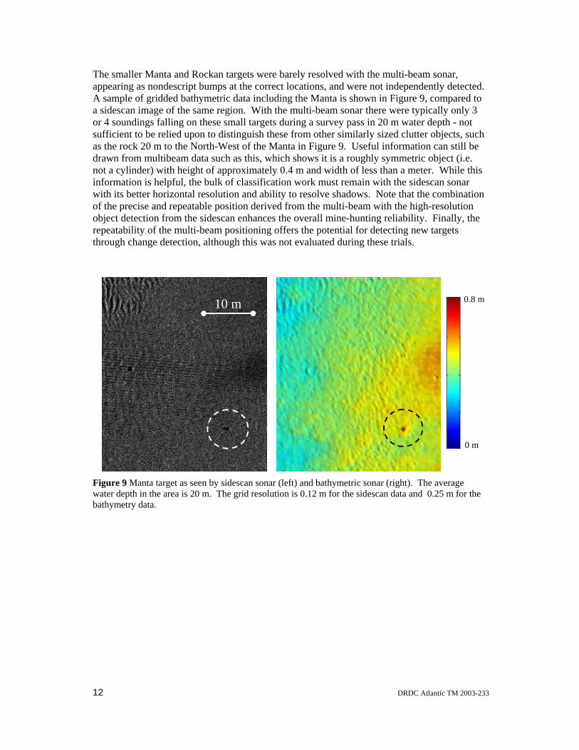
The smaller Manta and Rockan targets were barely resolved with the multi-beam sonar, appearing as nondescript bumps at the correct locations, and were not independently detected. A sample of gridded bathymetric data including the Manta is shown in Figure 9, compared to a sidescan image of the same region. With the multi-beam sonar there were typically only 3 or 4 soundings falling on these small targets during a survey pass in 20 m water depth - not sufficient to be relied upon to distinguish these from other similarly sized clutter objects, such as the rock 20 m to the North-West of the Manta in Figure 9. Useful information can still be drawn from multibeam data such as this, which shows it is a roughly symmetric object (i.e. not a cylinder) with height of approximately 0.4 m and width of less than a meter. While this information is helpful, the bulk of classification work must remain with the sidescan sonar with its better horizontal resolution and ability to resolve shadows. Note that the combination of the precise and repeatable position derived from the multi-beam with the high-resolution object detection from the sidescan enhances the overall mine-hunting reliability. Finally, the repeatability of the multi-beam positioning offers the potential for detecting new targets through change detection, although this was not evaluated during these trials.
10 m
0 m
0.8 m
Figure 9 Manta target as seen by sidescan sonar (left) and bathymetric sonar (right). The average water depth in the area is 20 m. The grid resolution is 0.12 m for the sidescan data and 0.25 m for the bathymetry data.
12 DRDC Atlantic TM 2003-233
4. Discussion of Operations and Results
While the overall operation of the multi-beam sonar on Dorado was quite reliable and produced excellent results, a few operational constraints remain to be investigated. In particular, while underway it was found that the sidescan and bathymetric sonars, both operating at 455 kHz, interfered with each other. There was significant cross-talk to the bathymetric sonar when towing the VDT close to the vehicle in shallow (20 m) water. The sidescan sonar appeared to be less affected, however it was decided during the trials to operate only one system at a time. Clearly, with increased VDT separation from the vehicle this problem would be reduced. A possible solution would be to synchronize the ping rates, however this may require non-trivial modifications to both sonar systems. Another issue that was initially identified as a potential problem were the inevitable drop-outs in the radio link between the support vessel and vehicle, due partly to directionality and nulls in the ship-based antenna response. In fact, the Reson recording software proved to be surprisingly robust to these interruptions. The limit of operating range was not tested as the ship-vehicle separation during bathymetric surveys was generally less than 1 km.
Four concepts of operation for multi-beam sonar use in minehunting were outlined in the Introduction. The examples shown here demonstrate a basic capability in each of these areas, though significant effort would be required for implementation of some of these in an operational system, particularly for real-time applications. Initial reconnaissance for route planning shows the best potential for immediate integration into RMS operations. The bathymetric data can be post-processed in the usual way, requiring at most 1 to 2 hours, resulting in field sheets which can be made available to a planner nearly immediately. This capability exists currently, as well as the ability to export gridded data and depth profiles along proposed routes. With some modifications to the existing route planning software, these could be imported for more rigorous incorporation into the planning process. Another possibility would be to acquire the software libraries for reading and writing the CARIS data files directly, eliminating a step in the transfer of the bathymetric data. The second concept, a change-detection approach relying on the positioning accuracy of the multi-beam sonar, was not tested specifically during this trial. The results suggest this is feasible, as some features of all the deployed targets were resolved, including the smaller Manta and Rockan. The repeat navigational and positioning accuracies required for this task remain to be assessed.
The last two concepts provide the greatest challenges for future implementation as these require some level of real-time integration of the bathymetric information straight from the processor into the various RMS data handling processes. The results of the survey of the moored sphere target, for example, demonstrate rudimentary capability of the system as an obstacle avoidance sonar, though most automated data cleaning procedures would reject the soundings falling on the sphere as outliers. A primary concern then is development and testing of methods for efficient and appropriate automated cleaning and decimation of the raw data. Once reduced to a manageable form, the bathymetric information can be used to correct sidescan geo-referencing for towfish positioning uncertainty or for seabed slope and elevation distortion, to resolve the ambiguity in seabed backscatter strength between slope and surface reflectivity, and to aid in identification of objects with strong directionality, such as cylinders.
DRDC Atlantic TM 2003-233 13

5. Summary and Recommendations
The data products resulting from the bathymetric surveys show that the system has performed well. In fact, the Dorado installation produced higher quality data than some previous trials where the sonar was deployed from small vessels. Results from those earlier trials were complicated by excess vessel motions, artefacts from non-rigidity in transducer mounting, and inability to precisely follow survey lines. The bathymetric survey of Le Goulet (Fig. 4) produced high-quality chart data which was useful in route planning. In 20 m water depth, the multi-beam sonar was able to detect and resolve size and shape information of the larger mine-like targets, including a mid-water moored sphere. Finally, a high-resolution sidescan sonar survey of a 90-m-long shipwreck was greatly aided, in both planning and data interpretation, by a preliminary bathymetric survey.
Some operational and technical issues remain to be addressed, specifically.
• Trial runs in deeper water are needed to determine the minimum vehicle-to-VDT separation required to reduce cross-talk between the multi-beam and sidescan sonars to an acceptable level. Additionally, the technical feasibility of synchronizing multi-beam and sidescan sonar pings should be investigated.
• An assessment should be made of the best way to import the bathymetric information now available into the RMS route-planning software. A specific question is whether that is best accomplished through intermediate files or through direct access to the bathymetric data using CARIS software libraries.
• In order to efficiently integrate the bathymetric data, potentially in real-time, into RMS operations, methods for automated conditioning and decimation of the raw data need to be developed and tested. One specific difficulty will be the need to retain soundings on mid-water objects such as moored mines, while rejecting outliers created by low signal-to-noise conditions and nuisance objects such as fish schools.
• Once the bathymetric information has been made available to the RMS operators and automated processes, effective means of utilization must be developed. This could include, for example, obstacle or seabed-slope avoidance warnings, sidescan sonar data geo-referencing corrections, and bathymetric feature extraction for CAD/CAC.
14 DRDC Atlantic TM 2003-233

Appendix 1: Reson Seabat System Specifications
Transducer Head:
acoustic: 455 kHz, 1 transmit beam at 1.0° (alongship) x 120°, 240 receive beams at 0.5° (athwartship), pulse-length selectable 30 to 270 µs, receiver sample-rate 28 kHz
physical size: 500 mm wide, 192 mm deep, 383 mm (fore-aft) length overall
connects to 81-P via multi-conductor cable (1 x coaxial for data uplink, 1 x shielded-twisted pair for downlink, 2 x 16awg for power).
weight: 24 kg (air), 11 kg equivalent in water
operating temperature: -5° to +40° Celsius
81-P Processor:
physical size: fits standard 19” rack, 17.8 cm high, 43.2 cm deep
weight: approx. 20 kg
power: 110-120 VAC, 350 W nominal
operating temperature: 0° to +35° Celsius
Sound Velocity Probe:
wet-end sensor: 51 mm (2”) dia. x 150 mm long
translator/power unit: 150mm x 102mm x 76mm, 110VAC at <50 W
output: RS-232 at 9600,N,8,1
DRDC Atlantic TM 2003-233 15

Appendix 2: Sensor Mounting Offsets and Sign Conventions
The vehicle center of gravity (CoG) is assumed to lie at the intersection between the floor and aft bulkhead of the electronics bay, at the vehicle athwartships mid-line. This is near the physical center of the vehicle, and directly beneath the mast mount. Note that depending on the vehicle ballasting and towing configuration, this position may not be exactly co-located with the true center-of-gravity, but the error is small (< 20 cm).
For multi-beam processing purposes, the vehicle coordinate system is chosen following the Reson convention, which is also in accordance with the standard vessel dynamics convention: x-axis: athwartships, positive to starboard y-axis: alongships, positive toward the bow z-axis: vertical, positive upward pitch: rotation about x-axis, positive bow up roll: rotation about y-axis, positive starboard down yaw: rotation about z-axis, positive clockwise (same as compass) heave: vertical displacement, positive upwards surge and sway are not relevant, nor measured All distances in meters and all angles are in degrees.
Note that the CARIS software coordinate system is similar in displacements except for the z-axis positive downwards (opposite z-offset and heave). Additionally, CARIS defines pitch and roll in the opposite sense (i.e. pitch is positive bow down and roll is positive starboard up). The conversion between coordinate systems is handled through the sign conventions of the XTF file format.
For both Reson and CARIS processing systems, the 8125 Transducer mounting should be set with a -0.2° roll offset, with zero pitch and yaw offsets. The Octans is mounted with zero offset angles. Table 1: Transducer and sensor offsets measured from the Dorado CoG.
Sensor X (m) Y (m) Z (m)
8125 Transducer -0.063 0.381 -0.584
Octans (attitude + gyro) 0.300 0.970 0.070
DGPS Antenna 0.0 0.0 5.74
The vehicle depth sensor is physically located near the bow on the vehicle centerline, with the pressure ports configured to measure the static (as opposed to dynamic) pressure, such that the VCC outputs the depth of the vehicle centerline, independent of vehicle speed. Output of the depth sensor is positive downwards.
Neither the sound velocity probe location nor its output are critical in the post-processing of the bathymetry data, though the processor uses it in beamforming. The probe is mounted aft and above the transducer head inside a free-flooding compartment.
16 DRDC Atlantic TM 2003-233

DRDC Atlantic Document Distribution List Document No.: DRDC ATLANTIC TM 2003-233 LIST PART 1: CONTROLLED BY DRDC ATLANTIC LIBRARY 2 DRDC ATLANTIC LIBRARY FILE COPIES 3 DRDC ATLANTIC LIBRARY (SPARES) 5 AUTHOR(s) 10 TOTAL LIST PART 1 -------------------------------------------------------------------------------------------------------- LIST PART 2: DISTRIBUTED BY DRDKIM 3 1 NDHQ/ DRDKIM 3 (scanned and stored as black & white image, low resolution - laser reprints available on request ) 1 TOTAL LIST PART 2 11 TOTAL COPIES REQUIRED Original document held by DRDC Atlantic Drafting Office Any requests by DRDC Atlantic staff for extra copies of this document should be directed to the DRDC ATLANTIC LIBRARY.
DRDC Atlantic TM 2003-233 17

This page intentionally left blank.
18 DRDC Atlantic TM 2003-233

DCD03 2/06/87-M/ DREA mod. 17 Dec 1997
UNCLASSIFIEDSECURITY CLASSIFICATION OF FORM
(highest classification of Title, Abstract, Keywords)
DOCUMENT CONTROL DATA(Security classification of title, body of abstract and indexing annotation must be entered when the overall document is classified)
1. ORIGINATOR (the name and address of the organization preparing the document.Organizations for whom the document was prepared, e.g. Establishment sponsoring acontractor's report, or tasking agency, are entered in section 8.)
Defence Research and Development Canada – AtlanticPO Box 1012Dartmouth, Nova Scotia, Canada B2Y 3Z7
2. SECURITY CLASSIFICATION !!(overall security classification of the document including special warning terms if applicable).
UNCLASSIFIED
3. TITLE (the complete document title as indicated on the title page. Its classification should be indicated by the appropriate abbreviation (S,C,R or U) in parentheses after the title).
Integration and field trials of a high-resolution multi-beam sonar on the remote mine-huntingvehicle Dorado (U)
4. AUTHORS (Last name, first name, middle initial. If military, show rank, e.g. Doe, Maj. John E.)
Trevorrow, Mark V., Crawford, Anna M., Hopkin, David A.
5. DATE OF PUBLICATION (month and year of publication ofdocument)
December 2003
6a. NO. OF PAGES (totalcontaining information IncludeAnnexes, Appendices, etc).26
6b. NO. OF REFS (total citedin document)
0 7. DESCRIPTIVE NOTES (the category of the document, e.g. technical report, technical note or memorandum. If appropriate, enter the
type of report, e.g. interim, progress, summary, annual or final. Give the inclusive dates when a specific reporting period is covered).
TECHNICAL MEMORANDUM 8. SPONSORING ACTIVITY (the name of the department project office or laboratory sponsoring the research and development. Include address).
Defence Research and Development Canada – Atlantic, PO Box 1012, Dartmouth, Nova Scotia
9a. PROJECT OR GRANT NO. (if appropriate, the applicable researchand development project or grant number under which the documentwas written. Please specify whether project or grant).
11CL
9b. CONTRACT NO. (if appropriate, the applicable number underwhich the document was written).
10a ORIGINATOR'S DOCUMENT NUMBER (the official documentnumber by which the document is identified by the originatingactivity. This number must be unique to this document.)
DRDC-Atlantic TM 2003-233
10b OTHER DOCUMENT NOs. (Any other numbers which may beassigned this document either by the originator or by thesponsor.)
11. DOCUMENT AVAILABILITY (any limitations on further dissemination of the document, other than those imposedby security classification)( 4 ) Unlimited distribution( ) Defence departments and defence contractors; further distribution only as approved( ) Defence departments and Canadian defence contractors; further distribution only as approved( ) Government departments and agencies; further distribution only as approved( ) Defence departments; further distribution only as approved( ) Other (please specify):
12. DOCUMENT ANNOUNCEMENT (any limitation to the bibliographic announcement of this document. This will normally correspond to theDocument Availability (11). However, where further distribution (beyond the audience specified in (11) is possible, a wider announcementaudience may be selected).
UNCLASSIFIEDSECURITY CLASSIFICATION OF FORM
(highest classification of Title, Abstract, Keywords)

DCD03 2/06/87-M/ DREA mod. 17 Dec 1997
13. ABSTRACT (a brief and factual summary of the document. It may also appear elsewhere in the body of the document itself. Itis highly desirable that the abstract of classified documents be unclassified. Each paragraph of the abstract shall begin with anindication of the security classification of the information in the paragraph (unless the document itself is unclassified) representedas (S), (C), (R), or (U). It is not necessary to include here abstracts in both official languages unless the text is bilingual).
(U) In early 2003, a Reson 8125 high-resolution, multi-beam bathymetric sonar system was installedon the DRDC Atlantic remote mine-hunting vehicle. The Dorado vehicle, a component of theRemote Mine-hunting System (RMS), is a semi-submersible, remotely controlled drone designed totow an actively stabilized sidescan sonar towfish. The multi-beam sonar processor was integratedwith the on-board data telemetry system, taking advantage of existing vehicle position and attitudesensors. The RMS and multi-beam sonar were then tested in a field trial near Brest, France in Mayand June, 2003, as part of a larger collaborative mine-hunting demonstration. The multi-beam sonarwas successfully used to chart the bathymetry of the approaches to Brest Harbour, and for high-resolution surveys of a shipwreck, and a practice minefield. Processed results of these surveys arepresented demonstrating basic capability of the system for mine detection, obstacle avoidance andas a mission planning tool. The integration of high-resolution bathymetric information has thepotential to improve mine-hunting operation in areas such as survey route planning and sidescanimage slope correction.
14. KEYWORDS, DESCRIPTORS or IDENTIFIERS (technically meaningful terms or short phrases that characterize adocument and could be helpful in cataloguing the document. They should be selected so that no security classification isrequired. Identifiers, such as equipment model designation, trade name, military project code name, geographic location mayalso be included. If possible keywords should be selected from a published thesaurus. e.g. Thesaurus of Engineering andScientific Terms (TEST) and that thesaurus-identified. If it not possible to select indexing terms which are Unclassified, theclassification of each should be indicated as with the title).
sea mines, multi-beam sonar, sidescan sonar, remote mine-hunting vehicle
UNCLASSIFIEDSECURITY CLASSIFICATION OF FORM

This page intentionally left blank.