transport and sorption phenomena in concrete and...
TRANSCRIPT

LUND UNIVERSITY
PO Box 117221 00 Lund+46 46-222 00 00
Transport and sorption phenomena in concrete and other porous media
Johannesson, Björn
Published: 2000-01-01
Link to publication
Citation for published version (APA):Johannesson, B. (2000). Transport and sorption phenomena in concrete and other porous media Division ofBuilding Materials, LTH, Lund University
General rightsCopyright and moral rights for the publications made accessible in the public portal are retained by the authorsand/or other copyright owners and it is a condition of accessing publications that users recognise and abide by thelegal requirements associated with these rights.
• Users may download and print one copy of any publication from the public portal for the purpose of privatestudy or research. • You may not further distribute the material or use it for any profit-making activity or commercial gain • You may freely distribute the URL identifying the publication in the public portalTake down policyIf you believe that this document breaches copyright please contact us providing details, and we will removeaccess to the work immediately and investigate your claim.

Download date: 14. Jun. 2018


LUND UNIVERSITYLUND INSTITUTE OF TECHNOLOGY
Division of Building Materials
TRANSPORT ANDSORPTION PHENOMENA IN
CONCRETE AND OTHER PORODS MEDIA
Björn Johannesson
Report TVBM - 1019
Lund 2000
DoctoraI Thesis

ISRN: LUTVDG/TVBM-oO/1019-SE(1-227)ISSN: 0348-7911 TVBMISBN: 91-628-4351-6
Lund Institute of TechnologyDivision of Building MaterialsBox 118SE-221 00 Lund, Sweden
Telephone:Telefax:WWW:
+46-46-2224052+46-46-2224427http://www.ldc.lu.se/lthbml

Preface
This work has been carried out at the Division of Building Materials at the LundInstitute of Technology and has been financed by the Swedish Foundation forConcrete Research (Stiftelsen Svensk Betongforskning) and the Swedish Councilfor Building Research (Byggforskningsrådet, BFR) which are gratefully acknowledged. The research project was initiated by my supervisor, Professor GöranFagerlund, whom I wish to thank for his support.
I would like to thank dr. Manouchehr Hassanzadeh and the rest of the staff atthe Division of Building Materials for their help and support during the process.

QUOTATIONSFrom pp. 92-93 of Six Lectures on Modern Natural Philosophy: VI. Method and
Taste in Natural Philosophy. Berlin: Springer-Verlag, 1966.
The hard facts of classical mechanics taught to undergraduates today are, in their present forms, creations of James and John Bernoulli,Euler, Lagrange, and Cauchy, men who never touched a piece of apparatus; their only researches that have been discarded and forgotten arethose where they tried to fit theory to experimental data. They didnot disregard experiment; the parts of their work that are immortalliein domains where experience, experimental or more common, was athand, already partly understood through various special theories, andthey abstracted and organized it and them. To warn scientists todaynot to disregard experiment is like preaching against atheism in churchor communism among congressmen. It is cheap rabble-rousing. Thedanger is all the other way. Such a mass of experimental data on everything pours out of organized research that the young theorist needssome insulation against its disrupting, disorganizing effect. Poincaresaid, "The science must order; science is made out of facts as a houseis made out of stones, but an accumulation of facts is no more sciencethan a heap of stones, a house."
Clifford Truesdell
From pp. 35 of Six Lectures on Modem Natural Philosophy: III.Thermodynamics of visco-elasticity. Berlin: Springer-Verlag, 1966.
There is nothing that can be said by mathematical symbols andrelations which cannot also be said by words. The converse, however,is false. Much that can be and is said by words cannot successfully beput into equations, because it is nonsense.
Clifford Truesdell
Contents
1 Organization of the thesis 4
2 Summary of the thesis 52.1 General remarks on transport phenomena and durability 52.2 Summary of theories and results . . . . . . . . . . . . . . 7
18181919
. ..... 2020202121
3 Introductory background 123.1 A short description of eonerete. . . . . . . . . . . . . . . . .. 123.2 A short review of mechanisms of degradation of reinforced
concrete structures . . . . . . . . . . . . . . . . . . . . .3.2.1 Chloride penetration and reinforcement corrosion3.2.2 Carbonation of hydration products in eonerete .3.2.3 Leaehing of hydroxide from a pore solution .3.2.4 Sulfate Attack. . . . . . .3.2.5 Paste-aggregate reaetions .3.2.6 Freeze thaw damage .3.2.7 Salt frost sealing .3.2.8 Degradation eaused by meehaniealloads3.2.9 Damage indueed by thermal effeets and moisture eon-
ditions . . . . . . . . . . . . . . . . . . . . . . . . . .. 213.2.10 Durability eonditions of eonerete struetures related to
the produetion stage . . . . . . . . . . . . . . . . . .. 213.3 Chloride ingress in eonerete . . . . . . . . . . . . . . . . . .. 23
3.3.1 Transport of ions in the pore solution of hardened eon-erete . . . . . . . . . . . . . . . . . . . . . . . . . . .. 23
3.3.2 Diffusion of a mixture of different types of ions coupledto moisture transport in eonerete . . . . . . . . . . .. 25
3.3.3 Methods of measurements of ehloride penetration intohardened eonerete. . . . . . . . . . . . . . . . . . . .. 38
3.4 Moisture transport . . . . . . . . . . . . . . . . . . . . . . .. 483.4.1 A steady-state isothermal method for measuring the
moisture transport eoeffieient as a funetion of moisturecontent . . . . . . . . . . . . . . . . . . . . . . . . . .. 48
3.4.2 Caleulation of the moisture transport eoeffieient as afunetion of moisture content from a series of eapillarysuetion experiments. . . . . . . . . . . . . . . . . . .. 51
1

3.4.3 Non-isothermal moisture transport with hysteresis andtransient sorption . . . . . . . . . . . . . . . . . 58
3.4.4 Methods of measurements of moisture profi.les . . . .. 613.5 Moisture fixation . . . . . . . . . . . . . . . . . . . . . . . .. 65
3.5.1 Methods of measurements of the equilibrium moisturecontent in materials. . . . . . . . . . . . . . . . . . .. 65
3.5.2 Measurements of specific surface area and pore size distribution . . . . . . . . . . . . . . . . . . . . . . . . .. 67
4 Reports 724.1 Short introductions to reports, Part I: Chloride ingress 72
4.1.1 Report 1:1, A study of diffusion and chemical reactionsof ions in pore solution in concrete exposed to chlorides 72
4.1.2 Report 1:2, The effect of different cements and pozzolans on chloride ingress into eonerete . . . . . . . .. 73
4.1.3 Report 1:3, The effect of curing conditions on chlorideingress in eonerete 73
4.2 Short introductions to reports, Part II: Moisture transport .. 744.2.1 Report 11:1;- Modeling of a viscous fluid percolating a
porous material due to capillary forees . . . . . . . .. 744.3 Short introductions to reports, Part III: Moisture fixation. .. 75
4.3.1 Report 111:1, Verification of the BET-theory by experimental investigations on the heat of adsorption . . .. 75
4.3.2 Report 111:2, Adsorption on porollS Vycor glass at different temperatures at low and medium relative hu-midities . . . . . . . . . . . . . . . . . . . . . . . . .. 76
5 Papers 775.1 Short introduction to papers . . . . . . . . . . . . . . . . . .. 77
5.1.1 Paper 1, Diffusion of a mixture of cations and anionsdissolved in water . . . . . . . . . . . . . . . . . . . .. 77
5.1.2 Paper 2, Nonlinear transient phenomena in porollS me-dia with special regard to eoncrete and durability . .. 77
5.1.3 Paper 3, Convection-diffusion problems with signifi-eant first-order reversible reaetions 78
5.1.4 Paper 4, A test of four different experimental methodsto determine sorption isotherms . . . . . . . . . . . .. 78
2

5.1.5 Paper 5, Restrictions on the rate of adsorption whenevaluating sorption isotherrns from measurements us-ing a micro-calorimetric technique . . . . . . . . . . .. 79
5.1.6 Paper 6, Measurement of the moisture storage capacityusing sorption balance and pressure extractors . . . .. 79
5.1.7 Paper 7, Micro-structural changes caused by carbona-tion of cement mortar 79
5.1.8 Paper 8, Pre-study on diffusion and transient condensation of water vapor in cement mortar . . . . " . " .. 80
3

TRANSPORT AND SORPTIONPHENOMENA IN CONCRETE AND
OTHER PORODS lVIEDIA
1 Organization of the thesis
This thesis consists of:
• An introductory background.
• Six reports divided into three groups or parts: Part I, Chloride ingressin concrete (3 reports), Part II, Moisture transport (1 report) and PartIII, Moisture fixation (2 reports).
• Eight papers, published or submitted for publication.
The introductory background give a rather condensed account of the contents of the different reports and papers. Besides, it gives a short review ofthe characteristics of concrete and of different destruction types where transport phenomena are of interest. It also give information on how chlorideprofiles, moisture transport coefficients and moisture fixation are measured.
The reports give a more comprehensive theoretical description of differenttransport phenomena and of fixation of moisture. Some papers are based onthe reports. Others papers contain additional theory and experimental databesides what is found in the reports.
4

2 Summary of the thesis
2.1 General rernarks on transport phenornena and durability
Degradation processes such as frost attack and steel corrosion in cementbased porollS materials cause society considerable costs yearly. Therefore itis interesting to find a methodology to predict the performance of a structurein advance. Such a methodology can be used in order to avoid expensiverepair and also as aguideline when choosing materials and when designingconstructions.
Many of the durability problems of concrete structure are directly orindirectly associated with the condition of the pore solution. This thesisis addressed towards the determination of the main properties affecting thecondition of the pore solution in concrete, e.g. the effect on concrete qualityof chloride penetration and leaching of hydroxide ions, the effect of capillarysuction on ion diffusion in a pore system and the effect of dielectrics ondiffusion of different types of dissolved positive and negative ions.
Degradation mechanisms of concrete structures being directly related tothe physical and chemical conditions in the pore solution are, for example:(i) reinforcement corrosion, (ii) salt-frost scaling, (iii) carbonation and (iv)sulfate attack.
Today, constructions are indeed designed using powerful computer toolswhere deformations and stresses may be calculated with acceptable accuracy for both static loads and more complex dynamic load cases. A widerange of experimentally verified complex constitutive behaviors in terms ofstresses and strains for different materials are implemented in such computerprograms. These programs are used by civil engineers every day. It is theauthor's opinion that the reason such material models are gaining great popularity is due to the use of a stringent theory in which the material assumptionshave a clear and physical meaning. The usefulness of such material modelsin designing structures is obvious. In fact, modern models dealing with, forexample, material and geometrical non-linearities, elasticity and plasticityare based on over a hundred years of research.
The service life of a structure is not, however, determined solely by itsresistance to maximum possible static and dynamie load cases in its initial virgin state. Instead, degradation of the bulk material and the materialsurfaces caused by environmentally induced effects such as reinforcement cor-
5

rosion, deicing salt scaling, chemical attack, etc., determine the service life.This means that the change of the material properties with time must besearched for in order to evaluate the expected deterioration and service lifeof a structure. By studying the mechanism of, for example, reinforcementcorrosion and freezing and thawing of porous materials, one might eventually find physically relevant material parameters describing the degradationphenomena of interest. If these mechanisms could be understood and hencemodeled, the change of the mechanical properties with time may be predicted. Besides, in order to make this prediction, the external environmentalproperties and their variations must be known.
Processes such as carbonation and chloride penetration causing reinforcement corrosion, development of cracks due to freezing and thawing of porewater, leaching of hydroxide ions, How of vapor and liquid water, and development of global crack patterns due to mechanicalloadings and creep are allphenomena of great interest in the field of durability of cementitious materials. In fact, many of the separate deterioration processes will accelerate ordecelerate down each other when they act simultaneously. By 'durability' ofstructures is mainly meant service life with regard to such properties as determine the structural stability, i.e. strength, reinforcement corrosion, stiffness,etc. Hence, aesthetic damage, wear etc. are not normally considered anddefinitely not calculated theoretically or designed for.
As the problem of estimating the durability of structures is complex, aphysically stringent model describing degradation phenomena is necessarilyextensive. Hence, the governing equation system reflecting such behaviorsought to be complex too, even if the problem is simplified as much as tolerable.
Since important properties such as bearing capacity and maximum allowable defiections may be introduced as threshold values indicating the condition of a considered structure, it seems natural to use the concept of stressand deformation for estimating the service life of inorganic material structures with regard to structural stability. However, the determination of thestress and deformation state is very much a question of the presence and variation of the environmental conditions in terms of, for example, temperature,moisture and deleterious substances such as chloride ions, because these factors determine the 'inner climate' in the structure and thus the degradationrate and extent.
In this thesis only a small part of the durability problem is treated; forexarnple, very little attention has been addressed to the description of the
6
stress strain behavior of concrete induced by the environment, such as cracksinduced by ch1oride-induced reinforcement corrosion. Thus, the corrosionprocess is not considered, only the chloride inflow until a certain thresholdconcentration has been reached at the reinforcement bar. The effects of,for example, the reinforcement corrosion on the structural stability or otherdestruction phenomena such as freeze-thaw attack are not considered at allin the thesis.
The proposed material models in this thesis, describing diffusion of different types of ions in pore solution of cement-based materials, will withoutdoubt be revised in the future. The use of physically stringent assumptionsto describe such phenomena is, however, believed to be a fruitful way of developing significant experimental setups; hence realistic simulations in thefield of durability may be performed. The present work is a step in thisdirection.
2.2 SUIIlIIlary of theories and results
The Introductory background, section 3, describes the important parameters; chemical composition of hardened cement, moisture and ion transportmodels, and common techniques for measuring and evaluating the moisturecondition and ion diffusion properties.
The material concrete is described in section 3.1. The hydration of different compounds in cement and pozzolans is described. The hydration products formed, from cement and pozzolans reacting with water is one of themain factors determining the durability of concrete. Admixtures, of differenttypes, are almost always used in modern concrete technology. The effectsof these compounds on fresh and weIl-hydrated concrete are, therefore, alsodiscussed.
In section' 3.2 some of the most important degradation mechanisms ofreinforced concrete structure are listed. Nearly all of these mechanisms aredirectly related to the composition of the pore solution, in terms of differenttypes of dissolved ions, and of the solid hydration products of the cementand pozzolans in the concrete. The factor determining the change of thecomposition in the solid hydration products and in the pore solution is theexternal outer climate, e.g. presence of chloride ion solutions, low temperatures, sulfates, etc.
Mechanisms governing the diffusion of different types of ions are discussed in section 3.3.1. Most of the proposed mechanisms are incorporated
7

in a model of multicomponent ion diffusion in the pore solution of concretedescribed in section 3.3.2. Different parts of this problem are also treated inreports 1:1-3 and papers 1-3.
In section 3.3.3 the most common ways of measuring chioride ion diffusioncharacteristics in the pore solution of concrete are discussed. The hypothesison which the evaluation of these measurements is based is carefully described.The methods are general in the sense that other ion types than chlorides canbe investigated with respect to penetration into concrete.
Section 3.5.1 describes different techniques for measuring the equilibriummoisture content in a material at different relative humidities in the surrounding air. This property, i.e. the sorption isotherm, is very important forion diffusion when the moisture content is lower than at saturation. A newlydeveloped method measuring sorption isotherms is presented in this section.This new method can also be used to predict the heat of condensation ofdifferent adsorbed layers on 'bare' material surfaces.
Different techniques for measuring moisture profiles for samples being exposed to drying or wetting are presented in section 3.4.4. Measured moistureprofiles are often used to check the performance of moisture transport models. The moisture How characteristics in concrete during different exposureconditions will heavily affect the different types of ions present in the poresolution. Methods for incorporating the moisture content and How propertiesinto models dealing with ion diffusion are discussed in section 3.3.2 of thisintroduction, and in papers 2 and 3.
Section 3.4.1 deals with a method for calcu1ating the water diffusivity, asused in Fick's second law, as a function of water content from steady statemeasurements. Two different measurement methods can be adopted whenevaluating this function: either the steady state moisture profile is measuredfor a give exposure condition, or the steady state How using the cup-method.The method assumes that no transient sorption takes place, i.e. the moisturecontent is always assumed to be in equilibrium with the relative humiditygiven from the sorption isotherm. The results are, further, restricted to eitherwetting or drying since no special attention is paid to hysteresis effects in thesorption behavior. A model suitable for incorporating hysteresis and nonisothermal effects is presented in paper 8. This model allows for transientsorption characteristics. The calculated water diffusivity as a function ofwater content, using the approach outlined in section 3.4.1, is included as animportant material parameter in the ion diffusion model described in section3.3.2.
8

A less general method of calculating the water diffusivity as a function ofwater content than the one described in section 3.4.1, is discussed in section3.4.2. This method is restricted in the sense that the mass gain during capillary suction in a one-dimensional, semi-infinite, test must be related to theexposure time with a square root dependence. In fact, many different materials fulfill this condition with acceptable accuracy. The experiments consistof a series of capillary suction experiments for different initial water contentsin ~ample. From the measured mass gain, as a function of exposure time,for these experiments the water diffusivityas a function of water content canbe calculated. The theoretical background making this calclJlation possible,for the given test conditions and theoretical restrictions, is described. Themain benefit of the approach is that it is simple and experimentally inexpensive; further, the water diffusivity as a function of water content is calculatedfrom the experimental results in an explicit manner. The capillary suctionbehavior is treated with a completely different approach in report 11:1. Thismethod is established from considering the momentum balance equation andmass balance equation together with an assurnption for the stress tensor ofthe capillary water. Such an alternative model is supposed to give adequateinformation about the underlying mechanism of capillary suction not available when using the traditional moisture transport modeis, e.g. Fick's secondlaw.
In section 3.4.3 it is argued that a more detailed model than those described in sections 3.4.1 and 3.4.2 concerning moisture transport models mustbe established when effects such as hysteresis in sorption and temperaturechanges are to be included. The proposed model is based on having a separate description of the water vapor and liquid water in the pore systemof material. In paper 8 such a model is compared with measurements onmoisture profiles and kinetics of sorption on cement mortar.
The mass transport models described in reports 1:1-3, report 11:1, paper2 and paper 8 needs information about material properties, such as porosity,specific surface area and pore size distribution. The porosity and the degree of water saturation in a pore system very much determine the diffusionresistance of ions dissolved in a pore solution. The specific surface area isa key factor for determining some of the properties related to the reactivity between ions in a pore solution and the solid hydration products. Thehypotheses used as a basis when predicting pore size distribution and specilic surface area from sorption measurements are described in section 3.5.2.These concepts are used in reports 111:1-2 and paper 7. In these reports an
9

important part is devoted to deterrnining the heat of condensation of different adsorbed layers on 'bare' material surfaces, which can be obtained frommeasurements on sorption using a rnicrocalorimetric approach together withassumptions introduced in the BET theory. The reason for exarnining thisproperty, which is not directly related to mass transport of water and dissolved ions in the pore system of cement based materials, is that the basicassumptions in the BET theory can be exarnined, and hence the evaluatedspecific surface area calculated from using the BET equation can be judgedthereafter. The specific surface area and pore size distribution on noncarbonated and well-carbonated cement mortar are evaluated from measuredsorption characteristics in paper 7. The assumptions behind the BET theoryare described in a more detailed manner in report 111:1 than in section 3.5.2.In report 111:1, also, an extensive investigation of thermodynarnic relationsduring sorption is performed for a certain choice of constitutive assumptionsfor the water vapor and the adsorbate. This i:p.vestigation resulted in anexpression for the 'thermodynarnic' pressure in the adsorbate.
In section 3.3.2 a multicomponent model based on the so-called mixturetheory is described. This model accounts for diffusion and bindingjleachingof different kinds of ions present in the pore solution in cement based materials. The effects of positively and negatively charged ions on the diffusionbehavior of the individual ion types are included by introducing the so-calledelectric potential for the mixture of ions in a pore solution. Further, theinfluence of the" moisture content and moisture How are introduced in themodel by identifying the effect of the change of concentration of ions dueto a change in moisture content, and by considering convective How of ionscaused by liquid water How in a pore system. The model presented in section 3.3.2 of this introduction is used in different simplified versions in report1:1-3 and paper 1. In these papers the model is fitted against experimentallyobtained chloride profiles for given exposure conditions. The effect of the diffusion of chIorides is compared to porosities of the tested concrete qualities.The experimental methods and their theoretical background described in thisintroduction can be used to quantify the model described in section 3.3.2.The prelirninary result from the established model with its governed equations for the different ian types and for the water content in material suggeststhat the major experimental work should be directed toward the descriptionof the bindingjleaching behavior of different types of ions. One of the mainreasons for obtaining this conclusion is that the model assumes that the iondiffusion and the ion mobility, for different types of ions, in bulk water can be
10

scaled with one single number. This scaling accounts for the parasity, watercontent and shape of a pore system. All ions present in the pore solutionare assumed to be affected by this tortuosity in an identical manner. Thisbecomes an adequate assumption because the diffusion and bindingjleachingbehavior are treated with separate constitutive assumptions not directly coupIed to each other. The tortuosity factor valid for all different types of ionspresent in the pore solution of certain concrete qualities is estimated fromthe model and experiments described in reports 1:1-3.
At the end of this introduction, i.e. in section 4 and 5, short resume's ofthe content of the reports and papers included in this thesis are presented.References to the content in previous sections of this introduction are included in order to put the different reports and papers in a clear context.
11

3 Introductory background
3.1 A short description of concrete
In order to understand the degradation mechanisms of eonerete, the chemical composition of the cement used must be considered. Concrete is a mixture of cement (binder), water, aggregate and small amounts of chemicaladmixtures. The cement consists of grained cement clinker which is produced by heating limestone and minerals like clay, rich in CaO, Si02, Al20 gand Fe20g, to about 1500 °C. The major chemical compounds formed inthe cement kiln are (i) tricalciurn silicate 3CaO·Si02 (alite, CgS (shorthandnotation)), (ii) dicalciurn silicate 2CaO·Si02 (belite, C2S), (iii) tricalciurnalurninate 3CaO·Al20 g (celite, CgA) and (iv) tetracalciurn alumino-ferrite2CaO·Al20g·Fe20g (ferrite, C4AF). Minor compounds are MgO, free CaO,and alkali sulfates.
The chernical reaction between mixing water and cement is referred to ashydration. A substantiai part of the hydration reactions is completed alreadyduring one day; the reactions continue, however, at a slow rate for a very longtime. The hydration process can be divided into five different stages [1]: (i)initial hydrolysis, which involves early rapid dissolutions of ions, (ii) induction period, which involves a slow nucleation controlled dissolution of ions,(iii) acceleration, the rapid chemically controlled initial formation of hydration products, (iv) deceleration, continued formation of hydration productsdue to chemical and diffusion controlled processes; this stage determines therate of early strength gain, (v) steady state, slow formation of hydrationproducts due to diffusion controlled processes.
The calcium silicates, i.e. 3CaO·Si02 and 2CaO·Si02 react with waterto form Calcium-Silicate-Hydrate (C-S-H), i.e. the so called cement gel, andcalcium hydroxide. The two reactions are stoichiometrically very similar andcan be written as
and
The formed solid gel 3CaO·2Si02 · 4H20 is only approximative and canvaryover a quite wide range [2]. The gel is poorly crystalline material which
12
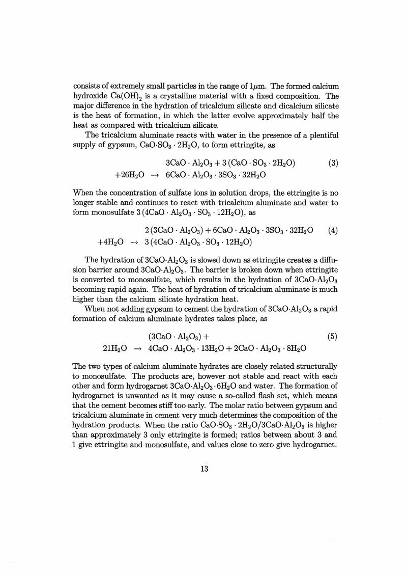
consists of extremely small particles in the range of 1j.Lm. The formed calciumhydroxide Ca(OH)2 is a crystalline material with a fixed composition. Themajor difference in the hydration of tricalcium silicate and dicalcium silicateis the heat of formation, in which the latter evolve approximately half theheat as compared with tricalcium silicate.
The tricalcium aluminate reacts with water in the presence of a plentifulsupply of gypsum, CaO·S03 · 2H20, to form ettringite, as
3CaO· A120 3 + 3 (CaO· 803 · 2H20) (3)
+26H20 --t 6CaO· A120 3 · 3803 · 32H20
When the concentration of sulfate ions in solution drops, the ettringite is nolonger stable and continues to react with tricalcium aluminate and water toform monosulfate 3 (4CaO · A120 3 · S03 · 12H20), as
2 (3CaO· A120 3) + 6CaO· A120 3 · 3803 · 32H20 (4)
+4H20 --t 3 (4CaO· A120 3 · S03· 12H20)
The hydration of 3CaO·A120 3 is slowed down as ettringite creates a diffusion barrier around 3CaO·A120 3. The barrier is broken down when ettringiteis converted to monosulfate, which results in the hydration of 3CaO·A120 3becoming rapid again. The heat of hydration of tricalcium aluminate is muchhigher than the calcium silicate hydratian heat.
When not adding gypsum to cement the hydration of 3CaO·A120 3 a rapidformation of calcium aluminate hydrates takes place, as
(3CaO · A120 3) + (5)21H20 --t 4CaO· A120 3 · 13H20 + 2CaO · A120 3 · 8H20
The two types of calcium aluminate hydrates are clasely related structurallyto monosulfate. The products are, however not stable and react with eachother and form hydrogarnet 3CaO·A120 3·6H20 and water. The formation ofhydrogarnet is unwanted as it may cause a so-called flash set, which meansthat the cement becomes stiff too early. The molar ratio between gypsum andtriealeium aluminate in cement very much deterrnines the compositian of thehydration products. When the ratio CaO·S03 · 2H20/3CaO·A120 3 is higherthan approximately 3 only ettringite is formed; ratios between about 3 and1 give ettringite and mono·sulfate, and values elose to zero give hydrogarnet.
13

When monosulfate is brought into contact with a new source of sulfateions, then ettringite can be formed again, which can cause damage in themicrostructure of cement-based materials. Therefore, cements having lowcontents of 3CaO·Al20 g are used in environments where sulfate ions arepresent.
The reaction of the ferrite phase 2CaO·Al20g·Fe20g can be described withthe same type of reaction sequence as for tricalcium aluminate in the preseneeof gypsurn. The reaction is, however, slower and evolve less heat; furthermore, the gypsurn retards the ferrite reaction more drastically as comparedto the tricalciurn aluminate reaction. Moreover, the hydrationrate becomesslower when the iron content in cement increases.
The composition of an ordinary Portland cement (OPC) consists of approximately 55 wt. % tricalciurn silicate 3CaO·Si02 , 20 wt. % dicalciumsilicate 2CaO·Si02, 12 wt. % tricalciurn alurninate 3CaO·AI20 g and 9 wt.% tetracalcium alurnino-ferrite 2CaO·Al20g·Fe20g. A rapid hardening OPCcement has sometimes substantially higher content of tricalciurn silicate ascompared to normal hardening OPC. However, a rapid hardening cementcan also be obtained by grinding the normal clinker to a higher specific surface area. A low heat cement (low heat of hydration) is obtained by a lowercontent of tricalciurn silicate and a higher content of dicalciurn silicate ascompared to the composition of OPC. In the so-called sulfate resistant Portland cement, the content of tricalciurn alurninate is kept below about 3.5 wt.%.
The use of pozzolans together with pure cement is very common. Thepozzolans most used are ground granulated blast furnace slag, silica furne,which is a by-product of the production of silicon or silicon alloys by reducingquartz in an electrical furnace, and flyash which is the inorganic residue thatremains after powdered coal has been burned and is trapped by electrostaticprecipitators. Silica furne contains approximately 85-95 wt. % amorphousSi02 and the particle size is typically in the range of O.Ol-lj.Lm. Flyashcontains 50-60 wt. %amorphous Si02 and the particle size is in the range of1-100jlm [3]. The pozzolans react with the calciurn hydroxide formed fromthe cement hydration to form new cement gel according to the principalreaction
(6)
As for the cement, the particle size of pozzolans is one of the factors determining the reactivity with water. The smaller the particle size, the faster
14

the hydration. Pozzolans with small particle size improve the workability ofthe fresh concrete without an undue increase in the water demand. Whenthe pozzolan is mixed with Portland cement, it will react with the calciumhydroxide formed during hydration. The effect is then to increase the proportion of cement gel in the hydrated paste at the expense of calcium hydroxide.The cement gel content in hardened concrete is the main factor contributingto strength; therefore pozzolans together with cement are almost always usedin high strength concrete.
Besides the mineral admixtures in concrete, such as pozzolans, chemical admixtures are often used to improve certain properties. Chemical admixtures can be divided into four different groups, (i) water-reducing admixtures, (ii) retarding admixtures, (iii) accelerating admixtures and (iv)air-entraining agents.
The water-reducing admixtures are added to fresh concrete in order tokeep particles from flocculating. If too much water is tied up in agglomerations and/or being adsorbed on solid surfaces, less water is available toreduce the viscosity of the fresh paste and hence of the concrete. Molecules ofthe water-reducing admixtures interact with the cement particles, water andaggregates in away that makes the particles repel each other due to residualcharges. The effect is that particles remain fully dispersed in the paste andless water is involved in agglomerations. The use of water-reducing admixtures thus makes rnixtures containing small quantities of water in relation tocement have the desired properties in terms of fluidity and homogeneity of thefresh concrete. Small content of mixing water in relation to cement content,i.e. low water to cement ratios, is desirable since it increases the strengthand the impermeability of hardened concrete. Three categories based onthe general active ingredients of water-reducing admixtures are (i) salts andderivatives of lignosulfonates, (ii) salts and derivatives of hydroxy-carboxylicacids, and (iii) polymetric material. Most conventional admixtures achievewater reductions of 5-10%; with newer admixtures called superplasticizers areduction of 15-30% can be achieved while still obtaining the desired workability of the fresh concrete. Typically 0.5-2.0 percent of active solid components in superplasticizers by weight of cement is used. High contents ofwater-reducing adrnixtures should not be used, since it may effect the formedcalcium-silicate-hydrate products in a negative manner.
Retarding admixtures can be used whenever it is desirable to offset theeffects of high temperatures, due to hydration, which decrease setting times.The admixture can be divided inta four groups based on the chemical com-
15
position, (i) lignosulfonic acids and their salts, (ii) hydroxylic acids and theirsalts, (iii) sugars and their derivatives, and (iv) inorganic salts. It is observedthat categories (i) and (ii) also possess water-reducing properties. Researchon the effect of retarders has shown that they slow down the rate of earlyhydration of tricalcium silicate. One hypothesis is that retardation arisesfrom adsorption on the hydration products.
Accelerating admixtures are beneficial during winter concreting by partially overcoming the slower rate of hydration caused by low temperaturesand shortening the period for which protection against damage by freezing isrequired. Most soluble inorganic salts will accelerate the setting and hardening of concrete to some degree, with calciurn salts being most effective. Oneof the most effective accelerators is calciurn chloride whose use, however,should be avoided since it increases the rate of corrosion of metals embeddedin concrete.
Air-entraining agents are used to create air bubbles in the paste of concrete which acts as frost protection. The air content must be in the range of4 to 8% by volurne of concrete to obtain satisfactory action. The air-voidsshould be small, in the range of 0.05-1.25 mm diameter, and the bubble spacing should not exceed about 0.2 to 0.25 mm. Air entrainment increases theworkability of an otherwise similar concrete. This allows the water to cementratio to be decreased and can, therefore, partlyor wholly offset the loss instrength arising from the presence of air voids. Air-entraining agents can becompounds such as sodium salts of fatty or alkyl aryl sulfonic acids.
Aggregates generally occupY about 70 to 80% of the volume of concreteand can therefore be expected to have an important influence on its properties. The porosity of the aggregate should be very low, i.e. in the range of0-1%. Higher porosities of the aggregate should be avoided since they lowerthe strength, and increase the risk of frost damage. Further, aggregates thatare inert with respect to chemical reactions with the paste should be chosen. The particle-size distribution or grading of an aggregate supply is animportant characteristic because it determines the paste requirement for aworkable eonerete.
At nearly all conditions, pores of hardened concrete contain liquid water.This water, referred to as the pore solution, contains different types of ionsdepending on the composition of the solid hydration products in contactwith the pore water and on ions penetrating the concrete from outside. ThepH-value in pore solutions is generally very high, i.e. in the range of 13-14.The concentrations of K+, Na+ and OH- in the pore solution of an ordinary
16

Portland cement (OPC) concrete with a water to cement ratio around 0.40are typically 750, 120 and 860 mmol/l, respectively. Other ions such as Ca2+also exist in the pore solution in significant concentrations. A sulfate resistantPortland cement (SRPC) concrete, which contains about half of the quantityof alkali sulfates and less tricalcium aluminate as compared to an OPC basedconcrete, with a water to cement ratio around 0.40, has typically 450, 40 and480 rornol/l of the ions K+, Na+ and OH- in the pore solution, respectively.Adding pozzolans to cement significantly lowers the concentrations of mainlyK+ and OH- in the pore solution of a hardened concrete.
The total porosity of fully hydrated 'standard' cement concrete dependsmainly on the cement content and the water to cement ratio. As an example,in a concrete with the water to cement ratio 1 and the cement content 175kg/m3 without air-entrainment, the total porosity is in the range of 0.16-0.17,and for the water to cement ratio 0.5 and the cement content 370 kg/m3 thecorresponding value is in the range 0.13-0.14. Additional contribution to theporosity must be considered when using air-entraining agents or/and whenthe aggregate used has a significant porosity. The shape of the porosityin material is such that vapor in the air-filled space can penetrate into thematerial at a slow rate. In the same manner ions dissolved in a pore solutioncan penetrate through the pore system.
The cement gel itself has a very high specific surface area. Using the BETequation on sorption measurements with water vapor, the approximativevalue of 195 m2/g is obtained for cement paste with the water to cementratio 0.5. Using a plate shaped geometrical model and assuming that the gelporosity is 0.28 and that the compact density of gel is 2460 kg/m3 , the meanpore size in gel can be estimated to be about 13 Å and the mean thicknessof gel 'plates' to be about 32 Å. The microstructure in terms of the specificsurface area is an important property determining the extent and rate of massexchange of ions in a pore solution and ions involved in the solid componentsof the hydrated cement paste.
17
3.2 A short revieW' of :rnechanisInS of degradation ofreinforced concrete structures
The reports and papers presented in this work deal with only a few of theservice life related problems of concrete structures. The main content to bepresented is related to the description of some of the most common types ofions in pore solutions and properties of solid constituents in cement-basedmaterials.
3.2.1 Chioride penetration and reinforcelIlent corrosion
Concrete structures in marine environments or constructions subjected tode-icing salt agents suffer a considerable risk of being degraded due to reinforcement corrosion. The penetration rate of chloride ions into concretedepends on, among other things, the water to cement ratio, cement and pozzolan content and the moisture condition in the structure. The corrosionrate is very much related to the condition of the pore solution near the reinforcement bars, mainly in terms of the concentrations of chloride ions andhydroxide ions. The oxidation reaction in the corrosion process involves thedissolution of iron in the pore water near the steel, written as
Fe(s) ----+ Fe2+(aq) + 2e- (at the anode) (7)
where e- denotes an electron. This reaction may only occur if the depassivation of the steel has been induced, for example by the presence of chlorideions in the pore solution at a sufficiently high concentration (presumablycaused by breaking the oxide film on the steel surface) or/ and a decreasein the basicity. The threshold chloride concentration required for onset ofcorrosion has not been fully clarified. It probably depends on such factorsas the OH- concentration of the pore fluid surrounding the bar and the O2
concentration around the bar, and factors that affect the electrical potentialof the steel [4].
Incoming electrons from the steel bar at the cathodic area form hydroxideions in the presenee of water. The oxygen reduction reaction is
Apparently, the rate of the induced reaction is very much deterrnined bythe concentration of the hydroxide ions in the pore solution near the steel.
18

The hydroxide ions that are liberated in the cathode area are balanced by areaction in the anodie region, to form ferrous hydroxide, Le.
(9)
Since the hydroxide ions liberated at the cathode can be transferred throughthe electrolyte, in this case the pore solution, the How properties of the hydroxide ions in the pore solution near or at the interface between the concreteand the steel are of importance. The ferrous hydroxide will, furthermore, react with available dissolved oxygen or oxygen in its gaseous phase to formhydrated red rust Fe(OH)3:
4Fe(OH)2(S) + 02(aq or g) + 2H20 ~ 4Fe(OH)3(S) (anode) (10)
where, again, the availability of oxygen and liquid water are important forthe reaction rate. The expansion of the corrosion products induces cracks inthe concrete surrounding the bars.
3.2.2 Carbonation of hydration products in concrete
Carbon dioxide in air penetrates the concrete pore system and dissolves in thepore solution. The carbonic acid formed will react with solid products suchas calcium-hydroxide. Depending on the cement type used, the porosity caneither decrease or increase. The final result of the several steps through whichthe calcium carbonate is formed can be described simply by the followingreaction:
Carbonation reduces the hydroxide ion concentration in the pore solution,which is a negative factor with regard to reinforcement cOITosion since thesteel surface becomes de-passivated.
3.2.3 Leaching of hydroxide from a pore solution
The leaching process slowly breaks down the solid calcium hydroxide andcement gel in the hydration products of concrete. The leaching process isalways active when concrete is in contact with water containing low concentrations of hydroxide ions. The leaching can simply be described as
(12)
19

The hydroxide leaching from the pore solution in concrete can be considerablyhigh when externa! water pressures acts on a construction such as in concretedams, e.g. see [5].
3.2.4 Sulfate Attack
Concrete in contact with sulfate ions will suffer a risk of being degraded.Sulfate attack is due to sulfate ions from external water penetrating theeonerete; the sulfate ions react mainly with the hydration products based ontricalcium-aluminate. The products formed, such as gypsumand ettringite,make the material expand due to microcracking. Cements low in alurninateare regarded as being sulfate resistant. One of the main reactions valid duringsulfate attack, causing ettringite formation, is
4CaO· Al20 g • 803 • 12H20 + 2 (CaO· S03 · 2H20) (13)
+2H20 ~ 6CaO· Al20 3 • 3803 • 32H20
This is accomplished by a very large increase in solid volume, which causesvolume expansion within paste and which generates accompanying internaIstresses and ultimately leads to cracking.
3.2.5 Paste-aggregate reactions
The most common case of paste-aggregate reaction is the alkali-siliea reactionwhich is caused by aggregates containing amorph 8i02 , which is sensitive forreaction with the ions in the alkali rich pore solution. A thin zone of reactionproducts is formed around the aggregates, the so-called alkali-silica gel. Thealkali-silica gel formed expands when exposed to high moisture conditiollS.The damage caused by alkali-silica reaction is sometimes observed as popouts at the concrete surface. Destructive expansion also occurs in concretesmade with some aggregates containing dolomite, which reacts with hydroxideions in a pore solution.
3.2.6 Freeze thaw damage
Due to the expansion of water in a pore system when frozen, the concretecan be damaged. The damage depends on the degree of water saturation ofthe pore system, the amount of air bubbles in the material and the spacingbetween them, e.g. see [6]. Often factors like the water to cement ratio and
20

the aggregate porosity also plays a significant role. Special attention musttherefore be paid to concrete constructions used in cold moist climates.
3.2.7 Salt frost scaling
Special types of damage in concrete can occur if freezing is active whensimultaneously having a salt solution present at the surface of the material.A· typical case is when using de-icing salt agents at low temperatures. Theobserved damage during this situation is that thin flakes at the concretesurface are spalled off. The phenomenon can be explained by the fact thatchiorides penetrate the concrete slowly as compared with the temperaturedecrease in the material. Since the salt in a pore solution lowers the freezepoint temperature, the first ice is formed at a depth which is greater than thedepth at which a significant salt concentration can be detected. The changesin expansion at the surface and just beneath the surface of the material makesthin flakes spaIl off, see [7]. Other mechanisms for the salt frost scaling hasalso been proposed, e.g. see [7].
3.2.8 Degradation caused by mechanical loads
Effects on concrete structures due to dead and variable loads include for example, cracking, creep and wear. The mechanically induced damages canbe accelerated when constructions are simultaneously subjected to other destruction mechanisms such the ones mentioned above.
3.2.9 DaIIlage induced by thermal effects and Inoisture conditions
Environmentally induced strains caused by a change in temperature and/ormoisture condition can cause damage often visible in the form of eraeks. Suchdamage can be avoided by using construction joints and a proper arrangementof the reinforcement bars. A model based on fracture mechanics has beenestablished describing the effect of moisture and temperature changes onconcrete [8].
3.2.10 Durability conditions of concrete structures related to theproduction stage
If the heat of hydration in heavy constructions is not properly accounted for,the risk of obtaining cracks is substantial. Low heat cements and/or cooling
21

systems are often used. Drying of the concrete during the early hydrationperiod can cause damage. Insufficient compaction during casting is a commonproblem causing unwanted nonhomogeneities in the structure. Design issuessuch as avoiding accumulation of water during construction, and placing thereinforcement bars at sufficient depths from surfaces, should be considered.
22
3.3 Chioride ingress in concrete
3.3.1 Transport of ions in the pore solution of hardened concrete
Nearly all deterioration processes of reinforced concrete structures are associated with the amount of pore liquid and the condition of the pore solution interms of concentrations of different types of ions, e.g. see previous sections.Therefore it is important to try to understand the underlying mechanismswhich determine the changes of concentrations in pore solutions due to diffusion and chenrlcal reactions. Some of the most common mechanisrns affectingthe condition of the pore solution are listed below
1. Concentration gradient driven diffusion: The most important properties affecting the diffusion of ions in pore solution of concrete areporosity and the degree of water saturation in pores, shape of poresystem and presence of nrlcrocracks and other nonhomogeneities. Oneof the 'forces' contributing to a mass density fiow· of ions dissolved inpore solution is the concentration gradient. The diffusion resistanceof the ions increases when the concentration of liquid water in a poresystem decreases. Diffusion of vapors in the air filled space of concrete,in which oxygen and carbon dioxide are most important, are affectedby the liquid water concentration in the opposite direction as comparedwith the dissolved ions in a pore solution.
2. Binding: The physical or chenrlcal binding of ions, from external sources,onto inner material surfaces in concrete, such as chloride binding, aredependent on many different factors. Properties affecting binding arethe specific surface area of solid hydration products, the chenrlcal composition of solid hydration products, and the composition of the poresolution. The binding of ions from pore solution should be incorporated into models dealing with diffusion, since the process changes theconcentration in the pore solution.
3. Leaching: Describes the process of solids being broken down and dissolved in the pore solution. The most common leaching in cementbased materials is the decalcification of the solid calcium hydroxide inconcrete, i.e. the dissolution of calcium ions and hydroxide ions intothe pore solution. The conditions in both the pore solution and in thesolid components of concrete are changed.
23

4. Convection of ions: Capillary suction of externa! water can force dissolved ions in a pore solution to be moved in the direction of the capillary flow. Drying of concrete surfaces may force ions to be movedin the direction of the surface. The drying is however mostly due tomovement of water vapor in the air filled pore space not affecting theeonveetive How. Henee a correct deseription of the How charaeteristicsof the liquid water phase becomes essential when including convectionof ions dissolved in a pore solution.
5. Diffusion of ions induced by internal dielectric effects: As pointed outin previous sections, the pore solution in contact with solid hydrationproducts in concrete always contains significant concentrations of different types of ions. It can be postulated that different ions, of positiveand negative charge, must diffuse in the pore system in away thatthe net charge in every material point and at every time level is closeto zero. This means that not only the concentration gradient and theconvective driven flow of ions should be considered, but also a forcerelated to the charge character of the mixture of all different types ofions present in a representative volurne of the pore solution.
6. Water saturation: The degree of water saturation not only determinesthe diffusion resistance of ions dissolved in a pore solution. The drying process means that the ion coneentration in the pore solution isincreased, and that an increase of water content in material results inthe pore solution becoming more dilute. This effect can be modelledin a direct manner if relating the ion eoncentration in pore solution tothe volurne of pore solution and not to the total volurne of material.
7. Diffusion caused be extemal electrical forces induced by reinforcementcorrosion: A corrosion current is active during the propagation stageof reinforcement corrosion. The indueed electrica! field will affeet ionsin a pore solution loeated in domains surrounding the corrosion zoneincluding both the eathodic and anodic areas. All different kinds ofions present in the pore solution within the corrosion zone will, in thiscase, be subjected to a force making the diffusion behavior markedlydifferent from normal situations not ineluding active eorrosion.
8. Clogging of pores due to hydration and crystallization: During the earlystage of eonerete, properties such as porosity and speeifie surface area
24

are significantly and rapidly changed with time. The diffusion behaviorof ions during this period is, therefore, also affected. Even for weil curedconcrete the binding and leaching process can affect the pore structurein away that the diffusion resistance in a pore solution is affected.
3.3.2 Diffusion of a mixture of different types of ions coupled tomoisture transport in concrete
Most concrete constructions subjected to harmful ions such as chlorides, sulfates and carbonic acid are also exposed to variations in moisture content.Phenomena such as capillary suction and drying will affect the diffusion ofdifferent types of ions dissolved in a pore solution. A stringent model of thisproblem should result in one equation for each type of ion appearing in apore solution, one equation describing the moisture transport and one equation for each solid component being formed from ions in the pore solution orbeing dissolved into the pore solution from solid components.
The basic concept behind the so-called rnixture theory will be used, e.g.see [9], in order to establish a model describing diffusion of a rnixture ofdifferent types of ions in a pore solution of eonerete, and its couplings to themoisture condition and moisture flow. Each constituent is assigned a massdensity concentration. The mass density concentration of the i = 1, ... , ~dissolved ions considered in pore solution will be denoted rJ: (kg/m3) and thes = 1, ... ,~ solid precipitated combinations of ions in pore solution will bedenoted pr;. The h = 1, ... , Nsolid components of the concrete will be denotedPh' and the mass density concentration of liquid water in the material volumewill be denoted rI:v. The total mass density of the rnixture p is the sum of allconstituents. Two phases will be considered, the pore solution phase p andthe solid phase of the concrete c. Reactions within and between the phaseswill be considered in the general case. The only balance principle that willbe considered are the mass balance equations for the constituents, the twophases and the whole rnixture, i.e. the momentum balance equation, energybalance equation and the second axiom of thermodynamics are ignored inthis presentation.
It will be seen that the complexity of the problem considered grows drastically as compared to, for example, the isothermal moisture transport problemwhich only includes one mass balance principle and one constitutive equation,e.g. see section 3.4.1.
The mass density concentration of solid component phase pC, i.e. the 'dry'
25

concrete density, is the sum of the ~ number of individual solid constituents,i.e.
N
pC = LPh (14)
h=1
where Ph is the mass density concentration of the h:th solid component.The mass density concentration of the pore solution phase pP is the sum
of the ~ nurnber of dissolved ion constituents, the surn of the ~ nurnber ofsolid precipitated combinations of ions and the water itself, i.e.
~ 9
tf=Lpf+L~+~i=l s=l
(15)
(17)
(18)
(19)
where pf is the mass density concentration of the i :th dissolved ion constituent, pr; is the mass density concentration of the s:th precipitated constituent in pore water phase and rJPw is the mass density concentration of the'pure' water in material. The total mass density concentration of the mixturepis
N ~ 9
P = pC + tf = L Ph + L pf + L ~ +~ (16)
h=l i=l s=l
The mean velocity of the pore solution phase xP is defined as the massweighted average of individual constituent velocities Xf (mis), x~ and x~, i.e.
1 ~ 1 9 AJ 'pxP = - LpfXf + - L~xr; + vwxw
pP i=l pP s=l pP
The mixture velocity of the solid phase XC is the mass weighted average ofindividual solid constituent velocities Xh' i.e.
·c 1 ~ c'cX = -; L....J Phxh
P h=l
The velocity of the whole mixture x is defined to be the sum of xP and xc,that is
1 ~ 19 AJ' IN• . """ r1J ' """ r:P ' Ifw X
w """ c'X=- L....J Pi Xi + - L....J Psxs +-- + - L....J PhXhP i=l P s=l P P h=l
In a general case where xh is different from zero, the mass balance principlefor the N nurnber of solid constituents of the concrete phase c can be writtenas
26
(21)
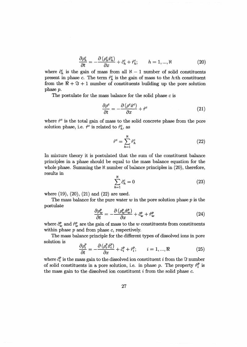
8Ph 8 (Phxh) ~c ~c h ~~ (20)åt = - ax + ch + rh; = 1, ... , 1'1
where ch is the gain of mass from all ~ - 1 number of solid constituentspresent in phase c. The term f h is the gain of mass to the h:th constituentfrom the ~ + ~ + 1 number of constituents building up the pore solutionphase p.
The postulate for the mass balance for the solid phase c is
8pC a(pCXC) ~c
åt = - ax +r
where f C is the total gain of mass to the solid concrete phase from the poresolution phase, i.e. f C is related to f h, as
(22)
In mixture theory it is postulated that the sum of the constituent balanceprinciples in a phase should be equal to the mass balance equation for thewhole phase. Summing the ~ number of balance principles in (20), therefore,results in
(23)
where (19), (20), (21) and (22) are used.The mass balance for the pure water w in the pore solution phase p is the
postulatea~ __a(~x~) f!!. Ap (24)åt - ax + w +rw
where c~ and f~ are the gain of mass to the w constituents from constituentswithin phase p and from phase c, respectively.
The mass balance principle for the different types of dissolved ions in poresolution is
ad = a(di!/.) + ~ + ~1!. ~ (25)åt ax Gi "i, i = 1, ... , ~n
where f!! is the mass gain to the dissolved ion constituent i from the ~ numberof solid constituents in a pore solution, i.e. in phase p. The property Tf isthe mass gain to the dissolved ion constituent i from the solid phase c.
27

The mass balance principle for the solid precipitated neutral combinationsof ions in pore solution is
8rY: _Bt-
8 (rY:x~) + f!!. + fP.8x s s'
s= l, ...,~ (26)
where c~ is the mass gain to the solid constituent s in the pore solution fromthe i number of dissolved ions also present in the pore solution. The term f~
is the mass gain to the solid constituent s in the pore solution, i.e. in phasep, from the solid phase c.
The mass balance for the whole pore solution phase p is the Postulate
8PP _at- (27)
where fP is the total gain of mass from the solid phase c, i.e.
(28)
The sum of equation (24), the ~ number of equations in (25) and the ~
number of equations in (26), should result in satisfying condition
~ ~
Lcr+L~+cw=O,i=l c=1
(29)
since it is postulated that equation (27) is the sum of the constituent equations in phase p.
The postulated mass balance for the whole mixture, including both thepore solution phase p and the solid phase c, is
8p __ 8 (pi:)åt - 8x (30)
Summation of the mass balance equations for the c and p phases, i.e. equation(20) and (27), results in the relation
(31)
where (17), (18) and (19) are used.
28

(32)
Yet another balance principle will be invoked for the pore solution phasep, the continuity equation for the charge, which is
adP-=qPax
where the electrical displacement field is denoted by d (C/m2) and the chargedensity with q (C/m3). This equation will controi the condition of the poresolution in terms of an electrical potential '{J. The reason for obtaining anelectrical potential in a pore solution is a momentarily unbalancing numberof positive and negatively charged dissolved ions in a representative volumebeing much larger than the size of the ions themselves.
In this application it is convenient to introduce the so-called diffusionvelocity, which is the velocity of a constituent in relation to the phase mixturevelocity.
P ..Lp.pUi - Xi - X
U Ch ~c x·c- Xh-
(33)(34)
It will be explicitly assumed that different dissolved ions in a pore solutioncannot react with each other, Le. the problem will be restricted to a casewhere precipitation of combinations of ions cannot occur. This means thatthe mass exchange terms f!l (x, t), i = 1, ... ,~ are set to zero. The unknownquantities for the ~ number of different types of ions dissolved in the poresolution, therefore, are
rJ: (x, t) ; uf (x, t) ; Tf (x, t) ; i = 1, ...,~ (35)
where rJ: is the mass density concentration of an arbitrary type of ion dissolved in the pore solution, uf is the corresponding diffusion velocity, i.e. thevelocity of the ion type i in relation to the velocity of the phase rnixture, i.e.in relation to xp •
For the 'pure' water in a pore solution it will be explicitly assumed thatc~ (x, t) = o. Furthermore it will be assumed that r~ (x, t) = 0, i.e. effectssuch as loss of water due to hydration or gain of water due to carbonationwill not be included in the model. The unknown properties left for the 'pure'water in the pore solution are
rJ:v (x, t) and x~ (x, t)
29
(36)
For the ~ number of solid components in the pore solution phase p, denoted by a subscript s, it will be assumed that the velocities s = 1, ... ,~ arezero, i.e. x~ (x, t) = O, and that no mass exchanges take place within thephase or between the two phases, Le. c~ (x, t) = O and r~ (x, t) = Ofor alls = 1, ... ,~ constituents. This means that the mass densities for the precipitated combinations of salts in a pore solution will be entirely given by itsinitial values. For simplicity these initial values will be set to zero.
The properties of the solid constituents in concrete will be restricted inthe sense that the velocities for N number of constituents are set to zero,Le. xh (x, t) = O. Further, no reactions between the ~ number of solidconstituents within the phase c will be included, i.e. Ch (x, t) = o. Theunknown properties of the solid constituents in phase c, therefore, are
p~ (x, t) ; r~ (x, t) ; h = 1, ... ,N (37)
The unknown properties for the whole mixture, including both phase p andc, are
p (x, t) ; x(x, t) (38)
where p and x are defined in (16) and (19).In order to study the influence of the charge of the different kinds of ions
in the pore solution phase on the diffusion behavior, the electrical potential'(iP (V), the electrical displacement field dP (C/m2) and the charge densityqP (C/m3) must be added to the list of unknown properties in the problemstudied.
'(iP (x, t) ; dl (x, t) ; qP (x, t) (39)
The number of unknown properties in the reduced problem is 7 + 3~+ 2~.
With the above assumptions the balance principles for the constituentsare simplified. For the solid components in the phase c, one obtains the massbalance equation
8~h = rh; h = 1, ... ,~ (40)
The simplified mass balance equation for the pure water constituent becomes
8fJfv 8 (fJfvx~)at = - ax
30
(41)

The mass balance for the ~ number of dissolved ions in the pore solution are
ap'f __ a (p'f1!l) Tr'ät- ax +~, i = 1, ...,~ (42)
The conditions imposed by the mass balance for the whole rnixture imply thatno net production of mass can take plåce during mass exchange between° thetwo phases. That is, the mass balance condition
~ N
~Tf+ LTh=Oi=l h=l
(43)
must hold.The last balance principle considered is the condition for the electrical
potential, which isådPax = et (44)
In the application to be presented it will be of interest to use a mol densityconcentration definition of the ion constituents dissolved in pore water, instead of the mass density concentration definition. The relation between themass density concentration Pa and the mol density concentration nf (mol/m3 )
is(45)
(46)i = 1, ...,~,
where mi (kg/mol) is the mass of one mol of the i:th constituent which is aconstant property. By definition (45) the mass balance equation for the ionconstituents (42) can be written
ånf _ 8 (nf1!l) AP.mi ät - -mi ax +mini l
(47)i = 1, ...,~,
where the mass gain density to the i:th constituent Tf is related to the molgain density na (mol/(m3s)) as nf = Tf/mi. That is, the mass balanceprinciple for the ion constituents (46) can be written as
ånf _ å (nf1!l) AP.ät - - ax +nil
This equation will be rewritten in yet another way in order to facilitatethe description of the diffusion velocities of the different types of dissolvedions. Consider the concentration dl (-) of the ion constituents, defined as
31

c!l = rJ:/ pP = nfmi/pP (48)
This defuiition together with equations (33) and (42) can be combined toyield
a(c!lpp) _ a(rJ:uf) a(c!lppxP ) f?åt - ax - ax + il
Partial differentiation of the terms
andå (c!lppxP ) _ -'På (ppxP ) ,3) .påc!l
ax - <; ax + p x axmakes it possible to write equation (49) as
i = 1, ...,~ (49)
(50)
(51)
å (rJ:uf)åx
i - 1, ...,~
(52)
The first term on the left-hand side of (52) can be identified by help fromthe mass balance equation for the phase p, i.e. equation (27), as
c!: (app + a(PPXP)) = c!:fP = c!:~ f?
~ åt ax ~ ~ ~ ~~=1
(53)
i = 1, ... ,~ (54)
where (27) with f~ = O, for s = 1, ...,~, and f~ = Oare used. The equations(52) and (53) combine to yield
"p ad/. = a(rJ:ur) _ "p. p ad/. f? _ rJ: i:tl Tf .p åt ax p x ax + t pp'
Using the mol density concentration, as defuied in (45), instead of theconcentration Ca, the equation (54) takes the form
(55)
i - 1, ...,~
32

PartiaI differentiation of the term
a(nf/pp) 1 ånf nf appax = pP ax - (pp)2 ax
and
(56)
(57)å(nf/pp) 1 ånf nf åPP
at = pp 7ft - (pp)27ft
in (55) means that the mass balance equation for the ions dissolved in porewater can be written as
i - 1, ...,~
ånf nf åPP----- -åt pp åt
p ""'~ -~PA P ni L.,.,i=l 1in·- .
't pp'
1 å (rJ:uf) .pånf nf±Papp----x -+----+
mi ax ax pp ax (58)
The assumption that the mass density concentration for the pure waterphase is much greater than any of the mass density concentrations of thedissolved ions will be used, i.e.
raP » rJ! ·I-'w Pi=l,...~, (59)
This results in the mean velocity of the pore solution phase ±P being approximately equal to the velocity x~ of the pore solution, i.e. campare with (17).Furthermore, the mass density of the pore solution phase is approximatelyequal to the mass density of pure water, i.e. the approximation in (59),results in
(60)
The approximative version of the balance principle for the ion constituentsin pore solution becomes with (60)
i - 1, ...,~
for all ~ considered ions. It is noted that the term
nr 2:~1 Tf = rJ: 2:~1 Tf ~o{Jfn mi{Jfn
33
(61)
(62)

in (58), is approximately zero due to the conditions in (60).Consider the mass balance equation for the pure water constituent, i.e.
(41), written as
nf afJfv nf a (fJfvi~)Pfn åt = - Pfn 8x
i.e.p ar:P P'P anP ~ 'pni Vw nixw Vw puxw-- = ----- - n·--Pfn at Pfn åx 2 åx
This means that the ~ equations in (61) can be written as
(63)
(64)
an1!_2 _
åt - i = 1, ...,~ (65)
(66)
The term nfaxw /8x, in equation (65), represents the change in the massdensity concentration of ion i in a pore solution due to a change in themass density concentration of the pore solution caused by drying or capillarysuction. To show the meaning of the term n'faxw / ax, consider again themass balance for the 'pure' water in the pore solution phase, i.e.
8fJfv = _ 8 (fJfvx~) = -xv 8fJfv _ ~ 8x~at ax w ax w ax
I
Note that the material derivative of fJfv, denoted (fJfv) , is the change in massdensity concentration related to the motion x~ given as
(67)
That is, by combining (66) and (67), the mass balance equation using thematerial description becomes
I aiP(~) =-~ 8: (68)
This means that the ratio between the change in mass density concentrationof the pore water, following its own motion, and the actual mass densityconcentration is proportional to ax~/ax, i.e.
I
(fJfv) _ _ai~
Pfn - ax
34
(69)

(70)
Hence term nf8xw/8x = nr (rffn)' / Pw is the absolute change of the massconcentration of ion i dissolved in a pore solution, following the motion ofthe pore water.
Next, consider the constitutive relations for the constituents. The velocityof the pore water in material is the assumption .
'P _ D~ (rffn) årffnX w - - Pf» 8x
where D~ (rffn) is the nonlinear material parameter relating the gradient ofthe mass density concentration of water in pores with the velocity x~. Theexperimental methods described in sections 3.4.4 and 3.5.1, together witheither of the evaluation methods described in sections 3.4.1 or 3.4.2 can beused to obtain the function D~ (~).
The assumptions for the diffusion velocity flows for the ~ considered typesof ions in a pore solution are
i = 1, ...,~ (71)
where iJf (Pw) (m2/s) is the diffusion parameter for ion type i in the poresystem which is assumed to be dependent on the moisture condition Pw. Theproperty Äf (rffn) (m2 / (Vs)) is the ion mobility parameter for ion type i inthe pore system. The valenee number for ion type i (to be used with thecorrect sign) is denoted by Vi (-), and cp (V) denotes the electrical potentialin the pore solution.
The mass exchange rate for the ion type i with solid constituents can,in a somewhat general case, be described as functions of all 3? number ofmol density concentrations of the different types of ions in phase p and all Nnumber of mass densities of solid components in phase c. The mol densitygain of mass to the i:th ion constituent dissolved in a pore solution from thesolid phase is written as
nf = Ii (nf=l,.../Rl Ph::l, ...9) (72)
And the mol density gain of mass to the h:th constituent in solid phase fromions in the pore solution is written as
(73)
35

(74)
where it should be noted that the function Ii is related to Ih through thechemical reaction assumed to be taking place.
The assumption for the electric displacement field dP in a pore solution is
at = -eco 8<påx
where Co (CIV) is the coefficient of dielectricity or permittivity of vacuum,Co = 8.854 · 10-12 , and e (-) is the relative coefficient of dielectricity thatvaries among different dielectrics. For water at 25°0, e= 78.54.
The charge density in a pore solution is the global unbalanee of charge ina material point given as
~
et = Fz=nfvii=1
(75)
where F = 96490 (O/mol) is a physical constant describing the charge of onemol of an ion having a valence number equal to one.
Combining the mass balance (41) and constitutive relation (70) for themass density flow of the water phase, one obtains
(76)
which is the governing equation determining Pfn (x, t) .Combining the constitutive relation (71), for the diffusion velocity for the
ion type i, and the assumption (70) with the mass balance equation (65) for.the same ion type, one obtains
for all i = 1, ... ,~ ion types considered.The equation determining the mass density field Ph (x, t) is obtained by
combining the mass balance equation (40) and the constitutive assumption(73), Le.
8Ph = (n1! ) .at ~h z=l, ...!R' Ph=l, ... r;s ,
36
h= 1, ...,~ (78)
where the function ~h is related to ih, in (73), by the mol weight involved inthe reaction. Explicit expressions describing mass exchanges between ions ina pore solution and the solid hydration products are proposed by constitutiveequations in reports 1:1-3. Examples of such reactions are binding of chloridesand leaching of hydroxide.
The governing equation for the electric potential 'P (x, t) is obtained byinserting the two constitutive assurnptions (74) and (75) into the continuityequation (44), i.e.
_ 82cp R
-€Co 8x2 = F~ naVa (79)
According to the ·mass balance principle for the local mass exchangesbetween pore solution phase and solid phase, i.e. (43), the following shouldalso hold
R ~
L ii (nf=l,... !R l Ph::l, ...SS) = L ih (nf=l,...!Rl Ph=l,...SS) (80)i=l b=l
One of the main ideas behind this method of treating multicomponent iondiffusion in concrete pore solutions is that the diffusion parameters iJf (Pw)and ion mobility parameters Äf for all i:th types of ions considered can bescaled with the same tortuosity factor t, which is assurned to be a functionof the moisture content Pw. That is
i = 1, ...,~
where Di and Ai are the bulk diffusion .and ion mobility coefficient in water,respectively. The values of these coefficients for different types of ions can befound in, for example, [10]. The experimental work concerning the diffusioncharacteristics, therefore, consists of determining only one parameter, i.e.t (Pw) for the material in question. The main experimental and theoreticalwork, due to this choice of approach, is directed more towards describing themass exchanges between ions in pore solution and the solid components ofconcrete, i.e. the description of ii and ih.
In reports 1:1-3 the parameter t (Pw) is evaluated at saturated conditionsfor different concrete qualities. In these papers different mass exchange assurnptions are also included.
In paper 2 the convective driven diffusion due to capillary suction andnormal diffusion of chlorides is examined. A more simplified version of the
37

governing equations than those derived in this section is used; the mainconcept is, however, the same.
The numerical problems associated with the present convective term inthe ~ number of equations shown in (77) are analyzed, for the typicallengthand time scales in the problem studied, in paper 3.
3.3.3 Methods of measurernents of chioride penetration into hardened concrete
Different methods deterrnining the diffusion characteristics of chiorides in thepore system of concrete are discussed in this section. It is noted, however,that it is difficult to perform measurements on the separate mechanisms listedin section 3.3.1. The measured response must rather be seen as a combinedeffect of many different phenomena.
Colorimetric method: One of the first methods adopted to indicate thedepth of penetration of external chlorides into concrete was a simple colorimetric method, e.g. see. It is based on the spraying of fiuorescein (lg/1 ina 70% of ethyl aleohol in water) and then of silver nitrate aqueous solution(0.1 M AgNOs) on the concrete fractured surface area. In the absence ofchlorides, or in the presenee of chernically bound chlorides only, the concretesurfaee becomes dark when exposed to .natural light. In the presenee of freechiorides in a pore solution of eonerete, AgCI is formed whieh produces apink eolor in the presenee of fluorescein.
The method cannot directly be used to identify material constants relatedto the chioride ion diffusion. The method is, however, ideally suited for rapidtesting of the condition of concrete structures.
lon selective electrodes: Samples from conerete are collected by drillingor grinding. The powder is normally stored in a liquid based on a nitric acidwhieh dissolves both free and bound chlorides. A chioride sensitive electrodeis calibrated against several different solutions with known eoncentrationsof chloride. The calibrated electrode measures the voltage for the samplesolution. The reading is converted to a chloride eoncentration given by thecalibration procedure. The chloride eoncentration is often given as masschiorides by concrete mass.
The method deseribed has been used to deteet chlorides in the experiments described in reports 1:1-3.
38

Potentiometric titration: This equipment measures ehloride ion eoneentrations in the interval 10-999 mg Cl- /1. The repeatability is about ±1.5%at an absolute level of 200 mg CI- /1. The ealibration is performed on a 500j.Ll sample at the eoneentration 200 mg CI-/1. A potentiometer is adjusteduntil the eorreet reading is obtained.
During the experiment the ehloride solution to be tested is in eontact withtwo eleetrodes. Silver ions are supplied from the silver anode by applying aeonstant eurrent. When all chloride ions have been eonsumed by the silverions, the same ions increase rapidly in solution and a 'dead stop' funetionstops the eurrent. The time period for having the eonstant current appliedto the solution serves as a measure of the number of dissolved chloride ionsin the test.
Potentiometrie titration has been used as a complementary method tothe ion seleetive electrode, see reports 1:1-3.
X-ray mapping: A scanning electrode mieroscope has been used to detectchiorides in cement paste [7]. Samples were exposed to a 3% NaCI solution forthree hours. The samples were dried in a direction perdenticular to the onedimensionai ehloride diffusion direction. This was done to minimize furtherpenetration of chlorides within the paste. The X-ray mapping of the ehloridepenetrated samples indicated a depth of penetration. However, the concentrations of chiorides in the sample in this experiment were so low that thegeneral noise in the signals effectively shaded the exact chloride profile andhence the exaet penetration depths. The method can probably be improvedfor samples exposed to higher chloride ion concentrations. Further developments of the method are of interest since several types of ions can be deteetedwith the X-ray analysis, whieh means that the effeet of the eomposition ofthe pore solution and the outer storage solution can be studied.
Steady state diffusion cell tests: A conerete dise is placed between twocompartments containing solutions at different coneentrations of ch1orides,e.g. see [12]. The solutions in the two compartments are often saturatedwith Ca(OH)2 to minimize leaehing from the sample. Typieallya 1 M NaCIsolution in saturated Ca(OH)2 is used in the up-stream eompartment anda saturated Ca(OH)2 solution in the down-stream eompartment. The concentrations of chloride ion in the down-stream compartment after variousdiffusion times can be determined by withdrawing small volumes of the so-
39

The governing equation becomes
(86)
where (84) and (85) are used.The experiment can be controlled so that 8cjJ/8x = const. = E, i.e.
a2</J/åx2 = 0, which means that the equation (86) can be written
8pc _ D 82Pc DctzFE 8pc (87)
at - ct 8x2 + RT 8x
where the relation Act = DctzF/(RT) is used.If using a sufficient high applied electrical field, i.e. EzF/(RT) » 1, it
can be motivated to set the pure diffusion term Detå2pc/åx2 = o. For theinitial conditions and applied boundary conditions used in terms of chlorideconcentration and the electrical potential, the sharp penetration front is, inthis case, simply given as
XI = tDctzFE/(RT) (88)
which is the condition obtained from (87) when the applied electrical fieldis sufficiently high. That is, the expression (87) is the integrated version ofthe equation x~ = DctzFE/(RT) which is valid from the given assurnptionstogether with equation (85). The term DetzFEj(RT) corresponds to the'drift' velocity of the chiorides due to the constant electrical 'force' when thepure diffusion, caused by concentration gradients, can be neglected.
By measuring the penetration depth with the colorimetric method whichduring ideal conditions is the xj-value, the diffusion constant Det can becalculated for a given exposure duration t, using equation (88).
It can be argued that some improvements of the model on which theexperiments are evaluated can be made. The strategy is to solve equation(87) analytically with proper boundary conditions in which the Det-valueobtained from equation (88) is used. The penetration depth of chlorides fromthis calculation is compared with the calculated values given from expression(88), see Figure 1.
For the range of electrical fields E adopted in the experiments, the following relation between the ideal penetration depth X I and the penetrationdepth obtained from solving equation (87) has been proposed [13]:
(89)
42

\ '. \\ \, \
0.9I \, \,
l II
0.8,
I , ,I ,
0.7 l ! ,c I , ,o l~0.6
,cQ)(,)c80.5
"'O
~I7ä I
E0.4 I I,
oc I I,
0.3 I , ,I , ,, , ,
0.2 l ,I I, , ,, ,
0.1, ,
\I \, \\\ \
\ \
O \ \ ""O 0.005 0.01 0.015 0.02 0.025 0.03 0.035 0.04 0.045 0.05
x [m]
Figure 1: Schematic illustration of the solutions of equation (21), solid line,and equation (20), dashed line, for given values of the diffusion constant andthe applied electrical field E. A normalized boundary condition has been used.
where the r is a parameter approximately equal to 0.5. If the colorimetricmethod is very sensitive for low concentrations of chlorides, the Xd value canbe used as the measured penetration depth instead of x f . In this case (89)and (88) should be used to calculate Det.
The robustness of the method can be checked in a number of ways. As anexample, the Det-values can be calculated from the experiment at differentexposure times. Obtained differences of these values then serve as a measureof the error in the evaluation technique. Another approach is to measurethe chioride ion profile, after a given exposure duration in the migration cell,which according to the adopted evaluation method should be identical tothe profile given from solving equation (87) with properly applied boundaryconditions.
Total chioride profile tests: Samples from concrete are removed fromcertain distances from the surface previously exposed to a chioride solutionwith constant concentration at entire exposed surface (immersed condition).
43

(91)
The sampling can be performed by using a more sophisticated grinding deviceor simply by drilling. The collected concrete powder is analyzed by an ionselective electrode or by potentiometric titration as described previously.
The method behind the total chloride profile test is to match the measuredchloride concentration profile to the solution of a modified Fick's second law,e.g. see [14]. The method incorporates binding of chlorides only duringspecial conditions which will be explained in the following.
Consider first the mass balance equation for the 'free' chlorides in a poresolution including also mass exchange with the solid hydration products inconcrete, i.e.
åPef å ( ') A ( )7ft = - ax PelXel + rel 90
where Pej is the mass concentration density of chlorides, X~j is the velocity offree chiorides and f ej is the gain of free chlorides from the bound chlorides.
The mass balance equation for the chemically or physically bound chlorides is
åPeb å ( ') A-- = -- PCbX b +rCbåt åx e
where Peb is the mass concentration density of bound chlorides, x~f is thevelocity of bound chlorides and f ej is the gain of bound chlorides from thefree chiorides in pore solution.
The last mass balance principle is the conservation of mass for the considered mass exchange between free and bound chlorides, i.e.
The constitutive equation for the mass density flow of free chlorides is
I åPeJPejXej = - Dc ax
where Dc is the diffusionconstant for chloride ions in pore solution.The mass density flow of bound chlorides is set to zero i.e.
I
PcbXcb = O
(92)
(93)
(94)
A quasi-static condition is assumed for the mass exchange of free and boundchiorides. It is assumed that an equilibrium between free and bound chloridesis always satisfied, as
Pcb = KPcf
44
(95)

(96)
(99)
where K is a constant, representing the slope of the so-called chloride bindingisotherm assuming this to be linear. The validity of this assumption has beenquestioned, for example, in [13] and [15]. The assurnption (95) also statesthat the equilibriurn condition between Peb and Pet is reached instantaneouslyduring all conditions. Combining equations (90)-(95) results in the equation
aPel = De (82Pet)at (1 + K) 8x2
where the constant term Del (1 + K) can be referred to asa special type ofdiffusion constant incorporating linear binding; this constant will be denotedD* ·e,l.e.
D; = (1 ~eK) (97)
Hence, the equation for the free diffusing ions subjected to linear binding canbe written as
aPel = D* (82Pet ) (98)at e 8x2
The measurement of chloride profiles is almost always the total chIoride concentration, i.e. Pet (x) = Pcb (x) + Pet (x). According to the assumed conditions the ratio between the mass density concentration of free chloride andtotal chloride should be constant for all penetration depths studied, i.e.
Pel (x) = 1 = const.Pcb(X) + Pet (x) K+1
where (95) is used.The value K can be predicted from the experiment by using the measured
mass density concentration of total chloride near x = 0, i.e. at the exposedsurface. The free mass density concentration in pore solution at x = O isassumed equal to the storage solution. From (99) the linear binding capacityK is calculated as K = Pet (O) IPet (O) - 1, where Pet (O) = Pcb (O) + Pet (O) isthe measured total mass density concentration of chlorides just beneath theexposed concrete surface. The value Pet (O) is the boundary condition, i.e.the concentration in outer storage solution.
The value K obtained from the above analysis is used to scale the measured total mass density concentration at all spatial locations in the onedimensionaI domain: as Pet (x) = Pet (x) I (K + 1). The obtained free chloride profile Pet (x) is used together with the equation (98). Test values of
45

D~ are tried out until a satisfactory match between the free chloride profilePef (x), obtained from the experiments for a given exposure time, and thecalculated profiles are obtained. From the best fitted diffusion constant D~and from the value of K , the diffusion constant for free cWorides in poresystem Dc can be calculated by the equation (97). If all methods discussedfor determining the free diffusion constant of chlorides in a pore system ofconcrete are significant, the obtained Dc, from the total chloride profile test,should not differ from values obtained by any of the above discussed diffusioncell methods.
It is often observed in experiments that the maximum cWoride content isa few millimeters from the exposed surface even when using a constant outerconcentration of cWorides. During such a condition the above describedapproach, calculating the D~ Dc and K value, should not be used since thebasic assumptions involved in evaluating these properties, in this case, are inconflict with the experimentally obtained observations.
It should be observed that the so-called effective diffusion constant, denoted D~ff, is the diffusion constant obtained by fitting equation (98) tothe total chloride profile without any special attention to the real appliedboundary condition in the experiment.
The correctness of the model leading to D~ Dc and K can be testedby, for example, using different storage concentrations and exposure times.The material constants obtained for such tests should be independent ofdifferent constant storage conditions and exposure times. Another way ofchecking the significance of the obtained constants, describing the chloridediffusion characteristics, is to compare the free diffusion constant Dc withcorresponding constants obtained from other techniques.
A method similar to the one described in this section has been adoptedas a part of the investigations performed in reports 1:1-3.
Pore expression method: Above it was concluded that the binding capacities can be estimated from the total chloride profile test by measuringthe total chloride content at the exposed surface for different outer mass densitY concentrations of cWoride. The method assumes that the free chiorideconcentration in pore solution near the exposed surface in concrete is thesame as the outer solution. Here a method will be described in which theconcentration of chlorides, or/ and the concentration of other types of ions,in a pore solution are measured in an explicit manner.
46

The method is based on expressing the pore solution by applying an external pressure to the sample, e.g. see [16]. The drained solution is collectedand analyzed for different types of ions using standard techniques, such astitration. The use of the pore press method is weil established, and much datahas been acquired in this manner. It is noted, however, that the techniqueoverestimates the free chloride levels. This is presumably caused becauseloosely bound chlorides are affected by the applied pressure. The use of thepore press also presents difficulties when applied to concrete specimens withthe presence of coarse aggregate particles. The method cannot be used onconcrete with very low water to binder ratio because the ... amount of poreliquid accessible to chloride (the capillary pores) is to low.
Gas diffusion technique, an indirect method: The diffusion constantfor chlorides or other types of ions in concrete can be predicted by a gas diffusion technique [17]. The apparatus consists of two diffusion cells separatedby a thin dry concrete disc. One of the cells contains nitrogen gas and theother helium. The change of the concentration of nitrogen molecules in a cellis measured with respect to a reference cell, located outside the diffusion cell,containing a constant concentration of helium gas. Thermistors are affixedto the diffusion and reference cells which measure the change of thermal conductivity of the gas phase as it varies with time. The counter diffusion of thehelium and nitrogen measured through the concrete is used to establish aporosity-to-tortuosity factor. The effective chloride ion diffusion in concreteis a function of the porosity-to-tortuosity factor and the diffusion coefficientof chioride ions in bulk water, which is a known value. Excellent results hasbeen obtained with this method when correlated with the conventionai diffusion measurement techniques for eoneretes having different water to cementratios and cement contents.
47

(101)
3.4 Moisture transport
3.4.1 A steady-state isothermal method for measuring the mois-ture transport coefficient as a function of moisture content
The two most important properties affecting ion transport, which is relatedto the moisture condition in eonerete, are the concentration of liquid waterin the pore space and the capillary suction velocity of the water phase. Thatis, a somewhat general description of diffusion of different types of ions ina pore solution needs the information of the flow characteristics and massdensity concentration of water in the pore system. A direct and simpleway of measuring the material function Dw (Pw) which yields the desiredproperties, when used in Fick's seeond law, will be presented in this section.The experimental methods described in sections 3.4.1 and 3.4.2 can be used.The technique to be presented, evaluating Dw (Pw) at steady state conditions,is described in [18]. Applications on different cement based building materialscan be found in [19].
The assurnption for the mass density flow Pwx~ (kg/(m2s)) is the nonlinear assumption
I ( ) åpw ( )Pwxw = - Dw Pw ax 100
The mass balance equation without any mass exchanges in one dimension is
åpw å ( ')åt = - åx PcXc
Combining the constitutive equation (100) and the mass balance equation(101) gives
åpw = ~ (Dw (p ) åpw
) (102)åt åx w åx
The mass density How Pwx~ can be described with other state variables thanPw. Consider a new potential denoted X being related to Pw with a functionPw = f (X)· If we identify X as the relative humidity, the function Pw = f (X)is the sorption isotherm. The flow Pwx~ can be described by the potentialsPw' X or 'ljJ, as
48

(104)
(105)
It is directly noted that the diffusion parameters Dw (Pw) and Dx (X) arerelated as
Dx (X) _ åpwDw (Pw) - åX
That is, with X being the relative humidity the ratio Dx (X) / Dw (Pw) is theslope of the sorption isotherm. The variable 1/;, referred to as the Kirchhoffpotential, is a function corresponding to a case where the diffusion constantbecomes identical to unity. According to the relations in (103) 1/; is relatedto Dx (X) and Dw (Pw) as
d1/; = Dx (X) dX; and d'ljJ = Dw (Pw) dpw
Hence, 1/; can be identified as
'Ij; = (X Dx (X) dXlXref
(106)
Combining the mass balance equation (101) with the constitutive relation(103) expressed with the gradient of the Kirchhoff potential 'ljJ, one obtains
8pw = ~ (å'l/J)åt åx åx
(107)
The chain rule can be used to express the time derivative of Pw in terms ofthe potential 'l/J, as
8pw = 8Pw8'1j; = C ('Ij;) 8'1j; (108)åt å'l/Jåt 1/J åt
Combining (107) and (108) gives the governed equation corresponding to(102), now being expressed in terms of the potential1/;, i.e.
å'l/J 1 å (å1/;)at = C'l/J ('Ij;) 8x 8x jPw = Ix (X) (109)
A stationary condition will be defined in which åPw/dt = O. From thiscondition it follows that
:x (~~) = O; ~~ = const. = -PwX~j
where (107) is used. Integration of å1/;/åx = - Pwx~ gives
49
(110)
(111)

This relation can be used when evaluating experiments in two ways. Considerfirst the cup method (stationary How) in which the mass density How, i.e.the gradient of 'if; , through a specimen with thickness L is measured. Thecondition at x = O is 'l/Jo = O with the relative humidity Xo' and at x = Ldifferent Xi are used. For each applied Xi the mass density How (PwX~) i ismeasured. Hence, using the cup-method the discrete function 1/Ji = 1/Ji (Xi) ismeasured using the relation (111), i.e.
O< Xi :s; L (112)
where Xi are the different tested relative humidities at x = L.In order to solve the governed equation (111), not only 1/J = l"p (X) must
be known but also C"p = åPw/å'l/J, which is deterrnined from the measuredsorption isotherm, i.e. the measured function Pw = Ix (X)·
Another nice property of the Kirchhoff potential is that the diffusion parameter Dw(Pw) can be obtained from measurements on one-dimensionalsteady state moisture profiles and also by measuring the corresponding constant mass density How passing through the sample. At x = O the experimental condition is 'l/Jo= Oand Xo' and at x = L a constant relative humiditydifferent from Xo are used. The measured relative humidity profiles and measured mass How at equilibrium determine the discrete function 'l/Ji = 'l/Ji (Xi)using (111), i.e.
'l/Ji = (pwX~) Xi; O :s; Xi ~ L(113)
where the Xi valnes are the relative humidities at the different depths Xi.
The governing equation (109) can be used for solving one-dimensionaltransient moisture transport problems in porous materials when the functions1/J = f1/J (X), C"p = åPw/å'l/J and Pw = Ix (X) have been evaluated. Thenumerical solution procedure actually becomes simplified as compared to thesolution of (102) since the function C'l/J is less nonlinear than the functionDw •
The concept behind the Kirchhoff potential is used in paper 2 dealingwith combined moisture and chloride ion How in concrete.
The method is not developed for the use at moisture levels above thehygroscopic range (Le. above about 98% relative humidity). The methoddescribed in section 3.4.2. is, however, suited for evaluating the moisturetransport coefficient at very high moisture levels.
50
3.4.2 Calculation of the moisture transport coefficient as a function of moisture content from a series of capillary suctionexperiments
If the mass gain during a one-dimensional, semi-infinite, capillary suctionexperiment performed on a porollS material is shown to be proportional tothe square root of exposure time for different initial moisture contents, thematerial function Dw (Pw), as used in Fick's second law, can be calculatedin an explicit manner. The reason for this is that the time derivative of thetotal uptake of water due to capilIary suction can be interpreted as a boundary condition related to the square root of exposure time; this square rootdependence is also present in Fick's first law describing the How characteristics within material when using a so-called Boltzmann transformation. Itturns out that the square root dependence cancels when using the Boltzmannvariable, Le. 'fJ = xl (20), which means that a piece-wise linear function,relating the mass density How of water to the gradient of the mass densityconcentration of water, can be calculated. The approach is described in [18]and experimental verifications can be found in [20].
The first assurnption is that the determination of the mass density concentration of liquid water Pw (x, t) in the material can be given by Fick'ssecond law, i.e.
8pw = !- (D ( )åpw ) (114)
åt åx w Pw åx
Consider a semi-infinite one-dimensional case where a material is gainingwater in the domain
Wn (t) = 1000
(Pw (x, t) - Pwn) dx (115)
where Wn (t) (kg/m2) is the total gain of water passing through the exposedsurface within a given area. The capillary constant An (kg/(m2s1
/2)) for a
test when the initial mass density concentration of water in the material isPwn' is related to Wn (t), as
(116)
where it should be noted that far from all porous materials fulffil this relationduring capilIary suction. Furthermore, it is important to observe that thecapillary sucked water is not allowed to be affected by the opposite side of
51

that being exposed to water, i.e. the semi-infinite geometrical assumptionmust be valid during all time levels.
The function Pw (x, t) in equation (114) is described with a function f as:
Pw (x, t) = f (n) ; (117)
which is the so-called Boltzmann transformation.The initial conditions for the considered semi-infinite condition are
Pw (x, O) = Pwn; x > O; ~ f (00) = Pwn (118)
The boundary condition at x = Ois
Pw (O, t) = Pwcap; t > O; ---t / (O) = Pwcap (119)
where Pwcap is the capillary saturation.The needed time derivative in (114) expressed in terms of the variable "l,
in equation (117), becomes
(120)
and the spatial derivative 82pw/8x2, described in terms of "l, is obtained bynoting that
(121)
i.e.8
2pw 8
2f (1)8x2 = 8rJ2 4t
Combining (114) with (120) and (121) yields
82f + ( 2"l ) 8f - O
8"l2 Dw (/ ("l)) 8"l-
(122)
(123)
which is Fick's second law expressed in terms of the new variable "l.The boundary condition at x = Owill be described with a mass density
fiow, i.e.
52

The How of water through the surface at x = O is identical to the timederivative of the measured function Wn . This condition expressed in termsof the variable 'f] is
8Wn _ ~ _ -D ( ( )) (8f (__1 ))at - 20 - w I 'fl 8'fl 20 7]=0
(125)
where (116) and (124) are used. That is, the capillary number An is relatedto the material function Dw (f ('f])) , as
An = -Dw (f ('f])) (~I)'f] 1/=0
The integration of (123) can be performed by noting that
(126)
(127)
Integration of (127) from Oto 'f], using 8 as an integration variable, yields
In 8f ('fl) -In 181 (O) = _ t" 2s ds (128)
å'f] å'f] Jo Dw (f(8))
i.e. the derivative åf ('f]) /8'f] can be expressed as
åf (17) _ (åf ) exp (_ t" 2s dS) (129)8'fl - 8'fl 11=0 Jo D w (f (s))
Combining (126) and (129) gives
å/ An ({1/ 28 )8'fl = - Dw (f ('fl)) exp - Jo Dw (f (S)) ds
Yet another integration of (130) gives
{ ( I)}An 1/ s 28 I
f ('fl) - I (O) = Dw
(f ('fl)) 10 exp - 10 Dw
(f (s)) ds ds
(130)
(131)
which involves the step response given by f ('fJ = (0) = Pwn and f (O) = Pwcap
and the unknown value of Dw (/ ('f])) corresponding to the measured property
53

An. From (118), (119) and (131) it is concluded that
f (O) - f (00) - Pwcap - Pwn (132)
- Dw~(n))100
{exp (-1n
' Dw~; (s)) dS) } ds'
The equation (130) gives
åf An ( 1]2 )81] = - Dw (J (1]» exp - Dw (J (1]» (133)
The experimental procedure is to conditioning samples at different initialmass density concentrations of water
Pwinitial = Pwl' Pw2' ···PwN; Pwcap > Pwl > Pw2 > ... > PwN (134)
where Pwcap is the capillary saturation. Piece-wise constant values of thematerial function D w (Pw) are searched for in the N number of intervals,according to
Dl Pwcap > Pw > Pwl
D2 Pwl > Pw > Pw2
DN PwN-I > Pw > PwN
(135)
The corresponding N capillary numbers should be evaluated at the followingconditions
An (Pwinitial) =
Pwinitial = Pwl
Pwinitial = Pw2 (136)
AN Pwinitial = PwN
The condition in (132) determines the piece wise constant property Dl
for n = 1, for the tested step response, i.e.
Pwcap - Pwl =
(137)
54

(138)
The integral J~ exp (-S2) ds in equation (137) is equal to Vi/2, thereforeAl and Dl are related as
AlViPwcap - Pwl = 2y'IJ;
when the initial moisture condition in the test is Pwl and the capillary saturation is Pwcap. The equation (138) is used to solve the constant diffusion valueDl.in the interval Pwcap > Pw > Pwl which is derived from the experimentalconditions from which also Al is measured.
Consider next two piece-wise linear diffusivities Dl and D2 with Pw2 =
Pwinitial and let 'TJI be the 'TJ value in which the function f is Pwl' i.e.
(139)
In the interval O :::; 'TJ :::; 'TJI' i.e. Pwcap > Pw > Pwl' the constant value Dl isvalid. In a test with the initial value Pw2 the capillary number A2 is measured.For this case equation (133), gives
(140)
Integration of (140) in the interval O< 'TJ :s; 'TJI results in
(141)
Using the integration variable 'TJ = sy'IJ; and noting that the exponentiai function can be expressed with the error function defined as erf (~) =~ exp (JJ (_~2) d~), equation (141) can be written
yI7rA2 ('TJI)Pwcap - Pwl = 2y'15; ed y'15; (142)
It is noted that the experimental conditions Pwcap and Pwl together with themeasured values of Al and A2 give information of the property 'TJI which issolved by combining (138) and (142).
The expression deterrnining the constant valne D 2 in the interval Pwl >Pw > Pw2 is obtained by using equation (133). Integration in the domain
55

o< 'fJ ~ 00 gives
(143)åfåTJ
_ _ A2 exp (_ {nl 21] d1] _ (n 21] d1])D 2 Jo Dl Jnl D 2
A2 (TJi 1 (2 2))- -- exp -- - - TJ - TJ1D 2 Dl D 2
Integrating (143) from TJ1 to TJ = 00 gives the equation deterrnining the D2value in the interval Pw1 > Pw > Pw2' i.e.
f (TJ)
where f ('TJ = (0) = Pw2 and it is noted that
erf (_TJ_) = l when 'TJ = 00VD;
(145)
That is , the measured properties Pwcap, Pwl' Pw2' Al and A2give the unknownvalues Dl, D 2 and 'TJ1 by the three equations
A1y'1rPwcap - Pwl = 2...;IJ;. (146)
(148)
(147)J1TA1 ( 'TJ21 )Pwcap - Pwl = 2y'"15"; erf viJi.
A2y'1r (( 1 1) 2 ) ( ( TJ2 1 ))Pw1 - Pw2 = exp - - - -- '1]21 1- erf -'-2VD; Dl D 2 ' VD;
where 'TJ1 has been replaced by TJ2 1 to stress that this value is only related to,the case of two intervals.
Next consider the equations for determining N number of piece-wise constant D-values. The break points are then given as
f (TJ = O) = Pwcap and f (TJn) = Pwn; n = l, ...N (149)
The derivative åf / 8'TJ can be described for each interval in the same manneras described above. The function f (TJ) is established by integrations in the
56

correct domains corresponding to the intervals used in the experiments whichdetermine the An=l,...N values. The N numbers of equations determining thepiece-wise constant D-values are:
V1rAN (rJNl)Pwcap - Pwl = 2..;IJ; erf vi:J; (150)
Pwl - Pw2 - ~~ exp (- (~1 - ~2) TJ~,l) ·
(erf (~) - erf (~)) (151)
PwN-2 - PwN-l
PwN-l - PwNAN V1r
-2JDN
exp (- (~ - ~) rJ~l'- ... (_1 - _1) rJ~ N-l) ·Dl D2 ' DN-l DN '
(1 - erf ( TJ7!i} ) ) (153)
where for N = 1 one has PwN-l = PwO = Pwcap. A method for facilitating thecalculation of the Dn from the above equations is described in [20].
The above described method to calculate the function Dw , using semiinfinite one-dimensional conditions for materials having a square root dependent mass gain during one-dimensional, semi-infinite, capillary suction, canalso be described with the Kirchhoff potential 'l/J, e.g. see [18].
57

In report II:1 an alternative way of evaluating the capillary suction processis described. This approach is based on using both the momentum balanceequation and mass balance equation for the capillary water, which is treatedas a viscous fluid interacting with the pore walIs. In this method the involvedconstants cannot be explicitly calcu1ated as described in this section. Theconstants rather must be fitted to the measured global response in a moreindirect manner.
3.4.3 Non-isothermal moisture transport with hysteresis and tran-sient sorption
Building materials are in most cases subjected to environments where bothtemperatures and relative humidities vary. A model describing the moistureresponse for such environmental changes becomes much more involved whencompared to isothermal conditiollS.
Some of the problems that must be dealt with in a non-isothermal casewill be illustrated with a somewhat general description of the system. Itshould be observed that no direct simple experimental methods can be usedto evaluate the material functions included in the model. The model ratherhas to be fitted to the experimental result by making a parameter study.
The temperature changes not only the flow properties of vapor and liquidwater in the pore system of the material, but aIso the equilibrium conditionbetween the vapor mass density concentration and the mass density concentration of liquid water, i.e. the absorption and desorption isotherms arechanged. Experiments on vapor diffusion in bulk air show that the dependence of the diffusion coefficient for vapor on temperature is weak. Therefore,the great difference in responses in materials at different temperatures canbe expected to be mainly due to the changes in the sorption and desorptionbehavior. Due to important effects on the sorption caused by temperature,it is difficult to incorporate non-thermal effects in the simple model as, forexample, described by equations (100) and (101), which only involve onematerial function describing the fiow characteristics of moisture in material. Furthermore, a simpler model assumes that the flow characteristics canbe described with any state variable as indicated in equation (103). Thisassumption means that a given relation between the vapor mass density concentration (or the relative humidity) and the mass density concentration ofliquid water in material must always be located at the sorption isotherm, e.g.see equation (104). In order to facilitate the introduction of non-isothermal
58

(154)
effects on moisture transport, this type of description will be abandoned infavor of a method where the sorption effects are decoupled from the globaldiffusion behavior. This method will also make the introduction of the hysteresis effect on sorption more direct and understandable. However, one ofthe drawbacks of the method to be presented is that two mass balance equations have to be considered, one for the vapor phase and one for the liquidphase. The reason for using these two equations is that the mass exchangebetween the phases, i.e. the sorption, will be described in a direct manner.
The mass balance for the liquid water in material is the postulate
BPl å ( ') A- = -- PZXz +rlåt ax
where pz is the mass density concentration of liquid water in material, x;is the velocity of water and fl is the gain of water from the vapor phaseneighboring the water in the pores".
The mass balance postulate for the vapor in the pore system of materialis
8pv å ( ') A ( 55)at = - ax PvXv + Tv 1
where Pv is the mass density concentration of water vapor in the material, x;is the velocity of vapor and f v is the gain of vapor from the liquid water inpores.
No net production of mass take place in the system, which means thatthe condition
(156)
most hold. That is, effects caused by, for example, hydration are ignored.The last mass balance principal considered in this model is a simple ver
sion of conservation of energy, i.e.
(157)
where c is the internai energy for the whole system and h is the heat flux.The constitutive assurnption for the mass flow PIX; of liquid water is
(158)
59

where Dl is the diffusion parameter which is assumed to be dependent on thewater mass concentration in the pore system and Sl is a material constantrelated to the gradient of temperature. The same type of assumption is usedfor the mass flow of the vapor in a pore system, i.e.
(159)
where the diffusion parameter for vapor Dv is assumed dependent on thevalue of Pz. The heat flux in the system is assumed to be described byFouriers law" i.e.
BBh = -,\ (Pl) ax (160)
where A is the thermal conductivity for the material. The parameter A is assumed to be dependent on the mass density concentration of water in materialporosity. The internal energy is assumed to be related to the temperature,as
c = C (Pl) B (161)
where C is the heat capacitance assumed to be dependent on the valne of PlThe mass exchange rate between the vapor and liquid water is assumed
to be given by the function P~q and the constants R and n, as
(162)
where the function P~q is the equilibrium condition for the vapor in contactwith the water phase. The material coefficients R and n are analyzed, forcement mortar, in paper 8.
The property P~q is a function not only of the mass concentration of waterPl and temperature B but also of the drying and wetting history, i.e.
P~q = P~q (Pz, B, 'drying and wetting history') (163)
This means that the adsorption and desorption isotherms must be measuredfor several temperatures, Le. sorption measured from zero relative humidityup to 100% and then back to zero. Furthermore, so-called scanning curvesmust be measured, which involve equilibrium conditions between mass concentration of water and vapor in material during different conditions in termsof wetting-drying histories, different from the one mentioned above, i.e. the0-100-0% relative humidity cycle.
60

The kinetics of sorption, according to equation (162), are assumed tobe related to the 'distance' between the actual value of the mass densityconcentration of vapor Pv in the material and the equilibrium value P~q givenfrom the sorption isotherm at the current temperature O and for a givenhistory in terms of drying and wetting.
The governing equation for the mass density concentration of liquid waterPI (x, t) is obtained by combining the mass balance equations (154) and (156),and the two constitutive equations (158) and (162), yielding
8PI a ( aPI ao) '. e n- = - Dl (PI) - + SI (PI) - - R (p - P q)at ax ax ax v v(164)
where P~q is given by a function of the type illustrated in (163).The governing equation for Pv (x, t) is obtained by combining the mass
balance equation (155) and the two constitutive equations (159) and (162),which results in the expression
8pv _ ~ (D ( )apv S ( ) ao) R ( _ eq)nåt - ax v Pl ax + v Pl ax + Pv Pv (165)
(166)
The equation for determination of the temperature field O(x, t) is obtainedby combining (157) and (160), yielding
a(C(Pl)T) = _~ (A( )ao)at ax PI ax
In paper 8 the concept of dividing the moisture flow into two phases, as described in this section, is used. The results are compared with measurementsand modeling given in [21]. The method has also been described in [22].
3.4.4 Methods of measurements of moisture profiles
The information 'obtained from the equilibrium conditions between moisturecontent and relative humidity is not sufficient for obtaining moisture transport modeIs. The flow prope.rties must also be considered. One way is tofit models to measured moisture profiles for given exposure conditions. Heredifferent experimental techniques for measuring moisture profiles will be discussed, e.g. see (20].
61

Slice-dry-weight method: The moisture content of material exposed tounidirectional liquid water or water vapor is measured by removing parts orslices (cut perpendicu1ar to the How) that are weighed, dried and weighedagain. The removed material is collected from different distances from theexposed surface. The drying process can be performed in an oven at temperatures just above 100°0 or, in the case of heat sensitive materials, anexciccator with a drying agent such as silica gel or sulfuric acid.
Electrical rnethods: The content of moisture in material can be measured by variations of electric conductivity (resistance) or by the variation ofthe electrical capacitance, e.g. see [23]. Both methods are non-destructivetests. The conductivity is measured by two electrodes in direct contact withthe material. The method must be calibrated against the specific materialtested at several different moisture contents. One problem associated withmeasurements on concrete is that the presenee of ions in a pore solution willsignificantly affect the test results.
Gamma-rayattenuation: The gamma-ray attenuation method for measuring moisture contents in materials is a non-destructive test. The methodis based on a gamma ray source and a detector which are placed on thesides of the specimen, e.g. see [24]. The source can consist of Am241 , OS137
or 0060 . The detector is usually a scintillation crystal, e.g. aNal crystal.The gamma ray (photons) interact with the orbital electrons in the materialand are absorbed or scattered. The intensity of a narrow beam of gammarays passing through a material can be expressed as I = Ioe-p,px, where I[counts/s) is the gamma ray intensity after passing through the material, lo[counts/s) is the reference intensity without absorbing material, Jl [m2jkg] isthe mass adsorption coefficient of the tested material, p is the tested materialdensity and x is the thickness of the material sample or, equal1y, the distancebetween source and detector. The equipment must be calibrated against thespecific material tested.
Neutron radiography: In this method neutrons are used instead of gammarays. The benefit is that the attenuation of a neutron beam, caused by scattering and adsorption of the neutrons, mainly interacts with the hydrogennuclei, hence the attenuation can be directly related to the total water content in the material. The intensity of a neutron beam passing through a
62

sample is described by an expression similar to the one of the intensity ofgamma rays, i.e. I = Ioe-x(J.Lmat+J.Lwe) , where Jjmat [m-l] and Jjw [m-l] arethe macroscopic attenuation coefficient of the specific material and of water,respectively, and c [m3/m3] is the water content volume by volume material. The neutron beam can be produced by a combination of boron andcadmium, and the neutrons can be detected by a 3He proportional detector.Results from measurements with neutron radiography on different materialsand experimental arrangements are shown in, for example, [25].
Nuclear magnetic response (NMR): In a NMR experiment an exterior permanent magnetic field is applied. When an electromagnetic field isapplied, perdenticular to the constant magnetic field, energy is adsorbed.The energy adsorbed is proportional to the number of hydrogen nuclei in themeasured volume of material, hence the water content in the material can beevaluated. Two benefits of the NMR method as compared to the gamma-rayattenuation and neutron radiography methods are that the NMR is directlyrelated to the amount of hydrogen nuclei and that no radioactivity is involvedduring the experiment. Examples of results from measurements with NMRare shown in [26].
Computer tomography: The intensity loss of a narrow beam of X rayspassing through the specimen is used in this method. The adsorption is ameasure of the density of the specific material tested. The adsorption of Xrays in dry concrete is about 145-150% greater than the adsorption in water,e.g. see (27}.
Microwave beam: A specimen is placed between a transmitter and areceiver. The attenuation of the microwave beam caused by the oscillation ofwater molecules is measured. The magnitude of the attenuation correspondsto the water content in the material. The method must be calibrated againstthe material in question. The measuring technique is, for example, in detaildescribed in [28].
Thermal conductivity: By locally 'producing a temperature gradient inmaterial using a heat source, and by measuring the temperature vs. timecurve at a certain distance from the heat source, the thermal conductivity
63
can be estimated, e.g. see [29]. If the relation between the moisture content and conductivity is known, the moisture content can be calculated fromthe experimental results. The induced temperature gradient may, however,influence the moisture fiow, which is a source of error.
Thermal imaging: This method is based on the fact that the temperatureof a material surface decreases when water at or near the surface evaporates,e.g. see [30]. A sample is split into two halves perpendicular to the exposedsurface. The temperatures of the split surfaces are measured with an infraredcamera. Methods to calculate the moisture content from the measured temperatures have been proposed. Another method is to calibrate the measuredtemperatures of the split surfaces against the temperature of split surfacesof well-conditioned specimens.
64

3.5 Moisture fixation
3.5.1 Methods of measurements of the equilibrium moisture content in materials
The moisture condition in concrete is, as discussed earlier, one of the mostimportant factors affecting the diffusion characteristics of ions dissolved ina pore solution. Measurements of relevant properties concerning moisturelevels and the moisture flow lead to models which can be incorporated intoother models dealing with ion diffusion in a pore solution. This subject istreated in section 3.3.2.
Measurements of the moisture conditions in materials normally consistof two parts, i.e. the measurements of the equilibrium conditions betweendifferent vapor pressures and water contents in the material, and the measurements of the mass How of moisture at different water contents in thematerial. Different techniques to measure the equilibrium moisture contentfor different relative hurnidities will be discussed below.
Climate box method, direct method: Samples are placed above saturated salt solutions in tightened boxes. Different salt solutions give differentsaturation pressures, i.e. relative hurnidities, at given temperatures. Thesamples can initiaIly be either saturated or dried depending on whether thedesorption or absorption isotherm is to be measured. The experiment isended when the samples are stabilized in weight.
Results from sorption isotherms measured with the climate box method,on different building materials, can be found in paper 4.
Sorption balance: The sorption balance instrument consists of a very sensitive, symmetrically arranged micro-balance placed in a temperature controlled chamber. The relative humidity near the sample is obtained by mixingdry and saturated air using flow regulators. The balance continuously measures the weight, hence the kinetics of sorption can be measured as weIl asthe equilibrium isotherm. Sample weights in the range of 25-200 mg canbe used. An equilibrium adsorption isotherm can be obtained by lettingthe system increase the relative hurnidity surrounding the sample, e.g. in acertain number of steps from dry to 95% relative hurnidity. The criterionfor proceeding to a higher relative hurnidity is, typically, a prescribed valueof the rate of mass change of sample. The desorption isotherm is obtained
65
in the same manner starting with a saturated sample whieh is dried in eertain relative humidity steps down to zero relative humidity. The moisturetransport to and from the sample is facilitated by the How of gas passing therelatively small sample; the surface resistanee for moisture leaving or enteringthe sample is, therefore, decreased.
The sorption balanee teehnique is used to investigate different materialsin reports 111:1-2 and papers 4 and 6-7.
Pressure plate method: This is an indirect method for measuring equilibrium moisture isotherms at high moisture contents. The method is indirectin the sense that the externally supplied pressure on the sample must be eonverted to a corresponding relative humidity using the so-ealled Kelvin relation. One of the main benefits of the method is that points in the desorptionisotherm can be measured very near 100% relative humidity. Furthermore,the applied pressures eorresponding to relative humidities in the range ofapproximately 92 to values elose to 100% can be adjusted very accurately.In papers 4 and 6 the method is used to measure desorption at high moisture.contents on different building materials.
Calorimetric Jllethod: Like the pressure plate method, the calorimetricmethod is indirect in the sense that the relative humidity in a sample chambermust be calculated from the fiow characteristics of water vapor in the instrument, see reports 111:1-2 and papers 4 and 5. The instrument consists of twochambers connected with a thin tube. One of the chambers, referred to asthe vaporization chamber, contains liquid water and the other contains a drysample. The liquid water in the vaporization chamber is transported throughthe thin tube into the sample chamber. The How of vapor leaving the liquidsurface in the vaporization chamber is continuously measured by registeringthe thermal power near the chamber by using thermocouples. Quasi-staticassumptions are used to prediet the development of the relative humidity inthe sample chamber (which initially is zero) during the rune Furthermore,it is assurned that the How leaving the vaporization chamber is the same asthe How entering the sample chamber, i.e. no transient diffusion in the tubecan be accepted. Moreover, the vapor reaching the sample is assurned to beimrnediately adsorbed onto the sample material surfaces. If thermocouplesare also placed at sample chamber, the heat of adsorption for the studiedmaterial can be evaluated. The method is described in [31].
66
3.5.2 Measurements of specific surface area and pore size distribution
The specific surface area of concrete very much determines the reactivitybetween ions dissolved in pore solution and the solid hydration products.The pore size distribution is an important property determining diffusionvelocities of gases in air filled space or ions dissolved in pore solution.
The specific surface area and pore size distribution cannot be measuredin any direct manner. The determination of the specific surface area fora material is based on sorption measurements together with assumptionsintroduced in the BET theory, e.g. see [32] and [33]. Therefore it is veryimportant to judge the results from such investigations from the necessaryassumptions leading to the BET equation. These assumptions are analyzedin this section. Furthermore, the assumptions leading to the so-called Kelvinapd Laplace relations are discussed. These relations serve as a basis forevaluating the pore size distribution from desorption measurements.
In the BET theory it is assumed that the vapor pressure p and the surfacearea Si-l occupied by i-l discrete molecule layers are related to the surfacearea Si, the 'activation' heat Ei involved in placing molecules in the i:thadsorbed layer and the temperature (), as
a .ps. - b·s·e-Ei /(R8).t t-l - t t , i=1,2, ... ,oo (167)
where ai and bi are material constants and R is the gas constant. Therelation (167) is established from the condition that the condensation rateof molecules onto the i-l layer (i = O is the bare surface) is equal tothe evaporation rate from the i:th adsorbed layer. The condensation rateonto layer i-l having the surface area Si-l is assumed to be given by thepressure p above adsorbed layers as aiPSi-l, where ai is a constant, and thecondensation rate from layer i is assumed to be proportional to the surfacearea Si and the Arrhenius factor e-Ei /(R8) through the material constant bias bi sie-Ei /(R9).
By sumrning the surface areas occupied by the different discrete clusters,having different numbers of layers, one obtains the total surface area A occupied by the adsorbate, as A = L:~o Si. Further, the total volume of theadsorbed gas is v = Vo E~o iSi, where Vo represents the volume of adsorbateon the adsorbent surface per unit area of the material when covered by acomplete unimolecular layer (water molecules in the first layer is covered bymolecules in additional layers).
67

The ratio v/ (Avo ) is formed as
(168)
where Vm = Avo represents the volume of adsorbed gas eorresponding to aeomplete monolayer.
The standard BET equation to be derived ineludes the assumption thatonly the moleeules ineluded in first formed layer have a eondensation heatdifferent from normal eondensation. Assurning that E2 = Es = ... Ei = EL,where EL is the heat of liquefaetion, i.e. the eondensation h~at involved inereating diserete layers is the same for alllayers greater than one, assuming,further, that b2 / a2 = bs/ as = ... bi / ai = g, where g is a constant, the followingcan be established
SI = YSo (169)
where (16~) is used and where y = (adbdpeE1/(RJi). Further, one obtain
(170)
where x = (p/g) eEL/(RfJ). Nate also that Si = XSi-l holds for all i > 1, dueto the above deseribed simplifieations. By eombining sueh equations one canfor example establish that Ss = XS2 = x2Sl. More genera1ly, for i > 1, oneobtains the relations
(171)
(172)
where c = y/x = ~e(EI-EL)/(RJi). That is, Sl, S2, S3, ••• Si can be expressedin terms of So by the constant c and different powers of x.
By using Si = cxiso given from (171), the equation (168) can be rewrittenas
00 .
cSo E ix~V i=l--------
Vm So (1 +c.f Xi)~=l
To be able to write the term v/vm as a funetion of x, one can, for example,assume that an infinite number of layers can be formed. In sueh a ease
68

the sums included in equation (172) converge, as 2:~1 Xi = x/ (1 - x) and2:~1 ixi = x/ (1- X)2. That is, when assuming that an infinite number oflayers can be formed, the term v/vm is a function of x given as
(173)v ex---------vm (1 - x) (1 - x + ex)
That is, the BET equation (173) expresses the total volume of adsorbate vas a function x, and the material parameters e and Vm are used to fit themeasured sorption isotherm. By noting that when v~ 00 in the expression(173), one must have x~ 1. 1t is, further, assumed that when v~ 00 thepressure above adsorbate must be saturated, i.e. p = Po. From the definitionx = (p/g) eEL/(RfJ) it is concluded that x can be interpreted as the relativevapor pressure x = p/Po.
For the case when assuming the two first layers to have a condensationheat different from normal condensation heat, one obtains the BET equation
~ _ ex (1 + (b - 1) (2x - x 2))
Vm (1 - X) (1 + (c - 1) X + (b - 1) x2c)(174)
(175)
where the property C again is defined as c = (alg/bl) e(EI-EL)/(RfJ) , and whereb is defined as c = (a2g/b2) e(E2-EL)/(RfJ). In reports 111:1-2 the 'one layer' and'two layer' BET equations, i.e. (173) and (174), are used to calculate the specific surface area on porous glass. In these two reports the material constantratios (alg/bl) and (a2g/b2) are calculated by indirect measurements on thecondensation heats El and E2 obtained from the calorimetric technique described in section 3.5.1. The obtained values of (alg/bl) and (a2g/b2) differedsignificantly from the often proposed values of unity.
Consider next the evaluation of the pore size distribution. The pore sizedistribution can be estimated by using the measured desorption isothermtogether with the Kelvin formula and the Laplace equation. During equillbrium defined by isothermal conditions and when no net mass exchangebetween vapor and adsorbed or capillary condensed water takes place, therelation between the chemical potential in the vapor and the adsorbed orcapillary condensed water is given as
åJ.Lv __ åJ.Laåpv - aPa
where the chemical potential for the vapor J.Lv and for the adsorbate J.La areallowed to be functions of the temperature () and mass density of vapor Pv and
69

(176)
(177)
(178)
of adsorbate Pa only, i.e. JLv = JLv ((), Pv) and JLa = J.La (8, Pa). This assumptionis referred to as the simple fluid assumption since J.Lv is not allowed to dependon Pa and vice versa. The relation (175) is obtained by considering the secondaxiom of thermodynamics together with the physical balance laws for thespecial constitutive relations J.Lv = JLv ((),Pv) and J.La = J.La ((),Pa). Anotherrelation which can be established by the same method, for this case, is arelation between the cherrrlcal potential of the adsorbate J.La and the pressurein adsorbate Pa during isothermal conditions, given as
åJ.La åpap-.=-aåPa åPa
Assurne, further, that the explicit constitutive relation for the cherrrlcal potential for the vapor is given as
RfJ-v (O, Pv) = CvO (I-InO) + M
vOIn Pv
By combining (175), (176) and (177) one obtains
åpa _ _ PaR()åPa - MvPv
which expresses the relation between the pressure in the vapor and the adsorbate. The integrated version of (178), with opposite sign (i.e. Pa = -Pcap) ,can be interpreted as the so-called capillary pressure, i.e.
Pcap = l pvsPa
RO = _PaRO In (.!!.E..) = _Pa
ROIn (x) (179)
Pv MvPv Mv Pvs Mv
where integration from actual vapor mass density concentration Pv to saturated concentration Pvs is used. It is also assumed that Pa remains constant,that is, for water Pa = 1000 kg/m3 •
The pressure Pcap can be assumed to be related to the mean curvatureTcap of the capillary condensed liquid through the material constant 'Ya' whichrepresents the surface tension of the adsorbate (or equally the surface energy).This relation is the Laplace equation, i.e.
(1 1) 'YaPcap = 'Ya -1- + -2- =--Tcap Tcap 2Tcap
70
(180)

where r~ap and r~ap are the radii of the eurvature of the meniseus in twoorthogonal diteetions. The property rcap does not need to be equivalent tothe pore radii in which the liquid is present if the so-ealled wetting angle ois different from zero. When allowing for different wetting angles betweenliquid and material, the relation between the radii rcap and the pore radiirpore becomes
rpore ( )rrop= eos (a) 181
In this relation the effeet of adsorbed layers on the evaluation of the poreradii rpore is ignored.
From the relations (179), (180) and (181) the pore distribution can beestimated, i.e.
Mv21a eos (o)rpore =- PaROln(x) (182)
It should be noted that when the relative humidity is low the adsorbed liquiddoes not neeessarily wet the material in narrow pores. Therefore the use of(182) should be restricted to medium and high relative humidities. It shouldalso be noted that different pore size distributions, caleulated from expression(182), will be obtained depending on whether the measured desorption oradsorption data are used.
71

4 Reports
4.1 Short introductions to reports, Part I: Chiorideingress
4.1.1 Report 1:1, A study of diffusion and chemical reactions ofions in pore solution in concrete exposed to chlorides
This report is an extension of the paper Diffusion of a mixture of cations andanions dissolved in water (paper 1), in the sense that it allows for diffusionof a mixture of different ion types in the pore solution of eonerete. Herechemical reactions are also included. The reactions considered are bindingand dissolution of chlorides and dissolution of hydroxide from solid calciumhydroxide in the hydration products. A model similar to the one describedin section 3.3.2 and a method of solving the equations in the model aredeveloped. Experiments are performed on chloride penetration on three different concrete qualities. The experimental method involves measurementsof chioride profiles as described in section 3.3.3 (ion selective electrode). Thematerial constants in the model are chosen so as to provide the best matchto the experirnentally obtained data on chloride profiles. The number ofunknown material constants is kept to a minimum by assuming that the diffusion constants and ionic mobilities in bulk water can be used together witha tortuosity factor which is identical for all different types of ions. The problem is, therefore, very much directed to the determination of the materialconstants describing the chemical reactions.
The numerical solution procedure is described in the report. The coupledequations are arranged in such away that the system of equations can besolved in one step only at every time level. This approach avoids many ofthe problems involved in the staggering solution procedure.
The model is able to simulate the experimentally observed phenomenonthat a maximum concentration in the chloride profile is at about 3-6 mmfrom the exposed surface. This result cannot be obtained if dielectrical effectsamong positive and negative ions in pore solution are not included. If themodel is to be relevant it is observed that as manyas possible of the commonions present in the pore solution of the cement-based material should beconsidered, as they will affect the diffusion of chlorides. Seven constituentsare considered in the model. The caleulated profiles of these constituents arepresented.
72
4.1.2 Report 1:2, The effect of different cements and pozzolans onchloride ingress into concrete
In this report the model established in A study of diffusion and chemicalreactions of ions in pore solution in concrete exposed to chlorides (reportI:1) is used to study the effect of different cements and pozzolans on chlorideingress. The model is described again, but in a more direct manner as compared with report I:1. The numerical treatment is, however, excluded. Fromthe experiments it was found that OPC (ordinary Portland cement) concrete with 5% silica fume resisted chloride ingress better than other bindertypes studied. It was also concluded that silica fume worked better whenmixed with OPC than when mixed with SRPC (sulfate resistent Portlandcement). A mixture of flyash and silica fume used together with SRPC wasalso tested. 20% flyash and 5% silica replacing SRPC was shown to improvethe resistance to chloride ingress as compared to when using pure SRPC notreplaced by any pozzolans.
From simulations it was concluded that the tortuosity factor and bindingcapacities of chlorides were correlated to the porosity and cement content,when comparing the same cement type. However, when comparing differenttypes of concrete mixes including different cements and pozzolans, such correlations could not be found. It was therefore concluded that not only theporosity developed by the cement and pozzolan used is of importance, butalso the shape of the pore system.
4.1.3 Report 1:3, The effect of curing conditions on chioride ingressin concrete
Three different curing conditions, and their effects on chIoride penetration,are examined experimentally. One of the curing methods includes a period ofdrying and re-wetting in tap water before exposure to chloride. The dryingwas shown to be a positive factor making the penetration of chIoride slower.According to the tortuosity factors obtained by matching the experimentallyobtained chloride profiles with simulations, drying makes the pore systemdenser in the sense that ions penetrate more slowly. It was also observed thatsamples directly exposed to chIorides, and samples stored for one week in tapwater before exposure, had about the same penetration rates of chloride.
One result obtained from simulation is that one possible explanation ofthe commonly observed phenomenon that the maximum chloride concen-
73

tration occurs at a depth of a few millimeters from the exposed surface, aphenomenon most dominant for samples dried before exposure, is due to acombined effect of dielectrics, i.e. the effect on the diffusion velocities of different types of ions due to their valenee charges, and dissolution of hydroxideions from solids. That is, according to the model a sample pre-dried andre-saturated hefore exposure dissolves hydroxide more easily than 'virgin'samples not dried before exposure.
4.2 Short introductions to reports, Part II: Moisturetransport
4.2.1 Report 11:1, Modeling of a viscous fluid percolating a porollSmaterial due to capillary forces
The concentration characteristics of different types of ions in a pore solutionare very much affected by the moisture conditions. One important factor isthat capillary suction of water containing ions makes the ions penetrate thematerial faster than compared with the case when ion transport occurs bydiffusion only. The possibility of describing the combined ion transport bydiffusion and convection, due to capillary suction, is therefore very important.In the report a new method of treating the capillary suction is developedwithout allowing for the effect of ions. The method is based on the fact thatthe water can be described as a viscous fluid, i.e. it can sustain shear stresswhile in motion. It is further assumed that the solid pore wall influencesthe fluid by assurning that a force is acting between the fluid and the solid.This force is assumed to be proportional to the difference of velocities ofthe fluid and the solid. The solid velocity is of course assumed to be zero.This method of describing capillary suction is essentially different from theone described in section 3.4.2. The conclusions drawn from this new modelcan therefore contribute to knowledge of the mechanisms behind capillarysuction not available from evaluating the classical hypothesis.
The results from the simulations for a certain choice of material constantsshowed that the mass gain due to capillary suction was proportional to thesquare root of exposure time, which is a common experimentally observedcase for many different types of porous materials. Problems of identifyingproper boundary conditions for the fluid equation describing the velocityfield of the capillary sucked water were, however, observed. It was suggestedthat a momentum pulse should be use instead of a prescribed pressure at the
74

boundary.
4.3 Short introductions to reports, Part III: Moisturefixation
4.3.1 Report 111:1, Verification of the BET-theory by experimen-tal investigations on the heat of adsorption
From the BET theory the specific surface area can be evaluated from themeasured sorption isotherms. Furthermore, the heat required to place molecules in the first monolayer close to the surface and in higher layers can bepredicted by the BET-theory. The calorimetric technique developed enablesthe measurement of the heat of (global) sorption as a function of the relativehumidity. In order to compare the measured heat of sorption with the heatsrequired to create different discrete adsorbed layers on a material surface, asproposed by the BET theory, the distribution of total adsorbate among different layers must be known. In the report it is shown that this distributioncan be derived from the basic assurnptions included in the BET equation.
Two materials were tested, porous glass and microcrystalline cellulose.It was shown that the development of molecule layers on porous glass aspredicted by the BET theory and the measured heat of adsorption agreedweIl. The predicted heat of adsorption of the first layer using the BET theorywas, however, found to be a factor 2.5 less than the measured value. It was,therefore, suggested that a certain ratio related to the rate of adsorptionof a given layer to that of bulk water, which in the BET theory usually isexplicitly assumed to be equal to unity, instead should be chosen in awaygiving the best fit to measured data.
The microcrystalline cellulose did not follow the development of adsorption heat as a function of relative humidity in the way predicted by theBET theory. This result was observed even though a perfeet match of theBET-equation to the measured adsorption isotherm was obtained. That is,the development of adsorption and the heat of adsorption as a function ofrelative hurnidity are not coupied, as suggested by the BET theory. Thisis probably due to chemically related action or/and capillary condensation,which effects are not included in the BET model, and being important even atlow and medium relative humidities when testing microcrystalline cellulose.
It is concluded that the relevance of the BET equation can be testedby measuring both the adsorption isotherm and the heat of adsorption as a
75

function of the relative humidity. This becomes very important for materialsuch as concrete for which the adsorption isotherm most probably is a resultalso of factors other than those on which the BET theory is founded. Theevaluation of the specific surface area based on the BET equation could,therefore, be questioned when studying such materials.
4.3.2 Report 111:2, Adsorption on porous Vycor glass at differenttemperatures at low and medium relative humidities
In this report, material functions describing the effect of varying temperatures on the adsorption isotherm are investigated. It is shown that thesematerial functions are very sensitive to the temperature level. It was possible to reproduce the measured isotherms at different temperatures with onlythree material functions being dependent on temperature. According to theBET equation one of these material functions is directly proportional to thespecific surface area of the material in question. This function was, however,forced to be changed significantly with temperature in order to match theexperimentally obtained isotherms measured at different temperatures. Thechange of specific surface area with temperature was shown to be smallerwhen assuming a BET equation valid for a case where adsorbed moleculespresent in the two first layers have an adsorption heat different from thenormal condensation heat of bulk water. The use of this kind of assumptionwas further strengthened by the fact that a better match between measuredheat and predicted heat of condensation as a function of relative humiditywas obtained for this case.
It was, furthermore, concluded that the predicted specific surface areabecomes different depending on using the 'one layer' or 'two layer' BET equation, i.e. depending on whether one layer or two layers have an adsorptionheat different from the normal condensation heat of bulk water.
76

5 Papers
5.1 Short introduction to papers
5.1.1 Paper 1, Diffusion of a mixture of cations and anions dissolved in water
This paper deals with diffusion of a mixture of positively and negativelycharged ions. The problem is solved by assuming that not only the gradientof the concentration gives the diffusion flow but also the gradient of a electricpotential. The electric potential is due to positive and negative ions beingforced to diffuse in such away that the net charge of the rnixture is very closeto zero. A numerical method is established capable of solving the coupled setof differential equations. The conclusions from the simulation of five differenttype of ions in a mixture are that the requirement of electron-neutralityaffects the diffusion behavior of the individual ions very much, and that ionswith a low diffusion coefIicient will be diffused faster if mixed with ion typeswith comparably high diffusion coefficients. A simplified version of the modeldescribed in section 3.3.2 is used in this investigation, i.e. only diffusion inbulk water is considered, without any attention to chemical reactions.
5.1.2 Paper 2, Nonlinear transient phenomena in porOllS mediawith special regard to concrete and durability
Chloride penetration caused by 'pure' diffusion combined with convection istreated in this paper. A test example where chloride contaminated water isallowed to be capillary sucked into concrete is examined numerically. Thiscase is compared to a case of pure diffusion. The velocity of the capillarysucked water at different spatial positions and at different time levels is calculated by using the moisture diffusion data given in [19]. Binding of chloridesis also included in the model. The results indicate that the capillary suctionaffects the penetration of chiorides to a very high degree. A simplified versionof the model described in section 3.3.2 is used in which the dielectric effectsare ignored.
77

5.1.3 Paper 3, Convection-diffusion problems with significant firstorder reversible reactions
The solution of equations including convective terms cannot be accomplishedby conventional methods. For example, when solving problems of combineddiffusion and convection caused by capillary suction, it becomes importantto establish special types of numerical techniques. In this paper a numericalweighting method called Petrov-Galerkin is tested, e.g. see [34] and [35]. Themethod is capable of solving equations including convective terms with anacceptable precision. The typical time scales for diffusion and.binding of ionsin porous materials are tested for a two-dimensional problem. The method isshown to be adequate for the applications of practical interest. That is, thenumerical approach solves the equations correctly. The method is used tosolve the equations presented in the paper 2, Nonlinear transient phenomenain porous media with special regard to concrete and durability.
5.1.4 Paper 4, A test of four different experim.ental methods todetermine sorption isotherms
The properties of concrete and other porollS materials are very much determined by their moisture conditions. One of the most important properties determining moisture condition is the sorption isotherm. The sorptionisotherm is also of interest when establishing moisture diffusion models, andit can be used to evaluate the specific surface area and the pore size distribution of the material. Further, the surface area is one of the main propertiesrelated to chemical actions in concrete, such as binding of chloride and dissolution of hydroxide. The pore size distribution is of great importance withregard to diffusion of ions in a saturated pore system.
Different experimental methods for determining sorption isotherms areinvestigated in the paper. These methods are: (i) the climate box method,(ii) the sorption balance method, (iii) the pressure plate method and (iv)an indirect method referred to as the calorimetric approach. A short presentation of these methods can be found in section 3.5.1. A good agreementbetween the different methods was obtained for the tested sandstone andporollS glass investigated.
78

5.1.5 Paper 5, Restrictions on.the rate of adsorption when evaluating sorption isotherms from measurements using a microcalorimetric technique
In this paper a newly developed calorimetric technique for measuring sorption isotherms is investigated further. It turns out that if the kinetics ofadsorption on the tested material are very slow, the method fails. A rateconstant related to the sorption isotherm is defined. Simulations are performed in which different rate constants are tested. A range in which therate constant gives acceptable reproduction of the sorption isotherm usingthe calorimeter is derived. The rate constant for different materials can beevaluated from measurements using the sorption balance. That is, the sorption balance can be used to check if the material can be successfully testedfor sorption properties in the calorimeter.
From this paper it is also concluded that if only the heat of sorption as afunction of relative humidity is of interest the rate effect, if any, can be compensated for if relevant properties are examined using paralIei measurementsin the sorption balance instrument.
5.1.6 Paper 6, Measurement of the moisture storage capacity us-ing sorption balance and pressure extractors
In this paper measurements of the moisture storage capacity are presented forseveral porous building materials. Two complementary. methods are investigated: the sorption balance and the pressure plate extractor. The sorptionbalance enables the user to measure sorption in the range of 0-95% relative humidity and the pressure plate extractor in the range of 92 to valuesvery near 100% relative humidity. The measurements using the two differenttechniques in the interval in which the methods overlap, i.e. 92-95% relativehumidity, show a satisfactory match.
5.1.7 Paper 7, Micro-structural changes caused by carbonation ofcement mortar
The effect of carbonation on cement mortar on the specific surface area andpore size distribution are measured by sorption experiments. Ordinary Portland cement mortar samples were stored either in a chamber with an increased carbon dioxide content of maximum 1 vol. % or in a chamber freefrom carbon dioxide. After about 4 months the samples stored in the carbon
79

dioxide chamber proved to be fully carbonated. Powder from the carbonated and non-carbonated samples was then tested for water adsorption anddesorption using a DVS-lOOO sorption balance, see section 3.5.1. One of thebenefits of this instrument, in this special application, is that the samplesare not exposed to carbon dioxide during testing. Using the BET theorytogether with the measured adsorption isotherms it was shown that the noncarbonated sample had an 8% higher specific surface area as compared tothe well-carbonated sample. The use of the measured desorption isothermsand the Kelvin equation showed that the well-carbonated mortar sample hadabout twice as much volume attributed to small pores as compared with thenon-carbonated cement mortar.
5.1.8 Paper 8, Pre-study on diffusion and transient condensationof water vapor in cement mortar
A model dealing with diffusion of water vapor and transient condensation incement mortar is established. One of the main aims was to construct a conceptual model which can easily be generalized to cases where non-isothermalconditions and hysteresis in the sorption behavior are included. The modelwas fitted against measurements on cement mortar, presented in [21], anda satisfactory match was obtained. The separate measurements performedon the water vapor sorption kinetics of cement mortar, using the sorptionbalance technique, did not, however, reflect the behavior found in [21]. Themodel used is a simplified version of the one presented in section 3.4.3.
References
[1] Mindess, S. and Young, J. F.(1981). Concrete, Prentice-Hall, Inc. Englewood Cliffs, New Jersey.
[2] Taylor, 'H.F.W. (1990). Cement Chemistry, Acadernic Press.
[3] Fagerlund, G. (1983). Pozzolans in Concrete (In Swedish), Cementa No3 and 4, Stockholm.
[4] Sandberg, P. (1998). Chloride Initiated Reinforcement Corrosion in Marine Concrete, Lund Institute of Technology, Division of Building Materials, Lund.
80

[5] Ekström, T. (2000). Leaching of Concrete, Experiments and Modelling,Lund Institute of Technology, Division of Building Materials, Lund.
[6] Fagerlund, G. (1994). Predicting the Service Life of Concrete Exposed toFrost Action Through a Modelling of the Water Absorption Process inthe Air-pore System, Lund Institute of Technology, Division of BuildingMaterials, Report TVBM-7085, Lund
[7] Lindmark, S. (1998). Mechanisms of Salt Frost Scaling of PortlandCement-bound Materials: Studies and Hypothesis, Lund Institute ofTechnology, Division of Building Materials, Lund.
[8] Dahlblom, O. (1987). Constitutive Modelling and Finite Element Analysis of Concrete Structures with Regard to Environmental Inftuences,Lund Institute of Technology, Division of Structural Mechanics, Lund.
[9] Bowen, R.M. (1976). Theory of Mixtures, Part 1, in Continuum Physics,Edited by A. Cemal Erigen, Princeton University of Technology.
[10] Weast, R.C, Lide, D.R., Astle, M.J. and Beyer, W.H. (1989). Handbookof Chemistry and Physics, 70:th edition, CRC Press, Inc. Boca Raton,Florida.
[11] Collepardi, M. (1995). Quick Method to Determine Free and BoundChlorides in Concrete, Proceeding of the RILEM International Workshop, Edited by Nilsson, L.O. and Ollivier, J.P, St-Remy-Ies-Chevreuse,France, pp. 10-16.
[12] Page, C.L., Short, N.R. and EI-Tarras, A. (1981). Diffusion of Chloridesin Hardened Cement Pastes, Cement and Concrete Research, Vol. 11.pp. 751-757.
[13] Luping, T. (1996). Chloride Transport in Concrete, Measureme'f1:t andPrediction, Chalmers University of Technology, Department of BUildingMaterials, Göteborg.
[14] Janz, J and Johannesson, B.F. (1993). A Study of Chloride Penetrationinto Concrete (in Swedish), Lund Institute of Technology, Division ofBuilding Materials, Lund.
81

[15] Nilsson, L.O., Massat, M. and Tang, L. (1994). The Effect of Non-linearChloride Binding on the Prediction of Chloride Penetration into Concrete 8tructures, In Durability of Concrete: Proc. 3rd. Int. Conf., Editedby Malhotra, ACI SP 145, Detroit, pp. 469-486.
[16] Tuutti, K. (1982). Corrosion of 8teel in Concrete, Swedish Cement and'Concrete Institute (CBI) , Royal Institute of Technology, Stockholm,Sweden.
[17] Alfarabi Sharif, Loughlin, K.F., Azad, A.K. and Navaz C.M. (1997). Determination of the Effective Chloride Diffusion Coefficient in Concretevia a Gas Diffusion Technique. ACI Materials Journal, Vol. 94, No. 3.
[18] Arvidsson, J. (1998). Moisture Transport in Porous Media, ModellingBased on Kirchhoff Potentials. Lund University of Technology, Department of .Building Technology, Building Physics, Lund.
[19] Hedenblad, G. (1993). Moisture Permeability of Mature Concrete, Cement Morlar and Cement Paste, Lund Institute of Technology, Divisionof Building Materials, Lund.
[20] Janz, M. (1997). Methods of Measuring the Moisture Diffusivity at HighMoisture Levels, Lund Institute of Technology, Division of Building Materials, Lund.
[21] Daian, J.F. (1989). Condensation and Isothermal Water Transfer inCement Morlar: Part II - Transient Condensation of Water Vapor,Transort in Porous Media Vol. 4. pp. 1-16, Kluwer Academic Publishers.
[22] Johannesson, B. (1998). Modelling of Transport Processes Involved inService Life Prediction of Concrete, Important Principles, Lund Institute of Technology, Division of Building Materials, Lund.
[23] Krus, M. (1995). Moisture Transport and Storage Coefficients of PorousMineral Building Materials, Theoretical Principles and New Test Methods (in German), Der Facultät Bauingenieur- und Vermessungswesender Universität Stuttgart.
[24] Nielsen, A.F. (1972). Gamma-Ray-Attenuation Used for Measuring theMoisture Content and Homogeneity of Porous Concrete, Building Science, Vol. 7. pp. 257-263.
82

[25] Pel, L. (1995). Moisture Transport in Porous Building Materials, Eindhoven University of Technology.
[26] Kopinga, K. and Pel, L. (1994). One-dimensional Scanning of Moisturein Porous Materials with NMR, Rev. Sci. Instrum. 65 (12).
[27] Bjerkeli, L. (1990), X-ray Tomography as a Method to Determine theWater Adsorption in Concrete (in Norwegian), Report STF65 A90008,FCB, SlNTEF, Trondheim.
[28] Wittig, G. and Lingott, H. (1992). Investigation of the Moisture Transport in Building Materials by Microwave Beam (in German), Bauphysik14, Heft 2, pp. 44-49.
[29] Vos, B.H. (1995). Non-steady-state Method for the Determination ofMoisture Content in Structures, Humidity and Moisture, Vol. 4, pp.35-47, New York.
[30] Janz, M. and Johansson, P. (2000). Evaluation of Thermal Imagingas a Method of Measuring Moisture Profiles over an Interface BetweenCement-lime Mortar and Brick, (manuscript), Lund Institute of Technology, Division of Building Materials, Lund.
[31] Wadsö, l. and Wadsö, L. (1996). A New Method for Determination ofVapour Sorption Using a Twin Double Microcalorimeter. Thermochimica Acta, Vol. 271, pp. 179-187.
[32] Brunauer S., Emmett P.H. and Teller E. (1938). The Adsorption ofGases in Multimolecular Layers, Journal of the American Chemical Society, 60.
[33] Brunauer, S. (1944). The Adsorption of Gases and Vapours, Volume 1,Physical Adsorption. Oxford University Press.
[34] Zienkiewicz, O.C. and Taylor, R.L. (1989). The Finite Element Method,Fourth Edition, Vol. 2, McGraw-HiII, London.
[35] Bathe, K.J. (1996). The Finite Element Procedures, Prentice Hall, Englewood Cliffs, New Jersey.
83