transmission of digital chaotic and...
TRANSCRIPT

TRANSMISSION OF DIGITAL CHAOTIC AND INFORMATION-BEARING SIGNALS IN OPTICAL COMMUNICATION SYSTEMS
Ana P. Gonzalez-Marcos*, Jose A. Martin-Pereda
ETS. Ingenieros de Telecomuncacion. Universidad Politécnica de Madrid Ciudad Universitaria. 28040 Madrid. Spain
ABSTRACT A new proposal to have secure communications in a system is reported. The basis is the use of a synchronized
digital chaotic systems, sending the information signal added to an initial chaos. The received signal is analyzed by another chaos generator located at the receiver and, by a logic boolean function of the chaotic and the received signals, the original information is recovered. One of the most important facts of this system is that the bandwidth needed by the system remain the same with and without chaos.
Keywords: chaos synchronization, secure communications, digital chaos.
1. INTRODUCTION It is known that chaos is one of the possible tools to obtain secure communications. It has been a long time since the
first proposal to apply a certain type of chaos to communications was reported. Since then, many different techniques and methods have been implemented in order to get systems with a behaviour compatible with everyone of the current employed communication systems.
There are two main problems to be solved before any chaotic communication system get the point to be a real system. The first one is related with the way to obtain chaotic signals and to control them. The second one has to do with the employed in order that emitter and receiver are generating a chaotic signal with exactly the same properties. These characteristics have to be identical in any of the relevant aspects, in time and in analytical characteristics. This last problem is connected with chaos synchronization.
Several attempts have been made in this direction. The idea that chaotic systems could synchronize was first put forth in a paper almost ten years ago1. Several authors have followed the lines indicated in that paper. Pécora and Carroll demonstrated the possibility of synchronizing chaotic subsystems with a common driving signal. Their idea was to decompose the chaotic dynamical system in two subsystems, "driving" and response" subsystems. The driving subsystem is composed by two state variable components whereas the second one just has one and uses as input signal one of the state components of the first subsystem2"4. Several authors have followed this idea and schemes using Chua's circuits are reported in the literature5.
Several other methods have been proposed in the last years. Oppenheim and Kocarev6"8 proposed a method with an analogic signal directly added to the chaotic signal. The receiver just subtract to an internally generated chaos the received signal. This method is analogic and uses the chaotic signal from a Lorentz system as the basis for obtaining . Other methods as Chaos Shift Keying (CSK) and a type of CDMA, as well as Time Division Chaotic Multiplexing (TDCM), Amplitude Division Chaotic Multiplexing (ADCM) and Frequency Division Chaotic Multiplexing (FDCM) have been proposed too. A common characteristic of these system is the use of analogic chaos. No digital chaos have been employed.
There are many advantages to use digital signals from the very beginning of the transmission systems. In some cases, chaos was first obtained with analogic methods and converted to digital after it was mixed with the signal to be transmitted. This method has the advantage of being easier to control and to take into account the huge quantity of work existing at the literature. But, to our opinion, should be much better to have a system able to generate digital chaotic signals from the very beginning. Moreover, there are another advantage that is even much more important. The bandwidth of the system needs to be much larger when one is dealing with analog chaotic signals due to the chaos characteristics. The system bandwidth has to be larger than when is transmitting the information signal alone. On the contrary, if the chaotic signal has the same characteristics than the original one, the bandwidth will be the same. Hence, the system characteristics could remain as before. This is, to our opinion, a very important property of the possible digital chaotic systems.
* Correspondance: Email [email protected]
Part of the SPIE Conference on Mathematics of Data/Image Coding, Compression, and Encryption li « Denver, Colorado • July 1999
SPIE Vol. 3814 • 0277-786X/99/$10.00

Among the many problems one has to handle only digital signals, the first one is the way how information and chaotic signals are put together in the transmission. And after the transmission is done, how the information is recovered at the receiver. This situation needs to operate with a certain typo of boolean function, both at sender and receiver.
From the above facts, a new system will be reported in this work. The initial part is a part of a work presented previously by us9"17, dealing with the way to generate and synchronize chaotic signals. The second part will present a way to send information in a chaotic system.
2.- DIGITAL CHAOTIC GENERATOR The main block of our chaos generator is an Optically Programmable Logic Cell employed previously by us as a part
of a possible optical computer. Although this structure has been reported in several places, some of its principal characteristics will be here presented again. Its main characteristic is the logic processing of two input binary signals, governed by two control signals. Two outputs give logical functions of these inputs. The type of processing is related to the eight main Boolean Functions, namely, AND, OR, XOR, NAND, NOR, XNOR, ON and OFF. The programmable ability of the two outputs, as it has been described, allows the generation of several data coding for optical transmission. Moreover, as it was shown, this circuit has the possibility to the generation of periodic and even chaotic solutions. A precise analysis of the output characteristic versus the main variable parameters, as control signal level and data signal level, has been reported10.
With this configuration, the above mentioned digital character of the signal is directly obtained. Its main blocks are shown in Fig. 1. Two devices with a non-linear behaviour, P and Q, compose the circuit. The outputs of each one of them correspond to the two final outputs, Oi and 02, of the cell. Four are the possible inputs to the circuit. Two of them are for
h
•
•
i — • »
Q
- - - . —
"
1 0 2
• T i -*
T ~ w
p O
Figure 1.- Optical Programmable Logic Cell. Characteristics of the non-linear devices are shown at the insets. Feedback is allowed when the cell is intended to give a chaotic output.
input data, Ii e I2, and the other two, g and h, for control signals. The way these four inputs are arranged inside the circuit is also represented in Figure 1. A practical implementation we have carried out of the processing element has been based on an optoelectronical configuration. Lines in Fig. 1 represent optical multimode fibers. The indicated blocks, placed in order to combine the corresponding signals, are conventional optical couplers. In this way, optical inputs arriving to the individual devices are multilevel signals. The characteristics of the non-linear devices are also shown in Fig. 1. Device Q, corresponds to a thresholding or switching device, and device P is a multistate device, being the response of this non-linear optical device the one represented in Fig. 1. This response is similar to the behaviour of a SEED device.
2.1. CHAOS GENERATION FROM AN OPLC A non-linear behaviour is expected if some kind of feedback is applied to this cell. The feedback we have applied to
the system, among the different possibilities, is the one going from the output 0\ of Q-device (see Fig. 1) to the control input, g, of P-device. No other additional control signal has been used. A chaotic output is obtained when the internal response time is made equal to zero or is much smaller than the external one. Some results have been reported by us " .
37

In order to characterize the obtained chaotic signal, conventional methods are difficult to be applied here. The above results constitute a Time Series from where a chaos measure should be obtained. But the correct phase-space representation is not possible to be grasped from these results in a straightforward way. We do not even know what the adequate phase-space variables are and it is not even known how many variables are needed to fully describe the dynamics of this particular system. There is fortunately a partial answer to this problem that has been applied successfully in a large number of experimental investigations. The basic idea is that if the fundamental phase-space variables are x and x', to study the evolution of the system numerically, x and x' have to be follow as functions of t. But since x' = [x(t+At)-x(t)]/At in the limit as At-»0, a knowledge of x(t+At) is equivalent to a knowledge of x'. In other words, a knowledge of a trajectory of points [x(t),x(t+At)] is equivalent to a knowledge of the trajectory of points [x(t),x'(t)]. As a consequence, a phase-space trajectory
x(t) = [Xl(t),x2(t),...,xn(t)] is replaced by a trajectory in an artificial phase space with points given by
y(t) = \y(t),y(t + At),...,y(t + mAt)] where y(t) is any one of the phase-space variables x}(t). Thus from a set of measurements of a single quantity y(t) we can construct a sequence of points in an artificial phase space
*(0 = \y{t\y(t + At),...,y(t + mAt] x(t + At) = [y(t + At),..., y(t + (m+1) At]
With the data we have, the first problem to solve is how to operate with our digital signal where just two values, "0" and "1", are present. If we adopt just this output as possible values for y, the resulting plot at the phase space should be concentrated on just four points, namely, (0,0), (0,1), (1,0) and (1,1). Almost no information could be obtained from it. Hence a new technique has to be implemented.
The method we have adopted is to group sets of four consecutive bits and to convert them to their corresponding hexadecimal values. Hence, a sequence of zeroes and ones is converted to a new string of hexadecimal values, namely, 0, 1, 2,
, 15. For example, "0010" would be a "2", "1001" a "9" and "1110" a "14". Four divides the total number of data, but much more information can be obtained from them than with simple binary signals. A diagram, similar to the t¡+i versus t¡ in analogue signals, can be drawn in this way. In the case of periodic signals, a closed configuration is obtained. But in the case of chaotic signals, no definite pattern would be obtained.
A further point needs to be considered. It is the one concerning the justification that the preceding quantity, namely the hexadecimal sequence, represents the same behaviour of the system than the previously obtained binary one. But this situation is equivalent to the reverse one: to convert a chaotic analog signal into a digital one. As it is well known from digital communications, any analog signal can be quantized and from this quantization to obtain a digital signal with the same main properties than the initial analog one. In our present case, we have accomplished the opposite operation, namely, to convert a digital signal into an analog quantized one with sixteen possible levels. And, according to digital communication signal processing theory, both representations are equivalent.
3. SYNCHRONIZATION OF CHAOTIC OPLCs If two identical cells with feedback,
as the above mentioned, are parallel connected (Fig. 2) and the same signal arrives to their inputs, an identical chaos is obtained at their outputs. This situation corresponds to two identical and ideal configurations working under identical conditions.
The behaviour becomes critical when the simulation tries to be close to a real situation. In this case, if both systems are not feed by exactly the same signal, the obtained outputs, although chaotic, are different. Hence, no possible relation between then should be feasible.
In a general situation, both systems, emitter and receiver, are located at different places. As a consequence, there is no possibility to introduce exactly the same input
l1
12 *~
1— >.
i '
OPLC
1 w.
OPLC
Figure 2.- Main blocks of the system when chaos synchronization is intended between emitter and receiver.
38

Figure 3.- Basic configuration of the reported system. OPLCs are the Optical Programmable Logic Cells of Fig. 1. x is a time delay. I is the common signal to synchronize chaos. C is the control system. GI2 corresponds to some code added to the system to improve the security.
signals to their corresponding input ports. This is because although a common signal generator could send the same train of pulses to both cells, the arriving times to them can be different. The time need to get the first cell is known if this generator is at the receiver place. But the time when the signal arrives to the second cell may not be known. This is the most general case. Several solutions could be implemented to overcome this fact. The solution we have adopted is presented in Fig. 3.
The same driving signal is sent to both cells. A delay time, x, is added before this signal gets into the emitter cell. This time has to be equal to the fly time from emitter to receiver. But this time is not known. Hence has to be changed until both times are the same. The way to change is imposed by the signal given by comparator C. ,«r— .———-_ r.~JZ™. ~-There, the chaos signal coming from OPLC2 is \ compared with the chaotic signal obtained from "f ~**~>̂ _ OPLC1 and depending on the difference between ; * x *" ~ these two signals, the order is given. As before, a { -. x
delay time x is added to the output from the -«' OPLC1. >
Two methods have been implemented in order to know the time delay magnitude to be added at the receiver. The first one is shown in Fig. 4. Chaos signal from OPLC1 is represented at the x-axis and the one from ÓPLC2 at the y-axis. A hexadecimal representation, as before, was taken. The represented case corresponds with the case when there is not synchronization between emitter and receiver. As it is obvious, when synchronization is obtained, an straight line is the result.
The second method is just to represent
Figure 4.- Comparison of signals from channel 1 (x-axis) and channel 2 (y-axis) in Fig. 3 when no synchronization is present.
39

Figure 5.- Comparison of chaotic signals from channel land channel 2. (y-axis corresponds to (Channel 1 minus Channel 2)) in Fig. 3, versus time. No synchronization is present at the beginning. Time adjusting of time delay moves the system to synchronization.
the difference "Chaos from OPLC1 - Chaos from OPLC2)" versus time. In this case, a particular example is given in Fig. 5. It corresponds to a situation where there is nor synchronisation at the beginning and after certain changes in delay times, synchronization is obtained.
Previous situation is more clear in Fig. 6. It corresponds to a case where after a certain time synchronization is obtained and, due to external factor, is lost again. This point corresponds to the second train of signal different from zero. When the delay time is adjusted again, synchronization is present. Situation repeats after a certain time interval.
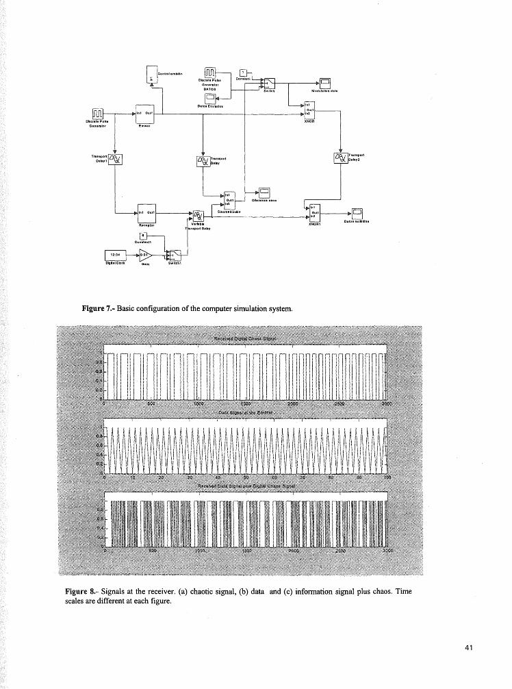
The blocks diagrams corresponding to our computer simulation appears in Fig. 7.
Some more details corresponding to the chaos characteristics have been reported by us in another paper of this Symposium.
¡Figure o.- cnaos syncnronization. channel i minus cnannei z as a mnction oi time is given lor a case wnen syncnromzation is lost at a certain time and by a variation of the time delay is again obtained.
4. DIGITAL MODULATION AND DEMODULATION OF CHAOTIC DIGITAL PORTRAIT The main objective of this paper is to show the possibilities to send and receive digital information from this
system. As it was pointed out before, the main problem concems the way information data are added to the chaotic signal and how the result is sent to the receiver. A direct sum of the signals, as it is usual when one is dealing with analogic signals is not possible now. This is because our data are binary signals, namely "0"s and "l"s and signals with different levels are not allow.
The solution we have adopted is to perform a XNOR function at the emitter, from the chaos and information data. The result is the transmitted signal. At the receiver, this signal is again added, with another XNOR function, with the chaos generated there. The result is the original information signal imposed at the emitter. Results corresponding to a simple case, where the information signal is just an string of alternate "0"s and "1" , appears at Fig. 8. As it can be seen, the recovered signals corresponds with the original one.
Although the reported case is a very straightforward one, it allows us to prove the possibility to send and receive information signals encoded with chaotic signals.
40
m
Rocopla
(M Dberale Pubi
Oonotoloi DATOS
(SI
_^j>__lgvjj DkjUl Clack G . h
—^BJ
l ^ i i
Figure 7.- Basic configuration of the computer simulation system.
*• i.t i
•>*> i)
Í -t, >;•..'.! . " i . : . .•,:.••
Figure 8.- Signals at the receiver, (a) chaotic signal, (b) data and (c) information signal plus chaos. Time scales are different at each figure.

5. CONCLUSIONS The above reported results indicate that a real system with synchronized chaos may be employed as a method to
perform more secure communications. The presented system is a simulation of a real one. Several other factors should be considered in such a case. The first one concerns the problem related to the fact that one or several bits are lost in the way between emitter and receiver. The situation may be crucial if this happens when the synchronizing process in performed. We have not studied how is the robustness of the system and what is the BER (Bit Error Rate) allowed.
Another point is related with the influence of the working characteristics, in a real situation, of employed devices on the chaos generation and synchronization. This problem has been partially analyzed in another paper presented at this Symposium18.
ACKNOWLEDGEMENTS This work has been partly supported by Comunidad Autónoma de Madrid, grant 07T/0017/1997.
REFERENCES
1 V.S. Afraimovich, N.N. Verichev and M.I. Rabinovich, "Stochastic synchronization of oscillations in dissipative systems", Inv. VUZ. Rasiofiz. RPQAEC 29,795-803,1986.
2 L.M. Pécora and T.L. Carroll, "Synchronization in Chaotic Systems", Physical Review Letters 64, 821,1990. 3 L.M. Pécora, "Overview of Chaos and Communications Research", in "Chaos in Communications", SPIE Proceedings,
2038, 2-25, SPIE. Bellingham, WA. 1993. 4 T.L. Carroll and L.M. Pécora, "Synchronizing Chaotic Circuits", IEEE Trans, on Circuits and Systems, 38,453,1991. 5 Several examples are given in "Chua's Circuit: A Paradigm for Chaos". Ed.: R.N. Madan. World Scientific Series on
Nonlinear Science. World Scientific. London. 1993. 6 K.M. Cuomo and A.V. Oppenheim, "Circuit implementation of Synchronized with applications to Communications".
Physical Review Letters, 71, 65-68. 1993 7 K.M. Cuomo, A.V. Oppenheim and S.H. Strogatz, "Synchronization of Lorentz-based Chaotic Circuits with Applications to
Communications". IEEE Trans, on Circ. and Systems. 40. 626-633.1993. 8 T. Stojanovski, L. Kocarev and U. Parlitz, "Digital Coding via Chaotic Systems". IEEE Trans, on Circ. and Systems. 44.
562-565. 1997. 9 J.A. Martín-Pereda and A. González-Marcos, "Digital chaos analysis in optical logic structures". SPIE, 2612, Í70- 180
(1995). 10 A. González-Marcos and J.A. Martín-Pereda, "Digital Chaotic Output from an Optically-Processing Element". Optical
Engineering, 35, pp. 525-535 (1996). 11 A. González-Marcos and J.A. Martín-Pereda: "Sequences of bifurcations and transitions to Chaos in an Optical-Processing
Element". En "Optical computing". Ed.: B.S. Wherrett. pp. 621-624. Inst. Phys. Conf. Series. No. 139 Part IV. 1995. 12 J.A. Martín-Pereda and A. González-Marcos: "Some Connections between Neurophysiology and Optical Computing
based on the Theory of Complexity". En "Fluctuation phenomena: disorder and nonlinarity". Eds.: J. Bishop & L. Vázquez, pp. 107-113. World Scientific Press. Singapore. 1995.
13 J.A. Martín-Pereda and A. González-Marcos, "Digital chaos analysis in optical logic structures". SPIE's Photonics East'95 Symposium. Philadelphia, PA. 22-26 October, 1995. (Paper by invitation).
14 J.A. Martín-Pereda, A. González-Marcos and C. Sánchez-Guillen, "Synchronizing Chaotic Optically-Programmable Digital Circuits". Globecom 96. IEEE Global Telecommunications Conference, Loners. November, 1996.
15 J.A. Martín-Pereda, "Chaos Synchronization in Optically-Programmable Digital Circuits: applications in Communications and Neurophysiology". International Workshop on Nonlinear Optics and Laser Materials". Bilbao. 27-29, Mayo, 1997.
16 A. González-Marcos and J.A. Martín-Pereda, "Digital Chaos Synchronization in Optical Networks". 2nd Working-Conference on "Optical Network Design and Modelling". IFIP.TC6. Rome, Italy. 9 - 1 1 , February, 1998.
17 A. González-Marcos and J.A. Martín-Pereda, "Chaos synchronization in Optically Programmable Logic Cells". International Conference on Applied Photonic Technology, ICAPT'98. Ottawa, Canada. 28-31, Julio, 1998.
18 A. González-Marcos and J.A. Martín-Pereda, "Chaotic behaviour evaluation in optical logic gates with fractal concepts". Photonic Devices and Algorithms for Computing., part of SPIE's International Symposium on Optical Science, Engineering, and Instrumentation. 18-23 July 1999. Denver, CO. Paper 3805-01.
42