transmission lines and e.m. waves prof r.k. shevgaonkar...
TRANSCRIPT

Transmission Lines and E.M. Waves
Prof R.K. Shevgaonkar Department of Electrical Engineering
Indian Institute of Technology Bombay
Lecture-30
Welcome, in the last lecture we investigated the wave
propagation in some arbitrary direction with respect to
the coordinate axis. Our main objective is to find out the
wave propagation in a bound medium and it has been
mentioned earlier that when you are having a bound
medium, the freedom of choosing the coordinate axis is
not really there because choosing the coordinate axis in
a particular direction may simplify the problem at least
algebraically. So normally when we are having the
medium boundaries we choose the coordinate axis so
that it aligns along the boundaries and then the wave
propagates in arbitrary direction with respect to the
coordinate axis because the wave is now incident on the
boundary or some arbitrary angle.
In today’s lecture we will investigate the propagation of
a plane wave at media interface.
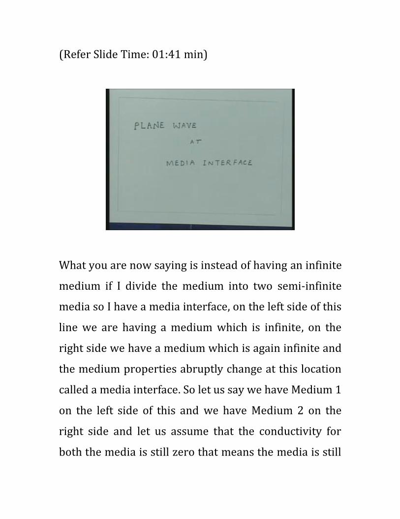
(Refer Slide Time: 01:41 min)
What you are now saying is instead of having an infinite
medium if I divide the medium into two semi-infinite
media so I have a media interface, on the left side of this
line we are having a medium which is infinite, on the
right side we have a medium which is again infinite and
the medium properties abruptly change at this location
called a media interface. So let us say we have Medium 1
on the left side of this and we have Medium 2 on the
right side and let us assume that the conductivity for
both the media is still zero that means the media is still

lossless but the permeability and permittivity are
different for these two media. So let us say the
permeability for this Medium 1 is given by μ1,
permittivity is given by ε1 and for Medium 2 the
permeability is given by μ2 and the permittivity is given
by ε2.
(Refer Slide Time: 02:58 min)
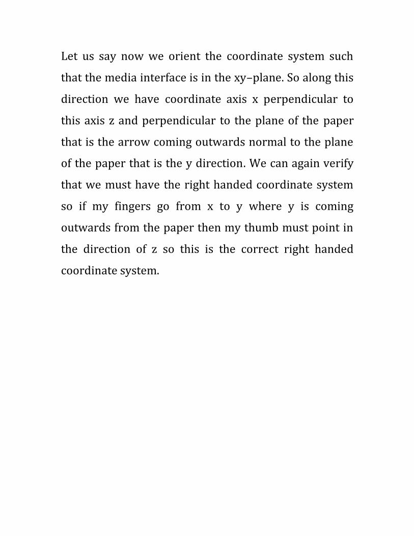
Let us say now we orient the coordinate system such
that the media interface is in the xy–plane. So along this
direction we have coordinate axis x perpendicular to
this axis z and perpendicular to the plane of the paper
that is the arrow coming outwards normal to the plane
of the paper that is the y direction. We can again verify
that we must have the right handed coordinate system
so if my fingers go from x to y where y is coming
outwards from the paper then my thumb must point in
the direction of z so this is the correct right handed
coordinate system.
(Refer Slide Time: 03:45 min)
Now let us say we have a wave which is incident on this
dielectric interface at some arbitrary angle with respect
to the coordinate axis. So I have a wave which is
incident at some arbitrary angle like that, this is the
direction of the wave so essentially this is the wave
vector for the wave which is incident on the dielectric.
Now specifically we are asking questions like when this
uniform plane wave is incident on this dielectric
interface then what will happen to this wave. Intuitively
it appears that part of the energy will get transferred to
the second medium so that will again constitute some
kind of wave propagation but also what is not obvious
at this moment is that part of the energy will get from
the interface, this is what essentially we will argue that
if the wave is incident on this interface we essentially
require two kinds of fields, one which is in the second
medium and also the fields in the first medium all have
to be modified to satisfy the boundary conditions.
So essentially when the wave is incident on the
dielectric interface, part of the energy will be
transferred to the second medium but also the part of
the energy will come back to the first medium and that
is what essentially we will investigate.
When the energy comes back into the first medium or
goes to the second medium what happens to plane wave
nature, which direction the energy will be going are
questions essentially we will have to ask, also we have
to ask for what is the magnitude of the field which goes
to second medium, how much power is going to get
transferred to second medium.
So the analysis of the plane wave at interface essentially
includes finding out the direction in which the waves
will be moving in the two media, how much power get
transferred from one medium to another medium, how
much power comes back from the interface to the first
medium itself, what happens to the direction of the
electric field that means what happens to the
polarization of the electromagnetic wave and so on.
So in this lecture and in the following lectures we will
essentially discuss these issues related to the
propagation of uniform plane wave across a media
interface. And since you have taken conductivity zero
for both these media we can at moment we call this as
Dielectric Media so this is the Dielectric Medium 1, this
is the Dielectric Medium 2. So essentially at the moment
we are investigating propagation of the uniform plane
wave at a dielectric media interface, on both sides we
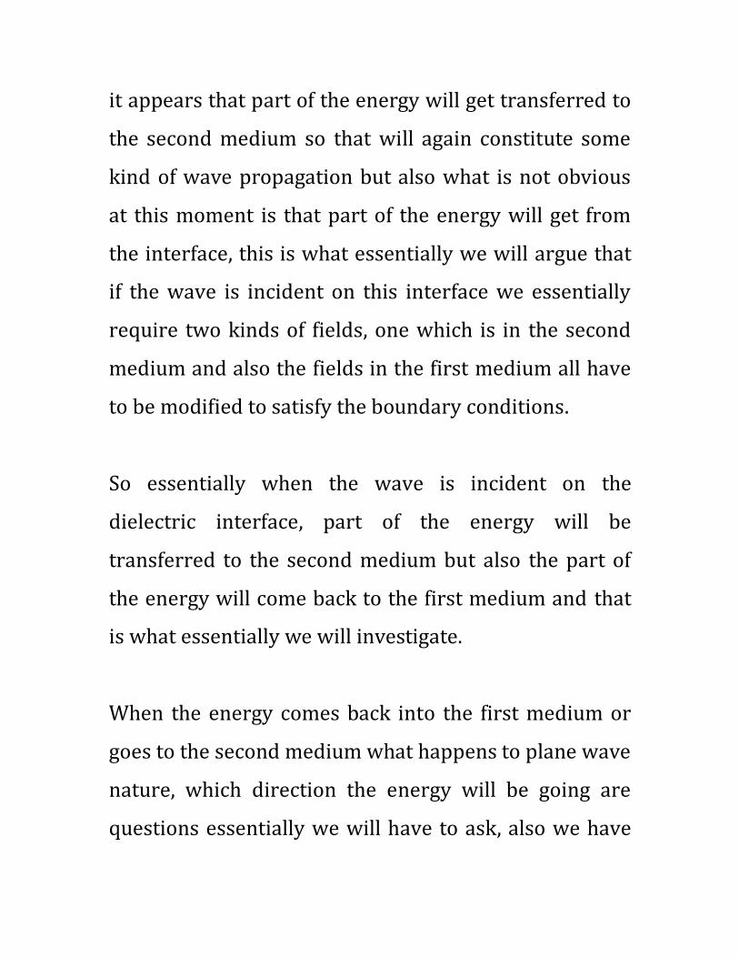
are having media which have dielectrics.
Now let us say this is making an angle with respect to
this direction that this angle is given by some θi.
(Refer Slide Time: 07:00 min)
Now you find certain quantities here that is if I say that
xy-plane is the media interface that means in that plane
suddenly the medium properties change the medium is
uniform in the xy direction only suddenly it changes this
point along this z direction and without losing
generality we can say this quantity z = 0. So let us say
the origin of this coordinate axis at the interface and the
wave vector is making an angle θi with respect to this
direction. Now this z direction is perpendicular to the
media interface so we call this as the normal to the
media interface. So this line the z axis is the normal to
the dielectric media interface.
We are now having a wave traveling at an angle θi with
respect to the normal to the media interface that is the
problem essentially we are having and now you want to
ask when this wave is incident at this angle, what will
happen to this wave. So first of all let us represent this
wave in the form that is the phase function which has
amplitude, let us say without losing generality without
specifically saying we are talking about electric field or
magnetic field you are having some field vector which is
associated with this wave but it has a definite phase
function because it is traveling at an angle θi with
respect to coordinate axis.
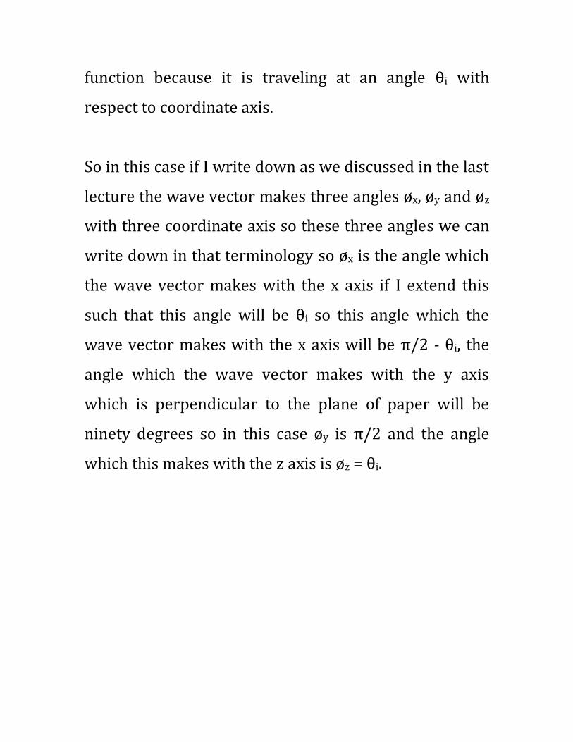
So in this case if I write down as we discussed in the last
lecture the wave vector makes three angles øx, øy and øz
with three coordinate axis so these three angles we can
write down in that terminology so øx is the angle which
the wave vector makes with the x axis if I extend this
such that this angle will be θi so this angle which the
wave vector makes with the x axis will be π/2 - θi, the
angle which the wave vector makes with the y axis
which is perpendicular to the plane of paper will be
ninety degrees so in this case øy is π/2 and the angle
which this makes with the z axis is øz = θi.
(Refer Slide Time: 09:42 min)
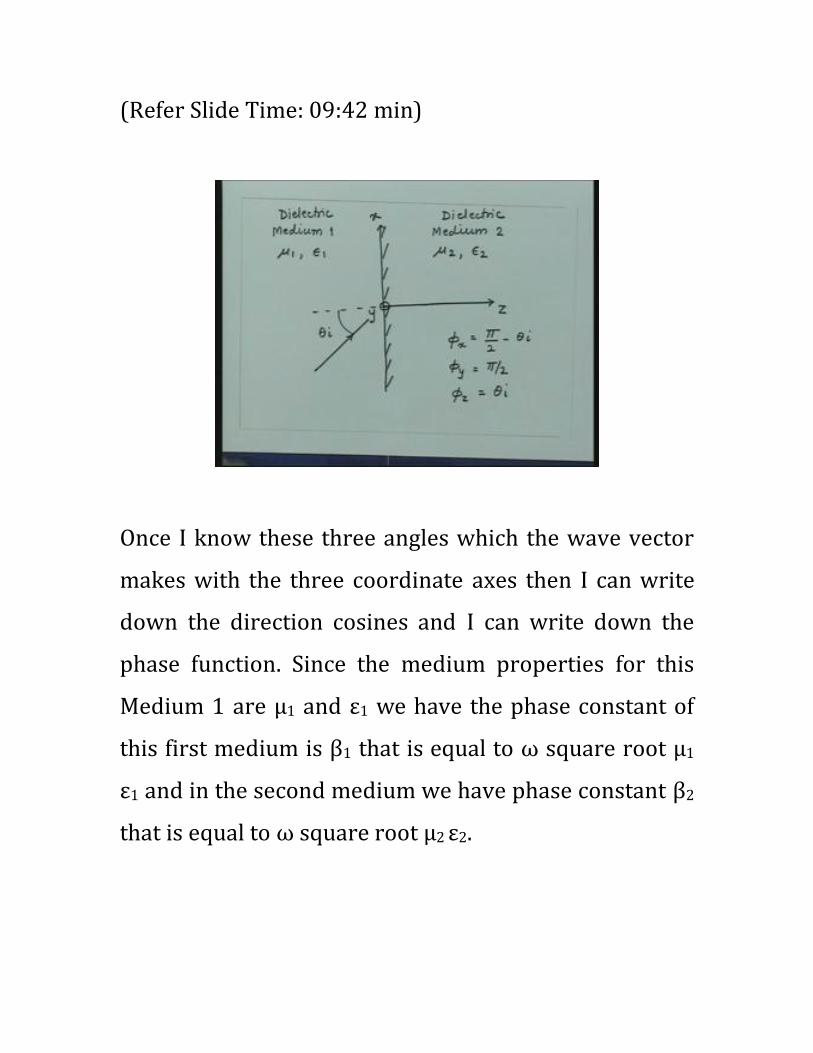
Once I know these three angles which the wave vector
makes with the three coordinate axes then I can write
down the direction cosines and I can write down the
phase function. Since the medium properties for this
Medium 1 are μ1 and ε1 we have the phase constant of
this first medium is β1 that is equal to ω square root μ1
ε1 and in the second medium we have phase constant β2
that is equal to ω square root μ2 ε2.

(Refer Slide Time: 10:22 min)
So I know in both media the phase constant for a plane
wave and we know the angle which the wave vector
makes with the three coordinate axes. So let us say I
have some field represented by this wave which is
having a vector and the phase function will be given as
we saw last time as follows.
Let us say I have some field which is incident and let me
call that as some Fi bar where F could represent the
electric field or magnetic field which is having a

magnitude term so let us say F0i bar which is a vector
and then you are having a phase function which is e to
the power –j since the wave is incident in Medium 1 so
this phase constant is β1 so this is β1 into (cos øx x + cos
øy y + cos øz z).
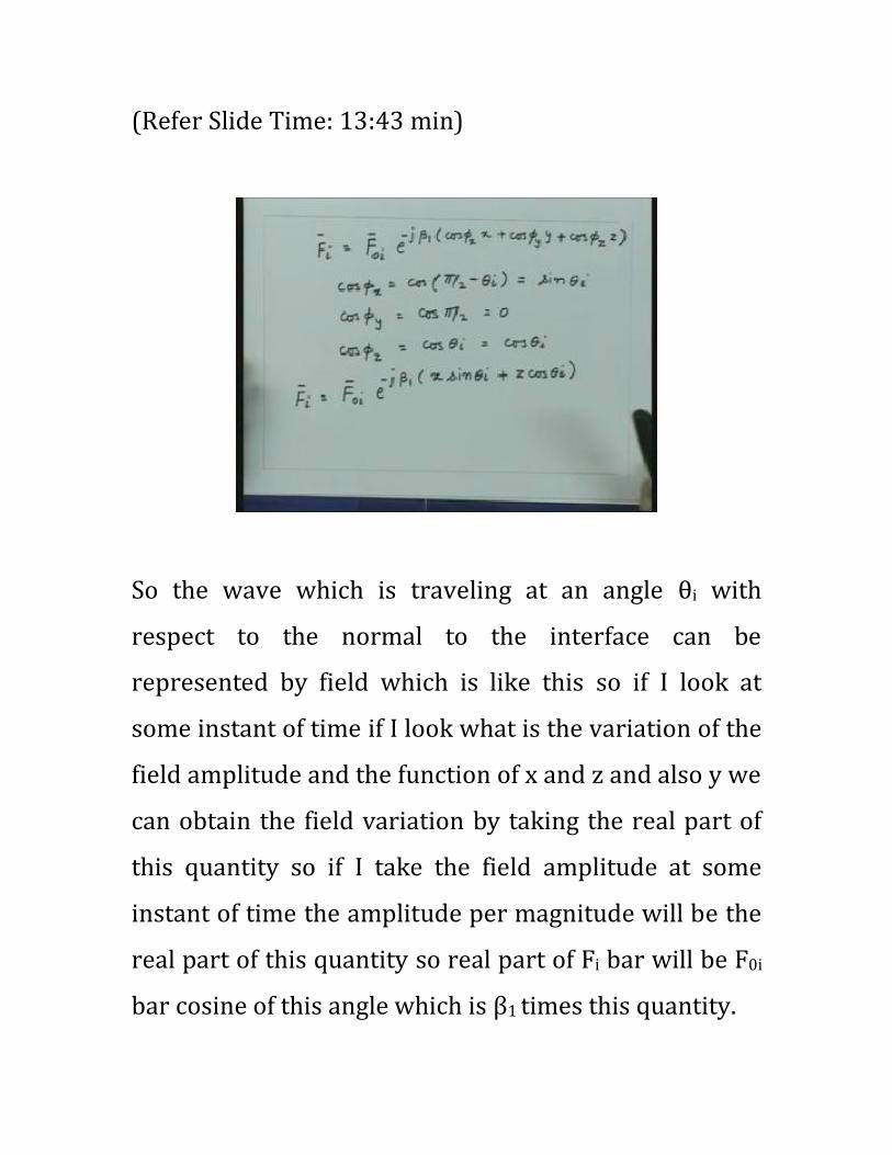
Now since øx is π/2 - θi so cos øx is sin θi, cos øy which is
cos π/2 is zero and cos øz is cos θi. So from here we get
cos øx is cos(π/2 - θi) which is again equal to sin θi, cos
øy = cos π/2 that is zero and cos øz = cos θi that will be
cos θi.
(Refer Slide Time: 12:35 min)
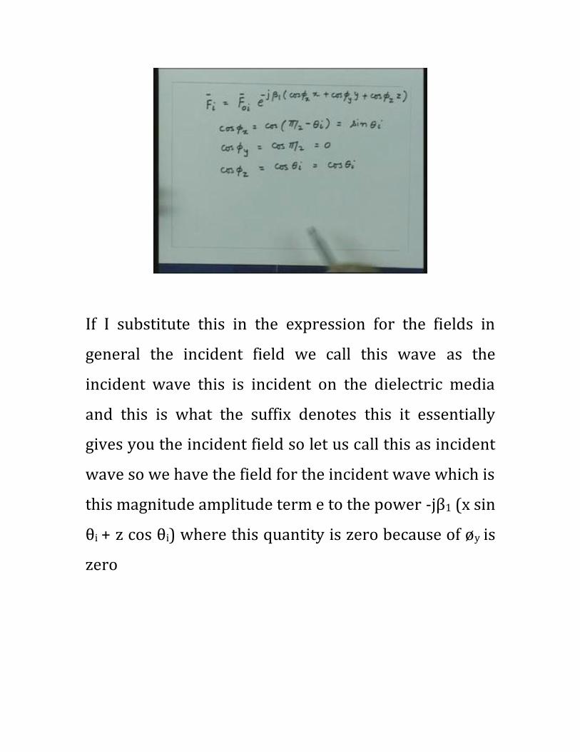
If I substitute this in the expression for the fields in
general the incident field we call this wave as the
incident wave this is incident on the dielectric media
and this is what the suffix denotes this it essentially
gives you the incident field so let us call this as incident
wave so we have the field for the incident wave which is
this magnitude amplitude term e to the power -jβ1 (x sin
θi + z cos θi) where this quantity is zero because of øy is
zero
(Refer Slide Time: 13:43 min)
So the wave which is traveling at an angle θi with
respect to the normal to the interface can be
represented by field which is like this so if I look at
some instant of time if I look what is the variation of the
field amplitude and the function of x and z and also y we
can obtain the field variation by taking the real part of
this quantity so if I take the field amplitude at some
instant of time the amplitude per magnitude will be the
real part of this quantity so real part of Fi bar will be F0i
bar cosine of this angle which is β1 times this quantity.
Let us say I am interested in finding out what is the
variation of the phase in the media interface so I am not
worried about how the phase is varying in z direction
just it has a phase constant which is β1 times F times θi
but at the moment let us say we want to find out what is
the phase variation which I am going to get at the
interface when the wave is incident at this angle since I
have taken the origin z = 0 here then I can substitute z =
0 in this and I get the magnitude of the field in xy-plane
so that will be your F0i cos (β1 x sinθi)
(Refer Slide Time: 15:56 min)

So if I look at the field variation in this xy-plane the field
is having a variation which is cosine variation in the x
direction and it does not have any variation in the y
direction. So essentially this is my media interface if I
plot the field amplitude the field amplitude will vary
like in the x direction and it is constant in the y
direction. So essentially it has created some kind of a
corrugated surface if I want to visualize what this field
variation is, this will be more like a corrugated surface
in this plane where the corrugations are oriented in the
y direction because the direction perpendicular to the
plane of the paper is the y direction. So I got something
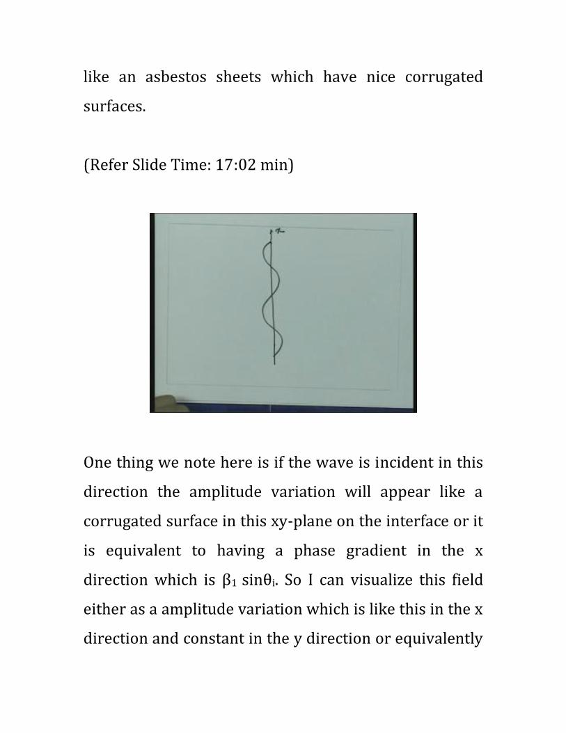
like an asbestos sheets which have nice corrugated
surfaces.
(Refer Slide Time: 17:02 min)
One thing we note here is if the wave is incident in this
direction the amplitude variation will appear like a
corrugated surface in this xy-plane on the interface or it
is equivalent to having a phase gradient in the x
direction which is β1 sinθi. So I can visualize this field
either as a amplitude variation which is like this in the x
direction and constant in the y direction or equivalently
I can say that it is having a phase variation which is β1 x
sinθi or the special gradient of the phase will be β1 sinθi.
So, this one has a phase gradient which is the phase
change per unit length in the x direction will be equal to
-β1 sinθi. If I make θi = 0 then the phase gradient will
become zero so the phase will become constant and that
is what will be the case if the wave is moving
perpendicular to this plane since the wave was coming
perpendicular like this then this θi will be zero and then
this will be constant phase plane so I will not have any
phase gradient in this plane and wave will be traveling
normal to it.
(Refer Slide Time: 18:39 min)

So direction of the wave as it changes introduces a
phase gradient on this plane. So creating a phase
gradient and tilting the direction of the wave are
equivalent that means if the wave direction is changed I
get a phase gradient equivalently, if I create a phase
gradient I will get a wave which will be oriented at
some other direction which will satisfy the phase
gradient. So from here if the phase gradient is given to
you if I equate the phase gradient with -β1 sinθi then I
will get some quantity θi that is the effective direction at
which the wave is traveling.
Now here what we did is we started from the wave
direction and we say this is the phase gradient was
created. But now we can go reverse and say if the phase
gradient was created by some mechanism then
equivalently the wave is traveling at an angle which will
satisfy the phase gradient to be equal to this.
Now in this case the wave was traveling in this direction
as we saw was making an angle θi with respect to this so
if I take a direction like that this was the angle θi. So this
wave which is moving at an angle θi with respect to the
normal has created this phase gradient, alternatively I
can say if I had created this phase gradient it would be
equivalent of having a phase which is coming like this.
Now, if I consider this dielectric interface it will be
immediately clear to you that even if the wave was
incident from this direction exactly at same angle θi
then it also created the same phase gradient but they
are making exactly the same angles with respect to the
normal.
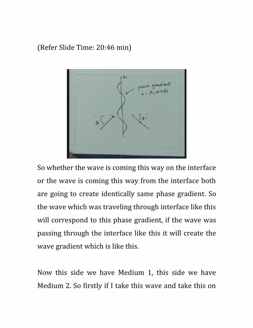
(Refer Slide Time: 20:46 min)
So whether the wave is coming this way on the interface
or the wave is coming this way from the interface both
are going to create identically same phase gradient. So
the wave which was traveling through interface like this
will correspond to this phase gradient, if the wave was
passing through the interface like this it will create the
wave gradient which is like this.
Now this side we have Medium 1, this side we have
Medium 2. So firstly if I take this wave and take this on
this side essentially the same phase gradient
corresponds to the wave which travels away from the
interface at same angle
because this is the phase gradient which corresponds to
this plane in the same direction. So the wave which is
approaching to the interface and wave which is going
away from the interface at the same angle intersect the
normal create the same phase gradient and that is a
very important thing.
But we understand this then we can now ask a question
when the wave was incident on this dielectric interface
what would this wave do? This wave would try to excite
certain fields in this second medium because of the
continuity of the fields.

(Refer Slide Time: 22:15 min)
Now if I want to maintain the continuity of the electric
and the magnetic fields both but once the electric and
magnetic fields are induced into second medium they
see infinite medium ahead of it that means again they
constitute a wave phenomenon and since the medium
seen ahead of them is infinite medium they again see a
transverse electromagnetic behavior for the wave.
Now the wave is in the second medium so the ratio of
the electric field and magnetic field again is decided by
the medium parameter the characteristic impedance or
the intrinsic impedance of the second medium whereas
the electric and magnetic field ratio was decided by the
intrinsic impedance of Medium 1 in this region. So if I
say that the fields are continuous across the boundary
on one side of the ratio of E and H are satisfied by the
intrinsic impedance of this medium and the other side
the E and H are related to the intrinsic impedance of the
second medium. It is immediately clear to me that just
by having the fields on the other side and the original
field which are on this side I cannot satisfy them all
together for both electric and magnetic fields. So what
that means is I have to induce certain fields in the first
medium itself or in other words, we have to modify the
fields in the first medium so that the boundary
conditions can be satisfied for both electric and
magnetic fields at the interface.
So essentially there will be some fields which will be
induced in this medium, there will be some fields which

will be induced in this medium and since the induced
phenomena is due to this phase variation because this is
the one which is created by the incident field both these
fields are induced on two sides are the interface will
have the same phase variation because that is the origin
the induced fields are because of this field which is
incident which is having the phase variation.
So essentially what we note now that the field which
goes into the second medium, the field which get
induced into the first medium also should have a phase
variation which is same as the phase variation because
they are caused because of this and since this phase
variation is uniform in this direction these fields must
also constitute a phenomenon for which the field is
constant in this direction and I mentioned since this
fields are time varying fields, again they will constitute a
wave phenomena so the induced field in this medium
will constitute a wave phenomena, fields in this medium
again will constitute a wave phenomena and these fields
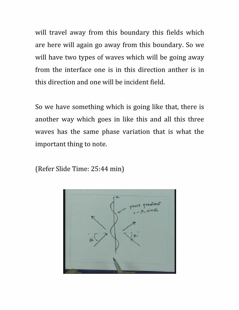
will travel away from this boundary this fields which
are here will again go away from this boundary. So we
will have two types of waves which will be going away
from the interface one is in this direction anther is in
this direction and one will be incident field.
So we have something which is going like that, there is
another way which goes in like this and all this three
waves has the same phase variation that is what the
important thing to note.
(Refer Slide Time: 25:44 min)
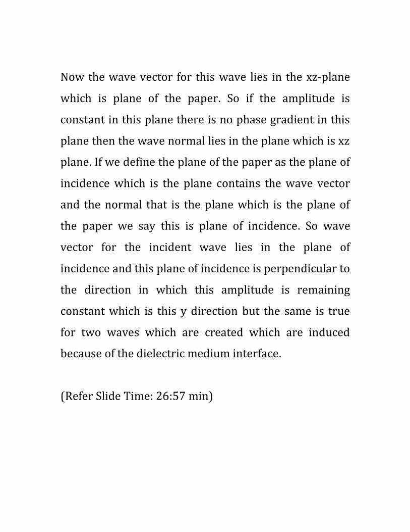
Now the wave vector for this wave lies in the xz-plane
which is plane of the paper. So if the amplitude is
constant in this plane there is no phase gradient in this
plane then the wave normal lies in the plane which is xz
plane. If we define the plane of the paper as the plane of
incidence which is the plane contains the wave vector
and the normal that is the plane which is the plane of
the paper we say this is plane of incidence. So wave
vector for the incident wave lies in the plane of
incidence and this plane of incidence is perpendicular to
the direction in which this amplitude is remaining
constant which is this y direction but the same is true
for two waves which are created which are induced
because of the dielectric medium interface.
(Refer Slide Time: 26:57 min)
So you are having a uniform variation for this field also
that means the wave vector corresponding to these two
waves also must lie in this plane which is the plane of
incidence. So what we conclude is make a very
important conclusion that the wave vector for the
incident wave for this wave induces which is in second
medium and the wave vector which is going to first
medium all three lie in the same plane then that plane is
the plane of incidence. As we mentioned this wave
incidence is going away from this interface, this will
carry some energy so we will say what ever energy
came to the interface part of the energy was reflected
from the interface and part of the energy was
transmitted.
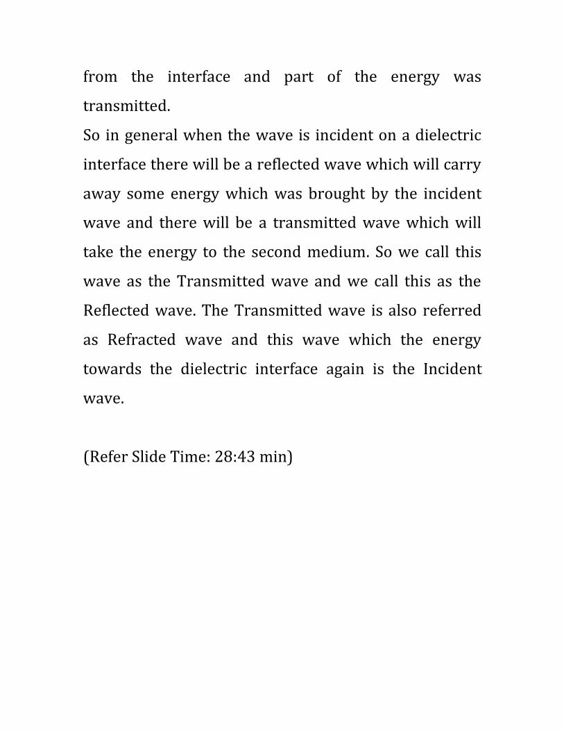
So in general when the wave is incident on a dielectric
interface there will be a reflected wave which will carry
away some energy which was brought by the incident
wave and there will be a transmitted wave which will
take the energy to the second medium. So we call this
wave as the Transmitted wave and we call this as the
Reflected wave. The Transmitted wave is also referred
as Refracted wave and this wave which the energy
towards the dielectric interface again is the Incident
wave.
(Refer Slide Time: 28:43 min)
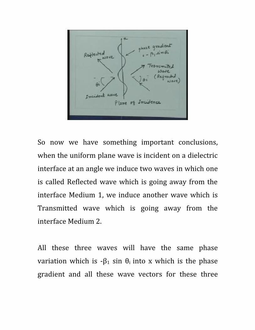
So now we have something important conclusions,
when the uniform plane wave is incident on a dielectric
interface at an angle we induce two waves in which one
is called Reflected wave which is going away from the
interface Medium 1, we induce another wave which is
Transmitted wave which is going away from the
interface Medium 2.
All these three waves will have the same phase
variation which is -β1 sin θi into x which is the phase
gradient and all these wave vectors for these three
waves lie in the same plane that is the plane of
incidence.
Now if you recall the light is a transverse
electromagnetic wave and in the high school we had
studied the laws of reflection for light and the first law
of reflection was the incident ray, the reflected ray and
the refracted ray lie in the same plane which is the
plane of incidence. So essentially the statement the first
law of reflection comes from matching this phase
condition on the interface and that says that these three
vectors lie in the same plane.
Now the wave vector in optics is referred to as the
direction of the ray so this is the ray in which the light is
moving. However, we call the direction as the wave
vector as we go to general Electromagnetics. So we are
having a general statement called the first law of
reflection that is the wave vector for incident,
transmitted and reflected wave lie in the same plane of

incidence and the plane of incidence is the plane which
contains the wave vector and the normal to the
interface. So we got the first law of reflection
established by this condition.
Now the next thing is that when the waves are moving
in this direction, in what direction the wave would be
moving with respect to normal? Since this angle is θi
and this medium is same the phase gradient what ever I
have if I divide that quantity by β1 and take sin inverse
of that then that would give me the direction of the
wave propagation in that particular medium. So the
direction at which the wave moves is if I know the
phase gradient the first phase gradient what ever is
created if I divided that by the phase constant of that
medium then sine of the angle at which the wave travels
is given by that quantity.
So from here I can write the phase gradient divided by
the phase constant, the angle which the wave makes

with normal is θ that is nothing but sine inverse of the
phase gradient divided by the phase constant. So
somebody has given me the phase gradient then I can
take the phase gradient divided by the phase constant in
that medium take the sine inverse of that quantity and
that essentially gives me the direction of the wave
motion in that medium.
So in this case in Medium 1, let us say this angle at
which the reflected wave goes is denoted by θr the angle
of reflection and let us say the wave goes is given by θt
which we call as theta transmission angle so we have a
situation where the incident wave is at a angle θi with
respect to normal the reflected angle is at a angle θr
with respect to normal and the transmitted wave is the
angle θt with respect to normal.
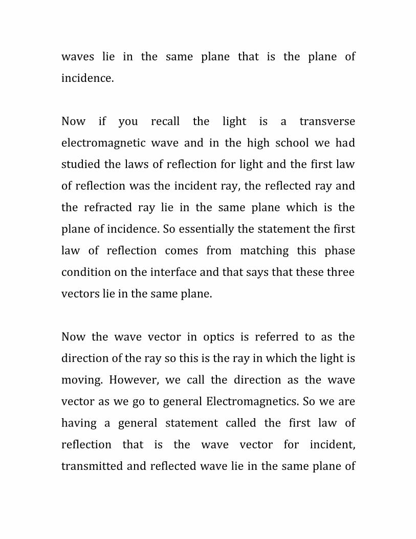
(Refer Slide Time: 33:28 min)
Now we are having a situation with one wave is like that
let us say this is my normal this is the angle θi
something goes at some other angle this is my reflected
wave let us say this angle is θr at some other angle I call
this as transmitted wave let us say this angle is θt. This
is incident wave, this is reflected wave and this is
transmitted wave. And I am having a phase gradient on
this surface which is -β1 sinθi. I put a minus sign here.
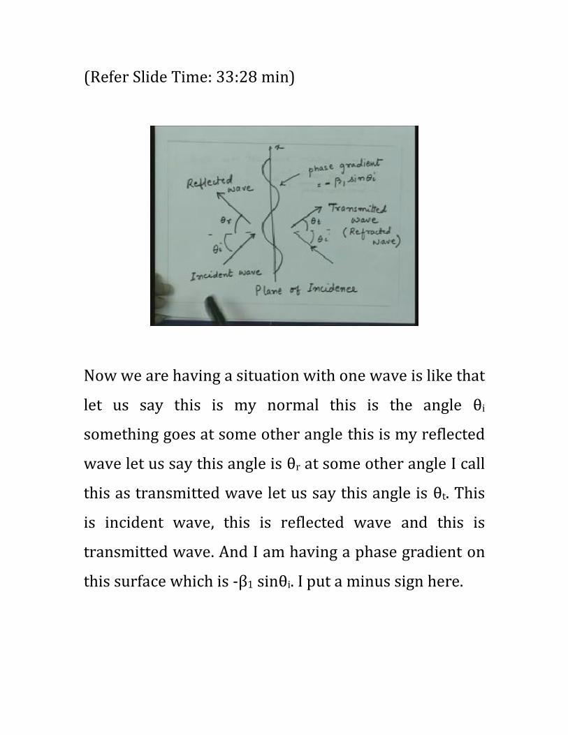
(Refer Slide Time: 34:28 min)
So what I can do is if I see in Medium 1 I can substitute
this phase gradient value and sine inverse of that
quantity or sine of this angle will be equal to the minus
of phase gradient divided by the phase constant.
Now the phase constant is β1 in this medium and the
phase constant is β2 in this medium. So sinθr should be
minus of phase gradient divided by the phase constant,
from here I get sinθr that is equal to minus times the
phase gradient which is β1 sinθi divided by phase
constant which is β1. So this is minus times minus β1
sinθi divided by the phase constant in the Medium 1
which is β1 so this is equal to sinθi.
So this implies θr is equal to θi. This is your second law
of reflection that the angle of incidence is equal to angle
of reflection. So what ever angle the wave is incident at
the same angle with respect to normal the ray will be
reflected or the wave vectors will be making same angle
with respect to the normal. This will be going towards
the interface this will be going away from the interface
but these two angles are equal. So we see another
important conclusion from matching of the phase angle
that these two angles are equal. This is in medium one
which was for the reflected wave.
The same thing we can do for the second medium and
that is if I go to Medium 2 then the angle which this
thing makes is θt so sinθt should be equal to minus of
phase gradient divided by the phase constant but the

phase constant in this medium is β1 so from here we get
sinθt is equal to minus of minus β1sinθi divided by β2
because now we are having Medium 2. So from here
essentially I get, β1 sinθi is equal to β2 sinθt.
(Refer Slide Time: 37:43 min)
And we know β1 and β2 in medium in which β1 is nothing
but ω square root μ1ε1 and β2 is ω square root μ2ε2 so if I
substitute in this, this will be ω square root of μ1ε1 sinθi
that is equal to ω square root of μ2ε2 sinθt.
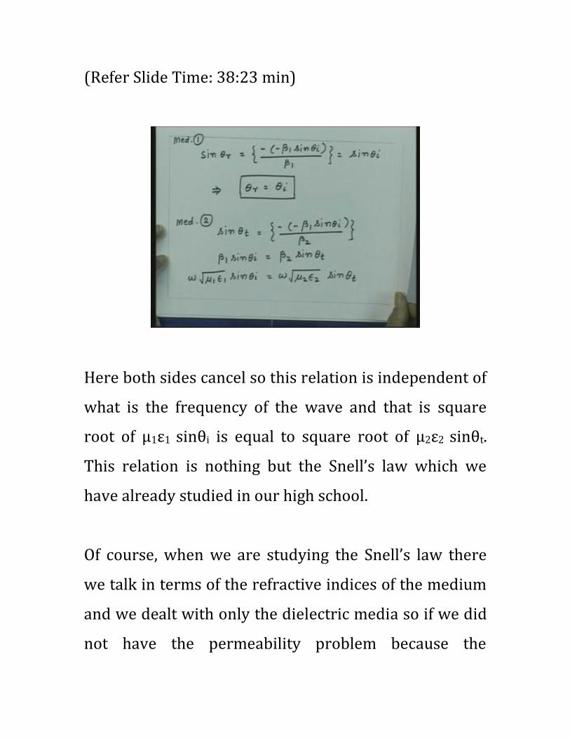
(Refer Slide Time: 38:23 min)
Here both sides cancel so this relation is independent of
what is the frequency of the wave and that is square
root of μ1ε1 sinθi is equal to square root of μ2ε2 sinθt.
This relation is nothing but the Snell’s law which we
have already studied in our high school.
Of course, when we are studying the Snell’s law there
we talk in terms of the refractive indices of the medium
and we dealt with only the dielectric media so if we did
not have the permeability problem because the
materials were not magnetic. So we talked only in terms
of refractive indices and we can see from here how do
we get the special case that when the media are only
dielectrics and the permeability of the medium is same
on both sides. The relation essentially reduces to the
relation in terms of the refractive indices.
But this is the important law which tells you the
direction of the transmitted wave with respect to the
direction of the incident wave for the given media
parameter. So we can call this as the generalized Snell’s
law.
(Refer Slide Time: 39:58 min)
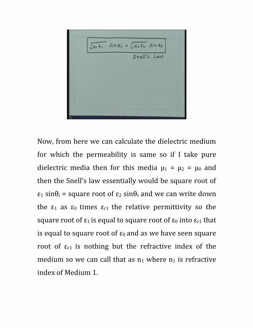
Now, from here we can calculate the dielectric medium
for which the permeability is same so if I take pure
dielectric media then for this media μ1 = μ2 = μ0 and
then the Snell’s law essentially would be square root of
ε1 sinθi = square root of ε2 sinθt and we can write down
the ε1 as ε0 times εr1 the relative permittivity so the
square root of ε1 is equal to square root of ε0 into εr1 that
is equal to square root of ε0 and as we have seen square
root of εr1 is nothing but the refractive index of the
medium so we can call that as n1 where n1 is refractive
index of Medium 1.

Similarly we can have square root of ε2 is equal to
square root ε0 εr2 that is equal to square root of ε0 into
n2 where n2 is refractive index of medium two.
(Refer Slide Time: 42:06 min)
So if I substitute this in your generalized Snell’s law
then this square root of epsilon cancels on both sides so
I will get finally a relation which will be n1 sinθi = n2
sinθt or the way we write the Snell’s law sinθt will be n
one upon n1/n2 sinθi.

This is the law you are familiar with because we have
already studied this law in optics in our high school
physics that if a light ray is incident at an angle θi and
the refractive indices of the media are given by n1 and
n2 then the transmitted or the refracted angle which is
θt that will be related by this. So this was a special case
of the Snell’s law for dielectrics.
In fact when we studied this law in high school physics
they appear like these laws came from nowhere.
However, this law essentially comes from the wave
nature of the light and since light is a transverse
electromagnetic wave when it is incident on a dielectric
interface it has to satisfy certain phase conditions and
from the phase condition we establish these laws of
reflection and refraction.
So let me summarize what we did we started with a
wave propagation in some arbitrary direction then we
said if the wave is propagating in some arbitrary

direction it creates a phase gradient on the media
interface this phase gradient is same for the wave which
is induced on two sides of the media which we call the
transmitted wave and reflected wave and then we
found that changing the direction of the wave and
creating the phase gradient are essentially equivalent so
if I change the direction of the wave I get a phase
gradient conversely if I create a phase gradient I get a
change the direction of the wave.
So what we find here is that the fields which are
induced have the same phase gradients which are
created on the interface and from there essentially we
can find out the directions in which the waves will be
traveling. So we found this relation that the direction of
the wave propagation is we can find out from here that
is the angle of the wave which it makes with the normal
will be minus times the phase gradient divided by the
phase constant in that medium sine inverse of that gives
me the angle with which finally the wave will be

traveling at that medium. Using this nature essentially
we establish the laws of reflection and also the Snell’s
law which gives the relationship between the incident
and the transmitted wave.
Once you understand this then the analysis of wave
propagation across the dielectric media is quite straight
forward. The idea here is that you write down the phase
function for both the media for all the three waves
match the boundary conditions at the interface and then
find out the amplitude of electric and magnetic fields in
this media for these two wave with respect to the
incident wave.
So let us see if I have a incident wave having an
amplitude which is Fi of a electric field with is Ei or
magnetic field Hi. Then we want to find out what are the
relative amplitudes of the electric and magnetic fields
for the reflected wave and for the transmitted wave.
So let us say we have a wave which will be having
electric and magnetic fields. now the problem
essentially we want to investigate is, there is a wave
which is incident on this we know this is going to be
reflected at same angle part of the thing this angle now
is θi and this angle also is now theta θi because θr = θi
and this angle is theta θt. This is the incident wave so let
us say this one had a electric field which is given by Ei
bar, say I take electric field for this is given by Er bar and
I take the electric field which is given by Et bar.
So we have a magnitude for the electric field. These are
not directions for electric fields these are the wave
vectors electric field will be oriented in some direction
which will be perpendicular to the wave vector. But if
you have the amplitude of these three fields which are
given by Ei, Er and Et we want to find out what is the
relationship between these two so what is the ratio of
this and this and that quantity we call as a transmission

coefficient for this interface and the ratio of E0 and Ei we
call as the reflection coefficient for this interface.
(Refer Slide Time: 48:20 min)
So we again have the quantities which are we are
familiar in some sense because we have seen the
reflection coefficient in case of transmission line that is
when ever we are having impedance mismatch then the
part of the energy is reflected.
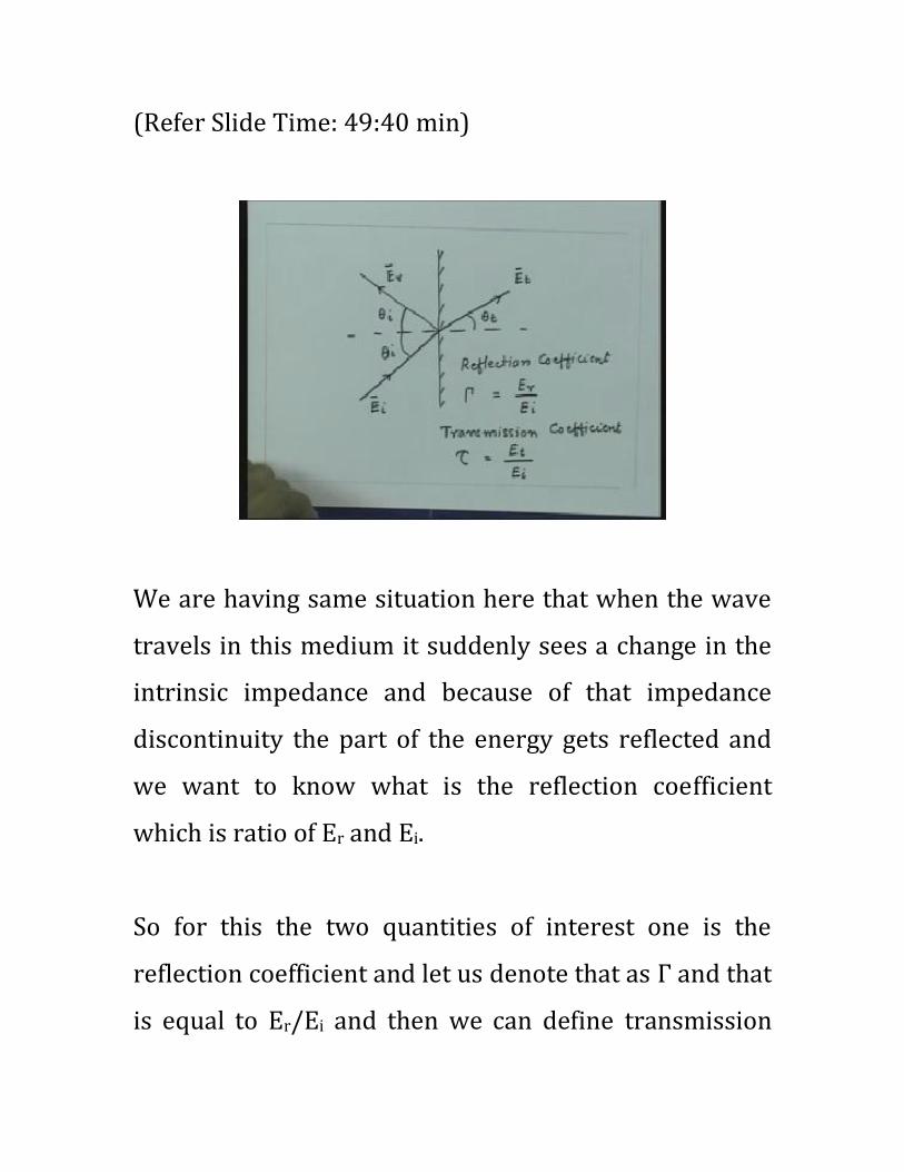
(Refer Slide Time: 49:40 min)
We are having same situation here that when the wave
travels in this medium it suddenly sees a change in the
intrinsic impedance and because of that impedance
discontinuity the part of the energy gets reflected and
we want to know what is the reflection coefficient
which is ratio of Er and Ei.
So for this the two quantities of interest one is the
reflection coefficient and let us denote that as Г and that
is equal to Er/Ei and then we can define transmission
coefficient generally this is denoted by τ and that is
equal to Et/Ei. Since we are defining this coefficient for
the electric field we can specifically call them as the
electric field reflection coefficient and electric field
transmission coefficient the similar quantities you can
define for magnetic field also but we know since the
electric and magnetic fields are related to each other by
the intrinsic impedance of the medium, if we know this
quantity is electric field in the three media then we can
find out appropriately the magnetic fields also.
The important thing to note here is that the wave which
was incident on this was the transverse electromagnetic
wave so the ratio of E and H was equal to intrinsic
impedance in this medium, the ratio of the electric and
magnetic field for this wave is also intrinsic impedance
of this medium for this again a traverse electromagnetic
wave and this wave is again a traverse electromagnetic
wave so the ratio for the electric and magnetic field for
this medium is also intrinsic impedance. So if I say the
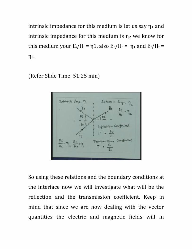
intrinsic impedance for this medium is let us say η1 and
intrinsic impedance for this medium is η2 we know for
this medium your Ei/Hi = η1, also Er/Hr = η1 and Et/Ht =
η2.
(Refer Slide Time: 51:25 min)
So using these relations and the boundary conditions at
the interface now we will investigate what will be the
reflection and the transmission coefficient. Keep in
mind that since we are now dealing with the vector
quantities the electric and magnetic fields will in
general make an arbitrary angle with respect to this
plane so you may have electric field which might be
oriented at some angle like this. So normally what we
do, we decompose the problem into taking the
component of the electric field in the direction
perpendicular to the plane and a direction which is in
the plane.
So essentially what we do is any electric field we
decompose into two cases or any general case we
decompose into two what we call as the parallel
polarization where electric field lies in the plane of
incidence and a perpendicular polarization where
electric field lies perpendicular to the plane of
incidence. So we have to find out these quantities for
these two cases for parallel polarization and
perpendicular polarization and once we get that then
we can get the total characteristic of the wave which is
polarized at an arbitrary angle with respect to the plane
of incidence.

So, in the next lecture essentially we will take these two
cases specifically the parallel and perpendicular
polarization and then investigate their reflection and
transmission properties across the dielectric media.
Thank you.