transmission lines and e. m. waves prof. r. k. shevgaonkar...
TRANSCRIPT

Transmission Lines and E. M. Waves
Prof. R. K. Shevgaonkar
Department of Electrical Engineering
Indian Institute of Technology, Bombay
Lecture – 59
Problems on Waveguides
In this session we solve few problems related to the waveguides. So we will take two
problems which are based on parallel plane waveguide and then we will take two
problems which are based on the rectangular waveguide.
(Refer Slide Time: 2:04)
Let us consider a problem here that in a parallel plate waveguide the phase velocity of TE
3 mode is 1.4c where c is that velocity of light. Find the guided wavelength of TM 2
mode inside the waveguide. The waveguide has been filled with a material having
dielectric constant of 9 and the frequency of the wave is 1 Gigahertz. So in this case we
are given the velocity of TE 3 mode and as we know the velocity is related to the size of
the wave guide. We can find out from this information what is the size of the waveguide
and once we know size of the waveguide then we can find out the phase velocity for any
other mode so in this case for TM 2 mode and once we know the phase velocity and the

frequency then we can find out the guided wavelength for this mode which is TM 2
mode.
So as we know the phase velocity for any mode v p is given as omega by beta where beta
is the the phase constant in the direction of wave propagation inside the waveguide and
that is equal to the velocity of light in the medium which is filling the waveguide divided
by root 1 minus m lambda divided by 2 d whole square where lambda is the wavelength
and v is the velocity filling the medium. So this velocity in this case since the waveguide
is filled with air this v is c so we have essentially the information of this velocity which is
1.4c and then we have the information which is this one which is c.
(Refer Slide Time: 4:00)
So now if I substitute these quantities into this relation, first of all this velocity now, since
the dielectric constant of the material which is filling the waveguide is 9 this velocity v
will be equal to the velocity of light c divided by square root of epsilon r which is 9 so
that is equal to c upon 3. Then by inverting this relation we can get this quantity here
which is m lambda upon 2 d that will be equal to square root of 1 minus v divided by v p
that is equal to square root of 1 minus c upon 3 this velocity divided by 1.4c. Solving this
essentially we get this quantity here and in this case this velocity is given for the mode

which is TE 3 mode so m is equal to 3; so for TE 3 mode m is equal to 3 so we can
substitute here so we get 3 lambda upon 2 d that is equal to square root of this quantity
which is 1 minus 1 upon 4.2 that will be equal to 0.58.
(Refer Slide Time: 5:56)
So, from here we can find out this quantity lambda upon d so we get lambda upon d that
is equal to 2 into 0.58 upon 3. Now once we know this quantity lambda upon d then we
can find out the phase velocity for TM 2 mode. So the phase velocity for TM 2 mode is
the v p will be equal to v divided by square root of 1 minus... since now in this case m is
equal to 2 so this will be 2 upon lambda upon 2 d whole square. So we can substitute for
this lambda upon d into this expression from here so this is 2 will cancel so this will be
equal to the v divided by square root of 1 minus this quantity which is 1.16 divided by 3
whole square and v is nothing but the velocity of light in that medium which is filling the
waveguide so this is nothing but c by 3 so this is equal to c by 3 which is c is 3 into 10 to
the power 8 meters per second so this quantity v here (Refer Slide Time: 7:49) is equal to
3 into 10 to the power 8 divided by 3 that is equal to 10 to the power 8 meters per second.
So substituting here for v we get 10 power 8 divided by this quantity 1 minus 1.16 upon 3
whole square that is that will be equal to 1.229 into 10 to the power 8 meters per second.

Once we know this velocity phase velocity and the frequency then we can find out the
guided wavelength of this. So lambda g for this will be equal to v p divided by the
frequency which is 1 Gigahertz so 1 Gigahertz so this is equal to 1.229 into 10 to the
power 8 divided by 1 Gigahertz which is 10 to the power 9 so that gives us 0.122 meters.
(Refer Slide Time: 9:03)
So in this problem the characteristics for a particular mode are given which is TE 3 mode
and we are asked to find out the properties or the characteristic for TM 2 mode. And
since these are related through the size of the waveguide and the frequency, essentially
we can find out from here the the characteristics of TM 2 mode after getting the
dimension of the waveguide, that is what precisely we have done in this.
Let us consider another problem which is again a problem on parallel plane waveguide.
But this waveguide now is divided into two parts. So essentially we are having here
parallel planes which are given like this and half the waveguide is filled with one
dielectric material and half the waveguide is left empty.

(Refer Slide Time: 9:56)
So the problem here is as follows: in the following waveguide find the frequency at
which the TE 1 mode does not have any reflection at the waveguide junction at z equal to
0. So we have here parallel plane waveguide, this is z equal to 0, so, for z less than 0 the
waveguide is filled with a material with the dielectric constant 4 and relative permeability
10 and for z greater than 0 the dielectric constant is 1 and the relative permeability is 1
and the width of the waveguide or height of the waveguide is equal to 10 centimeter.
So now you have to find out the frequency for which there will not be any reflection from
from here. What that means is essentially that we have a traveling wave which is coming
here in TE 1 mode and since there is no reflection... in this region also we have only
forward traveling wave, in this region also we have only forward traveling wave so the
problem essentially can be solved by matching the boundary condition at z equal to 0 for
the mode which is in this region for z less than 0 and for the region which is z greater
than 0.
So first we get the the fields for TE 1 mode and essentially made the boundary
conditions. Now as we know for TE 1 mode we get the field components which will be
the y component which will be like this the y direction is coming out of the paper so we

have the y component for the electric field and for the magnetic field will have a z
component and the x component. So, for matching the boundary condition then the y
component which is this it should be continuous across the boundary and also since we
have normal component of the magnetic field that should be continuous so we can
essentially apply the continuity of the z component of magnetic field and the y
component of the electric field for the mode.
So, at z equal to 0 we have got E y 1 is equal to E y 2 and H z 1 is equal to H z 2. Now
the nodal fields will have different phase constants in z direction because now the
medium which is filling the waveguide is different for z less than 0 and greater than 0 so
let us say that the phase constant in this is given by beta z 1 and the phase constant in this
is given by beta z 2.
(Refer Slide Time: 12:58)
This is the phase constant for TE 1 mode in this region and in this region, let us call this
as 1 (Refer Slide Time: 13:10), this region is 1 and this is 2. So now we can write down
the field expressions here. So we know the the field expression if I write down at z equal
to 0 we will get this which corresponds to some E 01 sin of pi x upon d that will be equal

to E 02 sin of pi x upon d which essentially will give that the amplitude of these two E 01
is equal to E 02 that you get from the continuity of the y component.
(Refer Slide Time: 13:59)
For the z component as we know this is E 01 upon eta 1 beta z 1 upon beta 1 where beta 1
is the phase constant in a medium which is filling this waveguide for z equal to z less
than 0. So, if I take a medium which is of infinite extent and whose dielectric constant is
4 and relative permeability is 10 then beta 1 will be the phase constant of uniform plane
wave in that medium; that multiplied by sin of pi x by d that will be equal to E 02 upon
eta 2 beta z 2 upon beta 2 sin of pi x by d.
So this equation (Refer Slide Time: 15:06) we are getting from here, this is this comes
from here and this equation is coming from the magnetic fields from here. So, from the
first equation we have got E 01 equal to E 02 so this will this will cancel and this sin pi x
by d that is again common on both sides so we get from this boundary condition beta z 1
upon eta 1 beta 1 that is equal to beta z 2 upon eta 2 beta 2.

(Refer Slide Time: 15:30)
Now we can write down for beta 1 and eta 1, so from here we get by substituting the
medium parameters we get beta 1 eta 1 equal to omega square root mu 0 mu r 1 epsilon 0
epsilon r 1 into eta 1 which is square root of mu 0 mu r 1 divided by epsilon 0 epsilon r so
we get from here this will be omega mu 0 mu r 1. Similarly, we can calculate this
quantity here which is beta 2 eta 2 that will be... since this medium (Refer Slide Time:
17:04) the relative permittivity is 1 relative permeability is 1 essentially this quantity if
we substitute mu r equal to 1 epsilon r equal to 1 we will get beta 2 eta 2 that will be
nothing but omega mu 0.
So substituting now for these two in these expression essentially we get omega mu 0 beta
z 1 is equal to omega mu 0 mu r 1 beta z 2; again mu 0 omega will cancel, these two and
this quantity now we can write down in terms of the phase constant of the medium beta 1
and the phase constant of the medium beta 2. So from here we can get square root of beta
1 square minus pi upon d whole square.
In general we have here m pi upon d but since we are talking about a mode which is TE 1
mode that is what it is incident on this (Refer Slide Time: 18:22) so you put m equal to 1
that will be equal to mu r 1 square root of beta 2 square minus pi upon d whole square.

(Refer Slide Time: 18:45)
Keep in mind we are essentially assuming here; keep in mind that the TE 1 mode which
is coming here and on this side also only the TE 1 mode propagates. It is possibly general
that many other modes might propagate in this region. However, we are saying that since
the field variation in this has to be identical to the field variation which is going to get
excited in this for matching the boundary condition continuity of the electric field the
field distribution in this region must be identical in the transverse direction to the field
distribution in a region 1 in region 1 and that is the reason we are saying that the mode
which is going to propagate at this will also be TE 1 mode and that is why the index for
this also will be equal to 1.
once we once we get that then we can simplify these expressions and we get from here
beta 1 square minus pi upon d whole square that is equal to mu r 1 square into beta 2o
square minus pi upon d whole square. So from here we can get beta 1 square minus mu r
1 square beta 2 square that will be equal to pi upon d whole square into mu r 1 square
minus 1 with a minus sign.
Now noting that this quantity here beta 1 is equal to omega square mu 1 epsilon 1 that is
omega square mu 0 mu r 1 epsilon 0 epsilon r 1 and beta 2 square is equal to omega

square mu 0 epsilon 0. We can substitute into this expression here and from here we can
find out this quantity omega which will be equal to pi upon d square root of 1 minus mu r
1 square upon mu 0 mu r 1 epsilon 0 epsilon r 1 minus mu r 1. So this is the frequency at
which we have a continuity of the field and therefore we will not have any reflection
from from this boundary here which is at z equal to 0 (Refer Slide Time: 22:16).
So even if the medium properties inside the waveguide suddenly change from these
parameters to free space still there will not be any reflection from this continuity and
wave will be launched inside this waveguide without any reflection.
(Refer Slide Time: 22:30)
So this is the frequency at which essentially the wave can be launched without any
reflection even if we are having a medium discontinuity inside the waveguide.
Substituting now for these parameters mu r 1 equal to equal to 10 epsilon r 1 equal to 4,
all that we can solve for the frequency so this omega will be 2pi into frequency, so we
can calculate from here the frequency that will be equal to 1.927 Gigahertz.
In fact as we have seen for parallel plane waveguide analysis that the modal propagation
can also be seen as the reflection of the uniform plane wave on this conducting planes so

we can we can visualize this TE 1 mode as if the plane wave is going like that (Refer
Slide Time: 23:31), reflected between these two plane and we have a sustained
propagation, then we know that this plane wave essentially is going to see this dielectric
boundary and we know that there is no reflection for the for a uniform plane wave from a
dielectric boundary when the wave is launched at the Brewster angle.
So for this if I can visualize this TE 1 mode as superposition of the uniform plane waves
then I can find out an angle at which the wave is incident at the Brewster angle at this
interface and then from there I can calculate the frequency for which we will we will get
no reflection on the boundary.
(Refer Slide Time: 24:11)
So this problem can be solved in fact in two ways: one is taking the fields for a particular
mode and then matching the boundary conditions at z equal to 0. Second way is that
visualizing this TE 1 field by superposition of uniform plane waves and then applying the
concept of Brewster angle; and both the methods are acceptable and both the methods
essentially give the same value.

Let us now consider a problem which is based on rectangular waveguide. Let us consider
a rectangular waveguide of cross section 4 centimeter into 3 centimeter cross section and
that carries the dominant mode and as we know the dominant mode of a waveguide is TE
10 mode the frequency of the mode is 6 Gigahertz. The maximum peak electric field
measured inside the waveguide is 50 volts per meter. Find the expression for the electric
and magnetic fields inside the waveguide and the power carried out by the waveguide.
(Refer Slide Time: 25:02)
So first we have to find out the field expressions. Once we know the field expressions
then we can find out what is the poynting vector, once we get the pointing vector we can
integrate the pointing vector over the cross section of the waveguide and then we can get
the total power guided by the waveguide.
So problem essentially, first is to find out the fields given the condition that the maximum
electric field is 50 volts per meter and then find out the pointing vector and then the
power carried by the mode.
So in this problem the waveguide is a rectangular waveguide. So a in this case is 4
centimeter, for writing in meters this is 0.04 meters and b for this is 0.03 meters and the

mode which is the dominant mode of the waveguide that is TE 10 mode. So for this mode
waveguide h the parameter which we have defined for the waveguide that is nothing but
pi upon a so this is equal to pi upon 0.04. Once we know this then we can find out what is
the phase constant for this mode on this waveguide, so that is beta that will be equal to
square root of omega square mu epsilon minus pi upon a whole square.
The waveguide is filled with air, nothing has been given about what material is filling the
waveguide so we assume that waveguide is filled with air so the relative permeability and
relative permittivity for the media for this medium filling the waveguide are unity and the
frequency is 6 Gigahertz. So we can write here omega will be equal to 2pi into 6
Gigahertz so 6 into 10 to the power 9 radians per second; mu is equal to mu 0 which is
equal to 4pi into 10 to the power minus 7 Henry per meter and epsilon will be equal to
epsilon 0 which is 1 upon 36pi into 10 to the power minus 9 Farad per meter and pi upon
a is given here.
(Refer Slide Time: 28:17)
So if I substitute all these values inside in this expression we get the phase constant for
this mode beta that is equal to 98.09 radians per meter.

Now if I look at the expression which are given for the TE 01 mode inside this
waveguide we have got the expressions that H z is equal to d where d is some constant
cos of pi x upon a E y that is equal to minus j omega mu divided by pi upon a d into sin
of pi upon a into sin of pi x by a and H x is equal to j beta upon pi upon a d into pi upon a
sin of pi x upon a and the other field components for TE 10 mode are 0.
(Refer Slide Time: 30:01)
So now what we see here that this is the constant in terms of which we had derived all the
field components. So E y was in terms of d, E x was in terms of d; however, now this
parameter d is not given, what is given is the maximum electric field the peak electric
field which we can measure inside the waveguide is 50 volts per meter. That means this
quantity (Refer Slide Time: 30:32) which is a coefficient of this that quantity is 50 volts
per meter.
So essentially what this will cancel so what that essentially means is that the peak electric
field that is equal to omega mu into d that is equal to 50 volts per meter. Since I know the
frequency, I know the permeability which is free space permeability, I can find out the
value of d which is 50 divided by omega mu so this is 50 divided by 2pi into 10 to the

power 9 into 6 so 6 Gigahertz multiplied by 4pi into 10 to the power minus 7 that will be
equal to 1.055 into 10 to the power minus 3.
(Refer Slide Time: 31:56)
So once I get the value of d then I can substitute into these expressions and I can find out
the the field components so I get now the field components E y that is equal to minus j 50
sin of pi x upon 0.04, H x will be equal to j 0.1035 sin of pi x upon 0.04 and H z will be
equal to 1.055 into 10 to the power minus 3 cos of pi x upon 0.04. So I substituted the
value of d in these three expressions (Refer Slide Time: 33:00). In fact from here this is
the magnetic field so that dimension of d should be amperes per meter.

(Refer Slide Time: 33:18)
So this is now the fields which we get for this waveguide for the dominant mode and
once we know this field then we can write down the Poynting vector. So we have got
Poynting vector p that is equal to 1/2 for real part of E cross H conjugate so this one H z
and E y they will not have any real part because this is having j this is nothing but j so the
product of these two will give the power which will be imaginary so this essentially
would be equal to 1/2 into E y into H x so this is 50 into 0.1035 into sin square pi x upon
a.
Once I know this Poynting vector then I can find out the total power guided by the
waveguide w that will be equal to the integrated poynting vector over the cross section so
x will be 0 to a y equal to 0 to b Poynting vector dx dy. So I can substitute for P inside
this and put a and b you will get the total power carried by the waveguide w that will be if
you if you solve this you will get 2.588 so it is 2.588. The Poynting vector does not vary
in y direction (Refer Slide Time: 35:30) so this integral with respect to y will simply b so
that will be equal to b integral 0 to a sin square pi x upon a into dx.
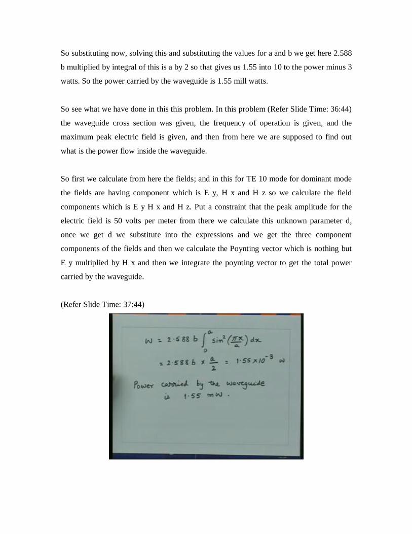
So substituting now, solving this and substituting the values for a and b we get here 2.588
b multiplied by integral of this is a by 2 so that gives us 1.55 into 10 to the power minus 3
watts. So the power carried by the waveguide is 1.55 mill watts.
So see what we have done in this this problem. In this problem (Refer Slide Time: 36:44)
the waveguide cross section was given, the frequency of operation is given, and the
maximum peak electric field is given, and then from here we are supposed to find out
what is the power flow inside the waveguide.
So first we calculate from here the fields; and in this for TE 10 mode for dominant mode
the fields are having component which is E y, H x and H z so we calculate the field
components which is E y H x and H z. Put a constraint that the peak amplitude for the
electric field is 50 volts per meter from there we calculate this unknown parameter d,
once we get d we substitute into the expressions and we get the three component
components of the fields and then we calculate the Poynting vector which is nothing but
E y multiplied by H x and then we integrate the poynting vector to get the total power
carried by the waveguide.
(Refer Slide Time: 37:44)

(Refer Slide Time: 37:58)
Let us take one more problem here that is a rectangular waveguide made of copper has 4
centimeter into 7 centimeter cross section. The waveguide is filled with a material with
dielectric constant 3 and this dielectric material is lossy so it has a loss tangent of 10 to
the power minus 5. Determine all the modes which will propagate at 3 Gigahertz. What is
the total attenuation of the waveguide in dbs per meter for the dominant mode? The
conductivity of copper is 5.88 into 10 to the power 7 mhos per meter.
So in this case there are three things we have to find out. First: we have to find out all the
modes which will propagate inside the waveguide at 3 Gigahertz. Second: the attenuation
constant of the waveguide which will come from two components one is because of lossy
dielectric because it has a loss tangent of 10 to the power minus 5 and the finite
conductivity of the walls because here the conductivity is not infinite so there will be
conductor losses in the waveguide walls. So we have to calculate the attenuation constant
for the dominant mode of the waveguide.
So let us see how do we proceed for this. Firstly, to find out how many modes will
propagate at a given frequency we essentially find out the cutoff frequency and then we
find then if the cutoff frequency is less than the frequency of operation then the mode will

propagate, if the cutoff frequency is higher than 3 Gigahertz then the mode will not
propagate.
So we know for a rectangular waveguide the cutoff frequency f of c that is equal to 1
upon 2pi square root mu 0 epsilon 0 epsilon r; here the dielectric material we are talking
about so the relative permeability is equal to 1. Also, since the loss tangent is very small
for calculation of cutoff frequency we consider the dielectric constant almost real and that
is equal to 3 so the epsilon r is equal to 3 multiplied by m pi by a whole square plus n pi
by b whole square the power 1/2. That is the expression for the cutoff frequency and we
know this quantity one upon square root mu 0 epsilon 0 is nothing but the velocity of
light in vacuum so 1 upon square root mu 0 epsilon 0 is equal to 3 into 10 to the power 8
meters per second. Substituting this we get f of c the cutoff frequency of a mode that is
this to be this divided by 2 will give me 1.5 into 10 to the power 8 divided by square root
of epsilon r, this square root of 3, this m pi (Refer Slide Time: 41:35) will cancel with this
pi so this will give m upon a which is for this waveguide which is 7 centimeter and b is 4
centimeter so this will be 0.07 whole square plus n upon 0.04 whole square square root.
(Refer Slide Time: 42:00)

So, simplifying this we get simply 1.5 into 10 to the power 8 divided by root 3 into 100
into m upon 7 whole square plus n upon 4 whole square square root this should be 100
square here. So from here essentially we get the condition for m and n.
(Refer Slide Time: 42:55)
So if m square upon 49 plus n square upon 16, if the frequency f c is less than the
frequency which is 3 Gigahertz then the mode will propagate. So what that means is if
this this quantity here where substitute here for the frequency then we get that if this
quantity (Refer Slide Time: 43:32) is less than 3 upon 25 then the modes will propagate.
So now we can try for different values of m and n and as we know m and n both are
integers so we can start with all possible combinations of m and n for which this
condition is satisfied. So we can take m is equal to 1 and equal to 0, we can take m equal
to 0 n equal to 1, we can take m equal to 1, n equal to 1, we can take m equal to 2, n equal
to 0 and beyond this this condition will not be satisfied so essentially we got the modes
which would be corresponding to TE or TM with the indices for m which is going from
0, 1, 2 and the second index which is going from 0 and 1.

Now as we know, for TE case one of the indices nonzero will still give me the mode
whereas for the transverse magnetic case both the indices have to be nonzero so the
modes which will propagate inside the waveguide are corresponding to this you have TE
10, then you have TE 01, then you have TE 11 but for both the indices non zero even the
TM mode will be existing so you have got TM 11 and then here again we will get TE 20.
So at 3 Gigahertz inside this waveguide these five modes will propagate: TE 10, TE 01,
TE 11, TM 11 and TE 20.
(Refer Slide Time: 45:46)
The second part which is asked in this problem is to find now the attenuation constant for
the dominant mode and that is the TE 10 mode.
Since the loss is coming from two components: one is dielectric loss, other one is the
conductor loss and since the losses are small what we do is we calculate these losses one
at a time and then we calculate total attenuation constant which will be the sum of the
two attenuation constants.

So first we calculate beta for the TE 10 mode and that is square root of omega square mu
0 epsilon 0 epsilon r minus pi upon a whole square. If I substitute the values for epsilon r
which is 3 and a which is the dimension of the waveguide that is 7 centimeter so it is 0.07
I get the propagation constant which is 99.14 radians per meter.
Now the attenuation constant due to dielectric loss as we have derived alpha d that is
equal to omega square mu epsilon 0 upon 2 beta into tangent of delta tan delta I can
substitute here which is 2pi into frequency square and this quantity here mu mu into
epsilon 0 that will be 1 upon velocity square so this will be 3 into 10 to the power 8
square into 2 beta into two 2 into tan delta which is 10 to the power minus 5 that is what
is given here that the medium has a loss tangent of 10 to the power minus 5.
So I can substitute these values for all this and then I can solve for alpha d which will be
equal to 5.94 into 10 to the power minus 3 Nepers per meter.
(Refer Slide Time: 48:36)
Then we can calculate the conductor loss; the attenuation constant due to the finite
conductivity of the walls and that as we know is given as the surface resistance into 1
plus 2 b upon a f c upon f whole square divided by eta b square root of 1 minus f c upon f

whole square and f c we know as the cutoff frequency for the TE 10 mode which is
nothing but 1 upon 2 a square root mu epsilon and in this case it is mu 0 epsilon 0 so that
will be equal to 1.237 Gigahertz and the surface resistance is square root of omega mu
upon 2 sigma so I can substitute the value of the conductivity per copper which is 5.88 10
to the power 7, I know the frequency which is 3 Gigahertz so I can calculate this quantity
which is a surface impedance; I can substitute into this so we have all the parameters we
know the cutoff frequency, we know the frequency of operation, we know the dimension
of the waveguide a and b, we know the surface impedance and we know the eta which is
the intrinsic impedance which is 120pi for the free space.
(Refer Slide Time: 50:24)
So, by substituting these values essentially we can calculate this quantity alpha c which is
equal to 0.438 into 10 to the power minus 3 nepers per meter.
Then since the losses are small, the total attenuation constant alpha is approximately
equal to alpha d plus alpha c and that is that will be equal to the attenuation because of
dielectric which is 5.94 so 5.94 into 10 to the power minus 3 plus 0.438 into 10 to the
power minus 3 nepers per meter so we can add these and we find out the total attenuation
constant for this waveguide.

(Refer Slide Time: 51:41)
Then this attenuation constant now is the nepers per meter. So if I multiply this quantity
by 8.68 I will get the attenuation constant in dbs per meter. So essentially see what we
have done in this problem.
Firstly though you were asked to find out how many modes will propagate inside this
waveguide. So we so at a given frequency thus the dimension of the waveguide or given
the dielectric constant of the medium the waveguide is given and we are asked to find out
how many modes will propagate. So first you find out the cutoff frequency for modes,
then you find out a condition for m and n for which the cutoff frequency will be less than
the frequency of operation which is 3 Gigahertz so we get this condition, from here
(Refer Slide Time: 52:28) then we find out what are the indices which can satisfy this
condition and then by using the knowledge that TE modes can exist given when one of
the indices is not zero whereas for TM mode both the indices have to be nonzero we find
these modes which can propagate inside this waveguide.
from here then we calculate the... for TE 10 we can calculate the phase constant, then by
using the expression which we have derived we find out the attenuation constant due to
dielectric and then we find out the attenuation constant due to the finite conductivity of

the waveguide walls and the sum of the two essentially gives the total attenuation
constant.
So these are some of the representative examples which you will see for the waveguide.
Typically the waveguide dimensions are given, the frequency of operation is given and
we have to find out the modal characteristics of the waveguide, that is how many modes
will propagate; and also we have problems where we have a dominant mode which is
propagating on the waveguide and then we would be interested in finding out how much
power will flow, what will be field expressions for that mode, what be the Poynting
vector, what will be loss and so on.
So these once we see these problems then on the similar lines other problems related to
the waveguide also will be solved very easily.