transmission grid code - lewa.org.ls grid code ... 7.8 transmission line protection requirements ......
TRANSCRIPT

LESOTHO GRID CODE
Page 1 of 109
TRANSMISSION GRID CODE
DRAFT DOCUMENT
March 2012
LESOTHO GRID CODE
Page 2 of 109
LESOTHO GRID CODE
TABLE OF CONTENTSTRANSMISSION GRID CODE .............................................................................................................................................1
DRAFT DOCUMENT..........................................................................................................................................................1
PREAMBLE .............................................................................................................................................................................9
PURPOSE OF GRID CODE..................................................................................................................................................9
OBJECTIVE OF THE GRID CODE ...................................................................................................................................10
DEFINITIONS ........................................................................................................................................................................11
SECTION 1 .............................................................................................................................................................................26
GOVERNANCE OF THE CODE ........................................................................................................................................26
1.1 Introduction............................................................................................................................................................26
1.2 Objective .................................................................................................................................................................26
1.3 Responsibilities ....................................................................................................................................................26
1.4 Grid Code Review Panel .....................................................................................................................................26
1.5 Standing Committees to deal with specific issues..................................................................................27
1.6 Grid Code Review Panel Rules .....................................................................................................................27
1.7 Functions of the Grid Code Review Panel .................................................................................................28
1.8 Grid Code Review and Revisions Procedures..........................................................................................28
1.9 .Disputes.................................................................................................................................................................29
1.9.1. Dispute pertaining to issues not covered by the Grid Code ................................................................29
1.9.2 Continuity of Functioning of Grid Users ...................................................................................................29
1.9.3 Unforeseen Circumstances ..........................................................................................................................29
SECTION 2.............................................................................................................................................................................30
GRID CONNECTION CODE ................................................................................................................................................30
2.1 Introduction ..............................................................................................................................................................30
2.1.1 Purpose ..............................................................................................................................................................30
2.1.2 Scope of Grid Connection Requirements ..................................................................................................30
2.2 Grid Technical, Design and Operational Criteria .............................................................................................31
2.2.1 Power Quality Standards................................................................................................................................31
2.2.2 Frequency Variation .....................................................................................................................................31
2.2.3 Voltage Variations.........................................................................................................................................31
2.2.4 Harmonics .......................................................................................................................................................31
2.2.5 Voltage Unbalance........................................................................................................................................31

LESOTHO GRID CODE
Page 3 of 109
2.2.6 Voltage Fluctuation and Flicker Severity................................................................................................32
2.2.7 Transient Voltage Variations......................................................................................................................32
2.2.8 Grounding Requirements ............................................................................................................................32
2.2.9 Equipment Standards...................................................................................................................................32
2.3 Requirements for Grid Connection or Modification .....................................................................................32
2.3.1 Connection Agreement...............................................................................................................................32
2.3.2 Amended Connection Agreement ............................................................................................................32
2.3.3 Grid Impact Studies......................................................................................................................................33
2.3.4 Procedures for Application for Connection or Modification .............................................................33
2.3.5 Processing of Application ..........................................................................................................................34
2.3.6 Submittals Prior to the Commissioning Date ........................................................................................34
2.3.7 Commissioning of Equipment and Physical Connection to the Grid .............................................35
2.4 Requirements For Large Generators................................................................................................................35
2.4.1 Requirements Relating to the Connection Point..................................................................................35
2.4.2 Generating Unit Power Output ..................................................................................................................36
2.4.3 Frequency Withstand Capability...............................................................................................................36
2.4.4 Unbalance Loading Withstand Capability ..............................................................................................36
2.4.5 Speed- Governing System..........................................................................................................................36
2.4.6 Excitation Control System..........................................................................................................................37
2.4.8 Fast Start Capability .....................................................................................................................................37
2.4.9 Protection Arrangements ...........................................................................................................................38
2.4.10 Transformer Connection and Grounding ..............................................................................................38
2.5 REQUIREMENTS FOR DISTRIBUTORS AND OTHER GRID USERS ..........................................................39
2.5.1 Requirements Relating to the Connection Point ....................................................................................39
2.5.2 Protection Arrangements ............................................................................................................................39
2.5.3 Transformer Connection and Grounding.................................................................................................39
2.5.4 Underfrequency Relays for Automatic Load Shedding .....................................................................39
2.6 COMMUNICATION AND SCADA EQUIPMENT REQUIREMENTS................................................................40
2.6.1 Communication System for Monitoring and Control ..........................................................................40
2.6.2 SCADA System for Monitoring and Control ..........................................................................................40
2.7 FIXED ASSET BOUNDARY DOCUMENT REQUIREMENTS .........................................................................41
2.7.1 Fixed Asset Boundary Document.............................................................................................................41
2.7.2 Accountable Managers................................................................................................................................41
2.7.3 Preparation of Fixed Asset Boundary Document ................................................................................42
2.7.4 Signing and Distribution of Fixed Asset Boundary Document ........................................................42
2.7.5 Modifications of an Existing Fixed Asset Boundary Document ......................................................42
2.8 ELECTRICAL DIAGRAM REQUIREMENTS .....................................................................................................43
2.8.1 Responsibilities of TSO and Users ..........................................................................................................43

LESOTHO GRID CODE
Page 4 of 109
2.8.2 Preparation of Electrical Diagrams ..........................................................................................................43
2.8.3 Changes to Electrical Diagrams ...............................................................................................................44
2.8.4 Validity of Electrical Diagrams ..................................................................................................................44
2.9 CONNECTION POINT DRAWING REQUIREMENTS.......................................................................................44
2.9.1 Responsibilities of TSO and Users..........................................................................................................44
2.9.2 Preparation of Connection Point Drawings ...........................................................................................45
2.9.3 Changes to Connection Point Drawings ................................................................................................45
2.9.4 Validity of the Connection Point Drawings ............................................................................................46
2.10 GRID DATA REGISTRATION ..............................................................................................................................46
2.10.1 Data to be Registered...............................................................................................................................46
2.10.2 Stages of Data Registration....................................................................................................................46
2.11 Data Forms .............................................................................................................................................................47
2.12 Connected Plant Restrictions............................................................................................................................47
2.12.1 General Principle.........................................................................................................................................47
2.12.2 Safety .............................................................................................................................................................48
2.12.3 Insulation ......................................................................................................................................................48
2.12.4 Clearances....................................................................................................................................................48
2.12.5 Earthing ..........................................................................................................................................................48
2.12.6 Safety Training .............................................................................................................................................48
2.12.7 Access by TSO .............................................................................................................................................49
2.12.8 Unintended and Unscheduled back- energisation ..............................................................................49
2.12.9 Site And Equipment Identification ........................................................................................................49
SECTION 3 .............................................................................................................................................................................50
PERFORMANCE STANDARDS CODE ...........................................................................................................................50
3 POWER QUALITY STANDARDS .................................................................................................................................50
3.1 Introduction ..............................................................................................................................................................50
3.3 Power Quality ........................................................................................................................................................50
3.3.1 Frequency Variations .................................................................................................................................50
3.3.2 Harmonics .......................................................................................................................................................51
3.3.3 Voltage Variations .........................................................................................................................................52
3.3.4 Voltage Unbalance ........................................................................................................................................52
3.3.5 Voltage Fluctuation and Flicker Severity .................................................................................................53
3.4 Reliability Standards ............................................................................................................................................54
3.4.1 Service Reliability ..........................................................................................................................................54
3.5 Power Factor .........................................................................................................................................................54
3.5.1 General description ....................................................................................................................................54
3.5.2 Reactive Power Requirements ...................................................................................................................55
SECTION 4.............................................................................................................................................................................55
LESOTHO GRID CODE
Page 5 of 109
TRANSMISSION PLANNING CODE ..................................................................................................................................55
4.2 TRANSMISSION SYSTEM PLANNING CRITERIA...........................................................................................56
4.2.1 Voltage Levels ..................................................................................................................................................56
4.2.2 Normal Operation ............................................................................................................................................56
4.2.3 Outage Conditions............................................................................................................................................57
4.2.4 Other Criteria ..................................................................................................................................................59
4.3 NETWORK DEVELOPMENT APPROACH AND METHODOLOGY ........................................................61
4.3.1 Objectives .....................................................................................................................................................61
4.3.2 Approach ......................................................................................................................................................61
4.3.3 Methodology ................................................................................................................................................62
4.3.4 Transmission Planning Tools ......................................................................................................................66
4.4 POWER GENERATION DEVELOPMENT PLAN ............................................................................................66
4.4.1 Planning Approach ....................................................................................................................................67
4.5.2 Demand Side Management (DSM) ............................................................................................................69
4.5.3 Options Available .......................................................................................................................................69
4.5.4 Operating Environment...............................................................................................................................69
4.6 PLANNING DATA EXCHANGE ...........................................................................................................................70
SECTION 5.............................................................................................................................................................................71
TRANSMISSION OPERATIONS CODE .............................................................................................................................71
5.1 Introduction....................................................................................................................................................................71
5.2 Purpose ...................................................................................................................................................................71
5.3 Responsibility....................................................................................................................................................71
5.4 System Monitoring...............................................................................................................................................73
5.5 System Services......................................................................................................................................................73
5.5.1 Frequency Control Service ...........................................................................................................................73
5.5.2 Voltage Control Service ................................................................................................................................74
5.5.3 Equipment loading........................................................................................................................................75
5.6 Operational Planning .......................................................................................................................................76
5.6.1 Demand and Supply planning ...................................................................................................................76
5.6.2 Outage Planning..........................................................................................................................................76
5.6.3 Contingency Planning .................................................................................................................................77
5.7 Data and Records Storage ...........................................................................................................................77
5.7.1 Demand and Energy Data............................................................................................................................77
5.7.2 Safety records ..............................................................................................................................................78
5.7.3 Fault Recording And Reporting ................................................................................................................78
5.8 Safety Coordination .............................................................................................................................................79
5.8.1 Responsibility...................................................................................................................................................79
5.8.2 Authorised Persons ...................................................................................................................................79

LESOTHO GRID CODE
Page 6 of 109
5.8.3 Work On Plant and Equipment .....................................................................................................................79
5.8.4 Accidents During Work .............................................................................................................................80
5.9 Communications ..................................................................................................................................................80
5.10 Demand Control ................................................................................................................................................80
5.10.1 Planned Demand Control........................................................................................................................80
5.10.2 Emergency Automatic Demand Control ..................................................................................................81
5.11 Power System Restoration After Blackout ................................................................................................81
5.12 Network Switching ...........................................................................................................................................82
SECTION 6 .............................................................................................................................................................................83
TRANSMISSION METERING CODE ..................................................................................................................................83
6.1 Introduction ...............................................................................................................................................................83
6.2 Objective .................................................................................................................................................................83
6.3 Scope .......................................................................................................................................................................83
6.4 Metering Equipment ............................................................................................................................................83
6.5 Billing Meters .......................................................................................................................................................84
6.6 Integrating Pulse Meters ....................................................................................................................................84
6.7 Responsibility For Metering Installations......................................................................................................84
6.8 Metering Equipment Standards...........................................................................................................................85
6.8.1 Voltage Transformers ..................................................................................................................................85
6.8.2 Current Transformers ..................................................................................................................................85
6.8.3 Meters...............................................................................................................................................................86
6.8.4 Integrating Pulse Recorders ......................................................................................................................86
6.9 System Monitoring...............................................................................................................................................87
6.9.1 Instrument Transformer Testing ................................................................................................................87
6.10. Meter Testing and Calibration ....................................................................................................................88
6.10.1 Request for Test ..........................................................................................................................................88
6.11.1 Maintenance of Metering Equipment ......................................................................................................88
6.11.2 Metering Equipment Security ...................................................................................................................88
6.12 Meter Reading and Metering Data ....................................................................................................................88
6.12.1 Integrating Pulse Metering Data ...............................................................................................................88
6.12.2 Running Total of Active Energy and Power ..........................................................................................89
6.12.3 Running Total of Reactive Energy and Power ......................................................................................89
6.12.4 Billing and Settlement Procedure ............................................................................................................89
6.13 Settlement Audit Procedure ...............................................................................................................................90
6.13.1 Right to Request Settlement Audit ..........................................................................................................90
6.13.2 Allocation of Audit Cost ............................................................................................................................90
6.13.3 Audit Results................................................................................................................................................90
6.13.4 Audit Appeals...............................................................................................................................................90

LESOTHO GRID CODE
Page 7 of 109
6.14 Confidentiality ........................................................................................................................................................90
SECTION 7 .............................................................................................................................................................................91
TRANSMISSION PROTECTION CODE .............................................................................................................................91
7.1 Introduction ...........................................................................................................................................................91
7.2 Objective ................................................................................................................................................................91
7.3 General Principles .................................................................................................................................................91
7.4 Protection Coordination at the Connection Point .........................................................................................92
7.5 Testing of Protection Equipment .......................................................................................................................92
7.6 Fault Clearance Times .........................................................................................................................................92
7.7 Generator Protection Requirements ................................................................................................................92
7.8 Transmission Line Protection Requirements .................................................................................................93
7.8.1 Transmission Line Protection Design Standard ..................................................................................93
7.8.2 Automatic Re closing (ARC) On Transmission Lines .........................................................................93
7.8.3 Power Swing Blocking.................................................................................................................................94
7.11 Transformer Protection Requirements: ..........................................................................................................94
7.12 Sub- Station Bus Bar Protection.......................................................................................................................94
7.13 Teleprotection Requirements ............................................................................................................................94
7.13.1 Introduction ..................................................................................................................................................94
7.13.3 Teleprotection Schemes............................................................................................................................95
7.14 Overvoltage Protection.........................................................................................................................................95
7.14.1 Protection against Lightning Over voltages...........................................................................................96
7.15 Protection Against Switching Surges at the Connection Point ................................................................96
7.16 Protection of Compensating Equipment ........................................................................................................96
7.16.1 Protection of Reactors ...............................................................................................................................96
7.16.2 Protection of Capacitors ...........................................................................................................................97
7.16.3 Protection of Static Var Compensators .................................................................................................97
7.17 Under frequency Load Shedding......................................................................................................................97
7.18 Safety Protection Requirements .......................................................................................................................97
7.18.1 Fire Protection............................................................................................................................................97
7.18.2 Personnel Protection................................................................................................................................97
7.18.4 Equipment Switching Personnel...........................................................................................................98
7.18.5 Personnel Carrying out Works ..............................................................................................................98
7.19 Earthing Requirements For Substations ........................................................................................................98
7.19.1 Earthing Systems........................................................................................................................................98
7.19.2 Periodic Checks on Earthing Systems...................................................................................................98
SECTION 8 ...........................................................................................................................................................................100
INFORMATION EXCHANGE CODE .................................................................................................................................100
8.1 Introduction...........................................................................................................................................................100
LESOTHO GRID CODE
Page 8 of 109
8.2 Information Exchange Interface .......................................................................................................................100
8.3 Confidentiality of Information ...........................................................................................................................100
8.4 Telephone/Fax......................................................................................................................................................101
8.5 Electronic Mail ......................................................................................................................................................101
8.6 System Planning Information ...........................................................................................................................101
8.7 Operational Information ....................................................................................................................................103
8.7.1 Pre- commissioning Studies..................................................................................................................103
8.7.2 Commissioning and Notification ............................................................................................................103
8.7.3 General Information Acquisition.............................................................................................................103
8.8 Unit Scheduling ..................................................................................................................................................106
8.8.1 Declared Available Capacity .....................................................................................................................106
8.8.2 Statement of Reduction and Re- establishment of Declared Available Capacity ..................106
8.8.3 Scheduled Capacity Requirement .........................................................................................................106
8.10 Data Storage and Archiving .........................................................................................................................107
8.11 File Transfers ...................................................................................................................................................107
8.12 Performance Data ...............................................................................................................................................108

LESOTHO GRID CODE
Page 9 of 109
PREAMBLE
TSO is responsible for the reliable and secure transmission of electricalenergy through:
i. Management and operation of the Lesotho’s Transmission and Sub-transmission System Grid
ii. Planning and development of the power transmission infrastructureiii. Local and regional trade facilitation (TSO is the single buyer of power)iv. System planning and coordination of regional interconnections
through SAPP
This maintains the placement of TSO as the key transmitter of bulk powerbetween generators and bulk consumers of electrical energy through operatingand maintaining the interconnectedTransmission System (the Grid). TSO’sresponsibilities can be expanded into the following functions: -
i. Coordinate the activities of all entities especially the operation anddevelopment of the Grid and ensure fair access to all entities tothe Grid.
ii. Manage and control the Grid to ensure adequacy of supply.iii. On-line (real-time) monitoring and control of the interconnected power
System.iv. Deliver power that conforms to specified quality characteristics to
Distribution Systems and Transmission customers at designated ConnectionPoints
v. Carry out statutory functions under all Acts, Rules, Laws and Regulationsof the Government of Lesotho.
vi. Develop, maintain and implement the Grid Code as approved byLEA.
vii. Responsibilities for administering Power Supply and Power Purchaseagreements.
ix. Promoting power wheeling, pooling and banking
PURPOSE OF GRID CODE
TSO Grid Code is a document approved by the Lesotho ElectricityAuthority formulated in order to ensure efficient coordinated operation andmaintenance of the electricity Grid.It shall be a document agreed upon andto be complied with by TSO, DSO and Users. The Grid Code is a dynamicdocument that is revised periodically as per the procedures laid down, takinginto account the reasonable interests and views as expressed by the stake

LESOTHO GRID CODE
Page 10 of 109
holding entities in the light of the experience gained in the actual implementationof the Code.
OBJECTIVE OF THE GRID CODE
The objective of the Grid code is to promote sound planning,operational and connection standards in a bid to provide for reliable, secure,economic and coordinated operation of the TSO Grid. This will be achievedthrough the following:-
i. Specification of minimum operational standardsii. Specification of minimum technical requirementsiii. Specification of information requirements and proceduresiv. Governing the boundaries between TSO and Usersv. Establishing minimum requirements for new entrantsvi.Streamlining responsibilities and obligations for TSO and
Users

LESOTHO GRID CODE
Page 11 of 109
DEFINITIONS
Amended Connection AgreementAn agreement between a User and TSO (orthe Distributor), which specifies the terms and conditions pertaining to therenovation or modification of the User System or Equipment at an existingConnection Point in of the Grid (or the Distribution System).
Active Power The time average of the instantaneous power over one period ofthe electrical wave, measured in Watts (W) or multiples thereof. For AC circuits orsystems, it is the product of the root-mean-square (RMS) or effective value ofthe voltage and RMS value of the in-phase component of the current. In a three-phase system, it is the sum of active power of the individual phases.
Ancillary Service Support services such as Frequency, Regulating andContingency Reserves, Reactive Power support, and Black Start capability whichare necessary to support the transmission capacity and Energy that areessentialin maintaining Power Quality, the Reliability and Security of theGrid.
Apparent Power The product of the root-mean-square (RMS) or effective valueof the current and the root-mean-square value of the voltage. For AC circuits orsystems, it is the square root of the sum of the squares of the Active Power andReactive Power, measured in volt-ampere (VA) or multiples thereof.
Automatic Generation Control (AGC) The regulation of the power outputof Generating Units in response to a change in system Frequency, tie-lineloading, or the relation of these to each other, so as to maintain the SystemFrequency or the established inter change with other areas within thepredetermined limits or both.
Automatic Load Shedding The process of automatically and deliberatelyremoving pre-selected Loads from a power System in response to anabnormal condition in order to maintain the integrity of the System.
Automatic Re- closing A process used to interrupt power in the event of a faultor short circuit, and then re-instatepower or re-close the circuit after a fixedinterval of time, with the objective of maintaining continuity of service to thegreatest possible extent, without damaging equipment or creating unsafeconditions in the system.
Automatic Voltage Regulator (AVR) An electrical regulator designed toautomatically maintain a constant voltage level continuously.

LESOTHO GRID CODE
Page 12 of 109
Availability The long-term average fraction of time that a Component or Systemis in service and satisfactorily performing its intended function.
Balanced Three- Phase Voltages Three sinusoidal voltages with equalfrequency and magnitude and displaced from each other in phase by an angleof 120 degrees.
Black Start The process of recovery from Total System Blackout using aGenerating Unit with the capability to start and synchronize with the Systemwithout an external power supply.
Capability and Availability Declaration Refers to the data submitted by theGenerator for its Scheduled Generating Unit, which is used by TSO inpreparing the day-ahead Generation Schedule. It includes declaration ofcapability and availability, Generation Scheduling and Dispatch Parameters
Circuit BreakerA mechanical switching device, which is capable of making,carrying, and breaking current under normal circuit conditions and also capableof making, carrying for a specified time, and breaking current under specifiedabnormal circuit conditions, such as a short circuit.
Competent Person A person who has sufficient technical knowledge andexpertise to safely carry out specific tasks.
Completion Date The date, specified in the Connection Agreement orAmended Connection Agreement, when the User Development isscheduled to be completed and be ready for connection to the Grid.
Component A piece of Equipment, a line or circuit, a section of line or circuit, ora group of items, which is viewed as a unit for a specific purpose.
Connected Project Planning Data The data, which replaces the estimatedvalues that were assumed for planning purposes, with validated actual values.
Connection Agreement An agreement between a User and TSO (or theDistributor ), which specifies the terms and conditions pertaining to theconnection of the User System or Equipment to a new Connection Point inthe Grid (or the Distribution System).
Connection Conditions The technical conditions to be complied with by aUserhaving a connection to the Transmission System.
Connection Point The point of connection of the User System or Equipmentto the Grid (for Users of the Grid) or to the Distribution System (for Users of theDistribution System).
LESOTHO GRID CODE
Page 13 of 109
Connection Point Drawings The drawings prepared for each ConnectionPoint , which indicate the equipment layout , common protection andcontrol , and auxiliaries at the Connection Point.
Constrained Generation Schedule The Generation Schedule prepared by TSOafter considering operational constraints, including the Grid constraints,changes in Generating Unit Declared Data and parameters, and changes inforecasted data.
Contingency Planning APlanning Criteria that a system should meet underemergency conditions
Contingency Reserve Generating Capacity that is intended to take care oftheloss of the largest Synchronized Generating Unit or the power importfrom a single Grid interconnection, whichever is larger.
Control CentreA facility used for monitoring and controlling the operation of theGrid, Distribution System, or a User System.
Controller A senior authorised person appointed in writing by TSO, to controlpower in the Grid, and whose duties are to maintain safety at all times topersonnel, plant and equipment.
CustomerAny person/entity supplied with electricity under a contract with aDistributor or Supplier.
Demand The Active Power and/or Reactive Power at a given instant oraveraged over a specified interval of time, that is actually delivered or isexpected to be delivered by an electrical Equipment or supply System. It isexpressed in Watts (W) and/or VARs and multiples thereof.
Demand ControlThe reduction in Demand for the control of the Frequency whenthe Grid is in an Emergency State. This includes Automatic Load Shedding,Manual Load Shedding, demand reduction upon instruction by TSO, demanddisconnection initiated by Users and Voluntary Load Curtailment.
Demand Forecast The projected Demand and Active Energy related to aConnection Point in the Grid.
Derogation of the Grid A condition resulting from a User Development or aGrid expansion project that has a material effect on the Grid or the Systems ofother Users and which can be verified through Grid Impact Studies.
Detailed Planning Data Additional data, which the Grid Owner requires forconducting a more accurate Grid planning study.

LESOTHO GRID CODE
Page 14 of 109
Disconnection The opening of an electrical circuit to isolate an electrical Systemor Equipment from a power source.
DispatchThe process of apportioning the total Demand of the Grid through theissuance of Dispatch Instructions to the Scheduled Generating Units and theGenerating Units providing Ancillary Services in order to achieve the operationalrequirements of balancing Demand with generation that will ensure the Securityof the Grid.
Dispatch InstructionAn instruction issued by TSO Controller to theGenerators with Scheduled Generating Units and the Generators whoseGenerating Units will provide Ancillary Services to implement the finalGeneration Schedule in real time.
Distribution CodeThe set of rules, requirements, procedures, and standardsgoverning DSO and Users of Distribution System in the operation, maintenanceand development of the Distribution System.
Distribution of Electricity The conveyance of electrical power through aDistribution System.
Distribution System The system of electrical lines and electrical equipmentat voltage levels of some 33kV, 11kV and lower.
Dynamic Instability A condition that occurs when small undamped oscillationsbegin without any apparent cause because the Grid is operating too close to anunstable condition.
Earth Fault Factor The ratio of the highest RMS phase-to-groundpower Frequency voltage on a sound phase, at a selected location, during afault to ground affecting one or more phases, to the RMS phase-to-gr oundpower Frequency voltage that would be obtained at the selected location with thefault removed.
Electrical Diagram A schematic representation, using standard electricalsymbols, which shows the connection of Equipment or power SystemComponents to each other or to external circuits.
Electricity Supply System The combination of the Transmission System,Distribution system and power stations.
Embedded Generating Plant A Generating Plant that is connected toa Distribution System or the System of any User and has no direct connectionto the Grid.
Embedded Generator A person or entity that generates electricity using an

LESOTHO GRID CODE
Page 15 of 109
Embedded Generating Plant.
End- User A person or entity that requires the supply of electricity for its own use.
Equipment All apparatus, machines, conductors, etc. used as part of , orin connection with, an electrical installation.
Equipment EarthingThe connecting to earth of the non-current carrying metalparts. These include the motor body, switchgear structure, transformercore and tank, sheaths of cables and body of all portable equipment.
Equipment Identification The System of numbering or nomenclature for theidentification of Equipment at the Connection Points in the Grid.
Event An unscheduled or unplanned occurrence of an abrupt changeor disturbance in a power System due to fault , Equipment Outage, oradverse weather condition.
Fault Clearance Time The time interval from fault inception until the end ofthe arc extinction by the Circuit Breaker.
Fault Level The expected current , expressed in kilo Amperes (kA) that willflow into a short circuit at a specified point in the Grid or System.
Fixed Asset Boundary Document A document containing information andwhich defines the operational responsibilities for the Equipment at theConnection Point.
Flicker A small change in line voltage, which causes a perceptible change inthe intensity of electric lights.
Forced Outage An Outage that results from emergency conditions directlyassociated with a Component , requiring that it be taken out of serviceimmediately, either automatically or as soon as switching operations can beperformed. Also, an Outage caused by human error or the improper operation ofEquipment.
Frequency The number of complete cycles of a sinusoidal current or voltageper unit time, usually measured in cycles per second or Hertz
Frequency Control A strategy used by TSO to maintain the Frequency of theGrid within the limit prescribed by the Grid Code by the timely use ofFrequency Regulating Reserve, Contingency Reserve, and Demand Control.
Frequency Regulating Reserve Refers to a Generating Unit that assistsin Frequency Control by providing automatic Primary and/or Secondary

LESOTHO GRID CODE
Page 16 of 109
Frequency response.
Frequency Variation The deviation of the fundamental System Frequency fromits nominal value.
Generating Plant A facility, consisting of one or more Generating Units, whereelectrical Energy is produced from some other form of Energy by means of asuitable apparatus.
Generating Unit A conversion apparatus including auxiliaries and associatedEquipment, functioning as a single unit, which is used to produce electric Energyfrom some other form of Energy.
Generation Company means a person or entity authorized by LEA to operate afacility used in the Generation of Electricity.
Generation of Electricitymeans production of electricity by aGeneration Company.
Generation Schedulemeans the schedule that indicates the hourly output of theScheduled Generating Units and the list of Generating Units
Generation Scheduling and Dispatch Parameters means the technical datapertaining to the Scheduled Generating Units which are taken into account inthe preparation of the Generation Schedule.
Gridmeans the high voltage backbone System of interconnectedtransmission and subtransmission lines, substations, and related facilities forthe purpose of conveyance of bulk power.
Grid Code means a set of rules, requirements, procedures, and standards toensure the safe, reliable, secured and efficient operation, maintenance,and development of the Grid.
Grid Contingencies means abnormal operating conditions brought about bytripping of generatingunits, transmission lines, transformers or abrupt loadchanges or by a combination of the above leading to abnormal voltageand/ or frequency excursions and/or overloading of network equipment.
Grid Disturbance means a situation where disintegration and collapse ofGrid, either in part or in full take place in an unplanned and abruptmanner, affecting the power supply in a large area.
Grid ImpactStudies means a set of technical studies which are used toassess the possible effects of a proposed expansion, reinforcement , ormodification of the Grid or a User Development and to evaluate Significant

LESOTHO GRID CODE
Page 17 of 109
Incidents.
Grid Owner means a party that owns the Grid and is responsible formaintaining adequate Grid capacity in accordance with the provisions of the GridCode.
Grid User means a person and/or entity connected directly to the TSO Grid, whoshall comply with the provision of this Grid Code
Grounding means a conducting connection by which an electrical circuit orEquipment is connected to earth or to some conducting body of relatively largeextent that serves as ground.
Harmonics means sinusoidal voltages and currents having frequencies that areintegral multiples of the fundamental frequency
High Voltage (HV) means a voltage level exceeding 1kV.
IEC Standard means an international standard for electro-technical Equipmentapproved and published by the International Electrotechnical Commission (IEC).
Independent Power Producer (IPP) means a power station within the TSOcontrol area, owned by a private Generation Company.
Interconnector means an electrical line and electrical equipment usedfor the transmission of electricity between the Lesotho Transmission Systemand the Transmission System of another country.
Interconnected Transmission System means the Grid plus the internationalinterconnectors.
Interruption means the loss of service to a Customer or a group of Customers
Interruption Duration means a period from the initiation of an Interruption upto the time when electricity is restored.
Island Grid means a Generating Plant or a group of Generating Plants andits associated load, which is isolated from the rest of the Grid but is capableof generating and maintaining a stable supply of electricity to the Customerswithin the isolated area.
Isolation means the electrical separation of a part or Component from the restof the electrical System to ensure safety when that part or Component is tobe maintained or when electrical service is not required.
Limitat ion of Access means safety documentation to facilitate work in generation, switching

LESOTHO GRID CODE
Page 18 of 109
or substation plant; defining limits of the area within which work is to be performed.
Load Factor means the ratio of the total Energy delivered during a given periodto the product of the maximum Demand and the number of hours during thesame period.
Load Reduction means a condition in which a Scheduled Generating Unit hasreduced electrical power sent out to the System to which it is synchronized orability to reduce customer demand by load curtailment or load shedding.
Local Safety Instructions means a set of instructions regarding theSafety Precautions on HV Equipment to ensure the safety of personnel carryingout work or testing on the Grid or the User System.
Loss of Load Probability (LOLP) means the expected number of days in aspecified period in which the daily peak Demand will exceed the availablegenerating capacity.
Main Distribution Frame (MDF) means an interface panel for process signals
Maximum Continuous Rating (MCR) means the normal rated full loadMW output capacity of a generating unit , which can be sustained on acontinuous basis under specified conditions.
Manual Load Shedding means the process of manually and deliberatelyremoving pre-selected Loads from a power System, in response to anabnormal condition, andin order to maintain the integrity of the System.
National Control Centre (NCC) means the TSO' s control room that provides24 hour real time power System monitoring and control for the purpose ofmanaging the operation of the power Systemand co-ordination of generationand consumption.
Negative Sequence Unbalance Factor means the ratio of the magnitude of thenegative sequence component of the voltages to the magnitude of the positivesequence component of the voltages, expressed in percent.
Power Swing means variation in power which occurs when the voltages ofgenerators at different points of a power system slip relative to each other.
Outage means a state of a Component when it is not available to perform itsintended function due to some event directly associated with that Component.An Outage may or may not cause an Interruption of service to Customers.
Outage Duration means a period from the initiation of the Outage untilthe affected Component or its replacement becomes available to perform

LESOTHO GRID CODE
Page 19 of 109
its intended function.
Overvoltage means an RMS voltage variation at least 10 percent greater thanthe nominal voltage for a period of time greater than 3 seconds.
Planned Outage means an outage of power station equipment or transmissionfacility that has been planned and agreed on in advance
Peak Period means a period in a day when electrical demand is at its highest .
Project Planning Data means data pertaining to a User Development oncethe offer for a Connection Agreement or an Amended ConnectionAgreement is accepted.
Permit to Work (PTW)means safety documentation issued to facilitate work ondead (de-energised) and isolated equipment.
Point of Isolation means a point on the Grid or the User System at whichIsolation can be established for safety purposes.
Power Factor means a ratio of Active Power to Apparent Power.
Power Line Carrier (PLC) means a communication Equipment used fortransmitting data signals through the use of power transmission lines.
Power Purchase Agreement (PPA) means a commercial agreementbetween a Generation Company and TSOin which TSOagrees to purchase theelectrical output of a Generating Plant and the GeneratorCompany agrees toprovide services from this plant.
Power Supply Agreement means acommercial agreement betweenTSOandother Grid Usersfor the supply of electrical power.
Power Station means a Generating Plant.
Power System means plant and Equipment on the generation, transmissionand distribution networks.
Preliminary Project Planning Data means data relating to a proposed Userdevelopment at the time the User applies for a Connection Agreement or anAmended Connection Agreement.
Reactive Power means the component of electrical power representing thealternating exchange of stored Energy (inductive or capacitive) between sourcesand loads or between two systems, measured in VAr or multiples thereof. It isthe product of the RMS value of the voltage and the RMS value of the

LESOTHO GRID CODE
Page 20 of 109
quadrature component of the alternating current. In a three-phase system, it isthe sum of the Reactive Power of the individual phases.
Reliability means the probability that a System or Component will perform arequired task or mission for a specified time in a specified environment . It is theability of a Power System to continuously provide service to its Customers.
Remote Terminal Unit (RTU) means a tele-control equipment installed at aremote location to gather process information and controls the process asdirected by a central system.
Resistance Earthingmeans the connection of the neutral point to earththrough a resistor.
Root Mean Square (RMS Voltage or RMS Current) –means an AC value thatproduces the same heating effect in a resistor, as would a DC value of the samemagnitude.
Safety Precautions means the Isolation and Grounding ofEquipmentwhen work or testing is to be done on the Grid or User System.
Safety Rules means the rules that seek to safeguard personnel working on theGrid (or User System) from the hazards arising from the Equipment or the Grid(or User System).
Sanction for Test means a safety documentation to facilitate testing ofthe high voltage plant and Equipment
System Security means a continuous operation of a Power System in thenormal state, ensuring safe and adequate supply of power to End-Users,even when some parts or Components of the System are on Outage.
Senior Authorised Person (SAP) means a Competent Person appointed inwriting by TSO to carry out work and all forms of switching on the TSO Grid.
Short- term Flicker Severity Index (Pst) means a measure of visual severity offlicker derived from a time series output of a flicker meter over a ten-minuteperiod
Shut Down means the condition of a Generating Unit where it is at rest or onbarring gear isolated from Grid or transmission facility, which is at rest orisolated from Grid.
Single Outage Contingency means an Event caused by the failure of oneComponent of the Grid or a single Generating Unit.
LESOTHO GRID CODE
Page 21 of 109
Site means a substation or switchyard in the Grid or the User System where theConnection Point is situated.
Spinning Reserve means unused generating capacity, which issynchronised to the Power System and is ready to instantaneously provideincreased generation within 10 minutes of a dispatch instruction from TSO inresponse to Frequency drop.
Southern Africa Power Pool (SAPP) means a regional power network inSouthern Africa created with the primary aim of providing reliable andeconomical electricity supply to the consumers of each of the SAPPmembers, consistent with the reasonable utilisation of natural resourcesand the effect on the environment through regional interconnection andharmonisation of operational procedures.
Substation Control System (SCS) means a combination of transducers,communication links and data processing systems which provides informationto the substation on the operational state of the substation equipment.
Supervisory Control and Data Acquisition (SCADA) meams acombination of transducers, RTU, communication links and data processingsystems which provides information to the NCCand/or SCS on theoperational state of the power system.
Supplier means a person or entity authorized by the LEWA to sell, broker,market, or aggregate electricity to the End-users.
Synchronised means a state when connected Generating Units and/orinterconnected AC Systems operate at the same frequency and where the phaseangle displacements between their voltages vary about a stable operating point.
System means the Grid or Distribution System or a User System. Also agroup of Components connected or associated in a fixed configuration toperform a specified function.
System Earthing means the intentional connection of neutral point to ground sothat the neutral point is earthed, in order that phase to ground voltages underEarth Fault conditions do not rise to high value.
System Loss means the Energy injected into the Grid by Generating Plants, plus (or minus) theEnergy transported through Grid interconnections minus the total Energy delivered toDistributors and End-Users.
System Test means set of tests which involve simulating normal conditions or thecontrolled application of unusual or extreme conditions that may have an impacton the Grid or the User System.
System Test Coordinator means a person who is appointed as the
LESOTHO GRID CODE
Page 22 of 109
chairman of the System Test Group.
System Test Group means a group established for the purpose of coordinating theSystem Test to be carried out on the Grid or the User System.
System Test Procedure means a procedure that specifies the switchingsequence and proposed timing of the switching sequence, including otheractivities deemed necessary and appropriate by the System Test Group incarrying out the System Test.
System Test Proponent means the TSO or the User who plans toundertake a System Test and who submits a System Test Request toTSO.
System Test Program means a program prepared by the System Test Group, whichcontains the plan for carrying out the System Test, the System Test Procedure,including the manner in which the System Test is to be monitored, the allocationof costs among the affected Users, and other matters that the System TestGroup had deemed appropriate and necessary.
System Test Report means a report prepared by the Test Proponent at theconclusion of a System Test for submission to TSO (if it is not the System TestProponent), the affected Users, and the members of the System Test Group.
System Test Request means a request submitted by the System TestProponent to TSO indicating the purpose, nature, and procedures forcarrying out the proposed System Test.
Synchronisedmeans a condition where an incoming Generating Unit orSystem is connected to another System so that the voltage, frequenciesand phase relationships of that generating unit or System, as the case maybe, and the System to which it is connected are identical.
Target Clearance Time means the time between relay pick up and the timethe fault is cleared.
Technical Loss means a component of System Loss that is inherent in thephysical delivery of electrical Energy. It includes conductor loss, transformercore loss, and technical errors in meters.
Teleprotection means the use of telecommunication channels to operateprotection relays through command signals, so as to enable the relays toselectively isolate faults within the shortest possible time and independent offault location and system conditions.
TeleprotectionSecurity means the ability to prevent interference and or noise
LESOTHO GRID CODE
Page 23 of 109
from generating a trip command at the receiving end when such a commandhas not been transmitted.
Teleprotection Dependability means the ability to execute a valid command at thereceiving end in the presence of interference and/or noise when suchcommand has been transmitted.
Teleprotection Transmission Time means the time elapsed between themoment ofchange of state at the trnsmitter command input and the moment ofchange of state at the receiver command output.
Test and Commissioning means putting into service a System or Equipment that haspassed all required tests to show that the System or Equipment was erected andconnected in the proper manner and can be expected to work satisfactorily.
Total Demand Distortion (TDD) means the ratio of the root-mean-square valueof the harmonic content to the root-mean-square value of the rated or maximumdemand fundamental quantity, expressed in percent.
Total Harmonic Distortion (THD) means the ratio of the root-mean-squarevalue of the harmonic content to the root-mean-square value of thefundamental quantity, expressed in percent.
Total System Blackout The condition when all generation in the Grid hasceased, the entire Power System has Shutdown.
Transformer means an electrical device or Equipment that convertsvoltage and current from one level to another.
Transient means a very brief excursion from nominal voltage with durationsof a microsecond (millionths of a second) to several hundredmicroseconds. Transients are classified as impulsive or oscillatory.
Transient Instability means a condition that occurs when undampedoscillations between parts of the Grid result in Grid separation. Such Griddisturbances may occur after a fault and the loss of Generating Units and/ortransmission lines.
Transient Voltagesmeans high-frequency Overvoltages caused by lightning,switching of capacitor banks or cables, load chopping, arcing groundfaults, ferroresonance, and other related phenomena.
Transmission System (TS) means lines and substation equipment where the nominal voltage is ator above 33 kV.
Transmission System Operator (TSO) means an entity licensed to operate and maintain a TS.
LESOTHO GRID CODE
Page 24 of 109
Trough Period means that period in a day when electrical demand is at its lowest .
Unconstrained Generation Schedule means the Generation Schedule withoutconsidering any operational constraints such as the Grid constraints, changes inGenerating Unit Declared Data and parameters, and changes in forecasteddata.
Underfrequency Relay (UFR)means anelectrical relay that operateswhen the System Frequency decreases to a preset value.
Under Voltage means an RMS voltage variation at least 10 percent below thenormal (nominal) voltage for a period of time greater than 3 seconds.
Voltage Sag means a decrease to 90% in the RMS voltage at the powerfrequency for durations of 20 miliseconds to 3 seconds.
Volt age Swell – means an increase to 110% in the RMS value of voltage at thepower frequency, for 20 miliseconds to 3 seconds..
User means a person or entity that uses the Grid or Distribution System andrelated facilities. Also, a person or entity to whom the Grid Code or DistributionCode applies.
User System means a System owned or operated by a User of the Grid orDistribution System.
Visitors Live Line Enclosure Permit (VLEP) means a safety documentsigned by visitors acknowledging the dangers of entering a live lineenclosure and indemnifying TSO against injury, whilst they are in the liveenclosure.
Voltage means an electromotive force or electric potential difference betweentwo points, which causes the flow of electric current in an electric circuit.
Voltage Control means the strategy used by TSO, Distributors, or User tomaintain the voltage of the Grid, Distribution System, or the User System withinthe limits prescribed by the Grid Code or the Distribution Code.
Voltage Fluctuation means the systematic variation of the voltage envelope orrandom amplitude changes where the RMS values of voltage is between 90%and 100%
Voltage Instability means a condition that results in Grid voltages that isbelow the level where voltage control Equipment can return them to thenormal level.

LESOTHO GRID CODE
Page 25 of 109
Voltage Variation means the deviation of the root-mean-square (RMS)value of the voltage from its nominal value, expressed in percent.
Wheeling Charge Refers to the tariff paid for the conveyance of electric Powerand Energy through the Grid.

LESOTHO GRID CODE
Page 26 of 109
SECTION 1
GOVERNANCE CODE1.1Introduction
Under the terms of the Lesotho Electricity Authority Act, the Transmission Licensee (TSO)is required to implement and ensure compliance to theGridCode and to periodically reviewthe same and its implementation. Suchreview shall be subject to approval by LEA.
1.2Objective
The objective of this Code is to define the method of managing the GridCode, submittingand pursuing of any proposed changes to the Grid Codeand the responsibility of all Usersto effect that change.
1.3Responsibilities
TSO will be responsible for managing and servicing the Grid Code, asitisits obligations under the License. In this regard, TSO shall establish theGrid Code Review Panel and service the requirements of such a Panel.
1.4Grid Code Review Panel
The Panel shall be chaired by TSO and shall consist of the followingmembers:
Chairman from the TSOOne member from the TSOOne member from LEAOne member from licensed generators connected to the GridOne member from large users directly connected to the GridOne member from Embedded Generators
Members of the Grid Code Review Panel shall possess relevanttechnical skills and shall be subject to approval by LEA. LEA shall beimmediately informed of changes in the composition of the Grid CodeReview Panel and shall approve such changes.
For continuity purposes, membership of individuals from above entities shall be permanent and.any changes of member representation by entities shall be communicated in writing to LEA within
LESOTHO GRID CODE
Page 27 of 109
thirty (30) days.
TSO shall provide the secretarial functions of the Grid Code Review Panel. In this regard,TSO shall designate an appropriate official to coordinate the activities of the Grid CodeReview Panel to ensure compliance to the Grid Code, its revisions and amendments.Lesotho Electricity Authority (LEA) shall approve the Grid Code and all the amendmentsand ensure compliance.
1.5 Standing Committees to deal with specific issues
The Grid Code Review Panel can at its discretion form standing committees to deliberateand recommend on specific issues.
The Grid Code Review Panel, at their discretion, shall invite at their meetings, Chairmen ofeach of the Standing Committees concerned with particular items on their Agendas. TheChairman of a Standing Committee may delegate a representative from the StandingCommittee to take part in the discussion.
The Panel, at their discretion, may invite representatives fromConsultants and/or any other Organization such as GovernmentDepartments, Local Authorities, Telecommunications, FinancingInstitutions or academic/ technical institutions, to attend the PanelMeeting depending on the Agenda. Such invited members can expressor offer advice on the matter under consideration but shall act asobservers in the final determination.
1.6 Grid Code Review Panel Rules
The rules to be followed by the Panel in conducting its business shall beformulated by the Panel itself and shall be approved by LEA. The Panelwill meet at least once in three months in the first year. There after themeeting shall be held when there are issues for discussion.
No revision or modification of the Grid Code shall be made withoutknowledge of the Grid Code Review Panel and LEA approval.
In an unusual situation where normal day-to-day operation is notpossible without revision of some clauses of the Grid Code, a provisionalrevision may be implemented before approval of LEA is received, but onlyafter discussion by the Grid Code Review Panel through a Meetingconvened on emergency basis. LEA should promptly be informed aboutthe provisional revision in writing and approve the revisions withinfourteen (14) days from the date of notification by the Grid Code ReviewPanel.
LEA may issue directions requiring TSO to revise the Grid Code in such
LESOTHO GRID CODE
Page 28 of 109
a manner as may be specified in those directions, and TSO shallpromptly comply with any such directions through the Grid Code ReviewPanel.
1.7 Functions of the Grid Code Review Panel
The functions of the Panel are as follows:
a) To keep the Grid Code and its implementation under continuousscrutiny and review.
b) To analyse any major Grid disturbances within fourteen calendar daysafterthe occurrence and evolve any consequent revision to the GridCode.
c) To consider all requests for amendment to the Grid Code which areproposed by the Users.
d) To recommend changes to the Grid Code together with the reasonsfor the changes and any objections, if applicable.
e) To issue guidance on the interpretations and implementation of theGrid Code
f)To examine problems raised by Users.
TSO may hold sub-meetings with a User to discuss individual requirements and with agroup of Users to prepare proposals for the Panel meeting.
1.8 Grid Code Review and Revisions Procedures
The Member Secretary shall present all proposed revisions of the Grid Code to the ReviewPanel for its consideration.
TSO shall send a report to the LEA at the conclusion of each reviewmeeting of the Panel containing the following:
a) Proposed revisions to the Grid Code.b) All written representations or objections from Users raisedduring the review.c) The outcome of such review.
All revisions to the Grid Code shall require approval of LEA. TSO shallpublish revisions to the Grid Code, once approved by LEA.
Every change from the previous Version shall be clearly marked in the margin. In addition,a revision sheet shall be placed at the front of the Revised Version noting the number ofevery changed sub-section, together with a brief statement of change.
TSO shall keep an up-to-date list of the recipients and locations of allserviced copies of the Grid Code.

LESOTHO GRID CODE
Page 29 of 109
1.9.DisputesThe Grid Code Review Panel shall handle disputes regarding interpretation of the GridCode. If one or both Users are not satisfied with the ruling of the Panel the matter shall bereferred to LEA whose decision is final.
1.9.1. Dispute pertaining to issues not covered by the Grid CodeAny technical relevant issues not covered by the Grid Code shall be referred to the GridCode Review Panel for further consideration for inclusion in the Grid Code. The Grid CodeReview Panel’s ruling on such issues shall be binding. If any party is not satisfied by theruling of the Grid Code Review Panel, the matter shall be referred to LEA. The decision ofLEA shall be final and binding.
1.9.2 Continuity of Functioning of Grid UsersAfter a dispute arises between entities, the matter shallimmediately bereferred to the Grid Code Review Panel which shall make provisionalworking arrangements that shall be implemented till a valid ruling is issuedaccording to Section 1.9.1 above. The objective of this procedure is toensure that no dispute shall stall the daily operations of any Grid User .
1.9.3 Unforeseen Circumstances
In situations not addressed by any clause of the Grid Code, TSO shallconvene an emergency meeting with all affected Grid Users to formulate asolution and the actions to be taken in the circumstance by the GridUsers. If no agreement can be reached, TSO shall provisionallydetermine the action to be taken aftergiving consideration to the viewsexpressed by other Users.TSO shall, as soon as possible, but not laterthan fourteen days, refer the matter to the Grid Code Review Panelwhose decision shall prevail over the provisional determination of TSO.If a Grid User appeals to LEA over the decision of the Panel, thedecision of LEA shall supersede thedecision of the Panel.
The normal operations of any User should never be disrupted by anysituation or dispute. The majority decision of the meeting of Grid Usersor the considered determination of TSO shall be implemented unlessand until the Grid Code Review Panel issues a different ruling; and theruling of the Panel shall be in force unless and until a different decision isissued by LEA (if the issue is referred to LEA). The decision of LEA isultimate and shall beimplemented by all Grid Users

LESOTHO GRID CODE
Page 30 of 109
SECTION 2
CONNECTION CODE2.1 Introduction
This Grid Connection Code is for the protection of the Transmission Systemand Users’Plant and Apparatus directly connected to the Transmission System.In order to maintain stable and secure operation of the Transmission Systemfor the benefit of all Users, it is necessary to require certain minimum technical,design and operational criteria to be met by Users’ Plant and Apparatus. TheGrid Connection Requirements establish certain principles and standards relatingto method of connection, technical standards, performance standards, and datarequirements. In addition to the Connection Requirements, there are ConnectionAgreements, which are bilateralbetween TSO and each user and which containthe detail specific to each Users connection to the Transmission System Grid.Such agreements between the User and TSO shall comply with the Grid Code.
2.1.1 Purpose
The purpose of the Grid connection Code is:
a) To specify the technical, design, and operational criteria at the User’sConnection Point
b) To ensure that basic rules for connection to the Grid or to a User’ssystem are fair and non discriminatory for all Users
c) To ensure that any new connection shall not impose any adverseeffects on existing Users
d) To ensure that new connections shall not suffer adversely due toexisting Users
e) To assist Users in the maintenance of acceptable reliability andquality levels through specification of minimum design and operationalcriteria.
f) To list and collate data required by TSO from all Usersg) To list data to be providd by TSO to each User
2.1.2Scope of Grid Connection Requirements
The Grid connection requirements shall apply to:a) TSOb) DSOc) Any generator connected or to be connected to TSO Systemd) Any User connected to or intending to be connected to

LESOTHO GRID CODE
Page 31 of 109
TSO Systeme) Any other Transmission System within or outside Lesotho
connected or intending to be connected to TSO systemf) Any provider of Ancillary Services to the Transmission System
2.2 Grid Technical, Design and Operational Criteria2.2.1 Power Quality Standards
2.2.1.1 TSO shall ensure that at any Connection Point in the Grid, thepower quality standards specified in Section 3 of this Grid Code arecomplied with.
2.2.1.2 Users seeking connection to the Grid or modification of any existingconnection shall ensure that their equipment can operate reliably and
safely within the limits specified in Section 3 of this Grid Code duringnormal and emergency conditions and can withstand the
limitsspecified therein.
2.2.2 Frequency Variation2.2.2.1 TSO Grid rated frequency shall be 50.0 Hz with a control range
within the statutory range of 48.5 Hz to 51.5Hz. All loads andgenerators connected to TSO Grid should be able to operate withinthis range without being affected negatively.
2.2.2.2 In emergency operating conditions the automatic load sheddingscheme shall be undertaken according to rulesspecified in Section 4 of this Grid Code.
2.2.3 Voltage VariationsThe Long Duration Voltage Variations at any Connection Point duringnormal and emergency conditions shall be within the limits specified inSection 3.3.3 of this Grid Code.
2.2.4 Harmonics
The Total Harmonic Distortion of the voltage and the Total DemandDistortion of the current, at any Connection Point, shall not exceedthe limits prescribed in Section 3.3.2 of this Grid Code.
2.2.5 Voltage Unbalance
The maximum Zero and Negative Sequence Unbalance Factors atany Connection Point in the Grid shall not exceed the limits specifiedin Section 3.3.4 of this Grid Code, during normal and emergency

LESOTHO GRID CODE
Page 32 of 109
operating conditions.
2.2.6 Voltage Fluctuation and Flicker Severity
The Voltage Fluctuation at any Connection Point with a fluctuatingDemand shall not exceed the limits specified in Section 3.3.5 of thisGrid Code, during normal and emergency operation conditions.
2.2.7 Transient Voltage Variations
The Grid and the User System shall be designed and operated to include devices thatwill mitigate the effects of transient over voltages on the Grid and the User System.TSO and the User shall take into account the effect of electrical transients whenspecifying the insulation of their electrical Equipment.
2.2.8 Grounding RequirementsThe Grid shall be effectively grounded with an Earth Fault Factor ofless than 1.4. for all voltage levels connected to the Grid.
2.2.9Equipment Standards
All Equipment at the Connection Point shall comply with the requirements of the IECStandards or their equivalent Lesotho national standards.
2.3 Requirements for Grid Connection or Modification
Any user seeking to establish new or modified arrangements for connection to and/or useof the Transmission System shall follow the procedures laid out below.
2.3.1 Connection Agreement
2.3.1.1 Any User seeking use of the Transmission System must submit anapplication for connection to TSO using the application formsavailable from TSO.
2.3.1.2 The connection agreement shall include the provisions for thesubmission of information reports, safety rules, test and commissioning programs,electrical diagrams, statement of readiness to connect and any other requirements thatmay from time to time be specified by TSO.
2.3.2 Amended Connection Agreement
2.3.2.1 Any User seeking a modification of any existing connection to theGrid shall secure the required amended connection agreement withTSO prior to the actual modification of the existing connection to the Grid.

LESOTHO GRID CODE
Page 33 of 109
2.3.2.2 The amended connection agreement shall include provisions for thesubmission of additional information and reports required by TSO
2.3.3 Grid Impact Studies2.3.3.1 TSO shall develop and maintain a set of required technical impact
studies for evaluating the impact on the Grid of any proposedconnection or modification to an existing connection. These impactstudies shall be completed within thirty(30)calendar days of application.
2.3.3.2 TSO shall specify which of the planning studies described inSection 4 of this Grid Code will be carried out to evaluate the impact tothe Grid of the proposed User’s Development.
2.3.3.3 The User shall indicate whether it wishes TSO to undertakeadditional technical studies. The User shall shoulder the cost of theadditional technical studies.
2.3.3.4 Any User applying for connection or a modification of an existingconnection to the Grid shall take all necessary measures to ensurethat the proposed User Development will not result in theDerogations of the Grid. TSO may disapprove an application forconnection or a modification to an existing connection, if the GridImpact Studies show that the proposed User Development will resultin the Derogation of the Grid.
2.3.3.5 To enable TSO to carry out the necessary detailed Grid ImpactStudies, the User is required to provide all the necessary DetailedPlanning Data, as prescribed by TSO from time to time, prior toany connection
2.3.3.6 TSO shall maintain an up to date fault level database that shouldbe made available on request by Grid Users. TSO shall inform theGrid User, if fault levels at a Connection Point are likely to impactadversely on the User‘s Equipment connected to the Grid.
2.3.4 Procedures for Application for Connection or Modification
2.3.4.1 TSO shall establish the procedures for the processing ofapplications for connection or modification of an existing connectionto the Grid.
2.3.4.2 The User shall submit to TSO the completed application form for

LESOTHO GRID CODE
Page 34 of 109
connection or modification of an existing connection to the Grid. Theapplication form shall include the following information:
(a) A description of the proposed connection or modification to anexisting connection, which shall comprise the User Development atthe Connection Point;
(b) The relevant Standard Planning Data listed in Section 4of thisGrid Code and any other relevant data as prescribed by TSOfrom time to time.
(c) The Completion Date of the proposed User Development.
2.3.4.3 The User shall submit the planning data in three (3 ) stages, accordingto their degree of commitment and data requirement as follows:
a) Preliminary Project Planning Data;b) Committed Project Planning Data; andc) Connected Project Planning Data.
2.3.5 Processing of Application2.3.5.1 TSO shall process and provide feedback on the application for
connection or modification to an existing connection within thirty (30)calendar days from the . submission of the completed application form.
2.3.5.3 If the application of the User is acceptable, TSO and the Usershall sign a Connection Agreement or an Amended ConnectionAgreement, as the case may be.
2.3.5.4 If the application of the User is not acceptable, TSO shall notifythe User why its application is not acceptable. TSO shall include inits notification a proposal on how the User's application will beacceptable to TSO.
2.3.5.5 The User shall accept the proposal of TSO within 90 (ninety)calendar days from the date of notification by TSO after whichtheproposal automatically lapses.
2.3.5.6 The acceptance by the User of TSO's proposal shall lead to thesigning of a Connection Agreement or an Amended ConnectionAgreement.
2.3.5.7 If TSO and the User cannot reach an agreement on the proposedconnection or modification to an existing connection, TSO or theUser may bring the matter before the LEA for resolution.
2.3.6 Submittals Prior to the Commissioning Date2.3.6.1 The following shall be submitted by the User prior to the
commissioning date, pursuant to the terms and conditions andschedules specified in the Connection Agreement:

LESOTHO GRID CODE
Page 35 of 109
a) .Specifications of major Equipment not included in the StandardPlanning Data and Detailed Planning Data;
b) Details of the protection arrangements and settings referred toin Section 7 of this Grid Code for Generating Units, Distributorsand other Grid Users;
c) Information to enable TSO to prepare the Fixed AssetBoundary Document as provided for inSection 2.7.
d) Electrical Diagrams of the User's Equipment at the ConnectionPoint as described in Section 2.7.
e) Information that will enable TSO to prepare the ConnectionPoint Drawings, referred to in Section 2.8.
f) Copies of all Safety Rules and Local Safety Instructions applicableto the User's Equipment and a list Safety Coordinators.
g) A list of the names and telephone numbers of authorizedrepresentatives, including the confirmation that they are fullyauthorized to make binding decisions on behalf of the User.
h) Proposed Maintenance Program; andi) Test and Commissioning procedures atthe Connection Point and
the User Development.
2.3.7 Commissioning of Equipment and Physical Connection to theGrid
2.3.7.1 Upon completion of the User Development, including work at theConnection Point , the Equipment at the Connection Point and theUser Development shall be subjected to the Test andCommissioning procedures specified in Section 7 of this Grid Code.
2.3.7.2 The User shall then submit to TSO a statement of readiness toconnect, which shall include theTest and Commissioning reports.
2.3.7.3 Upon acceptance of the User ' s statement of readiness to connect ,TSO shall, within fifteen (15) working days, issue a certificate ofapproval to connect.
2.3.7.4 The physical connection to the Grid shall be made only after thecertificate of approval to connect has been issued by TSO to theUser.
2.4 Requirements For Large Generators2.4.1 Requirements Relating to the Connection Point
2.4.1.1 The Generator's Equipment shall be connected to the Grid at thevoltage level(s) agreed to by TSO and the Generator based on GridImpact Studies.
2.4.1.2 The Connection Point shall be controlled by a circuit breaker that is
LESOTHO GRID CODE
Page 36 of 109
capable of interrupting the maximum short circuit current at thepoint of connection as specified by TSO.
2.4.1.3 Isolators shall be provided to adequately isolate the circuit breakerfor maintenance purposes at the local point.
2.4.2 Generating Unit Power Output
2.4.2.1 The Generating Unit shall be capable of continuously supplying itsActive Power output, as specified in the Generator's Declared Data,within the System Frequency range of 51.5 to 48.5 Hz as per SAPP requirements.
2.4.2.2 The Generating Unit shall be capable of supplying its Active Power andReactive Power outputs, as specified in the Generator's DeclaredData, within the voltage variations specified in Section 3.3.3 of thisGrid Code during normal and emergency operating conditions.
2.4.2.3 The Generating Unit shall be capable of supplying its Active Poweroutput, as specified in the Generator's Declared Data, within thelimits of 0.93 Power Factor lagging and 0.98 Power Factor leading atthe Generating Unit's terminals, in accordance with its ReactivePower Capability Curve.
2.4.3 Frequency Withstand Capability
2.4.3.1 The generating units should be capable of operating in synchronismwhen the System frequency momentarily rises to 51.5 Hz or falls to48.5 Hz.
2.4.3.2 The Generator shall be responsible for protecting its GeneratingUnits against damage for frequency excursions outside the range of51.5 Hz and 48.5 Hz. The Generator shall provide adequateprotection to disconnect the Generating Unit from the Grid, if thefrequency is outside limits 51.5Hz and 48.5Hz.
2.4.4 Unbalance Loading Withstand Capability
2.4.4.1 The Generating Unit shall meet the requirements for VoltageUnbalance as specified in Section 3.3.4 of this Grid Code.
2.4.4.2 The Generating Unit shall also be required to withstand withouttripping, the unbalance loading during clearance by the BackupProtection of a close-up phase-to-phase fault on the Grid or, in thecase of an Embedded Generating Unit, on the User System.
2.4.5 Speed- Governing System

LESOTHO GRID CODE
Page 37 of 109
2.4.5.1 The Generating Unit shall be capable of contributing to FrequencyControl by continuous regulation of the Active Power supplied to theGrid or to the User System in the case of an Embedded GeneratingUnit. The Generating Unit shall be fitted with a fast-acting speed-governing system to provide Frequency Control under normaloperating conditions. All governors shall have droop settingsadjustable between 3% and 6% and should be set at 5% or any suchsetting as given by TSO National Control Centre.
2.4.5.2 When a Generating Unit becomes isolated from the Grid, the speed -governing System shall provide Frequency Control to the resultingIsland Grid. Exemptions from this requirement shall be specified inthe Connection Agreement or Amended Connection Agreement.
2.4.6 Excitation Control System
2.4.6.1 The Generating Unit shall be capable of contributing to VoltageControl by continuous regulation of the Reactive Power supplied to theGrid or, in the case of Embedded Generating Unit, to the UserSystem.
2.4.6.2 The Generating Unit shall be fitted with a continuously actingautomatic excitation control System to control the terminal voltagewithout instability over the entire operating range of the GeneratingUnit.
2.4.6.3 The performance requirements for excitation control facilities,including power System stabilizers, where necessary for Systemoperations shall be specified in the Connection Agreement orAmended Connection Agreement.
2.4.7 Black Start Capability
2.4.7.1 The Grid shall have Black Start capability at a number of strategicallylocated Generating Plants.
2.4.7.2 The Generator shall specify in its application for a ConnectionAgreement or Amended Connection Agreement if its Generating Unithas a Black Start capability.
2.4.8 Fast Start Capability
The Generator shall specify in its application for a ConnectionAgreement or Amended Connection Agreement if its Generating Unithas a Fast Start capability.

LESOTHO GRID CODE
Page 38 of 109
2.4.9Protection Arrangements
2.4.9.1 The protection of Generating Units and Equipment and theirconnection to the Grid shall be designed, coordinated, and tested toachieve the desired level of speed, sensitivity, dependability andselectivity in fault clearing and to minimize the impact of faults onthe Grid as specified under Section 7 of this Grid Code.
2.4.9.2 TSO and the User shall be solely responsible for the protectionSystem of the electrical equipment and facilities ontheir respectivesides of the Connection Point.
2.4.9.3 The site specific Fault Clearance Time shall be specified in theConnection agreement or Amended Connection Agreement.The general clearance times are for guidance purposes asspecified in Section 7 of this Grid Code.
2.4.9.4 Where the Generator's Equipment isconnected to the Grid and acircuit breaker is provided by the Generator (or by TSO) at theConnection Point, a circuit breaker fail protection shall also beprovided by the Generator (or TSO).
2.4.9.5 The circuit breaker fail protection shall be designed to initiate thetripping of all the necessary electrically adjacent circuit breakers andto interrupt the fault current within the next 50 milliseconds, in theevent that the primary protection system fails to interrupt the faultcurrent within the prescribed Fault Clearance Time.
2.4.9.6 The Generator shall provide protection against loss of excitation onthe Generating Unit.
2.4.9.7 The Generator shall provide protection against pole-slippingon theGenerating Unit.
2.4.9.8 The ability of the protection scheme to initiate the successfultripping of the Circuit Breakers, as measured by the System Protection DependabilityIndex, shall be not less than 99 percent.
2.4.9.9 All Grid Users shall provide adequate space for accommodation ofTSO’s protection equipment , communication equipment and networkcontrol equipment.
2.4.10 Transformer Connection and Grounding
2.4.10.1 If the Generator's Equipment is connected to the Grid, the high-voltage side of the transformer shall be connected in Wye, with theneutral available for connection to ground.

LESOTHO GRID CODE
Page 39 of 109
2.4.10.2 TSO shall specify the connection and grounding requirements forthe LV side of the transformer, in accordance with the provisions ofSection 7 of this Grid Code.
2.5 REQUIREMENTS FOR DISTRIBUTORS AND OTHER GRID USERS2.5.1 Requirements Relating to the Connection Point
2.5.1.1 The Distributor's or other Grid User 's Equipment shall be connectedto the Grid at voltage level(s) agreed to by TSO and theDistributor (or other Grid User) based on Grid Impact Studies.
2.5.1.2 The Connection Point shall be controlled by a circuit breaker that iscapable of interrupting the maximum short circuit current asspecified by TSO at the point of connection.
2.5.1.3 Isolators shall also be provided to adequately isolate the circuitbreaker for maintenance purposes at the local point.
2.5.2Protection Arrangements
The protection of the Distributor's or other Grid User's Equipmentat the Connection Point shall be designed, coordinated, and tested toachieve the desired level of speed, sensitivity, and selectivity in faultclearing and to minimize the impact of faults on the Grid as per theguidelines in Section 7 of this Grid Code.
2.5.3 Transformer Connection and Grounding
2.5.3.1 If the Distributor's or other Grid User's Equipment are connected tothe Grid, the high-voltage side of the transformer shall be connectedin Wye, with the neutral available for connection to ground.
2.5.3.2 TSO shall specify the connection and grounding requirements forthe low-voltage side of the transformer, in accordance with theprovisions of Section 7 of the Grid Code.
2.5.4 Underfrequency Relays for Automatic Load Shedding
2.5.4.1 The Connection Agreement or Amended Connection Agreement hallspecify the manner in which Demand, subject to Automatic LoadShedding, will be split into discrete MW blocks to be actuated byUnderfrequency Relays.
2.5.4.2 The voltage supply to the Underfrequency Relays shall be sourcedfrom the primary System at the supply point to ensure that the inputFrequency to the Underfrequency Relay is the same as that of the

LESOTHO GRID CODE
Page 40 of 109
primary System.2.5.4.3 The tripping facility shall be designed and coordinated in accordance
with the reliability levels specified by TSO. The overalldependability shall not be lower than 99%.
2.6 COMMUNICATION AND SCADA EQUIPMENT REQUIREMENTS2.6.1 Communication System for Monitoring and Control
2.6.1.1 A communication System shall be established so that TSO and theUsers can communicate with one another , as well as exchange datasignals for monitoring and controlling the Grid during normal andemergency conditions.
2.6.1.2 TSO shall provide the complete communication Equipment requiredfor the monitoring and control of the Connection Point and theGenerating Units. A connection fee shall be charged to the user ofthe Grid as per the Connection Agreement for the provision of suchequipment.
Communication Equipment shall conform to the interface standard andprotocol specified by TSO. The Generators to be under controlshall be specified in the Connection Agreement.
2.6.1.3 TSO may use a combination of digital and analogue communicationMedia.
2.6.2SCADA System for Monitoring and Control2.6.2.1 Overall real time operation and monitoring of the Grid shall be
supervised from the National Control Centre. The National ControlCenter shall be manned around the clock.
2.6.2.2 TSO shall provide a Remote Terminal Unit (RTU) forinterconnection with the National Control Centre, to serve asTelecontrol Equipment for monitoring real-time information andcontrolling the Equipment at the Connection Point. The costs of suchequipment shall be borne by customers as connection fees as perConnection Agreement.
2.6.2.3 The RTU shall be compatible with the Master Station protocolrequirements and modem specifications of TSO. In the event thatthe Master Station is changed, TSO shall be responsible for anychange needed for the RTU to match the new requirements.
2.6.2.4 TSO shall also provide, if applicable, other related Equipment suchas transducers, cables, modems, etc. for interconnection with theSCADA System of the Grid. The costs of such equipment shall be

LESOTHO GRID CODE
Page 41 of 109
borne by customers as connection fees as per Connection Agreement.
2.7 FIXED ASSET BOUNDARY DOCUMENT REQUIREMENTS2.7.1 Fixed Asset Boundary Document
2.7.1.1 The Fixed Asset Boundary Documents for any Connection Point shallprovide the information and specify the operational responsibilities ofTSO and the User for the following:a) HV Equipment;b) L V and MV Equipment; andc) Communications and metering equipment.
2.7.1.2 The Fixed Asset Boundary Document shall show precisely theConnection Point and shall specify the following:a) Equipment and their ownership;b) Safety Rules and procedures including Local Safety Instructions
c) Operational procedures and the responsible party for operationand control;
d) Maintenance requirements and the responsible party forundertaking maintenance; and
e) Any agreement pertaining to emergency conditions.2.7.1.3 The Fixed Asset Boundary Documents shall be available at all times
for the use by the operations personnel of TSO and the User.
2.7.2 Accountable Managers
2.7.2.1 Prior to the Completion Date specified in the Connection Agreementor Amended Connection Agreement, the User shall submit to TSO alist of Accountable Managers who are duly authorized to sign theFixed Asset Boundary Documents on behalf of the User.
2.7.2.2 Prior to the Completion Date specified in the Connection Agreementor Amended Connection Agreement, TSO shall provide to the Userthe name of the Accountable Manager who shall sign the Fixed AssetBoundary Documents on behalf of TSO.
2.7.2.3 Any change to the list of Accountable Managers shall becommunicated to the other party at least six (6) weeks before thechange becomes effective. If the change was not anticipated, it mustbe communicated as soon as possible to the other party, with anexplanation why the change had to be made.
2.7.2.4 Unless specified otherwise in the Connection Agreement or theAmended Connection Agreement, the construction, Test andCommissioning, control, operation and maintenance ofEquipment, accountabilityshallbe the responsibility of the owner.

LESOTHO GRID CODE
Page 42 of 109
2.7.3 Preparation of Fixed Asset Boundary Document
2.7.3.1 TSO shall establish the procedure and forms required for thepreparation of the Fixed Asset Boundary Documents.
2.7.3.2 The User shall provide the information that will enable TSO toprepare the Fixed Asset Boundary Document , in accordance with theschedule specified in the Connection Agreement or AmendedConnection Agreement.
2.7.3.3 TSO shall prepare a preliminary Fixed Asset Boundary Documentfor the Connection Point at least two (2) weeks prior to theCommissioning date. The final Fixed Asset Boundary Document
shall be produced at most two (2)weeks after the commissioning ofthe connection point
2.7.3.4 The Fixed Asset Boundary Document for the Equipment at theConnection Point shall include the details of the lines or cablesemanating f rom TSO' s and the User ' s sides of the ConnectionPoint.
2.7.3.5 The date of issue and the issue number shall be included in every pageof the Fixed Asset Boundary Document.
2.7.4 Signing and Distribution of Fixed Asset Boundary Document
2.7.4.1 Prior to the signing of the Fixed Asset Boundary Document, TSOshall send a copy of the completed Fixed Asset Boundary Document tothe User, for any revision or for confirmation of its accuracy.
2.7.4.2 The Accountable Managers designated by TSO and the User shallsign the Fixed Asset Boundary Document, after confirming itsaccuracy.
2.7.4.3 TSO shall provide two (2) copies of the Fixed Asset BoundaryDocument to the User, with a notice indicating the date of issue, theissue number and the implementation date of the Fixed AssetBoundary Document.
2.7.5 Modifications of an Existing Fixed Asset Boundary Document
2.7.5.1 When a User has determined that a Fixed Asset Boundary Documentrequires modification, it shall inform TSO at least eight (8) weeksbefore implementing the modification. TSO shall then prepare arevised Fixed Asset Boundary Document at least six (6) weeks beforethe implementation date of the modification.
2.7.5.2 When TSO has determined that a Fixed Asset Boundary Document

LESOTHO GRID CODE
Page 43 of 109
requires modification, it shall prepare a revised Fixed Asset BoundaryDocument at least six (6) weeks prior to the implementation date ofthe modification.
2.7.5.3 When TSO or a User has determined that a Fixed Asset BoundaryDocument requires modification to reflect an emergency condition,TSO or the User, as the case may be, shall immediately notify theother party. TSO and the User shall meet to discuss the requiredmodification to the Fixed Asset Boundary Document, and shall decidewhether the change is temporary or permanent in nature. Withinseven (7) days after the conclusion of the meeting between TSOand the User, TSO shall provide the User a revised Fixed AssetBoundary Document.
2.7.5.4 The procedure specified in Sect ion 2 .6 .4 of this Grid Code forsigning and distribution shall be applied to the revised Fixed AssetBoundary Document . TSO' s notice shall indicate the revision(s),the new issue number and the new date of Issue.
2.8 ELECTRICAL DIAGRAM REQUIREMENTS
2.8.1 Responsibilities of TSO and Users2.8.1.1 TSO shall specify the procedure and format to be followed in the
preparation of the Electrical Diagrams for any Connection Point.2.8.1.2 The User shall prepare and submit to TSO an Electrical Diagram
for all the Equipment on the User 's side of the Connection Point , inaccordance with the schedule specified in the Connection Agreementor Amended Connection Agreement.
2.8.1.3 TSO shall provide the User with an Electrical Diagram for all pertinentEquipment on TSO's side of the Connection Point, in accordancewith the schedule specified in the Connection Agreement or AmendedConnection Agreement.
2.8.1.4 If the Connection Point is at the User's Site, the User shall prepareand distribute a composite Electrical Diagram for the entireConnection Point. Otherwise, TSO shall prepare and distribute thecomposite Electrical Diagram for the entire Connection Point.
2.8.2 Preparation of Electrical Diagrams
2.8.2.1 The Electrical Diagrams shall provide an accurate record of the layoutand circuit connections, ratings and identification of Equipment, andrelated apparatus and devices at the Connection Point.
2.8.2.2 If possible, all the Equipment at the Connection Point shall be shownin one Electrical Diagram. When more than one Electrical Diagram is
LESOTHO GRID CODE
Page 44 of 109
necessary, duplication of identical information shall be minimized. TheElectrical Diagrams shall represent the physical arrangement of the
Equipment and their electrical connections.
2.8.2.3 The current status of the Equipment shall be indicated in thediagram. For example, a spareswitch bay shall be labeled"Spare Bay."
2.8.2.4 The title block of the Electrical Diagram shall include the names ofauthorizing persons together with provisions for the details ofrevisions, dates, and signatures.
2.8.3 Changes to Electrical Diagrams
2.8.3.1 If TSO or a User decides to add new Equipment or change anexisting Equipment Identification, TSO or the User, as the casemay be, shall provide the other party a revised Electrical Diagram, atleast one month prior to the proposed physical addition or change.
2.8.3.2 If the modification involves the replacement of existing Equipment,the revised Electrical Diagram shall be provided to the other party inaccordance with the schedule specified in the Amended ConnectionAgreement.
2.8.3.3 The revised Electrical Diagram shall incorporate the new Equipmentto be added, the existing Equipment to be replaced or the change inEquipment Identification.
2.8.4 Validity of Electrical Diagrams
2.8.4.1 The composite Electrical Diagram prepared by TSO or the User , inaccordance with the provisions of Section 2.8.1 of the Grid Code, shallbe the Electrical Diagram to be used for all operation and planningactivities associated with the Connection Point.
2.8.4.2 If differences arise pertaining to the accuracy of the compositeElectrical Diagram, a meeting between TSO and the User shall beheld as soon as possible, to resolve the difference.
2.9 CONNECTION POINT DRAWING REQUIREMENTS2.9.1 Responsibilities of TSO and Users
2.9.1.1 TSO shall specify the procedure and format to be followed in thepreparation of the Connection Point Drawing for any Connection Point.
2.9.1.2 The User shall prepare and submit to TSO the Connection PointDrawing for the User's side of the Connection Point, in accordance

LESOTHO GRID CODE
Page 45 of 109
with the schedule specified in the Connection Agreement or AmendedConnection Agreement.
2.9.1.3 TSO shall provide the User with the Connection Point Drawing forTSO's side of the Connection Point, in accordance with theschedule specified in the Connection Agreement or AmendedConnection Agreement.
2.9.1.4 If the Connection Point is at the User Site, the User shall prepareand distribute a composite Connection Point Drawing for the entireConnection Point. Otherwise, TSO shall prepare and distribute thecomposite Connection Point Drawing for the entire Connection Point.
2.9.2 Preparation of Connection Point Drawings
2.9.2.1 The Connection Point Drawing shall provide an accurate record of thelayout and circuit connections, ratings and identification ofEquipment, and related apparatus and devices at the Connection Point.
2.9.2.2 The Connection Point Drawing shall indicate the Equipment layout,common protection, control and auxiliaries. The Connection PointDrawing shall represent, as closely as possible, the physicalarrangement of the Equipment and their electrical connections.
2.9.2.3 The title block of the Connection Point Drawing shall include thenames of authorized persons together with provision for the details ofrevisions, dates, and signatures.
2.9.3 Changes to Connection Point Drawings
2.9.3.1 If TSO or a User decides to add new Equipment or change anexisting Equipment Identification, TSO or the User , as the casemay be, shall provide the other party a revised Connect ion PointDrawing, at least one month prior to the proposed addition or change.
2.9.3.2 If the modification involves the replacement of existing Equipment,the revised Connection Point Drawing shall be provided to the otherparty in accordance with the schedule specified in the AmendedConnection Agreement.
2.9.3.3 The revised Connection Point Drawing shall incorporate the newEquipment to be added, the existing Equipment to be replaced, or thechange in Equipment Identification.
2.9.3.4 TSO and the User shall, if they have agreed to do so in writing,modify their respective copies of the Connection Point Drawings toreflect the change that they have agreed on, in accordance with theschedule specified in the Connection Agreement or AmendedConnection Agreement.

LESOTHO GRID CODE
Page 46 of 109
2.9.4 Validity of the Connection Point Drawings
2.9.4.1 The composite Connection Point Drawing prepared by TSO or theUser, in accordance with Section 2.8.1.4 of this Grid Code, shall bethe Connection Point Drawing to be used for all operation and planningactivities associated with the Connection Point.
2.9.4.2 If differences arise pertaining to the accuracy of the compositeConnection Point Drawing, a meeting between TSO and the User
shall be held as soon as possible, to resolve the difference.
2.10 GRID DATA REGISTRATION
2.10.1 Data to be Registered2.10.1.1 The data relating to the Connection Point and the User Development
that are submitted by the User to TSO shall be registeredaccording to the following data categories:(a) Forecast Data;(b) Estimated Equipment Data; and(c) Registered Equipment Data.
2.10.1.2 The Forecast Data, including Demand and Active Energy, shall containthe User's best estimate of the data being projected for the five (5)succeeding years.
2.10.1.3 The Estimated Equipment Data shall contain the User's best estimateof the values of parameters and information about the Equipment forthe five (5) succeeding years.
2.10.1.4 The Registered Equipment Data shall contain validated actual valuesof parameters and information about the Equipment that aresubmitted by the User to TSO at the connection date. TheRegistered Equipment Data shall include the Connected ProjectPlanning Data, which shall replace any estimated values of parametersand information about the Equipment previously submitted asPreliminary Project Planning Data and Committed Project PlanningData.
2.10.2 Stages of Data Registration
2.10.2.1 The data relating to the Connection Point and the User Developmentthat are submitted by a User applying for a Connection Agreement oran Amended Connection Agreement shall be registered in three (3)stages and classified accordingly as:
LESOTHO GRID CODE
Page 47 of 109
(a) Preliminary Project Planning Data;(b) Committed Project Planning Data; and(c) Connected Project Planning Data;
2.10.2.2 The data that is submitted at the time of application for a ConnectionAgreement or an Amended Connection Agreement shall be consideredas Preliminary Project Planning Data. This data shall contain theStandard Planning Data and the Detailed Planning Dataspecified in Section 4.6 of this Grid Code, when required ahead of theschedule specified in the Connection Agreement or AmendedConnection Agreement.
2.10.2.3 Once the Connection Agreement or the Amended ConnectionAgreement is signed, the Preliminary Project Planning Data shallbecome the Committed Project Planning Data, which shall be usedin evaluating other applications for Grid connection or modification ofexisting Grid connection and in preparing the TransmissionDevelopment Plan.
2.10.2.4 The Estimated Equipment Data shall be updated, confirmed, andreplaced with validated actual values of parameters and informationabout the Equipment at the time of connection, which shall becomethe Connected Project Planning Data. These data shall be registeredin accordance with the categories specified in Section 2.10.1 of thisGrid Code and shall be used in evaluating other applications for Gridconnection or modification of existing Grid connection and inpreparing the Transmission Development Plan.
2.11 Data FormsTSO, shall develop the forms for all data to be submitted in accordancewith an application for a Connection Agreement or an AmendedConnection Agreement.
2.12 Connected Plant Restrictions2.12.1 General Principle
Users connected to the Grid can cause power disturbances, whichpropagate to the power System. If these disturbances are severe, thepower System and other Users on the System will be adverselyaffected as described in Section 3 of this Grid Code. To ensureSystem integrity and fairness to all Users, restrictions and controlshave to be placed on Usersof the System.

LESOTHO GRID CODE
Page 48 of 109
2.12.2 SafetyThe term "Safety" refers to safety standards and proceduresadopted in manufacture, erection,choice of location, installation,operation and maintenance . The term applies both to safety topersons (utility staff and general public) and equipment. The equipmentof the Users, including machines, devices, overhead lines,underground cables, transformers, etc., must conform to TSOElectrical Safety Rules, National and Regional Standards; and otherRegulatory and Statutory instruments such as Factories and WorksAct , regulations and rules thatmay from time to time be in existence inLesotho. In addition, where such standards, regulations of rulesarenot in place applicable insternational shall be used in theinterim pending development of national standards.
2.12.3 Insulation
The users' System must be designed with the proper basic insulationlevel (BIL). Insulation of all components in service must have adequatedielectric strength for the System operating voltages at all times.
2.12.4 Clearances
All overhead lines, equipment and facilities of the Users Systemconnected to the Grid must comply with clearance limits published intheLEA Electricity Supply Rules.
2.12.5 Earthing
All components of the Users' Systems must be properly earthed asspecified in the LEA Electricity Supply Rules from time to time. Allindividual earth electrodes, earthing pits, and the interconnectionarrangements shall be as per standards andshall be properlymaintained.The bodies/ cases/ tucks/ enclosures of all items of equipment shallbe properly earthed, with the actual earthing arrangements depending onthe machine ratings. Metallic supports of overheadlines and cablesheaths and shields shallalso be earthed as appropriate.
2.12.6 Safety Training
Personnel of all entities shall be adequately trained in the correctoperating techniques and safety precautions as per the requirements ofthe LEAElecricitySupply Rules.
LESOTHO GRID CODE
Page 49 of 109
2.12.7 Access by TSO
TSO and its authorized personnel shall have the right to inspect theplant of any User to ensure conformity to standards andrestrictions.
2.12.8 Unintended and Unscheduled back- energisation
The Users shall take adequate precautions to ensure that no part ofthe Grid is energized by the Users' System from another source ofsupply unless it is requisitioned in writing by the TSO as anexceptional arrangement . The switchgear and controls of the Users'Systems shall be so designed as to prevent back-energisation and thepersonnel shall be made aware of the need for this precaution.
2.12.9 Site And Equipment Identification
2.12.9.1Site and Equipment Identification Requirements
a) TSO shall develop and establish a standard system for Site andEquipment Identification to be used in identifying any Site or Equipment inall Electrical Diagrams, Connection Point Drawings, Grid operationsinstructions, notices, and other documents.
b) The identification for the Site shall havea unique identifier for eachsubstation where a Connection Point is located.
c) The identification for Equipment shall be unique for each transformer, transmissionline, transmission tower or pole, bus, circuit breaker, isolator, earthing switch, capacitorbank, reactor, lightning arrester, and other HV Equipment at the Connection Point.
2.12.9.2Site and Equipment Identification Requirements Label
a) TSO shall usestandard labelling system,which specifies the dimension, sizes ofcharacters, and colours oflabels, to identify the Sites and Equipment as specified in LEAElectricity Supply Rules.
b) TSO or the User shall be responsible for the provision andinstallation of a clear andunambiguous label showing the Site andEquipment Identification at their respectiveSystems.

LESOTHO GRID CODE
Page 50 of 109
SECTION 3
PERFORMANCE STANDARDS CODE
3POWER QUALITY STANDARDS
3.1 Introduction
Section specifies the electrical parameters of performance of the Grid, whichaffect the performance of connected Users, and other TransmissionSystems interconnected to the Transmission Grid.
3.2Purpose and Scope
To ensure that the Grid performance meets a minimum standardwhichis essential for TSO and the Users System and equipment tofunctionproperly.
To enable Users to design their systems and equipment to suit the electricalenvironment that they operate in.
The Grid performance standards apply to:
a) TSOb) DSOc) Any generator connected to TSO Systemd) Any User connected to or intending to be connected to TSOSysteme) Any other Transmission System within or outside Lesotho
connected or intending to be connected to TSO Systemf) Any provider of Ancillary Services to the Transmission System
3.3 Power Quality
Power quality shall be as defined in LEA Quality of Supply Standards asamended
3.3.1 Frequency Variations
Frequency of the Transmission System should be maintained withinan acceptable range to ensure proper operation of the System. Thenominal frequency shall be 50 Hz. During normal and emergency conditions thefollowing frequency ranges shall apply

LESOTHO GRID CODE
Page 51 of 109
Table 3.3.1 Frequency Limits
Statutory limits
Upper limit: 51.5 Hz
Lower limit 48.5 Hz
3.3.2 HarmonicsHarmonics have many negative effects on the System and connectedloads, so they have to be limited to a manageable level . Control ofharmonics on TSO System is based on voltage harmonic distortion.Harmonics are grouped into three categories: odd triplens (multiples ofthree), other odd harmonics, and even harmonics, with differentseverity levels and effects on equipment for each category. Oddharmonics are much more common than even harmonics.
3.3.2.1 Limits
Wherever necessary the harmonics limits shall be calculated and setas per PIESA 1048 standards. IEC/TR3 61000- 3- 7 standard as perTable 3.3.2 below.
Table 3 .3 .2 Maximum Limit s of Voltage Harmonic Distortion in HVSystems
Harmonic Order DistortionHV EHV
(Odd, non-triplen)5 6.0 2.07 5.0 2.011 3.5 1.513 3.0 1.517 2.0 1.019 1.5 1.023 1.5 1.025 1.5 0.725 0.2+1.3x25/n 0.1+0.6x25/n
(Odd, triplen)3 5.0 2.09 1.5 1.015 0.3 0.3
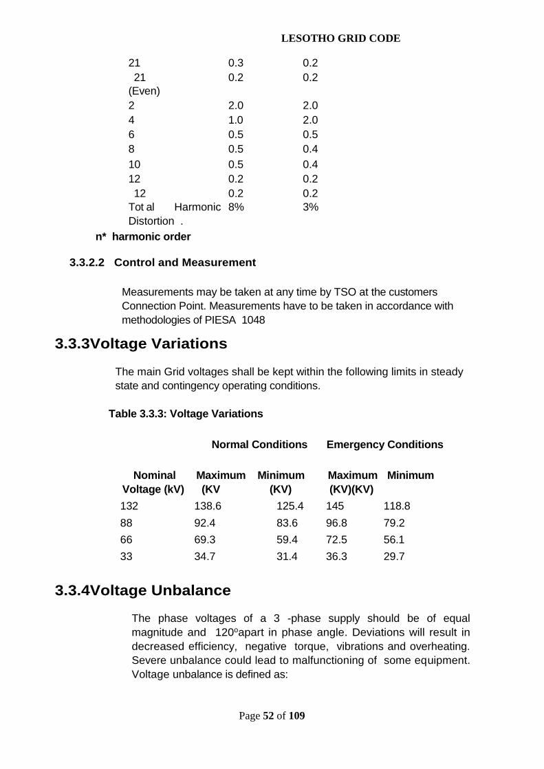
LESOTHO GRID CODE
Page 52 of 109
21 0.3 0.221 0.2 0.2
(Even)2 2.0 2.04 1.0 2.06 0.5 0.58 0.5 0.410 0.5 0.412 0.2 0.212 0.2 0.2
Tot al Harmonic 8% 3%Distortion .
n* harmonic order
3.3.2.2 Control and Measurement
Measurements may be taken at any time by TSO at the customersConnection Point. Measurements have to be taken in accordance withmethodologies of PIESA 1048
3.3.3Voltage Variations
The main Grid voltages shall be kept within the following limits in steadystate and contingency operating conditions.
Table 3.3.3: Voltage Variations
Normal Conditions Emergency Conditions
Nominal Maximum Minimum Maximum MinimumVoltage (kV) (KV (KV) (KV)(KV)132 138.6 125.4 145 118.888 92.4 83.6 96.8 79.266 69.3 59.4 72.5 56.133 34.7 31.4 36.3 29.7
3.3.4Voltage Unbalance
The phase voltages of a 3 -phase supply should be of equalmagnitude and 120oapart in phase angle. Deviations will result indecreased efficiency, negative torque, vibrations and overheating.Severe unbalance could lead to malfunctioning of some equipment.Voltage unbalance is defined as:

LESOTHO GRID CODE
Page 53 of 109
Voltage Unbalance = Deviation between highest and lowest phasesAverage voltage of three phases
Balancing loads on individual phases will help greatly in avoiding unbalancedvoltages.
3.3.5 Voltage Fluctuation and Flicker Severity
If the voltage fluctuates, the luminous intensity of the lamps and TVs willfluctuate correspondingly. If the fluctuation is of a magnitude andfrequency perceptible to the eye, it becomes flicker. Flicker could rangefrom annoying to complete interference of normal activity. Flicker is notusually produced by the power System but by customer loads such asarc furnaces, compressors, starting of large motors, etc. Since voltagefluctuation of the System affects other users on the same System, TSOshall direct the management of flicker on its lines and station buses.At the same time, flicker-generating loads connected to the System haveto be controlled. TSO reserves the right to disconnect any excessiveflicker generating load until the Grid User rectifies the problem.
3.3.5.1 Indicator of Quality for System Flicker
Flicker is the impression of unsteadiness of visual sensation induced by alight stimulus whose luminance or spectral distribution fluctuates withtime. It is generated by customers and is indicated by the short-termflicker severity index Pst, as defined in IEC Standard 61000-3-7and measured with a flicker meter that meets the specification of IECStandard 868 or IEC Std 61000-4-15. For the purpose of regulation, Pst,the short-term flicker severity index, is selected as the indicator ofquality. Pst is considered to be the measure of visual severity of flickerderived from a time series output of a flicker meter over a ten-minuteinterval.
3.3.5.2 Limits
Pst = 1, which is equivalent to the threshold of perception, is the allowablelevel of flicker on the Transmission System. Tolerance for customer-generated flicker varies with the relative strength (short circuit ratio) ofthe load and voltage level. Limits are given in the following table.
Table 3.3.5: Limits of flicker produced by Users
Short Circuit Ratio(SL/SCC ) Voltage Pst
SL/SCC ≥ 0.04 HV0.37

LESOTHO GRID CODE
Page 54 of 109
SL/SCC ≥ 0.04 HV 0.8
3.3.5.3 Monitoring Control and Measurement
Substations, which supply heavy industrial loads are targets for flickermonitoring.Other substations and Connection Point will be selected formonitoring on a random basis.
3.4 Reliability Standards
System reliability of the Grid includes three aspects:
System adequacySystem securityService reliability
The compliance to System adequacy and security reliability standards shall be as specifiedin Section 4 of this Grid Code.
3.4.1 Service ReliabilityThe points where electric power is supplied from the Transmission System to theUsers (distribution companies, another Transmission System) are called delivery points orGrid supply points. Outages at these points directly affect the users of the Grid. Thereliability level at the delivery points is therefore an indication of the quality ofservice provided by TSO to its users.
Service reliability of the Grid is indicated by:
a) Number of loss of supply incidents at the deliverypoints
b) Average duration of loss of supply incidents at thedelivery points
These service reliability parameters will be determined for individual delivery points andagreed with TSO by Users.
Note: Scheduled outages, which are communicated to theconsumers beforehand and load shedding due to capacity shortage,are not counted.
3.5 Power Factor3.5.1 General description
It is desirable that loads on the System have power factors at or close

LESOTHO GRID CODE
Page 55 of 109
to unity as that represents the most efficient use of the Systemcapability and the least loss of energy. It also eliminates many transientstability problems. Any load with a power factor lower than 93% isimposing an unfair burden on the Transmission System and other Users.
3.5.1.1 Limit
The minimum power factor allowed is 93%.
3.5.1.2 Control and Measurement
Power factor measurements are made continuously in conjunction withthe voltage measurements. Loads with inherent low power factors shouldautomatically include power factor correction equipment to correct theproblem.
3.5.1.3 Penalty
A user with power factor worse than 93 % may be refused connection tothe transmission Grid until the problem is rectified. Alternatively,apenalty will be imposed based on load level and annualised cost ofpower factor correction capacitors.
3.5.2 Reactive Power Requirements
In general the Distribut ion Companies shall not depend on TSO forreactive power support. DSO and other Grid Users shall provide reactivecompensation for their System. DSO and other Grid Users shall ensurethat consumers having inductive load install capacitors so that at theinterface with TSO the power factor is not less than 93%.
SECTION 4
PLANNING CODE
4.1 IntroductionProvisions of this Section are intended to enable TSO to produce a NetworkDevelopment Plan and a Power Development Plan for demand and supplybalance. This will be done in consultation with all Grid users in order toensure an efficient, coordinated, secure and economical Grid networkand power developments that will satisfy future demand requirements. TheSectionidentifies the planning requirments for the Transmission andTransmission Systems and the Generation System including Imports options.
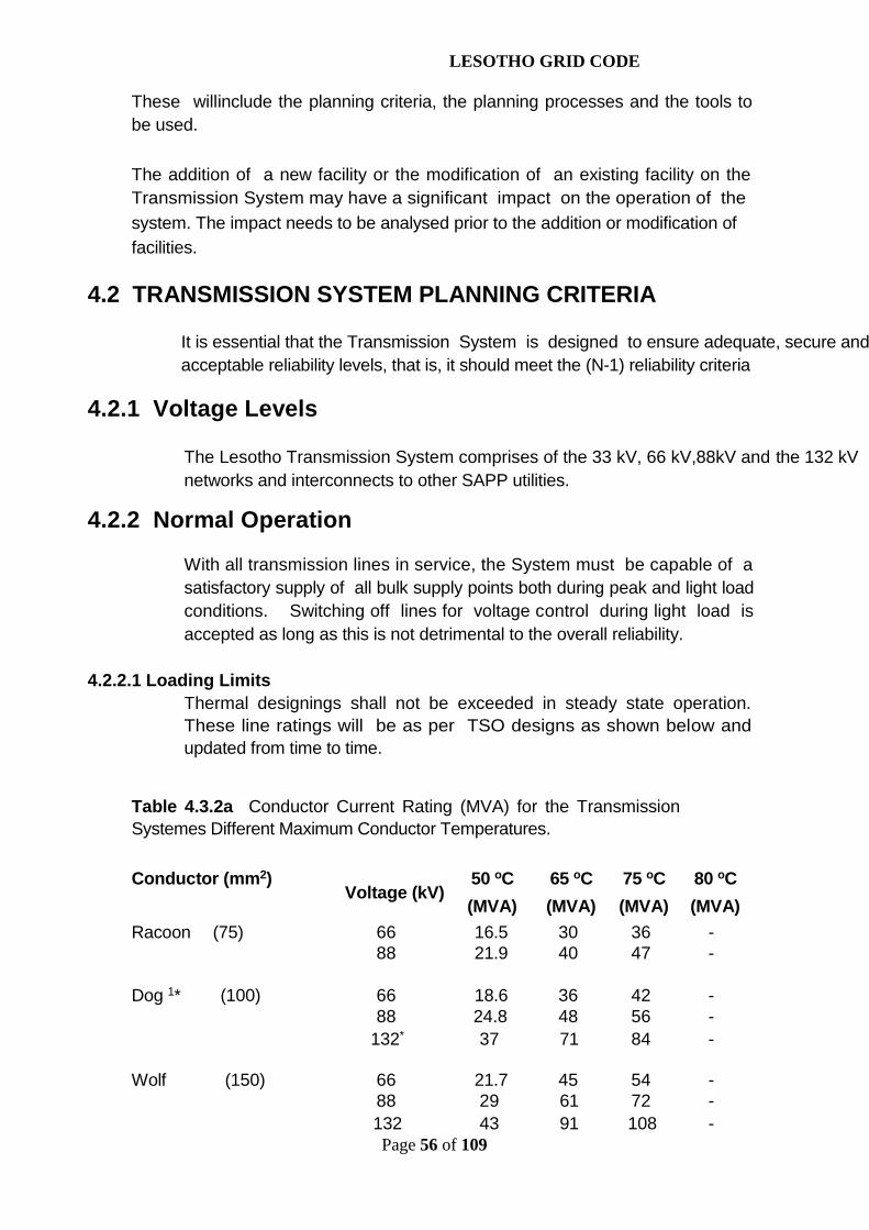
LESOTHO GRID CODE
Page 56 of 109
These willinclude the planning criteria, the planning processes and the tools tobe used.
The addition of a new facility or the modification of an existing facility on theTransmission System may have a significant impact on the operation of thesystem. The impact needs to be analysed prior to the addition or modification offacilities.
4.2 TRANSMISSION SYSTEM PLANNING CRITERIA
It is essential that the Transmission System is designed to ensure adequate, secure andacceptable reliability levels, that is, it should meet the (N-1) reliability criteria
4.2.1 Voltage Levels
The Lesotho Transmission System comprises of the 33 kV, 66 kV,88kV and the 132 kVnetworks and interconnects to other SAPP utilities.
4.2.2 Normal Operation
With all transmission lines in service, the System must be capable of asatisfactory supply of all bulk supply points both during peak and light loadconditions. Switching off lines for voltage control during light load isaccepted as long as this is not detrimental to the overall reliability.
4.2.2.1 Loading LimitsThermal designings shall not be exceeded in steady state operation.These line ratings will be as per TSO designs as shown below andupdated from time to time.
Table 4.3.2a Conductor Current Rating (MVA) for the TransmissionSystemes Different Maximum Conductor Temperatures.
Conductor (mm2) 50 oC 65 oC 75 oC 80 oCVoltage (kV)
(MVA) (MVA) (MVA) (MVA)Racoon (75) 66 16.5 30 36 -
88 21.9 40 47 -
Dog 1* (100) 66 18.6 36 42 -88 24.8 48 56 -
132* 37 71 84 -
Wolf (150) 66 21.7 45 54 -88 29 61 72 -132 43 91 108 -

LESOTHO GRID CODE
Page 57 of 109
Twin Wolf (2x150) 88 58 121 144 -132 87 182 216 -
Single Lynx (175) 66 22.7 50 59 -88 30.3 66 79 -132 45 99 118 -
Twin Lynx (2x175) 88 61 132 157 -132 91 198 236 -
Single Panther (200) 66 23.8 54 64 -88 31.7 72 86 -132 48 108 128 -
Twin Panther (2x200) 132 95 215 257 -
Bear 2* (250) 132 50 122 146 128
Single Bison (350) 88 - 100 120 193132 - 149 179 385
Twin Bison (2x350) 132 - 299 359 963
Thermal design ratings shall not be exceeded in steady stateoperation.
4.2.2.2 Voltage Limits
In steady state operation, main Grid voltages shall be kept withinthe following limits:
Nominal Maximum Minimum(kV) (kV/p.u.) (kV/p.u.)132 138.6/1.05 125.4/0.9588 92.4/1.05 83.6 /0.9566 69.3/1.05 62.7/0.9533 34.6/1.05 31.4/0.95
4.2.3 Outage Conditions
The following outage criteria apply to the operation of the interconnectedTransmission System. In general, the criterion requires that there shall beno loss of load for single contingency faults.

LESOTHO GRID CODE
Page 58 of 109
4.2.3.1 Stability Criteria
The System shall remain stable for a single line to ground faultwith unsuccessful high-speed three pole re-close and definitethree pole tripping.
The System shall withstand a sudden outage of any generatingunit or block of units connected to the same transformer withoutloss of supply. (However, load shedding following an outage ofthewhole power station is accepted).
4.2.3.2 Loading Limits
For a single outage, the following load limits shall be applied once the newsteady state has been reached, but prior to any operator intervention.
- Short-time (10 minutes) overloads of up to 15% ontransmission lines shall be accepted if generationrescheduling is available (i.e. before operator action canbe taken).
- Short-time (10 minutes) overloads of up to 15% on transformersshall be accepted.
Limited overloads for short periods are not considered to bring theconductor temperature to critical values neither are they expected toincrease sags too much.
4.2.3.3 Steady State Voltage Limits
For a single outage, the following voltage limits shall be applied once thenew steady state has been reached, but prior to any operator intervention.
- Main Grid voltages shall be kept within:
Nominal Maximum Minimum(kV) (kV/p.u.) (kV/p.u.)
- 33 kV: 36.3/1.10 29.7/0.90- 66 kV: 72.6/1.10 59.4/0.90- 88 kV: 96.8/1.10 79.2/0.90- 132kV: 145.2/1.10 118/0.90
4.2.3.4 Transient Voltage Deviations
The transient response of the System following a disturbance shall

LESOTHO GRID CODE
Page 59 of 109
be investigated if bus voltages swing outside the range of 0.8 to1.2 p.u.for more than 500 milliseconds.
4.2.3.5. Transformer Loading Limits
The following transformer loading limits shall be applied followingtransformer outages. The set limits are based on IEC standards38 or TSO design, assuming an ambient temperature of 30 deg. C.Momentary loading based on I EC standards 38 or TSOdesign is for a period of 30minutes.
Table 4.3.4: 132 kV, 88 kV, 66 kV and 33kV Transformer Loading (MVA)
LOADING LIMIT (MVA)TRANSFORMER MOMENTARILY CONTIUNUOUSLYNAMEPLATE RATING(MVA)
40MVA(ONAF) 50 40
20MVA (ONAN) 25 20
10MVA (ONAN) 12.5 10
5MVA (ONAN) 6.3 5
4.2.4 Other Criteria4.2.4.1 Losses
Costs of losses shall be evaluated as part of the economic analysis ofthe different Transmission System alternatives. The analysis shallincludeevaluations on optimum line design (voltage , conductor typeand configuration).
4.2.4.2 Wayleaves and Clearances
The standard way leaves shall be as follows: -
11kV 8 m

LESOTHO GRID CODE
Page 60 of 109
22 kV 8 m
33 kV 13 m
66 kV 14 m
88 kV 16 m
132 kV 18 m
In addition, the following line clearances in metres shall be observed: -
Normal operating Over roads Minimumvoltage between groundline conductors clearances(in kV )(inmetres ) (inmetres )
Up to and including 33 6.5 5.566 6.9 6.388 7.5 6.3132 7.5 6.3
4.2.4.3 System Protection Schemes
(1) Each Usershall take all reasonable steps to protect its own plant.
(2) All plant connected directly to a TSO Grid shall comply with the Grid Code protectionrequirements described in section 7. Further detailed protection applications, insofar asthe equipment of one Usermay have an impact on another, shall be agreed to in writingby the relevant User. Usersthat have customers connected directly to the TSO Grideareresponsible for ensuring that such customers comply with the relevant protectionstandards.
(3) The User shall co-operate to ensure adequate protection co-ordination.
(4) Customer’s protection dependability shall not be less than 99% and the customershall ensurethatQOS standards are adhered to.
4.2.4.4 Steady State Stability Limits
When evaluating the System's transfer limits, care should be taken todesign the System with adequate margin to voltage collapse phenomena.Transfer limits must ensure that a single outage does not bring theSystem into instability situation. The System should be regarded asunacceptable from a planning point of view if it runs out of voltage

LESOTHO GRID CODE
Page 61 of 109
control range following a single contingency.
4.2.4.5 Maintenance Restrictions
The proposed "N - 1" criterion used for the Transmission System does nottake into account outages due to maintenance. The reason is that it hasbeen assumed that no major maintenance will be carried out duringpeak load, which is considered to determine the design of theSystem. Depending on circumstances, it might be necessary for theplanner to evaluate the System even for "N - 2" conditions, and weighcosts and benefits of designing the System to meet such a criterion.
In general, when evaluating different development strategies, thosealternatives that are foreseen to better meet requirements duringmaintenance, should be preferred.
4.3 NETWORK DEVELOPMENT APPROACH AND METHODOLOGY
4.3.1 ObjectivesThis Section presents the approach and methodology to be adopted inthe transmission planning process in TSO. The aim is to lay aframework for the planning aspects involved in transmission andTransmission System planning covering the required inputs, the expectedconstraints, the expected results and the basic steps to be taken.
The planning and design of the Transmission System is aimed atproducing a network that is capable of transmitting electrical energyfrom the generating plants to the load centres in an economic, safe andreliable manner .
4.3.2 Approach
The normal approach in network planning is to carry out a technicalanalysis on the most promising development plans based on attainingcertain reliability levels.
Transmission System reliability levelsshould be analysed usingplanning criteria that define allowable system responses. The criteriashould be stringent enough to ensure a high quality of supply yet it mustalso be realistically cost effective in today' s competitiveenvironment.The criteria may be based on either deterministic orprobabilistic approaches. The deterministic approach involves thespecifying of allowable System response to specified contingencies ordisturbances. Probabilistic approach involves limiting the risk of System
LESOTHO GRID CODE
Page 62 of 109
failure or even limiting customer impact such as risk of loss of load,on the basis of outage statistics of System components.
Recent years have seen several developments in probabilisticreliability assessment procedures, which have been used to substantiatethe need for System expansions. These have now been appliedwidely by some utilities. Reliable and detailed data for making failuremodels for most System components have been established havingbeen assisted by reliability-based maintenance approaches beingused in operating the network. However , the deterministic approach isviewed as adequate for the Lesotho System.
The criteria developed apply to both static and dynamic conditions,requiring that theSystem response to certain disturbances fall within prescribed limits.These limits often specify permissible voltage ranges, componentloadings, frequency deviations and rotor angles. The limitation of thedeterministic approach is that it does not provide a means of quantifyingthe worth of improved supply, which is required to justify Systemreinforcements. The deterministic approach is considered to be thebest for the TSO System.
4.3.3 Methodology4.3.3.1 Basis
The System Transmission System developments plans shall be basedon load forecast, Generation System development plan andagreements for transactions with other utilities. Any external factors thatmight affect Transmission System planning should be addressed in theplanning process.
Figure 4.4.3 illustrates the stages that are involved in the transmissionplanning process. An essential feature of this process is the screening ofalternatives from an economic and technical point of view to avoidcarrying out detailed studies on alternatives that are not competitive. Thenumber of alternatives to be investigated is therefore reduced from onestage to the other . The remaining alternatives are then subjected tomore detailed studies.

LESOTHO GRID CODE
Page 63 of 109
Figure 4.4.3 Stages in the Transmission Planning Process.
4.3.3.2 Grid Planning Studies - Technical Analysis
TSO shall carry out Grid planning studies to ensure Reliability, Safety,Security and Stability of the Grid for the following:
no
yes
yes
Cost alternatives & carry out least cost analysis.Carry out economic cost benefit analysis on least cost alternatives
Assess technical feasibility of alternatives
with reference to transmission planning criteria
Generate alternatives for network expansion & reinforcement
Assess Existing Network against Planning Criteria:Loadflow, short circuits & stability at different stages
Input Data: Load ForecastsGeneration Data & ScenariosNetwork Data & Operating PhilosophyStatutory & Regulatory limitations
Are economiccriteria satisfied?
Are economiccriteria satisfied?
Furher refine alternatives: substation basic layout;protection requirements;
other issues.
Recommend a transmission expansion plan
Carry out financial cost benefit analysis on the lease cost alternative

LESOTHO GRID CODE
Page 64 of 109
Preparation of the Transmission Development Plan (TDP)to be integrated with the Power Development Plan (PDP.
Evaluation of the Grid reinforcement projects and Evaluation of any proposed user development , which is submitted to
the TSO in accordance with the application for connection.
The Grid planning studies shall be conducted periodically to assess thebehaviour of the Grid during normal and outage conditions; and alsoduring transients induced by disturbances. The first screening process isthrough the technical analysis of the identified transmission expansionalternatives. The required inputs for this process are:
load forecasts existing network committed expansion plans generation scenarios transactions with other utilities
The need for transmission expansion plans is detemined by identifyingany transmission constraints, in future based on the input data. Basicalternative development plans that would solve these problems are listedand engineering judgement is applied to screen these alternatives andremain with the best.
The best alternatives are assessed for their technical soundness against the planningcriteria discussed above. The techniques applied ensure that all components are operatingwithin prescribed limits and that voltages are within permissible ranges. Load flow analysistechniques are used at this stage of the process. For networks with obvious transientstability problems, initial nvestigations of System dynamic response will also be carried outat this stage. Fault analysis is shall be carried out at a later stage of the planning process.System reliability analysisshall be required as a basis for evaluating alternatives.
Transmission planning studies must be performed as necessary todetermine the impact on the interconnected Transmission System whenconnecting new and/or modified generation, transmission, or end-usefacilities to ensure the security and adequacy of the TransmissionSystem. The results of these analyses will be used to determine ifmodifications must be made to maintain the reliability of theTransmission System. A detailed interconnection study is made up ofthe following components:
Load Flow AnalysisFault AnalysisStability Analysis

LESOTHO GRID CODE
Page 65 of 109
a)Load Flow Analysis
A model of the power System is used to simulate certain specifiedoperating conditions. Load flow studies shall be performed toevaluate the behaviour of the existing and planned Grid facilitiesunder forecasted maximum and minimum load conditions and to studythe impact on the Grid of the connection of new generation plants,loads or transmission lines. The results predict power flowmagnitudes and voltage levels under the loss of any individualSystem element . The load flow analysis enables the prediction ofequipment overloads and the determination of excessive steadystate voltage drops, which may be encountered.
b)Fault Analysis
Fault analysis is performed to determine the effect ofequipment additions or modification on the System fault currents.The studies also identify the most severe conditions that the Gridequipment may be exposed to. The fault studies data is used toevaluate the impact of the new or modified installation on theinterrupting capability or rating of the previously installedequipment such as circuit breakers and switches.
TSO shall maintain an up to date fault level database, which shouldbe made available on request by Grid Users. TSO shall inform theGrid User , if fault levels at a Connection Point are likely toimpact adversely on the User s Equipment connect ed to the Grid.
c)Stability Analysis
Stability analysis is performed to determine the TransmissionSystems response to a sudden change in the state of the System dueto faults on the System and unit outages. The stability analysis willdetermine:
i. Unit / station stability during faultsii. Voltage levels and deviationsiii. Frequency levels and deviationsiv. Synchronous generator rotor oscillations, real and reactive
power outputs
4.4.3.3 Economic Analysis
Electricity plays a major role in the economic development of the countryas a whole. Therefore the transmission development plans that result ina reliable network are core elements in the strategy for raising the

LESOTHO GRID CODE
Page 66 of 109
economic and social welfare of citizens. This involves demonstratingthat the proposed project is likely to contribute significantly to thedevelopment of the entire economy to justify the use of the resourcesenvisaged for the project.
Cost-benefit analysis provides a tool for assessing the worth of a projectto society. Where alternative projects are aimed at satisfying the sameobjective, cost benefit analysis shall be used to compare thealternatives. In transmission planning, least-cost analysis should be usedto eliminate some alternative expansion plans.
4.4.3.4 Environmental Analysis
The environmental analysis focuses on the project's impact on theenvironment , both human and bio-physical, during construction, operationand de-commissioning. The environmental impact study should providebaseline information to be used in monitoring environmental impacts andassessing the effectiveness of mitigating measures. Both negative andpositive environmental impacts should be identified and quantified to theextent possible.
4.4.3.5 Financial Analysis
Financial analysis of a project involves determining the cost and revenueof the project . The costs give an indication of the funds needed tocomplete the project , while the revenue and sources of funds determinewhether a project can sustain its financial obligations and have adequateworking capital as well as generate sufficient cash flow to meet theproject operational expenses.
The technique provides a measure of the profitability of the project.Financial analysis should only be carried out on the screenedalternatives that have been proved to be economically viable.
4.4.3.6 Final Selection
The final transmission projects that would have gone through the abovestages will then be incorporated in the System Development Plan (SDP).
4.3.4 Transmission Planning Tools
TSO shall employ planning tools that are currently available in themarket.
4.4POWER GENERATION DEVELOPMENT PLAN

LESOTHO GRID CODE
Page 67 of 109
The objective of a Power Development Plan is to establish when, where andwhat type and size of plant to build, in order to ensure an economic andreliable supply of forecasted load within a given planning period.
Thus four basic questions have to be answered in the course of the planning process.These are:
WHAT capacities to install to ensure demand and supply balance?WHAT capacities to install to ensure an appropriate level of reliability?HOW to pick the best combination among the different technologies athand now and in future?WHEN is the proper time to incorporate them into the System?
4.4.1 Planning ApproachTSO shall use a Least Cost Planning approach. Apracticalframework for least - cost utility planning should explicitlyconsider the major issues in resource planning and facilitate riskmanagement . In this framework, demand and supply side options aresimultaneously evaluated for cost effectiveness.
The Dynamic System Optimisation (DSO) model is used forintegrated demand, supply and financial planning. The DSOmodel performs the following functions:
Optimises supply side options for conventional and renewableresources over theentire planning horizon.
Optimises demand side options including conservation and peakreducing programs.
Selects new plants and Demand Side Management programmesto satisfy emission restrictions on SOx, NOx and particulates.
Satisfies reliability requirements to meet the reliabilitycriteria.
4.5.LOAD FORECASTING
Electricity power supply and demand must be balanced at all timesand the challenge for any electricity supply company is to providea reliable electricity supply service at least cost . To meetthischallenge it is necessary to plan for a level of investmentthat meets future energy consumption and maximum demand givenby a load forecast

LESOTHO GRID CODE
Page 68 of 109
The major uncertainties in forecasting and planning should beexplicitly recognised in the planning process. In order tominimise load-forecasting uncertainties, the load forecast forgeneration planning will shall mainly comprise the low case, basecase and high case as provided and updated by TSO on anannual basis or when the need arises..
Demand and energy forecasting is mainly classified into threeranges: short, medium and long-term. The short term forecast isuseful in determining unit commitment andeconomic dispatch; medium term forecasting is required for fuelprocurement, maintenance scheduling and diversity interchanges;whereas the long- term forecast (annual peak and energyconsumption forecast) is necessary for System expansion planningand financial analysis. Energy and demand are forecast on anannual basis for the 20-year planning period so as to provide asufficient time horizon in providing future development options.TSO shall employ current loadforecasting software, which includesbut not limited to Model for Analysis of Energy Demand.(MAED).
4.5.1. Satisfying the Load Forecast / Developing Scenarios
After the Load Forecast is produced it is matched against thecapacity and energy resources of the existing plants to seewhether they can satisfy the requirements over the planningperiod. If the existing plants cannot meet the load forecast itthen becomes necessary to find the best possible ways of meetingthe demand reliably and at least cost , which is whatPower Development Planning is all about. Technically equivalentscenarios have to be evaluated to determine the least cost , takinginto consideration three major criteria:
a) Criterion 1 (Reliability Criterion)
The minimum reserve level to be carried on the System shall beas per SAPP Operating Rules.
b) Criterion 2 (Security Criterion)
The minimum level of internal generation shall have as a long-termobjective, capacity equal to or greater than 100% of demand.Internal generation shall be committed when existing reservelevels drop below Criterion 1.
c) Criterion 3 (Economic and Financial Criterion)
LESOTHO GRID CODE
Page 69 of 109
For economic considerations Firm Imports may exceed thereserve margin limit as long as Criterion 2 is met.
4.5.2 Demand Side Management (DSM)Customer demand can be influenced by utility actions. Demand-sideoptions are available, viable and potentially useful alternatives totraditional generation-based strategies. Demand side management is theplanning and implementation of those utility activities designed tonfluence customer use of electricity in ways that will produce desiredchanges in the utility’s load shape. The rationale for DSM as a part ofoverall utility planning is:
The demand for electricity is within utility’s control .The timing and shape of load instead can
be influenced by direct utility action in ways that contribute tomeeting utility objectives.
Demand side options can be used to complement or substitutefor supply-side options.
The benefits are the savings in avoiding energy supply costs. These avoidedcosts are the marginal costs of the supply resource replaced by DSM . Theyinclude the reduction of transmission, distribution, generation and capacitycosts for periods when the load has been reduced.
4.5.3 Options Available
All available options such as, but not limited to the following shall be consideredin the optimised generation expansion plan.
Thermal options Hydro options
Imports Non conventional and renewable energy sources
4.5.4 Operating Environment
The characteristics of the utility planning environment suggest four principlesfor improved decision making:
Evaluate decisions as they affect customers and investors Analyse the effects of uncertain variables on the customer ' s
cost of service and the investors return Consider the long - term consequences of investment
LESOTHO GRID CODE
Page 70 of 109
decisions for the relevant range of uncertaintiesand for major contingencies.
Ensure that decisions are well documented withsupportive studies and rationale for the purposes of publicand regulatory
retrospective review.
4.6 PLANNING DATA EXCHANGE
In order to ensure adequate planning and development of theTransmission Grid, TSO will require information pertinent to planningthat may be resident in other companies such as DSO and any othercustomers connected to the Grid and any other suppliers of power in theGrid. TSO should have full access to all the relevant datafrom these companies as and when the need arises. TSO shall providestandard data format for this purpose. A more detailed account of datarequirements is given in Section 8 of this Grid Code. The informationrequirements shall basically include, but not limited to:
Historical Energy and Demand Energy and Demand Forecast Dependable capacity LEA and/or SAPP approved criteria DSO or any other User or Customer System Data
LESOTHO GRID CODE
Page 71 of 109
SECTION 5
OPERATIONS CODE
5.1 Introduction
TSO is entrusted with the responsibility to transmit power and energy from the generatingunits and/or imports to the end Users in a safe, reliable and within specified power qualityparameters. TSO transmission grid is operated in parallel as an interconnected grid withother SADC utility transmission networks to form the Southern African Power Pool (SAPP).In pursuance of harmonised interconnected operation the SAPP has developed operatingguidelines that are subscribed to by all the operating members. TSO takes cognisance ofthe SAPP requirements in developing and implementing of its own guidelines andprocedures.
5.2Purpose
This Operations code is intended to enable TSO to operate a well-coordinated, safe and secure transmission grid that shall deliver qualitypower. The code includes guidelines on principles and procedures forproviding system services, network switching, demand/supply balancing,operational planning and eventsreporting. These shall be done inconsultation with all grid users.The code deals with the following issues: -
Pre-dispatch and post-dispatch planning. Real-time system monitoring and control. Communication during normal and emergency
conditions. Maintenance planning, co-ordination and
execution.Generation scheduling and dispatch.
Safety coordination.
5.3 Responsibility
Equipment ownership and demarcations shall be as per connectionagreements between TSO and the grid Users. Control, Operation andmaintenance of any equipment shall be as detailed in the Power SupplyAgreement (PSA), Power Purchase Agreements (PPA) and any otheragreement that TSO may have with any grid Users as illustrated in the

LESOTHO GRID CODE
Page 72 of 109
fugure below.
All grid Users shall endeavor to operate their respective systems insynchronism at all times. Safety of personnel and Security of powersystem shall be accorded higher priority than economicconsiderations.
PPAPSA
LARGECUSTOMER
S
SAPP
DSO
GRIDNETWORK
SYSTEM OPERATOR
DANAMDTSO
SUPPLY
IPP
SAPP
OTHERS

LESOTHO GRID CODE
Page 73 of 109
5.4 System Monitoring
TSO shall maintain a control centre that is manned 24 hours a day by an appropriatenumber of personnel for the purpose of system monitoring and control. The control centremust be equipped with a computer based supervisory control data acquisition and energymanagement system.
For effective operation of the transmission grid, TSO shallcontinuously in real time monitor the following: -
(a) Actual generation per unit (MW).(b) Actual active power (MW) drawn by grid Users(c) Tie line interchange(d) Reactive power (MVAr) flows into or out of TSO grid.(e) System frequency(f) Voltage profiles in all stations and points of connection(g) Equipment loadingEqually important all information on generator trips shall be
urgently conveyed to TSO System Operator.
5.5 System Services
System services are all services essential for the proper functioning ofthe transmission grid and which determine power quality. These servicesinclude, but not limited to, frequency control , voltage control andoperating reserves. TSO shall ensure that the transmission grid isoperated with adequate levels of these services. TSO shall adviseGrid Users of the required contribution levels of the services where theyare mandatory and shall itself , procure adequate levels where TSO has toself provide.
5.5.1 Frequency Control Service
TSO shall operate the grid in a manner that provides adequatefrequency control within applicable limits at all times in order to maintainthe security and integrity of the same. Both primary and secondaryfrequency control shall be as per recommendations from TSO.
5.5.1.1 Frequency Range
The frequency within the Southern African Power Pool (SAPP) is maintained and controlledjointly by all the interconnected utilities. The normal frequency shall be 50.0Hz with astatutory range of 48.5Hz and51.5Hz. The operational range, which is narrower than the

LESOTHO GRID CODE
Page 74 of 109
statutory band, shall be as recommended by the SAPP or TSO when operating in theinterconnected or islanded mode respectively.
5.5.1.2 Frequency Control
a) All generators must operate under the control of a governor systemat all times when synchronised to the grid.
b) All governors shall be capable of droop adjustments of between 3%and 6%. The actual governor settings to be implemented for
primary frequency control shall be as specified in the connectionagreement.
c) No deliberate time delays shall be introduced in the governorcontrol systems.
d) Frequency dead bands shall be as per recommendation from TSOin consultation with SAPP utilities.
e) TSO shall employ Automatic Generation Control (AGC) and manualactions for secondary frequency control. Generators required to be
under AGC shall be specified in the connection agreement and those notoperating under AGC shall continue to follow dispatch instructions fromthe System Operator. The AGC shall meet the frequency and tie-linestandards defined by SAPP.
5.5.2 Voltage Control Service
Voltages on the grid and at points of connection shall be maintainedwithin the limits specified under section 5 .5 .2 .1 of this code. In caseswhere the voltage limits are unique to the point of connection these shallbe as specified in the connection agreements.The duration and extentof voltage fluctuations shall also be limited under fault conditions.TSO shall employ both static and dynamic methods to maintainvoltage stability, maintain voltages within limits and minimise systemlosses using methods that include but not limited to the following.
(a) Transformer tap changing.(b) Reactor and capacitor switching.(c) Static Var Compensators(d) Generator reactive power capability.(e) Demand management.(f) Transmission lines charging capacitance
5.5.2.1Voltage Range

LESOTHO GRID CODE
Page 75 of 109
The main grid voltages shall be kept within the following limits in steadystate and contingency operating conditions so as to minimise systemlosses and to maintain quality of supplies.
Normal Conditions Emergency Conditions
Nominal Maximum Minimu Maximum MinimumVoltage (kV) (KV) m (KV) (KV)
(KV)132 138.6 125.4 145 118.888 92.4 83.6 96.8 79.266 69.3 59.4 72.5 56.133 34.7 31.4 36.3 29.711 11.6 10.5 12.1 9.9
Where standing instructions or special dispensations are in place thevoltage might not follow guiding limits in the table above.
5.5.2.2 Voltage Control
a) Grid voltages will continuously be monitored and controlledaccordingly. TSO shall adjust grid voltages usingavailable control facilities.
b) Generator excitation systems shall be normally operatedunder a continuously acting Automatic Voltage Regulator(AVR) which shall be set to maintain a constant terminalvoltage.
c) The TSO shall instruct the generators on what terminalvoltage to maintain.
d) Generators may only disable the action of AVR if suchaction assists in improving on the reliability of thegenerator.
e) As an emergency measure TSO may implement loadshedding to prevent lower voltage limit excursions.
f) Line switching will be implemented only if it doesnot jeopardise system security.
5.5.3 Equipment loading
TSO shall continuously monitor the loading on all plant andequipment on the transmission grid. Thermal design ratings shallnot be exceeded in steady state operation and for single outage.Short time overloads of up to 15% on transmission lines and

LESOTHO GRID CODE
Page 76 of 109
transformers shall be accepted if generation rescheduling isavailable (i .e. before operator action can be taken). OtherwiseTSO shall implement load management to relieve over loadedcircuits.
Grid Users drawing power from TSO grid shall ensure that their loads donot affect TSO grid system in terms of causing any:
1. Unbalance in the phase angle and magnitude of voltage at thepoints of connection beyond the limits prescribed by TSO.
2. Harmonics in the system voltage at the interconnection pointbeyond the limits prescribed by TSO.
Should any one of the above two prevail TSO may direct theUser(s) to take appropriate measures to remedy the situation.
5.6 Operational Planning
TSO shall be responsible for developing consolidated demandforecast , demand control procedures, outages and contingency plans.
5.6.1 Demand and Supply planning
All grid Users drawing power from TSO grid shall provide TSO, forall points of connection, with
i. Estimates of demand per month for the year aheadii. Estimates of demand per day for the month ahead.
Similarly each generator shall provide TSO with estimates of generationavailabilityper monthfor the year ahead and per day for themonth ahead.
TSO shall match the consolidated demands with consolidated generationavailability and plan for demand control to ensure that there is a balancebetween the available power / energy and the demand (inclusive of systemlosses and required reserves).
5.6.2 Outage Planning
TSO and each User shall prepare an outage programme for the ensuingfinancial year for compilation of the overall outage plan for TSO grid.Each User shall obtain approval from TSO prior to availing the outage.However , TSO is authorised to defer any planned outage in case of anyof the following events: -

LESOTHO GRID CODE
Page 77 of 109
a) Major grid disturbanceb) Security constraint dispatchc) Unavailability of other equipment that has to be conditionally
in service for the outage to go ahead
d) Any other event in the system that may have an adverse impact onsystem security by the proposed outage.
5.6.3 Contingency Planning
The contingency plan and black start procedures shall be prepared byTSO in consultation with grid Users. The restoration process shall takeinto consideration generator capabilities and operational constraints of thetransmission network. All users shall be aware of the requisite steps tobe taken during the following: -
a) Partial system blackoutb) Total system blackoutc) Synchronisation of system islands
During system restoration following a disturbance emergency standardsof frequency and voltage shall apply.
Users drawing load will identify non-essential components of their loadfor the purpose of switching them off during system contingencies to aid insystem restoration. The non-essential loads can be switched on onlywhen the system is restored as advised by the TSO. All Users shall payspecial attention in carrying out the procedures so that secondarycollapse due to undue haste or inappropriate loading is avoided. Despitethe urgency of the situation, careful, prompt and complete logging of alloperations and operational messages shall be ensured by allUsers to facilitate subsequent investigation into the incident and theefficiency of therestoration process.
5.7 Dataand Records Storage
TSO shall maintain a historical database of power and energy demand.This information is very useful as input to demand forecasting and forreconciliation and reporting.
5.7.1 Demand and Energy Data
LESOTHO GRID CODE
Page 78 of 109
The following historical data shall be maintained to facilitate SystemStudies:
Energy produced by source ofenergy Energy sent out bysource of energy
Energy at the Connection Points and at substaions System maximum demand Substations maximum demand Substations demand at the time of the System Peak Substations demand at the time of the System off peak
The data shall be captured on half hourly basis and an electronic copyshall be kept and hard copy may be produced on request.
5.7.2 Safety records
Legibly written Switching Logs, in chronological order, shall be maintainedby both designated Senior Authorised persons of TSO and Users for alloperations and messages relating to safety co-ordination sent andreceived by them. All Switching Logs and safety documents issued forwork on plant and / or equipment shall be retained for a period of not lessthan one year.
5.7.3 Fault Recording And Reporting
TSO shall produce reports for all faults on the TSO grid. Users whoseequipment is faulted and impacts on the TSO grid mustreport the details of such a fault to TSO within 14 days. TSO shallrecord all relevant information pertaining to the fault.
Fault reports shall containthe following information:
a) Date and time of Faultb) Location of Faultc) Circuit Breaker(s) operationsd) Cause of Faulte) Injuries to Persons and/or Damage to Plantf) Load Interrupted and Duration of Interruptiong) Protection Operationsh) Any other relevant information
The fault reports for TSO grid related disturbances shall be made available to

LESOTHO GRID CODE
Page 79 of 109
Users on request.
5.8 Safety CoordinationThis section specifies safety requirements to be used by TSO and all Grid Users so as tomaintain safety of personnel, plant and /or equipment.
5.8.1 Responsibility
TSO shall be the custodian of safety procedures and documentsused when working on plant and / or equipment on thetransmission grid and at all points of connection with the Users. TSOshall not impose these safety requirements for work outside thetransmission grid network and beyond the points of connection.Only Competent Persons authorised by TSO shall be permitted to carryout any work and network switching on the transmission grid andat the point of connection. The safetyrequirements are ascaptured in the LEA Supply Relues.
5.8.2 Authorised Persons
A list of the Senior Authorised persons (names, designations andtelephone numbers) for the TSO transmission grid and for Users atpoints of connection shall be circulated to TSO and all grid Users. Thelist must be updated promptly whenever any of the informationchanges.
5.8.3 Work On Plant and Equipment
Work must commence only after it has been made safe to work onthrough the following steps.
i. Opened (source of power removed).ii. Isolated (physically disconnected form source of power).iii. Safety testediv. Earthed (connected to the earth).v. Safety documents issued
The designated Senior Authorised person shall ensure that adequatesafety precautions are established and maintained throughout the work.The equipment shall only be considered suitable for return to servicewhen all safety documents have been cleared and isolation pointsnormalized.

LESOTHO GRID CODE
Page 80 of 109
5.8.4 AccidentsDuring Work
In the event of an accident during work on the TSO grid or at points ofconnection the following steps shall be taken:
a. Responsible Person stop work and attend to the injured if any.b. Responsible person shall notify Senior Authothorised Person ,who will decide whether work should
continue or not.c. Senoir Authorized Person shall notify system Controller and SafetyOfficerd. Senoir Authorized Person shall produce a preliminary report and notify TSOmanagement, Grid Code Review Panel and LEA within 5 days.e. TSO shall constitute a committee for further
investigationf. Produce a detailed accident report.g. Circulate report internally and to key people in the Users systems.
5.9Communications
Telecommunications are the basic infrastructure that makes remoteoperations of a system possible. It is, therefore, imperative thattelecommunications be highly reliable and available.
TSO and Users shall advise each other of the telephone numbers to beused for operational purposes. TSO shall ensure that all operational linesare monitored for future replay should any disputes arise or as a tool inincident investigation.
5.10Demand Control
Provisions of this section are to enable TSO to implement demandreduction or demand addition in a manner that ensures the continuedbalance between supply and demand.
TSO shall be responsible for issuing instructions to Users fordropping or connecting load under emergency or normal conditions.
5.10.1 Planned Demand Control
In the case of a supply demand mismatch is foreseen TSO will alertUsers drawing power from TSO grid in terms of the times and load

LESOTHO GRID CODE
Page 81 of 109
quantum to be curtailed.
TSO shall consult the Users in producing a load shedding programme that shall befollowed when there is planned load demand control.During emergency TSO may curtailload in a manner that does not strictly follow the agreed load sheddingprogramme.
5.10.2 EmergencyAutomatic Demand Control
Emergency automatic demand control occurswhen there is a sudden loss of generation substantially in excess of spareplant capacity. TSO in consultation with grid Users shall prepare theplan for automatic load shedding during the low frequency conditions.
During periods of low frequency conditions generating stations shallassist through the following:
a. Endeavour to assist the system frequency to rise to 50 Hz, byincreasing generation whenever possible.
b. Not disconnecting manually from the transmission system unlessthere is definite evidence that a complete failure of generation wouldotherwise result.
5.11 Power System Restoration After Blackout
TSO is required to direct and co-ordinate restoration efforts afterblackouts. This can only be achieved safely and quickly by using a well -organised and systematic approach as specified inthis Section.
It is incumbent on all grid Users authorised to carry out switching on thenetwork to be thoroughly familiar with and observe the followingrestoration procedures:
a) TSO and the Grid Users are required to accurately assess theextent of the blackout and the status of plant and equipment , andfrom available information determine the best approach for restoringsupply. , Critical loads shall receive prioty. ,
c) TSO shall direct and co-ordinate system restoration with Usersand interconnected utilities in accordance with standing instruct ions

LESOTHO GRID CODE
Page 82 of 109
and laid down procedures.
d) Generating station Operators shall direct and co-ordinate the start -up of generating machines to be ready for synchronising in accordancewith local standing instructions and procedures.
e) Restoration work should be conducted in accordance with allapplicable Operating Rules.
f) The respective Operators must ensure that an accurate and completelog is maintainedfor post event analsyis.
All switching operations on the TSO shall be in line with provisions of theTSO operating rules. During restorations part(s)of the TSO grid may bedeliberately isolated from the integrated network when such isolationwould:
prevent a total grid collapse.enable earlyrestoration of power supply. prevent imminent damage to equipmentbe part of TSO approved under frequency/ islanding
scheme
Complete synchronisation of integrated grid shall be restored, as soon asthe conditions permit. TSO shall supervise the restoration process.
5.12 Network Switching
TSO needs to carry out network switching in order to implementmaintenance outage programmes, connect new systems, facilitate systemand / or protection tests, control voltage, load management and torespond to emergency and fault situations on the transmission network.
TSO shall inform Users, where practicable, of switching actions that maybe likely to affect the operations of Users or security of supply to Users.In this regard TSO shall consult with Users in order to find out and takeinto consideration reasonable objections raised by the same.
Network switching may also occur automatically or without advancewarning due to operation of protection equipment to clear or isolatefaults deliberately to mitigate negative impact of faults onvoltage and equipment loading.
LESOTHO GRID CODE
Page 83 of 109
SECTION 6
METERING CODE
6.1Introduction
This Grid Code sets out a uniform policy in respect of electricitymetering at boundaries between entities (Connection Points) so that thetransfer of electrical energy is properly accounted for.
6.2Objective
The objective of the Code is to define the minimum acceptable meteringstandards for the purpose of accountability, billing of electrical energy atthe Connection Point as specified in the Connection Agreement.
The Code also specifies the requirement of calibration, testing andcommissioning for metering equipment. The Code broadly indicates thetechnical features of various elements of the metering, security, meterreading and the procedure for the resolution of disputes.
6.3Scope
The scope of this Code covers the practices that shall be employed andthe practices that shall be provided for the measurement and recordingof energy and demand.
6.4Metering Equipment
The metering equipment at the Connection Point shall consist of some orall of the following:
(a) Instrument transformers;(b) Lightning protection;(c) Energy and demand meters and all associatedaccessories;(d) Integrating pulse recorder(s) and time source; and

LESOTHO GRID CODE
Page 84 of 109
(e) Test interfaces to include test blocks Users
6.5 Billing Meters
Billing meters shall be designed and installed so as to measure importsfrom generators and exports to Grid Users. As far as possible the billingmeters shall be connected at the delivery point i.e., for energyexported from generators to the Grid at the HV side of the generatortransformer (step up transformer ) and for energy imported from the Grid forstation consumption on the HV side of the station transformer.
Billing metersfor the imports/ exports on inter -connectors shall beinstalled at the receiving/ sending substation. The meters, however , mustbe configured to compensate for losses from/to the National Border.
Similarly, at the Connection Point with Grid Users, two meters shall beinstalled - One Main and the other Check.
The meteringdata shall have separate recording of the input and outputEnergy and Demand at each Connection Point. It shallinclude all quadrantsin which Reactive Power flow is possible.
6.6Integrating Pulse Meters
6.6.1 Integrating Pulse Metersshall be provided at every Connection Point to record Active andReactive integrated Demand data for use in billing and settlementsfor Energy services provided by the Grid and for transactionsbetween Users.
6.6.2 All Integrating Pulse Meters shall be capable of electronicdownloading of stored data or manual on-site interrogation by theMeter Operator.
6.6.3 All Integrating Pulse Meters shall have fail safe storage for at leasttwo months of integrated demand data and be capable of retainingreadings and time of day for at least two (2 ) days without an externalpower source.
6.7Responsibility For Metering Installations
6.7.1 A Generating Company shall own all generation Main Metering and

LESOTHO GRID CODE
Page 85 of 109
shall be responsible for ensuring that the metering equipmentcomplies with the metering standards and requirements of this Code.The Check Meter will be the responsibility of TSO.
6.7.2 All billing metersat the Connection Point shall be the responsibilityof TSO. In this case, TSO shall own the Main Meter and GridUser the Check Meter.
6.7.3 All Interconnectionsshallbe governedby SAPP Interconnection Rules
6.7.4 Energy consumed by a Generating Plant and drawn from TSO Gridshall be measured bybilling metering. Generating Company shall pay
for thisenergy drawn through the station transformer from the grid. Themetering shall be connected on the HV side of the stationtransformer and shall belong to TSO.
6.7.5 TSO shall be responsible to ensure that all points identified to bemetering points have metering installations.
6.7.6 TSO shall recover its costs for metering installation throughconnection charges.
6.7.7 TSO shall be responsible to manage and collect meteringinformation for the Connection Point.
6.7.8 Users connected or wanting to connect to the Grid shall providethe TSO with all information deemed necessary to enableperformance of its metering duties.
6.8 MeteringEquipment Standards
6.8.1Voltage Transformers
6.8.1.1 The voltage transformers shall comply with the IEC 44 Standardor its equivalent national standard for metering, and should be ofthe 0.5 accuracy class. These voltage transformers shall beconnected Wye-Wye with both star points grounded to agrounding grid of acceptable resistance and shall provide a four-wire secondary connection.
6.8.1.2 The voltage drop in each phase of the voltage transformerconnections of the same accuracy and class shall not exceed 0 .2 V.It shall be connected only to a billing meter with a burden thatshall not affect the accuracy of measurement.
6.8.2 Current Transformers
6.8.2.1 The current transformers shall comprise three units for a three-
LESOTHO GRID CODE
Page 86 of 109
phase set , each of which complies with the IEC 44 Standard or itsequivalent national standard for metering, and is of 0.5 accuracyclass. It is preferred that two (2 ) current transformer cores withcorresponding number of secondary coils per phase be provided,one connected to the Main Meter and the other to the CheckMeter.
6.8.2.2 The current transformer 's rated secondary current shall beeither 1 or 5 amperes. The neutral conductor shall be effectivelygrounded at a single point . The current transformer shall beconnected only to a billing meter with a burden that shall notaffect the accuracy of measurement.
6.8.3Meters
6.8.3.1 Meters shall be of the three-phase, three or four wire type, ratedfor therequired site, comply with the appropriate IEC Standards or theirequivalent national standards, for static watt -hour meter andother types of meters, and be of the accuracy class of 0.2 orequivalent . The meters shall measure and locally display atleastthe kW , kWh, kVAR, kVARh, and cumulative Demand;and shall have the features of time-of-use, maintenance records,and pulse output.
6.8.3.2 A cumulative record of the parameters measured shall be availableon the meter . Bi -directional meters shall have two such recordsavailable. If combined Active Energy and Reactive Energy metersare provided, then a separate record shall be provided for eachmeasured quantity and direction. The loss of auxiliary supply tothe meter shall not erase these records.
6.8.3.3 For all metering installations, pulse output shall be provided foreach measured quantity. The pulse output shall be f rom a three-wire terminal with pulse duration in the range from 40 to 80milliseconds (preferably selectable) and with selective pulsefrequency or rate. The minimum pulse frequency shall comply withthe IEC 44 Standard or its equivalent national standard, for theshortest integration period and the accuracy class of the meter .Pulse output shall be galvanically isolated from thevolt age/ current transformers being measured and from theauxiliary supply input terminals. The insulation test voltage shallbe 1000 VAC, 50 Hz and applied for one minute.
6.8.4 Integrating Pulse Recorders

LESOTHO GRID CODE
Page 87 of 109
6.8.4.1 Integrating Pulse Recorders shall be capable of recordingintegrated Demand periods adjustable between fifteen(15)minutes and sixty (60) minutes.
6.8.4.2 Each recorder shall be capable of electronic data transferthrough dedicated telephone lines or TSO’s communicationchannels or manual downloading of data on-site.
6.8.4.3 The integrating pulse recorders shall provide a record forreference at a future time. The record shall be suitable forreference for a period of at least one year after it was generated.The integrating pulse recorder shall be regularly interrogated andthe record shall also be maintained at the recorder for two (2 )complete billing periods between one (1) interrogation or sixty(60) days,whichever is longer.
6.8.4.4 The time reference used with the Demand recorder shall ensurethat the Demand period accuracy of this integrating pulserecorder is with a time error of no more than +/- 1 second.
6.8.4.5 All billing meters shall record time, based on theGreenwich Mean Time(standard time).
6.8.4.6 The start of each demand period shall be within +/ - 30 seconds ofthe standard time.
6.8.4.7 Reprogramming of integrating pulse recorders shall be done assoon as possible within one billing cycle if there is a time error.
6.9 System Monitoring6.9.1 Instrument Transformer Testing
6.9.1.1 Test on the Instrument Transformers at the Connection Point ,shall be done by TSO and the concerned User during the Test and
Commissioning stage and then at least once every five (5 ) years or as theneed arises due to queries on accuracy. The tests shall be carried out asspecified in this Section of the Grid Code or an agreed equivalent international
standard.
6.9.1.2 An Instrument transformer shall not be connected to a loadbeyond its rated burden and shall be operated at the optimumburden range to achieve maximum accuracy of the meteringsystem. Burden Test shall be conducted during commissioning, re-installation or relocation or when requested by the User and/ orthe TSO. Loading resistors for compensating low burdens may

LESOTHO GRID CODE
Page 88 of 109
be allowed as long as accuracy level is sustained.
6.10. Meter Testing and Calibration
TSO and the User shall test and seal the meters at least once a yearand recalibrate according to manufacturers’ specification or replacesuch meters if found to be faulty.
6.10.1 Request for Test
6.10.1.1 A Grid User or TSO may request a test of the installedmetering equipment if it has reason to believe that theperformance of the Equipment is not within the accuracy limitsset forth in clause 6.10 of this Grid Code . The test shall be doneby the two concerned Users or an independent entity approved byboth Users.
6.10.1.2 If the meteringequipment fails the test, TSO shall pay for thecost of the test. If the meter Equipment passes the test, the party
who requested the test shall pay for the test cost.
6.11.1 Maintenance of Metering Equipment6.11.1.1 The metering equipment at the Connection Point shall be
maintained by TSO. All test results, maintenance programs, andsealing records shall be kept for the life of theequipmentUsersfor reference.
6.11.1.2 TSO shall repair the metering system within two (2) days if ametering system malfunctions. TSO shall be allowed to charge themeteringservices provided, subject to the approval of the LEA.
6.11.2 Metering Equipment Security
TSO shall take all reasonable steps to prevent unauthorized interference withtheequipment. TSO shall provide seals and other appropriate devices toprevent unauthorized alteration on site settings and calibrations. Themetering equipment cubicle shall be completely and securely locked andsealed, provided any register on equipment is visible and accessible.TSO shall also provide appropriate security against unauthorized accessand against corruption of data in transmission.
6.12 Meter Reading and Metering Data6.12.1 Integrating Pulse Metering Data

LESOTHO GRID CODE
Page 89 of 109
6.12.1.1 TSO shall download Integrating Pulse Metering data (the actualhourly data on generation and off-takes at each Connection Point)for billing and settlement purposes. Each User shall be providedfull access to the data for his Connection Point.
6.12.1.2 The pulses from two or more meters may be combined into oneintegrating Pulse Recorder provided all the requirements of thisSection of the Grid Code are met.
6.12.1.3 The meter pulses that need to be integrated into the recorderare:
(a) Active Energy and Demand incoming and outgoing in theGrid; and
(b) Reactive Energy and Demand incoming and outgoing in theGrid
6.12.1.4 Provisions shall be made by TSO to permit on-site as well asremote interrogation of the Integrating Pulse Recorder.
6.12.2 Running Total of Active Energy and Power
At input / output connections, the Active Energy and Active Powermetering shall provide the running total of the Energy. Combined meterswhich measure both the Active Energy and Active Power input to andoutput from the Grid shall have the running totals available for eachmeasured quantity, each direction, and each quadrant or combination ofquadrants.
6.12.3 Running Total of Reactive Energy and Power
At input / output connections, the Reactive Energy and Reactive Powermetering shall provide the running totals of the Energy. Combined meterswhich measure both the Reactive Energy and Reactive Power input to andoutput from the Grid shall have the running totals available for eachmeasured quantity, each direction, and each quadrant or combination ofquadrants.
6.12.4 Billing and Settlement Procedure
The billing and settlement procedures shall be as outlined in ServiceLevels Agreements and/or Power Purchase and Power SupplyAgreements

LESOTHO GRID CODE
Page 90 of 109
6.13 Settlement Audit Procedure6.13.1 Right to Request Settlement Audit
The User shall have the right to request an audit of the settlementdata related to its account and the right to choose an independent thirdparty qualified to perform the audit. TSO, Generating Company and GridUsers shall cooperate in the auditing process.
6.13.2 Allocation of Audit CostThe external auditor has to be approved by all concerned Users. Therequesting party is responsible for all outside auditor costs.
6.13.3 Audit Results
The audit results shall be issued to the billing party who shall issue aresponse to the audit report.
6.13.4 Audit Appeals
If User disagrees with the billing party’s response to the audit, thatresponse may be appealed to LEA.
6.14 Confidentiality
Metering data and passwords are confidential information and shall betreated as such at all times.

LESOTHO GRID CODE
Page 91 of 109
SECTION 7
PROTECTION CODE
7.1 Introduction
This Section specifies the minimum protection requirements as well as typicalsettings, to ensure adequate performance of the power network as experiencedby the Users. TSO shall at all times install and maintain protection installationsthat comply with the principles and specifications of this Section.
7.2 Objective
The objective of the Protection Code is to define minimum protection requirements for the Grid. Thisis done in order to:
Limit safety hazard to the power utility personnel and public.
Minimise damage to EquipmentPrevent damage to healthy equipment that conducts fault current during
faultsRestore supply over the remaining healthy GridSustain stability and integrity of a SystemEnsure agreed power quality to Users
7.3 General Principles
Protection schemes are generally divided into: Equipment protection and System protection.
The main functions of Equipment protection are to selectively and rapidly detect afault and disconnect a faulty circuit . The main function of Systemprotection isto respond to a System condition as opposed to a System fault e.g. underfrequency, voltage slide, out of step or subsynchronous resonance andundertake appropriate automatic actions to maintain power network integrity.
The protection functions are considered adequate when the protection relaysperform correctly in terms of:
DependabilitySecuritySpeed of operationSelectivity

LESOTHO GRID CODE
Page 92 of 109
Sensitivity
All Grid Users shall ensure correct and appropriate settings of protection toachieve effective removal of faulty equipment within the clearance timespecified in Section 7.6 of this Grid Code. Protection settings at the ConnectionPoint shall not be altered, or protection bypassed and/or disconnected withoutconsultation and agreement of TSO and the Grid User. In the case whereprotection is bypassed and/or disconnected, by agreement, then the cause mustbe rectified and the protection restored to normal condition as within one (1) day.If agreement has not been reached the electrical equipment will beremoved from service forthwith.
7.4 Protection Coordination at the Connection Point
TSO shall be responsible for co-ordination of protection at the Connection Pointand shall investigate any mal-function of protection or other unsatisfactoryprotection issues at the Connection Point. Grid Users shall take action within one(1) day to correct any protection mal-function.
7.5 Testing of Protection Equipment
TSO shall conduct periodic tests of equipment and systems to ensure theyare performing to the designed specifications. Periodic tests must beperformed within a period of two years. Each Grid User is responsible for testson own equipment and test results shall be submitted to TSO on request. Thetests are to be done as per the test procedures detailed under this Section ofthe Grid Code and as specified from time to time by TSO.
7.6 Fault Clearance Times
From a stability consideration the maximum fault clearance times for faults onany Grid Users’ systems, or any faults on the Grid itself, are as follows:
Allowable Maximum Clearance Times:
132 kV 190 milliseconds88 kV 190 milliseconds66 kV 190 milliseconds33 kV 240 milliseconds22 kV 240 milliseconds11 kV 240 milliseconds
7.7 Generator Protection Requirements
All Generating Units and all associated electrical equipment of the Generator

LESOTHO GRID CODE
Page 93 of 109
connected to the Grid shall be protected by adequate protection so that theGrid does not suffer due to any disturbance originating from the GeneratingUnit. The minimum protection for the generators shall constitute the following:
Overcurrent and Earth Fault Differential Protection Reverse power protection Overvoltage protection Negative phase sequence Field failure Overspeed protection Under and over frequency
7.8 Transmission Line Protection Requirements
Every Transmission line taking off from a Generating Plant or a sub-station shall have Main andBack Up protection. TSO shall notify Grid Users of any changes in its policy on protection fromtime to time. Protection requirements for transmission differ slightly for short and long lines. Forthe purposes of this Grid Code short lines are up to 5 km.
7.8.1 Transmission Line Protection Design Standard
On long lines the main protection shall be Distance Protection and onshort lines it shall be Differential Protection . Transmission lines shallbe equipped with adequate protection systems, which include one or twodiscreet Distance Protection Relays (Main1 and Main 2). Where Main 1and Main 2 protection systems are installed and where practicable,these shall be designed to operate independently of the other. Therelays should be connected to separate measuring transformers andauxiliary supplies fused separately.
The minimum requirement for the protection of the protected line isthree forward zones. Zone 1 should normally be 80 % of the protectedline and zone 2 and zone 3 should be 120 % and 150 % of the protectedline respectively. and should have 15 % reverse each on the protected line.
The Distance Protection should also operate on different schemes(Permissive over-reach and permissive under-reach).Directional EarthFault protection shall be incorporated in the Distance Protection Relays orinstalled as a separate relay to provide more sensitive protectionagainst high impedance Earth Faults. Back up over-current and EarthFault protection shall be installed.
7.8.2 Automatic Re closing (ARC) On Transmission Lines
The most important consideration in the application of automatic

LESOTHO GRID CODE
Page 94 of 109
reclosing (ARC) on transmission lines is the maintenance of systemstability and synchronism. Automatic reclosing is initiated followingZone1operation of the Distance Protection Relay and subsequent trippingof the circuit breaker for a fault on the line.
ARC sequence will comprise a single phase High Speed AutoReclosing (HSAR) followed by three phase Delayed Auto Reclosing(DAR) if necessary. Note that for three phase fault only the delayedauto reclosing should be initiated
7.8.3 Power Swing BlockingPower swings are variations in power flow which occur when the voltageof generators at different points of the power system slip relative toeach other to cater for changes of load magnitude and direction or as aresult of faults and their subsequent clearance. The result of a powerswing may cause the impedance presented to a distance relay to moveinto the relay-operating characteristic. In the case of a transient powerswing, it is important that the distance relay should not trip and shouldallow the power system to return to a stable condition.
New and replacement distance relays on the transmission system shallhave a power swing-blocking feature available. TSO will ensure that thisfeature is enabled for the Transmission lines.
7.11 Transformer Protection Requirements:
All power transformerin Generating Plant and Transmission System shall beprotected by differential and Restricted Earth Fault (REF) Relays. In additionthere shall be back up time lag Over Current and Earth Fault protection. Fortransformers operating in parallel , Back up Over Current and Earth Faultprotection shall have a directional feature at the Connection Point . The OverCurrent Relays should incorporate a high set instantaneous element . Inaddition to electrical protection, gas operated relays, winding temperatureprotection and oil Temperature protection shall be provided.
7.12 Sub- Station Bus Bar Protection
All Users shall provide adequate bus zone protection for substationbus bars in all Transmission substations.
7.13 Teleprotection Requirements7.13.1 Introduction

LESOTHO GRID CODE
Page 95 of 109
Teleprotection is used in the TSO network as part of the overall protectionschemes associated with High Voltage networks in order to achieve fast andSelective fault clearances independent of the fault location and systemConditions.
7.13.3 Teleprotection Schemes
7.13.3.1 Direct Transfer Trip (DTT)
Direct Transfer tripping shall be applied on all substations and transmission lines withDistance Protection schemes at both ends and for busbar protection scheme.DTT shall be set to operate for Distance Protection zone 1 operation. Receipt ofthe signal at the remote end initiates the tripping immediately at this end.
7.13.3.2 Permissive Under Reach Transfer Trip (PUTT)
PUTT shall be set to operate for under reaching Zone 1 elements of theDistance Protection Relay operation, trip the associated breaker and send aninter trip signal to the remote end. Receipt of the carrier signal and theoperation of the zone 2 elements cause an instantaneous trip of the breaker atthis end.
7.13.3.3 Permissive over reach Transfer Trip (POTT)
POTT shall be set to operate for the over reaching zone 2 elements of theDistance Protection, trip the associated breaker and send an inter trip signal viathe teleprotection relay to the remote end. Receipt of the carrier signal and theoperation of the over reaching Zone 2 elements at this end causes aninstantaneous trip of the breaker at this end.
7.13.3.4 Blocking Schemes
Blocking schemes shall be applied where the Distance Protection Relay zone 3Reverse looking elements are used to block instantaneous tripping of the remoterelay for Zone 2 faults external to the protected line section. In this scheme,signaling is only initiated only for external faults and signaling transmissiontakes place over healthy line section.
7.14 Overvoltage Protection
Overvoltages in the System are caused by lightning surges, switching surges andsudden load throw off. Over voltage surges cause possible failure of insulationon transformers, motors and other related electrical equipment. They also cause possibleflashovers on highly stressed points external or internal of to equipment.

LESOTHO GRID CODE
Page 96 of 109
7.14.1 Protection against Lightning Over voltages.This shall be achieved through the following;
7.14.1.1 Rod Gaps
These shall be applied across insulator string or bushing insulators. The gapshall be set to allow the breakdown of the insulation medium at voltages above140% of nominal as specified in the TSO' s Parameter Guidelines for ProtectionTest
7.14.1.2 Horn Gaps
These shall be applied above overhead lines or substations to provide effectiveprotection against direct strike on line conductors, towers and substationequipment. All sub transmission and transmission overhead lines shall beprovided with Horn Gaps. Horn Gaps shall be set to provide effective protectionagainst direct strikes on line conductors, towers and substation equipment asspecified by TSO.
7.14.1.3 Lightning Masts
These shall be applied above buildings to protect them against direct lightningstrikes. All substation buildings shall be provided with lightning masks forprotection against direct lightning strikes. The lightning masks shall be designedas specified by TSO.
7.14.1.4 Surge Arrestors
These shall be applied on lines terminating at the substations and on thetransformer terminals so that they divert over voltages to earth withoutcausing short circuits. The surge arrestors shall be as specified by TSO.
7.15 Protection Against Switching Surges at the Connection Point
7.15.1 Shunt reactors and /or pre-closing resistors on circuit breakers shall beinstalled to protect against switching surges.7.15.2 All circuits at the Connection Point shall be equipped with
surge suppressors and arrestors to limit over voltages.
7.16 Protection of Compensating Equipment7.16.1 Protection of Reactors
All reactors shall be protected at the minimum, by Over Current andEarth Fault Protection, Differential Protection, Restricted EarthFault Protection, Gas operated and temperature relays.

LESOTHO GRID CODE
Page 97 of 109
7.16.2 Protection of Capacitors
All Capacitors shall be protected by a minimum of Over Current andEarth Fault Relays.
7.16.3 Protection of Static Var Compensators
All Static Var Compensators shall be protected by Over Current andEarth Fault Relays.
7.17 Under frequency Load Shedding
TSO shall employ an automatic Load Shedding scheme when frequency falls to48.5 HZ and below.
7.18 Safety Protection Requirements
7.18.1 Fire Protection
All energisedelectrical equipment is capable of causing fire if properusage and handling procedures are not adhered to.
All TSO substations and Connection Points should be equipped withappropriate electrical fire extinguishers located at strategic points ateach substation. These shall be tested on annual basis.
The transformers in the switchyard shall be provided with barrier walls.The walls shall be covered with refractory bricks. The wall shall preventthe spreading of fire from one transformer to another.
Fireguards should be created and maintained around the perimeter ofevery substation and Connection Point.
All chemicals capable of causing fire should be stored at sites awayfrom electrical plant in every substation andConnection Point.
Adequate precautions shall be taken and protection shall be providedagainst fire hazards to all indoor equipment.
7.18.2 Personnel Protection
All personnel that have to carry out any works at the Connection Pointor TSO Substation shall abide by the LEA Safety Rules and any otherSafety requirements that shall be put in place by TSO from time totime. As a measure to protection personnel against electrical hazards

LESOTHO GRID CODE
Page 98 of 109
the following shall be observed at all times.
7.18.2.1. Visitors
All visitors to the Connection Point or TSO substation shall obtain therelevant authority to enter and sign the Visitors Live Enclosure Permitbefore entering.
7.18.4 Equipment Switching Personnel
All switching in the Connection Point or TSO substation shall becarried out by a TSO Senior Authorized Person under the recordedInstruction of a TSO Controller.
7.18.5 Personnel Carrying out Works
All works at the Connection Point or any part of the TSO Networkshall be carried out under approved TSO SafetyDocuments.
7.19 Earthing Requirements For Substations7.19.1 Earthing Systems
All substations Earthing Systems should have Earth Resistance lowerthan 1ohms for effective discharge of lightning or over voltagesto earth.
The current carrying paths of an Earthing System should haveenough capacity to deal with maximum fault current
Earthing Mat shall be provided below ground level and earthelectrodes shall be driven into ground at several points and shall beconnected to the Earthing Mat to form an Earthing Mesh.All structures, transformer tanks, breakers, equipment panels shallbe connected to this mat by copper strips.
7.19.2 Periodic Checks on Earthing Systems
7.19.2.1 Buried elements of the earthing system should be checked forcondition at random points as and when necessary but not exceeding aperiod of five (2) years.
7.19.2.2 Circuit continuity should be checked between earthing devices andearthed elements. Open circuits and high resistance connectionsshould be investigated and rectified when regular maintenance isbeing carried out.
7.19.2.3 Earthing resistance should be measured and if more than 0.5 ohms, it

LESOTHO GRID CODE
Page 99 of 109
should be reduced by the addition of resistance reducing compounds.

LESOTHO GRID CODE
Page 100 of 109
SECTION 8INFORMATION EXCHANGE CODE
8.1 Introduction
The Information Exchange Code defines the reciprocal obligations of Userswith regard to the provision of information for the implementation of the GridCode.
The information requirements are necessary to ensure non-discriminatoryaccess to the Transmission System and the safe, reliable provision oftransmission services.
The information requirements are divided into planning information, operationalinformation and post-dispatch information.
Information criteria specified in the Information Exchange Code aresupplementary to the other codes within the Grid Code.
8.2 Information Exchange Interface
The Users shall identify the following for each type of information exchange:
The contact details of the personresponsible for provision of theinformation
The contact details ofUserspersons requesting the information
The purpose for which the information is required.
8.3 Confidentiality of Information
8.3.1 Information exchanged between Users governed by this code shallbe confidential.
8.3.2 Confidential information shall not be transferred to a third partywithout the written consent of the information owner. Users shallobserve the proprietary rights of third Users for the purposes ofthis code. Access to confidential information within the organisations ofUsers shall be provided as reasonably required.
8.3.3 Users receiving information shall use the information only for thepurpose for which it was supplied.
8.3.4 The information owner may request the receiver of information toenter into a confidentiality agreement before,confidential information is provided. A proforma agreement is

LESOTHO GRID CODE
Page 101 of 109
included in Appendix II.8.3.5 The Users shall take all reasonable measures to control unauthorized
access to confidential information and to ensure secure informationexchange. Users shall report any leak of information that isgoverned by a confidentiality agreement within one (1) day afterthey become aware of the leak, and shall provide the informationowner with all reasonable assistance to ensure its recovery ordestruction (as deemed appropriate by the information owner).
8.4 Telephone/Fax
The Grid User and TSO shall be responsible for the provision andmaintenance of no less than one telephone and one fax unit that shall bereserved for operational purposes only, and shall be continuously attendedto and answered without undue delay.
TSO shall use a voice recorder for historical recording of all operationalvoice communication with Grid Users. These records shall be available forat least one (1) year. TSO shall make the voice records of an identifiedincident in dispute available within two (2) days after such a request fromthe Grid User and/or LEA.
8.5 Electronic Mail
Electronic communication, wherever used shall always be followed bysigned hard copies of the same.
The exchange of archived data shall preferablely be carried out on acomputer-to-computer basis communication link.
8.6 System Planning Information
8.6.1 Grid Users shall provide such information as and when requested byTSO for the purposes of planning and developing the TransmissionSystem. The Users shall submit the information to TSO without unduedelay. Such information may be required so that TSO can plan and developtheTransmission System, monitor current and future power system adequacyand performance , and fulfill its statutory or regulatory obligations.
8.6.2 Grid Users shall submit to TSO the relevant information listed in Appendix I or asspecified by TSO from time to time.
8.6.3 TSO may request additional information as and when required.8.6.4 TSO shall keep an updated technical database of the System for
purposes of modelling and studying the behavior of the TransmissionSystem.

LESOTHO GRID CODE
Page 102 of 109
8.6.5 TSO shall provide Grid Users or potential Grid Users, uponrequest, with information that they require to plan and design their own
networks/ installations or comply with their obligations in terms of theGrid Code.
8.6.6 TSO shall make available all the relevant information related tonetwork planning as described in the Grid Connection Code.
8.6.7 Users shall, upon request to upgrade an existing connection orwhen applying for a new connection provide TSO with informationas shown in Table 8.6.
Table 8.6 System Planning Requirements for Users
Commissioning
OperatingReliability/type of connectionrequested
Location map.
Site plan
Electrical single-line diagram
Projected or target commissioning test date
Target operational or on-line dateNumber of connecting circuits, e.g. one or twofeeders, or firm/non-firm supply requiredUpgrades: name of existing point of supply to beupgraded and supply voltageNew connections: provide a 1:50 000 or otheragreed scale location map, with the location of thefacility clearly marked. In addition, co-ordinates of the point of connection to bespecifiedProvide a plan of the site (1:200 or 1:500) of theproposed facility, with the proposed point ofsupply, and where applicable, thetransmission line route from the facilityboundary to the point of supply, clearlymarkedProvide an electrical single-line diagram of theGrid Users intake substation and to provide anaccurate record of the layout of circuits,numbering and nomenclature of equipment andplant.

LESOTHO GRID CODE
Page 103 of 109
8.6.8 TSO may estimate any System planning information not provided bythe Grid User. TSO shall take all reasonable steps to reachagreement with the Grid User on estimated data items. TSO shallindicate to the Grid User any data items that have been estimated.The obligation to ensure the correctness of data remains with theGrid User.
8.6.9 Generating Company shall submit to TSO all the maintenance planninginformation detailed in Section 5 of this Grid Code with regard toeach unit at each power station.
8.7 OperationalInformation8.7.1 Pre- commissioning Studies
usersshall meet all system planning information requirementsbefore the commissioning test date. (These will include confirming anyestimated values assumed for planning purposes or, where practical,replacing them with validated actual values and with updatedestimates for the future.)
8.7.2 Commissioning and Notification
(a) Records of commissioning shall be maintained for reference by theUser for the operational life of the plant and shall be madeavailable, within seven (7) days, to TSO upon notification ofsuch request.
(b) The User shall communicate changes made during an outageto commissioned equipment, to TSO before the equipment isreturned to service. TSO shall keep commissioning records ofoperational data for the operational life of the plant connected tothe Transmission System.
8.7.3 General Information Acquisition
8.7.3.1 Supervisory Control and Data Acquisition (SCADA)
The information exchange shall support data from the SCADAsystem. The System Operator shall be able to monitor the state ofthe power system using the data from the remote terminal units(RTU).

LESOTHO GRID CODE
Page 104 of 109
The SCADA system shall be used for storage, display and processingof operational real time data. All Grid Users and Generating Copmanyshall make available outputs of their respective operational equipmentto the data acquisition system or as specified in the connectionagreement.
The data collection, storage, monitoring and display center forTSO SCADA data shall be The National Control Center.
a) Generation Operational SCADA Data
The Generating Company shall provide operational information for bothreal time and recording purposes in relation to each Generating Unitat each Gnerating Plant in respect of indications and measurandsasfollows:
i. MWhii. Voltageiii. Frequencyiv. MWv. MVArvi. Circuit breaker statusand any other additional data as specified in the connectionagreement.
b) Transmission System Operational SCADA data
TSO and the Grid User shall specify the data characteristics formonitoring electrical supply and load characteristics at each sub-station and connection point. The data shall be both historic and realtime in relation to each feeder, transformerand compensation device in respect of indications and measurandsasfollows:
i. Voltageii. Frequencyiii. MWiv. MVArv. Currentvi. Circuit breaker statusand any other additional data as specified in theconnection agreement.
LESOTHO GRID CODE
Page 105 of 109
c) Process signals interface to RTU
i. The interface of the process signals to RTU shall be as specifiedby TSO. The provision and maintenance of the wiring andsignaling from the Grid Users plant and equipment to theinterface cable to MDF shall be the responsibility of the GridUser.
ii. Measurandsand indications to be supplied by Grid Users to TSOshall be in theformats as specified by TSO or as agreed between TSO and User. Where therequiredsignals become unavailable or do not comply with applicablestandardsfor reasons within the control of the provider of the information, suchparticipant shall report and restore or correct the signals and/or indications asagreed by the two Users.
iii. TSO shall notify the Grid User of additional measurandsand/orindications in relation to a Grid User plant and equipment thatare needed to meet a Transmission System requirements. Thecosts related to the participants modifications for the additionalmeasurements and/or indications shall be for the account of theproviding Grid User
iv. Within seven (7) days on receipt of such notification from TSO the Grid Usershallensure that such measurandsand/or indications are madeavailable at theRTU.
v. TSO and the Grid User shall agree on the timeous provision of operational dataitems as per the relevant Power Purchase Agreement and/or Power SupplyAgreement.
vi. TSO and Grid User shall jointly verify all measurandsand/orindications for functionality and accuracy once every three (3)years, so as to achieve overall accuracy of operationalmeasurandswithin the limits agreed.
vii. The data formats to be used and the fields of information tobesupplied to TSO by the Grid Users shall be as per thePowerPurchase Agreements.
viii. TSO shall provide periodic feedback to Grid User regarding thestatus of equipment and systems installed at the ConnetcionPoint. The feedback shall include, but not be limited to, resultsfrom tests, condition monitoring, inspections, audits,failuretrends and calibration. The frequency of the feedback shall be

LESOTHO GRID CODE
Page 106 of 109
determined in the operating agreement/service levelagreement.
8.8Unit Scheduling8.8.1Declared Available Capacity
Generating Company shall complete and submit to TSO theDeclared Available Capacity for each generating unit at a periodspecified by the Power Purchase Agreement. All scheduled and otheroutages which prevent some or all of the Dependable Capacity ofeach unit from being available for dispatch shall be specified.Should the Declared Available Capacity be less than theDependable Capacity for any generating unit due to a reason otherthan Scheduled Outage, the Generating Company shall explain thereason for the reduction and the action planned to restore the unit.
8.8.2 Statement of Reduction and Re- establishment of DeclaredAvailable Capacity
8.8.2.1 Should a Generating Company become aware of a change in statusof any generating units following the submission of the DeclaredAvailable Capacity it shall make this status change known
immediatelyto TSO by telephone, followed by written confirmation to besend to TSO within one hour. Generating Company shallconfirm the reduction in Declared Available Capacity, the reason forthe reduction, the action planned to restore the Declared AvailableCapacity to the Dependable Capacity level , and the estimated timerequired for such restoration.
8.8.2.2 Once the Declared Available Capacity can be increased over theDependable Capacity,this change in status shall immediately be relayed
to TSO by telephone communication, followed by writtenconfirmation to be sent to TSO within one hour. TSO maythen dispatch the generating unit at the Declared AvailableCapacity level.
8.8.3 Scheduled Capacity Requirement
8.8.3.1 TSO will notify a Generating Companyof its ScheduledCapacity requirements for a plant for each hour of the day and a
Generating Company will confirm acceptance and schedule. TSO willthendispatch the plant to the Scheduled Capacity as agreed by the two Users.8.8.3.2 Should TSO require changing the Scheduled Capacity level of the
plant , it shall notify a Generating Company of allchanges through telephone communication, followed by sending a

LESOTHO GRID CODE
Page 107 of 109
revised schedule to a Generating Company withinone hour. A Generatinf Company will confirmacceptance and schedule. TSO will dispatch the plant to the revised
Scheduled Capacity requirements as notified by the telephoneCommunicationof the revised schedule
8.10Data Storage and Archiving
The obligation for data storage and archiving shall lie with theinformation owner.
8.10.1 The systems that store the data and/or information to be used byUsersUsers shall be of their own choice and for their own cost.
8.10.2 All the systems must be able to be audited by the LEA.8.10.3 The systems must provide for clear and accessible audit trails on all
relevant operational transactions. All requests for an audit of a systemshall be made to the User thirty (30) days prior to the Audit Users.
8.10.4 The information owner shall keep hard copiesfor a period of at least five (5) years commencing from the date the
information was created.8.10.5 Users shall ensure reasonable security against unauthorised access,
use and loss of information (i.e. have a backup strategy) for thesystems that contain the information.
8.10.6 Users shall store planning information that is kept electronically forat least five (5) years or for the life of the plant or equipmentconcerned, whichever is the longer.
8.10.7 TSO shall archive operational information, in a historical repositorysized for three (3 ) years data. This data includes transmission time-tagged status information, change of state alarms, and eventmessages, hourly scheduling and energy accounting information andoperator entered data and actions.
8.10.8 An audit trail of all changes made to archived data should bemaintained. This audit trail shall identify every change made, and thetime and date of the change. The audit trail shall include both beforeand after values of all content and structure changes.
8.11 File Transfers
The format of the files used for data transfer and transfer media shall be definedby the sender and receiver of the information. The users shall keep theagreed number of files for backup purposes so as to enable the recovery ofinformation in the case of communication failures.
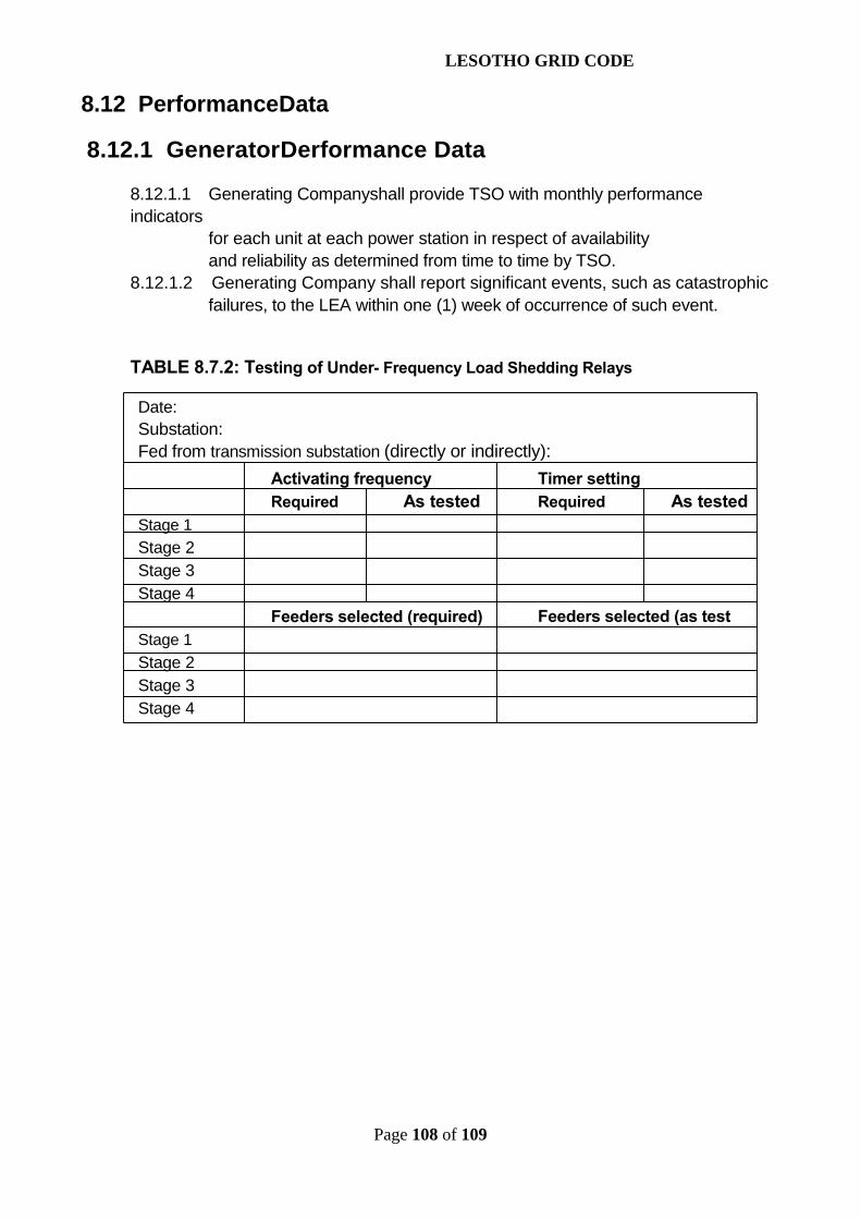
LESOTHO GRID CODE
Page 108 of 109
8.12 PerformanceData
8.12.1 GeneratorDerformance Data
8.12.1.1 Generating Companyshall provide TSO with monthly performanceindicators
for each unit at each power station in respect of availabilityand reliability as determined from time to time by TSO.
8.12.1.2 Generating Company shall report significant events, such as catastrophicfailures, to the LEA within one (1) week of occurrence of such event.
TABLE 8.7.2: Testing of Under- Frequency Load Shedding Relays
Date:Substation:Fed from transmission substation (directly or indirectly):
Activating frequencyRequired As tested
Stage 1Stage 2Stage 3Stage 4
Feeders selected (required)Stage 1Stage 2Stage 3Stage 4
Timer settingRequired As tested
Feeders selected (as test

LESOTHO GRID CODE
Page 109 of 109