transient-fault robust systems exploiting quasi-delay
TRANSCRIPT

HAL Id: tel-00541344https://tel.archives-ouvertes.fr/tel-00541344
Submitted on 30 Nov 2010
HAL is a multi-disciplinary open accessarchive for the deposit and dissemination of sci-entific research documents, whether they are pub-lished or not. The documents may come fromteaching and research institutions in France orabroad, or from public or private research centers.
L’archive ouverte pluridisciplinaire HAL, estdestinée au dépôt et à la diffusion de documentsscientifiques de niveau recherche, publiés ou non,émanant des établissements d’enseignement et derecherche français ou étrangers, des laboratoirespublics ou privés.
Transient-Fault Robust Systems Exploiting Quasi-DelayInsensitive Asynchronous Circuits
Rodrigo Possamai Bastos
To cite this version:Rodrigo Possamai Bastos. Transient-Fault Robust Systems Exploiting Quasi-Delay Insensitive Asyn-chronous Circuits. Micro and nanotechnologies/Microelectronics. Institut National Polytechnique deGrenoble - INPG, 2010. English. �tel-00541344�

UNIVERSITE DE GRENOBLE INSTITUT POLYTECHNIQUE DE GRENOBLE
N° attribué par la bibliothèque |__|__|__|__|__|__|__|__|__|__|
T H E S E E N CO T U T E L L E I N T E RNA T IONA L E
pour obtenir le grade de
DOCTEUR DE L’Université de Grenoble délivré par l’Institut polytechnique de Grenoble
et de l’Université Fédérale du Rio Grande do Sul
Spécialité : Micro et Nano Electronique
préparée au laboratoire TIMA (France)
dans le cadre de l’Ecole Doctorale Electronique, Electrotechnique, Automatique et Traitement du Signal
et aux laboratoires de l’Instituto de Informática (Brésil)
dans le cadre du Programa de Pós-Graduação em Microeletrônica
présentée et soutenue publiquement
par
Rodrigo POSSAMAI BASTOS
à Grenoble, le 9 Juillet 2010
Transient-Fault Robust Systems Exploiting Quasi-Delay Insensitive Asynchronous Circuits
Directeurs de thèse : Marc RENAUDIN (France), Ricardo REIS (Brésil) Co-directeurs de thèse : Gilles SICARD (France) et Fernanda KASTENSMIDT (Brésil)
JURY
M. Skandar BASROUR , Président M. Christian PIGUET , Rapporteur M. Matteo SONZA REORDA , Rapporteur M. Marc RENAUDIN , Directeur de thèse M. Ricardo REIS , Directeur de thèse M. Gilles SICARD , Co-directeur de thèse M. Gustavo WILKE , Examinateur


To my parents Melita and Fernando, my sister Fernanda,
and my aunt Elba.


CONTENTS
LIST OF ABBREVIATIONS ............................. .................................................. 7
LIST OF FIGURES ............................................................................................. 9
LIST OF TABLES .................................... ........................................................ 11
ABSTRACT .......................................... ............................................................ 13
RÉSUMÉ .......................................................................................................... 15
1 INTRODUCTION ......................................................................................... 17
2 ASYNCHRONOUS CIRCUITS ................................................................... 19
2.1 Classes of Asynchronous Circuits ...................................................................... 22
2.2 Quasi-Delay Insensitive Asynchronous Circuits ............................................... 24
2.2.1 Communication Protocol .................................................................................... 25 2.2.2 Data Codification ................................................................................................ 26 2.2.3 Logic Synthesis ................................................................................................... 28 2.3 Conclusions ........................................................................................................... 30
3 TRANSIENT-FAULT EFFECTS ON INTEGRATED CIRCUITS .... ............. 33
3.1 Transient Faults Induced by Environmental Perturbations ........................... 34
3.2 Types of Transient-Fault Effects ........................................................................ 35
3.2.1 Harmful Effects of Transient Faults on Synchronous Circuits ........................... 36
3.2.2 Harmful Effects of Transient Faults on QDI Asynchronous Circuits................. 37
3.2.3 Harmless Effects of Transient Faults .................................................................. 37
3.2.4 Failures: the Effects of Soft Errors ..................................................................... 38 3.2.5 Harmful Effects of Multiple-Transient Faults .................................................... 39
3.2.6 Harmful Effects of Long-Duration Transient Faults .......................................... 39
3.3 Conclusions ........................................................................................................... 39
4 EVALUATING TRANSIENT-FAULT EFFECTS AT LOGICAL LEVEL ...... 41
4.1 Method for Logical-Level Evaluation of Transient-Fault Effects ................... 42 4.1.1 Modelling the Transient-Fault Effects ................................................................ 43
4.1.2 Dynamic of Fault-Injection Simulations ............................................................. 44
4.1.3 Evaluation Metrics .............................................................................................. 46 4.1.4 Reducing the Total Number of Simulations ....................................................... 48
4.1.5 The Method on Case-Study Circuits ................................................................... 48
4.2 Conclusions ........................................................................................................... 53

6
5 ASYNCHRONOUS CIRCUITS AS ALTERNATIVE FOR MITIGATION OF LONG-DURATION TRANSIENT FAULTS IN DEEP-SUBMICRON TECHNOLOGIES ............................................................................................. 55
5.1 Natural Detection of Failures .............................................................................. 56 5.1.1 Ability of QDI Asynchronous Systems .............................................................. 57
5.1.2 Inability of Synchronous Systems ...................................................................... 58
5.2 Mitigation of Multiple-Transient Faults ............................................................ 58
5.3 Mitigation of Long-Duration Transient Faults ................................................. 59
5.4 A Case-Study Analysis ......................................................................................... 60 5.5 Conclusions ........................................................................................................... 61
6 TECHNIQUES FOR TRANSIENT-FAULT MITIGATION ......... ................... 63
6.1 Techniques at Logical and RT Abstraction Levels ........................................... 64
6.1.1 Classic Spatial Redundancies ............................................................................. 64 6.1.2 Temporal Redundancies ..................................................................................... 65 6.1.3 Spatial Redundancies by Gate Duplication ........................................................ 67
6.1.4 Spatial Redundancies by Codification ................................................................ 68
6.1.5 Techniques Dedicated to QDI Asynchronous Circuits ....................................... 68
6.2 Techniques at Electrical Abstraction Level ....................................................... 70
6.2.1 Spatial Redundancies by Transistors .................................................................. 71
6.2.2 Robust Memory Cells ......................................................................................... 72 6.3 Costs of Mitigation Techniques at Different Abstraction Levels .................... 73 6.4 Conclusions ........................................................................................................... 74
7 EVALUATING TRANSIENT-FAULT EFFECTS ON C-ELEMENT’S IMPLEMENTATIONS ................................... .................................................... 77
7.1 Traditional C-element’s Implementations ......................................................... 78
7.2 Method for Electrical-Level Evaluation of Transient-Fault Effects ............... 79 7.2.1 Modelling the Transient Faults ........................................................................... 79 7.2.2 Situations of Transient-Fault Vulnerability ........................................................ 80
7.2.3 Perturbation Charge of a Circuit Node ............................................................... 81
7.3 Making Transient-Fault Robust the C-element ................................................ 82
7.4 Evaluations of the C-element’s Implementations ............................................. 84
7.4.1 Simulation Experiments ...................................................................................... 84 7.4.2 Simulation Results and Evaluations ................................................................... 85
7.5 Conclusions ........................................................................................................... 90
8 CONCLUSIONS AND FUTURE WORKS ...................... ............................. 91
AUTHOR’S REFERENCES ............................... .............................................. 95
REFERENCES ................................................................................................. 99
APPENDIX A SISTEMAS ROBUSTOS A FALHAS TRANSIENTES EXPLORANDO CIRCUITOS ASSÍNCRONOS QUASE-INSENSÍVEIS AOS ATRASOS ........................................... ........................................................... 114
APPENDIX B SYSTEMES ROBUSTES AUX FAUTES TRANSITOIRE S EXPLOITANT LA LOGIQUE ASYNCHRONE QUASI-INSENSIBLE A UX DELAIS ............................................ .............................................................. 127
LIST OF ABBREVIATIONS
ASIC Application Specific Integrated Circuit
CAD Computer-Aided Design
CMOS Complementary Metal-Oxide-Semiconductor
CPU Central Processor Unit
CPO Circuit’s Primary Output
CWSP Code Word State Preserving
DES Data Encryption Standard
DIMS Delay-Insensitive Minterm Synthesis
DNA Deoxyribonucleic Acid
dSE Direct Soft Error
DWC Duplication with Comparison
EDA Electronic Design Automation
EDAC Error Detection and Correction
EEATS Electronique, Electrotechnique, Automatique & Traitement du Signal
EMI Electromagnetic Interference
FDN Failure Detectable Naturally
FPGA Field Programmable Gate Array
FNN Failure Non-detectable Naturally
FTN Faults Tolerated Naturally
HC Hamming Code
HCMOS High-density Complementary Metal-Oxide-Semiconductor
HDL Hardware Description Language
IC Integrated Circuit
INPG Institut National Polytechnique de Grenoble
iSE Indirect Soft Error
LDT Long-Duration Transient
MBU Multiple-Bit Upset

8
MDD Multi-valued Decision Diagram
MOSFET Metal-Oxide-Semiconductor Field-Effect Transistor
NOC Network-on-Chip
PDA Personal Digital Assistant
PGMicro Pós-Graduação em Microeletrônica
PPGC Programa de Pós-Graduação em Computação
QDI Quasi-Delay Insensitive
RAM Random Access Memory
RFID Radio Frequency Identification
ROM Read Only Memory
RT Register Transfer
SDF Standard Delay Format
SE Soft Error
SEO Signal of End Operation
SEE Single Event Effect
SER Soft Error Rate
SET Single-Event Transient
SEU Single Event Upset
SOC System-on-Chip
SOI Silicon-on-Insulator
SRAM Static Random Access Memory
TIMA Laboratoire de Techniques de l’Informatique et de la Microélectronique pour l’Architecture des systèmes intégrés
TR Time Redundancy
TMR Triple Modular Redundancy
UFRGS Universidade Federal do Rio Grande do Sul
VHDL VHSIC Hardware Description Language
VHSIC Very High Speed Integrated Circuit
VLSI Very Large Scale Integration
LIST OF FIGURES
Figure 2.1: The different classes of circuits in accord with the logic redundancy and the number of timing assumptions ....................................................................................... 23 Figure 2.2: Communication between stages of a QDI asynchronous system ................ 25
Figure 2.3: Four-phase protocol for a communication between stages .......................... 26
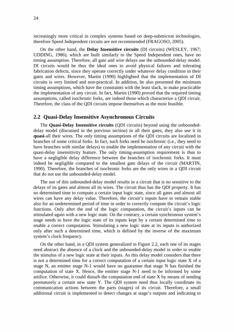
Figure 2.4: Dual-rail data codification by three states .................................................... 27
Figure 2.5: A structure of a QDI system by analogy to a synchronous system ............. 28
Figure 2.6: Function of a 2-input C-element gate .......................................................... 28
Figure 2.7: MDD-based logic synthesis of a delay-insensitive dual-rail XOR function for the four-phase protocol ............................................................................................. 29 Figure 2.8: A QDI system operating through the four-phase protocol ........................... 30
Figure 3.1: A generic hardware module to represent either a synchronous systems or a QDI asynchronous .......................................................................................................... 36 Figure 4.1: Simulation scheme of a SET on an IC-design netlist .................................. 43
Figure 4.2: Modelling of a SET fault on a netlist’s wire ................................................ 43
Figure 4.3: Fault-injection simulations into a synchronous circuit ................................ 44
Figure 4.4: Fault-injection simulations into a QDI asynchronous circuit with different logic values at its C-element’s inputs ............................................................................. 44 Figure 4.5: Fault-injection simulations into a QDI asynchronous circuit with equal logic values at its C-element’s inputs ...................................................................................... 44 Figure 4.6: Simulation methodology for injection of SETs ........................................... 45
Figure 4.7: The total number of injected transient faults and their consequences ......... 47
Figure 4.8: Estimating a methodology’s evaluation metric (Sensitivity) ....................... 49 Figure 4.9: Circuits’ Sensitivities in terms of the ratio des_sync / des_async................ 50 Figure 4.10: System-robustness percentages .................................................................. 51
Figure 4.11: Circuits’ Sensitivities by considering between des_async and des_sync an area factor of 2 and computation time factor of 1 .......................................................... 52 Figure 5.1: Transient-fault width vs. clock’s cycle time scaling (LISBOA, 2009) ........ 56 Figure 5.2: A case study on a DES crypto-processor: system’s ability for detection in function of transient fault durations................................................................................ 60 Figure 5.3: The stronger natural ability of a QDI asynchronous system for mitigation of LDT faults in deep-submicron technologies .................................................................. 61 Figure 6.1: TMR scheme applied on a 1-bit register ...................................................... 65
Figure 6.2: TR+CWSP scheme applied on a 1-bit register ............................................ 66
Figure 6.3: TR+CWSP scheme working on a 1-bit register ........................................... 67
Figure 6.4: CWSP elements at logical abstraction level (NICOLAIDIS, 1999) ............ 67 Figure 6.5: Duplication-based technique for computational logic of a QDI system (MONNET, 2005-b) ....................................................................................................... 70

10
Figure 6.6: Synchronization Technique for two bits of a data word in a QDI system (MONNET, 2005-b) ....................................................................................................... 70 Figure 6.7: CWSP elements at electrical abstraction level (NICOLAIDIS, 1999) ........ 71 Figure 6.8: A robust latch (OMAÑA, 2007) .................................................................. 72
Figure 6.9: Costs of mitigation techniques at different abstraction levels ..................... 73
Figure 6.10: Area costs of traditional mitigation techniques in function of the memory-core area ratio ................................................................................................................. 74
Figure 7.1: The traditional C-element’s implementations .............................................. 78
Figure 7.2: Modelling the perturbation-induced transient current ISET that temporally discharges (off-state NMOS case) or charges (off-state PMOS case) the node out ....... 80
Figure 7.3: Nodes’ logic states of the weak-feedback C-element version under a situation of transient-fault vulnerability ......................................................................... 80 Figure 7.4: The explicit-capacitor version of a weak-feedback C-element .................... 83
Figure 7.5: GPCV increases vs. penalties in delay of C-element versions ..................... 86
Figure 7.6: GPCV increases vs. power-consumption overheads ..................................... 87
Figure 7.7: GPCV increases vs. diffusion-area overheads .............................................. 88
Figure 7.8: GPCV increases vs. C-element implementation costs .................................. 89

LIST OF TABLES
Table 3.1: Possible primary outputs of a module perturbed by transient faults ............. 39
Table 3.2: Summary of transient-fault effects on synchronous and QDI asynchronous circuits ............................................................................................................................ 40
Table 5.1: Possible CPOs of a system perturbed by transient faults .............................. 57
Table 7.1: Situations of transient-fault vulnerabilities on the traditional C-element’s versions ........................................................................................................................... 81
Table 7.2: Diffusion widths WN4, WP4, WNI, WPI, WNE, WPE WNC, and WPC of the NMOS and PMOS transistors in robust C-element cells ............................................... 83
Tabela 1: Possiveis CPOs de um sistema perturbado por falhas transientes ................ 119
Tableau 1: Possibles CPOs d'un système perturbé par fautes transitoires.................... 132


ABSTRACT
Recent deep-submicron technology-based ICs are significantly more vulnerable to transient faults. The arisen errors are thus also more critical than they have ever been before. This thesis presents a further novel benefit of the Quasi-Delay Insensitive (QDI) asynchronous circuits in terms of reliability: their strong natural ability to mitigate long-duration transient faults that are severe in modern synchronous circuits. A methodology to evaluate comparatively the transient-fault effects on synchronous and QDI asynchronous circuits is presented. Furthermore, a method to obtain the transient-fault mitigation ability of the QDI circuits’ memory elements (i.e., the C-elements) is also proposed. Finally, mitigation techniques are suggested to increase even more the C-elements’ transient-fault attenuation, and thus also the QDI asynchronous systems’ robustness.
Keywords: Design of robust or fault-tolerant systems, QDI asynchronous circuits, transient faults, soft errors, evaluation of transient-fault effects.


Systèmes Robustes aux Fautes Transitoires Exploitant la Logique Asynchrone Quasi-Insensible aux Délais
RESUME
Les technologies nanoélectroniques récentes font que les circuits intégrés deviennent de plus en plus vulnérables aux fautes transitoires. Les erreurs engendrées sont aussi plus critiques que jamais auparavant. Cette thèse présente un nouvel avantage en termes de fiabilité des circuits asynchrones quasi-insensibles aux délais (QDI) : Leurs fortes résistances naturelles aux fautes transitoires de longue durée qui sont graves pour les circuits synchrones actuels. Une méthodologie pour évaluer comparativement les effets des fautes transitoires sur les circuits synchrones et asynchrones QDI est présentée. En outre, une méthode pour obtenir la résistance aux fautes transitoires des éléments mémorisants spécifiques aux circuits QDI (les portes de Muller) est également proposée. Enfin, des techniques de tolérance ont été étudiées pour augmenter encore plus la robustesse des portes de Muller aux fautes transitoires, et donc aussi la robustesse des systèmes asynchrones QDI.
Mots clés: Conception de systèmes robustes ou tolérants aux fautes, circuits asynchrones QDI, fautes transitoires, soft errors, évaluation des effets aux fautes transitoires.


1 INTRODUCTION
The IC fabrication technology’s evolution has allowed in last years the use of nanometer scales to design semiconductor devices. Deeper-submicron technologies enable thus the development of sophisticated electronic systems in small scale, high density, high performance, and low power consumption.
On the other hand, the close proximity to the physical limits of the semiconductors and the high complexity of such deep-submicron technology-based designs impose considerable challenges to the IC reliability. The circuits indeed suffer harmful effects that in older technologies were practically negligible.
There are many challenges imposed by deep-submicron technologies to the circuit reliability. Several types of faults can thus occur in a circuit given its larger vulnerability. Today nanoelectronic circuits are indeed more sensitive to variations of fabrication process as well as environmental factors like temperature, radiations, and electrical noise. IC-based systems are so more vulnerable to two effects of such variations: timing alterations of the circuit delays and transient voltage modifications.
Such effects, in terms of voltage transients and delay variations, have motivated many researches due to the severity of their consequences for the systems. In fact, these effects, known respectively as transient faults and delay faults, can provoke errors in circuit’s functional operations. If propagated, theses errors can lead the circuit to produce inconsistent results at its primary outputs, and so making a system’s failure scenario.
Normally, delay faults are arisen from fabrication process variations, however they can also be induced by environmental factors. On the contrary, transient faults are generated due to environmental or intentional-perturbation events. A single perturbation event on an IC can produce a transient fault so-called as single-event transient (SET). Moreover, there are lower-probability cases in which multiple-perturbation events or even a single event can create multiple-transient faults. The worst transient-fault effects on ICs are memory-bit flips that are non-permanent errors in memory cells named as soft errors (SEs). If transient faults accomplish upsetting various memory cell’s bits, the phenomenon is thus known as multiple-bit upset (MBU).
The transient and delay faults have even more severe effects in deeper-submicron technologies where the circuit’s delays are inherently shorter. In these technologies, it is possible that fault’s durations are comparable or even longer than the clock cycle’s periods. In addition, most of the existing mitigation techniques require very-high power, performance, and area overheads to deal with such long-duration transient (LDT) faults, hence new solutions to protect the circuits are necessary (LISBOA, 2007-a). LDT faults

18
have clearly a much higher probability of not being masked, and therefore they also stand a greater chance of producing a system’s failure.
In fact, such a higher error probability is due to the limitation of the clock period that is thus fundamental for the severity of transient and delay faults. On the other hand, the clock is a particularity of the traditional synchronous circuits which suffer thus much more with the worse LDT consequences than clockless circuits. Hence, designing circuits that are not controlled by a global clock but only by their internal data flow can result in systems that are more robust against such LDT faults. It is the case of the asynchronous circuits, and specially their most important class: the Quasi-Delay Insensitive (QDI) circuits.
Essentially, QDI circuits are composed of C-elements, so-called Muller gates. Such an element, which has a dual-behavior, works either as a buffer or as a memory cell. These special gates ensure the QDI property and permit the synchronization between circuit’s stages, where a handshaking protocol is applied by a multi-rail data path.
The multi-rail data codification and the asynchronous handshaking communication of QDI systems make the detection and correction of errors easier (MONNET, 2007-a). The absence of a clock tree allows them to emit less electromagnetic interference (PANYASAK, 2004), and makes them more secure against malicious power analysis (BOUESSE, 2005). Moreover, such a clockless property also leads to increased energy savings (RIOS, 2008), and achieving high performance at the expense of using less than twice larger area than their synchronous counterparts. A QDI circuit is also inherently robust against delay faults on most of its paths due to its natural QDI property (LAFRIEDA; MANORAR, 2004). In addition, its C-elements are fundamental to implement more robust systems. In fact, even in synchronous systems, C-elements are often used to filter transient faults, and so protecting the circuits against SEs (NICOLAIDIS, 1999; MITRA et al, 2005; FAZELI et al, 2007). Then, QDI systems’ C-elements improve the circuit’s ability for masking transient faults (MONNET, 2007-a). Such inherent characteristics of QDI asynchronous designs ensure a high systems’ reliability without implementing costly hardware-based mitigation mechanisms which in synchronous designs are practically indispensable to obtain similar immunity level.
As QDI asynchronous circuits are undeniably quite robust against delay faults, the goal of this thesis was exploiting such a class of circuits in order to obtain more transient-fault robust systems.
In this thesis, chapter 2 shows the benefits and features of the QDI asynchronous systems. Chapter 3 outlines the different transient-fault effects on ICs. In Chapter 4, a novel method is proposed to evaluate at logical level the transient-fault effects as on synchronous circuits as on QDI asynchronous circuits. Chapter 5 presents and discusses a new QDI asynchronous systems’ benefit in comparison with synchronous systems: their better natural ability for mitigation of LDT faults in deep-submicron technologies. In chapter 6, hardware-based transient-fault mitigation techniques and their costs to protect synchronous circuits at different abstraction levels are discussed. Furthermore, chapter 7 evaluates innovatively the transient-fault effects on traditional C-element’s implementations and also presents for the first time the best C-element’s options to further improve the QDI asynchronous systems’ robustness. Finally, chapter 8 highlights the main contributions of this thesis as well as the ideas to be discussed in future works.

2 ASYNCHRONOUS CIRCUITS
Even nowadays the largest part of ICs in electronics equipments are based on an oscillator to start, process, and finalize all of their operations. Such electronics systems are synchronous circuits at a frequency of a signal well determined to reach all circuit parts. However, in the last years, there are already systems in which their different internal circuits operate without the need of the pace of a global clock. These circuits then so-called asynchronous or clockless use their own data flow to locally govern the computation and communication between parts of the system.
The asynchronous communication activity between circuit blocks, and even among systems with their environments, had a significant increase (BRZOZOWKI; SEGER 1995). Indeed, the technological evolutions and their more complex ICs have required asynchronous activities to face with design challenges. Synchronous blocks which operate on different frequencies need asynchronous interfaces to efficiently exchange data (SUTHERLAND, EBERGEN, 2002). In the last years, the use of asynchronous approaches has also been targeted for electronics applications or embedded systems. Asynchronous systems are thus mostly applied to achieve low power consumption, reliability, robustness, and security. Then, applications such as smart cards, RFIDs, pagers, PDAs, power management chips, electronics for automation and avionics, sensor networks, cell phones, metering, medical, mobile, and battery-powered devices are very feasible. In addition, high-performance applications like processors for simulation, audio, video, images, signals, graphics, servers, and workstations may also be designed by asynchronous logic (GEER, 2005; TIEMPO, 2009).
Asynchronous systems are not only applications for ICs. Synthetic biology uses engineering principles to design genetic circuits. Such biological circuits constructed from DNA (deoxyribonucleic acid) are inserted into bacteria to perform various tasks (NGUYEN et al, 2007). As there is not a global clock, genetic circuits are inherently asynchronous. Thus, asynchronous design techniques are also applied for many applications of the synthetic biology, which contributes directly, for instance, in the production of drugs to combat malaria (NGUYEN et al, 2007).
In fact, all digital systems, essentially, can be viewed as asynchronous (BRZOZOWKI; SEGER 1995). Some fundamental concepts related to asynchronous circuits support the operational characteristics of the synchronous (FLETCHER, 1980). A synchronous circuit is designed based on rules of a particular project and operated under special assumptions of its environment (BRZOZOWKI; SEGER 1995). Its combinational circuits process their logic functions asynchronously within a clock period. In addition, its hearts, the flip-flops, are structurally asynchronous sequential machines that operate within the time conditions of set-up and hold. Several other

20
asynchronous machines, such as, latches and Muller C-elements, are also components for the design of synchronous systems.
The concepts of asynchronous circuits are suggested since the middle of the last century when there was the development of the first asynchronous machines (FLETCHER, 1980). However, synchronous approaches prevailed in the microelectronics industry due to the simplicity in the design implementation of the control and logic circuit (FRAGOSO, 2005). Such a dominion nowadays is accomplished by the maturity of commercial CAD tools dedicated to synchronous. Although synchronous methods could be adapted for asynchronous (KONDRATYEV; LWIN, 2002), they are optimized for synchronous. There is, therefore, a larger complexity for the implementation of asynchronous designs by using such synchronous-dedicated tools. Moreover, the resulting asynchronous circuits are poorly optimized. In fact, these tools are not prepared to implement a local organization for asynchronous communications between circuit blocks. Then, implementations of asynchronous protocols are not optimized resulting thus in high overheads in terms of area and total computation time.
On the other hand, a coordination of asynchronous actions also determines additional hardware mechanisms and, therefore, costs in terms of area. Indeed, even using an efficient synthesis method for asynchronous designs, the area of an asynchronous system reaches the order of twice the size of an equivalent synchronous system. However, this is practically the only cost paid to obtain the many inherent advantages of an asynchronous system. The absence of a fixed rhythm of a global clock allows several important benefits that are discussed in the following paragraphs (SUTHERLAND, EBERGEN, 2002; FRAGOSO, 2005; SPARSO, 2006; FLETCHER, 1980; HAUCK, 1995; BRZOZOWKI; SEGER 1995):
• Sutherland and Ebergen (2002) observe that the efforts required to coordinate asynchronous actions are small. An asynchronous system indeed may, on average, be faster than a synchronous, especially in irregular IC designs in which slower actions are infrequent. In fact, the data paths of asynchronous circuits operate in the pace of their gate and wire delays. Thus, operations more complex and less frequent take more time than average, and simple and frequent ones take less. On the other hand, synchronous systems are always in the pace of the longest circuit path. In addition, a margin to cope with variations of the clock (jitter and skew), and manufacturing and environmental irregularities must be also considered (GEER, 2005). Therefore, simple tasks in synchronous circuits run slower to follow the pace of the more complex ones;
• In clocked systems, the delay differences between data paths of their circuits generate the so-called static hazards (FLETCHER, 1980), which are tolerated by using a global clock. Otherwise, such a kind of spurious switching is not allowed in asynchronous design. By nature, indeed, asynchronous systems have no static hazards. Therefore, dynamic power is not wasted. In addition, as there is not a clock, a clock-distribution circuit is not required. Consequently, lower power consumptions (GAGELDONK, 1998) are feasible. In fact, nowadays complex synchronous chips, like microprocessors, have clock-tree circuits that represent a good part of the system’s area (SUTHERLAND, EBERGEN, 2002). About 30% of the power consumed by such chips is due to the clock and its distribution circuit. Furthermore, as the clock is always working, the chip heats even though
21
it is not doing anything useful. Clockless systems, otherwise, allow easily disable blocks of the circuit to reduce the power consumption;
• The need nowadays to distribute uniformly the clock signal in all parts of the chips, which are faster and denser, has required synchronous designs even more sophisticated in order to avoid different latching times within the clock-skew problem. Given such a technological trend, asynchronous approaches arise as an interesting alternative to avoid elaborate clock-tree designs in complex circuits;
• Synchronization by a clock also requires more careful designs with signals from a system’s asynchronous interface. An inadequate sampling of such signals can put the synchronous circuit indefinitely in meta-stable states (FLETCHER, 1980; HAUCK, 1995; BRZOZOWKI; SEGER 1995; MYERS, 2001). In contrast, asynchronous systems by nature can wait the interfaces to meet stable conditions in order to start a correct computation, and thus avoiding the metastability phenomenon;
• The clock also limits the modularity of a synchronous system, which requires special interfaces to perform communications with other systems of different operation frequencies (SUTHERLAND, EBERGEN, 2002; FRAGOSO, 2005). Asynchronous modules are much more flexible because their circuits do not have to share a common rhythm, therefore, they easily allow designs of SOCs and NOCs;
• The absence of a clock’s fixed rhythm allows also lower emissions of electromagnetic interferences (EMI) (SUTHERLAND, EBERGEN, 2002; PANYASAK, 2004). In contrast, synchronous systems emit stronger electromagnetic signals at its clock frequency and harmonics. Besides being able to produce internal noise in its own circuit, such signals can also interfere with televisions, cellular phones, aircraft navigation systems, and any electronics equipment operating at the same frequency band;
• More recently, asynchronous systems, especially the Quasi-Delay Insensitive class (QDI Circuits), are suggested as a qualified alternative to design robust and secure circuits. This topic is discussed at greater length in the following sections of this chapter.
Given such many advantages, asynchronous applications certainly will evolve even more in the IC market, especially when the various methods optimized for the asynchronous design, like those in (VIVET, 2001; RIGAUD, 2002; MAURINE et al, 2003; DINH-DUC, 2003; FOLCO et al, 2005; FRAGOSO, 2005; BALSA, 2009; TIEMPO, 2009), conquer more popular commercial dimensions. However, these asynchronous qualities already encourage several efficient commercial applications which perhaps still are little known by the scientific community and industry.
Asynchronous ICs indeed are already in commercial mass production (SUTHERLAND, EBERGEN, 2002). The electronics company Sharp already released asynchronous media chips devoted to edit graphics, video, and audio. Asynchronous microcontrollers are used in pagers sold by Philips Electronics. Some synchronous processors from Sun Microsystems include asynchronous blocks to organize information from memory chips. Other hybrid applications are proposed but based on the idea of globally asynchronous and locally synchronous designs (CHAPIRO, 1984;
22
IYER; MARCULESCU, 2002; TEEHAN, 2007). The Handshake Solutions and ARM companies developed asynchronous cores for devices such as smart cards, consumer electronics, and automotive applications (GEER, 2005). In addition, the Fulcrum Microsystems offers asynchronous chips of high performance for networks, storage devices, and embedded systems. The Theseus Logic company developed a low-power and low-noise asynchronous version of a Freescale’s 8-bit microcontroller. It is for signal-processing or battery-powered applications. Moreover, such a company with a medical-equipment provider, the Medtronic, also produced asynchronous chips for defibrillators and pacemakers. The French company Tiempo presents its asynchronous-based solutions for applications of smart cards, RFIDs, cellular phones, mobile handsets, power management, automobile, avionics, and medical systems. Tiempo’s products include IP cores of microcontrollers, microprocessors, and crypto-processors, as well as an asynchronous-dedicated EDA tool (TIEMPO, 2009). Besides these and other companies, there are several asynchronous-dedicated research groups at educational institutions like the California Institute of Technology, the University of Manchester, the University of Tokyo, and the TIMA Laboratory in Grenoble.
According to the aim of this work, the following sections present the main characteristics of this important asynchronous option to design, especially, low-power, reliable, robust, and secure circuits.
2.1 Classes of Asynchronous Circuits An asynchronous system has, as a natural feature, a well-coordinated activity of its
data switching (KONDRATYEV; LWIN, 2002). The computation flow is not modelled with the aid of a clock but with the implementation of logic redundancy in parts of the circuit. It thus prevents spurious switching, the hazards, which arise from the delay differences in the gates and wires of the system. On the other hand, the design of a synchronous system does not require, within a clock period, an exact timing sequence coordination of the circuit’s switching activity. The design implementation, therefore, requires less redundancy.
In the past decades, these features related to the lower design complexity and smaller circuit area were very important for the synchronous design achieving today such a maturity. However, given the current technological trends that require more robust systems, the larger redundancy in asynchronous have made such circuits very attractive.
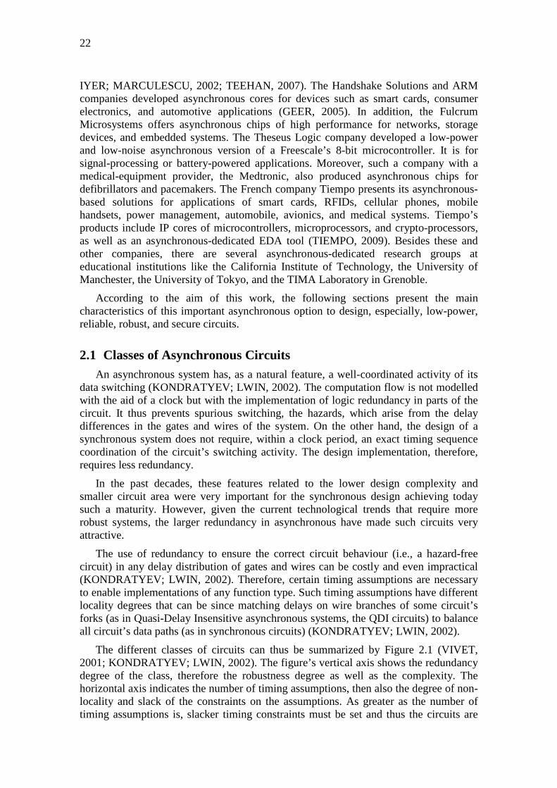
The use of redundancy to ensure the correct circuit behaviour (i.e., a hazard-free circuit) in any delay distribution of gates and wires can be costly and even impractical (KONDRATYEV; LWIN, 2002). Therefore, certain timing assumptions are necessary to enable implementations of any function type. Such timing assumptions have different locality degrees that can be since matching delays on wire branches of some circuit’s forks (as in Quasi-Delay Insensitive asynchronous systems, the QDI circuits) to balance all circuit’s data paths (as in synchronous circuits) (KONDRATYEV; LWIN, 2002).
The different classes of circuits can thus be summarized by Figure 2.1 (VIVET, 2001; KONDRATYEV; LWIN, 2002). The figure’s vertical axis shows the redundancy degree of the class, therefore the robustness degree as well as the complexity. The horizontal axis indicates the number of timing assumptions, then also the degree of non-locality and slack of the constraints on the assumptions. As greater as the number of timing assumptions is, slacker timing constraints must be set and thus the circuits are

23
simpler (FRAGOSO, 2005). However, they are less robust, less modular, and the timing assumptions are more difficult to meet (KONDRATYEV; LWIN, 2002).
Figure 2.1: The different classes of circuits in accord with the logic redundancy and the number of timing assumptions
The Huffman circuits (HUFFMAN, 1954-a; HUFFMAN, 1954-b), which are also known as asynchronous sequential machines, are the origin of the asynchronous systems and therefore they well represent their fundamental mode. Such circuits consist of a set of combinational gates, which compute the next state and circuit outputs, and a set of feedback lines, which store the circuit states (ALMUKHAIZIM, 2008). Their inputs must remain at a steady state for a minimum time that ensures the circuit stabilization. The classic examples of Huffman circuits are the flip-flops, which must conserve the time of set-up and hold to stabilize their outputs. Other asynchronous sequential machines more complex are feasible, but they will be even more sensitive to the delays of their gates and wires. Therefore, they are sensitive to delay variations beyond the limits set by the designer, because they use a model known as bounded delay. The circuits will be thus more sensitive to physical failures and more vulnerable to fabrication defects (defined in chapter 3). The same bounded delay is also used in synchronous circuits, so they are also subject to these vulnerabilities.
The Micropipeline circuits (SUTHERLAND, 1989) are asynchronous architectures that, as the pipelines of synchronous approaches, compute and store data. The global clock is replaced by a local-synchronization structure based on handshake. It is used to control the elastic data pipeline in the circuit stages (FRAGOSO, 2005). The control circuit operates independently of its gate and wires delays, so it uses an unbounded-delay model. It means that no upper limit to the values of its delays is needed or established, since there is an asynchronous communication by handshake between its stages (HAUCK, 1995). Furthermore, the bounded-delay model is also used on the Micropipeline circuits, but only on the architecture’s data path to circumvent the hazard problem in its computation logic. Micropipeline circuits are thus also subject to those vulnerabilities discussed in last paragraph for Huffman circuits.
The Speed Independent circuits (MILLER, 1961) use the unbounded-delay model on all their gates, but the delays of all their wires are simply negligible or assumed smaller than their smaller gate delays (HAUCK, 1995). Nowadays the wire delays are
Number of Timing Assumptions
Logi
c R
edun
danc
y Delay Insensitive
Quasi-Delay Insensitive
Speed Independent
MicropipelineHuffman
Synchronous
Number of Timing Assumptions
Logi
c R
edun
danc
y Delay Insensitive
Quasi-Delay Insensitive
Speed Independent
MicropipelineHuffman
Synchronous
24
increasingly more critical in complex systems based on deep-submicron technologies, therefore Speed Independent circuits are not recommended (FRAGOSO, 2005).
On the other hand, the Delay Insensitive circuits (DI circuits) (WESLEY, 1967; UDDING, 1986), which are built similarly to the Speed Independent ones, have no timing assumption. Therefore, all gate and wire delays use the unbounded-delay model. DI circuits would be thus the ideal ones to avoid physical failures and tolerating fabrication defects, since they operate correctly under whatever delay condition in their gates and wires. However, Martin (1990) highlighted that the implementation of DI circuits is very limited and non-practical. In addition, he also presented the minimum timing assumptions, which have the constraints with the least slack, to make practicable the implementation of any circuit. In fact, Martin (1990) proved that the required timing assumptions, called isochronic forks, are indeed those which characterize a QDI circuit. Therefore, the class of the QDI circuits impose themselves as the most feasible.
2.2 Quasi-Delay Insensitive Asynchronous Circuits The Quasi-Delay Insensitive circuits (QDI circuits) beyond using the unbounded-
delay model (discussed in the previous section) in all their gates, they also use it in quasi-all their wires. The only timing assumptions of the QDI circuits are localized in branches of some critical forks. In fact, such forks need be isochronic (i.e., they need to have branches with similar delays) to enable the implementation of any circuit with the quasi-delay insensitivity feature. The only timing-assumption requirement is thus to have a negligible delay difference between the branches of isochronic forks. It must indeed be negligible compared to the smallest gate delays of the circuit (MARTIN, 1990). Therefore, the branches of isochronic forks are the only wires in a QDI circuit that do not use the unbounded-delay model.
The use of this unbounded-delay model results in a circuit that is no sensitive to the delays of its gates and almost all its wires. The circuit thus has the QDI property. It has no determined time to compute a certain input logic state, since all gates and almost all wires can have any delay value. Therefore, the circuit’s inputs have to remain stable also for an undetermined period of time in order to correctly compute the circuit’s logic functions. Only after the end of the logic computation, the circuit’s inputs can be stimulated again with a new logic state. On the contrary, a certain synchronous system’s stage needs to have the logic state of its inputs kept by a certain determined time to enable a correct computation. Stimulating a new logic state at its inputs is authorized only after such a determined time, which is defined by the inverse of the maximum system’s clock frequency.
On the other hand, in a QDI system generalized in Figure 2.2, each one of its stages need abstract the absence of a clock and the unbounded-delay model in order to enable the stimulus of a new logic state at their inputs. As this delay model considers that there is not a determined time for a correct computation of a certain input logic state X of a stage N, an emitter stage N-1 would have no guarantee that stage N has finished the computation of state X. Hence, the emitter stage N-1 need to be informed by some artifice. Otherwise, it could disturb the computation end of state X by means of sending prematurely a certain new state Y. The QDI system need thus locally coordinate its communication actions between the parts (stages) of its circuit. Therefore, a small additional circuit is implemented to detect changes at stage’s outputs and indicating to

25
the emitter stage, by means of an acknowledgment signal, the computation end of a state X. Thus, the correct computation of a state X and a new state Y are achievable.
Figure 2.2: Communication between stages of a QDI asynchronous system
Such an acknowledgment signal to the emitter stage need be always consistent to ensure the QDI property of a system. Therefore, the circuit design of a QDI system’s stage need also ensure that
• no hazards occur on any stage’s logic and
• whatever logic state transition at stage’s inputs results in some logic state change at stage’s outputs.
Ensuring such conditions, eventual false acknowledgements to the emitter stage are avoided because there are no hazards. In fact, these conditions eliminate any stage’s input logic transition that does not generate logic state changes at stage’s outputs. Hence, the outputs of a receiver stage will not fail to acknowledge an input transition. It ensures, therefore, the feasibility to observe all possible input logic transitions of a receiver stage by means of its output transitions. Finally, it also ensures an accurate acknowledgement to the emitter stage that becomes enabled to send a new logic state to the receiver stage’s inputs. Evidently, it is ensured because any output logic transition of the receiver stage means, in theory, a correct computation of a logic state at its inputs. Consequently, only ensuring these conditions there will be a guarantee that the emitter stage will not stay without knowing about the computation end of the receiver stage.
To implement such conditions, three design mechanisms are used:
• a communication protocol between system’s stages that implements a handshake by request and acknowledgement to start a certain computation and indicating its end;
• a data codification that allows the stage to detect a computation request as well identifying its end; and
• circuits of the logic functions synthesized in a certain way that do not allow the hazard generation.
2.2.1 Communication Protocol
The communication between stages of a QDI system is organized by a protocol. It allows agreeing a handshake by request and acknowledgment to control the data flow and the computation. Therefore, any action produced by an emitter stage to modify the input logic state of a receiver stage is necessarily authorized before by the receiver stage’s outputs.
A traditional protocol uses two phases to achieve a cycle for computation of a certain logic state X and authorization of a new one Y. However, the protocol that is currently further used in QDI systems consists of four phases. This protocol guarantees a simpler implementation (FRAGOSO, 2005; MONNET, 2007-a) because the detection
Stage N-1 Data0N
Data1N
Stage N
AcknowledgementN AcknowledgementN+1
Data0N+1
Data1N+1
Data0N-1
Data1N-1
AcknowledgementN-1
Stage N-1 Data0N
Data1N
Stage N
AcknowledgementN AcknowledgementN+1
Data0N+1
Data1N+1
Data0N-1
Data1N-1
AcknowledgementN-1

26
of its phases is performed by logical level rather than transition events, as it is done in the two-phase protocol.
Figure 2.3 illustrates the four phases of such a protocol. In the first phase, Phase 1, valid data are detected at the inputs of the receiver stage N that computes and generates, by using its data outputs, a signal of acknowledgment at the computation end. In Phase 2, the acknowledgment is detected by the emitter stage N-1 that sends zero to all data inputs of the receiver stage N. Such returns to zero level are known as invalid data that are defined by a codification discussed in the next section. In Phase 3, the invalid data are detected by the receiver stage N that generates again the signal of acknowledgment. Finally, Phase 4, such an acknowledgment is detected by the emitter stage N-1 that is thus authorized to send new valid data to the inputs of the receiver stage N.
Figure 2.3: Four-phase protocol for a communication between stages
2.2.2 Data Codification
A QDI system’s stage detects the presence of new input data only by its own data switching. However, implementing such a mechanism requires necessarily a data codification based on more than one wire to represent a data bit, i.e., a multi-rail codification. The request to begin a new computation and the information of data validity can thus be included in its own data (FRAGOSO, 2005).
Otherwise, by implementing a codification that has only one wire per data bit (i.e., single rail), the use of a specific additional signal to characterize the request would be needed. In addition, the bounded-delay model would have to be used in the circuit’s data path to thus ensure an end of the data computation before the end of the request signal. In fact, a fixed delay in such a request signal would have to be defined for it goes along with the computation of the slowest circuit logic. Therefore, the circuit would not be a QDI, but a Micropipeline. Furthermore, in case of using a single-rail codification without the aid of any request signal, a new logic state equal to the current state at data inputs could not be detected without the implementation of a data packet. Moreover, interpreting the beginning of the packet would require a memory bank in each stage. In order to avoid the computation time in such a package interpretation, a data codification using more than one wire per data bit would make easier not only the implementation of the logic circuit responsible to identify a request but also the circuit for acknowledgment generation.
The minimum data codification, which is thus the most traditional one, uses two wires per data bit, i.e., it is the dual-rail codification. Based on two wires per data bit, four states of data codification are available (00, 01, 10, and 11) to express two logic values of a data bit (0 or 1) (MONNET, 2007-a).
Invalid DataReturn to 0
Valid Data
Valid Data Valid DataInvalid DataReturn to 0
Data Outputsof a Receptor Stage N
Acknowledgement Output of a Receptor Stage N ►
►
Valid DataInvalid DataReturn to 0
Data Inputsof a Receptor Stage N ► Invalid Data
Return to 0
Phase 1 Phase 2 Phase 3 Phase 4 Phase 1 Phase 2Phase 4Phase 3
Cycle X Cycle X+1Cycle X-1
27
For a two-phase protocol, the four states are used to ensure the codification of all possible transition events of a data bit (0=>0, 0=>1, 1=>0, and 1=>1) (FRAGOSO, 2005). The least significant bit’s value of a codification state expresses the logic value of the data. In addition, a new computation request is detected by the modification of the codification state’s parity (“codification state 00” => parity even, logic value 0; “state 01” => odd, value 1; “state 10” => odd, value 0; “state 11” => even, value 1). Owing to such particularities, the implementation of this protocol is more complex and less used.
For a four-phase protocol, only three states are required to code a valid-data logic value 0, another 1, and a return to zero defined as an invalid data. A fourth state is thus considered as forbidden or not used (FRAGOSO, 2005). This dual-rail data codification by three states is illustrated in Figure 2.4. This approach ensures that the transition from a certain state to another is always done by modifying only a single bit of the codification state (MONNET, 2007-a). Hazards, therefore, are not tolerated because any spurious switching could lead the circuit to an unwanted codification state. On the other hand, the generation of the acknowledgment signal can be easily implemented by a simple NOR gate monitoring the stage’s outputs.
Figure 2.4: Dual-rail data codification by three states
Even if the dual-rail codification is the most used in the design of QDI circuits, other codifications based on N wires to represent a data bit are also feasible. In case of dual rail, two wires (N=2) are thus used to represent a data bit. However, only one wire (M=1) must be equal to logic level 1 to code a logic value of a data bit. To implement a QDI circuit, any codification is possible for a data bit represented by N wire(s) at which M of such wire(s) must be equal to logic level 1 to code a logic value. Unfortunately, such codifications known as M-out-of-N increase the circuit design complexity.
Codifications M-out-of-N are redundant by nature, so they ensure a greater data bit robustness to voltage variations due to environmental or intentional perturbation events. For instance, by using codification 1-out-of-2 (dual rail), if one of the data bit wires erroneously switching to a complementary logic state (as from 00 to 01; 01=>00; 01=>11; 00=>10; 10=>00; and 10=>11), the chance of the resulting erroneous state being the forbidden state 11 is 2 / 6. Under correct circuit operation, this forbidden state will never be used, therefore it can be monitored by a simple AND gate as a form of error detection scheme. As the circuit has such a redundancy able to detect errors, it is thus also more robust.
00Invalid Data
01Valid Data
10Valid Data
11Forbidden
Error
State
State State
State
00Invalid Data
01Valid Data
10Valid Data
11Forbidden
Error
State
State State
State
28
2.2.3 Logic Synthesis
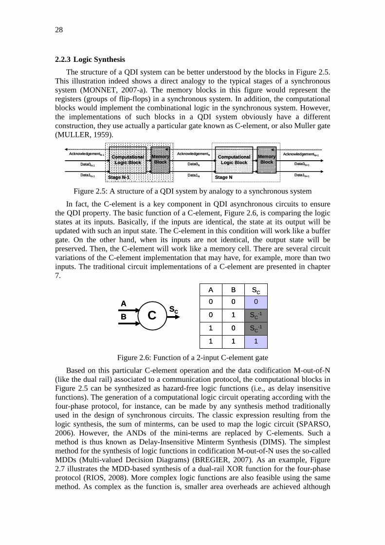
The structure of a QDI system can be better understood by the blocks in Figure 2.5. This illustration indeed shows a direct analogy to the typical stages of a synchronous system (MONNET, 2007-a). The memory blocks in this figure would represent the registers (groups of flip-flops) in a synchronous system. In addition, the computational blocks would implement the combinational logic in the synchronous system. However, the implementations of such blocks in a QDI system obviously have a different construction, they use actually a particular gate known as C-element, or also Muller gate (MULLER, 1959).
Figure 2.5: A structure of a QDI system by analogy to a synchronous system
In fact, the C-element is a key component in QDI asynchronous circuits to ensure the QDI property. The basic function of a C-element, Figure 2.6, is comparing the logic states at its inputs. Basically, if the inputs are identical, the state at its output will be updated with such an input state. The C-element in this condition will work like a buffer gate. On the other hand, when its inputs are not identical, the output state will be preserved. Then, the C-element will work like a memory cell. There are several circuit variations of the C-element implementation that may have, for example, more than two inputs. The traditional circuit implementations of a C-element are presented in chapter 7.
Figure 2.6: Function of a 2-input C-element gate
Based on this particular C-element operation and the data codification M-out-of-N (like the dual rail) associated to a communication protocol, the computational blocks in Figure 2.5 can be synthesized as hazard-free logic functions (i.e., as delay insensitive functions). The generation of a computational logic circuit operating according with the four-phase protocol, for instance, can be made by any synthesis method traditionally used in the design of synchronous circuits. The classic expression resulting from the logic synthesis, the sum of minterms, can be used to map the logic circuit (SPARSO, 2006). However, the ANDs of the mini-terms are replaced by C-elements. Such a method is thus known as Delay-Insensitive Minterm Synthesis (DIMS). The simplest method for the synthesis of logic functions in codification M-out-of-N uses the so-called MDDs (Multi-valued Decision Diagrams) (BREGIER, 2007). As an example, Figure 2.7 illustrates the MDD-based synthesis of a dual-rail XOR function for the four-phase protocol (RIOS, 2008). More complex logic functions are also feasible using the same method. As complex as the function is, smaller area overheads are achieved although
111
SC-101
SC-110
000
SCBA
111
SC-101
SC-110
000
SCBA
CA
BSCC
A
BSC
Stage N-1
Data0N
Data1N
Computational Logic Block
MemoryBlock
Stage N
Computational Logic Block
MemoryBlock
AcknowledgementN AcknowledgementN+1
Data0N+1
Data1N+1
Data0N-1
Data1N-1
AcknowledgementN-1
Stage N-1
Data0N
Data1N
Computational Logic Block
MemoryBlock
Stage N
Computational Logic Block
MemoryBlock
AcknowledgementN AcknowledgementN+1
Data0N+1
Data1N+1
Data0N-1
Data1N-1
AcknowledgementN-1

29
the circuits’ areas continue to be greater than the conventional single-rail implementations (SPARSO, 2006).
Figure 2.7: MDD-based logic synthesis of a delay-insensitive dual-rail XOR function for the four-phase protocol
Figure 2.7 shows that the computational logic blocks of a QDI system, like in Figure 2.5, consist basically of C-elements and ORs. Unlike combinational blocks in a synchronous system, the computational blocks of a QDI system contains memory elements, since the C-elements can store logic states. However, such memory elements when used in computational blocks are not intended to store the result of a computation. They indeed implement a rendezvous behaviour and thus make the synchronization of different signals (MONNET, 2007-a). The C-element’s memory property is required only to ensure the QDI property of the computational block.
In stages of a QDI asynchronous system, C-elements are not only used in the design of a computational blocks’ part. They, moreover, also implement the system’s memory blocks in accordance with the communication protocol and the data codification. Figure 2.8 illustrates three stages of a QDI system operating through the four-phase protocol. The memory blocks are implemented by half-buffers (RENAUDIN, 2000) characterized by two C-elements. By using its memory function, the C-elements aid the stages in
A1
A0
B1
B0
XOR
XOR
S1
S0
A1
A0
B1
B0
XOR
XOR
S1
S0
CA0
B1
CA1
B0
ORS1
CA1
B1
CA0
B0
ORS0
A
0 1
B
0 1
B
0 1
0 1 1 0
XOR XOR
CA0
B1
CA1
B0
ORS1
CA1
B1
CA0
B0
ORS0
A
0 1
A
0 1
B
0 1
B
0 1
B
0 1
B
0 1
0 1 1 0
XOR XOR

30
retaining their output states until a computation end. They thus also aid in coordinating the actions between each system’s stage.
Figure 2.8: A QDI system operating through the four-phase protocol
2.3 Conclusions This chapter discusses the different classes of circuits and details specially the QDI
asynchronous systems. It shows that the inherent redundancy of such QDI systems makes possible additional characteristics in terms of robustness and security which are significantly better than those in synchronous systems. The following paragraphs summarize these natural benefits:
• QDI systems have better resistance to attacks based on analysis of the power consumption (e.g., differential power analysis, DPA) than their synchronous counterparts. In fact, the data codification, the communication protocol, and the local control rather than a global clock make the electrical activity of these circuits with weaker current peaks. Hence, the correlations to obtain confidential data through a DPA attack are more difficult. These natural features permit thus improve the security properties of cryptographic devices used in confidential systems (BOUSSE et al, 2004; BOUSSE et al, 2005; BOUSSE, 2005; RENAUDIN el al, 2004; RENAUDIN; MONNET, 2006);
• As asynchronous systems generate weaker current peaks due to the absence of a clock edge, they emit less EMI (Electromagnetic Interference) and so there is a reduction of errors related as to noise within the circuits as to interference with nearby devices (PANYASAK, 2004; GEER, 2005);
• The QDI property makes them largely robust by nature to timing variations arisen from fabrication defects, environmental or intentional perturbation events (MONNET et al, 2006-c; MONNET 2007-a) that are further discussed in chapter 3. A QDI asynchronous system automatically adapts itself to such timing variations, which are known as delay faults. In theory, delay faults of any duration are tolerated. Only those on branches of isochronic forks, which represent a small part of the wires, are not tolerated;
• QDI circuits are potentially more able to tolerate any kind of transient fluctuation . The use of C-elements and a communication protocol allows particular masking forms of certain transient-fault effects. Such harmless effects of transient faults are further discussed in chapter 3. In addition, asynchronous
Stage C
CC
C
CC
A0
A1
AB_ack
B1
B0
S1
S0
S_ack
ComputationalLogic Block
ComputationalLogic Block
Computational LogicBlock = Dual-Rail XOR
MemoryBlockMemory
Block
MemoryBlock
E1
E0
Stage C
CC
C
CC
A0
A1
AB_ack
B1
B0
S1
S0
S_ack
ComputationalLogic Block
ComputationalLogic Block
Computational LogicBlock = Dual-Rail XOR
MemoryBlockMemory
Block
MemoryBlock
E1
E0
31
systems are not vulnerable to perturbations on a clock-distribution circuit as the synchronous systems are due to attacks by malicious fault injection (MONNET et al, 2006-c; MONNET 2007-a) or even occurrence of natural transient faults;
• In QDI systems, the multi-rail codification schemes and the asynchronous communication by handshake between computation stages make easier the detection and correction of soft errors (KUANG et al., 2010). Multi-rail codifications allow the system identifying theoretically inexistent logic states (forbidden states) and, therefore, enable it detecting soft errors. Moreover, with a little additional circuitry and the assistance of the asynchronous handshake, the system can make a recomputation to correct the detected soft error before propagating it to a next circuit’s computation stage.

32

3 TRANSIENT-FAULT EFFECTS ON INTEGRATED CIRCUITS
An IC performs several operations to achieve functional goals of a system. In fact, ICs implement functions providing results in accordance with input stimuli. In nornal conditions, the circuits are stimulated through operational events controlled by their applications. However, perturbation events arisen from internal or external sources can stimulate along the circuit’s lifetime the occurrence of faults (ABRAMOVICI; BREUER; FRIEDMAN, 1990). The presence of a fault in an IC’s functional element can lead it to produce incorrect operations. The occurrence of such an error scenario in one of the IC’s elements can still perturb the system as a whole. A failure of the system’s functional goals is illustrated by the generation of inconsistent results at IC’s primary outputs (LAPRIE, 1998).
Abramovici (1990) classifies types of faults, errors, and failures in the design of a circuit. The design errors are thus due to faults during the circuit design, for example, incomplete or inconsistent specifications, incorrect mapping between different abstraction levels of design, or violations of design rules. There are also those fabrication errors which occur during the circuit’s fabrication procedures as a direct consequence of some human fault in the design implementation, for instance, wrong configuration of factory’s equipments or the mistaken selection of materials or components. On the other hand, there are those fabrication defects which are the result of imperfections or variations in the fabrication process, such as, short or open circuits, improper doping profiles, bad alignment of the layout’s masks, etc. Fabrication defects give rise to stuck-at faults, which retain permanently the logic of circuit’s bits. Furthermore, such defects can also generate delay faults that are delay variations of circuit’s wires (internal connections) or gates.
Abramovici (1990) also classifies the physical failures that can occur during the circuit’s lifetime. Such failures are indeed as instantaneous as short or long-term consequences of transient, intermittent or permanent faults that are induced by perturbation events arisen from environmental or intentional sources:
• Environmental perturbation events: variations of environmental factors in terms of temperature, humidity, or vibration, as well any kind of natural radiation (particles from cosmic rays or radioactive materials) or even artificial radiation (electromagnetic emission from electronics equipments, external or internal electrical noise in the circuits);
• Intentional perturbation events: malicious fault injections by radiation (light flashes, sources of particles or laser), by voltage variation of circuit’s pins (power, clock, inputs), or even by temperature variation. All of these injection

34
types work as a form of attack to break secret information in confidential systems (RENAUDIN et al, 2004; MONNET, 2007-a).
The recent many technological advances in ICs have induced several researches concerning the circuits’ susceptibility to faults, especially the transient faults.
In reality, the concern about the transient faults due to environmental perturbations in ICs always existed. However, until the end of 20th century, before the emergence of deep-submicron technologies, related researches were very focused on circuits located in hostile environments. Evaluations of such faults in circuits and suggestions to protect them were mostly developed for space and physics applications. With the recent deep-submicron technologies, the circuits are today designed through tiny transistors which thus determine smaller capacitances on their nodes. Moreover, the reduced voltages generate lower currents and charges to supply them. All of these advances decrease the circuit’s noise margin which along with the viability of higher clock’s frequency and higher density makes them more vulnerable to faults (LIMA, 2003-b; KARNIK; HAZUCHA; PATEL, 2004; KASTENSMIDT; CARRO; REIS, 2006). Hence, related researches have also become more and more important in other ICs’ applications, including therefore IC-based systems at ground level.
Furthermore, also due to technological advances, there is a growing need to ensure the confidentiality in the communication of information between systems. This concern indeed always existed on systems for banking, military, and government services that require the preservation and protection of their secret information (MONNET, 2007-a). However, in recent years the data communication between systems has remarkably increased with the advances in the cellular telephony and Internet. Banking services and electronic commerce through the world wide web of computers, as applications that require security, are more and more common by using, for instance, smartcards (MONNET, 2007-a). The confidentiality of such electronics transactions is ensured by implementing secure systems based on cryptography algorithms. Nevertheless, on the other hand, cryptanalysis methods have also evolved considerably in terms of efficiency to break such secure systems. Novel classes of attacks, like the differential fault analysis (DFA), are developed based, for instance, by injecting non-invasive transient faults in system’s circuits.
In accordance with the goals of this thesis, this chapter discusses briefly the transient faults induced by environmental perturbation events during the circuit’s lifetime. Furthermore, the physical failures arisen from the different types of transient-fault effects on synchronous and QDI asynchronous circuits are also detailed. Such discussions render also the consequences of transient faults due to intentional perturbation events, which indeed create very similar transient voltage modifications in the circuits (MONNET, 2007-a).
3.1 Transient Faults Induced by Environmental Perturbations Many recent researches indicate that transient faults in ICs are induced mostly by
environmental perturbations arisen from radiation sources.
About radiation, the physics explains as the process of propagating radiant energy in the form of waves or particles. The radiation-induced particles can hit with atoms of semiconductor devices transferring them their energy by means of ionizing or non-ionizing processes. Depending on the energy and flow of the particles, the effects of

35
such energy transfers to devices can be transient, permanent, cumulative, or even destructive (O’BRYAN et al, 1998; LABEL et al, 2000; LIMA, 2000-c; SROUR; MARSHALL; MARSHALL, 2003).
The radiation-induced transient effects on ICs are caused specially by alpha particles (released by radioactive impurities) and more importantly neutrons from cosmic rays. Such types of environmental perturbations events can produce in silicon chips ionizing processes that deposit charges on circuit’s nodes. The amount of ionization and current arisen in the semiconductor devices is directly proportional to the energy lost by the radiation-induced particles (LIMA, 2003-b; KARNIK; HAZUCHA; PATEL, 2004). In fact, a current pulse generated by the charge deposition is considered a transient fault that reflects also a transient voltage fluctuation at the circuit’s node (KRISHNAMOHAN, MAHAPATRA, 2004). It is well-known as a transient arisen from a single perturbation event (e.g., a particle flow in a certain circuit’s node), and so-called as a single event transient (SET).
If the energy and flow of the radiation-induced particles are enough to deposit a charge that creates a significant transient effect on a node, a volatile memory element of the circuit may be perturbed (MASSENGILL et al, 2000). In this wrong way, a memory element’s bit would be logically inverted featuring the well-known single event upset (SEU), which by its non-permanent and non-recurring nature is also called as soft error (SE).
These transient effects highlighted in previous paragraphs are also known as soft effects arisen from a single event: the soft single event effects (Soft SEE).
3.2 Types of Transient-Fault Effects The primary harmful transient-fault effects on systems are basically the generation
of soft errors highlighted in previous section and chapter 1. The most basic model to represent a soft error is abstracted at logical level of a system design. The simple logic inversion of a memory bit accurately models the characteristics of such an error.
On the other hand, soft errors give rise to secondary harmful transient-fault effects which are the failures presented at primary outputs of systems’ modules.
Figure 3.1, which generalizes a module of whatever system, is used in the following sections to illustrate further details of such transient-fault effects on synchronous systems or on QDI asynchronous. The illustrated module abstracts RT-level blocks characterized by K-bit registers and also combinational or computational macrocells of K bits. The K-bit registers are represented by memory macrocells of N bits.
In synchronous systems, such memory macrocells are single rail, then N=1, and typically represent flip-flops. While in QDI asynchronous systems, they are usually dual rail, so N=2, and represent C-elements. The combinational macrocells for synchronous systems are logic gates, and the computational macrocells for QDI asynchronous systems are C-elements as well logic gates. In fact, in accordance with chapter 2, such C-elements in computational macrocells do not work as registers but like AND gates that prevent the generation of hazards.

36
Figure 3.1: A generic hardware module to represent either a synchronous systems or a QDI asynchronous
All analysis in this chapter 3 assumes that such a module in Figure 3.1 is stimulated at its K-bit primary inputs by a certain data X. The module requires a number I of iterations along the time to process such a data X. After these I iterations, the module will provide at its K-bit primary outputs a result Y from its functional operations on the data X. Moreover, the module will also provide by a certain specific primary output an indication signal (i.e., End_of_Operation in Figure 3.1) for the end of such a result Y’s computation. In fact, It is used to indicate to another module the result Y’s availability at its K-bit primary outputs.
The module thus needs I execution cycles (i.e., I iterations) to accomplish its function. In a synchronous system, an execution cycle is a clock period, while in a QDI asynchronous system, it is the time required to perform, for example, the four protocol’s phases illustrated in Figure 2.3. Hence, the module’s operating frequency is defined multiplying I by the inverse of the total computation time due to the I iterations. Such a frequency for an asynchronous system is an average, while for a synchronous, it is constant in accordance with the clock rhythm.
3.2.1 Harmful Effects of Transient Faults on Synchronous Circuits
The effects of transient faults on synchronous circuits are well defined by many works (KARNIK; HAZUCHA; PATEL, 2004). Depending on the circuit part that a transient fault is induced, different consequences arise on a synchronous system like that abstracted in Figure 3.1. In fact, there are three cases based on occurrences of single transient faults (i.e., SETs as explained in chapter 1 and previous section 3.1):
Case (1): A SET occurring on a D-flip-flop that implements a memory macrocell: the worst effect is a direct soft error (dSE). It means the flip-flop’s output is wrongly inverted until a next system’s event that updates such a memory. If the SET starts during the latching window (set-up and hold times), the worst case is also a dSE;
Memory Element
0DD
CC N
Out(0)
N
CM(0)
.
.
....
..
.Combinational
orComputational
Logic
BB
AA
N
In(K-2)
Memory Element
K-2FF
EE N
Out(K-2)
N
CM(K-2)
Memory Element
K-1HH
GG N
Out(K-1)
N
CM(K-1)
N
In(0)
N
In(K-1)
.
.
.
N
Primary_Out(0)
..
.
N
N
Primary_Out(K-2)
Primary_Out(K-1)
N
Primary_In(0)
..
.
N
N
Primary_In(K-2)
Primary_In(K-1)
1
End_of_Operation

37
Case (2): A SET on a D-latch which implements also a memory macrocell: the worst situation is a dSE when the latch is not enabled. Otherwise, when the latch is enabled, the worst effect is a SET propagation to the latch’s output;
Case (3): A SET on a combinational logic macrocell: the worst effect is the combinational circuit propagates the SET up to the input of a memory circuit (flip-flop or latch) generating an indirect Soft Error (iSE). Furthermore, the SET can reach a non-registered primary output (i.e., a module’s output that ends nor by a memory macrocell but by a combinational logic), and so the SET propagates to another module;
3.2.2 Harmful Effects of Transient Faults on QDI Asynchronous Circuits
A simple QDI asynchronous circuits’ analysis in terms of computational and memory blocks allows a direct analogy with combinational and memory blocks in synchronous circuits (MONNET; RENAUDIN; LEVEUGLE, 2005-b). Therefore, transient-fault effects on synchronous circuits, discussed in previous section in accordance with Figure 3.1, are easily transposed to QDI circuits by only including the C-element’s concepts:
Case (4): A SET occurring on a C-element that implements part of a memory macrocell: the worst effect is a dSE when the C-element has different values at its inputs. This is because the C-element would work as a memory circuit. In contrast, when its inputs have the same value, the worst consequence is a SET appearing at its output, since the C-element would work like a buffer;
Case (5): A SET on a computational logic macrocell: such a situation is similar to case (3) detailed in the previous section for synchronous circuits, even though the memory macrocells consists of C-elements. Observe however that computational macrocells’ C-elements under transient faults never result in dSE because they do not work as logic state registers of a system’s module. In fact, it may generate iSE in memory macrocell’s C-elements that characterize the module’s registers.
3.2.3 Harmless Effects of Transient Faults
The transient-fault consequences discussed in previous sections normally result in failures on modules like that in Figure 3.1, except if they are masked before arriving at module’s primary outputs. Indeed, masking effects can eliminate SETs even before they could cause dSEs or iSEs. In synchronous circuits there are three types of hardware-level masking effects (KARNIK; HAZUCHA; PATEL, 2004):
Case (a): A logical masking occurs when the fault is masked due to a combinational logic. The combinational macrocell does not propagate the fault up to the input of a memory macrocell or up to a module’s primary output;
Case (b): An electrical masking is a SET attenuation as a result of the electrical properties of gates on the propagation path. It also depends on the SET energy that contributes to define the SET shape. Typically, a SET starts to be slightly attenuated by a gate when its duration is smaller than the gate’s propagation time;
Case (c): A latching-window masking is when the SET reaches the input of a memory macrocell but does not meet the time window, such as the set-up and hold times or the enable signal, which are required to memorize a logic value;

38
Cases (a) and (b) occur in the same way for QDI asynchronous circuits. Moreover, there are two other types of masking effects on QDI asynchronous circuits (MONNET, 2006-c):
Case (d): A masking through the C-element’s filter ability happens when a SET arrives at a C-element’s input but it is not memorized. The reason is that another input has a different logic value from that with SET, therefore the C-element’s output is not modified and the SET is masked;
Case (e): Another masking is the communication protocol’s actions by means of a natural tolerance to SET-induced delay faults. It is when a SET is memorized by a C-element, i.e. a soft error happens, but the same logic value stored would be memorized, earlier or later, anyway in normal fault-free conditions. Therefore, a delay fault is induced at the C-element’s output. Nevertheless, such a premature or delayed memorization is almost always naturally tolerated by the system’s QDI property.
3.2.4 Failures: the Effects of Soft Errors
Soft errors impose in most cases a failure on primary outputs of a module like that in Figure 3.1. This means that a soft error leads to the computation of an inconsistent result illustrated at module’s primary outputs.
If a module is able to indicate the end of the results’ computation by a specific primary output (e.g., End_of_Operation signal in Figure 3.1), then eventual failures at its primary outputs may be naturally detected by the system without requiring any additional specific hardware mechanism for detection.
Therefore, two types of failure are defined:
• Failure Detectable Naturally (FDN): the natural detection of a failure occurs if the End_of_Operation signal is not indicated within a period P estimated greater than the total computation time of I module’s iterations that obtain a result. In this failure scenario, peripheral nearby modules as well as software applications of the system would normally notice the absence of such an indication. Therefore, the failure would propagate naturally into higher abstraction levels (e.g., software applications), where the system could easily as detect as correct it by recomputation. In fact, a detection at software level, for instance, by using timeout-based mechanisms and a subsequent request for recomputation would eliminate easily such a failure;
• Failure Non-detectable Naturally (FNN): an eventual failure at other module’s primary outputs that provide data or address results, for instance, cannot be naturally detected if the module indicates the End_of_Operation within the estimated period P. Therefore, additional hardware-level mechanisms have to be implemented to enable failure detections.
If a module by each I iterations always provide a single result at its K-bit primary outputs, then only a single failure is able to happen at the end of the I iterations. A single failure could be thus generated by either a single or even multiple soft errors occurred along the I module’s iterations. Hence, evaluating the number of failures, which may occur during the total time to compute an amount of R results, does not depend on the amount of occurred soft errors. The module’s immunity level to transient-fault effects can be estimated by assessing various computation results. Each one would be obtained under different perturbation conditions characterized during each group of I

39
iterations by initial instants, circuit places, durations, and amount of induced transient faults.
Table 3.1 summarizes the transient-fault effects in accordance with the primary outputs’ possibilities in a module like that in Figure 3.1 which is perturbed during a group of I computation iterations.
Table 3.1: Possible primary outputs of a module perturbed by transient faults
Values at Module’s Primary Outputs
Output for Indication of Computation End
(as End_of_Operation in Figure 3.1)
Other Outputs for Results (Data, Addresses… as
Primary_Out(...) in Figure 3.1)
Type of Effect Consequence
OK OK Harmless Faults Tolerated Naturally (FTN)
Inconsistent OK Harmful Failure Detectable Naturally (FDN)
Inconsistent Inconsistent
OK Inconsistent Harmful Failure Non-detectable Naturally (FNN)
3.2.5 Harmful Effects of Multiple-Transient Faults
Multiple perturbation events or even a single one can create multiple-transient faults. Such fault situations of lower probability than the single transient faults can create more severe harmful effects because more than one memory macrocell can be upset, and so multiple soft errors can be generated as in synchronous as QDI asynchronous circuits. In fact, transient faults can perturb different memory macrocells, like those memory elements in Figure 3.1, simultaneously as well as at different instants. Further issues related to such section are discussed in chapter 5.
3.2.6 Harmful Effects of Long-Duration Transient Faults
Long duration transient (LDT) faults, which are typical in deep-submicron technology-based circuits, can be longer than a clock period of a synchronous circuit. As soft errors as failures are, therefore, very probable in any LDT situation. Nevertheless, such a scenario is not so severe in QDI asynchronous circuits. The absence of a clock imposes no limits to the system dealing much more efficiently with such LDT faults. More details about such harmful effects of LDT faults are discussed in chapter 5.
3.3 Conclusions This chapter summarizes the different types of transient-fault effects as on
synchronous circuits as QDI asynchronous circuits. Table 3.2 briefly presents all of them. Note that a single transient fault can result in multiple transient faults, and vice versa (arrows in Table 3.2), as consequence of the circuit's delays. The multiple transient faults can be as simultaneously (multiple at space) as at different instants (multiple at time).
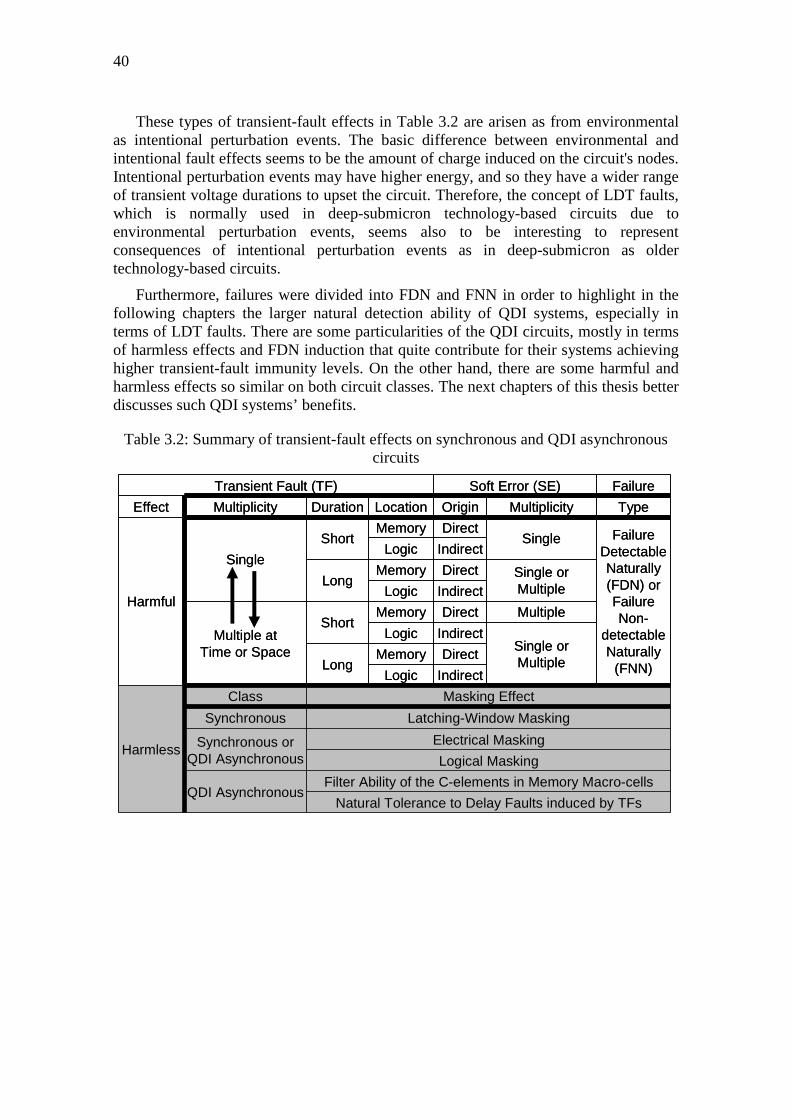
40
These types of transient-fault effects in Table 3.2 are arisen as from environmental as intentional perturbation events. The basic difference between environmental and intentional fault effects seems to be the amount of charge induced on the circuit's nodes. Intentional perturbation events may have higher energy, and so they have a wider range of transient voltage durations to upset the circuit. Therefore, the concept of LDT faults, which is normally used in deep-submicron technology-based circuits due to environmental perturbation events, seems also to be interesting to represent consequences of intentional perturbation events as in deep-submicron as older technology-based circuits.
Furthermore, failures were divided into FDN and FNN in order to highlight in the following chapters the larger natural detection ability of QDI systems, especially in terms of LDT faults. There are some particularities of the QDI circuits, mostly in terms of harmless effects and FDN induction that quite contribute for their systems achieving higher transient-fault immunity levels. On the other hand, there are some harmful and harmless effects so similar on both circuit classes. The next chapters of this thesis better discusses such QDI systems’ benefits.
Table 3.2: Summary of transient-fault effects on synchronous and QDI asynchronous circuits
Transient Fault (TF) Soft Error (SE) Failure
Effect Multiplicity Duration Location Origin Multiplicity Type
Harmful
Single
ShortMemory Direct
Single Failure Detectable Naturally (FDN) or Failure Non-
detectable Naturally
(FNN)
Logic Indirect
LongMemory Direct Single or
MultipleLogic Indirect
Multiple atTime or Space
ShortMemory Direct Multiple
Logic IndirectSingle or MultipleLong
Memory Direct
Logic Indirect
Harmless
Class Masking Effect
Synchronous Latching-Window Masking
Synchronous or QDI Asynchronous
Electrical Masking
Logical Masking
QDI AsynchronousFilter Ability of the C-elements in Memory Macro-cells
Natural Tolerance to Delay Faults induced by TFs

4 EVALUATING TRANSIENT-FAULT EFFECTS AT LOGICAL LEVEL
IC designs necessarily have to be evaluated under the effects of different fault types, given the scenario of errors and failures discussed in previous chapter. In fact, they have to be tested whether their functional behaviours and immunity levels are satisfactory for the purposes specified. Such assessments allow identifying potential vulnerability situations of the circuit that can thus be redesigned or even protected by more efficient mitigation mechanisms. Such testing evaluations to verify the circuit conditions can be done at different abstraction levels of the system’s design. Abramovici (1990), Smith (1997), and Wagner (2004) relate the usual abstraction levels from the lowest to the highest one as shown below:
• Real-circuit level: circuits’ prototypes or circuits produced by physical materials from a fabrication technology;
• Electrical level: circuits’ layout masks, circuits’ models based on transistors, resistors, capacitors, and inductors. Some authors consider layout mask issues as part of the labeled physical level, which may also used to denominate the real-circuit level described above. However, in order to avoid confusions, this thesis stands “physical level” only for the electrical-level-related issues discussed in the first sentence of this paragraph. Moreover, other authors define switch level as transistors modeled discretely (switches at logic level 0 or 1) and transistor level as transistors characterized by non-linear models (e.g., exponential equations);
• Logical level: circuits’ models based on flip-flops, latches, and logic gates, besides library cells. EDA tools usually label a model in terms of logic gates as gate level;
• Micro-architectural level or the well-known Register Transfer (RT) level: the circuit models based on registers, multiplexers, and operators like adders, subtracters, multipliers, and dividers, besides other macrocells. Some authors label this level as behavioral level or even functional level in accordance with the delay model used;
• Algorithmic level: the circuit models based on hardware modules. Modules, cores, plans of power, ground, and clock;
• Systemic level: the circuit models based on processors, memories, and other peripherals, besides circuit boards and their components.
Testing evaluations at real-circuit level by using prototypes or FPGA-based reconfigurable platforms, for instance, does not always allow monitoring and

42
diagnosing certain internal errors. Furthermore, the configuration of a hardware framework dedicated to test a specific type of fault in a target circuit is neither cheap nor a simple task. Therefore, the evaluations usually fall on the electrical level by using software-based tools (e.g., spice, spectre, hspice, etc), which allow simulating the circuit behaviour through equations based on preliminary transistor characterization and modelling. The different types of faults that may occur at real-circuit abstraction level can thus also be characterized and modelled by representations at electrical abstraction level.
However, an electrical-level fault-simulation alternative may consume too much time and computational effort when the target circuits have a certain complexity. The simulation task may even be much more difficult to evaluate the effects of faults with temporal characteristics such as, for instance, the transient faults.
Hence, logical abstraction level simulations based on logic event-driven simulators (e.g., modelsim, nclaunch, etc) are usually suggested in order to enable such a computational task for evaluation of transient-fault effects. Even if they have no the best accuracy to characterize and model the transient faults, they are able to provide meaningful results to identify sensitive instants and zones of a circuit, and thus allowing comparative analysis in terms of robustness in different circuits.
Nowadays, the evaluation of transient-fault effects on synchronous circuits is evident through many simulation-based methods at logical level (MASSENGILL et al, 2000; ALEXANDRESCU; ANGHEL; NICOLAIDIS, 2002, 2004; REORDA; VIOLANTE, 2004; HADJIAT, AMMARI, LEVEUGLE, 2005; NEVES et al, 2006-a; NEVES et al, 2006-b). However, the same methodologies cannot be applied to asynchronous circuits, since they are based on the clock of synchronous systems. Furthermore, the particularities of the transient-fault effects on asynchronous systems’ C-elements are not considered. On the other hand, Monnet (2004, 2005-c 2006-c 2007-a) was the only one to propose a method to evaluate the QDI asynchronous circuits’ sensitivity to such effects. However, his method cannot evaluate synchronous circuits, since it provides a metric which represent the circuit’s sensitivity by only counting the total time when the QDI system’s C-elements are vulnerable to transient faults. The methodology, therefore, allows only comparing the sensitivities of QDI asynchronous architectures. Any comparison of such specific metric for QDI circuits with metrics of methods dedicated to synchronous circuits would not be possible.
Hence, a new methodology able to compare the sensitivities of both (synchronous and asynchronous QDI circuits) is required to evaluate the best design options in terms of transient-fault robustness. For that, the following sections propose a solution presented also in (BASTOS et al, ETS 2009-a; BASTOS et al, IOLTS 2009-b) which provides evaluation metrics common to both these classes of circuits.
4.1 Method for Logical-Level Evaluation of Transient-Fault Effects This new methodology is developed by traditional means of transient-fault-injection
simulation campaigns in gate-level circuits’ designs. The clock period of synchronous systems and the transient-fault vulnerability time of QDI asynchronous systems’ C-elements are abstracted through a probability distribution which requires a sample of small size (i.e., a small number of transient-fault-injection simulation situations). The aim is made an evaluation of SET effects which cause system’s failures.

43
The methodology is able to analyze complex circuits under such faults by using a commercial logic event-driven simulator, a gate-level circuit netlist, and its circuit timing information in a SDF (Standard Delay Format) file. Furthermore, a typical command of commercial simulators (e.g., “force”) models and injects the fault. Figure 4.1 briefly presents the simulation scheme employed by the methodology.
Figure 4.1: Simulation scheme of a SET on an IC-design netlist
4.1.1 Modelling the Transient-Fault Effects
A rectangular-pulse-based model detailed in (ALEXANDRSCU; ANGHEL; NICOLAIDIS, 2004) is utilized to simulate a SET fault at gate level. The command forces a netlist’s node (wire or signal of netlist) to its reverse value just during a time in order to model a transient pulse width (i.e., a transient fault’s duration). Figure 4.2 illustrates such a modelling to inject a transient fault on a netlist’s wire.
Figure 4.2: Modelling of a SET fault on a netlist’s wire
For a complete evaluation of the SET effects, the methodology also considers the possibility of dSE occurrences detailed in chapter 3. As the approach is over a gate-level circuit, a SET happening inside a memory cell cannot be modeled in the same way discussed in previous paragraph. Hence, the method considers each memory cell as an extra netlist’s node. In fact, every simulation evaluating output wires of memory cells is executed again but under a different fault-injection model. The same command “force” is used with a different parameter to represent a dSE. This command is thus able to deposit in an output wire of memory cell its reverse value. However, unlike a stuck-at fault, such a deposit can be eliminated by a subsequent driver transaction.
On the other hand, as explained in chapter 3, the method must take into consideration the C-element’s dual behaviour (memory-buffer) depending on its input
Pulse Width
Simulation of a Transient-Fault Injection on a :Netlist Wire
Pulse Width
Fault Initial Time Total Computation TimeInitial Computation Time
Logic Event -Driven Simulator
Gate-Level Netlist (verilog)
Timing Information
File (sdf)
Stimulus Vector (vhdl)
Resultant Simulation File
Golden Resultant
Simulation File X
Count Files with Failure at Circuit Outputs
Netlist Wire
Pulse Width
Fault Initial Time
Configuration File (tcl)

44
values. If inputs are different, the C-element’s output is forced as a deposit (dSE), else if inputs are equal, it is forced as a pulse (SET).
Therefore, for a set of a stimulus vector, a fault initial time, and a pulse width, each simulation illustrated in Figure 4.3, Figure 4.4, and Figure 4.5 is separately executed depending on the circuit’s class or logic values of C-element’s inputs. Other memory types are also approached by considering their particularities.
Figure 4.3: Fault-injection simulations into a synchronous circuit
Figure 4.4: Fault-injection simulations into a QDI asynchronous circuit with different logic values at its C-element’s inputs
Figure 4.5: Fault-injection simulations into a QDI asynchronous circuit with equal logic values at its C-element’s inputs
4.1.2 Dynamic of Fault-Injection Simulations
The goal is to compare in a fair way the robustness of circuits functionally equivalent but architecturally different. Therefore, the target circuits for comparison are
Sim
ulat
ion
3
SE
T
C
Computational Logic Block
Memory Block
Sim
ulat
ion
1
SE
T
Sim
ulat
ion
2
SE
T
Sim
ulat
ion
4
SE
T
Sim
ulat
ion
5
SE
T
Sim
ulat
ion
6
SE
T
0
0
Sim
ulat
ion
3
SE
T
C
Computational Logic Block
Memory Block
Sim
ulat
ion
1
SE
T
Sim
ulat
ion
2
SE
T
Sim
ulat
ion
4
SE
T
Sim
ulat
ion
5
SE
T
Sim
ulat
ion
6
dSE
1
0
Sim
ulat
ion
3
SE
T
D-FF
Combin ational Logic Block
Memory Block
Sim
ulat
ion
1
SE
T
Sim
ulat
ion
2
SE
T Simulation
4 SET
Sim
ulat
ion
5
SE
T
Sim
ulat
ion
6
dSE
CLK

45
evaluated under similar simulation conditions. The scheme in Figure 4.1 is used several times in accordance with Figure 4.6.
A same set of input vectors is randomly chosen to simulate functional operations of the circuits. The initial instant to start the transient pulse is defined as a percentage of the total computation time, which means the number of execution cycles multiplied by the inverse of the circuit’s operating frequency, as defined in chapter 3. Then, in a first simulation, a fault starts to be injected at 5 % of the total computation time. In another simulation, the fault starts at 10 %. After that, the simulations go on in accordance with Figure 4.6. Note that each one of all netlist wires is individually evaluated by an independent fault-injection simulation.
Figure 4.6: Simulation methodology for injection of SETs
Furthermore, a typical range of pulse widths (DODD, 2004; FERLET-CAVROIS, 2006) is evaluated. Only a width by simulation set is chosen in order to estimate and compare the target circuits’ robustness for a certain transient-fault characteristic. Therefore, for each width chosen within the range, all nodes (netlist’s wires) of the target circuits are evaluated under rectangular pulses that have obviously the same width and the same magnitude Vdd, since it is a logical-level simulation.
Observe, however, that the characteristics of a SET depend largely on the perturbed node’s capacitance and the charge deposited by the perturbation. As the nodes’ capacitances in the target circuits for comparison are often different, a same perturbation charge occurring on different circuits would present also different transient effects. Therefore, the SETs generated in each one of the target circuits would likely have different characteristics in terms of amplitude, width, rise and fall times. Hence, when all of the target circuits’ nodes are perturbed by a rectangular SET with the same width and amplitude, the capacitances of all these nodes have to be considered similar if the goal is analyzing comparatively the effects of a certain perturbation charge. On the other hand, a comparative evaluation by using a set of widths, within the typical SET range, allows considering approximately the different nodes’ capacitances in the target circuits. Actually, at least the characteristics of different widths generated by a certain
for each Stimulus Vector
next Stimulus Vector
for each Netlist Wire { all netlist wires }
next Netlist Wire
for each Fault Initial Time { 5% 10% … 90% 95% of total computation time }
next Fault Initial Time
for each Pulse Width { 250ps 500ps 750ps … }
next Pulse Width
SSiimmuullaattiioonn SScchheemmee ooff aa SSEETT

46
perturbation charge would be taken into account. Then, if such an approach based on multiple widths is used, the nodes’ capacitances have not necessarily to be considered similar. Consequently, a more accurate evaluation can be done, even though there are certain inaccuracies mostly related to the SET’s amplitude as well the SET’s rise and fall times.
Such simplifications, which are indeed typical in any method at logical abstraction level, greatly reduce the simulation complexity in terms of computational efforts. On the other hand, they also allow evaluating the behavior of a system under a certain transient-fault profile (i.e., a pulse width) in all circuit’s nodes, regardless of its capacitance and perturbation charge. Therefore, logical-level methods ensure thus a very significant preliminary low-cost evaluation, even so new practical works based on real-circuit-level experiments have yet to further explore how inaccurate exactly they are.
The simulations of SETs causing dSEs follow the same methodology shown in Figure 4.6. The difference is that only the netlist’s wires of memory cells’ outputs are targets for injections. Therefore, pulse widths are not considered but a logic value to deposit, as explained in previous section.
4.1.3 Evaluation Metrics
A set of configuration files, as described in Figure 4.1, defines different transient-fault characteristics to be individually simulated. In fact, just a single transient fault is injected by simulation in accordance with the SET-based model. Consequently, the total number of injected transient faults is equal to the total number of simulations under fault:
TotNumSim TotNumFaul= (4.1)
The method provides a file after a simulation under the effect of an injected SET. Then, such a resultant file is compared with another in fault-free simulation conditions (golden file). If files are different, the target circuit’s primary outputs presented inconsistent values. Therefore, the injected SET caused a system’s failure. By counting every simulation that presented such a scenario, system-robustness percentages based on the TotNumSim can be calculated. Note that just a failure by simulation is able to happen.
The total number of eventual system’s failures is divided, as defined in chapter 3, into failures detectable and non-detectable naturally (FDN and FNN) by the system:
DetecNumFailNonecNumFailDetTotNumFail += (4.2)
So, the percentage of system’s Detection is defined as:
100⋅=TotNumSim
ecNumFailDetDetection (4.3)
On the other hand, certain transient faults often cause no system’s failures. It means the system naturally tolerates the injected faults by those masking effects explained in chapter 3. The total number of faults tolerated naturally (FTN) is thus represented by:
TotNumFailTotNumSimNumFaulTol −= (4.4)

47
As each one of the TotNumFail is provoked by a different single fault, the TotNumFaul is divided as shown in Figure 4.7. Then, the percentage of system’s Tolerance is expressed as:
100⋅=TotNumSim
NumFaulTolTolerance (4.5)
Figure 4.7: The total number of injected transient faults and their consequences
Another important system-robustness percentage is the resistance to faults. It denotes how robust the system is to cope with the transient-fault effects. Such a percentage of system’s Resistance is defined as the sum of the system’s Detection and Tolerance detailed in equations 4.3 and 4.5:
100⋅
+=TotNumSim
NumFaulTolecNumFailDetResistance (4.6)
4.1.3.1 Circuit’s Sensitivity to SET Effects
The methodology considers two basic concepts in order to compare the sensitivities of different circuits:
• Any target always will have a higher probability to be hit by single perturbation event, for instance, if its area is larger;
• The probability is also higher if the target is exposed longer time to attempts at hitting it (i.e., to single perturbation events at hitting a circuit).
Therefore, the circuits’ area sizes and the total computation times are taken into account to determine what circuit is the most sensitive to SET effects. For that, another evaluation metric which uses units common to any circuit is defined. Only by means of that, a comparison between sensitivities of different circuits, in terms of area or total computation time, is feasible.
The methodology works with the area factor by using the logic idea that the total number of nodes (TotNumNod) increases in function of enlarging the circuit’s area. The circuit’s nodes (netlist’s wires) are targets of fault-injection simulations. In addition, the system-robustness metrics, defined in previous section, take them into consideration. At that abstraction level of the system’s design, which is used in such a methodology, the evaluation is simplified by comparing simulations of different circuits under pulses, with the same width, on each node. Hence, all nodes have the same capacitive importance and the numbers of sensitive nodes identified in different circuits are
TotNumFaul =
TotNumSim
NumFaulTol
NumFailDetec
NumFailNonDetec
TotNumFail
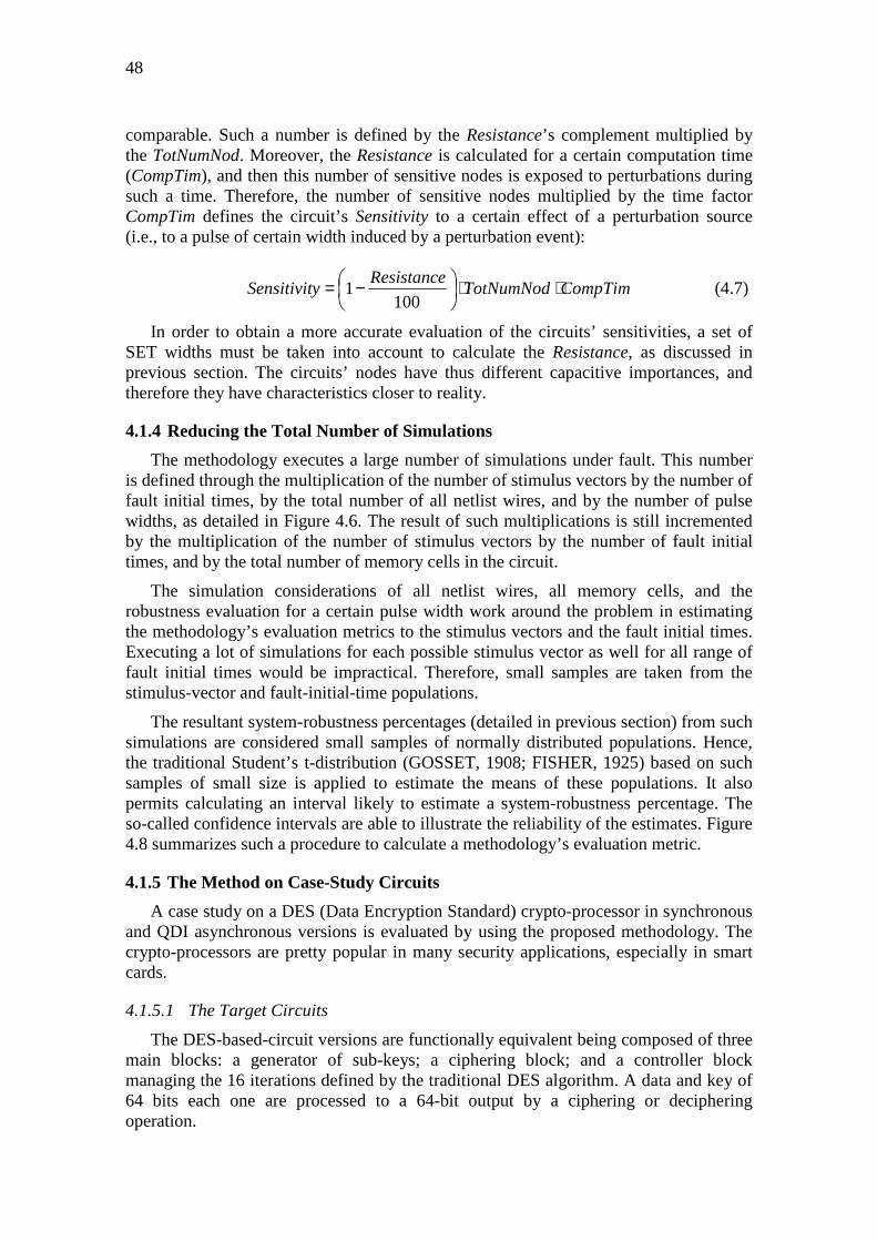
48
comparable. Such a number is defined by the Resistance’s complement multiplied by the TotNumNod. Moreover, the Resistance is calculated for a certain computation time (CompTim), and then this number of sensitive nodes is exposed to perturbations during such a time. Therefore, the number of sensitive nodes multiplied by the time factor CompTim defines the circuit’s Sensitivity to a certain effect of a perturbation source (i.e., to a pulse of certain width induced by a perturbation event):
CompTimTotNumNodResistance
ySensitivit ⋅⋅
−=100
1 (4.7)
In order to obtain a more accurate evaluation of the circuits’ sensitivities, a set of SET widths must be taken into account to calculate the Resistance, as discussed in previous section. The circuits’ nodes have thus different capacitive importances, and therefore they have characteristics closer to reality.
4.1.4 Reducing the Total Number of Simulations
The methodology executes a large number of simulations under fault. This number is defined through the multiplication of the number of stimulus vectors by the number of fault initial times, by the total number of all netlist wires, and by the number of pulse widths, as detailed in Figure 4.6. The result of such multiplications is still incremented by the multiplication of the number of stimulus vectors by the number of fault initial times, and by the total number of memory cells in the circuit.
The simulation considerations of all netlist wires, all memory cells, and the robustness evaluation for a certain pulse width work around the problem in estimating the methodology’s evaluation metrics to the stimulus vectors and the fault initial times. Executing a lot of simulations for each possible stimulus vector as well for all range of fault initial times would be impractical. Therefore, small samples are taken from the stimulus-vector and fault-initial-time populations.
The resultant system-robustness percentages (detailed in previous section) from such simulations are considered small samples of normally distributed populations. Hence, the traditional Student’s t-distribution (GOSSET, 1908; FISHER, 1925) based on such samples of small size is applied to estimate the means of these populations. It also permits calculating an interval likely to estimate a system-robustness percentage. The so-called confidence intervals are able to illustrate the reliability of the estimates. Figure 4.8 summarizes such a procedure to calculate a methodology’s evaluation metric.
4.1.5 The Method on Case-Study Circuits
A case study on a DES (Data Encryption Standard) crypto-processor in synchronous and QDI asynchronous versions is evaluated by using the proposed methodology. The crypto-processors are pretty popular in many security applications, especially in smart cards.
4.1.5.1 The Target Circuits
The DES-based-circuit versions are functionally equivalent being composed of three main blocks: a generator of sub-keys; a ciphering block; and a controller block managing the 16 iterations defined by the traditional DES algorithm. A data and key of 64 bits each one are processed to a 64-bit output by a ciphering or deciphering operation.
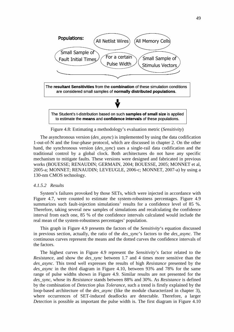
49
Figure 4.8: Estimating a methodology’s evaluation metric (Sensitivity)
The asynchronous version (des_async) is implemented by using the data codification 1-out-of-N and the four-phase protocol, which are discussed in chapter 2. On the other hand, the synchronous version (des_sync) uses a single-rail data codification and the traditional control by a global clock. Both architectures do not have any specific mechanism to mitigate faults. These versions were designed and fabricated in previous works (BOUESSE; RENAUDIN; GERMAIN, 2004; BOUESSE, 2005; MONNET et al, 2005-a; MONNET; RENAUDIN; LEVEUGLE, 2006-c; MONNET, 2007-a) by using a 130-nm CMOS technology.
4.1.5.2 Results
System’s failures provoked by those SETs, which were injected in accordance with Figure 4.7, were counted to estimate the system-robustness percentages. Figure 4.9 summarizes such fault-injection simulations’ results for a confidence level of 85 %. Therefore, taking several new samples of simulations and recalculating the confidence interval from each one, 85 % of the confidence intervals calculated would include the real mean of the system-robustness percentages’ population.
This graph in Figure 4.9 presents the factors of the Sensitivity‘s equation discussed in previous section, actually, the ratio of the des_sync’s factors to the des_async. The continuous curves represent the means and the dotted curves the confidence intervals of the factors.
The highest curves in Figure 4.9 represent the Sensitivity’s factor related to the Resistance, and show the des_sync between 1.7 and 4 times more sensitive than the des_async. This trend well expresses the results of high Resistance presented by the des_async in the third diagram in Figure 4.10, between 93% and 78% for the same range of pulse widths shown in Figure 4.9. Similar results are not presented for the des_sync, whose its Resistance stands between 88% and 30%. As Resistance is defined by the combination of Detection plus Tolerance, such a trend is firstly explained by the loop-based architecture of the des_async (like the module characterized in chapter 3), where occurrences of SET-induced deadlocks are detectable. Therefore, a larger Detection is possible as important the pulse width is. The first diagram in Figure 4.10
Populations:All Memory CellsAll Netlist Wires
Small Sample of
Fault Initial Times Small Sample of
Stimulus Vectors
For a certain
Pulse Width
Populations:All Memory CellsAll Netlist Wires
Small Sample of
Fault Initial Times Small Sample of
Stimulus Vectors
For a certain
Pulse Width
The resultant Sensitivities from the combination of these simulation conditionsare considered small samples of normally distributed populations .
The Student’s t-distribution based on such samples of small size is appliedto estimate the means and confidence intervals of these populations.
Populations:All Memory CellsAll Netlist Wires
Small Sample of
Fault Initial Times Small Sample of
Stimulus Vectors
For a certain
Pulse Width
Populations:All Memory CellsAll Netlist Wires
Small Sample of
Fault Initial Times Small Sample of
Stimulus Vectors
For a certain
Pulse Width
The resultant Sensitivities from the combination of these simulation conditionsare considered small samples of normally distributed populations .
The Student’s t-distribution based on such samples of small size is appliedto estimate the means and confidence intervals of these populations.

50
shows it. Furthermore, the Tolerance of the des_async is not quite reduced for larger pulses as a result of the two particular masking effects (d) and (e), discussed in chapter 3, and the absence of the latching-window masking, which decreases in the des_sync. It is detailed in the second diagram in Figure 4.10.
Figure 4.9: Circuits’ Sensitivities in terms of the ratio des_sync / des_async
The circuits’ area sizes and the computation times in the Sensitivity’s equation are illustrated by the lowest curves in Figure 4.9. The larger size of the des_async (around 5 times the TotNumNod on the des_sync) leaves it approximately 5 times more sensitive than the des_sync. Moreover, its larger computation time (around 4 times the CompTim of the des_sync) leaves the des_async about 4 times yet more sensitive. As the lowest curves show, the multiplication of all the Sensitivity’s factors determines the des_async between 5 and 12 times more sensitive than the des_sync. It illustrates the importance of the area and time factors that overcome the factor related to the Resistance in this case-study. On the other hand, the des_async could be developed by using the advances in synthesis tools and libraries of cells dedicated to asynchronous (MAURINE et al, 2003; FOLCO et al, 2005; TIEMPO, 2009). It would optimize the area factor to 2 instead of 5 and could provide lower computation time than the des_sync. Therefore, the factor related to the Resistance would be predominant and the des_async could be less sensitive.
0.000.100.200.300.400.500.600.700.800.901.001.101.201.301.401.501.601.701.801.902.002.102.202.302.402.502.602.702.802.903.003.103.203.303.403.503.603.703.803.904.004.10
50 250 450 650 850 1050 1250 1450 1650 1850 2050 2250Pulse Width (ps)
(1-Resistance*100)*TotNumNod*CompTim
(1-Resistance/100)*TotNumNod
(1-Resistance/100)
des_
sync
Y ti
mes
mor
e S
ET
sen
sitiv
e
des_
asyn
c Y
tim
es le
ss S
ET
sen
sitiv
e
Y

51
Figure 4.10: System-robustness percentages
Figure 4.11 was obtained by extrapolating from Figure 4.9’s trends. However, it also considers typical trends of the novel synthesis methods for asynchronous (MAURINE et al, 2003; FOLCO et al, 2005; TIEMPO, 2009), for instance, an area factor of 2 instead of 5 and a computation time factor of 1 instead of 4. Figure 4.11 shows thus that the des_sync can be up to twice more sensitive than the des_async by using such modern
System's Detection (%)
18.77
1.11
16.65
0.58
16.12
0.46
14.36
0.39
23.01
1.21
20.41
0.71
19.82
0.55
17.09
0.43
14.53
1.01
12.89
0.45
12.43
0.38
11.63
0.350
5
10
15
20
25
250ps 250ps 500ps 500ps 750ps 750ps2128ps2128ps
des_sync des_async
250 ps 500 ps 750 ps 2128 ps
Sytem's Tolerance (%)
64.4
0
39.7
2
69.5
6
65.0
1
70.5
3
72.8
8
75.9
5
81.6
4
66.70
49.76
71.7976.2772.8782.1778.24
87.63
62.09
29.67
67.3453.75
68.2063.5973.6675.65
0102030405060708090
100
250ps 250ps 500ps 500ps 750ps 750ps2128ps2128ps250 ps 500 ps 750 ps 2128 ps
des_sync des_async
Sytem's Resistance (%)
83.2
4
40.8
3
86.2
5
65.5
9
86.8
3
73.3
590.5
3
82.0
3
87.83
50.82
90.00
76.75
90.24
82.59
93.0188.00
78.66
30.85
82.50
54.44
83.41
64.11
88.05
76.06
0102030405060708090
100
250ps 250ps 500ps 500ps 750ps 750ps2128ps2128ps
des_sync des_async
250 ps 500 ps 750 ps 2128 ps
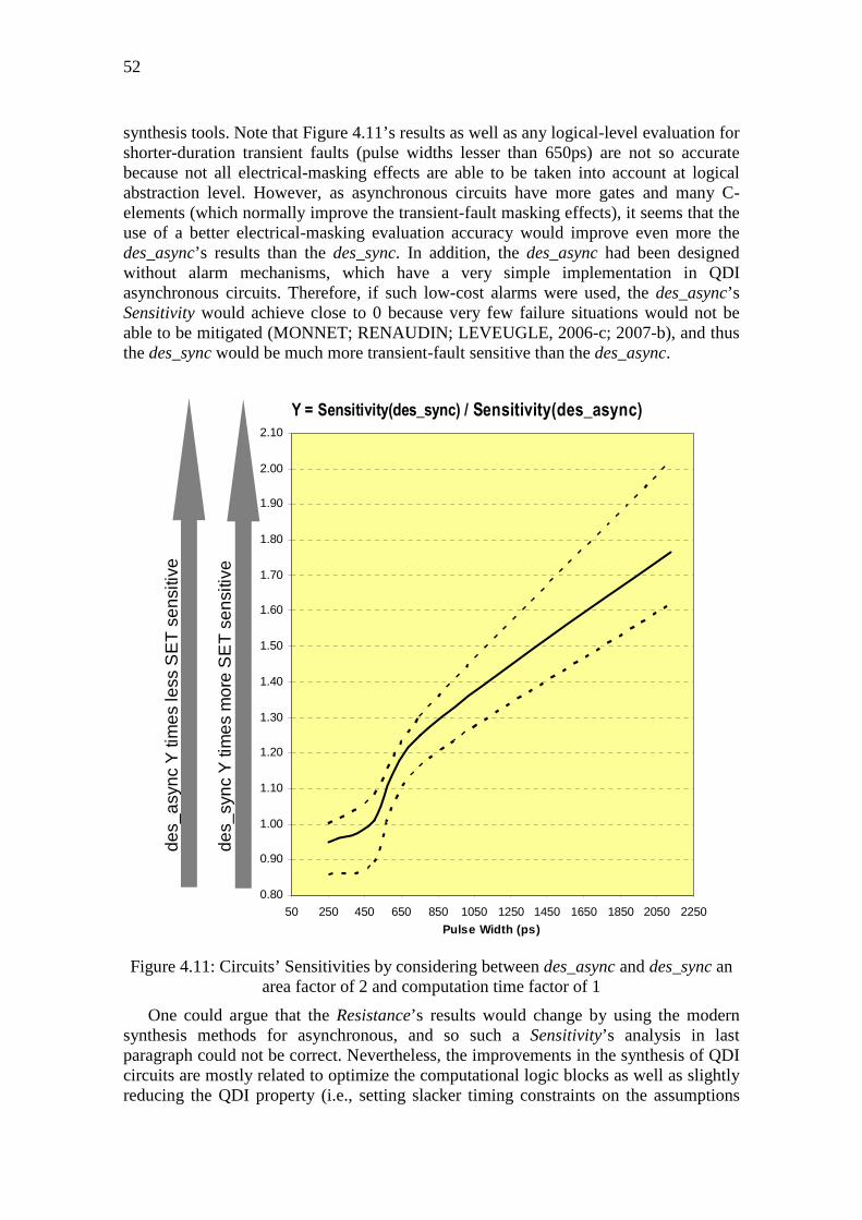
52
synthesis tools. Note that Figure 4.11’s results as well as any logical-level evaluation for shorter-duration transient faults (pulse widths lesser than 650ps) are not so accurate because not all electrical-masking effects are able to be taken into account at logical abstraction level. However, as asynchronous circuits have more gates and many C-elements (which normally improve the transient-fault masking effects), it seems that the use of a better electrical-masking evaluation accuracy would improve even more the des_async’s results than the des_sync. In addition, the des_async had been designed without alarm mechanisms, which have a very simple implementation in QDI asynchronous circuits. Therefore, if such low-cost alarms were used, the des_async’s Sensitivity would achieve close to 0 because very few failure situations would not be able to be mitigated (MONNET; RENAUDIN; LEVEUGLE, 2006-c; 2007-b), and thus the des_sync would be much more transient-fault sensitive than the des_async.
Figure 4.11: Circuits’ Sensitivities by considering between des_async and des_sync an area factor of 2 and computation time factor of 1
One could argue that the Resistance’s results would change by using the modern synthesis methods for asynchronous, and so such a Sensitivity’s analysis in last paragraph could not be correct. Nevertheless, the improvements in the synthesis of QDI circuits are mostly related to optimize the computational logic blocks as well as slightly reducing the QDI property (i.e., setting slacker timing constraints on the assumptions
0.80
0.90
1.00
1.10
1.20
1.30
1.40
1.50
1.60
1.70
1.80
1.90
2.00
2.10
50 250 450 650 850 1050 1250 1450 1650 1850 2050 2250
Pulse Width (ps)
Y = Sensitivity(des_sync) / Sensitivity(des_async)
des_
sync
Y ti
mes
mor
e S
ET
sen
sitiv
e
des_
asyn
c Y
tim
es le
ss S
ET
sen
sitiv
e

53
that require, in theory, similar delays in branches of isochronic forks). Therefore, the Resistance’s results could be slightly different depending on an eventual reduction of the des_async’s Tolerance, which would be perhaps modified due to its direct relation with the logical-masking effects. Evidently, the des_async’s logical-masking effects may be improved with the new logic synthesis methods and thus more FTN (faults tolerated naturally) cases would happen. Actually, it is something yet to be further investigated in future works. However, such methods clearly maintain the QDI asynchronous circuits’ features (i.e., the data codification and the asynchronous handshaking communication) that make possible the generation of deadlocks, and so failures detectable naturally (FDN), as further discussed in chapter 5. Therefore, even using these new synthesis methods, the very stronger QDI circuits’ natural ability to often produce FDN instead of FNN is preserved as well as the higher des_async’s Detection. In fact, the des_async’s Detection would be certainly improved because FTN cases would become either FNN, which are detectable in most of the SE (soft errors) situations (MONNET; RENAUDIN; LEVEUGLE, 2006-c; 2007-b) by implementing alarms, or FDN (what is more probable, as discussed in chapter 5). Thus, even if there could be a logical-masking diminution, FTN cases have greater chances of becoming FDN. Similarly, a QDI property’s reduction would make the system more vulnerable to failures but also very likely FDN, mostly in LDT (long-duration transient faults) situations. Then, the Resistance’s results for QDI systems designed by modern asynchronous-dedicated methods would be few modified, since in the worst case the system’s Tolerance would be probably slightly reduced but the system’s Detection would be certainly further improved. Furthermore, the implementation of alarms for FNN situations always would ensure a very-strong and higher QDI system’s Resistance in comparison with its synchronous counterpart.
4.2 Conclusions A new SET-effect evaluation methodology common to both synchronous and
asynchronous circuits is shown in this chapter. It is based on the traditional fault-injection simulations. However, a probability distribution and confidence intervals are used to decrease the total number of simulations. Furthermore, the particularities of asynchronous circuits are considered by analyzing the inputs of all C-elements in the circuit. Metrics are provided to identify for a certain functional block (e.g., a multiplier, an adder) the class or type of circuit design that is more transient-fault sensitive. It means the methodology is interesting to compare different circuit implementations of a functional block.
At the case study, the results show the des_sync less sensitive to SET effects just due to its smaller area and lower computation time. However, the highest curves in Figure 4.9 as well as the extrapolation’s results in Figure 4.11 illustrate the high potential of the des_async to have lower Sensitivity when using design methods more optimized in terms of area and computation time. Aggregating it with the great ability to detect and correct errors, and the features of lower EMI and higher security properties, the asynchronous circuit becomes quite attractive to design a more robust system.

54

5 ASYNCHRONOUS CIRCUITS AS ALTERNATIVE FOR MITIGATION OF LONG-DURATION TRANSIENT FAULTS IN DEEP-SUBMICRON TECHNOLOGIES
Transient faults in deep-submicron technology-based ICs expose them to more severe effects than in older technologies. Indeed, faster nanoelectronic circuits, for instance, have shorter delays, and then transient faults’ durations have become comparable or even longer than critical circuit paths’ delays. Electronics systems are thus more vulnerable to failure situations.
Such a worse scenario in deeper-submicron technologies has been predicted by many researches in last years. Tosaka et al. (1998) highlighted already considerable soft error rates (SERs) in 350-nm CMOS ICs at ground level. Hazucha et al. (2003) identified at sea level conditions that the SER per bit of SRAMs in 250 nm, 180 nm, 130 nm, and 90 nm technologies increases by 8% per generation. Such a SER’s increase in deep-submicron technologies at ground level was also reported by Granlund (2003), Borkar (2005), and many other works. In space or even at flight altitudes, this IC vulnerability trend is obviously yet worse (NORMAND; BAKER, 1993; LABEL et al, 1996; BARTH, 1997; LABEL et al, 2000; NORMAND, 2001).
Past researches also showed that combinational logic in synchronous circuits is much less sensitive to provoke SEs than memory elements (LIDÉN et al, 1994; GAISLER, 1997). In fact, memories always were considered the most vulnerable to SEs due to their spatial density and the amount of information that they can store (MAHESHWARI; KOREN; BURLESON, 2003). Moreover, transient faults arisen closer to memory elements, in theory, have higher probability to cause SEs. Therefore, if a transient fault was generated in a memory element, the chance that it causes a SE would be higher than a transient fault in a combinational logic, which would be farther from a memory element. Nevertheless, deep-submicron technologies in last years allow high IC’s complexities and higher clock’s frequencies, and so the SER arisen in combinational logic circuits becomes as relevant as the SER in memory elements, as Shivakumar (2002) predicted for synchronous systems.
Another lower-probability problem, investigated in more details since the deeper-submicron technologies, is the occurrence of multiple-transient faults which may cause multiple-bit upset (MBU). In fact, even a single transient fault (i.e., a SET) may, mostly in more complex circuits, generate MBU. Moreover, transistors, in recent denser circuits, are closer to each other, and then it may lead a single radiation-induced particle (as an environmental perturbation event) upsetting different circuit’s nodes, and so generates multiple-transient faults (MAIZ et al, 2003; NEUBERGER et al, 2003; ROSSI et al, 2005).

56
Furthermore, other researches highlight that transient-fault durations really have become in deeper-submicron technologies as important as the clock’s periods of synchronous systems (DODD, 2004; FERLET-CAVROIS, 2006; LISBOA, 2007-a). Lisboa (2009) characterizes such worse effects of transient faults in deeper-submicron technologies as long-duration transient (LDT) faults. He proves (Figure 5.1) that widths of transient faults, arisen from radiation-induced particles with modest linear energy transfer (LET = 10 MeV-cm2/mg, for instance), can be longer than delays (cycle times) of circuit paths (inverter chains) in 130-nm and 100-nm CMOS technologies. Lisboa (2009) also shows that the costs to mitigate such LDT faults by using traditional spatial or temporal redundancy-based techniques become very expensive in terms of system’s overheads, especially because more redundancy is required to cope with these longer effects.
Figure 5.1: Transient-fault width vs. clock’s cycle time scaling (LISBOA, 2009)
Deep-submicron technologies, therefore, bring along with their many benefits also such vulnerabilities, and thus greater challenges to protect ICs. Nevertheless, this chapter as well as the work in (BASTOS et al, ETS 2010-a; BASTOS et al, ESREF & Microelectronics Reliability Journal 2010-c) shows innovatively that such a worse scenario does not happen in QDI asynchronous systems, mostly due to their efficient natural ability to mitigate LDT faults. Such an additional benefit pushes on the asynchronous design as a better alternative for mitigation of transient faults in deep-submicron technologies.
5.1 Natural Detection of Failures As discussed in chapter 3, transient faults in ICs may be tolerated naturally (FTN:
faults tolerated naturally) by masking effects or they may provoke SEs. SEs almost always imply a failure at circuit’s primary outputs (CPOs). However, as most of the ICs control the amount of iteration cycles and indicate an output signal of end operation (SEO, like in Figure 3.1), an eventual lack of indication due to a failure is easily detectable by the system. Such a failure scenario is thus detectable naturally (FDN:

57
failure detectable naturally) without requiring any additional hardware and easily corrected by recomputation. On the other hand, if the SEO is well indicated and a failure arises at the other CPOs, extra hardware mechanisms for detection are necessary to mitigate such a failure non-detectable naturally (FNN) without using costly software-based techniques. Table 5.1, which is further discussed in chapter 3, summarizes these effects of transient faults in accordance with the CPOs.
Table 5.1: Possible CPOs of a system perturbed by transient faults
Values at CPOs Consequence
SEO Other CPOs OK OK FTN
Inconsistent OK FDN Inconsistent Inconsistent FDN
OK Inconsistent FNN
5.1.1 Ability of QDI Asynchronous Systems
Unlike synchronous circuits, the QDI asynchronous circuits have a natural ability to transform most of the SE cases into FDN in any IC fabrication technology. It means that the largest part of the failure situations are detectable by the QDI system without any extra hardware. Such a natural property of a QDI circuit is justified by its architecture.
A QDI architecture controls the sequence of its data flow at the end of each one of its iteration cycles. Each cycle needs to have all phases of the handshaking protocol, as illustrated in Figure 2.3, for instance. Any event which perturbs the protocol’s phases can lead the system to lose its correct data sequence. Such a loss of synchronization between phases of a cycle induces a deadlock over the system’s data flow in most of the SE cases (MONNET; RENAUDIN; LEVEUGLE, 2006-c; 2007-b). Indeed, an iteration cycle does not succeed in finishing its goal, and thus a data element is lost or an additional one is inserted.
Normally, in four-phase protocol, a deadlock situation happens when a SE occurs in a memory element of a system’s stage N by switching from/to a valid or forbidden data to/from an invalid data. Such a scenario indeed generates a wrong acknowledgment (i.e., an acknowledgment in opposite logic state) to the previous system’s stage N-1. Then, for instance, a valid data in a memory element of a system’s stage N can be lost (i.e., become an invalid data) before the next system’s stage N+1 has processed and acknowledged it. As worst consequence, the correct communication between stages is broken, and a deadlock is characterized.
In a first impression, such a deadlock scenario may seem a behavior that disqualifies the QDI systems. However, the majority of QDI architectures count their data elements or even the amount of iteration cycles in order to report a SEO. Therefore, an eventual deadlock always perturbs such a count, and so there is no SEO indication, and a FDN always happens. On the other hand, almost all of the FNN cases are easily detectable by implementing low-cost alarm mechanisms (MOORE et al, 2003; MONNET; RENAUDIN; LEVEUGLE, 2006-c; 2007-b), which identify forbidden data states in the protocol.
In fact, the multi-rail data paths of QDI circuits allow classifying the SEs due to single transient faults into three cases (MONNET; RENAUDIN; LEVEUGLE, 2006-c; 2007-b):
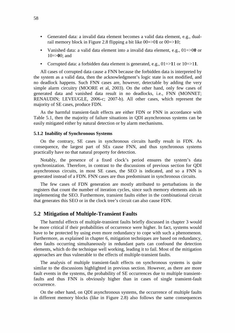
58
• Generated data: a invalid data element becomes a valid data element, e.g., dual-rail memory block in Figure 2.8 flipping a bit like 00=>01 or 00=>10;
• Vanished data: a valid data element into a invalid data element, e.g., 01=>00 or 10=>00; and
• Corrupted data: a forbidden data element is generated, e.g., 01=>11 or 10=>11.
All cases of corrupted data cause a FNN because the forbidden data is interpreted by the system as a valid data, then the acknowledgment’s logic state is not modified, and no deadlock happens. Such FNN cases are, however, detectable by adding the very simple alarm circuitry (MOORE et al, 2003). On the other hand, only few cases of generated data and vanished data result in no deadlocks, i.e., FNN (MONNET; RENAUDIN; LEVEUGLE, 2006-c; 2007-b). All other cases, which represent the majority of SE cases, produce FDN.
As the harmful transient-fault effects are either FDN or FNN in accordance with Table 5.1, then the majority of failure situations in QDI asynchronous systems can be easily mitigated either by natural detection or by alarm mechanisms.
5.1.2 Inability of Synchronous Systems
On the contrary, SE cases in synchronous circuits hardly result in FDN. As consequence, the largest part of SEs cause FNN, and thus synchronous systems practically have no that natural property for detection.
Notably, the presence of a fixed clock’s period ensures the system’s data synchronization. Therefore, in contrast to the discussions of previous section for QDI asynchronous circuits, in most SE cases, the SEO is indicated, and so a FNN is generated instead of a FDN. FNN cases are thus predominant in synchronous circuits.
The few cases of FDN generation are mostly attributed to perturbations in the registers that count the number of iteration cycles, since such memory elements aids in implementing the SEO. Furthermore, transient faults either in the combinational circuit that generates this SEO or in the clock tree’s circuit can also cause FDN.
5.2 Mitigation of Multiple-Transient Faults The harmful effects of multiple-transient faults briefly discussed in chapter 3 would
be more critical if their probabilities of occurrence were higher. In fact, systems would have to be protected by using even more redundancy to cope with such a phenomenon. Furthermore, as explained in chapter 6, mitigation techniques are based on redundancy, then faults occurring simultaneously in redundant parts can confound the detection elements, which do the technique well working, leading it to fail. Most of the mitigation approaches are thus vulnerable to the effects of multiple-transient faults.
The analysis of multiple transient-fault effects on synchronous systems is quite similar to the discussions highlighted in previous section. However, as there are more fault events in the systems, the probability of SE occurrences due to multiple transient-faults and thus FNN is obviously higher than in cases of single transient-fault occurrence.
On the other hand, on QDI asynchronous systems, the occurrence of multiple faults in different memory blocks (like in Figure 2.8) also follows the same consequences

59
discussed in previous section, so there is a huge chance that they result in FDN. The same scenario happens if multiple-transient faults occur at different instants.
Nevertheless, multiple-transient faults occurring in the same QDI system’s memory block can also result in multiple SE, and thus for dual-rail codification, for example, they cause FNN in most cases. Indeed, the SE situations are: 00=>11, which is a case of corrupted data that likely generates a deadlock (i.e., FDN) because the acknowledgment’s logic state is modified; and 01=>10, or 10=>01, which normally produce no deadlocks (therefore FNN) because they keep on the acknowledgment’s logic state. Monnet (2006-c) thus classifies a further SE case in addition to those presented in previous section for single transient faults in QDI systems:
• Modified data: a valid data element is turned into another valid data element, e.g., 01=>10 or 10=>01.
Unfortunately, cases of modified data have no a natural solution to be mitigated, and then they require special extra mitigation mechanisms. However, as well discussed in previous section, the cases of corrupted data that do not become a FDN are easily detectable by a low-cost alarm mechanism (MOORE et al, 2003).
In addition, by using codification M-out-of-N, which is quite normal in QDI circuit’s designs, the chances of corrupted-data cases are much higher, since there will be greater codification redundancy. Therefore, the probability that forbidden data occurs is higher, and so more SE cases are detectable by the alarm mechanism or even by generating naturally deadlocks (FDN). A solution thus to reduce cases of modified data is using a higher codification M-out-of-N than dual rail (i.e., 1-out-of-2).
Even though QDI asynchronous systems under multiple-transient faults do not have the same performance to generate FDN than in single transient-fault situations, they have, nevertheless, better natural mechanisms for mitigation of such multiple faults than synchronous circuits.
5.3 Mitigation of Long-Duration Transient Faults The harmful effects of LDT faults, typical in deep-submicron technologies, are
almost always disastrous for synchronous circuits. For instance, a transient that starts in the second half of a clock cycle and finishes only in the following cycle. A SE scenario is very probable as well a FNN. Moreover, large system’s overheads are necessary to mitigate such a LDT fault (LISBOA, 2007-a).
Nevertheless, such faults in QDI circuits generate FDN in the largest part of SE cases. Indeed, the probability of a deadlock is higher for longer faults, since the transient remains for a longer time on the circuit’s path, and then the few delay-sensitive circuit’s paths are easily reached. The chance of data elements being lost or inserted is bigger.
In addition, even cases of corrupted data due to single faults, which always generate FNN in submicron technologies, can produce deadlocks (i.e., FDN) in deeper-submicron technologies. Such cases, however, happen when the LDT faults occur in QDI system’s elements that are delay sensitive. There is thus a large chance of a SE due to a corrupted data being followed in the next protocol’s phase by another SE that produces a deadlock. Therefore, a longer fault can generate multiple SEs in sequence. As the SE scenarios remain longer time and a larger part of them cause deadlocks (as

60
explained in previous sections), longer duration transient faults have a higher probability to produce a FDN.
5.4 A Case-Study Analysis A case study on a DES (Data Encryption Standard) crypto-processor in synchronous
and QDI asynchronous versions was evaluated by using the simulation-based method presented in chapter 4. Additional results related to injections of single transient faults are shown in Figure 5.2 and Figure 5.3.
Figure 5.2 illustrates at the vertical axis the system’s ability to detect FDN. At the horizontal axis, both figures show the ratio of transient-fault durations to cycle periods, which is the minimum clock period in the synchronous circuit and an average in the asynchronous one. Higher ratios represent longer transients and thus typical transient-fault scenarios if the circuits were based on deeper-submicron technologies, in which fault durations are in the order of the cycle periods (LISBOA, 2007-a). For instance, Figure 5.2 shows that the QDI system (des_async’s curve) is able to detect naturally around 30% of the fault-injection situations in a duration-period ratio of 95% (i.e., the transient-fault duration is equal to 95% of the cycle period). It means 30% of the situations result in FDN and 70% either FTN or FNN. Figure 5.2 illustrates, therefore, that the des_async, under a transient-fault scenario (e.g., the high ratio of 95%) which is typical in deeper-submicron technologies, has a larger number of FDN cases than the synchronous circuit (des_sync). Indeed, the number of deadlock cases in the des_async quite increases by longer durations of transient faults.
Figure 5.2: A case study on a DES crypto-processor: system’s ability for detection in
function of transient fault durations
Figure 5.3 shows at the vertical axis the system abilities to tolerate faults (i.e., FTN) and detect FDN. The QDI version follows a constant trend around 80% after a slight
0
3
6
9
12
15
18
21
24
27
30
33
36
0 10 20 30 40 50 60 70 80 90 100 110 120 130
% S
yste
m D
etec
tion
100 * Fault Duration / Cycle Period
Evaluation of Transient Fault Effects
des_async
des_sync
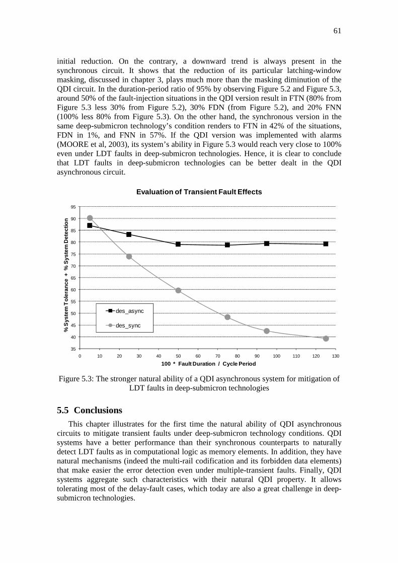
61
initial reduction. On the contrary, a downward trend is always present in the synchronous circuit. It shows that the reduction of its particular latching-window masking, discussed in chapter 3, plays much more than the masking diminution of the QDI circuit. In the duration-period ratio of 95% by observing Figure 5.2 and Figure 5.3, around 50% of the fault-injection situations in the QDI version result in FTN (80% from Figure 5.3 less 30% from Figure 5.2), 30% FDN (from Figure 5.2), and 20% FNN (100% less 80% from Figure 5.3). On the other hand, the synchronous version in the same deep-submicron technology’s condition renders to FTN in 42% of the situations, FDN in 1%, and FNN in 57%. If the QDI version was implemented with alarms (MOORE et al, 2003), its system’s ability in Figure 5.3 would reach very close to 100% even under LDT faults in deep-submicron technologies. Hence, it is clear to conclude that LDT faults in deep-submicron technologies can be better dealt in the QDI asynchronous circuit.
Figure 5.3: The stronger natural ability of a QDI asynchronous system for mitigation of
LDT faults in deep-submicron technologies
5.5 Conclusions This chapter illustrates for the first time the natural ability of QDI asynchronous
circuits to mitigate transient faults under deep-submicron technology conditions. QDI systems have a better performance than their synchronous counterparts to naturally detect LDT faults as in computational logic as memory elements. In addition, they have natural mechanisms (indeed the multi-rail codification and its forbidden data elements) that make easier the error detection even under multiple-transient faults. Finally, QDI systems aggregate such characteristics with their natural QDI property. It allows tolerating most of the delay-fault cases, which today are also a great challenge in deep-submicron technologies.
35
40
45
50
55
60
65
70
75
80
85
90
95
0 10 20 30 40 50 60 70 80 90 100 110 120 130
% S
yste
m T
oler
ance
+ %
Sys
tem
Det
ectio
n
100 * Fault Duration / Cycle Period
Evaluation of Transient Fault Effects
des_async
des_sync

62

6 TECHNIQUES FOR TRANSIENT-FAULT MITIGATION
The level of immunity to physical failures and fabrication defects (discussed in chapter 3) define the IC’s reliability (KRISHNAMOHAN; MAHAPATRA, 2004). As the technology evolutions have increased the vulnerability to such effects, the circuits’ reliability has thus been greatly affected. Nevertheless, IC-embedded skills can improve the robustness (resistance) to such effects in order to reach satisfactory reliabilities.
The IC’s robustness is normally increased by the implementation of protection mechanisms based on mitigation techniques. In the last years many techniques have been proposed to mitigate transient faults. There are several options for the different abstraction levels of a design. In fact, nowadays any commercial low-complexity IC had, at least at one abstraction level of its design, the implementation of a technique to mitigate transient faults.
Techniques for transient-fault mitigation can thus be classified according to the usual abstraction levels of a design, which are detailed in chapter 4. This thesis divides the techniques at low and high abstraction level.
The techniques at low abstraction level are developed at real-circuit level, electrical, logical, or RT levels. Iyer (2005), Lima (2003-b), Kastensmidt (2006), and many other authors list such low-level protection approaches as: advanced fabrication technologies produced by specific physical processes like silicon-on-insulator (SOI); IC package shielding; layout mask modifications; transistor sizing; transistor insertion; schemes of robust memory cells; spatial or temporal hardware redundancy; hardware codifications for error detection or correction; or any combination of these techniques.
On the other hand, the techniques at high abstraction level are those ones implemented at algorithmic or systemic levels. Iyer (2005), Lisboa (2009), and several other works cite such techniques as: hardware modules dedicated to the detection or correction of errors; spatial or temporal hardware redundancy; spatial or temporal software redundancy; software codifications for error detection or correction; hybrid approaches combining hardware and software; or even any combination of these techniques.
The implementation of any mitigation technique inherently increases the design costs. However, such costs in terms of area, power consumption, performance, and development (i.e., designers, design time, and fabrication) vary depending on the technique choice as well as the target reliability (e.g., if design will operate in space or on earth). Hence, a careful evaluation of the technique characteristics in accordance with the design goals is always essential.
For this reason too, the scientific community has done in the last decades enormous efforts to efficiently increase the synchronous systems’ reliability. Concerning transient-

64
fault effects, there are several techniques for soft-error mitigation. Many of them have been designed to protect the system only against transient faults arisen in memory elements, in which cause thus the direct soft errors. However, in recent years as a result of the deep-submicron-technology challenges, several other techniques have been developed to protect the system also against transient faults arisen in combinational circuits, which may propagate them to memory elements and thus generating the indirect soft errors. Most of these techniques for soft-error mitigation are dedicated to synchronous systems (MONNET, 2007-a). Hence, in order to optimally make even more robust asynchronous systems, specific techniques for them have also been developed.
According to the purposes of this thesis, the following sections discuss the main transient-fault mitigation techniques at logical, RT, and electrical levels. The few alternatives for QDI asynchronous circuits are also discussed. In addition, the costs of mitigation techniques applied at different abstraction levels are analyzed based on experimental area-overhead results of complex synchronous systems.
6.1 Techniques at Logical and RT Abstraction Levels Hardware-implemented techniques based on redundancy in space or time,
codifications for error detection or correction, or any combination of these ones can be designed at different abstraction levels. However, most of them are usually designed at logical and RT abstraction levels because thus there is a trade-off between the development costs and system’s overheads, as further explained in section 6.3.
6.1.1 Classic Spatial Redundancies
The generic principle of hardware-implemented techniques based on spatial redundancy is to replicate parts of the circuit and introducing a comparator element. This element is able to indicate any eventual difference in the results of the parts as a consequence of the fault occurrence on one of them.
The simplest redundancy scheme is the duplication with comparison (DWC), which allows only error detection (WAKERLY, 1978). Hence, a recomputation must necessarily be performed for the error correction. In fact, there are several techniques derived from the DWC, like those presented by Nicolaidis (1999), Anghel (2000-a), Lima (2003-a), Almukhaizim (2003); Monnet (2005-b).
Nicolaidis (1999) suggests DWC using a dynamic C-element only as a comparator of the redundant combinational circuits’ results. This memory element (C-element), which the author names as CWSP (Code Word State Preserving), is indeed inserted on the circuit data path. It allows as detection as correction by filtering the transient faults arisen in combinational circuits. It means no recomputation is required. This CWSP scheme thus prevents the generation of indirect soft errors by the cost in performance equals to, at least, the CWSP circuit’s delay plus the transient fault duration.
On the other hand, triple or superior redundancies are able to detect and also correct direct soft errors through a purely combinational voter element. The most classic of them is the well-known triple modular redundancy (TMR) (HENTSCHKE et al, 2002). The TMR principle is traditional due to its simplicity and good efficiency for error detection and correction. A common TMR application is to protect registers as shown in Figure 6.1.

65
Figure 6.1: TMR scheme applied on a 1-bit register
Such techniques, which are based on comparison of N redundant parts, always operate properly only if N-1 parts, at least, are free of faults. Hence, multiple-fault occurrences, which although are cases of low probability, may affect redundant parts at the same time, and thus the techniques may fail to accomplish the fault mitigation.
The triple redundancy (TMR) of a system ensures, nevertheless, a considerable reliability. However, the costs in terms of area are evident and greater than 200%. The performance is affected basically by the voter element’s delay. On the other hand, the double redundancy (DWC) of a system would imply cost in terms of area greater than 100%, and the performance would suffer penalties as a consequence of the recomputations for correction. Even if a logical-level DWC scheme by CWSP in (NICOLAIDIS, 1999) could be applied to prevent such recomputations, it would work to avoid only indirect soft errors. Direct soft errors in memory circuits would not be detected by this logical-level approach by CWSP. Furthermore, the recomputations also would hinder the reuse of system’s software applications, since the code instructions would need to consider the extra cycles generated due to the fault occurrences.
The option to apply TMR only in certain critical parts of the system, like its memory components, reduces greatly such overheads in terms of area and performance. In addition, the system ensures a good reliability because it becomes robust to direct soft errors. The only vulnerability related to direct soft errors is limited to occurrences of lower probability in which simultaneous transient faults on two or three of the redundant memory elements disrupt the voter circuit’s results. The work in (BASTOS, 2009-c) shows through three different commercial microprocessors that protecting only their registers by TMR reduces largely the costs in terms of area, performance, and software application development. The overheads in area of the robust microprocessors reach 109% to 43% larger than the area of the non-protected systems. The penalties in clock frequency are between 9% and 6%. Moreover, the reuse of software applications is always feasible.
6.1.2 Temporal Redundancies
If applying TMR only in memory elements ensures a system with considerable robustness to direct soft errors, the same cannot be said for indirect soft errors. A transient fault arisen in combinational circuit could spread to the three redundant
Com
bina
tiona
l Blo
ck
Nex
t Com
bina
tiona
l Blo
ck
Voter
Reg
iste
r
Reg
iste
r
Reg
iste
r

66
memory elements and thus causing simultaneously three indirect soft errors. The voter, therefore, could not detect them. From such a need to tolerate indirect soft errors that the hardware-implemented techniques based on temporal redundancy began to be proposed by Nicolaidis (1999).
The basic temporal redundancy’s principle is evaluating the data in different instants. It allows the detection of faults which have a temporal nature like the transient ones. The implementation of such a principle requires the addition of an element able to retain the data at past instant to compare them with data at the present instant. Nicolaidis (1999) suggests as retention element a simple delay block that would be implemented, for example, by buffers at the combinational circuits’ outputs. A double temporal redundancy is thus characterized and therefore a temporal DWC can be implemented to mitigate indirect soft errors by using the same CWSP scheme discussed in previous section for a spatial DWC. Figure 6.2 and Figure 6.3 illustrate such a so-called scheme of time redundancy (TR), where DDelay_Block and DCWSP are the propagation times of the blocks and WMax_SET is the maximum transient-fault duration tolerated at the output of a combinational circuit. The CWSP circuit in Figure 6.2 is an asynchronous sequential machine characterizing a C-element implemented by combinational standard logic gates. The logic function of a C-element is discussed in chapter 2. Nicolaidis (1999) also suggests CWSP elements that work as logic to replace the last logic gates of a combinational circuit like shown in Figure 6.4. In addition, more optimized CWSP versions at electrical level are also proposed, as discussed in last sections of this chapter.
The small cost in area to implement the TR+CWSP scheme in Figure 6.2 is basically due to the CWSP elements and the buffers or inverters used to characterize the delay blocks. On the other hand, the performance can be quite affected depending on the target maximum transient-fault width (WMax_SET) wanted to be tolerated. In fact, WMax_SET must be lesser than the propagation time of the delay block (DDelay_Block), so as larger as the WMax_SET is, the penalty in DDelay_Block and thus also in performance is worse. The work in (BASTOS, 2006-e) shows indeed that this penalty is at least twice greater than DDelay_Block.
Figure 6.2: TR+CWSP scheme applied on a 1-bit register
Com
bina
tiona
l Blo
ck
Nex
t Com
bina
tiona
l Blo
ck
Reg
iste
r
CWSP
Del
ay
Identity
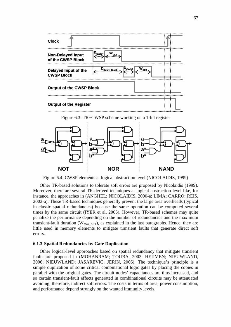
67
Figure 6.3: TR+CWSP scheme working on a 1-bit register
Figure 6.4: CWSP elements at logical abstraction level (NICOLAIDIS, 1999)
Other TR-based solutions to tolerate soft errors are proposed by Nicolaidis (1999). Moreover, there are several TR-derived techniques at logical abstraction level like, for instance, the approaches in (ANGHEL; NICOLAIDIS, 2000-a; LIMA; CARRO; REIS, 2003-a). These TR-based techniques generally prevent the large area overheads (typical in classic spatial redundancies) because the same operation can be computed several times by the same circuit (IYER et al, 2005). However, TR-based schemes may quite penalize the performance depending on the number of redundancies and the maximum transient-fault duration (WMax_SET), as explained in the last paragraphs. Hence, they are little used in memory elements to mitigate transient faults that generate direct soft errors.
6.1.3 Spatial Redundancies by Gate Duplication
Other logical-level approaches based on spatial redundancy that mitigate transient faults are proposed in (MOHANRAM; TOUBA, 2003; HEIJMEN; NIEUWLAND, 2006; NIEUWLAND; JASAREVIC; JERIN, 2006). The technique’s principle is a simple duplication of some critical combinational logic gates by placing the copies in parallel with the original gates. The circuit nodes’ capacitances are thus increased, and so certain transient-fault effects generated in combinational circuits may be attenuated avoiding, therefore, indirect soft errors. The costs in terms of area, power consumption, and performance depend strongly on the wanted immunity levels.
Non-Delayed Inputof the CWSP Block
Clock
Output of the Register
Delayed Input of theCWSP Block
Output of the CWSP Block
DDelay_Block
WSETDCWSP
DCWSP WSET
Non-Delayed Inputof the CWSP Block
Clock
Output of the Register
Delayed Input of theCWSP Block
Output of the CWSP Block
DDelay_Block
WSETDCWSP
DCWSP WSET
NOT NOR NAND
a
a*
a
a* b*
b a
a* b*
b

68
6.1.4 Spatial Redundancies by Codification
There are many mitigation techniques that apply spatial redundancy to encode the data and thus obtaining codes for detection or correction. The most traditional of them and also the most used in commercial ICs is the codification by parity from which several other techniques like, for instance, those shown in (SOGOMONYAN, 1974; ALMUKHAIZIM; MAKRIS, 2003; LISBOA; CARRO, 2008; PFLANZ et al, 2002; PAPADOMANOLAKIS et al, 2001) are derived.
More sophisticated techniques known as error detection and correction (EDAC) codes include the Reed Solomon code, the Hamming code, and several derivations of them like, for instance, those proposed in (NEUBERGER et al, 2003; NEUBERGER; LIMA; REIS, 2005; ARGYRIDES, 2007).
The codification by parity or EDAC codes are more effective for groups of memory elements or memory arrays such as caches and register files (HENTSCHKE et al, 2002; IYER et al, 2005). In fact, the costs to encode the circuit are amortized over the array size. On the other hand, the use of such codes in individual microprocessor registers, for instance, may imply enormous penalties. For the sake of it, Hentschke (2002) compared the Hamming code with the traditional TMR. His results show that the Hamming code is more suitable for use in access buses to groups of storage cells (e.g., RAM), while the TMR is more appropriate to protect individual registers (e.g., CPU registers).
The codifications are thus usually used to mitigate direct soft errors, however recently the Hamming code was investigated (LISBOA, 2009) to protect also combinational circuits and therefore mitigating eventual indirect soft errors. Such an investigation shows better results in terms of area, power consumption, and performance than the TMR application in combinational circuits.
Furthermore, the data codifications M-out-of-N, discussed in chapter 2, are also spatial redundancy forms which consist of N redundant wires to represent a data bit. In the simplest and most traditional case, the codification 1-out-of-2 (dual rail) has four codification states to represent two logic values (0 or 1). Any transient-fault occurrence, therefore, may switch the data to non-existent states and thus both direct and indirect soft errors can be detected. The approaches M-out-of-N are not only for asynchronous circuits, although they have little use in applications of synchronous circuits.
6.1.5 Techniques Dedicated to QDI Asynchronous Circuits
Even though most of the techniques described above can be implemented in QDI asynchronous systems, they were designed mostly based on the time limitation of a clock. On the other hand, as presented in chapter 2, a QDI circuit has natural robustness properties due to its data codification, communication protocol, and quasi-delay insensitivity, and thus it already has certain inherent mitigation techniques.
Concerning the natural transient-fault robustness, a fault event may potentially perturb the communication protocol and leading the system, for instance, to a deadlock, which is indeed easily detectable (PISETRAK, 1995; MONNET, 2007-a), as discussed in chapter 5. In this sense, in order to take advantage of such a natural redundancy, techniques particularly dedicated to QDI circuits would optimize significantly the designs which aim at achieving higher levels of transient-fault immunity.
There are several mitigation techniques dedicated to QDI asynchronous circuits’ subclasses (SAWIN; MAKI, 1974; VERDEL; MAKRIS, 2002; GARDINER, 2007;

69
KUANG, 2007; ALMUKHAIZIM; SHI; MAKRIS, 2008; KUANG et al, 2010), which are indeed less-robust variations of the original ones detailed in chapter 2. However, specific techniques for pure QDI circuits, there are still very few as described in the following paragraphs.
Simple very-low-cost approaches for detection are similarly proposed in (DAVID; GINOSAR, YOEL, 1995, MOORE, 2002, 2003, YANG et al, 2003) by taking advantage of the QDI circuits’ redundancy qualities. Moore (2002) considers a dual-rail system using the four-phase protocol and the codification by three states explained in chapter 2. The author assumes that a data flow’s deadlock happens in the situations in which the allowed codification states switch like 01=>00, 10=>00, 00=>10, or 00=>01 due to an event of a fault, and therefore the errors generated are easily detectable. On the other hand, in the situations in which states change for forbidden states (01=>11 or 10=>11), the circuit reports wrong values, but no deadlock happens and therefore it is not detectable. The author thus proposes a circuit to keep on with such an alarm 11 as a way to ensure the system’s deadlock. The alarm code 11 could not, therefore, disappear in subsequent computation iterations, and so it would enable the system to detect these errors. Even if this technique can detect both indirect and direct soft error, it does not guarantee the detection of all possible transient-fault effects. In fact, the switches to allowed states, discussed above, do not always generate deadlock, and therefore they are not always detectable (MONNET, 2007-a, 2007-b).
LaFrieda (2004) proposes error-detection mechanisms at RT level of a QDI system design, moreover techniques at electrical level to prevent eventual delay faults on isochronic forks are also suggested. For detection of indirect or direct soft errors as well permanent-fault effects, the author follows the Moore’s idea (2002) which transforms errors into system’s deadlocks. However, he suggests doubling the synchronization signals that are used for request and acknowledgment between system’s stages. For protection of the data signals, additional C-elements are used to synchronize the bits of a data word and so making by groups the data reading or writing between system’s stages. Unfortunately, these detection techniques impose severe overheads on the system if they are applied on all circuit parts, especially in terms of area.
Peng (2005) presents a half buffer, which is a macrocell commonly used as QDI systems’ memory block, able to make a system’s deadlock when errors happen due to transient or permanent faults. The scheme can mitigate as direct as indirect soft error. The cost in area is practically a duplication, and the penalty in performance is small. The author also suggests a detector of system’s deadlock to determine the most appropriate instant to perform a recomputation for error correction.
Another technique at RT level dedicated to mitigate indirect and direct soft errors is proposed by Jang (2005). The basic principle is duplicating all blocks of the system’s stages and synchronizing the duplicated outputs by two additional C-elements. In fact, a circuit block would pass to have duplicated inputs and outputs. This approach thus provides enormous penalties in terms of area and also performance, even more severe than the LaFrieda’s techniques (2004).
Monnet (2005-b) suggests three techniques to mitigate indirect and direct soft errors in QDI systems. In one of them, only the computational block of a stage is duplicated as shown in Figure 6.5. The memory block is modified replacing, for example, the two-input C-elements by other ones of three inputs. It increases the transient-fault masking effects and thus also the circuit robustness. As this technique implies in duplicating the
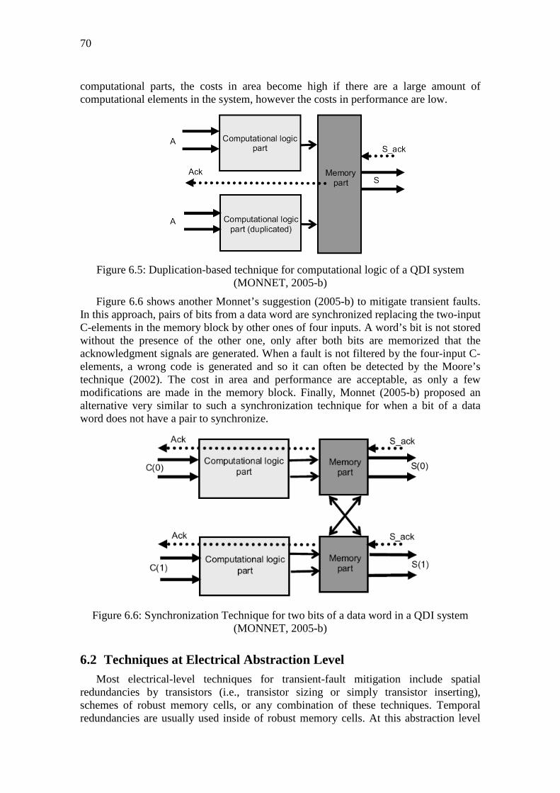
70
computational parts, the costs in area become high if there are a large amount of computational elements in the system, however the costs in performance are low.
Figure 6.5: Duplication-based technique for computational logic of a QDI system (MONNET, 2005-b)
Figure 6.6 shows another Monnet’s suggestion (2005-b) to mitigate transient faults. In this approach, pairs of bits from a data word are synchronized replacing the two-input C-elements in the memory block by other ones of four inputs. A word’s bit is not stored without the presence of the other one, only after both bits are memorized that the acknowledgment signals are generated. When a fault is not filtered by the four-input C-elements, a wrong code is generated and so it can often be detected by the Moore’s technique (2002). The cost in area and performance are acceptable, as only a few modifications are made in the memory block. Finally, Monnet (2005-b) proposed an alternative very similar to such a synchronization technique for when a bit of a data word does not have a pair to synchronize.
Figure 6.6: Synchronization Technique for two bits of a data word in a QDI system (MONNET, 2005-b)
6.2 Techniques at Electrical Abstraction Level Most electrical-level techniques for transient-fault mitigation include spatial
redundancies by transistors (i.e., transistor sizing or simply transistor inserting), schemes of robust memory cells, or any combination of these techniques. Temporal redundancies are usually used inside of robust memory cells. At this abstraction level

71
there are no techniques dedicated exclusively to mitigate transient faults in QDI asynchronous circuits. In fact, many transistor-based spatial redundancies initially proposed in synchronous circuits are also applicable in QDI circuits. On the other hand, there are several schemes of robust memory cells that depend on a clock signal and, therefore, are specific to synchronous circuits.
6.2.1 Spatial Redundancies by Transistors
These techniques consist basically of handling transistors in terms of their sizes or simply including redundancy. The idea is producing schemes that allow transient-fault mitigation by attenuation, total tolerance or even detection. Most of them focus on the mitigation of indirect soft errors, although they can be also used to mitigate direct soft errors.
Nicolaidis (1999) suggests duplicating the transistors of standard logic gates in order to implement the functional characteristics of a CWSP element (discussed at logical level in previous sections). Such Nicolaidis’s electrical-level approaches (1999), detailed in Figure 6.7, considerably reduce the number of required transistors in relation to their equivalent logical-level designs shown in Figure 6.4. Nevertheless, technological trends may prevent the correct operation of such an approach due to the high number of CMOS transistors in series.
Figure 6.7: CWSP elements at electrical abstraction level (NICOLAIDIS, 1999)
Some techniques seek to mitigate the transient-fault effects by sizing properly the logic gates’ transistors (ZHOU; MOHANRAM, 2004; DHILLON et al, 2004; CAZEAUX et al, 2005; ZHOU; MOHANRAM, 2006; RAO; BLAAUW; SYLVESTER, 2006). Techniques based on symmetric and asymmetric transistor sizing are discussed in (LAZZARI et al, 2007-a; LAZZARI, 2007-b; ASSIS et al, 2009-a; ASSIS, 2009-b). The idea of these approaches is increasing the sizes of certain transistors, mostly in terms of channel width, in order to add capacitance in critical circuit nodes. The minimum charges required to upset a circuit thus become larger by increasing the node capacities to attenuate transient faults.
a*
a
a
a*
b
b*
a
a*
b
b* a
a*
b
b*
a
a*
b
b*
NOT NOR NAND

72
The transistor sizing techniques allow a greater control on adjusting the node capacitance values, hence they can penalize less the circuit design than the gate duplication approach discussed in previous section. However, as the gate duplication, such penalties depend strongly on the immunity level required by the circuit applications (e.g., if the circuit will operate in space or on earth).
Using the same idea of increasing the critical circuit nodes’ capacitances, other techniques modify only the form used to control, in terms of design, the capacitance values. Assis (2009-a, 2009-b) discusses the circuit ability to mitigate soft errors by the use of folding, which doubles the transistors but divides their sizes by placing them in parallel. Karnik et al. (2002) proposes adding an explicit capacitor on the weakest circuit nodes through the insertion of capacitors built by NMOS and PMOS transistors. Transistor-based schemes that make low-pass filters to filter out transients, especially the short duration transients, are proposed in (KUMAR; TAHOORI, 2005; SASAKI; NAMBA; ITO, 2006, 2008; UEMURA et al, 2008) by using pass transistors, Schmitt trigger, or C-elements.
Other transient-fault mitigation approaches propose detection schemes for direct and indirect soft errors based on current sensors (NDAI et al, 2005; NETO et al, 2006-a, 2006-b; LISBOA et al, 2007-b). These detection techniques result in small system’s overheads, however they require error-correction methods at higher abstraction levels.
6.2.2 Robust Memory Cells
Many schemes of robust memory cells were proposed mostly to mitigate direct soft errors like, for instance, those ones presented in (CALIN; NICOLAIDIS; VELAZCO, 1996; KARNIK et al, 2002; KOMATSU et al, 2004; ZHANG; SHANBHAG, 2005; KRISHNAMOHAN, MAHAPATRA, 2005; SASAKI; NAMBA; ITO, 2006; FAZELI et al, 2007; SASAKI; NAMBA; ITO, 2008; UEMURA et al, 2008).
Omaña (2003; 2007) suggests a latch doubling its feedback loop as shown in Figure 6.8. Such a robust latch thus results in small system’s overheads. However, if its output load is not significant, its output node remains vulnerable even to short duration transients. Robust cell alternatives based on temporal redundancy are proposed in (KRISHNAMOHAN, MAHAPATRA, 2004; LAZZARI; ANGHEL; REIS, 2005). Most of these robust memory cells include extra transistors on the data path, so they naturally increase the system’s overheads. Moreover, they often implement redundancies that add to the circuit more nodes vulnerable to transient faults.
Figure 6.8: A robust latch (OMAÑA, 2007)

73
6.3 Costs of Mitigation Techniques at Different Abstraction Levels Techniques implemented at higher abstraction levels of a design are more
advantageous in terms of development costs (i.e., designers, design time, and fabrication). However, they are naturally more expensive in terms of system’s overheads (i.e., costs in area redundancy, power consumption, or performance). At lower abstraction levels, the design is more optimized because is done through smaller area slices that enable working more details. For instance, a cell from a library of gates is optimized at lower levels. However, the design requires a larger effort and elaboration time of the designers, so the development costs are greater. Figure 6.9 summarizes such trends by showing generically the system’s overheads in function of the development costs.
Figure 6.9: Costs of mitigation techniques at different abstraction levels
Such an idea was shown in (BASTOS, 2009-c) through the protection of microprocessors against transient faults as in memory as in combinational blocks. This work analyzed the area costs per register’s bit, and so an area overhead extrapolation could be done for any synchronous architecture. The results showed thus that the area of each register’s bit on any microprocessor is increased by a factor of 9 using a certain RT-level protection scheme, which is based on traditional mitigation techniques. Otherwise, using a similar scheme at electrical level, it is increased by 5. Figure 6.10 summarizes these results through different commercial synchronous systems. It shows that such mitigation techniques, which were used in (BASTOS, 2009-c) aiming to avoid recomputation, have lower area overheads by implementing at electrical level than at RT level. Obviously, as the protection scheme is to mitigate transient faults, such an area overhead increases in function of the memory area’s size, that is the sensitive zone to be protected. Nevertheless, the design development of a RT-level protection scheme, which can be reusable by register’s bit, is much simpler and faster than at electrical level.
System’s overheads (area,
performance, orpower consumption)
Costs of development (designers,
time-to-market, or fabrication)
Techniques at the Lowest Abstraction
Level
Techniques at the Highest Abstraction
Level
They are not able to detect all possibilities
of errors!
Techniques at Intermediary Levels
Most of cases, they do not ensure the target IC reliability.
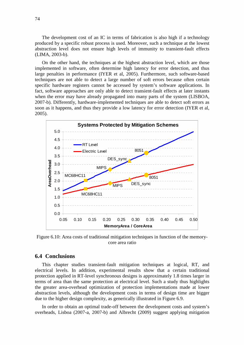
74
The development cost of an IC in terms of fabrication is also high if a technology produced by a specific robust process is used. Moreover, such a technique at the lowest abstraction level does not ensure high levels of immunity to transient-fault effects (LIMA, 2003-b).
On the other hand, the techniques at the highest abstraction level, which are those implemented in software, often determine high latency for error detection, and thus large penalties in performance (IYER et al, 2005). Furthermore, such software-based techniques are not able to detect a large number of soft errors because often certain specific hardware registers cannot be accessed by system’s software applications. In fact, software approaches are only able to detect transient-fault effects at later instants when the error may have already propagated into many parts of the system (LISBOA, 2007-b). Differently, hardware-implemented techniques are able to detect soft errors as soon as it happens, and thus they provide a low latency for error detection (IYER et al, 2005).
Figure 6.10: Area costs of traditional mitigation techniques in function of the memory-core area ratio
6.4 Conclusions This chapter studies transient-fault mitigation techniques at logical, RT, and
electrical levels. In addition, experimental results show that a certain traditional protection applied in RT-level synchronous designs is approximately 1.8 times larger in terms of area than the same protection at electrical level. Such a study thus highlights the greater area-overhead optimization of protection implementations made at lower abstraction levels, although the development costs in terms of design time are bigger due to the higher design complexity, as generically illustrated in Figure 6.9.
In order to obtain an optimal trade-off between the development costs and system’s overheads, Lisboa (2007-a, 2007-b) and Albrecht (2009) suggest applying mitigation
Systems Protected by Mitigation Schemes
DES_sync
MIPS
MC68HC11
8051
MIPS
MC68HC11
DES_sync
8051
0.0
0.5
1.0
1.5
2.0
2.5
3.0
3.5
4.0
4.5
5.0
0.05 0.10 0.15 0.20 0.25 0.30 0.35 0.40 0.45 0.50
MemoryArea / CoreArea
Are
aOve
rhea
d
RT Level
Electric Level

75
techniques at different abstraction levels of the design to cope with the recent challenges imposed by nanometer technologies. Lisboa (2009) points out that most of the current mitigation techniques implement too many costs in terms of performance, area or power consumption to tolerate certain transient-fault effects. In fact, he puts a question about those effects on deep-submicron technologies that may last longer than a clock cycle. Lisboa (2009) thus suggests low-cost alternatives proposing mitigation techniques especially at higher abstraction levels. Moreover, Albrecht (2009) also recommends that the error detection should be performed at lower abstraction levels of SOC designs, while the error correction at higher abstraction levels. Such an idea is quite pertinent, since lower levels offer greater ability to detect fault effects. Furthermore, the system’s overheads due to the implementation of error-detection mechanisms at these levels are naturally lower than alternatives at higher levels. About the error correction at such higher abstraction levels, the simple procedure is to perform the recomputation, which can add, through extra execution cycles, a high latency to the system. However, the low probability of transient-fault occurrence does such a recomputation cost become almost negligible (LISBOA, 2009).
Albrecht (2009) and Lisboa (2007-a, 2007-b, 2009) do not discuss an alternative that is naturally robust to many deep-submicron-technology challenges: the design of QDI asynchronous systems. This design style requires no additional mitigation mechanisms to achieve satisfactory IC reliability. In these QDI circuits, the long duration transient (LDT) faults in deep-submicron technologies, as defined by Lisboa (2007-a), have no the same aggravating effects than in synchronous circuits. In fact, as there is no a clock’s fixed timing reference, as longer as the transient duration is, the QDI systems have a larger natural ability to detect it. Chapter 5 of this thesis shows that such an absence of a clock to control the data flow, the multi-rail data codification, and the handshaking asynchronous communication protocol induce the system more easily to the deadlock by facing longer transients. A QDI system thus has a high potential to detect such transient-fault effects.
This intrinsic robustness characteristic of QDI circuits, therefore, coincides with the Albrecht’s idea (2009), which is the best approach today to face efficiently with the deep-submicron-technology drawbacks, i.e. performing the detection at lower abstraction levels. Moreover, a QDI system has other natural qualities which aggregate most notably its high modularity, low power consumption, large insensitivity to delay variations, high confidentiality, and low noise emission. All of these properties indeed are naturally taken into account during the design development without using any additional specific technique. Therefore, lower development efforts and shorter design time (i.e., faster time-to-market) can be achieved when the design goal is to have such properties. Obviously, it still depends on a greater commercial development of asynchronous-dedicated EDA tools, as discussed in chapter 2. Furthermore, a QDI circuit with such various benefits can even present a performance at least similar to its synchronous counterpart by only paying for around a twice larger area. On the other hand, synchronous systems, which are devoid of these natural QDI system’s qualities, indeed would require much more area overheads to achieve these same benefits. Figure 6.10, that lists complex synchronous systems, already details large area overheads only for mitigation of short duration transient faults. Imaging the protection against LDT faults, delay faults, and security attacks would certainly increase such costs.

76

7 EVALUATING TRANSIENT-FAULT EFFECTS ON C-ELEMENT’S IMPLEMENTATIONS
C-element cells, outlined in chapter 2, have a high importance to implement more robust systems. They have been used even to protect synchronous circuits against transient faults (NICOLAIDIS, 1999; MITRA et al, 2005; FAZELI et al, 2007). Actually, their filter ability allows mitigating transient faults, and so avoiding SE occurrences. However, in QDI asynchronous circuits, the C-elements are also used to implement memory blocks, and then they are also directly sensitive to SEs.
On the other hand, most of the SE cases in QDI asynchronous systems are naturally mitigated. As chapter 3, 4, and 5 discusses, such systems have intrinsically a good capacity for transient-fault tolerance and an excellent ability for detection of failures arisen from LDT faults. Then, a simple way to further increase the QDI systems’ robustness is improving the transient-fault tolerances of their C-elements, which by nature already have filter abilities, and thus avoiding SE occurrences that would result in failures. Such a solution would prevent recomputations for recovering the system (correction process in FDN cases discussed in chapter 3). Furthermore, it could also prevent the few FNN cases that are not able to be mitigated by alarm mechanisms as highlighted in chapter 5.
The design of a QDI circuit can be accomplished through various traditional C-element’s implementations at electrical level of abstraction. Therefore, the QDI system’s design can be done by the selection of implementation options that have mostly stronger abilities to tolerate shorter-duration transient faults, since longer-duration transient faults are costly to be tolerated but are easily detectable at higher abstraction levels of a QDI system. The QDI system’s C-elements would thus have a better capacity for transient-fault tolerance, and so the system would be even more transient-fault robust.
In order to obtain the best C-element’s implementation options in terms of transient-fault robustness as well as in terms of costs in area, performance, and power consumption, a novel methodology to evaluate at electrical level is required. Indeed, it is necessary due to the C-element function’s particularities for asynchronous systems that require an also particular method to assess the transient-fault effects on their C-element circuit’s nodes. The existing methods for evaluation of such effects on memory cells, for instance, are dedicated to clocked circuits, and thus they are so dependent on the clock-timing characteristics (OMAÑA; ROSSI; METRA, 2007).
Hence, the following sections propose a novel solution discussed also in (BASTOS et al, IOLTS 2010-b). Unlike related work in (VAIDYANATHAN et al, 2006), the new methodology explained in this chapter presents and evaluates all situations of transient-

78
fault vulnerability on the traditional C-element’s versions for asynchronous systems. The proposed method for electrical-level evaluation considers C-element’s implementations designed under similar conditions. The concept of perturbation’s charge is introduced and used to evaluate the C-element versions’ robustness. Moreover, this chapter also suggests the application of electrical-level mitigation techniques in the C-element’s versions to obtain them further transient-fault robust. The best C-element’s options to design even more transient-fault robust systems are thus innovatively presented (BASTOS et al, IOLTS 2010-b).
7.1 Traditional C-element’s Implementations The dual-behaviour function of a C-element, either buffer or memory cell, is further
explained in chapter 2.
If the C-element is implemented by combinational standard cells, no optimal circuit areas are achieved (MAURINE et al, 2003; FOLCO et al, 2005). Thus, it is mandatory to use customized implementations like those traditional ones discussed in (SHAMS; EBERGEN; ELMASRY, 1998). The basic version detailed in Figure 7.1 (A) is a dynamic implementation, which preserves the steady state of output just during a while. Especially for QDI circuits, this dynamic version is not interesting, since there is not a keeper circuit to ensure the steady state of output until the next event driver of identical inputs. In contrast, the three traditional static implementations illustrated in Figure 7.1 (B) (C) (D) work with such a keeper circuit.
Figure 7.1: The traditional C-element’s implementations
The designs of these traditional C-element cells can be sized by using the minimum channel length of a CMOS technology. The diffusion widths of the PMOS and NMOS transistors can be defined in accordance with the equations below, where Wmin is the minimum diffusion width in the target CMOS technology, and fPMOS is the factor that produces a C-element cell providing a voltage output of similar rise and fall times. Such a factor fPMOS works thus to compensate the PMOS transistors, which are physically
n3
n2
(A) Dynamic
n4 n10
WP4
WN4
n0
n1
WPE
WPI
WNI
WNEn1
n0
n4 n10
WP4
WN4
Wmin
Wmin
n0
n1
WPE
WPI
WNI
WNEn1
n0
n0 n1Wmin Wmin
n0n1Wmin Wmin
n6
n7
n4 n10
WP4
WN4
Wmin
Wminn0
n1
WPE
WPI
WNI
WNEn1
n0
(B) Conventional
(D) Weak Feedback(C) Symmetric
n4 n10
WP4
WN4
Wmin
Wmin
n1
n0
WNE/2
WNI/2
WPI/2
WPE/2
n1
n0
n0
n1
WPE/2
WPI/2
WNI/2
WNE/2n1
n0
n2 n20
n3 n21
n2
n3
n2
n3
n3
n2
(A) Dynamic
n4 n10
WP4
WN4
n0
n1
WPE
WPI
WNI
WNEn1
n0
n4 n10
WP4
WN4
Wmin
Wmin
n0
n1
WPE
WPI
WNI
WNEn1
n0
n0 n1Wmin Wmin
n0n1Wmin Wmin
n6
n7
n4 n10
WP4
WN4
Wmin
Wminn0
n1
WPE
WPI
WNI
WNEn1
n0
(B) Conventional
(D) Weak Feedback(C) Symmetric
n4 n10
WP4
WN4
Wmin
Wmin
n1
n0
WNE/2
WNI/2
WPI/2
WPE/2
n1
n0
n0
n1
WPE/2
WPI/2
WNI/2
WNE/2n1
n0
n2 n20
n3 n21
n2
n3
n2
n3
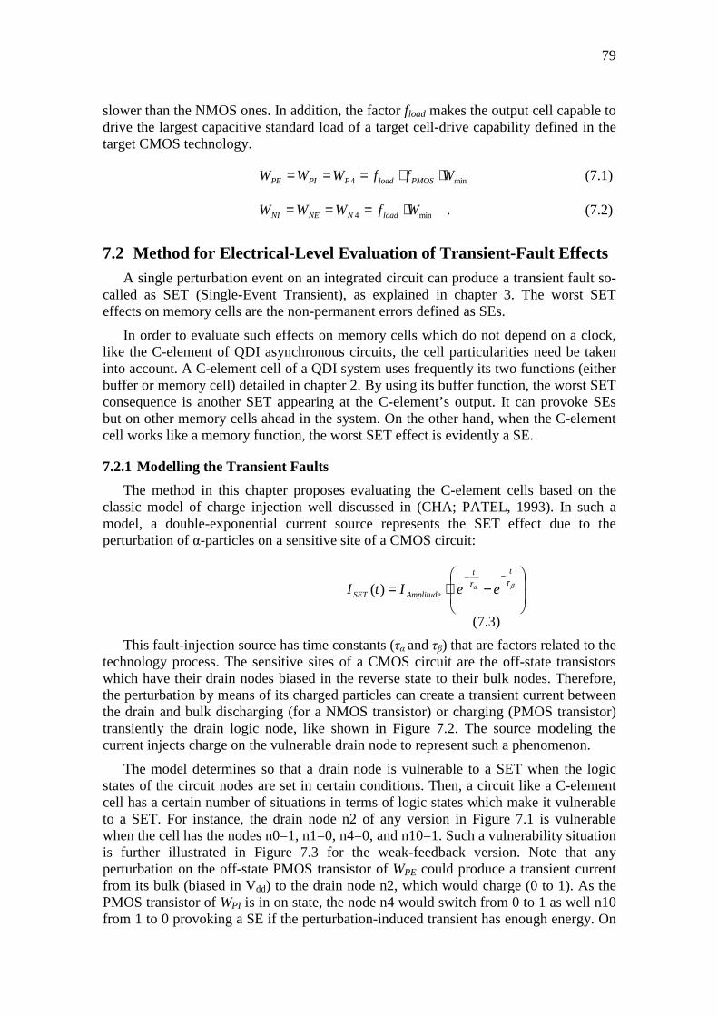
79
slower than the NMOS ones. In addition, the factor fload makes the output cell capable to drive the largest capacitive standard load of a target cell-drive capability defined in the target CMOS technology.
min4 WffWWW PMOSloadPPIPE ⋅⋅=== � (7.1)
min4 WfWWW loadNNENI ⋅=== �. (7.2)
7.2 Method for Electrical-Level Evaluation of Transient-Fault Effects A single perturbation event on an integrated circuit can produce a transient fault so-
called as SET (Single-Event Transient), as explained in chapter 3. The worst SET effects on memory cells are the non-permanent errors defined as SEs.
In order to evaluate such effects on memory cells which do not depend on a clock, like the C-element of QDI asynchronous circuits, the cell particularities need be taken into account. A C-element cell of a QDI system uses frequently its two functions (either buffer or memory cell) detailed in chapter 2. By using its buffer function, the worst SET consequence is another SET appearing at the C-element’s output. It can provoke SEs but on other memory cells ahead in the system. On the other hand, when the C-element cell works like a memory function, the worst SET effect is evidently a SE.
7.2.1 Modelling the Transient Faults
The method in this chapter proposes evaluating the C-element cells based on the classic model of charge injection well discussed in (CHA; PATEL, 1993). In such a model, a double-exponential current source represents the SET effect due to the perturbation of α-particles on a sensitive site of a CMOS circuit:
−⋅=
−−βα ττtt
AmplitudeSET eeItI )(
�(7.3)�
This fault-injection source has time constants (τα and τβ) that are factors related to the technology process. The sensitive sites of a CMOS circuit are the off-state transistors which have their drain nodes biased in the reverse state to their bulk nodes. Therefore, the perturbation by means of its charged particles can create a transient current between the drain and bulk discharging (for a NMOS transistor) or charging (PMOS transistor) transiently the drain logic node, like shown in Figure 7.2. The source modeling the current injects charge on the vulnerable drain node to represent such a phenomenon.
The model determines so that a drain node is vulnerable to a SET when the logic states of the circuit nodes are set in certain conditions. Then, a circuit like a C-element cell has a certain number of situations in terms of logic states which make it vulnerable to a SET. For instance, the drain node n2 of any version in Figure 7.1 is vulnerable when the cell has the nodes n0=1, n1=0, n4=0, and n10=1. Such a vulnerability situation is further illustrated in Figure 7.3 for the weak-feedback version. Note that any perturbation on the off-state PMOS transistor of WPE could produce a transient current from its bulk (biased in Vdd) to the drain node n2, which would charge (0 to 1). As the PMOS transistor of WPI is in on state, the node n4 would switch from 0 to 1 as well n10 from 1 to 0 provoking a SE if the perturbation-induced transient has enough energy. On
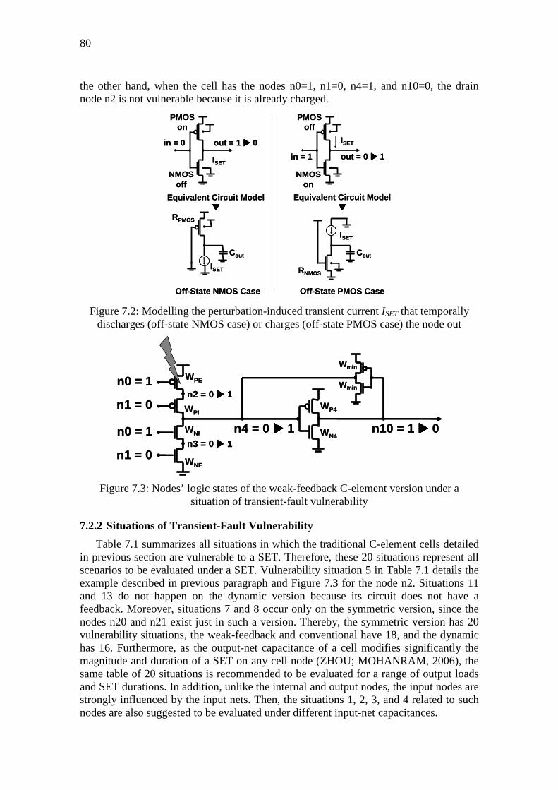
80
the other hand, when the cell has the nodes n0=1, n1=0, n4=1, and n10=0, the drain node n2 is not vulnerable because it is already charged.
Figure 7.2: Modelling the perturbation-induced transient current ISET that temporally discharges (off-state NMOS case) or charges (off-state PMOS case) the node out
Figure 7.3: Nodes’ logic states of the weak-feedback C-element version under a situation of transient-fault vulnerability
7.2.2 Situations of Transient-Fault Vulnerability
Table 7.1 summarizes all situations in which the traditional C-element cells detailed in previous section are vulnerable to a SET. Therefore, these 20 situations represent all scenarios to be evaluated under a SET. Vulnerability situation 5 in Table 7.1 details the example described in previous paragraph and Figure 7.3 for the node n2. Situations 11 and 13 do not happen on the dynamic version because its circuit does not have a feedback. Moreover, situations 7 and 8 occur only on the symmetric version, since the nodes n20 and n21 exist just in such a version. Thereby, the symmetric version has 20 vulnerability situations, the weak-feedback and conventional have 18, and the dynamic has 16. Furthermore, as the output-net capacitance of a cell modifies significantly the magnitude and duration of a SET on any cell node (ZHOU; MOHANRAM, 2006), the same table of 20 situations is recommended to be evaluated for a range of output loads and SET durations. In addition, unlike the internal and output nodes, the input nodes are strongly influenced by the input nets. Then, the situations 1, 2, 3, and 4 related to such nodes are also suggested to be evaluated under different input-net capacitances.
n4 = 0 ���� 1
WP4
WN4
Wmin
Wminn0 = 1
n1 = 0
WPE
WPI
WNI
WNE
n2 = 0 ���� 1
n3 = 0 ���� 1n0 = 1
n1 = 0
n10 = 1 ���� 0n4 = 0 ���� 1
WP4
WN4
Wmin
Wminn0 = 1
n1 = 0
WPE
WPI
WNI
WNE
n2 = 0 ���� 1
n3 = 0 ���� 1n0 = 1
n1 = 0
n10 = 1 ���� 0
in = 0 out = 1 ���� 0
PMOS on
NMOS off
ISETin = 1 out = 0 ���� 1
PMOS off
NMOS on
ISET
Equivalent Circuit Model����
ISET
ISET
Off-State NMOS Case Off-State PMOS Case
Cout
RPMOS
RNMOS
Cout
Equivalent Circuit Model����
in = 0 out = 1 ���� 0
PMOS on
NMOS off
ISETin = 1 out = 0 ���� 1
PMOS off
NMOS on
ISET
Equivalent Circuit Model����
ISET
ISET
Off-State NMOS Case Off-State PMOS Case
Cout
RPMOS
RNMOS
Cout
Equivalent Circuit Model����
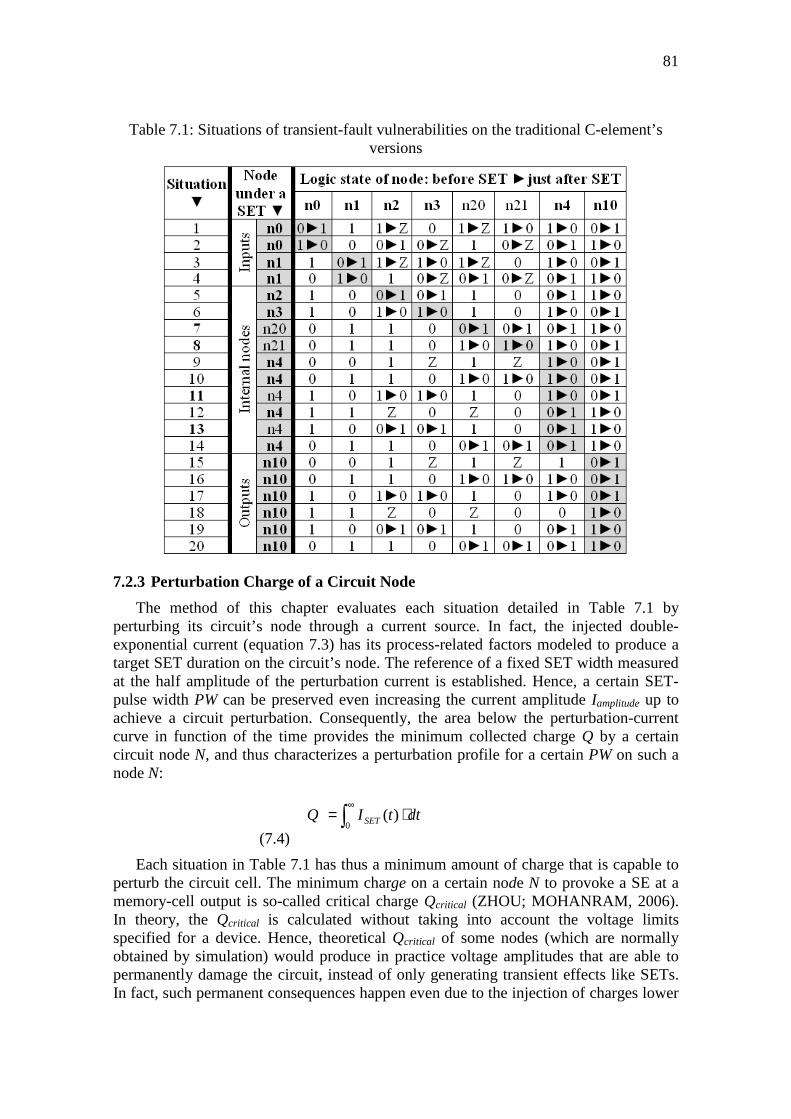
81
Table 7.1: Situations of transient-fault vulnerabilities on the traditional C-element’s versions
7.2.3 Perturbation Charge of a Circuit Node
The method of this chapter evaluates each situation detailed in Table 7.1 by perturbing its circuit’s node through a current source. In fact, the injected double-exponential current (equation 7.3) has its process-related factors modeled to produce a target SET duration on the circuit’s node. The reference of a fixed SET width measured at the half amplitude of the perturbation current is established. Hence, a certain SET-pulse width PW can be preserved even increasing the current amplitude Iamplitude up to achieve a circuit perturbation. Consequently, the area below the perturbation-current curve in function of the time provides the minimum collected charge Q by a certain circuit node N, and thus characterizes a perturbation profile for a certain PW on such a node N:
dttIQ SET ⋅= ∫∞
0)( �� �
(7.4)�
Each situation in Table 7.1 has thus a minimum amount of charge that is capable to perturb the circuit cell. The minimum charge on a certain node N to provoke a SE at a memory-cell output is so-called critical charge Qcritical (ZHOU; MOHANRAM, 2006). In theory, the Qcritical is calculated without taking into account the voltage limits specified for a device. Hence, theoretical Qcritical of some nodes (which are normally obtained by simulation) would produce in practice voltage amplitudes that are able to permanently damage the circuit, instead of only generating transient effects like SETs. In fact, such permanent consequences happen even due to the injection of charges lower

82
than the Qcritical, since certain target nodes have capacitances that are considered large in comparison with other circuit’s nodes.
Therefore, a node N of large capacitance can have its Qcritical higher than the minimum charge Qspecifications injected by a double-exponential current source to produce on N a voltage amplitude VN that is considered above the device specifications. Hence, the method of this chapter introduces the definition of perturbation charge PC on a circuit node N. It allows based on an injected charge evaluating only the non-permanent effects of the double-exponential current source. The PC for a certain PW is calculated by increasing Iamplitude up to meet either Qspecifications or Qcritical. It takes into account VN > 1.10·Vdd. Therefore, the PC is equal either to Qspecifications or Qcritical.
As each C-element cell has several vulnerability situations in accordance with Table 7.1, it has also several PCs. Then, a metric combining such PCs of a cell is mandatory to compare the SET robustness of different cells. The method of this chapter proposes such a metric based on the following points:
• Vulnerability situations with the lowest PCs require obviously lower minimum charges to perturb the circuit;
• In theory, there are much more perturbation events that can induce low charges on the circuits, since such a kind of event can be generated even from weak perturbation sources;
Therefore, as lower as higher perturbation-induced charges can upset the circuit in vulnerability situations with the lowest PCs, and so the systems are exposed to a higher amount of perturbation events. In this way, the lowest PCs have thus the widest ranges of sensitivity to perturbation events, and then they have evidently the biggest chances of provoking an error in the circuit. They are indeed the most transient-fault sensitive situations.
Such PCs of the highest error probabilities must have the highest impacts on the metric in order to valorize and evaluate the worst scenarios in terms of SET faults that a cell can be exposed. Hence, a solution as metric to combine the several PCs of a cell is using a mean that valorizes such lowest PCs. In theory, a weighted harmonic mean tends strongly toward its lowest elements, and so the lowest PCs would have the highest impacts on the mean. Therefore, the method of this chapter defines a global perturbation charge GPCV as the weighted harmonic mean of the several PCs of a cell version V.
7.3 Making Transient-Fault Robust the C-element There are many protection mechanisms in terms of transient-fault robustness which
are able to make robust a C-element circuit. The C-element is supposed to be used like a cell of a library in order to obtain optimal circuit designs (MAURINE et al, 2003; FOLCO et al, 2005). Then, the following paragraphs discuss transient-fault robust implementations of C-element cells by using transistor-abstraction level mitigation techniques. The target protection approaches work to increase the robustness of the cells in the worst scenarios without including new vulnerability situations.
A mitigation technique proposed in (KARNIK et al, 2002) is suggested in (VAIDYANATHAN et al, 2006) to make robust the C-element. Capacitors are explicitly added at the weakest circuit nodes in terms of perturbation charge by using PMOS and NMOS transistors as Figure 7.4 shows for the node n4.
83
Figure 7.4: The explicit-capacitor version of a weak-feedback C-element
Additionally, this section proposes a parameter labeled X to increase the transistor diffusion widths WNC and WPC in accordance with the second row of Table 7.2 (factors fPMOS and fload as well Wmin are defined in previous section 7.1). By amplifying X, the diffusion area becomes larger, and so the node’s capacitance also increases. Thus, a higher charge would be required to perturb the circuit. In addition, the node capability to attenuate a SET would be also improved. Then, the parameter X, which must be always greater than 1, would work to amplify the cell’s transient-fault robustness. The fourth row of Table 7.2 details the other diffusion widths of this approach in Figure 7.4 as well the diffusion widths of the traditional versions in Figure 7.1.
Table 7.2: Diffusion widths WN4, WP4, WNI, WPI, WNE, WPE WNC, and WPC of the NMOS and PMOS transistors in robust C-element cells
n4 n10
WP4
WN4
Wmin
Wminn0
n1
WPE
WPI
WNI
WNEn1
n0 WNC
WPC
n3
n2
n4 n10
WP4
WN4
Wmin
Wminn0
n1
WPE
WPI
WNI
WNEn1
n0 WNC
WPC
n3
n2

84
Similarly, there are the mitigation techniques based on symmetric or asymmetric sizing discussed in (ZHOU; MOHANRAM, 2006; LAZZARI et al, 2007) for combinational cells. The idea is increasing the transistor sizes and thus inserting additional capacitance on the circuit nodes. No extra transistors or nodes are included. Thereby, this section proposes other robust C-element implementations by only sizing their transistors in accord to Table 7.2. The circuits are the same detailed in Figure 7.1 but the diffusion widths WPE, WPI, WNI, and WNE are defined by Table 7.2. In fact, only the widths on the grey boxes in Table 7.2 are increased by WNC or WPC, which work also by the parameter X described in previous paragraph.
Other robust approaches can also be studied by implementing more sophisticated keepers. Sizing its transistors or adapting robust latches like those in (FAZELI et al, 2007; SASAKI; NAMBA; ITO, 2008; LAZZARI; ANGHEL; REIS, 2005; OMAÑA; ROSSI; METRA, 2007) can amplify the transient-fault robustness of the C-element cells. However, such special latches include extra transistors on the data path. Therefore, they naturally would increase the delay, area, and power consumption of the cell. Moreover, they also would implement additional circuit nodes vulnerable to transient faults. Other protection schemes in (MOHAMMADI; FURBER; GARSIDE, 2003; KUMA; TAHOORI, 2005; UEMURA et al, 2008) based on transistor insertions can also improve the cell robustness but they also will include new vulnerability situations.
7.4 Evaluations of the C-element’s Implementations The traditional C-element cells illustrated in previous sections and their robust
versions defined in Table 7.2 were evaluated by using the methodology of this chapter.
7.4.1 Simulation Experiments
The evaluation methodology requires fault-injection campaigns at transistor-abstraction level. Then, HSPICE-based simulations were performed.
All C-element versions were created based on previous sections 7.1 and 7.3, and Table 7.2 in order to design and evaluate them under similar conditions. The circuit versions were designed by using a 65-nm CMOS technology, Vdd 1.2V, and typical parameters. All of them were made to have the cell-drive capability X04, which is the lowest one of similar cells (like AND or OR gates) in the target CMOS technology library. Hence, the lowest capacitances possible to be implemented, which represent the most transient-fault sensitive condition, were evaluated.
Moreover, all cells were sized to meet an output of rise and fall times in the order of 300ps, which is a reasonable and quite similar reference to the typical cells of the target CMOS technology library. It was done by using the largest standard load of X04 (72.8fF) and the shortest input-net transition from the target technology library (5ps). In this way, factors fPMOS and fload, discussed in section 7.1, were obtained for each one of the cell versions.
The many simulations of fault injections on the cell nodes were done in accord to Table 7.1. Each situation of this Table 7.1 was simulated for typical SET widths of 50ps, 100ps, and 250ps (DODD, 2004; FERLET-CAVROIS, 2006) by using the minimum and maximum standard loads of X04. In addition, two of the lowest input-net

85
capacitances, which correspond to the worst scenarios in terms of perturbation charges on the input nodes, were also evaluated for situations 1, 2, 3, and 4 of Table 7.1.
7.4.2 Simulation Results and Evaluations
The simulation results of the designed C-element versions are illustrated in the figures of this section. In fact, the figures show the percent increases of each version in relation to the results of the dynamic version detailed in Figure 7.1 (A), since it presents the least values. The black triangle (▲) in figures represents the weak-feedback version, the black circle (●) is the conventional version, and the black square (■) is the symmetric version. The figures’ curves are plotted by increasing the parameter X, which is defined in previous section as the factor to amplify the circuit robustness.
Figure 7.5 shows the percent increases in global perturbation charge GPCV, which is defined in previous section, in function of the percent penalties in delay of the designed C-element versions. The delay was calculated by the arithmetic mean of the rise delay and the fall delay.
Firstly, taking into account only the C-element versions without transient-fault mitigation techniques, the results in Figure 7.5 show that the symmetric version (black square, ■) is 0.52% slower than dynamic version. The conventional (black circle, ●) is 3.33% and the weak-feedback (black triangle, ▲) is 14.24%. The resistance of the feedback in the keeper works to penalty the delay when the input drivers are to switch the output state. Furthermore, the GPCV results in Figure 7.5 prove that the weak-feedback C-element is the strongest version in terms of transient-fault robustness. In fact, the weak-feedback is 144.04% more robust than the dynamic version, i.e., the minimum charges to perturb its nodes need be on average 144.04% larger than those to perturb the dynamic version. On the other hand, the conventional and symmetric versions are respectively 91.18% and 59.04% more robust. The weak-feedback version has the highest GPCV basically because its internal node n2, n3, and n4 are designed more capacitive to overcome the feedback resistance in the situations of output changes. In addition, the symmetric version has more circuit nodes that are available to be perturbed.
The curves in Figure 7.5 represent robust C-element versions. In fact, the figure shows the versions protected by the techniques from Table 7.2. However, only those versions that present the worst and the best trend in GPCV increases as functions of the delay penalties were plotted. For instance, the weak_feedback_explicit_capacitor_Xw curve beginning at the black triangle (▲) performs the worst trend among those robustness techniques in Table 7.2 applied on the weak_feedback version. It means that such an explicit_capacitor_Xw approach is the technique that further penalizes the weak-feedback cell’s delay, since the goal is always achieving higher GPCV increases by using lower delay penalties. On the other hand, the weak_feedback_sizing_external_ Xw curve is the best trend. If the goal is to increase the SET robustness of the weak_feedback version around 165% larger than that of the dynamic version, the sizing_external_Xw technique will introduce a penalty of 3% in delay in relation to the fastest C-element version (dynamic). Otherwise, the explicit_capacitor_Xw will increase by about 21% the delay.
The trends of the other mitigation techniques detailed in Table 7.2 also begin from the black triangle (▲), circle (●), or square (■). However, they are placed in the range between the best and the worst trend curves. These curves were also got by simulation

86
but they are not shown in the figures. Such an illustration in terms of the best and worst trends of mitigation techniques were also done in the following figures of this section.
Figure 7.5: GPCV increases vs. penalties in delay of C-element versions
The results in GPCV increases as functions of delay penalties also illustrates that the techniques of resizing_Xw, sizing_external_Xw, sizing_external_pmos_Xw, and sizing_ external_nmos_Xw reduce the C-element’s delay in function of increasing the parameter X to amplify the cell robustness. These techniques have in common to enlarge the transistors connected to gnd or Vdd. It indicates that more current flows with less resistance from its source or drain, thus the circuits are faster. The best trend among all versions is the symmetric_sizing_external_Xw curve, thus it is ideal for designs targeting high performances. Otherwise, for all other versions, the penalties in delay tend to rise as greater as the parameter X amplifies. It is basically because the capacitance on the internal node n4 increases by using such techniques, then the process to charge it will be slower. The explicit_capacitor_Xw technique is the worst in terms of delay for the reason that it includes explicit extra capacitance on the current’s path.
Figure 7.6 shows the GPCV increases as functions of the power-consumption overheads of the C-element versions. The symmetric and conventional versions have lower power consumption than the weak-feedback version (respectively 2.03%, 2.67%, and 12.18%, as shown in Figure 7.6) because they cut off their keeper feedbacks to switch their output states. The explicit_capacitor_Xw technique is the most power
55
65
75
85
95
105
115
125
135
145
155
165
175
185
195
205
-3 0 3 6 9 12 15 18 21∆% Delay
∆% Global Perturbation Charge
weak_feedback_sizing_external_Xw
weak_feedback_explicit_capacitor_Xw
conventional_sizing_external_Xw
conventional_sizing_internal_pmos_Xw
symmetric_sizing_external_Xw
symmetric_explicit_capacitor_Xw
▲weak_feedback
● conventional
■ symmetric

87
efficient because each one of its transistors does not become as so larger as in the other techniques. In addition, the conventional_explicit_capacitor_Xw versions have the best trend curve among all versions basically due to the least efforts in the output switches. It is recommended for designs that require low power. On the other hand, the sizing_external_nmos_Xw and sizing_external_nmos_Xw approach are the most power inefficient.
Figure 7.6: GPCV increases vs. power-consumption overheads
Figure 7.7 illustrates the GPCV increases as functions of the diffusion-area overheads of the C-element versions. The diffusion area works like an estimate of the total cell layout area. The diffusion area of the symmetric version is 5.55% greater than the dynamic version, the conventional is 15.04% and the weak-feedback is 10.75% larger. The sizing_internal_Xw technique is the best trend when the goal is low area. Otherwise, the sizing_external_nmos_Xw and sizing_external_pmos_Xw protections are not interesting for low-area cells.
55
65
75
85
95
105
115
125
135
145
155
165
175
185
195
205
215
225
235
0 3 6 9 12 15 18 21
∆% Power Consumption
∆% Global Perturbation Charge
weak_feedback_explicit_capacitor_Xw
weak_feedback_sizing_external_nmos_Xw
conventional_explicit_capacitor_Xw
conventional_sizing_external_nmos_Xw
symmetric_explicit_capacitor_Xw
symmetric_sizing_external_nmos_Xw
▲weak_feedback
● conventional
■ symmetric

88
Figure 7.7: GPCV increases vs. diffusion-area overheads
Figure 7.8 shows what C-element versions present higher perturbation charges by using lower implementation costs. Taking into account that implementation cost is the arithmetic mean of the overheads in terms of delay, power consumption, and diffusion area plotted in Figure 7.5, Figure 7.6, and Figure 7.7. Figure 7.8 proves even more that the weak-feedback version is the best robust option because it has an implementation cost of around 12% larger than the dynamic version but is around 2.5 times more SET robust. The other traditional versions would require a huge additional redundancy in terms of implementations costs to achieve the same SET immunity level.
The curves of the weak-feedback versions in Figure 7.8 are higher in terms of GPCV increases at least up to implementation costs of around 40% (point beyond the curve shown in Figure 7.8), therefore such versions are more SET robust than the other ones at least up to this point. In fact, such an intersection point at around 40% is only due to the worst trend in GPCV increases for the weak_feedback version (weak_feedback _sizing_external_nmos_Xw curve) with the best trend for the conventional version (conventional_sizing_internal_nmos_Xw curve). The best trend for the weak_feedback version (weak_feedback_sizing_internal_Xw curve) is not reached for the other mitigation techniques because it has the highest rise rate. Therefore, such a weak_feedback_sizing_internal_Xw technique is the best option to make more robust
55
65
75
85
95
105
115
125
135
145
155
165
175
185
195
205
0 5 10 15 20 25 30 35 40 45 50 55 60 65
∆% Diffusion Area
∆% Global Perturbation Charge
weak_feedback_sizing_internal_Xw
weak_feedback_sizing_external_nmos_Xw
conventional_sizing_internal_Xw
conventional_sizing_external_nmos_Xw
symmetric_sizing_internal_Xw
symmetric_sizing_external_pmos_Xw
▲weak_feedback
● conventional
■ symmetric
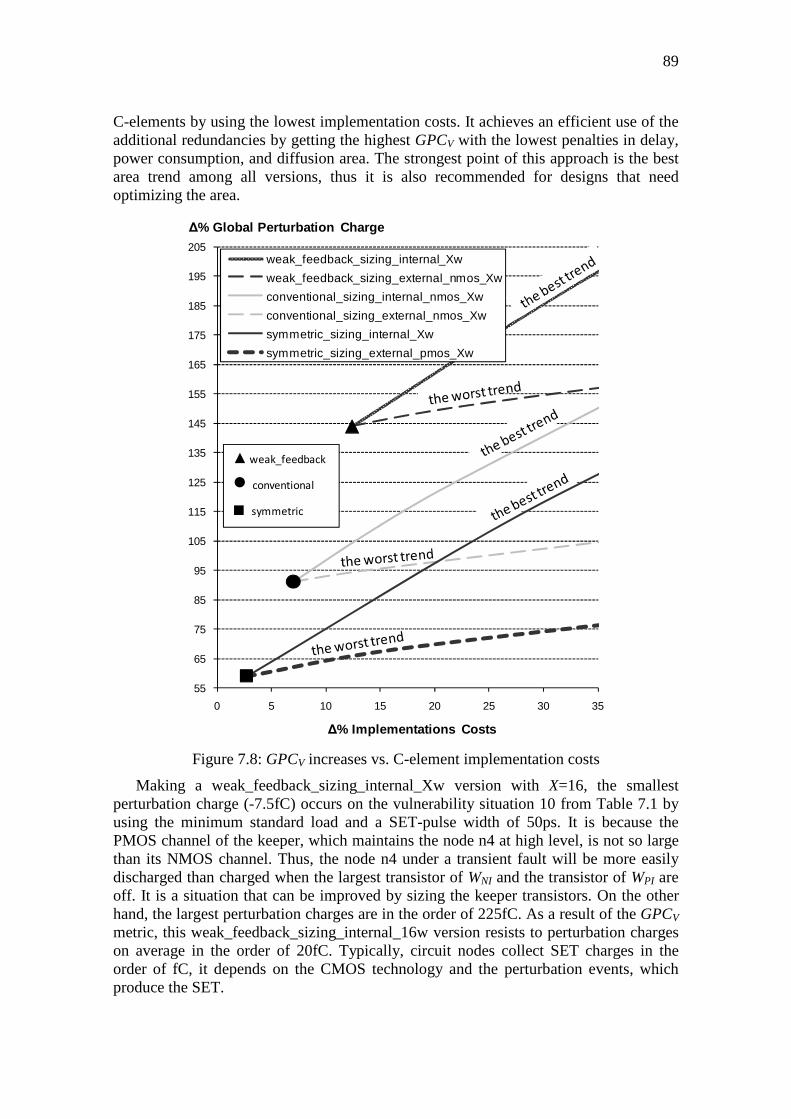
89
C-elements by using the lowest implementation costs. It achieves an efficient use of the additional redundancies by getting the highest GPCV with the lowest penalties in delay, power consumption, and diffusion area. The strongest point of this approach is the best area trend among all versions, thus it is also recommended for designs that need optimizing the area.
Figure 7.8: GPCV increases vs. C-element implementation costs
Making a weak_feedback_sizing_internal_Xw version with X=16, the smallest perturbation charge (-7.5fC) occurs on the vulnerability situation 10 from Table 7.1 by using the minimum standard load and a SET-pulse width of 50ps. It is because the PMOS channel of the keeper, which maintains the node n4 at high level, is not so large than its NMOS channel. Thus, the node n4 under a transient fault will be more easily discharged than charged when the largest transistor of WNI and the transistor of WPI are off. It is a situation that can be improved by sizing the keeper transistors. On the other hand, the largest perturbation charges are in the order of 225fC. As a result of the GPCV metric, this weak_feedback_sizing_internal_16w version resists to perturbation charges on average in the order of 20fC. Typically, circuit nodes collect SET charges in the order of fC, it depends on the CMOS technology and the perturbation events, which produce the SET.
55
65
75
85
95
105
115
125
135
145
155
165
175
185
195
205
0 5 10 15 20 25 30 35
∆% Implementations Costs
∆% Global Perturbation Charge
weak_feedback_sizing_internal_Xw
weak_feedback_sizing_external_nmos_Xw
conventional_sizing_internal_nmos_Xw
conventional_sizing_external_nmos_Xw
symmetric_sizing_internal_Xw
symmetric_sizing_external_pmos_Xw
▲weak_feedback
● conventional
■ symmetric

90
7.5 Conclusions A methodology able to evaluate SET effects on C-element implementations is
proposed in this work. A table with all SET vulnerability situations on traditional C-element circuits is presented.
The results prove that the weak-feedback version is the most transient-fault robust one among the traditional C-element options mainly because its design needs to face the feedback resistance during output switches.
Options of robust C-element versions were studied by means of the concept of perturbation charge, and the weak-feedback implementations based on symmetric sizing of internal PMOS and NMOS transistors (sizing_internal_Xw) resulted as the best approach against the SET problem. Thus, designers or even automatic synthesis tools are able to get systems even more robust by taking the best C-element versions in terms of SET robustness.
8 CONCLUSIONS AND FUTURE WORKS
Deep-submicron IC technologies have quite contributed to scientific development in many ways. However, the huge IC reliability-related problems, mostly in synchronous circuits, have pushed researchers into breaking old paradigms. Hence, this thesis aimed at exploiting QDI asynchronous circuits in order to take advantage of their clockless issues, and thus obtaining more robust systems.
Many QDI asynchronous circuits’ characteristics seem to be more interesting than the synchronous circuits’ ones when the target is designing robust systems. This thesis discussed comparatively the transient-fault effects on both these classes of circuits, and pointed out benefits of such an important QDI asynchronous design’s alternative. In addition, simple design techniques that make a QDI system even more transient-fault robust are suggested. Then, the main thesis’s contributions are thus summarized below:
• A novel method for logical-level evaluation of transient-fault effects as on synchronous as QDI asynchronous circuits (chapter 4; BASTOS et al, ETS 2009-a; BASTOS et al, IOLTS 2009-b);
• Highlighting for the first time in (chapter 5; BASTOS et al, ETS 2010-a; BASTOS et al, ESREF & Microelectronics Reliability Journal 2010-c) the excellent natural QDI asynchronous systems’ ability for mitigation of LDT faults in deep-submicron technologies;
• Showing experimentally that the costs to protect complex synchronous systems at different abstraction levels vary in terms of the system’s overheads and development’s expenses, and that they can be very high depending on the number of system’s memory elements (chapter 6; BASTOS et al, Microelectronics Journal 2009-c);
• A novel method for electrical-level evaluation of transient-fault effects on C-element’s cells as well as presenting for the first time the best traditional C-element’s versions to design more transient-fault robust QDI asynchronous systems (chapter 7; BASTOS et al, IOLTS 2010-b).
The novel method for logical-level transient-fault effect evaluation allows comparing the sensitivity of circuits that are functionally equal but architecturally different. Then, unlike related works, it takes into account the QDI asynchronous systems’ particularities as well as the synchronous systems’ ones. Such a kind of logical-level simulation-based method simplifies the transient-fault effects because the real transient-fault features are not able to be characterized at such an abstraction level. Therefore, certain evaluation’s accuracy is replaced by a more feasible simulation complexity. Nevertheless, a very-meaningful preliminary assessment of such transient-

92
fault effects on the system’s designs can be done without the expenses of real-circuit level testing platforms.
Beyond such a novel method, this thesis classifies two types of failures: detectable naturally (FDN) and non-detectable naturally (FNN). It highlights innovatively the natural QDI asynchronous systems’ ability to mitigate long-duration transient (LDT) faults in deep-submicron technologies. In fact, as a long transient stays longer time in data path, it has a higher probability to become a failure, and as most of the failure cases in QDI systems are FDN due to the QDI asynchronous properties, such a kind of transient fault is always more probable to become a FDN when is not tolerated naturally. On the contrary, the clock’s period of synchronous systems imposes bounded delays, then LDT faults very likely result in FNN.
These FDN-related issues were shown experimentally in a case study on a DES crypto-processor in synchronous and QDI asynchronous versions. In addition, as the largest part of FNN cases in QDI systems are arisen from forbidden codification states. They are easily detectable by low-cost alarm mechanisms (MOORE et al, 2003), and then a QDI system can achieve transient-fault immunity levels very close to 100 %. On the other hand, a synchronous system would require modifying its architecture by including expensive mitigation techniques as well as it would have higher development costs in terms of additional designers, time-to-market, and fabrication. In fact, fully protecting complex synchronous systems against transient faults rarely would cost less than a circuit’s area duplication. Rare cases, as illustrated in Figure 6.10, would be systems with a low amount of memory elements, even so they would not be protected against LDT faults, delay faults, and DPA attacks.
On the contrary, one could argue that the case-study’s results showed the synchronous DES’s version (des_sync) less sensitive to transient-fault effects than the QDI asynchronous DES’s version (des_async). However, the results also showed a high des_async’s potential to have lower transient-fault sensitivity than the des_sync. Indeed, as no alarm mechanisms were embedded in such a des_async, it takes no advantage of the forbidden codification cases. Then, if the alarms are installed, des_async’s sensitivity certainly would close a lot to 0, and so would be lesser than the des_sync’s sensitivity. Furthermore, the results also illustrated that the area and computation-time factors were decisive to reach a sensitivity-related conclusion. Actually, the area and computation time in such a case-study des_async are not the most optimized ones. This des_async was designed before the new asynchronous-dedicated synthesis methods (FOLCO et al, 2005; TIEMPO, 2009), and thus its natural higher transient-fault resistance is suppressed due to its larger area and computation-time factors.
Nevertheless, modern QDI asynchronous systems, based on such novel synthesis methods, can be designed by using less than twice larger area than their synchronous counterparts as well as taking at least a comparable computation time. These QDI systems’ improvements are mostly in terms of logic synthesis, and then their data codification and asynchronous handshaking communication are not violated. Therefore, their natural ability in transient-fault situations to often produce FDN instead of FNN remains even by using these modern synthesis methods, and so their higher transient-fault resistance prevails over the area and computation-time factors. Hence, the des_async’s transient-fault sensitivity would be yet more reduced down the des_sync’s sensitivity, i.e., the des_async would be more transient-fault robust than the des_sync.

93
This thesis still proposed a novel method for electrical-level transient-fault effect evaluation that allows comparing the robustness of different C-element’s cells. Unlike related works, it is able to evaluate cells’ circuits regardless of clock-related issues. As a consequence, the transient-fault robustness of QDI asynchronous systems can be considerably improved because from now on the designers or EDA tools know the best C-element’s versions for such a design application target.
All these modern QDI asynchronous circuits’ improvements, discussed in last paragraphs, linked with their natural properties in terms of QDI, low EMI, high DPA security, high modularity, and low power consumption make them very attractive to design robust systems.
As future works, an investigation could be done into other types of C-elements beyond those ones evaluated in this thesis as well as exploiting the perturbation charges on C-element’s implementations based on lower Vdd and smaller CMOS technologies, which represent even worse scenarios for transient-fault effects. Furthermore, the strong natural QDI asynchronous systems’ ability to mitigate LDT faults could be proved formally by improving the symbolic simulation proposed in (MONNET; RENAUDIN; LEVEUGLE, 2007-b) with the LDT characteristics. Another future work would be integrating in EDA tools the knowledge of what C-element cells are the most transient-fault robust.
Finally, an ongoing work will show a meaningful improvement of the C-element cells’ transient-fault robustness. Actually, preliminary evaluations illustrate that the C-element’s design based on a combination of folding and sizing increase even more the cell robustness.

94

AUTHOR’S REFERENCES
• International Journals:
BASTOS, R. P.; KASTENSMIDT, F.; REIS, R. Design of a Soft-Error Robust Microprocessor. Elsevier Microelectronics Journal, doi:10.1016/j.mejo.2008.10.001 (Nov. 2008), v.40, n.7, p. 1062-1068, Jul. 2009-c.
BASTOS, R. P.; SICARD, G.; KASTENSMIDT, F. L.; RENAUDIN, M.; REIS, R. Asynchronous Circuits as Alternative for Mitigation of Long-Duration Transient Faults in Deep-Submicron Technologies. In: EUROPEAN SYMPOSIUM ON REABILITY OF ELECTRON DEVICES, FAILURE PHYSICS and ANALYSIS, ESREF, 21., 2010, Monte Cassino Abbey and Gaeta, Italy. Elsevier Microelectronics Reliability Journal, 2010-c.
• International Conferences with Review Committee:
BASTOS, R. P.; SICARD, G.; KASTENSMIDT, F.; RENAUDIN, M.; REIS, R. Evaluating Transient-Fault Effects on Traditional C-element‘s Implementations. In: INTERNATIONAL ON-LINE TESTING SYMPOSIUM, IOLTS, 16., 2010, Corfu Island, Greece. Proceedings... Los Alamitos, CA, USA : IEEE Computer Society, 2010-b.
BASTOS, R. P.; SICARD, G.; KASTENSMIDT, F. L.; RENAUDIN, M.; REIS, R. Asynchronous Circuits as Alternative for Mitigation of Long-Duration Transient Faults in Deep-Submicron Technologies. In: EUROPEAN TEST SYMPOSIUM, ETS, 15., 2010, Prague, Czech Republic. Digest of Papers... [S.l.]: IEEE Computer Society, 2010-a.
BASTOS, R. P.; MONNET, Y.; SICARD, G.; KASTENSMIDT, F.; RENAUDIN, M.; REIS, R. Comparing Transient-Fault Effects on Asynchronous and on Synchronous Circuits. In: INTERNATIONAL ON-LINE TESTING SYMPOSIUM, IOLTS, 15., 2009, Sesimbra-Lisbon, Portugal. Proceedings... Los Alamitos, CA, USA : IEEE Computer Society, 2009-b.
BASTOS, R. P.; MONNET, Y.; SICARD, G.; KASTENSMIDT, F. L.; RENAUDIN, M.; REIS, R. A Methodology to Evaluate Transient-Fault Effects on Asynchronous and Synchronous Circuits. In: EUROPEAN TEST SYMPOSIUM, ETS, 14., 2009, Seville, Spain. Digest of Papers... [S.l.] : IEEE Computer Society, 2009-a.
BASTOS, R. P.; KASTENSMIDT, F. L.; REIS, R. Design at High Level of a Robust 8-Bit Microprocessor to Soft Errors by Using Only Standard Gates. In: SYMPOSIUM ON

96
INTEGRATED CIRCUITS AND SYSTEMS DESIGN, SBCCI, 19., August 28 – September 1, 2006, Ouro Preto, Brazil. Proceedings... [S.l.]: ACM, 2006-d. p. 196-201.
BASTOS, R. P.; KASTENSMIDT, F. L.; REIS, R. Design of a Robust 8-Bit Microprocessor to Soft Errors. In: INTERNATIONAL ON-LINE TESTING SYMPOSIUM, IOLTS, 12., July 10-12, 2006, Lake of Como, Italy. Proceedings... [S.l.]: IEEE Computer Society, 2006-c. p. 195-196.
BASTOS, R. P.; KASTENSMIDT, F. L.; REIS, R. Design of a Robust 8-Bit Microprocessor to Soft Single Event Effects. In: LATIN AMERICAN TEST WORKSHOP, LATW, 7., March 26-29, 2006, Buenos Aires, Argentina. Digest of Papers... [S.l.]: IEEE Computer Society, 2006-a. p. 137-142.
BASTOS, R. P.; KASTENSMIDT, F. L.; REIS, R. Designing Low Power Embedded Software for Mass-Produced Microprocessor by Using a Loop Table in On-Chip Memory. In: INTERNATIONAL WORKSHOP ON POWER AND TIMING MODELING, OPTIMIZATION AND SIMULATION, PATMOS, 15., September 20-23, 2005, Leuven, Belgium. Proceedings… Berlin, Germany: Springer, 2005-b. p. 59-68. (Lecture Notes in Computer Science, LNCS, v. 3728).
• Works evaluated by an examining board:
BASTOS, R. P. Circuitos Assíncronos QDI: Uma Alternativa Naturalmente Robusta a Desafios das Tecnologias Submicrônicas. 2009-d. 98 f. Thesis Proposal (Ph.D) – PGMicro, Instituto de Informática, UFRGS, Porto Alegre.
BASTOS, R. P. Design of a Soft-Error Robust Microprocessor. 2006-e. 120 f. Thesis (Master) – PPGC, Instituto de Informática, UFRGS, Porto Alegre.
• Regional Symposium with Review Committee:
BASTOS, R. P.; KASTENSMIDT, F. L.; REIS, R. Design of a Robust 8-Bit Microprocessor to Soft Single Event Effects. In: SOUTH SYMPOSIUM ON MICROELECTRONICS, SIM, 21., May 8, 2006, Porto Alegre, RS, Brazil. Proceedings… Porto Alegre, RS, Brazil: Universidade de Federal do Rio Grande do Sul, UFRGS, 2006-b. p. 151-155.
BASTOS, R. P.; KASTENSMIDT, F. L.; REIS, R. Designing Low Power Embedded Software for Mass-Produced Microprocessor by Using a Loop Table in On-Chip Memory. In: SOUTH SYMPOSIUM ON MICROELECTRONICS, SIM, 20., May 6-7, 2005, Santa Cruz do Sul, RS, Brazil. Proceedings… Porto Alegre, RS, Brazil: Universidade de Santa Cruz do Sul, UNISC, 2005-a. p. 137-140.
• Regional Symposium:
CENTENO, P. C. ; BASTOS, R. P. ; REIS, R. . Simulação de Circuitos Assíncronos QDI no Nível de Transistores sob o Efeito de Injeção de Falhas. In: SALÃO DE INICIAÇÃO CIENTÍFICA, SIC, 18., 2007, Porto Alegre, RS. Livro de Resumos.... Porto Alegre, RS : Universidade Federal do Rio Grande do Sul, UFRGS: Resumo, 2007.
MANITO, R. ; BASTOS, R. P. ; REIS, R. . Simulação de Circuitos Robustos através de Injeção de Falhas no Nível de Portas Lógicas.. In: SALÃO DE INICIAÇÃO

97
CIENTÍFICA, SIC, 17, 2006, Porto Alegre, RS. Livro de Resumos.... Porto Alegre, RS : Universidade Federal do Rio Grande do Sul, UFRGS: Resumo, 2006.
BASTOS, R. P. ; PIAZZA, A. ; PALUDO, L. H. ; LOUREIRO, L. T. R. . Acionamento Microcontrolado de Motor de Passo Através de Sinais Infravermelho Padrão RC5. In: SALÃO DE INICIAÇÃO CIENTÍFICA, SIC, 13., 2001, Porto Alegre, RS. Livro de Resumos.... Porto Alegre, RS : Universidade Federal do Rio Grande do Sul, UFRGS: Resumo 002, 2001. p. 649.
BASTOS, R. P. ; SUSIN, A. A. . Sistema Microprocessado de Medição de Vibração para Aquisição em Tempo Real. In: SALÃO DE INICIAÇÃO CIENTÍFICA, SIC, 13., 2001, Porto Alegre, RS. Livro de Resumos.... Porto Alegre, RS : Universidade Federal do Rio Grande do Sul, UFRGS: Resumo 191, 2001. p. 223.
BASTOS, R. P. ; NEGREIROS, M. ; SUSIN, A. A. ; PARDI JUNIOR, W. ; MARCAL, R. F. M. Sistema de Medição de Vibração com Acelerômetro de Estado Sólido.. In: SALÃO DE INICIAÇÃO CIENTÍFICA, SIC, 12., 2000, Porto Alegre, RS. Livro de Resumos.... Porto Alegre, RS : Universidade Federal do Rio Grande do Sul, UFRGS: Resumo 011, 2000. p. 539.

98

REFERENCES
ABRAMOVICI, M.; BREUER, M. A.; FRIEDMAN, A. D. Digital Systems Testing and Testable Design. New York: IEEE, 1990.
ALBRECHT, C. et al. Towards a Flexible Fault-Tolerant System-on-Chip. In: INTERNATIONAL CONFERENCE ON ARCHITECTURE OF COMPUTING SYSTEMS, 22., 2009, ARC 2009, Karlsruhe, GER. Proceedings… Berlin, GER: VDE Verlag GMBH, 2009, p. 83-90.
ALEXANDRESCU, D.; ANGHEL, L.; NICOLAIDIS, M. New Methods for Evaluating the Impact of Single Event Transients in VDSM ICs. In: IEEE INTERNATIONAL SYMPOSIUM ON DEFECT AND FAULT TOLERANCE IN VLSI SYSTEMS, DFT, 17., 2002. Proceedings… [S.l.]: IEEE Computer Society, 2002. p. 99-107.
ALEXANDRESCU, D.; ANGHEL, L.; NICOLAIDIS, M. Simulating Single Event Transients in VDSM ICs for Ground Level Radiation. Journal of Electronic Testing: Theory and Applications, [S.l.]: Kluwer Academic Publishers, v. 20, n. 4, p. 413-421, 2004.
ANGHEL, L.; NICOLAIDIS, M. Cost Reduction and Evaluation of a Temporary Faults Detecting Technique. In: DESIGN, AUTOMATION AND TEST IN EUROPE CONFERENCE AND EXHIBITION, DATE, 2000, Paris. Proceedings… Los Alamitos: IEEE Computer Society, 2000-a. p. 591-598.
ANGHEL, L.; ALEXANDRESCU, D.; NICOLAIDIS, M. Evaluation of a Soft Error Tolerance Technique Based on Time and/or Space Redundancy. In: SYMPOSIUM ON INTEGRATED CIRCUITS AND SYSTEMS DESIGN, SBCCI, 13., 2000, Manaus. Proceedings… Los Alamitos: IEEE Computer Society, 2000-b. p. 237-242.
ALMUKHAIZIM, S.; MAKRIS, Y. Fault tolerant design of combinational and sequential logic based on a parity check code. In: INTERNATIONAL SYMPOSIUM ON DEFECT AND FAULT TOLERANCE IN VLSI SYSTEMS, 18., 2003, DFT 2003, Boston, USA. Proceedings... Los Alamitos, USA: IEEE Computer Society, 2003, p. 344-351.
ALMUKHAIZIM, S.; SHI, F.; MAKRIS, Y. Coping with Soft Errors in Asynchronous Burst-Mode Machines. In: INTERNATIONAL SYMPOSIUM ON ASYNCHRNOUS CIRCUITS AND SYSTEMS, ASYNC, 14., 2008. Proceedings… [S.l.]: IEEE, 2008, p. 151-160.

100
ARGYRIDES, C.; ZARANDI, H. R.; PRADHAN, D. K. Matrix codes: multiple bit upsets tolerant method for SRAM memories. In: IEEE INTERNATIONAL SYMPOSIUM ON DEFECT AND FAULT-TOLERANCE IN VLSI SYSTEMS, 22., 2007, DFT 2007, Rome, ITA. Proceedings… Washington, USA: IEEE Computer Society, 2007, p. 340-348.
ASSIS, T.; KASTENSMIDT, F. L.; WIRTH, G.; REIS, R. Measuring the effectiveness of symmetric and asymmetric transistor sizing for Single Event Transient mitigation in CMOS 90nm technologies. In: LATIN AMERICAN TEST WORKSHOP, LATW, 10., 2009. Proceedings... Los Alamitos: IEEE, 2009-a, p. 1-6.
ASSIS, T. Analysis of Transistor Sizing and Folding Effectiveness to Mitigate Soft Errors . 2009-b. Thesis (Master) – PPGC, Instituto de Informática, UFRGS, Porto Alegre.
BALSA. Asynchronous design and synthesis tool. England. Available at: <http://intranet.cs.man.ac.uk/apt/>. Visited on November 2009.
BARTH, J. Applying Computer Simulation Tools to Radiation Effects Problems. In: IEEE NUCLEAR SPACE RADIATION EFFECTS CONFERENCE, NSREC, 1997. Proceedings… [S.l.]: IEEE Computer Society, 1997. p. 1-83.
BAUMANN, R.; SMITH, E. Neutron-Induced Boron Fission as a Major Source of Soft Errors in Deep Submicron SRAM Devices. In: IEEE INTERNATIONAL ELIABILITY PHYSICS SYMPOSIUM, 38., 2000. Proceedings… [S.l.]: IEEE Computer Society, 2000.
BAUMANN, R. C. Soft Errors in Advanced Semiconductor Devices—Part I: The Three Radiation Sources. IEEE Transactions on Device and Materials Reliability, [S.l.], v. 1, n. 1, p. 17-22, Mar. 2001.
BORKAR, S. Designing Reliable Systems from Unreliable Components: The Challenges of Transistor Variability and Degradation. IEEE Micro , [S.l.], v.25, n.6, p. 10-16, Nov.-Dec. 2005.
BOUESSE, G. F. et al. Asynchronous AES Crypto-processor Including Secured and Optimized Blocks. Journal of Integrated Circuits and Systems, JICS, [S.l.:s.n], v.1, n.1, 2004.
BOUESSE, G. F. et al. DPA on quasi delay insensitive asynchronous circuits: formalization and improvement. In: DESIGN, AUTOMATION AND TEST IN EUROPE CONFERENCE AND EXHIBITION, DATE, 2005. Proceedings… Los Alamitos: IEEE Computer Society, 2005, p. 424-429.
BOUESSE, G. F. Contribution à la conception de circuits intégrés sécurisés : l’alternative asynchrone. 2005. 202 f. Thesis (Ph.D) – EEATS, TIMA, INPG, Grenoble, France.
BRZOZOWSKI, J. A.; SEGER, C. H. Asynchronous Circuits. New York: Springer-Verlag, 1995.

101
BREGIER, V. Synthèse automatisée de circuits asynchrones optimisés prouvés quasi insensibles aux délais. 2007. 116 f. Thesis (Ph.D) – EEATS, TIMA, INPG, Grenoble, France.
CALIN, T.; VARGAS, F.L.; NICOLAIDIS, M. Upset-Tolerant CMOS SRAM Using Current Monitoring: Prototype And Test Experiments. In: INTERNATIONAL TEST CONFERENCE, ITC, 1995. Proceedings... [S.l.]: IEEE, 1995. p. 45-53.
CALIN, T.; NICOLAIDIS, M.; VELAZCO, R. Upset Hardened Memory Design for Submicron CMOS Technology. IEEE Transactions on Nuclear Science, New York, v.43, n.6, p. 2874 -2878, Dec. 1996.
CAZEAUX, J. M.; ROSSI, D.; OMANA, M.; METRA, C.; CHATTERJEE, A. On Transistor Level Gate Sizing for Increased Robustness to Transient Faults. In: IEEE INTERNATIONAL ON-LINE TESTING SYMPOSIUM, IOLTS, 2005. Proceedings… Washington, USA: IEEE Computer Society, 2005, p. 23-28.
CHA, H.; PATEL, J. H. A Logic-Level Model for α-Particle Hits in CMOS Circuits. In: COMPUTER DESIGN: VLSI IN COMPUTERS AND PROCESSORS, ICCD, 2004. Proceedings... [S.l.]: IEEE, 1993. p. 538-542.
CHAPIRO, D. Globally-Asynchronous Locally-Synchronous Systems. 1984. Thesis (Ph.D.) - Stanford University, USA.
COCHRAN, D. J. et al. Recent Total Ionizing Dose Results and Displacement Damage Results for Candidate Spacecraft Electronics for NASA. In: RADIATION EFFECTS DATA WORKSHOP, 2005. Proceedings... [S.l.]: IEEE, 2005. p. 149-155.
CONSTANTINESCU, C. Neutron SER Characterization of Microprocessors. In: INTERNATIONAL CONFERENCE ON DEPENDABLE SYSTEMS AND NETWORKS, DSN, 2005. Proceedings... [S.l.]: IEEE Computer Society, 2005. p. 754-759.
COTA, E.; LIMA, F.; REZGUI, S.; CARRO, L.; VELAZCO, R.; LUBASZEWSKI, M.; REIS, R. Synthesis of an 8051-like Micro-Controller Tolerant to Transient Faults. Journal of Electronic Testing Theory and Applications, JETTA, MA, USA, v.17, n.2, p. 149-161, 2001.
DAVID, I.; GINOSAR, R.; YOELI, M. Self-timed is self-checking. Journal of Electronic Testing Theory and Applications, JETTA, MA, USA, v.6, n.2, p. 219-228, 1995.
DHARCHOUDHURY, A. et al. Fast timing simulation of transient faults in digital circuits. In: IEEE/ACM INTERNATIONAL CONFERENCE ON COMPUTER-AIDED DESIGN, ICCAD, 1994. Proceedings... Los Alamitos: IEEE Computer Society Press, 1994. p.719–722.
DHILLON, Y. S.; DIRIL, A. U.; CHATTERJEE, A.; SINGH, A. D. Sizing CMOS Circuits for Increased Transient Error Tolerance. In: INTERNATIONAL ON-LINE TESTING SYMPOSIUM, IOLTS, 2004. Proceedings... Washington: IEEE Computer Society, 2004. p.11.

102
DINH-DUC, A. Synthese Automatique de Circuits Asynchrones QDI. 2003. 186 f. Thesis (Ph.D) – EEATS, TIMA, INPG, Grenoble, France.
DODD, P. E. et al. Neutron-Induced Soft Errors, Latchup, and Comparison of SER Test Methods for SRAM Technologies. In: INTERNATIONAL ELECTRON DEVICES MEETING, IEDM, 2002. Technical Digest... [S.l.]: IEEE, 2002. p. 333-336.
DODD, P.; MESSENGILL, L. Basic Mechanisms and Modeling of Single-Event Upset in Digital Microelectronics. IEEE Transactions on Nuclear Science, [S.l.]: IEEE, v. 50, n. 3, p. 583–602, June 2003.
DODD, P. et al. Production and propagation of single-event transients in high-speed digital logic ics. IEEE Transactions On Nuclear Science, Los Alamitos, USA: IEEE Computer Society, 2004, v. 51, n. 6 (part 2), p.3278–3284.
FAZELI, M. et al. Feedback Redundancy: A Power Efficient SEU-Tolerant Latch Design for Deep Sub-Micron Technologies. In: INTERNATIONAL CONFERENCE ON DEPENDABLE SYSTEMS AND NETWORKS, DSN, 2007. Proceedings... [S.l.]: IEEE Computer Society, 2007. p. 276-285.
FERLET-CAVROIS. V. et al. Direct measurement of transient pulses induced by laser irradiation in deca-nanometer SOI devices. IEEE Transactions On Nuclear Science, Los Alamitos, USA: IEEE Computer Society, v. 52, 2005.
FERLET-CAVROIS. V. et al. Statistical analysis of the charge collected in SOI and bulk devices under heavy ion and proton irradiation—implications for digital SETs. IEEE Transactions On Nuclear Science, Los Alamitos, USA: IEEE Computer Society, v. 53, n. 6 (part 1), p. 3242-3252, 2006.
FISHER, R. A. Applications of "Student's" distribution. Metron , [S.l.:s.n], v. 5, p. 90-104, 1925.
FOLCO, B. et al. Technology Mapping for Area Optimised Quasi Delay Insensitive Circuits. In: INTERNATIONAL CONFERENCE ON VERY LARGE SCALE INTEGRATION OF SYSTEM-ON-CHIP, VLSI-SOC, 2005. Proceedings... [S.l.]: IFIP, 2005. p. 146-151.
FLETCHER, W. I. Engineering approach to digital design. Englewood Cliffs: Prentice-Hall, 1980.
FRAGOSO, J. L. Conception Automatique de Chemins de Données en Logique Asynchrone QDI. 2005. 181 f. Thesis (Ph.D) – EEATS, TIMA, INPG, Grenoble, France.
GAGELDONK, H. et al. An Asynchronous Low-Power 80C51 Microcontroller. In: INTERNATIONAL SYMPOSIUM ON ASYNCHRNOUS CIRCUITS AND SYSTEMS, ASYNC, 4., 1998, USA. Proceedings… [S.l.]: IEEE, 1998, p. 96-107.
GAISLER, J. Evaluation of a 32-Bit Microprocessor with Built-in Concurrent Error-Detection. In: INTERNATIONAL SYMPOSIUM ON FAULT-TOLERANT COMPUTING, FTCS, 27., 1997. Digest of Papers... [S.l.]: IEEE, 1997. p. 42-46.

103
GARDINER, K. T.; YAKOVLEV, A.; BYSTROV, A. A C-element latch scheme with increased transient fault tolerance for asynchronous circuits. In: IEEE INTERNATIONAL ON-LINE TEST SYMPOSIUM, IOLTS, 13., 2007. Proceedings… [S.l.]: IEEE Computer Society, 2007. p.223-230.
GEER, D. Is It Time for Clockless Chips?. IEEE Computer, [S.l.], v.38, n.3, p. 18-21, Mar. 2005.
GOSSET, W. S. The probable error of a mean. Biometrika , [S.l.], v.6, n.1, p. 1-25, doi:10.1093/biomet/6.1.1, March 1908.
GRANLUND, T.; GRANBOM, B.; OLSSON, N. Soft Error Rate Increase for New Generations of SRAMs. IEEE Transactions on Nuclear Science, [S.l.], v.50, n.6, p. 2065-2068, Dec. 2003.
HADJIAT, K. et al. Early Functional Evaluation of SET Effects. In: EUROPEAN CONFERENCE ON RADIATION AND ITS EFFECTS ON COMPONENTS AND SYSTEMS, RADECS, 2005. Proceedings... [S.l.]: IEEE, 2005. p. C24-1-C24-7.
HARBOE-SORENSEN, R.; SUND, A. T. Radiation Pre-Screening of R3000/R3000A Microprocessors. In: RADIATION EFFECTS DATA WORKSHOP, 1992. Workshop Record... [S.l.]: IEEE, 1992. p. 34-41.
HASS, J. et al. Mitigating Single Event Upsets From Combinational Logic. In: NASA SYMPOSIUM ON VLSI DESIGN, 7., 1998. Proceedings... [S.l.: s.n.], 1998.
HASS, J. Probabilistic Estimates of Upset Caused by Single Event Transients. In: NASA SYMPOSIUM ON VLSI DESIGN, 8., 1999. Proceedings... [S.l.: s.n.], 1999.
HAZUCHA, P. et al. Neutron Soft Error Rate Measurements in a 90-nm CMOS Process and Scaling Trends in SRAM from 0.25-µm to 90-nm Generation. In: INTERNATIONAL ELECTRON DEVICES MEETING, IEDM, 2003. Technical Digest... [S.l.]: IEEE, 2003. p. 21.5.1-21.5.4.
HAUCK, S. Asynchronous Design Methodologies: An Overview. Proceedings of the IEEE , [S.l.]: IEEE, v. 83, n. 1, p. 69-93, 1995.
HEIJMEN, T. Radiation induced soft errors in digital circuits: a literature survey, Eindhoven, NDL: Philips Electronics National Laboratory, 2002.
HEIJMEN, T.; NIEUWLAND, A. Soft-Error Rate Testing of Deep-Submicron Integrated Circuits. In: IEEE EUROPEAN TEST SYMPOSIUM, ETS, 2006. Proceedings... Washington: IEEE Computer Society, 2006. p.247–252.
HENTSCHKE, R.; MARQUES, F.; LIMA, F.; CARRO, L.; SUSIN, A.; REIS, R. Analyzing Area and Performance Penalty of Protecting Different Digital Modules with Hamming Code and Triple Modular Redundancy. In: SYMPOSIUM ON INTEGRATED CIRCUITS AND SYSTEMS DESIGN, SBCCI, 15., 2002, Porto Alegre. Proceedings... Los Alamitos: IEEE Computer Society, 2002. p. 95-100.
HOWARD, J. W. J. et al. Total Dose and Single Event Effects Testing of the Intel Pentium III (P3) and AMD K7 Microprocessors. In: RADIATION EFFECTS DATA WORKSHOP, 2001. Proceedings... [S.l.]: IEEE, 2001. p. 38-47.

104
HUFFMAN, D. A. The Synthesis of Sequential Switching Circuits. IRE Transactions on Electronic Computers, [S.l.:s.n], v. 257, n. 3, p. 161-190, 1954-a.
HUFFMAN, D. A. The Synthesis of Sequential Switching Circuits. IRE Transactions on Electronic Computers, [S.l.:s.n], v. 257, n. 4, p. 275-303, 1954-b.
HUTCHESON, G. D. Os Primeiros Nanochips. Scientific American Brasil, [S.l.], n.24, p. 68-75, maio 2004.
IYER, A.; MARCULESCU, D. Power and Performance Evaluation of Globally Asynchronous Locally Synchronous Processors. In: INTERNATIONAL SYMPOSIUM ON COMPUTER ARCHITECTURE, 2002. Proceedings... [S.l.]: IEEE Computer Society, 2002. p. 158-168.
IYER, R. K. et al. Recent Advances and New Avenues in Hardware-Level Reliability Support. IEEE Micro , [S.l.], v.25, n.6, p. 18-29, Nov.-Dec. 2005.
JANG, W.; MARTIN, A. J. SEU-Tolerant QDI Circuits. In: INTERNATIONAL SYMPOSIUM ON ASYNCHRNOUS CIRCUITS AND SYSTEMS, ASYNC, 11., 2005. Proceedings… [S.l.]: IEEE, 2005, p. 156-165.
KARNIK, T. et al. Selective Node Engineering for Chip-Level Soft Error Rate Improvement. In: SYMPOSIUM ON VERY LARGE SCALE INTEGRATION CIRCUITS, 2002. Digest of Papers... [S.l.]: IEEE, 2002. p. 204-205.
KARNIK, T.; HAZUCHA, P.; PATEL, J. Characterization of Soft Errors Caused by Single Event Upsets in CMOS Processes. IEEE Transactions on Dependable and Secure Computing, [S.l.], v.1, n.2, p. 128-143, Apr.-June 2004.
KASTENSMIDT, F. L.; CARRO, L.; REIS, R. Fault-Tolerance Techniques for SRAM-Based FPGA. [S.l.]: Springer, 2006.
KOMATSU et al. A soft-error hardened latch scheme for SoC in a 90 nm technology and beyond. In: CUSTOM INTEGRATED CIRCUITS CONFERENCE, CICC, 2004. Proceedings... [S.l.]: IEEE, 2004. p. 329-332.
KONDRATYEV, A.; LWIN, K. Design of asynchronous circuits using synchronous CAD tools. Design & Test of Computers, [S.l.]: IEEE, v. 19, n. 4, p. 107-117, 2002.
KRISHNAMOHAN, S.; MAHAPATRA, N. R. A Highly-Efficient Technique for Reducing Soft Errors in Static CMOS Circuits. In: COMPUTER DESIGN: VLSI IN COMPUTERS AND PROCESSORS, ICCD, 2004. Proceedings... [S.l.]: IEEE Computer Society, 2004. p. 126-131.
KUANG, W. et al. Soft error hardening for asynchronous circuits. In: INTERNATIONAL SYMPOSIUM ON DEFECT AND FAULT TOLERANCE IN VLSI SYSTEMS, DFT, 2007. Proceedings… [S.l.]: IEEE, 2007. p. 273-281.
KUANG, W. et al. Design of Asynchronous Circuits for High Soft Error Tolerance in Deep Submicrometer CMOS Circuits. IEEE Transactions on VLSI Systems, [S.l.], v.18, n.3, p. 410-422, Mar. 2010.
105
KUMAR, J.; TAHOORI, M. B. Use of pass transistor logic to minimize the impact of soft errors in combinational circuits. In: WORKSHOP ON SYSTEM EFFECTS OF LOGIC SOFT ERRORS, SELSE, 2005. Proceedings... [S.l.:s.n], 2005.
LABEL, K. A. et al. Commercial Microelectronics Technologies for Applications in the Satellite Radiation Environment. In: AEROSPACE APPLICATIONS CONFERENCE, 1996. Proceedings... [S.l.]: IEEE, 1996. p. 375-390.
LABEL, K. A. et al. A Roadmap for NASA's Radiation Effects Research in Emerging Microelectronics and Photonics. In: AEROSPACE CONFERENCE, 2000. Proceedings... [S.l.]: IEEE, 2000. p. 535-545.
LAFRIEDA, C.; MANOHAR, R. Fault Detection and Isolation Techniques for Quasi Delay-Insensitive Circuits. In: INTERNATIONAL CONFERENCE ON DEPENDABLE SYSTEMS AND NETWORKS, DSN, 2004. Proceedings... [S.l.]: IEEE Computer Society, 2004. p. 41-50.
LAPRIE, J. Dependability of Computer Systems: from Concepts to Limits. In: IFIP INTERNATIONAL WORKSHOP ON DEPENDABLE COMPUTING AND ITS APPLICATIONS, DCIA, 1998. Proceedings... Johannesburg: University of the Witwatersrand, 1998. p. 108-126.
LAMBERT, D. et al. Neutron-Induced SEU in Bulk SRAMs in Terrestrial Environment: Simulations and Experiments. IEEE Transactions on Nuclear Science, [S.l.], v.51, n.6, p. 3435-3441, Dec. 2004.
LAZZARI, C.; ANGHEL, L.; REIS, R. On Implementing a Soft Error Hardening Technique by Using an Automatic Layout Generator: Case Study. In: INTERNATIONAL ON-LINE TESTING SYMPOSIUM, IOLTS, 11., 2005. Proceedings... [S.l.]: IEEE Computer Society, 2005. p. 29-34.
LAZZARI, C. et al. Efficient Transistor Sizing for Soft Error Protection in Combinational Logic Circuits. In: INTERNATIONAL WORKSHOP ON DEPENDABLE CIRCUIT DESIGN, DECIDE, 2007. Proceedings... [S.l.:s.n], 2007-a.
LAZZARI, C. Transistor Level Automatic Generation of Radiation-Hardened Circuits . 2007-b. 125 f. Thesis (Ph.D) – PGMicro, Instituto de Informática, UFRGS, Porto Alegre.
LERAY, J. et al. Atmospheric Neutron Effects in Advanced Microelectronics, Standards and Applications. In: INTERNATIONAL CONFERENCE ON INTEGRATED CIRCUIT DESIGN AND TECHNOLOGY, ICICDT, 2004. Proceedings... [S.l.]: IEEE, 2004. p. 311-321.
LIDÉN, P. et al. On Latching Probability of Particle Induced Transients in Combinational Networks. In: INTERNATIONAL SYMPOSIUM ON FAULT-TOLERANT COMPUTING, FTCS, 24., 1994. Digest of Papers... [S.l.]: IEEE, 1994. p. 340-349.
LIMA, F.; COTA, E.; CARRO, L.; LUBASZEWSKI, M.; REIS, R.; VELAZCO, R.; REZGUI, S. Designing a Radiation Hardened 8051-Like Micro-Controller. In:

106
SYMPOSIUM ON INTEGRATED CIRCUITS AND SYSTEMS DESIGN, SBCCI, 13., 2000. Proceedings... Los Alamitos: IEEE Computer Society, 2000-a. p. 255-260.
LIMA, F.; REZGUI, S.; COTA, E.; CARRO, L.; LUBASZEWSKI, M.; VELAZCO, R.; REIS, R. Designing and Testing a Radiation Hardened 8051-like Micro-controller. In: INTERNATIONAL CONFERENCE ON MILITARY AND AEROSPACE APPLICATIONS OF PROGRAMMABLE LOGIC DEVICES, MAPLD, 2000. Proceedings... [S.l.:s.n.], 2000-b.
LIMA, F.; REZGUI, S.; CARRO, L.; VELAZCO, R.; REIS, R. On the Use of VHDL Simulation and Emulation to Derive Error Rates. In: EUROPEAN CONFERENCE ON RADIATION AND ITS EFFECTS ON COMPONENTS AND SYSTEMS, RADECS, 2001. Proceedings... [S.l.]: IEEE Computer Society, 2001-a. p. 253-260.
LIMA, F.; CARMICHAEL, C.; FABULA, J.; PADOVANI, R.; REIS, R. A Fault Injection Analysis of Virtex FPGA TMR Design Methodology. In: EUROPEAN CONFERENCE ON RADIATION AND ITS EFFECTS ON COMPONENTS AND SYSTEMS, RADECS, 2001. Proceedings... [S.l.]: IEEE Computer Society, 2001-b. p. 275 -282.
LIMA, F.; CARRO, L.; VELAZCO, R.; REIS, R. Injecting Multiple Upsets in a SEU Tolerant 8051 Micro-Controller. In: LATIN AMERICAN TEST WORKSHOP, LATW, 2002. Proceedings... Amissville: IEEE Computer Society, 2002-a.
LIMA, F.; CARRO, L.; VELAZCO, R.; REIS, R. Injecting Multiple Upsets in a SEU Tolerant 8051 Micro-Controller. In: IEEE INTERNATIONAL ON-LINE TESTING WORKSHOP, IOLTW, 8., 2002. Proceedings... [S.l.]: IEEE Computer Society, 2002-b. p. 194.
LIMA, F.; CARRO, L; REIS, R. Techniques for Reconfigurable Logic Applications: Designing Fault Tolerant Systems into SRAM-based FPGAs. In: INTERNATIONAL DESIGN AUTOMATION CONFERENCE, DAC, 2003. Proceedings... New York: ACM, 2003-a. p. 650-655.
LIMA, F. Designing Single Event Upset Mitigation Techniques for Large SRAM-Based FPGA Components. 2003-b. 157 f. Thesis (Ph.D) – PPGC, Instituto de Informática, UFRGS, Porto Alegre.
LISBOA, C.; ERIGSON, M.; CARRO, L. System level approaches for mitigation of long duration transient faults in future technologies. In: IEEE EUROPEAN TEST SYMPOSIUM, 12., ETS, 2007, Freiburg, DEU. Proceedings… Los Alamitos, USA: IEEE Computer Society, 2007-a, p. 165-170.
LISBOA, C. A. L.; KASTENSMIDT, F. L.; HENES NETO, E.; WIRTH, G.; CARRO, L. Using Built-in Sensors to Cope with Long Duration Transient Faults in Future Technologies. In: INTERNATIONAL TEST CONFERENCE, ITC, 2007, Otawa, CAN. Proceedings… New York, USA: IEEE Computer Society, 2007-b, paper 24.3.
LISBOA, C.; CARRO, L. XOR-based low cost checkers for combinational logic. In: INTERNATIONAL SYMPOSIUM ON DEFECT AND FAULT TOLERANCE IN VLSI SYSTEMS, DFT, 2008, Boston, USA. Proceedings… Washington, USA: IEEE Computer Society, 2008. p. 281-289.

107
LISBOA, C. A. L. Dealing with Radiation Induced Long Duration Transient Faults in Future Technologies. 2009. 113 f. Thesis (Ph.D) – PPGC, Instituto de Informática, UFRGS, Porto Alegre.
MAHESHWARI, A.; KOREN, I.; BURLESON, N. Techniques for Transient Fault Sensitivity Analysis and Reduction in VLSI Circuits. In: INTERNATIONAL SYMPOSIUM ON DEFECT AND FAULT TOLERANCE IN VLSI SYSTEMS, 18., 2003. Proceedings... [S.l.]: IEEE, 2003. p. 597-604.
MAIZ, J. et al. Characterization of Multi-bit Soft Error Events in Advanced SRAMs. In: INTERNATIONAL ELECTRON DEVICES MEETING, IEDM, 2003. Technical Digest... [S.l.]: IEEE, 2003. p. 21.4.1-21.4.4.
MARTIN, A. J. The limitations to delay-insensitivity in asynchronous circuits. In: MIT CONFERENCE ON ADVANCED RESEARCH IN VERY LARGE SCALE INTEGRATION, 6., 1990. Proceedings… [S.l.]: MIT Press, 1990. p. 263-278.
MASSENGILL, L. W. et al. Analysis of Single-Event Effects in Combinational Logic – Simulation of the AM2901 Bitslice Processor. IEEE Transactions on Nuclear Science, Reno, NV, USA, v. 47, n. 6, p. 2609-2615, Dec. 2000.
MAURINE, P. et al. Static Implementation of QDI Asynchronous Primitives. In: INTERNATIONAL WORKSHOP ON POWER AND TIMING MODELING, OPTIMIZATION AND SIMULATION, PATMOS, 13., 2003. Proceedings… [S.l.]: Springer, 2003. p. 181-191. (Lecture Notes in Computer Science, LNCS, v. 2799).
MENTOR GRAPHICS CORPORATION. ModelSim Manuals. USA, March 2004.
MESSENGER, G. Collection of charge on junction nodes from ion tracks. IEEE Transactions on Nuclear Science, [S.l.], p.2024–2031, 1982.
MILLER, R. E. An Introduction to Speed Independent Circuit Theory. In: SYMPOSIUM ON SWITCHING CIRCUIT THEORY AND LOGICAL DESIGN, SWCT, 2., 1961. Proceedings… [S.l.]: IEEE, 1961. p. 87-93.
MITRA, S. et al. Robust system design with built-in soft-error resilience. IEEE Computer, [S.l.]: IEEE Computer Society, v. 38, n. 2, p. 43-52, 2005.
MOHAMMADI, S.; FURBER, S.; GARSIDE, J. Designing robust asynchronous circuit components. IEE Proceedings Circuits, Devices & Systems, [S.l.], v. 150, n. 3, p. 161-166, 2003.
MOHANRAM, K.; TOUBA, N. A. Cost-Effective Approach for Reducing Soft Error Failure Rate in Logic Circuits. In: ITC, 2003. Proceedings... Los Alamitos: IEEE Computer Society, 2003.
MONNET, Y.; RENAUDIN, M.; LEVEUGLE, R. Asynchronous Circuits Sensitivity to Fault Injection. In: IEEE INTERNATIONAL ON-LINE TESTING SYMPOSIUM, IOLTS, 10., 2004. Proceedings… [S.l.]: IEEE Computer Society, 2004, p. 121-126.
MONNET, Y. et al. An Asynchronous DES Crypto-Processor Secured against Fault Attacks. In: INTERNATIONAL CONFERENCE ON VERY LARGE SCALE

108
INTEGRATION OF SYSTEM-ON-CHIP, VLSI-SOC, 2005. Proceedings... [S.l.]: IFIP, 2005-a. p. 21-26.
MONNET, Y.; RENAUDIN, M.; LEVEUGLE, R. Hardening Techniques against Transient Faults for Asynchronous Circuits. In: IEEE INTERNATIONAL ON-LINE TESTING SYMPOSIUM, IOLTS, 11., 2005. Proceedings… [S.l.]: IEEE Computer Society, 2005-b, p. 129-134.
MONNET, Y.; RENAUDIN, M.; LEVEUGLE, R. Asynchronous circuits transient faults sensitivity evaluation. In: INTERNATIONAL DESIGN AUTOMATION CONFERENCE, DAC, 42., 2005. Proceedings... New York: ACM, 2005-c. p. 863-868.
MONNET, Y. et al. Practical Evaluation of Fault Countermeasures on an Asynchronous DES Crypto Processor. In: IEEE INTERNATIONAL ON-LINE TESTING SYMPOSIUM, IOLTS, 12., 2006. Proceedings… [S.l.]: IEEE Computer Society, 2006-a, p. 125-130.
MONNET, Y. et al. Case Study of a Fault Attack on Asynchronous DES Crypto-Processors. WORKSHOP ON FAULT DIAGNOSIS AND TOLERANCE IN CRYPTOGRAPHY, FDTC, 3., 2006. Proceedings… [S.l.]: Springer-Verlag, 2006-b. p.88-97. (Lecture Notes in Computer Science, LNCS, v. 4236).
MONNET, Y.; RENAUDIN, M.; LEVEUGLE, R. Designing Resistant Circuits against Malicious Faults Injection Using Asynchronous Logic. IEEE Transactions on Computers, [S.l.], v. 55, n. 9, p. 1104-1115, Sep. 2006-c.
MONNET, Y. Étude et modélisation de circuits résistants aux attaques non intrusives par injection de fautes. 2007-a. 152 f. Thesis (Ph.D) – EEATS, TIMA, INPG, Grenoble, France.
MONNET, Y.; RENAUDIN, M.; LEVEUGLE, R. Formal Analysis of Quasi Delay Insensitive Circuits Behavior in the Presence of SEUs. In: IEEE INTERNATIONAL ON-LINE TESTING SYMPOSIUM, IOLTS, 13., 2007. Proceedings… [S.l.]: IEEE Computer Society, 2007-b, p. 113-120.
MOORE, S. et al. Improving Smart Card security using Self-timed Circuits. In: INTERNATIONAL SYMPOSIUM ON ASYNCHRNOUS CIRCUITS AND SYSTEMS, ASYNC, 8., 2002. Proceedings… [S.l.]: IEEE, 2002, p. 211-218.
MOORE, S. et al. Balanced self-checking asynchronous logic for smart card applications. Microprocessors and Microsystems, [S.l.]: Elsevier Science Publishers, v. 27, p. 421-430, 2003.
MULLER, D. E.; BARTKY, W.S. A Theory of Asynchronous Circuits. In: INTERNATIONAL SYMPOSIUM ON THEORY OF SWITCHING, 1954. Proceedings… [S.l.]: Harvard University Press, 1959. p. 204-243. (Part 1)
MYERS, C. Asynchrnonous Circuit Design. [S.l.]: John Wiley & Sons, 2001.
NASA. Draft Single Event Effects Specification. USA. Available at: <http://radhome.gsfc.nasa.gov/radhome/papers/seespec.htm>. Visited on November 2009.

109
NDAI et al. A Soft Error Monitor Using Switching Current Detection. In: INTERNATIONAL CONFERENCE ON COMPUTER DESIGN, ICCD, 2005. Proceedings... [S.l.]: IEEE Computer Society, 2005.
NEVES, C.; HENES-NETO, E.; RIBEIRO, I.; WIRTH, G.; KASTENSMIDT, F. L.; GUNTZEL, J. L. A. Automatic Evaluation of Single Event Transient Propagation in CMOS Logic Circuits Based on Topological Timing Analysis. In: LATIN AMERICAN TEST WORKSHOP, LATW, 7., March 26-29, 2006, Buenos Aires, Argentina. Proceedings... [S.l.]: IEEE Computer Society, 2006-a.
NEVES, C.; HENES-NETO, E.; RIBEIRO, I.; WIRTH, G.; KASTENSMIDT, F. L.; GUNTZEL, J. L. A. Avoiding Circuit Simulation for the Analysis of Single Event Transient Propagation in Combinational Circuits. In: EUROPEAN TEST SYMPOSIUM, ETS, 2006. Proceedings... [S.l.]: IEEE, 2006-b.
NETO, E.; WIRTH, G.; KASTENSMIDT, F. L. A. Using Bulk Built-In Current Sensors to Detect Transient Faults in SRAM Memory Architectures. In: LATIN AMERICAN TEST WORKSHOP, LATW, 7., March 26-29, 2006, Buenos Aires, Argentina. Proceedings... [S.l.]: IEEE Computer Society, 2006-a.
NETO, E.; RIBEIRO, I.; VIEIRA, M.; WIRTH, G.; KASTENSMIDT, F. Using Bulk Built-in current sensors to detect soft errors. IEEE Micro , [S.l.: s.n.], 2006-b, n. 5, p. 10-18.
NEUBERGER, G.; LIMA, F.; CARRO, L.; REIS, R. A multiple bit upset tolerant SRAM memory. ACM Transaction on Design Automation of Electronic Systems, [S.l.: ACM?], 2003, v. 8, n. 4, p. 577-590. DOI 10.1145/944027.944038.
NEUBERGER, G.; LIMA, F.; REIS, R. Designing an automatic technique for optimization of reed-solomon codes to improve fault-tolerance in memories. IEEE Design & Test, [S.l.]: IEEE Computer Society, 2005, p. 50-58. DOI 10.1109/MDT.2005.2.
NGUYEN, N. D. et al. The Design of a Genetic Muller C-Element. In: INTERNATIONAL SYMPOSIUM ON ASYNCHRNOUS CIRCUITS AND SYSTEMS, ASYNC, 13., 2007. Proceedings… [S.l.]: IEEE Computer Society, 2007, p. 95-104.
NICOLAIDIS, M. Time Redundancy Based Soft-Error Tolerance to Rescue Nanometer Technologies. In: VLSI TEST SYMPOSIUM, VTS, 17., 1999. Proceedings... [S.l.]: IEEE, 1999. p. 86-94.
NICOLAIDIS, M.; PEREZ, R. Measuring the Width of Transient Pulses Induced by Ionising Radiation. In: INTERNATIONAL RELIABILITY PHYSICS SYMPOSIUM, 41., 2003. Proceedings... [S.l.]: IEEE, 2003. p. 56-59.
NIEUWLAND, A.; JASAREVIC, S.; JERIN, G. Combinational logic soft error analysis and protection. In: IEEE INTERNATIONAL ON-LINE TEST SYMPOSIUM, 12., IOLTS 2006, Lake of Como, ITA. Proceedings… Los Alamitos, USA: IEEE Computer Society, 2006. p. 99-104.
110
NORMAND, E.; BAKER, T. J. Altitude and Latitude Variations in Avionics SEU and Atmospheric Neutron Flux. IEEE Transactions on Nuclear Science, New York, v.40, n.6, p. 1484-1490, Dec. 1993.
NORMAND, E. et al. Single Event Upset and Charge Collection Measurements Using High Energy Protons and Neutrons. IEEE Transactions on Nuclear Science, [S.l.], v.41, n.6, p. 2203-2209, Dec. 1994.
NORMAND, E. Single-Event Effects in Avionics. IEEE Transactions on Nuclear Science, [S.l.], v.43, n.2, p. 461-474, Apr. 1996-a.
NORMAND, E. Single Event Upset at Ground Level. IEEE Transactions on Nuclear Science, New York, v.43, n.6, p. 2742-2750, Dec. 1996-b.
NORMAND, E. Correlation of In-Flight Neutron Dosimeter and SEU Measurements with Atmospheric Neutron Model. IEEE Transactions on Nuclear Science, New York, v.48, n.6, p. 1996-2003, Dec. 2001.
O'BRYAN, M. V. et al. Single Event Effect and Radiation Damage Results for Candidate Spacecraft Electronics. In: RADIATION EFFECTS DATA WORKSHOP, 1998. Proceedings... [S.l.]: IEEE, 1998. p. 39-50.
O'BRYAN, M. V. et al. Recent Single Event Effects Results for Candidate Spacecraft Electronics for NASA. In: RADIATION EFFECTS DATA WORKSHOP, 2005. Proceedings... [S.l.]: IEEE, 2005. p. 26-35.
OMAÑA, M.; ROSSI, D.; METRA, C. Novel Transient Fault Hardened Static Latch. In: INTERNATIONAL TEST CONFERENCE, ITC, 2003. Proceedings… [S.l.]: IEEE Computer Society, 2003. p. 886-892.
OMAÑA, M.; ROSSI, D.; METRA, C. Latch Suceptibility to Transient Faults and New Hardening Approach. IEEE Transactions on Computers, [S.l.], v. 56, n. 9, p. 1255-1268, 2007.
PAPADOMANOLAKIS, K.S. et al. A Comparative Study on Fault Secure Signed Multiplication Designs. In: INTERNATIONAL CONFERENCE ON VERY LARGE SCALE INTEGRATION OF SYSTEM-ON-CHIP, VLSI-SOC, 11., 2001. Proceedings... [S.l.]: IFIP, 2001. p.183-188.
PANYASAK, D. Réduction de l’Emission Electromagnetique des Circuits Intègres : l’Alternative Asynchrone. 2004. 246 f. Thesis (Ph.D) – EEATS, TIMA, INPG, Grenoble, France.
PENG, S.; MANOHAR, R. Efficient failure detection in pipelined asynchronous circuits. In: INTERNATIONAL SYMPOSIUM ON DEFECT AND FAULT TOLERANCE IN VLSI SYSTEMS, DFT, 2005. Proceedings… [S.l.]: IEEE, 2005. p. 484-493.
PISETRAK, S. J.; NANYA, T. Toward totally self-checking delay-insensitive systems. In: INTERNATIONAL SYMPOSIUM ON FAULT-TOLERANT COMPUTING, FTCS, 25., 1995. Digest of Papers... [S.l.]: IEEE, 1995. p. 228-237.
111
PFLANZ, M. et al. On-Line Detection and Correction in Storage Elements with Cross-Parity Check. In: IEEE INTERNATIONAL ON-LINE TESTING WORKSHOP, IOLTW, 8., 2002. Proceedings... [S.l.]: IEEE Computer Society, 2002. P. 69-73.
RAO, R. R.; BLAAUW, D.; SYLVESTER, D. Soft Error Reduction in Combinational Logic Using Gate Resizing and Flipflop Selection. In: IEEE/ACM INTERNATIONAL CONFERENCE ON COMPUTER-AIDED DESIGN, ICCAD, 2006. Proceedings... New York: ACM, 2006. p.502–509.
REORDA, M. S.; VIOLANTE, M. A New Approach to the Analysis of Single Event Transients in VLSI Circuits. Journal of Electronic Testing: Theory and Applications, [S.l.]: Kluwer Academic Publishers, v. 20, n. 4, p. 511–521, 2004.
RENAUDIN, M. Asynchronous Circuits and Systems: a promising design alternative. In: MICROELECTRONICS FOR TELECOMMUNICATIONS: MANAGING HIGH COMPLEXITY AND MOBILITY, MIGAS, 2000. Microelectronics-Engineering Journal, v. 54, n. 1-2, p. 133-149, Dec. 2000.
RENAUDIN, M. et al. High-Security Smartcards. In: DESIGN, AUTOMATION AND TEST IN EUROPE CONFERENCE AND EXHIBITION, DATE, 2004. Proceedings… Los Alamitos: IEEE Computer Society, 2004. p. 228-232.
RENAUDIN, M.; MONNET, Y. Asynchronous design: fault robustness and security characteristics. In: INTERNATIONAL ON-LINE TESTING SYMPOSIUM, IOLTS, 12., July 10-12, 2006, Lake of Como, Italy. Proceedings... [S.l.]: IEEE Computer Society, 2006. p. 92-95.
RIGAUD, J. B. Specification de Bibliotheques pour la Synthese de Circuits Asynchrones. 2002. 203 f. Thesis (Ph.D) – EEATS, TIMA, INPG, Grenoble, France.
RIOS, D. Systemes a microprocesseurs asynchrones basse consommation. 2008. 175 f. Thesis (Ph.D) – EEATS, TIMA, INPG, Grenoble, France.
ROSSI, D. et al. Multiple transient faults in logic: an issue for next generation ICs? In: IEEE INTERNATIONAL SYMPOSIUM ON DEFECT AND FAULT TOLERANCE IN VLSI SYSTEMS, 20., DFT, 2005, Monterey, USA. Proceedings… Los Alamitos, USA: IEEE Computer Society, 2005, p. 352-360.
SAGGESE, P. G. et al. An Experimental Study of Soft Errors in Microprocessors. IEEE Micro , [S.l.], v.25, n.6, p. 30-39, Nov.-Dec. 2005.
SASAKI, Y., NAMBA, K., ITO, H. Soft Error Masking Circuit and Latch Using Schmitt Trigger Circuit In: IEEE INTERNATIONAL SYMPOSIUM ON DEFECT AND FAULT TOLERANCE IN VLSI SYSTEMS, 21., DFT 2006, 2006. Proceedings… Los Alamitos, USA: IEEE Computer Society, 2006, p. 327-335.
SASAKI, Y.; NAMBA, K.; ITO, H. Circuit and Latch Capable of Masking Soft Errors with Schmitt Trigger. Journal of Electronic Testing: Theory and Applications, [S.l.]: Kluwer Academic Publishers, v. 24, n. 1-3, p. 11-19, 2008.
SAWIN, D. H.; MAKI, G. K. Asynchronous Sequential Machines Designed for Fault Detection. IEEE Transactions on Computers, [S.l.], v. C-23, p. 239-249, March 1974.

112
SHAMS, M.; EBERGEN, J. C.; ELMASRY, M. I. Modeling and Comparing CMOS Implementations of the C-Element. IEEE Transactions on VLSI Systems, [S.l.], v. 6, n. 4, p. 563-567, 1998.
SHIVAKUMAR, P. et al. Modeling the Effect of Technology Trends on the Soft Error Rate of Combinational Logic. In: INTERNATIONAL CONFERENCE ON DEPENDABLE SYSTEMS AND NETWORKS, DSN, 2002. Proceedings... [S.l.]: IEEE Computer Society, 2002. p. 389-398.
SMITH, M. J. S. Application-Specific Integrated Circuits. Reading: Addison-Wesley, 1997.
SOGOMONYAN, E. Design of built-in self-checking monitoring circuits for combinational devices. Automation and Remote Control. North Stetson, GER: Springer Science, 1974, v. 35, n. 2, p. 280-289.
SPARSO, J.; FURBER, S. Principles of asynchronous circuit design: A systems perspective. [S.l.]: Kluwer academic publishers, 2001.
SROUR, J. R.; MARSHALL, C. J.; MARSHALL, P. W. Review of Displacement Damage Effects in Silicon Devices. IEEE Transactions on Nuclear Science, [S.l.], v.50, n.3, p. 653-670, June 2003.
SUTHERLAND, I. E.; EBERGEN, J. Computers without Clocks. Scientific American, [S.l.], August 2002.
SYNOPSYS, INC. Tool Manuals. USA, June 2004.
TEEHAN, P.; GRENSTREET, M.; LEMIEUX, G. A survey and taxonomy of GALS design styles. IEEE Design & Test, [S.l.], v. 24, n. 5, p. 418-428, 2007.
TIEMPO. Design of innovative clockless integrated circuits. France. Available at: <http://www.tiempo-ic.com/>. Visited on November 2009.
TOSAKA, Y. et al. Measurement and Analysis of Neutron-Induced Soft Errors in Sub-Half-Micron CMOS Circuits. IEEE Transactions on Electron Devices, [S.l.], v. 45, n. 7, p. 1453-1458, July 1998.
UDDING, J. T. A formal model for defining and classifying delay-insensitive circuits. Distributed Computing, [S.l.]: Springer-Verlag, v. 1, n. 4, p. 197-204, 1986.
UEMURA, T. et al. Using Low Pass Filters in Mitigation Techniques against Single-Event Transients in 45nm technology LSIs. In: IEEE INTERNATIONAL ON-LINE TESTING SYMPOSIUM, IOLTS, 2008. Proceedings… [S.l.]: IEEE Computer Society, 2008, p. 117-122.
VAIDYANATHAN, B. et al. Soft Error Analysis and Optimizations of C-elements in Asynchronous Circuits. In: WORKSHOP ON SYSTEM EFFECTS OF LOGIC SOFT ERRORS, SELSE, 2., 2006. Proceedings... [S.l.:s.n], 2006.
VERDEL, T.; MAKRIS, Y. Duplication-Based Concurrent Error Detection in Asynchronous Circuits: Shortcomings and Remedies. In: INTERNATIONAL

113
SYMPOSIUM ON DEFECT AND FAULT TOLERANCE IN VLSI SYSTEMS, DFT, 17., 2002. Proceedings… [S.l.]: IEEE Computer Society, 2002, p. 345-353.
VELAZCO, R.; KAROUI, S.; CHAPUIS, T. SEU Testing of 32-Bit Microprocessors. In: RADIATION EFFECTS DATA WORKSHOP, 1992. Workshop Record... [S.l.]: IEEE, 1992. p. 16-20.
VIVET, P. Une Methodologie de Conception de CIs QDI...Processeur RISC 16-bit Asynchrone. 2001. 257 f. Thesis (Ph.D) – EEATS, TIMA, INPG, Grenoble, France.
WAGNER, F. R. Metodologias de Projeto. Aula 2 da Disciplina de Arquitetura e Projeto de Sistemas VLSI I, 2004. PPGC, Instituto de Informática, UFRGS, Porto Alegre.
WAKERLY, J. Error detecting codes, self-checking circuits and applications. New York, USA: North-Holland, 1978.
WESLEY, A. C. Macromodular computer systems. In: AFIPS JOINT COMPUTER CONFERENCES, 1967. Proceedings… New York, USA: ACM, 1967. p. 335-336.
YANG, J. L. et al. Design for self-checking and self-timed datapath. In: VLSI TEST SYMPOSIUM, VTS, 2003. Proceedings... [S.l.]: IEEE, 2003. p. 417-422.
ZHANG, M.; SHANBHAG, N. R. An Energy-efficient Circuit Technique for Single Event Transient Noise-Tolerance. In: INTERNATIONAL SYMPOSIUM ON CIRCUITS AND SYSTEMS, ISCAS, 2005. Proceedings... [S.l.]: IEEE, 2005. p. 636-639.
ZHOU, Q.; MOHANRAM, K. Transistor sizing for radiation hardening. In: INTERNATIONAL RELIABILITY PHYSICS SYMPOSIUM, 2004. Proceedings... [S.l.]: IEEE, 2004. p. 310-315.
ZHOU, Q.; MOHANRAM, K. Gate sizing to radiation harden combinational logic. IEEE Transactions on Computer-Aided Design of Integrated Circuits and Systems, [S.l.], v. 25, n. 1, p. 155-166, Jan. 2006.
ZIEGLER, J. F. et al. IBM Experiments in Soft Fails in Computer Electronics (1978-1994). IBM Journal of Research and Development, [S.l.], v.40, n.1, p. 3-18, Jan. 1996.
ZIEGLER, J. F. et al. Cosmic Ray Soft Error Rates of 16-Mb DRAM Memory Chips. IEEE Journal of Solid-State Circuits, [S.l.], v.33, n.2, p. 246-252, Feb. 1998.
APPENDIX A SISTEMAS ROBUSTOS A FALHAS TRANSIENTES EXPLORANDO CIRCUITOS
ASSÍNCRONOS QUASE-INSENSÍVEIS AOS ATRASOS
Resumo da Tese em Português
1 Introdução
As tecnologias submicrônicas profundas (do inglês: deep-submicron technologies,
DSTs) para fabricação de circuitos integrados inegavelmente tem revolucionado o
projeto de sistemas eletrônicos. Entretanto, elas também impõem consideráveis desafios
para a confiabilidade dos circuitos integrados. Na realidade, os hoje nanoeletrônicos
circuitos são mais sensíveis tanto a variações do processo de fabricação como também a
fatores ambientais como temperatura, radiações e ruído elétrico. Mais
predominantemente, circuitos integrados modernos são significativamente mais
vulneráveis a dois principais efeitos de tais variações: as alterações temporais dos
atrasos dos circuitos, conhecidas como falhas de atraso; e as modificações transientes de
tensão, chamadas falhas transientes.
Essas falhas, as de atraso, mas principalmente as falhas transientes, podem perturbar
a operação dos circuitos integrados provocando inversões de bits de memória
conhecidas como soft errors (SEs) (KARNIK; HAZUCHA; PATEL, 2004). Se
propagados, esses erros podem levar o circuito a produzir resultados inconsistentes em
suas saídas primarias caracterizando assim um cenário de circuit’s failure. Tais falhas
tem ainda mais severos efeitos em DSTs, onde é possível que as durações de falhas
sejam comparáveis ou mesmo mais longas que os períodos de ciclos de relógio
(LISBOA; ERIGSON; CARRO, 2007), como ilustrado na Figura 1. Além disso, a
maioria das técnicas de mitigação existentes (NICOLAIDIS, 1999; IYER et al, 2005)
requerem elevados custos para tratar tais falhas transientes de longa duração (do inglês:

115
long-duration transient, LDT) e, portanto, novas soluções para proteger os circuitos são
necessárias (LISBOA; ERIGSON; CARRO, 2007).
Falhas LDTs tem claramente uma maior probabilidade de não ser mascarada e por
isto elas também sustentam uma maior chance de produzir um circuit’s failure. Na
realidade, tal maior probabilidade de erro é devido à limitação do período de relógio que
é assim fundamental para a severidade das falhas de atraso e falhas transientes. Pelo
outro lado, o relógio é uma particularidade dos tradicionais circuitos síncronos que
devem então sofrer muito mais com as piores consequências dos LDTs do que os
circuitos sem relógio. Por essa razão, projetar circuitos que não são controlados por um
relógio global, mas somente pelos seus fluxos de dados internos, pode resultar em
sistemas que são mais robustos contra tais falhas LDTs. Isso é o caso dos circuitos
assíncronos e especialmente sua mais importante classe: os circuitos quase-insensíveis
aos atrasos (do inglês: Quasi-Delay Insensitive, QDI) (LAFRIEDA; MANOHAR, 2004;
JANG; MARTIN, 2005; PENG; MANOHAR, 2005; MONNET; RENAUDIN;
LEVEUGLE, 2006; KUANG et al, 2007; GARDINER; YAKOVLEV; BYSTROV,
2007; ALMUKHAIZIM; SHI; MAKRIS, 2008; KUANG et al, 2010).
Essencialmente circuitos QDI são compostos de C-elements, também conhecidos
como portas Muller. A função de um C-element é basicamente comparar os estados
lógicos de suas entradas. Quando as entradas são idênticas, o estado de sua saída será
atualizado para refletir o estado das suas entradas. O C-element nesta condição funciona
como um buffer. No caso quando suas entradas não são idênticas, o estado de saída será
preservado. Neste caso o C-element funciona como um elemento de memória.
Este tipo de porta assegura a propriedade QDI e permite a sincronização entre
estágios do circuito, como mostrado na Figura 2, onde um típico protocolo de
Figura 1: Uma falha transiente de longa duração (LDT)
Any circuitAny circuit’’s node:s node:
CircuitCircuit’’s clock:s clock:
Any circuitAny circuit’’s node:s node:
CircuitCircuit’’s clock:s clock:

116
handshaking, baseado em quatro fases, é aplicado em um caminho de dados dual rail. O
protocolo detalhado na Figura 3 impõe na verdade uma fase de retorno para zero entre
os pedidos de dados e, portanto, um dado inválido (exemplo dua rail: 00), dados válidos
(exemplo: 01; 10), e um dado proibido (11, em caso de erro) são possíveis no caminho
de dados.
O esquema de codificação multi-rail e a comunicação assíncrona por handshaking de
sistemas QDI tornam a detecção e a correção de erros mais fáceis (MONNET;
RENAUDIN; LEVEUGLE, 2006). A ausência de uma árvore de relógio possibilita a
tais sistemas emitir menos interferência eletromagnética como também os produz mais
seguros contra análises maliciosas da suas potências (BOUESSE et al, 2004). Além
disso, tal propriedade também leva a aumentos na economia de energia bem como
atingir altas performances com o custo de usar menos do que duas vezes maior área do
que seus correlativos síncronos. Um circuito QDI é também inerentemente robusto
contra falhas de atrasos na maioria de seus caminhos (LAFRIEDA; MANOHAR, 2004).
Mais além, seus C-elements são fundamentais para implementar sistemas mais robustos.
Na realidade, mesmo em sistemas síncronos, C-elements são bastante usados para filtrar
falhas transientes e assim proteger os circuitos contra SEs (NICOLAIDIS, 1999;
MITRA et al, 2005; FAZELI et al, 2007). Dessa forma, C-elements de sistemas QDI
melhoram a habilidade do circuito de mascarar falhas transientes (MONNET;
RENAUDIN; LEVEUGLE, 2006), mas eles também produzem os blocos de memória
dos sistemas QDI e como tal são então também diretamente sensíveis a SEs (MONNET;
RENAUDIN; LEVEUGLE, 2006-c).
Stage C
C C
C
C C
A0
A1
AB_ack
B1
B0
S1
S0
S_ack
Computational Logic Block
Computational Logic Block
Computational L ogic Block = Dual-Rail XOR
Memory Block Memory
Block
Memory Block
Figura 2: Um circuito QDI funcionando no protocolo quatro fases
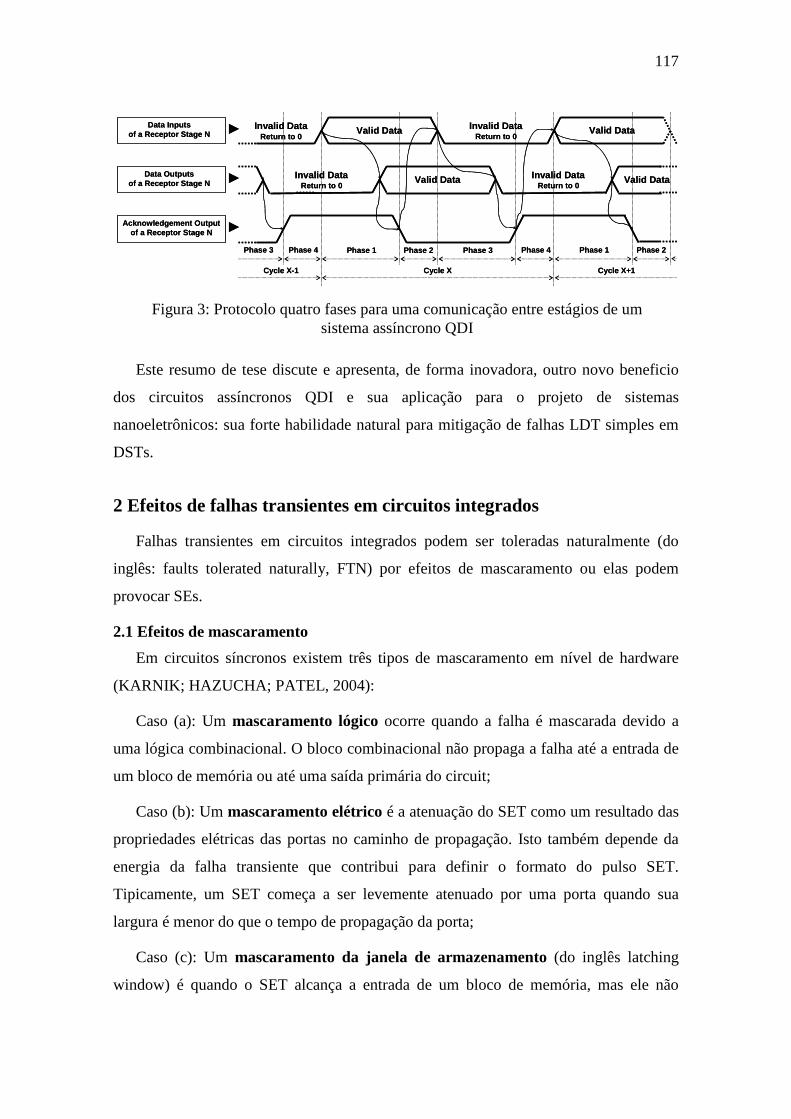
117
Este resumo de tese discute e apresenta, de forma inovadora, outro novo beneficio
dos circuitos assíncronos QDI e sua aplicação para o projeto de sistemas
nanoeletrônicos: sua forte habilidade natural para mitigação de falhas LDT simples em
DSTs.
2 Efeitos de falhas transientes em circuitos integrados
Falhas transientes em circuitos integrados podem ser toleradas naturalmente (do
inglês: faults tolerated naturally, FTN) por efeitos de mascaramento ou elas podem
provocar SEs.
2.1 Efeitos de mascaramento
Em circuitos síncronos existem três tipos de mascaramento em nível de hardware
(KARNIK; HAZUCHA; PATEL, 2004):
Caso (a): Um mascaramento lógico ocorre quando a falha é mascarada devido a
uma lógica combinacional. O bloco combinacional não propaga a falha até a entrada de
um bloco de memória ou até uma saída primária do circuit;
Caso (b): Um mascaramento elétrico é a atenuação do SET como um resultado das
propriedades elétricas das portas no caminho de propagação. Isto também depende da
energia da falha transiente que contribui para definir o formato do pulso SET.
Tipicamente, um SET começa a ser levemente atenuado por uma porta quando sua
largura é menor do que o tempo de propagação da porta;
Caso (c): Um mascaramento da janela de armazenamento (do inglês latching
window) é quando o SET alcança a entrada de um bloco de memória, mas ele não
Invalid DataReturn to 0
Valid Data
Valid Data Valid DataInvalid DataReturn to 0
Data Outputsof a Receptor Stage N
Acknowledgement Output of a Receptor Stage N ►
►
Valid DataInvalid DataReturn to 0
Data Inputsof a Receptor Stage N ► Invalid Data
Return to 0
Phase 1 Phase 2 Phase 3 Phase 4 Phase 1 Phase 2Phase 4Phase 3
Cycle X Cycle X+1Cycle X-1
Figura 3: Protocolo quatro fases para uma comunicação entre estágios de um sistema assíncrono QDI

118
encontra a janela temporal, tais como os tempos de set-up e hold ou o sinal de enable,
requeridos para memorizar um valor lógico;
Os casos (a) e (b) ocorrem da mesma forma para circuitos assíncronos QDI. Além
deles, existem dois outros tipos de mascaramento em circuitos QDI (MONNET;
RENAUDIN; LEVEUGLE, 2006-c):
Caso (d): Um mascaramento através da capacidade de filtragem do C-element
acontece quando um SET chega em uma entrada de um C-element, mas ele não é
memorizado. A razão é que uma outra entrada apresenta um valor diferente daquela
entrada com o SET, assim a saída do C-element não é modificada e o SET é mascarado;
Caso (e) Outro mascaramento é as ações do protocolo de comunicação por meio de
uma tolerância natural a falhas de atraso induzidas por SETs. Isto ocorre quando
um SET é memorizado por um C-element, ou seja, um soft error acontece, mas o
mesmo valor armazenado, mais cedo ou mais tarde, seria memorizado de qualquer
maneira em condições normais livres de falhas. Assim, uma falha de atraso é induzida
na saída do C-element. Contudo, tal memorização prematura ou atrasada é naturalmente
tolerada pela propriedade QDI do circuito.
2.2 Failures: os efeitos dos soft errors
Soft errors implicam na maioria das vezes em um failure apresentado nas saídas
primárias de um circuito de um sistema. Isto significa que um soft error levaria à
computação de um resultado inconsistente ilustrado nas saídas primárias do circuito (do
inglês: circuit’s primary outputs, CPOs).
Quando um circuito é capaz de indicar o término da computação de resultados por
uma saída primária específica (por exemplo, um sinal de fim de operação SEO, do
inglês signal of end operation), eventuais failures nas suas saídas primárias de
resultados podem ser detectados naturalmente pelo sistema sem a necessidade de
qualquer mecanismo adicional em hardware específico para detecção.
Dessa forma, dois tipos de failure são definidos:
• Failure Detectável Naturalmente (FDN): a detecção natural de um failure
ocorre se o sinal de fim de operação SEO não é indicado dentro de um período
estimado superior ao tempo total de computação para obter um resultado. Nesse
cenário de failure, módulos periféricos vizinhos como também aplicações de

119
software do sistema normalmente perceberiam a ausência de tal indicação e,
assim, o failure se propagaria naturalmente para níveis de abstração superiores
(exemplo: aplicações de software), onde o sistema poderia facilmente tanto
detectá-lo como corrigi-lo por recomputação. Na verdade, a detecção em nível
de software, por exemplo, por mecanismos de monitoração por tempo de
interrupção (do inglês timeout) e uma consequente solicitação de recomputação
facilmente eliminariam tal failure;
• Failure Não-detectável Naturalmente (FNN): um eventual failure em outras
CPOs, que fornecem resultados de dados ou endereços, por exemplo, não pode
ser detectado naturalmente se o circuito indica o sinal de fim de operação SEO
dentro do período estimado, logo mecanismos adicionais em hardware precisam
ser implementados para viabilizar detecções de failures sem usar custosas
técnicas baseadas em softwares.
3 Detecção natural de failures
A maioria dos circuitos integrados controla a quantidade de ciclos de iteração e
indica um sinal de saída no fim da operação (SEO), dessa forma uma eventual carência
de indicação devido a um failure é facilmente detectável pelo sistema, ou seja, como
definido na seção anterior, o failure é detectável naturalmente (FDN) sem requerer
qualquer hardware adicional e facilmente corrigido por recomputação. Pelo outro lado,
se o SEO é bem indicado e um failure surge nas outras CPOs, o failure é não-detectável
naturalmente (FDN) e assim extras mecanismos de hardware para detecção são
necessários para mitigá-lo sem ter altos custos com software. Tabela 1 sumariza esses
efeitos de falhas transientes de acordo com as CPOs.
Tabela 1: Possiveis CPOs de um sistema perturbado por falhas transientes
Valores nas CPOs Consequência
SEO Outras CPOs OK OK FTN
Inconsistente OK FDN Inconsistente Inconsistente FDN
OK Inconsistente FNN

120
3.1 Habilidade dos sistemas assíncronos QDI
Diferentemente dos circuitos síncronos, os circuitos assíncronos QDI tem uma
habilidade natural para transformar a maioria dos casos de SE em FDN em qualquer
tecnologia de fabricação de circuito integrado. Isso significa que a maior parte das
situações de failure são detectáveis pelo sistema QDI sem qualquer hardware extra. Tal
propriedade natural de um circuito QDI é justificada pela sua arquitetura.
Uma arquitetura QDI controla a sequência do seu fluxo de dados no final de cada
um dos seus ciclos de iteração. Cada ciclo precisa ter todas as fases do protocolo de
handshaking, como ilustrado na Figura 3, por exemplo. Qualquer evento que perturbe as
fases do protocolo pode levar o sistema a perder sua correta sequência de dados. Tal
perda de sincronização entre fases de um ciclo induz um bloqueio (do inglês deadlock)
sobre o fluxo de dados do sistema na maioria dos casos de SE (MONNET;
RENAUDIN; LEVEUGLE, 2007-b; MOORE et al., 2003). Na verdade, um ciclo de
iteração não finaliza com sucesso seu objetivo e assim um elemento de dado é perdido
ou um adicional é inserido.
Normalmente, no protocolo quatro fases, uma situação de deadlock acontece quando
um SE ocorre em um elemento de memória de um estágio N de um sistema chaveando
de/para um dado válido ou proibido para/de um dado inválido. Tal cenário na realidade
gera um acknowledgment errado (ou seja, um acknowledgment em estado lógico
oposto) para o estágio prévio N-1 do sistema. Assim, por exemplo, um dado válido em
um elemento de memória de um estágio N pode ser perdido (ou seja, tornar-se um dado
inválido) antes que o próximo estágio N+1 tenha processado e feito acknowledgment
dele. Como pior consequência, a correta comunicação entre estágios é quebrada e um
deadlock é caracterizado.
Em uma primeira impressão, tal cenário de deadlock pode parecer um
comportamento que desqualifique os sistemas QDI. Entretanto, a maioria das
arquiteturas QDI contam seus elementos de dados ou ainda a quantidade de ciclos de
iteração a fim de indicar um SEO. Portanto, um eventual deadlock sempre perturba tal
contagem e assim não há indicação de SEO e um FDN sempre acontece. Pelo outro
lado, quase todos os casos de FNN são facilmente detectáveis através da implementação
de mecanismos de alarme de baixo custo (MONNET; RENAUDIN; LEVEUGLE,

121
2006-c; 2007-b; MOORE et al., 2003) que identificam estados de dados proibidos no
protocolo.
Na realidade, os caminhos de dados multi rail dos circuitos QDI permitem classificar
os SEs devido a falhas transientes únicas em três casos (MONNET; RENAUDIN;
LEVEUGLE, 2006-c; 2007-b):
• Dado gerado: um elemento de dado inválido torna-se um elemento de dado
válido, por exemplo, o bloco de memória dual rail na Figura 2 trocando um bit
como 00=>01 ou 00=>10;
• Dado desaparecido: um elemento de dado válido para um elemento de dado
inválido, por exemplo, 01=>00 ou 10=>00; e
• Dado corrompido: um elemento de dado proibido é gerado, por exemplo,
01=>11 ou 10=>11.
Todos os casos de dados corrompidos causam um FNN porque um dado proibido é
interpretado pelo sistema como um dado válido, assim o estado lógico do
acknowledgment não é modificado e um deadlock não acontece. Tais casos de FNN
são, entretanto, detectáveis pela adição de um bastante simples circuito de alarme
(MOORE et al., 2003). Pelo outro lado, somente poucos casos de dados gerados e dados
desaparecidos não resultam em deadlock, ou seja, FNN (MONNET; RENAUDIN;
LEVEUGLE, 2006-c; 2007-b). Todos os outros casos, que representam a maioria de
casos de SEs, produzem FDN.
Como os efeitos nocivos de falhas transientes são FDN ou FNN de acordo com a
Tabela 1, assim a maioria das situações de failure em sistemas assíncronos QDI podem
ser facilmente mitigadas ou por detecção natural ou por mecanismos de alarme.
3.2 Inabilidade dos sistemas síncronos
Pelo outro lado, casos de SEs em circuitos síncronos dificilmente resultam em FDN.
Como consequência, a maior parte dos SEs causam FNN e assim sistemas síncronos
praticamente não tem aquela propriedade natural para detecção.
Notadamente, a presença de um período fixo de relógio assegura a sincronização dos
dados do sistema. Portanto, em contraste com as discussões da seção prévia para os
circuitos assíncronos QDI, na maioria dos casos de SEs, o SEO é indicado e assim um

122
FNN é gerado ao invés de um FDN. Casos de FNN são assim predominantes em
circuitos síncronos.
Os poucos casos de geração de FDN são principalmente atribuídos a perturbações
nos registradores que contam o número de ciclos de iteração, já que tais elementos de
memória auxiliam na implementação do SEO. Alem disso, falhas transientes, ou em
circuitos combinacionais que gerem esse SEO ou em circuitos da árvore de relógio,
podem também causar FDN.
4 Mitigação de múltiplas falhas transientes
Múltiplos eventos de perturbação ou mesmo eventos únicos podem criar múltiplas
falhas transientes. Tais situações de falha, que são de mais baixa probabilidade do que
as falhas transientes únicas, podem criar mais severos efeitos nocivos porque mais de
um bloco de memória pode ser perturbado e assim múltiplos soft errors podem ser
gerados tanto em circuitos síncronos quanto em circuitos assíncronos QDI. Na
realidade, falhas transientes podem perturbar diferentes blocos de memória (como
aqueles elementos de memória na Figura 2) tanto simultaneamente como também em
diferentes instantes.
Os efeitos nocivos de múltiplas falhas transientes seriam mais críticos se suas
probabilidades de ocorrência fossem maiores. Na verdade os sistemas teriam que ser
protegidos usando ainda mais redundância para enfrentar tal fenômeno.
Além disso, como técnicas de mitigação são baseadas em redundância, falhas
ocorrendo simultaneamente em partes redundantes podem confundir os elementos de
detecção (que fazem a técnica trabalhar corretamente) levando-os a falhar. A maioria
das abordagens de mitigação são assim vulneráveis aos efeitos nocivos de múltiplas
falhas transientes.
A análise dos efeitos de múltiplas falhas transientes em circuitos síncronos é
bastante similar às discussões salientadas na seção anterior. Contudo, como há mais
eventos de falhas no sistema, a probabilidade de ocorrências de SEs devido a múltiplas
falhas transientes, e assim de um FNN, é obviamente maior do que nos casos de
ocorrência de falhas transientes únicas.

123
Pelo outro lado, em sistemas assíncronos QDI, a ocorrência de múltiplas falhas em
diferentes blocos de memória (como na Figura 2) também segue as mesmas
consequências discutidas na seção anterior, assim há uma grande chance que eles
resultem em FDN. O mesmo cenário acontece se múltiplas falhas transientes ocorrem
em diferentes instantes.
Contudo, múltiplas falhas transientes ocorrendo no mesmo bloco de memória de um
sistema QDI podem também resultar em múltiplos SEs e assim para uma codificação
dual rail, por exemplo, elas causam FNN na maioria dos casos. Na realidade, as
situações de SEs são: 00=>11, que é um caso de dado corrompido que provavelmente
gera um deadlock (ou seja, um FDN) porque o estado lógico do acknowledgment é
modificado; e 01=>10, ou 10=>01, que normalmente não produzem deadlocks (portanto
FNN) porque elas mantem o estado lógico do acknowledgment. Monnet (2006-c) assim
classifica um caso a mais de SE em relação aqueles apresentados na seção anterior para
falhas transientes únicas em sistemas QDI:
• Dado modificado: um elemento de dado válido é revertido para outro elemento
de dado válido, por exemplo, 01=>10 ou 10=>01.
Infelizmente casos de dados modificados não tem uma solução natural para serem
mitigados e, dessa forma, eles requerem mecanismos de mitigação suplementares.
Contudo, como bem discutido na seção anterior, os casos de dados corrompidos que não
se tornam um FDN são facilmente detectáveis por um mecanismo de alarme de baixo-
custo (MOORE et al., 2003).
Além disso, através do uso de codificação M-out-of-N (multi-rail), que é bastante
normal em projetos de circuitos QDI, as chances casos de dados corrompidos são muito
maiores, visto que haverá uma maior redundância da codificação. Portanto, a
probabilidade que dados proibidos ocorram é maior e, dessa forma, mais casos de SEs
são detectáveis através do mecanismo de alarme ou mesmo gerando naturalmente
deadlocks (FDN). Uma solução, portanto, para reduzir casos de dados modificados é
usar uma maior codificação M-out-of-N do que o dual rail (ou seja, 1-out-of-2).
Mesmo que sistemas assíncronos QDI sob múltiplas falhas transientes não tenham a
mesma performance para gerar FDN do que situações de falhas transientes únicas, eles
tem, contudo, melhores mecanismos naturais para a mitigação de tais falhas múltiplas
do que circuitos síncronos.
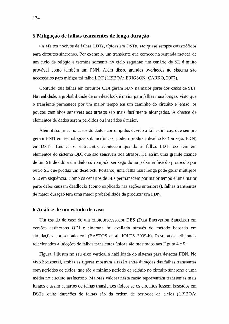
124
5 Mitigação de falhas transientes de longa duração
Os efeitos nocivos de falhas LDTs, típicas em DSTs, são quase sempre catastróficos
para circuitos síncronos. Por exemplo, um transiente que comece na segunda metade de
um ciclo de relógio e termine somente no ciclo seguinte: um cenário de SE é muito
provável como também um FNN. Além disso, grandes overheads no sistema são
necessários para mitigar tal falha LDT (LISBOA; ERIGSON; CARRO, 2007).
Contudo, tais falhas em circuitos QDI geram FDN na maior parte dos casos de SEs.
Na realidade, a probabilidade de um deadlock é maior para falhas mais longas, visto que
o transiente permanece por um maior tempo em um caminho do circuito e, então, os
poucos caminhos sensíveis aos atrasos são mais facilmente alcançados. A chance de
elementos de dados serem perdidos ou inseridos é maior.
Além disso, mesmo casos de dados corrompidos devido a falhas únicas, que sempre
geram FNN em tecnologias submicrônicas, podem produzir deadlocks (ou seja, FDN)
em DSTs. Tais casos, entretanto, acontecem quando as falhas LDTs ocorrem em
elementos do sistema QDI que são sensíveis aos atrasos. Há assim uma grande chance
de um SE devido a um dado corrompido ser seguido na próxima fase do protocolo por
outro SE que produz um deadlock. Portanto, uma falha mais longa pode gerar múltiplos
SEs em sequência. Como os cenários de SEs permanecem por maior tempo e uma maior
parte deles causam deadlocks (como explicado nas seções anteriores), falhas transientes
de maior duração tem uma maior probabilidade de produzir um FDN.
6 Análise de um estudo de caso
Um estudo de caso de um criptoprocessador DES (Data Encryption Standard) em
versões assíncrona QDI e síncrona foi avaliado através do método baseado em
simulações apresentado em (BASTOS et al, IOLTS 2009-b). Resultados adicionais
relacionados a injeções de falhas transientes únicas são mostrados nas Figura 4 e 5.
Figura 4 ilustra no seu eixo vertical a habilidade do sistema para detectar FDN. No
eixo horizontal, ambas as figuras mostram a razão entre durações das falhas transientes
com períodos de ciclos, que são o mínimo período de relógio no circuito síncrono e uma
média no circuito assíncrono. Maiores valores nesta razão representam transientes mais
longos e assim cenários de falhas transientes típicos se os circuitos fossem baseados em
DSTs, cujas durações de falhas são da ordem de períodos de ciclos (LISBOA;
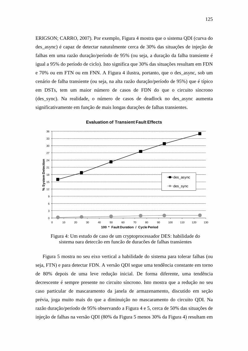
125
ERIGSON; CARRO, 2007). Por exemplo, Figura 4 mostra que o sistema QDI (curva do
des_async) é capaz de detectar naturalmente cerca de 30% das situações de injeção de
falhas em uma razão duração/período de 95% (ou seja, a duração da falha transiente é
igual a 95% do período de ciclo). Isto significa que 30% das situações resultam em FDN
e 70% ou em FTN ou em FNN. A Figura 4 ilustra, portanto, que o des_async, sob um
cenário de falha transiente (ou seja, na alta razão duração/período de 95%) que é típico
em DSTs, tem um maior número de casos de FDN do que o circuito síncrono
(des_sync). Na realidade, o número de casos de deadlock no des_async aumenta
significativamente em função de mais longas durações de falhas transientes.
Figura 5 mostra no seu eixo vertical a habilidade do sistema para tolerar falhas (ou
seja, FTN) e para detectar FDN. A versão QDI segue uma tendência constante em torno
de 80% depois de uma leve redução inicial. De forma diferente, uma tendência
decrescente é sempre presente no circuito síncrono. Isto mostra que a redução no seu
caso particular de mascaramento da janela de armazenamento, discutido em seção
prévia, joga muito mais do que a diminuição no mascaramento do circuito QDI. Na
razão duração/período de 95% observando a Figura 4 e 5, cerca de 50% das situações de
injeção de falhas na versão QDI (80% da Figura 5 menos 30% da Figura 4) resultam em
Figura 4: Um estudo de caso de um cryptoprocessador DES: habilidade do sistema para detecção em função de durações de falhas transientes
0
3
6
9
12
15
18
21
24
27
30
33
36
0 10 20 30 40 50 60 70 80 90 100 110 120 130
% S
yste
m D
etec
tion
100 * Fault Duration / Cycle Period
Evaluation of Transient Fault Effects
des_async
des_sync
126
FTN, 30% FDN (da Figura 4) e 20% FNN (100% menos 80% da Figura 5). Pelo outro
lado, a versão síncrona na mesma condição de DST apresenta FTN em 42% das
situações, FDN em 1% e FNN em 57%. Se a versão QDI fosse implementada com
alarmes (MOORE et al., 2003), a sua habilidade na Figura 5 alcançaria muito próximo
de 100% mesmo sob falhas LDTs em DSTs. Dessa forma, fica claro concluir que falhas
LDTs em DSTs podem ser melhores tratadas no circuito assíncrono QDI.
6 Conclusões
Este resumo de tese ilustra pela primeira vez a habilidade natural dos circuitos
assíncronos QDI para mitigar falhas transientes sob condições de DSTs. Sistemas QDI
tem uma melhor performance do que seus equivalentes síncronos para naturalmente
detectar falhas LDTs tanto em lógica computacional quanto em elementos de memória.
Além disso, eles tem mecanismos naturais (na realidade a codificação multi-rail e seus
elementos de dados proibidos) que facilitam a detecção de erro mesmo sob falhas
transientes múltiplas. Por fim, sistemas QDI agregam tais características com sua
propriedade QDI natural. Isto permite tolerar a maioria dos casos de falhas de atraso,
que hoje são também um grande desafio em DSTs.
35
40
45
50
55
60
65
70
75
80
85
90
95
0 10 20 30 40 50 60 70 80 90 100 110 120 130
% S
yste
m T
oler
ance
+ %
Sys
tem
Det
ectio
n
100 * Fault Duration / Cycle Period
Evaluation of Transient Fault Effects
des_async
des_sync
Figura 5. A mais forte habilidade natural de um sistema assincrono QDI para mitigação de falhas LDTs em DSTs

APPENDIX B SYSTEMES ROBUSTES AUX FAUTES TRANSITOIRES EXPLOITANT LA LOGIQUE
ASYNCHRONE QUASI-INSENSIBLE AUX DELAIS
Résumé de la Thèse en Français
1 Introduction
Les technologies submicroniques profondes (de l'anglais: deep-submicron
technologies, DSTs) pour la fabrication de circuits intégrés ont indéniablement
révolutionné la conception des systèmes électroniques. Toutefois, elles imposent
également des défis considérables pour la fiabilité des circuits intégrés. En fait,
aujourd'hui, les circuits nanoélectroniques sont plus sensibles aux variations du
processus de fabrication ainsi que des facteurs environnementaux comme la
température, les radiations et le bruit électrique. Plus notamment, les circuits intégrés
modernes sont beaucoup plus vulnérables à deux principaux effets de ces variations: les
altérations temporaires des délais des circuits, appelées les fautes de délais; et les
modifications transitoires de voltage, connues comme les fautes transitoires.
Ces deux types de fautes, mais surtout les fautes transitoires peuvent perturber le
fonctionnement des circuits intégrés provoquant des inversions des bits de mémoire
connues sous le nom en anglais soft errors (SEs) (KARNIK; HAZUCHA; PATEL,
2004). Si propagées, ces erreurs peuvent entraîner le circuit à produire des résultats
incohérents en ses sorties primaires rendant ainsi un scénario connu en anglais comme
circuit's failure. Ces fautes ont des effets encore plus graves dans les DSTs, où il est
possible que les durées de fautes soient comparables ou même plus longues que les
périodes de cycles d'horloge (LISBOA; ERIGSON; CARRO, 2007), comme illustré
dans la Figure 1. En outre, la plupart des techniques de protection existantes
(NICOLAIDIS, 1999; IYER et al, 2005) exigent des surcoûts très hautes pour faire face

128
à ces fautes transitoires de longue durée (de l'anglais: long-duration transient, LDT) et
donc de nouvelles solutions pour protéger les circuits sont nécessaires (LISBOA;
ERIGSON; CARRO, 2007).
Les fautes LDTs ont clairement une probabilité beaucoup plus élevée de ne pas être
masquées et donc ils ont aussi plus de chances de produire un circuit's failure. En
réalité, cette probabilité plus élevée d'erreur est due à la limitation de la période
d'horloge qui est ainsi fondamentale pour la gravité des fautes de délai et des fautes
transitoires. D'autre part, l'horloge est une particularité des circuits synchrones
traditionnels qui souffrent donc beaucoup plus avec les pires conséquences des LDTs
que les circuits sans horloge. Par conséquent, la conception de circuits qui ne sont pas
contrôlés par une horloge globale, mais seulement par leur fluxes de données internes,
peut entraîner en systèmes qui sont plus robustes contre ces fautes LDTs. Cela est le cas
des circuits asynchrones et spécialement leur plus importante classe: les circuits quasi-
insensibles aux délais (de l'anglais: Quasi-Delay Insensitive, QDI) (LAFRIEDA;
MANOHAR, 2004; JANG; MARTIN, 2005; PENG; MANOHAR, 2005; MONNET;
RENAUDIN; LEVEUGLE, 2006; KUANG et al, 2007; GARDINER; YAKOVLEV;
BYSTROV, 2007; ALMUKHAIZIM; SHI; MAKRIS, 2008; KUANG et al, 2010).
Essentiellement les circuits QDI sont composés de C-éléments, aussi connus comme
les portes de Muller. La fonction d'un C-élément est simplement comparer les états
logiques de ses entrées. Lorsque les entrées sont identiques, l'état de sa sortie sera mis à
jour afin de refléter l'état des ses entrées. Le C-élément dans cet état fonctionne comme
un buffer. Dans le cas où ses entrées ne sont pas identiques, l'état de sortie sera préservé.
Dans ce cas-là le C-élément fonctionne comme un élément de mémoire.
Ce type de porte assure la propriété QDI et permet la synchronisation entre les
différents stages du circuit, comme montré dans la Figure 2, où un typique protocole de
Figure 1: Une faute transitoire de longue durée (LDT)
Any circuitAny circuit’’s node:s node:
CircuitCircuit’’s clock:s clock:
Any circuitAny circuit’’s node:s node:
CircuitCircuit’’s clock:s clock:

129
handshaking, basé en quatre phases, est appliqué dans un chemin de données double
rail. Le protocole détaillé dans la Figure 3 impose en fait une phase de retour à zéro
entre les requêtes de données et donc une donnée invalide (exemple double rail: 00), des
données valides (exemple: 01; 10) et une donnée interdite (11, en cas d'erreur) sont
possibles sur le chemin de données.
Le schéma de codification multi-rail et la communication asynchrone par
handshaking de systèmes QDI permettent une plus facile détection et correction de
erreurs (MONNET; RENAUDIN; LEVEUGLE, 2006). L'absence d'un arbre d'horloge
permet à ces systèmes d'émettre moins interférences électromagnétiques et les rend plus
sécurisés contre les analyses malicieuses de leurs puissances (BOUESSE et al, 2004).
En outre, cette propriété entraîne également des augmentations dans l'économie
d'énergie, et la réalisation de hautes performances aux coûts de l'utilisation de moins de
deux fois plus grande superficie que leurs homologues synchrones. Un circuit QDI est
aussi intrinsèquement robuste aux fautes de délais dans la plupart de ses chemins
(LAFRIEDA; MANOHAR, 2004). Par ailleurs, ses C-éléments sont fondamentaux pour
mettre en œuvre systèmes plus robustes. En fait, même dans les systèmes synchrones,
C-éléments sont souvent utilisés pour filtrer les fautes transitoires et donc protéger les
circuits contre SEs (NICOLAIDIS, 1999; MITRA et al, 2005; FAZELI et al, 2007). Par
conséquent, C-éléments de systèmes QDI améliorent la capacité du circuit de masquage
de fautes transitoires (MONNET; RENAUDIN; LEVEUGLE, 2006), mais ils font aussi
les blocs de mémoire des systèmes QDI et donc ils sont également directement sensibles
aux SEs (MONNET; RENAUDIN; LEVEUGLE, 2006-c).
Stage C
C C
C
C C
A0
A1
AB_ack
B1
B0
S1
S0
S_ack
Computational Logic Block
Computational Logic Block
Computational L ogic Block = Dual-Rail XOR
Memory Block Memory
Block
Memory Block
Figure 2: Un circuit QDI fonctionnant à partir du protocole quatre phases

130
Ce résume de thèse discute et présente, de façon innovante, un autre avantage des
circuits asynchrones QDI et leur application pour la conception de systèmes
nanoélectroniques: leur forte capacité naturelle pour résister aux fautes LDTs unique en
DSTs.
2 Les effets de fautes transitoires dans les circuits intégrés
Les fautes transitoires dans les circuits intégrés peuvent être tolérées naturellement
(de l'anglais: faults tolerated naturally, FTN) par des effets de masquage ou ils peuvent
provoquer des SEs.
2.1 Les effets de masquage
Dans les circuits synchrones il y a trois types d'effets de masquage au niveau
matériel (KARNIK; HAZUCHA; PATEL, 2004):
Cas (a): Un masquage logique se produit lorsque la faute est masquée en raison
d'une logique combinatoire. Le bloc combinatoire ne propage pas la faute à l'entrée d'un
bloc de mémoire ou à une sortie primaire du circuit;
Cas (b): Un masquage électrique est une atténuation du SET comme une
conséquence des propriétés électriques des portes dans le chemin de propagation. Cela
dépend aussi de l'énergie du SET qui contribue pour définir la forme du pulse SET.
Typiquement, un SET commence à être légèrement atténué par une porte lorsque sa
durée est inférieure au temps de propagation de la porte;
Cas (c): Un masquage de la fenêtre de stockage (de l'anglais latching window) est
quand l'SET atteint l'entrée d'un bloc de mémoire, mais il ne trouve pas la fenêtre de
Invalid DataReturn to 0
Valid Data
Valid Data Valid DataInvalid DataReturn to 0
Data Outputsof a Receptor Stage N
Acknowledgement Output of a Receptor Stage N ►
►
Valid DataInvalid DataReturn to 0
Data Inputsof a Receptor Stage N ► Invalid Data
Return to 0
Phase 1 Phase 2 Phase 3 Phase 4 Phase 1 Phase 2Phase 4Phase 3
Cycle X Cycle X+1Cycle X-1
Figure 3: Protocole quatre phases pour une communication entre stages d’un système asynchrone QDI

131
temps, comme les temps de set-up et hold ou le sinal de enable, qui sont nécessaires
pour mémoriser une valeur logique;
Cas (a) et (b) se produisent de la même manière pour les circuits asynchrones QDI.
Par ailleurs, il y a deux autres types d'effets de masquage dans les circuits asynchrones
QDI (MONNET; RENAUDIN; LEVEUGLE, 2006-c):
Cas (d): Un masquage grâce à la capacité de filtrer du C-élément qui se passe
quand un SET arrive à l'entrée d'un C-élément, mais il n'est pas mémorisé. La raison est
qu'une autre entrée a une valeur logique différente de celle avec l'SET, par conséquent,
la sortie du C-élément n'est pas modifiée et le SET est masqué;
Cas (e): Un autre masquage est les actions du protocole de communication à partir
d'une tolérance naturelle aux fautes de délais induites par SETs. Cela se produit
quand un SET est mémorisé par un C-élément, c'est-à-dire, un soft error se produit, mais
la même valeur logique serait, plus tôt ou plus tard, stockée en mémoire de toute façon
sous des conditions normales sans fautes. Par conséquent, une faute de délais est induite
dans la sortie du C-élément. Néanmoins, cette mémorisation prématurée ou retardée est
presque toujours naturellement tolérée par la propriété QDI du circuit.
2.2 Les failures: les effets des soft errors
Soft errors imposent dans la plupart des cas un failure aux sorties primaires d'un
circuit d'un système. Cela signifie qu'un soft error conduit au calcul d'un résultat
inconsistant illustré aux sorties primaires du circuit (de l'anglais: circuit’s primary
outputs, CPOs).
Si un circuit est en mesure d'indiquer la fin du calcul des résultats par une sortie
primaire spécifique (par exemple, un signal de la fin de l'opération SEO, de l'anglais:
signal of end operation), éventuels failures aux sorties primaires de résultats peuvent
être naturellement détecté par le système sans nécessiter de quelconque mécanisme
supplémentaire au niveau matériel spécifique pour la détection.
Par conséquent, deux types de failures sont définis:
• Failure Détectable Naturellement (FDN): la détection naturelle d'un failure se
produit si le signal de la fin de l''opération SEO n'est pas indiqué dans un délai
estimé supérieur au temps total de calcul pour obtenir un résultat. Dans ce
scénario de failure, modules périphériques à proximité ainsi que les applications
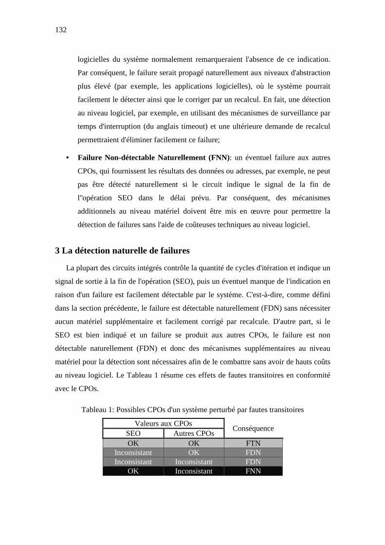
132
logicielles du système normalement remarqueraient l'absence de ce indication.
Par conséquent, le failure serait propagé naturellement aux niveaux d'abstraction
plus élevé (par exemple, les applications logicielles), où le système pourrait
facilement le détecter ainsi que le corriger par un recalcul. En fait, une détection
au niveau logiciel, par exemple, en utilisant des mécanismes de surveillance par
temps d'interruption (du anglais timeout) et une ultérieure demande de recalcul
permettraient d'éliminer facilement ce failure;
• Failure Non-détectable Naturellement (FNN): un éventuel failure aux autres
CPOs, qui fournissent les résultats des données ou adresses, par exemple, ne peut
pas être détecté naturellement si le circuit indique le signal de la fin de
l''opération SEO dans le délai prévu. Par conséquent, des mécanismes
additionnels au niveau matériel doivent être mis en œuvre pour permettre la
détection de failures sans l'aide de coûteuses techniques au niveau logiciel.
3 La détection naturelle de failures
La plupart des circuits intégrés contrôle la quantité de cycles d'itération et indique un
signal de sortie à la fin de l'opération (SEO), puis un éventuel manque de l'indication en
raison d'un failure est facilement détectable par le système. C'est-à-dire, comme défini
dans la section précédente, le failure est détectable naturellement (FDN) sans nécessiter
aucun matériel supplémentaire et facilement corrigé par recalcule. D'autre part, si le
SEO est bien indiqué et un failure se produit aux autres CPOs, le failure est non
détectable naturellement (FDN) et donc des mécanismes supplémentaires au niveau
matériel pour la détection sont nécessaires afin de le combattre sans avoir de hauts coûts
au niveau logiciel. Le Tableau 1 résume ces effets de fautes transitoires en conformité
avec le CPOs.
Tableau 1: Possibles CPOs d'un système perturbé par fautes transitoires
Valeurs aux CPOs Conséquence
SEO Autres CPOs OK OK FTN
Inconsistant OK FDN Inconsistant Inconsistant FDN
OK Inconsistant FNN

133
3.1 L’habilité des systèmes asynchrones QDI
Contrairement aux circuits synchrones, les circuits asynchrones QDI ont une habilité
naturelle à transformer la plupart des cas de SE en FDN, quelle que soit la technologie
de fabrication de circuit intégré. Cela signifie que la plus grande partie des situations de
failure sont détectables par le système QDI sans aucun dispositif matériel
supplémentaire. Cette propriété naturelle d'un circuit QDI est justifiée par son
architecture.
Une architecture QDI contrôle la séquence de son flux de données à la fin de chacun
de ses cycles d'itération. Chaque cycle doit avoir toutes les phases du protocole de
handshaking, comme illustré dans la Figure 3, par exemple. Tout événement qui
perturbe les phases du protocole peut conduire le système à perdre de sa séquence
correcte des données. Cette perte de synchronisation entre les phases d'un cycle induit
un blocage (du anglais deadlock) sur le flux de données du système dans la plupart des
cas de SE (MONNET; RENAUDIN; LEVEUGLE, 2007-b; MOORE et al, 2003). En
effet, un cycle d'itération ne parvient pas à terminer son objectif et donc un élément de
donnée est perdu ou un autre supplémentaire est inséré.
Normalement, dans le protocole en quatre phases, une situation de deadlock se
produit quand un SE est généré dans un élément de mémoire d'un stage N d'un système
en commutant de / vers une donnée valide ou interdite vers / de une donnée invalide. Ce
scénario génère en effet un acquittement erroné (c'est-à-dire, un acquittement à l'état
logique inverse) vers le stage précédent N-1 du système. Alors, par exemple, une
donnée valide dans un élément de mémoire de le stage N d'un système peut être perdu
(c'est-à-dire, devenir une donnée invalide) avant que le stage suivant N+1 du système ait
traité et fait le acquittement de lui. Comme la pire conséquence, la communication entre
les stages est cassée et un deadlock est caractérisé.
Dans une première impression, ce scénario de deadlock peut sembler un
comportement qui disqualifie les systèmes QDI. Toutefois, la majorité des architectures
QDI comptent leurs éléments de données ou même la quantité de cycles d'itération afin
de signaler un SEO. Par conséquent, un éventuel deadlock toujours perturbe ce compte
et ainsi il n'y a pas indication de SEO et un FDN arrive toujours. D'autre part, la quasi-
totalité des cas de FNN sont facilement détectables par la mise en œuvre des
mécanismes d'alarme à faible coût (MONNET; RENAUDIN; LEVEUGLE, 2006-c;

134
2007-b; MOORE et al, 2003), qui identifient les états de données interdits dans le
protocole.
En fait, les chemins de données multi rail des circuits QDI permettent classer les SEs
en raison du à fautes transitoires uniques dans trois cas (MONNET; RENAUDIN;
LEVEUGLE, 2006-c; 2007-b):
• Donnée générée: un élément de donnée invalide devient un élément de donnée
valide, par exemple, le bloc de mémoire dual rail de la Figure 2 changeant un bit
comme 00=>01 ou 00=>10;
• Donnée disparue: un élément de donnée valide vers un élément de donnée
invalide, par exemple, 01=>00 ou 10=>00, et
• Donnée corrompue: un élément de donnée interdite est généré, par exemple,
01=>11 ou 10=>11.
Tous les cas de données corrompues causent un FNN car une donnée interdite est
interprétée par le système comme une donnée valide, ainsi l'état logique de
l’acquittement n'est pas modifié et un deadlock ne se produit pas. Ces cas de FNN sont,
cependant, détectables en ajoutant un très simple circuit d'alarme (MOORE et al, 2003).
D'autre part, seulement quelques cas de données générées et de données disparues ne
produisent pas un deadlock, c'est à dire, un FNN (MONNET; RENAUDIN;
LEVEUGLE, 2006-c; 2007-b). Tous les autres cas, qui représentent la majorité des cas
de SEs, produisent un FDN.
Comme les effets nocifs de fautes transitoires sont les FDN ou les FNN,
conformément au tableau 1, ainsi la majorité des situations de failures dans les systèmes
asynchrones QDI peuvent facilement être éliminées soit par la détection naturelle soit
par les mécanismes d'alarme.
3.2 L’inhabilité des systèmes synchrones
D'autre part, les cas de SEs dans les circuits synchrones difficilement entraînent un
FDN. Par conséquent, la plus grande partie des SEs causent un FNN et ainsi des
systèmes synchrones n'ont pratiquement aucune propriété naturelle pour la détection.
Notamment, la présence de la période fixe d'horloge garantit la synchronisation des
données du système. En conséquence, contrairement aux discussions de la section

135
précédente pour les circuits asynchrones QDI, dans la plus part des cas de SEs, le SEO
est indiqué et ainsi un FNN est généré au lieu d'un FDN. Cas de FNN sont donc
prédominant dans les circuits synchrones.
Les quelques cas de génération de FDN sont surtout attribués à des perturbations
dans les registres qui comptent le nombre de cycles d'itération, car ces éléments de
mémoire aident dans la mise en œuvre du SEO. En outre, fautes transitoires, soit dans
les circuits combinatoires qui génèrent ce SEO soit dans les circuits de l'arbre d'horloge,
peut également causer un FDN.
4 La résistance aux multiples fautes transitoires
Des multiples événements de perturbation ou même des événements uniques
peuvent créer des multiples fautes transitoires. Ces situations de fautes, qui ont plus
faible probabilité que les fautes transitoires uniques, peuvent créer des plus graves effets
nocifs car plus d'un bloc de mémoire peut être perturbé et ainsi des multiples SEs
peuvent être générés dans les circuits synchrones bien que dans les asynchrones QDI.
En réalité, fautes transitoires peuvent perturber des différents blocs de mémoire (comme
ceux éléments de mémoire sur la Figure 2) simultanément ainsi qu'à des différents
instants.
Les effets nocifs de multiples fautes transitoires seraient plus critiques si leurs
probabilités d'occurrence fussent plus élevées. En fait les systèmes devraient être
protégés en utilisant encore plus de la redondance pour faire face à ce tel phénomène.
En outre, comme les techniques de protection sont basées en la redondance, les
fautes en se produisant simultanément dans des parties redondantes peuvent confondre
les éléments de détection (qui font la technique bien travailler) en les conduisant à
faillir. La plupart des approches de protection sont donc vulnérables aux effets des
multiples fautes transitoires.
L'analyse des effets de multiples fautes transitoires dans les systèmes synchrones est
assez semblable à la discussion mise en évidence dans la section précédente. Toutefois,
comme il y a plus des événements de fautes dans les systèmes, la probabilité
d'occurrences de SEs en raison de multiples fautes transitoires, et donc d'un FNN, est
évidemment plus élevé que dans les cas d'occurrence de fautes transitoires uniques.

136
D'autre part, dans les systèmes asynchrones QDI, l'occurrence de multiples fautes
dans différents blocs de mémoire (comme dans la Figure 2) suit également les mêmes
conséquences discutées dans la section précédente, il y a donc une chance énorme qu'ils
entrainent un FDN. Le même scénario se produit si des multiples fautes transitoires sont
générées à des instants différents.
Toutefois, des multiples fautes transitoires en se produisant dans un même bloc de
mémoire d'un système QDI peuvent également entraîner des multiples SEs et donc pour
la codification double rail, par exemple, ils provoquent un FNN dans la plupart des cas.
En réalité, les situations de SEs sont: 00=>11, qui est un cas de donnée corrompue qui
probablement génère un deadlock (c'est-à-dire, un FDN); et 01=>10, ou 10=>01, qui ne
produisent pas normalement des deadlocks (donc des FNN) car elles tiennent l'état
logique de l'acquittement. Monnet (2006-c) classifie ainsi un nouveau cas de SE, en plus
de ceux présentés dans la section précédente pour les fautes transitoires uniques dans les
systèmes de QDI:
• Donnée modifiée: un élément de donnée valide est transformé en un autre
élément de donnée valide, par exemple, 01=>10 ou 10=>01.
Malheureusement les cas de données modifiées n'ont pas une solution naturelle pour
être combattus, et donc ils nécessitent de mécanismes de protection supplémentaires.
Toutefois, comme bien discuté à la section précédente, les cas de données corrompues
qui ne devient pas un FDN sont facilement détectables par un mécanisme d'alarme à
faible coût (MOORE et al, 2003).
En outre, en utilisant la codification M-out-of-N (multi-rail), ce qui est tout à fait
normal dans la conception de circuits QDI, les chances de cas de données corrompues
sont beaucoup plus élevées, car il y aura une plus grande redondance codification. Par
conséquent, la probabilité que les données interdites se produisent est plus élevée, et
donc plus des cas de SEs sont détectables par le mécanisme d'alarme ou même en
générant naturellement des deadlocks (FDN). Une solution donc pour réduire les cas de
données modifiées est utiliser une plus élevée codification M-out-of-N que le double
rail (c'est-à-dire 1-out-of-2).
Même si les systèmes asynchrones QDI sous multiples fautes transitoires n'ont pas le
même performance pour générer des FDN que les situations de fautes transitoires

137
uniques, ils ont, néanmoins, des meilleurs mécanismes naturels de protection contre ces
multiples fautes que les circuits synchrones.
5 La résistance aux fautes transitoires de longue durée
Les effets nocifs des fautes LDT, typiques dans les DSTs, sont presque toujours
désastreux pour les circuits synchrones. Par exemple, un transitoire qui commence dans
la seconde moitié d'un cycle d'horloge et finit que dans le cycle suivant: un scénario de
SE est très probable ainsi qu'un FNN. En outre, des gros coûts dans le système sont
nécessaires pour combattre cette telle faute LDT (LISBOA; ERIGSON; CARRO,
2007).
Néanmoins, ces fautes dans les circuits QDI génèrent des FDN dans la plupart des
cas de SEs. En fait, la probabilité d'un deadlock est plus élevée pour les fautes plus
longues, vu que le transitoire reste plus longtemps dans un chemin du circuit et, donc,
les peu chemins sensibles aux délais sont facilement atteints. La chance d'éléments de
données soient perdues ou insérées est plus grande.
En outre, même des cas de données corrompues créé de fautes uniques, qui génèrent
toujours FNN dans les technologies submicroniques, peuvent produire des deadlocks
(c'est-à-dire des FDN) dans les DSTs. Ces cas, cependant, se produisent lorsque les
fautes LDT sont générées dans les éléments du système QDI qui sont sensibles aux
délais. Il y a donc une importante chance d'un SE en raison d'une donnée corrompue
être suivi dans la phase suivant du protocole par un autre SE qui produit un deadlock.
Par conséquent, une faute plus longue peut générer des multiples SEs en séquence.
Comme les scénarios de SEs restent plus longtemps et la plupart d'eux causent des
deadlocks (comme expliqué dans les sections précédentes), des fautes transitoires de
longue durée ont une probabilité plus élevée pour produire un FDN.
6 L’analyse d’une étude de cas
Une étude de cas d'un crypto-processeur DES (de l'anglais Data Encryption
Standard) en versions asynchrone QDI et synchrone a été évaluée en utilisant la
méthode basée des simulations présentée dans (BASTOS et al, IOLTS 2009-b). Des
résultats supplémentaires liés à des injections de fautes transitoires uniques sont montrés
dans les Figure 4 et 5.

138
La Figure 4 illustre à l'axe vertical l’habilité du système à détecter les FDN. À l'axe
horizontal, les deux figures indiquent le rapport des durées de fautes transitoires avec
des périodes de cycles, qui sont la minimale période d'horloge dans le circuit synchrone
et une moyenne dans le circuit asynchrone. Des plus grandes valeurs dans ce rapport
représentent transitoires plus longues et donc des scénarios typiques de fautes
transitoires si les circuits sont conçus à partir des DSTs, où les durées de fautes sont
dans l'ordre de périodes de cycles (LISBOA; ERIGSON; CARRO, 2007). Par exemple,
la Figure 4 montre que le système QDI (courbe du des_async) est capable de détecter
naturellement autour de 30% des cas d'injection de fautes dans un rapport durée/période
de 95% (c'est-à-dire, la durée de la faute transitoire est égale à 95% de la période de
cycle). Cela signifie que 30% des cas entraînent un FDN et 70% soit un FTN soit un
FNN. La Figure 4 donc illustre que le des_async, sous un scénario de faute transitoire
(c'est-à-dire, dans un élevé rapport durée/période de 95%) qui est typique dans les
DSTs, a un plus grand nombre de cas de FDN que le circuit synchrone (des_sync). En
réalité, le nombre de cas de deadlock dans le des_async augmente significativement en
fonction de plus longues durées de fautes transitoires.
Figure 4: Une étude de cas d'un crypto-processeur DES: habilité du système pour la détection en fonction de durées de fautes transitoires
0
3
6
9
12
15
18
21
24
27
30
33
36
0 10 20 30 40 50 60 70 80 90 100 110 120 130
% S
yste
m D
etec
tion
100 * Fault Duration / Cycle Period
Evaluation of Transient Fault Effects
des_async
des_sync

139
La Figure 5 montre à l'axe vertical l’habilité du système à tolérer les fautes (c'est-à-
dire, les FTN) et à détecter les FDN. La version QDI suit une tendance constante autour
de 80% après une légère réduction initiale. Au contraire, une tendance à la baisse est
toujours présente dans le circuit synchrone. Cela montre que la réduction de son cas
particulier de masquage de la fenêtre de stockage, discuté dans une section précédente,
joue beaucoup plus que la diminution de masquage du circuit QDI. Dans le rapport
durée/période de 95% en observant la Figure 4 et 5, environ 50% des cas d'injection de
fautes dans la version QDI (80% de la Figure 5 moins 30% de la Figure 4) entraînent un
FTN, 30% un FDN (à partir de la Figure 4), et 20% un FNN (100 % moins 80% de la
Figure 5). D'autre part, la version synchrone dans la même condition de DST présente
un FTN dans 42% des cas, un FDN dans 1%, et un FNN dans 57%. Si la version QDI
fût réalisée en utilisant des alarmes (MOORE et al, 2003), sa habilité de la Figure 5
serait portée très proche de 100%, même sous les fautes LDT dans les DSTs. Par
conséquent, il est évident de conclure que les fautes LDT dans les DSTs peuvent être
mieux traités dans le circuit asynchrone QDI.
35
40
45
50
55
60
65
70
75
80
85
90
95
0 10 20 30 40 50 60 70 80 90 100 110 120 130
% S
yste
m T
oler
ance
+ %
Sys
tem
Det
ectio
n
100 * Fault Duration / Cycle Period
Evaluation of Transient Fault Effects
des_async
des_sync
Figure 5. La plus forte habilité naturelle d’un système asynchrone QDI pour résister aux fautes LDT dans les DSTs

140
6 Conclusions
Ce résumé de thèse illustre pour la première fois l’habilité naturelle des circuits
asynchrones QDI pour résister aux fautes transitoires sous les conditions de DSTs. Des
systèmes QDI ont une meilleure performance que leurs homologues synchrones pour
naturellement détecter les fautes LDT soient elles dans la logique de calcul soient dans
les éléments de mémoire. En outre, ils ont des mécanismes naturels (en réalité la
codification multi-rail et ses éléments de données interdites) qui rendent plus facile la
détection d'erreurs même sous des multiples fautes transitoires. Enfin, les systèmes QDI
englobent ces caractéristiques avec leur propriété QDI naturelle. Cela permet de tolérer
la plupart des cas de fautes de délais, qui sont aujourd'hui aussi un grand défi dans les
DSTs.

141

ABSTRACT___________________________________________________________
Recent deep-submicron technology-based ICs are significantly more vulnerable to transient faults. The arisen errors are thus also more critical than they have ever been before. This thesis presents a further novel benefit of the Quasi-Delay Insensitive (QDI) asynchronous circuits in terms of reliability: their strong natural ability to mitigate long-duration transient faults that are severe in modern synchronous circuits. A methodology to evaluate comparatively the transient-fault effects on synchronous and QDI asynchronous circuits is presented. Furthermore, a method to obtain the transient-fault mitigation ability of the QDI circuits’ memory elements (i.e., the C-elements) is also proposed. Finally, mitigation techniques are suggested to increase even more the C-elements’ transient-fault attenuation, and thus also the QDI asynchronous systems’ robustness.
KEYWORDS__________________________________________________________
Design of robust or fault-tolerant systems, QDI asynchronous circuits, transient faults, soft errors, evaluation of transient-fault effects.
Systèmes Robustes aux Fautes Transitoires Exploitant la Logique Asynchrone Quasi-Insensible aux Délais
RESUMÉ______________________________________________________________
Les technologies nanoélectroniques récentes font que les circuits intégrés deviennent de plus en plus vulnérables aux fautes transitoires. Les erreurs engendrées sont aussi plus critiques que jamais auparavant. Cette thèse présente un nouvel avantage en termes de fiabilité des circuits asynchrones quasi-insensibles aux délais (QDI) : Leurs fortes résistances naturelles aux fautes transitoires de longue durée qui sont graves pour les circuits synchrones actuels. Une méthodologie pour évaluer comparativement les effets des fautes transitoires sur les circuits synchrones et asynchrones QDI est présentée. En outre, une méthode pour obtenir la résistance aux fautes transitoires des éléments mémorisants spécifiques aux circuits QDI (les portes de Muller) est également proposée. Enfin, des techniques de tolérance ont été étudiées pour augmenter encore la robustesse des portes de Muller aux fautes transitoires, et donc aussi la robustesse des systèmes asynchrones QDI.
MOTS CLÉS___________________________________________________________
Conception de systèmes robustes ou tolérants aux fautes, circuits asynchrones QDI, fautes transitoires, soft errors, évaluation des effets aux fautes transitoires.
ISBN: 978-2-84813-156-6