transforming traditional mechanical and electrical ... · transforming traditional mechanical and...
TRANSCRIPT
Transforming Traditional Mechanical
and Electrical Construction into a
Modern Process of Assembly
Peter F. Court
Crown House Technologies Limited
Bridge Place
Anchor Boulevard
Admirals Park
Dartford
Kent
DA2 6SN
Centre for Innovative and Collaborative
Engineering
Department of Civil & Building Engineering
Loughborough University
Loughborough
Leicestershire, LE11 3TU


Thesis Access Form
Copy No ……………………………… Location………………………………
Author Peter F. Court
Title Transforming Traditional Mechanical and Electrical Construction into a Modern Process of
assembly
Status of access OPEN / RESTRICTED / CONFIDENTIAL
Moratorium period: ………-………years, ending ………-……… / 200………-………
Conditions of access proved by (CAPITALS): …………………………………………………
Director of Research (Signature) ………………………………………………………………
Department of Department of Civil and Building Engineering
Author's Declaration: I agree the following conditions:
OPEN access work shall be made available (in the University and externally) and reproduced as necessary at the
discretion of the University Librarian or Head of Department. It may also be copied by the British Library in
microfilm or other form for supply to requesting libraries or individuals, subject to an indication of intended use
for non-publishing purposes in the following form, placed on the copy and on any covering document or label.
The statement itself shall apply to ALL copies:
This copy has been supplied on the understanding that it is copyright material and that no quotation from
the thesis may be published without proper acknowledgement.
Restricted/confidential work: All access and any photocopying shall be strictly subject to written permission
from the University Head of Department and any external sponsor, if any.
Author's signature ……………………………… Date ………………………
Users declaration: for signature during any Moratorium period (Not Open work):
I undertake to uphold the above conditions:
Date Name (CAPITALS) Signature Address


Certificate of Originality
This is to certify that I am responsible for the work submitted in this thesis, that the original
work is my own except as specified in acknowledgments or in footnotes, and that neither the
thesis nor the original work contained therein has been submitted to this or any other
institution for a higher degree.
Author's signature ………………………………………………………………
Date ………………………

TRANSFORMING TRADITIONAL MECHANICAL AND
ELECTRICAL CONSTRUCTION INTO A MODERN
PROCESS OF ASSEMBLY
By
Peter F. Court
A dissertation thesis submitted in partial fulfilment of the requirements for the award of the
degree of Engineering (EngD), at Loughborough University, United Kingdom
October 2009
© by Peter F. Court 2009
Crown House Technologies Limited
Bridge Place
Anchor Boulevard
Admirals Park
Dartford
Kent
DA2 6SN
Centre for Innovative and Collaborative Engineering
Department of Civil & Building Engineering
Loughborough University
Loughborough
Leicestershire, LE11 3TU


ACKNOWLEDGEMENTS
i
ACKNOWLEDGEMENTS
Completion of this Engineering Doctorate Thesis was made possible by the help, advice,
guidance and encouragement of many people over the last five years. Firstly I would like to
thank my Academic Supervisors Dr. Christine Pasquire and Professor Alistair Gibb for their
advice, guidance, research experience imparted and their unending support.
I would also like to thank my Industrial Supervisor, Mr Steve Wignall, without whom the
completion of this research project would not have been possible. He kept faith in me all the
way through on a large complex case study project.
The following people are also acknowledged for contributing to this research project, without
them the design and implementation of the Construction System just would not have been
achievable: David Bower, my previous Industrial Supervisor; Terry McRoy, CHt Planning
and Production Control Manager; Alan Hart, CHt Offsite Manufacturing Manager and
designer of assembly, transportation and installation frames (ATIF’s); Wayne Pullen, CHt
Construction and Logistics Manager and designer of workplace equipment; Andrew Green,
CHt Commercial Manager; Paul Slade, CHt Maternity and Oncology Project Leader; Neil
Grocott, Laing O’Rourke Maternity and Oncology Project Leader; Richard Porter, CHt
Haywood Hospital Project Leader; Steve Lovern, Laing O’Rourke Haywood Hospital Project
Leader and Alison Pope, Laing O’Rourke, who provided moral support and proof read my
written English for this thesis. I would also like to acknowledge the help, support and
assistance given to me by the Centre for Innovative and Collaborative Engineering staff,
namely Jo Brewin and Sara Cowin. There are many other team members who have
contributed to this research project, too many to mention, but each of them is acknowledged
equally.

ACKNOWLEDGEMENTS
ii
ACKNOWLEDGEMENTS
iii
Dedicated to my Dad
Harold Arthur Court
1st September 1926 – 12
th April 2008
God bless him…

ACKNOWLEDGEMENTS
iv
ABSTRACT
v
ABSTRACT
This thesis presents the findings of a research project to develop and implement a Lean and
agile Construction System on a case study project. The aim of the research project, for the
sponsor company, was to improve its projects site operations, making them safer for the
worker and improving effectiveness and productivity.
The findings have shown that the Construction System has proved to be a successful set of
countermeasures that act as an antidote to the health, safety and productivity problems that
exist in UK construction and that face the sponsor company. The System has been
implemented on a large and complex mechanical and electrical case study project in the
healthcare sector of UK construction. The outcome of this case study project shows that 37%
less onsite labour was needed, meaning fewer workers were exposed to health and safety risks
from site operations, leading to zero reportable accidents. Good ergonomics was achieved by
focussing on workplace design, thus improving workers wellbeing, together with an improved
quality of work for those required on site carrying out simpler assembly tasks. Productivity
gains resulted by eliminating process waste, therefore reducing the risk of labour cost
escalation that could otherwise have occurred. A 7% direct labour cost reduction was made
meaning the labour budget allocation was maintained. Significantly, an overall productivity
of 116% was achieved using the Construction System, which compares favourably to
BSRIA’s findings of an average overall productivity of only 37% when compared to observed
best practice for the projects in that case study research.
The results include the benefits found from the use of an innovative method to assemble,
transport, and install frameless, preassembled mechanical and electrical services modules,
where a 93% reduction in onsite labour was achieved together with an 8.62% cost benefit.
ABSTRACT
vi
No time slippage was experienced during onsite assembly to delay or disrupt other trades and
the commissioning programme was not compressed that could otherwise have caused
problems in handing over the facility to the customer. From a customer’s perspective, the
built facilities were handed over on-time, to their satisfaction and to budget.
The research has achieved two levels of innovation, one at a process level and one at a
product level. The process innovation is the development and successful implementation of
the Construction System, which is a combination of methods acting together as an antidote to
the research problem. The product innovation is the development of the innovative method
for assembling, transporting and installing frameless mechanical and electrical corridor
modules, whereby modularisation can be achieved with or without an offsite manufacturing
capability.
The System is built on Lean principles and has been shown to standardise the work, process
and products to create flow, pull and value delivery. It is transferable across the sponsor
company’s business as well as the wider industry itself.
The transformation that has occurred is the creation of a step-change in undertaking
mechanical and electrical construction work, which has realised a significant improvement in
performance for CHt that has “Transformed Traditional Mechanical and Electrical
Construction into a Modern Process of Assembly”.
KEY WORDS
Lean, agile, construction, Health and Safety, productivity, ergonomics, innovation.
PREFACE
vii
PREFACE
This thesis presents the research conducted between 2003 and 2008 to fulfil the requirements
of an engineering doctorate (EngD) at the Centre for Innovative and Collaborative
Engineering (CICE), Loughborough University, Leicestershire, United Kingdom. The
programme is funded by the EPSRC and is sponsored by a major UK mechanical and
electrical contractor (the sponsor company). The project has specific objectives which are
capable of making a significant contribution to the performance of the company.
The research project is conducted within an industrial context and sponsored by Crown House
Technologies Limited (the company) which is a major provider of advanced mechanical,
electrical and communications solutions within the construction sector in the United
Kingdom.
The Engineering Doctorate is a four year postgraduate award and the core of the degree is the
solution of significant and challenging engineering problems within an industrial context.
The EngD is a radical alternative to the traditional PhD, being better suited to the needs of
industry and providing a more vocationally oriented doctorate in engineering.
The EngD is examined on the basis of a 20,000 word discourse supported by publications and
technical reports. This discourse is supported by 2 journal papers and three conference
papers. It is to be read in conjunction with the appended papers providing a discourse of the
research with in-depth technical detail presented in the academic papers. The papers are
referenced within the text of this thesis.

PREFACE
viii
USED ACRONYMS / ABBREVIATIONS
ix
USED ACRONYMS / ABBREVIATIONS
AEC Architecture, Engineering and Construction
ATIF Assembly, Transportation and Installation Frame
AVSU Area Valve Service Unit
BFP Building Fabric Process
BLS Building Lifecycle Services
BMS Building Management System
BOM Bill of Materials
BSRIA Building Services Research and Information Association
CAD Computer Aided Design
CAM Computer Aided Manufacturing
CIBSE Chartered Institute of Building Services Engineers
CICE Centre for Innovative and Collaborative Engineering
CCTV Closed Circuit Television
CHt Crown House Technologies Limited
COSHH Control of Substances Hazardous to Health
DfMA Design for Manufacture and Assembly
EGLC European Group for Lean Construction
ELV Extra Low Voltage
EngD Engineering Doctorate
EPSRC Engineering and Physical Sciences Research Council
FJM Fitting the Job to the Man
FMJ Fitting the Man to the Job
HSE Health and Safety Executive
USED ACRONYMS / ABBREVIATIONS
x
HV High Voltage
IBT Intelligent Building Technologies
ICT Information Communications Technologies
IGLC International Group for Lean Construction
IIF Incident and Injury Free
IMCRC Innovative Manufacturing and Construction Research Centre
IMMPREST Interactive Model for Measuring Preassembly and Standardisation in
Construction
IPS Integrated Plumbing System
IT Information Technologies
JIT Just-In-Time
LCI Lean Construction Institute
LOR Laing O’Rourke
LPF Last Planner Facilitator
LPS Last Planner System™
LV Low Voltage
M&E Mechanical and Electrical
MEP Mechanical and Electrical Process
MR Make Ready
MSD’s Musculoskeletal Disorders
MTO Made to Order
MTS Made to Stock
PDCA Plan, Do, Check, Act
PFI Private Finance Initiative
PLC Public Limited Company

USED ACRONYMS / ABBREVIATIONS
xi
PPE Personal Protective Equipment
RoSPA Royal Society for the Prevention of Accidents
S&P Standardisation and Pre-assembly
SERC Science and Engineering Research Council
SOP’s Standard Operating Procedures
SPP Specially Promoted Programme
UK United Kingdom
USA United States of America
WB Working Backlog
WC’s Water Closets
WF Working Frontlog
2D 2 Dimensional
3D 3 Dimensional
4D Four Dimensional

USED ACRONYMS / ABBREVIATIONS
xii
TABLE OF CONTENTS
xiii
TABLE OF CONTENTS
ACKNOWLEDGEMENTS...................................................................................................... i
ABSTRACT ........................................................................................................................... v
KEY WORDS .......................................................................................................................... vi
PREFACE ......................................................................................................................... vii
USED ACRONYMS / ABBREVIATIONS........................................................................... ix
TABLE OF CONTENTS...................................................................................................... xiii
LIST OF FIGURES .............................................................................................................. xix
LIST OF TABLES .............................................................................................................. xxiii
LIST OF PAPERS................................................................................................................ xxv
CHAPTER 1 INTRODUCTION........................................................................................... 1
1.1 INTRODUCTION .......................................................................................................... 1
1.2 Background to the research............................................................................................. 1
1.2.1 The general subject domain............................................................................... 1
1.2.1.1 Lean Thinking ................................................................................................ 1
1.2.1.2 Lean Construction .......................................................................................... 3
1.3 THE INDUSTRIAL SPONSOR..................................................................................... 7
1.4 THE CONTEXT OF THE RESEARCH ........................................................................ 9
1.5 STRUCTURE OF THIS THESIS................................................................................. 11
1.6 SYNOPSIS OF PAPERS.............................................................................................. 12
1.7 CHAPTER SUMMARY............................................................................................... 14
CHAPTER 2 OVERARCHING AIM AND OBJECTIVES............................................. 15
2.1 INTRODUCTION ........................................................................................................ 15
2.2 OVERARCHING AIM................................................................................................. 15
TABLE OF CONTENTS
xiv
2.3 DEVELOPMENT OF THE RESEARCH AIM ........................................................... 16
2.4 RESEARCH OBJECTIVES ......................................................................................... 17
2.5 CHAPTER SUMMARY............................................................................................... 18
CHAPTER 3 ADOPTED METHODOLOGY ................................................................... 19
3.1 INTRODUCTION ........................................................................................................ 19
3.2 METHODOLOGICAL CONSIDERATIONS ............................................................. 19
3.3 METHODOLOGY DEVELOPMENT / REFINEMENT ............................................ 21
3.3.1 The research process ....................................................................................... 21
3.4 METHODS / TOOLS USED........................................................................................ 23
3.4.1 Action research................................................................................................ 23
3.4.2 Literature search.............................................................................................. 24
3.4.3 Observational study......................................................................................... 24
3.4.4 Ethnography .................................................................................................... 25
3.4.5 Experimental study.......................................................................................... 25
3.4.6 Research development process........................................................................ 26
3.5 CHAPTER SUMMARY............................................................................................... 26
CHAPTER 4 THE RESEARCH UNDERTAKEN............................................................ 29
4.1 INTRODUCTION ........................................................................................................ 29
4.2 STEP 1: DEFINE THE SCOPE OF THE PROJECT................................................... 29
4.3 STEP 2: DATA COLLECTION FOR THE CURRENT STATE ................................ 30
4.3.1 Literature search.............................................................................................. 30
4.3.1.1 Health and Safety issues............................................................................... 30
4.3.1.2 Space issues.................................................................................................. 32
4.3.1.3 Crew relationship issues............................................................................... 32
4.3.1.4 Productivity issues........................................................................................ 33

TABLE OF CONTENTS
xv
4.3.1.5 Worker availability and skills issues............................................................ 36
4.3.2 Observational studies undertaken.................................................................... 36
4.3.3 Ethnographic study undertaken....................................................................... 38
4.3.3.1 Rich picture of ethnographic findings.......................................................... 38
4.3.4 Pilot experimental study.................................................................................. 41
4.3.5 Summary of step 2........................................................................................... 42
4.4 STEP 3: DATA COLLECTION FOR THE FUTURE STATE ................................... 44
4.4.1 Literature search.............................................................................................. 45
4.4.1.1 Lean and agile manufacturing with postponement ...................................... 45
4.4.1.2 Modular assembly ........................................................................................ 46
4.4.1.3 Reflective manufacture and quality of work ................................................ 47
4.4.1.4 ABC parts classification............................................................................... 48
4.4.1.5 Ergonomics................................................................................................... 49
4.4.2 Observational studies ...................................................................................... 51
4.4.3 Summary of step 3........................................................................................... 52
4.5 STEP 4: BREAKTHROUGH THINKING FOR DEVELOPMENT OF OPTIONS
FOR ANALYSIS .......................................................................................................... 52
4.5.1 The Construction System ................................................................................ 53
4.5.2 Summary of step 4........................................................................................... 56
4.6 STEP 5: ANALYSIS AND EXPERIMENTATION OF OPTIONS FOR
IMPLEMENTATION................................................................................................... 56
4.6.1 Narrow and deep approach to implementation ............................................... 58
4.6.1.1 The case study project .................................................................................. 61
4.6.1.2 Conditions for success.................................................................................. 62
4.6.1.2.1 The vision element for success............................................................... 64
TABLE OF CONTENTS
xvi
4.6.1.2.2 The skill element for success ................................................................. 64
4.6.1.2.3 The incentive element for success.......................................................... 64
4.6.1.2.4 The resources element for success ......................................................... 65
4.6.1.2.5 The action plan element for success....................................................... 65
4.6.2 Turning theory into practice............................................................................ 66
4.6.2.1 Guiding principles, parameters and ground rules......................................... 68
4.6.2.2 Planning and production control .................................................................. 71
4.6.2.2.1 Reverse-pass scheduling ........................................................................ 71
4.6.2.2.2 Onsite assembly with Week-Beat scheduling ........................................ 73
4.6.2.2.3 Resource management............................................................................ 80
4.6.2.2.4 Production control .................................................................................. 81
4.6.2.3 Design........................................................................................................... 82
4.6.2.3.1 Basic and detailed design ....................................................................... 82
4.6.2.3.2 Digital prototyping ................................................................................. 83
4.6.2.4 Procurement ................................................................................................. 84
4.6.2.5 Component manufacture .............................................................................. 86
4.6.2.5.1 Logistics Strategy................................................................................... 86
4.6.2.5.2 ABC parts classification......................................................................... 87
4.6.2.5.3 Modular assembly - construction zone and plantroom modules (type A
parts) ................................................................................................................ 91
4.6.2.5.4 Postponement and parts kitting - construction zone and plantroom
component flows (type B and C parts)..................................................................... 92
4.6.2.6 Onsite assembly............................................................................................ 94
4.6.2.6.1 Inbound and outbound logistics ............................................................. 94
4.6.2.6.2 Workplace organisation.......................................................................... 94
TABLE OF CONTENTS
xvii
4.6.2.6.3 Training and induction ........................................................................... 95
4.6.2.7 Commissioning............................................................................................. 96
4.6.2.8 Construction System operation – bringing it all together ............................ 97
4.6.2.9 Summary of step 5........................................................................................ 99
4.7 STEP 6: SETTING OF REALISTIC OBJECTIVES AND MEASUREMENT OF
SUCCESS FOR IMPLEMENTATION........................................................................ 99
4.7.1 Measurement of productivity outcomes........................................................ 100
4.7.2 Measurement of Health and Safety outcomes............................................... 101
4.7.3 Summary of step 6......................................................................................... 102
4.8 STEP 7: ACTUAL IMPLEMENTATION AND TESTING SOLUTIONS............... 102
4.8.1 Commencement of the case study project..................................................... 102
4.8.2 Summary of step 7......................................................................................... 105
4.9 STEP 8: FIRST RUN STUDY WITH RESULTS EMERGING................................ 105
4.9.1 Progress in the sample period........................................................................ 105
4.9.2 Findings emerging from the sample period................................................... 106
4.9.2.1 Productivity and labour cost findings......................................................... 106
4.9.2.2 Health and Safety findings ......................................................................... 114
4.9.3 Lessons learned ............................................................................................. 117
4.9.4 De-skilling or re-skilling? ............................................................................. 118
4.9.5 Summary of step 8......................................................................................... 121
4.10 CHAPTER SUMMARY............................................................................................. 121
CHAPTER 5 FINDINGS AND IMPLICATIONS .......................................................... 123
5.1 INTRODUCTION ...................................................................................................... 123
5.2 CONCLUSIONS......................................................................................................... 123
5.2.1 Achievement of the stated aim and objectives .............................................. 123
TABLE OF CONTENTS
xviii
5.2.2 Is it a Lean System? ...................................................................................... 125
5.3 CONTRIBUTION TO EXISTING THEORY AND PRACTICE.............................. 127
5.3.1 Interest generated by the System................................................................... 128
5.4 IMPLICATIONS / IMPACT ON THE SPONSOR COMPANY............................... 129
5.4.1 Company level implications.......................................................................... 130
5.4.2 Customer level implications.......................................................................... 132
5.4.3 Sponsor company implications / impact summary ....................................... 132
5.5 IMPLICATIONS / IMPACT ON WIDER INDUSTRY............................................ 134
5.6 RECOMMENDATIONS FOR INDUSTRY / FURTHER RESEARCH................... 135
5.7 CRITICAL EVALUATION OF THE RESEARCH .................................................. 136
5.8 CHAPTER SUMMARY............................................................................................. 137
CHAPTER 6 REFERENCES............................................................................................ 139
APPENDICES ...................................................................................................................... 151
Appendix A PAPER 1 (REFEREED, CONFERENCE) ............................................... 153
Appendix B PAPER 2 (REFEREED, CONFERENCE) ............................................... 175
Appendix C PAPER 3 (JOURNAL, PUBLISHED) ...................................................... 199
Appendix D PAPER 4 (REFEREED, CONFERENCE) ............................................... 229
Appendix E PAPER 5 (JOURNAL, PUBLISHED) ...................................................... 249
Appendix F BSRIA BEST PRACTICE RECOMMENDATIONS.............................. 277
Appendix G SAFETY RESULTS FROM THE SAMPLE PERIOD........................... 285
Appendix H LESSONS LEARNED FROM IMPLEMENTATION............................ 291
H.1 PLANNING AND PRODUCTION CONTROL........................................................ 291
H.2 POSTPONEMENT AND PARTS KITTING............................................................. 291
H.3 WEEK-BEAT SCHEDULING................................................................................... 292

LIST OF FIGURES
xix
LIST OF FIGURES
Figure 3.1 Map of the research development process....................................................... 27
Figure 4.1 Congested work site......................................................................................... 39
Figure 4.2 Manual handling onto a scaffold ..................................................................... 39
Figure 4.3 Various trades in the same workplace ............................................................. 39
Figure 4.4 Working on the floor ....................................................................................... 39
Figure 4.5 Improvised workbench .................................................................................... 39
Figure 4.6 Congested and improvised workplace ............................................................. 39
Figure 4.7 Improvised workplace ..................................................................................... 39
Figure 4.8 Improvised workbench .................................................................................... 39
Figure 4.9 Rich picture of the key words and phrases from the ethnographic study........ 40
Figure 4.10 Model of the Construction System (adapted from Court et al. 2009) ............. 53
Figure 4.11 Shallow and wide approach, top down implementation (adapted from Arbulu
and Zabelle 2006) ............................................................................................ 58
Figure 4.12 Business transformation process (adapted from Arbulu and Zabelle 2006).... 59
Figure 4.13 Narrow and deep approach, bottom up implementation (adapted from Arbulu
and Zabelle 2006) ............................................................................................ 60
Figure 4.14 Site layout showing major new-build phases of the project ............................ 61
Figure 4.15 Project value chain with associated Construction System features ................. 66
Figure 4.16 Traditional project value chain planning steps ................................................ 72
Figure 4.17 Planning steps with reverse-pass approach...................................................... 72
Figure 4.18 Maternity and Oncology construction zones ................................................... 75
Figure 4.19 Construction zone assembly process (adapted from Court et al. 2009) .......... 76
Figure 4.20 Mechanical and electrical process 1 (adapted from Court et al. 2009)............ 76
LIST OF FIGURES
xx
Figure 4.21 Close-scheduling MEP1 sub-process .............................................................. 77
Figure 4.22 Elevating the bottleneck sub-process; dry lining and studwork ...................... 78
Figure 4.23 Maternity and Oncology 46 week construction zone cycle-time programme. 79
Figure 4.24 Maternity and Oncology total 63 week cycle-time programme ...................... 80
Figure 4.25 MTO and MTS component flows into site ...................................................... 90
Figure 4.26 Mobile drawing and information board........................................................... 95
Figure 4.27 Mobile workbench ........................................................................................... 95
Figure 4.28 Mobile parts storage unit (type C – MTS)....................................................... 95
Figure 4.29 Mobile parts stillage (type B – MTS) .............................................................. 95
Figure 4.30 Construction System operation – bringing it all together ................................ 98
Figure 4.31 Mobile work cell for drainage crews in their own clear space ...................... 103
Figure 4.32 ATIF module ready for installation, type A materials (MTO) ...................... 103
Figure 4.33 Kit of parts for ventilation systems on mobile carrier, type B materials (MTO);
inbound logistics............................................................................................ 103
Figure 4.34 Outbound logistics (backhaul), returning mobile carriers for replenishment 103
Figure 4.35 Mobile carrier for pipework components, type B materials (MTS) .............. 103
Figure 4.36 Ergonomic access equipment, walk-up mobile scaffold ............................... 103
Figure 4.37 Mobile carrier for modular wiring components, type B materials (MTO).... 104
Figure 4.38 Ergonomic materials handling equipment for dry-lining boards................... 104
Figure 4.39 Plantroom module, type A materials (MTO)................................................. 104
Figure 4.40 Plantroom module, type A materials (MTO)................................................. 104
Figure 4.41 Comparison of traditional approach, target Lean and agile approach, and actual
hours booked, with actual hours minus unavoidable delays shown .............. 109
Figure 6.1 Mobile kanban unit for cast iron drainage fittings......................................... 292
Figure 6.2 Redesigned type C parts centre...................................................................... 292

LIST OF FIGURES
xxi
Figure 6.3 Revised MEP1 operations programme for Hub and Wards .......................... 293

LIST OF FIGURES
xxii

LIST OF TABLES
xxiii
LIST OF TABLES
Table 1.1 Project value proportions ................................................................................. 10
Table 1.2 List of publications .......................................................................................... 13
Table 3.1 Fellows and Liu (2003) research process and the Productivity Press
Development Team (2002) problem solving process...................................... 22
Table 4.1 BSRIA overall average productivity calculation............................................. 34
Table 4.2 Summary of primary issues ............................................................................. 43
Table 4.3 Primary issues and countermeasures ............................................................... 57
Table 4.4 Elements for successful implementation (adapted from Arbulu and Zabelle,
2006) ................................................................................................................ 63
Table 4.5 Component selection parameters and purpose ................................................ 69
Table 4.6 Construction zone process and activity schedule ............................................ 75
Table 4.7 Drawing definitions and responsibilities (from Parsloe 1997) ........................ 83
Table 4.8 ABC parts classification by MTS and MTO ................................................... 88
Table 4.9 Comparison of estimated traditional costs to actual S&P costs (values are
£000’s) from Court et al. (2008).................................................................... 107
Table 4.10 Table of measured benefits ............................................................................ 111
Table 4.11 Budget versus actual direct labour hours during the sample period.............. 113
Table 5.1 Analysis of potential labour cost reduction (values are £millions) ............... 130
Table 6.1 BSRIA best practice recommendations and whether implemented .............. 277
Table 6.2 Safety results from the sample period ........................................................... 286

LIST OF TABLES
xxiv
LIST OF PAPERS
xxv
LIST OF PAPERS
The following papers which are included in the appendices have been produced in partial
fulfilment of the award requirements of the Engineering Doctorate during the course of the
research.
PAPER 1 (SEE APPENDIX A)
Court, P., Pasquire, C., Gibb, A.G.F., and Bower, D., (2005). Lean as an antidote to labour
cost escalation on complex mechanical and electrical projects. Proceedings of the 13th annual
conference of the International Group for Lean Construction, Sydney, Australia, 2005.
PAPER 2 (SEE APPENDIX B)
Court, P., Pasquire, C., Gibb, A.G.F., and Bower, D., (2006). Design of a Lean and agile
Construction System for a large and complex mechanical and electrical project. Proceedings
of the 14th annual conference of the International Group for Lean Construction, Santiago,
Chile, 2006.
PAPER 3 (SEE APPENDIX C)
Court, P., Pasquire, C., Gibb, A.G.F., and Bower, D., (2009). Modular assembly with
postponement to improve health, safety and productivity in construction. J. Practice Periodical
on Structural Design and Construction, 14(2), 81-89.
LIST OF PAPERS
xxvi
PAPER 4 (SEE APPENDIX D)
Court, P., Pasquire, C., Gibb, A.G.F., (2008). Modular assembly in healthcare construction –
a mechanical and electrical case study. Proceedings of the 16th annual conference of the
International Group for Lean Construction, Manchester, United Kingdom, 2007.
PAPER 5 (SEE APPENDIX E)
Court, P., Pasquire, C., Gibb, A.G.F., (2009). A Lean and agile Construction System as a set
of countermeasures to improve safety and productivity in mechanical and electrical
construction. Lean Construction Journal, November 2009.
INTRODUCTION
1
CHAPTER 1 INTRODUCTION
1.1 INTRODUCTION
This chapter sets out the background to the research conducted in partial fulfilment of the
requirements of an Engineering Doctorate (EngD) at the Centre of Innovative and
Collaborative Engineering (CICE) Loughborough University. It introduces the general
subject domain, the industrial sponsor, the context of the research and the structure of this
thesis. In addition it provides a synopsis of each of the published papers that should be read
in conjunction with the discourse.
1.2 BACKGROUND TO THE RESEARCH
1.2.1 The general subject domain
The general subject domain this research project is concerned with is the concept of Lean
Thinking as originated in the manufacturing industry and in particular the motor industry.
This includes the concept of agility which when coupled with Lean provides flexibility in
delivering mass customised customer requirements. Furthermore, it is concerned with the
application of Lean Thinking principles into construction. At the forefront of this are the
Lean Construction Institute (LCI) and the International Group for Lean Construction (IGLC)
the work of which is the main field that this research project belongs in.
1.2.1.1 Lean Thinking
As Womack and Jones (1996) state, Lean Thinking is a powerful antidote to muda. Muda is a
Japanese term for waste and specifically any human activity which absorbs resources but
creates no value and these are:
INTRODUCTION
2
1 Mistakes which require rectification;
2 Production of items no one wants so that inventories and goods pile up;
3 Processing steps which aren’t needed;
4 Movement of employees;
5 Transport of goods;
6 Waiting for upstream activities;
7 Goods and services that the customer does not want.
Lean comes from the ability to achieve more with less resource by the continuous elimination
of waste as described. The concept of Lean is not restricted to manufacturing and applies to
the whole enterprise including the supply chain, the new product development process and the
provision of service. Womack and Jones (1996) define five Lean principles, which the author
accepts are not presented as a theory (Koskela 2004) and are expressed here to demonstrate
the essence of their message, which is to design a production system that will deliver a
custom product instantly on order but maintain no intermediate inventories. The concepts
include:
1 Specify what creates value from the customer's perspective;
2 Identify all the steps across the whole value stream;
3 Make those actions which create value flow;
4 Only make what is pulled by the customer Just-In-Time;
5 Strive for perfection by continually removing successive layers of waste.
The following are definitions for each of these key words and phrases:
1 Value - what the customer is willing to pay for (i.e. processes which transform the
product, e.g.: bending, welding etc.);
INTRODUCTION
3
2 Value stream - the sequence of processes to deliver value to the customer. (the
complete value stream flows through the complete supply chain, from raw materials to
finished goods);
3 Flow - the movement between value adding processes without delay or interruption;
4 Pull - activating a process when the customer wants to receive not when the supplier
wants to provide;
5 Pursue perfection - work systematically to continuously improve every aspect of what
is done, how it is done, who does it and what it is done with.
Other manufacturing concepts were explored in this research project with the techniques used
in the design and development of the Construction System. These were modular assembly;
Lean and agile manufacturing with postponement; reflective manufacture; period flow control
and ABC parts classification. These concepts are described further in this thesis.
1.2.1.2 Lean Construction
According to the Lean Construction Institute (2009), Lean Construction is a production
management based approach to project delivery, a new way to design and build capital
facilities. Lean production management has caused a revolution in manufacturing design,
supply and assembly. When applied to construction Lean changes the way work is done
throughout the delivery process. Lean Construction extends from the objectives of a Lean
production system - maximise value and minimise waste - to specific techniques and applies
them in a new project delivery process and as a result:
• The facility and its delivery process are designed together to better reveal and support
customer purposes. Positive iteration within the process is supported and negative
iteration reduced;

INTRODUCTION
4
• Work is structured by collaborative planning with those carrying out the work to
maximise value and to reduce waste at the project delivery level;
• Efforts to manage and improve performance are aimed at improving total project
performance which is more important than reducing the cost or increasing the speed of
any activity;
• Control is redefined from “monitoring results” to “making things happen”. The
performance of the planning and control systems is measured and improved.
In the paper "What is Lean Construction?" (Howell 1999), it is explained that managing the
interaction between activities and the combined affects of dependence and variation is
essential if we are to deliver projects in the shortest time. The first goal of Lean Construction
must be to fully understand the underlying physics of production and the effects of
dependence and variation along supply and assembly chains. Lean Construction rests on
production management principles; the physics of construction. The result is a new project
delivery system that can be applied to any kind of construction but is particularly suited for
complex, uncertain and quick projects (Howell 1999).
The International Group for Lean Construction (IGLC), founded in 1993, makes up a network
of professionals and researchers in Architecture, Engineering, and Construction (AEC) who
feel that the practice, education and research of AEC have to be radically renewed in order to
respond to the challenges ahead. The IGLC call their vision Lean Construction and the goal
is:
“…to better meet customer demands and dramatically improve the AEC process as well
as product. To achieve this, we are developing new principles and methods for product
development and production management specifically tailored to the AEC industry, but
akin to those defining Lean production that proved to be so successful in manufacturing”.
INTRODUCTION
5
The distinguishing feature of this group is its emphasis on theory. The IGLC view that the
lack of an explicit theory of construction has been a major bottleneck for the progress in the
AEC field. The clarification of the theoretical foundation of construction along with
principles and methods emanating from the new foundation is the most effective means for
the renewal of the AEC industry according to the IGLC. Annual conferences are the main
activity of the group, structured around ten subgroups (Championships) addressing the
following specific themes:
1 Theory;
2 Production System Design;
3 People, Culture and Change;
4 Supply Chain Management;
5 Product Development and Design Management;
6 Prefabrication, Assembly and Open Building;
7 Contracts and Cost Management;
8 Production Planning and Control;
9 Safety, Quality and the Environment;
10 Enabling Lean with Information Technology (IT).
There is also the European Group for Lean Construction (EGLC) organising workshops and
group discussions within Europe. The EGLC represents a subgroup of the IGLC focussing on
the local aspects of the implementation of Lean in Europe. The group makes up a network of
researchers and practitioners conducting biannual workshops where areas of particular interest
are discussed.
Through the LCI and the IGLC, Lean Construction differentiates itself by focusing on the
whole construction process unlike other specialist societies which focus on vertical slices of it
INTRODUCTION
6
i.e. Health and Safety; Construction Economics; Environmental; Offsite Manufacturing etc.
This can be seen in the breadth of the themes which are discussed. This research project
draws heavily on the discussions from this group which have provided a valuable source of
both theoretical and practical data with a global perspective. However, in the recent paper by
Jorgensen and Emmitt (2008), the IGLC comes under fairly robust criticism from the authors
for continuing to ignore the critical literature on Lean manufacturing and failing to recognise
the potentially “dark side of Lean” (Green 1999) in the construction debate. Green argues that
whilst the Lean rhetoric of flexibility, quality and teamwork is persuasive, critical observers
claim that it translates in practice to control, exploitation and surveillance. However
construction is only beginning the process of adopting manufacturing (Lean) techniques
whereas manufacturing has been in this arena for over 50 years (pioneered by Toyota –
Womack and Jones 1996). In fact, in construction, Lean Thinking is arguably the
precondition for the next major step forward in accident reduction (Howell and Ballard 1999).
In this response to Green (1999), the authors sum up with a proposal and pose the issue as a
practical one; i.e. how can we gain the benefits of Lean principles and techniques without
harming – or better yet enriching – those who do the work? Does reducing lead times,
structuring work for flow, pulling materials and information, increasing plan reliability, and
other Lean techniques cause workers to do less fulfilling jobs or work harder? “We doubt it”,
they finish.
This research project does in fact consider and incorporates alternatives to Lean production,
especially reflective manufacture which is a socio-technical, person centred approach to
vehicle manufacture that arose in Sweden at the Volvo Uddevalla plant. Its evolution is
described by Granath (1998). This research found that Volvo, when looking into the
INTRODUCTION
7
development of production systems, looked into quality of work for the worker as well as
efficiency of production. This is described later in this thesis.
Finally, in an important (to this research project) LCI white paper (no. 4) “The Design of
Construction Operations” (Howell and Ballard 1999a), it is said that under Lean Construction,
the design of the product and process occurs at the same time so factors affecting operations
are considered from the first. Our aim, Howell and Ballard state, is to make the design of the
operation explicit and to assure the issues affecting the operation are considered at the most
appropriate time. This research project recognises this aim in that all of the issues affecting
the operation of mechanical and electrical works will be considered and built-in to the design
of the Construction System as is described in this thesis.
1.3 THE INDUSTRIAL SPONSOR
The industrial sponsor is Crown House Technologies Limited (CHt), a part of the Laing
O’Rourke group of companies. CHt is a major provider of advanced mechanical, electrical
and communications solutions within the construction sector in the United Kingdom (UK).
It’s expertise and credentials lie in serving customers in four primary sectors which are
healthcare, education, transport and business critical systems (data centres). For the financial
year 2007/2008 CHt’s turnover was £349 million and for 2008/2009 will be £436 million. Its
heritage stretches back almost 200 years to the original foundation in 1810 and has been at the
forefront of the building services industry in the UK since then. CHt became part of the
Laing O’Rourke Group (LOR) in 2004.
As well as delivering advanced mechanical and electrical (M&E) solutions CHt also provides
the following services to its customers:
INTRODUCTION
8
• Information Communications Technologies (ICT) – implementation of all IT
networking and infrastructure, and systems such as CCTV, telephone and audio-visual
communications;
• Intelligent Building Technologies (IBT) – implementation of building management
systems (BMS), from heating and ventilation to fire detection and alarms;
• Building Lifecycle Services (BLS) – ongoing maintenance and monitoring of systems
and equipment to ensure prolonged, problem-free performance.
CHt is one of the UK’s leading manufacturers of offsite modular solutions1 for building
services which have been developed over the last 15 years and this is delivered through its
wholly-owned manufacturing centre in the West Midlands, UK. Throughout the company
Health and Safety is at the core of the business operations and CHt are committed to creating
environments that are Incident and Injury Free (IIF). To this end they have created a culture
of returning everyone who works with and for CHt, home safely at the end of each working
day. In the last 16 years CHt has received RoSPA2 Gold Medals, Presidents Awards and the
Highly Commended Award for the highest standards of Health and Safety in the construction
industry. In 2006 CHt was awarded the RoSPA Order of Distinction for Occupational Safety.
As part of the LOR group, CHt shares the group’s purpose and vision which is:
• “To be the company of first choice for all stakeholders – customers, employees,
suppliers, trade contractors and the society in which we live…”
• “To challenge and change the poor image of construction worldwide…”
1 This capability has been reported in IGLC conference papers by Mawdesley and Long (2002) and
Pasquire and Connolly (2002, 2003).
2 The Royal Society for the Prevention of Accidents.
INTRODUCTION
9
• “With leanness and agility adopt processes to compete with world leading business…”
Added to this is the safety vision which states:
• The company holds Health and Safety as a core business value and is committed to
creating a future free of incidents and injuries;
• While recognising the importance of discharging the full range of statutory obligations
and duties, the company will take appropriate steps to meet and in many cases enhance
these requirements;
• The company is prepared to invest whatever is necessary to drive improvement in
health and safety, to ensure everybody returns home safely. “Failure to do so renders
the company valueless”.
1.4 THE CONTEXT OF THE RESEARCH
For CHt, labour cost is one of the largest variables which can have a direct influence on the
financial outcome of its projects (Hanna et al. 2002, Court et al. 2005). Labour cost control is
therefore a critical function for its profitability. Labour cost is a function of productivity on
CHt’s projects, so taking measures to improve this will allow the company to have greater
measure of control over this variable.
As a project based organisation CHt’s business is the sum of all its projects therefore the
business performance is dependant upon the performance of its projects in aggregate. In the
current year, CHt has on average 71 projects in progress with the value proportions of its
projects when tendered presented in table 1.1.
INTRODUCTION
10
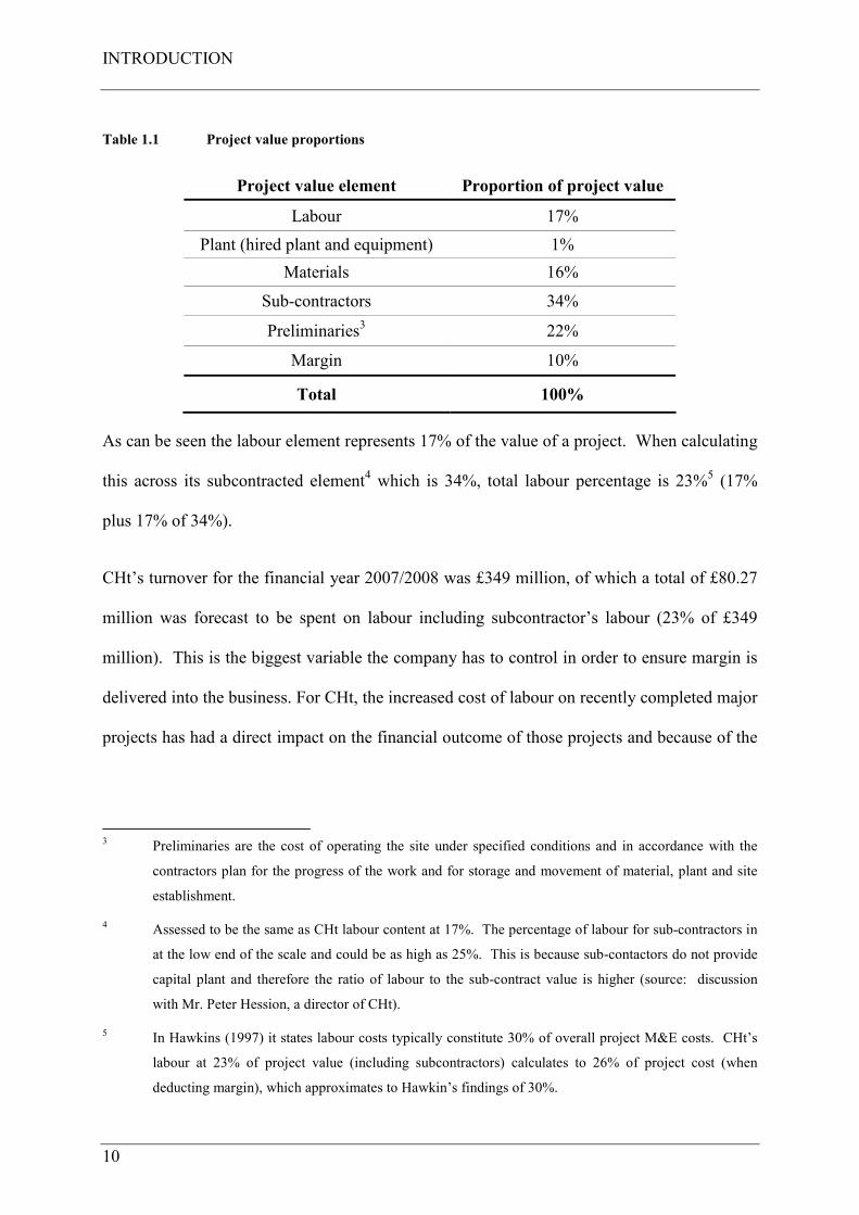
Table 1.1 Project value proportions
Project value element Proportion of project value
Labour 17%
Plant (hired plant and equipment) 1%
Materials 16%
Sub-contractors 34%
Preliminaries3 22%
Margin 10%
Total 100%
As can be seen the labour element represents 17% of the value of a project. When calculating
this across its subcontracted element4 which is 34%, total labour percentage is 23%
5 (17%
plus 17% of 34%).
CHt’s turnover for the financial year 2007/2008 was £349 million, of which a total of £80.27
million was forecast to be spent on labour including subcontractor’s labour (23% of £349
million). This is the biggest variable the company has to control in order to ensure margin is
delivered into the business. For CHt, the increased cost of labour on recently completed major
projects has had a direct impact on the financial outcome of those projects and because of the
3 Preliminaries are the cost of operating the site under specified conditions and in accordance with the
contractors plan for the progress of the work and for storage and movement of material, plant and site
establishment.
4 Assessed to be the same as CHt labour content at 17%. The percentage of labour for sub-contractors in
at the low end of the scale and could be as high as 25%. This is because sub-contactors do not provide
capital plant and therefore the ratio of labour to the sub-contract value is higher (source: discussion
with Mr. Peter Hession, a director of CHt).
5 In Hawkins (1997) it states labour costs typically constitute 30% of overall project M&E costs. CHt’s
labour at 23% of project value (including subcontractors) calculates to 26% of project cost (when
deducting margin), which approximates to Hawkin’s findings of 30%.

INTRODUCTION
11
scale of the cost overruns, CHt itself (Court et al. 2005). These projects were run in a
traditional manner with no specific Lean interventions being made.
CHt also wants to improve its health and safety performance across the business. They are
not immune from the construction environment in which they operate and indeed suffer in the
same way as the wider M&E industry. Whilst CHt’s safety records have deserved and indeed
won safety awards and it is profitable, there is always room for improvement. One accident is
one too many and profit improvement is always resonant in the board room. Therefore, CHt
sees this research project as another means to improve health and safety for its workers and to
ensure that everyone goes home safely at the end of a productive days work, especially as the
research project specifically seeks to improve workers health, safety and productivity as will
be shown.
This research project therefore proposes that Lean techniques, when imposed upon a project,
are an antidote to the health, safety and productivity problems that CHt faces in the M&E
industry, within the UK construction sector.
As a point to note, the author is the M&E Project Leader for CHt on the case study project
and is submitting this thesis as part of the award for the Engineering Doctorate.
1.5 STRUCTURE OF THIS THESIS
The structure of the thesis is presented below informing the reader of the content of each
chapter of the thesis.
Chapter one introduces the general subject domain, the industrial sponsor and the context of
the research.
Chapter two presents the overarching aims and objectives of the research.
INTRODUCTION
12
Chapter three discusses the methodological considerations, methodology development and
refinement and the methods and tools used for the research undertaken.
Chapter four describes the main steps of the research undertaken and presents the results of
the implementation of the Construction System on a case study project.
Chapter five discusses the key findings of the research, the contribution to existing theory and
practice, the implications and impact on the sponsor company and on the wider industry. It
concludes with recommendations for industry and further research with a critical evaluation
of the research undertaken.
Appendix A-E presents the five academic papers published during this research. These
papers are an essential part of the research and should be read in conjunction with this thesis.
Appendix F-H contains the BSRIA best practice recommendations which this research project
takes particular cognisance of, the safety results during the sample period and certain
important lessons learned from the implementation of the Construction System.
1.6 SYNOPSIS OF PAPERS
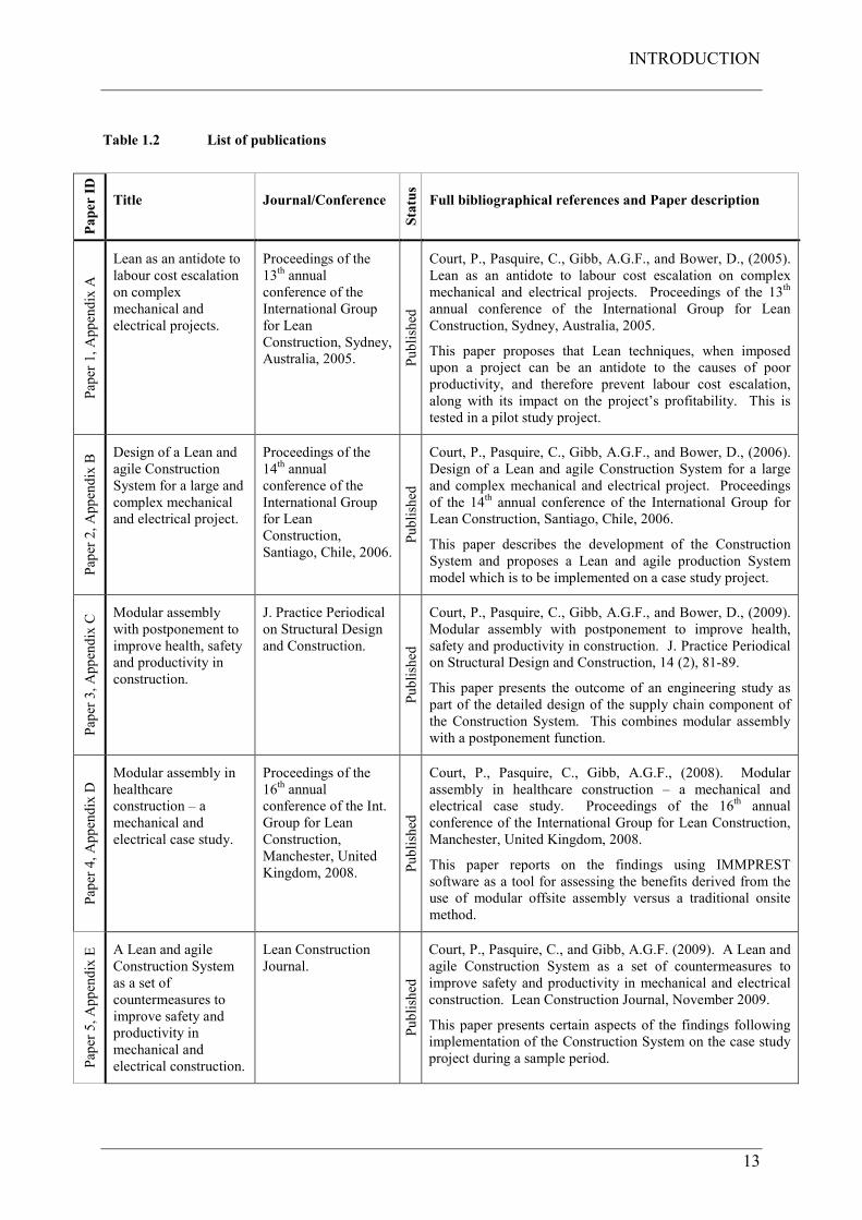
To summarise and disseminate the research findings of this project, five scientific papers have
been published during the period and these are presented in table 1.2. Full bibliographical
references are provided, together with the status of each paper, and a brief description of their
contribution to the fulfilment of the research aim and objectives. Each paper has been
indentified by a paper number and the corresponding appendix reference.
INTRODUCTION
13
Table 1.2 List of publications
Paper ID
Title Journal/Conference
Status
Full bibliographical references and Paper description
Paper 1, Appendix A
Lean as an antidote to
labour cost escalation
on complex
mechanical and
electrical projects.
Proceedings of the
13th annual
conference of the
International Group
for Lean
Construction, Sydney,
Australia, 2005. Published
Court, P., Pasquire, C., Gibb, A.G.F., and Bower, D., (2005).
Lean as an antidote to labour cost escalation on complex
mechanical and electrical projects. Proceedings of the 13th
annual conference of the International Group for Lean
Construction, Sydney, Australia, 2005.
This paper proposes that Lean techniques, when imposed
upon a project can be an antidote to the causes of poor
productivity, and therefore prevent labour cost escalation,
along with its impact on the project’s profitability. This is
tested in a pilot study project.
Paper 2, Appendix B Design of a Lean and
agile Construction
System for a large and
complex mechanical
and electrical project.
Proceedings of the
14th annual
conference of the
International Group
for Lean
Construction,
Santiago, Chile, 2006.
Published
Court, P., Pasquire, C., Gibb, A.G.F., and Bower, D., (2006).
Design of a Lean and agile Construction System for a large
and complex mechanical and electrical project. Proceedings
of the 14th annual conference of the International Group for
Lean Construction, Santiago, Chile, 2006.
This paper describes the development of the Construction
System and proposes a Lean and agile production System
model which is to be implemented on a case study project.
Paper 3, Appendix C Modular assembly
with postponement to
improve health, safety
and productivity in
construction.
J. Practice Periodical
on Structural Design
and Construction.
Published
Court, P., Pasquire, C., Gibb, A.G.F., and Bower, D., (2009).
Modular assembly with postponement to improve health,
safety and productivity in construction. J. Practice Periodical
on Structural Design and Construction, 14 (2), 81-89.
This paper presents the outcome of an engineering study as
part of the detailed design of the supply chain component of
the Construction System. This combines modular assembly
with a postponement function.
Paper 4, Appendix D Modular assembly in
healthcare
construction – a
mechanical and
electrical case study.
Proceedings of the
16th annual
conference of the Int.
Group for Lean
Construction,
Manchester, United
Kingdom, 2008. Published
Court, P., Pasquire, C., Gibb, A.G.F., (2008). Modular
assembly in healthcare construction – a mechanical and
electrical case study. Proceedings of the 16th annual
conference of the International Group for Lean Construction,
Manchester, United Kingdom, 2008.
This paper reports on the findings using IMMPREST
software as a tool for assessing the benefits derived from the
use of modular offsite assembly versus a traditional onsite
method.
Paper 5, Appendix E
A Lean and agile
Construction System
as a set of
countermeasures to
improve safety and
productivity in
mechanical and
electrical construction.
Lean Construction
Journal.
Published
Court, P., Pasquire, C., and Gibb, A.G.F. (2009). A Lean and
agile Construction System as a set of countermeasures to
improve safety and productivity in mechanical and electrical
construction. Lean Construction Journal, November 2009.
This paper presents certain aspects of the findings following
implementation of the Construction System on the case study
project during a sample period.
INTRODUCTION
14
1.7 CHAPTER SUMMARY
This chapter has set out the background to the research conducted and has introduced the
general subject domain which is Lean Thinking and Lean Construction. It has introduced the
industrial sponsor, CHt, together with the context of the research for them. Finally, the
structure of this thesis has been described with a synopsis of each of the published papers
contained in appendix A-E of this thesis.
OVERARCHING AIM AND OBJECTIVES
15
CHAPTER 2 OVERARCHING AIM AND OBJECTIVES
2.1 INTRODUCTION
This chapter sets out the aim and objectives of the research undertaken together with the
development of the research aim which has occurred since this project commenced.
2.2 OVERARCHING AIM
The overarching aim of this research project is to develop and implement a new way of
working for CHt in order to improve the performance of its projects site operations, making
them safer for the worker and to improve productivity as a countermeasure to the problems
that CHt faces in the M&E industry within the UK construction sector.
Safety is at the core of the company and according to the Business Leaders “…it is an
absolute right for people to return home safely at the end of a productive day’s work” and
“failure to do so render the company valueless.” The key words here being safely and
productive, these are therefore at the core of the aim of this research project which is to design
and implement a safer and more productive way of working on site (i.e., the
countermeasures6). It takes a holistic approach to develop and implement a Lean and agile
Construction System to transform traditional M&E construction into a modern process of
assembly to the benefit of the worker, the company and the industry. Further than this, CHt
see this research project as a vehicle not only to deliver performance improvement but, when
embedded and repeated across all of its projects, for it to become a source of competitive
6 A countermeasure is defined by Oxford English Dictionary (2009) as an action taken to counteract a
danger or threat. The threat to the company is the primary issues faced in UK construction, i.e. the
research problem.
OVERARCHING AIM AND OBJECTIVES
16
advantage which will provide a stable flow of profitable safe projects leading to an increase in
the company’s enterprise value7.
Quality is an important aspect of the work that CHt carries out and is inextricably linked to
the performance of its projects as is health, safety, productivity and cost. That said it is not
the intent to measure quality outcomes as a result of implementing the System described in
this thesis as the case study project is subject to the ISO 9001 quality systems and procedures
that CHt are accredited to and are audited against. The case study project has a quality system
in place which is audited by a third party organisation as part of CHt’s ongoing annual
accreditation process. The outcomes of this quality system and the actual audits are not
reported in this thesis.
2.3 DEVELOPMENT OF THE RESEARCH AIM
Initiated in 2003, the initial intent of the research was to develop ways to reduce the costs of
delivering projects for the sponsor company who were at that time owned by the construction
company, Carillion PLC. It was thought then that by improving productivity on its
construction sites, CHt could have some control over the largest cost variable that can
influence the financial outcome of its projects, which is labour cost. If labour cost escalates
above that which is estimated for the project then margin slippage can occur. This is because
productivity of labour has a direct influence on labour cost and therefore the projects financial
outcome as was discovered in the initial stages of the research. In these initial stages of the
research looking into the factors that influence productivity it became evident that these
factors also had an effect on the health and safety of workers, so by overcoming these factors
then the health and safety of CHt’s workers could also be improved together with
7 Enterprise value is defined as a company’s worth as a functioning entity, or its acquisition cost.
OVERARCHING AIM AND OBJECTIVES
17
productivity. This was coincidental with a change of ownership of CHt from Carillion to
LOR in 2004. With this came LOR’s purpose and vision statements and the Incident and
Injury Free (IIF) programme, the objective of which is to send everyone home safely after a
productive days work. This is not to say that CHt or Carillion were not interested in health
and Safety at that time, far from it, but it coincidentally joined productivity with health and
safety improvements as an aim for this research project as they are so inextricably linked
together and this matched the requirements of LOR’s IIF programme.
2.4 RESEARCH OBJECTIVES
The overall objective was to identify the issues that cause poor productivity and health and
safety performance in M&E construction and to develop a conceptual system using Lean
methods from other industries that can overcome these issues. Following this, to then develop
the conceptual Construction System into real and meaningful methods that are able to be
applied and tested on a case study project during a sample period. This was to be achieved
with the following six research objectives:
Objective 1: To reveal and understand the issues that leads to poor health, safety and
productivity performance;
Objective 2: To reveal and understand Lean methods in use in other industries;
Objective 3: To develop a conceptual Construction System that adopts Lean methods from
other industries that can be applied to M&E construction;
Objective 4: To turn the theory of the developed System into practice with real and practical
methods that is able to be applied to a case study project in the real world;
Objective 5: To set realistic and achievable targets against which the System can be
measured during implementation;
OVERARCHING AIM AND OBJECTIVES
18
Objective 6: To implement the System on a live case study project and to measure the
results emerging during the implementation.
2.5 CHAPTER SUMMARY
This research project has the overarching aim to develop and implement a new way of
working for CHt in order to improve the performance of its projects site operations, making
them safer for the worker and to improve productivity. It seeks to challenge and change
traditional construction thinking and to develop and implement a system to transform
traditional M&E construction into a modern process of assembly. This system will be called
the “Crown House Construction System.” The Construction System is defined as a pre-
assembly methodology that will demonstrate the feasibility of creating and implementing new
processes in M&E construction. The transformation expected is the creation of a step-change
in undertaking M&E construction work and to realise significant improvements in
performance. It will industrialise8 traditional M&E construction using Lean and agile
manufacturing techniques making the work safer, more effective and productive.
8 Industrialisation is the development of an industry on an extensive scale (Visual Thesaurus 2009).
ADOPTED METHODOLOGY
19
CHAPTER 3 ADOPTED METHODOLOGY
3.1 INTRODUCTION
The success and validity of any research critically depends upon the appropriate selection of
research methods (Fellows and Liu 2003). This chapter sets out the research methodological
considerations, the research methodology development and refinement, the methods and tools
used and the role of these methods within the research methodology chosen and the
development of the research process undertaken.
3.2 METHODOLOGICAL CONSIDERATIONS
As has been described, the overarching aim of this research project for CHt was to develop
and implement a new way of working in order to improve its site operations, making them
safer for the worker and to improve productivity as a countermeasure to the prevailing
conditions in UK construction that CHt faces. The problems that cause poor health, safety
and productivity performance exist on the construction site where the work is performed by
CHt’s workforce and that of its and other interfacing sub-contractors. These were to be
overcome with specifically designed countermeasures as an antidote to these problems that
exist. The construction site was therefore a main focus of attention for this research project.
According to The Productivity Press Development Team (2002), when solving productivity
problems it is essential that you actually go to the work site and closely examine the operation
or process being improved so that you do not make incorrect assumptions about the actual
causes which will lead you to solve the wrong problem, fail to find the root cause and
therefore have a return of the problem later or miss the real issues in some other way. Also,
and significantly in the world of Lean according to Ohno (1988), the production plant is
ADOPTED METHODOLOGY
20
manufacturing’s major source of information, it provides the most direct, current and
stimulating information about management, this is what Ohno called his plant-first principle.
Liker (2004), describing The Toyota Way 14 Management Principles, describes principle 12
which is to go and see for yourself to be able to thoroughly understand the situation. The key
points of this principle are described as follows:
• Solve problems and improve processes by going to the source and personally observing
and verifying data rather than theorising on the basis of what other people or the
computer screen tell you;
• Think and speak based on personally verified data;
• Even high-level managers and executives should go and see things for themselves so
they will have more than a superficial understanding of the situation.
This research project did not seek to measure specific task productivity performance of the
M&E activities undertaken by CHt; enough of this has been done already (Hawkins 1997).
The author decided that there was no value in repeating the research Hawkins had already
undertaken as CHt was a sponsor in this study and contributed to the research at that time.
Rather the choice was to accept its findings and to take cognisance of the best practice
recommendations made as a basis for this research project. With this in mind and using
Ohno’s plant-first principle, combined with the problem-solving method from the
Productivity Press and Toyotas principle 12, a site-first principle9 was used. The site is to
construction in the same way as the plant is to manufacturing. As Ohno describes his plant-
first principle as being manufacturing’s major source of information, this is the same for the
construction site. It is the culmination of all the construction processes and what is given to
the customer (or end-user) when it is finished. Also, are workers the only participants in the
9 Named by the author for this combination of methods.
ADOPTED METHODOLOGY
21
building process directly generating value to the customer? Larsen et al. (2003) argued this
point and these were the reasons for the principle method of this research project which
sought to focus on the worker and the worker’s environment. It was only concerned with
M&E workers and those of key interfacing trades insofar as they apply. This research could
only be done on the construction site itself by personal observation, verification and to think
and speak on this personally verified data.
3.3 METHODOLOGY DEVELOPMENT / REFINEMENT
3.3.1 The research process
In the 1980’s The Science and Engineering Research Council (SERC), the forerunner of the
Engineering and Physical Sciences Research Council (EPSRC) in the UK, held a Specially
Promoted Programme (SPP) in Construction Management and developed their view of the
research process relating to the SPP (Fellows and Liu 2003). Also, when considering
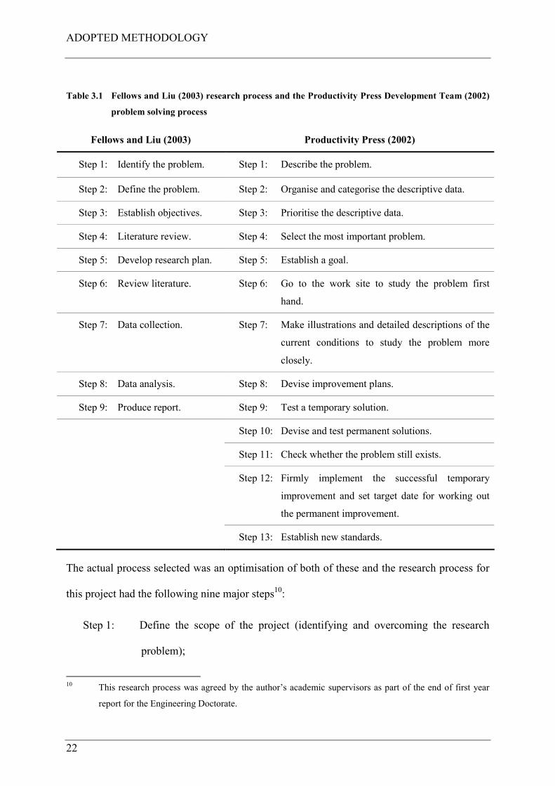
standardisation, the Productivity Press Development Team (2002) describes a complete
sequence for solving problems. The major steps in each of these processes are shown in table
3.1.
ADOPTED METHODOLOGY
22
Table 3.1 Fellows and Liu (2003) research process and the Productivity Press Development Team (2002)
problem solving process
Fellows and Liu (2003) Productivity Press (2002)
Step 1: Identify the problem. Step 1: Describe the problem.
Step 2: Define the problem. Step 2: Organise and categorise the descriptive data.
Step 3: Establish objectives. Step 3: Prioritise the descriptive data.
Step 4: Literature review. Step 4: Select the most important problem.
Step 5: Develop research plan. Step 5: Establish a goal.
Step 6: Review literature. Step 6: Go to the work site to study the problem first
hand.
Step 7: Data collection. Step 7: Make illustrations and detailed descriptions of the
current conditions to study the problem more
closely.
Step 8: Data analysis. Step 8: Devise improvement plans.
Step 9: Produce report. Step 9: Test a temporary solution.
Step 10: Devise and test permanent solutions.
Step 11: Check whether the problem still exists.
Step 12: Firmly implement the successful temporary
improvement and set target date for working out
the permanent improvement.
Step 13: Establish new standards.
The actual process selected was an optimisation of both of these and the research process for
this project had the following nine major steps10:
Step 1: Define the scope of the project (identifying and overcoming the research
problem);
10 This research process was agreed by the author’s academic supervisors as part of the end of first year
report for the Engineering Doctorate.
ADOPTED METHODOLOGY
23
Step 2: Data collection for the current state (the situation today) including
observation of current practice with action research and a literature search for
further evidence of the current state;
Step 3: Data collection for the future state (the vision of how things could be)
including literature search for the future vision, looking outside the industry
for best practice and innovation and inside the industry for best practice and
innovation. This will include more than a literature search and will include
action research inside other industries;
Step 4: Breakthrough thinking for development of options for analysis;
Step 5: Analysis and experimentation of options for implementation;
Step 6: Setting of realistic objectives and measurement of success for implementation
(how will we know it’s working when we have done it);
Step 7: Actual implementation and testing solutions;
Step 8: First run study with results emerging;
Step 9: Production of a thesis for this Engineering Doctorate.
The research methods and tools used to conduct this research project are now described.
3.4 METHODS / TOOLS USED
The principle methods used within this research process were action research; literature
search; observational study; ethnography and experimental study.
3.4.1 Action research
Coghlan and Brannick (2003) define action research as involving a cyclical process of
diagnosing a change situation or problem, gathering data, taking action, and then fact finding
about the results of that action in order to plan and take further action. Also, the key idea of
ADOPTED METHODOLOGY
24
action research is that it uses a scientific approach to study the resolution of important social
and organisational issues together with those who experience these issues directly. Action
research spanned all of the steps in this research project in order to diagnose the research
problem, gather data, take action and fact find results to allow further action to be taken.
3.4.2 Literature search
According to Fellows and Liu (2003), an essential early stage of virtually all research is to
search for and to examine potentially relevant theory and literature. Theory and literature are
the results of previous research projects. They define theory as the established principles and
laws which have been found to hold, whereas in this context they define literature as
concerning the findings from research which has not attained the status of theory. As Fellows
and Liu state, it often represents findings from research into particular applications of theory.
A literature search has been used in this research project to allow the author to understand
past and current theory and practice required related to the context of this study. This
research method also spanned all of the steps in the research project to enable the author to
keep up to date with potentially relevant theory and literature.
3.4.3 Observational study
According to Yin (2003), observational evidence is often useful in providing additional
information about the topic being studied. If a case study is about a new technology then
observations of the technology at work are invaluable aids for understanding the actual uses
of the technology or the problems encountered. Also, the condition of buildings or work
spaces will indicate something about the climate or impoverishment of the organisation (Yin
2003). Observational studies have been used in this research project which allowed the author
to go to the source and personally verify data (Liker 2004), and to provide direct information
ADOPTED METHODOLOGY
25
and feedback on current practice on construction sites and inside other industries related to
this project.
3.4.4 Ethnography
In order to be able to think and speak on personally verified data (Liker 2004), an
ethnographic study method was also used. Ethnography is a style of research rather than a
single method and uses a variety of techniques to collect data (Cassell and Symon 2004).
They defined this style of research as the study of people in naturally occurring settings or
‘fields’ by means of methods which capture their social meanings and ordinary activities,
involving the researcher participating directly in the setting (if not also in the activities) in
order to collect data in a systematic manner but without meaning being imposed on them
externally. The purpose of this study was for the author to become a participant in the site
process in order to be immersed in the day-to-day site activities and not just be an observer.
This method allowed the author to understand people’s actions and their experiences of the
world in natural settings as they occurred independently of experimental manipulation11.
3.4.5 Experimental study
An experimental study was the chosen method to test the Construction System on the case
study12 project. According to Yin (2003), experiments are done when an investigator can
manipulate behaviour directly, precisely and systematically. This can occur in a laboratory
setting and in this context the North Staffordshire Hospitals Project (the case study project)
11 Where deliberate intervention is made by the researcher/s which may affect the outcome of the study
being undertaken.
12 The term case study is used in this thesis to describe the project where the Construction System will be
tested, not the research method itself. It is accepted that the term “case study” is a recognised research
method but where no control over behavioural events is required (Yin 2003).
ADOPTED METHODOLOGY
26
was the large real-life laboratory where the author manipulated behaviour directly, precisely
and systematically by imposing the Construction System as a set of countermeasures to what
would otherwise have occurred naturally. A small scale experimental study was also used in
the early stages of the research project to test Lean interventions in a pilot study. The
experimental studies undertaken in this research project used the concepts of hypothesis;
independent variables; dependent variables and measurement (Smith et al. 2003). How these
concepts relate to the experimental study undertaken were described in Court et al. 2005
(paper 1 contained in appendix A), and in chapter 4 of this thesis.
3.4.6 Research development process
Having described the aim and objectives of the research project in the last chapter, and the
methodology and methods used to achieve the objectives, figure 3.1 presents a map of the
research development process connecting the research objectives with the steps in the
research process, the research methods used and then to the EngD deliverables which are the
five published papers and this thesis.
3.5 CHAPTER SUMMARY
This chapter has described the research methodological considerations, its development and
refinement and the research methods used. A map of the research development process has
been presented which sets out the six research objectives, their connection to each step in the
research process, the research methods used and their role in the process, and finally the
findings from the steps in the process that were then published as scientific papers in refereed
journals and conferences (see Appendix A-E). The next phase is the actual research
undertaken and this is described in the next chapter.
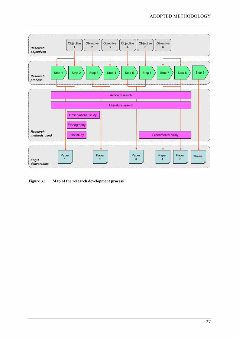
ADOPTED METHODOLOGY
27
Research
process
Research
process
Research
objectives
Research
objectives
Paper
1
Paper
2
Paper
3Paper
4
Paper
5ThesisPaper
1
Paper
1
Paper
2
Paper
2
Paper
3
Paper
3Paper
4
Paper
4
Paper
5
Paper
5ThesisThesis
Step 1 Step 2 Step 3 Step 4 Step 5 Step 6 Step 7 Step 8 Step 9Step 1Step 1 Step 2Step 2 Step 3Step 3 Step 4Step 4 Step 5Step 5 Step 6Step 6 Step 7Step 7 Step 8Step 8 Step 9Step 9
Objective
1
Objective
2
Objective
3
Objective
4
Objective
5
Objective
6
Objective
1
Objective
1
Objective
2
Objective
2
Objective
3
Objective
3
Objective
4
Objective
4
Objective
5
Objective
5
Objective
6
Objective
6
Observational study
Ethnography
EngD
deliverables
Research
methods used Experimental study
Action research
Pilot study
Literature search
Figure 3.1 Map of the research development process

ADOPTED METHODOLOGY
28
THE RESEARCH UNDERTAKEN
29
CHAPTER 4 THE RESEARCH UNDERTAKEN
4.1 INTRODUCTION
The research undertaken followed the process and steps described in chapter 3, Adopted
Methodology and these steps were:
Step 1: Define the scope of the project (identifying and overcoming the research
problem);
Step 2: Data collection for the current state (the situation today);
Step 3: Data collection for the future state (the vision of how things could be);
Step 4: Breakthrough thinking for development of options for analysis;
Step 5: Analysis and experimentation of options for implementation;
Step 6: Setting of realistic objectives and measurement of success for implementation;
Step 7: Actual implementation and testing solutions;
Step 8: First run study with results emerging;
Step 9: Production of a thesis for this Engineering Doctorate.
This chapter describes the research undertaken in each of these steps.
4.2 STEP 1: DEFINE THE SCOPE OF THE PROJECT
The scope (also the aim) of this research project was to develop a way of working on site that
will overcome the issues of poor productivity and safety performance (the research problem)
that the construction industry and in particular the M&E work which CHt undertakes. This
has been termed “Transforming Traditional Mechanical and Electrical Construction into a
Modern Process of Assembly” created by the development of the “Crown House Construction
System.” This title was inspired by the “Toyota Production System” but the research did not
THE RESEARCH UNDERTAKEN
30
seek to replicate the Toyota Production System itself. Once developed this Construction
System was tested on a live case study project, the selection of which is described later in this
thesis.
4.3 STEP 2: DATA COLLECTION FOR THE CURRENT STATE
Step 2 of the research process involved collecting data to identify the current state (the
situation today). This step commenced the action research method, and included a literature
search, observational studies, ethnography and a pilot experimental study.
4.3.1 Literature search
The findings of the literature search supported the development of the Construction System
by revealing the issues that created the research problem. The primary issues identified
concerned health and safety; space (congestion onsite); relationships between crews that
caused interference or delay; productivity; worker availability and skills.
4.3.1.1 Health and Safety issues
According to the Health and Safety Executive (HSE) 2007, 2.2 million people work in
Britain’s construction industry making it the countries biggest industry, it is also one of the
most dangerous. In the last 25 years over 2,800 people have died from injuries they received
as a result of construction work, many more have been injured or made ill. The HSE (2007a)
identified that construction also has the highest rate of musculoskeletal disorders (MSD’s);
these are mostly back injuries from manual handling. There were 56,000 work related MSD
cases in construction in 2004/5. Handling injuries (to employees in 2004/5) accounted for
38% of over 3 day injuries and 15% of major injuries. In their research into MSD’s, the HSE
(2007b) has identified areas that can create a risk which includes; repetitive and heavy lifting;
THE RESEARCH UNDERTAKEN
31
bending and twisting; repeating an action too frequently; uncomfortable working position;
exerting too much force; working too long without breaks; adverse working environment (e.g.
hot, cold); psychosocial factors (e.g. high job demands, time pressures and lack of control);
not receiving and acting upon reports of symptoms quickly enough.
Considering other health and safety factors, occupational health has been ignored in favour of
the more immediate, high impact occupational safety (Gibb 2006). Gibb argues that
occupational health incidents are to be considered as “slow accidents” – the period over which
the incident occurs may be lengthy and may creep up on you unawares. This implies that the
result will be the same as an occupational accident; in that a worker gets injured but it just
takes longer. Gibb’s keynote paper reports that in the UK 4,500 construction workers are
absent from work every day because of injuries caused by accidents, but there are 11,000
construction workers off sick at any one time with a work-related illness. Gibb reports that in
the UK, the construction industry employs around 10% of the working population but causes
a much greater percentage of occupational ill health. Furthermore, it is reported by Gibb,
MSD’s which, according to the limited evidence available, may be the most widespread
problem in the industry.
Research conducted for its Better Backs Campaign (HSE 2000) found that a change to
prefabricated modules for mechanical and electrical works, and the use of mechanical aids to
lift them, significantly reduced the risk of manual handling injury. This enabled employees to
maintain an improved posture when connecting and testing the units. Other benefits were
found in the study including a considerable saving in time, no storage space required, no full
floor scaffold required and improved consistency and quality of work.
THE RESEARCH UNDERTAKEN
32
4.3.1.2 Space issues
The availability of space on construction sites has a direct influence on workers safety and
productivity. According to Winch and North (2006), it is known that congestion on site
reduces output and generates hazards. Akinci et al. (2002) report that construction activities
require a set of work spaces to be executed safely and productively. Akinci et al. (2002a) also
find that to provide a safe and productive environment, managers need to plan for the work
required by construction activities. Guo (2002) reported that a crowded jobsite is a major
cause of productivity decrease and schedule interference or delay. Guo found that numerous
workers, equipment, material, temporary facilities and permanent structures share limited
space during construction. Space constraints thus affect the moving path and productivity, it
is essential therefore to organise the available space efficiently in order to minimise space
conflicts.
4.3.1.3 Crew relationship issues
M&E installations are complex (defined by the number of components or activities that
interact), comprising many actions and activities by different trades or subcycles to be
completed successfully (i.e. ductwork, pipework, electrical systems, data systems, with
building fabric systems such as partitioning and ceilings etc.). Howell et al. (1993) describe
that productivity suffers when the output of one subcycle delays a following step or when
resources required for one subcycle are engaged in another subcycle. Thomas et al. (2004)
report that symbiotic crew relationships occur when the pace of a crew depends on the pace of
a preceding crew; that sometimes these relationships are loose and relatively independent and
at other times these relationships are tight and closely dependant. The research found that it is
more common to have tight relationships in mechanical, electrical, plumbing and finishing
THE RESEARCH UNDERTAKEN
33
trades. It defines this tight and dependant relationship as symbiotic. It found that the
performance of crews with symbiotic relationships is shown to be consistently worse than
when these relationships are not present. A method to avoid symbiotic relationships is
recommended by simplifying the operations using preassemblies. This reduces the amount of
work on site by fabricating and assembling M&E modules offsite and simply installing these
with a small installation team. Horman et al. (2006) reported on factors that bear significantly
on the performance of electrical contractors in building construction projects. It found that
when project work sequences are poorly planned, or poorly executed, electrical constructors
often must contend with compressed schedules, trade stacking and out of sequence work.
4.3.1.4 Productivity issues
According to Hawkins (1997) labour costs typically constitute 30% of the overall project
M&E costs, so maximising the output on site is essential to increase a contractor’s
performance and the value for money investment of the customer. This statement was part of
a report of an investigative study undertaken by the Building Services Research and
Information Association (BSRIA), and sets a foundation for understanding the problems and
issues that the UK M&E industry faces within the construction sector. BSRIA undertook this
investigative study comparing four UK, one American, one German and one Swedish
construction projects to highlight productivity problems relating to M&E building services, to
assist the UK M&E industry in promoting improvements in productivity, and to suggest
remedies to solve these problems and improve performance. The study focussed upon
activities specific to the onsite works, the aim of which was to divide output into its
productive and non-productive components and then to develop best practice guidelines
relating to input that would maximise the productive time and subsequent productivity
achieved at the workplace. Significantly the UK projects monitored, had an average overall
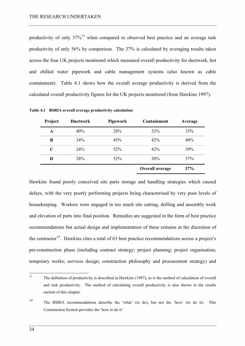
THE RESEARCH UNDERTAKEN
34
productivity of only 37%13 when compared to observed best practice and an average task
productivity of only 56% by comparison. The 37% is calculated by averaging results taken
across the four UK projects monitored which measured overall productivity for ductwork, hot
and chilled water pipework and cable management systems (also known as cable
containment). Table 4.1 shows how the overall average productivity is derived from the
calculated overall productivity figures for the UK projects monitored (from Hawkins 1997).
Table 4.1 BSRIA overall average productivity calculation
Project Ductwork Pipework Containment Average
A 40% 28% 32% 33%
B 34% 45% 42% 40%
C 24% 52% 42% 39%
D 28% 52% 30% 37%
Overall average 37%
Hawkins found poorly conceived site parts storage and handling strategies which caused
delays, with the very poorly performing projects being characterised by very poor levels of
housekeeping. Workers were engaged in too much site cutting, drilling and assembly work
and elevation of parts into final position. Remedies are suggested in the form of best practice
recommendations but actual design and implementation of these remains at the discretion of
the contractor14. Hawkins cites a total of 63 best practice recommendations across a project’s
pre-construction phase (including contract strategy; project planning; project organisation;
temporary works; services design; construction philosophy and procurement strategy) and
13 The definition of productivity is described in Hawkins (1997), as is the method of calculation of overall
and task productivity. The method of calculating overall productivity is also shown in the results
section of this chapter.
14 The BSRIA recommendations describe the ‘what’ (to do), but not the ‘how’ (to do it). This
Construction System provides the ‘how to do it’.
THE RESEARCH UNDERTAKEN
35
construction phase (including work arrangement; work area control and installation). As
described, this research project takes particular cognisance of these recommendations which
are shown in appendix F of this thesis together with a statement of whether or not each of
these are already implemented within CHt or if they have been implemented as part of the
Construction System.
The report, “Innovative M&E Installation” by Wilson (2000), follows on from Hawkins
(1997) and recommends that alternative systems, components, materials and innovative
methods should be thoroughly evaluated to identify opportunities for productivity gains on
M&E projects. It concludes that the UK (M&E) construction industry must replace outdated
components and processes if it is to remain competitive in a global marketplace. This
research found that the UK construction industry can realise a significant gain in installation
performance through the adoption of innovative components and systems. Subsequent
research conducted by BSRIA (Hawkins 2002) concluded that UK construction project teams
that implemented improvement strategies and actions, in accordance with the BSRIA best
practice recommendations, have realised significant improvements in site productivity. The
research found the teams that designed for high site productivity, used innovative components
and exploited offsite manufacture, realised a step-change improvement in construction site
productivity rates. It also found that whilst the use of innovative products and offsite
manufacturing techniques can deliver a huge improvement in project performance, their true
value was still not being fully exploited.
It is the opinion of the author that the condition of productivity in UK M&E construction is by
and large as Hawkins reported in 1997. Moreover, companies that do implement best practice
do see improvement in productivity rates as Hawkins (2002) further reports. This is
evidenced by the observations and research undertaken by the author during the course of this
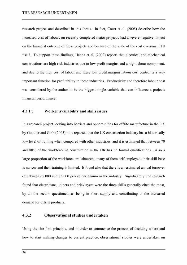
THE RESEARCH UNDERTAKEN
36
research project and described in this thesis. In fact, Court et al. (2005) describe how the
increased cost of labour, on recently completed major projects, had a severe negative impact
on the financial outcome of those projects and because of the scale of the cost overruns, CHt
itself. To support these findings, Hanna et al. (2002) reports that electrical and mechanical
constructions are high-risk industries due to low profit margins and a high labour component,
and due to the high cost of labour and these low profit margins labour cost control is a very
important function for profitability in these industries. Productivity and therefore labour cost
was considered by the author to be the biggest single variable that can influence a projects
financial performance.
4.3.1.5 Worker availability and skills issues
In a research project looking into barriers and opportunities for offsite manufacture in the UK
by Goodier and Gibb (2005), it is reported that the UK construction industry has a historically
low level of training when compared with other industries, and it is estimated that between 70
and 80% of the workforce in construction in the UK has no formal qualifications. Also a
large proportion of the workforce are labourers, many of them self-employed, their skill base
is narrow and their training is limited. It found also that there is an estimated annual turnover
of between 65,000 and 75,000 people per annum in the industry. Significantly, the research
found that electricians, joiners and bricklayers were the three skills generally cited the most,
by all the sectors questioned, as being in short supply and contributing to the increased
demand for offsite products.
4.3.2 Observational studies undertaken
Using the site first principle, and in order to commence the process of deciding where and
how to start making changes to current practice, observational studies were undertaken on
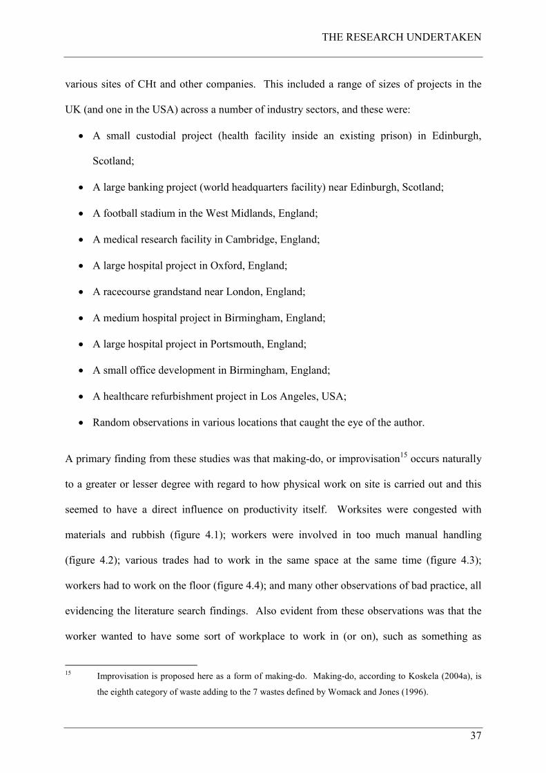
THE RESEARCH UNDERTAKEN
37
various sites of CHt and other companies. This included a range of sizes of projects in the
UK (and one in the USA) across a number of industry sectors, and these were:
• A small custodial project (health facility inside an existing prison) in Edinburgh,
Scotland;
• A large banking project (world headquarters facility) near Edinburgh, Scotland;
• A football stadium in the West Midlands, England;
• A medical research facility in Cambridge, England;
• A large hospital project in Oxford, England;
• A racecourse grandstand near London, England;
• A medium hospital project in Birmingham, England;
• A large hospital project in Portsmouth, England;
• A small office development in Birmingham, England;
• A healthcare refurbishment project in Los Angeles, USA;
• Random observations in various locations that caught the eye of the author.
A primary finding from these studies was that making-do, or improvisation15 occurs naturally
to a greater or lesser degree with regard to how physical work on site is carried out and this
seemed to have a direct influence on productivity itself. Worksites were congested with
materials and rubbish (figure 4.1); workers were involved in too much manual handling
(figure 4.2); various trades had to work in the same space at the same time (figure 4.3);
workers had to work on the floor (figure 4.4); and many other observations of bad practice, all
evidencing the literature search findings. Also evident from these observations was that the
worker wanted to have some sort of workplace to work in (or on), such as something as
15 Improvisation is proposed here as a form of making-do. Making-do, according to Koskela (2004a), is
the eighth category of waste adding to the 7 wastes defined by Womack and Jones (1996).
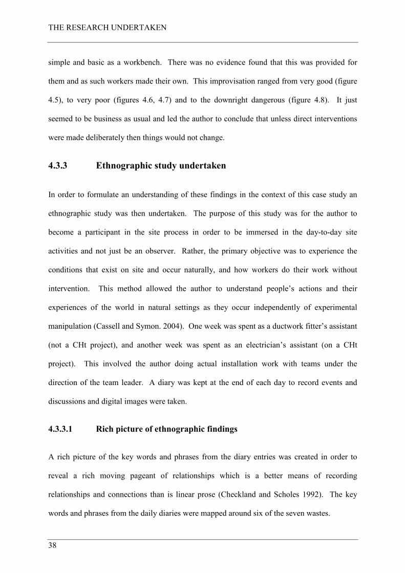
THE RESEARCH UNDERTAKEN
38
simple and basic as a workbench. There was no evidence found that this was provided for
them and as such workers made their own. This improvisation ranged from very good (figure
4.5), to very poor (figures 4.6, 4.7) and to the downright dangerous (figure 4.8). It just
seemed to be business as usual and led the author to conclude that unless direct interventions
were made deliberately then things would not change.
4.3.3 Ethnographic study undertaken
In order to formulate an understanding of these findings in the context of this case study an
ethnographic study was then undertaken. The purpose of this study was for the author to
become a participant in the site process in order to be immersed in the day-to-day site
activities and not just be an observer. Rather, the primary objective was to experience the
conditions that exist on site and occur naturally, and how workers do their work without
intervention. This method allowed the author to understand people’s actions and their
experiences of the world in natural settings as they occur independently of experimental
manipulation (Cassell and Symon. 2004). One week was spent as a ductwork fitter’s assistant
(not a CHt project), and another week was spent as an electrician’s assistant (on a CHt
project). This involved the author doing actual installation work with teams under the
direction of the team leader. A diary was kept at the end of each day to record events and
discussions and digital images were taken.
4.3.3.1 Rich picture of ethnographic findings
A rich picture of the key words and phrases from the diary entries was created in order to
reveal a rich moving pageant of relationships which is a better means of recording
relationships and connections than is linear prose (Checkland and Scholes 1992). The key
words and phrases from the daily diaries were mapped around six of the seven wastes.
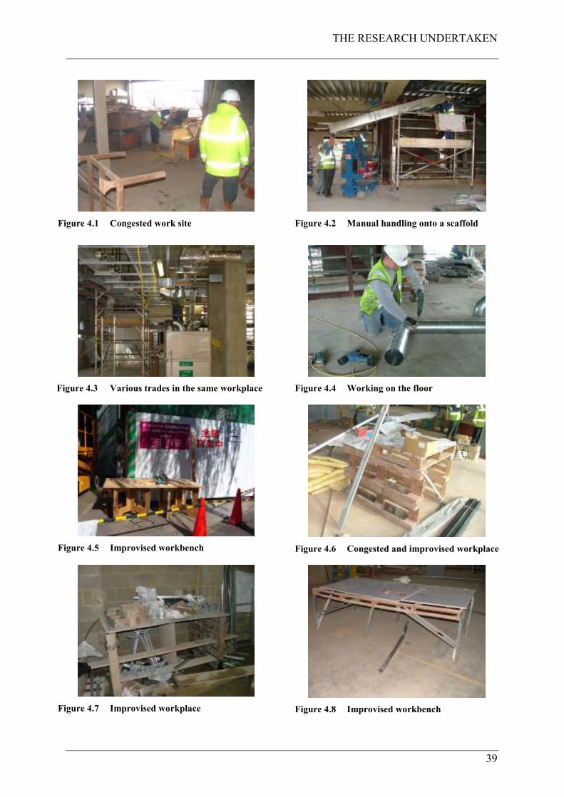
THE RESEARCH UNDERTAKEN
39
Figure 4.1 Congested work site
Figure 4.2 Manual handling onto a scaffold
Figure 4.3 Various trades in the same workplace
Figure 4.4 Working on the floor
Figure 4.5 Improvised workbench
Figure 4.6 Congested and improvised workplace
Figure 4.7 Improvised workplace
Figure 4.8 Improvised workbench
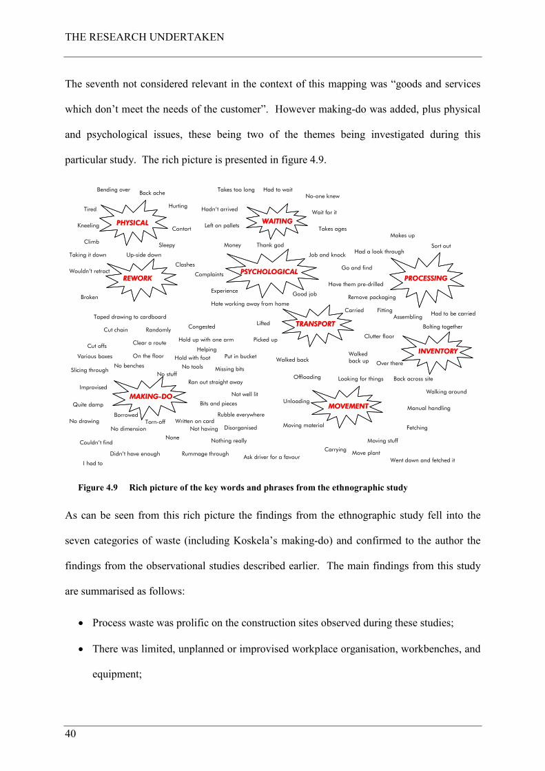
THE RESEARCH UNDERTAKEN
40
The seventh not considered relevant in the context of this mapping was “goods and services
which don’t meet the needs of the customer”. However making-do was added, plus physical
and psychological issues, these being two of the themes being investigated during this
particular study. The rich picture is presented in figure 4.9.
Bending overBack ache
Kneeling
Climb
Hurting
Contort
Sleepy
Takes too long Had to waitNo-one knew
Tired Hadn’t arrived
Takes ages
Go and find
Remove packaging
Wait for it
Left on pallets
AssemblingFitting
Had to be carried
Had a look throughSort out
Makes up
Have them pre-drilled
Bolting together
Hold up with one arm
Randomly
Taped drawing to cardboard
Cut offs
Various boxes
Slicing through
Move plantCarrying
I had to
Over there
Walked back upWalked back
Went down and fetched it
Offloading
Unloading
Moving material
Moving stuffNothing really
Didn’t have enough
Hold with foot
Cut chainCongested
Put in bucket
Not well lit
Ask driver for a favour
Disorganised
Rummage through
NoneCouldn’t find
Rubble everywhere
No dimension Not havingTorn-off
BorrowedWritten on card
Ran out straight away
No stuff
Bits and pieces
On the floor
Missing bits
Clear a route
No toolsNo benches
No drawing
Quite damp
Helping
Improvised
Looking for things Back across site
Walking around
Manual handling
Fetching
MAKING-DOMAKING-DO
MOVEMENTMOVEMENT
PROCESSINGPROCESSING
WAITINGWAITINGPHYSICALPHYSICAL
INVENTORYINVENTORY
Clutter floor
REWORKREWORK
Taking it down
Wouldn’t retract
Broken
Up-side down
Clashes
PSYCHOLOGICALPSYCHOLOGICAL
Money Thank god
Job and knock
Complaints
Experience
Hate working away from home
Good job
TRANSPORTTRANSPORTLifted
Carried
Picked up
Figure 4.9 Rich picture of the key words and phrases from the ethnographic study
As can be seen from this rich picture the findings from the ethnographic study fell into the
seven categories of waste (including Koskela’s making-do) and confirmed to the author the
findings from the observational studies described earlier. The main findings from this study
are summarised as follows:
• Process waste was prolific on the construction sites observed during these studies;
• There was limited, unplanned or improvised workplace organisation, workbenches, and
equipment;

THE RESEARCH UNDERTAKEN
41
• Assembly work was carried out on the floor or on whatever came to hand;
• There was nowhere to hang drawings or other information;
• Materials were stored randomly around the site in no particular order, in unknown
quantities and having to fetch them yourself;
• Scaffold systems were provided that had to be accessed by climbing a ladder and
opening flaps, with no facilities to store materials or tools. If something was missing,
the worker had to climb back down to get whatever was needed;
• Tools were only provided by the tradesmen themselves; they had what they had
irrespective of their suitability;
• Various trades worked in the same area at the same time. Materials for one trade were
left in the way of other trade / trades.
Significantly the author experienced the conditions on site without intervention and the
physical discomfort felt as a result16.
4.3.4 Pilot experimental study
At this point in the research process a pilot experimental study was devised to test
interventions designed to overcome the issues found in the literature search, and those
observed and experienced in the ethnographic studies. This is described in Court et al.
(2005); this being the first paper submitted for this research project and is contained in
appendix A. This paper (paper 1) was presented at the IGLC 13 conference in Sydney,
Australia in July 2005, in the Championship: Theory. In this study trial Lean interventions
were made on a live project of the company which had positive results. These interventions
16 This includes physical back pain from bending, working on the floor and climbing up and down
scaffolds and ladders.
THE RESEARCH UNDERTAKEN
42
were the first stage of designing and implementing the Construction System and the findings
from this study were used to inform and develop the System further.
4.3.5 Summary of step 2
The issues found during the literature search, observational and ethnographic studies are
summarised in table 4.2. Each of these findings show that work undertaken in a traditional
manner (or without deliberate intervention to eliminate the cause of it) is either potentially
harming the worker or is a form of waste (in Womack and Jones terms), making-do (Koskela
2004) and improvisation (Court et al. 2005) all leading to poor productivity. Collectively
these research findings informed the author what needed to be done, which was to:
• Avoid congestion on site in order to improve workers output and avoid creating
hazards;
• Use methods to avoid relationships between subcycles and work crews that exist and
delay and interfere with each other;
• Improve construction workers occupational health as well as their safety by providing
good ergonomics, appropriate working tools and a good working environment;
• Exploit the use of prefabricated modules and use mechanical aids to lift them, thereby
improving workers posture carrying out simpler assembly tasks;
• Use innovative components and systems to replace outdated components and processes;
• Supply the right parts to the right place and at the right time to avoid poorly conceived
materials handling strategies leading to poor site productivity;
• Avoid poor workplace management (housekeeping and tidiness);
• Avoid designing work that uses site workers that are in short supply or inappropriately
skilled.
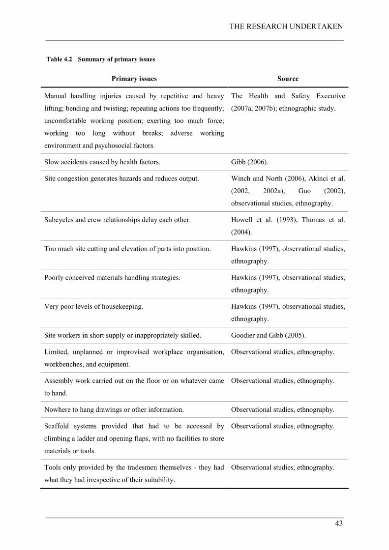
THE RESEARCH UNDERTAKEN
43
Table 4.2 Summary of primary issues
Primary issues Source
Manual handling injuries caused by repetitive and heavy
lifting; bending and twisting; repeating actions too frequently;
uncomfortable working position; exerting too much force;
working too long without breaks; adverse working
environment and psychosocial factors.
The Health and Safety Executive
(2007a, 2007b); ethnographic study.
Slow accidents caused by health factors. Gibb (2006).
Site congestion generates hazards and reduces output. Winch and North (2006), Akinci et al.
(2002, 2002a), Guo (2002),
observational studies, ethnography.
Subcycles and crew relationships delay each other. Howell et al. (1993), Thomas et al.
(2004).
Too much site cutting and elevation of parts into position. Hawkins (1997), observational studies,
ethnography.
Poorly conceived materials handling strategies. Hawkins (1997), observational studies,
ethnography.
Very poor levels of housekeeping. Hawkins (1997), observational studies,
ethnography.
Site workers in short supply or inappropriately skilled. Goodier and Gibb (2005).
Limited, unplanned or improvised workplace organisation,
workbenches, and equipment.
Observational studies, ethnography.
Assembly work carried out on the floor or on whatever came
to hand.
Observational studies, ethnography.
Nowhere to hang drawings or other information. Observational studies, ethnography.
Scaffold systems provided that had to be accessed by
climbing a ladder and opening flaps, with no facilities to store
materials or tools.
Observational studies, ethnography.
Tools only provided by the tradesmen themselves - they had
what they had irrespective of their suitability.
Observational studies, ethnography.
THE RESEARCH UNDERTAKEN
44
These research findings for the current state allowed a basis of understanding to commence
the next step in the research process which was data collection for the future state (the vision
of how things could be).
4.4 STEP 3: DATA COLLECTION FOR THE FUTURE STATE
This step in the research process involved data collection for the future state and continued the
action research method. It included a literature search for the future vision, looking inside and
outside the industry for best practice and innovation using observational studies. This step in
the research process began with a taught module at Loughborough University; Lean and Agile
Manufacture (Module 04MMP203), which was the turning point for the author in
understanding manufacturing methods in use today. Understanding these efficient methods
and systems used in manufacturing provided a firm foundation and framework for being able
to implement leading edge manufacturing techniques into the construction industry. The
elements of the taught module were:
• Lean and agile manufacturing;
• Production planning and control in lean systems;
• The cellular business (the effect of lean and agile);
• Issues with lean manufacture;
• Period batch control and inventory management;
• Optimised production technology;
• Theory of constraints; real time scheduling and demand management;
• Postponement strategies.
Following the learning from this module, manufacturing was seen as a rich source of efficient
techniques and methods for possible adoption into construction. The primary manufacturing
THE RESEARCH UNDERTAKEN
45
methods therefore further researched were: Lean and agile manufacturing with postponement;
modular assembly; reflective manufacture; period flow control; ABC parts classification and
vehicle assembly. Ergonomics17 was also included because of its importance to
manufacturing workplace design.
4.4.1 Literature search
4.4.1.1 Lean and agile manufacturing with postponement
Techniques in Lean tend to suit the highly efficient producer, particularly the production of
high variety commodity items at minimum cost. Lean is efficient but can it also be
responsive? Lean seems to be much more appropriate for efficiency and cost cutting, whereas
agility is the ability to rapidly reconfigure the production system (and the supply and
distribution systems) to meet new product requirements. Agility has a responsiveness
dimension which does not seem to be part of the Lean definition. It is possible to link
different sorts of systems together using the concept of the decoupling point, for example the
Lean factory can be separated from the agile distribution chain by means of a decoupling
store. The factory produces modules that are placed in the store and as the demand changes
the modules can be quickly assembled in the distribution chain to provide the customer with a
unique offering. If the decoupler is moved very close to the customer so that it is far
downstream and the module store is close to the retailer then you have a form postponement
strategy where there is the means to rapidly assemble the product to meet the precise customer
order. If the distribution of the product is delayed to the last minute and only configured and
distributed when the customer order is received then you have logistics postponement (Yang
and Burns 2003). According to Mason-Jones et al. (2000), Lean and agile paradigms, though
17 Whilst ergonomics is not a manufacturing method itself, vehicle assembly according to Granath (1998)
requires good ergonomics, this being the reason for review here.

THE RESEARCH UNDERTAKEN
46
distinctly different, can be and have been combined within successfully designed and operated
supply chains (this is known as Leagility). Naylor et al. (1999), define Leagility as:
“…the combination of the Lean and agile paradigm within a total supply chain strategy
by positioning the decoupling point so as best to suit the need for responding to a volatile
demand downstream yet providing level scheduling upstream from the decoupling point.”
Postponement therefore is an approach then that helps deliver more responsive supply chains.
Form postponement which involves the delay of final manufacturing until a customer order is
received is commonly regarded as an approach to mass customisation (Skipworth and
Harrison 2004). Mass customisation is providing numerous customer chosen variations on
every order with little lead-time and cost penalty. Skipworth and Harrison proposed the
application of form postponement as a solution to deal with the high demand uncertainty
resulting from the provision of many variants whilst ensuring low operational costs are
maintained with short reliable lead times. Examples of how product architecture enables
postponement are given in Ulrich and Eppinger (2004). They link the product architectural
choices to platform planning, this being the collection of assets including component designs
shared by products.
4.4.1.2 Modular assembly
According to Fredriksson (2006), modularity is a design strategy that is used by companies
producing such different products as aircraft, household appliances, trucks and cars,
computers and software. The popularity of the concept he describes is explained by its
appealing logic, which is to divide a complex system into decoupled and manageable modules
that are easily put together into a working whole. A definition of this is given as:
THE RESEARCH UNDERTAKEN
47
“…the ability to pre-combine a large number of components into modules and for these
modules to be assembled off-line and then bought onto the main assembly line and
incorporated through a small and simple series of tasks”.
Modularity in production thus implies a dispersed assembly system in which some activities
are pre-assembly (of components into modules) and other activities are final assembly (of
components and modules into end-products).
4.4.1.3 Reflective manufacture and quality of work
Reflective manufacture is an important socio-technical approach to manufacture that arose in
Sweden at the Volvo Uddevalla plant. Its evolution is described by Granath (1998) and is
regarded in Sweden as a person centred approach to automobile assembly although it was
never fully developed. It is now attracting more attention with the development of mass
customisation strategies. Reflective systems do vary in the way that they are designed,
however they tend to suit a highly modularised product. The research found that Volvo, when
looking into the development of production systems, looked into quality of work as well as
efficiency of production. According to Granath, quality of work contains a number of
aspects; he suggests that a system that offers professional meaningful work is better than
those that only offer unskilled or semi-skilled work. The aspects that signify professional
work are control over methods, time and quality plus the responsibility to plan ahead and the
knowledge needed to reflect on work done. Quality of work also requires good ergonomics,
appropriate working tools and a good working environment.
A typical form of reflective system generally has module build units or cells, each the
responsibility of a semi-autonomous team. Team members are multi-skilled and highly
trained so that they are interchangeable. There are likely to be standard operating procedures
THE RESEARCH UNDERTAKEN
48
(SOP’s) but members themselves generally design these. In these systems there is often a
significant materials acquisition unit with a kitting function and the system operates using a
pulse-system or period batch control. Period batch control (also know as period flow control)
is a Just-In-Time, flow control, single cycle, production control method based on a series of
short standard periods generally of one week or less (Burbidge 1996). Alternatively the
system operates using ABC parts classification.
4.4.1.4 ABC parts classification
According to Hopp and Spearman (2001), in most manufacturing systems a small fraction of
the purchased parts represent a large fraction of purchasing expenditures, so management
should therefore focus most attention on these parts. To accomplish this, ABC classification
is used by many manufacturing firms for categorising and managing purchased parts and
materials. Parts have been classified by Hopp and Spearman as follows:
A parts The first 5 to 10 percent of the parts accounting for 75 to 80 percent of
expenditure;
B parts The next 10 to 15 percent of the parts accounting for 10 to 15 percent of
expenditure;
C parts The bottom 80 percent or so of the parts accounting for only 10 percent or so of
expenditure.
It makes sense therefore to use appropriate methods to tightly coordinate the arrival of A
parts. The cost of holding small excess quantities of C parts is not large therefore such
methods would not be required for these. B parts are in between so they deserve more
attention than C parts, but less than A parts. The main point of this is that inventories of
different classes of parts should be treated differently. As stated, type A parts are expensive
THE RESEARCH UNDERTAKEN
49
and bulky, for which stockholding is costly (and a waste in Lean terms – the waste of
inventory). The way to therefore manage these expensive parts (according to Hopp and
Spearman), is to keep levels to an absolute minimum which is precisely the idea behind Just-
In-Time (JIT). For these reasons the ABC method was adopted for use because of its high
degree of suitability and applicability to the Construction System (and is a component
classification method used in reflective manufacture). No other method was therefore
considered.
4.4.1.5 Ergonomics
Ergonomics is a theme that the author sought to understand to be able to design work cells
that were suitable for the worker carrying out their designated work. It is a science devoted to
determining the range of anatomical, physiological and psychological human factors and
designing work environments conducive to these ranges with the objective of maximising
productivity and minimising injury (McNamara, 1986).
According to the Health and Safety Executive, in their publication “Understanding
Ergonomics at Work” (HSE 2003), ergonomics is a science concerned with the ‘fit’ between
people and their work. It puts people first taking account of their capabilities and limitations.
Ergonomics aims to make sure that tasks, equipment, information and the environment suit
each worker. By assessing the relevant aspects of people, their jobs, equipment, the working
environment and the interaction between them, ergonomists are able to design safe, effective
and productive work systems.
To date most of the literature reviewed relating to ergonomics in construction reveals research
in the health and safety field covering:
THE RESEARCH UNDERTAKEN
50
• Health and Safety in construction generally (Koningsveld and Van Der Molen 1997,
HSE 2007);
• Manual handling (Sillanpaa et al. 1999, HSE 2000);
• Working posture (Abdelhamid and Everett 1999, Kivi and Mattila 1991, Sporrong et al.
1999);
• Overexertion (Everett 1999);
• Musculoskeletal disorders (HSE 2007a, 2007b).
Of particular relevance to this research project are the findings in Sillanpaa et al. (1999). This
research found that by using auxiliary handling devices (wheels, lifting straps and
workbenches) significant reduction in the muscular load on the workers being tested was
experienced when compared to conventional work methods (manual lifting and working bent
over on the floor). It was not the intention of this research project to conduct more studies
into these factors but to be able to take due cognisance of them. The aim was to be able to
design safer, more effective and productive workplaces and systems for M&E workers that
considered the basics of ergonomics. This also meant designing work to fit the worker18 and
not fitting the worker to the work (Bridger 2003). A key learning point for the author was
that if you approach the design of work from an ergonomic perspective two things happen as
a natural by-product: work becomes safer for the worker and the worker becomes more
productive. This is because work itself is designed to be safer, more effective and productive.
18 Bridger (2003) uses the phrases “fitting the job to the man (FJM)” and “fitting the man to the job
(FMJ)”. The author prefers to use the phrases “designing work to fit the worker” and “fitting the worker
to the work”.
THE RESEARCH UNDERTAKEN
51
4.4.2 Observational studies
A further observational study was undertaken in order to formulate an understanding of
manufacturing methods in the context of this research. This study was conducted at the
BMW “Mini” factory in Cowley, UK. This was to observe the assembly of car bodies and the
final car assembly process. This was to give the author a feel for a manufacturing and
assembly environment and how people worked. Importantly, the author, by observing the
various assembly processes conducted either by robots or people, was able to get many visual
clues as to how the methods could be transferred to M&E construction. These visual clues
included (most significant):
• A logistics team delivering components trackside, directly to point of use and Just-In-
Time;
• Conveyors delivering modules (engines, dashboards etc.) exactly on time when the
particular car body arrived at the assembly station;
• No manual handling by assembly workers other than small parts;
• Work cells with everything to hand. Workers were allowed some discretion in
organising their own assembly / work cell;
• Car bodies rotating so that components could be fitted to the bottom of the car without
the need for the worker to do this from below;
• Simple assembly processes to build a complex product – modular assembly;
• Precise timing of vehicle arriving at workstation, with work cells, components,
everything synchronised perfectly;
• Clean and tidy workplace, no mess, minimum inventories required;
• Visual management aids;
THE RESEARCH UNDERTAKEN
52
• Senior managers spending one week per year in each plant on the factory floor doing
actual work. A financial manager was witnessed loading sheet steel onto a conveyor
ready for processing.
Photographs were not allowed during the factory visit so these visual clues served as a
reminder of what could be possible and set a foundation for thinking about these methods
being applicable and transferable to M&E construction.
4.4.3 Summary of step 3
Taken together, these collective research findings formed the underpinning techniques and
methods used for the design of the Construction System to specifically address the research
problem with appropriate countermeasures. This set the platform for the next step in the
research process, breakthrough thinking for development of options for analysis.
4.5 STEP 4: BREAKTHROUGH THINKING FOR DEVELOPMENT
OF OPTIONS FOR ANALYSIS
The next step in the research process was to bring together the learning in the previous steps
in order to facilitate what was termed as breakthrough thinking for development of options for
analysis, however ideas became apparent and developed as the learning progressed through
the previous research steps. The ideas were bought together when thinking through each of
the research findings and the manufacturing methods that could be used to countermeasure the
research problem. The thinking culminated in the development of the conceptual
Construction System model which is the subject of the second paper submitted for the
Engineering Doctorate and is described in Court et al. (2006) and is contained in appendix B.
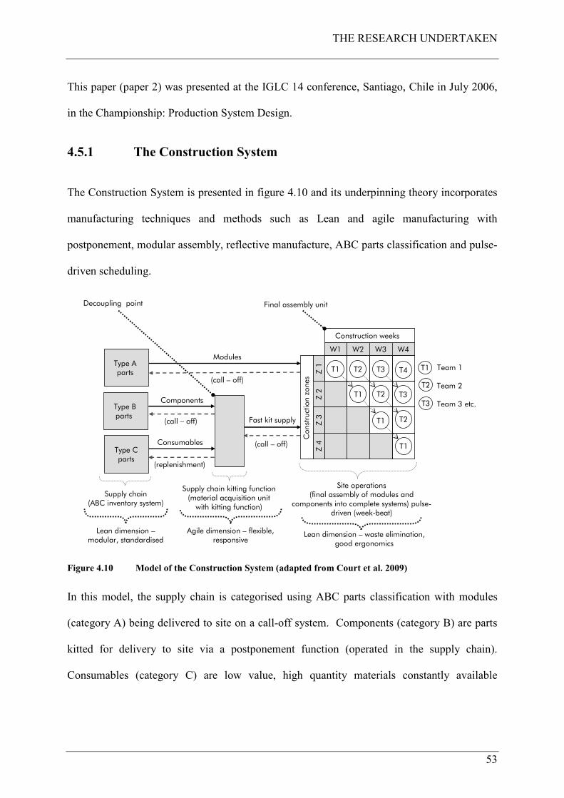
THE RESEARCH UNDERTAKEN
53
This paper (paper 2) was presented at the IGLC 14 conference, Santiago, Chile in July 2006,
in the Championship: Production System Design.
4.5.1 The Construction System
The Construction System is presented in figure 4.10 and its underpinning theory incorporates
manufacturing techniques and methods such as Lean and agile manufacturing with
postponement, modular assembly, reflective manufacture, ABC parts classification and pulse-
driven scheduling.
Type A parts
Type B parts
Type Cparts
Supply chain(ABC inventory system)
Fast kit supply(call – off)
Supply chain kitting function(material acquisition unit with kitting function)
(replenishment)
Modules
(call – off)
Components
Consumables
(call – off)
Z 2
W1 W2 W3 W4
Z 1
Z 3
Z 4
T1
Construction zones
Construction weeks
Team 1
Team 2
Team 3 etc.
Site operations (final assembly of modules and
components into complete systems) pulse-driven (week-beat)
T2
T3
Agile dimension – flexible, responsive
Lean dimension –modular, standardised
Final assembly unit
Lean dimension – waste elimination, good ergonomics
Decoupling point
T1
T1
T1
T1
T2
T2
T2
T3
T3
T4
Figure 4.10 Model of the Construction System (adapted from Court et al. 2009)
In this model, the supply chain is categorised using ABC parts classification with modules
(category A) being delivered to site on a call-off system. Components (category B) are parts
kitted for delivery to site via a postponement function (operated in the supply chain).
Consumables (category C) are low value, high quantity materials constantly available

THE RESEARCH UNDERTAKEN
54
supplied by a kanban19 replenishment system. Site operations are conducted by semi-
autonomous trade teams (T1, T2 etc), using mobile work cells and ergonomic access
equipment (Court et al. 2005) specifically designed for their activity. The System operates
using a pulse-driven which has been called the Week-Beat (this is the Systems takt20 time),
the pulse rate or takt time being one week.
The supply chain element of the Construction System provides the Lean dimension, this being
modular and standardised. M&E distribution systems are pre-combined into modules (type A
parts) and these modules are to be assembled off-line (at CHt’s and other suppliers
manufacturing centres) and then brought onto the main assembly line (the construction site –
the final assembly unit) and incorporated through a small and simple series of tasks (in each
construction zone and plantroom).
The postponement function (the decoupling point) provides agility in that each trade team (the
customer – the next person or step in the process, Liker 2004) gets exactly what they want,
when they want it and where they want it, delivered to point of use by a logistics team. This
postponement function is to be carried out in the supply chain and is not a physical place in its
own right. The site operations component (final assembly unit) provides a further Lean
dimension with methods that eliminate process waste (muda). All teams are to be provided
with good ergonomics, appropriate working tools and a good working environment (Granath
1998) in the form of specifically designed mobile work cells suitable for their specific tasks.
These Lean and agile attributes are designed to standardise the work, process and products to
19 A kanban is a signal that gives authorisation and instructions in a pull system (the Lean Enterprise
Institute 2003).
20 Takt time is a German word for a pace or a beat, often liked to a conductor’s baton. Takt time is a
reference number that is used to help match the rate of production in a pacemaker process to the rate of
sales (Rother and Harris 2001).

THE RESEARCH UNDERTAKEN
55
create flow, pull and value delivery. The ergonomic and workplace organisation attributes are
to be designed to specifically improve workers health, safety and productive output (Court et
al. 2005).
The System operates using a pulse-driven system which has been called the Week-Beat (the
pulse rate is one week). Here each team is to have one week in each construction zone
(approximately 1,000 square meters) to complete its work before moving to the next zone and
so on. The next team, T2, follows on at the Week-Beat interval and the next team follows
similarly. The Week-Beat method described here is specifically aimed at ensuring that no two
or more trades work in the same place at the same time unless allowed to do so (when still
separated by physical space). This will prevent subcycles or crews interfering with each
others progress and to provide an uninterrupted flow of work in their own clear space. The
beat of the System is one week because this period matches the quantity of work to be done
by an optimum amount of workers in that space. For instance each construction zone has
approximately 450 metres of ventilation ductwork to be fitted. One pair of workers can fit
22.5 metres of ductwork per day (higher productivity rate allowed – usually 17.5 metres per
pair per day), therefore when allowing four days to do this work (with one day safety buffer),
five pairs of workers are required. With all their equipment and materials, 10 workers are
about on the limit for the space capacity within a 1,000 square metre construction zone.
Where longer periods are required for other trades to carry out their work in this sized space,
such as partitioning work21, then this is treated as a bottleneck in the System and how it is
managed is described later in this chapter. Another Lean feature of the Construction System
which to be deployed is the Last Planner System (LPS) of production control which is also
described later.
21 Also known as dry-lining.
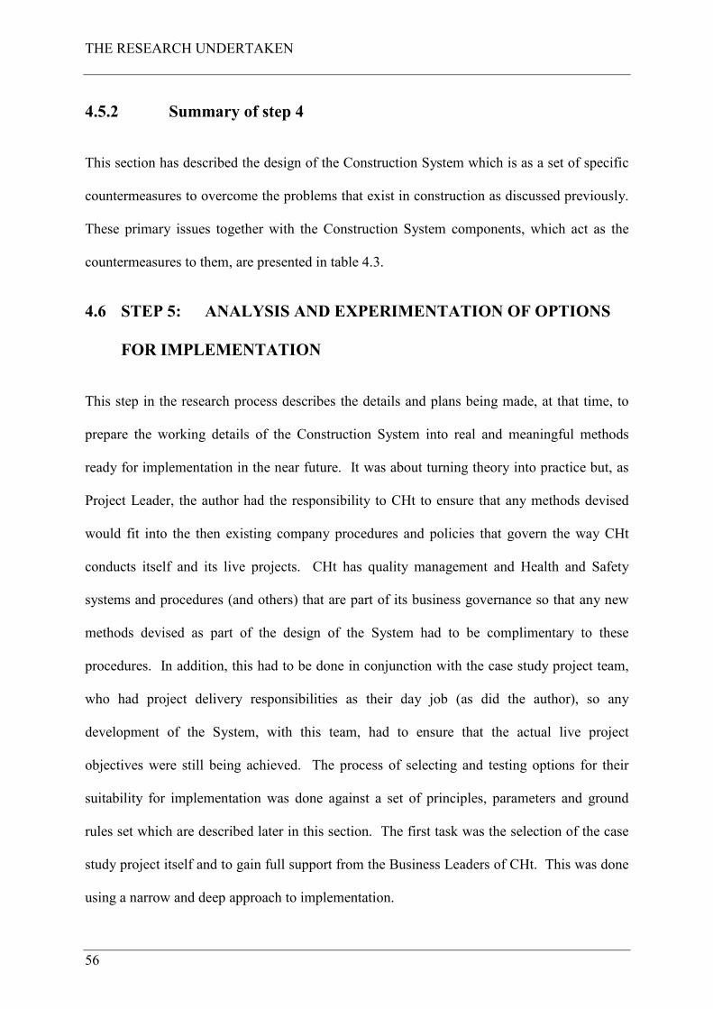
THE RESEARCH UNDERTAKEN
56
4.5.2 Summary of step 4
This section has described the design of the Construction System which is as a set of specific
countermeasures to overcome the problems that exist in construction as discussed previously.
These primary issues together with the Construction System components, which act as the
countermeasures to them, are presented in table 4.3.
4.6 STEP 5: ANALYSIS AND EXPERIMENTATION OF OPTIONS
FOR IMPLEMENTATION
This step in the research process describes the details and plans being made, at that time, to
prepare the working details of the Construction System into real and meaningful methods
ready for implementation in the near future. It was about turning theory into practice but, as
Project Leader, the author had the responsibility to CHt to ensure that any methods devised
would fit into the then existing company procedures and policies that govern the way CHt
conducts itself and its live projects. CHt has quality management and Health and Safety
systems and procedures (and others) that are part of its business governance so that any new
methods devised as part of the design of the System had to be complimentary to these
procedures. In addition, this had to be done in conjunction with the case study project team,
who had project delivery responsibilities as their day job (as did the author), so any
development of the System, with this team, had to ensure that the actual live project
objectives were still being achieved. The process of selecting and testing options for their
suitability for implementation was done against a set of principles, parameters and ground
rules set which are described later in this section. The first task was the selection of the case
study project itself and to gain full support from the Business Leaders of CHt. This was done
using a narrow and deep approach to implementation.
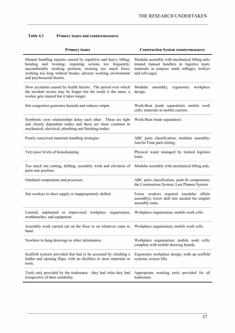
THE RESEARCH UNDERTAKEN
57
Table 4.3 Primary issues and countermeasures
Primary issues Construction System countermeasures
Manual handling injuries caused by repetitive and heavy lifting;
bending and twisting; repeating actions too frequently;
uncomfortable working position; exerting too much force;
working too long without breaks; adverse working environment
and psychosocial factors.
Modular assembly with mechanical lifting aids;
trained manual handlers in logistics team;
materials in purpose made stillages, trolleys
and roll-cages.
Slow accidents caused by health factors. The period over which
the incident occurs may be longer but the result is the same, a
worker gets injured but it takes longer.
Modular assembly; ergonomic workplace
design.
Site congestion generates hazards and reduces output. Week-Beat (trade separation); mobile work
cells; materials in mobile carriers.
Symbiotic crew relationships delay each other. These are tight
and closely dependant trades and these are more common in
mechanical, electrical, plumbing and finishing trades.
Week-Beat (trade separation).
Poorly conceived materials handling strategies. ABC parts classification; modular assembly;
Just-In-Time parts kitting.
Very poor levels of housekeeping. Physical waste managed by trained logistics
team.
Too much site cutting, drilling, assembly work and elevation of
parts into position.
Modular assembly with mechanical lifting aids.
Outdated components and processes. ABC parts classification; push-fit components;
the Construction System; Last Planner System.
Site workers in short supply or inappropriately skilled. Fewer workers required (modular offsite
assembly); lower skill mix needed for simpler
assembly tasks.
Limited, unplanned or improvised workplace organisation,
workbenches, and equipment.
Workplace organisation; mobile work cells.
Assembly work carried out on the floor or on whatever came to
hand.
Workplace organisation; mobile work cells.
Nowhere to hang drawings or other information. Workplace organisation; mobile work cells;
complete with mobile drawing boards.
Scaffold systems provided that had to be accessed by climbing a
ladder and opening flaps, with no facilities to store materials or
tools.
Ergonomic workplace design; walk-up scaffold
systems; scissor lifts.
Tools only provided by the tradesmen - they had what they had
irrespective of their suitability.
Appropriate working tools provided for all
tradesmen.
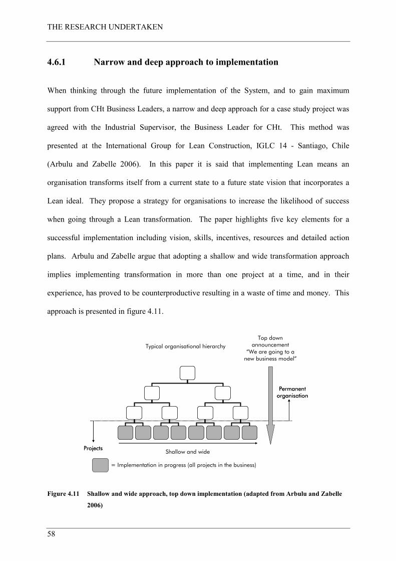
THE RESEARCH UNDERTAKEN
58
4.6.1 Narrow and deep approach to implementation
When thinking through the future implementation of the System, and to gain maximum
support from CHt Business Leaders, a narrow and deep approach for a case study project was
agreed with the Industrial Supervisor, the Business Leader for CHt. This method was
presented at the International Group for Lean Construction, IGLC 14 - Santiago, Chile
(Arbulu and Zabelle 2006). In this paper it is said that implementing Lean means an
organisation transforms itself from a current state to a future state vision that incorporates a
Lean ideal. They propose a strategy for organisations to increase the likelihood of success
when going through a Lean transformation. The paper highlights five key elements for a
successful implementation including vision, skills, incentives, resources and detailed action
plans. Arbulu and Zabelle argue that adopting a shallow and wide transformation approach
implies implementing transformation in more than one project at a time, and in their
experience, has proved to be counterproductive resulting in a waste of time and money. This
approach is presented in figure 4.11.
Projects
Permanent organisation
Projects
Permanent organisation
Top down announcement
“We are going to a new business model”
Typical organisational hierarchy
Shallow and wide
= Implementation in progress (all projects in the business)
Figure 4.11 Shallow and wide approach, top down implementation (adapted from Arbulu and Zabelle
2006)

THE RESEARCH UNDERTAKEN
59
Arbulu and Zabelle recommend an alternative approach in their paper which is referred to as a
narrow and deep approach, taking projects themselves as the basis for transformation as part
of a business transformation process, which is presented in figure 4.12.
Time
Revenue
Current Business Model New Business Model
Break Point
Figure 4.12 Business transformation process (adapted from Arbulu and Zabelle 2006)
The main benefits of adopting this approach include (from Arbulu and Zabelle 2006):
• “Maintain current operations while transformation occurs. The objective is a smooth
transformation”;
• “Better control of when the break point occurs. The break point is defined here as the
moment where at least 50% of projects are being delivered through the new business
model”;
• “Better control of capability development. The adoption of the new business model
imposes many technical challenges for leaders and project team members”;
• “Better decision making regarding which project is next in the transformation process.
For example companies may want to gain competitive advantage faster by selecting
projects from key clients or industry sectors based on their contribution to the
organisation's revenue”;
• “The impact of top-down leadership support is higher thanks to working in a more
controlled environment (e.g., one project instead of ten). A Lean transformation
initiative requires significant time dedicated to lead teams through change”.
THE RESEARCH UNDERTAKEN
60
Figure 4.13 presents a narrow and deep approach to Lean implementation with top down
leadership support. This approach implies that the transformation process occurs from the
bottom up, in other words from the projects themselves.
Projects
Permanent organisation
Bottom up implementation approach
Typical organisational hierarchy
Narrow and deep
= North Staffordshire Hospitals Project (this case study)
Narrow and deep
= North Staffordshire Hospitals Project (this case study)
Top down leadership support
Figure 4.13 Narrow and deep approach, bottom up implementation (adapted from Arbulu and Zabelle
2006)
This was the method agreed for implementation on the case project with full top down
leadership support from CHt. As Arbulu and Zabellle state, the construction industry has a
key advantage compared with other industries regarding how to approach a sustainable Lean
transformation and this advantage is having projects. These projects enable the design and
implementation of temporary business systems and can be the basis for transformation, the
means to create a new business model (figure 4.12). CHt has projects and a further advantage
is that the thesis author is a Project Leader in the company and in particular the North
Staffordshire Hospitals Project in Stoke-on-Trent, Staffordshire, UK. This project therefore
became the subject of the narrow and deep approach and was the case study project where the
Construction System was implemented and tested as part of this research project.
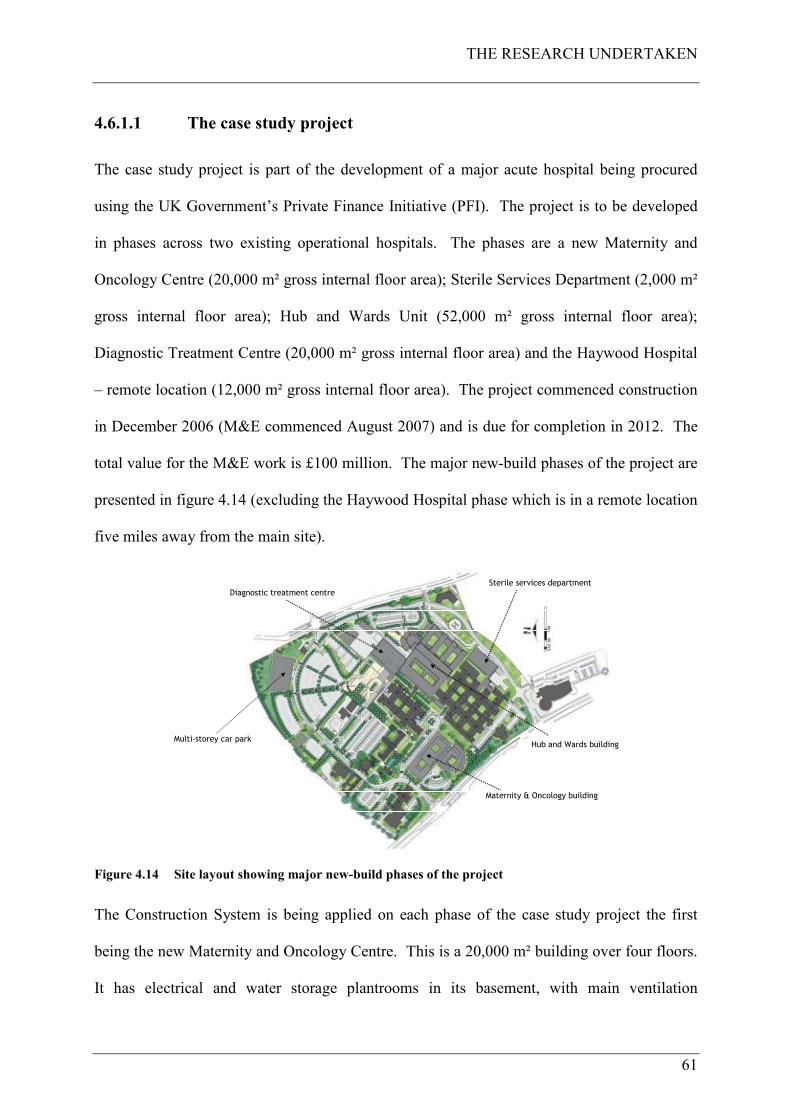
THE RESEARCH UNDERTAKEN
61
4.6.1.1 The case study project
The case study project is part of the development of a major acute hospital being procured
using the UK Government’s Private Finance Initiative (PFI). The project is to be developed
in phases across two existing operational hospitals. The phases are a new Maternity and
Oncology Centre (20,000 m² gross internal floor area); Sterile Services Department (2,000 m²
gross internal floor area); Hub and Wards Unit (52,000 m² gross internal floor area);
Diagnostic Treatment Centre (20,000 m² gross internal floor area) and the Haywood Hospital
– remote location (12,000 m² gross internal floor area). The project commenced construction
in December 2006 (M&E commenced August 2007) and is due for completion in 2012. The
total value for the M&E work is £100 million. The major new-build phases of the project are
presented in figure 4.14 (excluding the Haywood Hospital phase which is in a remote location
five miles away from the main site).
Multi-storey car park
Maternity & Oncology building
Sterile services department
Diagnostic treatment centre
Hub and Wards buildingMulti-storey car park
Figure 4.14 Site layout showing major new-build phases of the project
The Construction System is being applied on each phase of the case study project the first
being the new Maternity and Oncology Centre. This is a 20,000 m² building over four floors.
It has electrical and water storage plantrooms in its basement, with main ventilation
THE RESEARCH UNDERTAKEN
62
plantrooms over the Oncology Centre at level two and on the roof at level five. Riser shafts
are located around the building and distribute air, water, medical gas, electricity and the like
throughout the building to the various departments. Corridor ceiling voids distribute the
services from the riser shafts and then further into individual rooms and spaces, again in the
ceiling voids. Finally services distribute inside dry-lined walls to points of use such as
electrical sockets, sinks, basins and bed-head units; everything you would expect to see in a
new and modern healthcare facility.
4.6.1.2 Conditions for success
Arbulu and Zabelle (2006) outline five key elements that are required for successful
implementation and state that these should be used as a checklist prior to commencing any
implementation effort, and these are listed below.
1 Vision - “Without a vision stakeholders will be confused. Creating a vision sets the
framework for the mission, objectives and strategies for the implementation effort at the
project level”.
2 Skills - “If skills are missing during any Lean transformation process, people will be
anxious. This applies to project team members, top management, and anyone that plays
a role in the implementation effort. Skills are instilled in the selected project team
through training. Training is one of the most important aspects of managing change
because it fills the gaps between the current business model and the new business
model”.
3 Incentive - “If an effective incentive scheme is missing, change will be gradual. The
new systems and methods of working may eventually be adopted as project teams begin
to see the benefits, but the change will most likely take longer than desired”.

THE RESEARCH UNDERTAKEN
63
4 Resources - “If resources are insufficient, frustration will be the end result. It is critical
to provide sufficient resource to support the implementation effort. Teams will need to
be facilitated, individuals will need to be trained, and managers will need to be
coached”.
5 Action Plan - “If a solid action plan is not in place, the likely result will be a false start.
In an effort to make progress, teams will start down one path of action without knowing
if this is the right path…It is therefore essential to agree a plan of action for the
implementation effort with Project Leadership”.
They state that if one or more of the elements are not in place then the implementation effort
will most likely fail. Table 4.4 outlines the probable outcome if one of the elements is
missing. Using these elements as a checklist, each was worked through in order to plan the
actual implementation and to ensure that all the elements for successful implementation were
in place according to this method.
Table 4.4 Elements for successful implementation (adapted from Arbulu and Zabelle, 2006)
Result Vision Skill Incentive Resources Action plan
Change Yes Yes Yes Yes Yes
Confusion No Yes Yes Yes Yes
Anxiety Yes No Yes Yes Yes
Gradual change Yes Yes No Yes Yes
Frustration Yes Yes Yes No Yes
False start Yes Yes Yes Yes No

THE RESEARCH UNDERTAKEN
64
4.6.1.2.1 The vision element for success
The vision element was straightforward as this was articulated by the Business Leaders of the
group of companies which is presented in figure 1.1 contained in chapter 1 of this thesis,
along with the safety vision. This is:
• To be Incident and Injury Free, returning everyone home safely after a productive days
work;
• To be the company of first choice for all stakeholders - customers, employees,
suppliers, trade contractors and the society in which we live;
• To challenge and change the poor image of construction worldwide;
• With Leanness and agility to adopt processes to compete with world-leading
businesses.
This vision flowed straight through to the vision for the case study project, and further
articulated in the stated aim for this research project described in chapter 2.
4.6.1.2.2 The skill element for success
Bringing the skill element to the project was the role of the thesis author who is the M&E
Project Leader for CHt. In this role the new Lean and agile skills acquired in undertaking this
research project to design the Construction System were directly fed into the case study
project with training and familiarisation given to the project team members. The author also
had the responsibility to set objectives for team members for their annual appraisal, and Lean
development and implementation objectives were set as part of them.
4.6.1.2.3 The incentive element for success
To a certain extent, the responsibility to set these objectives may well have influenced the
next element, the incentive. The annual appraisal scheme was directly linked to the payment
THE RESEARCH UNDERTAKEN
65
of bonus (other conditions apply). So if team members excelled at learning and implementing
Lean methods, and was reflected in their annual appraisal, this could directly lead to a
financial reward. It is known that incentives are not purely financial and money is not a key
motivating factor (despite popular belief) for most people (Maslow 1943) and that a prime
incentive is recognition itself for a job well done. The team will be recognised once the
Construction System is implemented, tested and proved successful as will the project itself.
4.6.1.2.4 The resources element for success
Resources are the next element. The project had the resources and these were the project
team members themselves, recruited by the author from within and outside of CHt. Certain
key team members have directly contributed to the core elements of the Construction System
which is described in this thesis.
4.6.1.2.5 The action plan element for success
Finally the last element is the action plan. It is essential to co-create and agree an action plan
for the implementation effort on the project. The Construction System has been under
development in conjunction with team members from the case study project from the
beginning of this research project, and its implementation is discussed in this thesis. The
action plan was therefore this research project.
Having selected the case study project along with achieving CHt top management support, the
next actions in this research step is to commence the process of turning the theory of the
Construction System into practice.
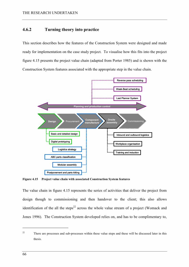
THE RESEARCH UNDERTAKEN
66
4.6.2 Turning theory into practice
This section describes how the features of the Construction System were designed and made
ready for implementation on the case study project. To visualise how this fits into the project
figure 4.15 presents the project value chain (adapted from Porter 1985) and is shown with the
Construction System features associated with the appropriate step in the value chain.
ProcurementProcurementOnsite
assembly
Onsite
assemblyComponent
manufacture
Component
manufactureDesignDesign CommissioningCommissioning
Basic and detailed designBasic and detailed design
Digital prototypingDigital prototyping
Logistics strategyLogistics strategy
ABC parts classificationABC parts classification
Inbound and outbound logisticsInbound and outbound logistics
Workplace organisationWorkplace organisation
Training and inductionTraining and induction
Postponement and parts kittingPostponement and parts kitting
Planning and production control
Last Planner SystemLast Planner System
Week-Beat schedulingWeek-Beat scheduling
Reverse pass schedulingReverse pass scheduling
Modular assemblyModular assembly
Figure 4.15 Project value chain with associated Construction System features
The value chain in figure 4.15 represents the series of activities that deliver the project from
design though to commissioning and then handover to the client; this also allows
identification of the all the steps22 across the whole value stream of a project (Womack and
Jones 1996). The Construction System developed relies on, and has to be complimentary to,
22 There are processes and sub-processes within these value steps and these will be discussed later in this
thesis.
THE RESEARCH UNDERTAKEN
67
the processes and procedures already in use within CHt, such as design and procurement.
Whilst these are not the subject of this research project they are touched by it and are
described in this chapter to allow the reader to understand the end to end project delivery
process that the Construction System fits into.
The section begins with describing the use of cross functional teams who together designed
these features with a set of guiding principles, parameters and ground rules to guide the team
through the decision making processes undertaken. The remainder of this section describes
each feature within the project value steps and how they act as countermeasures to the issues
they are designed to overcome. The section concludes with a description of the Construction
System operation and bringing it all together ready for implementation on the case study
project. To start the process of turning the theory of the Construction System into practice,
members were selected from the project team by the author to lead the design and
implementation of the working details of the Construction System into real and meaningful
methods. These are known as cross-functional teams according Liker (2004), The Toyota
Way principle 10. The team comprised:
• Offsite Manufacturing Manager;
• Planning and Production Control Manager;
• Construction and Logistics Manager;
• Case Study Project Managers, Engineers and Designers;
• Commissioning Manager;
• Procurement and Supply Chain Engineers;
• Supply Chain Members.
THE RESEARCH UNDERTAKEN
68
The initial activity was to agree upon a set of guiding principles, design parameters and
ground rules so that decisions were made in the light of these and the team would not move
forward unless each had been satisfied.
4.6.2.1 Guiding principles, parameters and ground rules
These were brought together from company policy, the case study project’s particular
requirements and the requirements for the development of the Construction System drawn
from the research process. This provided a framework for the cross-functional teams to
deliver the required outputs to meet the stated requirements. Whilst as Project Leader, the
author had power to impose these actions upon the project team, all problems and potential
solutions were discussed with all of those affected to collect their ideas and to get agreement
on a path forward; then to make decisions by consensus, thoroughly considering all options
and to implement decisions rapidly (Liker 2004). These are two of the ground rules set below
– no.’s 3 and 4, and this was done in the development of the System. Three guiding
principles were set by the team:
Principle 1 - Incident and Injury Free: People returning home safely every day after a
productive days work; minimise on-site labour; health, safety and quality shall be the over-
riding objectives of the design (drawn from company policy);
Principle 2 – Design to make the site one of assembly rather than construction: Engage in
systematic analysis of the elements and their interconnection; design for modular assembly;
design for standardisation; design solutions for re-use; engage the internal and external
supply chain to deploy expertise early in the design process – design around a product
(drawn from company policy and the research process);
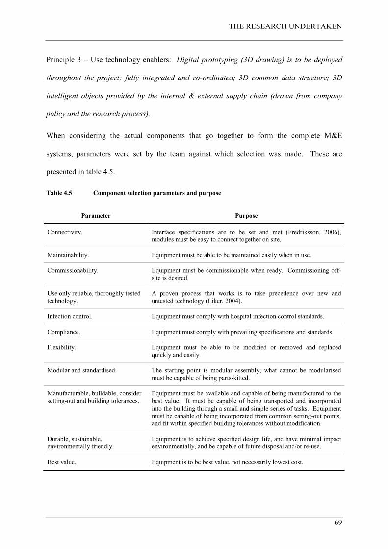
THE RESEARCH UNDERTAKEN
69
Principle 3 – Use technology enablers: Digital prototyping (3D drawing) is to be deployed
throughout the project; fully integrated and co-ordinated; 3D common data structure; 3D
intelligent objects provided by the internal & external supply chain (drawn from company
policy and the research process).
When considering the actual components that go together to form the complete M&E
systems, parameters were set by the team against which selection was made. These are
presented in table 4.5.
Table 4.5 Component selection parameters and purpose
Parameter Purpose
Connectivity. Interface specifications are to be set and met (Fredriksson, 2006),
modules must be easy to connect together on site.
Maintainability. Equipment must be able to be maintained easily when in use.
Commissionability. Equipment must be commissionable when ready. Commissioning off-
site is desired.
Use only reliable, thoroughly tested
technology.
A proven process that works is to take precedence over new and
untested technology (Liker, 2004).
Infection control. Equipment must comply with hospital infection control standards.
Compliance. Equipment must comply with prevailing specifications and standards.
Flexibility. Equipment must be able to be modified or removed and replaced
quickly and easily.
Modular and standardised. The starting point is modular assembly; what cannot be modularised
must be capable of being parts-kitted.
Manufacturable, buildable, consider
setting-out and building tolerances.
Equipment must be available and capable of being manufactured to the
best value. It must be capable of being transported and incorporated
into the building through a small and simple series of tasks. Equipment
must be capable of being incorporated from common setting-out points,
and fit within specified building tolerances without modification.
Durable, sustainable,
environmentally friendly.
Equipment is to achieve specified design life, and have minimal impact
environmentally, and be capable of future disposal and/or re-use.
Best value. Equipment is to be best value, not necessarily lowest cost.
THE RESEARCH UNDERTAKEN
70
As well as the parameters set out above; other ground rules are made to guide the team
through the process, some of which were derived from Liker (2004), The Toyota Way
principle 13:
“Make decisions slowly by consensus, thoroughly considering all options; implement
decisions rapidly.” The ground rules:
1 In finding a solution, do not create problems for other aspects of design / buildability
(derived from Liker 2004);
2 Do constructively criticise the solutions found (derived from Liker 2004);
3 Do discuss problems and potential solutions with all of those affected, to collect their
ideas and get agreement on a path forward (derived from Liker 2004);
4 Do make decisions by consensus, thoroughly considering all options; implement
decisions rapidly (derived from Liker 2004);
5 Do consider the timetable of the development when making decisions (derived from
the team);
6 Do involve the supply chain (derived from the team);
7 Do not affect the town planning constraints (derived from the team);
8 Do not affect the medical planning constraints (derived from the team);
9 Do not impact on other issues such as fire, acoustics, hospital specification’s etc.
(derived from the team);
10 Do consider the impact of the solution on the hospitals operations (derived from the
team);
11 Do find the technical solutions, do not allow programme and cost issues to inhibit
innovation until the last responsible moment (derived from the team);
12 Record the process success and failure in a log (derived from the team);
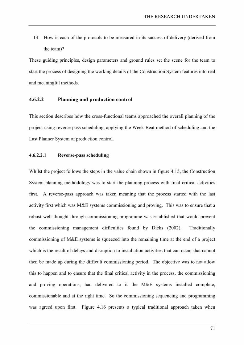
THE RESEARCH UNDERTAKEN
71
13 How is each of the protocols to be measured in its success of delivery (derived from
the team)?
These guiding principles, design parameters and ground rules set the scene for the team to
start the process of designing the working details of the Construction System features into real
and meaningful methods.
4.6.2.2 Planning and production control
This section describes how the cross-functional teams approached the overall planning of the
project using reverse-pass scheduling, applying the Week-Beat method of scheduling and the
Last Planner System of production control.
4.6.2.2.1 Reverse-pass scheduling
Whilst the project follows the steps in the value chain shown in figure 4.15, the Construction
System planning methodology was to start the planning process with final critical activities
first. A reverse-pass approach was taken meaning that the process started with the last
activity first which was M&E systems commissioning and proving. This was to ensure that a
robust well thought through commissioning programme was established that would prevent
the commissioning management difficulties found by Dicks (2002). Traditionally
commissioning of M&E systems is squeezed into the remaining time at the end of a project
which is the result of delays and disruption to installation activities that can occur that cannot
then be made up during the difficult commissioning period. The objective was to not allow
this to happen and to ensure that the final critical activity in the process, the commissioning
and proving operations, had delivered to it the M&E systems installed complete,
commissionable and at the right time. So the commissioning sequencing and programming
was agreed upon first. Figure 4.16 presents a typical traditional approach taken when
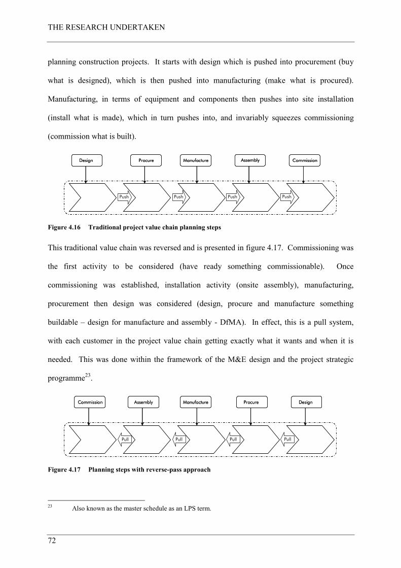
THE RESEARCH UNDERTAKEN
72
planning construction projects. It starts with design which is pushed into procurement (buy
what is designed), which is then pushed into manufacturing (make what is procured).
Manufacturing, in terms of equipment and components then pushes into site installation
(install what is made), which in turn pushes into, and invariably squeezes commissioning
(commission what is built).
Design Procure Manufacture Assembly Commission
PushPushPush Push
Design Procure Manufacture Assembly Commission
PushPushPush Push
Figure 4.16 Traditional project value chain planning steps
This traditional value chain was reversed and is presented in figure 4.17. Commissioning was
the first activity to be considered (have ready something commissionable). Once
commissioning was established, installation activity (onsite assembly), manufacturing,
procurement then design was considered (design, procure and manufacture something
buildable – design for manufacture and assembly - DfMA). In effect, this is a pull system,
with each customer in the project value chain getting exactly what it wants and when it is
needed. This was done within the framework of the M&E design and the project strategic
programme23.
DesignProcureManufactureAssemblyCommission
PullPullPull Pull
DesignProcureManufactureAssemblyCommission
PullPullPull Pull
Figure 4.17 Planning steps with reverse-pass approach
23 Also known as the master schedule as an LPS term.
THE RESEARCH UNDERTAKEN
73
Time buffers were also generated and built into the start of the commissioning activities, the
objective of which was to defend the commissioning period against any construction duration
changes that may have occurred for whatever reason. The output of the reverse-pass
scheduling was the generation of an integrated logic based master schedule setting out all of
the design, procurement, component manufacture, onsite assembly and commissioning
activities. The onsite assembly step was developed using the Week-Beat scheduling method.
4.6.2.2.2 Onsite assembly with Week-Beat scheduling
According to Rother and Harris (2001), the pace of production is one of the most critical
considerations for the design of a process. Takt time is used to help synchronise the pace of
production to the rate of sales. In the context of this research, the rate of sales must mean the
rate at which the customer (the next step in the process) requires the previous work to have
been completed so that theirs may start. Having right-sized the construction zone for a weeks
work the rate of sales must be one week. So the pace of production to achieve this must also
be one week. The Construction System was therefore designed to operate at this production
pace and has been called the Week-Beat method, with teams carrying out their work in their
own clear space, uninterrupted by other teams with their equipment and materials.
In Howell et al. (1993), it is described that productivity suffers when the output of one
subcycle delays a following step or when resources required for one subcycle are engaged in
another subcycle. The key issue is therefore balancing interdependent subcycles (Howell and
Ballard 1999a) so that all steps of the operation are part of a continuous flow process. The
Week-Beat method was designed to assure this key issue was addressed. The requirements
for the Week-Beat are as follows:
THE RESEARCH UNDERTAKEN
74
• Each team has to work at the rate at which the previous team makes the working area
available to them so as to provide a continuous flow of work (the rate of sales – takt
time);
• The size of each team may be increased or decreased but the actual pace of physical
effort is never changed (subject to resource management);
• Each team has to carry out their designated amount of work in the planned time so as to
make the working area available for the subsequent trade team;
• Timing has to be such that each team can complete their work in the zone and move to
the next zone without waiting for it to become available or starting early;
• The systems being installed have to be designed in such a way so as to facilitate this
process;
• The rate at which each item of work is carried out is to pull materials onto the site, to
the work area on a Just-In-Time basis, specifically for the task and without being stored
on the site, in kit form, on mobile carriers or roll cages;
• Access equipment and tools are to be designed specifically for the area in which the
work is to be carried out, and the rate at which the work is to progress;
• The rate at which each item of work is carried out is to pull drawings and information
onto the site, being always the latest most up to date and approved for construction.
To achieve the production pace the building was divided into construction zones each being
approximately 1,000 m²24 (zones 1-17, plantrooms 1-3) and is presented in figure 4.18.
24 1,000 m² for a construction zone is selected because this is a suitable size to enable a team to install the
required amount of individual M&E work within a week period.
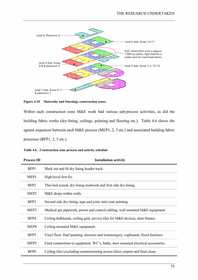
THE RESEARCH UNDERTAKEN
75
Level 1 slab: Zones 9-11 D plantroom 1
Level 3 slab: Zones 5-8 D plantroom 2
Level 4 slab: Zones 14-17
Level 5: Plantroom 3
Level 2 slab: Zones 1-4, 12-13
Each construction zone is approx. 1,000 sq metres, right sized for a weeks work for most trade teams
Figure 4.18 Maternity and Oncology construction zones
Within each construction zone M&E work had various sub-process activities, as did the
building fabric works (dry-lining, ceilings, painting and flooring etc.). Table 4.6 shows the
agreed sequences between each M&E process (MEP1, 2, 3 etc.) and associated building fabric
processes (BFP1, 2, 3 etc.).
Table 4.6 Construction zone process and activity schedule
Process ID Installation activity
BFP1 Mark out and fit dry lining header track.
MEP1 High-level first fix.
BFP2 Thin bed screed, dry-lining studwork and first side dry-lining.
MEP2 M&E drops within walls.
BFP3 Second side dry-lining, tape and joint, mist coat painting.
MEP3 Medical gas pipework, power and control cabling, wall mounted M&E equipment.
BFP4 Ceiling bulkheads, ceiling grid, service tiles for M&E devices, door frames.
MEP4 Ceiling mounted M&E equipment.
BFP5 Vinyl floor, final painting, doorsets and ironmongery, cupboards, fixed furniture.
MEP5 Final connections to equipment, WC’s, baths, door mounted electrical accessories.
BFP6 Ceiling tiles (excluding commissioning access tiles), carpets and final clean.
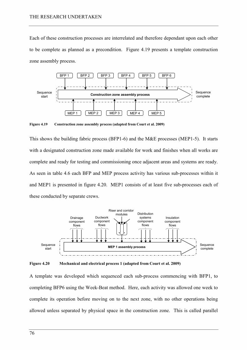
THE RESEARCH UNDERTAKEN
76
Each of these construction processes are interrelated and therefore dependant upon each other
to be complete as planned as a precondition. Figure 4.19 presents a template construction
zone assembly process.
Sequence
start
Sequence
complete
MEP 1
Construction zone assembly process
MEP 2 MEP 3 MEP 4 MEP 5
BFP 1 BFP 2 BFP 3 BFP 4 BFP 5 BFP 6
Figure 4.19 Construction zone assembly process (adapted from Court et al. 2009)
This shows the building fabric process (BFP1-6) and the M&E processes (MEP1-5). It starts
with a designated construction zone made available for work and finishes when all works are
complete and ready for testing and commissioning once adjacent areas and systems are ready.
As seen in table 4.6 each BFP and MEP process activity has various sub-processes within it
and MEP1 is presented in figure 4.20. MEP1 consists of at least five sub-processes each of
these conducted by separate crews.
MEP 1 assembly process
Drainage
component
flows
Ductwork
component
flows
Insulation
component
flows
Distribution
systems
component
flows
Riser and corridor
modules
Sequence
start
Sequence
complete
Figure 4.20 Mechanical and electrical process 1 (adapted from Court et al. 2009)
A template was developed which sequenced each sub-process commencing with BFP1, to
completing BFP6 using the Week-Beat method. Here, each activity was allowed one week to
complete its operation before moving on to the next zone, with no other operations being
allowed unless separated by physical space in the construction zone. This is called parallel
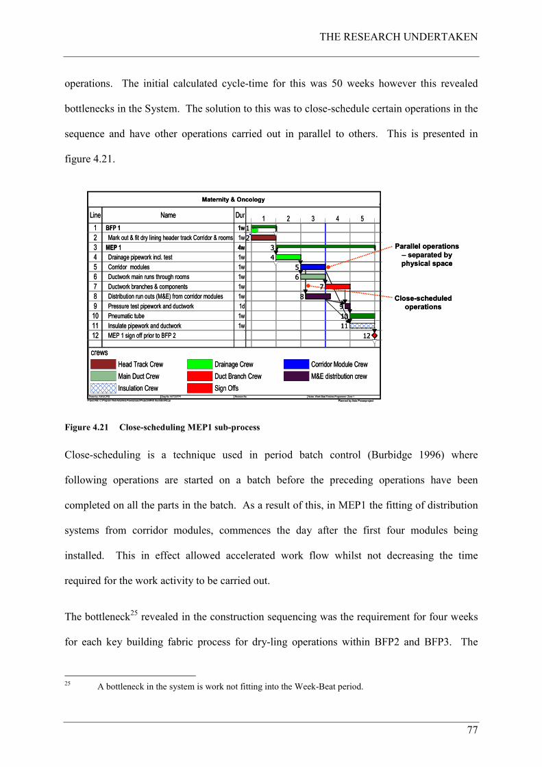
THE RESEARCH UNDERTAKEN
77
operations. The initial calculated cycle-time for this was 50 weeks however this revealed
bottlenecks in the System. The solution to this was to close-schedule certain operations in the
sequence and have other operations carried out in parallel to others. This is presented in
figure 4.21.
Maternity & Oncology>
Drawn by: AW/JC/RG Dwg No. N1733/TP1 Revision No. Notes: Week Beat Finishes Programme - Zone 1
Project Ref. C:\Program Files\Asta\Asta Powerproject\Projects\MNO IllustrationR2.pp Planned by Asta Powerproject
Line Name Dur 1 2 3 4 5
1
2
3
4
5
6
7
8
9
10
11
12
BFP 1
Mark out & fit dry lining header track Corridor & rooms
MEP 1
Drainage pipework incl. test
Corridor modules
Ductwork main runs through rooms
Ductwork branches & components
Distribution run outs (M&E) from corridor modules
Pressure test pipework and ductwork
Pneumatic tube
Insulate pipework and ductwork
MEP 1 sign off prior to BFP 2
1w
1w
4w
1w
1w
1w
1w
1w
1d
1w
1w
1
2
3
4
5
6
7
8
9
10
11
12
crews
Head Track Crew Drainage Crew Corridor Module Crew
Main Duct Crew Duct Branch Crew M&E distribution crew
Insulation Crew Sign Offs
Parallel operations
– separated by
physical space
Close-scheduled
operations
Figure 4.21 Close-scheduling MEP1 sub-process
Close-scheduling is a technique used in period batch control (Burbidge 1996) where
following operations are started on a batch before the preceding operations have been
completed on all the parts in the batch. As a result of this, in MEP1 the fitting of distribution
systems from corridor modules, commences the day after the first four modules being
installed. This in effect allowed accelerated work flow whilst not decreasing the time
required for the work activity to be carried out.
The bottleneck25 revealed in the construction sequencing was the requirement for four weeks
for each key building fabric process for dry-ling operations within BFP2 and BFP3. The
25 A bottleneck in the system is work not fitting into the Week-Beat period.
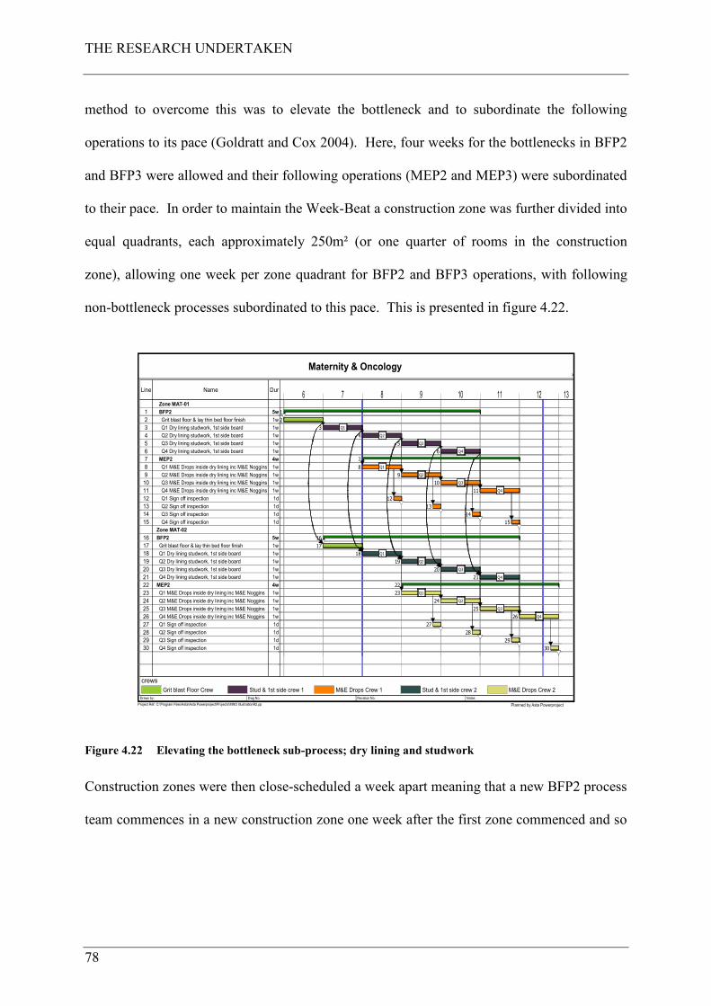
THE RESEARCH UNDERTAKEN
78
method to overcome this was to elevate the bottleneck and to subordinate the following
operations to its pace (Goldratt and Cox 2004). Here, four weeks for the bottlenecks in BFP2
and BFP3 were allowed and their following operations (MEP2 and MEP3) were subordinated
to their pace. In order to maintain the Week-Beat a construction zone was further divided into
equal quadrants, each approximately 250m² (or one quarter of rooms in the construction
zone), allowing one week per zone quadrant for BFP2 and BFP3 operations, with following
non-bottleneck processes subordinated to this pace. This is presented in figure 4.22.
Maternity & Oncology>
Drawn by: Dwg No. Revision No. Notes:
Project Ref. C:\Program Files\Asta\Asta Powerproject\Projects\MNO IllustrationR2.pp Planned by Asta Powerproject
Line Name Dur6 7 8 9 10 11 12 13
1
2
3
4
5
6
7
8
9
10
11
12
13
14
15
16
17
18
19
20
21
22
23
24
25
26
27
28
29
30
Zone MAT-01
BFP2
Grit blast floor & lay thin bed floor finish
Q1 Dry lining studwork, 1st side board
Q2 Dry lining studwork, 1st side board
Q3 Dry lining studwork, 1st side board
Q4 Dry lining studwork, 1st side board
MEP2
Q1 M&E Drops inside dry lining inc M&E Noggins
Q2 M&E Drops inside dry lining inc M&E Noggins
Q3 M&E Drops inside dry lining inc M&E Noggins
Q4 M&E Drops inside dry lining inc M&E Noggins
Q1 Sign off inspection
Q2 Sign off inspection
Q3 Sign off inspection
Q4 Sign off inspection
Zone MAT-02
BFP2
Grit blast floor & lay thin bed floor finish
Q1 Dry lining studwork, 1st side board
Q2 Dry lining studwork, 1st side board
Q3 Dry lining studwork, 1st side board
Q4 Dry lining studwork, 1st side board
MEP2
Q1 M&E Drops inside dry lining inc M&E Noggins
Q2 M&E Drops inside dry lining inc M&E Noggins
Q3 M&E Drops inside dry lining inc M&E Noggins
Q4 M&E Drops inside dry lining inc M&E Noggins
Q1 Sign off inspection
Q2 Sign off inspection
Q3 Sign off inspection
Q4 Sign off inspection
5w
1w
1w
1w
1w
1w
4w
1w
1w
1w
1w
1d
1d
1d
1d
5w
1w
1w
1w
1w
1w
4w
1w
1w
1w
1w
1d
1d
1d
1d
1
2
3
4
5
6
7
8
9
10
11
12
13
14
15
16
17
18
19
20
21
22
23
24
25
26
27
28
29
30
Q1
Q2
Q3
Q4
Q1
Q2
Q3
Q4
Q1
Q2
Q3
Q4
Q1
Q2
Q3
Q4
crews
Grit blast Floor Crew Stud & 1st side crew 1 M&E Drops Crew 1 Stud & 1st side crew 2 M&E Drops Crew 2
Figure 4.22 Elevating the bottleneck sub-process; dry lining and studwork
Construction zones were then close-scheduled a week apart meaning that a new BFP2 process
team commences in a new construction zone one week after the first zone commenced and so
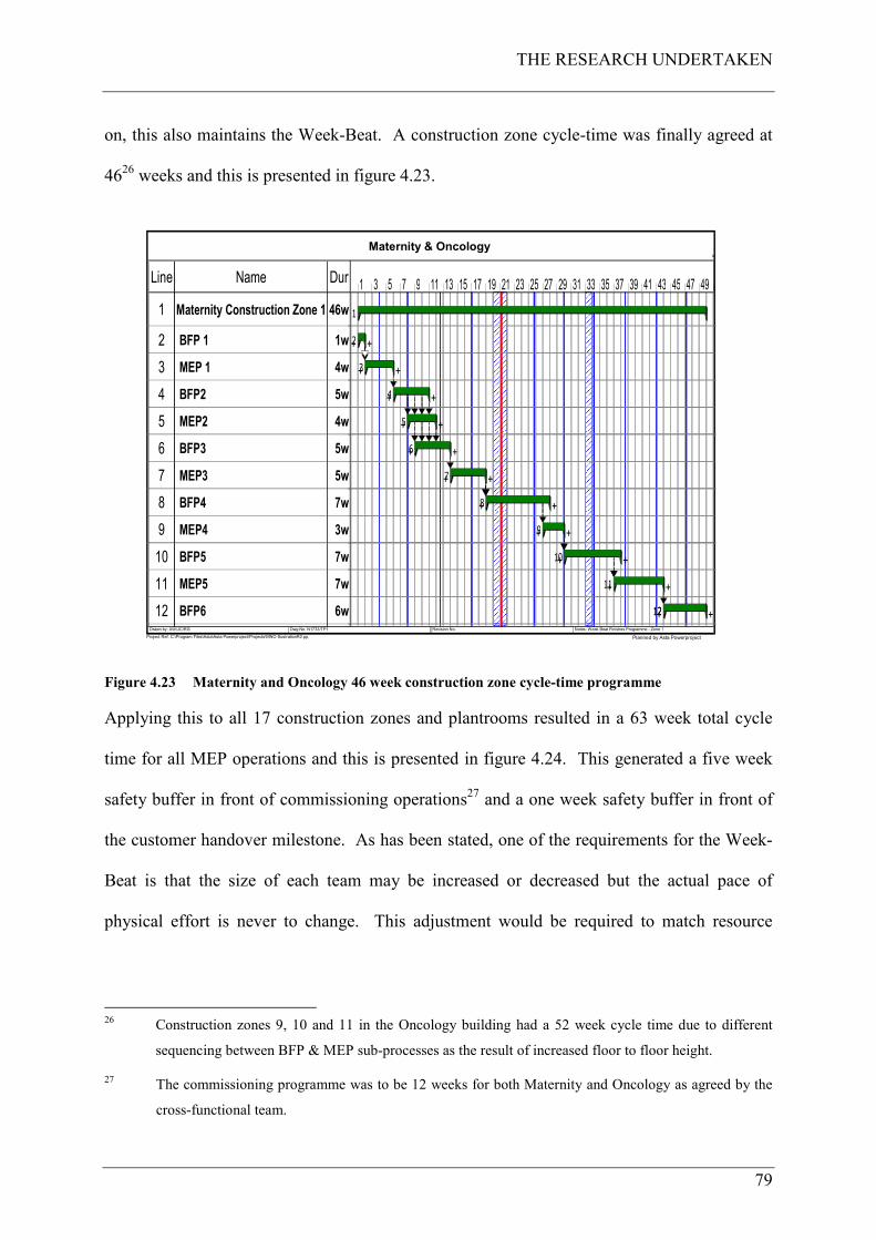
THE RESEARCH UNDERTAKEN
79
on, this also maintains the Week-Beat. A construction zone cycle-time was finally agreed at
4626 weeks and this is presented in figure 4.23.
Maternity & Oncology>
Drawn by: AW/JC/RG Dwg No. N1733/TP1 Revision No. Notes: Week Beat Finishes Programme - Zone 1
Project Ref. C:\Program Files\Asta\Asta Powerproject\Projects\MNO IllustrationR2.pp Planned by Asta Powerproject
Line Name Dur 1 3 5 7 9 11 13 15 17 19 21 23 25 27 29 31 33 35 37 39 41 43 45 47 49
1
2
3
4
5
6
7
8
9
10
11
12
Maternity Construction Zone 1
BFP 1
MEP 1
BFP2
MEP2
BFP3
MEP3
BFP4
MEP4
BFP5
MEP5
BFP6
46w
1w
4w
5w
4w
5w
5w
7w
3w
7w
7w
6w 12
1
+ +2
+ +3
+ +4
+ +5
+ +6
+ +7
+ +8
+ +9
+ +10
+ +11
+ +12
Figure 4.23 Maternity and Oncology 46 week construction zone cycle-time programme
Applying this to all 17 construction zones and plantrooms resulted in a 63 week total cycle
time for all MEP operations and this is presented in figure 4.24. This generated a five week
safety buffer in front of commissioning operations27 and a one week safety buffer in front of
the customer handover milestone. As has been stated, one of the requirements for the Week-
Beat is that the size of each team may be increased or decreased but the actual pace of
physical effort is never to change. This adjustment would be required to match resource
26 Construction zones 9, 10 and 11 in the Oncology building had a 52 week cycle time due to different
sequencing between BFP & MEP sub-processes as the result of increased floor to floor height.
27 The commissioning programme was to be 12 weeks for both Maternity and Oncology as agreed by the
cross-functional team.
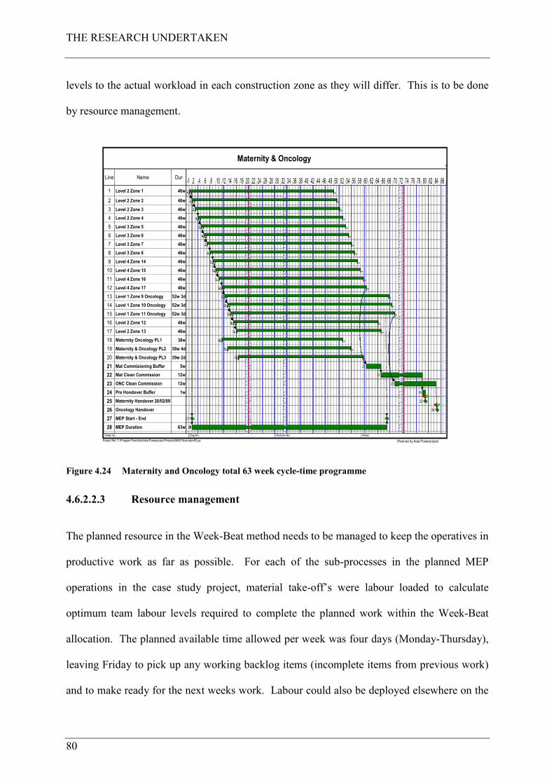
THE RESEARCH UNDERTAKEN
80
levels to the actual workload in each construction zone as they will differ. This is to be done
by resource management.
Maternity & Oncology>
Drawn by: Dwg No. Revision No. Notes:
Project Ref. C:\Program Files\Asta\Asta Powerproject\Projects\MNO IllustrationR2.pp Planned by Asta Powerproject
Line Name Dur2 4 6 8 10 12 14 16 18 20 22 24 26 28 30 32 34 36 38 40 42 44 46 48 50 52 54 56 58 60 62 64 66 68 70 72 74 76 78 80 82 84 86-1
1
2
3
4
5
6
7
8
9
10
11
12
13
14
15
16
17
18
19
20
21
22
23
24
25
26
27
28
Level 2 Zone 1
Level 2 Zone 2
Level 2 Zone 3
Level 2 Zone 4
Level 3 Zone 5
Level 3 Zone 6
Level 3 Zone 7
Level 3 Zone 8
Level 4 Zone 14
Level 4 Zone 15
Level 4 Zone 16
Level 4 Zone 17
Level 1 Zone 9 Oncology
Level 1 Zone 10 Oncology
Level 1 Zone 11 Oncology
Level 2 Zone 12
Level 2 Zone 13
Maternity Oncology PL1
Maternity & Oncology PL2
Maternity & Oncology PL3
Mat Commisioning Buffer
Mat Clean Commission
ONC Clean Commission
Pre Hondover Buffer
Maternity Handover 20/02/09
Oncology Handover
MEP Start - End
MEP Duration
46w
46w
46w
46w
46w
46w
46w
46w
46w
46w
46w
46w
52w 3d
52w 3d
52w 3d
46w
46w
38w
38w 4d
39w 2d
5w
12w
12w
1w
63w 28
+ +1
+ +2
+ +3
+ +4
+ +5
+ +6
+ +7
+ +8
+ +9
+ +10
+ +11
+ +12
+ +13
+ +14
+ +15
+ +16
+ +17
+ +18
+ +19
+ +20
21
22
23
24
25
26
27
28
Figure 4.24 Maternity and Oncology total 63 week cycle-time programme
4.6.2.2.3 Resource management
The planned resource in the Week-Beat method needs to be managed to keep the operatives in
productive work as far as possible. For each of the sub-processes in the planned MEP
operations in the case study project, material take-off’s were labour loaded to calculate
optimum team labour levels required to complete the planned work within the Week-Beat
allocation. The planned available time allowed per week was four days (Monday-Thursday),
leaving Friday to pick up any working backlog items (incomplete items from previous work)
and to make ready for the next weeks work. Labour could also be deployed elsewhere on the
THE RESEARCH UNDERTAKEN
81
project on non-critical activities (M&E in staircases etc.). Leaving Friday clear allowed a
time and resource buffer in the Week-Beat to compensate for variances in work load between
different construction zones as each zone did not have the same amount of M&E systems.
That said, to constantly match resources to the pulse, the M&E labour levels must be kept
constantly monitored during the implementation phase to ensure that sufficient levels are
deployed. Quantity differences also occur in the fitting of partition walls (BFP2 and BFP3 –
dry-lining) due to the fact that some zones have more rooms than others. To overcome this,
planned labour level was to allow only for the fitting of internal walls (those forming
corridors and rooms), leaving the dry-lining of the inside of outer walls and staircases as
working backlog. This was to be co-ordinated within the wider project team to ensure the
timely fitting of any previous work (M&E drops in this dry-lining) prior to the dry-lining
proceeding. This method would allow the partitioning contractor to maintain a constant
labour loading but flexing it between planned works and working backlog items.
For most of CHt’s activities, labour is directly employed and therefore would be costed by
them. Where specialist sub-contractors are to be used, the Week-Beat method is to be priced
into the value of the sub-contract works where their labour shall be managed by them but
within the operational parameters of the Construction System.
4.6.2.2.4 Production control
Another Lean component of the Construction System which was to be deployed is the Last
Planner System (LPS) of production control (Ballard 2000). LPS is a production planning
and control tool used to improve work flow reliability and it adds a production control
component to the traditional project management system (Henrich et al. 2005). LPS was to
be deployed through each of the phases of the project with six week look ahead’s and weekly
work plan meetings. LPS has complimentary properties with the Week-Beat method because
THE RESEARCH UNDERTAKEN
82
the six week look ahead’s and the weekly work plan meetings screen and shield each week’s
planned operations in the Week-Beat operation. The use of LPS with the Week-Beat method
anticipates stabilisation providing more predictable work-flow to enable the Construction
System to function. It also will also use Construction Physics Seven Flows (Bertelsen et al.
2006) to screen the weekly activities and these flows are: information; materials; previous
work; space; crews; equipment and external conditions. This method will drive the team to
make ready all the areas of work and by using this constraints analysis only what can be done
shall be placed in the weekly work plan. The look ahead shall always be done into the
projects strategic programme and measurement of progress is to be checked back against this,
which will enable corrective actions to be taken by the team as required.
4.6.2.3 Design
4.6.2.3.1 Basic and detailed design
Design is not the subject of this research project however the design process undertaken on
the case study project was influenced by the Construction System. Design was to be
produced by an M&E design specialist for CHt and the process was to follow BSRIA’s
technical note TN21/9728 (Parsloe 1997), “Allocation of Design Responsibilities for Building
Services Engineering”. This is shown in table 4.7. In this process, the designer is responsible
for sketch drawings, schematic drawings and detailed design drawings and CHt are
responsible for co-ordination drawings, installation drawings, installation wiring diagrams
and record drawings. The design process would include design for manufacture and assembly
(DfMA) and designing around components pre-selected by the cross-functional teams as
described in this chapter.
28 Now superseded by BSRIA technical note BG 6/2009 – A Design Framework for Building Services 2
nd
Edition (Churcher 2009).
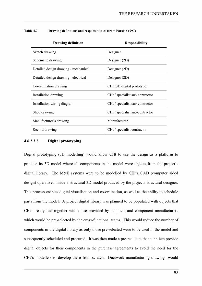
THE RESEARCH UNDERTAKEN
83
Table 4.7 Drawing definitions and responsibilities (from Parsloe 1997)
Drawing definition Responsibility
Sketch drawing Designer
Schematic drawing Designer (2D)
Detailed design drawing - mechanical Designer (2D)
Detailed design drawing - electrical Designer (2D)
Co-ordination drawing CHt (3D digital prototype)
Installation drawing CHt / specialist sub-contractor
Installation wiring diagram CHt / specialist sub-contractor
Shop drawing CHt / specialist sub-contractor
Manufacturer’s drawing Manufacturer
Record drawing CHt / specialist contractor
4.6.2.3.2 Digital prototyping
Digital prototyping (3D modelling) would allow CHt to use the design as a platform to
produce its 3D model where all components in the model were objects from the project’s
digital library. The M&E systems were to be modelled by CHt’s CAD (computer aided
design) operatives inside a structural 3D model produced by the projects structural designer.
This process enables digital visualisation and co-ordination, as well as the ability to schedule
parts from the model. A project digital library was planned to be populated with objects that
CHt already had together with those provided by suppliers and component manufacturers
which would be pre-selected by the cross-functional teams. This would reduce the number of
components in the digital library as only those pre-selected were to be used in the model and
subsequently scheduled and procured. It was then made a pre-requisite that suppliers provide
digital objects for their components in the purchase agreements to avoid the need for the
CHt’s modellers to develop these from scratch. Ductwork manufacturing drawings would
THE RESEARCH UNDERTAKEN
84
also be produced from the model, allowing direct transmission of data to CHt’s
manufacturer’s CAM (computer aided manufacturing) machinery. This was to avoid the
waste of reproducing manufacturing drawings from traditional 2D layouts. Modular
assemblies were planned to be objects within the model which in turn would have individual
manufacturing drawings associated with them. The model would generate single service
drawings, each being a layer from the parent model which would be coordinated and free of
clashes (after a clash detection process). Actual drawings required would then be printed
from the model into paper-space (a conventional 2D drawing) for use in the manufacturing
and construction processes as required. A collaborative web-based document and information
management system was then to be deployed on the project which would manage the flow of
information from the project to the supply chain and those requiring information.
4.6.2.4 Procurement
Procurement was then to be undertaken in accordance with CHt’s policies and procedures
using national framework suppliers and sub-contractors already in CHt’s supply chain.
According to the author this isn’t a Lean procurement practice because it involves non-
relational contracting and competitive tendering, which is not a Lean Construction ideal. As
Colledge (2005) reports, criticism of the (construction) industry as a whole in the past has
focused on the inability of contracting stakeholders to engage co-operatively in the delivery of
the client’s objectives and an apparent inability to deliver on time cost and quality. It would
appear, Colledge continues, that adversarial contracting approaches and the pursuit of
individual company gain has resulted in a less efficient industry and lower levels of
productivity and innovation (also reported in Latham 1994, and DETR 1998). The author
could not influence this approach as it is driven by corporate policy from the centre of CHt
and therefore was not part of the development of the Construction System. However, a Lean
THE RESEARCH UNDERTAKEN
85
Construction philosophy was written into the specialist sub-contract terms and conditions that
sub-contractors would have to abide by. These particular contract clauses included:
• What is Lean Construction?
• Workflow Planning (Last Planner System of Production Control);
• Week-Beat Programming – Creating Workflow;
• Workplace Organisation; Tooling and Access Equipment;
• Team Working;
• Continuous Improvement Practices.
All of these were to be pre-requisites for sub-contract award along with other usual contract
clauses particular to the case study project. The purpose of these Lean Construction pre-
requisites was to ensure, as far as possible, that sub-contractors and suppliers engaged with
the project’s Lean method of working within the contractual framework allowed by CHt.
These specialist sub-contractors, when engaged, would also form part of the cross-functional
teams to collaborate where necessary in the Construction System development process.
For labour procurement at that time, CHt predominantly operated a self-delivery model
meaning that most installation work would be undertaken by its own workers or labour-only
sub-contractors with just specialist work undertaken by sub-contractors. By utilising the
direct labour approach it was perceived that CHt would have greater control over the labour
element of the project than it would with sub-contract labour, in other words “you can’t
control what you don’t control”. Specialists would include pneumatic tube conveyor system;
thermal insulation; nurse call systems; fire alarm systems; refrigeration systems and medical
gas systems.
THE RESEARCH UNDERTAKEN
86
4.6.2.5 Component manufacture
This particular phase of the research process resulted in the third paper submitted for the
Engineering Doctorate and is described in Court et al. (2009). This paper (paper 3) is
contained in appendix C, and is published in the American Society of Civil Engineers
publication, the Practice Periodical on Structural Design and Construction (May 2009). This
paper describes the design of the modular assembly and postponement components of the
Construction System. The key elements reported in this paper are the logistics strategy;
installation sequencing; approach to modular assembly and postponement for construction
zones; construction zone and plantroom modules (type A parts); construction zone component
flows (type B and C parts) and labour and associated cost forecast (expected benefits of the
System). A further research paper describes the overall function of the site operations
component (final assembly unit) of the Construction System (Court et al. 2007). This paper is
not included in this thesis but is a part of the development of the overall System. The paper
covers an important area of research within the IGLC community, which is the theory of
Construction Physics. The paper was best in section when presented at the IGLC 15
conference in July 2007, Michigan, USA in the Championship: Production System Design.
Before the commencement of component selection, a site-wide logistics strategy had to be set.
The component manufacture methodology had to fit within a logistics strategy to ensure
synchronisation of component flows into site and the Week-Beat method of operation.
4.6.2.5.1 Logistics Strategy
The purpose of this logistics strategy was to communicate to the wider team and supply chain
members the logistics intent. It was purposefully designed to reduce the waste traditionally
seen in construction processes, i.e. inventory is a waste (and gets damaged lying around site);
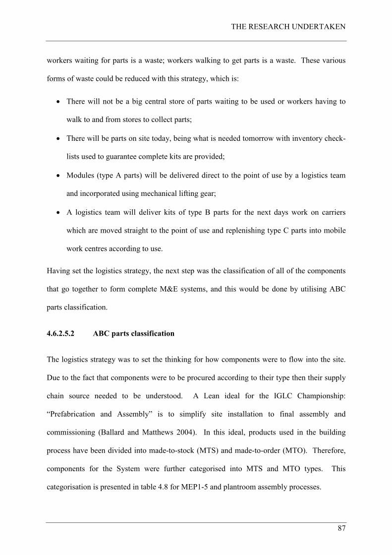
THE RESEARCH UNDERTAKEN
87
workers waiting for parts is a waste; workers walking to get parts is a waste. These various
forms of waste could be reduced with this strategy, which is:
• There will not be a big central store of parts waiting to be used or workers having to
walk to and from stores to collect parts;
• There will be parts on site today, being what is needed tomorrow with inventory check-
lists used to guarantee complete kits are provided;
• Modules (type A parts) will be delivered direct to the point of use by a logistics team
and incorporated using mechanical lifting gear;
• A logistics team will deliver kits of type B parts for the next days work on carriers
which are moved straight to the point of use and replenishing type C parts into mobile
work centres according to use.
Having set the logistics strategy, the next step was the classification of all of the components
that go together to form complete M&E systems, and this would be done by utilising ABC
parts classification.
4.6.2.5.2 ABC parts classification
The logistics strategy was to set the thinking for how components were to flow into the site.
Due to the fact that components were to be procured according to their type then their supply
chain source needed to be understood. A Lean ideal for the IGLC Championship:
“Prefabrication and Assembly” is to simplify site installation to final assembly and
commissioning (Ballard and Matthews 2004). In this ideal, products used in the building
process have been divided into made-to-stock (MTS) and made-to-order (MTO). Therefore,
components for the System were further categorised into MTS and MTO types. This
categorisation is presented in table 4.8 for MEP1-5 and plantroom assembly processes.
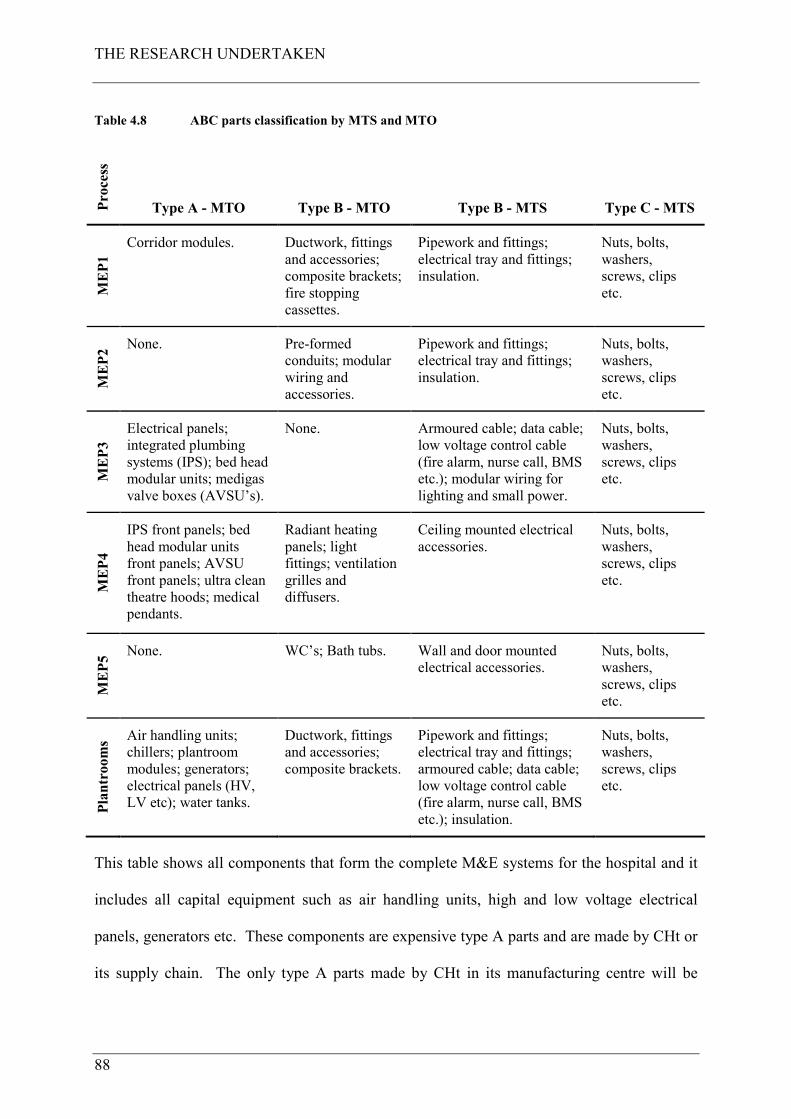
THE RESEARCH UNDERTAKEN
88
Table 4.8 ABC parts classification by MTS and MTO
Process
Type A - MTO Type B - MTO Type B - MTS Type C - MTS
MEP1
Corridor modules. Ductwork, fittings
and accessories;
composite brackets;
fire stopping
cassettes.
Pipework and fittings;
electrical tray and fittings;
insulation.
Nuts, bolts,
washers,
screws, clips
etc.
MEP2 None. Pre-formed
conduits; modular
wiring and
accessories.
Pipework and fittings;
electrical tray and fittings;
insulation.
Nuts, bolts,
washers,
screws, clips
etc.
MEP3
Electrical panels;
integrated plumbing
systems (IPS); bed head
modular units; medigas
valve boxes (AVSU’s).
None. Armoured cable; data cable;
low voltage control cable
(fire alarm, nurse call, BMS
etc.); modular wiring for
lighting and small power.
Nuts, bolts,
washers,
screws, clips
etc.
MEP4
IPS front panels; bed
head modular units
front panels; AVSU
front panels; ultra clean
theatre hoods; medical
pendants.
Radiant heating
panels; light
fittings; ventilation
grilles and
diffusers.
Ceiling mounted electrical
accessories.
Nuts, bolts,
washers,
screws, clips
etc.
MEP5 None. WC’s; Bath tubs. Wall and door mounted
electrical accessories.
Nuts, bolts,
washers,
screws, clips
etc.
Plantrooms
Air handling units;
chillers; plantroom
modules; generators;
electrical panels (HV,
LV etc); water tanks.
Ductwork, fittings
and accessories;
composite brackets.
Pipework and fittings;
electrical tray and fittings;
armoured cable; data cable;
low voltage control cable
(fire alarm, nurse call, BMS
etc.); insulation.
Nuts, bolts,
washers,
screws, clips
etc.
This table shows all components that form the complete M&E systems for the hospital and it
includes all capital equipment such as air handling units, high and low voltage electrical
panels, generators etc. These components are expensive type A parts and are made by CHt or
its supply chain. The only type A parts made by CHt in its manufacturing centre will be
THE RESEARCH UNDERTAKEN
89
corridor modules29 (MEP1 type A parts) and plantroom modules (plantroom type A parts).
Traditionally the components within these modules are fitted on site by operatives engaged in
site cutting, drilling and assembly work and elevation of parts into final position, as has been
previously described in the literature search findings for the current state of the research
problem (step 2).
All components are to be pre-selected by the team and where required are also to be supplied
in 3D object format for inclusion in the project’s 3D model. This allows the number of
supplier’s components used in the System to be reduced and a project object library to be
compiled from which components are selected and procured.
The strategy is essentially a Just-In-Time (JIT) system and according to Forza (1996), a
production system which culminates with JIT is very efficient if everything runs perfectly but
is extremely fragile if there is any kind of problem whatsoever. Further, and in order to be
able to function in a Lean system, all the resources being used in the production process have
to be foreseeable and reliable. The Construction System had this potential to be fragile as it
was not, at that time, embedded into CHt’s operations or tried and tested (because it is a case
study undergoing trial implementation) therefore, component flows into the project had to be
foreseeable and reliable in order for the Construction System to work as planned. In Hopp
and Spearman (2001), safety stock and safety lead times can be used as protection against
these problems. Safety stock should be used to protect against uncertainties in production and
demand quantities, while safety lead time should be used to protect against uncertainties in
production and demand timing. These countermeasures were built-into the Construction
29 Riser modules were not able to be supplied for the case study project due to certain design issues that
are not reported in this research project. These did feature, however, in later phases of the project as the
design issues were overcome by the team.
THE RESEARCH UNDERTAKEN
90
System and resource capacity buffers were built into the site operations component. This was
done by planning each week activity into four days of the week which sizes the team to carry
out the work required for the designated activity. This provided a one day capacity each week
to buffer against any unplanned event that may have occurred. If the work was completed in
the planned duration the team would then be able to clear backlog items or make ready to
move to the next construction zone in the sequence. Figure 4.25 presents the component
flows into the site by MTO and MTS suppliers, showing safety lead time and safety stock
buffers and their location in the supply chain.
Construction zone and plantroom assembly processes
Site (final assembly unit)
Type A parts (MTO)
Type B parts (MTO)
MTO manufacturingunits
Call-off
Call-off
Modules
Suppliers
Replenishment
Replenishment
Call-off
Call-off
MTO supply chain
Suppliers
supply
Fast kit
Type A parts (MTO)
Type B parts (MTO)
MTO manufacturingunits
Call-off
Call-off
Modules
Suppliers
Replenishment
Replenishment
Call-off
Call-off
MTO supply chain
Suppliers
supply
Fast kit
Type A parts (MTO)
Type B parts (MTO)
MTO manufacturingunits
Call-off
Call-off
Modules
Suppliers
Replenishment
Replenishment
Call-off
Call-off
MTO supply chain
Suppliers
supply
Fast kit
Type C parts (MTS)
Type B parts (MTS)
CentralWarehouse
Central Warehouse
MTS local supply branches
MTS central supply warehouses
Call-off
Replenishment
Kanban
Replenishment
Replenishment
Call-off
Call-off
Fast kit
supply
Type C parts (MTS)
Type B parts (MTS)
CentralWarehouse
Central Warehouse
MTS local supply branches
MTS central supply warehouses
Call-off
Replenishment
Kanban
Replenishment
Replenishment
Call-off
Call-off
Fast kit
supply
MTO - Safety lead-timeMTO - Safety lead-time MTS - Safety stockMTS - Safety stock
Figure 4.25 MTO and MTS component flows into site
Safety lead time in the System had to be provided in the supply chain for MTO type A and B
parts. MTO type A modules, given their size and complexity, would be required to be
delivered directly to the point of use (not postponed), and their lead time was to be
incorporated into the master schedule. A safety buffer of at least two weeks would then built-
in, dependant upon the module type, to protect against any disruption to production and site

THE RESEARCH UNDERTAKEN
91
demand. MTO type B components have a lower lead time than modules and again safety lead
time for these was also to be built into the master schedule.
Safety stock in the System was planned to be provided both on site and in the supply chain for
MTS type B and C parts. These parts were to be purchased from national framework
suppliers and held in stock at a local branch. The kits to be provided to site were to be
delivered ‘today’ for use ‘tomorrow’ giving a one day stock buffer on site. As described
previously, individual works within a construction zone is to take one week to complete in the
Week-Beat cycle and supplier’s agreements would be to keep two zones of parts in stock at
the local branch. Replenishment was to be signalled when parts for a zone are depleted,
giving a one week safety stock buffer in the System, but offsite. Site replenishment from the
local branch would signal replenishment from the central warehouse to the local branch which
would replenish it with parts for a zone every week. The central warehouse would operate a
12 week stock-turn giving an 11 week safety stock buffer further back in the System; this was
to rely upon global project quantities being advised by the project to the supply chain which
had to be done. All components were planned to be delivered to site by the supply chain to
then be handled from the point of delivery to the point of use by a site logistics team operated
by CHt.
4.6.2.5.3 Modular assembly - construction zone and plantroom modules (type A
parts)
The corridor modules were to be assembled in CHt’s manufacturing centre (with its own
labour), to then be transported to site in batches of four on assembly, transportation and
installation frames (ATIF’s). These are then to be lifted with mechanical hoists and bolted to
cast-in unistrut inserts running in tram-lines along corridor positions in the concrete soffit.
The ATIF is then returned to the manufacturing centre for re-use. Each construction zone has
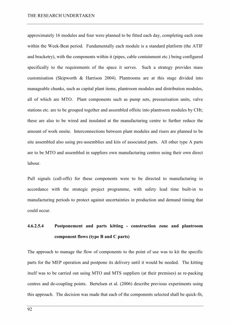
THE RESEARCH UNDERTAKEN
92
approximately 16 modules and four were planned to be fitted each day, completing each zone
within the Week-Beat period. Fundamentally each module is a standard platform (the ATIF
and bracketry), with the components within it (pipes, cable containment etc.) being configured
specifically to the requirements of the space it serves. Such a strategy provides mass
customisation (Skipworth & Harrison 2004). Plantrooms are at this stage divided into
manageable chunks, such as capital plant items, plantroom modules and distribution modules,
all of which are MTO. Plant components such as pump sets, pressurisation units, valve
stations etc. are to be grouped together and assembled offsite into plantroom modules by CHt;
these are also to be wired and insulated at the manufacturing centre to further reduce the
amount of work onsite. Interconnections between plant modules and risers are planned to be
site assembled also using pre-assemblies and kits of associated parts. All other type A parts
are to be MTO and assembled in suppliers own manufacturing centres using their own direct
labour.
Pull signals (call-offs) for these components were to be directed to manufacturing in
accordance with the strategic project programme, with safety lead time built-in to
manufacturing periods to protect against uncertainties in production and demand timing that
could occur.
4.6.2.5.4 Postponement and parts kitting - construction zone and plantroom
component flows (type B and C parts)
The approach to manage the flow of components to the point of use was to kit the specific
parts for the MEP operation and postpone its delivery until it would be needed. The kitting
itself was to be carried out using MTO and MTS suppliers (at their premises) as re-packing
centres and de-coupling points. Bertelsen et al. (2006) describe previous experiments using
this approach. The decision was made that each of the components selected shall be quick-fit,
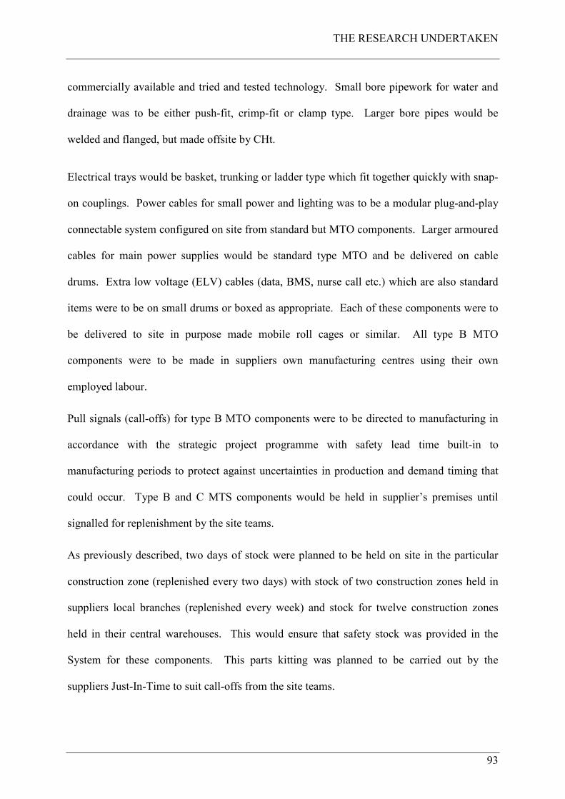
THE RESEARCH UNDERTAKEN
93
commercially available and tried and tested technology. Small bore pipework for water and
drainage was to be either push-fit, crimp-fit or clamp type. Larger bore pipes would be
welded and flanged, but made offsite by CHt.
Electrical trays would be basket, trunking or ladder type which fit together quickly with snap-
on couplings. Power cables for small power and lighting was to be a modular plug-and-play
connectable system configured on site from standard but MTO components. Larger armoured
cables for main power supplies would be standard type MTO and be delivered on cable
drums. Extra low voltage (ELV) cables (data, BMS, nurse call etc.) which are also standard
items were to be on small drums or boxed as appropriate. Each of these components were to
be delivered to site in purpose made mobile roll cages or similar. All type B MTO
components were to be made in suppliers own manufacturing centres using their own
employed labour.
Pull signals (call-offs) for type B MTO components were to be directed to manufacturing in
accordance with the strategic project programme with safety lead time built-in to
manufacturing periods to protect against uncertainties in production and demand timing that
could occur. Type B and C MTS components would be held in supplier’s premises until
signalled for replenishment by the site teams.
As previously described, two days of stock were planned to be held on site in the particular
construction zone (replenished every two days) with stock of two construction zones held in
suppliers local branches (replenished every week) and stock for twelve construction zones
held in their central warehouses. This would ensure that safety stock was provided in the
System for these components. This parts kitting was planned to be carried out by the
suppliers Just-In-Time to suit call-offs from the site teams.

THE RESEARCH UNDERTAKEN
94
4.6.2.6 Onsite assembly
4.6.2.6.1 Inbound and outbound logistics
As has been described previously all components once delivered to site would be handled
directly to the point of use by a logistics team. This team, to be headed by a team leader,
would then manage inbound and outbound logistics for all M&E work activities. Inbound
logistics was to include offloading deliveries, co-ordinated with other non M&E deliveries for
distribution to the point of use. Outbound logistics was to include the removal of all empty
stillages and ATIF frames and re-loading these on back-hauls to the relevant supplier /
manufacturer for replenishment. Outbound logistics would also include managing physical
waste out of the workplace and for segregation into central skips for onward disposal.
4.6.2.6.2 Workplace organisation
During the course of the design of the Construction System further data was collected for the
design of trade team specific mobile work cells. This was conducted in collaborative
planning sessions with representatives from electrical workers, mechanical pipe workers and
duct workers. The parameters set were to ensure that each trade team would have a complete
set of equipment including appropriate personnel protective equipment (PPE); tools; lighting;
access equipment; workbenches; parts trolleys; walkie-talkies and everything that will be
needed for each individual trade team. This process produced designs and led to the
manufacture of workplace equipment for each of the sub-process trade teams and included
(but was not limited to):
• Information and drawing boards (example in figure 4.26);
• Mobile workbenches (example in figure 4.27);
• Mobile parts storage units and stillages (examples in figure 4.28, 4.29);
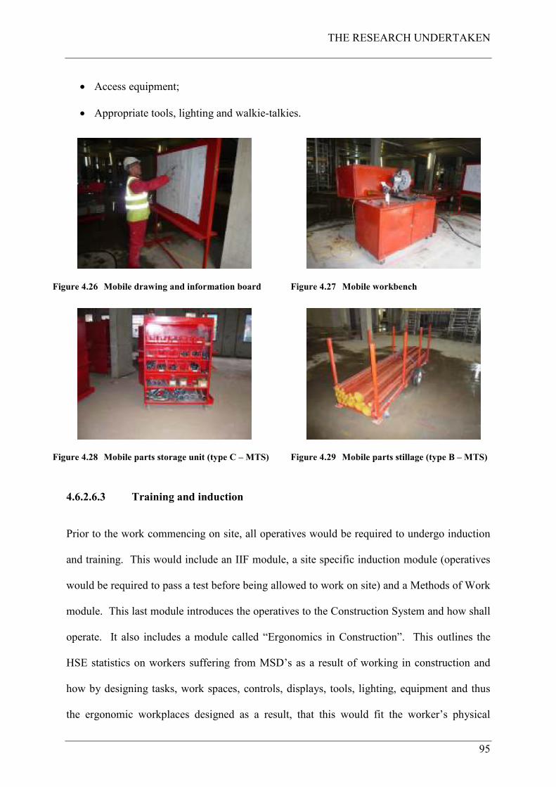
THE RESEARCH UNDERTAKEN
95
• Access equipment;
• Appropriate tools, lighting and walkie-talkies.
Figure 4.26 Mobile drawing and information board
Figure 4.27 Mobile workbench
Figure 4.28 Mobile parts storage unit (type C – MTS)
Figure 4.29 Mobile parts stillage (type B – MTS)
4.6.2.6.3 Training and induction
Prior to the work commencing on site, all operatives would be required to undergo induction
and training. This would include an IIF module, a site specific induction module (operatives
would be required to pass a test before being allowed to work on site) and a Methods of Work
module. This last module introduces the operatives to the Construction System and how shall
operate. It also includes a module called “Ergonomics in Construction”. This outlines the
HSE statistics on workers suffering from MSD’s as a result of working in construction and
how by designing tasks, work spaces, controls, displays, tools, lighting, equipment and thus
the ergonomic workplaces designed as a result, that this would fit the worker’s physical
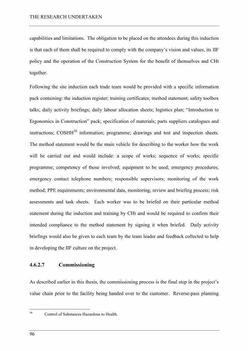
THE RESEARCH UNDERTAKEN
96
capabilities and limitations. The obligation to be placed on the attendees during this induction
is that each of them shall be required to comply with the company’s vision and values, its IIF
policy and the operation of the Construction System for the benefit of themselves and CHt
together.
Following the site induction each trade team would be provided with a specific information
pack containing: the induction register; training certificates; method statement; safety toolbox
talks; daily activity briefings; daily labour allocation sheets; logistics plan; “Introduction to
Ergonomics in Construction” pack; specification of materials; parts suppliers catalogues and
instructions; COSHH30 information; programme; drawings and test and inspection sheets.
The method statement would be the main vehicle for describing to the worker how the work
will be carried out and would include: a scope of works; sequence of works; specific
programme; competency of those involved; equipment to be used; emergency procedures;
emergency contact telephone numbers; responsible supervisors; monitoring of the work
method; PPE requirements; environmental data, monitoring, review and briefing process; risk
assessments and task sheets. Each worker was to be briefed on their particular method
statement during the induction and training by CHt and would be required to confirm their
intended compliance to the method statement by signing it when briefed. Daily activity
briefings would also be given to each team by the team leader and feedback collected to help
in developing the IIF culture on the project.
4.6.2.7 Commissioning
As described earlier in this thesis, the commissioning process is the final step in the project’s
value chain prior to the facility being handed over to the customer. Reverse-pass planning
30 Control of Substances Hazardous to Health.
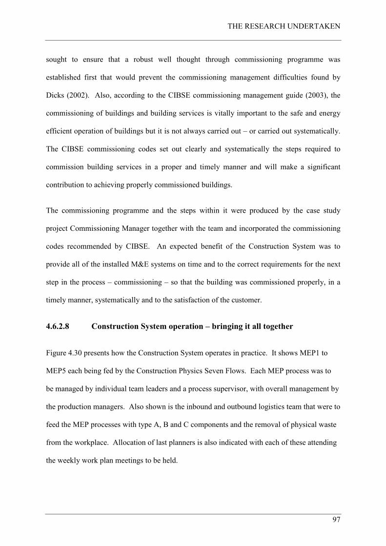
THE RESEARCH UNDERTAKEN
97
sought to ensure that a robust well thought through commissioning programme was
established first that would prevent the commissioning management difficulties found by
Dicks (2002). Also, according to the CIBSE commissioning management guide (2003), the
commissioning of buildings and building services is vitally important to the safe and energy
efficient operation of buildings but it is not always carried out – or carried out systematically.
The CIBSE commissioning codes set out clearly and systematically the steps required to
commission building services in a proper and timely manner and will make a significant
contribution to achieving properly commissioned buildings.
The commissioning programme and the steps within it were produced by the case study
project Commissioning Manager together with the team and incorporated the commissioning
codes recommended by CIBSE. An expected benefit of the Construction System was to
provide all of the installed M&E systems on time and to the correct requirements for the next
step in the process – commissioning – so that the building was commissioned properly, in a
timely manner, systematically and to the satisfaction of the customer.
4.6.2.8 Construction System operation – bringing it all together
Figure 4.30 presents how the Construction System operates in practice. It shows MEP1 to
MEP5 each being fed by the Construction Physics Seven Flows. Each MEP process was to
be managed by individual team leaders and a process supervisor, with overall management by
the production managers. Also shown is the inbound and outbound logistics team that were to
feed the MEP processes with type A, B and C components and the removal of physical waste
from the workplace. Allocation of last planners is also indicated with each of these attending
the weekly work plan meetings to be held.
THE RESEARCH UNDERTAKEN
98
F2 F3 F4 F5 F6 F7
Outbound logistics
Inbound logistics
Logistics supervisor (LP)
Production manager/s (LPF)
Process supervisor (LP)
Team leaders (LP)WB
LPF: Last planner™ facilitator
MEP 1
MEP: Mechanical and electrical process
F1
F1: Flow of informationF2: Flow of materialsF3: Flow of previous workF4: Flow of spaceF5: Flow of crewsF6: Flow of equipmentF7: External conditions
Key:
WB: Working backlogLP: Last planner™
WF
/MR WF/MR: Working front-log/make-ready
WB
Process supervisor (LP)
MEP 3
Team leaders (LP)WBWB
Process supervisor (LP)
MEP 3
Team leaders (LP)
Process supervisor (LP)
MEP 3
Team leaders (LP) WF
/MR
WF
/MR
Process supervisor (LP)
MEP 4
Team leaders (LP)WB
Process supervisor (LP)
MEP 4
Team leaders (LP)
Process supervisor (LP)
MEP 4
Team leaders (LP)WBWB WF
/MR
WF
/MR
Process supervisor (LP)
MEP 5
Team leaders (LP)WB
Process supervisor (LP)
MEP 5
Team leaders (LP)
Process supervisor (LP)
MEP 5
Team leaders (LP)WBWB WF
/MR
WF
/MR
Process supervisor (LP)
MEP 2
Team leaders (LP)WB
Process supervisor (LP)
MEP 2
Team leaders (LP)WB
Process supervisor (LP)
MEP 2
Team leaders (LP)
Process supervisor (LP)
MEP 2
Team leaders (LP)WBWB WF
/MR
WF
/MR
Figure 4.30 Construction System operation – bringing it all together
THE RESEARCH UNDERTAKEN
99
4.6.2.9 Summary of step 5
This section has described the selection of the case study project and the process of turning
the theory of the Construction System into practice with real meaningful methods that can
work when implemented. The next step in the research process is the setting of realistic
objectives and measurement of success for implementation.
4.7 STEP 6: SETTING OF REALISTIC OBJECTIVES AND
MEASUREMENT OF SUCCESS FOR IMPLEMENTATION
The aim for the performance of the Construction System is set out in chapter 2 of this thesis
which is to improve site operations, making them safer for the worker and to improve
productivity as a countermeasure to the problems in UK construction that face CHt. This
therefore must be measureable in terms of health, safety and productivity outcomes to gauge
if the implementation of the Construction System has been successful. This step in the
research process continued the action research method and used a large scale experimental
study expanding upon the pilot study reported in Court et al. (2005). In this study, a project
was chosen as the experiment, and a hypothesis, which is a statement about cause and effect
that can be tested, was set as follows:
“Lean as an antidote to labour cost escalation on complex mechanical and electrical
projects”.
Labour was the independent variable to be manipulated in that experiment, and the outturn
cost of labour was the dependent variable, which was observed as the outcome of the
experiment. In order to manipulate the independent variable (labour), Lean interventions
were designed and applied to the project. These were: standardisation of components;
THE RESEARCH UNDERTAKEN
100
standardised work sequencing; mobile work cell and ergonomic access equipment. In this
larger, case study experiment, labour would still be the independent variable to be
manipulated by the application of the Construction System. The dependent variable would be
the health, safety and productivity outcomes of the experiment that could be measured. The
laboratory in which to conduct the experiment was to be the Maternity and Oncology case
study project during a sample period, this being the planned onsite assembly time for the
M&E works across all construction zones and plantrooms.
4.7.1 Measurement of productivity outcomes
For productivity and labour cost and utilisation, targets were set to decrease the amount of
labour required to carry out the work and to facilitate improved effectiveness and productive
work for those that are required onsite. When combining offsite modular assembly and
postponement with the Lean site operations component of the Construction System and then
projecting the labour required performing all planned operations, a target of 35% less onsite
labour was set. This target was derived from a comparison of calculated estimates of labour
times between conducting the work using traditional methods and by using the Construction
System as described in this thesis. For all MEP processes, including plantrooms, the
traditional method is estimated at 202,800 hours, with the construction method estimated at
131,84031 hours. This equates to a difference of 70,960
32 hours between the two methods
which is the 35% reduction in onsite hours. Also, because of the simplification of the
assembly process, a lower ratio of skilled to semi-skilled operatives will be required, which
31 Previously reported as 131,040 hours in Court et al. (2009) and now corrected to 131,840 hours (authors
typing error).
32 Previously reported as 71,960 hours in Court et al. (2009) and now corrected to 70,960 hours (authors
typing error).
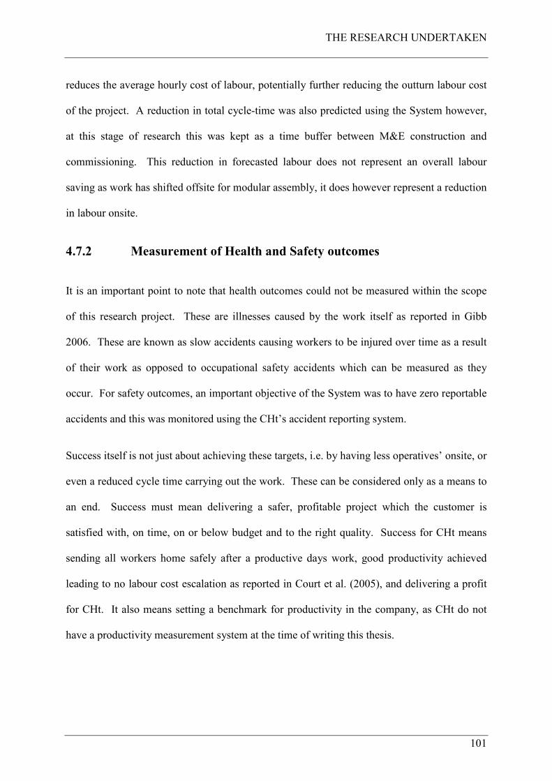
THE RESEARCH UNDERTAKEN
101
reduces the average hourly cost of labour, potentially further reducing the outturn labour cost
of the project. A reduction in total cycle-time was also predicted using the System however,
at this stage of research this was kept as a time buffer between M&E construction and
commissioning. This reduction in forecasted labour does not represent an overall labour
saving as work has shifted offsite for modular assembly, it does however represent a reduction
in labour onsite.
4.7.2 Measurement of Health and Safety outcomes
It is an important point to note that health outcomes could not be measured within the scope
of this research project. These are illnesses caused by the work itself as reported in Gibb
2006. These are known as slow accidents causing workers to be injured over time as a result
of their work as opposed to occupational safety accidents which can be measured as they
occur. For safety outcomes, an important objective of the System was to have zero reportable
accidents and this was monitored using the CHt’s accident reporting system.
Success itself is not just about achieving these targets, i.e. by having less operatives’ onsite, or
even a reduced cycle time carrying out the work. These can be considered only as a means to
an end. Success must mean delivering a safer, profitable project which the customer is
satisfied with, on time, on or below budget and to the right quality. Success for CHt means
sending all workers home safely after a productive days work, good productivity achieved
leading to no labour cost escalation as reported in Court et al. (2005), and delivering a profit
for CHt. It also means setting a benchmark for productivity in the company, as CHt do not
have a productivity measurement system at the time of writing this thesis.
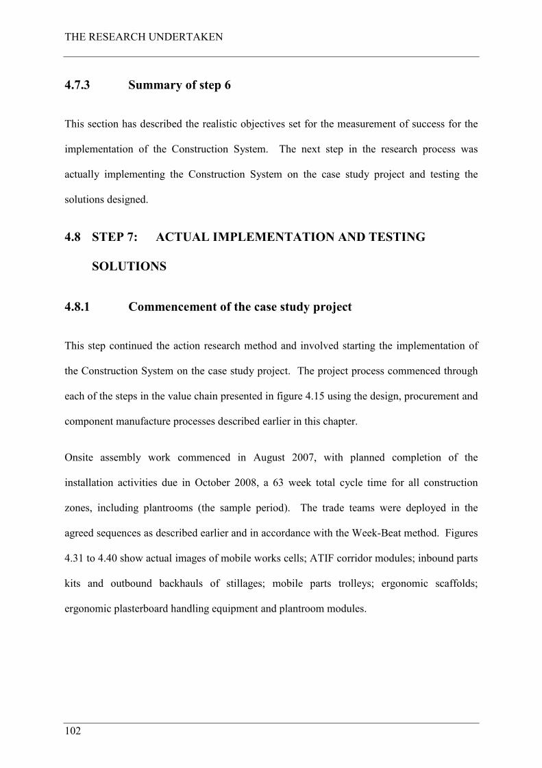
THE RESEARCH UNDERTAKEN
102
4.7.3 Summary of step 6
This section has described the realistic objectives set for the measurement of success for the
implementation of the Construction System. The next step in the research process was
actually implementing the Construction System on the case study project and testing the
solutions designed.
4.8 STEP 7: ACTUAL IMPLEMENTATION AND TESTING
SOLUTIONS
4.8.1 Commencement of the case study project
This step continued the action research method and involved starting the implementation of
the Construction System on the case study project. The project process commenced through
each of the steps in the value chain presented in figure 4.15 using the design, procurement and
component manufacture processes described earlier in this chapter.
Onsite assembly work commenced in August 2007, with planned completion of the
installation activities due in October 2008, a 63 week total cycle time for all construction
zones, including plantrooms (the sample period). The trade teams were deployed in the
agreed sequences as described earlier and in accordance with the Week-Beat method. Figures
4.31 to 4.40 show actual images of mobile works cells; ATIF corridor modules; inbound parts
kits and outbound backhauls of stillages; mobile parts trolleys; ergonomic scaffolds;
ergonomic plasterboard handling equipment and plantroom modules.
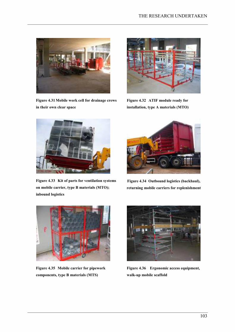
THE RESEARCH UNDERTAKEN
103
Figure 4.31 Mobile work cell for drainage crews
in their own clear space
Figure 4.32 ATIF module ready for
installation, type A materials (MTO)
Figure 4.33 Kit of parts for ventilation systems
on mobile carrier, type B materials (MTO);
inbound logistics
Figure 4.34 Outbound logistics (backhaul),
returning mobile carriers for replenishment
Figure 4.35 Mobile carrier for pipework
components, type B materials (MTS)
Figure 4.36 Ergonomic access equipment,
walk-up mobile scaffold
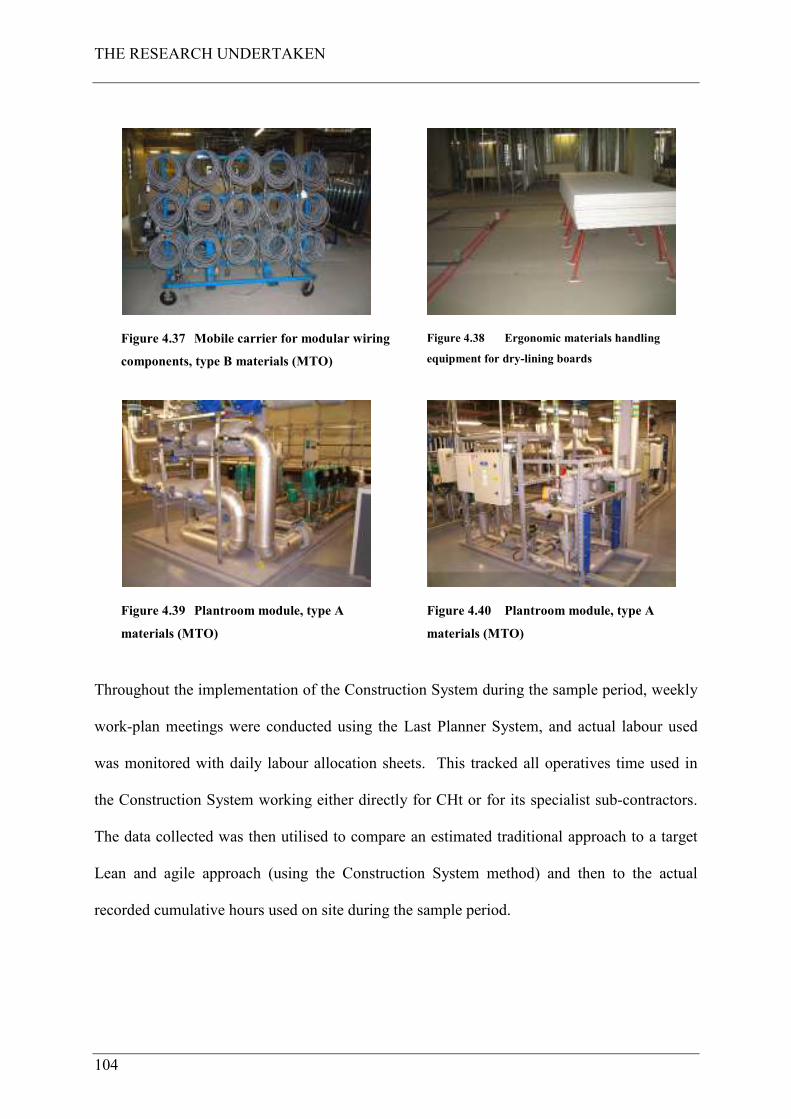
THE RESEARCH UNDERTAKEN
104
Figure 4.37 Mobile carrier for modular wiring
components, type B materials (MTO)
Figure 4.38 Ergonomic materials handling
equipment for dry-lining boards
Figure 4.39 Plantroom module, type A
materials (MTO)
Figure 4.40 Plantroom module, type A
materials (MTO)
Throughout the implementation of the Construction System during the sample period, weekly
work-plan meetings were conducted using the Last Planner System, and actual labour used
was monitored with daily labour allocation sheets. This tracked all operatives time used in
the Construction System working either directly for CHt or for its specialist sub-contractors.
The data collected was then utilised to compare an estimated traditional approach to a target
Lean and agile approach (using the Construction System method) and then to the actual
recorded cumulative hours used on site during the sample period.
THE RESEARCH UNDERTAKEN
105
4.8.2 Summary of step 7
Step 7 of the research process began the implementation of the Construction System on the
case study project through each of the construction zones and plantrooms. The next step was
monitoring the System in use and gathering data in order to assess findings and results
emerging during the implementation.
4.9 STEP 8: FIRST RUN STUDY WITH RESULTS EMERGING
4.9.1 Progress in the sample period
All M&E construction zone processes (MEP1-5) and plantrooms were complete at the end of
October 2008 (week 66), with the exception of the completion of major customer variations to
the Oncology department and working backlog items33. These customer variations resulted in
approximately 60% of this department (2 construction zones) having to be remodelled.
During the sample period 80% of electrical testing was complete; 80% of water systems
pressure testing was complete; 50% of ELV system testing was complete (building
management systems, fire alarms etc.); 90% of voice and data system testing was complete
and clean commissioning commenced (air and water system balancing). High voltage power-
on was achieved June 2008, and water-on to the building was achieved August 2008. Hand-
over to the customer occurred in March 2009 for the Maternity department and June 2009 for
the Oncology department, both on time and to budget. During this sample period, certain
findings emerged relating to productivity and labour cost, and Health and Safety, which are
now reported.
33 Working backlog is defined here as any minor incomplete works and rework items (such as snagging,
missed items of work etc.).
THE RESEARCH UNDERTAKEN
106
4.9.2 Findings emerging from the sample period
The findings emerging from the sample period have fallen into two sets and are reported in
Court et al. 2008 (paper 4 contained in appendix D), and Court et al. 2009a (paper 5 contained
in appendix E).
4.9.2.1 Productivity and labour cost findings
Productivity and labour cost findings emerging from implementation have fallen into two
sets. The first set was the results and analysis of the benefits from the use of corridor modules
in lieu of a traditional installation method. This sub-process within MEP1, the installation of
corridor modules made offsite, is reported in Court et al. (2008) and is contained in appendix
D. This paper (paper 4) was presented at the IGLC 16 conference in Manchester, UK, in the
Championship: Prefabrication, Assembly and Open Building. This paper reports on the
findings from this case study using the IMMPREST34 toolkit. Pasquire et al. (2005) describe
the IMMPREST toolkit as a tool for assessing the benefits derived from the use of modular
offsite assembly (hereafter known as S&P35) against what would have been traditional
installation methods had this been used. The benefits were classified into six categories: cost;
time; quality; health and safety; sustainability and site benefits. The traditional option
described in the assessment is: “site installation of corridor mechanical and electrical services
using traditional methods” (known hereafter as traditional) and the S&P option described is:
“modularising corridor services using the ATIF method”. The paper reports that 1,568 actual
onsite hours were used elevating and connecting together a total of 196 ATIF modules in
comparison to 22,320 hours estimated using traditional methods, which would have required
34 Interactive Model for Measuring Preassembly and Standardisation in construction.
35 S&P meaning standardisation and preassembly as an IMMPREST term.
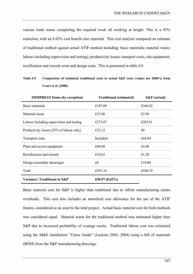
THE RESEARCH UNDERTAKEN
107
various trade teams completing the required work all working at height. This is a 93%
reduction, with an 8.62% cost benefit also reported. This cost analysis compared an estimate
of traditional method against actual ATIF method including: basic materials; material waste;
labour (including supervision and testing); productivity losses; transport costs; site equipment;
rectification and rework costs and design costs. This is presented in table 4.9.
Table 4.9 Comparison of estimated traditional costs to actual S&P costs (values are £000’s) from
Court et al. (2008)
IMMPREST Items (by exception) Traditional (estimated) S&P (actual)
Basic materials £197.09 £260.42
Material waste £15.86 £3.96
Labour including supervision and testing £273.67 £205.81
Productivity losses (25% of labour only) £53.12 £0
Transport costs Included £44.84
Plant and access equipment £40.80 £4.08
Rectification and rework £10.62 £1.28
Design (assembly drawings) £0 £19.80
Total £591.16 £540.19
Variance: Traditional to S&P £50.97 (8.62%)
Basic material cost for S&P is higher than traditional due to offsite manufacturing centre
overheads. This cost also includes an amortised cost allowance for the use of the ATIF
frames, considered as an asset to the total project. Actual basic material cost for both methods
was considered equal. Material waste for the traditional method was estimated higher than
S&P due to increased probability of wastage onsite. Traditional labour cost was estimated
using the M&E installation “Times Guide” (Luckins 2003, 2004) using a bill of materials
(BOM) from the S&P manufacturing drawings.
THE RESEARCH UNDERTAKEN
108
The Luckins “Times Guides” assume average times under average conditions and installing
good quality materials with good quality trained workers. No other site difficulty factors were
included. S&P labour cost is the actual cost incurred and includes manufacturing centre
overheads and the onsite cost to install ATIF modules and connect them together.
Productivity losses means a cost factor estimate of the productivity losses possible between
the different methods, including weather, stoppages, damage, theft and interferences etc. The
estimated cost of this was assessed as 25% of traditional installation labour only to
demonstrate this variable. As can be seen, the value of this variable provides the benefit
assessed between the different methods. In other words, if estimated productivity losses for
the traditional method were zero percent there would be no cost benefit of S&P. This is
unlikely in the opinion of the authors and according to previous research (Hawkins 1997).
This measured average overall productivity as 37% on the UK projects monitored. Any
actual cost for S&P loss of productivity is included in the actual offsite S&P labour cost.
Transport costs for the traditional method is included in the estimated basic material costs. A
much higher actual cost was necessary for S&P as this was required to deliver the ATIF
modules from the manufacturing centre to site and then a back-haul cost to return the ATIF’s
to the manufacturing centre for re-use. More plant and equipment was estimated for the
traditional method and would have been required for each trade cycling through the site
carrying out their work. Rectification and rework is estimated to be higher for a traditional
method than S&P due to the increased likelihood of errors by many trades site fitting
thousands of parts at high level (see table 1 in paper 4 contained in appendix D) when
compared to simply elevating and connecting ATIF modules with a small team. Assembly
drawings were required for the S&P method for manufacturing purposes; these would not
have been required for a traditional method. The cost benefit reported here helps to overcome
the barriers to offsite assembly found by Goodier and Gibb (2005) who report that, from their
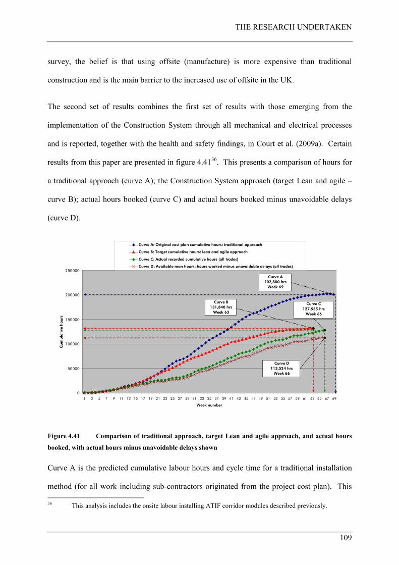
THE RESEARCH UNDERTAKEN
109
survey, the belief is that using offsite (manufacture) is more expensive than traditional
construction and is the main barrier to the increased use of offsite in the UK.
The second set of results combines the first set of results with those emerging from the
implementation of the Construction System through all mechanical and electrical processes
and is reported, together with the health and safety findings, in Court et al. (2009a). Certain
results from this paper are presented in figure 4.4136. This presents a comparison of hours for
a traditional approach (curve A); the Construction System approach (target Lean and agile –
curve B); actual hours booked (curve C) and actual hours booked minus unavoidable delays
(curve D).
0
50000
100000
150000
200000
250000
1 3 5 7 9 11 13 15 17 19 21 23 25 27 29 31 33 35 37 39 41 43 45 47 49 51 53 55 57 59 61 63 65 67 69
Week number
Cum
ula
tive h
ours
Curve A: Original cost plan cumulative hours: traditional approach
Curve B: Target cumulative hours: lean and agile approach
Curve C: Actual recorded cumulative hours (all trades)
Curve D: Available man hours: hours worked minus unavoidable delays (all trades)
Curve A
202,800 hrs
Week 69
Curve B
131,840 hrs
Week 63
Curve C
127,555 hrs
Week 66
Curve D
113,524 hrs
Week 66
Figure 4.41 Comparison of traditional approach, target Lean and agile approach, and actual hours
booked, with actual hours minus unavoidable delays shown
Curve A is the predicted cumulative labour hours and cycle time for a traditional installation
method (for all work including sub-contractors originated from the project cost plan). This
36 This analysis includes the onsite labour installing ATIF corridor modules described previously.
THE RESEARCH UNDERTAKEN
110
shows 202,800 hours with a 69 week cycle time. This curve is the benchmark against which
the Construction System method is measured (planned – curve B, and actual – curves C and
D). 202,800 hours is derived from 2,535 pair man weeks which is calculated as follows:
2,535 (pair man weeks) x 2 (men per pair) x 40 (hours per week) = 202,800 hours.
Curve B is the target predicted cumulative labour hours and cycle time after applying this
Construction System method. This shows 131,84037 hours with a 63 week cycle time. This
is the expected outcome. 131,840 hours is derived from 1,648 pair man weeks which is
calculated as follows:
1,648 (pair man weeks) x 2 (men per pair) x 40 (hours per week) = 131,840 hours.
Curve C is the actual cumulative labour hours and cycle time recorded during the sample
period. This shows 127,55538 hours with a 66 week cycle time. This is the actual outcome.
Curve D is the actual cumulative labour hours minus unavoidable breaks. This shows
113,524 hours (unavoidable breaks equate to 11% of actual time) with a 66 week cycle
time.
The onsite assembly finished at week 66 when all work was complete, this is shown as the
final point of curve C, in figure 4.41. Following an analysis of the data, the measured benefits
are presented in table 4.10.
One of the expected benefits of using the Construction System was a 35% reduction in onsite
hours and a six week cycle time reduction. The actual benefit achieved using the
37 These are paid working hours and therefore already adjusted for unavoidable delays. Workers are paid
for a 45 hour week (excluding overtime if worked) and for their lunch break.
38 These are also paid working hours and therefore already adjusted for unavoidable delays.
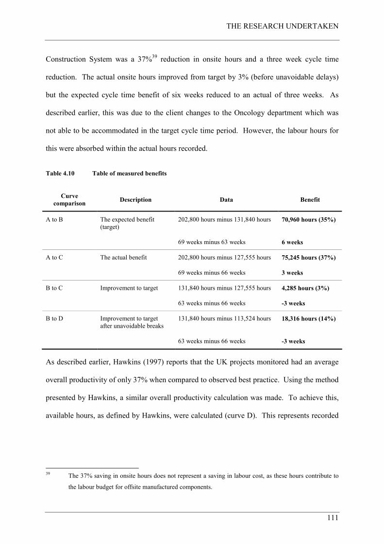
THE RESEARCH UNDERTAKEN
111
Construction System was a 37%39 reduction in onsite hours and a three week cycle time
reduction. The actual onsite hours improved from target by 3% (before unavoidable delays)
but the expected cycle time benefit of six weeks reduced to an actual of three weeks. As
described earlier, this was due to the client changes to the Oncology department which was
not able to be accommodated in the target cycle time period. However, the labour hours for
this were absorbed within the actual hours recorded.
Table 4.10 Table of measured benefits
Curve
comparison Description Data Benefit
A to B The expected benefit
(target)
202,800 hours minus 131,840 hours 70,960 hours (35%)
69 weeks minus 63 weeks 6 weeks
A to C The actual benefit 202,800 hours minus 127,555 hours 75,245 hours (37%)
69 weeks minus 66 weeks 3 weeks
B to C Improvement to target 131,840 hours minus 127,555 hours 4,285 hours (3%)
63 weeks minus 66 weeks -3 weeks
B to D Improvement to target
after unavoidable breaks
131,840 hours minus 113,524 hours 18,316 hours (14%)
63 weeks minus 66 weeks -3 weeks
As described earlier, Hawkins (1997) reports that the UK projects monitored had an average
overall productivity of only 37% when compared to observed best practice. Using the method
presented by Hawkins, a similar overall productivity calculation was made. To achieve this,
available hours, as defined by Hawkins, were calculated (curve D). This represents recorded
39 The 37% saving in onsite hours does not represent a saving in labour cost, as these hours contribute to
the labour budget for offsite manufactured components.
THE RESEARCH UNDERTAKEN
112
actual man hours minus unavoidable delays such as lunch and tea breaks40. This represents
working hours available.
Overall productivity for the sample period was then calculated using the definition of overall
productivity in Hawkins (1997):
Overall Productivity = Output
Available Time
Where:
• OUTPUT is a measured quantity of installed material to a defined requirement. The
physical output is converted to units of time by employing an earned hour’s concept
based upon best practice installation times.
• AVAILABE TIME is the total working day minus unavoidable delays such as lunch
and tea breaks.
Using this definition and hours from figure 4.42:
Overall Productivity = 131,840 hours = 116%
113,524 hours
Where:
• 131,840 hours is the total earned hours from the target Lean and agile approach (using
best practice installation times – the Construction System).
• 113,524 hours is the booked hours at completion (the sample period) minus
unavoidable delays (lunch and tea breaks), tracked using the System.
40 On average, this is one hour per day per worker: 30 minutes for lunch break; 15 minutes for morning
break; and 15 minutes for afternoon break.
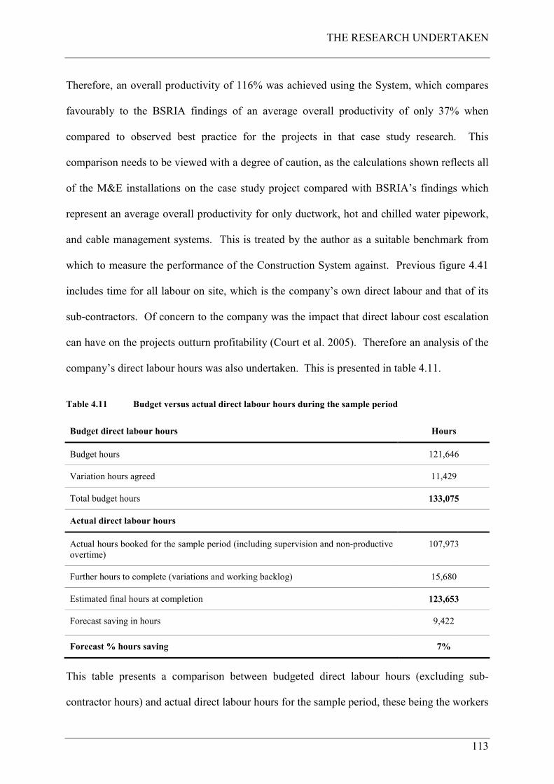
THE RESEARCH UNDERTAKEN
113
Therefore, an overall productivity of 116% was achieved using the System, which compares
favourably to the BSRIA findings of an average overall productivity of only 37% when
compared to observed best practice for the projects in that case study research. This
comparison needs to be viewed with a degree of caution, as the calculations shown reflects all
of the M&E installations on the case study project compared with BSRIA’s findings which
represent an average overall productivity for only ductwork, hot and chilled water pipework,
and cable management systems. This is treated by the author as a suitable benchmark from
which to measure the performance of the Construction System against. Previous figure 4.41
includes time for all labour on site, which is the company’s own direct labour and that of its
sub-contractors. Of concern to the company was the impact that direct labour cost escalation
can have on the projects outturn profitability (Court et al. 2005). Therefore an analysis of the
company’s direct labour hours was also undertaken. This is presented in table 4.11.
Table 4.11 Budget versus actual direct labour hours during the sample period
Budget direct labour hours Hours
Budget hours 121,646
Variation hours agreed 11,429
Total budget hours 133,075
Actual direct labour hours
Actual hours booked for the sample period (including supervision and non-productive
overtime)
107,973
Further hours to complete (variations and working backlog) 15,680
Estimated final hours at completion 123,653
Forecast saving in hours 9,422
Forecast % hours saving 7%
This table presents a comparison between budgeted direct labour hours (excluding sub-
contractor hours) and actual direct labour hours for the sample period, these being the workers
THE RESEARCH UNDERTAKEN
114
actually employed by the company. It can be seen that a saving of 7% was achieved using the
Construction System. After the sample period, a total of 15,680 hours was reserved to
complete customer variations and working backlog elements as described previously.
4.9.2.2 Health and Safety findings
In terms of safety outcomes from the sample period, the case study project had zero reportable
accidents (defined as injuries resulting in more than three days off work for the injured party).
19 minor injuries occurred during the sample period however and these were recorded in
CHt’s accident reporting system as they occurred. Each accident reported was categorised
into: accident type; date of accident; primary cause; summary details of accident; underlying
causations; behaviours; injured body parts and injury type. These have been included in
appendix G of this thesis. An overview of the place of accident, behaviours and primary
causes are as follows.
Place of accident: 8 were not at the place work itself; 11 occurred at the place of work.
Behaviours: 2 were non-compliance with procedures; 9 were human error; 7 were personal
factors (carelessness, negligence etc.); 1 was a communication failure.
Primary cause: 3 were exposure to a harmful substance; 4 were slips / trips; 1 was contact
with plant and machinery; 3 were moving / falling object, 4 were “other”; 4 were handling /
lifting or carrying.
Whilst this is not an acceptable outcome given the interventions made with the Construction
System, manual work itself is still at the core of the System and this factor will keep exposing
the worker to the risk of minor injury. Of particular note, when studying these accidents, was
the workers behaviour; all but one of the accidents could have been avoided if the worker
complied with procedures and paid more attention to avoid carelessness. This could be
overcome with more routine training given on the behavioural aspects of accident causation.
THE RESEARCH UNDERTAKEN
115
Human error could also be reduced with more attention given to further error-proofing the
installation work itself in the future.
From a health perspective, what benefits did the worker derive from good ergonomics and
workplace organisation for their wellbeing? According to Gibb (2006) the often delayed
onset of (health) conditions following exposure (to occupational health risks) should drive us
to look for solutions and do something about the problems. The interventions made in the
project, by the Construction System methods, were about providing solutions to the health
risks that would otherwise have been faced by the workers had these not been made. They
were about protecting workers from work related ailments such as MSD’s through better
management and reduction of their exposure to the causative factors (Gibb 2006).
Occupational health is about risk management and in this project the risks were managed by
applying the workplace organisation and other methods implemented in the Construction
System. This was achieved by undertaking the following:
• Providing cast-in inserts (to fix modules to the concrete slab) to avoid the need to drill
overhead into concrete for large fixings;
• Providing walk-up scaffolds or scissor lifts to avoid the need to climb ladders inside
traditional scaffold systems;
• Providing handling equipment and workbenches to avoid the need to bend over and
work or kneel on the floor, which in turn decreases the physical workload of the worker
(Sillanpaa at al. 1997);
• Providing modular assemblies with mechanical aids to lift them, which avoids the need
to cut and manually elevate components overhead, working at height. This also enables
employees to maintain an improved posture when connecting and testing the modules
(HSE 2000);
THE RESEARCH UNDERTAKEN
116
• Providing mobile trolleys for tools, components and materials etc. which avoids the
need to carry and move things around with manual handling;
• Having all materials stored in mobile trolleys at the workplace, exactly where they are
needed, thus avoiding the need to walk around looking for and carrying things to where
you need them;
• Enabling simpler assembly tasks with pre-assemblies and quick-fit components and
thereby avoiding workers being engaged in too much site cutting, drilling and assembly
work and elevation of parts into final position (Hawkins 1997).
The Construction System is an attempt to reduce the occupational health risks that
construction (M&E) workers face and to fit the work to the worker as far as reasonably
practicable. Due to the time lag between the cause and effect in occupational ill health, it was
not possible to measure the benefit of these interventions in quantifiable terms within the
scope of this research project. Also, without significant medical research and ethical
compliance, there was no way of knowing a workers health condition prior to working on the
case study project. As such, the need would have been to measure in excess of 100 M&E
worker’s physical condition, prior to and after their involvement in the Construction System
on the case study project during the sample period, and then draw conclusions from the
findings. Whilst this was not within the scope of this research project, testing the ergonomic
interventions made is an area worthy of further research. The ergonomic equipment provided
on the case study project will, it is predicted, contribute to a significant reduction in the
muscular load on the workers, as found by Sillanpaa et al. (1999). What can be said
therefore, is that the Construction System does contribute to reducing the causative problems
that lead to work related ailments, and because of this has the workers wellbeing and sending
them home safely at the end of a productive days work at its core.
THE RESEARCH UNDERTAKEN
117
Having assessed these direct measureable results from implementing the Construction
System, further observations of the System in practice we were made. These relate to
breakdowns and how they were managed (lessons learned), and the impact of the quality of
work offered to those workers engaged within the system (de-skilling or re-skilling).
4.9.3 Lessons learned
The Construction System is by no means perfectly formed and complete, it has undergone
continuous improvement since the commencement of its implementation. The main features
of the System have however worked which are the LPS production control method; ABC
parts classification; modular assembly; postponement with parts kitting and the site
operations. The use of LPS provided stabilisation which allowed work to flow, however,
disruptions and breakdowns occurred whilst operating the System during the sample period.
These disruptions were as a result of one of the Construction Physics Seven Flows (Bertelsen
et al. 2006) failing for various activities i.e. lack of information, materials, previous work,
space, crews, equipment or external conditions. Nevertheless, because of the rigour,
discussion, route cause analysis and collaboration as integral parts of the LPS weekly work
plan meetings the project team were able to manage the breakdowns and re-plan the work
accordingly. During the weekly work plan meetings, each planned activity was screened
using the seven flows and failures were analysed and collaborative corrective action taken
accordingly (within the strategic project programme). In term of continuous improvement,
these weekly work plan meetings can be considered as the projects continuous learning cycles
which can be related to Deming’s PDCA41 cycle (Deming 1986). The reasons for failures in
the System were identified and needed to be improved (the Plan to improve). The team then
41 Plan; Do; Check; Act.
THE RESEARCH UNDERTAKEN
118
did the change required to improve the problem (the Do), followed by checking to see if the
improvement had worked (the Check) and finally acting on the improvement (the Act) by
implementing the change as a routine part of the Construction System. Certain important
lessons learned from implementing the Construction System on the case study project are
contained in appendix H of this thesis. Finally, opportunities exist during future
implementation of the System, in the combining of location based scheduling with the
capability of 4D42 CAD, which would help to visually display the Week-Beat strategy and
would build upon the research conducted by Jongeling and Olofsson (2007).
4.9.4 De-skilling or re-skilling?
An attempt was made to provide a quality of work for the worker as has been previously
described in this thesis. This is discussed by Granath (1998) describing Volvo seeking to
provide its workers this quality of work as well as efficiency of production. He suggests that
a system that offers professional meaningful work is better than those that only offer unskilled
or semi-skilled work. The aspects that signify professional work are control over methods,
time and quality plus the responsibility to plan ahead and the knowledge needed to reflect on
work done. Quality of work also means good ergonomics, appropriate working tools and a
good working environment. So has the Construction System, with its modular assembly
approach, with parts kitting using push-fit / plug and play components provided this, or
because of the simpler work undertaken due to the Construction System, has this de-skilled
what they otherwise would have done on a traditional project? If this is the case then a
quality of work has not been achieved. Whilst the impact, or otherwise of this, is not the
subject of this research project, it is worthy of comment.
42 4D adds the planning dimension to 3D drawing.
THE RESEARCH UNDERTAKEN
119
The Construction System is claimed by the author to be a process innovation that incorporates
existing technological innovations to M&E products and this is what Wilson (2000) refers to
as alternative systems, components, materials and innovative methods. This technological
change that has already occurred in the UK M&E construction, as a result of these product
innovations, will have an effect on the skills of M&E workers and needs to be examined with
further research.
The Construction System utilises quick-fit pipework systems, modular wiring systems and
modular assembly (offsite manufacturing). As described in this thesis, each of the
components used was selected to be quick-fit, commercially available and tried and tested
technology. For example, small bore pipework for water and drainage is either push-fit,
crimp-fit or clamp type. This technology has been in use in the UK since the 1990’s within
the primary sectors in which CHt operates. 95% of pipe systems under 100mm diameter in
use today are from this technology, between 200mm and 400mm diameter this drops to
approximately 70% and then over 400mm this drops again to approximately 10%. The
overall average of pipework systems using this technology in the UK is 70%. Throughout its
projects 85% of pipework systems installed by CHt are below 400mm diameter and for the
higher size ranges welded systems are used which are made offsite in their manufacturing
centre. All of this is done already in CHt irrespective of the Construction System. Also in
use in the UK since the 1990’s is modular wiring systems for small power and lighting, and
nearly all large healthcare projects, under construction today, use this technology as does this
case study project. As has been described, CHt is a major provider of offsite manufactured
M&E modules and strives to use this capability today on all of its projects. Examples of other
M&E systems that do not have this degree of technological change are ductwork, large cable
and ELV cable installations.

THE RESEARCH UNDERTAKEN
120
The Construction System cannot be accused of only offering unskilled or semi-skilled work
as this is as a result of the technological change that has already occurred in the M&E industry
as a result of product innovation. All that is taken away from workers, as a result of the
Construction System, is the unsafe and wasteful effort seen on traditional projects that has
been described in this thesis. What the System is doing however, is providing safer, more
effective and productive work for the benefit of the worker and CHt together.
Added to this is Howell and Ballard’s (1999) claim that workers have more autonomy in
production decisions and enriched jobs as a consequence of the Lean principles regarding
distributed decision making, multi-skilling and pursuit of perfection. Also, Wilson (2000)
found that when using innovative M&E installation techniques and products, in addition to
the improvements in productivity, many other benefits for the whole construction team were
produced. These benefits include:
• Improved working practices and buildability;
• A more efficient well trained and motivated workforce via staff training in innovative
working methods;
• Recognition as an innovative company.
The author believes that the System is in fact re-skilling M&E workers in modern methods of
construction and will lead to a new breed of well trained, multi-skilled construction assembly
workers with good working conditions who are relatively highly paid. Finally, both Green
(1999) and Jorgensen and Emmitt (2008) miss the safety argument in their criticism of Lean
Construction previously described in thesis. Surely by providing safer more effective and
productive work that benefits the worker and CHt together, is better than not doing Lean
Construction at all and ignoring the problems faced today that places workers at risk of injury
and creates poor productivity? The author believes it is.

THE RESEARCH UNDERTAKEN
121
4.9.5 Summary of step 8
This section has described the results emerging from the implementation of the Construction
System on the case study project the Maternity and Oncology building. The results emerging
are showing that because of the implementation of the Construction System, the case study
project has had the following benefits:
• A 37% reduction in the number of operatives required onsite thereby exposing less
workers to lower risks of injury leading to zero reportable accidents;
• Improved workers wellbeing by providing good ergonomics, a good working
environment and simpler assembly tasks for those required on site;
• Reduced process waste thereby improving productivity leading to a 7% saving against
the direct labour budget allocation;
• Achieved 116% overall productivity when compared to that found by BSRIA;
• Successfully developed an innovative frameless ATIF M&E module where a 93%
reduction in on site labour was achieved together with a 8.62% cost benefit;
• Completed onsite assembly on time thereby not compressing commissioning periods
leading to handing over the built facilities on time and to budget to the customer’s
satisfaction.
4.10 CHAPTER SUMMARY
This chapter has described the actual research undertaken through each of the research steps
using the chosen methods on the case study project. The aim of the research was to improve
site operations for CHt, making them safer for the worker and at the same time improving
productivity, thereby avoiding labour cost escalation and the subsequent margin slippage that
can occur as a result. This was achieved by achieving the six stated objectives through the
THE RESEARCH UNDERTAKEN
122
eight steps of the research process (the ninth step being the production of this thesis). The
research identified the issues that cause poor productivity and health and safety performance
in M&E construction and developed a conceptual system using Lean methods from other
industries to overcome these issues. It then developed the conceptual Construction System
into real and meaningful methods that were applied and tested on the case study project
during the sample period. The results emerging from the implementation of the System have
been described and lessons learned have been recognised and implemented back into the
System. The next chapter concludes the research undertaken.

FINDINGS AND IMPLICATIONS
123
CHAPTER 5 FINDINGS AND IMPLICATIONS
5.1 INTRODUCTION
This chapter concludes the research and discusses its contribution to existing theory and
practice, its impact on the industrial sponsor and on the wider industry. Finally, the chapter
provides recommendations for further research and a critical evaluation of the research
undertaken.
5.2 CONCLUSIONS
5.2.1 Achievement of the stated aim and objectives
The overarching aim of this research project was to develop and implement a new way of
working for CHt in order to improve the performance of its projects site operations, making
them safer for the worker and to improve productivity as a countermeasure to the problems
that CHt faces in the M&E industry within the UK construction sector.
In order to achieve this aim, six specific objectives were defined:
Objective 1: To reveal and understand the issues that lead to poor health, safety and
productivity performance;
Objective 2: To reveal and understand Lean methods in use in other industries;
Objective 3: To develop a conceptual Construction System that adopts Lean methods from
other industries that can be applied to M&E construction;
Objective 4: To turn the theory of the developed System into practice with real and practical
methods that is able to be applied to a case study project in the real world;
FINDINGS AND IMPLICATIONS
124
Objective 5: To set realistic and achievable targets against which the System can be
measured during implementation;
Objective 6: To implement the System on a live case study project and to measure the
results emerging during the implementation.
These objectives have been met and satisfied through the achievement of each of the research
process steps described in the previous chapter. This research process has concluded with
certain findings emerging from the implementation of the Construction System which leads to
meeting the overarching aim of the research project.
The key findings of the research project are described in the last chapter of this thesis in terms
of the results emerging from the implementation of the Construction System and because of
this implementation the case study project has had many benefits. The project needed 37%
fewer workers onsite than would otherwise have been required if a traditional method had
been used. This has meant that the reduced numbers of operatives were exposed to lower
risks of injury because those required onsite were provided with good ergonomics, a good
working environment and simpler assembly tasks. As a result of this, zero reportable
accidents occurred on the project; however, it is acknowledged that minor injuries still
happened. These can be reduced in the future with more training given to workers on the
behavioural aspects of accident causation and with attention given to error-proofing the
assembly work itself. In addition, manual work was at the core of the onsite assembly process
which was a factor in the causative problems experienced. This also needs attention in the
future to help reduce or even eliminate these factors.
From a workers health perspective, the interventions made in the project, by using the
Construction System methods, were about providing solutions to the health risks that would
otherwise have been faced by the workers had these not been made. These were about
FINDINGS AND IMPLICATIONS
125
protecting workers from work related ailments such as MSD’s through better management
and reduction of their exposure to the causative factors. The Construction System methods
have contributed to reducing the causative problems and because of this has the workers
wellbeing, and sending them home safely at the end of a productive days work, at its core.
In terms of productivity, the Construction System has reduced process waste traditionally
seen in construction as revealed in this research project. Through utilising the System thus
reducing this waste, the case study project has achieved 116% overall productivity which
compares favourably with that found by BSRIA in their research project who reported only
37% for the four UK projects monitored (Hawkins 1997). Also, a 7% direct labour cost
saving was made meaning that the project gained control of this large project cost variable
that, if not controlled in such a way, can lead to margin slippage on projects (Court et al.
2005). Of great importance also is the customer, and for the case study project the customer
had the built facilities delivered on-time, on budget and commissioned properly to their
satisfaction.
The findings show that the Construction System is a successful set of countermeasures that
acts as an antidote to the problems that CHt faces in the UK M&E construction industry. The
transformation that has occurred is the creation of a step-change in undertaking M&E
construction work, which has realised a significant improvement in performance for CHt that
has “Transformed Traditional Mechanical and Electrical Construction into a Modern Process
of Assembly”.
5.2.2 Is it a Lean System?
The System is built on Lean principles, the goal of which is to eliminate any human activity
which absorbs resources but creates no value (Womack and Jones 1996). Lean concepts
FINDINGS AND IMPLICATIONS
126
include creating value from the customer’s perspective; to identify all the steps across the
whole value stream; to make actions that create value flow; to only make what is pulled by the
customer Just-In-Time; and to strive for perfection by continually removing successive layers
of waste.
Customers exist in the System at many levels. There are the final customers, the users of the
hospital and the owner who will operate it who had the facility handed over on time and on
budget. The commissioning team (the customer of onsite assembly) had the M&E systems
completed on time to be able to set them to work properly and with the right time to do this.
Each of the trade teams in the onsite assembly phase (each the customer of the previous step
in the assembly process) had space, materials, information, equipment and previous work
when they needed it in order to carry out their own work uninterrupted in a safe and effective
manner.
Customer value (from their perspective) has been created in the System, as far as has been
possible, by reducing the non-added value wasteful activities that were revealed during the
research steps. The steps in the value stream were identified in the projects value chain with
each of the incremental actions within each step delivering value to each respective customer.
Flow was created by allowing work to be undertaken free from disruption by others, with
teams flowing from one construction zone to another using the Week-Beat method without
delay. This pulled materials, information and equipment Just-In-Time to match this flow.
Perfection has been pursued by recognising breakdowns in the System during weekly work
plan meetings with action being taken to take account of and remedy these breakdowns.
FINDINGS AND IMPLICATIONS
127
5.3 CONTRIBUTION TO EXISTING THEORY AND PRACTICE
According to Arbulu and Zabelle (2006), organisations all over the world have been looking
for ways to increase competitive advantage for the delivery of capital projects through the
application of Lean concepts and techniques. Arbulu and Zabelle report that some
organisations have achieved pockets of excellence and others have simply failed but truly
competitive advantage has not yet been achieved. This research project has followed the
methodology recommended by Arbulu and Zabelle by adopting a narrow and deep approach
and, by ensuring with CHt’s top management support, that all of the conditions for success
were enabled. It has taken a holistic view to bring together manufacturing methods and
techniques to design a Construction System to overcome the issues, or problems, that CHt
faces in the UK M&E construction industry.
The research has achieved two levels of innovation, one at a process level and one at a
product level. The process innovation is the development and successful implementation of
the Construction System, which is a combination of methods acting together as an antidote to
the research problem. The product innovation is the development of the innovative method
for assembling, transporting and installing frameless M&E modules (the ATIF), whereby
modularisation can be achieved with or without an offsite manufacturing capability.
As such, a whole system has been designed implementing a major number of Lean and agile
manufacturing methods for which no evidence has been found by the author that this has been
done before in such a comprehensive way in construction, other than in pockets of excellence
(Arbulu and Zabelle 2006). The findings from the case study, in the words of the Industrial
Sponsor, are far exceeding the company’s expectations of performance improvement and will
provide the company with an increase in competitive advantage as a result.
FINDINGS AND IMPLICATIONS
128
The contribution to existing theory and practice is the combination of countermeasures
described in this thesis that have been developed and incorporated into a wider Construction
System, in the same way that manufacturing has used this strategy with great success.
This work is feeding into other ongoing research initiatives in Lean Construction which
include research work at Loughborough University’s Lean Construction Data Laboratory and
the Lean Commercial Management in Construction Programme, both of which are IMCRC43
funded projects. Also, Loughborough’s Lean Construction taught module (module CVP053)
includes work from this research which is being taught as industry best practice to new
students.
5.3.1 Interest generated by the System
Since the emergence of these results, the author has been invited to present the findings of this
research project at significant forums in the construction industry both in the UK and the
USA, these include:
• Lean Construction Institute (USA) 10th annual Lean Construction Congress, Boulder
City, Colorado, USA, held in October 2008;
• Lean Construction Institute (UK) Annual Summit, Birmingham, UK, held in November
2008;
• The Chartered Institute of Building Services Engineers National Conference, London,
UK, held in April 2009.
43 Innovative Manufacturing and Construction Research Centre.
FINDINGS AND IMPLICATIONS
129
The presentations and subsequent discussions have been received extremely well and requests
have been made for further information regarding the research which has been provided in
order to contribute to, and pass on new knowledge.
Following the presentation to the 10th Annual Meeting of the Lean Construction Institute,
feedback was that the report provoked a significant rethinking that is changing the design and
installation of M&E modules in the United States and the application of this approach is
under active consideration by 2 major mechanical contractors and three hospital construction
programs in the USA. The ATIF’s have also been used by CHt on a separate project at
Birmingham International Airport therefore proving their suitability and adaptability across
different project types.
The knowledge from this research project has been disseminated internationally to academia
and industry through conferences, workshops, and journal papers. The methods developed in
the research project have been accepted through the peer review process of three IGLC
conferences and two journals including the American Society of Civil Engineers Journal, the
Practice Periodical on Structural Design and Construction.
5.4 IMPLICATIONS / IMPACT ON THE SPONSOR COMPANY
The implications to the sponsor company were discussed following presentation of the case
study findings to the Industrial Supervisor, CHt’s Business Leader. According to the
supervisor, the outcome of the research project has exceeded the expectations of the company
and can be summarised at two levels which are company and customer level implications.
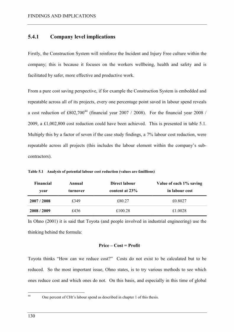
FINDINGS AND IMPLICATIONS
130
5.4.1 Company level implications
Firstly, the Construction System will reinforce the Incident and Injury Free culture within the
company; this is because it focuses on the workers wellbeing, health and safety and is
facilitated by safer, more effective and productive work.
From a pure cost saving perspective, if for example the Construction System is embedded and
repeatable across all of its projects, every one percentage point saved in labour spend reveals
a cost reduction of £802,70044 (financial year 2007 / 2008). For the financial year 2008 /
2009, a £1,002,800 cost reduction could have been achieved. This is presented in table 5.1.
Multiply this by a factor of seven if the case study findings, a 7% labour cost reduction, were
repeatable across all projects (this includes the labour element within the company’s sub-
contractors).
Table 5.1 Analysis of potential labour cost reduction (values are £millions)
Financial
year
Annual
turnover
Direct labour
content at 23%
Value of each 1% saving
in labour cost
2007 / 2008 £349 £80.27 £0.8027
2008 / 2009 £436 £100.28 £1.0028
In Ohno (2001) it is said that Toyota (and people involved in industrial engineering) use the
thinking behind the formula:
Price – Cost = Profit
Toyota thinks “How can we reduce cost?” Costs do not exist to be calculated but to be
reduced. So the most important issue, Ohno states, is to try various methods to see which
ones reduce cost and which ones do not. On this basis, and especially in this time of global
44 One percent of CHt’s labour spend as described in chapter 1 of this thesis.
FINDINGS AND IMPLICATIONS
131
recession, CHt can maintain competitiveness with reduced prices by reducing costs in a
structured, confident manner (as opposed to pure cost cutting) using the competitive
advantage that the Construction System offers.
Furthermore, it is the view of the Industrial Supervisor that given the findings that this
research project has revealed, and should this be embedded and repeated across all of CHt’s
projects, that this would reduce the organisations operational risk profile thereby enhancing its
enterprise value (explained earlier in this thesis). This is because the investment market
considers construction risky so by applying the Construction System across all its projects, the
company will have more predictable operational performance leading to more predictable
revenue streams. This in turn means higher predictability of earnings therefore higher
investor confidence. This is supported by DETR (1998) who report that the under-
achievement of construction is graphically demonstrated by the City’s view of the
construction industry as a poor investment. It reports that the City regards construction as an
industry that is unpredictable, competitive on price not quality and with too few barriers to
entry for poor performers. With few exceptions investors cannot indentify brands among
companies to which they can attach future value and as a result there are few loyal, strategic
long-term shareholders in quoted construction companies. The report states that discussions
with City analysts suggest that effective barriers to entry in the construction industry, together
with structural changes that differentiated brands and improved companies’ “quality of
earnings” (i.e. stability of margins), could result in higher share prices and more strategic
shareholders. It is believed, the report states, that such a change towards stability of profit
margins would be at least as highly valued by the City as a simple increase in margins.
Other project cost benefits are reduced risk contingencies and preliminaries. Risk
contingencies are built into project costs to cover the probability of cost overruns in
FINDINGS AND IMPLICATIONS
132
accordance with risk assessments carried out at tender stage and part of this is for labour cost
escalation. If projects can be delivered without overspending on labour then the associated
risk contingency can be saved, or even eliminated, when confidence in the System is
established over time. Costs for preliminaries can also be reduced should the System result in
shorter construction cycle times. Again these costs can be saved at a project level or reduced
over time as confidence is established in the System.
5.4.2 Customer level implications
According to Hawkins (1997), maximising the output on site is essential in order to increase a
contractor’s performance and the value for money investment of the customer. On this point,
the Industrial Supervisor sees the Construction System delivering improved customer
satisfaction, if for no other reason than providing certainty of time, cost and quality of its
delivered projects. If construction cycle time is reduced and the built facilities are available
earlier for end-user occupation, and dependant upon the facility, then revenue streams may be
available earlier for the customer. Another customer level implication relates to relational
forms of contract such as target cost projects, or pain/gain share contract forms (or similar).
The potential savings generated within the project can then be shared between the customer
and the contractor, to both their mutual benefit.
5.4.3 Sponsor company implications / impact summary
The Construction System has been shown to be successful following its implementation on
the case study project. The System, the author confirms, is repeatable across CHt’s project
portfolio but with adaption to suit the particular project characteristics. It will mean
investment in training and development of people and equipment, to allow the adoption of
this new method or working, otherwise constraints and barriers will continue to exist.
FINDINGS AND IMPLICATIONS
133
The narrow and deep approach to implementation needs to be adopted, one project at a time,
until all projects operate to the new business model. Teams to manage these future projects
will need to be facilitated, individuals will need to be trained and mangers will need to be
coached. These teams are composed of individuals, and these individuals are the ones who
could potentially resist the change. Change can occur quite rapidly but adjusting to the
change can often take time and effort (Arbulu and Zabelle 2006). In addition, further
investment will be required to procure and develop equipment needed for the mobile work
cells and parts centres for example, and then to manage and maintain these. This is an
investment cost for the further development and upkeep of the System that CHt does not have
at this time.
These potential constraints and barriers are therefore people, culture and change; lack of
investment for training and development of people and the lack of investment for the
development and maintenance of the System for wider adoption within CHt. Such constraints
and barriers need to be acknowledged by CHt to be able to successfully diffuse the System
across the wider business. Knowledge transfer mechanisms are also required to aid the
diffusion and this will require CHt to produce new standard operating procedures within its
quality management system. To take advantage of the benefits for wider adoption within the
business, CHt will have to develop metrics to measure the diffusion of the System within the
company. In the opinion of the author, metrics are required to measure if the five elements
for successful implementation are in place for each new project in the roll-out of the narrow
and deep approach (Arbulu and Zabelle 2006). These elements are:
1 The vision;
2 The skills needed;
3 The incentive needed;
FINDINGS AND IMPLICATIONS
134
4 The resources needed;
5 The action plan needed.
Without these metrics, and therefore the elements required for successful implementation, the
implementation effort will most likely fail both within CHt and in the wider industry. CHt
also need to develop a productivity measurement system as they do not have this at the time
of completing this research project. They can however use the methods developed in the
Construction System as a basis for one, combined with the findings achieved to act as
benchmarks for measurement of success.
As well as this, new methods of estimating future bids will be required in order to build-in the
competitive advantage that the Construction System offers to win new work and this needs to
be developed in the near future by CHt.
Finally, in the same way that Toyota has developed a source of competitive advantage with
the Toyota Production System, CHt are in a position to enhance their reputation within the
industry, similarly leading to the System being a source of competitive advantage for them.
5.5 IMPLICATIONS / IMPACT ON WIDER INDUSTRY
As has been shown, the Construction System is a set of countermeasures to overcome the
problems that M&E companies face today in construction. Whilst the System is developed
for CHt, it can, with local adaption, be transferrable and successful within the wider industry.
If nothing else, from a health and safety perspective, the industry should use some, if not all
of the countermeasures described in this thesis. If just providing clear space, a good working
environment, good ergonomics and everything the worker needs, contributes to their
wellbeing and health and safety, then we have done our job to help reduce workers exposure
to injury from either health or safety factors as a result of working in the construction
FINDINGS AND IMPLICATIONS
135
industry. Just by providing workers a workbench (BSRIA best practice no. 62), which results
in them not having to kneel or work on the floor, will help reduce the problems that cause
injury. Plus of course improving productivity in an industry where this has traditionally been
poor thus leading to changing the poor performance of construction, as reported in this thesis.
Finally though, in the same way that barriers and constraints exist to the wider adoption of the
System within CHt, these will also exist within the wider industry and the industry therefore
needs to take due cognisance of these barriers, as does CHt.
5.6 RECOMMENDATIONS FOR INDUSTRY / FURTHER
RESEARCH
Further research is recommended by the author in order to build upon and improve the
Construction System to the benefit of CHt and the wider industry. These recommendations
are drawn from the findings and implications of this research project, and are meant to further
develop the System with more research that has fallen outside the scope of this project or
became evident from the process undertaken. Further research recommended by the author is
as follows:
• Knowledge transfer mechanisms between projects (repeatability of the System on
varying project types);
• Development of a productivity measurement system;
• Development of metrics to measure the diffusion of the research findings within the
company and the wider industry;
• Estimating for higher productivity and reduced project cycle-times to build-in the
competitive advantage into new bids;
FINDINGS AND IMPLICATIONS
136
• Implications on the worker in terms of motivation, de-skilling or re-skilling (the dark
side of Lean; or otherwise);
• Health impacts of the Construction System on the worker;
• Error proofing work to reduce human error in M&E manual work;
• Combining of location based scheduling with the capability of 4D CAD which would
help to visually display the Week-Beat strategy.
5.7 CRITICAL EVALUATION OF THE RESEARCH
The most important critical evaluation of this research project concerns its implementation.
Had the thesis author not been the Project Leader then would the Construction System have
been so successful? In other words, had the author been a pure researcher imposed onto the
project by CHt, would a traditionally thinking team accept the imposition of new thinking?
This point strongly reinforces Arbulu and Zabelle (2006) conditions for success as described
in chapter 3. Notwithstanding this, the implementation of the Construction System was
successful and proves what can be done when deliberate interventions are made to overcome
the problems that the construction industry faces. The recommendation for those
implementing change, is to ensure that these conditions are in place for any change
programme to be implemented successfully.
This research project designed and implemented the Construction System on the case study
project which is a new-build hospital facility. The System can be adapted for other facilities
which will have different construction characteristics and different M&E systems. The author
believes that this is possible using the underpinning methodologies outlined in this thesis.
Sequences between installation teams, types of modules, workplace equipment etc. merely
FINDINGS AND IMPLICATIONS
137
need to be modified to suit to the actual characteristics of the particular project being
undertaken.
5.8 CHAPTER SUMMARY
The M&E construction industry (and construction generally) has been shown to have
historically poor health, safety and productivity performance and these problems face the
sponsor company, CHt and others within the industry. The research presented in this thesis
has developed a Lean and agile Construction System to overcome these problems and has
implemented this on a complex M&E case study project in the healthcare sector of UK
construction. With the support from Crown House Technologies and Loughborough
University, the research has achieved the proposed aim and objectives. The System has been
shown to be successful in its implementation, has made a positive impact on the sponsor
company and has the potential to be implemented in the wider industry.
Finally, readers of this thesis and those wishing to embark on doing things differently and to
move away from current practice and knowledge, are reminded of the following phrase…
“If you always do what you always did, then you’ll always get what you always got…”

FINDINGS AND IMPLICATIONS
138
REFERENCES
139
CHAPTER 6 REFERENCES
Abdelhamid, T. S., and Everett, J. G. (1999). Physiological demands of concrete slab placing
and finishing work. Journal of Construction Engineering and Management, ASCE,
125(1), 47-52.
Akinci, B., Fischer, M., Kunz, J., and Levitt, R., (2002). Representing work spaces
generically in construction method models. J. Constr. Eng. Manage., 128(4), 296-305.
Akinci, B., Fischer, M., Kunz, J., (2002a). Automated generation of work spaces required by
construction activities. J. Constr. Eng. Manage., 128(4), 306-315.
Arbulu, R., and Zabelle, T., (2006). Implementing Lean in construction: how to succeed.
Proceedings of the 14th annual conference of the International Group for Lean
Construction, Santiago, Chile, 2006.
Ballard, G., (2000). The Last Planner System of production control. PhD thesis, Department
of Civil Engineering, University of Birmingham, Birmingham, UK.
Ballard, G. and Matthews, O., (2004). Championship – prefabrication and assembly.
Proceedings of the 12th annual conference of the International Group for Lean
Construction, Elsinore, Denmark, August 3-5, 2004.
Bertelsen, S., Koskela, L., Henrich, G., and Rooke, J. (2006). Critical flow-towards a
construction flow theory. Proc., Fourteenth Annual Conf. of the Int. Group for Lean
Construction (IGLC-14), Santiago, Chile, 31-40.
Burbidge, J.L., (1996). Period flow control. Clarendon Press, USA.
REFERENCES
140
Bridger, R. S., (2003). Introduction to ergonomics. Taylor and Francis, New York, USA.
Cassell, C., and Symon, G., (2004). Essential guide to qualitative methods in organisational
research. SAGE publications, UK.
Checkland, P., and Scholes, J., (1992). Soft systems methodology in action. Wiley
Publications, UK.
Churcher, D., (2009). A design framework for building services 2nd edition, BSRIA technical
note BG 6/2009, The Building Services Research and Information Association,
Bracknell, UK.
Coghlan, D. and Brannick, T., (2003). Doing action research in your own organisation.
SAGE publications, UK.
Colledge, B., (2005). Relational contracting – creating value beyond the project. Lean
Construction Journal, Vol. 2 #1 April 2005.
Court, P., Pasquire, C., Gibb, A.G.F., and Bower, D., (2005). Lean as an antidote to labour
cost escalation on complex mechanical and electrical projects. Proceedings of the 13th
annual conference of the International Group for Lean Construction, Sydney,
Australia, 2005.
Court, P., Pasquire, C., Gibb, A.G.F., and Bower, D., (2006). Design of a Lean and agile
Construction System for a large and complex mechanical and electrical project.
Proceedings of the 14th annual conference of the International Group for Lean
Construction, Santiago, Chile, 2006.
REFERENCES
141
Court, P., Pasquire, C., Gibb, A.G.F., and Bower, D., (2007). Transforming traditional
construction into a modern process of assembly using Construction Physics.
Proceedings of the 15th annual conference of the International Group for Lean
Construction, East Lansing, USA, 2007.
Court, P., Pasquire, C., Gibb, A.G.F., and Bower, D. (2008). Modular assembly in healthcare
construction – A mechanical and electrical case study. Proceedings of the 16th annual
conference of the International Group for Lean Construction, Manchester, United
Kingdom, 521-531.
Court, P., Pasquire, C., Gibb, A.G.F., (2009). Modular assembly with postponement to
improve health, safety and productivity in construction. J. Practice Periodical on
Structural Design and Construction. 14(2), 81-89.
Court, P., Pasquire, C., Gibb, A.G.F., (2009a). A Lean and agile Construction System as a set
of countermeasures to improve health, safety and productivity in mechanical and
electrical construction. Lean Construction Journal, November 2009.
DETR (1998), Rethinking construction, Department of the Environment, Transportation and
the Regions, London, UK.
Deming, W. E., (1986). Out of the crisis. MIT Centre for Advanced Engineering Study.
Dicks, M., (2002). Commissioning management - how to achieve a fully-functioning
building. BSRIA application guide 5/2002. ISBN 0 86022 599-2.
Everett, J. G. (1999). Overexertion injuries in construction. Journal of Construction
Engineering and Management, ASCE, 125(2), 109-114.
REFERENCES
142
Fellows, R. F., and Liu, A. M. M., (2003), Research methods for construction. Blackwell
Publishing, Oxford, UK.
Forza, C. (1996). Work organisation in Lean production and traditional plants – what are the
differences? Int. J. of Ops. Manage., Vol. 16. No. 2, 1996, 42-62.
Fredriksson, P., (2006). Mechanisms and rationales for the coordination of a modular
assembly system – The case of Volvo cars. International Journal of Operations and
production Management, Vol 26 No. 4 pp 350-370.
Gibb, A.G.F., (2006) (Keynote). Occupational health: slow accidents need solutions fast, in
Fang, Choudry & Hinze (eds), Global Unity for Safety & Health in Construction, Proc.
of CIBW99 Int. Conf., June 2006, Beijing, Tsinghua University Press, pp. 22-33.
Granath, J.A., (1998). Torlanda to Uddevalla via Kalmar: a journey in production practice in
Volvo. Seminário Internacional Reestruturaçã Productiva, Flexibilidade do Trabalho e
Novas Competências Profissionais COPPE/UFRJ, Rio de Janeiro, Brasil.
Green, A., (1999). The dark side of Lean Construction: exploitation and ideology. Proc.,
Seventh Annual Conf. of the Int. Group for Lean Construction (IGLC-7), Berkeley,
California, 1999.
Goldratt, E. M., and Cox, J., (2004), “The goal: a process of ongoing improvement.” Gower
Publishing, Aldershot, UK.
Goodier, C.I., Gibb, A.G.F., (2005). Barriers and opportunities for offsite in the UK.
Systematic innovation in the management of projects and processes. Abdul Samad
Kazi (ed), cib Helsinki international joint symposium, pp. 148-158, ISBN 952 5004 64
3.
REFERENCES
143
Guo, S. J., (2002). Identification and resolution of work space conflicts in building
construction. J. Constr. Eng. Manage., 128(4), 287-295.
Hanna, A. S., Peterson, P., and Lee, M-J., (2002). Benchmarking productivity indicators for
electrical/mechanical projects. J. Constr. Eng. Manage., 128(4), 331-337.
Hawkins, G., (1997). Improving M&E site productivity, BSRIA technical note TN 14/97, The
Building Services Research and Information Association, Bracknell, UK.
Hawkins, G., (2002). Site productivity – 2002. A guide to the uptake of improvements,
BSRIA technical note TN 13/2002, The Building Services Research and Information
Association, Bracknell, UK.
Health and Safety Executive, (2000). Backs for the future: safe manual handling in
construction, HSE books, Norwich, UK.
Health and Safety Executive, (2003). Understanding ergonomics at work: reduce accidents
and ill health and increase productivity by fitting the task to the worker, HSE Books,
2003.
Health and Safety Executive, (2007). Health and safety in the construction industry.
<http://www.hse.gov.uk/construction/index.htm> (Mar. 4, 2007)
Health and Safety Executive, (2007a). Better backs in construction.
<http://www.hse.gov.uk/construction/backs/index.htm> (Mar. 4, 2007).
Health and Safety Executive, (2007b). Musculoskeletal disorders – HSE and MSD’s.
<http://www.hse.gov.uk/msd/hsemsd.htm> (Mar. 4, 2007).
REFERENCES
144
Henrich, G., Tilley, P., Koskela, L., (2005). Context of production control in construction.
Proceedings of the 13th annual conference of the International Group for Lean
Construction, Sydney, Australia.
Hopp, W. J., and Spearman, M. L. (2001). The MRP crusade. Factory physics, 2nd Ed.,
Irwin/McGraw-Hill, New York, USA, 109-150.
Horman, M. J., Orosz, M. P., and Riley, D. R. (2006). Sequence planning for electrical
construction. J. Constr. Eng. Manage., 132(4), 363-372.
Howell, G., (1999). What is Lean Construction, Proc. Seventh Annual Conf. of the Int.
Group for Lean Construction (IGLC-7), Berkeley, California, 1999.
Howell, G., Laufer, A., and Ballard, G. (1993). Interaction between subcycles – one key to
improved methods. J. Constr. Eng. Manage., 119(4), 714-728.
Howell, G., and Ballard, G. (1999). Bringing light to the dark side of Lean construction: a
response to Stuart Green. Proc., Seventh Annual Conf. of the Int. Group for Lean
Construction (IGLC-7), Berkeley, California, 1999.
Howell, G., and Ballard, G. (1999a). The design of construction operations. LCI white paper-
4. Lean Construction Institute Implementation Workshop, Portland, Oregon, 1999.
Jongeling, R., and Olofsson, T., (2007). A method of planning for work-flow by combined
use of location based scheduling and 4D CAD. Automation in Construction, volume
16, issue 2, March 2007, pp. 189-198.
REFERENCES
145
Jorgensen, B., and Emmitt, S., (2008). Lost in transition: the transfer of Lean manufacturing
to construction. Engineering, Construction and Architectural Management, Vol. 15
No. 4, 2008, pp. 383-398.
Kivi, P., and Mattila, M. (1991). Analysis and improvement of work postures in the building
industry: application of the OWAS method. Applied Ergonomics, 22(1): 43-48.
Koningsveld, E. A. P. and Van Der Molen, H. F. (1997), History and future of ergonomics in
building and construction. Ergonomics, 1997, vol. 40, no.10, 1025-1034.
Koskela, L., (2004). Moving on – beyond Lean Thinking. Lean Construction Journal, Vol. 1
#1 October 2004.
Koskela, L., (2004a). Making-do – the eighth category of waste. Proceedings of the 12th
annual conference of the International Group for Lean Construction, Elsinore,
Denmark, August 3-5, 2004.
Larsen, J., Odgaard, G., and Buch, S., (2003). A trade union’s view of the building process.
Proceedings of the 11th annual conference of the International Group for Lean
Construction, Blacksburg, Virginia, July 22-24, 2003.
Latham, M., (2004). Constructing the team, joint review of procurement and contractual
arrangements in the UK construction industry. HMSO, London, 1994.
Lean Construction Institute (2009): What is Lean Construction? <
http://www.Leanconstruction.org/>, (Jan. 5, 2009).
Lean Enterprise Institute (2003). Lean lexicon – a graphical glossary for Lean thinkers. The
Lean Enterprise Institute, Massachusetts, USA.

REFERENCES
146
Liker, J. K. (2004). The Toyota way: 14 management principles from the world’s greatest
manufacturer, McGraw-Hill, New York, USA.
Luckins, (2003). Mechanical installation times guide for estimators. Trade Services
Information Limited, 2003, England.
Luckins, (2003). Electrical installation times guide for estimators. Trade Services Information
Limited, 2003, England. ISBN 0 5912985 3 4.
Maslow, A. H., (1943). Theory of human motivation, Psychological Review, 50, 370-396.
Mason-Jones, R., Naylor, B., and Towell, D., (2000). Engineering the leagile supply chain.
International Journal of Agile Management Systems, 2/1, 54-61.
Mawdesley, M.J., and Long, G., (2002). Prefabrication for Lean building services
distribution. Proc. Tenth Annual Conf. of the Int. Group for Lean Construction
(IGLC-10), Gramado, Brazil.
McNamara, Brian E., (1986). Ergonomics: Maximising the human resource. Logistex
Forum, May 6-8, 1986.
Naylor, J. B., Naim, M. M., and Berry, D., (1999). Leagility: integrating the Lean and agile
manufacturing paradigms in the total supply chain. International Journal of Production
Economics (1999), No. 62, pp. 107-18.
Ohno, T., (1988). Toyota Production System, beyond large scale production. Productivity
Press, USA.
REFERENCES
147
Parsloe, C. J., (1997). Allocation of design responsibilities for building services engineering,
BSRIA technical note TN 21/97, The Building Services Research and Information
Association, Bracknell, UK.
Pasquire, C.L., and Connolly, G.E., (2002). Leaner construction through off-site
manufacturing. Proc. Tenth Annual Conf. of the Int. Group for Lean Construction
(IGLC-10), Gramado, Brazil.
Pasquire, C.L., and Connolly, G.E., (2003). Design for manufacture and assembly. Proc.
Eleventh Annual Conf. of the International Group for Lean Construction (IGLC-11),
Blacksburg, Virginia.
Pasquire, C., Gibb, A.G.F., and Blissmass, N., (2005). What should you really measure if you
want to compare prefabrication with traditional construction? Proceedings of the 13th
annual conference of the International Group for Lean Construction, Sydney,
Australia, 2005.
Porter, M. E., (1985). Competitive advantage. Simon and Schuster, New York, USA.
Rother, M., and Harris, R., (2001). Creating continuous flow – an action guide for managers,
engineers and production associates. The Lean Enterprise Institute, Massachusetts,
USA.
Sillanpaa, J., Lappalainen, J., Kaukiainen, A., Viljanen, M., Laippala, P., (1999). Decreasing
the physical workload of construction work with the use of four auxiliary handling
devices. International Journal of Industrial Ergonomics, no.24, 1999, 211-222.
REFERENCES
148
Skipworth, H., and Harrison, A., (2004). Implications of form postponement to
manufacturing: a case study. Int. J. Prod. res., 15 May 2004, vol. 42, no. 10, 2063-
2081.
Smith, E, E., Nolen- Hoeksema, S., Fredrickson, B. L., and Loftus, G. R., (2003). Atkinson
and Hilgard's introduction to psychology. Wadsworth/Thomson Learning, Belmont,
USA.
Sporrong, H., Sandsjo, L., Kadefors, R., Herberts, P., (1999). Assessment of workload and
arm position during different work Sequences: a study with portable devices on
construction workers. Applied Ergonomics, no.30, 1999, 495-503.
The Chartered Institute of Building Services Engineers. (2003). Commissioning management
– CIBSE commissioning code M: 2003. The Chartered Institute of Building Services
Engineers, London, UK.
The Productivity Press Development Team (2002). Standard work for the shopfloor.
Productivity Press, USA.
Thomas, H. R., Horman, M. J., and de Souza, U. E. L., (2004). “Symbiotic crew relationships
and labor flow.” J. Constr. Eng. Manage., 130(6), 908-917.
Ulrich, K. T., Eppinger, S. D. (2004). Product design and development, 3rd Ed., McGraw Hill,
New York, USA, 163-186.
Wilson, D., (2000). Innovative M&E installation, BSRIA ACT 9/2000, The Building Services
Research and Information Association, Bracknell, UK.
REFERENCES
149
Winch, G. M., and North, S., (2006). Critical space analysis. J. Constr. Eng. Manage.,
132(5), 473-481.
Womack, J.P. and Jones, D.T., (1996). Lean Thinking, banish waste and create wealth in your
organisation. Simon and Schuster, UK.
Yang, B., and Burns, N. (2003). Implications of postponement for the supply chain. Int. J.
Prod. res., 2003, vol. 41, no. 9, 2075-2090.
Yin, R. K., (2003), Case Study Research: Design and Methods. SAGE Publications, USA.

REFERENCES
150
APPENDICES
151
APPENDICES
Appendix A: Paper 1 (refereed, conference)
Appendix B: Paper 2 (refereed, conference)
Appendix C: Paper 3 (journal, published)
Appendix D: Paper 5 (refereed, conference)
Appendix E: Paper 5 (journal, published)
Appendix F: BSRIA best practice recommendations
Appendix G: Safety results from the sample period
Appendix H: Lessons learned from implementation

APPENDICES
152
PAPER 1 (REFEREED, CONFERENCE)
153
APPENDIX A PAPER 1 (REFEREED, CONFERENCE)
Court, P., Pasquire, C., Gibb, A.G.F., and Bower, D., (2005). Lean as an antidote to labour
cost escalation on complex mechanical and electrical projects. Proceedings of the 13th annual
conference of the International Group for Lean Construction, Sydney, Australia, 2005.

PAPER 1 (REFEREED, CONFERENCE)
154
PAPER 1 (REFEREED, CONFERENCE)
155
LEAN AS AN ANTIDOTE TO LABOUR COST ESCALATION
ON COMPLEX MECHANICAL AND ELECTRICAL
PROJECTS.
Peter F. Court, Christine Pasquire, Alistair Gibb, David Bower
ABSTRACT
This paper represents “work-in-progress” as part of a collaborative research project being
undertaken at the Centre for Innovative Construction Engineering for an Engineering
Doctorate at Loughborough University, UK. The programme is funded by the EPSRC and is
sponsored by a major UK mechanical and electrical contractor (the company). The project
will have specific objectives, which will be capable of making a significant contribution to the
performance of the company. That is, the tasks will benefit the company whether or not the
Engineering Doctorate was being undertaken. It will not be a “student” project, which has
only been selected to keep the research engineer busy, nor will the tasks be at the margin of
the company’s interest.
In the mechanical and electrical (M&E) sector in the UK, labour cost is one of the largest
variables which can have a direct influence on the financial outcome of a project. Actual
labour cost incurred has a dependency upon the productivity achieved on site, which in turn is
dependant upon the conditions that prevail on that site. For a major UK M&E contractor,
labour cost has escalated to such an extent that margin slippage has occurred. Margin
slippage can be defined as the negative variation between the expected margin (gross profit)
for a project when acquired, and the final margin when the project is finished.
Consequentially, the company, as part of a performance improvement initiative, have the
PAPER 1 (REFEREED, CONFERENCE)
156
objective of developing Lean techniques to overcome the causes of the cost escalation – poor
productivity, and see this research project and implementing Lean as a result of it, as a vehicle
to deliver the improvement. This paper will propose that Lean techniques, when imposed
upon a project, can be an antidote to the causes of poor productivity, and therefore prevent
labour cost escalation, along with its impact on the project’s final profitability. These Lean
techniques, known as “interventions”, are applied to a case study project with positive results
in terms final labour cost and margin.
KEY WORDS
Lean Construction, margin slippage, productivity, labour, mechanical and electrical sector.
INTRODUCTION
This paper represents “work-in-progress” as part of a collaborative research project being
undertaken at the Centre for Innovative Construction Engineering for an Engineering
Doctorate at Loughborough University, UK. The programme is funded by the EPSRC and is
sponsored by a major UK mechanical and electrical contractor (the company). The project
will have specific objectives, which will be capable of making a significant contribution to the
performance of the company. That is, the tasks will benefit the company whether or not the
Engineering Doctorate was being undertaken. It will not be a “student” project, which has
only been selected to keep the research engineer busy, nor will the tasks be at the margin of
the company’s interest.
The themes of the research project are “Innovative Construction Technologies” driven by the
desire to use leading edge research and learning to improve the business of the sponsoring
organisation. The sponsor company is a major provider of advanced mechanical, electrical
and communications solutions in the construction sector in the UK. It works for customers in
PAPER 1 (REFEREED, CONFERENCE)
157
banking, retail, leisure and commercial property development, as well as education, health,
defence and government offices, secure establishments and airports.
RESEARCH PROJECT OBJECTIVE
A primary objective of the company is to develop a way of working that will contribute to
reducing the costs of implementing its projects by a target of 10%. This is being delivered as
a performance improvement initiative, and there are four primary business drivers behind this
objective, and these are; 1) client driver; clients want more and more for less and less; 2)
competitiveness; the company operate in a competitive environment; 3) efficiency
improvement; poor productivity is a feature of UK M&E projects, and; 4) competing new
alternatives; whole buildings can be manufactured off site, and assembled on site, making
large sections of traditional site installation redundant.
It is not the intention to explore these drivers further here, but they are the reasons for the
improvement initiative, however, Gibb and Isack (2003) explains more on client expectations
and drivers. Of particular concern within the company are poor labour productivity and the
resultant cost escalation it has experienced on its recent major projects. This has had serious
consequences on the financial performance of the projects to the point where severe margin
slippage has occurred. Margin slippage can be defined as the negative variation between the
expected margin (gross profit) for a project when acquired, and the final margin when the
project is finished.
On these particular projects, these being the worst case and having the most serious affect on
the company, labour cost escalation has been vast. This is presented in table 1 below. The
company reports that not all of the losses are entirely attributed to poor productivity, but it is
the main contributing factor. Other cost variables are worthy of attention, but are not the
PAPER 1 (REFEREED, CONFERENCE)
158
focus of this paper. What the company intend to do is to develop new ways of working to
overcome the causes of poor productivity, and see the research project, and implementing
Lean as a result of this, as a vehicle to deliver its improvement objectives. Productivity
improvement interventions will be designed using “Lean Thinking” principles, and applied to
a case study project, as will be shown. The company further intend to implement these, and
further Lean techniques into what will be called their “Lean Construction System”, to be
applied to all projects as they occur over time. So the interventions implemented as part of
this research are only aspects of the “whole” system to be developed.
DOES LABOUR HOLD THE KEY?
According to Hawkins (1997), labour costs typically constitute 30% of the overall project
M&E costs, so maximising the output on site is essential to increase a contractor’s
performance and the value for money investment of the customer. This statement was part of
report of an investigative study, undertaken by the Building Services Research and
Information Association (BSRIA), and sets a foundation for understanding the problems and
issues that the UK M&E industry faces within the construction sector. BSRIA undertook this
investigative study comparing 4 UK, 1 American, 1 German and 1 Swedish construction
project to highlight productivity problems relating to M&E building services, to assist the UK
M&E industry in promoting improvements in productivity, and to suggest remedies to solve
these problems and improve performance. Remedies are indeed suggested in the form of best
practice recommendations, but actual design and implementation of these remains at the
discretion of the contractor.
Within the company, as previously mentioned, the increased cost of labour on recently
completed major projects has had a direct impact on the financial outcome of those projects,
and because of the scale of the cost overruns, the company itself. This is shown in table 1.
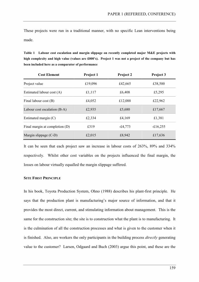
PAPER 1 (REFEREED, CONFERENCE)
159
These projects were run in a traditional manner, with no specific Lean interventions being
made.
Table 1 Labour cost escalation and margin slippage on recently completed major M&E projects with
high complexity and high value (values are £000’s). Project 1 was not a project of the company but has
been included here as a comparator of performance
Cost Element Project 1 Project 2 Project 3
Project value £19,096 £42,665 £38,500
Estimated labour cost (A) £1,117 £6,408 £5,295
Final labour cost (B) £4,052 £12,088 £22,962
Labour cost escalation (B-A) £2,935 £5,680 £17,667
Estimated margin (C) £2,334 £4,169 £1,381
Final margin at completion (D) £319 -£4,773 -£16,255
Margin slippage (C-D) £2,015 £8,942 £17,636
It can be seen that each project saw an increase in labour costs of 263%, 89% and 334%
respectively. Whilst other cost variables on the projects influenced the final margin, the
losses on labour virtually equalled the margin slippage suffered.
SITE FIRST PRINCIPLE
In his book, Toyota Production System, Ohno (1988) describes his plant-first principle. He
says that the production plant is manufacturing’s major source of information, and that it
provides the most direct, current, and stimulating information about management. This is the
same for the construction site; the site is to construction what the plant is to manufacturing. It
is the culmination of all the construction processes and what is given to the customer when it
is finished. Also, are workers the only participants in the building process directly generating
value to the customer? Larsen, Odgaard and Buch (2003) argue this point, and these are the
PAPER 1 (REFEREED, CONFERENCE)
160
reasons for the principle themes of this project. It seeks to focus on the worker, the worker’s
environment, and what makes the worker do what they do and why they do it, and will only
be concerned with M&E workers and those of key interfacing trades insofar as they apply.
The overarching aim then is to implement “Lean” in an action research project for the
company with a particular focus on the worker and their activities and behaviour. This will
be addressed through investigating three principal themes:
Practical: (sensible, useful, effective, involving, the simple basics) What people “do” at
the workplace – Standardisation of work, process and products to create flow, pull and value
delivery. This aspect of the research will seek to develop innovative methods and use of
innovative components for installation by standardising the work. Standard work is an
agreed-upon set of work procedures that establishes the best and most reliable methods and
sequences for each process and each worker (Productivity Press, 2002).
Physical: (to do with the body as opposed to the mind or spirit) How people do things in
the workplace – Ergonomics and workplace organisation to improve health, safety and
productivity. This aspect of the research will seek to address how people do things in the
workplace. Of particular interest is ergonomics, which in the industrial workplace is
generally defined as a variation of the following:
“A science devoted to determining the range of anatomical, physiological and psychological
human factors and designing work environments conducive to these ranges with the objective
of maximising productivity and minimising injury” (McNamara, 1986).
Psychological: (of or affecting the mind) Why people do what they do – Understanding
motivation of the worker and its influence on behaviour at the workplace. This aspect of the
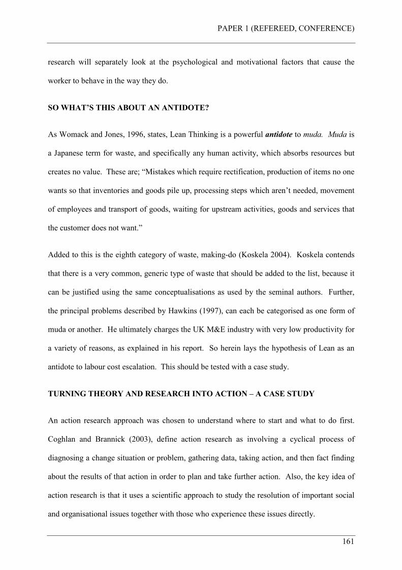
PAPER 1 (REFEREED, CONFERENCE)
161
research will separately look at the psychological and motivational factors that cause the
worker to behave in the way they do.
SO WHAT’S THIS ABOUT AN ANTIDOTE?
As Womack and Jones, 1996, states, Lean Thinking is a powerful antidote to muda. Muda is
a Japanese term for waste, and specifically any human activity, which absorbs resources but
creates no value. These are; “Mistakes which require rectification, production of items no one
wants so that inventories and goods pile up, processing steps which aren’t needed, movement
of employees and transport of goods, waiting for upstream activities, goods and services that
the customer does not want.”
Added to this is the eighth category of waste, making-do (Koskela 2004). Koskela contends
that there is a very common, generic type of waste that should be added to the list, because it
can be justified using the same conceptualisations as used by the seminal authors. Further,
the principal problems described by Hawkins (1997), can each be categorised as one form of
muda or another. He ultimately charges the UK M&E industry with very low productivity for
a variety of reasons, as explained in his report. So herein lays the hypothesis of Lean as an
antidote to labour cost escalation. This should be tested with a case study.
TURNING THEORY AND RESEARCH INTO ACTION – A CASE STUDY
An action research approach was chosen to understand where to start and what to do first.
Coghlan and Brannick (2003), define action research as involving a cyclical process of
diagnosing a change situation or problem, gathering data, taking action, and then fact finding
about the results of that action in order to plan and take further action. Also, the key idea of
action research is that it uses a scientific approach to study the resolution of important social
and organisational issues together with those who experience these issues directly.
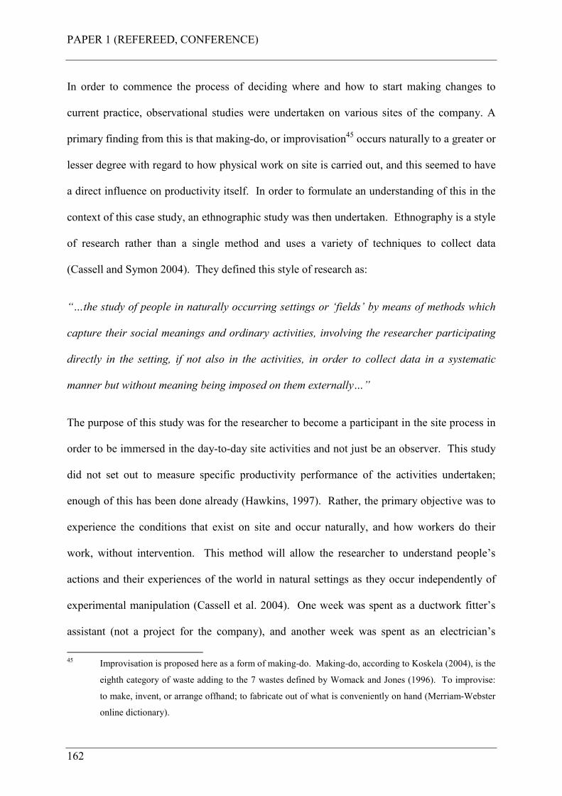
PAPER 1 (REFEREED, CONFERENCE)
162
In order to commence the process of deciding where and how to start making changes to
current practice, observational studies were undertaken on various sites of the company. A
primary finding from this is that making-do, or improvisation45 occurs naturally to a greater or
lesser degree with regard to how physical work on site is carried out, and this seemed to have
a direct influence on productivity itself. In order to formulate an understanding of this in the
context of this case study, an ethnographic study was then undertaken. Ethnography is a style
of research rather than a single method and uses a variety of techniques to collect data
(Cassell and Symon 2004). They defined this style of research as:
“…the study of people in naturally occurring settings or ‘fields’ by means of methods which
capture their social meanings and ordinary activities, involving the researcher participating
directly in the setting, if not also in the activities, in order to collect data in a systematic
manner but without meaning being imposed on them externally…”
The purpose of this study was for the researcher to become a participant in the site process in
order to be immersed in the day-to-day site activities and not just be an observer. This study
did not set out to measure specific productivity performance of the activities undertaken;
enough of this has been done already (Hawkins, 1997). Rather, the primary objective was to
experience the conditions that exist on site and occur naturally, and how workers do their
work, without intervention. This method will allow the researcher to understand people’s
actions and their experiences of the world in natural settings as they occur independently of
experimental manipulation (Cassell et al. 2004). One week was spent as a ductwork fitter’s
assistant (not a project for the company), and another week was spent as an electrician’s
45 Improvisation is proposed here as a form of making-do. Making-do, according to Koskela (2004), is the
eighth category of waste adding to the 7 wastes defined by Womack and Jones (1996). To improvise:
to make, invent, or arrange offhand; to fabricate out of what is conveniently on hand (Merriam-Webster
online dictionary).
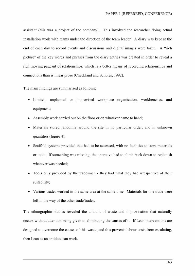
PAPER 1 (REFEREED, CONFERENCE)
163
assistant (this was a project of the company). This involved the researcher doing actual
installation work with teams under the direction of the team leader. A diary was kept at the
end of each day to record events and discussions and digital images were taken. A “rich
picture” of the key words and phrases from the diary entries was created in order to reveal a
rich moving pageant of relationships, which is a better means of recording relationships and
connections than is linear prose (Checkland and Scholes, 1992).
The main findings are summarised as follows:
• Limited, unplanned or improvised workplace organisation, workbenches, and
equipment;
• Assembly work carried out on the floor or on whatever came to hand;
• Materials stored randomly around the site in no particular order, and in unknown
quantities (figure 4);
• Scaffold systems provided that had to be accessed, with no facilities to store materials
or tools. If something was missing, the operative had to climb back down to replenish
whatever was needed;
• Tools only provided by the tradesmen - they had what they had irrespective of their
suitability;
• Various trades worked in the same area at the same time. Materials for one trade were
left in the way of the other trade/trades.
The ethnographic studies revealed the amount of waste and improvisation that naturally
occurs without attention being given to eliminating the causes of it. If Lean interventions are
designed to overcome the causes of this waste, and this prevents labour costs from escalating,
then Lean as an antidote can work.
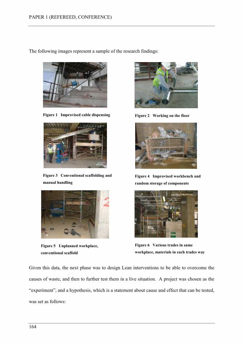
PAPER 1 (REFEREED, CONFERENCE)
164
The following images represent a sample of the research findings:
Figure 1 Improvised cable dispensing
Figure 2 Working on the floor
Figure 3 Conventional scaffolding and
manual handling
Figure 4 Improvised workbench and
random storage of components
Figure 5 Unplanned workplace,
conventional scaffold
Figure 6 Various trades in same
workplace, materials in each trades way
Given this data, the next phase was to design Lean interventions to be able to overcome the
causes of waste, and then to further test them in a live situation. A project was chosen as the
“experiment”, and a hypothesis, which is a statement about cause and effect that can be tested,
was set as follows:
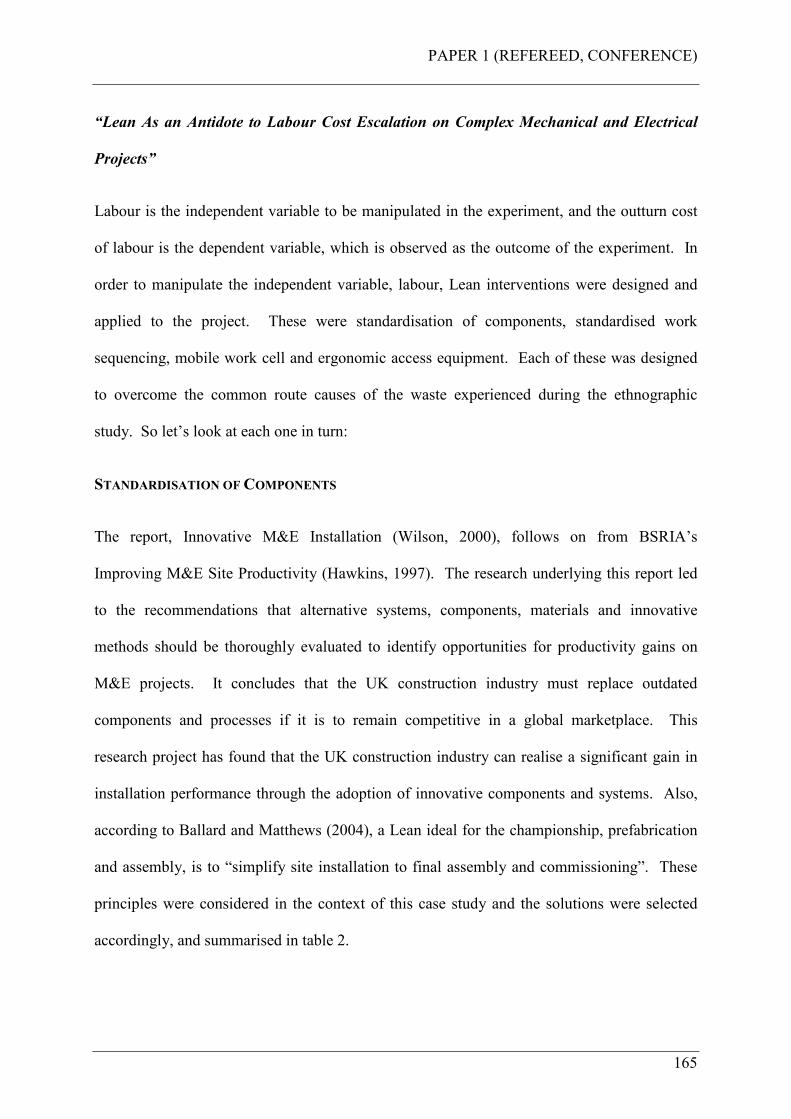
PAPER 1 (REFEREED, CONFERENCE)
165
“Lean As an Antidote to Labour Cost Escalation on Complex Mechanical and Electrical
Projects”
Labour is the independent variable to be manipulated in the experiment, and the outturn cost
of labour is the dependent variable, which is observed as the outcome of the experiment. In
order to manipulate the independent variable, labour, Lean interventions were designed and
applied to the project. These were standardisation of components, standardised work
sequencing, mobile work cell and ergonomic access equipment. Each of these was designed
to overcome the common route causes of the waste experienced during the ethnographic
study. So let’s look at each one in turn:
STANDARDISATION OF COMPONENTS
The report, Innovative M&E Installation (Wilson, 2000), follows on from BSRIA’s
Improving M&E Site Productivity (Hawkins, 1997). The research underlying this report led
to the recommendations that alternative systems, components, materials and innovative
methods should be thoroughly evaluated to identify opportunities for productivity gains on
M&E projects. It concludes that the UK construction industry must replace outdated
components and processes if it is to remain competitive in a global marketplace. This
research project has found that the UK construction industry can realise a significant gain in
installation performance through the adoption of innovative components and systems. Also,
according to Ballard and Matthews (2004), a Lean ideal for the championship, prefabrication
and assembly, is to “simplify site installation to final assembly and commissioning”. These
principles were considered in the context of this case study and the solutions were selected
accordingly, and summarised in table 2.

PAPER 1 (REFEREED, CONFERENCE)
166
Table 2 Solutions selected in accordance with installation activity and benefits derived from the solution
(terminology for benefits is as used in Wilson (2000), Innovative M&E Installation)
Activity Solution selected Benefit of solution
Connection to the structure Shot fixing system Increased productivity
Method of support /
suspension
Pre-assembled, integrated supports Integrated system; increased
productivity
Means of connecting service
to support
Lightweight, fast assembly channel
system; quick fit support components,
pipe-clips etc.
Increased productivity;
material savings; ease of
installation
System installation Press-fit pipework and conduit systems Increased productivity; ease
of installation
Tools and equipment Cordless power tools; mobile work cell
and ergonomic scaffold system
Increased productivity;
improved working practices
The specific purpose of this intervention was to eliminate unnecessary site processing of
materials and fittings.
STANDARDISED WORK SEQUENCING
A “Week-Beat” system of structuring the work was employed, where the building was
divided into smaller work zones (approx 1,000m2) and sequenced a “parade of trades”
through each zone. Each trade was provided a period of one week in each zone to complete
their work. This is as described by Horman et al (2002) as short interval production
scheduling (SIPS). The specific purpose of this intervention was to eliminate the situation
whereby materials and access equipment for one trade interferes with another, and tradesmen
are fighting for the same workplace.
MOBILE WORK CELL
Santos et al (2002) described applying the concept of mobile cell manufacturing in
construction. This paper presents the results of an exploratory study investigating the
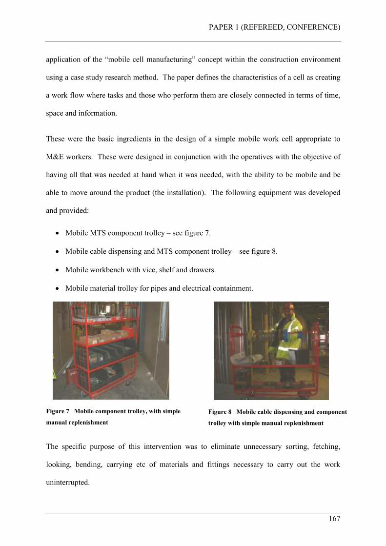
PAPER 1 (REFEREED, CONFERENCE)
167
application of the “mobile cell manufacturing” concept within the construction environment
using a case study research method. The paper defines the characteristics of a cell as creating
a work flow where tasks and those who perform them are closely connected in terms of time,
space and information.
These were the basic ingredients in the design of a simple mobile work cell appropriate to
M&E workers. These were designed in conjunction with the operatives with the objective of
having all that was needed at hand when it was needed, with the ability to be mobile and be
able to move around the product (the installation). The following equipment was developed
and provided:
• Mobile MTS component trolley – see figure 7.
• Mobile cable dispensing and MTS component trolley – see figure 8.
• Mobile workbench with vice, shelf and drawers.
• Mobile material trolley for pipes and electrical containment.
Figure 7 Mobile component trolley, with simple
manual replenishment
Figure 8 Mobile cable dispensing and component
trolley with simple manual replenishment
The specific purpose of this intervention was to eliminate unnecessary sorting, fetching,
looking, bending, carrying etc of materials and fittings necessary to carry out the work
uninterrupted.
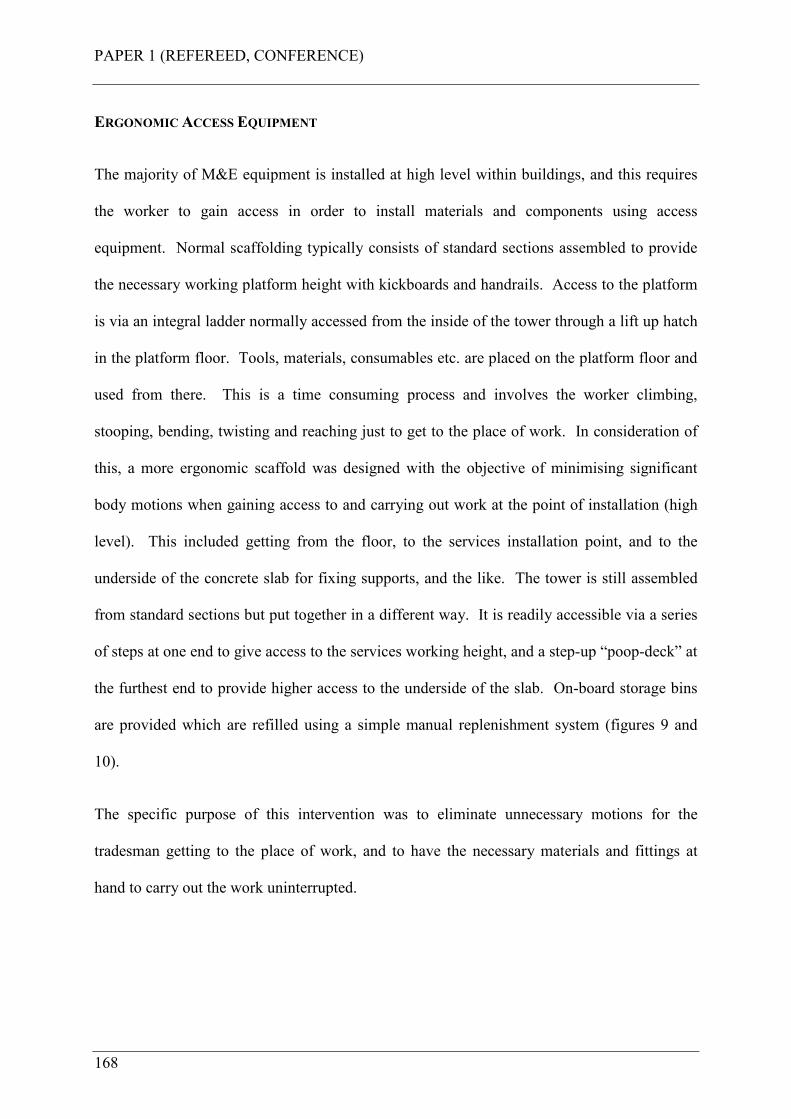
PAPER 1 (REFEREED, CONFERENCE)
168
ERGONOMIC ACCESS EQUIPMENT
The majority of M&E equipment is installed at high level within buildings, and this requires
the worker to gain access in order to install materials and components using access
equipment. Normal scaffolding typically consists of standard sections assembled to provide
the necessary working platform height with kickboards and handrails. Access to the platform
is via an integral ladder normally accessed from the inside of the tower through a lift up hatch
in the platform floor. Tools, materials, consumables etc. are placed on the platform floor and
used from there. This is a time consuming process and involves the worker climbing,
stooping, bending, twisting and reaching just to get to the place of work. In consideration of
this, a more ergonomic scaffold was designed with the objective of minimising significant
body motions when gaining access to and carrying out work at the point of installation (high
level). This included getting from the floor, to the services installation point, and to the
underside of the concrete slab for fixing supports, and the like. The tower is still assembled
from standard sections but put together in a different way. It is readily accessible via a series
of steps at one end to give access to the services working height, and a step-up “poop-deck” at
the furthest end to provide higher access to the underside of the slab. On-board storage bins
are provided which are refilled using a simple manual replenishment system (figures 9 and
10).
The specific purpose of this intervention was to eliminate unnecessary motions for the
tradesman getting to the place of work, and to have the necessary materials and fittings at
hand to carry out the work uninterrupted.
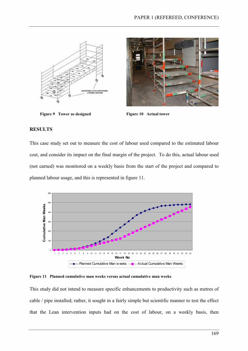
PAPER 1 (REFEREED, CONFERENCE)
169
Figure 9 Tower as designed
Figure 10 Actual tower
RESULTS
This case study set out to measure the cost of labour used compared to the estimated labour
cost, and consider its impact on the final margin of the project. To do this, actual labour used
(not earned) was monitored on a weekly basis from the start of the project and compared to
planned labour usage, and this is represented in figure 11.
0
100
200
300
400
500
600
1 2 3 4 5 6 7 8 9 10 11 12 13 14 15 16 17 18 19 20 21 22 23 24 25 26 27 28 29 30 31 32 33 34
Week No
Cumulative Man W
eeks
Planned Cumulative Man w eeks Actual Cumulative Man Weeks
Figure 11 Planned cumulative man weeks versus actual cumulative man weeks
This study did not intend to measure specific enhancements to productivity such as metres of
cable / pipe installed; rather, it sought in a fairly simple but scientific manner to test the effect
that the Lean intervention inputs had on the cost of labour, on a weekly basis, then
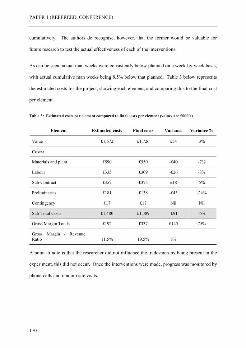
PAPER 1 (REFEREED, CONFERENCE)
170
cumulatively. The authors do recognise, however, that the former would be valuable for
future research to test the actual effectiveness of each of the interventions.
As can be seen, actual man weeks were consistently below planned on a week-by-week basis,
with actual cumulative man weeks being 8.5% below that planned. Table 3 below represents
the estimated costs for the project, showing each element, and comparing this to the final cost
per element.
Table 3: Estimated costs per element compared to final costs per element (values are £000’s)
Element Estimated costs Final costs Variance Variance %
Value £1,672 £1,726 £54 3%
Costs:
Materials and plant £590 £550 -£40 -7%
Labour £335 £309 -£26 -8%
Sub-Contract £357 £375 £18 5%
Preliminaries £181 £138 -£43 -24%
Contingency £17 £17 Nil Nil
Sub-Total Costs £1,480 £1,389 -£91 -6%
Gross Margin Totals £192 £337 £145 75%
Gross Margin / Revenue
Ratio 11.5% 19.5% 8%
A point to note is that the researcher did not influence the tradesmen by being present in the
experiment, this did not occur. Once the interventions were made, progress was monitored by
phone-calls and random site visits.
PAPER 1 (REFEREED, CONFERENCE)
171
DISCUSSION
Table 3 shows that the project ended with a 7% saving in materials and plant, an 8% saving in
labour, a 5% increase in sub-contract costs and a 24% saving in preliminaries. Overall the
project had a cost saving of £91k, which resulted in a margin increase of £144k, contributed
too also by an increase in value from the customer of £53K.
Under normal experimental conditions, it would have been desirable to compare these results
with those of a control experiment, where the hypothesised cause was absent. In other words,
to observe an exact same project that runs at exactly the same time but without the Lean
interventions being made. However, in the context of operating in a live business and with a
live project it was not possible to do so. The historic projects shown in table 1 represent the
control group which did not have Lean interventions imposed upon them, the cause, but had
the result of substantially increased labour costs, the effect, contributing to severe margin
slippage. What this experiment has shown is that the four interventions proved effective in
enhancing productivity, and the outcome in terms of reduced labour costs seems to be a
function of these inputs. Did, therefore, these interventions eliminate the route causes of
waste that would have otherwise occurred naturally? It would appear so. Labour costs did
not escalate and margin slippage did not occur, in fact the margin increased significantly on
the case study project.
It could be argued that the project improved its financial outcome because of skilled project
management, a good estimate, a better client, or better contractors in the other trades etc. This
cannot be substantiated in the context of this study. But given that the company has
experienced increased labour costs where interventions were not made, the results of this
experiment are an encouraging step in its performance improvement initiative, by showing

PAPER 1 (REFEREED, CONFERENCE)
172
positive results in its first endeavours. So, is “Lean” an antidote to labour cost escalation on
complex M&E projects as hypothesised, and did this lead to preventing margin slippage? The
authors would argue yes, it is, and yes, probably it did. They also recognise that other cost
variables need to be controlled which deserve equal attention in the future. But the final
reminder is that this research set out to focus on the labour element only, this being the
company’s biggest current concern. This research has investigated the practical and physical
themes of the overall research project. The psychological theme, although partly experienced
during the ethnographic study, was not investigated.
FURTHER RESEARCH
These interventions were the first stage of designing and implementing a Lean Construction
System for the company. The findings from this report will be used to inform and develop
standardised operating procedures and routines for how work will be conducted in the future
on new projects. This will be together with new Lean features yet to be researched,
developed, implemented and tested on these new projects, which will be reported on in the
future. One aspect of this will be psychological factors that influence the worker. This was
not considered as part of this case study, but is one of the main themes for the research
project.
REFERENCES
Ballard, G. and Matthews, O., (2004). Championship – prefabrication and assembly.
Proceedings of the 12th annual conference of the International Group for Lean
Construction, Elsinore, Denmark, August 3-5, 2004.
Cassell, C. and Symon, G., (2004). Essential guide to qualitative methods in organisational
research. SAGE publications.
PAPER 1 (REFEREED, CONFERENCE)
173
Checkland, P. and Scholes, J., (1992). Soft systems methodology in action. Wiley
Publications, UK.
Coghlan, D. and Brannick, T., (2003). Doing action research in your own organisation.
SAGE publications, UK.
Gibb, A.G.F. and Isack, F. (2003). Re-engineering through pre-assembly: client expectations
and drivers. Building Research and Information, 31 (2), 146-160.
Hawkins, G., (1997). Improving M&E site productivity, BSRIA technical note TN 14/97,
The Building Services Research and Information Association, Bracknell, UK.
Horman, M.J., Messner, J.I., Riley, D.R., Pulaski, M.H., (2003). Using buffers to manage
production: a case study of the pentagon renovation project. Proceedings of the 11th
annual conference of the International Group for Lean Construction, Blacksburg,
Virginia, July 22-24, 2003.
Koskela, L., (2004). Making-do – the eighth category of waste. Proceedings of the 12th
annual conference of the International Group for Lean Construction, Elsinore,
Denmark, August 3-5, 2004.
Larsen, J., Odgaard, G., and Buch, S., (2003). A trade union’s view of the building process.
Proceedings of the 11th annual conference of the International Group for Lean
Construction, Blacksburg, Virginia, July 22-24, 2003.
McNamara, Brian E (1986). Ergonomics: maximising the human resource. 1986 Logistex
Forum, May 6-8, 1986.
PAPER 1 (REFEREED, CONFERENCE)
174
Ohno, T., (1988). Toyota Production System, beyond large scale production. Productivity
Press, USA.
Santos, A., Moser, L., Tookey, J., (2002). Applying the concept of mobile cell manufacturing
on the drywall process. Proceedings of the 10th annual conference of the International
Group for Lean Construction, Gramado, Brazil.
The Productivity Press Development team (2002). Standard work for the shopfloor.
Productivity Press.
Wilson, D., (2000). Innovative M&E installation, BSRIA ACT 9/2000, The Building Services
Research and Information Association, Bracknell, UK.
Womack, J.P. and Jones, D.T., (1996). Lean Thinking, banish waste and create wealth in your
organisation. Simon and Schuster, UK.
PAPER 2 (REFEREED, CONFERENCE)
175
APPENDIX B PAPER 2 (REFEREED, CONFERENCE)
Court, P., Pasquire, C., Gibb, A.G.F., and Bower, D., (2006). “Design of a Lean and Agile
Construction System for a Large and Complex Mechanical and Electrical Project.”
Proceedings of the 14th annual conference of the International Group for Lean Construction,
Santiago, Chile, 2006.

PAPER 2 (REFEREED, CONFERENCE)
176
PAPER 2 (REFEREED, CONFERENCE)
177
DESIGN OF A LEAN AND AGILE CONSTRUCTION SYSTEM
FOR A LARGE AND COMPLEX MECHANICAL AND
ELECTRICAL PROJECT
Peter Court, Christine Pasquire, Alistair Gibb, David Bower
ABSTRACT
This paper represents “work-in-progress” as part of a collaborative research project being
undertaken at the Centre for Innovative Collaborative Engineering for an Engineering
Doctorate at Loughborough University, UK. The programme is funded by the EPSRC and is
sponsored by a major UK mechanical and electrical contractor (the sponsor company). The
project will have specific objectives, which will be capable of making a significant
contribution to the performance of the company. The sponsor company is developing a
“Construction System” in order to improve the performance of its projects, and earlier
research in this field has shown that Lean interventions, when applied to a case study project,
have had positive results. This paper describes the next phase of the development of the
Construction System, and proposes a Lean and agile production system model which is to be
implemented on a major private finance initiative (PFI) hospital development, and in
particular the mechanical and electrical (M&E) elements. The model builds upon a “leagile”
concept developed from manufacturing theory, and shows how the need for Leanness and
agility depends upon a total supply chain and labour strategy.
PAPER 2 (REFEREED, CONFERENCE)
178
KEY WORDS
Construction System, performance improvement, Lean interventions, Lean and agile,
mechanical and electrical, leagile, total supply chain, labour.
INTRODUCTION
This paper represents “work-in-progress” as part of a collaborative research project being
undertaken at the Centre for Innovative Construction Engineering for an Engineering
Doctorate at Loughborough University, UK. The programme is funded by the EPSRC and is
sponsored by a major UK mechanical and electrical contractor (the company). The project
will have specific objectives, which will be capable of making a significant contribution to the
performance of the company.
The themes of the research project are “Innovative Construction Technologies” driven by the
desire to use leading edge research and learning to improve the business of the sponsoring
company. The sponsor company is a major provider of advanced mechanical, electrical and
communications solutions in the construction sector in the UK. It works for customers in
banking, retail, leisure and commercial property development, as well as education, health,
defence and government offices, secure establishments and airports.
RESEARCH PROJECT OBJECTIVE
To be clear about the objective of this project, it is about improving site operations, making
them safer for the worker, and improving efficiency and productivity. Since previous
research was conducted (Court et al. 2005), an Incident and Injury Free programme has been
introduced into the company. The safety leadership team state that the company is prepared
to invest whatever is necessary to drive improvement in health and safety to ensure everybody
PAPER 2 (REFEREED, CONFERENCE)
179
returns home safely. “Failure to do so renders the company valueless.” Also, the company is
embarking on a programme of improving the performance of its projects by the introduction
of a “project delivery standard.” One component of this standard is to “adopt Lean and agile
processes to compete with the worlds leading businesses.” From this, it can be seen that the
key elements to focus upon as further research project objectives are:
1. Everyone is to return home safely (from the construction site)
2. To adopt Lean and agile processes to compete46 with the worlds leading businesses
Everyone returning home safely cannot just mean preventing incidents and injury in the
traditional sense. It must also mean good ergonomics for the worker. Ergonomics, which in
the industrial workplace is generally defined as a variation of the following:
“A science devoted to determining the range of anatomical, physiological and psychological
human factors and designing work environments conducive to these ranges with the objective
of maximising productivity and minimising injury” (McNamara, 1986). It is expected also,
that by adopting Lean and agile processes a state of competiveness will occur. This is
interpreted as putting the company ahead of its competitors in terms of profitability and
position in the marketplace47.
Manufacturing is seen as a rich source of research for Lean and agile concepts, so this was a
primary source of research data for this project, as will be shown. This project therefore has
the objective of designing and implementing a way of working on site that will satisfy these
company objectives; to be Incident and Injury Free and to adopt Lean and agile processes to
compete with the worlds leading businesses. Earlier research in this field has shown that
46 To compete: To strive consciously or unconsciously for an objective (as position, profit, or a prize): be
in a state of rivalry (Merriam-Webster online dictionary)
47 Source: The Company.
PAPER 2 (REFEREED, CONFERENCE)
180
Lean interventions, when applied to a case study project, have had positive results (Court et
al. 2005). These interventions were to form part of the design of a “Construction System”,
which is based on leading edge research and learning.
This paper describes the next phase of the development of the Construction System, and
proposes a Lean and agile Construction System model which is to be implemented on a major
private finance initiative (PFI) hospital development, and in particular the mechanical and
electrical element and the associated interfacing trades. The model builds upon a “leagile”
concept developed from manufacturing theory, and shows how the need for Leanness and
agility depends upon a total supply chain and labour strategy.
UNDERPINNING THEORY
The next phase of the research project has focussed on research and learning from
manufacturing, and in particular, Lean and agile theory. This enables a strong fit and even an
interpretation of what adopting Lean and agile processes actually means, and then preparing
to put this into practice in the real world. The research and learning undertaken has been used
to develop a Construction System model that incorporates manufacturing techniques such as;
leagility, modular assembly, reflective manufacture, ABC inventory system and pulse-driven
scheduling. The boundaries of the production system model will be described, and its
applicability to a large complex mechanical and electrical project. The expected benefits to
the company as a result of this research project will also be described. In order to gain an
understanding of the development of the model, the underpinning manufacturing theory will
be described, together with further data collected necessary to aid the design and development
of the Construction System. The Construction System itself will then be described.
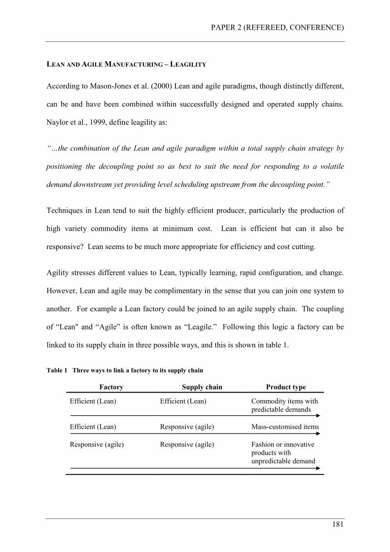
PAPER 2 (REFEREED, CONFERENCE)
181
LEAN AND AGILE MANUFACTURING – LEAGILITY
According to Mason-Jones et al. (2000) Lean and agile paradigms, though distinctly different,
can be and have been combined within successfully designed and operated supply chains.
Naylor et al., 1999, define leagility as:
“…the combination of the Lean and agile paradigm within a total supply chain strategy by
positioning the decoupling point so as best to suit the need for responding to a volatile
demand downstream yet providing level scheduling upstream from the decoupling point.”
Techniques in Lean tend to suit the highly efficient producer, particularly the production of
high variety commodity items at minimum cost. Lean is efficient but can it also be
responsive? Lean seems to be much more appropriate for efficiency and cost cutting.
Agility stresses different values to Lean, typically learning, rapid configuration, and change.
However, Lean and agile may be complimentary in the sense that you can join one system to
another. For example a Lean factory could be joined to an agile supply chain. The coupling
of “Lean" and “Agile” is often known as “Leagile.” Following this logic a factory can be
linked to its supply chain in three possible ways, and this is shown in table 1.
Table 1 Three ways to link a factory to its supply chain
Factory Supply chain Product type
Efficient (Lean) Efficient (Lean) Commodity items with
predictable demands
Efficient (Lean) Responsive (agile) Mass-customised items
Responsive (agile) Responsive (agile) Fashion or innovative
products with
unpredictable demand
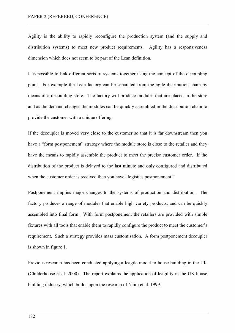
PAPER 2 (REFEREED, CONFERENCE)
182
Agility is the ability to rapidly reconfigure the production system (and the supply and
distribution systems) to meet new product requirements. Agility has a responsiveness
dimension which does not seem to be part of the Lean definition.
It is possible to link different sorts of systems together using the concept of the decoupling
point. For example the Lean factory can be separated from the agile distribution chain by
means of a decoupling store. The factory will produce modules that are placed in the store
and as the demand changes the modules can be quickly assembled in the distribution chain to
provide the customer with a unique offering.
If the decoupler is moved very close to the customer so that it is far downstream then you
have a “form postponement” strategy where the module store is close to the retailer and they
have the means to rapidly assemble the product to meet the precise customer order. If the
distribution of the product is delayed to the last minute and only configured and distributed
when the customer order is received then you have “logistics postponement.”
Postponement implies major changes to the systems of production and distribution. The
factory produces a range of modules that enable high variety products, and can be quickly
assembled into final form. With form postponement the retailers are provided with simple
fixtures with all tools that enable them to rapidly configure the product to meet the customer’s
requirement. Such a strategy provides mass customisation. A form postponement decoupler
is shown in figure 1.
Previous research has been conducted applying a leagile model to house building in the UK
(Childerhouse et al. 2000). The report explains the application of leagility in the UK house
building industry, which builds upon the research of Naim et al. 1999.
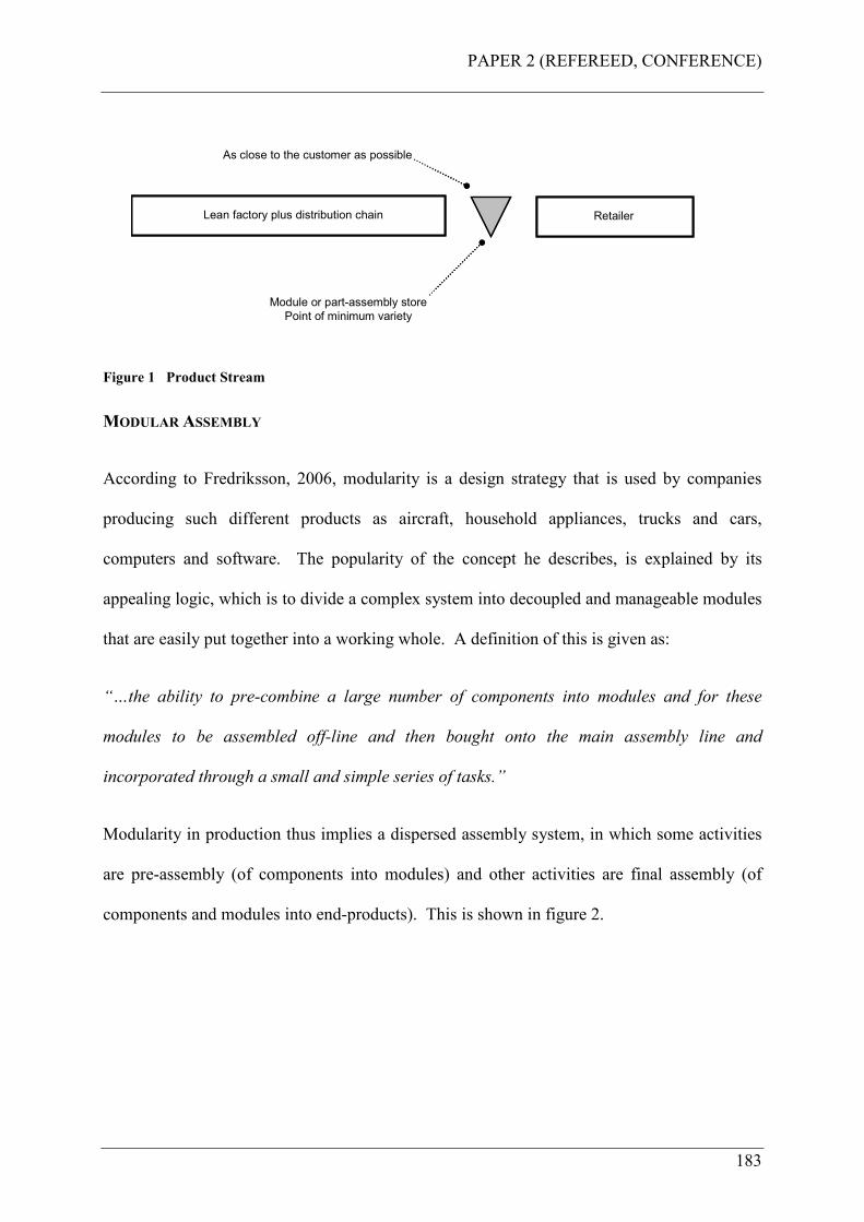
PAPER 2 (REFEREED, CONFERENCE)
183
Lean factory plus distribution chain Retailer
Module or part-assembly store
Point of minimum variety
As close to the customer as possible
Lean factory plus distribution chain Retailer
Module or part-assembly store
Point of minimum variety
As close to the customer as possible
Figure 1 Product Stream
MODULAR ASSEMBLY
According to Fredriksson, 2006, modularity is a design strategy that is used by companies
producing such different products as aircraft, household appliances, trucks and cars,
computers and software. The popularity of the concept he describes, is explained by its
appealing logic, which is to divide a complex system into decoupled and manageable modules
that are easily put together into a working whole. A definition of this is given as:
“…the ability to pre-combine a large number of components into modules and for these
modules to be assembled off-line and then bought onto the main assembly line and
incorporated through a small and simple series of tasks.”
Modularity in production thus implies a dispersed assembly system, in which some activities
are pre-assembly (of components into modules) and other activities are final assembly (of
components and modules into end-products). This is shown in figure 2.
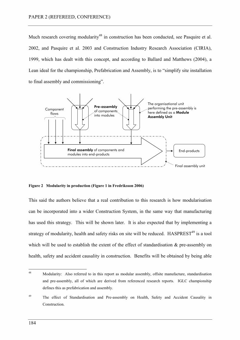
PAPER 2 (REFEREED, CONFERENCE)
184
Much research covering modularity48 in construction has been conducted, see Pasquire et al.
2002, and Pasquire et al. 2003 and Construction Industry Research Association (CIRIA),
1999, which has dealt with this concept, and according to Ballard and Matthews (2004), a
Lean ideal for the championship, Prefabrication and Assembly, is to “simplify site installation
to final assembly and commissioning”.
End-productsFinal assembly of components and modules into end-products
The organisational unit performing the pre-assembly is here defined as a Module Assembly Unit
Componentflows
Pre-assemblyof components into modules
Final assembly unit
Figure 2 Modularity in production (Figure 1 in Fredriksson 2006)
This said the authors believe that a real contribution to this research is how modularisation
can be incorporated into a wider Construction System, in the same way that manufacturing
has used this strategy. This will be shown later. It is also expected that by implementing a
strategy of modularity, health and safety risks on site will be reduced. HASPREST49 is a tool
which will be used to establish the extent of the effect of standardisation & pre-assembly on
health, safety and accident causality in construction. Benefits will be obtained by being able
48 Modularity: Also referred to in this report as modular assembly, offsite manufacture, standardisation
and pre-assembly, all of which are derived from referenced research reports. IGLC championship
defines this as prefabrication and assembly.
49 The effect of Standardisation and Pre-assembly on Health, Safety and Accident Causality in
Construction.
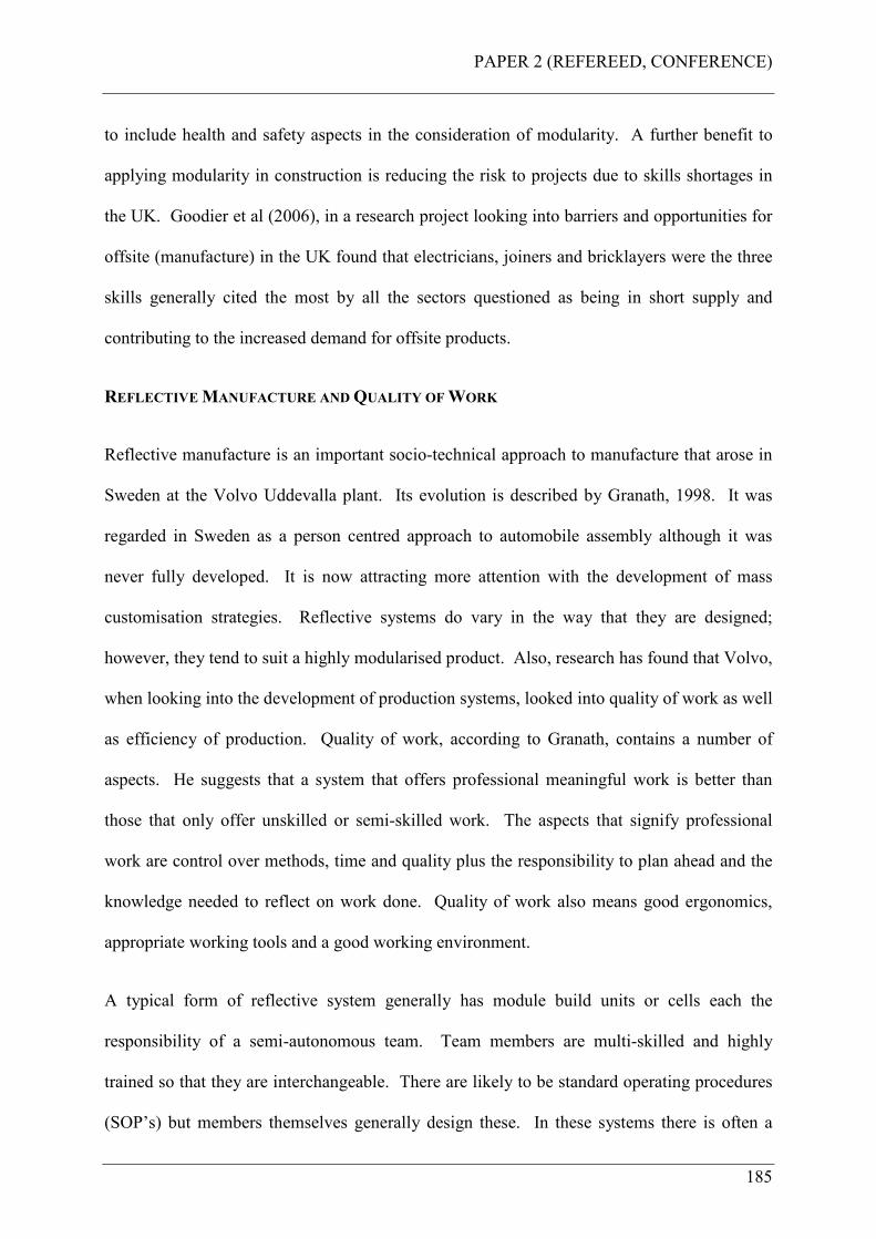
PAPER 2 (REFEREED, CONFERENCE)
185
to include health and safety aspects in the consideration of modularity. A further benefit to
applying modularity in construction is reducing the risk to projects due to skills shortages in
the UK. Goodier et al (2006), in a research project looking into barriers and opportunities for
offsite (manufacture) in the UK found that electricians, joiners and bricklayers were the three
skills generally cited the most by all the sectors questioned as being in short supply and
contributing to the increased demand for offsite products.
REFLECTIVE MANUFACTURE AND QUALITY OF WORK
Reflective manufacture is an important socio-technical approach to manufacture that arose in
Sweden at the Volvo Uddevalla plant. Its evolution is described by Granath, 1998. It was
regarded in Sweden as a person centred approach to automobile assembly although it was
never fully developed. It is now attracting more attention with the development of mass
customisation strategies. Reflective systems do vary in the way that they are designed;
however, they tend to suit a highly modularised product. Also, research has found that Volvo,
when looking into the development of production systems, looked into quality of work as well
as efficiency of production. Quality of work, according to Granath, contains a number of
aspects. He suggests that a system that offers professional meaningful work is better than
those that only offer unskilled or semi-skilled work. The aspects that signify professional
work are control over methods, time and quality plus the responsibility to plan ahead and the
knowledge needed to reflect on work done. Quality of work also means good ergonomics,
appropriate working tools and a good working environment.
A typical form of reflective system generally has module build units or cells each the
responsibility of a semi-autonomous team. Team members are multi-skilled and highly
trained so that they are interchangeable. There are likely to be standard operating procedures
(SOP’s) but members themselves generally design these. In these systems there is often a
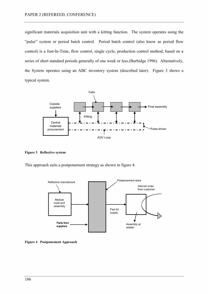
PAPER 2 (REFEREED, CONFERENCE)
186
significant materials acquisition unit with a kitting function. The system operates using the
“pulse” system or period batch control. Period batch control (also know as period flow
control) is a Just-In-Time, flow control, single cycle, production control method, based on a
series of short standard periods generally of one week or less.(Burbidge 1996). Alternatively,
the System operates using an ABC inventory system (described later). Figure 3 shows a
typical system.
Final assembly
Kitting
Outside
suppliers
Pulse-driven
AGV Loop
Cells
Central
materials
procurement
Final assembly
Kitting
Outside
suppliers
Pulse-driven
AGV Loop
Cells
Central
materials
procurement
Figure 3 Reflective system
This approach suits a postponement strategy as shown in figure 4.
Module
build and
assembly
Postponement store
Fast kit
supply
Parts from
suppliers
Reflective manufacture
Assembly at
retailer
Internet order
from customer
Module
build and
assembly
Postponement store
Fast kit
supply
Parts from
suppliers
Reflective manufacture
Assembly at
retailer
Internet order
from customer
Figure 4 Postponement Approach

PAPER 2 (REFEREED, CONFERENCE)
187
ABC INVENTORY SYSTEM
ABC analysis is based on Pareto analysis or the 80/20 rule. In inventory control 80% of the
items need 20% of the attention, while the remaining 20% need 80% of the attention. They
are categorised as follows: A items are expensive, critical and needing special care
(modules). B items need just standard care (components). C items need little care
(consumables such as nuts, bolts, washers etc). It is common to use different control
strategies for the A, B and C parts. The control strategy depends upon the product complexity
and the nature of demand, but typically: A parts are ordered using a “call-off” system. B
parts are ordered conventionally using an MRP system. C parts are ordered using a simple
inventory management system like the two bin kanban system.
FURTHER DATA COLLECTION
During the course of the design of the Construction System, further data was collected for the
design of trade team specific mobile work cells. This was conducted in a focus group session
with representatives from electrical workers, mechanical pipe workers, and duct workers. A
focus group is a form of qualitative research in which a group of people are asked about their
attitude towards a product, concept, advertisement, idea, or packaging. Questions are asked in
an interactive group setting where participants are free to talk with other group members. In
the world of marketing, focus groups are an important tool for acquiring feedback regarding
new products, as well as various topics. In particular, focus groups allow companies wishing
to develop, package, name, or test market a new product, to discuss, view, and/or test the new
product before it is made available to the public. This can provide invaluable information
about the potential market acceptance of the product.
PAPER 2 (REFEREED, CONFERENCE)
188
The aim of the focus group session was to identify the complete kit required for each specific
task to be completed at each stage of the site operation, with everything that is needed,
factoring in: access and egress to and from the workplace, access equipment, tools, personal
protective equipment, materials handling devices, and task lighting etc. It also included
discussions on how material flows should be conducted on site, to the point of use. This data
was collated and used to design trade team specific mobile work cells, and the work system
itself. This builds upon the previous research (Court et al. 2005), implementing mobile work
cells and ergonomic access equipment designed and used in a case study project.
In order to formulate an understanding of manufacturing concepts in the context of this
research, an ethnographic study was undertaken. Ethnography is a style of research rather
than a single method and uses a variety of techniques to collect data, (Cassell et al. 2004).
This was an observational study conducted at the BMW “Mini” factory in Cowley, UK. This
was to observe the assembly of the car body and the final car assembly process, to give the
authors a “feel” for the manufacturing and assembly environment, and how people worked. It
is not meant here to expand upon the Mini manufacturing process, but more importantly, the
authors, by observing the various assembly processes conducted either by robots or people
were able to get many visual clues as to how the techniques could be transferred to the
Construction System model.
THE CONSTRUCTION SYSTEM
Previous research by the authors, Court et al. 2005, found that Lean interventions, when
applied to a case study project, had positive results in terms of improving the performance of
the project. These interventions were the first stage of designing and implementing a
Construction System for the company. The findings from this research were to be used to
inform and develop standardised operating procedures and routines for how work will be
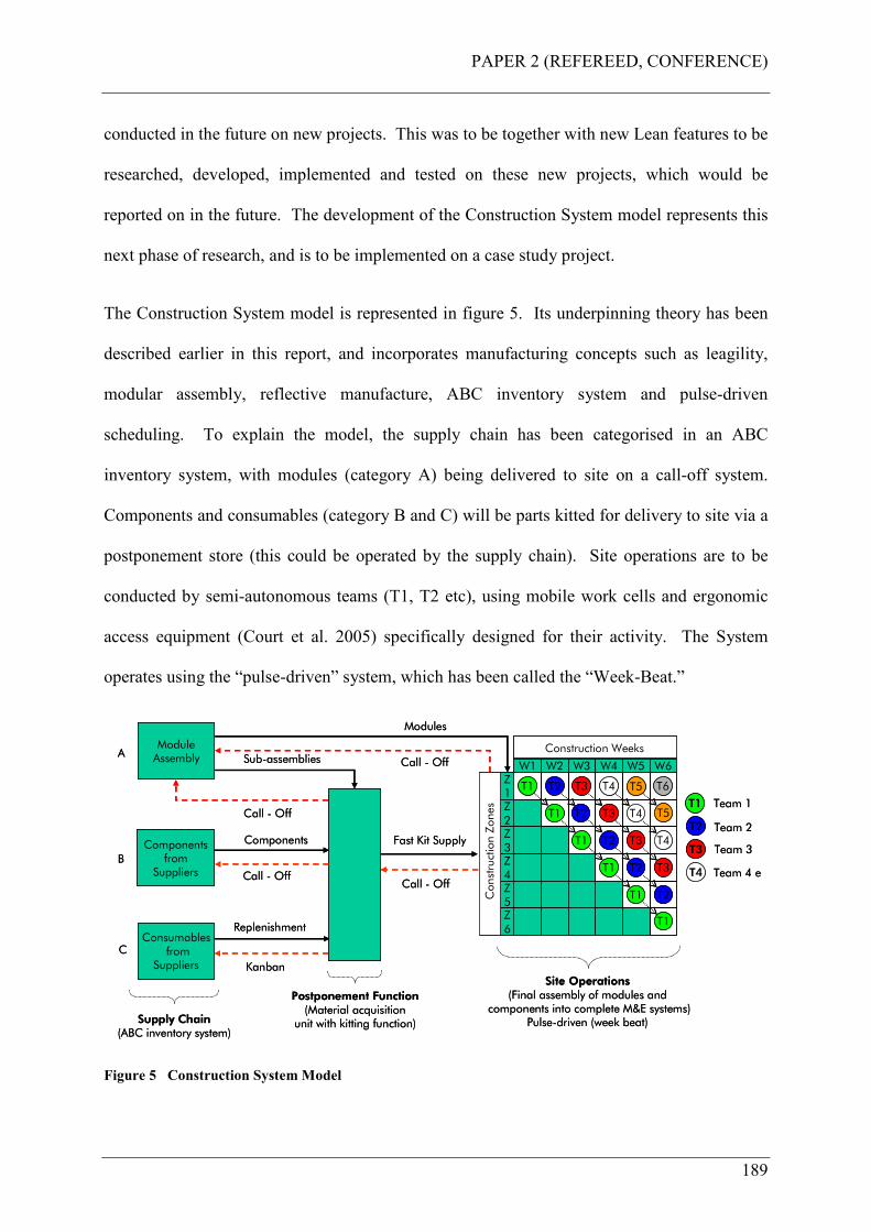
PAPER 2 (REFEREED, CONFERENCE)
189
conducted in the future on new projects. This was to be together with new Lean features to be
researched, developed, implemented and tested on these new projects, which would be
reported on in the future. The development of the Construction System model represents this
next phase of research, and is to be implemented on a case study project.
The Construction System model is represented in figure 5. Its underpinning theory has been
described earlier in this report, and incorporates manufacturing concepts such as leagility,
modular assembly, reflective manufacture, ABC inventory system and pulse-driven
scheduling. To explain the model, the supply chain has been categorised in an ABC
inventory system, with modules (category A) being delivered to site on a call-off system.
Components and consumables (category B and C) will be parts kitted for delivery to site via a
postponement store (this could be operated by the supply chain). Site operations are to be
conducted by semi-autonomous teams (T1, T2 etc), using mobile work cells and ergonomic
access equipment (Court et al. 2005) specifically designed for their activity. The System
operates using the “pulse-driven” system, which has been called the “Week-Beat.”
Supply Chain(ABC inventory system)
ModuleAssembly
Componentsfrom
Suppliers
Consumablesfrom
Suppliers
A
B
C
Supply Chain(ABC inventory system)
ModuleAssembly
Componentsfrom
Suppliers
Consumablesfrom
Suppliers
A
B
C
W1 W2 W3 W4 W5 W6Z1Z2Z3Z4Z5Z6
T1 T2 T3 T4
T1 T2
T1 T2
T3
T1
T1
T1
T2
T2
T3
T3
T4
T4
Construction Zones
Construction Weeks
T5
T5
T6
T3
T4
Team 1
Team 2
Team 3
Team 4 etc
T1
T2
Site Operations(Final assembly of modules and
components into complete MDE systems)Pulse-driven (week beat)
Call - Off
Fast Kit Supply
Call - Off
Modules
Call - Off
Components
Kanban
Postponement Function(Material acquisition
unit with kitting function)
Replenishment
Sub-assemblies
Call - Off
Call - Off
Components
Kanban
Postponement Function(Material acquisition
unit with kitting function)
Replenishment
Sub-assemblies
Call - Off
Figure 5 Construction System Model
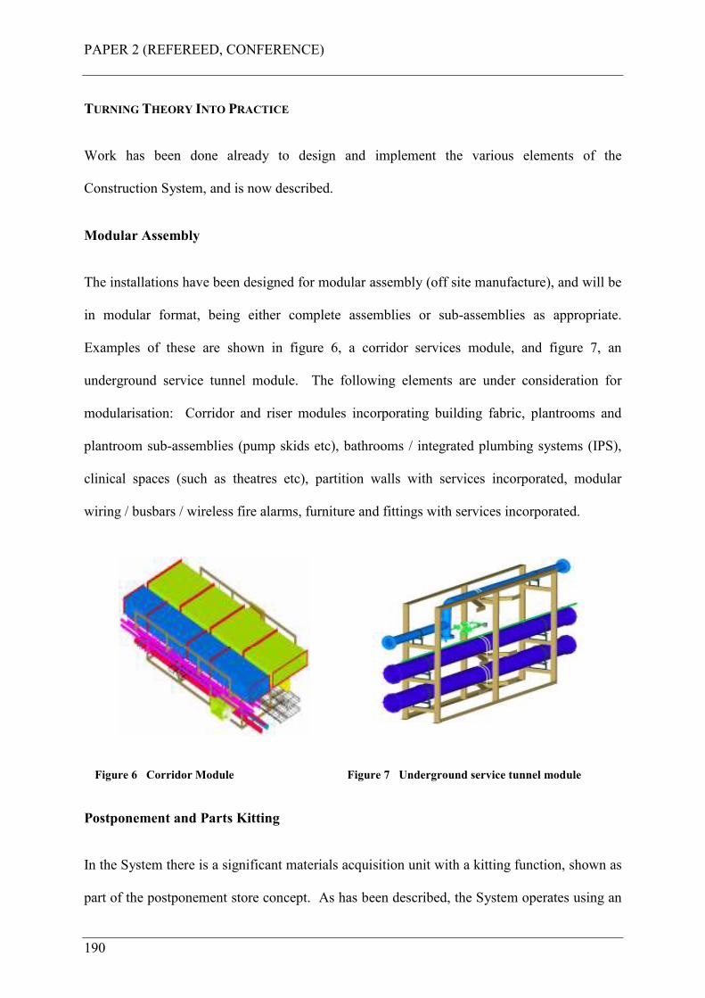
PAPER 2 (REFEREED, CONFERENCE)
190
TURNING THEORY INTO PRACTICE
Work has been done already to design and implement the various elements of the
Construction System, and is now described.
Modular Assembly
The installations have been designed for modular assembly (off site manufacture), and will be
in modular format, being either complete assemblies or sub-assemblies as appropriate.
Examples of these are shown in figure 6, a corridor services module, and figure 7, an
underground service tunnel module. The following elements are under consideration for
modularisation: Corridor and riser modules incorporating building fabric, plantrooms and
plantroom sub-assemblies (pump skids etc), bathrooms / integrated plumbing systems (IPS),
clinical spaces (such as theatres etc), partition walls with services incorporated, modular
wiring / busbars / wireless fire alarms, furniture and fittings with services incorporated.
Figure 6 Corridor Module Figure 7 Underground service tunnel module
Postponement and Parts Kitting
In the System there is a significant materials acquisition unit with a kitting function, shown as
part of the postponement store concept. As has been described, the System operates using an
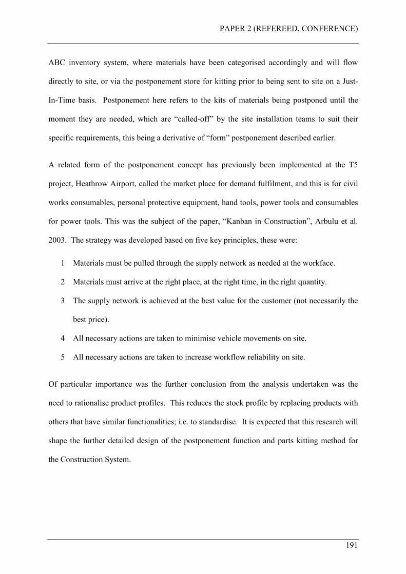
PAPER 2 (REFEREED, CONFERENCE)
191
ABC inventory system, where materials have been categorised accordingly and will flow
directly to site, or via the postponement store for kitting prior to being sent to site on a Just-
In-Time basis. Postponement here refers to the kits of materials being postponed until the
moment they are needed, which are “called-off” by the site installation teams to suit their
specific requirements, this being a derivative of “form” postponement described earlier.
A related form of the postponement concept has previously been implemented at the T5
project, Heathrow Airport, called the market place for demand fulfilment, and this is for civil
works consumables, personal protective equipment, hand tools, power tools and consumables
for power tools. This was the subject of the paper, “Kanban in Construction”, Arbulu et al.
2003. The strategy was developed based on five key principles, these were:
1 Materials must be pulled through the supply network as needed at the workface.
2 Materials must arrive at the right place, at the right time, in the right quantity.
3 The supply network is achieved at the best value for the customer (not necessarily the
best price).
4 All necessary actions are taken to minimise vehicle movements on site.
5 All necessary actions are taken to increase workflow reliability on site.
Of particular importance was the further conclusion from the analysis undertaken was the
need to rationalise product profiles. This reduces the stock profile by replacing products with
others that have similar functionalities; i.e. to standardise. It is expected that this research will
shape the further detailed design of the postponement function and parts kitting method for
the Construction System.
PAPER 2 (REFEREED, CONFERENCE)
192
Mobile Work Cells and Ergonomic Access Equipment
Trade teams will be deployed on site with mobile work cells and ergonomic access equipment
(Court et al 2005). This facilitates an environment for “quality of work (Granath, 1998). The
work cells are being designed specifically for the trade teams, using data collected from the
focus group research exercise discussed earlier.
The specific purpose of these interventions is to eliminate unnecessary motions for the
tradesman getting to the place of work, and to have the necessary tools, components and
consumables at hand to carry out the work uninterrupted.
Pulse-Driven
The System operates using the “pulse” system, which has been called the “Week-Beat.”
Here, each team has one week in each construction zone (approximately 1000 square meters)
to complete its work before moving to the next zone and so on. The next team, T2, follows
on at the Week-Beat interval, and the next, T3, team follows similarly. Requirements for the
Week-Beat are: Each team has to work at the rate at which the previous team makes the
working area available to them, so as to provide a continuous flow of work. The size of each
team may be increased or decreased but the actual pace of physical effort is never changed.
Each team has to carry out their designated amount of work in the planned time so as to make
the working area available for the subsequent trade. Timing has to be such that each team can
complete their work in the zone and move to the next zone without waiting for it to become
available or starting early. The rate at which each item of work is carried out is to pull
materials onto the site, to the work area, on a Just-In-Time basis, specifically for the task and
without being stored on the site, in kit form, on mobile carriers or roll cages. Access
equipment and tools are designed specifically for the area in which the work is to be carried
PAPER 2 (REFEREED, CONFERENCE)
193
out, and the rate at which the work is to progress. The rate at which each item of work is
carried out is to pull drawings and information onto the site, being always the latest, most up
to date and approved for construction. A similar method has been implemented on previous
case study projects; see Court et al. 2005 and Horman et al. 2002.
Other System Features
Other Lean features of the Construction System which will be deployed are the Last Planner
System of production control, and IMMPREST50. Last planner is a production planning and
control tool used to improve work flow reliability. It adds a production control component to
the traditional project management system. (Henrich et al. 2005). This method is being
employed through the various stages of the project, starting with the design phase.
IMMPREST is an interactive tool to measure the risks and benefits of using prefabrication
within a construction project, Pasquire et al. 2005.
DISCUSSION
Reflective manufacture involves cells of autonomous teams producing modules to be
incorporated into a final product. The System operates using the “pulse” system or period
flow control. The System can also operate using an ABC inventory system. The final form
of the product is postponed until the exact customer requirements are known.
Modular assembly is the ability to pre-combine a large number of components into modules
and for these modules to be assembled off-line and then bought onto the main assembly line
and incorporated through a small and simple series of tasks. The Construction System will
modularise main elements of the M&E systems; plantrooms, plantroom sub-assemblies,
50 Interactive Model for Measuring Preassembly and Standardisation in construction.

PAPER 2 (REFEREED, CONFERENCE)
194
risers, horizontal distribution, partition walls including service drops, bathrooms etc, all of
which will be assembled off-site, and delivered Just-In-Time for incorporation into the final
assembled system, by autonomous trade teams.
The Construction System has autonomous trade teams incorporating modules and component
kits into the final assembled system. This is operated by a pulse-driven schedule, known as
the “Week-Beat.” Delivery of the component kits is postponed until the exact configuration
is known and delivered to site Just-In-Time, to the team’s specific requirements. The
components are selected from a project catalogue from standardised items. Consumables will
be replenished using a simple two-bin kanban system.
The model developed builds upon a “leagile” concept developed from manufacturing theory,
and shows how the need for Leanness and agility depends upon a total supply chain and
labour strategy. The supply chain strategy is clear; to modularise as much as possible off-site,
to be delivered Just-In-Time, and incorporated into the final assembled systems along with
component kits in a series of small and simple tasks. The labour strategy is also equally as
clear; to remove as much labour off site as possible, those that remain must be provided with
ergonomics, appropriate working tools and a good working environment, thereby facilitating
a “quality of work.”
Previous research by Childerhouse et al. 2000, and Naim et al. 1999, proposed a leagile model
to be applied in construction, and in particular house building in the UK. The agile dimension
providing flexibility of customer choice at various stages in the house building value chain,
and is a robust and valid model. The customer here being the end user, or purchaser of the
house. The model proposed in this paper provides an alternative proposition to leagility in
construction. The customer requiring flexibility in the Construction System is the
construction site itself, and in particular the autonomous trade teams.
PAPER 2 (REFEREED, CONFERENCE)
195
The expected benefits of the System to the company are to improve health and safety on its
projects, to ensure that everyone goes home safely, and to improve efficiency and
productivity. If productivity is improved, there is a high probability that profitability will
improve also. This is because there is a direct relationship to poor productivity and the final
profitability of projects (Court et al. 2005). A further benefit will be offsetting the risk to the
company of skills shortages in the UK construction industry. This is because there will be a
reduced demand for labour on site due to off-site manufacturing being facilitated by the
System. Finally, the company may have found a way to adopt Lean and agile processes, and
because of this, in the opinion of the authors, will be positioned to compete with the worlds
leading businesses, as the vision requires them to do so.
Although it is not the subject of this paper, an interesting matter for discussion is the influence
the Construction System will have on project management. Whilst the Construction System
has been received well by the company, in particular the projects sponsors, it is very much
seen as research and development, and “let’s see how it goes.” It has also been well received
by the immediate project team as it has been developed alongside them, stage by stage. Also,
the authors have considerable influence on the case study project (one of the authors is the
M&E Project Leader), and in this respect there is no alternative to its implementation. The
System is very much an intervention into what would otherwise be normal project
management practices. Its influence on project management may well be worthy of a
research study on its own.
FURTHER RESEARCH
The next phase of research will be conducted by applying the Construction System to a case
study project. The project selected is the mechanical and electrical (M&E) element of a large
Private Finance Initiative (PFI) hospital, to be built in phases over a five year period, and an
PAPER 2 (REFEREED, CONFERENCE)
196
M&E value in excess of £100 million. Further research will also be undertaken to design in
more detail certain elements of the Construction System. These are: developing the ABC
inventory system by standardising modules, components and consumables into a project
catalogue; the postponement function with the fast kit supply methodology; developing the
Week-Beat system and further designing “quality of work” for the worker. The results
emerging from this and the Construction Systems implementation on the case study’s initial
phases will be reported on in future papers.
REFERENCES
Arbulu, R., Ballard, G., Harper, N. (2003). Kanban in construction. Proceedings of the 11th
annual conference of the International Group for Lean Construction, Blacksburg,
Virginia, July 22nd-24
th, 2003.
Ballard, G. and Matthews, O., (2004). Championship – prefabrication and assembly.
Proceedings of the 12th annual conference of the International Group for Lean
Construction, Elsinore, Denmark, August 3-5, 2004.
Burbidge, J.L., (1996). Period flow control. Clarendon Press, ISBN 0198564007.
Cassell, C. and Symon, G., (2004). Essential guide to qualitative methods in organisational
research. SAGE publications.
Childerhouse, P., Hong-Minh, S.M., and Naim, M.M., (2000). House building supply chain
strategies: selecting the right strategy to meet customer requirements. Proceedings of
the 9th annual conference of the International Group for Lean Construction, Brighton,
UK.
PAPER 2 (REFEREED, CONFERENCE)
197
Construction Industry Research and Information Association, (1999). Standardisation and
Pre-Assembly: adding value to construction projects. CIRIA report 176, ISBN 0-
86017-498-0.
Court, P., Pasquire, C., Gibb, A.G.F., and Bower, D., (2005). Lean as an antidote to labour
cost escalation on complex mechanical and electrical projects. Proceedings of the 13th
annual conference of the International Group for Lean Construction, Sydney, Australia.
Fredriksson, P., (2006). Mechanisms and rationales for the coordination of a modular
assembly system – The case of Volvo cars. International Journal of Operations and
production Management, Vol 26 No. 4 pp 350-370.
Goodier, C.I., Gibb, A.G.F., (2005). Barriers and opportunities for offsite in the UK.
Systematic innovation in the management of projects and processes. Abdul Samad
Kazi (ed), cib Helsinki international joint symposium, pp. 148-158, ISBN 952 5004 64
3.
Granath, J.A., (1998). Torlanda to Uddevalla via Kalmar: A journey in production practice
in Volvo. Seminário Internacional Reestruturaçã Productiva, Flexibilidade do Trabalho
e Novas Competências Profissionais COPPE/UFRJ, Rio de Janeiro, Brasil.
Henrich, G., Tilley, P., Koskela, L., (2005). Context of production control in construction.
Proceedings of the 13th annual conference of the International Group for Lean
Construction, Sydney, Australia.
Horman, M.J., Messner, J.I., Riley, D.R., Pulaski, M.H., (2003). Using buffers to manage
production: a case study of the pentagon renovation project. Proceedings of the 11th
PAPER 2 (REFEREED, CONFERENCE)
198
annual conference of the International Group for Lean Construction, Blacksburg,
Virginia, July 22-24, 2003.
Mason-Jones, R., Naylor, B., and Towell, D., (2000). Engineering the leagile supply chain.
International Journal of Agile Management Systems, 2/1, 54-61.
McNamara, Brian E (1986). Ergonomics: maximising the human resource. Logistex Forum,
May 6-8, 1986.
Naim, M.M., Naylor, B., and Barlow, J., (1999). Developing Lean and agile supply chains in
the UK house building industry. Proceedings of the 8th annual conference of the
International Group for Lean Construction, California, USA.
Naylor, J. B., Naim, M. M., and Berry, D., (1999). Leagility: integrating the Lean and agile
manufacturing paradigms in the total supply chain. International Journal of Production
Economics (1999), No. 62, pp. 107-18.
Pasquire, C.L., and Connolly, G.E., (2002). Leaner construction through off-site
manufacturing. Proceedings of the 10th annual conference of the International Group
for Lean Construction, Gramado, Brazil.
Pasquire, C.L., and Connolly, G.E., (2003). Design for manufacture and assembly.
Proceedings of the 11th annual conference of the International Group for Lean
Construction, Blacksburg, Virginia, July 22-24, 2003.
Pasquire, C.L., Gibb, A.G.F., and Blissmass, N., (2005). What should you really measure if
you want to compare prefabrication with traditional construction? Proceedings of the
13th annual conference of the International Group for Lean Construction, Sydney,
Australia.

PAPER 3 (JOURNAL, PUBLISHED)
199
APPENDIX C PAPER 3 (JOURNAL, PUBLISHED)
Court, P., Pasquire, C., Gibb, A.G.F., and Bower, D., (2009). Modular assembly with
postponement to improve health, safety and productivity in construction. J. Practice
Periodical on Structural Design and Construction, 14(2), 81-89.

PAPER 3 (JOURNAL, PUBLISHED)
200
PAPER 3 (JOURNAL, PUBLISHED)
201
MODULAR ASSEMBLY WITH POSTPONEMENT TO
IMPROVE HEALTH, SAFETY AND PRODUCTIVITY IN
CONSTRUCTION
Peter F. Court, Christine L. Pasquire, Alistair G.F. Gibb, David Bower
ABSTRACT
This paper presents the outcome of an engineering study as part of the design and
development of a Lean and agile Construction System and in particular its supply chain
component. This combines modular assembly with a postponement function to be tested on a
case study project (not reported here), the objective of which is to improve health, safety and
productivity for the company sponsoring the research.
The contribution to research is the combination of countermeasures described in this paper
that have been developed and incorporated into a wider Construction System, in the same way
that manufacturing has used this strategy with great success. Also, a further output is the
development and use of an innovative method for assembling, transporting and installing
mechanical and electrical modules, whereby modularization can be achieved with or without
offsite manufacturing capability. The research forecasts a reduction of onsite labor of 35%
compared to using traditional methods of construction, with less onsite operatives at risk of
injury carrying out simpler assembly tasks within ergonomic mobile work cells. Further
research is proposed to measure the benefits of the Construction System following its
implementation on a case study project.
PAPER 3 (JOURNAL, PUBLISHED)
202
CE Database subject headings: Construction industry; Lean Construction; Labor; Safety;
Productivity; Prefabrication.
INTRODUCTION
This is a practical paper drawn from a collaborative research project (the research project)
being undertaken at the Centre for Innovative Collaborative Engineering at Loughborough
University, UK. The programme is funded by the Engineering and Physical Sciences
Research Council (EPSRC) and is sponsored by a major UK mechanical and electrical
(M&E) contractor. The research project has specific objectives which will be capable of
making a significant contribution to the performance of the sponsor company (the company).
The company is developing a Construction System in order to improve the performance of its
projects, and earlier research in this field (Court et al. 2005) has shown that Lean
interventions when applied to a case study project had positive results. The next phase of the
research (Court et al. 2006, 2007) using leading edge research and learning, designed a Lean
and agile Construction System which is to be implemented on a major private finance
initiative (PFI) hospital development, and in particular the mechanical and electrical elements
within it (the case study project). This paper reports the next phase of the research project,
which is the design of the supply chain component of the Construction System, combining
modular assembly with a postponement function. The paper will start by setting out the
research project objectives, followed by background review of the UK construction industries
health, safety and productivity performance. The underpinning theory and further related
research findings are then presented which together form the basis of the design of the
Construction System. Following this the Construction System itself is described, along with
the case study project. The process to achieve the design of the modular assembly and
postponement function is then set out, prior to the component itself being described. Finally,
PAPER 3 (JOURNAL, PUBLISHED)
203
the expected benefits of the System are described (with certain results), conclusions are then
drawn from this phase of the research and the next phase of research is proposed.
PROJECT OBJECTIVES
The objective of this project for the company is to improve site operations, making them safer
for the worker and to improve productivity as a countermeasure to the prevailing conditions in
UK construction and the company itself. Safety is at the core of the company and according
to the Business Leaders “…it is an absolute right for people to return home safely at the end
of a productive day’s work,” and “failure to do so renders the company valueless.” The key
words here being safely and productive, these are therefore the key objectives of this research
project, which is to design and implement a way of working on site, the countermeasures, that
will satisfy these objectives.
INDUSTRY BACKGROUND
According to the Health and Safety Executive (HSE) 2007, 2.2 million people work in
Britain’s construction industry making it the countries biggest industry. It is also one of the
most dangerous. In the last 25 years over 2,800 people have died from injuries they received
as a result of construction work. Many more have been injured or made ill. The HSE (2007a)
have identified that construction also has the highest rate of musculoskeletal disorders
(MSD’s). These are mostly back injuries from manual handling. There were 56,000 work
related MSD cases in construction in 2004/5. Handling injuries (to employees in 2004/5)
accounted for 38% of over 3 day injuries and 15% of major injuries. In their research into
MSD’s, the HSE (2007b) have identified areas that can create a risk, which include; repetitive
and heavy lifting; bending and twisting; repeating an action too frequently; uncomfortable
working position; exerting too much force; working too long without breaks; adverse working
PAPER 3 (JOURNAL, PUBLISHED)
204
environment (e.g. hot, cold); psychosocial factors (e.g. high job demands, time pressures and
lack of control); not receiving and acting upon reports of symptoms quickly enough.
UK M&E construction site productivity is poor. An investigative study by The Building
Services Research and Information Association (BSRIA) set a foundation for understanding
the problems and issues that the UK M&E industry faces within the construction sector
(Hawkins 1997). BSRIA compared UK, American, German and Swedish construction
projects to highlight productivity problems relating to M&E building services to assist the UK
M&E industry in promoting improvements in productivity and to suggest remedies to solve
these problems and improve performance. Significantly, the UK projects monitored had an
average overall productivity of only 37% when compared to observed best practice and an
average task productivity of only 56% by comparison. It found poorly conceived site parts
storage and handling strategies which caused delays, with the very poorly performing projects
being characterized by very poor levels of housekeeping. Workers were engaged in too much
site cutting, drilling and assembly work and elevation of parts into final position. BSRIA
report that labor costs typically constitute 30% of overall project M&E costs, so maximizing
the output on site is essential in order to increase a contractor’s performance and the value for
money investment of the customer.
The report, Innovative M&E Installation (Wilson 2000), follows on from Hawkins (1997) and
recommended that alternative systems, components, materials and innovative methods should
be thoroughly evaluated to identify opportunities for productivity gains on M&E projects. It
concludes that the UK construction industry must replace outdated components and processes
if it is to remain competitive in a global marketplace. This research found that the UK
construction industry can realize a significant gain in installation performance through the
adoption of innovative components and systems. Subsequent research conducted by BSRIA
PAPER 3 (JOURNAL, PUBLISHED)
205
(Hawkins 2002) concluded that UK construction project teams that implemented
improvement strategies and actions in accordance with the BSRIA best practice
recommendations have realized significant improvements in site productivity. The research
found that teams that designed for high site productivity used innovative components and
exploited offsite manufacture realized a step-change improvement in construction site
productivity rates. It also found that whilst the use of innovative products and offsite
manufacturing techniques can deliver a huge improvement in project performance, their true
value was still not being fully exploited. Court et al. (2005) describes how the increased cost
of labor on recently completed major projects had a severe negative impact on the financial
outcome of those projects and because of the scale of the cost overruns, the company itself.
UNDERPINNING THEORY
Manufacturing is seen as a rich source of research data for the adoption of Lean and agile
concepts into construction, therefore this was a primary source of theory for this research
project. The research and learning has been used to develop a Construction System that
incorporates manufacturing concepts such as; modular assembly, postponement, reflective
manufacture (including pulse-driven scheduling – period flow control), and ABC parts
classification. This was reviewed and described by Court et al. (2006).
Modularity is a design strategy that is used by companies producing such different products as
aircraft, household appliances, trucks and cars, computers and software. The concept is to
divide a complex system into decoupled and manageable modules that are easily put together
into a working whole (Fredriksson 2006). A definition is given by Fredriksson as the ability
to pre-combine a large number of components into modules and for these modules to be
assembled off-line and then bought onto the main assembly line and incorporated through a
small and simple series of tasks. Postponement is an approach that helps deliver more
PAPER 3 (JOURNAL, PUBLISHED)
206
responsive supply chains. Form postponement involves the delay of final manufacturing until
a customer order is received and is commonly regarded as an approach to mass customization
(Skipworth and Harrison 2004). Mass customization, is providing numerous customer chosen
variations on every order with little lead time and cost penalty. The research proposes the
application of form postponement as a solution to deal with the high demand uncertainty
resulting from the provision of many variants, whilst ensuring low operational costs are
maintained and short reliable lead times. If distribution of the product is delayed to the last
minute and only configured and distributed when the customer order is received then you
have logistics postponement (Yang and Burns 2003). Examples of how product architecture
enables postponement are given in Ulrich and Eppinger (2004). They link the product
architectural choices to platform planning, this being the collection of assets including
component designs, shared by products. In Court et al. (2006) the customer requiring
flexibility in the Construction System is the construction site itself and in particular the semi-
autonomous trade teams requiring exactly what they need when they need it. In Liker (2004)
each person or step in a production line or business process was to be treated as a customer
and to be supplied with exactly what was needed at the exact time needed. According to
Liker, this was the origin of Deming’s principle; the next process is the customer. Reflective
manufacture evolves from Volvo’s development of production systems which looked into
quality of work as well as efficiency of production. Quality of work contains a number of
aspects (Granath 1998). Granath suggests that a system that offers professional meaningful
work is better than those that only offer unskilled or semi-skilled work. The aspects that
signify professional work are; control over methods, time and quality plus the responsibility
to plan ahead and the knowledge needed to reflect on work done. Quality of work also means
good ergonomics, appropriate working tools and a good working environment. The System
operates using a pulse or period batch control. Period batch control (also know as period flow
PAPER 3 (JOURNAL, PUBLISHED)
207
control) is a ‘Just-In-Time’, flow control, single cycle production control method, based on a
series of short standard periods generally of one week or less (Burbidge 1996). Alternatively,
the System operates using ABC parts classification. In most manufacturing systems, a small
fraction of the purchased parts represent a large fraction of purchasing expenditures so
management should therefore focus most attention on these parts. ABC classification is used
to accomplish this (Hopp and Spearman 2001). Parts have been classified by Hopp and
Spearman into A Parts - the first 5 to 10 percent of the parts accounting for 75 to 80 percent of
expenditure; B Parts - the next 10 to 15 percent of the parts accounting for 10 to 15 percent of
expenditure; and C Parts - the bottom 80 percent or so of the parts accounting for only 10
percent or so of expenditure. It makes sense therefore to use appropriate methods to tightly
coordinate the arrival of A parts. The cost of holding small excess quantities of C parts is not
large; therefore such methods would not be required for these. B parts are in between, so they
deserve more attention than C parts, but less than A parts. The main point being that
inventories of different classes of parts should be treated differently.
FURTHER RESEARCH FINDINGS
Related research findings to support this phase of the research are critical space analysis
(Winch and North 2006), symbiotic crew relationships (Thomas et al. 2004) and sequence
planning for electrical construction (Horman et al. 2006). According to Winch and North it is
known that congestion on site reduces output and generates hazards. Thomas et al. report that
symbiotic crew relationships occur when the pace of a crew depends on the pace of a
preceding crew. Sometimes these relationships it was found are loose and relatively
independent. At other times the relationships are tight and closely dependant. The research
found that it is more common to have tight relationships in mechanical, electrical, plumbing
and finishing trades. It defines this tight and dependant relationship as symbiotic. It found
PAPER 3 (JOURNAL, PUBLISHED)
208
that the performance of crews with symbiotic relationships is shown to be consistently worse
than when symbiotic relationships are not present. A method to avoid symbiotic relationships
is recommended by simplifying the operations using preassemblies. This reduces the amount
of work on site by fabricating and assembling M&E modules offsite and simply installing
these with a small installation team. Horman et al. report on factors that bear significantly on
the performance of electrical contractors in building construction projects. It found that when
project work sequences are poorly planned or poorly executed, electrical constructors often
must contend with compressed schedules, trade stacking and out of sequence work.
Considering health and safety factors, occupational health has been ignored in favor of the
more immediate, high impact occupational safety (Gibb 2006). Gibb argues that occupational
health incidents are to be considered as “slow accidents” – the period over which the incident
occurs may be lengthy and may creep up on you unawares. This implies that the result will
be the same as an occupational accident; in that a worker gets injured but it just takes longer.
Gibb’s keynote paper reports that in the UK 4,500 construction workers are absent from work
every day because of injuries caused by accidents, but there are 11,000 construction workers
off sick at any one time with a work-related illness.
Research conducted for its better backs campaign (HSE 2000) found that a change to
prefabricated modules for mechanical and electrical works and the use of mechanical aids to
lift them significantly reduced the risk of manual handling injury. This enabled employees to
maintain an improved posture when connecting and testing the units. Other benefits were
found in the study including a considerable saving in time, no storage space required, no full
floor scaffold required and improved consistency and quality of work.
In a research project looking into barriers and opportunities for offsite manufacture in the UK
(Goodier and Gibb 2005), it is reported that the UK construction industry has a historically
PAPER 3 (JOURNAL, PUBLISHED)
209
low level of training when compared with other industries and it is estimated that between 70
and 80% of the workforce in construction in the UK has no formal qualifications. Also a
large proportion of the workforce are laborers, many of them self-employed, their skill base is
narrow and their training is limited. It found also that there is an estimated annual turnover of
between 65,000 and 75,000 people per annum in the industry. Significantly, the research
found that electricians, joiners and bricklayers were the three skills generally cited the most
by all the sectors questioned as being in short supply and contributing to the increased
demand for offsite products.
Taken together these collective research findings form the underpinning theory for this
research project and present a compelling case to do something to improve business as usual
practice, which must be of benefit to the company and to the construction industry as a whole.
The Construction System is specifically designed to address these issues with appropriate
countermeasures.
THE CONSTRUCTION SYSTEM
The Construction System is the proposed methodology to deliver the objectives of the sponsor
company and is represented in figure 1. Its underpinning theory incorporates manufacturing
concepts such as modular assembly, postponement, reflective manufacture and ABC parts
classification (Court et al. 2006). Its key components are its supply chain with a
postponement function and its Lean site operations. The supply chain component has been
categorized using ABC parts classification with modules (type A) being delivered directly to
site on a call-off system. Components and consumables (type B and C) being parts kitted or
replenished for delivery to site via the postponement function also on a call-off system and to
the exact requirements for the site operations. The kits are to be postponed until the moment
they are needed. Figure 2 shows a digital prototype of a corridor module (type A parts)
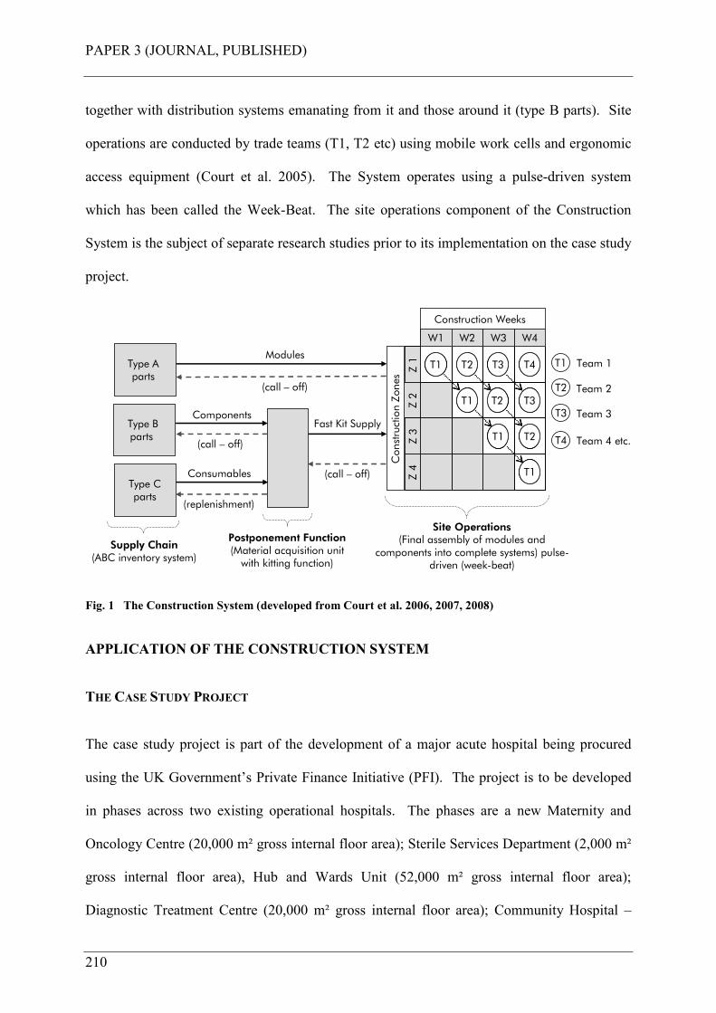
PAPER 3 (JOURNAL, PUBLISHED)
210
together with distribution systems emanating from it and those around it (type B parts). Site
operations are conducted by trade teams (T1, T2 etc) using mobile work cells and ergonomic
access equipment (Court et al. 2005). The System operates using a pulse-driven system
which has been called the Week-Beat. The site operations component of the Construction
System is the subject of separate research studies prior to its implementation on the case study
project.
Z 2
W1 W2 W3 W4
Z 1
Z 3
Z 4
T1 T2 T3 T4
T1 T2
T1 T2
T3
T1
Z 2
W1 W2 W3 W4
Z 1
Z 3
Z 4
T1 T2 T3 T4
T1 T2
T1 T2
T3
T1
W1 W2 W3 W4
Z 1
Z 3
Z 4
T1 T2 T3 T4
T1 T2
T1 T2
T3
T1
Construction Zones
Construction Weeks
Type A parts
Type B parts
Type Cparts
(call – off)
Postponement Function(Material acquisition unit with kitting function)
(replenishment)
Modules
Fast Kit Supply
(call – off)
Team 1
Team 2
Team 3
T1
Site Operations(Final assembly of modules and
components into complete systems) pulse-driven (week-beat)
Supply Chain(ABC inventory system)
Team 4 etc.
Components
Consumables
(call – off) T2
T3
T4
Fig. 1 The Construction System (developed from Court et al. 2006, 2007, 2008)
APPLICATION OF THE CONSTRUCTION SYSTEM
THE CASE STUDY PROJECT
The case study project is part of the development of a major acute hospital being procured
using the UK Government’s Private Finance Initiative (PFI). The project is to be developed
in phases across two existing operational hospitals. The phases are a new Maternity and
Oncology Centre (20,000 m² gross internal floor area); Sterile Services Department (2,000 m²
gross internal floor area), Hub and Wards Unit (52,000 m² gross internal floor area);
Diagnostic Treatment Centre (20,000 m² gross internal floor area); Community Hospital –

PAPER 3 (JOURNAL, PUBLISHED)
211
remote location (12,000 m² gross internal floor area). The project commenced construction in
December 2006 (M&E commenced August 2007) and is due for completion in 2012.
The Construction System is being applied on each phase of the case study project the first
being the new Maternity and Oncology Centre. This is a 20,000 m² building over four floors.
It has electrical and water storage plantrooms in its basement with main ventilation
plantrooms over the Oncology Centre at level two and on the roof at level five. Riser shafts
are located around the building and distribute air, water, medical gas, electricity and the like
throughout the building to the various departments. Corridor ceiling voids distribute the
services from the riser shafts and then further into individual rooms and spaces, again in the
ceiling voids. Finally, services distribute inside dry-lined walls to points of use such as
electrical sockets, sinks, basins and bed-head units; everything you would expect to see in a
new and modern healthcare facility.
Earlier work for this research project has described how the parts to be used that form the
complete M&E systems on the case study project were categorized using ABC parts
classification, with type A being modules, type B being loose components and type C being
consumables such as nuts, bolts, washers and the like. Described in this paper is the research
involved in setting the supply chain strategy. This is to pre-assemble as much as possible
offsite (type A parts) to be delivered Just-In-Time and incorporated into the final assembled
systems along with component kits (type B and C parts) in a series of small and simple tasks.
The labor strategy is also clear; to remove as much labor offsite as possible with those that
remain provided with good ergonomics, appropriate working tools and a good working
environment, thereby facilitating a quality of work.

PAPER 3 (JOURNAL, PUBLISHED)
212
THE PROCESS: SET BASED THINKING
The M&E elements for ABC classification were agreed upon according to principles and
ground rules pre-agreed by cross-functional teams. Liker (2004) called this set based
concurrent engineering. This term was used to describe how Toyota developed vehicle
designs using a cross-functional team of experts and the Project Leaders relied on that team.
This was the starting point for actually deciding upon what chunks of the M&E systems were
to be modularized (type A parts), and what would be parts kitted or replenished (type B and C
parts), as well as the selection of the actual components themselves. This activity was
conducted in a workshop environment, with project team members assigned to the team
because of their individual expertise. The team members were represented with the following
disciplines: Project Leader (one of the authors); Offsite Manufacturing Engineer;
Construction Manager; Commissioning Manager; Maintenance Engineer; Mechanical and
Electrical Engineer; Mechanical Design and Electrical Design Engineer; Architectural
Technician; Structural Engineer; Procurement Engineer and component suppliers. The initial
activity was to agree upon the guiding principles, design parameters and ground rules so that
decisions were made in the light of these and the team would not move forward unless each
had been satisfied. Three overarching principles were set and these are:
PRINCIPLE 1 INCIDENT AND INJURY FREE: People returning home safely every day after a
productive days work; minimize on-site labor; health, safety and quality shall be the over-
riding objectives of the design.
PRINCIPLE 2 DESIGN TO MAKE THE SITE ONE OF ASSEMBLY RATHER THAN
CONSTRUCTION: Engage in systematic analysis of the elements and their interconnection;
design for modular assembly; design for standardization; design solutions for re-use; engage
PAPER 3 (JOURNAL, PUBLISHED)
213
the internal and external supply chain to deploy expertise early in the design process – design
around a product.
PRINCIPLE 3 USE TECHNOLOGY ENABLERS: 3D/4D modelling (digital prototyping) is to be
deployed throughout the project; fully integrated and co-ordinated, 3D common data
structure; 3D intelligent objects provided by the internal & external supply chain (not the
subject of this paper).
The outputs of these workshops are described later in this paper. Together with the
workshops for parts analysis, construction sequencing was also agreed with a cross-functional
team. The team consisted of nominated members from the parts classification team, as well
as M&E, building, planning and specialist sub-contract trade personnel.
INSTALLATION SEQUENCING FOR CONSTRUCTION
A detailed analysis was undertaken of the installation sequencing, with particular emphasis on
ensuring that no two or more trades would work in the same place at the same time, unless
expressly designed to do so. The building is divided into construction zones; each being
approximately 1,000 m² (zones 1-17, plantrooms 1-3). This area of construction zone being
right-sized for each trade team to complete the planned work in a maximum five days. Here,
team T1 has one week to complete its work before moving to the next zone. The next team,
T2, follows on at the Week-Beat interval, and the next, T3, team follows similarly. Within
each construction zone mechanical and electrical work has various sub-process activities, as
do the building fabric works (dry-lining, ceilings, painting, flooring etc.). These tight and
dependant relationship are what Thomas et al. (2004) called symbiotic and these relationships
exist within this project. Table 1 shows the agreed sequences between each M&E process
(MEP1, 2, 3 etc.) and associated building fabric processes (BFP1, 2, 3 etc.).
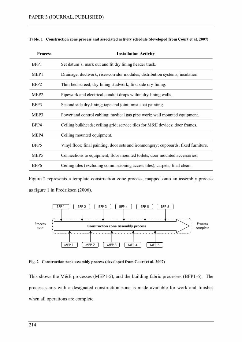
PAPER 3 (JOURNAL, PUBLISHED)
214
Table. 1 Construction zone process and associated activity schedule (developed from Court et al. 2007)
Process Installation Activity
BFP1 Set datum’s; mark out and fit dry lining header track.
MEP1 Drainage; ductwork; riser/corridor modules; distribution systems; insulation.
BFP2 Thin-bed screed; dry-lining studwork; first side dry-lining.
MEP2 Pipework and electrical conduit drops within dry-lining walls.
BFP3 Second side dry-lining; tape and joint; mist coat painting.
MEP3 Power and control cabling; medical gas pipe work; wall mounted equipment.
BFP4 Ceiling bulkheads; ceiling grid; service tiles for M&E devices; door frames.
MEP4 Ceiling mounted equipment.
BFP5 Vinyl floor; final painting; door sets and ironmongery; cupboards; fixed furniture.
MEP5 Connections to equipment; floor mounted toilets; door mounted accessories.
BFP6 Ceiling tiles (excluding commissioning access tiles); carpets; final clean.
Figure 2 represents a template construction zone process, mapped onto an assembly process
as figure 1 in Fredriksen (2006).
Processstart
Process complete
MEP 1
Construction zone assembly process
MEP 2 MEP 3 MEP 4 MEP 5
BFP 1 BFP 2 BFP 3 BFP 4 BFP 5 BFP 6
Fig. 2 Construction zone assembly process (developed from Court et al. 2007)
This shows the M&E processes (MEP1-5), and the building fabric processes (BFP1-6). The
process starts with a designated construction zone is made available for work and finishes
when all operations are complete.
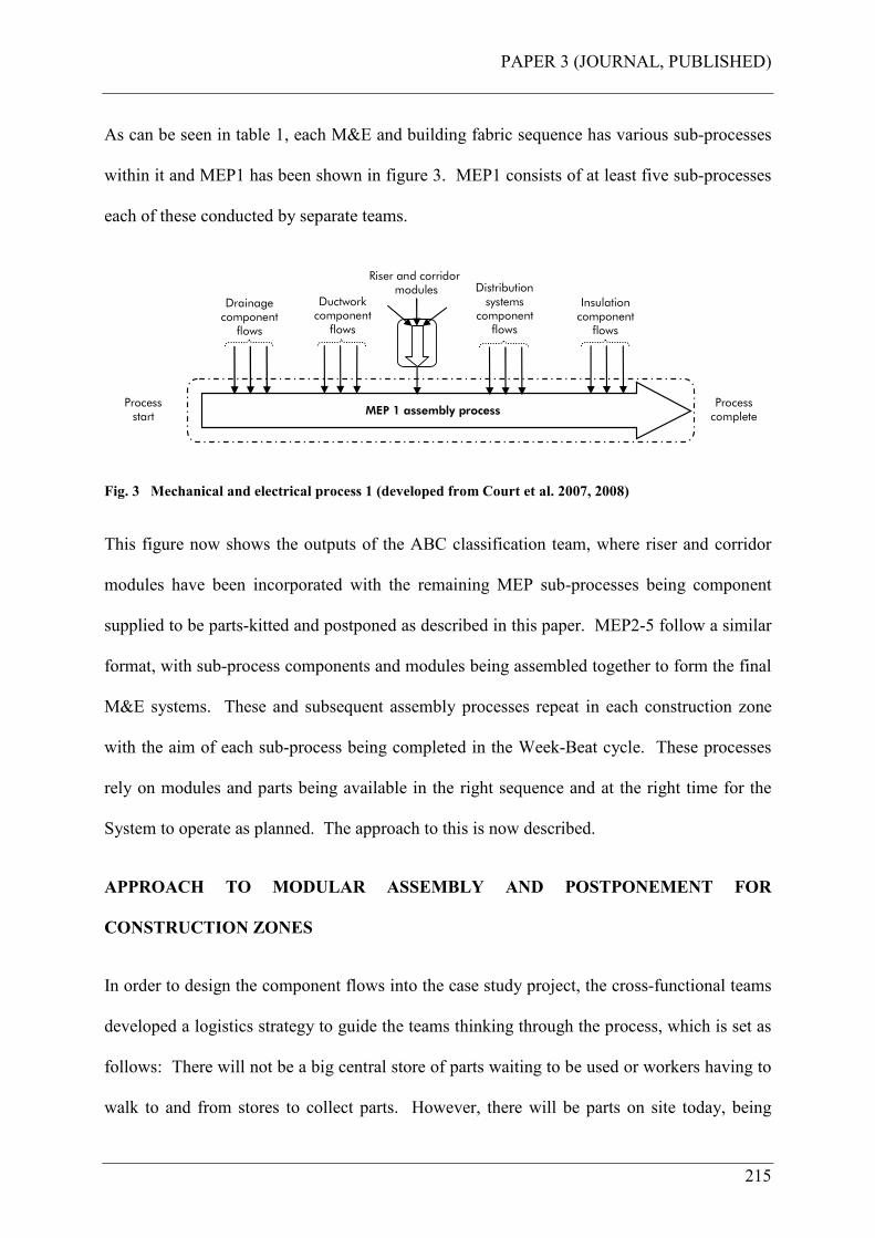
PAPER 3 (JOURNAL, PUBLISHED)
215
As can be seen in table 1, each M&E and building fabric sequence has various sub-processes
within it and MEP1 has been shown in figure 3. MEP1 consists of at least five sub-processes
each of these conducted by separate teams.
MEP 1 assembly process
Drainage componentflows
Ductworkcomponentflows
Insulationcomponentflows
Distribution systems componentflows
Riser and corridormodules
Processstart
Process complete
Fig. 3 Mechanical and electrical process 1 (developed from Court et al. 2007, 2008)
This figure now shows the outputs of the ABC classification team, where riser and corridor
modules have been incorporated with the remaining MEP sub-processes being component
supplied to be parts-kitted and postponed as described in this paper. MEP2-5 follow a similar
format, with sub-process components and modules being assembled together to form the final
M&E systems. These and subsequent assembly processes repeat in each construction zone
with the aim of each sub-process being completed in the Week-Beat cycle. These processes
rely on modules and parts being available in the right sequence and at the right time for the
System to operate as planned. The approach to this is now described.
APPROACH TO MODULAR ASSEMBLY AND POSTPONEMENT FOR
CONSTRUCTION ZONES
In order to design the component flows into the case study project, the cross-functional teams
developed a logistics strategy to guide the teams thinking through the process, which is set as
follows: There will not be a big central store of parts waiting to be used or workers having to
walk to and from stores to collect parts. However, there will be parts on site today, being
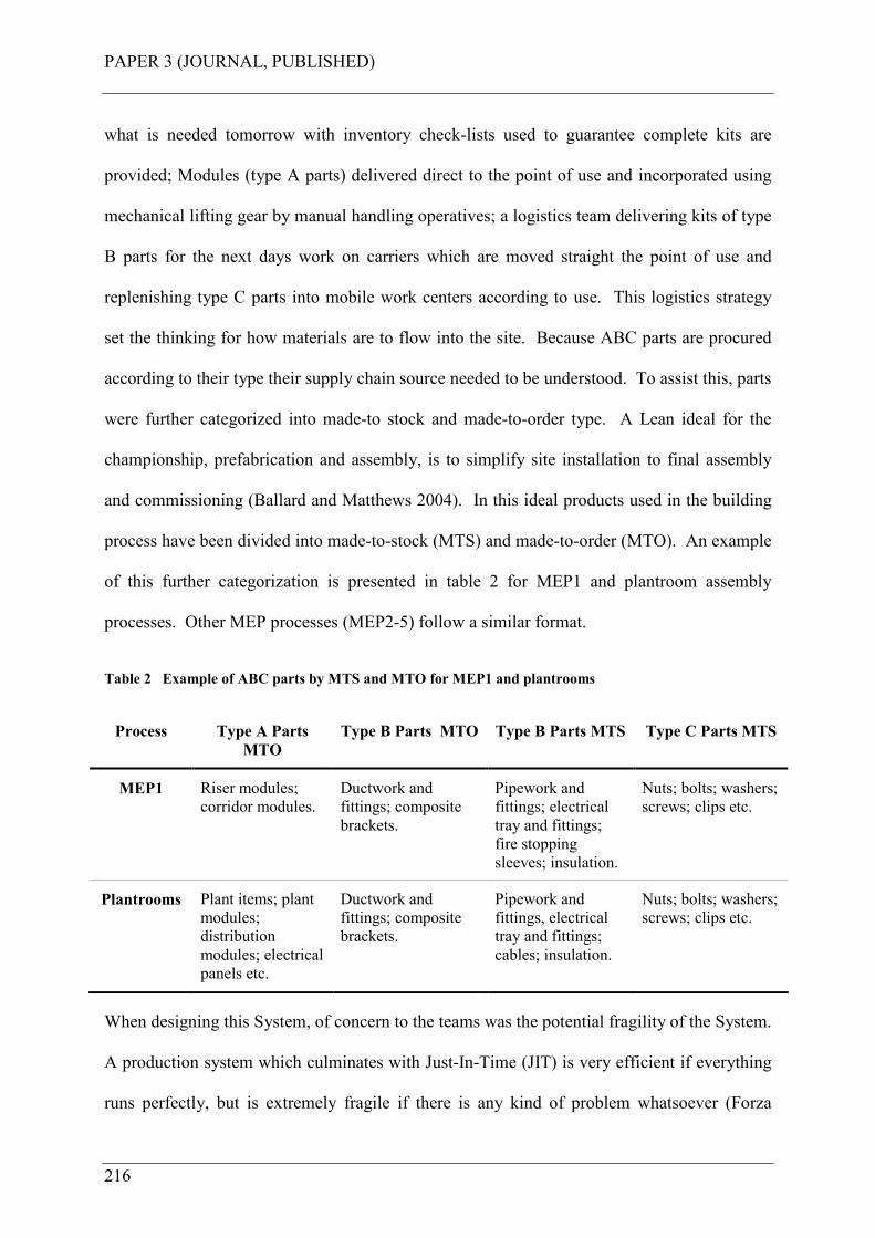
PAPER 3 (JOURNAL, PUBLISHED)
216
what is needed tomorrow with inventory check-lists used to guarantee complete kits are
provided; Modules (type A parts) delivered direct to the point of use and incorporated using
mechanical lifting gear by manual handling operatives; a logistics team delivering kits of type
B parts for the next days work on carriers which are moved straight the point of use and
replenishing type C parts into mobile work centers according to use. This logistics strategy
set the thinking for how materials are to flow into the site. Because ABC parts are procured
according to their type their supply chain source needed to be understood. To assist this, parts
were further categorized into made-to stock and made-to-order type. A Lean ideal for the
championship, prefabrication and assembly, is to simplify site installation to final assembly
and commissioning (Ballard and Matthews 2004). In this ideal products used in the building
process have been divided into made-to-stock (MTS) and made-to-order (MTO). An example
of this further categorization is presented in table 2 for MEP1 and plantroom assembly
processes. Other MEP processes (MEP2-5) follow a similar format.
Table 2 Example of ABC parts by MTS and MTO for MEP1 and plantrooms
Process Type A Parts
MTO
Type B Parts MTO Type B Parts MTS Type C Parts MTS
MEP1 Riser modules;
corridor modules.
Ductwork and
fittings; composite
brackets.
Pipework and
fittings; electrical
tray and fittings;
fire stopping
sleeves; insulation.
Nuts; bolts; washers;
screws; clips etc.
Plantrooms Plant items; plant
modules;
distribution
modules; electrical
panels etc.
Ductwork and
fittings; composite
brackets.
Pipework and
fittings, electrical
tray and fittings;
cables; insulation.
Nuts; bolts; washers;
screws; clips etc.
When designing this System, of concern to the teams was the potential fragility of the System.
A production system which culminates with Just-In-Time (JIT) is very efficient if everything
runs perfectly, but is extremely fragile if there is any kind of problem whatsoever (Forza
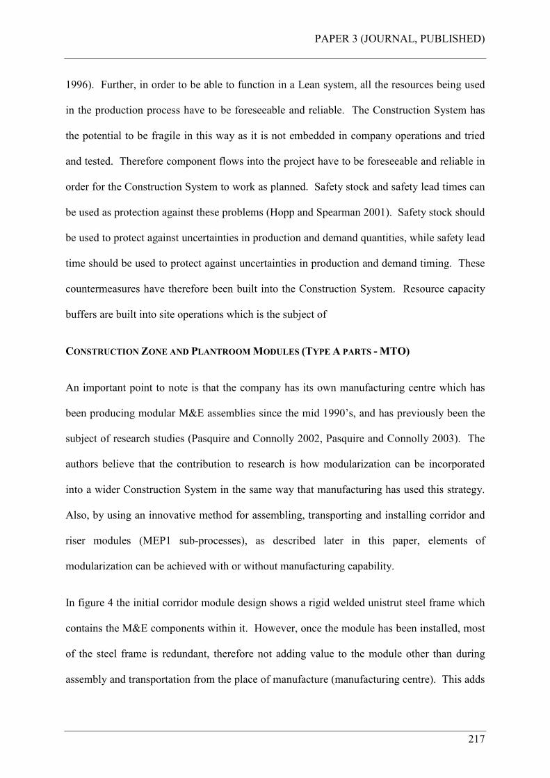
PAPER 3 (JOURNAL, PUBLISHED)
217
1996). Further, in order to be able to function in a Lean system, all the resources being used
in the production process have to be foreseeable and reliable. The Construction System has
the potential to be fragile in this way as it is not embedded in company operations and tried
and tested. Therefore component flows into the project have to be foreseeable and reliable in
order for the Construction System to work as planned. Safety stock and safety lead times can
be used as protection against these problems (Hopp and Spearman 2001). Safety stock should
be used to protect against uncertainties in production and demand quantities, while safety lead
time should be used to protect against uncertainties in production and demand timing. These
countermeasures have therefore been built into the Construction System. Resource capacity
buffers are built into site operations which is the subject of
CONSTRUCTION ZONE AND PLANTROOM MODULES (TYPE A PARTS - MTO)
An important point to note is that the company has its own manufacturing centre which has
been producing modular M&E assemblies since the mid 1990’s, and has previously been the
subject of research studies (Pasquire and Connolly 2002, Pasquire and Connolly 2003). The
authors believe that the contribution to research is how modularization can be incorporated
into a wider Construction System in the same way that manufacturing has used this strategy.
Also, by using an innovative method for assembling, transporting and installing corridor and
riser modules (MEP1 sub-processes), as described later in this paper, elements of
modularization can be achieved with or without manufacturing capability.
In figure 4 the initial corridor module design shows a rigid welded unistrut steel frame which
contains the M&E components within it. However, once the module has been installed, most
of the steel frame is redundant, therefore not adding value to the module other than during
assembly and transportation from the place of manufacture (manufacturing centre). This adds
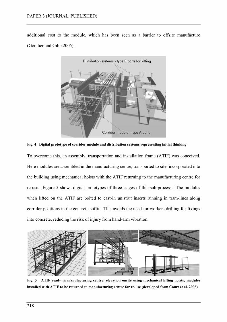
PAPER 3 (JOURNAL, PUBLISHED)
218
additional cost to the module, which has been seen as a barrier to offsite manufacture
(Goodier and Gibb 2005).
Corridor module - type A parts
Distribution systems - type B parts for kitting
Fig. 4 Digital prototype of corridor module and distribution systems representing initial thinking
To overcome this, an assembly, transportation and installation frame (ATIF) was conceived.
Here modules are assembled in the manufacturing centre, transported to site, incorporated into
the building using mechanical hoists with the ATIF returning to the manufacturing centre for
re-use. Figure 5 shows digital prototypes of three stages of this sub-process. The modules
when lifted on the ATIF are bolted to cast-in unistrut inserts running in tram-lines along
corridor positions in the concrete soffit. This avoids the need for workers drilling for fixings
into concrete, reducing the risk of injury from hand-arm vibration.
Fig. 5 ATIF ready in manufacturing centre; elevation onsite using mechanical lifting hoists; modules
installed with ATIF to be returned to manufacturing centre for re-use (developed from Court et al. 2008)
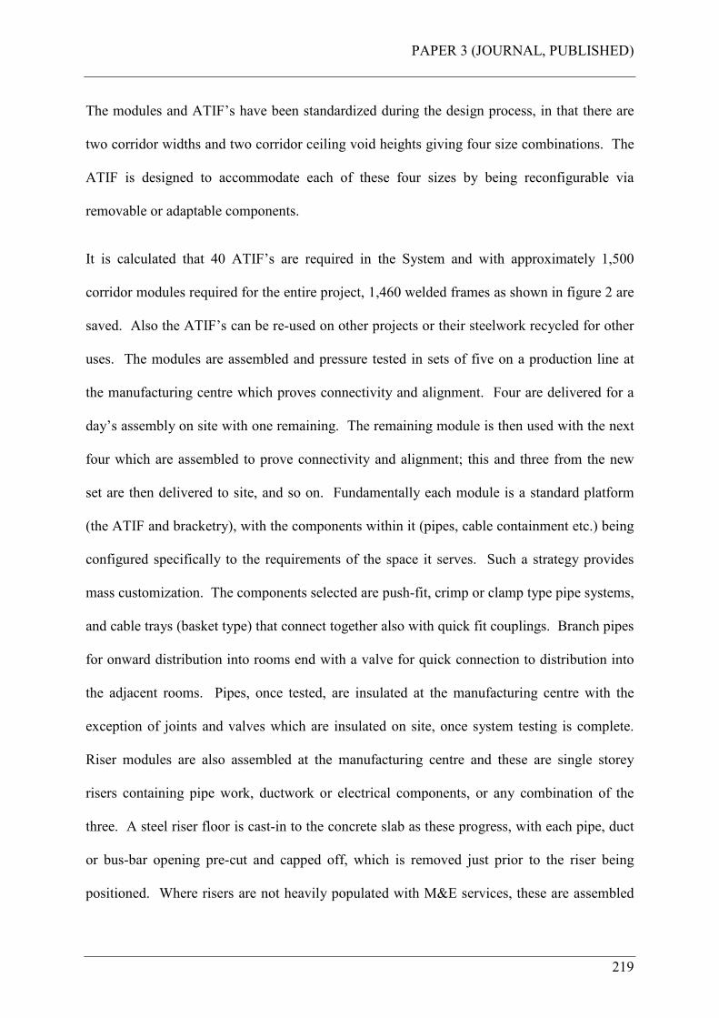
PAPER 3 (JOURNAL, PUBLISHED)
219
The modules and ATIF’s have been standardized during the design process, in that there are
two corridor widths and two corridor ceiling void heights giving four size combinations. The
ATIF is designed to accommodate each of these four sizes by being reconfigurable via
removable or adaptable components.
It is calculated that 40 ATIF’s are required in the System and with approximately 1,500
corridor modules required for the entire project, 1,460 welded frames as shown in figure 2 are
saved. Also the ATIF’s can be re-used on other projects or their steelwork recycled for other
uses. The modules are assembled and pressure tested in sets of five on a production line at
the manufacturing centre which proves connectivity and alignment. Four are delivered for a
day’s assembly on site with one remaining. The remaining module is then used with the next
four which are assembled to prove connectivity and alignment; this and three from the new
set are then delivered to site, and so on. Fundamentally each module is a standard platform
(the ATIF and bracketry), with the components within it (pipes, cable containment etc.) being
configured specifically to the requirements of the space it serves. Such a strategy provides
mass customization. The components selected are push-fit, crimp or clamp type pipe systems,
and cable trays (basket type) that connect together also with quick fit couplings. Branch pipes
for onward distribution into rooms end with a valve for quick connection to distribution into
the adjacent rooms. Pipes, once tested, are insulated at the manufacturing centre with the
exception of joints and valves which are insulated on site, once system testing is complete.
Riser modules are also assembled at the manufacturing centre and these are single storey
risers containing pipe work, ductwork or electrical components, or any combination of the
three. A steel riser floor is cast-in to the concrete slab as these progress, with each pipe, duct
or bus-bar opening pre-cut and capped off, which is removed just prior to the riser being
positioned. Where risers are not heavily populated with M&E services, these are assembled
PAPER 3 (JOURNAL, PUBLISHED)
220
onsite using pre-assemblies and kits of associated parts. Plantroom components such as pump
sets, pressurization units, valve stations etc. are grouped together and assembled offsite into
plantroom modules by the company. These are also wired and insulated at the manufacturing
centre to further reduce the amount of work on site. Interconnections between plant modules
and risers are site assembled also using pre-assemblies and kits of associated parts.
CONSTRUCTION ZONE COMPONENT FLOWS (TYPE B AND C PARTS – MTO AND MTS)
The approach to manage the flow of components to the point of use has been described earlier
in this paper, which is to kit the specific parts for the MEP operation and postpone its delivery
until it is needed. The kitting itself is carried out using MTO and MTS suppliers as re-
packing centers and de-coupling points. Bertelsen et al. (2006) describe previous experiments
using this approach. Each of the components is selected to be quick-fit, commercially
available and tried and tested technology. Small pipe work for water and drainage is either
push-fit, crimp-fit or clamp type. Larger pipes are welded and flanged, but made offsite.
Electrical trays are basket, trunking or ladder type which fit together quickly with snap-on
couplings. Power cables for small power and lighting is a modular plug-and-play connectable
system configured on site from standard MTO components. Larger armoured cables for main
power supplies are standard type MTS and delivered on large cable drums. Low voltage
cables (data, BMS, nurse call etc.) are also standard items on small drums or boxed as
appropriate. Where components can be assembled together operatives and tools are provided
at the local supplier’s branch to pre-form conduits and assemble pipe clips onto brackets and
the like. Each of these components are delivered to site in purpose made roll cages or similar,
with kits offloaded from the point of delivery and delivered to the point of use by a logistics
team trained in manual handling methods, thereby avoiding the need for installation team
members to do this.
PAPER 3 (JOURNAL, PUBLISHED)
221
LABOR AND ASSOCIATED COST FORECAST
Combining offsite modular assembly and postponement with the Lean site operations
component of the Construction System and projecting the labor required to perform the
planned operations forecasts a 35% reduction of onsite labor. This forecast is derived from a
comparison of calculated estimates of labor times between conducting the work using
traditional methods and by using the Construction System as described in this paper. For all
MEP processes, including plantrooms, the traditional method is estimated at 202,800 hours,
with the construction method estimated at 131,84051 hours. This equates to a difference of
70,96052 hours between the two methods; a 35% reduction. Also, because of the
simplification of the assembly process, a lower ratio of skilled to semi-skilled operatives is
required, which reduces the average hourly cost of labor. This will further reduce the outturn
labor cost of the project. A reduction in total cycle-time is also achieved using the System
however, at this stage of research this is kept as a time buffer between M&E construction and
commissioning. The reduction in forecasted labor does not represent an overall forecasted
labor saving, as work has shifted offsite for modular assembly; it represents a reduction in
labor onsite.
The sub-process within MEP1, corridor modules (ATIF’s) has been evaluated (once the work
was complete) and reported in Court et al. (2008). Here 1,568 actual onsite hours were
required elevating and connecting together a total of 196 modules, compared to 22,320 hours
estimated using traditional methods with various trade teams completing the required work all
working at height; a 93% reduction. An 8.62% cost benefit is also reported. This cost
51 Corrected from published paper as printed. This is printed as 131,040 hours and should read 131,840
hours (authors tying error).
52 Corrected from published paper as printed. This is printed as 71,760 hours and should read 70,960
hours (authors tying error).

PAPER 3 (JOURNAL, PUBLISHED)
222
analysis compares an estimate of traditional method against actual offsite method including:
basic materials; material waste; labor including supervision and testing; productivity losses;
transport costs; site equipment; rectification and rework costs and design costs. Productivity
losses means a cost factor estimate of the productivity losses possible between the different
methods, including weather, stoppages, damage, theft and interferences etc. The estimated
cost of this has been assessed as 25% of traditional installation labor only to demonstrate this
variable. As the paper reports, the value of this variable provide the cost benefit assessed
between the different methods. In other words, if estimated productivity losses for the
traditional method were zero percent, then there would be no cost benefit of the offsite
method; but this is unlikely in the opinion of the authors and according to previous research
(Hawkins 1997). This measured average overall productivity as 37% on the UK projects
monitored. In essence, the increased offsite costs for manufacturing centre overhead,
additional transport and assembly drawings are more than offset by the higher onsite costs
related to productivity, supervision, site testing and rework. When this benefit has been
combined with the results emerging from the implementation of the Construction System
through all MEP processes, a final analysis against overall forecasted benefits will be made
and reported in future research papers.
CONCLUSION
This paper has presented the outcome of an engineering study (and certain results) as part of
the design and development of a Lean and agile Construction System and in particular its
supply chain component combining modular assembly with a postponement function for a
designated building phase within a case study project. The Construction System component
described in this paper has been developed as a specific set of countermeasures to overcome
what would otherwise occur had these interventions not been made. Modular assembly using
PAPER 3 (JOURNAL, PUBLISHED)
223
mechanical lifting aids will significantly reduce the risk of manual handling injury to workers.
It will need fewer operatives to carry out the simpler assembly tasks required and risk of
injury is reduced by having fewer workers operating at height. It is also a method to avoid
symbiotic relationships that would otherwise exist which will increase the performance of
crews carrying out their operations. Congestion on site will be reduced which itself will
eliminate the generation of hazards and increase the output of workers. Productivity will be
improved because less work is required on site by workers cutting, drilling, assembly and
elevating parts into position using traditional methods. Furthermore, a significant gain in
installation performance will be achieved as the System has adopted innovative quick-fit
components and systems. Postponing kits of parts offsite until the time they are needed will
avoid the poor site storage and handling strategies that BSRIA report which have shown to be
the cause of delays and lost productivity in UK M&E construction. By managing the flows of
components in this way will enable trades to perform their operations as planned avoiding
potential trade stacking and out of sequence working that has been seen to occur. This
research has forecast that a reduction of 35% of onsite labor can be achieved and a lower skill
mix is required to perform the simpler assembly tasks as a result. A further benefit of this is
that the company avoids the potential risk they face due to the shortage of trained workers
available in UK construction, with the lower skill mix resulting in a reduced average labor
cost on the project. Whilst certain elements of what has been described in this paper are
common practice in the UK M&E industry, the authors believe that the contribution to
research is the combination of countermeasures described that have been incorporated into a
wider Construction System, in the same way that manufacturing has used this strategy. Also
by developing an innovative method for assembling, transporting and installing corridor and
riser modules, using an ATIF, modularization can be achieved with or without offsite
manufacturing capability. In fact, this approach can be adopted by M&E contractors on site,
PAPER 3 (JOURNAL, PUBLISHED)
224
but off-line. Space permitting, a small assembly workshop can be set up adjacent to a
construction site to carry out this process, or supply chain partners can be developed and
encouraged to use this method. Also, parts-kitting can be achieved by the supply chain
according to the principles set out in this paper. If distances for transportation are too great,
then again this function could be carried out on a construction site, but not at the point of use,
as is traditionally seen. This should be done off-line by a logistics team, and not by the
workers themselves. This Construction System component presents a set of countermeasures
that are designed to overcome what traditionally occurs on UK construction sites as this
research paper has described and to meet the stated research project objectives; which is to
design a way of working on site for improved health, safety and productivity for the company.
FURTHER RESEARCH
The next phase of research will be to test the Construction System and measure the results
emerging from the implementation on a case study project. This will be for the M&E work
associated with the Maternity and Oncology Centre, a phase within the case study project.
This implementation phase will test the System by measuring the expected benefits which is
to avoid the risk of incidents or injury to workers, have less workers onsite carrying out
simpler assembly tasks, and with improved productivity to maintain the labor cost centre
budget thereby defending the company’s margin on the project (Court et al. 2005).
REFERENCES
Ballard, G. and Matthews, O. (2004). Championship – prefabrication and assembly. Proc.,
Twelfth Annual Conf. of the Int. Group for Lean Construction (IGLC-12), Elsinore,
Denmark, 625-628.
PAPER 3 (JOURNAL, PUBLISHED)
225
Bertelsen, S., Koskela, L., Henrich, G., and Rooke, J. (2006). Critical flow-towards a
construction flow theory. Proc., Fourteenth Annual Conf. of the Int. Group for Lean
Construction (IGLC-14), Santiago, Chile, 31-40.
Burbidge, J.L. (1996). Period batch control, Oxford University Press, New York, USA.
Court, P., Pasquire, C., Gibb, A.G.F., and Bower, D. (2005). Lean as an antidote to labour
cost escalation on complex mechanical and electrical projects.” Proc., Thirteenth
Annual Conf. of the Int. Group for Lean Construction (IGLC-13), Sydney, Australia, 3-
11.
Court, P., Pasquire, C., Gibb, A.G.F., and Bower, D. (2006). Design of a Lean and agile
Construction System for a large and complex mechanical and electrical project. Proc.,
Fourteenth Annual Conf. of the Int. Group for Lean Construction (IGLC-14), Santiago,
Chile, 151-164.
Court, P., Pasquire, C., Gibb, A.G.F., and Bower, D. (2007). Transforming traditional
construction into a modern process of assembly using Construction Physics. Proc.,
Fifteenth Annual Conf. of the Int. Group for Lean Construction (IGLC-15), Lansing,
USA, 345-356.
Court, P., Pasquire, C., Gibb, A.G.F., and Bower, D. (2008). Modular assembly in healthcare
construction – a mechanical and electrical case study. Proc., Sixteenth Annual Conf. of
the Int. Group for Lean Construction (IGLC-16), Manchester, United Kingdom, 521-
531.
PAPER 3 (JOURNAL, PUBLISHED)
226
Fredriksson, P. (2006). Mechanisms and rationales for the coordination of a modular
assembly system – the case of Volvo cars. Int. J. of Ops. and Prod. Manage., Vol 26
No. 4, 350-370.
Forza, C. (1996). Work organisation in Lean production and traditional plants – what are the
differences? Int. J. of Ops. Manage., Vol. 16. No. 2, 1996, 42-62.
Gibb, A.G.F. (2006) (Keynote). Occupational health: slow accidents need solutions fast, in
Fang, Choudry & Hinze (eds), Global Unity for Safety & Health in Construction, Proc.,
of CIBW99 Int. Conf., June 2006, Beijing, Tsinghua University Press, 22-33.
Goodier, C.I., Gibb, A.G.F. (2005). Barriers and opportunities for offsite in the UK.
Systematic Innovation in the Management of Projects and Processes. Abdul Samad
Kazi (ed), cib Helsinki international joint symposium, 148-158.
Granath, J.A. (1998). Torlanda to Uddevalla via Kalmar: a journey in production practice in
Volvo. Seminário Internacional Reestruturaçã Productiva, Flexibilidade do Trabalho e
Novas Competências Profissionais, COPPE/UFRJ, Rio de Janeiro, Brasil.
Hawkins, G. (1997). Improving M&E site productivity. BSRIA technical note TN 14/97,
The Building Services Research and Information Association, Bracknell, UK.
Hawkins, G. (2002). Site Productivity – 2002. A guide to the uptake of improvements.
BSRIA technical note TN 13/2002, The Building Services Research and Information
Association, Bracknell, UK.
Health and Safety Executive (2000). Backs for the future: safe manual handling in
construction. HSE books, Norwich, UK.
PAPER 3 (JOURNAL, PUBLISHED)
227
Health and Safety Executive (2007). Health and safety in the construction industry.
<http://www.hse.gov.uk/construction/index.htm> (Mar. 4, 2007).
Health and Safety Executive (2007a). Better backs in construction.
<http://www.hse.gov.uk/construction/backs/index.htm> (Mar. 4, 2007).
Health and Safety Executive (2007b). Musculoskeletal disorders – HSE and MSD’s.
<http://www.hse.gov.uk/msd/hsemsd.htm> (Mar. 4, 2007).
Hopp, W. J., and Spearman, M. L. (2001). The MRP crusade. Factory physics, 2nd Ed.,
Irwin/McGraw-Hill, New York, USA, 109-150.
Horman, M. J., Orosz, M. P., and Riley, D. R. (2006). Sequence planning for electrical
construction. J. Constr. Eng. Manage., 132(4), 363-372.
Liker, J. K. (2004). The Toyota Way: 14 management principles from the world’s greatest
manufacturer, McGraw-Hill, New York, USA.
Pasquire, C.L., and Connolly, G.E. (2002). Leaner construction through off-site
manufacturing. Proc., Tenth Annual Conf. of the Int. Group for Lean Construction
(IGLC-10), Gramado, Brazil, 263-275.
Pasquire, C.L., and Connolly, G.E. (2003). Design for manufacture and assembly. Proc.,
Eleventh Annual Conf. of the International Group for Lean Construction (IGLC-11),
Blacksburg, Virginia, 184-194.
Skipworth, H., and Harrison, A. (2004). Implications of form postponement to
manufacturing: a case study. Int. J. Prod. res., 15 May 2004, vol. 42, no. 10, 2063-
2081.

PAPER 3 (JOURNAL, PUBLISHED)
228
Thomas, H. R., Horman, M. J., and de Souza, U. E. L. (2004). Symbiotic crew relationships
and labor flow. J. Constr. Eng. Manage., 130(6), 908-917.
Ulrich, K. T., Eppinger, S. D. (2004). Product architecture. Product design and development,
3rd Ed., McGraw Hill, New York, USA, 163-186.
Wilson, D. (2000). Innovative M&E installation. BSRIA ACT 9/2000, the Building Services
Research and Information Association, Bracknell, UK.
Winch, G. M., and North, S. (2006). Critical space analysis. J. Constr. Eng. Manage., 132(5),
473-481.
Yang, B., and Burns, N. (2003). Implications of postponement for the supply chain. Int. J.
Prod. res., 2003, vol. 41, no. 9, 2075-2090.
PAPER 4 (REFEREED, CONFERENCE)
229
APPENDIX D PAPER 4 (REFEREED, CONFERENCE)
Court, P., Pasquire, C., Gibb, A.G.F., (2008). Modular assembly in healthcare construction –
a mechanical and electrical case study. Proc., Sixteenth Annual Conf. of the Int. Group for
Lean Construction (IGLC-16), Manchester, United Kingdom, 521-531.

PAPER 4 (REFEREED, CONFERENCE)
230

PAPER 4 (REFEREED, CONFERENCE)
231
MODULAR ASSEMBLY IN HEALTHCARE CONSTRUCTION
– A MECHANICAL AND ELECTRICAL CASE STUDY
Peter Court, Dr. Christine Pasquire, Prof. Alistair Gibb
ABSTRACT
This paper presents findings as part of a research project to develop and implement a Lean
and agile Construction System on a case study project. The objective of the research project
for the sponsor company is to improve its projects site operations, making them safer for the
worker, and improving efficiency and productivity. A principle output of the research is the
development and use of an innovative method for assembling offsite, transporting and
installing mechanical and electrical distribution modules. In total 196 modules were installed
in 17 construction zones on the case study project and the results show that zero accidents
occurred either onsite or offsite associated with this work; an 8.62% cost saving is achieved
over an estimation of traditional methods (with an estimated productivity loss of 25% for
traditional method site labour); a higher quality is achieved with less site rework; 93% less
hours are required onsite for the S&P method (much fewer operatives onsite at risk of injury);
and a shorter overall cycle-time is required to complete the work when compared to
traditional methods.
This paper reports on the findings using IMMPREST software as a tool for assessing the
benefits derived from the use of modular offsite assembly for this case study.
KEY WORDS
Construction System, IMMPREST, health, safety, productivity.
PAPER 4 (REFEREED, CONFERENCE)
232
INTRODUCTION
This is a practical paper drawn from a collaborative research project (the research project)
being undertaken at the Centre for Innovative Collaborative Engineering at Loughborough
University, UK. The programme is funded by the Engineering and Physical Sciences
Research Council (EPSRC) and is sponsored by a major UK mechanical and electrical
contractor (the company). The research project has specific objectives, which will be capable
of making a significant contribution to the performance of the sponsor company.
The company is developing a Construction System in order to improve the performance of its
projects, and earlier research in this field (Court et al. 2005) has shown that Lean
interventions when applied to a case study project had positive results. The next phase of the
research (Court et al. 2006, 2007), using leading edge research and learning, designed a Lean
and agile Construction System which is to be implemented on a major private finance
initiative (PFI) hospital development, and in particular the mechanical and electrical (M&E)
elements within it (the case study project). This paper reports on the findings from the
implementation of a component of the Construction System, the offsite modular assembly of
corridor mechanical and electrical distribution services using assembly, transportation and
installation frames (ATIF’s), described in Court et al. 2007. This case study uses using the
IMMPREST53 toolkit which Pasquire et al. (2005) describe as a tool for assessing the benefits
derived from the use of modular offsite assembly against what would have been traditional
installation methods. The benefits are classified into six categories and these are cost; time;
quality; health and safety; sustainability and site benefits.
53 Interactive Model for Measuring Preassembly and Standardisation in construction.

PAPER 4 (REFEREED, CONFERENCE)
233
RESEARCH PROJECT OBJECTIVES
The objective of this project for the company is to improve site operations, making them safer
for the worker and to improve productivity as a countermeasure to the prevailing conditions in
UK construction and the company itself. Safety is at the core of the company and according
to the Business Leaders “…it is an absolute right for people to return home safely at the end
of a productive day’s work,” and “failure to do so renders the company valueless.” The key
words here being safely and productive, these are therefore the key objectives of this research
project, which is to design and implement a way of working on site, the countermeasures, that
will satisfy these objectives.
THE CONSTRUCTION SYSTEM
The Construction System is the methodology to deliver the objectives of the sponsor company
and is represented in figure 1. Its underpinning theory incorporates manufacturing concepts
such as modular assembly, postponement, reflective manufacture, pulse-driven scheduling
and ABC parts classification (Court et al. 2006). The System is designed with Lean and agile
concepts to specifically eliminate waste from M&E (and key interfacing trades) construction
activities (the Lean dimension). The agile dimension is designed to provide each trade team
exactly what they want, when they want it and where they want it. These Lean and agile
attributes are designed to standardise the work, process and products to create flow, pull and
value delivery. The ergonomic and workplace organisation attributes are designed to
specifically improve workers health, safety and productive output (Court et al. 2005). Its key
components are its supply chain with a postponement function and its site operations. The
supply chain component has been categorised using ABC parts classification with modules
(type A) being delivered directly to site on a call-off system. Components and consumables
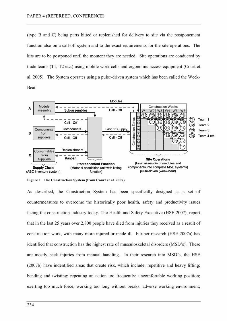
PAPER 4 (REFEREED, CONFERENCE)
234
(type B and C) being parts kitted or replenished for delivery to site via the postponement
function also on a call-off system and to the exact requirements for the site operations. The
kits are to be postponed until the moment they are needed. Site operations are conducted by
trade teams (T1, T2 etc.) using mobile work cells and ergonomic access equipment (Court et
al. 2005). The System operates using a pulse-driven system which has been called the Week-
Beat.
W1 W2 W3 W4 W5 W6
Z 1
Z 2
Z 3
Z 4
Z 5
Z 6
T1 T2 T3 T4
T1 T2
T1 T2
T3
T1
T1
T1
T2
T2
T3
T3
T4
T4
Construction Zones
Construction WeeksModule
assembly
Components
from
suppliers
Consumables
from
suppliers
A
B
C
Components
Kanban
Call - Off
Postponement Function
(Material acquisition unit with kitting
function)
Replenishment
Call - Off
Fast Kit Supply
Call - Off
Modules
T5
T5
T6
T3
T4
Team 1
Team 2
Team 3
Team 4 etc
T1
T2
Site Operations
(Final assembly of modules and
components into complete M&E systems)
pulse-driven (week-beat) Supply Chain
(ABC inventory system)
Sub-assemblies
Call - Off
Figure 1 The Construction System (from Court et al. 2007)
As described, the Construction System has been specifically designed as a set of
countermeasures to overcome the historically poor health, safety and productivity issues
facing the construction industry today. The Health and Safety Executive (HSE 2007), report
that in the last 25 years over 2,800 people have died from injuries they received as a result of
construction work, with many more injured or made ill. Further research (HSE 2007a) has
identified that construction has the highest rate of musculoskeletal disorders (MSD’s). These
are mostly back injuries from manual handling. In their research into MSD’s, the HSE
(2007b) have indentified areas that create risk, which include; repetitive and heavy lifting;
bending and twisting; repeating an action too frequently; uncomfortable working position;
exerting too much force; working too long without breaks; adverse working environment;
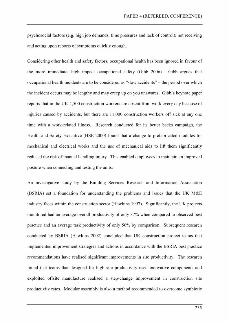
PAPER 4 (REFEREED, CONFERENCE)
235
psychosocial factors (e.g. high job demands, time pressures and lack of control); not receiving
and acting upon reports of symptoms quickly enough.
Considering other health and safety factors, occupational health has been ignored in favour of
the more immediate, high impact occupational safety (Gibb 2006). Gibb argues that
occupational health incidents are to be considered as “slow accidents” – the period over which
the incident occurs may be lengthy and may creep up on you unawares. Gibb’s keynote paper
reports that in the UK 4,500 construction workers are absent from work every day because of
injuries caused by accidents, but there are 11,000 construction workers off sick at any one
time with a work-related illness. Research conducted for its better backs campaign, the
Health and Safety Executive (HSE 2000) found that a change to prefabricated modules for
mechanical and electrical works and the use of mechanical aids to lift them significantly
reduced the risk of manual handling injury. This enabled employees to maintain an improved
posture when connecting and testing the units.
An investigative study by the Building Services Research and Information Association
(BSRIA) set a foundation for understanding the problems and issues that the UK M&E
industry faces within the construction sector (Hawkins 1997). Significantly, the UK projects
monitored had an average overall productivity of only 37% when compared to observed best
practice and an average task productivity of only 56% by comparison. Subsequent research
conducted by BSRIA (Hawkins 2002) concluded that UK construction project teams that
implemented improvement strategies and actions in accordance with the BSRIA best practice
recommendations have realised significant improvements in site productivity. The research
found that teams that designed for high site productivity used innovative components and
exploited offsite manufacture realised a step-change improvement in construction site
productivity rates. Modular assembly is also a method recommended to overcome symbiotic
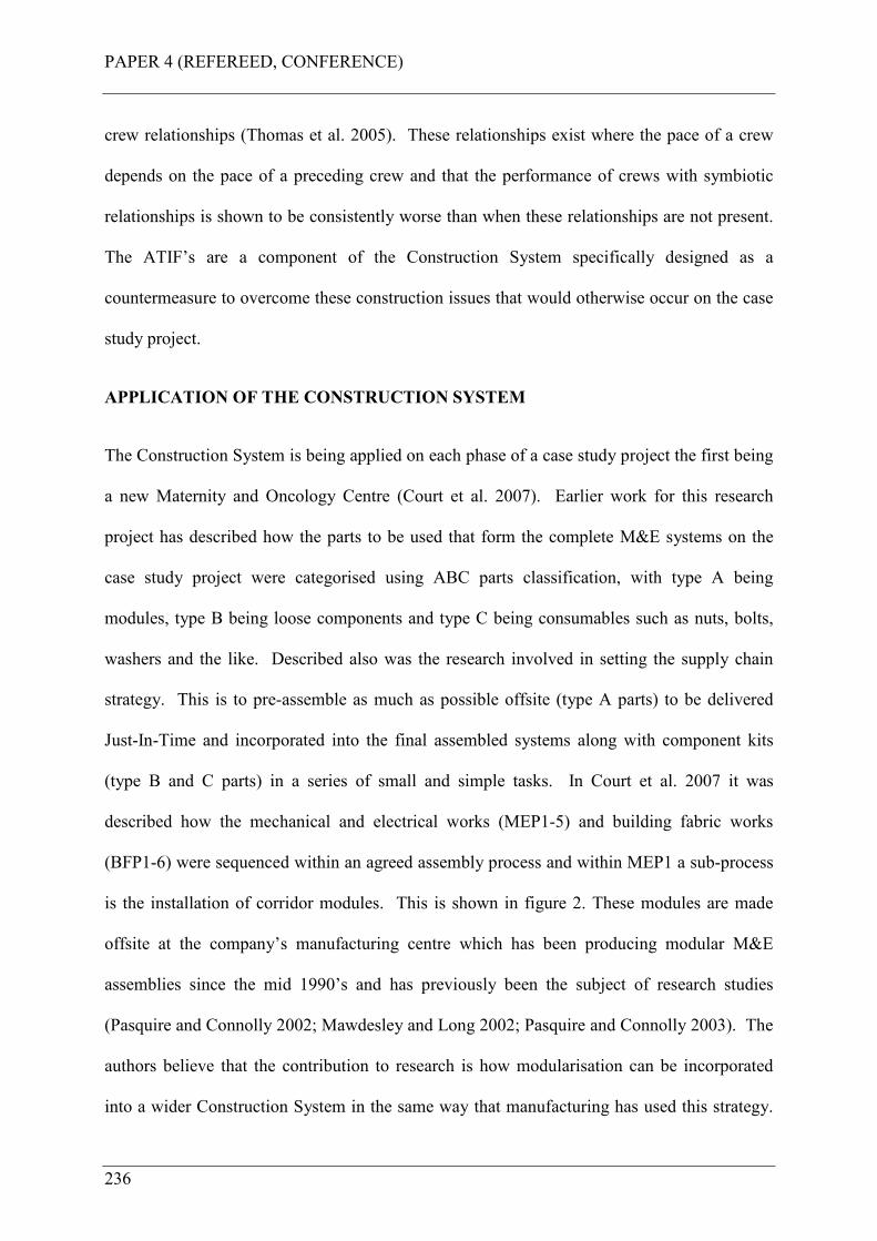
PAPER 4 (REFEREED, CONFERENCE)
236
crew relationships (Thomas et al. 2005). These relationships exist where the pace of a crew
depends on the pace of a preceding crew and that the performance of crews with symbiotic
relationships is shown to be consistently worse than when these relationships are not present.
The ATIF’s are a component of the Construction System specifically designed as a
countermeasure to overcome these construction issues that would otherwise occur on the case
study project.
APPLICATION OF THE CONSTRUCTION SYSTEM
The Construction System is being applied on each phase of a case study project the first being
a new Maternity and Oncology Centre (Court et al. 2007). Earlier work for this research
project has described how the parts to be used that form the complete M&E systems on the
case study project were categorised using ABC parts classification, with type A being
modules, type B being loose components and type C being consumables such as nuts, bolts,
washers and the like. Described also was the research involved in setting the supply chain
strategy. This is to pre-assemble as much as possible offsite (type A parts) to be delivered
Just-In-Time and incorporated into the final assembled systems along with component kits
(type B and C parts) in a series of small and simple tasks. In Court et al. 2007 it was
described how the mechanical and electrical works (MEP1-5) and building fabric works
(BFP1-6) were sequenced within an agreed assembly process and within MEP1 a sub-process
is the installation of corridor modules. This is shown in figure 2. These modules are made
offsite at the company’s manufacturing centre which has been producing modular M&E
assemblies since the mid 1990’s and has previously been the subject of research studies
(Pasquire and Connolly 2002; Mawdesley and Long 2002; Pasquire and Connolly 2003). The
authors believe that the contribution to research is how modularisation can be incorporated
into a wider Construction System in the same way that manufacturing has used this strategy.
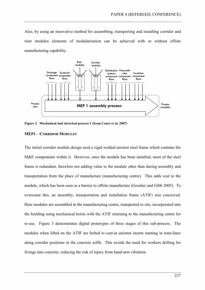
PAPER 4 (REFEREED, CONFERENCE)
237
Also, by using an innovative method for assembling, transporting and installing corridor and
riser modules elements of modularisation can be achieved with or without offsite
manufacturing capability.
MEP 1 assembly processProcess start
Process completeMEP 1 assembly process
Process start
Process complete
Drainage componentflows
Drainage componentflows
Distribution systems componentflows
Distribution systems componentflows
Ductworkcomponentflows
Ductworkcomponentflows
RisermodulesRisermodules
Insulationcomponentflows
Insulationcomponentflows
CorridormodulesCorridormodules
Pneumatic tube
componentflows
Pneumatic tube
componentflows
Figure 2 Mechanical and electrical process 1 (from Court et al. 2007)
MEP1 – CORRIDOR MODULES
The initial corridor module design used a rigid welded unistrut steel frame which contains the
M&E components within it. However, once the module has been installed, most of the steel
frame is redundant, therefore not adding value to the module other than during assembly and
transportation from the place of manufacture (manufacturing centre). This adds cost to the
module, which has been seen as a barrier to offsite manufacture (Goodier and Gibb 2005). To
overcome this, an assembly, transportation and installation frame (ATIF) was conceived.
Here modules are assembled in the manufacturing centre, transported to site, incorporated into
the building using mechanical hoists with the ATIF returning to the manufacturing centre for
re-use. Figure 3 demonstrates digital prototypes of three stages of this sub-process. The
modules when lifted on the ATIF are bolted to cast-in unistrut inserts running in tram-lines
along corridor positions in the concrete soffit. This avoids the need for workers drilling for
fixings into concrete, reducing the risk of injury from hand-arm vibration.
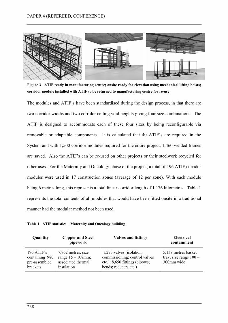
PAPER 4 (REFEREED, CONFERENCE)
238
Figure 3 ATIF ready in manufacturing centre; onsite ready for elevation using mechanical lifting hoists;
corridor module installed with ATIF to be returned to manufacturing centre for re-use
The modules and ATIF’s have been standardised during the design process, in that there are
two corridor widths and two corridor ceiling void heights giving four size combinations. The
ATIF is designed to accommodate each of these four sizes by being reconfigurable via
removable or adaptable components. It is calculated that 40 ATIF’s are required in the
System and with 1,500 corridor modules required for the entire project, 1,460 welded frames
are saved. Also the ATIF’s can be re-used on other projects or their steelwork recycled for
other uses. For the Maternity and Oncology phase of the project, a total of 196 ATIF corridor
modules were used in 17 construction zones (average of 12 per zone). With each module
being 6 metres long, this represents a total linear corridor length of 1.176 kilometres. Table 1
represents the total contents of all modules that would have been fitted onsite in a traditional
manner had the modular method not been used.
Table 1 ATIF statistics – Maternity and Oncology building
Quantity Copper and Steel
pipework
Valves and fittings Electrical
containment
196 ATIF’s
containing 980
pre-assembled
brackets
7,762 metres, size
range 15 – 108mm;
associated thermal
insulation
1,273 valves (isolation;
commissioning; control valves
etc.); 8,650 fittings (elbows;
bends; reducers etc.)
5,139 metres basket
tray, size range 100 –
300mm wide
PAPER 4 (REFEREED, CONFERENCE)
239
RESULTS
The planned onsite resource to elevate and install the modules is one pair of operatives from
the duct fitting team. To connect modules together was also one pair of operatives from the
composite pipework and electrical installation team.
This paper reports on the findings from this case study using the IMMPREST toolkit.
Pasquire et al. (2005) describe the IMMPREST toolkit as a tool for assessing the benefits
derived from the use of modular offsite assembly (hereafter known as S&P54) against what
would have been traditional installation methods. The benefits are classified into six
categories and these are cost; time; quality; health and safety; sustainability and site benefits.
The traditional option described in the assessment is: site installation of corridor mechanical
and electrical services using traditional methods (known hereafter as traditional) and the S&P
option described is: modularising corridor services using the ATIF method.
Cost Benefit Summary
The IMMPREST detailed cost worksheet analyses benefits in three areas;
construction/manufacturing costs, project costs and life-cycle costs. Overall, the detailed cost
worksheets (construction/manufacturing and project costs together) show a benefit in favour
of S&P of 8.62%. This is shown in table 2.
Basic material cost for S&P is higher due to offsite manufacturing centre overhead. This also
includes an amortised cost allowance for the use of the ATIF frames, considered as an asset to
the total project. Actual basic material cost for both methods is considered equal. Material
waste for traditional is estimated higher than S&P due to increased probability of site wastage
54 S&P meaning standardisation and preassembly as an IMMPREST term.
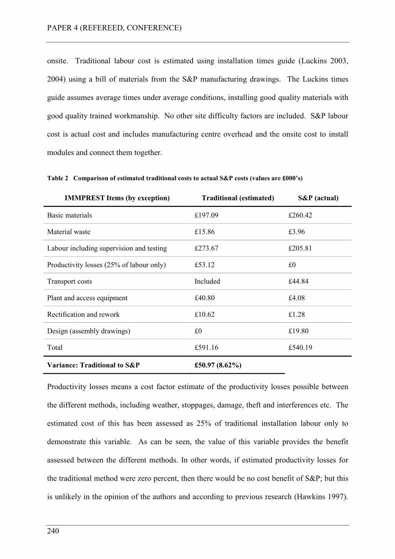
PAPER 4 (REFEREED, CONFERENCE)
240
onsite. Traditional labour cost is estimated using installation times guide (Luckins 2003,
2004) using a bill of materials from the S&P manufacturing drawings. The Luckins times
guide assumes average times under average conditions, installing good quality materials with
good quality trained workmanship. No other site difficulty factors are included. S&P labour
cost is actual cost and includes manufacturing centre overhead and the onsite cost to install
modules and connect them together.
Table 2 Comparison of estimated traditional costs to actual S&P costs (values are £000’s)
IMMPREST Items (by exception) Traditional (estimated) S&P (actual)
Basic materials £197.09 £260.42
Material waste £15.86 £3.96
Labour including supervision and testing £273.67 £205.81
Productivity losses (25% of labour only) £53.12 £0
Transport costs Included £44.84
Plant and access equipment £40.80 £4.08
Rectification and rework £10.62 £1.28
Design (assembly drawings) £0 £19.80
Total £591.16 £540.19
Variance: Traditional to S&P £50.97 (8.62%)
Productivity losses means a cost factor estimate of the productivity losses possible between
the different methods, including weather, stoppages, damage, theft and interferences etc. The
estimated cost of this has been assessed as 25% of traditional installation labour only to
demonstrate this variable. As can be seen, the value of this variable provides the benefit
assessed between the different methods. In other words, if estimated productivity losses for
the traditional method were zero percent, then there would be no cost benefit of S&P; but this
is unlikely in the opinion of the authors and according to previous research (Hawkins 1997).
PAPER 4 (REFEREED, CONFERENCE)
241
This measured average overall productivity as 37% on the UK projects monitored. Any actual
cost for S&P loss of productivity is included in the S&P labour cost.
More plant and equipment is estimated for the traditional method and is required for each
trade cycling through the site carrying out their work. Transport costs for traditional method
is included in basic material costs, with much higher actual cost necessary for S&P. This is
required to deliver the ATIF modules from the manufacturing centre to site; and then a back-
haul cost to return ATIF’s to the manufacturing centre for re-use. Assembly drawings are
required for the S&P method for manufacturing purposes; these are not required for the
traditional method.
The life-cycle summary did not show any significant benefit from S&P as the categories
analysed were either similar or moderately better than a traditional approach.
TIME BENEFIT SUMMARY
The IMMPREST detailed time worksheet analyses benefits in two areas; offsite and pre-
construction activities, and onsite activities. For offsite and pre-construction activities a zero
percent benefit with moderate confidence is reported. This zero benefit is a result of equal
durations for all pre-construction phases of the project. Whilst an additional week per
construction zone is required for ATIF module assembly drawings driven from the 3D model,
this is offset by the work required to produce paper-space drawing for a traditional onsite
method. These would require time to add setting out and invert dimensions and the like.
Further to this lead-in times for offsite manufacture of ATIF’s is one week, as these are
simple assembly processes of pre-made components into the assembly frame. Lead-in times
to acquire site materials would also be one week.
PAPER 4 (REFEREED, CONFERENCE)
242
For onsite activities, the summary shows a time benefit in favour of S&P with high
confidence. Here, total site establishment is considered equal, as the start and end project date
remains the same. A benefit is derived from shorter overall cycle-times to install ATIF
modules versus the traditional method. The quantity of ATIF’s per construction zone is 12
(average), and these are installed within the Week-Beat allocation. With 17 construction
zones, a 17 week overall cycle-time is required. Whilst the traditional method would utilise a
Week-Beat method, more onsite trades are required to cycle through each construction zone
to complete their work, therefore taking longer. This has been estimated as follows: one week
bracket assembly; three weeks pipe work assembly including one week testing; one week
pipework insulation; and one week electrical containment installation. Overall cycle-time for
the traditional method is five weeks, giving an overall cycle time for 17 construction zones of
22 weeks (using a Week-Beat method). Finally, an additional week per construction zone is
required to site test the traditional method, whereas the ATIF modules are tested offsite, this
also provides a benefit.
QUALITY BENEFIT SUMMARY
The IMMPREST detailed quality worksheet analyses benefits in two areas;
construction/manufacture quality and life-cycle quality. For construction/manufacture quality
the assessment found that the project should benefit from an S&P approach with high
confidence. The main drivers for this benefit (by exception) are; for category relating to the
level of quality a significantly better grade of finish and degree of certainty of product quality
was found. For the defects and damage category a significantly lower level of defects (failure
to achieve the specifications, or damage to the product before final completion) was found.
For customer requirements category; a significantly better visual appearance of the finished
product and significantly lower level of customer / user complaints was found. The life-cycle
PAPER 4 (REFEREED, CONFERENCE)
243
summary did not show any significant benefit from S&P as the categories analysed were
either similar or moderately better than a traditional approach.
HEALTH AND SAFETY BENEFIT SUMMARY
Firstly, there were zero accidents (minor or reportable) associated with this work, either onsite
or offsite at the manufacturing centre. The IMMPREST detailed health and safety worksheet
analyses benefits in two areas; construction/manufacture health and safety and life-cycle
health and safety. For construction/manufacture health and safety it was found that the
project should benefit from the S&P approach with high confidence. The biggest driver for
improved health and safety with S&P is the fewer persons (H&S ratios category) required
onsite to install and connect together the ATIF modules. In total S&P required 1,568 mans
hours onsite, compared to 22,320 man hours estimated for traditional, all working at height
(safety category – persons working in difficult or dangerous conditions). This equates to 93%
less hours onsite using the S&P approach instead of the traditional. Finally, S&P has
significantly lower housekeeping issues; the degree to which activity and process contributes
to site waste and untidiness.
Life-cycle summary did not show any significant benefit from the S&P approach as the
categories analysed were either similar or moderately better than a traditional approach.
SUSTAINABILITY BENEFIT SUMMARY
The IMMPREST detailed sustainability worksheet analyses benefits in two areas;
sustainability issues and respect for people principles. For sustainability issues, the summary
finds that the project may benefit from an S&P approach with high confidence. Most items
are similar, for ecological impact and physical pollution; moderately better, for waste and
materials; moderately lower, for energy consumption, water consumption and community
PAPER 4 (REFEREED, CONFERENCE)
244
pollution; and moderately higher, for transport. However, one item was significantly lower,
and this was the general impact on the local community, the driver for this being the much
reduced level of operatives required on site along with associated car parking in the adjacent
residential areas due to limited or no car parking facilities onsite. For the respect for people
principles, the assessment found that the project should benefit from S&P with high
confidence. The main drivers for the benefit (by exception) are: for safety; a significantly
lower risk of reportable accidents for S&P; for working hours (long working hours contribute
to accidents, poor morale and efficiencies) and travelling time (travel time has an impact on
staff morale, productivity and contributes to road traffic accidents which result in lost time),
the assessment was significantly lower for S&P.
SITE BENEFIT SUMMARY
The IMMPREST detailed site benefits worksheet analyses site issues as constraints that are to
be assessed as either high, low or none and these are; site space and storage, multi-trade
interfaces, skilled labour, access to site (including delivery), live working conditions,
movement of units onsite and restrictions (on site work by external parties). The assessment
found that all category constraints may be mitigated by S&P with high confidence. The main
drivers for this are limited site space available for site storage of materials; a traditional
method would require many interfacing trades onsite to undertake the work; shortage of
skilled labour (Goodier and Gibb 2005); limited site access (live hospital environment);
limited movement of vehicles onsite and restrictions on site work due to local constraints (car
parking in adjacent neighbourhoods etc.).
CONCLUSIONS
The IMMPREST assessment undertaken has found that overall the use of ATIF’s to
modularise corridor mechanical and electrical distribution systems has benefitted the project
PAPER 4 (REFEREED, CONFERENCE)
245
with high confidence. The primary objective of this research project for the company is to
improve site operations, making them safer for the worker, and improving efficiency and
productivity. The results have shown that by using ATIF’s to modularise corridor services;
zero accidents occurred either onsite or offsite associated with this work; an 8.62% cost
saving is achieved over an estimation of traditional methods (with an estimated productivity
loss of 25% of traditional method site labour); a higher quality is achieved with less site
rework; 93% less hours are required onsite for the S&P method (much fewer operatives
onsite at risk of injury); a shorter overall cycle-time is required to complete the installation in
17 construction zones, 17 weeks versus 22 weeks (23% reduced cycle-time), with higher
confidence in S&P.
The ATIF S&P method therefore has been shown to improve health, safety and productivity
for onsite operatives, with much fewer being required, mitigating the further risk that the
industry faces with shortage of skilled labour. Finally, cost certainty for this element is
achieved because of the known actual offsite costs and much higher certainty of resultant
onsite costs. A traditional method would not, in the opinion of the authors, achieve full
productivity, therefore whatever productivity loss is estimated, a cost benefit will be achieved
with an S&P method. If this method saves health and safety risks, costs less and takes less
time, why would you not do it?
FURTHER RESEARCH
Further research is currently being conducted to finalise the implementation of the
Construction System on the case study project and to conduct analysis of the overall results,
this being the final phase of research. The results emerging from this will be reported in
future research papers.
PAPER 4 (REFEREED, CONFERENCE)
246
REFERENCES
Court, P., Pasquire, C., Gibb, A.G.F., and Bower, D., (2005). Lean as an antidote to labour
cost escalation on complex mechanical and electrical projects. Proceedings of the 13th
annual conference of the International Group for Lean Construction, Sydney,
Australia, 2005.
Court, P., Pasquire, C., Gibb, A.G.F., and Bower, D., (2006). Design of a Lean and agile
Construction System for a large and complex mechanical and electrical project.
Proceedings of the 14th annual conference of the International Group for Lean
Construction, Santiago, Chile, 2006.
Court, P., Pasquire, C., Gibb, A.G.F., and Bower, D., (2007). Transforming traditional
construction into a modern process of assembly using Construction Physics.
Proceedings of the 15th annual conference of the International Group for Lean
Construction, East Lansing, USA, 2007.
Gibb, A.G.F., (2006) (Keynote). Occupational health: slow accidents need solutions fast, in
Fang, Choudry & Hinze (eds), Global Unity for Safety & Health in Construction, Proc.
of CIBW99 Int. Conf., June 2006, Beijing, Tsinghua University Press, pp. 22-33.
Goodier, C.I., Gibb, A.G.F., (2005). Barriers and opportunities for offsite in the UK.”
Systematic innovation in the management of projects and processes. Abdul Samad
Kazi (ed), cib Helsinki international joint symposium, pp. 148-158, ISBN 952 5004 64
3.
Hawkins, G., (1997). Improving M&E site productivity, BSRIA Technical Note TN 14/97,
The Building Services Research and Information Association, Bracknell, UK.
PAPER 4 (REFEREED, CONFERENCE)
247
Hawkins, G., (2002). Site Productivity – 2002. A guide to the uptake of improvements,
BSRIA technical note TN 13/2002, The Building Services Research and Information
Association, Bracknell, UK.
Health and Safety Executive, (2000). Backs for the future: safe manual handling in
construction, HSE books, Norwich, UK.
Health and Safety Executive, (2007). Health and safety in the construction industry.
<http://www.hse.gov.uk/construction/index.htm> (Mar. 4, 2007)
Health and Safety Executive, (2007a). Better backs in construction.
<http://www.hse.gov.uk/construction/backs/index.htm> (Mar. 4, 2007).
Health and Safety Executive, (2007b). Musculoskeletal disorders – HSE and MSD’s.
<http://www.hse.gov.uk/msd/hsemsd.htm> (Mar. 4, 2007).
Luckins, (2003). Mechanical installation times guide for estimators. Trade Services
Information Limited, 2003, England.
Luckins, (2003). Electrical installation times guide for estimators. Trade Services Information
Limited, 2003, England. ISBN 0 5912985 3 4.
Mawdesley, M.J., and Long, G., (2002). “Prefabrication for Lean building services
distribution.” Proc. Tenth Annual Conf. of the Int. Group for Lean Construction
(IGLC-10), Gramado, Brazil.
Pasquire, C.L., and Connolly, G.E., (2002). Leaner construction through offsite
manufacturing. Proc. Tenth Annual Conf. of the Int. Group for Lean Construction
(IGLC-10), Gramado, Brazil.
PAPER 4 (REFEREED, CONFERENCE)
248
Pasquire, C.L., and Connolly, G.E., (2003). Design for manufacture and assembly. Proc.
Eleventh Annual Conf. of the International Group for Lean Construction (IGLC-11),
Blacksburg, Virginia.
Pasquire, C., Gibb, A.G.F., and Blissmass, N., (2005). What should you really measure if you
want to compare prefabrication with traditional construction?” Proceedings of the 13th
annual conference of the International Group for Lean Construction, Sydney,
Australia, 2005.
Thomas, H. R., Horman, M. J., and de Souza, U. E. L., (2005). Symbiotic crew relationships
and labor flow. J. Constr. Eng. Manage., 130(6), 908-917.
PAPER 5 (JOURNAL, PUBLISHED)
249
APPENDIX E PAPER 5 (JOURNAL, PUBLISHED)
Court, P., Pasquire, C., Gibb, A.G.F., (2009). A Lean and agile Construction System as a set
of countermeasures to improve Health, Safety and productivity in mechanical and electrical
construction. Lean Construction Journal, November 2009.

PAPER 5 (JOURNAL, PUBLISHED)
250
PAPER 5 (JOURNAL, PUBLISHED)
251
A LEAN AND AGILE CONSTRUCTION SYSTEM AS A SET OF
COUNTERMEASURES TO IMPROVE HEALTH, SAFETY
AND PRODUCTIVITY IN MECHANICAL AND ELECTRICAL
CONSTRUCTION.
Peter F.Court, Christine Pasquire, Alistair Gibb
This paper presents certain aspects of the findings of a research project to develop and
implement a Lean and agile mechanical and electrical (M&E) Construction System on a case
study project. The objective of the research project for the sponsor company is to improve its
projects site operations making them safer for the worker and improving efficiency and
productivity by overcoming the problems and issues that it faces in the M&E industry within
the UK construction sector.
The research finds that using the System on the case study project, and when compared to a
traditional method, a 37% reduction in onsite labour was achieved; no time slippage occurred
during onsite assembly to delay or disrupt other trades; less workers onsite were exposed to
lower health and safety risks from site operations leading to zero reportable accidents; good
ergonomics was achieved by focussing on workplace design thus improving workers
wellbeing; an improved quality of work was achieved for those required on site carrying out
simpler assembly tasks; productivity gains were achieved by eliminating process waste; a 7%
direct labour reduction was achieved leading to no labour cost escalation that otherwise could
have occurred further reducing the risk of labour cost escalation. Significantly, an overall
productivity of 116% was achieved using the Construction System which compares
favourably to the Building Services Research and Information Association (BSRIA) findings
PAPER 5 (JOURNAL, PUBLISHED)
252
of an average overall productivity of only 37% when compared to observed best practice for
the projects in that case study research. Also, no compression of the commissioning period
occurred with the built facility being handed over to the customer on time.
KEY WORDS Construction System, countermeasures, Last Planner, Health and Safety,
productivity.
INTRODUCTION
This is a practical paper drawn from a collaborative research project (the research project)
being undertaken at the Centre for Innovative Collaborative Engineering at Loughborough
University, UK. The programme is funded by the Engineering and Physical Sciences
Research Council (EPSRC) and is sponsored by a major UK mechanical and electrical
contractor (the company). The research project has specific objectives, which will be capable
of making a significant contribution to the performance of the sponsor company. The
research problem that this project is designed to overcome is that of the poor health, safety
and productivity performance that the company faces in UK construction. These problems
are described in this paper.
The researcher is developing a Construction System for the company to overcome these
problems and therefore to improve the performance of its projects. This paper is the sixth in a
series of papers reporting on the design and implementation of the System and is a
continuation of the already published findings and results of the same methodology and case
study project. This paper presents the health, safety and productivity findings measured as the
outcome of implementing the System on the case study project during the sample period. As
a point of note, the researcher is the M&E Project Leader for the company on the case study
PAPER 5 (JOURNAL, PUBLISHED)
253
project and is submitting these papers as part of the award for an Engineering Doctorate being
studied at Loughborough University in the United Kingdom.
RESEARCH PROJECT OBJECTIVES
As stated the objective of this project for the company is to design and implement a new way
of working on site to improve site operations, making them safer for the worker and to
improve productivity. Safety is at the core of the company and according to the Business
Leaders “…it is an absolute right for people to return home safely at the end of a productive
day’s work,” and “failure to do so renders the company valueless.” The key words here
being safely and productive, these are therefore at the core of this research project, which is to
design and implement a way of working on site that will satisfy these objectives by
overcoming the problems and issues that it faces.
UNDERPINNING PURPOSE
The purpose of designing and implementing this Construction System is to specifically
understand and to overcome the issues that face M&E construction in terms of historically
poor health, safety and productivity outcomes on projects. The System is a specifically
designed construction methodology to act as a set of countermeasures55 to what would
otherwise occur had this not been done. The System accepts existing research into the issues
faced in construction (specifically M&E construction) and therefore does not seek to replicate
this. Consider it as designing and implementing a new production process for M&E
construction using innovative techniques drawn from extensive research, observation,
experience, lessons learned, continuous improvement, and new technology. The main issues
55 A countermeasure is defined by Oxford English Dictionary (2009) as an action taken to counteract a
danger or threat. The threat to the company is the primary issues faced in UK construction, i.e. the
research problem.
PAPER 5 (JOURNAL, PUBLISHED)
254
that the System is designed to countermeasure have been discussed in previous research
papers together with how the System works to overcome them. These primary issues were
identified as an outcome of a thorough literature review and the particular research process
undertaken. These are now described.
THE RESEARCH PROCESS
The initial phase of the research process undertaken involved a literature review,
observational studies, and ethnography to establish the current state; how things are done
today which sets a foundation of understanding the research problem and what to do to
overcome it. The key findings of this phase and the issues that the company faces revolve
principally around health and safety factors (HSE 2000, 2007, 2007a, 2007b, Gibb 2006);
space availability issues (Winch and North 2006, Akinci et al. 2002, 2002a, Guo 2002);
productivity issues (Hawkins 1997, 2002, Wilson 2000); crew conflict issues (Howell et al.
1993, Thomas et al. 2005 and Horman et al. 2006) and worker skills issues (Goodier and Gibb
2005). The primary issues and their source are summarised in table 1.
These issues represent the basic underpinning reasons for the company to improve its site
operations as it is indeed not immune from these. The next phase of research was conducted
to be able to design a set of countermeasures to overcome the issues identified in table 1.
This phase focussed on research and learning from manufacturing, and in particular Lean and
agile methods in use today. The research and learning undertaken has been used to develop a
theoretical Construction System that incorporates manufacturing methods such as modular
assembly; postponement; reflective manufacture; pulse-driven scheduling and ABC parts
classification.

PAPER 5 (JOURNAL, PUBLISHED)
255
Table 1 Summary of primary issues
Primary issues Source
Manual handling injuries caused by repetitive and heavy
lifting; bending and twisting; repeating actions too frequently;
uncomfortable working position; exerting too much force;
working too long without breaks; adverse working
environment and psychosocial factors.
Health and Safety executive (2007a,
2007b).
Slow accidents caused by health factors. The period over
which the incident occurs may be longer but the result is the
same, a worker gets injured but it takes longer.
Gibb (2006).
Site congestion generates hazards and reduces output. Winch and North (2006); Akinci et
al. (2002a, 2002b); Guo (2002);
observational studies; ethnography.
Subcycle and symbiotic crew relationships delay each other. Howell et al. (1993); Thomas et al.
(2004).
Too much site cutting and elevation of parts into position. Hawkins (1997); observational
studies; ethnography.
Poorly conceived materials handling strategies. Hawkins (1997); observational
studies; ethnography.
Very poor levels of housekeeping. Hawkins (1997); observational
studies; ethnography.
Outdated components and processes. Wilson (2000); Hawkins (2002);
observational studies; ethnography.
Site workers in short supply or inappropriately skilled. Goodier and Gibb (2005).
Limited, unplanned or improvised workplace organisation,
workbenches, and equipment.
Observational studies; ethnography.
Assembly work carried out on the floor or on whatever came
to hand.
Observational studies; ethnography.
Nowhere to hang drawings or other information. Observational studies; ethnography.
Scaffold systems provided that had to be accessed by climbing
a ladder and opening flaps, with no facilities to store materials
or tools.
Observational studies; ethnography.
Tools only provided by the tradesmen - they had what they
had irrespective of their suitability.
Observational studies; ethnography.
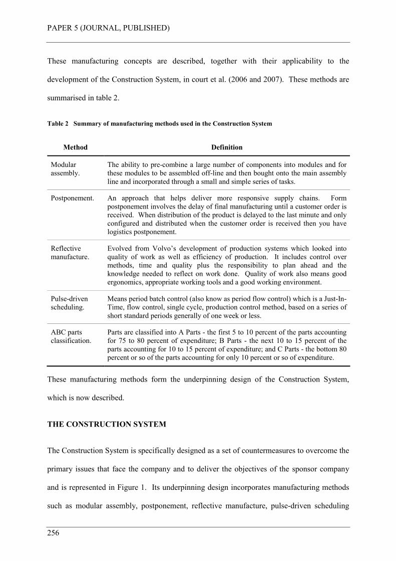
PAPER 5 (JOURNAL, PUBLISHED)
256
These manufacturing concepts are described, together with their applicability to the
development of the Construction System, in court et al. (2006 and 2007). These methods are
summarised in table 2.
Table 2 Summary of manufacturing methods used in the Construction System
Method Definition
Modular
assembly.
The ability to pre-combine a large number of components into modules and for
these modules to be assembled off-line and then bought onto the main assembly
line and incorporated through a small and simple series of tasks.
Postponement. An approach that helps deliver more responsive supply chains. Form
postponement involves the delay of final manufacturing until a customer order is
received. When distribution of the product is delayed to the last minute and only
configured and distributed when the customer order is received then you have
logistics postponement.
Reflective
manufacture.
Evolved from Volvo’s development of production systems which looked into
quality of work as well as efficiency of production. It includes control over
methods, time and quality plus the responsibility to plan ahead and the
knowledge needed to reflect on work done. Quality of work also means good
ergonomics, appropriate working tools and a good working environment.
Pulse-driven
scheduling.
Means period batch control (also know as period flow control) which is a Just-In-
Time, flow control, single cycle, production control method, based on a series of
short standard periods generally of one week or less.
ABC parts
classification.
Parts are classified into A Parts - the first 5 to 10 percent of the parts accounting
for 75 to 80 percent of expenditure; B Parts - the next 10 to 15 percent of the
parts accounting for 10 to 15 percent of expenditure; and C Parts - the bottom 80
percent or so of the parts accounting for only 10 percent or so of expenditure.
These manufacturing methods form the underpinning design of the Construction System,
which is now described.
THE CONSTRUCTION SYSTEM
The Construction System is specifically designed as a set of countermeasures to overcome the
primary issues that face the company and to deliver the objectives of the sponsor company
and is represented in Figure 1. Its underpinning design incorporates manufacturing methods
such as modular assembly, postponement, reflective manufacture, pulse-driven scheduling
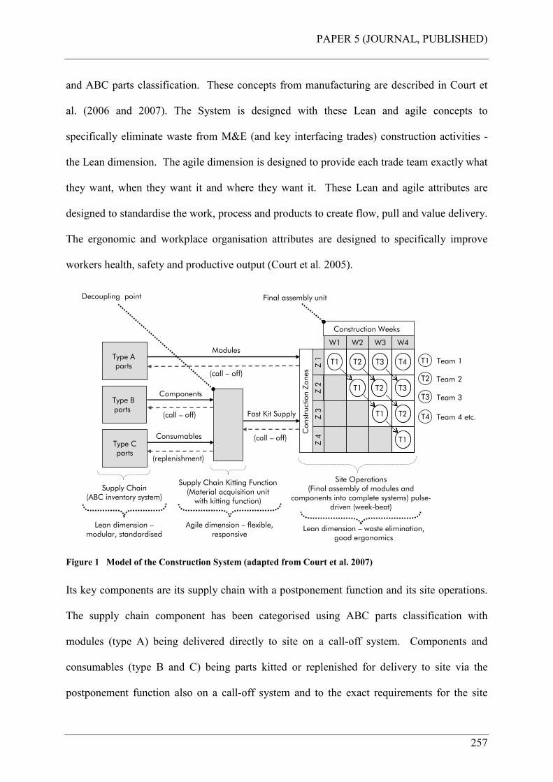
PAPER 5 (JOURNAL, PUBLISHED)
257
and ABC parts classification. These concepts from manufacturing are described in Court et
al. (2006 and 2007). The System is designed with these Lean and agile concepts to
specifically eliminate waste from M&E (and key interfacing trades) construction activities -
the Lean dimension. The agile dimension is designed to provide each trade team exactly what
they want, when they want it and where they want it. These Lean and agile attributes are
designed to standardise the work, process and products to create flow, pull and value delivery.
The ergonomic and workplace organisation attributes are designed to specifically improve
workers health, safety and productive output (Court et al. 2005).
Type A parts
Type B parts
Type Cparts
Supply Chain(ABC inventory system)
Fast Kit Supply(call – off)
Supply Chain Kitting Function(Material acquisition unit with kitting function)
(replenishment)
Modules
(call – off)
Components
Consumables
(call – off)
Z 2
W1 W2 W3 W4
Z 1
Z 3
Z 4
T1 T2 T3 T4
T1 T2
T1 T2
T3
T1
Z 2
W1 W2 W3 W4
Z 1
Z 3
Z 4
T1 T2 T3 T4
T1 T2
T1 T2
T3
T1
W1 W2 W3 W4
Z 1
Z 3
Z 4
T1 T2 T3 T4
T1 T2
T1 T2
T3
T1
Construction Zones
Construction Weeks
Team 1
Team 2
Team 3
T1
Site Operations (Final assembly of modules and
components into complete systems) pulse-driven (week-beat)
Team 4 etc.
T2
T3
T4
Final assembly unitDecoupling point
Agile dimension – flexible, responsive
Lean dimension –modular, standardised
Lean dimension – waste elimination, good ergonomics
Figure 1 Model of the Construction System (adapted from Court et al. 2007)
Its key components are its supply chain with a postponement function and its site operations.
The supply chain component has been categorised using ABC parts classification with
modules (type A) being delivered directly to site on a call-off system. Components and
consumables (type B and C) being parts kitted or replenished for delivery to site via the
postponement function also on a call-off system and to the exact requirements for the site
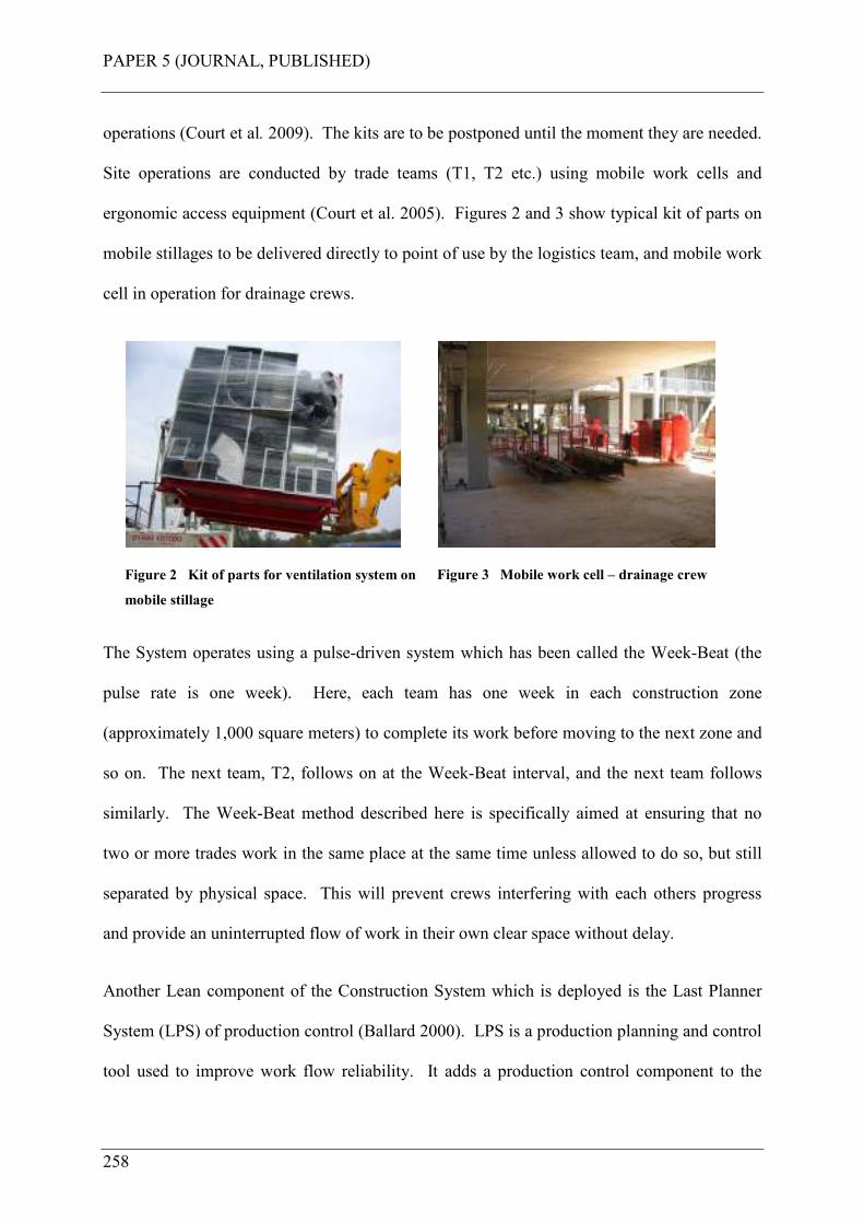
PAPER 5 (JOURNAL, PUBLISHED)
258
operations (Court et al. 2009). The kits are to be postponed until the moment they are needed.
Site operations are conducted by trade teams (T1, T2 etc.) using mobile work cells and
ergonomic access equipment (Court et al. 2005). Figures 2 and 3 show typical kit of parts on
mobile stillages to be delivered directly to point of use by the logistics team, and mobile work
cell in operation for drainage crews.
Figure 2 Kit of parts for ventilation system on
mobile stillage
Figure 3 Mobile work cell – drainage crew
The System operates using a pulse-driven system which has been called the Week-Beat (the
pulse rate is one week). Here, each team has one week in each construction zone
(approximately 1,000 square meters) to complete its work before moving to the next zone and
so on. The next team, T2, follows on at the Week-Beat interval, and the next team follows
similarly. The Week-Beat method described here is specifically aimed at ensuring that no
two or more trades work in the same place at the same time unless allowed to do so, but still
separated by physical space. This will prevent crews interfering with each others progress
and provide an uninterrupted flow of work in their own clear space without delay.
Another Lean component of the Construction System which is deployed is the Last Planner
System (LPS) of production control (Ballard 2000). LPS is a production planning and control
tool used to improve work flow reliability. It adds a production control component to the
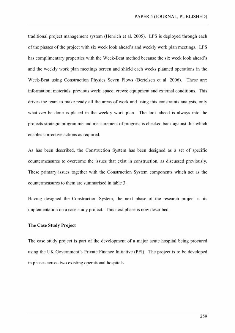
PAPER 5 (JOURNAL, PUBLISHED)
259
traditional project management system (Henrich et al. 2005). LPS is deployed through each
of the phases of the project with six week look ahead’s and weekly work plan meetings. LPS
has complimentary properties with the Week-Beat method because the six week look ahead’s
and the weekly work plan meetings screen and shield each weeks planned operations in the
Week-Beat using Construction Physics Seven Flows (Bertelsen et al. 2006). These are:
information; materials; previous work; space; crews; equipment and external conditions. This
drives the team to make ready all the areas of work and using this constraints analysis, only
what can be done is placed in the weekly work plan. The look ahead is always into the
projects strategic programme and measurement of progress is checked back against this which
enables corrective actions as required.
As has been described, the Construction System has been designed as a set of specific
countermeasures to overcome the issues that exist in construction, as discussed previously.
These primary issues together with the Construction System components which act as the
countermeasures to them are summarised in table 3.
Having designed the Construction System, the next phase of the research project is its
implementation on a case study project. This next phase is now described.
The Case Study Project
The case study project is part of the development of a major acute hospital being procured
using the UK Government’s Private Finance Initiative (PFI). The project is to be developed
in phases across two existing operational hospitals.

PAPER 5 (JOURNAL, PUBLISHED)
260
Table 3 Issues and Countermeasures
Primary issues Construction System countermeasures
Manual handling injuries caused by repetitive and heavy
lifting; bending and twisting; repeating actions too frequently;
uncomfortable working position; exerting too much force;
working too long without breaks; adverse working
environment and psychosocial factors.
Modular assembly with mechanical lifting
aids; trained manual handlers in logistics
team; materials in purpose made stillages,
trolleys and roll-cages.
Slow accidents caused by health factors. The period over
which the incident occurs may be longer but the result is the
same, a worker gets injured but it takes longer.
Modular assembly; ergonomic workplace
design.
Site congestion generates hazards and reduces output. Week-Beat (trade separation); mobile work
cells; materials in mobile carriers.
Symbiotic crew relationships delay each other. These are tight
and closely dependant trades and these are more common in
mechanical, electrical, plumbing and finishing trades.
Week-Beat (trade separation).
Poorly conceived materials handling strategies. ABC parts classification; modular assembly;
Just-In-Time parts kitting.
Very poor levels of housekeeping. Physical waste managed by trained logistics
team.
Too much site cutting, drilling, assembly work and elevation
of parts into position.
Modular assembly with mechanical lifting
aids.
Outdated components and processes. ABC parts classification; push-fit
components; the Construction System; Last
Planner System.
Site workers in short supply or inappropriately skilled. Fewer workers required (modular offsite
assembly); lower skill mix needed for simpler
assembly tasks.
Limited, unplanned or improvised workplace organisation,
workbenches, and equipment.
Workplace organisation; mobile work cells.
Assembly work carried out on the floor or on whatever came
to hand.
Workplace organisation; mobile work cells.
Nowhere to hang drawings or other information. Workplace organisation; mobile work cells;
complete with mobile drawing boards.
Scaffold systems provided that had to be accessed by climbing
a ladder and opening flaps, with no facilities to store materials
or tools.
Ergonomic workplace design; walk-up
scaffold systems; scissor lifts.
Tools only provided by the tradesmen - they had what they had
irrespective of their suitability.
Appropriate working tools provided for all
tradesmen.
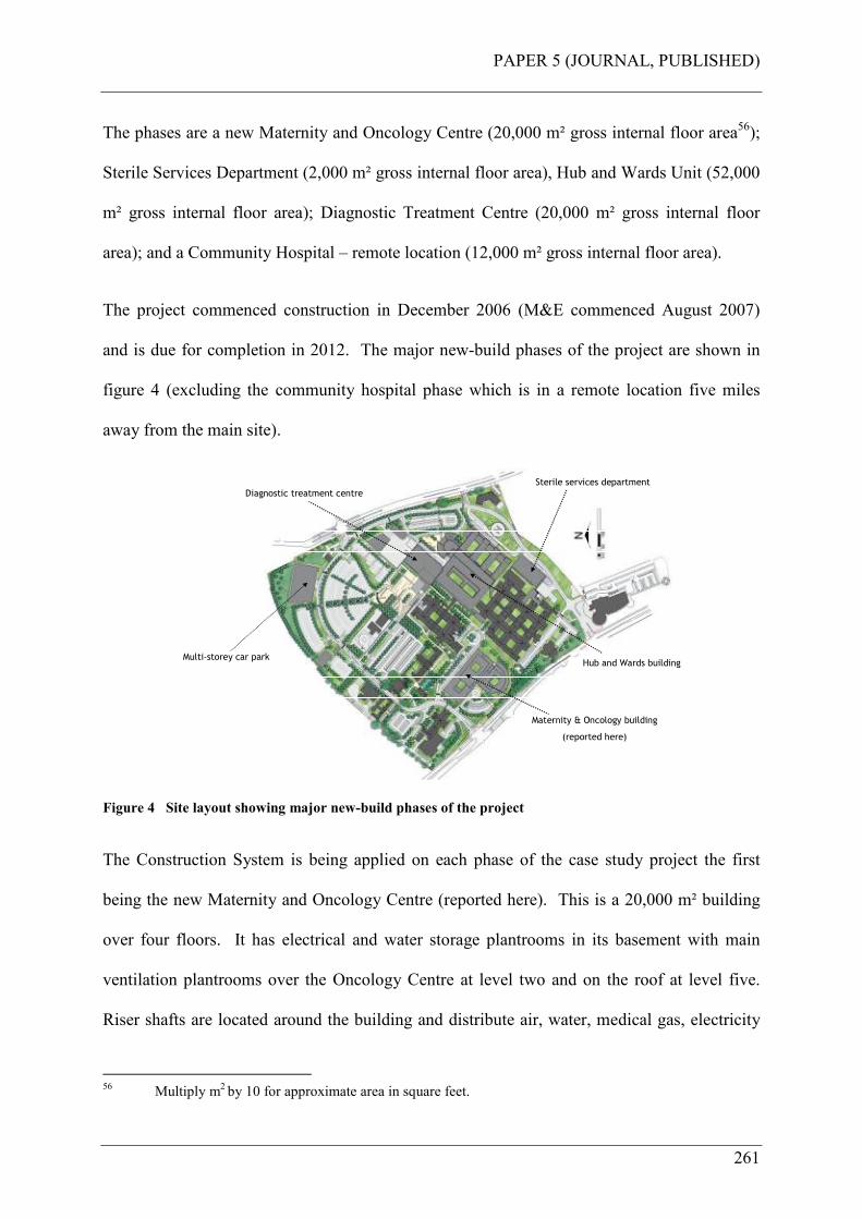
PAPER 5 (JOURNAL, PUBLISHED)
261
The phases are a new Maternity and Oncology Centre (20,000 m² gross internal floor area56);
Sterile Services Department (2,000 m² gross internal floor area), Hub and Wards Unit (52,000
m² gross internal floor area); Diagnostic Treatment Centre (20,000 m² gross internal floor
area); and a Community Hospital – remote location (12,000 m² gross internal floor area).
The project commenced construction in December 2006 (M&E commenced August 2007)
and is due for completion in 2012. The major new-build phases of the project are shown in
figure 4 (excluding the community hospital phase which is in a remote location five miles
away from the main site).
Multi-storey car park
Maternity & Oncology building
(reported here)
Sterile services department
Diagnostic treatment centre
Hub and Wards buildingMulti-storey car park
Figure 4 Site layout showing major new-build phases of the project
The Construction System is being applied on each phase of the case study project the first
being the new Maternity and Oncology Centre (reported here). This is a 20,000 m² building
over four floors. It has electrical and water storage plantrooms in its basement with main
ventilation plantrooms over the Oncology Centre at level two and on the roof at level five.
Riser shafts are located around the building and distribute air, water, medical gas, electricity
56 Multiply m
2 by 10 for approximate area in square feet.
PAPER 5 (JOURNAL, PUBLISHED)
262
and the like throughout the building to the various departments. Corridor ceiling voids
distribute the services from the riser shafts and then further into individual rooms and spaces,
again in the ceiling voids. Finally, services distribute inside dry-lined walls to points of use
such as electrical sockets, sinks, basins and bed-head units; everything you would expect to
see in a new and modern healthcare facility. The work itself was sequenced using the Week-
Beat method with close-scheduling as described in Court et al. (2007). This divided building
fabric processes (BFP) into BFP1-6, and mechanical and electrical processes (MEP) into
MEP1-5. This being everything required to start and complete all works in a construction
zone from a concrete shell to a complete hospital department (in 1,000 m² zones), excluding
testing and commissioning.
FINDINGS FROM IMPLEMENTATION
Assembly work commenced on the case study project in August 2007, with planned
completion of the installation activities, using the Construction System, at the beginning of
October 2008, a 63 week total cycle time including plantrooms (the sample period). This was
a target period set and was calculated following a review of the original planned period using
a traditional method, and applying this Lean and agile Construction System method to it.
This allows a clean commissioning period of 12 weeks (after BFP6 for the final construction
zone), with a five week buffer at the end of the programme period. All M&E processes
(MEP1-5) and plantrooms were complete at the end of October 2008 (week 66), with the
exception of the completion of major customer variations to the Oncology department and
working backlog items57. These customer variations resulting in approximately 60% of this
department (2 construction zones) having to be remodelled. Also, during the sample period
57 Working backlog is defined here as any minor incomplete works and rework items (such as snagging,
missed items of work etc).
PAPER 5 (JOURNAL, PUBLISHED)
263
(August 2007 to October 2008), 80% of electrical testing was complete; 80% of water
systems pressure testing was complete; 50% of extra low voltage system testing was complete
(building management systems, fire alarms etc.); 90% of voice and data system testing was
complete; and clean commissioning commenced (air and water system balancing). High
voltage power-on was achieved June 2008, and water-on to the building was achieved August
2008. Hand-over to the customer occurred in March 2009 for the Maternity facility and June
2009 for the Oncology facility, both on time. The findings are now reported for productivity
and labour cost, followed by Health and Safety findings.
PRODUCTIVITY AND LABOUR COSTS FINDINGS
The findings from the implementation have fallen into two sets. The first set was the results
and analysis of the benefits from the use of corridor modules in lieu of a traditional
installation method. This sub-process, the installation of corridor modules made offsite was
evaluated (once the work was complete) and reported in Court et al. (2008). Here 1,568
actual onsite hours were used elevating and connecting together a total of 196 modules,
compared to 22,320 hours estimated using traditional methods with various trade teams
completing the required work all working at height; a 93% reduction. An 8.62% cost benefit
is also reported. The second set combines this benefit with the results from the
implementation of the Construction System through all M&E processes and a final analysis
against overall expected benefits is now reported. Data collection to enable an assessment of
the benefits of the System is presented in figure 558. This presents a comparison of a
traditional approach, the Construction System (target Lean and agile) approach, actual hours
booked and actual hours booked minus unavoidable delays.
58 This analysis includes the onsite labour installing ATIF corridor modules described previously.

PAPER 5 (JOURNAL, PUBLISHED)
264
Curve A is the predicted cumulative labour hours and cycle time for a traditional installation
method (for all work including sub-contractors originated from the project cost plan).
202,800 hours with a 69 week cycle time. This curve is the benchmark against which the
Construction System method is measured (planned – curve B, and actual – curves C and D).
202,800 hours is derived from 2,535 pair man weeks which is calculated as follows:
2,535 (pair man weeks) x 2 (men per pair) x 40 (hours per week) = 202,800 hours.
0
50000
100000
150000
200000
250000
1 3 5 7 9 11 13 15 17 19 21 23 25 27 29 31 33 35 37 39 41 43 45 47 49 51 53 55 57 59 61 63 65 67 69
Week number
Cum
ula
tive h
ours
Curve A: Original cost plan cumulative hours: traditional approach
Curve B: Target cumulative hours: lean and agile approach
Curve C: Actual recorded cumulative hours (all trades)
Curve D: Available man hours: hours worked minus unavoidable delays (all trades)
Curve A
202,800 hrs
Week 69
Curve B
131,840 hrs
Week 63
Curve C
127,555 hrs
Week 66
Curve D
113,524 hrs
Week 66
Figure 5 Comparison of traditional approach, target Lean and agile approach, and actual hours booked,
with actual hours minus unavoidable delays shown
Curve B is the target predicted cumulative labour hours and cycle time after applying this
Construction System method. 131,84059 hours with a 63 week cycle time. This is the
expected outcome. 131,840 hours is derived from 1,648 pair man weeks which is calculated
as follows:
59 These are paid working hours and therefore already adjusted for unavoidable delays. Workers are paid
for a 45 hour week (excluding overtime if worked) and for their lunch break.
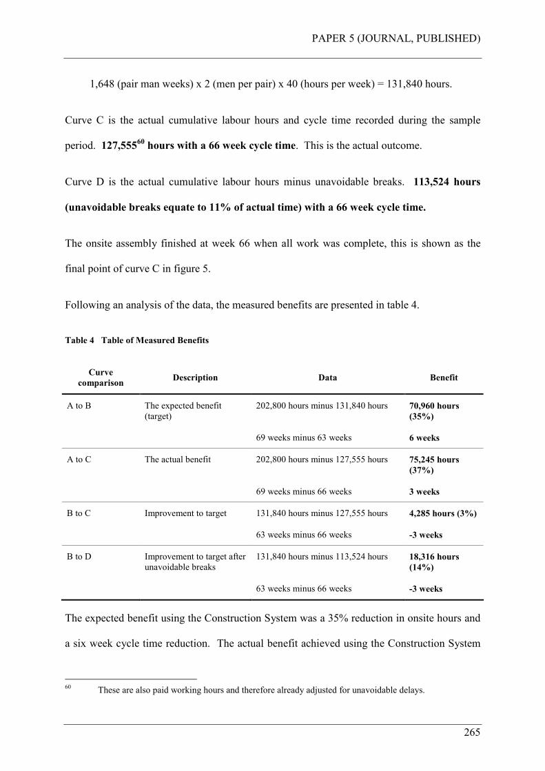
PAPER 5 (JOURNAL, PUBLISHED)
265
1,648 (pair man weeks) x 2 (men per pair) x 40 (hours per week) = 131,840 hours.
Curve C is the actual cumulative labour hours and cycle time recorded during the sample
period. 127,55560 hours with a 66 week cycle time. This is the actual outcome.
Curve D is the actual cumulative labour hours minus unavoidable breaks. 113,524 hours
(unavoidable breaks equate to 11% of actual time) with a 66 week cycle time.
The onsite assembly finished at week 66 when all work was complete, this is shown as the
final point of curve C in figure 5.
Following an analysis of the data, the measured benefits are presented in table 4.
Table 4 Table of Measured Benefits
Curve
comparison Description Data Benefit
A to B The expected benefit
(target)
202,800 hours minus 131,840 hours 70,960 hours
(35%)
69 weeks minus 63 weeks 6 weeks
A to C The actual benefit 202,800 hours minus 127,555 hours 75,245 hours
(37%)
69 weeks minus 66 weeks 3 weeks
B to C Improvement to target 131,840 hours minus 127,555 hours 4,285 hours (3%)
63 weeks minus 66 weeks -3 weeks
B to D Improvement to target after
unavoidable breaks
131,840 hours minus 113,524 hours 18,316 hours
(14%)
63 weeks minus 66 weeks -3 weeks
The expected benefit using the Construction System was a 35% reduction in onsite hours and
a six week cycle time reduction. The actual benefit achieved using the Construction System
60 These are also paid working hours and therefore already adjusted for unavoidable delays.
PAPER 5 (JOURNAL, PUBLISHED)
266
was a 37%61 reduction in onsite hours and a three week cycle time reduction. The actual
onsite hours improved from target by 3% (before unavoidable delays) but the expected cycle
time benefit of six weeks reduced to an actual of three weeks.
As described earlier this was due to the client changes to the Oncology department which
could not be accommodated in the target cycle time period. However, the labour hours for
this were absorbed within the actual hours recorded.
As described earlier, Hawkins (1997) reports that the UK projects monitored had an average
overall productivity of only 37% when compared to observed best practice. Using the method
presented by Hawkins, a similar overall productivity calculation was made. To achieve this,
available hours, as defined by Hawkins, were calculated (curve D). This represents recorded
actual man hours minus unavoidable delays such as lunch and tea breaks62. This represents
working hours available.
Overall productivity for the sample period was then calculated using the definition of overall
productivity in Hawkins (1997):
Overall Productivity = Output
Available Time
Where:
• OUTPUT is a measured quantity of installed material to a defined requirement. The
physical output is converted to units of time by employing an earned hour’s concept
based upon best practice installation times.
61 The 37% saving in onsite hours does not represent a saving in labour cost, as these hours contribute to
the labour budget for offsite manufactured components.
62 On average, this is one hour per day per worker: 30 minutes for lunch break; 15 minutes for morning
break; and 15 minutes for afternoon break.
PAPER 5 (JOURNAL, PUBLISHED)
267
• AVAILABE TIME is the total working day minus unavoidable delays such as lunch
and tea breaks.
Using this definition and hours from figure 4.42:
Overall Productivity = 131,840 hours = 116%
113,524 hours
Where:
• 131,840 hours is the total earned hours from the target Lean and agile approach (using
best practice installation times – the Construction System).
• 113,524 hours is the booked hours at completion (the sample period) minus
unavoidable delays (lunch and tea breaks), tracked using the System.
Therefore, an overall productivity of 116% was achieved using the System, which compares
favourably to the BSRIA findings of an average overall productivity of only 37% when
compared to observed best practice for the projects in that case study research. This
comparison needs to be viewed with a degree of caution, as the calculations shown reflects all
of the M&E installations on the case study project compared with BSRIA’s findings which
represent an average overall productivity for only ductwork, hot and chilled water pipework,
and cable management systems. This is treated by the author as a suitable benchmark from
which to measure the performance of the Construction System against.
Figure 4 includes time for all labour on site, which is the company’s own direct labour and
that of its sub-contractors. Of concern to the company was the impact that direct labour cost
escalation can have on the projects outturn profitability (Court et al. 2005). Therefore an
analysis of the company’s direct labour hours was also undertaken.
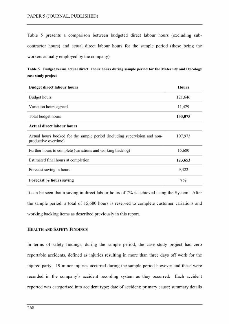
PAPER 5 (JOURNAL, PUBLISHED)
268
Table 5 presents a comparison between budgeted direct labour hours (excluding sub-
contractor hours) and actual direct labour hours for the sample period (these being the
workers actually employed by the company).
Table 5 Budget versus actual direct labour hours during sample period for the Maternity and Oncology
case study project
Budget direct labour hours Hours
Budget hours 121,646
Variation hours agreed 11,429
Total budget hours 133,075
Actual direct labour hours
Actual hours booked for the sample period (including supervision and non-
productive overtime)
107,973
Further hours to complete (variations and working backlog) 15,680
Estimated final hours at completion 123,653
Forecast saving in hours 9,422
Forecast % hours saving 7%
It can be seen that a saving in direct labour hours of 7% is achieved using the System. After
the sample period, a total of 15,680 hours is reserved to complete customer variations and
working backlog items as described previously in this report.
HEALTH AND SAFETY FINDINGS
In terms of safety findings, during the sample period, the case study project had zero
reportable accidents, defined as injuries resulting in more than three days off work for the
injured party. 19 minor injuries occurred during the sample period however and these were
recorded in the company’s accident recording system as they occurred. Each accident
reported was categorised into accident type; date of accident; primary cause; summary details
PAPER 5 (JOURNAL, PUBLISHED)
269
of accident; underlying causations; behaviours; injured body parts and injury type. An
overview of the place of accident, behaviours and primary causes are as follows;
Place of accident: 8 were not at the place work itself; 11 occurred at the place of work.
Behaviours: 2 were non-compliance with procedures; 9 were human error; 7 were personal
factors (carelessness, negligence etc.); 1 was a communication failure.
Primary cause: 3 were exposure to a harmful substance; 4 were slips/trips; 1 was contact
with plant and machinery; 3 were moving/falling object, 4 were “other”; 4 were
handling/lifting or carrying.
Whilst this is not an acceptable result given the interventions made with the Construction
System, manual work itself is still at the core of the System and this factor will keep exposing
the worker to the risk of minor injury. When studying these results, of particular note was the
workers behaviour, all but one of the accidents could have been avoided if the worker
complied with procedures, and paid more attention to avoid carelessness. This could be
overcome with more routine training given into the behavioural aspects of accident causation.
Human error could be reduced with more attention to further error-proofing the installation
work itself in the future.
From a health perspective, what benefits did the worker derive from good ergonomics and
workplace organisation for their wellbeing? According to Gibb (2006) the often delayed
onset of (health) conditions following exposure (to occupational health risks) should drive us
to look for solutions and do something about the problems. The interventions made in the
Construction System are about providing solutions to the health risks that would otherwise be
faced by the workers had these not been made. They are about protecting workers from work
related ailments such as MSD’s through better management and reduction of their exposure to
PAPER 5 (JOURNAL, PUBLISHED)
270
the causative factors (Gibb 2006). Occupational health is about risk management and in this
sense the risk management applied is the workplace organisation implemented in the
Construction System by undertaking the following:
• Providing cast-in inserts to avoid the need to drill overhead into concrete for large
fixings;
• Providing walk-up scaffolds or scissor lifts to avoid the need to climb ladders inside
traditional scaffold systems;
• Providing handling equipment and workbenches to avoid the need to bend over and
work or kneel on the floor. This decreases the physical workload of the worker
(Sillanpaa at al. 1997);
• Providing modular assemblies with mechanical aids to lift them. This avoids the need
to cut and manually elevate components overhead and working at height. This enables
employees to maintain an improved posture when connecting and testing the modules
(HSE 2000);
• Using mechanical lifting aids generally avoids the need for workers to manually elevate
components into position at high level;
• Providing mobile trolleys for tools, components and materials etc. This avoids the need
to carry and move things around manually;
• By having all materials stored in mobile trolleys at the workplace, exactly where they
are needed. This avoids the need to walk around looking for and carrying things to
where you need them;
• By providing simpler assembly tasks with pre-assembled quick-fit components. This
avoids workers being engaged in too much site cutting, drilling and assembly work and
elevation of parts into final position (Hawkins 1997).
PAPER 5 (JOURNAL, PUBLISHED)
271
The Construction System was an attempt to reduce the occupational health risks that
construction (M&E) workers face and to fit the work to the worker, as far as reasonably
practicable. Due to the time lag between the cause and effect in occupational ill health, it was
not possible to measure the benefit of these interventions in quantifiable terms within the
scope of this research project. Also, without significant medical research and ethical
compliance, there was no way of knowing a workers health condition prior to working on the
case study project. As such the need would have been to measure over 100 workers physical
condition prior to, and after their involvement, in the Construction System during the sample
period, and then draw conclusions from the findings. Whilst this was not within the scope of
this research project, testing the ergonomic interventions made is an area worthy of further
future research. The ergonomic equipment provided will, it is predicted, contribute to a
significant reduction in the muscular load on the workers as found by Sillanpaa et al. (1999).
What can be said, therefore, is that the Construction System will contribute in reducing the
causative problems that lead to work related ailments, and in this sense has workers wellbeing
and sending them home safely at the end of a productive days work at its core.
CONCLUSIONS
When compared to the benchmark traditional method 37% less onsite labour was achieved; a
three week reduction in construction zone cycle time was achieved, but more significant than
this is no time slippage occurring during construction to delay or disrupt other trades, and no
compression of the commissioning programme occurred as reported in Dicks (2002), with the
built facilities being handed over to the customer on time; 7% direct labour reduction was
achieved leading to no labour cost escalation as reported in Court et al. (2005); fewer workers
were exposed to lower health and safety risks from site operations leading to zero reportable
accidents; good ergonomics was achieved by focussing on workplace design thus improving
PAPER 5 (JOURNAL, PUBLISHED)
272
workers’ wellbeing; an improved quality of work was achieved for those on site by carrying
out simpler assembly tasks; productivity gains were achieved by eliminating process waste,
further reducing the risk of labour cost escalation; a significant overall productivity of 116%
is achieved using the Construction System which compares favourably to the BSRIA findings
of an average overall productivity of only 37% when compared to observed best practice
(Hawkins 1997) for the projects in that case study research (this being subject to the degree of
caution mentioned above). Indeed, according to the company, the findings from the
Construction System on this case study project, given its size and complexity, far exceed the
company’s expectations for performance improvement.
FURTHER RESEARCH
The next phase of research will be to continue the validation of the Construction System
through implementation and measurement of the results emerging from the final phases of the
case study project, this being the Hub, Wards and Diagnostic Treatment Centre, collectively
being the largest buildings of the project. Also, a change management methodology is being
devised to enable its implementation in these final phases, and further, into the sponsor
company’s wider organisation. This methodology uses Health and Safety performance as the
change driver that the worker commits to through personal choice not just for the sake of it, or
because senior management say so.
REFERENCES
Akinci, B., Fischer, M., Kunz, J., and Levitt, R., (2002). Representing work spaces
generically in construction method models. J. Constr. Eng. Manage., 128(4), 296-305.
Akinci, B., Fischer, M., Kunz, J., (2002a). Automated generation of work spaces required by
construction activities. J. Constr. Eng. Manage., 128(4), 306-315.
PAPER 5 (JOURNAL, PUBLISHED)
273
Bertelsen, S., Koskela, L., Henrich, G., and Rooke, J. (2006). Critical flow-towards a
construction flow theory. Proc., Fourteenth Annual Conf. of the Int. Group for Lean
Construction (IGLC-14), Santiago, Chile, 31-40.
Ballard, G., (2000). The Last Planner System of production control. PhD thesis, Department
of Civil Engineering, University of Birmingham, Birmingham, UK.
Cassell, C. and Symon, G., (2004). Essential guide to qualitative methods in organisational
research. SAGE publications, UK.
Coghlan, D. and Brannick, T., (2003). Doing action research in your own organisation.
SAGE publications, UK.
Court, P., Pasquire, C., Gibb, A.G.F., and Bower, D., (2005). Lean as an antidote to labour
cost escalation on complex mechanical and electrical projects. Proceedings of the 13th
annual conference of the International Group for Lean Construction, Sydney, Australia,
2005.
Court, P., Pasquire, C., Gibb, A.G.F., and Bower, D., (2006). Design of a Lean and agile
Construction System for a large and complex mechanical and electrical project.
Proceedings of the 14th annual conference of the International Group for Lean
Construction, Santiago, Chile, 2006.
Court, P., Pasquire, C., Gibb, A.G.F., and Bower, D., (2007). Transforming traditional
construction into a modern process of assembly using Construction Physics.
Proceedings of the 15th annual conference of the International Group for Lean
Construction, East Lansing, USA, 2007.
PAPER 5 (JOURNAL, PUBLISHED)
274
Court, P., Pasquire, C., Gibb, A.G.F., and Bower, D. (2008). Modular assembly in healthcare
construction – a mechanical and electrical case study. Proc., Sixteenth Annual Conf. of
the Int. Group for Lean Construction (IGLC-16), Manchester, United Kingdom, 521-
531.
Court, P., Pasquire, C., Gibb, A.G.F., (2009). Modular assembly with postponement to
improve health, safety and productivity in construction. J. Practice Periodical on
Structural Design and Construction., 14(2), 81-89.
Dicks, M., (2002). Commissioning management - how to Achieve a fully-functioning
building.” BSRIA application guide 5/2002. ISBN 0 86022 599-2.
Gibb, A.G.F., (2006) (Keynote). Occupational health: slow accidents need solutions fast, in
Fang, Choudry & Hinze (eds), Global Unity for Safety & Health in Construction, Proc.
of CIBW99 Int. Conf., June 2006, Beijing, Tsinghua University Press, pp. 22-33.
Goodier, C.I., Gibb, A.G.F., (2005). Barriers and opportunities for offsite in the UK.
Systematic Innovation in the Management of Projects and Processes. Abdul Samad
Kazi (ed), cib Helsinki international joint symposium, pp. 148-158, ISBN 952 5004 64
3.
Guo, S. J., (2002). Identification and resolution of work space conflicts in building
construction. J. Constr. Eng. Manage., 128(4), 287-295.
Hanna, A. S., Peterson, P., and Lee, M-J., (2002). Benchmarking productivity indicators for
electrical/mechanical projects. J. Constr. Eng. Manage., 128(4), 331-337.
Hawkins, G., (1997). Improving M&E site productivity, BSRIA technical note TN 14/97,
The Building Services Research and Information Association, Bracknell, UK.
PAPER 5 (JOURNAL, PUBLISHED)
275
Hawkins, G., (2002). Site Productivity – 2002. A guide to the uptake of improvements,
BSRIA technical note TN 13/2002, The Building Services Research and Information
Association, Bracknell, UK.
Health and Safety Executive, (2000). Backs for the future: safe manual handling in
construction, HSE books, Norwich, UK.
Health and Safety Executive, (2007). Health and safety in the construction industry.
<http://www.hse.gov.uk/construction/index.htm> (Mar. 4, 2007).
Health and Safety Executive, (2007a). Better backs in construction.
<http://www.hse.gov.uk/construction/backs/index.htm> (Mar. 4, 2007).
Health and Safety Executive, (2007b). “Musculoskeletal disorders – HSE and MSD’s.”
<http://www.hse.gov.uk/msd/hsemsd.htm> (Mar. 4, 2007).
Henrich, G., Tilley, P., Koskela, L., (2005). Context of production control in construction.
Proceedings of the 13th annual conference of the International Group for Lean
Construction, Sydney, Australia.
Horman, M. J., Orosz, M. P., and Riley, D. R. (2006). Sequence planning for electrical
construction. J. Constr. Eng. Manage., 132(4), 363-372.
Howell, G., Laufer, A., and Ballard, G. (1993). Interaction between subcycles – One key to
improved methods. J. Constr. Eng. Manage., 119(4), 714-728.
Sillanpaa, J., Lappalainen, J., Kaukiainen, A., Viljanen, M., Laippala, P., (1999). Decreasing
the physical workload of construction work with the use of four auxiliary handling
devices. International Journal of Industrial Ergonomics, no.24, 1999, 211-222.

PAPER 5 (JOURNAL, PUBLISHED)
276
Thomas, H. R., Horman, M. J., and de Souza, U. E. L., (2004). Symbiotic crew relationships
and labor flow. J. Constr. Eng. Manage., 130(6), 908-917.
Wilson, D., (2000). Innovative M&E installation, BSRIA ACT 9/2000, The Building
Services Research and Information Association, Bracknell, UK.
Winch, G. M., and North, S. (2006). Critical space analysis. J. Constr. Eng. Manage., 132(5),
473-481.
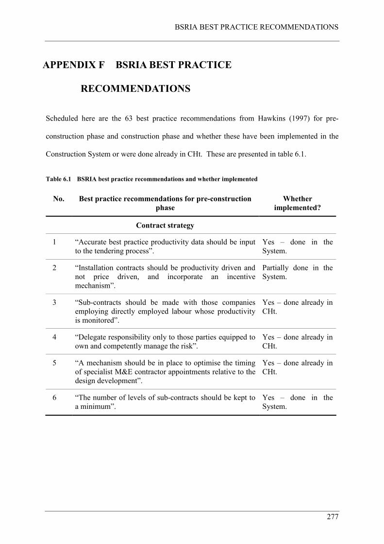
BSRIA BEST PRACTICE RECOMMENDATIONS
277
APPENDIX F BSRIA BEST PRACTICE
RECOMMENDATIONS
Scheduled here are the 63 best practice recommendations from Hawkins (1997) for pre-
construction phase and construction phase and whether these have been implemented in the
Construction System or were done already in CHt. These are presented in table 6.1.
Table 6.1 BSRIA best practice recommendations and whether implemented
No. Best practice recommendations for pre-construction
phase
Whether
implemented?
Contract strategy
1 “Accurate best practice productivity data should be input
to the tendering process”.
Yes – done in the
System.
2 “Installation contracts should be productivity driven and
not price driven, and incorporate an incentive
mechanism”.
Partially done in the
System.
3 “Sub-contracts should be made with those companies
employing directly employed labour whose productivity
is monitored”.
Yes – done already in
CHt.
4 “Delegate responsibility only to those parties equipped to
own and competently manage the risk”.
Yes – done already in
CHt.
5 “A mechanism should be in place to optimise the timing
of specialist M&E contractor appointments relative to the
design development”.
Yes – done already in
CHt.
6 “The number of levels of sub-contracts should be kept to
a minimum”.
Yes – done in the
System.
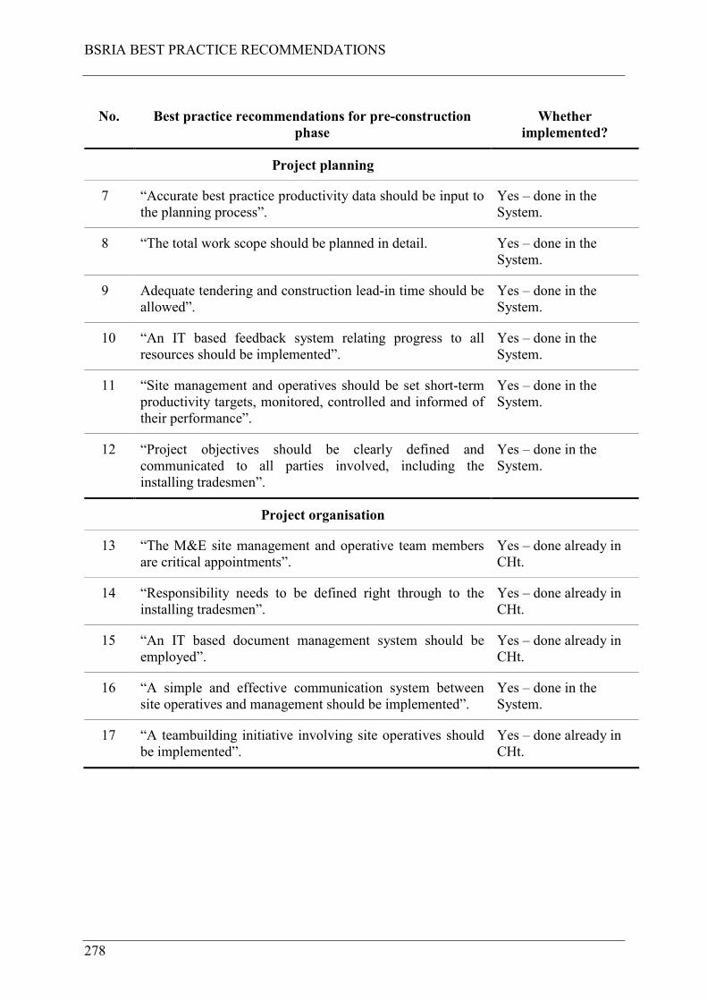
BSRIA BEST PRACTICE RECOMMENDATIONS
278
No. Best practice recommendations for pre-construction
phase
Whether
implemented?
Project planning
7 “Accurate best practice productivity data should be input to
the planning process”.
Yes – done in the
System.
8 “The total work scope should be planned in detail. Yes – done in the
System.
9 Adequate tendering and construction lead-in time should be
allowed”.
Yes – done in the
System.
10 “An IT based feedback system relating progress to all
resources should be implemented”.
Yes – done in the
System.
11 “Site management and operatives should be set short-term
productivity targets, monitored, controlled and informed of
their performance”.
Yes – done in the
System.
12 “Project objectives should be clearly defined and
communicated to all parties involved, including the
installing tradesmen”.
Yes – done in the
System.
Project organisation
13 “The M&E site management and operative team members
are critical appointments”.
Yes – done already in
CHt.
14 “Responsibility needs to be defined right through to the
installing tradesmen”.
Yes – done already in
CHt.
15 “An IT based document management system should be
employed”.
Yes – done already in
CHt.
16 “A simple and effective communication system between
site operatives and management should be implemented”.
Yes – done in the
System.
17 “A teambuilding initiative involving site operatives should
be implemented”.
Yes – done already in
CHt.
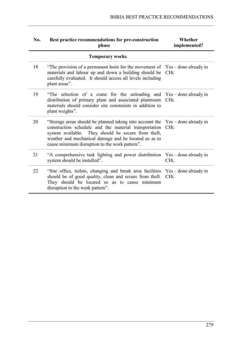
BSRIA BEST PRACTICE RECOMMENDATIONS
279
No. Best practice recommendations for pre-construction
phase
Whether
implemented?
Temporary works
18 “The provision of a permanent hoist for the movement of
materials and labour up and down a building should be
carefully evaluated. It should access all levels including
plant areas”.
Yes – done already in
CHt.
19 “The selection of a crane for the unloading and
distribution of primary plant and associated plantroom
materials should consider site constraints in addition to
plant weights”.
Yes – done already in
CHt.
20 “Storage areas should be planned taking into account the
construction schedule and the material transportation
system available. They should be secure from theft,
weather and mechanical damage and be located so as to
cause minimum disruption to the work pattern”.
Yes – done already in
CHt.
21 “A comprehensive task lighting and power distribution
system should be installed”.
Yes – done already in
CHt.
22 “Site office, toilets, changing and break area facilities
should be of good quality, clean and secure from theft.
They should be located so as to cause minimum
disruption to the work pattern”.
Yes – done already in
CHt.
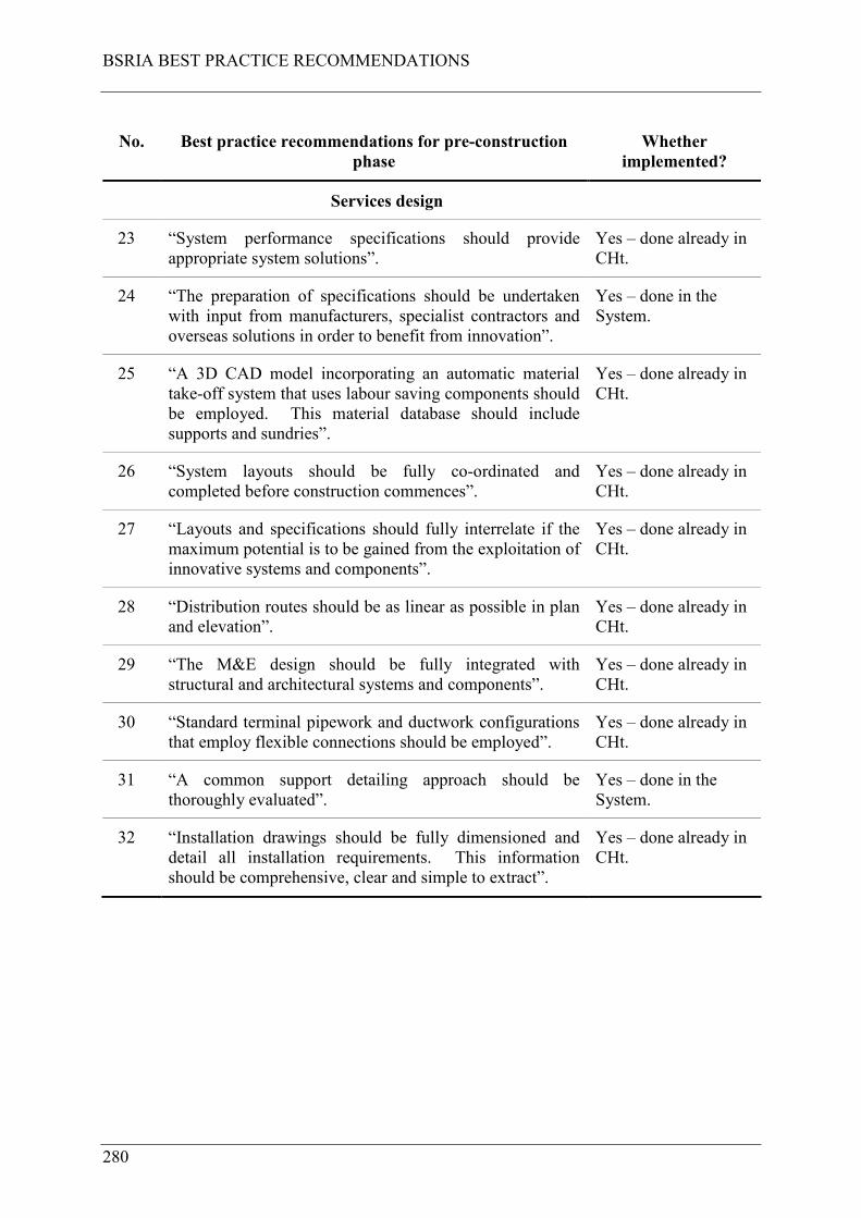
BSRIA BEST PRACTICE RECOMMENDATIONS
280
No. Best practice recommendations for pre-construction
phase
Whether
implemented?
Services design
23 “System performance specifications should provide
appropriate system solutions”.
Yes – done already in
CHt.
24 “The preparation of specifications should be undertaken
with input from manufacturers, specialist contractors and
overseas solutions in order to benefit from innovation”.
Yes – done in the
System.
25 “A 3D CAD model incorporating an automatic material
take-off system that uses labour saving components should
be employed. This material database should include
supports and sundries”.
Yes – done already in
CHt.
26 “System layouts should be fully co-ordinated and
completed before construction commences”.
Yes – done already in
CHt.
27 “Layouts and specifications should fully interrelate if the
maximum potential is to be gained from the exploitation of
innovative systems and components”.
Yes – done already in
CHt.
28 “Distribution routes should be as linear as possible in plan
and elevation”.
Yes – done already in
CHt.
29 “The M&E design should be fully integrated with
structural and architectural systems and components”.
Yes – done already in
CHt.
30 “Standard terminal pipework and ductwork configurations
that employ flexible connections should be employed”.
Yes – done already in
CHt.
31 “A common support detailing approach should be
thoroughly evaluated”.
Yes – done in the
System.
32 “Installation drawings should be fully dimensioned and
detail all installation requirements. This information
should be comprehensive, clear and simple to extract”.
Yes – done already in
CHt.

BSRIA BEST PRACTICE RECOMMENDATIONS
281
No. Best practice recommendations for pre-construction
phase
Whether
implemented?
Construction philosophy
33 “A comprehensive constructability review that involves
specialist M&E contractors should promote operation
efficiency and good access”.
Yes – done in the
System.
34 “The designs and specifications presented to site operatives
should promote the minimisation of site activities”.
Yes – done in the
System.
35 “Prefabrication and pre-assembly should be considered”. Yes – done already in
CHt.
36 “Standard time saving components and connections should
be used”.
Yes – done already in
CHt.
37 “The quality of types and sizes should be rationalised”. Yes – done in the
System.
Procurement strategy
38 “Timely supply of specified materials should be ensured”. Yes – done in the
System.
39 “An IT based material ordering and tracking system should
be employed”.
Partially done in the
System.
40 “Materials should be identified, sorted and grouped at the
point of manufacture and then delivered in a manner that
will aid efficient distribution on site”.
Yes – done in the
System.
41 “Sundries such as nuts, bolts, washers, gaskets, hangers,
threaded rod, unistrut, rivets, hemp/PTFE, and boss white
should always be available”.
Yes – done in the
System.
42 “A designated team should be responsible for planning and
moving material deliveries to their points of storage and
use”.
Yes – done in the
System.
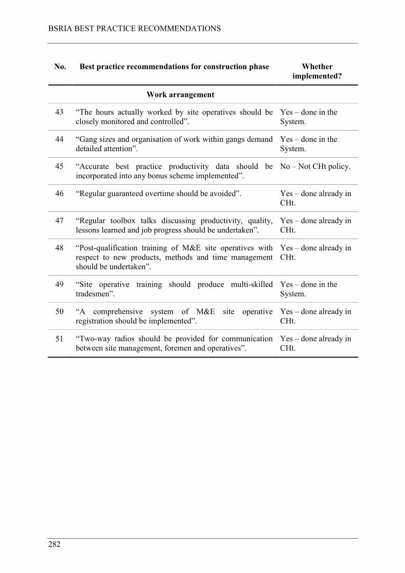
BSRIA BEST PRACTICE RECOMMENDATIONS
282
No. Best practice recommendations for construction phase Whether
implemented?
Work arrangement
43 “The hours actually worked by site operatives should be
closely monitored and controlled”.
Yes – done in the
System.
44 “Gang sizes and organisation of work within gangs demand
detailed attention”.
Yes – done in the
System.
45 “Accurate best practice productivity data should be
incorporated into any bonus scheme implemented”.
No – Not CHt policy.
46 “Regular guaranteed overtime should be avoided”. Yes – done already in
CHt.
47 “Regular toolbox talks discussing productivity, quality,
lessons learned and job progress should be undertaken”.
Yes – done already in
CHt.
48 “Post-qualification training of M&E site operatives with
respect to new products, methods and time management
should be undertaken”.
Yes – done already in
CHt.
49 “Site operative training should produce multi-skilled
tradesmen”.
Yes – done in the
System.
50 “A comprehensive system of M&E site operative
registration should be implemented”.
Yes – done already in
CHt.
51 “Two-way radios should be provided for communication
between site management, foremen and operatives”.
Yes – done already in
CHt.

BSRIA BEST PRACTICE RECOMMENDATIONS
283
No. Best practice recommendations for construction phase Whether
implemented?
Work area control
52 “Material should be delivered in an orderly manner to the
point of use by a designated unskilled crew. It should be
only handled once, be clearly identifiable and have
installation information attached”.
Yes – done in the
System.
53 “Material should be palletised or stored on mobile racks
with appropriate mechanical and weather protection. Any
surplus should be removed as soon as it is no longer
required”.
Yes – done in the
System.
54 “Sundries and small fittings should be stored at the
workface”.
Yes – done in the
System.
55 “A logical sequence of single trade visits to a designated
work area is imperative”.
Yes – done in the
System.
56 “A task should be completed in one visit to a specified
workplace”.
Yes – done in the
System.
57 “There should be designated rubbish collection points and
each tradesman should be encouraged to keep the
workplace tidy”.
Yes – done already in
CHt.
Installation
58 “Datum’s and grids should be agreed between all trades
before work commences”.
Yes – done in the
System.
59 “Working platforms should be available at all times”. Yes – done in the
System.
60 “Contractor lifts should be employed for positioning”. Yes – done already in
CHt.
61 “Power tools and in particular portable power tools for
cutting and fixing should be used at all times”.
Yes – done in the
System.
62 “Workbenches should be provided”. Yes – done in the
System.
63 “Appropriate functional overalls and tool belts should be
used”.
Yes – done in the
System.

BSRIA BEST PRACTICE RECOMMENDATIONS
284
Of the 63 recommendations one was not implemented (not CHt policy); two were partially
implemented (of which one was done anyway within CHt and one was done because of this
research project) and 60 were implemented in the System (of which 29 were done already
within CHt and 31 were implemented because of this research project).

SAFETY RESULTS FROM THE SAMPLE PERIOD
285
APPENDIX G SAFETY RESULTS FROM THE SAMPLE
PERIOD
Included here are the 19 minor injuries as reported in CHt’s accident reporting system for the
case study project. These are presented in table 6.2.

SAFETY RESULTS FROM THE SAMPLE PERIOD
286
Table 6.2 Safety results from the sample period
Accident
No.
Accident
Type
Date of
Accident
Assign
Primary
Cause
Summary Details of Accident Underlying
Causations
Behaviours Injured Body
Parts & Injury
Type
1 Minor
Injury
09-Aug-07 Slip/Trip On Level 3 CZ8 the operative put his foot in a hole for a
shower gulley that was unprotected. The hole was 150mm
diameter and had been protected. The reason why the
protection was removed was uncertain however in other
areas other hole protection had been removed to allow the
knocking out of the plastic pipe sleeves and likewise not
re-fixed adequately as original method of fixing was nails
when slab being cast. The nails were left in the hole and
the nail penetrated the top of the boot and injured top of
foot.
Miscellaneous /
Other
Human Error Right Foot|Other
2 Minor
Injury
05-Dec-07 Handling,
Lifting or
Carrying
Lifting on new equipment, pin not in fully and trapped
finger.
Inadequate
Training
Communication
Failure
Right
Fingers|Superficial
Cuts/Abrasions
3 Minor
Injury
11-Dec-07 Slip/Trip Installing drainage pipework and removed hole protection
over 150mm hole and later stepped back on a nail in
plywood which was left on floor by the injured person.
Miscellaneous /
Other
Human Error Left
Foot|Superficial
Cuts/Abrasions
4 Minor
Injury
13-Mar-08 Handling,
Lifting or
Carrying
Within the site compound a small portable generator was
left in the roadway. Richard moved the generator to allow
a van to pass and when setting the generator down trapped
his left hand wedding finger under the machine trapping
the finger nail. He attended hospital. Separation of nail
apparent.
Miscellaneous /
Other
Human Error Left Fingers|Other
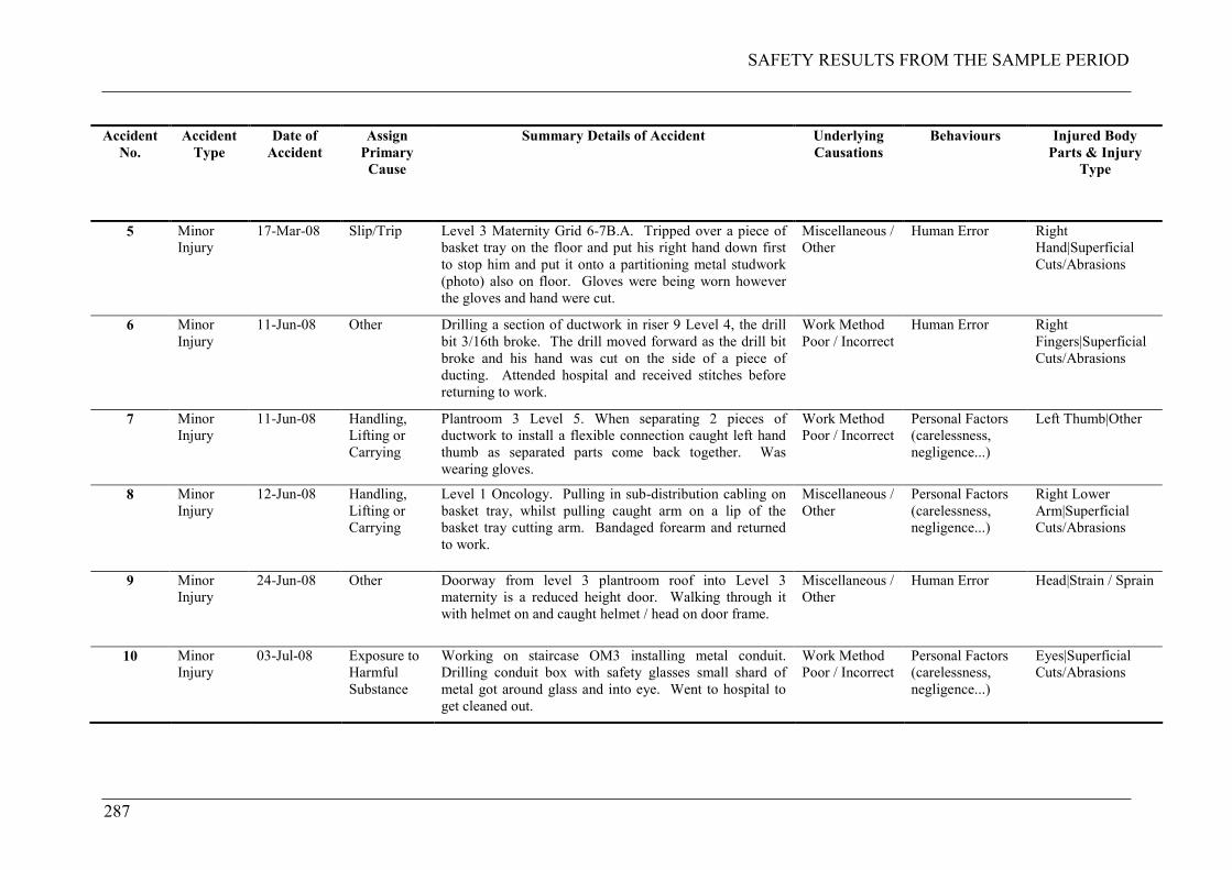
SAFETY RESULTS FROM THE SAMPLE PERIOD
287
Accident
No.
Accident
Type
Date of
Accident
Assign
Primary
Cause
Summary Details of Accident Underlying
Causations
Behaviours Injured Body
Parts & Injury
Type
5 Minor
Injury
17-Mar-08 Slip/Trip Level 3 Maternity Grid 6-7B.A. Tripped over a piece of
basket tray on the floor and put his right hand down first
to stop him and put it onto a partitioning metal studwork
(photo) also on floor. Gloves were being worn however
the gloves and hand were cut.
Miscellaneous /
Other
Human Error Right
Hand|Superficial
Cuts/Abrasions
6 Minor
Injury
11-Jun-08 Other Drilling a section of ductwork in riser 9 Level 4, the drill
bit 3/16th broke. The drill moved forward as the drill bit
broke and his hand was cut on the side of a piece of
ducting. Attended hospital and received stitches before
returning to work.
Work Method
Poor / Incorrect
Human Error Right
Fingers|Superficial
Cuts/Abrasions
7 Minor
Injury
11-Jun-08 Handling,
Lifting or
Carrying
Plantroom 3 Level 5. When separating 2 pieces of
ductwork to install a flexible connection caught left hand
thumb as separated parts come back together. Was
wearing gloves.
Work Method
Poor / Incorrect
Personal Factors
(carelessness,
negligence...)
Left Thumb|Other
8 Minor
Injury
12-Jun-08 Handling,
Lifting or
Carrying
Level 1 Oncology. Pulling in sub-distribution cabling on
basket tray, whilst pulling caught arm on a lip of the
basket tray cutting arm. Bandaged forearm and returned
to work.
Miscellaneous /
Other
Personal Factors
(carelessness,
negligence...)
Right Lower
Arm|Superficial
Cuts/Abrasions
9 Minor
Injury
24-Jun-08 Other Doorway from level 3 plantroom roof into Level 3
maternity is a reduced height door. Walking through it
with helmet on and caught helmet / head on door frame.
Miscellaneous /
Other
Human Error Head|Strain / Sprain
10 Minor
Injury
03-Jul-08 Exposure to
Harmful
Substance
Working on staircase OM3 installing metal conduit.
Drilling conduit box with safety glasses small shard of
metal got around glass and into eye. Went to hospital to
get cleaned out.
Work Method
Poor / Incorrect
Personal Factors
(carelessness,
negligence...)
Eyes|Superficial
Cuts/Abrasions
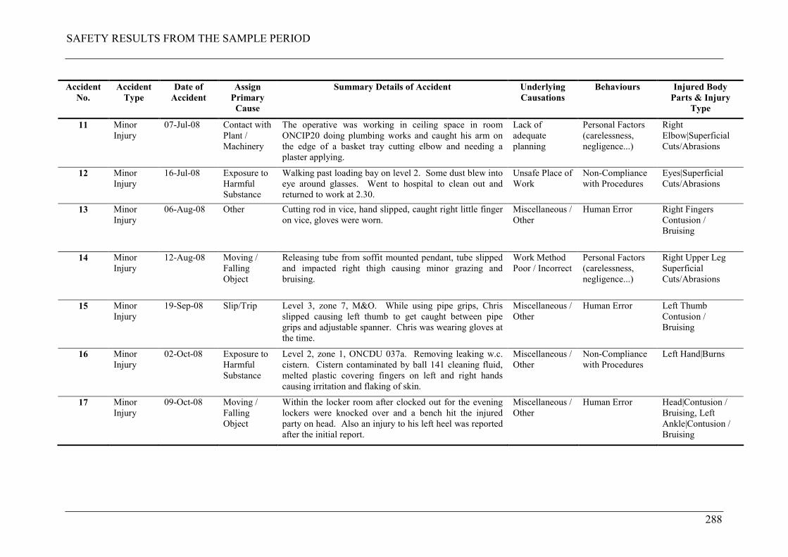
SAFETY RESULTS FROM THE SAMPLE PERIOD
288
Accident
No.
Accident
Type
Date of
Accident
Assign
Primary
Cause
Summary Details of Accident Underlying
Causations
Behaviours Injured Body
Parts & Injury
Type
11 Minor
Injury
07-Jul-08 Contact with
Plant /
Machinery
The operative was working in ceiling space in room
ONCIP20 doing plumbing works and caught his arm on
the edge of a basket tray cutting elbow and needing a
plaster applying.
Lack of
adequate
planning
Personal Factors
(carelessness,
negligence...)
Right
Elbow|Superficial
Cuts/Abrasions
12 Minor
Injury
16-Jul-08 Exposure to
Harmful
Substance
Walking past loading bay on level 2. Some dust blew into
eye around glasses. Went to hospital to clean out and
returned to work at 2.30.
Unsafe Place of
Work
Non-Compliance
with Procedures
Eyes|Superficial
Cuts/Abrasions
13 Minor
Injury
06-Aug-08 Other Cutting rod in vice, hand slipped, caught right little finger
on vice, gloves were worn.
Miscellaneous /
Other
Human Error Right Fingers
Contusion /
Bruising
14 Minor
Injury
12-Aug-08 Moving /
Falling
Object
Releasing tube from soffit mounted pendant, tube slipped
and impacted right thigh causing minor grazing and
bruising.
Work Method
Poor / Incorrect
Personal Factors
(carelessness,
negligence...)
Right Upper Leg
Superficial
Cuts/Abrasions
15 Minor
Injury
19-Sep-08 Slip/Trip Level 3, zone 7, M&O. While using pipe grips, Chris
slipped causing left thumb to get caught between pipe
grips and adjustable spanner. Chris was wearing gloves at
the time.
Miscellaneous /
Other
Human Error Left Thumb
Contusion /
Bruising
16 Minor
Injury
02-Oct-08 Exposure to
Harmful
Substance
Level 2, zone 1, ONCDU 037a. Removing leaking w.c.
cistern. Cistern contaminated by ball 141 cleaning fluid,
melted plastic covering fingers on left and right hands
causing irritation and flaking of skin.
Miscellaneous /
Other
Non-Compliance
with Procedures
Left Hand|Burns
17 Minor
Injury
09-Oct-08 Moving /
Falling
Object
Within the locker room after clocked out for the evening
lockers were knocked over and a bench hit the injured
party on head. Also an injury to his left heel was reported
after the initial report.
Miscellaneous /
Other
Human Error Head|Contusion /
Bruising, Left
Ankle|Contusion /
Bruising
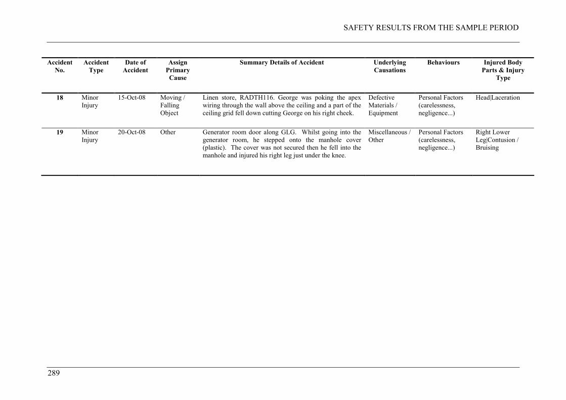
SAFETY RESULTS FROM THE SAMPLE PERIOD
289
Accident
No.
Accident
Type
Date of
Accident
Assign
Primary
Cause
Summary Details of Accident Underlying
Causations
Behaviours Injured Body
Parts & Injury
Type
18 Minor
Injury
15-Oct-08 Moving /
Falling
Object
Linen store, RADTH116. George was poking the apex
wiring through the wall above the ceiling and a part of the
ceiling grid fell down cutting George on his right cheek.
Defective
Materials /
Equipment
Personal Factors
(carelessness,
negligence...)
Head|Laceration
19 Minor
Injury
20-Oct-08 Other Generator room door along GLG. Whilst going into the
generator room, he stepped onto the manhole cover
(plastic). The cover was not secured then he fell into the
manhole and injured his right leg just under the knee.
Miscellaneous /
Other
Personal Factors
(carelessness,
negligence...)
Right Lower
Leg|Contusion /
Bruising

SAFETY RESULTS FROM THE SAMPLE PERIOD
290
LESSONS LEARNED FROM IMPLEMENTATION
291
APPENDIX H LESSONS LEARNED FROM
IMPLEMENTATION
Included here are certain important lessons learned for each of the main elements of the
System on the Maternity and Oncology phase together with the change implemented.
H.1 PLANNING AND PRODUCTION CONTROL
Last Planner System was only implemented during the installation phase of the case study
project. The problem found was that the team needed more visibility and reliability of the
preceding steps i.e. manufacturing, procurement, production drawings and design. On
following phases of the overall project LPS was implemented in each of these key steps.
H.2 POSTPONEMENT AND PARTS KITTING
As has been described in this thesis, type B and C components were to be parts kitted for
delivery direct to point of use on a call-off basis. For certain components (cast iron drainage
pipe and fittings) with low variety (small amount of component type per kit) parts ran out.
This was because of errors in either parts kitting or call-offs. The solution to this was too
kanban these components using a simple two bin system. When one bin was near to being
emptied it was simply replenished therefore avoiding shortages. This is presented in figure
6.1.
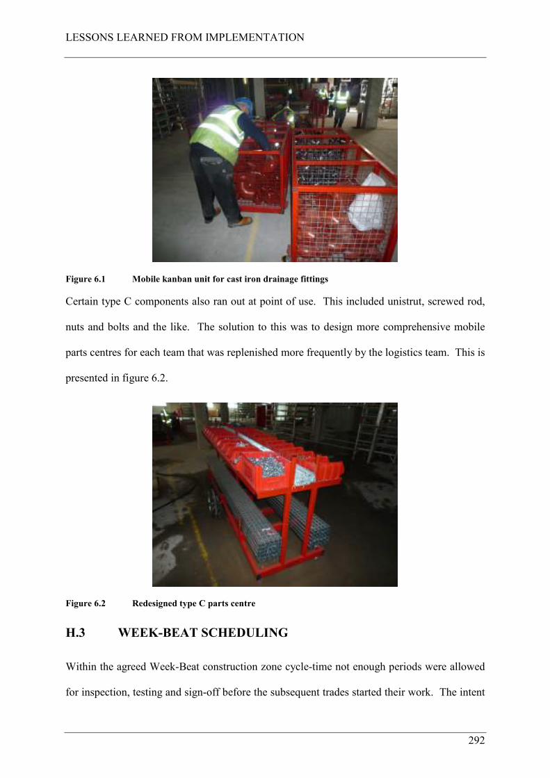
LESSONS LEARNED FROM IMPLEMENTATION
292
Figure 6.1 Mobile kanban unit for cast iron drainage fittings
Certain type C components also ran out at point of use. This included unistrut, screwed rod,
nuts and bolts and the like. The solution to this was to design more comprehensive mobile
parts centres for each team that was replenished more frequently by the logistics team. This is
presented in figure 6.2.
Figure 6.2 Redesigned type C parts centre
H.3 WEEK-BEAT SCHEDULING
Within the agreed Week-Beat construction zone cycle-time not enough periods were allowed
for inspection, testing and sign-off before the subsequent trades started their work. The intent

LESSONS LEARNED FROM IMPLEMENTATION
293
was to reduce overall cycle-time but this proved to be too tight in practice as it caused too
much working backlog building up to be done later. It also delayed insulation of pipework
systems which had to be done out of sequence. The solution to this was to add time back into
the Week-Beat sequence for testing (one week – line 12) and inspection and sign-off (one
week – line 15). This is presented in figure 6.3 for Hub and Wards MEP1 operations.
Hub Wards & DTC>
Drawn by: Dwg No. Revision No. Notes:
Project Ref. C:\Program Files\Asta\Asta Powerproject\Projects\Projects\Hub and Wards\DHW Working Prog R3a 09_04_22.pp Planned by Asta Powerproject
Line Name Dur-2 -1 1 2 3 4 5 6 7 8 9-3
1
2
3
4
5
6
7
8
9
10
11
12
13
14
15
BFP 1
Fit partition head track Corridor & rooms
Court yard RWO's
MEP 1
RWP/SVP's pipework and outlets incl. test
Riser modules
Corridor modules
Ductwork main runs through rooms
Ductwork branches & components
Distribution run outs (M) from corridormodulesDistribution run outs (E) from corridormodules
Pressure test pipework and ductwork
Pneumatic tube
Insulate pipework and ductwork
MEP 1 sign off prior to BFP 2 Snag & clear
1w
1w
1w
8w
1w
1w
1w
1w
1w
1w
1w
1w
1w
1w
1w
1
2
3
4
5
6
7
8
9
10
11
12
13
14
15
Processes
BFP1 MEP1
Progress Periods
wk96
Figure 6.3 Revised MEP1 operations programme for Hub and Wards
Also close-scheduling of different trades would not work on operations carried out in the
same construction zone in the same week. This was considered to be too tight and relied too
much on the exact synchronisation of different work by different teams. Plus too many sets
of workers with their mobile work cells occupied the space. The solution to this was not to
close schedule operations within a Week-Beat period.
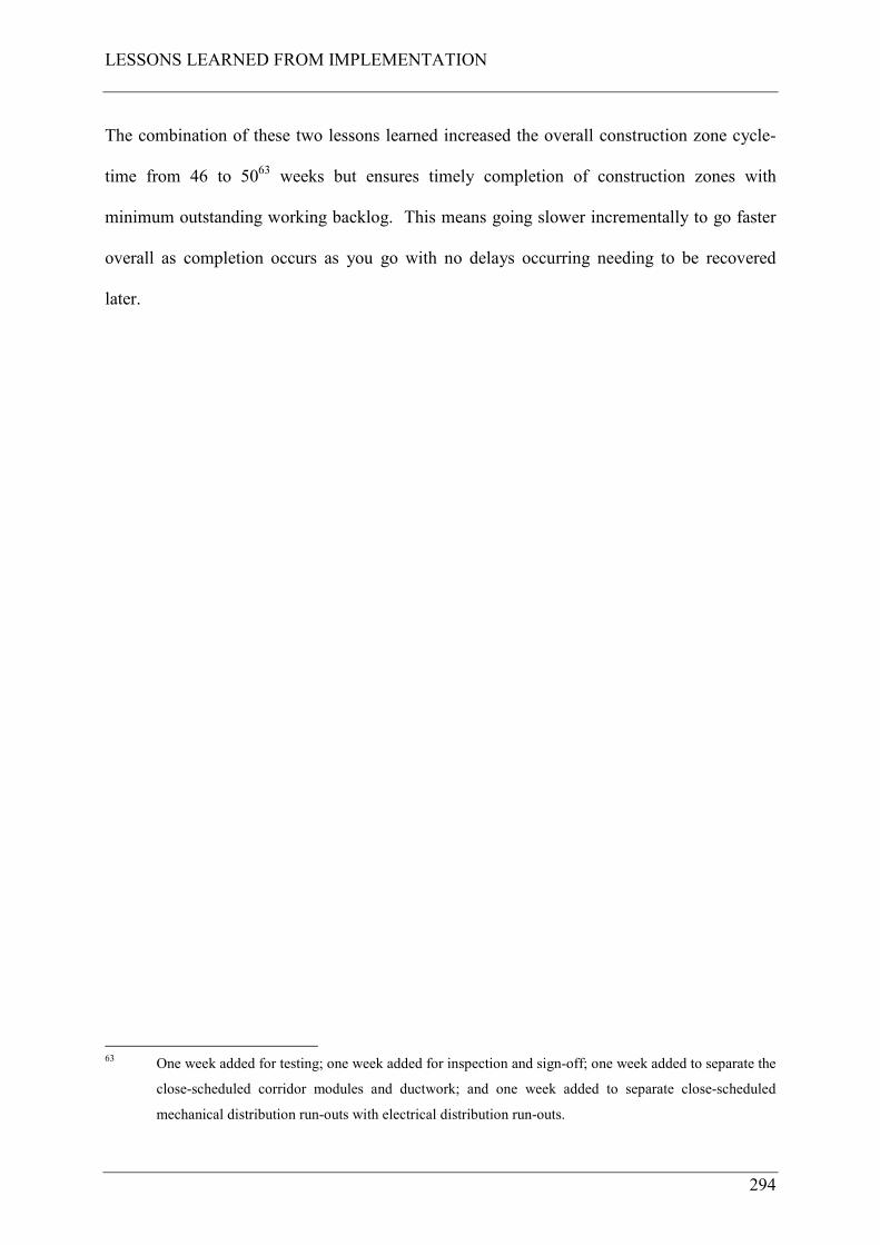
LESSONS LEARNED FROM IMPLEMENTATION
294
The combination of these two lessons learned increased the overall construction zone cycle-
time from 46 to 5063 weeks but ensures timely completion of construction zones with
minimum outstanding working backlog. This means going slower incrementally to go faster
overall as completion occurs as you go with no delays occurring needing to be recovered
later.
63 One week added for testing; one week added for inspection and sign-off; one week added to separate the
close-scheduled corridor modules and ductwork; and one week added to separate close-scheduled
mechanical distribution run-outs with electrical distribution run-outs.