transforming tomorrow
TRANSCRIPT

INDUSTRIAL CONTROL TRANSFORMERS
MANUFACTURING CO., INC.
Transformingtomorrow.

2

Industrial Control Transformers ................4
Product Features .................................................5
Selection Process ............................................... 6
Voltage Groups ..................................................... 8
Fusing Accessories ............................................18
Fusing Sizing Chart ........................................ 20
Connecting Diagrams ...................................22
MANUFACTURING CO., INC.
Table of Contents

4
Industrial Control Transformers
SNC’s Industrial Control Transformers are specially designed to accommodate the
momentary current inrush caused when electromagnetic components are energized.
These transformers deliver excellent secondary voltage requirements and meet or
exceed the standards established by UL and cUL. Their rugged construction and quality
electrical characteristics ensure reliable operation of electromagnetic devices and
trouble-free performance.
PRODUCT FEATURES
MANUFACTURING CO., INC.
FINGER-SAFE TERMINALSTerminals are molded into the transformer
for extra durability and are finger safe. The deep terminal channels help prevent
short circuits from stray wires.
MOUNTING ADAPTOR FOR FUSE BLOCKSIncluded on all transformers
up to 3kVA.
PRODUCT LABELAll SNC control power transformers
come labeled with power specifications, agency listings and manufacturing date codes.
FLEXIBLE MOUNTINGHeavy gauge steel mounting foot ensures
a secure installation. Slotted holes allow for flexible mounting locations.
QUALITY MATERIALSHigh-grade silicon steel laminations and fine quality copper magnet wire reduce core losses and ensure high efficiency.
WIRING DIAGRAMAll SNC control power
transformers come with
wiring diagrams for ease of installation.
ENVIRONMENTAL PROTECTION
Rugged construction with fully encapsulated windings protect
the transformer from harsh
environments for a long life.

Product FeaturesEnclosed coils (50 - 5kVA). Completely encloses the transformer coils
to protect against moisture, dirt, dust and industrial contaminants for
maximum protection in industrial environments.
Finger-safe terminals integrally built in. Up to 30% greater terminal
contact area permits low-loss connections. Extra deep barriers reduce
the chance of shorts from frayed leads or careless wiring. Pressure plate
terminals designed to accept bare wire, ferrules, spade or ring lugs.
Attractive black matte finish and easy to read label with complete wiring diagram.
Terminals are molded into the transformer for a robust, compact
design. A full quarter inch of thread on the terminal screws prevents
stripping and pullout.
Mounting plate is heavy gauge steel to add strength to core
construction and provide stability. Slotted mounting feet permit
easy and flexible installation.
Two parallel jumper links come standard with transformers when
required so they can be wired for dual primary voltages.
Class 130°C (226°F) insulation system with 55°C (131°F)
temperature rise on 50 - 100VA.
Class 130°C (226°F) insulation system with 80°C (176°F)
temperature rise on 150 - 750VA.
Class 180°C (356°F) insulation system with 115°C (239°F)
temperature rise on 1000 - 5000VA.
UL, cUL listed, CSA certified. CE listing available upon request.
PRODUCT FEATURES | INDUSTRIAL CONTROL TRANSFORMERS 5

6
Transformer Selection ProcessSelecting a transformer for industrial control circuit applications requires knowledge of the following terms:
Inrush VA is the product of load voltage
(V) multiplied by the current (A) that
is required during circuit start-up. It is
calculated by adding the in-rush VA
requirements of all devices (contactors,
timers, relays, pilot lights, solenoids, etc.),
which will be energized together. Inrush
VA requirements are best obtained from
the component manufacturer.
Sealed VA is the product of load voltage
(V) multiplied by the current (A) after
initial start-up or under normal operating
conditions. It is calculated by adding the
sealed VA requirements of all electrical
components that will be energized at
any given time. Sealed VA requirements
are best obtained from the component
manufactuer. Sealed VA is also referred
to as steady state VA.
Primary Voltage is the voltage available
from the electrical distribution system
and its operational frequency, which is
connected to the transformer supply
voltage terminals.
Secondary Voltage is the voltage
required for load operation which is
connected to the transformer load
voltage terminals.
SELECTION PROCESS
INRUSH REGULATION DATA CHARTINRUSH VA @ 0.4 POWER FACTOR
Continuous VA Transformer Nameplate Rating
85% Secondary Voltage
90% Secondary Voltage
95% Secondary Voltage
25 125 100 75
50 200 167 131
75 311 257 200
100 471 377 276
150 923 716 491
200 1125 883 622
250 1944 1476 970
300 2040 1547 1020
350 3300 2400 1400
500 3191 2500 1745
750 6025 4520 2915
1000 8100 5600 3000
1500 16000 12000 6600
2000 19500 13500 7300
3000 25500 18250 10500
5000 75000 56000 33000

SELECTION PROCESS | INDUSTRIAL CONTROL TRANSFORMERS 7
Determine the application inrush VA by using the
following industry accepted formula:
Application Inrush VA = √((Inrush VA)² r (Sealed VA)²)
Refer to the Regulation Data Chart. If the primary
voltage is basically stable and does not vary by more
than 5% from nominal, the 90% secondary voltage
column should be used. If the primary voltage varies
between 5% and 10% of nominal, the 95% secondary
voltage column should be used.
After determining the proper secondary voltage
column, read down until a value equal to or greater
than the application inrush VA is found. In no case
should a figure less than the application inrush VA be used.
Read left to the Transformer VA Rating column to
determine the proper transformer for this application.
As a final check, make sure that the Transformer VA Rating is equal to or greater than the total sealed
requirements. If not, select a transformer with a VA
rating equal to or greater than the total sealed VA.
Refer to the following pages to determine the proper
catalog number based on the transformer VA, and
primary and secondary voltage requirements.
1
2
3
4
5
Once the circuit variables
have been determined, transformer
selection is a simple 5-step process.

Group Primary Secondary VA Sizes View Detals on Page
A 220 x 440, 230 x 460, 240 x 480 110, 115, 120 50 - 5000 9
B 240 x 480 24 50 - 750 9
C 120 x 240 24 50 - 750 10
D 115 x 230 24 50 - 500 10
E 550, 575, 600 110, 115, 120 50 - 750 11
F 208/277 120 50 - 750 11
G 200/220/440, 208/230/460, 240/480 110, 115, 120 50 - 3000 12
H 230/460/575 95/115 150 - 5000 13
I 380/400/415 110/220 50 - 5000 13
J 200/208, 220/230/240, 440/460/480 23 x 110, 24 x 115, 25 x 120 50 - 500 14
K 240 x 480 120 x 240 50 - 3000 15
L240/230/220/208, 416/400/380, 480/460/440, 600/575/550/500
130/125/120/110, 120/115/110/100, 99/95/91/85 50 - 750 15
M220 x 440, 230 x 460,
240 x 480110 x 120, 115 x 230,
120 x 240 1000 - 5000 16
N 240/347/380 120 x 240 1000 - 5000 16
S 600 24 50 - 500 17
T 208/277 24 50 - 750 17
VOLTAGE TABLE
VOLTAGE GROUPS
SNC Voltage GroupsSNC Industrial Control Transformers are available in a wide variety of primary and secondary
voltages, many displayed below. If you do not see the voltages required for your application,
contact us about a customized option.
8
Image is a general representation of a typical SNC Control Transformer without fusing accessories or jumper links. Transformers 50VA - 350VA have 4 terminals per side, and units 500VA and higher have 6 terminals per side.
Top view Side view

VOLTAGE CHARTS | INDUSTRIAL CONTROL TRANSFORMERS 9
VOLTAGE GROUP A220 x 440, 230 x 460, 240 x 480 PRIMARY VOLTS 110, 115, 120 SECONDARY VOLTS 50/60 Hz
Approximate Dimensions and Weight
VA Rating
Part #Max.
Depth (A)Max.
Width (B)Max.
Height (C)Mounting Depth (D)
Mounting Width (E)
Mounting Hole Shipping Weight (lbs.)Depth Width
50 P22585 3.32 3.00 2.79 2.00 2.50 0.20 0.41 2.6
75 P22426 3.82 3.00 2.79 2.50 2.50 0.20 0.41 3.5
100 P22427 3.78 3.38 3.10 2.38 2.81 0.20 0.41 4.2
150 P22428 4.27 3.75 3.41 2.88 3.13 0.20 0.41 6.7
200 P22645 4.05 4.50 4.04 2.50 3.75 0.20 0.41 8.5
250 P22429 4.55 4.50 4.04 2.88 3.75 0.20 0.41 10.0
300 P22646 4.55 4.50 4.04 3.25 3.75 0.20 0.41 11.3
350 P22430 5.28 4.50 4.04 3.75 3.75 0.20 0.41 13.6
500 P22431 5.75 5.25 4.66 4.25 4.38 0.31 1.06 15.8
750 P22432 7.00 5.25 4.66 5.38 4.38 0.31 1.06 28.1
1000 P22433 6.61 7.00 5.65 4.00 6.13 0.31 1.06 29.8
1500 P22434 7.62 7.00 5.65 4.50 6.13 0.31 1.06 30.0
2000 P22435 8.37 7.00 5.65 5.13 6.13 0.31 1.06 38.0
3000 P22436 7.82 9.00 7.62 4.25 6.50 0.44 1.00 53.0
5000 P22437 9.06 9.00 7.62 7.25 7.50 0.44 1.00 89.0
VOLTAGE GROUP B240 x 480 PRIMARY VOLTS 24 SECONDARY VOLTS 50/60 Hz
Approximate Dimensions and Weight
VA Rating
Part #Max.
Depth (A)Max.
Width (B)Max.
Height (C)Mounting Depth (D)
Mounting Width (E)
Mounting Hole Shipping Weight (lbs.)Depth Width
50 P23493 3.32 3.00 2.79 2.00 2.50 0.20 0.41 2.6
75 P23494 3.82 3.00 2.79 2.50 2.50 0.20 0.41 3.5
100 P23495 3.78 3.38 3.11 2.38 2.81 0.20 0.41 4.2
150 P23496 4.27 3.75 3.42 2.88 3.13 0.20 0.41 6.7
250 P23497 4.55 4.50 4.04 2.88 3.75 0.20 0.41 10.0
350 P23498 5.28 4.50 4.04 3.75 3.75 0.20 0.41 13.6
500 P23499 5.75 5.25 4.66 4.25 4.38 0.31 1.06 15.8
750 P23500 7.00 5.25 4.66 5.38 4.38 0.31 1.06 28.1

10
VOLTAGE GROUP C120 x 240 PRIMARY VOLTS 24 SECONDARY VOLTS 50/60 Hz
Approximate Dimensions and Weight
VA Rating
Part #Max.
Depth (A)Max.
Width (B)Max.
Height (C)Mounting Depth (D)
Mounting Width (E)
Mounting Hole Shipping Weight (lbs.)Depth Width
50 P23485 3.32 3.00 2.79 2.00 2.50 0.20 0.41 2.6
75 P23486 3.82 3.00 2.79 2.50 2.50 0.20 0.41 3.5
100 P23487 3.78 3.38 3.11 2.38 2.81 0.20 0.41 4.2
150 P23488 4.27 3.75 3.42 2.88 3.13 0.20 0.41 6.7
250 P23489 4.55 4.50 4.04 2.88 3.75 0.20 0.41 10.0
350 P23490 5.28 4.50 4.04 3.75 3.75 0.20 0.41 13.6
500 P23491 5.75 5.25 4.66 4.25 4.38 0.31 1.06 15.8
750 P23492 7.00 5.25 4.66 5.38 4.38 0.31 1.06 28.1
VOLTAGE GROUP D115 x 230 PRIMARY VOLTS 24 SECONDARY VOLTS 50/60 Hz
Approximate Dimensions and Weight
VA Rating
Part #Max.
Depth (A)Max.
Width (B)Max.
Height (C)Mounting Depth (D)
Mounting Width (E)
Mounting Hole Shipping Weight (lbs.)Depth Width
50 P24520 3.32 3.00 2.79 2.00 2.50 0.20 0.41 2.60
75 P24521 3.82 3.00 2.79 2.50 2.50 0.20 0.41 3.50
100 P24522 3.78 3.38 3.11 2.38 2.81 0.20 0.41 4.20
150 P24523 4.27 3.75 3.42 2.88 3.13 0.20 0.41 6.70
200 P24524 4.35 3.75 3.42 2.88 3.13 0.20 0.41 7.25
250 P24525 4.55 4.50 4.04 2.88 3.75 0.20 0.41 10.00
300 P24526 5.10 4.50 4.04 2.88 3.75 0.20 0.41 11.50
350 P24527 5.28 4.50 4.04 3.75 3.75 0.20 0.41 13.60
500 P24528 5.75 5.25 4.66 4.25 4.38 0.31 1.06 15.75

VOLTAGE GROUP E550, 575, 600 PRIMARY VOLTS 110, 115, 120 SECONDARY VOLTS 50/60 Hz
Approximate Dimensions and Weight
VA Rating
Part #Max.
Depth (A)Max.
Width (B)Max.
Height (C)Mounting Depth (D)
Mounting Width (E)
Mounting Hole Shipping Weight (lbs.)Depth Width
50 P22482 3.23 3.00 2.79 2.00 2.50 0.20 0.41 2.6
75 P22483 3.73 3.00 2.79 2.50 2.50 0.20 0.41 3.5
100 P22484 3.69 3.38 3.11 2.38 2.81 0.20 0.41 4.2
150 P22485 4.17 3.75 3.42 2.88 3.13 0.20 0.41 6.7
250 P22486 4.47 4.50 4.04 2.88 3.75 0.20 0.41 10.0
350 P22487 5.19 4.50 4.04 3.75 3.75 0.20 0.41 13.6
500 P22488 5.17 5.25 4.66 4.25 4.38 0.31 1.06 15.9
750 P22489 6.42 5.25 4.66 5.38 4.38 0.31 1.06 28.1
1000 P23767 6.21 7.00 5.65 4.00 6.13 0.31 1.06 29.8
VOLTAGE GROUP F208/277 PRIMARY VOLTS 120 SECONDARY VOLTS 50/60 Hz
Approximate Dimensions and Weight
VA Rating
Part #Max.
Depth (A)Max.
Width (B)Max.
Height (C)Mounting Depth (D)
Mounting Width (E)
Mounting Hole Shipping Weight (lbs.)Depth Width
50 P24454 3.23 3.00 2.79 2.00 2.50 0.20 0.41 2.6
75 P24455 3.73 3.00 2.79 2.50 2.50 0.20 0.41 3.5
100 P24456 3.69 3.38 3.11 2.38 2.81 0.20 0.41 4.2
150 P24457 4.17 3.75 3.42 2.88 3.13 0.20 0.41 6.7
250 P24458 4.47 4.50 4.04 2.88 3.75 0.20 0.41 10.0
350 P24459 5.19 4.50 4.04 3.75 3.75 0.20 0.41 13.6
500 P24460 5.17 5.25 4.66 4.25 4.38 0.31 1.06 15.8
750 P24461 6.42 5.25 4.66 5.38 4.38 0.31 1.06 28.1
Our custom transformers are helping power the U.S. Navy’s stealth destroyer, the Zumwalt.
VOLTAGE CHARTS | INDUSTRIAL CONTROL TRANSFORMERS 11

VOLTAGE GROUP G200/220/440, 208/230/460, 240/480 PRIMARY VOLTS 110, 115, 120 SECONDARY VOLTS 50/60 Hz
Approximate Dimensions and Weight
VA Rating
SNC Part #Max.
Depth (A)Max.
Width (B)Max.
Height (C)Mounting Depth (D)
Mounting Width (E)
Mounting Hole Shipping Weight (lbs.)Depth Width
50 P23613 3.23 3.00 2.79 2.00 2.50 0.20 0.41 2.6
75 P23614 3.73 3.00 2.79 2.50 2.50 0.20 0.41 3.5
100 P23615 3.69 3.38 3.11 2.38 2.81 0.20 0.41 4.2
150 P23616 4.17 3.75 3.42 2.88 3.13 0.20 0.41 6.7
200 P23617 3.96 4.50 4.04 2.88 3.75 0.20 0.41 8.5
250 P23618 4.47 4.50 4.04 3.25 3.75 0.20 0.41 10.0
300 P23619 4.47 4.50 4.04 3.25 3.75 0.20 0.41 11.3
350 P23620 5.19 4.50 4.04 3.75 3.75 0.20 0.41 13.6
500 P23621 5.17 5.25 4.66 4.75 4.38 0.31 1.06 16.0
750 P22612 6.42 5.25 4.66 5.38 4.38 0.31 1.06 28.1
1000 P22613 6.21 7.00 5.65 4.00 6.13 0.31 1.06 29.8
1500 P22614 7.23 7.00 5.65 4.50 6.13 0.31 1.06 30.0
2000 P22615 7.98 7.00 5.43 5.13 6.13 0.31 1.06 38.0
3000 P22617 7.50 9.00 7.62 4.25 6.50 0.44 1.00 53.0
5000 P22618 9.00 9.00 7.62 7.25 7.50 0.44 1.00 89.0
Automated manufacturing facilities around the world are using SNC’s transformers for their reliability to deliver innovation and increase their speed to market.
12

VOLTAGE GROUP H230/460/575 PRIMARY VOLTS 95/115 SECONDARY VOLTS 1Ø 50/60 Hz
Approximate Dimensions and Weight
VA Rating
Part #Max.
Depth (A)Max.
Width (B)Max.
Height (C)Mounting Depth (D)
Mounting Width (E)
Mounting Hole Shipping Weight (lbs.)Depth Width
50 P24544 3.23 3.00 2.79 2.00 2.50 0.20 0.41 2.6
75 P24545 3.73 3.00 2.79 2.50 2.50 0.20 0.41 3.5
100 P24546 3.69 3.38 3.11 2.38 2.81 0.20 0.41 4.2
150 P24547 4.17 3.75 3.42 2.88 3.13 0.20 0.41 6.7
250 P24548 4.47 4.50 4.04 3.25 3.75 0.20 0.41 10.0
350 P24549 5.19 4.50 4.04 3.75 3.75 0.20 0.41 13.6
500 P24550 5.17 5.25 4.66 4.75 4.38 0.31 1.06 16.0
750 P24551 6.42 5.25 4.66 5.38 4.38 0.31 1.06 28.1
1000 P24427 6.21 7.00 5.65 4.00 6.13 0.31 1.06 29.8
1500 P24428 7.98 7.00 5.43 5.13 6.13 0.31 1.06 38.0
2000 P24429 7.98 7.00 5.43 5.13 6.13 0.31 1.06 38.0
3000 P24430 9.00 9.00 7.62 7.25 7.50 0.44 1.00 89.0
5000 * P24431 10.00 9.00 8.73 8.25 7.50 0.44 1.00 101.0
VOLTAGE GROUP I 380/400/415 PRIMARY VOLTS: 110/220 SECONDARY VOLTS 50/60Hz
Approximate Dimensions and Weight
VA Rating
Part #Max.
Depth (A)Max.
Width (B)Max.
Height (C)Mounting Depth (D)
Mounting Width (E)
Mounting Hole Shipping Weight (lbs.)Depth Width
50 P24444 3.32 3.00 2.79 2.00 2.50 0.20 0.41 2.6
75 P24445 3.82 3.00 2.79 2.50 2.50 0.20 0.41 3.5
100 P24446 3.78 3.38 3.11 2.38 2.81 0.20 0.41 4.2
150 P24447 4.27 3.75 3.42 2.88 3.13 0.20 0.41 6.7
200 P24448 4.05 4.50 4.04 2.50 3.75 0.20 0.41 8.5
250 P24449 4.55 4.50 4.04 2.88 3.75 0.20 0.41 10.0
300 P24450 4.55 4.50 4.04 3.25 3.75 0.20 0.41 11.3
350 P24451 5.28 4.50 4.04 3.75 3.75 0.20 0.41 13.6
500 P24452 5.75 5.25 4.66 4.25 4.38 0.31 1.06 16.1
750 P24453 7.00 5.25 4.66 5.38 4.38 0.31 1.06 28.1
*GEN I Design
VOLTAGE CHARTS | INDUSTRIAL CONTROL TRANSFORMERS 13

14
VOLTAGE GROUP J200/208, 220/230/240, 440/460/480 PRIMARY VOLTS 23 x 110, 24 x 115, 25 x 120 SECONDARY VOLTS 50/60 Hz
Approximate Dimensions and Weight
VA Rating
Part #Max.
Depth (A)Max.
Width (B)Max.
Height (C)Mounting Depth (D)
Mounting Width (E)
Mounting Hole Shipping Weight (lbs.)Depth Width
45 TBA 3.73 3.00 2.79 2.50 2.50 0.20 0.41 3.5
50 P22475 3.73 3.00 2.79 2.50 2.50 0.20 0.41 3.5
75 P22476 3.69 3.38 3.11 2.38 2.81 0.20 0.41 4.2
100 P22477 4.17 3.75 3.42 2.88 3.13 0.20 0.41 6.7
150 P22478 4.17 3.75 3.42 2.88 3.13 0.20 0.41 6.7
200 P24812 4.47 4.50 4.04 2.88 3.75 0.20 0.41 10.0
250 P22479 5.19 4.50 4.04 3.75 3.75 0.20 0.41 13.6
300 TBA 5.19 4.50 4.04 3.75 3.75 0.20 0.41 13.6
350 P22480 5.17 5.25 4.66 4.25 4.38 0.31 1.06 16.2
500 P22481 6.42 5.25 4.66 5.38 4.38 0.31 1.06 28.1
750 P22473 7.23 7.00 5.65 4.00 6.13 0.31 1.06 30.0
1000 P23994 7.98 7.00 5.43 5.13 6.13 0.31 1.06 38.0
CUSTOM TRANSFORMERS
SNC builds a wide variety of custom transformers for
a broad range of industries to meet our customers’
individual application requirements.
To learn more, visit:
www.sncmfg.com/custom-transformers

VOLTAGE GROUP K240 x 480 PRIMARY VOLTS 120 x 240 SECONDARY VOLTS 50/60Hz
Approximate Dimensions and Weight
VA Rating
Part #Max.
Depth (A)Max.
Width (B)Max.
Height (C)Mounting Depth (D)
Mounting Width (E)
Mounting Hole Shipping Weight (lbs.)Depth Width
50 P23691 3.41 3.00 2.79 2.00 2.50 0.20 0.41 2.6
75 P23692 3.91 3.00 2.79 2.50 2.50 0.20 0.41 3.5
100 P23693 3.86 3.38 3.10 2.38 2.81 0.20 0.41 4.2
150 P23694 4.36 3.75 3.41 2.88 3.13 0.20 0.41 6.7
200 P23695 4.14 4.50 4.04 2.50 3.75 0.20 0.41 8.5
250 P23696 4.64 4.50 4.04 2.88 3.75 0.20 0.41 10.0
300 P23697 4.64 4.50 4.04 3.25 3.75 0.20 0.41 11.3
350 P23698 5.37 4.50 4.04 3.75 3.75 0.20 0.41 13.6
500 P23699 5.75 5.25 4.66 4.25 4.38 0.31 1.06 17.3
750 P23700 6.74 5.25 4.66 5.38 4.38 0.31 1.06 28.1
1000 P23701 7.01 7.00 5.65 5.38 4.38 0.31 1.06 29.8
1500 P23702 8.00 7.00 5.65 4.50 6.13 0.31 1.06 30.0
2000 P24215 8.76 7.00 5.65 5.13 6.13 0.31 1.06 38.0
3000 P23703 8.14 9.00 7.62 4.25 6.50 0.44 1.00 53.0
5000 P24216 9.14 9.00 7.62 7.25 7.50 0.44 1.00 89.0
VOLTAGE GROUP L240/230/220/208, 416/400/380, 480/460/440, 600/575/550/500 PRIMARY VOLTS 130/125/120/110, 120/115/110/100, 99/95/91/85 SECONDARY VOLTS 1Ø 50/60 Hz
Approximate Dimensions and Weight
VA Rating
Part #Max.
Depth (A)Max.
Width (B)Max.
Height (C)Mounting Depth (D)
Mounting Width (E)
Mounting Hole Shipping Weight (lbs.)Depth Width
50 P24432 4.44 3.00 3.45 2.38 2.81 0.20 0.41 4.2
100 P24433 4.90 3.75 4.01 2.88 3.13 0.20 0.41 6.7
150 P24434 4.58 4.50 4.64 2.88 3.75 0.20 0.41 10.0
250 P24435 5.08 4.50 4.64 3.75 3.75 0.20 0.41 13.6
350 P24436 6.42 5.25 4.66 4.25 4.38 0.31 1.06 28.1
500 P24437 7.75 5.25 4.67 6.13 4.38 0.31 1.06 28.1
750 P24438 6.21 6.38 5.65 4.00 6.13 0.31 1.06 29.8
VOLTAGE CHARTS | INDUSTRIAL CONTROL TRANSFORMERS 15

16
VOLTAGE GROUP N 240/387/380 PRIMARY VOLTS 120 x 240 SECONDARY VOLTS 50/60Hz
Approximate Dimensions and Weight
VA Rating
Part #Max.
Depth (A)Max.
Width (B)Max.
Height (C)Mounting Depth (D)
Mounting Width (E)
Mounting Hole Shipping Weight (lbs.)Depth Width
1000 P24462 6.23 7.00 5.65 4.00 6.13 0.31 1.06 29.8
1500 P24463 7.23 7.00 5.65 4.50 6.13 0.31 1.06 30.0
2000 P24464 7.98 7.00 5.65 5.13 6.13 0.31 1.06 38.0
3000 P24465 7.82 9.00 7.62 4.25 6.50 0.44 1.00 53.0
5000 P24466 8.81 9.00 7.62 7.25 7.50 0.44 1.00 89.0
Notes: · Jumper Link and Fuse Clip Ht not included
· Add 5/16" to the depth when fuse clips are included (50 thru 350VA)
· Add 1/2" to the height when fuse block is included (1, 2, and 3 poles) 500 thru 5000VA)
· Add 1 3/8" to the height when fuse block is included (1, 2, and 3 poles) (50 thru 350VA)
VOLTAGE GROUP M 220 x 440, 230 x 460, 240 x 480 PRIMARY VOLTS 110 x 120, 115 x 230, 120 x 240 SECONDARY VOLTS 1Ø 50/60 Hz
Approximate Dimensions and Weight
VA Rating
Part #Max.
Depth (A)Max.
Width (B)Max.
Height (C)Mounting Depth (D)
Mounting Width (E)
Mounting Hole Shipping Weight (lbs.)Depth Width
1000 P24439 7.01 7.00 5.65 5.38 4.38 0.31 1.06 29.8
1500 P24440 8.00 7.00 5.65 4.50 6.13 0.31 1.06 30.0
2000 P24441 8.76 7.00 5.65 5.13 6.13 0.31 1.06 38.0
3000 P24442 8.14 9.00 7.62 4.25 6.50 0.44 1.00 53.0
5000 P24443 9.14 9.00 7.62 7.25 7.50 0.44 1.00 89.0

VOLTAGE GROUP T 208/277 PRIMARY VOLTS 24 SECONDARY VOLTS 50/60 Hz
Approximate Dimensions and Weight
VA Rating
Part #Max.
Depth (A)Max.
Width (B)Max.
Height (C)Mounting Depth (D)
Mounting Width (E)
Mounting Hole Shipping Weight (lbs.)Depth Width
50 TBD 3.23 3.00 2.79 2.00 2.50 0.203 0.406 2.6
75 TBD 3.73 3.00 2.79 2.50 2.50 0.203 0.406 3.5
100 TBD 4.23 3.38 3.10 2.38 2.81 0.203 0.406 4.2
150 TBD 4.18 3.75 3.41 2.88 3.13 0.203 0.406 6.7
200 TBD 3.96 4.50 4.04 2.50 3.75 0.203 0.406 8.5
250 TBD 4.46 4.50 4.04 2.88 3.75 0.203 0.406 10.0
300 TBD 4.46 4.50 4.04 3.25 3.75 0.203 0.406 11.3
350 TBD 5.19 4.50 4.04 3.75 3.75 0.203 0.406 13.6
500 TBD 5.17 5.25 4.66 4.25 4.38 0.31 1.06 19.20
750 TBD 6.42 5.25 4.66 5.38 4.38 0.31 1.06 28.10
Notes: · Jumper Link and Fuse Clip Ht not included
· Add 5/16" to the depth when fuse clips are included (50 thru 350VA)
· Add 1/2" to the height when fuse block is included (1, 2, and 3 poles) 500 thru 5000VA)
· Add 1 3/8" to the height when fuse block is included (1, 2, and 3 poles) (50 thru 350VA)
VOLTAGE GROUP S 600 PRIMARY VOLTS 24 SECONDARY VOLTS 50/60 Hz
Approximate Dimensions and Weight
VA Rating
Part #Max.
Depth (A)Max.
Width (B)Max.
Height (C)Mounting Depth (D)
Mounting Width (E)
Mounting Hole Shipping Weight (lbs.)Depth Width
50 P23649 3.32 3.00 2.79 2.00 2.50 0.20 0.41 2.6
75 P23650 3.82 3.00 2.79 2.50 2.50 0.20 0.41 3.5
100 P23651 3.78 3.38 3.11 2.38 2.81 0.20 0.41 4.2
150 P23652 4.27 3.75 3.42 2.88 3.13 0.20 0.41 6.7
200 P23653 4.35 4.50 4.04 2.50 3.75 0.20 0.41 8.5
250 P23654 4.55 4.50 4.04 2.88 3.75 0.20 0.41 10.0
300 P23655 4.46 4.50 4.04 3.25 3.75 0.20 0.41 11.3
350 P23656 5.28 4.50 4.04 3.75 3.75 0.20 0.41 13.6
500 P23657 5.75 5.25 4.66 4.25 4.38 0.31 1.06 15.8
VOLTAGE CHARTS | INDUSTRIAL CONTROL TRANSFORMERS 17

FUSING ACCESSORIES
OPTION: F2(P23721 KIT)
Primary Fuse Block
(Class CC Fuses)
OPTION: F1(P24084 KIT)
Secondary Fuse Block
(13/32" x 1½ Midget Fuse)
OPTION: F0(P23725 KIT)
Secondary Fuse Clip
(13/32" x 1 ½" Midget Fuse)
Fusing Accessories
18
FUSING ACCESSORIES | INDUSTRIAL CONTROL TRANSFORMERS 19
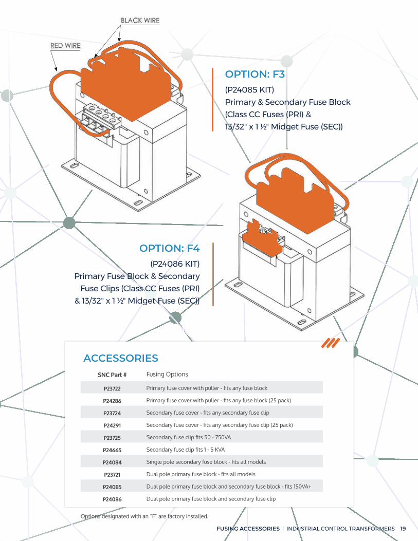
OPTION: F3(P24085 KIT)
Primary & Secondary Fuse Block
(Class CC Fuses (PRI) &
13/32" x 1 ½" Midget Fuse (SEC))
OPTION: F4(P24086 KIT)
Primary Fuse Block & Secondary
Fuse Clips (Class CC Fuses (PRI)
& 13/32" x 1 ½" Midget Fuse (SEC))
ACCESSORIESSNC Part # Fusing Options
P23722 Primary fuse cover with puller - fits any fuse block
P24286 Primary fuse cover with puller - fits any fuse block (25 pack)
P23724 Secondary fuse cover - fits any secondary fuse clip
P24291 Secondary fuse cover - fits any secondary fuse clip (25 pack)
P23725 Secondary fuse clip fits 50 - 750VA
P24665 Secondary fuse clip fits 1 - 5 KVA
P24084 Single pole secondary fuse block - fits all models
P23721 Dual pole primary fuse block - fits all models
P24085 Dual pole primary fuse block and secondary fuse block - fits 150VA+
P24086 Dual pole primary fuse block and secondary fuse clip
Options designated with an “F” are factory installed.

FUSING ACCESSORIES
Fusing Sizing Chart
20
Voltage/ VA
25 45 50 75 100 150 200 250 300 350 500 750 1000 1500 2000 3000 5000
12 3.2 6.25 6.25 10 12 15 20 25 30
23 1.8 3.2 3.5 5 7 10 12 15 15 20 30
24 1.6 3 3.2 5 6.25 10 12 15 15 20 30
25 1.6 3 3.2 5 6.25 10 12 15 15 15 25
90 0.4 0.8 0.8 1.3 1.8 2.5 3.5 4.5 5 6.25 9 12 15 25 30
95 0.4 0.75 0.8 1.3 1.6 2.5 3.5 4 5 6 8 12 15 20 30
100 0.4 0.7 0.8 1.25 1.6 2.5 3.2 4 5 5.6 8 12 15 20 25
110 0.3 0.6 0.75 1 1.5 2 3 3.5 4.5 5 7.5 10 12 15 25
115 0.3 0.6 0.7 1 1.4 2 2.8 3.5 4 5 7 10 12 15 25
120 0.3 0.6 0.6 1 1.3 2 2.5 3.2 4 4.5 6.25 10 12 15 25
220 0.25 0.3 0.3 0.5 0.75 1 1.5 1.8 2 2.5 3.5 5.6 7.5 10 12 15 30
230 0.25 0.3 0.3 0.5 0.7 1 1.4 1.8 2 2.5 3.5 5 7 10 12 15 30
240 0.25 0.3 0.3 0.5 0.6 1 1.3 1.6 2 2.25 3.2 5 6.25 10 12 15 30
SECONDARY STANDARD FUSE RATING
Voltage/ VA
25 45 50 75 100 150 200 250 300 350 500 750 1000 1500 2000 3000 5000
115 0.5 0.8 1 1.6 2 3.2 4 5 6.25 7.5 10 15 20 30
120 0.5 0.8 1 1.5 2 3 4 5 6.25 7 10 15 20 30
200 0.3 0.5 0.6 0.8 1.25 1.8 2.5 3 3.5 4 6.25 9 12 17.5 25
208 0.3 0.5 0.6 0.8 1.125 1.8 2.25 3 3.5 4 6 9 12 17.5 20
220 0.25 0.5 0.5 0.8 1 1.6 2 2.8 3.2 3.5 5.6 8 10 15 20 30
230 0.25 0.4 0.5 0.8 1 1.6 2 2.5 3.2 3.5 5 8 10 15 20 30
240 0.25 0.4 0.5 0.75 1 1.5 2 2.5 3 3.5 5 7.5 10 15 20 30
277 0.25 0.4 0.4 0.6 0.8 1.3 1.8 2 2.5 3 4.5 6.25 9 12 17.5 25
380 0.25 0.3 0.3 0.5 0.6 0.8 1.3 1.6 1.8 2.25 3.2 4.5 6.25 9 12 17.5 30
400 0.25 0.25 0.3 0.4 0.6 0.8 1.25 1.5 1.8 2 3 4.5 6.25 9 12 17.5 30
PRIMARY STANDARD FUSE RATING

FUSING SIZING CHART | INDUSTRIAL CONTROL TRANSFORMERS 21
Voltage/ VA
25 45 50 75 100 150 200 250 300 350 500 750 1000 1500 2000 3000 5000
415 0.25 0.25 0.3 0.4 0.6 0.8 1.125 1.5 1.8 2 3 4.5 6 9 12 17.5 30
440 0.25 0.25 0.25 0.4 0.5 0.8 1 1.4 1.6 1.8 2.8 4 5.6 8 10 15 25
460 0.25 0.25 0.25 0.4 0.5 0.8 1 1.3 1.6 1.8 2.5 4 5 8 10 15 25
480 0.25 0.25 0.25 0.4 0.5 0.75 1 1.3 1.5 1.8 2.5 3.5 5 7.5 10 15 25
550 0.25 0.25 0.25 0.3 0.4 0.6 0.8 1 1.3 1.6 2 3.2 4.5 6.25 9 12 20
575 0.25 0.25 0.25 0.3 0.4 0.6 0.8 1 1.3 1.5 2 3.2 4 6.25 8 12 20
600 0.25 0.25 0.25 0.3 0.4 0.6 0.8 1 1.25 1.4 2 3 4 6.25 8 12 20
PRIMARY STANDARD FUSE RATING
PRIMARY AND SECONDARY PROTECTION*Fuse sizing is based on NEC 450.3
Rated Secondary Current in Amps Maximum Primary Fuse Size Maximum Secondary Fuse
Less than 9 amps 250% or next size smaller 167% or next size smaller
Greater than or equal to 9 amps 250% or next size smaller 125% or next size smaller

22
CONNECTION DIAGRAMS
Connection Diagrams
GROUP A
GROUP E
GROUP I
GROUP C
GROUP G
GROUP B
GROUP FGROUP D
GROUP H

CONNECTION DIAGRAMS | INDUSTRIAL CONTROL TRANSFORMERS 23
GROUP M GROUP N
GROUP J
GROUP L
GROUP S
GROUP K
Learn more about how
our products can positively
impact your operation.
www.sncmfg.com
920-231-7370

Transforming tomorrow.www.sncmfg.com
MANUFACTURING CO., INC.
PROPRIETARY AND CONFIDENTIAL The information contained in this document is the sole property of SNC MFG CO., INC. Any reproduction in part or as a whole without the written permission of SNC MFG CO., is prohibited.