transformer practice 1000194704
TRANSCRIPT
8/11/2019 Transformer Practice 1000194704
http://slidepdf.com/reader/full/transformer-practice-1000194704 1/290

8/11/2019 Transformer Practice 1000194704
http://slidepdf.com/reader/full/transformer-practice-1000194704 2/290

8/11/2019 Transformer Practice 1000194704
http://slidepdf.com/reader/full/transformer-practice-1000194704 3/290

8/11/2019 Transformer Practice 1000194704
http://slidepdf.com/reader/full/transformer-practice-1000194704 4/290

8/11/2019 Transformer Practice 1000194704
http://slidepdf.com/reader/full/transformer-practice-1000194704 5/290

8/11/2019 Transformer Practice 1000194704
http://slidepdf.com/reader/full/transformer-practice-1000194704 6/290

8/11/2019 Transformer Practice 1000194704
http://slidepdf.com/reader/full/transformer-practice-1000194704 7/290
TKANSFORMER
PRACTICE
MANUFACTURE, ASSEMBLING,
CONNECTIONS,
OPERATION
AND TESTING
BY
WILLIAM
T.
TAYLOR,
F.R.G.S.
FELLOW,
A. I. E.
E.,
M.
AM.
80C. M.
E.,
M. I. E.
E.,
ETC.
Second Edition
Entirely
Rewritten,
Enlarged
and
Reset
Tenth
Impression
McGRAW-HILL
BOOK
COMPANY,
Inc.
NEW YORK: 370
SEVENTH AVENUE
LONDON:
6
8
BOUVERIE
ST.,
E. C.
4
1913

8/11/2019 Transformer Practice 1000194704
http://slidepdf.com/reader/full/transformer-practice-1000194704 8/290
Copyright,
1909,
1913,
by
the
McGraw-Hill
Book
Company,
Inc.
PRINTED
IN THE
UNITED
STATES
OF
AMERICA
K
''
THE
MAPLE
PRESS
COMPANY,
YORK,
PA.
8/11/2019 Transformer Practice 1000194704
http://slidepdf.com/reader/full/transformer-practice-1000194704 9/290
PREFACE
TO SECOND
EDITION
The
writer
seeks
to
keep
this
book
practical
and for
a
reference
on
all
matters
connected
with
the
operation
of
transformers
and
static
induction
apparatus.
It
is
particularly
intended
for
those
who
are
operating
or
constructing
plants
or
transformers
and
is
written with
the
view
of
assisting
engineers
out
of
certain
operat-ng
difficulties
which
they
can
readily
solve
when
they
are
short
of
the
right
apparatus
and
need
a
temporary
arrange-ent
such
as
using
certain
changes
of
phases.
New
schemes
of
any
kind
will be
appreciated
and
will
add
to
the
value
of
this
book.
William
T,
Taylor.
Chaplanca,
Peru,
South
America,
August,
1913.
I
\
'i.'

8/11/2019 Transformer Practice 1000194704
http://slidepdf.com/reader/full/transformer-practice-1000194704 10/290
PREFACE
TO
FIRST
EDITION
Although
much has been
written
on
the fundamental
principles
of
transformers,
little
data have been
published
concerning
their
connection,
installation
and
operation.
It
was
this
lack
ot
easily
available
information
and
the
widespread
desire of
operators
and
engineers
in
the field
to
possess
such
information,
that
led the author
to
put
in
type
these
notes,
which
had been
written
up
in
the
course
of
a
number
of
years
of
experience
in
the
field.
A
working
knowledge
of
the
fundamental
principles
of
electrical
engineering
is
presupposed,
and for
this
reason
the
treatment
does
not
go
into
the
whys
and wherefores
very
deeply,
but
simply
states
the
facts
in
as
few
words
as
possible.
To aid
in
understanding quickly
the
phase
relations and relative
values of
the various e.m.fs. and
currents
involved
in
a
given
system,
vector
diagrams
are
given
with
all
diagrams
of
circuit connections.
W.
T. Taylor.
Baramulla, Kashmir, India,
December,
1908.
VI

8/11/2019 Transformer Practice 1000194704
http://slidepdf.com/reader/full/transformer-practice-1000194704 11/290
I
CONTENTS
Page
Preface
v
Chapter
I.
Introduction
1
II.
Simple
Transformer
Manipulations
22
III.
Two-phase
Transformer Connections
30
IV.
Three-phase
Transformation
System
39
V.
Three-phase
Transformer
Difficulties
84
VI.
Three-phase Two-phase Systems
and Transformation
....
97
VII.
Six-phase
Transformation
and
Operation
109
VIII.
Methods of
Cooling
Transformers
117
IX.
Construction,
nstallation
and
Operation
of
Large
Transformers
136
X.
Auto
Transformers
170
XI.
Con.stant-current Transformers and
Operation
178
XII.
Series
Transformers and Their
Operation
186
XIII.
Regulators
and
Compensators
209
XIV.
Transformer
Testing
in
Practice
227
XV. Transformer
Specifications
258
Appendix
270
Index
....
273
Vll

8/11/2019 Transformer Practice 1000194704
http://slidepdf.com/reader/full/transformer-practice-1000194704 12/290

8/11/2019 Transformer Practice 1000194704
http://slidepdf.com/reader/full/transformer-practice-1000194704 13/290
TRANSFORMER PRACTICE
CHAPTER
I
INTRODUCTION
Development
of
Art
of
Transformer
Construction
The
development
of
the
alternating-current
transformer dates
back
about
25
years.
At
that
time
very
little
was
known
re-arding
design
for
operation
at
high
voltages,
and the
engineer
of the
present
day
can
scarcely
realize
the
difficulties
encountered
in the
construction
of
the
early
transformers.
The
high-voltage
transformer
made
long-distance
trans-ission
work
possible,
and
the
increased distances
of
transmission
stimulated
the
design
of
large
transformers.
In
the
early days
of
transformer
development
as
many
as
15 to
20
transformer
secondary
windings
have
been
connected
in
series
to
facilitate
the
operation
of
a
long-distance
transmission
system,
the maxi-um
rating
of each transformer
being
not
greater
than
10
kw.
However,
a
method
of
constructing
large
transformers
has
long
been
devised
by
which
an
enormous
amount
of
power
may
be
transformed
in
a
single
unit.
Such
designs
embody
principles
of
insulation
for
high
voltages
and
various
methods for
maintain-ng
a
low
operating temperature.
Ten
years
ago
a
500-kilowatt
unit
was
considered
to
be
a
large
size
of
transformer.
The
history
of
ten
years'
development
has shown
a
most
interesting
process
of
evolution: it
has
marked
more
than
a
tenfold
increase
in
size
up
to
the
present
day.
Going
back
to
part
of the
history
of
transformer
manufacturing
we
find that the first transformer used
by Faraday
in his historic
experiments
had for their
magnetic
circuit
a
closed
ring
of iron.
Varley
in the
year 1856
pointed
out
the
disadvantage
of
leaving
the
magnetic
circuit
open,
gave
it
a
closed
path by
bending
back
and
overlapping
the
end
of the
straight
iron
wire
core.
In
the
early
days
of
electric
lighting
Ferranti modified
Varley's
method
by
using,
instead
of
iron
wires,
strips
of sheet
iron bent
back and
interlaced.
The
nearest
approach
to
the
present
day practice
1

8/11/2019 Transformer Practice 1000194704
http://slidepdf.com/reader/full/transformer-practice-1000194704 14/290
2
STATIONARY
TRANSFORMERS
was
to
embed
link-shaped
coils
in
the
recesses
of
a core
built
up
of
shaped
stampings,
afterward
completing
the
magnetic
circuit
either
with
sheets of
laminations
or
with
strips
interlaced with
the
ends of
the
prejectinglegs.
There
is
good
reason
to
believe
that from this
construction
the
Shell
type
transformer of
to-ay
received its
name.
00
00
16.000
15,000
14,000
13.000
12,000
11.000
2
10,000
0)
Oi
S
9.000
ii
8.000
t
7.000
M
6,000
5,000
4.000
3.000
2,000
1.000
0
at a
\
I
J
I
1
1
I
_^_
I
wm-^,-^^wmm^
_
i
1 1
I
__I___^___,,,j.:
=.^^
K.V.-Amp.
.
K.-Volta
160
150
140
130
120
110
100
3
90
I
80
I
70
60
50
40
30
20
10
0
Fig.
1. Transformer
development.
Not
very
many
years
ago
it
was
a
question
among
very
prominent
engineers
whether
15,000-volt
transformers
could
be
made
to
work.
Before
the
time
engineers
conceived
the
idea
of
drying
trans-ormer
oil,
it
was
not
uncommon
to
see
transformers without
any
solid material
between
coils
the
oil
space
being
relied
on
for
insulation.
At
that
time
the
transformer
was
the
only
limiting
feature
of
transmission.
We have
only
to
go
back about
11
years
to
find the
first
50,000-
and
60,000-volt
transformer
actually
operating
(see
Fig.
1).
At
the
present
time
we are
actuallyoperating
transformers
at
145,000
volts
with
as
great
safety
and
with
less
liability
f
break-down
than
formerly
was

8/11/2019 Transformer Practice 1000194704
http://slidepdf.com/reader/full/transformer-practice-1000194704 15/290
r
INTRODUCTION
3
experienced
in
operating
at
15,000
volts,
and the
actiial
voltage
limit of the
transformer
is not
yet
in
sight,
but
on
the
contrary
the
transmission
line
itselfis
the
limiting
feature in
the
voltage
or
the
distance
of
transmission.
About
16
years
ago
the
first
20,000-volt
transformer
was
made.
At
the
present
time the
commercial manufacture
of
175,000-volt
power
transformers
is
being
considered.
Fig.
1
represents
the
development
of
singlecapacity
transformers
up
to
the
year
1913.
Increased
voltage
means,
of
course,
increased
kv-a
capacity
of
units,
not
only
as
regards
the
transformers
themselves
but
in
generators
and
prime
movers.
Glancing
back
25
years
we
enter
upon
a
time
when
alternating
currents
were
grievously
fought
in the Law Courts
as
being
a
current
both
'^
dangerous
and
impracticable.
Just
about
20
years
ago
the
period
when
three-phase
star
and
delta
systems
of
electric
distribution
were
recognized
as
practicable
or
commercial
use
we
find
universal
opposition
to
high
voltages
(above
1500
volts)
and
large
units
(above
500
kw.).
Going
back
only
10
years
about the
period
when
50,000
and
60,000
volts
were
recognized
as
practicable
for transmission
purposes
large
commercial units
and
large
commercial electric
power
systems,
as
recognized
to-day,
were
universally
onsidered
as
impossible,
as
absolutely
unreliable
or
decidedly
dangerous.
In
view
of
the
three
above
decades,
practically
accepted
throughout
the entire
engineering
world,
we
actually
have
at
the
present
time electric
power
systems
operating
as one
company
and
one
centralized
system
delivering
over
200,000
kw.,
and
single
units
for
commercial
electric
power purposes,
as:
Steam
turbines
(horizontal
type)
of
33,000
h.p.
Steam
turbines
(verticalype)
of
40,000
h.p.
Water
turbines
(vertical
type)
of
20,000
h.p.
Turbo-generators (horizontaltype)
of
25,000
kw.
Turbo-generators
(vertical
ype)
of
30,000
k
w.
Generators
(vertical
type)
of
12,500
kw.
Transformers
(shell-type)
f
14,000
kw.
and
Transformers
(three-phase
group
of
three)
of
18,000
kw.
Fundamental
Principles.
The transformer consists
primarily
of
three
parts:
the
primary
winding,
the
secondary
winding,
and
the
iron
core.
The
primary
winding
is
connected
in
one
cir-uit,
the
secondary
in
another,
and
the
core
forms
a
magnetic
circuit
which links the
two
together.

8/11/2019 Transformer Practice 1000194704
http://slidepdf.com/reader/full/transformer-practice-1000194704 16/290
4
STATIONARY TRANSFORMERS
The
principle
f the
constant-potential
ransformer
is
easily
explained
if
we
neglect
the
slight
effects
of
resistance
drop
in
the
windings,
leakage
of
magnetic
flux,
and
the losses.
The
primary winding
is
connected
to
a
source
of
e.m.f,,
which
con-ection
would
constitute
a
short-circuit
were
it
not
for
the
periodic
changing
in
value
which
permits
the
flux
produced
by
the
current
to
generate
a
counter
e.m.f.
which
holds
the
current
down
to
a
value
just
sufficient
to
produce
that value of
flux
necessary
to
generate
an
e.m.f.
in
the
primary
and
equal
and
opposite
to
the
impressed
e.m.f.
This
same
flux
is
sur-ounded
by
the
turns
of the
secondary
winding,
the
same
e.m.f.
being
generated
in
each
turn
of
wire
whether
primary
or
secondary.
If
El
is
the
impressed
e.m.f.
:e
=
e.m.f.
per
turn.
wherein
A^^
is
the
number of
primary
turns,
number of
secondary
turns.
Then
if
A^,
is
the
ff
and
^2
-^2^
secondary
e.m.f.
~
=~ =
ratio
of
transformation.
A^2 E^
When
Ni
is
greater
than
N2,
the
transformer
is
called
a
step-
down
transformer and when
A^^
is
less than
N2
it is
called
a
step-up
transformer.
The reader
will
understand that
a
step-up
transformer
may
be

8/11/2019 Transformer Practice 1000194704
http://slidepdf.com/reader/full/transformer-practice-1000194704 17/290
INTRODUCTION 5
used
as
a step-down
transformer,
or
vice
versa.
The
primary
is
the
winding
upon
which
the e.m.f.
is
impressed.
The
primary
and
secondary
windings
of
a
transformer
possess
both
resistance
and
reactance,
and the
secondary
values
may
be
reduced
to
primary
terms
by
multiplying
them
by
the
square
of
the
ratio
of
transformation.
This
applies
to
the
load
resistance
and
reactance
as
well.
Thus,
consider
a
circuit
containing
a
transformer,
a
load,
etc.,
as
shown
in
Fig.
2.
Obviously,
to
main-ain
the
core
flux
a
magnetizing
current
is
required,
which
of
course
must
pass
through
the
primary
winding.
(6)
is
an
exact
duplicate
of
the
transformer
(a).
The
factors
R
and
Xg are
respectively
he
resistance and
reactance
of the
primary;
R'X's
the
respective
resistance
and
reactance
of
the
secondary
winding,
and
R
and
Xg
the load
resistance
and
reactance.
This
representation
s
about
the
simplest
for
treat-ent
of the
transformer circuits.
Points
in
the
Selection
of
Transformers
The electricalchar-cteristic
of
a
transformer
are
mostly
dependent
upon the
quality,
arrangement
and
proportion
of the
iron
and
copper
that
enter
into its construction.
The
losses
are
of
two kinds:
the
copper
loss,
due
to
the
current
through
the
coils;
and the
iron
loss,
caused
by
the
reversing
of
the
magnetic
flux
in
the
core.
These
losses
appear
as
heat,
and suitable
means
must
be
provided
for
the
disposal
of
this
heat.
In
selecting
a
transformer for
a
given service,
t is advisable
to
consider
first:
(a)
The
ratio
of
iron
and
copper
loss,
which
should
be
such
that
the total
cost
of
the
losses
is
a
minimum.
(b)
The
cost
of
the
transformer for
a
given
service
and the
cost
of
its
total
losses should
be
a
minimum.
The
cost
of
a
transformer for
a
given
service
depends
on
the
amount
which
must
be
paid
for the losses
during
the
life
of
the
transformer
and
on
the
first
cost
of
the
transformer
itself.
In
considering
the losses
and
price
paid
for
a
transformer
together,
the losses
may
be
conveniently
represented
as a
capital
cost
by
dividing
their
annual
cost
by
the
interest
and
depreciation
factor.
Safety
to
life,urability,
nd
economy
are
essential
features
of
this
apparatus
in
its
ability
to
give
continuous
and
uninterrupted
service. These
factors,
sometimes in
part
and
sometimes
entire,
are
sacrificed
to
obtain
a
higher
efficiency,
specially
in
high
volt-ge
transformers where
so
much
insulation
has
to
be
used. This

8/11/2019 Transformer Practice 1000194704
http://slidepdf.com/reader/full/transformer-practice-1000194704 18/290
6
STATIONARY
TRANSFORMERS
is
not
considered
good
practicealthough
the
higher
efficiency
is
obtained,
and
a
transformer
designed
and
built
with
the
main
object
of
efficiency
t
the
expense
of
safety
and
reliability
finally
brings
discredit
to
its
maker.
The
loss
in
revenue
alone
due
to
the
failure of
a
large
power
transformer would
more
than
offset
the
saving
of
several
years
in
gaining
an
additional
fraction
of
1
per
cent,
in
efficiency,
ot
counting
the
great
loss
of
confi-ence
and
prestige
on
the
part
of
the
customer.
The
applica-ion
of
knowledge
gained
by
many
years
of
constant
and
care-ul
study
of
all the
properties
and
characteristics
of
trans-ormers
in
actual
practice
has
placed
this
type
of
apparatus
on
a
plane
which
we
may
now
call
both
safe and
reliable
for
opera-
ing
voltages
as
high
as
110,000
volts.
Looking
back
over
the
development
of the transformer
we
do
not
pass very
many
years
before
we
enter
the
time
when
large
units
of
moderately
high
voltage(20,000
volts)
were
considered
by
manufacturers
a
tedious
if
not
altogether
a
dangerous
undertaking,
in
fact
quite
as
danger-us
as
designing
and
building
a
unit in
these
days
to
give
an
out-ut
of
20,000
kw.
at
200,000
volts.
Cooling.
A
well-designed
transformer
should
not
only
main-ain
a
low
average
temperature
but the
temperature
should
be
uni-orm
throughout
all of
its
parts.
The
only
effective
way
of
insur-ng
uniform
temperature
is
to
provide
liberal
oil
ducts between
the
various
parts
of the
transformer,
and
these
should
be
so
arranged
in relation
to
the
high
and low
voltage
windings
as
to
give
the
best
results
without
sacrificing
ther
important
factors.
Ducts
necessarily
use
much
available
space
and
make
a
high
voltage
transformer
of
given efficiency
ore
expensive
than
if
the
space
could
be
completely
filled
with
copper
and
iron;
in view
of the
reliability
nd low deterioration of
a
transformer of this
type,
experience
has demonstrated that the
extra
expense
is
warranted.
For
various
reasons
the
temperature
rise in
a
transformer
is
limited.
The
capacity
for work
increases
directly
as
the
volume
of
material,
nd the
radiating
surface
as
the
square
of
the
dimen-ions;
therefore,
it is
evident
that
the
capacity
for
work
increases
faster
than the
radiating
surface.
The
amount
of heat
developed
in
a
transformer
depends
upon
its
capacity
and
efficiency.
For
instance,
in
a
500-kw.
trans-ormer
of
98
per
cent,
efficiency
there is
a
loss
at
full load of
about
7.5
kw.
;
and
since
this
loss
appears
as
heat,
it
must
be
disposed
of
in
some
way,
or
the
temperature
of the transformer
8/11/2019 Transformer Practice 1000194704
http://slidepdf.com/reader/full/transformer-practice-1000194704 19/290
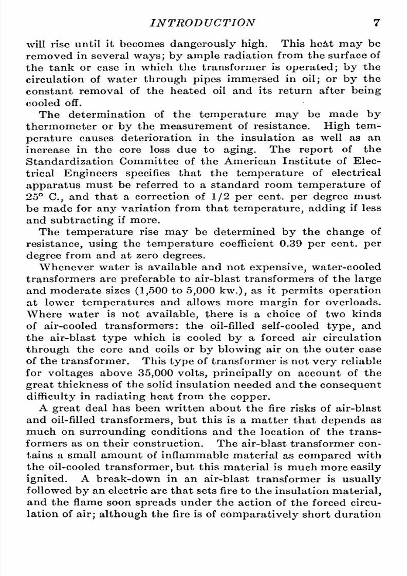
INTRODUCTION
7
will rise
until
it
becomes
dangerously
high.
This hea,t
may
be
removed
in
several
ways;
by
ample
radiation
from the surface
of
the
tank
or case
in
which
the transformer
is
operated;
by
the
circulation
of
water
through
pipes
immersed
in
oil;
or
by
the
constant
removal
of
the heated
oil
and
its
return
after
being
cooled
off.
The
determination
of
the
temperature
may
be
made
by
thermometer
or
by
the
measurement
of
resistance.
High
tem-erature
causes
deterioration in
the
insulation
as
well
as
an
increase
in
the
core
loss
due
to
aging.
The
report
of
the
Standardization
Committee
of the
American
Institute
of
Elec-rical
Engineers specifies
hat
the
temperature
of electrical
apparatus
must
be
referred
to
a
standard
room
temperature
of
25
C,
and
that
a
correction
of
1/2
per
cent,
per
degree
must
be
made for
any
variation
from
that
temperature,
adding
if less
and
subtracting
if
more.
The
temperature
rise
may
be
determined
by
the
change
of
resistance,using
the
temperature
coefficient
0.39 per
cent,
per
degree
from
and
at
zero
degrees.
Whenever
water
is
available
and
not
expensive,
water-cooled
transformers
are
preferable
to
air-blast transformers
of the
large
and
moderate
sizes
(1,500
to
5,000 kw.),
as
it
permits
operation
at
lower
temperatures
and allows
more
margin
for
overloads.
Where
water
is
not
available,
here
is
a
choice
of
two
kinds
of
air-cooled transformers: the oil-filled self-cooled
type,
and
the
air-blast
type
which
is
cooled
by
a
forced
air
circulation
through
the
core
and
coils
or
by
blowing
air
on
the outer
case
of
the transformer. This
type
of
transformer
is
not
very
reliable
for
voltages
above
35,000
volts,
principally
n
account
of
the
great
thickness
of
the solid insulation
needed
and the
consequent
difficulty
n
radiating
heat
from
the
copper.
A
great
deal has been
written about
the fire
risks
of
air-blast
and
oil-filled
transformers,
but
this
is
a
matter
that
depends
as
much
on
surrounding
conditions
and
the location
of the
trans-ormers
as
on
their construction.
The
air-blast
transformer
con-ains
a
small
amount
of
inflammable
material
as
compared
with
the
oil-cooled
transformer,
but
this
material
is
much
more easily
ignited.
A break-down
in
an
air-blast
transformer
is
usually
followed
by
an
electric
arc
that
sets
fire
to
the
insulation
material,
and the
flame
soon
spreads
under the
action
of
the forced
circu-ation
of
air;although
the fire
is
of
comparatively
short
duration

8/11/2019 Transformer Practice 1000194704
http://slidepdf.com/reader/full/transformer-practice-1000194704 20/290
8 STATIONARY
TRANSFORMERS
it is
quite
capable
of
igniting
the
building
unless
everything
near
the transformer
is
of
fireproof
construction. The chance
of
an
oil-filledtransformer
catching
fire
on
account
of
a
short-
circuit
in
the
windings
is
extremely
small,
because oil will
only
burn
in
the
presence
of
oxygen,
and,
as
the
transformer
is
com-letely
submerged
in
oil,
o
air
can
get
to
it.
Moreover,
the oil
used
in
transformers
is
not
easilyignited;
it
will
not
burn
in
open
air
unless its
temperature
is
first
raised
to
about
400
F.,
and
with
oil
at
ordinary
temperatures,
a
mass
of
burning
material
can
be
extinguished
as
readily
by
immersing
it in
the
oil
as
in
water.
In
fact,
the chief
danger
of fire is
not
that the
oil
may
be
ignited
by
any
defect
or arc
within
the
transformer,
but
that
a
fire
in
the
building
may
so
heat the
oil
as
to
cause
it
to
take
fire.
The
idea
of
placing
oil-filled
transformers
into
separate compartments
is
not
thought
of
so
seriously
as
it
was
some
years
ago,
although
it
does
not
apply
in
every
case
and
therefore
it
is
necessary
to
consider
carefully
when
selecting
this
type
of
transformer.
Of the
large
number of factors in the
make-up
of
a
transformer
only
four
which
the
operating
manager
is
particularly
nxious
to
know
enter
into
the
operating
costs,
namely:
the
coris
and
copper
losses,
temperature,
efficiency
and
regulation.
All
of
these
costs
(since
they
might
be
called
costs
as
they
include the
cost
of
generating
such losses
and
of
suppl}'ing
the
station
capacity
with which
they
generate
them)
represent
quite
a
large
amount
of energy
during
the
life
of the transformer.
Losses.
The
hysteresis
and
eddy
current
losses
are
generally
combined
under the
term
of
core
loss,
this
loss
occurring
in
all
magnetic
material
which
is
subject
to
alternatingmagnetic
stresses.
The
hysteresis
loss,
as
is
generally
known,
may
be
defined
as
the work
done
in
reversing
the
magnetism
in
the
steel,
and
it
may
be
considered
as
due
to
the
molecular
friction
from the reversal of
magnetism,
this friction
manifesting
itself
as
heat.
The
amount
of
hysteresis
in
a
given
steel
varies
with
the
composition,
with
the
hardness,
with
the
frequency
of
reversal
of
magnetism,
with
the
maximum induction
at
which
the
steel
is
worked,
and the
temperature.
The
hysteresis
oss varies
approxi-ately
as
the
1.6
power
of
induction,
nd
directly
as
the fre-uency.
The
eddy
current
loss
varies
inversely
as
the
ohmic
resistance,
directly
as
the
square
of
the
induction,
and decreases
as
the
temperature
increases.
It
is
greater
in thick
laminations
than
in
thin
(hysteresisbeing
greater
in
hard
steel than
in
soft

8/11/2019 Transformer Practice 1000194704
http://slidepdf.com/reader/full/transformer-practice-1000194704 21/290
INTRODUCTION 9
steels),
t
is
also
greater
as
the
insulation
between
adjacent
lamin-tions
is
less.
Lowering
the
frequency
of
supply
will result
in
increased
hysteresis
and
higher
temperature
in
the
iron;
reducing
the
frequency
from
say
133
to 125
cycles
will entail
an
increased
hysteresis
of about
4
per
cent.,
and
a
reduction
from
60 to
50
cycles
will
raise the
hysteresis
pproximately
10
per
cent.
For
equal
output
there
will
not
exist
any
change
in
the
copper
loss,
but
in
the
case
of
large
power
transformers
the
in-reased
temperatures
due
to
excessive
iron
losses
will
materially
decrease
the
output,
and
the
normal
rated
secondary
current
or
low
voltage
current
will
become
a
virtual
overload.
Iron
loss
and
exciting
current
in addition
to
decreased kw.
capacity
of
the
transformer
mean
greater
coal
consumption,
all
these factors
being directly
opposed
to
commercial
operation,
and
as
this iron
loss
is
constant
while
the
transformer
is
con-ected
to
the
system,
no
matter
what the
load
may
be,
the
total
yearly
loss will
represent
a
great
loss
in
revenue.
While
the
iron
loss
is
practically
onstant at
all
loads,
the copper
or
P R loss
varies
as
the
square
of the
current
in
both
the
high
and low
voltage
windings.
The
output
is
the
total
useful
energy
de-ivered
to
the
primary,
and
consists of
the
output
energy
plus
the
iron
loss
at
the
rated
voltage
and
frequency
plus
the
copper
loss due
to
the
load
delivered.
This
loss
is
within
easy
control
of the
designer,
s
a
greater
or
less
cross-section
of
copper
may
be
provided
for
the desired
per
cent,
regulation.
In
a
transformer
core
of
a
given
volume
and
area,
the
number of
turns
for the
required
iron
loss
are
fixed. To
secure
the
desired
copper
loss
advantage
is
taken
of
a
form of
coil wherein
the
mean
length
per
turn
is
kept
as
low
as
possible
with
the
necessary
cross-section of
copper.
If
the
form
of
coil is
rectangular
it
is
evident
that the
mean
length
per
turn
of
the conductor would
be
increased,
provided
the
same
cross-section
or
area
of the
core
is
enclosed,
so
in
order
to
secure
the shortest
length
per
mean
turn
consistent
with
good
construction it is
necessary
to
adopt
the
square
core
in which
the
corners
have
been
cut
off.
Also,
in
order
that
the
greatest
amount
of conductor
may
be
allowed
for
the available
space,
all
wire
entering
into
the low and
high
voltage
windings
is either
square
or
rectangular
in
shape,
as
by
using
this
form
of conductor
the
area
is increased
by
about
33
per
cent,
over
that
of
ordinary
round
wire.
This
method
permits
the
copper
loss
to
be
reduced,
and
at
the
same
time
allows
a
8/11/2019 Transformer Practice 1000194704
http://slidepdf.com/reader/full/transformer-practice-1000194704 22/290
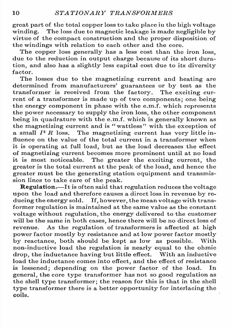
10
STATIONARY TRANSFORMERS
great
part
of
the
total
copper
loss
to
take
place
in
the
high
voltage
winding.
The loss due
to
magnetic
leakage
is
made
negligible
by
virtue
of
the
compact
construction
and the
proper
disposition
of
the
windings
with relation
to
each other and the
core.
The
copper
loss
generally
has
a
less
cost
than
the
iron
loss,
due
to
the
reduction
in
output
charge
because
of
its
short
dura-ion,
and also has
a
slightly
less
capital
cost
due
to
its
diversity
factor.
The losses
due
to
the
magnetizing
current
and
heating
are
determined from
manufacturers'
guarantees
or
by
test
as
the
transformer
is
received
from the
factory.
The
exciting
cur-ent
of
a
transformer
is
made
up
of
two
components;
one
being
the
energy
component
in
phase
with
the
e.m.f.
which
represents
the
power
necessary
to
supply
the
iron
loss,
the
other
component
being
in
quadrature
with
the e.m.f.
which is
generally
known
as
the
magnetizing
current
and
is
wattless
with
the
exception
of
a
small
P
R
loss. The
magnetizing
current
has
very
little
in-luence
on
the value of the total
current
in
a
transformer when
it
is
operating
at
full
load,
but
as
the
load
decreases the effect
of
magnetizing
current
becomes
more
prominent
until
at
no
load
it is
most
noticeable.
The
greater
the
exciting
current,
the
greater
is
the total
current at
the
peak
of the
load,
and hence
the
greater
must
be the
generating
station
equipment
and
transmis-ion
lines
to
take
care
of
the
peak.
Regulation.
It
is
often
said
that
regulation
reduces the
voltage
upon
the load
and
therefore
causes
a
direct
loss
in
revenue
by
re-ucing
the
energy
sold.
If,however,
the
mean
voltage
with
trans-ormer
regulation
is maintained
at
the
same
value
as
the
constant
voltage
without
regulation,
the
energy
delivered
to
the
customer
will
be the
same
in
both
cases,
hence there
will
be
no
direct
loss
of
revenue.
As the
regulation
of transformers
is
affected
at
high
power
factor
mostly by
resistance
and
at
low
power
factor
mostly
by
reactance,
both should be
kept
as
low
as
possible.
With
non-inductive
load the
regulation
is
nearly
equal
to
the
ohmic
drop,
the
inductance
having
but
little
effect.
With
an
inductive
load
the
inductance
comes
into
effect,
nd the effect
of
resistance
is
lessened; depending
on
the
power
factor of
the load.
In
general,
the
core
type
transformer
has
not
so
good
regulation
as
the shell
type
transformer;
the
reason
for
this
is
that
in
the
shell
type
transformer there
is
a
better
opportunity
for
interlacing
the
coils.

8/11/2019 Transformer Practice 1000194704
http://slidepdf.com/reader/full/transformer-practice-1000194704 23/290

8/11/2019 Transformer Practice 1000194704
http://slidepdf.com/reader/full/transformer-practice-1000194704 24/290
12
STATIONARY
TRANSFORMERS
operate
without
sufficient
insulation,
nd
the less
space
occupied
by
this insulation
the
more
efficient will it
be,
with
a given
amount
of
iron
and
copper.
At the
present
time
the
use
of solid
compounds
for
impregna-ion
of
the
winding
of
transformers
is
almost
universally
adopted.
The
use
of
this
compound
marks
a
great
improvement
in
the
mod-rn
transformer
because
it
helps
to
make
the
coils
mechanically
stronger
by
cementing
together
the
turns
and the
insulation
between
turns
and
layers
in
the
windings.
All
high-voltage
transformers and
practically
ll
transformers
of
any
voltage,
are
dried
and
impregnated
by
the
vacuum
process
which
is
now
considered
to
be the
most
reliable
insulating
material
and
method of
insulating.
For
this
purpose
both
asphalts
and
resins
are
the materials
available.
They
can
be
liquified
by
heat
and forced
into
the coil
in
that
condition,
and
on cooling
they
harden,
forming
a
solid
mass
(coil
and
material)
which
is,
if
well
done,
free
from
porosity
and
volatile
solvents.
The
compound
fills the porous
covering
of
the
wire-conductors,
and all other
spaces
in
the
coils
no
matter
how
small,
thus
increas-ng
the
dielectric
strength
and
preventing
moisture
from
soaking
into
the
coils.
Before
applying
this
process,
the
coils
are
thor-ughly
dried either in
a
separate
oven
or
in the
impregnating
tank.
They
are
then
placed
in
the
impregnating
tank and
heat
is
applied
until the coils
reach
a
temperature
at
which
the
impregnating
compound
is
thoroughly
fluid.
The
air in
the
tank
is
then
exhausted
by
a
vacuum
pump.
After
the
vacuum
has
exhausted
the
last
traces
of
moisture
from the
coils,
hot
compound
from
another
tank
is
drawn
into
the
impregnating
tank
until
the
coils
are
thoroughly
covered,
this condition
being
maintained until
the
coils
are
impregnated.
The
pressure gen-rally
used
is
60
to
80
lb.
per square
inch.
The time
required
under
vacuum
and
pressure
can
only
be determined
by
trial
but
usually
from three
to
six
hours'
vacuum
will
dry
any
ordinary
high-voltage
coil
not
unduly
moist.
At
the
present
time
the
fluid
point
of
some
impregnating
com-ounds
is
about
95
C,
but
it
is
possible
that
the
development
of
synthetic
gums
will
soon
reach
a
stage
which will
permit
an
actual
operating
temperature
of
130
C,
The
National
Board
of
Fire
Underwriters
specify
that the
insulation
of
nominal
2000-volt
transformers
when
heated shall
withstand
continuously
for
one
minute
a
difference
of
potential

8/11/2019 Transformer Practice 1000194704
http://slidepdf.com/reader/full/transformer-practice-1000194704 25/290
INTRODUCTION
13
of
10,000
volts
(alternating)
between
primary
and
secondary
coils
and the
core
and
a
no-load
run
of
double
voltage
for
30
minutes.
All transformers
should be
subjected
to
insulation
tests between
the
primary
and
secondary,
and the
secondary
and
core.
A
transformer
may
have
sufficient
strength
to
resist the
strain
to
which
it is
constantly subjected,
and
yet
due
to
an
imperfection
in
the
insulation
may
break down
when
subjected
to
a
slight
over-
voltage
such
as
may
be
caused
by
the
opening
of
a
high-power
circuit.
The
application
f
a
high-potential
est to
the
insulation
will
break
down
an
inferior
insulation,
r a
weak
spot
or
part
of
the
structure
in
the
insulation.
The
duration
of the
test
may
vary
somewhat
with
the
magnitude
of
the
voltage
applied
to
the
transformer.
If
the
test
be
a severe
one,
it
should
not
be
long
continued,
for
while
the
insulation
may
readily
withstand
the
application
of
a
voltage
five
or
even
six
times
the
normal
strain,
yet
continued
application
f the
voltage
may
injure
the insulation
and
permanently
reduce
its
strength.
FUNDAMENTAL
EQUATIONS
In
the
design
of
successful
transformers,
the
following
equa-ions
are
found
reliable:
Let N
=
Total
number of
turns
of
wire in series.
0
=
Total
magnetic
flux.
A
=
Section
of
magnetic
circuit
in
square
inches.
/
=
Frequency
in
cycles
in
seconds.
B
=
Lines
of
force
per square
inch.
E
=
Mean
effective
e.m.f.
4.44=
J_.
V2X;r
4 4^ f6 N
then
^
=
i:^i^^-A
d)
Equation
(1)
is
based
on
the
assumption
of
a
sine
wave
of
e.m.f.,
and
is
much used
in
the
design
of
transformers.
If the
volts,frequency,
and number of
turns
are
known,
then
we
have
._
gxio
, .

8/11/2019 Transformer Practice 1000194704
http://slidepdf.com/reader/full/transformer-practice-1000194704 26/290
8/11/2019 Transformer Practice 1000194704
http://slidepdf.com/reader/full/transformer-practice-1000194704 27/290
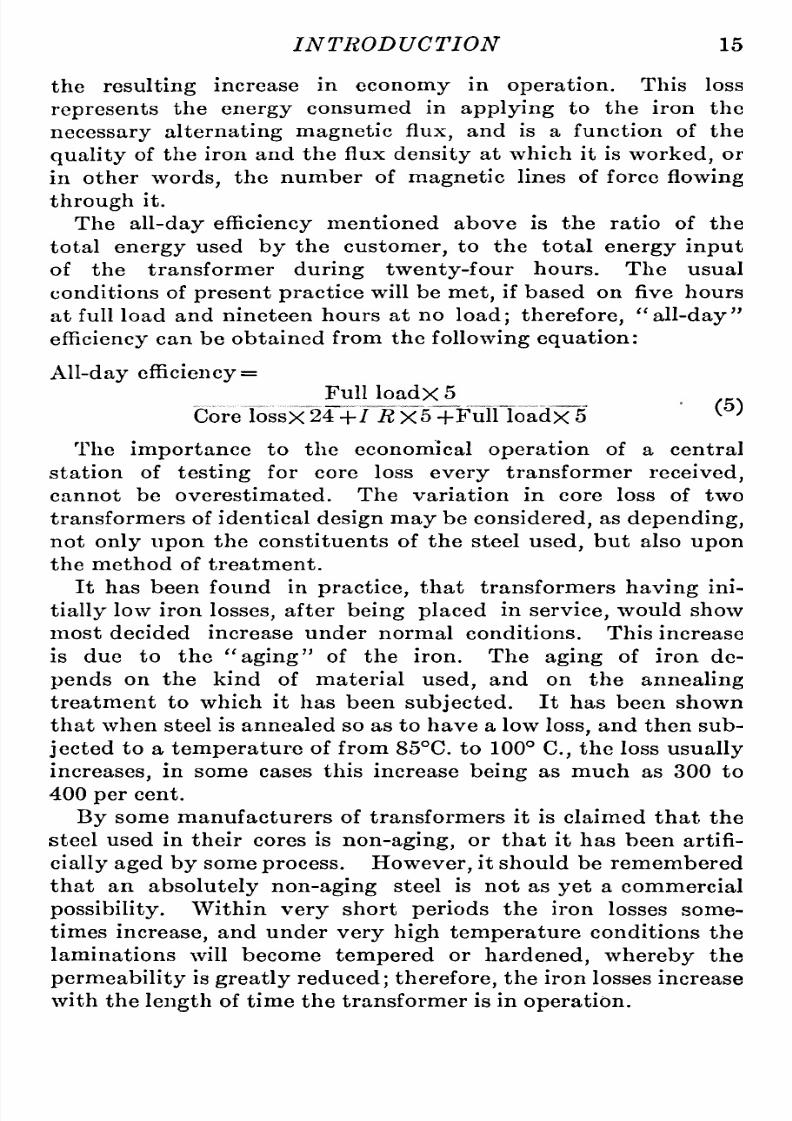
INTRODUCTION 15
the
resulting
increase
in
economy
in
operation.
This
loss
represents
the
energy
consumed
in
applying
to
the
iron
the
necessary
alternating
magnetic
flux,
and
is
a
function
of
the
quality
of
the
iron
and
the flux
density
at
which
it is
worked,
or
in
other
words,
the
number of
magnetic
lines
of force
flowing
through
it.
The
all-day
efficiency
entioned
above
is
the
ratio
of the
total
energy
used
by
the
customer,
to
the total
energy
input
of
the
transformer
during
twenty-four
hours.
The usual
conditions
of
present
practice
will
be
met,
if
based
on
five hours
at
full load
and
nineteen hours
at
no
load;
therefore,
all-day
efficiency
an
be
obtained
from
the
following
equation:
All-day
efficiency
Full
loadx
5
Core
lossX24
-|-/
i2
X5
-hFull loadx
5
^^
The
importance
to
the
economical
operation
of
a
central
station
of
testing
for
core
loss
every
transformer
received,
cannot
be overestimated. The variation in
core
loss
of
two
transformers of
identical
design
may
be
considered,
s
depending,
not
only
upon
the
constituents
of the steel
used,
but also
upon
the method of
treatment.
It has
been
found
in
practice,
hat
transformers
having
ini-ially
low
iron
losses,
after
being
placed
in
service,
ould
show
most
decided
increase
under
normal
conditions. This increase
is
due
to
the
aging
of the
iron.
The
aging
of
iron
de-ends
on
the
kind
of
material
used,
and
on
the
annealing
treatment to
which
it
has
been
subjected.
It has
been shown
that when steel
is
annealed
so as
to
have
a
low
loss,
and
then
sub-ected
to
a
temperature
of
from
85 C.
to
100
C,
the
loss
usually
increases,
n
some cases
this increase
being
as
much
as
300 to
400
per
cent.
By
some
manufacturers of
transformers
it is claimed
that the
steel
used
in their
cores
is
non-aging,
or
that
it
has
been
artifi-ially
aged by
some
process.
However,
it
should
be remembered
that
an
absolutely
non-aging
steel
is
not
as
yet
a
commercial
possibility.
Within
very
short
periods
the
iron
losses
some-imes
increase,
nd under
very
high
temperature
conditions
the
laminations will
become
tempered
or
hardened,
whereby
the
permeability
is
greatly
reduced;
therefore,
the
iron
losses increase
with
the
length
of
time
the
transformer
is
in
operation.

8/11/2019 Transformer Practice 1000194704
http://slidepdf.com/reader/full/transformer-practice-1000194704 28/290
8/11/2019 Transformer Practice 1000194704
http://slidepdf.com/reader/full/transformer-practice-1000194704 29/290
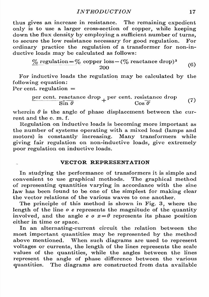
INTRODUCTION
17
thus
gives
an
increase in
resistance.
The
remaining expedient
only
is
to
use a
larger
cross-section of
copper,
while
keeping
down the
flux
density
by
employing
a
sufficient
number
of
turns,
to secure
the low
resistance
necessary
for
good
regulation.
For
ordinary
practice
the
regulation
of
a
transformer for
non-in-uctive
loads
may
be
calculated
as
follows:
%
regulation
%
copper
loss
(%
reactance
drop)^
200
(6)
For
inductive
loads
the
regulation
may
be calculated
by
the
following
equation:
Per
cent,
regulation
per
cent, reactance
drop
per
cent,
resistance
drop
.
SiiT^
^
Cosl'
^^
wherein
0
is
the
angle
of
phase
displacement
between
the
cur-ent
and
the
e.
m.
f.
Regulation
on
inductive
loads
is
becoming
more
important
as
the
number
of
systems operating
with
a
mixed
load
(lamps
and
motors)
is
constantly
increasing.
Many
transformers
while
giving
fair
regulation
on
non-inductive
loads,
give extremely
poor
regulation
n
inductive
loads.
VECTOR REPRESENTATION
In
studying
the
performance
of transformers
it
is
simple
and
convenient
to
use
graphical
methods. The
graphical
method
of
representing
quantities
varying
in
accordance
with
the
sine
law
has
been
found
to
be
one
of
the
simplest
for
making
clear
the
vector
relations
of the
various
waves
to
one
another.
The
principle
of
this
method
is
shown
in
Fig.
3,
where the
length
of the
line
o e
represents
the
magnitude
of the
quantity
involved,
and
the
angle
e o x
=
d
represents
its
phase
position
either in time
or
space.
In
an
alternating-current
ircuit the relation
between the
most
important
quantities
may
be
represented by
the
method
above
mentioned.
When such
diagrams
are
used
to
represent
voltages
or
currents,
the
length
of
the
lines
represents
the
scale
values
of the
quantities,
while
the
angles
between
the
lines
represent
the
angle
of
phase
difference
between the
various
quantities.
The
diagrams
are
constructed
from data
available

8/11/2019 Transformer Practice 1000194704
http://slidepdf.com/reader/full/transformer-practice-1000194704 30/290
18
STATIONARY TRANSFORMERS
in
each
case.
The
diagram
below
represents
a
circuit
containing
resistance
and
inductive
reactance.
Since
the / R
drop
is
always
in
phase
with
the
current
and
the
counter
e.m.f.
of
4X
Fig.
3.
Vector
diagram.
self-inductance
in
time-quadrature
with
the
current
which
produces
the
m.m.f.,
these
two
magnitudes
will
be
represented
by
two
lines,
e^
and
o
e^,
at
right
angles
to
each
other;
their
Fig.
4.
Assumed
vector
diagram
of
a
transformer,
assuming an
inductive
load.
sum
being represented
by
o
e^^
representing
he
resultant
value
of
these
two
e.m.fs.,
and
is,
therefore,
equal
and
opposite
to
the
e.m.f.,
which must
be
impressed
on
the
circuit
to
produce
the

8/11/2019 Transformer Practice 1000194704
http://slidepdf.com/reader/full/transformer-practice-1000194704 31/290

8/11/2019 Transformer Practice 1000194704
http://slidepdf.com/reader/full/transformer-practice-1000194704 32/290
20
STATIONARY
TRANSFORMERS
E
I the
apparent
watts,
or
P
R
as
it is
sometimes
called,
nd
Cos
(f
the
angle
of
phase
displacement.
It
is
very
evident
that
when the
resistance
is
largecompared
with
the
reactance,
the
angle
of
time-lag
is
practically
ero.
(See
Fig.
174.)
If the
reactance
is
very
large
compared
with
the
resistance,
he
angle
of
lag
will
be
almost
90
time-degrees;
in
other
words,
the
current
is
in
quadrature
with
the
e.m.f.
-Bs-*
/wwvww^
-Ihr^
(a)
-S.-*-
(c)
-*-Eii
Fig.
6.
vf
x
+
A
problem
which
can
always
be
solved
by
the
use
of
trans-ormers,
is the
convertion
of
one
polyphase system
into
another.
Since
in
the
original
system
there
must
be
at
least
two
compo-

8/11/2019 Transformer Practice 1000194704
http://slidepdf.com/reader/full/transformer-practice-1000194704 33/290
i
INTRODUCTION
21
nents
of e.m.f,
which
are
displaced
in
time-phase,
by
vary-ng
the values of
these
components
a
resultant
of
any
desired
phase.can
be
obtained.
In
phase-splitting
devices
using
inductive
or
condensive
reactance,
an
e.m.f.
in
quadrature
with
the
im-ressed
e.m.f.
is
obtained
from
the
reactive
drop
of the
current
through
an
inductive
winding,
or a
condenser,
and
the
necessary
P
L
energy
is
stored
as
magnetic
energy,
^
,
in
the
core
of
the
E^
C
winding,
or as
electrostatic
energy,
^
,
in
the
dielectric
of
the
condenser;
but
such
devices
are
of
little
practical
use.

8/11/2019 Transformer Practice 1000194704
http://slidepdf.com/reader/full/transformer-practice-1000194704 34/290
CHAPTER II
SIMPLE TRANSFORMER
MANIPULATIONS
There
are
a
number
of
different
ways
of
applying
transformers
to
power
and
general
distribution
work,
some
of
which
are:
Single-phase
(one,
two,
three
or more
wire).
Two-phase
(three,
four,
five
or more
wire)
.
Three-phase
delta
(grounded
or
ungrounded)
.
Three-phase
star
(grounded
or
ungrounded).
Three-phase
Tee
(grounded
or
ungrounded).
Three-phase
open-delta.
Three-phase
star to
star-delta
or vice
versa.
Three-phase
star
and delta
or
vice
versa.
Three-phase
to
two-phase
or
vice
versa.
Three-phase
to
two-phase-three-phase
or
vice
versa.
Three-phase
to
six-phase,
or
vice
versa.
Two-phase
to
six-phase,
or
vice
versa.
Three-phase
to
single-phase.
Two-phase
to
single-phase.
The
principal
two
precautions
which
must
be
observed
in
connecting
two
transformers,
are
that
the
terminals have
the
same
polarity
at
a
given
instant,
and the
transformers have
practically
identical
characteristics.
As
regards
the latter
con-ition,
suppose
a
transformer
with
a
2
per
cent,
regulation
is
con-ected
in
parallel
with
one
which
has
3
per
cent,
regulation;
at
no
load
the
transformers
will
give
exactly
the
same
e.m.f
.
at
the
term-nals
of the
secondary,
but
at
full load
one
will have
a
secondary
e.m.f.
of,
say,
100
volts,
while
the
other has
an
e.m.f.
of
99 volts.
The
result
is
that the
transformer
giving
only
99
volts will be
subject
to
a
back
e.m.f.
of
one
volt,
which in
turn
will disturb
the
phase
relations
and lower
the
power-factor,
efficiency
and
combined
capacity;
in which
case
it is
much better
to
operate
the
secondaries of
the
two
transformers
separately.
In order
to
determine the
polarity
of
two
transformers
proceed
with
the
parallel
connection
as
if
everything
were
all
right,
but
connect
the
terminals
together
through
two
small
strips
of fuse
wire,
then
close
the
primary
switch. If
the
fuse
blows,
the connections
22

8/11/2019 Transformer Practice 1000194704
http://slidepdf.com/reader/full/transformer-practice-1000194704 35/290
SIMPLE TRANSFORMER
MANIPULATIONS
23
must
be
reversed;
if
it
does
not,
then
the
connections
may
be
made
permanent.
The
primary
and
secondary windings
of
transformers
may
be
connected
to meet
practically
any
requirement. Fig.
6
repre-ents
the
ordinary
method
of
connecting
a
single-phase
trans-ormer
to
a
single-phase
circuit.
Referring
to
the
graphical
representation
n
Fig.
6
it is
shown that
0
E
p
and
O
E
s
(the
primary
and
secondary
e.m.fs.)
represent
two
lines of
constant
length,
rotating
at
a
uniform
rate
about
0
as a
center.
The
direction
of the
secondary
is
not
strictly
180
electrical
degrees
out
of
time
phase
with
the
primary,
but for
convenience
and
elementary
purposes
it
is
commonly represented
as
such.
The
dotted
line isvertical
to
0
X,
so
that
as
the
points
E
por
E
s
move
u
-1000-
-1000-
400-
LqqqqJ
cm
-100-
FiG.
7.
Straight
connection of
two
ordinary
single-phase
trans-ormers.
nm (W)
* 50-
-50-
^100
Fig. 8.
Single-phase
trans^
former
with
primary
and
sec-ndary
coils both
in series.
in
the
circle,
hey
occupy
variable
distances
from 0. As
they
travel from
X
through
Y
,
it is evident
that
they
have
positive
and
negative
values,
and that these values
vary
from
zero
to
a
definite maximum.
They
pass
through
a
complete cycle
of
changes
from
positive
to
negative
and
back
to
positive,
orre-ponding
to
a
complete
revolution,
oth
the
e.m.fs
varying
as
the sine of the
angle
0
=
0
E
p
A.
Since
the
changes
of
voltages
in
the
primary
and
secondary
windings
of
a
transformer
go
through
their maximum
and
mini-um
values
at
the
same
time,
the result
of
connecting
the
two
windings
in series is
to
produce
a
voltage
which
is either
the
sum
or
the
difference
of the
voltages
of
the
windings,
according
to
the
mode of
joining
them.
If
the
windings
of
a
step-up
transformer
are
joined
in
series
so
that
their
resultant
voltage
is
the
sum
of
the
voltages
of the
two
windings,
the
source
of
supply
may
be
con-

8/11/2019 Transformer Practice 1000194704
http://slidepdf.com/reader/full/transformer-practice-1000194704 36/290
24
STATIONARY
TRANSFORMERS
nected
to
the terminals
of the
composite
winding,
instead of
at
the
terminals
of what
was
originally
he
primary.
If this
is
done,
the
windings
of
the transformer
may
be
reduced until
the
total
voltage
of
the
two
windings
equals
the
voltage
of
the
original
primary winding.
Fig.
7 shows the
way
in which
two
ordinary
single-phase
rans-ormers
are
connected.
Fig.
8
shows
one
transformer
which
has
two
secondary
coils
connected
in series.
If
this
transformer be
of the
core
type
and
the
two
coils
arranged
on
different
limbs
of the
core,
it
will
be
advisable
to
have the fuse
in
the
middle
wire
considerably
maller
than
the
fuses
on
the
two
outside
wires.
The
reason
for
this
is,
that
should
one
of the
fuses
on
the outside circuits
blow,
say,
for
instance
the
fuse
on
leg
A,
the
secondary
circuit
through
this
half-section will be
open-circuited,
nd
the
primary
coil
corre-ponding
to
this section will
have
a
greater
impedance
than
the
other half of the
coil,
he inductance
of
which will
be
neutralized
by
the
load
on
the
other half
of the
secondary
coil.
The
result will
be that the
counter
e.m.f. of
the
primary
section.
A,
will
be
greater
than that
of
section
C,
because the
two
sections
are
in
series with
each
other,
and the
current
must
be the
same
in
both
coils;
therefore,
the
difference
of
potential
between
the
primary
terminals,
l,
will
be
greater
than that
between
the
primary
termi-als
of
C,
consequently
the
secondary voltage
of C
will
be
greatly
lowered.
Manufacturers
avoid
the above
mentioned
disadvantage
by
dividing
each
secondary
coil
into
two
sections,
nd
connecting
a
section
of
one
leg
in series with
a
section
of
the
coil
on
the
other
leg
of
the
core,
so
that the
current
in either
pair
of
the
secondary
windings
will
be the
same
in coils
about
both
legs
of the
core.
Transformers
are
made
for
three-wire
service
having
the
wind-ngs
so
distributed that
the
voltage
on
the
two
sides will
not
differ
more
than the
regulation
drop
of
the
transformer,
even
with
one-
half the rated
capacity
of the transformers
all
on one side;
with
ordinary
distribution
of
load the
voltage
will
be
practicallyqual
on
the
two
sides.
Fig.
9
shows
a
single-phase
ransformer with two
coils
on
the
primary,
and
two
coils
on
the
secondary.
The
primaries
are
shown connected
in
parallel
cross
the
1000-volt
mains,
and
the
secondaries
are
also
connected
in
parallel.
To
obtain
a
higher
secondary
voltage
the
coils
may
be
con-

8/11/2019 Transformer Practice 1000194704
http://slidepdf.com/reader/full/transformer-practice-1000194704 37/290
SIMPLE
TRANSFORMER
MANIPULATIONS 25
iiected
as
shown
in
Fig.
10.
In
this
case
the
primary
coils
are
con-ected
in
parallel,
nd the
secondary
coils
connected
in series.
The
difference
of
potential
cross
the
two
leads,
with
the
primaries
connected
in
parallel
and the
secondaries
connected
in series
will
be
200
volts,
or
100
volts
per
coil.
z
-1000-
-
1000^
1000
UxMJUmJ
;=
1000-
-100-
-doo-
-100-
^00
|-
00-
-200-
FlG. 9.
Fig.
10.
-1000-
-^-500
h
500-
iJO^
^50^
50
Fig.
11.
Fig.
9.
Transformer
with
primary
and
secondary
windings
both in
parallel.
Fig. 10.
Transformer
with
primary windings
connected
in
parallel
and
secondary
windings
in series.
Fig. 11.
Transformer
with
primary
windings
connected in series and
secondary windings
in
parallel.
Note
^For
convenience all ratios of transformation
will be
understood
to
represent
ten
to
one
(10
to
1).
If
we
invert the
arrangement
shown
in
Fig.
10
by
connect-ng
the
primary
coils in
series,
nd
connecting
the
secondary
coils in
parallel,
e
shall
obtain
a
secondary voltage
of
50,
as
represented
in
Fig.
11.
In
Figs
12-12*
and
13
are
represented
a
right
and
wrong
way
of

8/11/2019 Transformer Practice 1000194704
http://slidepdf.com/reader/full/transformer-practice-1000194704 38/290
26
ST
A
TIONA
R Y
TRA
NSFORMERS
connecting
transformers
in
scries
or
parallel,
just
as
the
case
may
be.
The
connections
shown
in
Fig.
12
represent
the
right
way
of
connecting
two
transformers
in
parallel,
r
in
series,
he
solid
lines
showing
the
series
connection and the dotted
lines
the
parallel
connection.
X
1000
1000
^lOO-H
i-lOO-^
L
^
-200-
-100-
-iooo- -^-iooo
fvwA Lvwvv
Uoo^^ioo-J
ZZ
-1000-
lomJ
1000
(WLJWi
-100-
FiG. 12.
The
right
way
of
connecting
single-phase
transformers
in
parallel.
Fig. 13. The
wrong
way
of
connecting
sin-le-phase
transformers
in
parallel.
The
connections
shown
in
Fig.
13
are
liable
to
happen
when
the transformers
are
first
received
from
the
factory.
Through
carelessness,
he
leads
are
often
brought
out
in
such
a manner
as
to
short-circuit
the two
coils if
connected
as
shown.
In this
case
the sudden
rush
of
current in
the
primary windings
would
burn
out
the
transformer
if
not
protected
by
a
fuse.
-3000-
'
cm
m
rw]
-lOOH
-100-^
-100-
-100-
FiG.
14. Three-wire
secondary
distribution.
Fig.
15.
Three
1000-
volt
transformers
connected
in
series
to
a
3000-volt
circuit.
The
three-wire
arrangement
shown
in
Fig.
14
differs
in
every
respect
from the
three-wire
system
represented
in
Figs.
8
and 10.
The
two
outside wires
receive
current
from
the
single-phase
transformer,
and the
center,
or
neutral,
wire is
taken
care
of
by
a
balancing
transformer
connected
up
at
or near
the
center
of

8/11/2019 Transformer Practice 1000194704
http://slidepdf.com/reader/full/transformer-practice-1000194704 39/290

8/11/2019 Transformer Practice 1000194704
http://slidepdf.com/reader/full/transformer-practice-1000194704 40/290
28
STATIONARY
TRANSFORMERS
the
wire,
B,
and
ground,
and
the first
indication
of
any
such
trouble
is
likely
to
be
established
by
a
fire,
r
some
person
coming
in
contact
with
a
lamp
socket,
or
other
part
of
the
secondary
circuit
that
is
not
sufficiently
nsulated.
Should
a
ground
exist,
or
in
other
words,
a
short-circuit
between
the
high-tension
and
low-tension
windings,
it
will,
in
general,
blow
fuses,
thus
cutting
the
transformer
out
of
service;
or
the
voltage
will
be lowered
to
such
an
extent
as
to
call
atten-ion
to
the
trouble,
but
the
secondary
windings
must
be
grounded.
To
avoid this
danger
to
life,
he
grounding
of
secondaries
of
distribution transformers
is
now
advocated
by
all
responsible
-1000-
500- -500
^A/\A__
AAA
50
t
60- |
-900-
-1000-
-1000-
WWW
I
/WWW
100^
H-lOo
-1300-
FiG.
18. Fig.
19.
electric
light
and
power
companies
in
America.
Differences
of
opinion
have
arisen
as
to
general
details
both
as
regards
the
scope
of
grounding
and the methods
to
be
employed,
but there
is
never-heless
a
decided
and
uniform
expression
that the
low
voltage
secondaries
of
distribution
transformers
should
be
permanently
and
effectively
rounded.
The
National Electrical
Code
provides
for the
grounding
of
alternating-current
secondaries
for
voltages
up
to
250
volts.
This
voltage
was
decided
upon
after extensive
investigation
and
discussion.
The
principal
argument
for
this
grounding
is
the
protection
of
life.
A
fault
may
develop
in
the transformer
itself,
etween
the
primary
and
secondary
wires
which
are
usually
strung
one
set
above the
other
(high
voltage
always
above
the low
voltage
conductors),
or a
foreign
circuit
conductor
such
as an
electrified
series
arc or
incandescent
lighting
ine
conductor
may
come
into
metallic
contact
with
a
secondary
line wire
leading
from
trans-

8/11/2019 Transformer Practice 1000194704
http://slidepdf.com/reader/full/transformer-practice-1000194704 41/290
SIMPLE
TRANSFORMER
MANIPULATIONS
29
former.
Both
the
secondary
line
conductors
and
secondary
transformer
windings
are
liable
to
several forms
of
faults
and
danger
due
to
a high
voltage.
Some of
the accidents recorded and due
to
such
causes,
are
the
handling
of
portable
incandescent
lamps
and
switching
on
lights
1000
500
U
SCO
-500^
500-
7VW\A_.
^jlAMA/J
60 ^
-1100-
-50^
-1000-
(*^
(*^
-500-
FiG.
20.
Fig.
21.
-1000-
*
600-
-500-
located
in
rooms
with
tile,
ement
or
stone
floors,by
means
of
the
switches
attached
to
lamp
sockets.
Fig.
17
represents
an
arrangement
of
primary
and
secondary
circuits
that
may
accidentally
e
made. These
conditions
imme-iately
establish
a
potential
difference
of
900
volts.
A
great
number of
other
single-phase
transformer
combinations
may
be
used,
some
of
which
are
shown in
Figs.
18,
19,
20,
21,
and
22.
If
we
take
a
transformer
with
a
ratio
.
of
10
to
1,
say
500
and
50
turns
respec-ively,
and
join
the
two
windings
in
series,
we
find the
number of
turns
re-uired
is
only
a
total
of
500
if
the
volt-ge
is
applied
to
the
ends
of the
whole
winding
since
the
ratio
of
primary
to
secondary
turns
still remains
10 to
1,
and
with the
same
magnetic
induction
in
the
core,
the
primary
counter
e.m.f.
and
the
secondary
e.m.f.
will
both
re-ain
exactly
as
before;
the ratio
of
pri-ary
and
secondary
currents remains
also
the
same
as
before
but
is
not
produced
in
quite
the
same
manner
since
the
primary
current
will
flow
into the
secondary
and take the
place
of
part
of
the
current
which
would have
been induced in
the
first
case
where
the
windings
are
separated.
-50- J
K50*
-loeo-
FiG.
22.

8/11/2019 Transformer Practice 1000194704
http://slidepdf.com/reader/full/transformer-practice-1000194704 42/290
CHAPTER
III
TWO-PHASE
TRANSFORMER
CONNECTIONS
So
far
as
transformers
are
concerned
in
two-phase
distribution,
each
circuit
may
be
treated
independently
of
the other
as
shown
in
Fig. 23,
which is connected
as
though
each
primary
and second-ry
phase
were
only
a
straight,
single-phase system.
One
transformer
is connected
to
one
primary
phase
to
supply
one
secondary
phase,
independent
of the other
phase,
and the
other
transformer
is
connected
to
the other
primary phase, supplying
the
other
secondary
phase.
In the
two-phase
system
the
two
e.m.fs, and
currents
are
90
time-degrees
or
one-fourth
of
a cycle
apart.
The
results
which
may
be
obtained from various
connections of the
windings
of
single-phase
transformers,
definitely
related
to
one
another
in
point
of
time,
may
be
readily
determined
by
diagrams.
The
vector
diagram
in which
e.m.fs.
and
currents
are
repre-ented
in
magnitude
and
phase by
the
length
and direction of
straight
lines,
is
a
common
method for
dealing
with
alternating-
current
phenomena.
To
secure a
definite
physical
conception
of
such
diagrams,
it is
useful
to
consider the
lines
representing
the
various
e.m.fs. and
currents,
as
also
representing
the
windings
which
are
drawn,
to
have
angular
positions
corresponding
to
angles
between
the
lines;
the
windings
are
also
considered
to
have
turns
proportional
in
number
to
the
length
of
the
corre-ponding
lines
and
to
be connected
in the
order
in
which
the
lines
in the
diagrams
are
connected.
The method
of
connecting
two
transformers
to
a
four-wire,
two-phase
system
is
shown
in
Fig.
24. Both
phases,
as
will
be
seen,
are
independent
in
that
they
are
transformed
in
separate
transformers.
A method of
connection
commonly
used
to
obtain
economy
in
copper
is that shown
in
Fig.
24 where the
primaries
of
the
transformers
are
connected
independently
to
the
two
phases,
and
the
secondaries,
are
changed
into
a
three-wire
system,
the
center,
or
neutral wire
being
about
one-half
larger
than
each
of
the
two
outside wires.
30

8/11/2019 Transformer Practice 1000194704
http://slidepdf.com/reader/full/transformer-practice-1000194704 43/290
TWO-PHASE
TRANSFORMER
CONNECTIONS
31
When
two
transformers
having
the
same
ratio
are
connected
in
parallel
with
a
common
load,
the
total
secondary
current
is
divided
between
them
very
nearly
in inverse
proportion
to
their
impedances.
This inverse
impedance
is
usually
expressed
as
p
(13)
Z
R
+\/_i
Lw
Consider,
for
instance,
5
kv-a transformer
with
an
impedance
of
2.9
per
cent,
and
a
4 kv-a
transformer
having
an
impedance
of
2.3
per
cent.
The
admittances
will
be
P\
a
n
x
+
6'
Ep.
h
.y
Fig.
23.
Two-phase
four-wire
arrangement.
5
4
;r-^=
1.72
ohms
and^^=
1.74
ohms
The
division
of
a
total
load
of
9
kv-a
on
these when
connected
directly
in
parallel
is
1.72X9
for
the
5
kv-a
-7^.'^''
4.57
kv-a
or
91.5
per
cent,
rated
load.
3.46
and
for
the
4
kv-a
'
^r.
=4.53
kv-a
or
113
per
cent,
rated
load.
3.46
the value
3.46
is
the total
sum
of
admittances
or
1.74
+
1.72
=
3.46 ohms.
Lighting
transformers
are
generally
not
mounted
closely
to-ether
when
parallel
operation
is
required,
but
are
usually
on
a
secondary
net-work.
In such
cases
where
the
drop
due
to
the
resistance
of
wiring
or
load between
the
two
transformers
is

8/11/2019 Transformer Practice 1000194704
http://slidepdf.com/reader/full/transformer-practice-1000194704 44/290
32
STATIONARY
TRANSFORMERS
considerable,
ny
difference
such
as
ordinarily
exists
between
different
designs
and
different sizes
would
usually
be
automatically
compensated for,
so
that
the
transformers would
each
take
their
proper
proportion
of
load.
Assume
these
same
two transformers
are
connected in
parallel
at
a
distance
of about
500
ft.
apart.
Assume
also
that the
center
of load
is
200
ft. from
the
5
kv-a
transformer and
that the
second-ry
wiring
consists of
a
No.
0
wire.
Neglecting
altogether
the
reactance
which will
be
small,
as
wires
will
doubtless
be
fairly
close
together,
the
drop
due
to
resistance
from the
4
kv-a
trans-ormer
to
the
center
of
load will
be
1.94
per
cent.,
and
from the
5
kv-a
transformer about
1.62
per
cent.
Adding
these
resistances
to the
resistance
component
of
the
impedance
of
the
two trans-ormers,
the
impedance
of
the
5
kv-a
transformer
will
be
in-reased
to
4.15
per
cent,
and the
4
kv-a
transformer
4.01
per
cent.
The
division
of
the
total
load
will
be
1
2x9
for
the
5 kv-a
-^^o
4.92
kv-a
or
98.5
per
cent,
rated
load.
and
^
'
^
1
0X9
for
the
4
kv-a
^
=4.08 kv-a
or
102
per
cent,
rated
load.
the
value
2.2
being
the
sum
of the
admittances
1.2
+
1.0
=
2.2.
ohms.
So
long
as
the
two
transformers
are
not
connected
in
parallel
it
makes
no
difference which
secondary
wire
of
any
one
of the
two
transformers
is
connected
to
a
given
secondary
wire.
For
example:
It
is
just
as
well
to
connect
the
two outside
wires,
a
and
b,together,
as
it is
to
connect
a'
and b'
as
shown
in
Fig.
24.
However,
it makes
no
difference which
two
secondary
wires
are
joinedtogether,
so
long
as
the other
wires
of
each
transformer
are
connected
to
the
outside wires
of the
secondary
system.
The
two
circuits
being
90
time-degrees
apart,
the
voltage
between
a
and
b is
'\/2
1.141
times
that between
any
one
of
the
outside
wires
and the
neutral,
or
common
return
wire.
The
current
in
c
is
\/2
=
1.141 times
that
in
any
one
of
the outside wires.
Fig.
25
shows
another method
of
connecting
transformers,
where the
common
return
is
used
on
both
primary
and
secondary.
With this
method,
there
is
an
unbalancing
of
both
sides
of
the
system
on
an
induction-motor
load,
even
if
all
the
motors
on
the
system
should
be
of
two-phase
design.
The
unbalancing
is
due
to
the
e.m.f.
of
self-induction
in
one
side
of
the
system
being
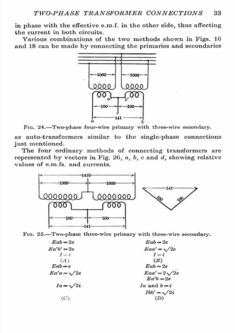
8/11/2019 Transformer Practice 1000194704
http://slidepdf.com/reader/full/transformer-practice-1000194704 45/290
TWO-PHASE
TRANSFORMER
CONNECTIONS
33
in
phase
with the
effective
e.m.f.
in
the
other
side,
thus
affecting
the
current
in both
circuits.
Various
combinations
of
the
two
methods shown
in
Figs.
16
and 18
can
be
made
by
connecting
the
primaries
and
secondaries
B
-1000-
Ismsu
-1000-
ysmsu
mi.-m)
-100- -loo
c
HI
Fig.
24.
Two-phase
four-wire
primary
with
three-wire
secondary.
as
auto-transformers
similar
to
the
single-phase
connections
just
mentioned.
The four
ordinary
methods
of
connecting
transformers
are
represented
by
vectors
in
Fig.
26,
a,
b,
c
and
d,
showing
relative
values
of
e.m.fs.
and
currents.
-1410-
-1000-
-1000-
-100-
-100-
-141-
FiG.
25.
Two-phase
three-wire
primary
with three-wire
secondary.
Eah
= 2e
Eah
=
2e
Ea'h'
=
2e
Eaa'
=
\/2e
Eab='e
Ea'a
=
\/2e
70
=
^/21
(C)
(5)
Eab
= 2e
Eaa' =
2\/2e
Ea'b=2e
la and
h
=
i
766'
=
V2*

8/11/2019 Transformer Practice 1000194704
http://slidepdf.com/reader/full/transformer-practice-1000194704 46/290
34 STATIONARY
TRANSFORMERS
Let
E
=
impressed
volts
per
phase
for
A,
B
and
D.
E
.
e
=
-
impressed voltage
per
phase
for
A,
B and
D.
e
=E
impressed
voltage
per
phase
for C.
I
=i
=
current
per
phase
for A and
B.
Ic
= current
times
\/2
per
phase
for
D.
la',
lb,la,
Ih'
=
\/2
times
the
current
per
phase
for
C.
U)
J,
E
b'
E
(G)
(D)
Fig. 26.
Two-phase
three-,
four-
and
five-wire
systems.
Another
arrangement
is
to
connect
the middles
of
the
two
transformer
secondaries,
s
shown
in
Fig.
27.
This
method
gives
two
main
circuits,
c
and
df,
and four
side
circuits,d,dc,
cf,
and
fa.
The
voltage
of
the
two
main
circuits,
etween
d
and
/is
100,
and
between
a
and
c
is
100.
But the
voltage
across
any
one
of
the
side circuits is
one-half
times
that
in
any
one
of
the
main
circuits,
imes
the
square
root
of
two,
or
50X\/2
=
70
volts.
Another
method
shown
in
Fig.
28,
commonly
called the five-
wire
system,
is
accomplished
by
connecting
the
secondaries
at
the
middle,
similar
to
the
arrangement
in
Fig.
27,
and
bringing
out
an
extra
wire from the
center
of
each
transformer.
The
difference
of
potential
between
a
and
e
will
be
100X\/2
=

8/11/2019 Transformer Practice 1000194704
http://slidepdf.com/reader/full/transformer-practice-1000194704 47/290

8/11/2019 Transformer Practice 1000194704
http://slidepdf.com/reader/full/transformer-practice-1000194704 48/290
36
STATIONARY
TRANSFORMERS
is
effected
by
proportioning
the
windings;
or
one
transformer
may
be wound
for
a
ratio
of
transformation
of
1000
to
50;
the
/3\
j-j.
The
secondary
of
this
transformer
is
connected
to
the middle
of the
secondary
wind-ng
of
the
first.
other
a
ratio
of
1000
to
86.6.
or
A
-1000
H
uKlfMMJ liMiKmJ
B
-1000
H
-75
6'
100-
H
-35-
r25
105.7-
-100-
/
Fig.
29.
Two-phase
multi-wire distribution.
In
Fig.
30,
a c
represents
the
secondary
potential
from
a
to
c
in
one
transformer.
At the
angle
of
90
degrees
to
a c
the
line,
d,
represents
in
direction
and
magnitude
the
voltage
between
c
and
h
of the
other
transformer.
Across the
terminals,
a
c,
ch,
and
a
h,
it
follows
that
three
e.m.fs.
will
exist,
each
differing
in
-1000-
U^imilQj
-1000
liiim^
-50-*i
*
c
'
h-ee.e-^
-100-
FiG.
30.
Two-phase
to
single-phase
distribution.
direction
and
value. The
e.m.f.
across a
is
the
resultant of
that
in
a
c
and
c
6
or
100
volts.
A
complete
list
of
two-phase,
three-
and
four-wire
transformer
connections is
shown in
Fig.
31
and
a
list
of
two-phase parallel
combinations
is
shown
in
Fig.
32.
These
might
or
might
not
represent
a
certain
change
in
the transformer
leads.
They
are,

8/11/2019 Transformer Practice 1000194704
http://slidepdf.com/reader/full/transformer-practice-1000194704 49/290
TWO-PHASE
TRANSFORMER
CONNECTIONS
37
however,
only
intended
to
represent
those connections
and
com-inations
which
can
be made
with
the leads
symmetrically
ocated
on
the
outside
of
the
transformers.
For
grounding
two-phase
systems
several methods
are em-loyed,
the best
being
those
given
in
Fig.
33.
(A)
represents
a
two-phase
four-wire
system,
the
two
single-
phases
being
independently
operated,
consequently
two
inde-endent
grounds
are
necessary.
(3)
h
^
B
U\aaaI
(4).
pq
f^'^
C^
PA
5
(6)
v5
1
fA
-e-v^-
FiG.
31.
Complete
list
of
two-phase
transformer
connections.
B
(B)
also
represents
a
two-phase
four-wire
system
to
be
used
for
three-phase
and
two-phase
at
the
same
time.
This is similar
to
the
Taylor
system
excepting
that
two
units instead of
three
are
employed.
The
maximum
voltage
to
ground
is
a'
x,
or
i ;x
0.866.
(C)
likewise
represents
a
two-phase
four-wire
system
with
T
three-phase
primary.
In this
case
the
maximum
voltage
I
strain
to
ground
is
E^/
of
voltage
between
terminals
(D)
represents
a
two-phase
three-wire
system.
The
maximum
strain
to
ground
in this
case
is
full
voltage
of
any
phase.

8/11/2019 Transformer Practice 1000194704
http://slidepdf.com/reader/full/transformer-practice-1000194704 50/290
38
STATIONARY TRANSFORMERS
{E)
represents
a
V
two
unit
system.
The
maximum
voltage
strain to
ground
is
E
0.866,
or
the
same
as
(B)
.
{F)
represents
the
two-phase
interconnected
four-
or
five-wire
A
B
A
I
B
(5)
B
A
B
IWSAl
(9)
B
^A/^/J
INAAN
a
6
a
6
r'^^ c^^ ^
V~^^
C2X^
nr^
1 ^^
^
r^
,^
A^
A^
^^
AA AA
a
b
a
b
A
WvaaI
Iwv^
Uaaa
(H)
AA
/^s/\
AA^^^^AA
b
Fig.
32.
Two-phase parallel
combinations.
system.
The
maximum
voltage
strain
to
ground
is
50
per
cent,
of
any
phase
voltage
and
the
voltage
across
any
two-phase
terminals
is
70.7
per
cent,
of
full-phase
voltage.

8/11/2019 Transformer Practice 1000194704
http://slidepdf.com/reader/full/transformer-practice-1000194704 51/290
CHAPTER IV
THREE-PHASE
TRANSFORMATION
SYSTEM
General
Principles.
In
considering
the
question
of
three-phase
transformation
we
have
to
deal
with
three
alternating
e.m.fs. and
currents
differing
in
phase
by
120
degrees,
as
shown
in
Fig.
34.
One e.m.f. is
represented
by
the
line,
A
B,
another
by
the
line,
B
C,
and the
third
by
the
line,
C A. These
three e.m.fs.
a
\
1
/' ^^
2
(i )b
Fig.
33.
Methods of
grounding two-phase
systems.
and
currents
may
be
carried
to
three
independent
circuits
requiring
six
wires,
or a
neutral
wire, or common
return
wire
may
be
used,
where
the three ends
are
joined
together
at
x.
The
e.m.f.
phase
relations
are
represented
diagrammatically
by
the
lines,
ax,
b
x,
and
c
x;
also,
A
B,
B
C,
and
C
A. The
arrows
only
indicate
the
positive
directions in the
mains and
through
39

8/11/2019 Transformer Practice 1000194704
http://slidepdf.com/reader/full/transformer-practice-1000194704 52/290
40
ST A TIONA
R Y
TEA
NSFORMERS
the
windings;
this
direction is
chosen
arbitrarily,
herefore,
it
must
be remembered
that
these
arrows
represent
not
the
actual
direction
of
the
e.m.fs.
or
currents at
any
given
instant,
but
merely
the
directions
of
the
positive
e.m.fs.
or
currents
i.e.,
the
positive
direction
through
the
circuit.
Thus,
in
Fig.
32a
the
e.m.fs.
or
currents
are
considered
positive
when
directed
from
the
common
junction
x
toward
the
ends,
ah
c.
In
passingthrough
the
windings
from
a
to
h,
which
isthe direc-ion
in which
an
e.m.f.
must
be
generated
to
give
an
e.m.f.
acting
upon
a
receiving
circuit
from main
a
to
main
h,
the
winding,
a,
Fig. 34.
Graphic
representation
of
three-phase
currents
and e.m.fs.
is
passed
through
in
a
positive
direction,
and the
winding,
6,
is
passed
through
in
a
negative
direction;similarly
the e.m.f. from
b
to
c,
and the
e.m.f. from
main
c
to
a.
The e.m.f. between
a
and
b
is
30
degrees
behind
a
in
time-phase,
and
its
effective
value
is
(14)
E
cos
30
=
^3
E;
where
E
is
the value of
each of
the
e.m.fs.
a
b,
and
c.
With this
connection
the
e.m.f.
between
any
two
leads,ab,b
c,
or a
c,
is
equal
to
the e.m.f.
in
each
winding,
a
x,b
x,ov
ex
multi-lied
by
the
square
root
of
three.
For
current
relations
we
see
in
Fig.
34
that
a
positive
current
in
winding
1
produces
a
positive
current
in
main
A,
and
that
a
negative
current
in
winding
2
produces
a
positive
current
in
main
A
;
therefore,
the
instantaneous
value
of
the
current
in
main

8/11/2019 Transformer Practice 1000194704
http://slidepdf.com/reader/full/transformer-practice-1000194704 53/290
THREE-PHASE TRANSFORMATION
SYSTEM
41
A
is
I1
I2,
where
I^
is
the
current
in
winding
1,
and
1
2
is
the
current
in
winding
2.
Similarly,
he
instantaneous
value
of
the
current
in main
B
is
/j
^3,
and
in main
C,
it
is
I^
I^.
The
mean
effective
current
in main
A
is
30
degrees
behind
7^
in
phase;
and
its
effective
value
is
the
square
root
of
three
times
the
current
in
any
of
the
different
phases;
so
that
with this connection
the
current
in
each
main is
the
square
root
of
three
times
the
current
in
each
winding.
When the
three
receiving
circuits
ah
c
are
equal
in
resistance
and
reactance,
the three
currents
are
equal;
and each
lags
behind
its
e.m.f.,ah,h
c,
and
a
c,
by
the
same
amount,
and all
are
120
time-degreesapart.
The
arrangement
shown
in
Fig.
34, by
the
lines,
a,
h,
and
c,
is
called
the Y
or
star
connection
of
transformers.
Each
of
these
windings
has
one
end connected
to
a
neutral
point,
x;
the
three
remaining
ends,
ah
c,
commonly
called
the
receiving
ends,
are
connected
to
the
mains.
The e.m.f.
between
the
ends,
or
terminals
of
each
receiving
circuit is
equal
to
\/3
E,
where
E
is
the e.m.f. between
ax,
h
x,
and
c
x.
The
current
in each
receiving
circuit
is
equal
to
the current
in
the
mains,
ah
c.
The
resistance
per
phase
cannot
be measured
directly
etween
terminals,
since
there
are
two
windings,
or
phases
in series.
Assuming
that
all
the
phases
are
alike,
the
resistance
per
phase
ir,
one-half
the
resistance
between
terminals.
Should the
resist-nces
of
the
phases
be
equal,
the
resistance of
any
phase
may
be
measured
as
follows:
The
resistance
between
terminals
a
6
is
:
Resistance
of
a
h
=
R^
+
Ri.
The
resistance
between
terminals 6
c
is:
Resistance
of
b
c
R^-^-R^.
The
resistance
between
terminals
a c
is:
Resistance of
a C
R3+R2.
Therefore
:
_,
Res.
a
b
Res.
b
c-|-Res.
a
c
R3=
2
'
_,
Res. 6
c
Res.
a
c
-j-
Res.
o
6
,, ^.
^i
2
'
(15)
^r,
Res.
a c
Res.
a
6
-|-Res.
b
c
R,
2
'

8/11/2019 Transformer Practice 1000194704
http://slidepdf.com/reader/full/transformer-practice-1000194704 54/290
42
STATIONARY
TRANSFORMERS
The
method
of
connectingthree-phase
circuits
shown
in
Fig.34,
where the
windings,
1,
2
and
3,
are
connected
in
series
a,t
A,
B
and
C,
is
called the delta
connection.
In
this connection
the
e.m.f.
on
the
receiving
circuit
is the
same
as
that
on
the
mains;
and the
current
on
each
receiving
circuit is
equal
to
\/3
times
that
in
any
winding,
or
\/3I,
where
/
is
the
current
in
1,2,
or
3-
Assuming
that
all
phases
are
alike,
the
resistance
per
phase
is
3
equal
to
the
ratio
of
3
to
2
times
^
the
resistance between A and
B. In
a
delta connection there
are
two
circuits
between A and
C,
one
through phase
1,
and the other
through phases
2
and 3
in
series.
From
the
law of
divided circuits
we
have the
joint
resistance
to
two
or more
circuits in
parallel
is
the
reciprocal
of
the
sum
of the
reciprocals
f
the
resistances
of
the several
branches.
37?
Hence,
-^
is
the
resistance
per
phase
R
being
the
resistance
of
one
winding
with
two
others
in
parallel.
The
ohmic
drop
from
terminal
to
terminal with
current
/ in
the
line,
is
3
Ohmic
drop
=
2/X-R.
(16)
To
transform
three-phase
alternating
current
a
number
of
different
ways
are
employed.
Several
of
the
arrangements
are:
1.
Three
single-phase
transformers
connected
in
star
or
in
delta.
2.
Two
single-phase
transformers
connected
in
open-delta
or
in
tee.
3.
One
three-phase
transformer
connected
in
star
or
in
delta.
With
three
single-phase
transformers
the
magnetic
fluxes
in
the
three
transformers
differ in
phase
by
120
time-degrees.
With
two
single-phase
transformers
the
magnetic
fluxes
in
them differ in
time-phase by
120
degrees
or
by
90
degrees
accord-ng
to
the
connection
employed.
With
the
three-phase
transformer
there
are
three
magnetic
fluxes
differing
n
time-phase by
120
degrees.
The
single-phase
transformer
weighs
about
25
per
cent,
less
than
three
separate
transformers
having
the
same
total
rating;
its
losses
at
full
load
are
also about
25
per
cent.
less.
Two
separate
transformers,
V-connected,
weigh
about
the
same
as
three
single-phase
ransformers
for
the
same
power
transmitted
;
the
losses
are
also
equal.

8/11/2019 Transformer Practice 1000194704
http://slidepdf.com/reader/full/transformer-practice-1000194704 55/290

8/11/2019 Transformer Practice 1000194704
http://slidepdf.com/reader/full/transformer-practice-1000194704 56/290
44
STATIONARY
TRANSFORMERS
three
single-phase
ransformers that
may
be
employed
for
obtain-ng
the
same
service
are
frequently
discussed
on
the
basis
of the
decrease
in
cost
of
the
several
types
of
transformers with
increase
in
rating;
and
on
such
basis
it
has
been
shown
that
the
three-
phase
transformer
is
the
cheaper,
while
the
other
combinations
are
more
expensive
on
account
of
requiring
an
equal
or
greater
aggregate
rating
in
smaller
transformers.
It
should,
how-ver,
be
borne
in
mind
that
a
three-phase
transformer
is
not,
generally
speaking,
so
efficient
as a
single-phase
transformer
designed
along
the
same
lines
and
wound
for
the
same
total
output.
Fig.
36.
Vector
sum
of
effective
e.m.fs.
It
is
shown
very
clearly
in
Fig.
35
that
a
connection
across
the
terminals,
B
C,
x
E,
and
x
D,
will
receive
a
voltage
which
is
the
resultant of
two
e.m.fs.
differing
in
time-phase by
120
degrees;
or
the
result
from
adding
the
e.m.fs.
of
E^
and
E^
at
60
degrees,
which
is
equivalent
to
E^ \/3.
It
is
shown
in
Fig.
36,
where
one
phase
of
a
star-connected
group
of transformers is
reversed,
the resultant
e.m.f.,
x'
y'
and
X
y,
is
equivalent
to
the
component
e.m.fs.,
x
c',
x
a'
and
X
b,
X
a;
consequently
the
resultant
of
all
three
e.m.fs.
is
zero.
This is
in
accordance
with
Kirchhoff's
law which
states
that
where
an alternating-current
ircuit
branches,
the effective
current
in
the
main
circuit
is
the
geometric,
r
vector
sum
of
the
effective
currents
in
the
separate
branches.
The
modifications
of
the
fundamental
laws
appertaining
to
this
are
discussed
in
many
books
treating
alternating
currents
in
theory,
and
the
summary
given
here
is
for
the
purpose
of
comparison.
However,

8/11/2019 Transformer Practice 1000194704
http://slidepdf.com/reader/full/transformer-practice-1000194704 57/290
THREE-PHASE
TRANSFORMATION
SYSTEM
45
it
is noted
in
Fig.
36
that the
phase
relations
between o'
and
b',
b'
and
c',
and
c
and
b
and
c
have
been
changed
from
120
degrees
to
60
degrees
by
reversing
phases
b' and
c.
The
pressure
between
a
and
b
and
o'
and
c'
is
'
\/S,
showing
their
phase
relations
to be
unchanged.
For
example,
in
Fig.
36,
considering
only secondary
coils
of
three
single-phase
transformers
that
are
supposed
to
be
connected
in
star,
but
as a
matter
of fact
connected
as
shown,
let
us
assume
that E is
equal
to
100
volts:
(a)
What will be the
voltage
between terminals of
Ea,
E/,
and
Ea, Eb,
and
Ee
phases?
(b)
What
will
be
the
voltage
between
terminals
a' and
c',
and
a
and
6?
(c)
What
will
be
the
voltage
across
a'
y'
and
y' c\
also
a
y
and
y
6?
(a)
The
voltage
acting
on
any
of
these
windings
is
equal
to
E
v/3
100X\/3
=
173.2
volts.
The
voltage acting
on Ea
,
Eb',
etc.,
is
Ea
;^
X
173.2=0.577
X
173.2=
100
volts.
v3
(b)
The
voltage
between
terminals
a' and
c',
r a
and
b,
is
equal
to
\/3
times the
voltage
acting
on
Ea-
etc.,
or
E\/3=
100
X
173.2= 173.2
volts.
(c)
It
is
evident
that
the
two
e.m.fs.,
a' x'
and
c'
x'
,
are
equivalent
to
their
resultant,
y'
x'
,
which
is
equal
and
opposite
to
b'
x'
;
the dotted
lines,
'
y'
and
y'c',
re
equal
to
Ea
,
Eb'
,
etc.,
at
120
degrees
apart;
in other
words,
1
E
=
a
y',eic.,=
-X173.2
Vo
= 0.577X173.2
= 100
volts.
In
Fig.
37
in
shown
a
diagram
of
three-phase
currents
in which
X,
y,
z
are
equal
and
120
degrees
apart,
the
currents
in the
leads,
o,
6,
c,
are
120
degrees
apart
and
each
equal
to
\/3
times
the
cur-ent
in each of the
three
circuits
X,
Y and
Z.

8/11/2019 Transformer Practice 1000194704
http://slidepdf.com/reader/full/transformer-practice-1000194704 58/290
46
ST
A
TIONA
R
Y
TRA
NSFORMERS
The
current
in
each
lead
is
shown
made
up
of
two
equal
compo-ents
which
are
60
degrees
apart.
As
an
example
showing
the
use
of
Fig.
35,
assume
a
circuit,
f
three
single-phase
ransformers
delta-connected.
What
will
be
the
r
0
Fig.
37.
Geometric
sum
of
three-phase
currents.
Fig.
38.
Geometric
sum
of
e.m.fs.
at
any
instant
equal
to
zero.
current
through
X-phase
winding
if
the
current
in h
lead
is
500
amperes?
Since
one
component,
X,
has
in
the
lead
the
same sign
as
it
has

8/11/2019 Transformer Practice 1000194704
http://slidepdf.com/reader/full/transformer-practice-1000194704 59/290
THREE-PHASE
TRANSFORMATION
SYSTEM
47
in its
own
transformer
winding,
and
the
other
component, Y,
has
in
the
lead the
opposite
sign
to
that
which it
has
in
its
own
trans-ormer
winding,
X,
is
represented
in
lead
by
the
same
vector
as
in
its
own
transformer
winding;
while
the other
component,
F,
is
represented
in
the
lead
by
a
vector
180
degrees
from that which
represents
it in
its
own
circuit,
herefore,
X
=~^
500.
v3
The
instantaneous values
of the
currents
in
any
one
wire
of
a
three-phase system
are
equal
and
opposite
to
the
algebraic
sum
of
the
currents
in
the other
two
sides.
Therefore,
the
algebraic
sum
of e.m.fs.
or
currents at
any
instant is
equal
to
zero.
This
fact
is
shown in
Fig.
38,
the
geometric
sum
of
the
three
lines,
A,
B,C,
being
equal
to
zero
at
any
instant.
Single-phase
transformers
may
be
connected to
a
three-phase
system
in
any
of
the
following
methods:
Delta-star
group
with
a
delta-star.
Star-star
group
with
a
star-star.
Delta-delta
group
with
a
delta-delta.
Star-delta
group
with
a
star-delta.
Delta-star
group
with
a
star-delta.
Delta-delta
group
with
a
star-star.
It
must,
however,
be
remembered that
it is
impossible
to
connect
the
following
combinations,
because the
displacement
of
phases
which
occurs,
when
an
attempt
is made
to connect
the
secondaries,
ill result in
a
partial
short-circuit.
Delta-star
with
a
star-star.
Delta-delta
with
a
star-delta.
Delta-star
with
a
delta-delta.
Star-delta
with
a
star-star.
As
is
well
known
there
are
four
ways
in which
three
single-
phase
transformers
may
be
connected between
primary
and
secondary three-phase
circuits. The
arrangements
may
be
described
as
the
delta-delta,
tar-star,
star-delta,
nd
delta-star.
In
winding
transformers for
high
voltage
the
star
connection
has
the
advantage
of
reducing
the
voltage
on an
individual
unit,
thus
permitting
a
reduction in
the number
of
turns
and
an
increase in
the
size
of
the
conductors,
making
the
coils easier
to
wind
and
easier
to
insulate.
The delta-delta
connection
never-heless
has
a
probable
advantage
over
the star-delta
arrangement,
in
that
if
one
transformer
of
a
group
of
three
should become
disabled,
the
two
remaining
ones
will continue
to
deliver
three-

8/11/2019 Transformer Practice 1000194704
http://slidepdf.com/reader/full/transformer-practice-1000194704 60/290

8/11/2019 Transformer Practice 1000194704
http://slidepdf.com/reader/full/transformer-practice-1000194704 61/290
THREE-PHASE
TRANSFORMATION
SYSTEM
49
former.
The
line
current is
\/3
times
that
in
each
transformer
winding,
or
a/3X
57.7
=
100
amperes,
therefore
the
current
in
each
phase
is
100
X
-y^
=
57.7
amperes.
The
output
being
a/3
E I-
Cos d
=
1.
732
X
1,
000
X
100
X.7
1
=
123
kw.
approx.
In the
star-star
arrangement
each
transformer
has
one
terminal
connected
to
a common
junction,
or
neutral
point;
the three
remaining
ends
are
connected
to
the
three-phase
mains.
The
number of
turns
in
a
transformer
winding
for
star
connec-ion
is
57.7
per
cent,
of that
required
for
delta connection
and the
-1000-
-1000-
h
677
^
H
577
^
-1000-
577-
-67.7-
rron
57.7
immMj
-MO-
nnjn
^57.7-
-100-
100
Fig.
40.
Star-star
connection
of transformers.
cross-section
of
the conductors
must
be
correspondingly
reater
for
the
same
output.
The
star
connection
requires
the
use
of
three
transformers,
and
if
anything
goes
wrong
with
one
of
them,
the
whole
group
might
become
disabled.
The
arrangement
shown in
Fig.
40
is
known
as
the
star
or
Y
system,
and
is
especially
onvenient
and
economical
in
distributing
ystems,
in
that
a
fourth
wire
may
be
led
from
the
neutral
point
of
the three
secondaries.
The
voltage
between the neutral
point
and
any
one
of
the
outside
wires is
^
of
he
voltage
between
the
outside
wires,
namely
V3
1000
X-7-
=
1,000X0.577
=
577
volts.
The
current
in
each
phase
of
a
star-connected
group
of
trans-ormers
is
the
same as
that
in
the
mains.
Fig.
41 shows
a
star-star
connection
in which
one
of
the
4

8/11/2019 Transformer Practice 1000194704
http://slidepdf.com/reader/full/transformer-practice-1000194704 62/290
50
ST
A
TIONARY
TRANSFORMERS
secondary windings
is
reversed.
It
may
be
noted
that
the
phase
relations
of
phase
c
have
changed
the
relations
of
a
c
and
b
c
from
120
degrees
to
60
degrees
by
the
reversal
of
one
transformer
connection.
The
resultant
e.m.fs.,
ac
and
be,
are
each
^
=
^3
-1000
-1000-
UWUq^
1000-
mw
Fig.
41.
Star-star
connection
of
transformers,
one-phase
reversed.
57.7,
but
in
reality
should
be
1
00
volts
the
voltage
between
a
and
b
is
57.7
X\/3
=
100. In
star-connecting
three
single-phase
trans-ormers
it is
quite possible
to
have
one
of the
transformers
reversed
as
shown.
-577-
UM^M^ IM2MMJ
Fig. 42.
Star-delta
connections of transformers.
In
the
star-delta
arrangement
shown in
Fig.
42
the
ratio
of
transformation
is
;^'
or
0.577
times
the
ratio
of
secondary
to
\/3
primary
turns,
and the e.m.f.
acting
on
each
secondary
circuit
is
the
same as
that between the
mains.

8/11/2019 Transformer Practice 1000194704
http://slidepdf.com/reader/full/transformer-practice-1000194704 63/290

8/11/2019 Transformer Practice 1000194704
http://slidepdf.com/reader/full/transformer-practice-1000194704 64/290
52
ST
A
TIONA
R
Y
TRA
NSFORMERS
that
each
transformer
need be
wound for
only
57.7
per
cent.,
of
the
voltage
on
the
mains.
In
the
arrangement,
commonly
called
V
or
open-delta
the
voltage
across
the
open
ends
of
two
transformers
is
the
resultant of the
voltages
of
the
other
two
phases;
see
Fig.
44.
This
method
requires
about
16
per
cent,
more
transformer
capac-ty
than
any
of the
previous
three-phase
transformations
shown,
assuming
the
saijie
efficiency
f
transformation,
heating,
and
total
power
transformed.
B
I
-1000-
-1000-
1000-
-1000-
-1000-
^100-
mmmJ
KO
Fig.
45.
V
connection
of transformers with
secondary
windings
connected
in
opposite
directions.
In
comparing
the kv-a
capacity
of
two
single-phase
rans-ormers
connected
in
open
delta,
with
three
similar
transformers
connected
in
delta,
the
kv-a
capacity
is
approximately
1
-^
^^
=
58
per
cent.
This is
due
to
the
fact that
for
the
delta connection
the
current
and
voltage
of each
transformer
are
in
phase
with
each
other,
while
for
the
open-delta
connection
the
current
and
voltage
of each
transformer
are
30
degrees
out
of
phase
with
each
other.
With
the
open-delta
method
a
slight
unbalancing
may
exist,
due
to
the different
impedances
in
the
middle
main
and the
two
outside
mains,
the
impedance
in
the
middle
main
being
the
algebraic
sum
of
the
impedances
in
the
two
outside mains.
The
open-delta
arrangement,
(where
the
primary
is
connected
like
that
shown
in
Fig.
45)
is
in
every
respect
equivalent
to
the
open-delta
connection
represented
in
Fig.
42.
The
primaries
are
connected in
a
reverse
direction,
r
180
degrees
apart
in
phase
with
the
secondary.

8/11/2019 Transformer Practice 1000194704
http://slidepdf.com/reader/full/transformer-practice-1000194704 65/290
THREE-PHASE
TRANSFORMATION
SYSTEM
53
The
vector
diagram
shows the
changed
phase
relations of
primary
to
secondary. By
connecting
two
single-phase
rans-ormers
in
the
oppositedirection,
hat
is
to
say,
connecting
the
secondary
like
that
of
the
primary,
and the
primary
like
that
of
the
secondary,
we
obtain
the
same
transformation
characteristics.
Like
that of
the
open-delta
arrangement
the
tee
method
requires
only
two
single-phase
transformers.
As
regards
the
cost
of
equipment
and
the
e^ciency
in
opera-ion
the
tee
arrangement
is
equal
to
either
the
open-delta,
the
star
or
the
delta methods.
The
tee
arrangement
is
represented
in
Fig.
46.
The
end
of
one
transformer
is
connected
to
the
middle of
the
other.
w
-100-
-100
-100-
.^ ^
60^
X
86.6
-^0
s^
Fig. 46.
Tee
or
T connection of transformers.
The
number
of
turns
on a
6 is
^
=1.16
times
the number
of
v3
turns
on
x c.
Its
ability
o
maintain
balanced
phase
relations
is
no
better
than
the
open-delta
arrangement,
and
in
no
case
is
it
preferable
to
either
the
star
or
delta methods of
connecting
three
single-phase
ransformers.
It
is
worthy
of
note
that
the transformer
which
has
one
end
tapped
to
the
middle
of
the
other transformer
need
not
be
designed
for
exactly
^^^
86.6
per
cent,
of the
voltage;
the
normal
volt-
age
of
one
can
be
90
per
cent,
of
the
other,
without
producing
det-imental
results.
Another
three-phase
combination
is
shown
in
Fig.
47. In
this
case
it is
assumed that
the three
single-phase
transformers
were
originally
onnected
in
star
at
oA,
oB
and
oC
as
shown
by
dotted
line
in
the
vector
diagram.

8/11/2019 Transformer Practice 1000194704
http://slidepdf.com/reader/full/transformer-practice-1000194704 66/290
54
STATIONARY
TRANSFORMERS
To
change
the
transformation
to
the
combined
system
of
the
star-delta,
he
end
of
winding
oB
is
connected
with
the
point
o'
of the
phase oA,
and the
end 0
of the
phase
oC
with
the
point
o of the
phase
oB
so
that the
vector
oB
becomes
o'E'
and
oC
becomes
o C'. The
length
of
the three
vectors
is
proportional
to
the number of coils
per
phase,
all
coils
having
the
same num-
mum
Kwwwl
rmtm
f fc
iX\
ca
-E
-E-,
^^
Fig.
4 .
Delta
connection
with
50
per
cent,
of
winding
reversed to
obtain
another
phase
relation
for
maximum
voltage.
ber of
turns.
The end
o
of
phase
oA
is
connected
to
the
point
of the
phase
o C\
Going
over
the
list
of
common three-phase
connections
we
find
there
are
only
four
delta-delta
systems
in
common
use,
these
being
shown
in
Fig.
48.
Q
kit]
Uj
Q-O
n
Fig.
48.
Common
delta
connections.
These,
and
a
combination of
them
may
be
so
arranged
as
to
give
not
less than
sixteen different
changes;
all these
changes
being given
in
Fig.
49.
Taking
away
one
transformer of
each
of
the above
combina-ions
we
find
open-delta
connections
like
those
given
in
Fig.
50.
On
carefully
looking
over
the
eighteen
different delta-delta
combinations
given
in
the above
figures,
t will
be noted that the
first
ten
represent
changes
of
one or
two
of
the transformers while

8/11/2019 Transformer Practice 1000194704
http://slidepdf.com/reader/full/transformer-practice-1000194704 67/290
THREE-PHASE TRANSFORMATION
SYSTEM
55
the
remaining
eight
have all
their secondaries
connected in
a
direction
opposite
to
their
respectiveprimary windings.
There
are
also four
common
star-star
connections in
general
use,
these
being
shown in
Fig.
51.
Like
the
delta-delta,
hese four
star-star
connections
can
be
arranged
to
give
sixteen different combinations
as
will
be
seen
from
Fig.
52.
Continuing
further
through
the
series
of
three-phase
connec-ions
we
come
to
delta-star
or
star-delta
combinations.
The
star-delta and
delta-star
in
common
use are
given
in
Fig.
53.
iL
ijj
ij
b=ur4i
lAIAj
uAi'u
LninJ
crtru
m
f=^
f^
w^
f^
w
I
Jyi
cyp^
^^^#t^
^Yh^
^\^ ^Y^\^
^^YJY^
Cld~VP
n.^iH CY?T^
Fig.
49.
Uncommon
delta
connections.
The
uncommon systems
of
star-delta
transformer
connections
are
shown
in
Fig.
54.
These
may
be
changed
about
to
delta-
star
as
desired,
hus
making
twice
the
number. It
must
be
re-embered,
however,
that
none
of
them
can
be
changed
about
from
one
set
of
combinations
to
another.
POLARITY
IN
THREE-PHASE
TRANSFORMER
CONNECTIONS
It
is
customary
for all
transformer
manufacturers
to
arrange
transformer
windings
so
that left-
and
right-hand
primary
and
secondary
leads
are
located the
same
for all classes
and
types.
It
is
not, however, customary
for
operating
companies
and others
to
do
so
after
a
transformer has
been
pulled
to
pieces.
The
major-ty
seems
to
follow manufacturer's
prints
and
wiring
diagrams
of
transformer
connections
coming
from
the
factory,
all
of
which
are
assumed
to
have
the
same
relative
direction of
primary
and

8/11/2019 Transformer Practice 1000194704
http://slidepdf.com/reader/full/transformer-practice-1000194704 68/290
56
STATIONARY
TRANSFORMERS
secondary
windings,
thus
permitting
similarly
located
leads
leav-ng
the
transformer tank
to
be connected
together
for
parallel
operation
if
desired without
the
necessity
of
finding
the
polarity.
Large
and
moderate-sized
high-voltage
transformers
are
rarely
used
for
single-phase
ervice.
They
may
be of
single
or
three-
phase
design
but
they
are
used
almost
exclusively
on
three-phase
systems,
and
connected
in
star
or
delta
or a
combination
of
the
^
W
U-b
b^
d-\j
LrSj
rvp
rvi
rv^ ^T^ ^Vt^
P^
Fig.
50.
Uncommon
open-delta
connections.
two
methods.
Single-phase
nits in
large
and
medium and
small
sizes
(6000
to
0.5
kv-a)
are
very
common.
They
afford
a
better
opportunity
for
different
polarities
han
three-phase
units,
which
are
also
made
in
large
and
medium
and
small
sizes
(14,000
to
1.0
kv-a).
The delta and
star
methods of
connections
generally
referred
to
as
conventional
are
understood
to
have
all
the
primary
and
secondary windings
wound
in
opposite
directions around
uJ
u
kJ
u
uJ
uJ
Urrzi
b::^ Lj
I
i
I
i
cri_rn_r|p
p
p
n
rj
n
|n_pi_p
Fig.
51.
Common
star
connections.
the
core.
This conventional
method
is
not
always
followed
as
problems
arise in
every-day
practiceshowing
that it is
not
always
carried
out.
Three
single-phase
transformers
or
one
three-phase
trans-ormer
may
have
their
windings
arranged
in
the
following
manner:
(1)
The three
primary
and
secondary
windings
wound
in
the
same
direction
positive
direction.
(2)
The
three
primary
and
secondary
windings
wound
in the
same
direction
negative
direction.

8/11/2019 Transformer Practice 1000194704
http://slidepdf.com/reader/full/transformer-practice-1000194704 69/290
THREE-PHASE
TRANSFORMATION
SYSTEM
57
(3)
The three
primary
windings
wound
in
opposite
direction
to
the
secondary
windings
positive
direction.
(4)
The
three
primary
windings
wound
in
opposite
direction
to
the
secondary
windings
negative
direction.
(5)
One
primary
winding
of
the
group
of
three
may
be wound
opposite
to the
remaining
two
primaries
and the
three
secondaries
positive
irection.
J
d
u
u
u
u
u
J
u
uuii
L
u
u
cHx-J
n
r| p
n
q
n
p
rj
n
^^-p-n
H
pi
^
fhR-P
Lrbrb LrhnJ
L
b
u
Lrd-J
J
f
J
u u
u
L
(rjJrL_r r̂j
n
p_p_p
n
p
p
r\-p-n
n
r|
n
LrrhJ
JUL
J
L
J
Uxra
r^
p p
r^-p_o p
rj
p
n
p
n
Fig.
52.
Uncommon
star
connections.
(6)
One
primary
winding
of
the
group
of
three
may
be wound
opposite
to
any
of
the
remaining
two
primaries
and the
three
secondaries
negative
direction.
(7)
Two
primary windings
of
the
group
of
three
may
be
wound
opposite
to
the
one
remaining primary
and three
secondary
windings
positive
direction.
WwJ k/wJ Vf*i W^
WmI
IwmJ
UwJ
Ivwl Iwyj
Ivwl kwj M*\
ry^ ^ (:^i_iq_r|
^i-^
^
n
n
n
Fig.
53.
Ck)mmon star-delta
connections.
(8)
Two
primary windings
of
the
group
of
three
may
be
wound
opposite
to
the
one
remaining primary
and
the
three
secondary windings negative
direction.
(9)
One
unit
may
have its
primary
and
secondary
windings
different
to
the
two
remaining
units,
as:
(a)
The
unit
on
the left
positive
direction.
(6)
The
center
unit
positive
direction.
(c)
The
unit
on
the
right positive
direction.

8/11/2019 Transformer Practice 1000194704
http://slidepdf.com/reader/full/transformer-practice-1000194704 70/290
58
STATIONARY
TRANSFORMERS
(10)
One unit
may
have
its
primary
but
not
the
secondary
windings
different
to
the
remaining
two
units,
as
(9)
but
in
the
negative
direction.
(11)
Two
units
may
have
their
primary
and
secondary
wind-ngs
different
to
the
remaining
unit,
as:
(a)
The
left
and
center
units
positive
direction.
(b)
The
right
and
center
units
positive
direction.
(c)
The
left
and
right
units
positive
direction.
(12)
Two
units
may
have
their
primary
but
not
secondary
windings
different to
the
one
remaining
unit,
as
(11)
but
in
the
negative
direction.
U^
U/w
Iv\aI
rp
PL_n
a
U/sJ U/vJ Iv a|
U/s/J
U^
l\/\A
ryen
U/M U/vJ IwAl
Iwj
IwJ
L/j
Lj
L/J
u/J
/
iJj
uJ
iL
\it--LLr-\h
uil
uj
lij
U-rHljriwJ
^
nnn
n
p
n
,
I
I
I,
U/SaI
P^VsI
I/WM
UvvrhJ^*lvvg
'
Uv/J
'
LvUrh
I
1^^
i*^^
i'^'*^ f*^
1*^^
('^^
Fig. 54.
Uncommon star-delta
connections.
Transformers
of
the
same
rating
and
of
the
same
make
are as a
rule
assumed to
have the
same
polarity,
impedance
and
ratio
of
transformation.
In
all
cases
where
transformers
are
not
of
the
same
make
it
is
advisable
that the
secondary
connections
be
subjected
to
polarity
tests
before
connecting
them in
delta
or
star.
The
mistakes
which
can
be
made,
are:
(1)
One
or
more
reverse windings.
(2)
Internal
leads
crossed.
(3)
Where
transformers
are
located
some
distance
apart,

8/11/2019 Transformer Practice 1000194704
http://slidepdf.com/reader/full/transformer-practice-1000194704 71/290

8/11/2019 Transformer Practice 1000194704
http://slidepdf.com/reader/full/transformer-practice-1000194704 72/290
60
STATIONARY
TRANSFORMERS
and where connections
are
made
at
some
distance,
the
leads
may
become
crossed.
The
reversal of
two
leads
of
either
the
primary
or
secondary
will
reverse
the
polarity,
this
being
(so
far
as
the
external
connec-ions
are
concerned)
the
same
as
reversing
one
winding.
Reversing
the
line
leads
of
a
star-star,
delta-delta,
tar-delta
or
delta-star
will
not
reverse
the
polarity
since
the
transformer
leads
themselves
must
be
changed
in order
to
make
the
change
in
polarity.
This
should
be
particularly
oted when
parallel
^
Time-Phase
Angle
Primary Windings'
Secondary
Windings
Fig.
57.
Complete
cycle
of
polarity
changes.
operation
is
desired,
or,
though
the
phase
relations
of
two trans-ormer
groups
may
be the
same
paralleloperation
might
be
impos-ible
(see
Fig.
55)
.
The
effect of
a
reversal
of
one
or
two
primary windings
is
not
the
same
for
the four
systems
of
star
and
delta,
but
is
:
For
Star-star:
The
reversal
of
one or
two
primary
windings
will
not
produce
a
short-circuit,
ut
will
produce
a
difference in
phase
relations
and
voltages.
The
maximum
voltage
will
not
be
greater
than the
line
voltage
(see
Fig.
58).
For Delta-delta:
The reversal of
one
or
two
primary windings
will
immediately
produce
a
short-circuit
when the
secondary

8/11/2019 Transformer Practice 1000194704
http://slidepdf.com/reader/full/transformer-practice-1000194704 73/290
THREE-PHASE
TRANSFORMATION
SYSTEM
61
delta
is
closed.
The maximum
voltage
difference
will
be 2E
or
double-line
voltage
(see
Figs.
59
and
60).
For
Star-delta:
The
reversal
of
one or
two
primary
windings
will
immediately produce
a
short-circuit
when the
secondary
delta
is closed.
The
maximum
voltage
difference
at
that
point
which
closes
the
delta
will
be 2E
or
double-line
voltage.
Reveraed
a-
A
(b)
Opposite
polarity
B-b
a-
A
Reversed
Fig.
58.
Three-phase
polarity
difficulties.
For
Delta-star:
The
reversal of
one or
two
primary
windings
will
not
produce
a
short-circuit
on
the
secondary
side
when the
star
is
made.
The
maximum
voltage
difference
will
be
E
or
line
voltage,
but
voltages
and
phase
relations will
be
unequal.
The
thick,
black lines
shown
in
Figs.
55,
56,
57,
58,
59
and
60
represent
secondary
windings.
Fig.
57
gives
all
the
possible
tar
and
delta
polarity
combina-ions,
or,
sixteen
as
already
explained.

8/11/2019 Transformer Practice 1000194704
http://slidepdf.com/reader/full/transformer-practice-1000194704 74/290
62
STATIONARY TRANSFORMERS
Wrong
Connection
Correct
Connection
JvvA/V-i-A/WV
LAA^AJ
Reversed
J'^N/'X-,.
'z?
^
a
(a)
n
2E
^
(a)
e
,*,
e
a-b-c
.A.
kvvAl
^v^^N
l^/vv^|
6
A-B-C
E
B-C-A
a-A-B
i?
Vi__:
arr
'
-2E
H
Z
AC
K'SA,^ UaaaI IvvvJ/
(J
Fig. 59.
Three-phase
polarity
difficulties.

8/11/2019 Transformer Practice 1000194704
http://slidepdf.com/reader/full/transformer-practice-1000194704 75/290
THREE-PHASE
TRANSFORMATION
SYSTEM
63
Fig.
58
shows
the
effects
of
a
reversed
winding
or
transformer.
Unlike
the
delta-delta
or
star-delta
no
short-circuit exists
when
secondary
connections
are
completed.
Fig.
59
(a)
and
(6)
shows
wrong
and
right
method
of
connecting
the
delta
secondary
when
one
winding
is
reversed.
Across
Cx
of
(a)
double-line
voltage
is
obtained
thus
making
the
delta
secondary
impossible
and
only
operative
when
connected
as
Correct
Connection
q
g
Reversed
.
a-b-e
C-A-B
Reyersed
Fig. 60.
Three-phase
polarity
diflSculties
with
two
transformers
reversed.
shown at
(b)
Both
(a)
and
(b)
have
their
primary
and
secondary
windings
wound
in
opposite
directions,
s
also
(h)
and
(i).
Fig.
60
(a)
and
(b)
also
show
a
correct
and
incorrect
way
of
connecting
the
windings
in
delta
when
two
transformers
of
a
group
of three
are
reversed.
As
before,
double
voltage
or
2E
is
the
maximum difference
in
voltage
which
can
exist. Both
(a)
and
(6)
and
(/),
(g)
and
(h)
are
assumed
to
have
their
primary
and

8/11/2019 Transformer Practice 1000194704
http://slidepdf.com/reader/full/transformer-practice-1000194704 76/290
64
STATIONARY
TRANSFORMERS
secondary
windings
of the
same
polarity.
The
primaries
and
secondaries
of
(c)
and
(d)
are
assumed
to
have
opposite
polarity.
Fig.
57
may
also
have
parallel
operating
polarity
ombinations
represented
as a
complete
cycle
of
changes.
From
the
above
it is
evident that
from
the
four
systems
of
delta-delta,
delta-star,
star-star
and
star-delta,
e
obtain
48
different
combinations.
Delta
-
Delta
6
a
6
a
c
a
c
I
c a
a
c
c
VAV
AVAVAVAVA
V
/ \
V
acccbbbaabcbab
a
c a
c
Delta
-star
c
b
b
a a
c
a
b
c
V
Vv.'^ -'
O'
'-
'
-
b
star
- star
a
b
c
b
b
b
a a a
c
c
b
c
b
c
a
c
YX
YAYAYAYAYA
IX\
a
c
a
c
b
c
b
a
b
a
a
c
b b
a
c c
b
Star
-
Delta
c
b
a
c b
a
a
b
c
a
b
^
c ]
E ., ]
[
][ c
, 3
a a
b
b
c
c
c c
b b
PARALLEL
CONNECTIONS
After
we
have
gotten
through
with
these
various
combinations
our
next
difficulty
s
in
knowing
just
which
one
combination
can
be
operated
in
parallel
with
another.
With
the
primary
and
secondary
windings
arranged
as
is
usual in
practice,
not
less than
eight
different
parallel
combinations
may
be made
(although
sixteen
are
possible)
these
being
given
in
Fig.
61.
Other
inter-sting
series
of
parallel
combinations
are
given
in
Figs.
62, 63,
64 and
65.
The
problem
of
paralleling
ystems,
no
matter
whether
they
be
generating
or
transforming,
resolve themselves
into
such
factors
as
equal
frequency,
equal
voltages
which
must
be
in time-
phase,
etc.
The manufacturer
is
responsible
for
a
fair
part
of
the troubles
of
operatingengineers
from the
apparatus
point
of

8/11/2019 Transformer Practice 1000194704
http://slidepdf.com/reader/full/transformer-practice-1000194704 77/290
THREE-PHASE TRANSFORMATION
SYSTEM
65
view,
but
the
engineer
himself
shoulders
the
major
portion
of
responsibility
o
far
as
the
operating
life
of the
apparatus
is
concerned
whether the
apparatus
be
operated singly
or
in
multi-le.
The
manufacturer
can,
and
endeavors,
to
design
apparatus
J
U
U U
u
U
UU
da-
U
ul
U
LniAj
ryyi
rvjYi
Q_q-q
g q
n
^Y^
^^\^V^
lAIAjuUAj c?iirauAJAj Lrb-ta
lAm
^ ^
LI
^'^
III
^ ^
(g)
ih)
Fig.
61.
Three-phaseparallel
ombinations in
common
practice.
and
deliver
same
to
the
customer such
that
identical
polarity,
equal
capacity
and
equal
voltages
are
obtained
and
satisfactory
parallel
operation
made
possible.
However,
one
particular
manufacturer
cannot
be
held
responsible
or
the
methods,
etc.,
J
d
J
L
Lj
L lAIAj
iF^4s
dxhJ
Lrtrb
'
la')
(b'y
(o'J
uAirU crtte lAIAu
cbt-ra
lii LniAj iLliiL
1
'
(d')
' '
re'/
'
r/';
u
u
u
Lrhm J
J J L L
u
Fig.
62.
Common
three-phaseparallel
ombinations.
of another manufacturer who
may
design
the
same
size
and
class
of
apparatus
which differs in
ratio
of
high-voltage
to
low-voltage
turns,
in
impedance
and also
in its
polarity.
The
fault
and
responsibility,
enerally
speaking,
rests
with
the

8/11/2019 Transformer Practice 1000194704
http://slidepdf.com/reader/full/transformer-practice-1000194704 78/290
66
STATIONARY
TRANSFORMERS
engineers
themselves.
Large
and
moderate
size
transformers
are
most
always
operated
in
parallel
nd
consequently
when order-ng
other
transformers
for the
purpose
of
paralleloperation,
and
when
the
order
is
from
a
different
maker,
certain
specifications
should be
covered
if
the
delta
circulating
currents
are
to
be
avoided
and the
apparatus
is
to
be
satisfactorily
perated
in
parallel.
In
the
parallel
operation
of
delta
and
star
systems,
two
main
factors
must
be
kept
in mind
after due
consideration
has
been
given
to
the
design
of
the
apparatus
to
be
placed
in
parallel.
These
are:
cj-w-ft
U
u*U
u
J
u
u
u
u
Lrd-Q
J
U
ul
c:i_pi_r|
p
n
p
rypgL-n
rp
i^
p
c^/rua
c::bfdtt-j:
^^.w
m^^^Tff
r^_,.ftn
tru
pu
iL
[T^T3
Fig.
63.
Uncommon
three-phase parallel
combinations.
(a)
No
condition is
possible
whereby
apparatus
connected
in
delta
on
both
the
high-voltage
and
low-
voltage
sides
can
be made
to
parallel
with
another
piece
of
apparatus
connected
either in
delta
on
the
high-voltage
side
and
star
on
the
low-voltage
side
or
in
star
on
the
high-voltage
side
and
delta
on
the
low-voltage
side.
However,
a condition is
possible
whereby
apparatus
connected
in delta
on
the
high-voltage
side
and
star
on
the
low-voltage
side
can
be made
to
parallel
ith
several
combinations
of
another
piece
of
apparatus
connected
in
star
on
the
high-voltage
side
and
delta
on
the
low-voltage
side.
(b)
Some
combinations of
one
group
of
apparatus
or one
poly-hase
unit
connected
exactly
the
same
cannot
be made
to
operate
in
parallel,
s,
for
instance,
a
delta-star
may
have
a
combination
that
will
not
parallel
with
another
polyphase
unit
or
group
of
apparatus
connected
delta-star.

8/11/2019 Transformer Practice 1000194704
http://slidepdf.com/reader/full/transformer-practice-1000194704 79/290

8/11/2019 Transformer Practice 1000194704
http://slidepdf.com/reader/full/transformer-practice-1000194704 80/290
68
STATIONARY
TRANSFORMERS
(a)
Each
single-phase
nit
or
each
phase
of
the
polyphase
unit
has
the
same
ratio of
transformation,
the
same
IR
drop
and the
same
impedance
drop.
(h)
The
phase
relation is
the
same
(see
Fig.
56).
(c)
The
polarity
is
the
same
(see
Fig.
55)
.
With
a
slight
difference
in
ratio,
unbalanced
secondary voltages
or
a
circulating
urrent
will
result.
With
a
difference in
impedence
the
total
efficiency
ay
become
badly
affected,
though
not
so
pronounced as
that
which would
exist if
each
unit
or
phase
was
tied
directly
together
and
after-ard
connected
in
star
or
delta.
^.^
y^wW
Tfu'Tf
u
L
L)
LrtTiJ
CraFtq
cdkL-u uraLfcq
fdkitKj
M
(e )
^
\j )\\
J
L
u
Lnd-u
u
L
L
LttttJ
'
\g )
ih \
Fig.
65.
Uncommon
three-phase
parallel
combinations.
Phase rotations
sometimes
offers
complications
where
mixed
systems
of delta
and
star
are
employed.
To
reverse
phase
rota-ion
two
lines
(not
transformer
terminal
leads)
must
be
reversed.
Polarity
complications
are even
worse
and
sometimes
pre-ent
much
difficulty.
o
reverse
the
polarity
two
transformer
leads
(not
line
leads)
must
be reversed
(see
Figs.
58,
59
and
60).
Ordinary
paralleloperation
and
ordinary
connections
for
paralleloperation
are
quite
simple. Complications
set
in
when
two
or more
groups
of
different
system
connections have
to
be
operated
in
parallel.
On
some
of
our
present
day
large
and
cen-ralized
systems,
it
happens
that
certain
make-shift
parallel
combinations
must
be made
with
the
available
apparatus,
perhaps
in
the
stations
themselves
or on some
part
of the
general
distribution
system.
Usually
the
chief
operating engineer
has
a
list
of
available
transformers
at
each
station
and
center
which

8/11/2019 Transformer Practice 1000194704
http://slidepdf.com/reader/full/transformer-practice-1000194704 81/290
THREE-PHASE
TRANSFORMATION
SYSTEM
69
facilitate
their
adoption
when
urgently
needed.
On
the
occur-ence
of
a
breakdown
in
any
station
or
center
he
will
issue
an
order
to
make
up
a
temporary
substitute of
transformer
or
trans-ormers
as
the
requirement
calls
for.
This
may
mean
a
simple
change
and
use
of
ordinary connections,or
it
may
mean a
sub-titute
of
one
or more
transformers
of odd
voltages
or
kw.
capac-ty
or
both.
In
fact
it
may
mean,
in
order
to
deliver
the
amount
of
energy necessary
and
continue
operation,
that
he
will
have
to resort to
connecting
certain
transformers
in series
and others
in
multiple
series,
tc.
It
may
also
mean
that such
unusual
parallel
ombinations
as
those
shown
in
Figs.
66
and
66a
will
have
to
be
made.
A
number
of
delta-star
and delta-delta
parallel
combinations
similar
to
above
might
be
made but
great
care
must
be
taken
to
phase
out
the
secondary
windings
of
each
group
before
tying
them
together,
for,
as
in
well
known,
a
straight
elta-star
cannot
/
/
Fig.
66.
Unusual
parallel
ombinations.
be
tied
in with
a
delta-delta and
vice
versa,
nor
a
star-star
with
a
delta-star
although
in
a
somewhat
modified
form
this
has
been
done in
Fig.
66.
With
these
and similar
make-shift combina-ions
of
odd
voltages
and
capacities
engineers
encounter from
time
to
time
on
our
largersystems,
the
essential
points
to
remem-er
are
the
difference in
phase
position
nd
rotation
and also
the
different
impedences
of
the various
transformers
differing
ery
much in
sizes.
The
two
former
difficulties show themselves
immediately
paralleloperation
is tried
but
the
latter
only
demonstrates
itself
by
excessive
heating
or a
bum-out
and
con-equently
is
a
serious
point
and
one
very
often
neglected by
operating engineers
in
their
rush
to
get
the
system
in
regular
working
order.

8/11/2019 Transformer Practice 1000194704
http://slidepdf.com/reader/full/transformer-practice-1000194704 82/290
70 STATIONARY
TRANSFORMERS
When
refering
to
parallel
operation
it is
oftentimes
stated
that
two
or more
three-phase
groups
or
two
or more
three-phase
transformers
may
be
connected
in
parallel
n
the
low-
or
high-
voltage
side
and
yet
it
may
not be
possible
to
connect
them
together
on
the other
side.
This
condition
does
not
constitute
parallel
operation
of
transformers.
Parallel
operation
of
trans-ormers
is
always
understood
to
mean
that before
a
condition
of
parallel
operation
can
exist
both
the
primaries
and the
sec-ndaries
respectively
must
be
tied
together,
neither
the
one
nor
the
other
alone
constituting
paralleloperation.
CHOICE OF CONNECTIONS
In
the
connection
of
power
transformers for
transmission
sys-ems
there is
a
choice between
four main
combinations
for
three-
phase
and
three-phase
two-phase
systems, namely,
delta
and
star,
see
Fig.
67.
^J-
Fig.
67.
The
two
common
systems.
Where
x
=
y
V3,
or
100
per
cent.
and
y
=
x^/x
or
nearly
57.7
per
cent,
of
full
voltage
between
lines
in
case
of
the
star
connection;
or
100.0^V^3
=
57.7
per
cent.
The
delta
connection,
where
x
=
100
per
cent.,
the
voltage
is
that
shown
between
lines;
or
577.7
X\/3
=
100
per
cent,
and
three-phase
to
two-phase;
namely,
two-transformer
T
and three-transformer
T ,
see
Fig.
68.
Where
x/3
y
=
=86.6
per
cent,
of
the
voltage
between
trans-ormer
terminals
a'
,
V and
c.

8/11/2019 Transformer Practice 1000194704
http://slidepdf.com/reader/full/transformer-practice-1000194704 83/290
THREE-PHASE
TRANSFORMATION
SYSTEM
71
X
=t/
y-100
per
cent.,
or
full
voltage
between
trans-
^
former
terminals
a\
h'
and
c.
z
=
Full
terminal
voltagea',
h'
and
c,
corresponding
to
a
ratio
of
1.0
to 1.15
of ahc
values.
a^
\
\
7'
/
/
/
V
Fig. 68.
The
uncommon
systems.
Star
vs.
Delta.
It
is
shown
in
Fig.
69
that should
one
of the
three
single-phase
transformers be
cut out
of
star,
or one
of the
leads
joined
to
the
neutral
point
be
disconnected,
here
will exist
only
one
voltage
instead
of
three,
across
the three different
phases.
This
disadvantage
is detrimental
to
three-phase
working
of
the
star
arrangement,
inasmuch
as
two
equal
and
normal
phase
-IDOO-
B
-1000-
-1000
-677
577-
-OT.r-
-100-
Fig.
69.
Result of
one
transformer of
a
star-connected
primary
and
secondary
group
being
cut
out
of
circuit.
voltages
of
the
three-phase
system
are
disabled,
leaving
one
phase
voltage
which
may
be
distorted
to
some
degree,depending
on
conditions.
On
the
other
hand,
should
one
phase,
or
one
transformer
of
a
delta-connected
group
be
disconnected
from
the
remaining
two,
as
shown in
Fig.
70,
there
will exist
the
same
voltage
between
the

8/11/2019 Transformer Practice 1000194704
http://slidepdf.com/reader/full/transformer-practice-1000194704 84/290
72
STATIONARY
TRANSFORMERS
three
different
phases,
and
practically
the
same
operating
con-itions.
The
result
obtained
by
cutting
out
of
delta
one
transformer,
is
simply
the
introduction
of
open
delta,
which
has
a
rating
of
a
little
over
one-half
the
total
capacity;
or more
correctly,
the
rating
of
transformer
capacity
is
85
per
cent.
X
0.6666
=
0.5665
of
three
transformers of the
same
size
connected
in
delta.
In
the
past
it
has
frequently
been
urged
against
the
use
of
three-phase
transformers
with interlinked
magnetic
circuits that
if
one or more
windings
become
disabled
by
grounding,
short-
A
B
C
^1000
.
-1000
-1000-
-1000
-1000- 0-
^rW) fMF|
pRHTj
100-
-100-
_-_o---H
-100
-100
-~100
Fig.
70.
Result of
a
delta-connected
group
of
transformers
with
one
transformer
disconnected.
circuiting,
r
through
any
other
defect,
it is
impossible
o
operate
to
any
degree
of
satisfaction from
the
two
undamaged windings
of
the other
phases,
as
would
be the
case
if
a
single-phase
trans-ormer
were
used
in
each
phase
of the
polyphase
system.
All
that
is
necessary
is
to
short-circuit
the
primary
and second-ry
windings
of
the
damaged
transformer
upon
itself,
s
shown
in
Fig.
71. The
windings
thus short-circuited
will
choke down
the
flux
passed through
the
portion
of
the
core
surrounded
by
them,
without
producing
in
any
portion
of
the
winding
a
current
greater
than
a
small
fraction
of
the
current
which
normally
exists
at
full load.
With
one
phase
short-circuited
on
itself
as
mentioned
above,
the
two
remaining
phases
may
be reconnected
in
open
delta
in

8/11/2019 Transformer Practice 1000194704
http://slidepdf.com/reader/full/transformer-practice-1000194704 85/290
THREE-PHASE
TRANSFORMATION SYSTEM
73
tee
or
in
star-delta
for
transforming
from
three-phase
to
three-
phase;
or
the
windings
may
be
connected
in series
or
parallel
for
single-phase
transformation.
This method
of
getting
over
a
trouble
is
only applicable
where transformers
are
of
the
shell
type.
The
relative
advantages
of
the
delta-delta
and
delta-star
systems
are
still,
nd
will
always
be
disputed
and
wide
open
for
discussion.
They
possess
the
following
advantages
and
dis-dvantage
respectively:
Delta-delta
(non-grounded).
When
one
phase
is
cut
out
the
remaining
two
phases
can
be
made
to
deliver
approximately
58
Fig. 71.
Result
of
operating
a
delta-connected
transformer
with
one
winding
disabled and
short-circuited
on
itself.
per
cent,
of
the full load
rating
of transformer
(in
the
case
of
a
three-phase
shell
type)
or
three
single-phase
transformers.
Delta-star
(neutral
grounded).
Advantage
of
reducing
the
cost
of
high
voltage
line insulators
for
equal
line
voltage,
which
is
a
very
large
item
when
dealing
with
long-distance
lines;
their
size
need
only
be
approximately
58
per
cent,
of
that
used
on a
line
using
the
delta
system.
It
is
also
possible,
under
certain
conditions,
o
operate
and
deliver
three-phase
currents
when
one
phase
or one
line conductor
is
on
the
ground.
The
disadvantages
are:
Delta-delta
(non-grounded).
Larger
transformer
or
trans-ormers
and
larger
line
insulators
for
the
same
line
voltage.
Delta-star
(neutral
grounded).
Not
always
in
a
position
to
operate
when
one
phase
or one
line
conductor
is
cut
out.
Table
I
gives
a
comparison
of
the
four
common
three-phase
systems.

8/11/2019 Transformer Practice 1000194704
http://slidepdf.com/reader/full/transformer-practice-1000194704 86/290
74
STATIONARY
TRANSFORMERS
TABLE
I
Cheapest
Cost.
This
represents
the
lowest
price
for
transform-rs
and
system (complete)
of
equal
kw.
capacity
and
terminal
line
voltage.
Best
Operated.
All
the
star
connections
are
assumed
to
have
their
neutral
points
grounded,
and
the
generators
in
each
case
star-connected and
grounded.
Each
case
is
figured
to
have
either
one
line
on
the
ground
or one
transformer
or one
phase
disabled
by
a
burnt-out
unit
or
other
fault.
Least
Potential Strain.
This
represents
the
worst
voltage
strain
that
can
be
placed
on
the
line
and
receiving
station
trans-ormers,
no
matter
what
changes
of
phase
relation
might
occur
as
the
result of
open
connections,
hort-circuits
or
any
combina-ion
of
these.
It
is
quite
evident that the
delta-star
to
star-delta
system
is
the
best all round
system
to
have.
It
will also be
noted that
this
system
takes
a
second
place
of
importance
in
the
best
operated
list,
or
the
reason
that
a
ground
on one
line
short-
circuits
that
phase
whereas
with
the delta-delta
to delta-delta
(assuming
all other
phases thoroughly
insulated
which is
almost
a
practical
impossibility
n
high
voltage systems)
the
system
is
not
interrupted.
Although
a
doubtful
question
it is
placed
in
its
favor,
but
beyond
this weak
point
the
delta-star
to
star-delta
is
equally
as
good
and
reliable
as
the delta-delta
to
delta-delta
and about
equally
able
to
operate
and
furnish
three-phase
cur-ents
with
only
two
transformers. The
right
order
of
importance
giving
the best
system
is:
First.
Delta-star
to
star-delta.
Second. Delta-delta
to
delta-delta.
Third.
Star-delta
to
any
combination.
Fourth.
Star-star
to
any
combination.

8/11/2019 Transformer Practice 1000194704
http://slidepdf.com/reader/full/transformer-practice-1000194704 87/290
8/11/2019 Transformer Practice 1000194704
http://slidepdf.com/reader/full/transformer-practice-1000194704 88/290
76 STATIONARY
TRANSFORMERS
consequently
are more
liable
to
mechanical
failure
than
a
delta-
star
connected
system
(star
on
the
high-voltage
side).
A further
disadvantage
of the
high-voltage
delta is
that
if
it
is
thought
necessary
to
ground
the
delta
as
a
safeguard
for
high-
voltage
stresses,
it
will
requirea
group
of
transformers
with
inter-onnected
phases
or a
star-delta
connection;
therefore
additional
apparatus
is
required
whereas the
delta-star
system
can
be
grounded
direct without
any
additional
expense.
As
regards
some
of the
advantages
of
switching,
he
delta-star
has
a
further
advantage
over
the
delta-delta.
The
delta-star
(star
on
the
high-voltage
side
or
low-voltageside)
can
give
claim
to
an
advantage by
its
simple,
effective
and
cheap
arrangement
of
switches in
all
stations
where it is
found
necessary
to
use
air-
break
disconnecting
or
single-pole
witches
of
any
kind installed
on
each
high-
and
low-voltage
lead.
Only
two
such
switches
instead
of
four
per
transformer
are
needed,
the
remaining
two
leads
being
solidly
connected
to
a
neutral
bus-bar
grounded
direct
or
through
a
resistance
as
thought
desirable.
Its advan-age
in this
respect
is
important on
very
high-voltage
ystems
where
stations
are
cramped
for
space;
as
an
illustration
of
this
take
one
three-phase
group
and
we
find
:
Twelve switches
are
required
for
a
delta-delta
group
of
three
single-phase
ransformers.
Nine
switches
are
required
for
a
delta-star
group
of
three
single-phase
transformers.
Six
switches
are
required
for
a
star-star
group
of
three
single-phase
transformers.
In
this it is
also well
to
remember
that
a
spare
single-phase
rans-ormer
arranged
to
replace
any
of the three
single-phase
trans-ormers
of
the
group,
will
require
the
same
number of
switches,
or
twelve,
nine
and
six
respectively.
All the
switching
referred
to
here
only
holds
good
when the neutral
point
of the star
is
grounded.
There
exist
a
large
variety
of
system
connections
quite
different
from
the
common
ones
mentioned
above.
For
instance,
it
is
not
unusual
now
to
see
in
one
station
a
group
of
three
single-
phase
transformers
operating
in
parallel
with
two
single-phase
transformers,
the
two
groups
being
connected
in
delta and
open-
delta
respectively.
It
is
well known that
the
open-delta
system
does
not
claim
to
possess
any
merits
over
any
of the
common
sys-ems
above
mentioned,
but
it isoftentimes
necessary
to
fall back

8/11/2019 Transformer Practice 1000194704
http://slidepdf.com/reader/full/transformer-practice-1000194704 89/290
THREE-PHASE
TRANSFORMATION SYSTEM
77
on
this
system
as a
stand-by
or
in
an
emergency
and
from
this
point
of
view it
becomes
very
useful.
Now,
in
certain
cases
of
station
wiring
layout,
particularly
n
those
stations
operating
above
50,000
volts,
it
might
be
only
possible
to
use
the
delta
connection
for
parallel
operation
after
considerable
loss
of time
rearranging
the
wiring.
The
wiring
layout
of
a
station,
however,
might
be
such
with
respect
to
the location
of transformers
that
with
a
disabled
unit
of
a
group
of three
connected
in
delta-delta
it
would
not
be
possible
to
connect
the
two
remaining
transform-rs
in
parallel
and
in
open-delta
with
a
group
of three
others
A
:b
0
a
b
c
ABC
A
B'
Ua/^
Ivwl
vvv
Iwv Iwv lw\^ Ivvvv V^/^^
. .
(1) (2)
(3)
a'
b'
c'
a
b
c
j^c ^.'
p
Fig.
72.
Correct method
of
connecting
the
transformers.
located
some
distance
away.
Suppose
for
example
that
the
station
bus-bar
wiring
in
the
high-
and
low-tension
bus-bar
compartments
is
arranged
to meet
any
delta
and
open-delta
combination and
that two
groups
of
delta and
one
group
of
open
delta-connected
transformers
have
already
been
operating
in
parallel
and
suddenly
one
of
the delta
groups
develops
a
burn-out
on one
transformer
leaving
two
good
units for further
operation.
The
first
question
to
be
asked
is
what
is
the
best
thing
to
do?
Or,
what
is
the
best
combination
to
make
to
be
in
a
position
to
take
care
of the
biggest
amount
of
energy
put
upon
the
whole
of
the
remaining
transformers?
If
it is
kept
in mind
that
it is
impossible
o
get
any
more
than
80
per
cent,
of the
normal
output
per
unit when
an
open-delta
group
is
operating
in
parallel
with
a
delta
group
of
transformers,
it will
be
an
easy
matter to
know
just
how
to
proceed.
Just
wha.^
can
be
done
and
what
ought
to
be
done
are
given
in
Fig.
72
and
Fig,
73.
Supposing
groups

8/11/2019 Transformer Practice 1000194704
http://slidepdf.com/reader/full/transformer-practice-1000194704 90/290
78
ST
A
TIONAR
Y
TRANSFORMERS
No.
1
and
No.
2
have
been
operating
in
closed
delta
and
open-
delta
respectively
nd
group
No.
3 has
j
ust
had
a
burn-out
of
one
unit
(see
Fig.
72),
it
is
quite
evident
that
by connecting
the
three
groups
as
shown
more
energy
can
be
delivered
than
is
possible
with
those
connections
shown
in
Fig.
73.
In
fact,
it is
possible
to
deliver
more
energy
from
six
of
the
transformers
shown
in
Fig.
72
than
from
the
seven
transformers
with
the
connections
given
in
Fig.
73.
ABC
A' B'
C A B C
tvN/v4
U/VSaI IvvN/nI l/VwJ I'vA/vJ bsA/V^ WS'^S^
In/n/vJ
a
b
c
a'
b' c'
a
b
c
b
\
b'
l~
iS)
^c
b
J
Fig.
73.
Wrong
method
of
connecting open-delta
transformers
in
parallel.
Single-phase
vs.
Three-phase
Transformers.
As
the
art
of
transformer
design
and
manufacture
improves,
the
three-phase
transformer
is
sure
to
be
as
extensively
used
as
the
single-phase
transformer,
especially
o
for
high
voltages;
its
only
disadvantage
being
in
the
case
of
failure
and
interruption
of
service
for
repairs,
but
this
will
be
offset
by
other
important
features
since
break-owns
will
be of
very
rare
occurrence.
From
the
standpoint
of the
operatingengineer (neglecting
the
losses
in
the
transformer)
the
single-phase
transformer
is
at
the
present
time
preferable
where
only
one
group
is installed
and the
expense
of
a
spare
unit
would
not
be warranted
as
in
the delta-
delta
system.
If
one
of the
three
transformers
should
become
damaged
it
can
be
cut out
with
a
minimum
amount
of
trouble
and
the other
two
can
be
operated
at
normal
temperature
on
open-delta
at
approximately
58
per
cent,
of
the total
capacity
of
the
three.
With
a
three-phase
transformer
a
damaged phase
would
cause
considerable
inconvenience for
the
reason
that
the
whole
transformer
would
have
to
be
disconnected
from
the

8/11/2019 Transformer Practice 1000194704
http://slidepdf.com/reader/full/transformer-practice-1000194704 91/290
k
THREE-PHASE
TRANSFORMATION
SYSTEM
79
system
before
repairs
f
any
kind
could
be
made,
which,
in
the
case
of
a
shell-type
transformer,
could
probably
be
operated
depending
on
the
amount
of
damage,
as
it is
not
alwayspossible
to
tell
the
exact extent
of
break-down before
a
thorough
examina-ion
is
made.
In
the
absence of
any
approved
apparatus
that
can
be
relied
on
to
take
care
of
high-voltage
line disturbances
such
as we
have
on
some
of
our
long-distance
ransmission
lines,
he whole
burden
being
thrown
on
the
insulation
of
this
important
link
of
a
power
undertaking,
the
three-phase
transformer
appears
to
be
handicapped.
Its
break-down
as
mentioned
above
would
entirelyinterrupt
the
service until
a
spare
transformer
is
installed
or
the
faulty
one
temporarily
arranged
with
its
faulty-
short-circuited
winding
in
the
case
of
the
shell-type.
The
en-ineer
who has
the
responsibility
f
operating
large
power
systems
has
not
yet
taken
very
favorably
to
the
three-phase
transformer
for
this
very
reason,
his
main
object
being
reliability
of
service
and
not
the
first
cost
or
saving
of floor
space.
It
has for
many
years
been
appreciated
by
American
and
European
engineers
that
apart
from
the decrease in
manufactur-ng
cost
with increase
in
size
of
units,
the
three-phase
nit
has
the
advantage
of
requiring
less
material
and
is
more
efficient
than
any
other
single-phase
ombination
of
transformers
of the
same
kw.
capacity.
The
relative difference
in
the losses
and
weightsbeing:
Three
single-phase
ransformers
weigh
about
17
per
cent,
more
than
one
three-phase.
Three
single-phase
ransformers
have about
17
per
cent,
more
losses
than
one
three-phase.
Used
in
open
delta,
wo
single-phase
ransformers
weigh
about
the
same
as
three
single-phase
ransformers.
Two
single-phase
ransformers
have
about the
same
losses
as
three
single-phase
ransformers.
Used
in
tee,
two
single-phase
ransformers
have
a sum
total
weight
of
about
5
per
cent,
less than three
single-phase
transformers.
Two
single-phase
ransformers
have
the
sum
total
weight
of
about
5
per
cent, less than two
single-phase
ransformers
connected
in
open-delta.
Two
single-phase
ransformers
have about
5
per
cent,
less
losses
than three
single-phase
ransformers.
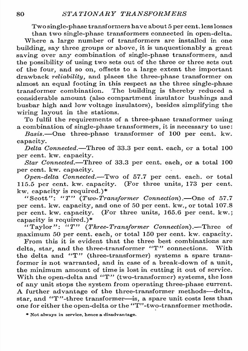
8/11/2019 Transformer Practice 1000194704
http://slidepdf.com/reader/full/transformer-practice-1000194704 92/290
80
STATIONARY
TRANSFORMERS
Two
single-phase
ransformers
have
about 5
per
cent,
less
losses
than
two
single-phase
transformers
connected
in
open-delta,
Where
a
large
number of
transformers
are
installed in
one
building,
say
three
groups
or
above,
it
is
unquestionably
a
great
saving
over
any
combination
of
single-phase
transformers,
and
the
possibility
f
using
two sets out
of
the
three
or
three
sets
out
of
the
four,
and
so
on,
offsets
to
a
large
extent
the
important
drawback
reliability,
nd
places
the
three-phase
transformer
on
almost
an
equal
footing
in
this
respect
as
the
three
single-phase
transformer
combination.
The
building
is
thereby
reduced
a
considerable amount
(also
compartment
insulator
bushings
and
busbar
high
and
low
voltage insulators),
esides
simplifying
he
wiring layout
in
the
stations.
To
fulfil
the
requirements
of
a
three-phase
transformer
using
a
combination
of
single-phase
transformers,
it
is
necessary
to
use:
Basis.
One
three-phase
transformer
of
100
per
cent.
kw.
capacity.
Delta Connected.
Three
of
33.3 per
cent,
each,
or a
total
100
per
cent.
kw.
capacity.
Star
Connected.
Three
of
33.3
per
cent,
each,
or
a
total
100
per
cent.
kw.
capacity.
Open-delta
Connected.
Two
of
57.7
per
cent,
each,
or
total
115.5
per
cent.
kw.
capacity.
(For
three
units,
173
per
cent,
kw.
capacity
is
required.)*
Scott : T
(Two-Transformer
Connection).
One of 57.7
per
cent.
kw.
capacity,
and
one
of
50
per
cent,
kw.,
or
total
107.8
per
cent.
kw.
capacity.
(For
three
units,
165.6
per
cent.
kw.
;
capacity
is
required.)*
Taylor :
T
{Three-Transformer
Connection).
Three
of
maximum
50
per
cent,
each,
or
total
150
per
cent.
kw.
capacity.
From
this
it
is
evident that
the
three
best
combinations
are
delta,
star,
and the
three-transformer
T
connections. With
the
delta
and
T
(three-transformer)systems
a
spare
trans-ormer
is
not
warranted,
and
in
case
of
a
break-down
of
a
unit,
the
minimum
amount
of time
is
lost
in
cutting
it
out
of service.
With
the
open-delta
and
T
(two-transformer)
systems,
the
loss
of
any
unit
stops
the
system
from
operating
three-phase
current.
A
further
advantage
of
the
three-transformer
methods
delta,
star,
and
T
-three
transformer
is,
a
spare
unit
costs
less
than
one
for
either
the
open-delta
or
the
T -two-transformer
methods.
*
Not
always
in
service,
hence
a
disadvantage.

8/11/2019 Transformer Practice 1000194704
http://slidepdf.com/reader/full/transformer-practice-1000194704 93/290
THREE-PHASE
TRANSFORMATION
SYSTEM
81
CONNECTIONS
FOR
GROUNDING
THREE-PHASE
SYSTEMS
In
Fig.
74
several methods
are
shown
for
grounding
three-
phase
systems.
For
(A)
and
(B)
there
is
a
choice
between
the
ground shown,
or
the
ground
at x.
For
(A)
the
ground
as
shown
Fig.
74.
Method
of
grounding
three-phase
systems.
represents
a
maximum difference
of
potential
between
ground
and
line
terminal
of
t~
E,
and
y^
E
for
the
ground
at
x.
For
{B),
the
maximum
voltage
stress
from
line terminal
to
ground
is
full-line
voltage,
but
with
a
ground
made
at
x
the
6
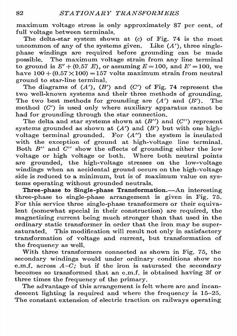
8/11/2019 Transformer Practice 1000194704
http://slidepdf.com/reader/full/transformer-practice-1000194704 94/290
82
STATIONARY TRANSFORMERS
maximum
voltage
stress
is
only
approximately
87
per
cent,
of
full
voltage
between
terminals.
The delta-star
system
shown
at
(c)
of
Fig.
74 is the
most
uncommon
of
any
of
the
systems
given.
Like
(A'),
three
single-
phase
windings
are
required
before
grounding
can
be made
possible.
The
maximum
voltage
strain
from
any
line terminal
to
ground
is
E'
+
(0.57 E),
or
assuming
E
=
100,
and
E'
=
100,
we
have
100
+
(0.57
X
100)
=
157
volts
maximum strain
from
neutral
ground
to
star-line
terminal.
The
diagrams
of
(A'),
(B')
and
(C)
of
Fig.
74
represent
the
two
well-known
systems
and
their
three methods
of
grounding.
The
two
best methods
for
grounding
are
(A')
and
(B').
The
method
(C)
is
used
only
where
auxiliary
apparatus
cannot
be
had
for
grounding
through
the
star
connection.
The delta and
star
systems
shown
at
(B )
and
(C )
represent
systems grounded
as
shown
at
(A')
and
(B')
but
with
one
high-
voltage
terminal
grounded.
For
(A )
the
system
is insulated
with
the
exception
of
ground
at
high-voltage
line
terminal.
Both
B and C
show
the
effects
of
grounding
either
the
low
voltage
or
high
voltage
or
both.
Where both neutral
points
are
grounded,
the
high-voltage
stresses
on
the
low-voltage
windings
when
an
accidental
ground
occurs on
the
high-voltage
side is
reduced
to
a
minimum,
but
is
of
maximum
value
on
sys-ems
operating
without
grounded
neutrals.
Three-phase
to
Single-phase
Transformation.
An
interesting
three-phase
to
single-phasearrangement
is
given
in
Fig.
75.
For
this service
three
single-phase
ransformers
or
their
equiva-ent
(somewhat
special
in their
construction)
are
required,
the
magnetizing
current
being
much
stronger
than
that used
in
the
ordinary
static
transformer
in
order
that
the
iron
may
be
super-aturated.
This
modification will
result
not
only
in
satisfactory
transformation
of
voltage
and
current,
but
transformation of
the
frequency
as
well.
With
three
transformers
connected
as
shown
in
Fig.
75,
the
secondary
windings
would under
ordinary
conditions
show
no
e.m.f.
across
A-C;
but
if
the
iron
is
saturated the
secondary
becomes
so
transformed that
an
e.m.f.
is obtained
having
3f
or
three
times
the
frequency
of the
primary.
The
advantage
of
this
arrangement
is
felt
where
arc
and
incan-escent
lighting
is
required
and
where
the
frequency
is
15-25.
The
constant
extension
of
electric traction
on
railways
operating

8/11/2019 Transformer Practice 1000194704
http://slidepdf.com/reader/full/transformer-practice-1000194704 95/290

8/11/2019 Transformer Practice 1000194704
http://slidepdf.com/reader/full/transformer-practice-1000194704 96/290
CHAPTER
V
THREE-PHASE
TRANSFORMER
DIFFICULTIES
Most
of the troubles which
occur
on
transmission
systems
are
put
down
to
line
surges, resonance,
or some
unknown
phenom-non
on
lines,
and
as a
matter
of fact
most
of
the troubles
might
be
in
the
transformers
themselves,
which
may
be
damaged
and
their
phase
relations
twisted
so as
to
produce,
in
some
in-tances,
many
times the
normal
voltage.
The
most
disastrous troubles
that
can
happen
to
a
three-phase
system
are
those
of
complex
grounds
and
short-circuits.
Witli
a
grounded
neutral
star
system,
a
ground
on
any
one
phase
is
a
short-circuit
of the
transformers,
and
the
entire
group
becomes
disabled until
changes
are
made.
^
-4000
-4000
4000-
ma)
-4000-
- -4000
QMJ
^^^ ^^Mm\^f^mmxjimm^
-600CO
-60000^
^60000-^
103557
60000
Fig.
76.
One transformer
short-circuited
and
cut out
of
delta.
The
voltage
between
windings
and
the
core
is limited
to
57.7
per
cent,
of that of the
line,
and the
insulation
between
the
windings
and
the
core
is
likewise reduced
in
proportion.
The
voltage
between
mains
and the
ground
is
57.7
per
cent,
of
the
line
voltage,
with
a
star
connection,
but the neutral
point
may
move so
as
to
increase the
voltage
with
an
ungrounded system.
If
one
circuit
is
grounded,
the
voltage
between
the
other
two
circuits and
the
ground
is
increased,
and
may
be
as
great
as
the
84

8/11/2019 Transformer Practice 1000194704
http://slidepdf.com/reader/full/transformer-practice-1000194704 97/290
THREE-PHASE
TRANSFORMER DIFFICULTIES 85
full
line
e.m.f.
Such
unbalancing
would
cause
unequal
heating
of
the
transformers
and
if
a
four-wire
three-phase
system
of
distribution
were
employed,
would
prove
disastrous
to
the
regu-ation
of
the
voltage.
With
a
star-delta
system
as
shown
in
Fig.
76,
where
a
trans-ormer
is
short-circuited
and
cut out
of
delta
on
the
secondary,
it is
possible
o
obtain
V
3
times
the
potential
of
any
one
of
the
transformers.
In
Fig.
7Q A B
C
represents
the
vector
triangle
of
e.m.fs.
on
the
primary
with
full
line
voltage
or
4000
volts,
impressed
on
the
transformers,
which
under
normal
conditions
should be
4000
X
7=
=
2300
volts.
The
phase
relations
are
changed
to
60
degrees,
converting
the
original
star
arrangement
to
an
open
delta;
one
phase
is
Fig.
77.
Primary
e.m.fs. and
phase
relations.
reversed,
the
resultant
e.m.f.being
the
same
as
that
across
any
two
phases.
See
also
vector
diagram.
Fig.
77.
As
each
transformer is
only
designed
for
2300
volts
the
e.m.f.
across
the
secondary
windings
should
be
34,600 volts,
but
in this
case
the
voltages
are
34,600
times
V
3
or
60,000
volts.
The
secondary
vector
e.m.fs.
are
graphically
epresented
to
the
right
of
Fig.
76.
In
order
to
bring
the
resultant
vector
secondary
e.m.f.,
and
c,
in
its
proper
position
the
components
must be
drawn
parallel
with
the
primaries.
One
secondary
winding
is
short-circuited
and
cut out
of
delta
leaving
an
open-delta
connection
reversed
in
direction,
ts
phase
relations
being
changed
from
60 to
120
degrees:
increasing
the
voltage
between
a
and
c
to
34,600X1732X1732=103,557
volts.
or\/3X\/3X34,600=
103,577
volts.

8/11/2019 Transformer Practice 1000194704
http://slidepdf.com/reader/full/transformer-practice-1000194704 98/290
86
STATIONARY
TRANSFORMERS
This is
a
very
important
point
to
bear
in
mind,
especially
when
generators
are
tied
directly
to
the
system
without
fuses
or
any
protecting
devices.
The
voltages
impressed
on
the
primary
windings
of
Fig.
7G
and 77
are:
Aand
B
=
4000
volts,
5 and C
=
4000
volts,
A
and C
=
4000
volts.
E.m.fs.
between the
primary
neutral
and
any
line,
re:
A nd A'
=
4000
volts,
which
should be
6000X0.577
=
2300
volts;
B
and S'
=
0
volts,
which
should be
2300
volts;
C and
C
= 4000
volts,
which
should be
4000X0.577
=
2300 volts.
The e.m.fs. between the
secondary
lines,
re:
a
and
6
=
60,000
volts,
which
should be
60,000X0.577
=
34,600
volts;
andc
=
103,577
volts,
which
should
be
103,577^2.99
=
34,600
volts;
a
and
c
=
60,000 volts,
which
should
be
60,000X0.577
=
34,600
volts.
The increases
in
e.m.f.
across
the
secondary
lines,
re:
a
and
c
=
173
per
cent,
above
normal,
b and
c
=
300 per
cent,
above
normal,
a
and
=
173
per
cent,
above
normal.
It
is
also
found that where the
neutral
points
of
the
primary
and
secondary windings
are
grounded,
the
opening
of
one
or
two
of
the three
line circuits will
cause
currents
to
flow
through
the
ground.
A
partial
ground
on
a
line
circuit
will
partially
short-
circuit
one
transformer
and
cause
current
to
flow
through
the
ground
and
the neutral.
The actual
strain
between
high-tension
nd
low-tension wind-ngs
is
equal
to
the
high-tension
voltage
plus
or
minus
the low-
tension
voltage,depending
upon
the
arrangement
and
connection
of
the
coils;
ut
as
the
low-tension
voltage
is
usually
a
small
per-entage
of
that
of the
high-tension,
it is
customary
to
assume
that the
strain
between
windings
is
equal
to
that
of
the
high-
tension
voltage
alone.
If
the neutral
points
of the
high-tension
and
low-tension
windings
are
grounded,
the
iron
core
being
also
grounded,
then

8/11/2019 Transformer Practice 1000194704
http://slidepdf.com/reader/full/transformer-practice-1000194704 99/290
t
THREE-PHASE
TRANSFORMER
DIFFICULTIES 87
as
long
as
the
circuits
are
balanced the
voltage
strains will
be
the
same
as
with
the
windings
ungrounded,
and
balanced;
but
in
case
of
a
ground
on
either
high-tension
or
low-tension
line,
r
in
case
of
a
connection
between
high-tension
and
low-tension wind-ngs,
a
portion
of
the
windings
will
be
short-circuited.
Assuming
that all
lines
and
transformers
are
in
good shape,
that
is
to
say,
clear
from
grounds
and
short-circuits,
t is
possible
to
obtain
any
of
the
following
results shown
in
Figs.
78,
79,
80 and
81,by
connecting
the
receiving
ends of
transmission
lines
to
a
wrong
phase
terminal
receiving
hree-phase
current
from another
source
of
supply,
or
by
switching
together
groups
of
two
or
more
transformers of
the
wrong
phase
relations.
Fig.
78.
Re.sultant
e.m.fs.,
and
phase
relations
of
improper
delta-delta
and
star-star
connected
group
of
transformers.
Fig.
78
represents
the result
of
a
delta-delta
and
star-star
combination
thrown
together
at 120
degrees
apart,
both
trans-ission
lines
receiving
three-phase
currents
of
the
same
potential,
phase
relations,
nd
frequency.
The
resultant
voltage
obtained in
attempting
to
parallel
two
groups
of
three
transformers
star
connected
is
\/^
times
the
e.m.f.
between
any
two
line
wires,
r
Star
=
(57.7
X
1.732
=
100)
X
(1.732)
173.2 volts.
The
combination
shown in
Fig.
79
represents
four
groups
(three
single-phase
ransformers
in
each
group)
connected
to
one
set
of
busbars. Each
group
receives
three-phase
current
from
independent
source
of
supply
and
is
so
tied in
on
the
primary
and
secondary
busbars
as
to
involve
a
partial
short-circuit.
In
common
practice
this
combination is
more
often
likely
to
happen
on
large
distributing
systems
where all transformers
in

8/11/2019 Transformer Practice 1000194704
http://slidepdf.com/reader/full/transformer-practice-1000194704 100/290
88
STATIONARY
TRANSFORMERS
groups
are
tied
together
on
primaries
and
secondaries. As
wih
be
noticed,
any
attempt
to
connect
such
a
system
with
all
pri-ary
windings
and all
secondary
windings
of each
group
in
parallel
will
produce
a
short-circuit.
Fig.
79.
Representation
of
a
complete
combination of
delta-delta
and
delta-star
transformer
group
connections.
Figs.
80
A
and B.
Graphic
illustration
of
e.m.fs.
and
phase displacement
of
two delta-delta
to
delta-star
connected
groups
of transformers.
With
a
delta-star
presupposed parallel
operation
it is
impos-ible
to
change
the
magnetic
field
to
correct
the
phase
displacement

8/11/2019 Transformer Practice 1000194704
http://slidepdf.com/reader/full/transformer-practice-1000194704 101/290
THREE-PHASE
TRANSFORMER DIFFICULTIES 89
which
occurs,
though
it
is
possible
n
the
case
of
generators
which
are
necessary
for
permitting
the
30
degrees
electrical
displace-ent
to
be
corrected
by
a
mechanical
twisting
of
the
phases
with
respect
to
their
magnetic
fields;
but with transformers
it is
impossible.
The
phase
displacements
show
a
star
connection introduced
in
which the
relative
e.m.f.
positions
re
changed by
an
angle
30
degrees. If,
for
example,
we assume
the
line
potential
to
be
60,000
volts,
and
we
attempt
to
connect
the
groups
as
shown
in
diagram,
the result
will
be
voltages
as
high
as
116,000.
Fig.
81.
E.m.fs.
and
phase
relation
of
a
delta-delta
to
delta-star
connected
group
of
transformers.
The
resultant
e.m.fs. established
by
this
experiment,
are
shown
separately
in
Figs.
80 and
81.
They
are
correctly:
B
to
B
=
84,840
volts,
which
should be
=
0
B''
to
C
=116,000
volts,
which
should
be
=60,000
A
to
C
=116,000
volts,
which
should
be
=60,000
A''
to
B
=116,000
volts,
which
should
be
=60,000
A'
toB
=
84,840
volts,
which
should
be
=60,000
A'
to
C
=
31,000
volts,
which
should
be
=60,000
C
to
B
=116,000
volts,
which should be
=60,000
C
to
B
=116,000
volts,
which
should
be
=60,000
C
to
C
=
84,840
volts,
which
should be
=60,000
B'
to
B
=
31,000
volts,
which
should be
=
0
B '
to
^
=
31,000
volts,
which
should
be
=60,000
A'
to
A
=
31,000 volts,
which
should be
=
0
A '
to
B
=
84,840
volts,
which
should
be
=60,000
A fact
not
very
well
recognized,
s
the
impossibility
f
parallel-ng
certain
primary
and
secondary three-phase
systems.
The
following
combinations
can
be
operated
in
parallel:

8/11/2019 Transformer Practice 1000194704
http://slidepdf.com/reader/full/transformer-practice-1000194704 102/290
90
ST
A
TIONARY
TRANSFORMERS
Delta-star
group
with
a
delta-star.
Star-star
group
with
a
star-star.
Delta-delta
group
with
a
delta-delta.
Star-delta
group
with
a
star-delta.
Delta-star
group
with
a
star-delta.
Star-star
group
with
a
delta-delta.
Fig. 82.
^Practical
representation
of
a
delta-delta
to delta-star connected
group
of
transformers.
These
delta-star
combinations
necessitate
changing
trans-ormer
ratios
of
primary
and
secondary
turns,
as:
Delta-star is
a
constant
of VS =1.733
to 1.
Star-delta
is
a
constant
of
;=
=0.577
to
1.
\/3
consequently,
special
ratios
of
secondary
to
primary
turns
are
needed
in
delta-star
or
star-delta
transformers,
in
order
to
pro-uce
standard
transformation ratios.
As
already explained,displacement,
of
phase
relations
occur
on
the
secondary
side
of transformers
when
two
or more
groups
are
connected
delta-delta and
a delta-star;
the
delta-delta
having
a
straight
ratio
and the
delta-star
a
ratio
of
1
to
0.577;
or
any
of the
following
combinations:
Delta-star ratio
= to
1^
and
star-star
with
ratio
1
to
1,
or
\/3
any
ratio.
.
1
Delta-delta,
ratio
1
to
1,
with
a
star-star
ratio
~;Eto
1,
or
any
vo
ratio.

8/11/2019 Transformer Practice 1000194704
http://slidepdf.com/reader/full/transformer-practice-1000194704 103/290

8/11/2019 Transformer Practice 1000194704
http://slidepdf.com/reader/full/transformer-practice-1000194704 104/290
92
STATIONARY
TRANSFORMERS
in
each
unit
will
be
in
phase
with
the
current
in
the
line,
also
the
sum
of the
currents
will
be the
same
as
the
line
current.
With
unequal
ratios
of
resistance
to
reactance
the
current
in
each
unit
will
not
be
in
phase
with
the
current
in
the
line,
therefore
the
sum
of
the
currents
will
be
greater
than
the
line
current.
If,
however,
the
impedance
of
the
units
is
the
same,
both
will
carry
the
same
per
cent,
of
full-load
current;
and
if,
in
addition,
the
ratio
of
resistance
to reactance
is
the
same
in both
cases,
the
current
in
the
two
units will be
in
phase
with each
other,
and
their numerical
sum
will
equal
the load
current,
thus
there will
exist
perfect
parallel
operation.
^AAAAJ
\
Vv ^AA_,_/y/VAA'V^
l^'V^V.
^ N^^ j^S.^^
f^
^ ^^
\oc\
\a a\
b
c\
a 6
Fig.
83.
Whatever
scheme
of transformers
is
decided
on
for
a given
system
it
will
always
be
advisable
to
keep
to
that
scheme
if
possible;
this is
particularlyapplicable
on
some
of the
larger
systems
of
100
megawatts
and
over
where
networks
of
high-
voltage
transmission
lines
and
sub-stations
are
numerous.
Quite
a
number
of
systems
have
distance
sub-stations
with
only
two
groups
of
transformers,
both
groups
being
operated
in
parallel
at
all
times.
Assuming
the transformers
to
be
con-ected
in
delta-delta
and
one
transformer of
one
of the
groups
becomes
damaged,
it
might
mean,
if
the
load is
great,
that
at
least
one
of
the other
group
must
be
cut out.
If the
load
is
not
greater
than 80
per
cent,
of
their
total
rating
it will
be
possible
under
ordinary
circumstances
to
operate
the
closed
delta
group
with the
open-delta
as
shown
in
Fig.
83.
It
is
not
generally
known that there
are
sixteen
different
con-ections
on one
transformer
star-connected
group,
and that these
connections
can
be
changed
about
to
obtain
several
parallel
combinations,
such
as
those shown
in
Fig.
84
giving
the
time-
phase
of
0,
30, 60,
and
90
degrees
(electrical).

8/11/2019 Transformer Practice 1000194704
http://slidepdf.com/reader/full/transformer-practice-1000194704 105/290
THREE-PHASE
TRANSFORMER DIFFICULTIES
93
Primary
Conaection
of
Transformers
With
Secondary
Connection
of
Transformers
In
Phase
^^
60
degrees
out of
phase
bt--
^
Y
X
30
degrees
out
of
phase
A
90
degrees
out of
phase
Fig. 84.
A

8/11/2019 Transformer Practice 1000194704
http://slidepdf.com/reader/full/transformer-practice-1000194704 106/290
94
ST
A
TIONA
R
Y
TRA
NSFORMERS
Not
including
the
straight
star
or
delta
connection
with
a
time-phase
angle
equal
to
zero,
we
find
that
there
are
no
less
than
three
different
groups
such
that
transformers
belonging
to
the
same
group
can
be
connected
in
parallel,
while
if
of
different
groups,
no
parallel
connection
is
possible
without
a
special
rearrangement
of
the
internal
connections
of
the
transformers.
Fig.
85.
High-voltage
line
grounded,
producing
maximum
strain
on
low
voltage windings.
(Neutrals
non-grounded.)
The
troubles
usually
experienced
with
high-voltage
trans-ormers
can
be classified
as:
(a)
Puncturing
of
the insulation
between
adjacent
turns
due
to
surges,
etc.
(6)
Shifting
of
coils
duo
to
switching
on
and
off
very
heavy
loads.
(c)
Terminals
puncture
(transformer
insulator
bushing
and
other
leads),
due
to
either
(a)
or
(b)
or
both.
There
are
a large
number
of
causes
for
transformer
break-owns,
some
of
them
being
:
(1)
Insufficient
insulation
between
layers
and
turns.

8/11/2019 Transformer Practice 1000194704
http://slidepdf.com/reader/full/transformer-practice-1000194704 107/290
THREE-PHASE
TRANSFORMER
DIFFICULTIES
95
(2)
Insufficient
insulation
on
the end-turns.
(3)
Electromagnetic
stresses
too
great.
(4)
Electrostatic
capacity
of
certain
parts
too
high.
(5)
Condenser
effect
between
coils,
nd
between
windings
and
ground
too
high.
(6)
Improper
drying
out
after
construction.
(7)
For
want
of
a
choke
coil
or
reactance
in
series.
(8)
Concentrated
condensers
in
parallel
with
transformer
windings.
-E-
B
W-E-^E-
^vA^N^
Un^'V^V/^
t'-N/S^.^
rrv^:^^^:^
El
-Ey
^^e-
E^A^JJ,
\
1
Fig.
86.
Showing
the effect
of
grounding
the
low-voltage
neutral.
(9)
Two
or
more
of the above
in
connection with
concentrated
condensers.
(10)
Internal short-circuits.
(11)
Conditions of
switching,
urges,
arcing
grounds,
lightning,
etc.
(12)
Improper
treatment
of the
oil.
(13)
Oil
not
suited
to
the
transformer.
(14)
Thickening
of
oil
and
clogging
of
cooling
medium
stopped.
(15)
Leaking
water-coils,
or,
circulation of
cooling
medium
stopped.
(16)
Breathing
action
(prevalent
n
damp
localities).

8/11/2019 Transformer Practice 1000194704
http://slidepdf.com/reader/full/transformer-practice-1000194704 108/290
96
STATIONARY
TRANSFORMERS
(17)
Improperly
installed
protective
apparatus.
(18)
High
winds which
bring
live
conductors
in
oscillation.
(19)
Defective
governors
or
prime-movers.
(20)
Variation in
speed
of
generators.
(21)
Variation in
generator
voltage.
(22)
Roasting
by
constant
over-load.
(23)
Puncturing
of
transformer
terminals.
(24)
When
transformers
are
connected
to
generating
stations
and
systems
and bus-bars
having
a
total
kw.
capacity
many
times
greater.
Figs.
85, 86,
and
87
show
other
causes
for break-downs
in
high-
voltage
transformers.
Three
different
conditions
of
operation
are
given;
one
for
an
insulated
delta-delta
system
showing
the
effects
of
a
grounded
live
conductor,
one
for
a
delta-delta
system
with the
neutral
point
of
low-voltage
windings
grounded,
and the
other for
a
delta-delta
system
with
both
high-
and
low-voltage
windings grounded.
The
approximate
maximum
potential
strains
are
shown
by
the
vector
relations.
These
serve
to
show
other
greater
difficulties which
receiving-station
transformers
are
subjected
to
in
addition
to
those
usually
impressed
on
the
transformers
at
the
generating
stations.

8/11/2019 Transformer Practice 1000194704
http://slidepdf.com/reader/full/transformer-practice-1000194704 109/290
CHAPTER
VI
THREE-PHASE
TWO-PHASE
SYSTEMS
AND
TRANSFORMATION
With
two
or
three
single-phase
transformers
it is
possible
to
have
three-phase primaries
with
two-phase
secondaries,
or
vice
versa.
For
long-distance
transmission
of
electric
power
the
three-phase
system
is
universally
adopted
because
it
requires
less
copper
for
the
line
than
either the
single-phase
or
the
two-
M
Uy^(\ri
l/N/vvJ
U./ ^saI
i^'iddc
kiac
't
-Ey-
-r
Fig.
87.
This
shows the
effect
of
grounding
both
the
high-
and low-
voltage
neutrals, resulting
in minimum
voltage
strain.
phase
systems
to
transmit
a
given
amount
of
power
with
a given
line
loss,
and with
a
given
line
voltage.
The
two-phase
system
offers
certain
advantages
over
the
three-phase
system
when
applied
to
local distribution
of electric
power.
In
Fig.
88
is
shown
the well
known
three-phase
three-wire
to
7
97
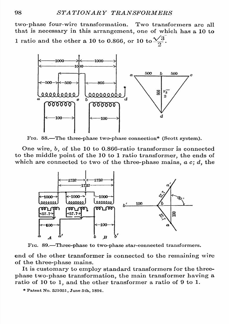
8/11/2019 Transformer Practice 1000194704
http://slidepdf.com/reader/full/transformer-practice-1000194704 110/290
98
ST A
TIONARY
TRANSFORMERS
two-phase
four-wire
transformation.
Two
transformers
are
all
that is
necessary
in
this
arrangement,
one
of
which
has
a
10 to
1
ratio
and
the
other
a
10
to
0.866.
or
10
to^.
Fig.
88.
The
three-phase
two-phase
connection*
(Scott system).
One
wire,
6,
of the
10
to
0.866-ratio
transformer is
connected
to
the
middle
point
of the
10
to
1
ratio
transformer,
the ends
of
which
are
connected
to
two
of the
three-phase
mains,
a
c;
d,
the
wooo
-1732
^1732
-1733
-iooo-^
-1000
4 ^'H
W[JW
100-
-100-
Fig.
89.
Three-phase
to
two-phase
star-connected transformers.
end
of
the
other transformer
is connected
to
the
remaining
wire
of
the
three-phase
mains.
It
is
customary
to
employ
standard
transformers
for the
three-
phase
two-phase transformation,
he
main
transformer
having
a
ratio
of
10
to
1,
and the other transformer
a
ratio
of
9 to 1.
*
Patent
No.
521051,
June
5th,
1894.

8/11/2019 Transformer Practice 1000194704
http://slidepdf.com/reader/full/transformer-practice-1000194704 111/290
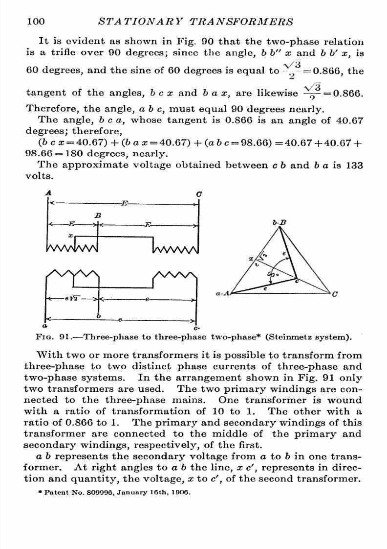
8/11/2019 Transformer Practice 1000194704
http://slidepdf.com/reader/full/transformer-practice-1000194704 112/290
100
STATIONARY
TRANSFORMERS
It
is
evident
as
shown
in
Fig.
90
that the
two-phase
relation
is
a
trifle
over
90
degrees;
since
the
angle,
6 b
x
and
b
b'
x,
is
60
degrees,
and the
sine of
60
degrees
is
equal
to
V3
0.866.
the
V3
tangent
of
the
angles,
b
c x
and
b
ax,
are
likewise
-^^=0.866.
Therefore,
the
angle,
ab
c,
must
equal
90
degrees
nearly.
The
angle,
b
c
a,
whose
tangent
is
0.866
is
an
angle
of
40.67
degrees;
therefore,
(6
ca;
=
40.67)
+
(
a a;
=
40.67)+
(a
6
c
=
98.66)
=40.67
+
40.67
+
98.66
=
180
degrees,
nearly.
The
approximate voltage
obtained
between
c
6
and
fe
a
is
133
volts.
Fig. 91.
Three-phase
to
three-phasetwo-phase*
(Steimnetz
system).
With
two
or more
transformers
it is
possible
to
transform
from
three-phase
to two
distinct
phase
currents
of
three-phase
and
two-phase
systems.
In
the
arrangement
shown
in
Fig.
91
only
two
transformers
are
used.
The
two
primary windings
are con-ected
to
the
three-phase
mains.
One
transformer
is
wound
with
a
ratio
of
transformation
of
10
to
1.
The
other
with
a
ratio
of
0.866
to
1.
The
primary
and
secondary
windings
of
this
transformer
are
connected
to
the
middle
of the
primary
and
secondary
windings,
respectively,
f the first.
a
b
represents
the
secondary
voltage
from
a
to
6
in
one
trans-ormer.
At
right
angles
to
a
6
the
line,
x
c',
represents
in
direc-ion
and
quantity,
the
voltage,
x
to
c',
of
the
second
transformer.
*
Patent No.
809996,
January
16th,
1906.

8/11/2019 Transformer Practice 1000194704
http://slidepdf.com/reader/full/transformer-practice-1000194704 113/290
THREE-PHASE
TWO-PHASE
SYSTEMS 101
At
the
terminals,
ab
c,
three
equal
voltages
will
exist,
each
differing
rom
the
other
by
60
degrees,
and
giving
rise
to
a
three-
phase
current.
-1000-
-1000
U51AMM5J
-1000-
UftMiKMiU
\'
n
u
z
hco
J
-100-
-ico
X
-ico-
FiG.
92.
Three-phase
T
to
two-phase
four-wire.
It
also
follows
that,
at
the
terminals
a
b
and
x
c',
two
equal
voltages
will
exist,
ach
differing
rom
the
other
by
90
degrees,
and
giving
rise
to
a
two-phase
current.
As
will
be
noted,
the
-1000-
-1000-
-1000-
npsm
m\
-8676-
-100-
-100-
-100-
B'
Fig.
93.
Three-phase
open
delta
to
three-phasetwo-phase
(Taylor
system).
voltages
obtained
in
the
three-phase
side
are
equal
to
those
between
any
phase
of
the
two-phase
system.
The
arrangement
in
general
is
similar
to
that of the
ordinary
V
or
open-delta
system.
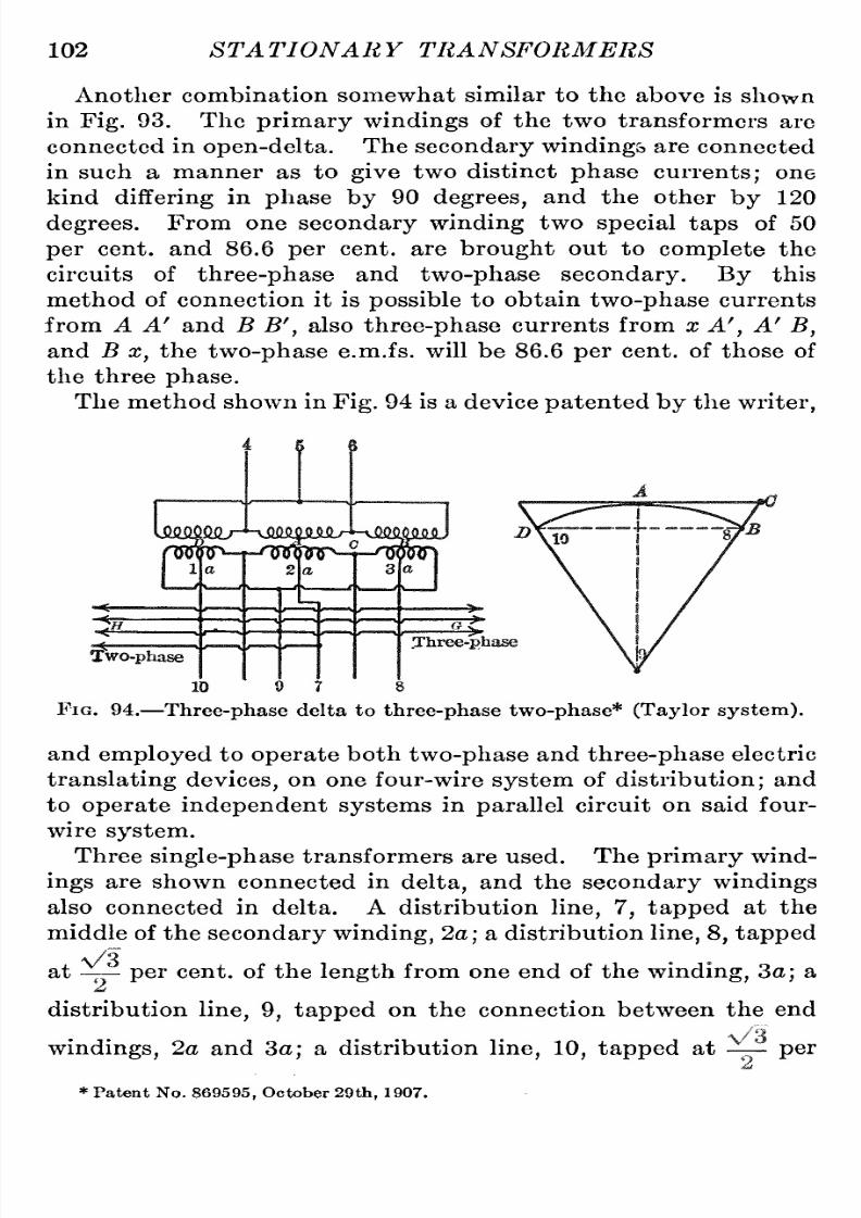
8/11/2019 Transformer Practice 1000194704
http://slidepdf.com/reader/full/transformer-practice-1000194704 114/290
102
STATIONARY TRANSFORMERS
Another
combination
somewhat similar
to
the
above is
shown
in
Fig.
93. The
primary windings
of
the
two
transformers
are
connected
in
open-delta.
The
secondary
windings
are
connected
in
such
a
manner as
to
give
two
distinct
phase
currents;
one
kind
differing
in
phase
by
90
degrees,
and
the
other
by
120
degrees.
From
one
secondary
winding
two
special
taps
of
50
per
cent,
and
86.6
per
cent,
are
brought
out to
complete
the
circuits
of
three-phase
and
two-phase
secondary.
By
this
method
of
connection it is
possible
to
obtain
two-phase
currents
from A A' and B
B'
,
also
three-phase
currents
from
x
A'
,
A'
B,
and B x, the
two-phase
e.m.fs.
will be
86.6 per
cent,
of
those
of
the three
phase.
The method
shown
in
Fig.
94
is
a
device
patented by
the
writer,
Fig.
94.
Three-phase
delta
to
three-phase
two-phase*
(Taylor
system).
and
employed
to
operate
both
two-phase
and
three-phase
electric
translatingdevices,on one
four-
wire
system
of
distribution;
and
to
operate
independent
systems
in
parallel
circuit
on
said
four-
wire
system.
Three
single-phase
ransformers
are
used.
The
primary
wind-ngs
are
shown connected
in
delta,
and the
secondary
windings
also
connected
in
delta.
A
distribution
line,
7,
tapped
at
the
middle
of
the
secondary
winding,
2a;
a
distribution
line,
8,
tapped
\/3
.
at
- -
per
cent,
of
the
length
from
one
end of
the
wmdmg,
3a;
a
distribution
line,9,
tapped
on
the
connection
between
the
end
windings,
2a and
3a;
a
distribution
line,10,
tapped
at
-
per
*
Patent No.
869595,
October
29th,
1907.

8/11/2019 Transformer Practice 1000194704
http://slidepdf.com/reader/full/transformer-practice-1000194704 115/290
THREE-PHASE
TWO-PHASE SYSTEMS
103
cent,
of
the
length
from
the
end
of
windhig
la,
and
translating
means
connected
on
said
distribution
lines
both
for
two-
and
three-phase
on.
At
la,
2a
and
3a
are
the
secondary
windings
of
said
trans-ormers.
The
secondary
winding,
la,
is
tapped
at
D,
which is
about 86.6
per
cent,
of
its
length,by
the
line,10;
which
serves
also
as a
leg
for
both the
two-
and
three-phase
circuits.
The
secondary
winding,
2a,
is
tapped
at
its
central
point
A,
by
a
line,
;
forming
one
leg
of
the
two-phase
circuit.
The
secondary
winding, 3a,
is
tapped
at
approximately
86.6
per
cent,
of
its
length
from
one
end,
at
about
the
point,
B, by
a
line,
8,
to
serve
s
\
1
,
I
i
^
ft^
Fig.
95.
Three-phase
to
two-phase, giving
86
per
cent,
standard
trans-ormer
taps.
as
one
leg
of
both the three-
and
two-phase
circuits.
C
represents
the
point
of
a
tap
taken from
the
junction
of
two
secondary
windings
which
are
shown
connected
in
the
series
circuit,
which
serves as
another
leg
for
both
two-
and
three-phase
circuits.
The
arrangement
accomplishes
the
operating
of
non-synchro-ous
apparatus
of
two-phase
and
three-phase
design
without
the
aid
of transformers
or
split-phase
devices.
The
operation
consists
in
generating
three-phase
alternating
currents
in
the

8/11/2019 Transformer Practice 1000194704
http://slidepdf.com/reader/full/transformer-practice-1000194704 116/290
104
^TA TIONA
R Y
TRA
NSFORMERS
lines,
4,
5
and
6,
transforming
the
same
into
three-phase
cur-ents
in
the
legs,
8,
9
and
10,
and
into
two-phase
currents
in
the
legs,
7, 8,
9
and
10;
and
in
operating
translating
devices
EV3-
E
E
^^A/wJ
IAAW\
AAA
c^
e'
Fig.
96.
at
G and H
in
parallel
with
the
two-
and
three-phase
current
circuits.
The
two-phase
windings
used
on
the
motors must
be
sA/yw/s
-1000-
J9
0
1000
-1000-
-1000-
WSAAA
-1000
d
Fig.
97.
independent
as
the
interconnected
type
of
winding
would
not
operate
on
this
system,
A
three-phase
single-phase
transformation
is
shown
in
Fig.
98.

8/11/2019 Transformer Practice 1000194704
http://slidepdf.com/reader/full/transformer-practice-1000194704 117/290
THREE-PHASE
TWO-PHASE SYSTEMS
105
The
objection
to
this connection
is
the
distorted
effect
of the
relative
voltages
and
phase
relations
of
the
three-phase
when
a
single-phase
load
is
put
on one
of
the
phases.
To obviate
this
to
some
extent
it
would
be
necessary
to
give
the
three-phase voltage
a
slight
distortion.
The
unbalanced
voltages
and
phase
relation
when
a
single-phase
oad
is
applied
is
shown
by
the
vector
in
Fig.
98,
it
having
the effect of
twisting
the
phase
relation
when
a
load
is
applied
between
b-c
from
a
symmetrical point
as
shown
at
the
point
a'.
-1000-
-1000
-
1000
^
Vv/VwJ
\AA/v/W
/S^V^ /S^ s.^
-100-
-100-
a
-100-
FiG.
98.
Three-phase
to
single-pha.se.
-1000-
-^50oH*-eoo-*
-1000-
-1000-
iMKMmJ
100-
fToooD
nmm
-100-
-141-
FiG.
99.
Another
three-phasesingle-phasesecondary
operation.
It is
possible
to
take
currents
from
a
three-phase system
and
transform
them
into
a
single-phase
current
(see
Fig.
99).
All that is
necessary
is
to
arrange
two
transformers
so
that
their
connections
are
identical with the
ordinary
two-phase
to
three-phase
transformation,
the
only
difference
being
in the

8/11/2019 Transformer Practice 1000194704
http://slidepdf.com/reader/full/transformer-practice-1000194704 118/290
106
STATIONARY TRANSFORMERS
secondary,
which has the
two
windings
connected
in
series
for
supplying
a
single-phase
ircuit.
In
the
ordinary
three-phase
to
two-phase
transformation,
the
two
components
in
each
half
of
the
winding
differ
in
phase by
90
Taylor*
Scott
Meyer'
Steinmetz
'
v:
T7
/
Fig.
100.
Two-phase
transformer
windings.
Transformer
windings.
Resultant
two-phase
voltages.
Resultant
three-phase
voltages.
degrees.
However,
when
the
secondary
circuits
are
connected
in
series,
hese
two
component
currents
are
of
one
phase.
The
maj
ority
of
three-phasetwo-phase
transformer
connections
employed
are
for
temporary
or
special
urposes.
This is
particu-
FiG.
101.
Combination of
systems
given
in
Fig.
100.
larly
so
when
only
two
transformers
are
used.
The
systems
used
in
Europe
and
America
are
shown
in
Fig.
100,
in
the
form
of
vectors.
In
comparing
these
various
systems by
means
of
the
Vectors
given,
it is
very
interesting
o note
how
near
they
are
to

8/11/2019 Transformer Practice 1000194704
http://slidepdf.com/reader/full/transformer-practice-1000194704 119/290

8/11/2019 Transformer Practice 1000194704
http://slidepdf.com/reader/full/transformer-practice-1000194704 120/290
108 STATIONARY
TRANSFORMERS
single-phase
transformers
with
winding
cut
into
two
equal
parts
and connected
as
shown.
(/)
is
a
star
connection
with
one
trans-ormer
winding
reversed,
(g)
is
an
ordinary
open-delta
connec-ion.
With
the
exception
of
(a)
and
(g)
which
consist
of
two
single-phase
transformers,
all
the
others
are
three-phase
two-
phase
combinations
using
three
single-phase transformers.
By
the
use
of
transformers
other
than
standard
ratios
and
design,
the
three-phase
two-phase
transformer
combinations
shown
in
Fig.
104
can
be
made.

8/11/2019 Transformer Practice 1000194704
http://slidepdf.com/reader/full/transformer-practice-1000194704 121/290
CHAPTER
VII
SIX-PHASE TRANSFORMATION
AND
OPERATION
In
transforming
from
three-phase
to
six-phase
there
are
four
different
ways of
connecting
the
secondaries
of the transformers:
namely,
diametrical
^with
or
without
the
fixed neutral
point;
double
star;
double
delta;
and
double
tee.
In the
first
three
cases
the
primaries
may
be connected
either
star
or
delta,
according
to
the
voltage
that
each
winding
will
stand,
or
to
obtain
a
required
Fig. 104.
Three-phase
to
two-phase using
special
transformer
tops.
secondary
voltage.
In the last
case,
the
primary windings are
connected
in
tee.
For
the
diametrical
connection
three
single-phase
transformers
may
be
used
with
one
central
tap
from
each
transformer
second-ry
winding,
or
there
may
be
six
secondary
coils. For the
double-star
or
double-delta
connection
two
independent
second-ry
coils
are
required
for
each
transformer;
the second set
are
all
109

8/11/2019 Transformer Practice 1000194704
http://slidepdf.com/reader/full/transformer-practice-1000194704 122/290
110
STATIONARY
TRANSFORMERS
reversed,
then
connected
in
a
similar
manner
to
the first
set.
Hence,
the
phase
displacement
is
shifted
180
degrees.
For
the double-tee
connection
two
single-phase
transformers
are
required,
ne
of
which
has
a
10
to
1
ratio
and the other
a
10
to
0.866,
or
10
to
^
ratio.
There
are
two
secondary
coils
giving
10
to
1
ratios,
nd
two
giving
10
to
0.866
ratios.
In
six-phase
circuits
there
are
coils
with
phase
displacements
of 60
degrees;
each
coil
must
move
through
180
electrical
degrees
from
the
position
here
the
current
begins
in
one
direction,
efore
Fig.
105.
Six-phase
diametrical
e.m.fs.
and
phase
relation.
the
current
begins
to
reverse.
Hence,
for the
double
star,
diametrical,
ouble
delta and
double-tee
connections
if
the ends
of the transformer
coils
are
reversed,
the
phase
displacement
of
the e.m.f.
is
in effect
shifted
180
electrical
degrees.
Take,
for
instance,
the
e.m.fs., a',
hh' and
c
c'
,
as
graphically
explained
in
Figs.
106
and
107,
for
a
diametrical
connection
they
are
equal
io
2
a
x,
2
h
x,
2
c
x,
etc.
For
double-star
connection:
a
,
h'
c,
c
a,
etc.,
is
V
3
times
x
a,
x
h'
,
x
c,
etc.
For
double-delta
connection:
xa,
x
b',
X
c,
etc.,
is
7-
=0.577
per
cent,
of
a
h'
,
h
c,
c
a,
etc.
For
double-tee
connection:

8/11/2019 Transformer Practice 1000194704
http://slidepdf.com/reader/full/transformer-practice-1000194704 123/290
SIX-PHASE
TRANSFORMATION
AND OPERATION
111
a
b',
c,
c
a,
etc.,
is
13.3
per
cent,
more
than
a'
y,
or
a
z.
The
general
statement
of
relationship
etween
e.m.fs.
in
Fig.
106
may
demonstrate
that
if
the
value
of
a
a',
etc.,
is
represented
by
the diameter
of
a
circle,
he
values
of a'
h,
etc.,
are
repre-
Fig.
106.
Six-phase
e.m.fs.
graphically
represented.
sented
by
a
120-degree
chord,
and the
values
of
a
6,
etc.,
are
represented
by
a
60-degree
chord
of
the
same
circle.
If
the
voltage between,
a
6,
etc.,
is
not
required,
only
three
secondary
coils
are
needed;
but ifthis
voltage
should be
required,
|
1000 ^
=
1000
looo
^
100
-60-
nnnjTi
-100-
-50-
(VS^
-100-
-50 ^
Fig.
107.
Six-phase
diametrical connection.
then
six
secondary
coils
are
needed,
or
three
coils
with
a
center
tap
like
that shown
in
Fig.
107.
The
diametrical
connection
of
transformer
secondaries
as
represented
in
Fig.
107
is
the
most
commonly
used of
any
three-phase
to
six-phase
transformations.
One
secondary
coil
on
each
step-down
transformer
is
all
that
is

8/11/2019 Transformer Practice 1000194704
http://slidepdf.com/reader/full/transformer-practice-1000194704 124/290
112
STATIONARY
TRANSFORMERS
necessary;
whereas
the
double-star,double-delta,
and
double-tee
connections
require
two
secondary
coils,
and
therefore
four
secondary
wires
for each
transformer.
The
two
secondary
wires
from each
transformer
are
connected
to
the
armature
winding
of
a
rotary
converter at
points
180
degrees
apart
such
as
shown
at
a
a'
,
b h'
,
c
c'
;
therefore,
arrangements
for
the
diametrical
connection
are
much
simpler
than
any
of the
others.
A
part
of the
three-coil
secondary
diametrical
connection
may
be used
for induction-motor
service
to
start
the
rotary
converter.
-1000-
-1000-
-1000
Fig.
108.
Six-phase
diametrical
connection
with
five-point
switch
used in
connection
with
motor
for
startingsynchronous
converters.
and when
sufficient
speed
is obtained
the
motor may
be
cut out
of
service.
The
arrangement
is
shown
in
Fig.
108.
By
means
of
this
connection,
which is
made
through
the introduction
of
a
five-pole
switch,
a
three-phase
e.m.f.
may
be
obtained,
giving
a
value
equal
to
half
the e.m.f. of each
secondary
winding
times
V
3.
That
is
to
say,
if
half
the e.m.f. of each
secondary
winding
is
equal
to
50
volts,
then
assuming
the
switch
to
be
closed,
we
obtain
50X\/3=86.6
volts.
Similar
ends of the
three
windings
are
connected
to
three
points
on one
side of the
five-pole
witch.
The three
wires
on
the
other

8/11/2019 Transformer Practice 1000194704
http://slidepdf.com/reader/full/transformer-practice-1000194704 125/290
SIX-PHASE TRANSFORMATION
AND OPERATION
113
side of
the
switch
are
led
off
to
the
three-phase
motor
service.
The
two
remaining points
of
the
switch
receive
three
wires from the
neutral
points
of
the
three
secondary windings.
Connections
are
so
made
that
when
the
switch
is
closed
a
star-connection is
obtained.
With
the
double-star
arrangement
of
secondary
windings,
shown in
Fig.
109,
a
rotary
converter
may
be
connected
to
a
given
three
of the
six
secondary coils,
r
one
rotary
may
be connected
to
the
six
secondary
coils.
The
disadvantage
of
star
connection
is
that
in
case
one
transformer is
burned
out,
it
is
not
possible
o
continue
running.
1000
-*p--
1000
-^
^1000
Fig. 109.
Six-phase
double-star
connection.
An
arrangement
for
six-phase
transformation is shown
in
Fig.
1
10,
which
differs
from that of
Fig.
109
in
that the
middle
point
of
each
transformer
winding
is tied
together
to form
a
neutral
point
for the
double
star
combination.
It
is
common
practice
to connect
the
neutral
wire
of
the
three-
wire,
direct-current
system
to
the
neutral
point
of
the
star
connection.
It
may
be
seen
that
the
similar
ends
of
the
two
coils
of
the
same
transformer
or
similar
ends
of
any
two
coils
bearing
the
same
relation
to
a
certain
primary
coil
are
at
any
instant
of
the
same
polarity.
The
double-delta
secondary arrangement
should
preferably
be
connected
delta
on
the
primary,
as
it
permits
the
system
to
be
operated
with
only
two
transformers,
in
case one
should be
cut
out
of
circuit.
8
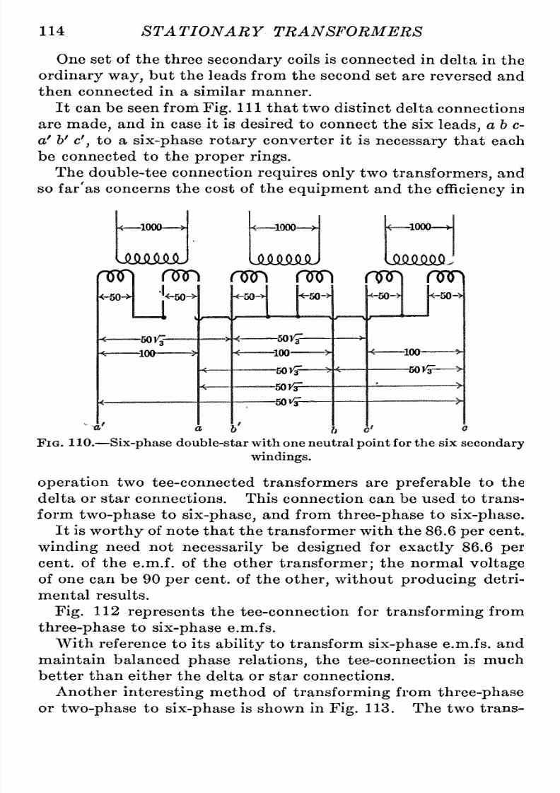
8/11/2019 Transformer Practice 1000194704
http://slidepdf.com/reader/full/transformer-practice-1000194704 126/290
114
STATIONARY
TRANSFORMERS
One
set
of the
three
secondary
coils
is
connected
in
delta
in the
ordinary
way,
but the leads
from the second
set
are
reversed and
then connected
in
a
similar
manner.
It
can
be
seen
from
Fig.
Ill
that
two
distinct
delta
connections
are
made,
and in
case
it is desired
to
connect
the
six
leads,
ab
c-
a'
h' c'
,
to
a
six-phase
rotary
converter it is
necessary
that each
be
connected
to
the
proper
rings.
The
double-tee
connection
requires
only
two
transformers,
and
so
far'as
concerns
the
cost
of the
equipment
and the
efficiency
n
-1000
-1000
-1000
UMMiU
UMMiU UM^
n^
nyn
nnn
n)Fi
cw\
nJFi
-50-H
^-M
'V
-50
VJ-
-100
-50-
^50-
-501^
-100
-50 S^
-50F3=-
-50VsP-
-50-
-50-
-100-
-50
vF-
FiG.
110.
Six-phase
double-star
with
one
neutral
point
for the
six
secondary
windings.
operation
two
tee-connected
transformers
are
preferable
to
the
delta
or
star
connections. This connection
can
be
used
to
trans-orm
two-phase
to
six-phase,
nd
from
three-phase
to
six-phase.
It
is
worthy
of
note
that
the transformer
with
the
86.6
per
cent,
winding
need
not
necessarily
be
designed
for
exactly
86.6
per
cent,
of the e.m.f. of the other
transformer;
the normal
voltage
of
one can
be
90
per
cent,
of
the
other,
without
producing
detri-ental
results.
Fig.
112
represents
the
tee-connection
for
transforming
from
three-phase
to
six-phase
e.m.fs.
With
reference
to
its
ability
to
transform
six-phase
e.m.fs.
and
maintain
balanced
phase
relations,
he tee-connection is
much
better
than
either
the delta
or
star
connections.
Another
interesting
ethod
of
ti'ansforming
from
three-phase
or
two-phase
to
six-phase
is shown in
Fig.
113.
The
two
trans-

8/11/2019 Transformer Practice 1000194704
http://slidepdf.com/reader/full/transformer-practice-1000194704 127/290
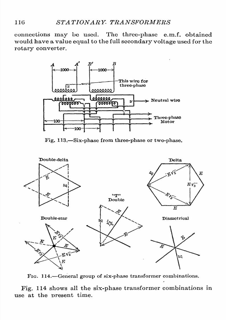
8/11/2019 Transformer Practice 1000194704
http://slidepdf.com/reader/full/transformer-practice-1000194704 128/290
116
STATIONARY
TRANSFORMERS
connections
may
be
used.
The
three-phase
e.m.f.
obtained
would
have
a
value
equal
to
the
full
secondary
voltage
used for
the
rotary
converter.
a'
B'
-1000-
JiMfiikilQ.
-1000-
\smmmj
-This
wire
for
three-phase
I
\mEm
Tnnnjwrsr-,
-100-
-100-
-u
3
'n
Neutral
wire
.j^
Three-phase
V
Motor
Fig.
113.
Six-phase
from
three-phase
or
two-phase.
Double-delta
'1
Delta
Fig.
114.
General
group
of
six-phase
transformer
combinations.
Fig.
114
shows
all
the
six-phase
transformer
combinations
in
use
at
the
present
time.

8/11/2019 Transformer Practice 1000194704
http://slidepdf.com/reader/full/transformer-practice-1000194704 129/290
CHAPTER
VIII
METHODS
OF COOLING TRANSFORMERS
Small
transformers
do
not
require
special cooling
devices since
they
have
large
radiating
surface
compared
with their losses.
Large
transformers
will
not
keep
cool
by
natural
radiation;
some
special
cooling
devices
must
be
provided.
The
various
cooling
methods
are:
Self-cooling
dry
transformers.
Self-cooling
oil-filled
transformers.
Transformers
cooled
by
forced
current
of air.
Transformers
cooled
by
forced
current
of water.
Transformers
cooled
by
forced
current
of
oil.
Transformers
cooled
by
some
combination
of above
means.
Self-cooling
Dry
Transformer.
^Transformers of
this kind
are
usually
of small
output,
and do
not
require
any
special
means
of
cooling,
the natural radiation
being
depended
upon
for
cooling.
Self-cooling
Oil
Transformers.
^This
arrangement
is
employed
for
at
least
60
per
cent,
of transformers
in
use,
the
core
and
coils
being
immersed
in
oil.
The
two
advantages
gained
by
immersing
these
transformers
in
oil,
are:
Insulation
punctures
can
in
many
cases
be
immediately repaired
by
the
inflow
of
oil,
and the
temperature
is reduced
by
ojfifering
eans
of
escape
for
the
heat.
Many
manufacturers
depend
upon
the
high
insulating qualities
of
the
oil
itself,
and, therefore,
introduce
less
insulating
material
such
as
cambric
and
mica,
etc.
On
the other hand
if
oil
is
punc-ured
it
will
close
in
again,
unless
the
puncture
be the
result
of
a
short-circuit in
the
transformer,
in
which
case an
explosion
is
liable
to
occur,
or
a
fire
started.
In this
way
electric
plants
have
been
destroyed.
For the
purpose
of
obtaining
the
necessary
radiating
surface,
tanks
of
the
large
self-cooled
transformers of
many
manufacturers
are
made
of
thin
corrugated
steel
or
cast
iron.
The
thin
cor-ugated
steel metal
tanks
are
not
sufficiently
strong
to
be
safely
handled in
transportation
with the
transformers
in them. A
slight
blow
is
sufficient
to
cause
the
oil
to leak
at
the
soldered
117

8/11/2019 Transformer Practice 1000194704
http://slidepdf.com/reader/full/transformer-practice-1000194704 130/290
118
STATIONARY
TRANSFORMERS
seams
between
the
different
sheets
of
thin
steel,
r
at
the
joints
between
the
sides.
The
cast-iron
case
is
unquestionably
the
best,
and the
most
suitable
for
oil
transformers;
the
great
strength
and
stability
of
cast-iron
cases
insure the safe
transportation
of
the transformer.
In the
design
of
oil-insulated
transformers,
interior
ventilation
is
provided
by
oil
passages
or
ventilating
ducts,
between the
coils,
nd
in
the iron.
These
secure an even
distribution
of heat
and
a
uniformity
of
temperature
throughout
the
transformer,
results
which
can
be secured
only by
a
free
internal
circulation
of
oil.
Without
good
oil
circulation,
ransformers
of
large
size
may
reach
an
internal
temperature
greatly
in
excess
of
that
of
the
external
surface
in
contact
with
the
oil,
and
in
poorly
designed
transformers
this
may
lead
to
the
speedy
destruction
of
the insu-ation
of the coils.
The
number and
size
of
the
oil
passages,
or
ventilating
ducts
are
planned
to
keep
all
parts
of the transformer about
evenly
cooled.
Such ducts
necessarily
use
much
available
space
and
make
a
transformer
of
a
given
efficiency
ore
expensive
than
if
the
space
could be
completely
filled
with
copper
or
iron.
Experience
with
oil-insulated
transformers of
large
size
and
high
voltage
has
shown that
oil increases
the
life
of the
insulation,
n
addition
to
acting
as a cooling
medium,
and
adds
materially
to
the
capability
of the transformer
to
resist
lightningdischarges,
in other
words
such
a
transformer
is
safer
than
a
dry
transformer.
The
amount
of heat
developed
in
a
transformer
depends
upon
its
load
and
its
efficiency.
In
a
500-kw.
transformer
of
98.5
per
cent,
efficiency
here
is
a
loss
at
full load
of
7.0 kw.
Since
this
loss
appears
as
heat,
it
must
be
disposed
of
in
some
way
or
the
temperature
will rise
until it
becomes
dangerously
high.
The
self-cooled oil-insulated
transformer
is now
made
in sizes
up
to
3000
kv-a
capacity
and
represents
one
of the
best
advances
in
the
manufacture
of
transformers.
This
new
design
is
a
very
important development
of
the
art
of transformer
manufacture.
This
type
will
be
more
in
demand
than the air-cooled
type
(air-
blast)
where
water
is
or
is
not
available,
s
expensive
or
not
suffi-ient.
It
requires
a
minimum
amount
of
attention
and
no
auxiliary
apparatus
or
equipment.
The
great
problem
to
be
solved
in this
type
was
that
of
providing
sufficient
surface
to
radiate
the heat
generated
and
keep
the
temperature
rise
within

8/11/2019 Transformer Practice 1000194704
http://slidepdf.com/reader/full/transformer-practice-1000194704 131/290
METHODS
OF COOLING
TRANSFORMERS 119
certain
limits.
The
total
amount
of surface broken
up
into
corrugationsdepends
on
its
efficiency
hich
may
be
defined
as
the
watts
radiated
per
square
inch
of
surface,
as
well
as on
the
amount
of heat
to
be
radiated.
A
plain
surface
is
found
to
be
the
most
efficient
as
both the
air
and
oil
come
into
close
contact
with
it,
but
as
it
is
broken
up
into
corrugations,
he
efficiency
s
decreased
slightly.
The
most
modern
self-cooled
type
is
pro-ided
with
auxiliary
pipes
or
radiators
whereby
the
actual
surface
of
the tank
can
be
greatly
increased
and
at
the
same
time
the
radiatingefficiency
f the surface
kept
very
high.
The method
of
cooling
consists
essentially
of
fitting
the
outside
of
a
plain
cast-iron
or
plain
boiler-plate
ank
with
a
number
of
vertically
arranged tubes,
the
upper
ends
of
which
enter
the
tank
near
the
top
and the
lower
ends
near
the
bottom.
An
idea
of
the
limitations
in this direction
can
be best obtained
by
making
a
rough comparison
of
two
transformers
of
widely
different
kv-a
capacities.
Assume for
a
small
transformer
100 kv-a
capacity,
and for
a
large
transformer
one
of
4000
kv-a
capacity.
Now,
if
the
same
densities obtain in
both
copper
and
iron,
namely,
if
the
larger
transformer
has
losses
proportional
to
the
increase in
output,
the
losses
will
be
increased
4000-^100 =
40
times,
while
the
area or
surface
of
radiation
would
only
be
increased
about
one-fourth
as
much
as
the
losses.
From
this
method
of
comparison
it is
seen
that
in
order
to
keep
the
heating
within
proper
limits it is
necessary
considerably
to
increase
the
size
of the
transformer,
resulting
in
a
cost
very
much
greater
than that of
a
transformer
having
auxiliary
eans
of
cooling.
For
this
reason
self-cooled
oil-insulated
transformers
are
not
generally
manufactured
in
sizes
above
2000
kv-a.
For
sizes
up
to
about
500
kv-a,
the
tank
is
single
corrugated
and above this size
compound corrugations
are
used
to
obtain the
necessary
radiating
surface.
Hot air
tends
to
flow
upward,
so
that,
in
providing
for
station
ventilation,
it is essential
that
the
inlet
of the
cool
air
should
be
low
down
and the outlet
somewhere
near
the
roof,
the
inflow
and
outflow
of
air
being
well
distributed
about the
station.
Self-cooled oil-insulated
transformers of
large
size
should
be
given
good
ventilation
or
else
the
life
of the
transformer
will
be
shortened.
The
first
indication
of
increased
temperature
will
be
darkening
of
the
oil
and
a
slight
deposit
on
the
inside
surfaces

8/11/2019 Transformer Practice 1000194704
http://slidepdf.com/reader/full/transformer-practice-1000194704 132/290
120
STATIONARY
TRANSFORMERS
of the
transformer.
Once
this
deposit
begins
to
form
the
tend-ncy
is
quickened
because
of the decreased
efficiency
f heat
dissi-ation
from the
transformer.
In
this
type
of
transformer the
only
remedy
where
the oil
has
thickened
to
a
considerable
extent
and
a
deposit
accumulated,
is
to
thoroughly
clean
the transformer
by
scraping
off
the
deposit
and
washing
it
out
with oil
under
high
pressure.
Transformers
Cooled
by
Forced Current
of Air.
^This
type
of
transformer
is
commonly
called
the
air
blast,
and
may
be
wound
for
any
desired
voltage
not
exceeding
40,000.
Air-blast
transformers
are
cooled
by
a
blast
of
air
furnished
by
a
blower.
The
blower
may
deliver
air
directly
into
a
chamber
over
which
the
transformer
is
located,
or
if
it
is
more
convenient,
the
blower
may
be located
at
a
distance
from the
transformer,
feeding
into
a
conduit which
leads to
the
air
chamber.
The
blower
is
usually
direct connected
to
an
induction
motor,
though
it
may
be
driven
by
other
means.
One
blower
generallysupplies
a
number
of
transformers in
the
same
station,
and the
transformers
are
usually
spaced
above
an
air
chamber,
in which
a
pressure
is
maintained
slightly
above that
of
the
surrounding
air.
The
air
for
cooling
the
iron
passes
from
the
lower
housing
selected
to
suit
the
transformer
capacity.
When
the
efficiency
f
an
air-blast
transformer
is
known,
an
approximate
estimate
of the
amount
of
air
required
can
be
made
by allowing
150
cu.
ft. of
air
per
minute
for each
kilowatt lost.
For the
most
satisfactoryoperation,
the
velocity
of
the
air
in
the chamber
should be
as
low
as
possible,
and
should
never
exceed 500 ft.
per
minute.
That
is,
the
cross-section
of
the
chamber
in
square
feet
should
at least
be
equal
to
the
number
representing
the total
volume of
air
required
per
minute
by
the
transformer,
divided
by
500.
The
power
required
to
drive
the blower for
furnishing
air
to
the transformers
is
so
small
as
to
be
practicallynegligible,
amounting
in
most
cases
to
only
a
fraction of
1
per
cent,
of the
capacity
of
the
transformers.
The
three-phase,
air-blast
shell-type
ransformer,
when delta
connected,
has
the
same
advantage
as
three
single-phase
trans-ormers
of the
same
total
rating
that
is,
by disconnecting
and
short-circuiting
oth
windings
of
a
defective
phase,
the
trans-ormer
can
be
operated
temporarily
at
two-thirds,
or
thereabout,
of the total
capacity
from
the
two
remaining windings.
Coming
under
this
heading
of
transformers cooled
by
forced

8/11/2019 Transformer Practice 1000194704
http://slidepdf.com/reader/full/transformer-practice-1000194704 133/290
METHODS OF
COOLING
TRANSFORMERS
121
current
of
air,
there
exist
two
methods,
viz.,
oil-insulated
trans-ormers
cooled
by
means
of
an
air-blast
on
the
outside
of the
tank,
and those in which the
air is
forced
directly
between
the
coils,
and
through
ducts
in
the
laminations.
The
forced
air-cooled
transformer
may
be
of
the shell
type
or
core
type,
but
preferably
of the
former for
large
or
moderate
sizes.
The
question
of
air-blast
against
oil-cooled
transformers
has
been
settled
in
practicelong
ago
in favor
of
the oil-cooled
type.
Some
of
the
chief
advantages
claimed
are
the
additional
safety
due
to
the
presence
of
the
oil
round the
windings,
and the
exclu-ion
of
a
forced
current of
air
and
consequently
exclusion
of
dirt
and
dust
from
all
parts
of the
windings.
Three-phase
transformers
require
larger
air
chambers than
single-phase
ransformers
of the
same
total
capacity.
The
tem-erature
of
the
out-going
air
compared
with
the
temperature
of
the
in-going
air is
the
best
indication
whether
sufficient air is
passing
through
the
transformers,
but
in
general,
and
on
the
basis
of 25
C,
the best
results
are
obtained
when the
temperature
of
the
incoming
air is
not
greater
than
this
value.
Depending
on
the
temperature
of the
surrounding
air
or
entering air,
the
out-oing
air
will
leave the transformer
greater
or
smaller
as
the
case
may
be.
Also,
depending
on
the
design,
the
difference
in
temperature
of
the
supply
of
air
and
the
air
leaving
the
trans-ormer
will
vary
between 12
and 20
C.
The insulation
of
air-blast
transformers
must
be
impervious
to
moisture,
and
must
have
superior
strength
and
durability.
It must also
permit
the
ready
discharge
of
the heat
generated
in
the
windings,
as
otherwise
the
transformer
temperature
may
reach
a
value
high
enough
to
endanger
the
lifeof
the
insulation.
In
building
such
a
moisture-proofinsulation,
he
coils
are
dried
at
a
temperature
above the
boilingpoint
of
water,
by
a
vacuum
process
which
thoroughly
removes
all
moisture.
After
a
treat-ent
with
a
specialinsulating
material,
they
are
placed
in
drying
ovens,
where
the
insulating
coating
becomes
hard
and
strong.
Then
the
coils
are
taped
with
an
overlapped covering
of
linen
and
again
treated and
dried,
there
being
several
repetitions
f
the
process,
depending
on
the
voltage
of
the
transformer.
The
insulating
materials
are so
uniformly
applied
and
the
varnish
so
carefully
compounded
that the
completed
insulation
on
the
coils
is
able
to
withstand
potentials
two
or
three
times
greater
than
the
same
thickness
of
the
best
insulating
il.

8/11/2019 Transformer Practice 1000194704
http://slidepdf.com/reader/full/transformer-practice-1000194704 134/290
122
STATIONARY
TRANSFORMERS
Transformers
Cooled
by
Forced
Current
of
Water.
This
type
of
transformer
is
usually
called
oil-insulated,
ater-cooled.
Inside
the
cast-iron tank
and
extending
below the
surface
of the
oil,
re
coils
usually
of seamless
brass
tubing
through
which
the
cooling
water
circulates.
These
coils
are
furnished with
valves
for
regulating
the flow
of
water,
and the
proper
adjustment
having
once
been
made,
the
transformer
will
run
indefinitely
with
practically
o
attention.
Another method
of
cooling
is
by
drawing
off
the
oil,
cooling
it,
and
pumping
it
back,
the
operation
being
continuous.
In
the
design
of
oil-insulated,
ater-cooled
transformers,
interior ventilation is
provided by
oil
passages
between
the
coils,
nd
in
the
iron.
These
secure an
even
distri-ution
of
heat and
a
uniformity
of
temperature
throughout
the
transformer.
Without
good
oil
circulation,
transformers
of
large
size
may
reach
an
internal
temperature
greatly
in
excess
of
that of the
external
surface
in
contact
with
the
oil.
As
a
means
of
securing
the best
regulation,
il
insulation is of
immense
advantage
inasmuch
as
it
permits
close
spacing
of
the
primary
and
secondary
windings.
It effects
great
economy
of
space,
and
its
fluidity
and
freedom
from
deterioration
greatly
assist
in
solving
the
difficult
problems
of transformer
insulation.
Its
good
qualities
come
into
play
with
remarkable
advantage
in
building
high-potential
transformers.
Water-cooling
coils
are
made of seamless
tubing
capable
of
with-tanding
a
pressure
of from 150
to 250
pounds
per square
inch.
Transformers Cooled
by
a
Combination
Method.
^Transformers
cooled
by
this
method
require
the
service of
a
pump
for
circu-ating
the
oil.
The
oil
is
forced
upward through
spaces
left
around
and
between
the
coils,
verflows
at
the
top,
and
passes
down
over
the
outside
of the
iron laminations.
With
such
a
scheme
trans-ormers
can
be
built
of much
largercapacities
han
the
largest
existing
water-cooled
transformers of the
ordinary
type,
without
such
increase in size
as
to
show
prohibitive
cost
and
to
necessitate
transportation
of
the transformers
in
parts
for
erection
at
the
place
of
installation.
The
forced-oil
system
allows the
circulation
of
the
oil
to
be
increased
to
any
extent,
thereby producing
a
rapid
and
positive
circulation
which
greatly
increases the
cooling
efficiency
of the
fluid.
Moreover,
this
method
of oil circulation
ensures
such
uniform
and
positive
cooling
that much
higher
indicated
temperatures
may
safely
be
permitted
in
transformers
operating
at
moderate
overloads.

8/11/2019 Transformer Practice 1000194704
http://slidepdf.com/reader/full/transformer-practice-1000194704 135/290

8/11/2019 Transformer Practice 1000194704
http://slidepdf.com/reader/full/transformer-practice-1000194704 136/290
124
ST
A
TIONARY
TRANSFORMERS
above
a
certain
given
value
in the
transformer.
This
outfit is
shown
in
Fig.
115
and
consists
of
a
water
relay
or
balance
which
is
actuated
by
a
volume
of
water
in
such
a
manner
that if
the
water
slacks
off
or
ceases
to
flow,
it
will
light
the
incandescent
lamp
shown.
The bell
alarm
is
so
arranged
that it
will
operate
as
soon
as
the
temperature
of
the
transformer,
as
indicated
by
the
thermometer,
reaches
a
certain
limit.
In
the
water-cooled
transformer,
the
heat
generated
by
losses
is
disposed
of
as
above
mentioned,
and
the
arrangement
is
so
Lamp
0
K ^
Low
VoltapJe
elay
Th
?rmometer
Resistance
-x:(^
Water
Relay
Fig. 115.
Water,
thermometer,
and
bell
danger
indicator
for
large
high-
voltage
power
transformers.
effective
that
but
very
little
heat
is
dissipated
from
the
tank and
consequently
no
advantage
is derived
from the
use
of
corrugated
tanks.
There
are,
however,
installations
of
transformers
where
a
satisfactory
upply
of
cooling
water
is
not
available
at
all
periods,
and
also
cases
where
the
meter
rate
of
cooling
water
is
excessive,
in
which
cases a
tank
with
corrugations
may
be
used.
The
usual
design
of
a
tank
with
corrugationsprovides
for
approxi-ately
70
per
cent,
of total
capacity
without
cooling
water.
Its
cost
is,
in
general,
about 10
to
15
per
cent,
greater
than
a
standard
boiler-iron
tank.
This
corrugated
type
has
been
used
to
advantage
in
very
cold
climates
where
water-freezing
diffi-ulties
are
common.
Fig.
116 shows
the
result of
cutting
off the
water
supply
of
a
water-cooled
transformer.
A
five-hour
duration
has resulted
in
a
temperature
rise
of
35
C.
(60
25
=
35
C),
while
a
two
and
one-quarter
hour
duration
shows
an
increase in
temperature
of
17
C.
(57-40
=
17
C).
The
cooling
coil
of this
type
of
transformer
is
sometimes

8/11/2019 Transformer Practice 1000194704
http://slidepdf.com/reader/full/transformer-practice-1000194704 137/290
METHODS OF
COOLING TRANSFORMERS
125
coated
on
the
outside with
a
deposit
from
the
oil while
the
inside
is
lined
by
impurities
n
the
cooling
water,
A
good
method
of
cleaning
the
inside
of
cooling
coils is
to
pour
equal
parts
of
hydrochloric
acid
and
commercially
pure
water
into
the
coil. After
the
solution has
been
standing
for
about
one
hour,
flush the
coils
out
thoroughly
with
clean
water.
When
deposit
has
accumulated
on
the
outside
of
the
cooling
coil,
it
is
necessary
to
remove
it
from
the
tank
for
cleansing.
The
deposit
can
be
wiped
or
scraped
off.
Sometimes moisture
is
condensed
at
the
top
of
this
type
transformer when
located
in
a
damp
atmosphere.
To
avoid
this,
the
transformer
should
be
kept
warm;
that
is,
the
tempera-ure
of the
oil
should
never
go
below
10
C.
In
some
cases
a
form
of breather
has
been
used,
which consists
of
a
vessel
of
chloride
of
calcium,
so
arranged
as
to
allow
the
water taken
out
of the
air
to
drain
off
without
mixing
with
the
air
that
is
going
in
on
account
of
the
contraction
of
the
transformer
oil in
cooling.
An
indica-ion
of condensation
of
moisture is
the
accumulation of
rust
on
the
underside
of
the
transformer
cover
at
the
top.
On
all
large
high-voltage
transformer
installations
provision
should be
made for continuous
sampling
and
filtration of the
oil in
any
transformer
without
removing
the
unit
from
service.
This
is
usually
done
by
means
of valves
at
the
bottom
and
top
of transformer tank
and
withdrawing
the
oil
and
filtering
t
by
forcing
it,
at
a
200-lb.
pressure,
through
a
series
of
about
twenty-
five
filter
sections,
ach
containing
five
8-in.
by
8-in.
filter
papers,
making
a
total
thickness
of almost
0.75
in. of
paper.
The
paper
filters
the
oil
and
removes
all
moisture,
returning
it
to
the
tank
dry
and
clean.
The
capacity
of
oil-containing
anks
should
not
be
less than the
oil
capacity
of
any
one
transformer,
but
prefer-bly
slightly
reater
in
capacity
than
the
largest
transformer
in
the
station.
About
four hours should be
sufficient
to
filter
the
entire
contents
of
any
transformer and
on
this
basis
the
capacity
of
a
filter
equipment
may
be
provided
for.
TEMPERATURE
DISTRIBUTION
Core-t3rpe
(vertical
cylindrical
oils,
turns
of
the
conductor
being
in
a
horizontal
plane).
With
this
type
of
winding
the
ends
of
the
coils will be somewhat
cooler, owing
to
the
heat
which
passes
out
at
those
points.
If the
temperature
of the
oil
adjacent
to
the
top
portion
of
the
coils is
much
higher
than
at

8/11/2019 Transformer Practice 1000194704
http://slidepdf.com/reader/full/transformer-practice-1000194704 138/290
126
STATIONARY TRANSFORMERS
the
bottom,
there
will
be
a
tendency
to
transmit
heat
downward
in
the
coil.
The
heat
transmitted will
be
small,
but
the
thermal
resistance is
high
as
compared
with
the
temperature
difference
in this
direction.
The
most
important
result
will
be
that
the
temperature
of
the
top
portion
of the
coil
will
be
almost
as
much
higher
than the
temperature
of
adjacent
oil
as
that
of
the
80
40
30
H
80
I
70
60
50
40
30
no
W
(a)
Temperature
of high
voltage
winding by
reslatance
.
(6)
low
thermometer.
i-c)
high
(.d)
oil.
(^)
water
leaving
cooling
coil
.
0
7 8a
Hours
Run
Fig.
116.
10
11
18
13
14
bottom
portion
is
above the
oil
adjacent
to
it,assuming,
of
course,
that
the
equivalent
thermal
resistance
from
the
coil
to
the
oil is
practically
uniform
throughout
the
length
of the
duct.
The
total
average
temperature
of
the
coil
is therefore
related
not to
the surface
temperature
at
the bottom
of the
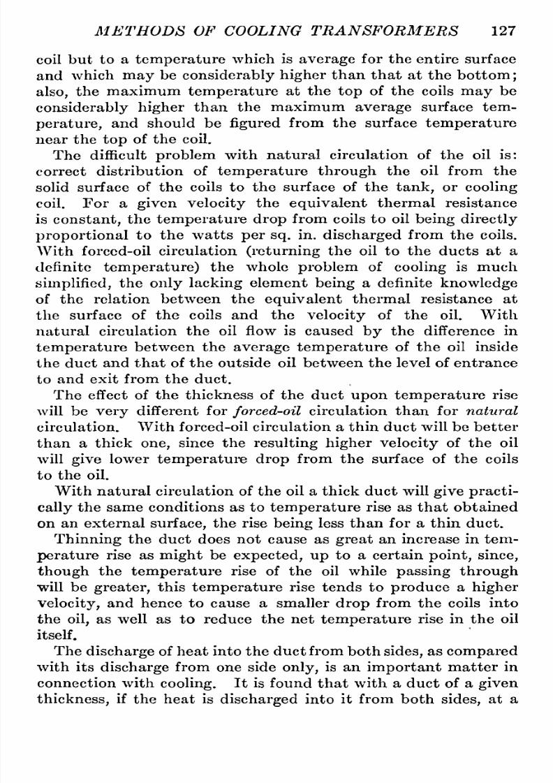
8/11/2019 Transformer Practice 1000194704
http://slidepdf.com/reader/full/transformer-practice-1000194704 139/290
METHODS OF
COOLING
TRANSFORMERS
127
coil
but
to
a
temperature
which
is
average
for the
entire
surface
and
which
may
be
considerably
higher
than that
at
the
bottom
;
also,
the
maximum
temperature
at
the
top
of the
coils
may
be
considerably
higher
than the
maximum
average
surface
tem-erature,
and
should be
figured
from
the surface
temperature
near
the
top
of
the
coil.
The difficult
problem
with
natural
circulation
of
the
oil is:
correct
distribution
of
temperature
through
the
oil
from the
solid
surface
of the coils
to
the
surface of the
tank,
or
cooling
coil.
For
a
given
velocity
the
equivalent
thermal
resistance
is
constant,
the
temperature
drop
from
coils
to
oil
being directly
proportional
to
the
watts
per sq.
in.
discharged
from
the
coils.
With
forced-oil
circulation
(returning
the
oil
to
the ducts
at
a
definite
temperature)
the
whole
problem
of
cooling
is much
simplified,
he
only
lacking
element
being
a
definite
knowledge
of
the
relation
between the
equivalent
thermal
resistance
at
the
surface
of the
coils
and
the
velocity
of
the
oil.
With
natural circulation
the
oil
flow
is
caused
by
the difference in
temperature
between
the
average
temperature
of
the
oil inside
the duct
and
that
of the
outside oil
between
the level of
entrance
to
and exit from the
duct.
The
effect of the
thickness
of
the
duct
upon
temperature
rise
will
be
very
different
for
forced-oil
circulation
than for
natural
circulation.
With forced-oil circulation
a
thin
duct
will
be better
than
a
thick
one,
since
the
resulting
higher velocity
of
the oil
will
give
lower
temperature
drop
from
the
surface of
the
coils
to
the
oil.
With
natural
circulation
of
the
oil
a
thick
duct
will
give
practi-ally
the
same
conditions
as
to
temperature
rise
as
that
obtained
on
an
external
surface,
the rise
being
less than
for
a
thin
duct.
Thinning
the duct does
not
cause as
great
an
increase in
tem-erature
rise
as
might
be
expected,
up
to
a
certain
point,since,
though
the
temperature
rise
of the
oil
while
passing through
will
be
greater,
this
temperature
rise
tends
to
produce
a
higher
Velocity,
nd
hence
to
cause
a
smaller
drop
from
the
coils
into
the
oil,
as
well
as
to
reduce
the
net
temperature
rise in
the
oil
itself.
The
discharge
of heat
into
the duct
from
both
sides,
s
compared
with its
discharge
from
one
side
only,
is
an
important
matter
in
connection with
cooling.
It
is
found
that with
a
duct of
a
given
thickness,
if
the heat
is
discharged
into it
from both
sides,
at
a

8/11/2019 Transformer Practice 1000194704
http://slidepdf.com/reader/full/transformer-practice-1000194704 140/290
128
STATIONARY
TRANSFORMERS
given
density
in
watts
per
sq.
in,,
both
the
temperature
rise of
the
oil
while
passing
through
the
duct,
and
the
temperature
rise
of
the
coils
above
adjacent
oil,
will
be
smaller
than
if
the
heat
is
discharged
into
one
side
of
the duct
only,
at
the
same
density.
Thus
twice the heat is
carried
away
by
the
duct,
with
a
smaller
temperature
rise.
This smaller
temperature
rise of
the
oil
while
passing
through
the
duct,
though absorbing
twice
the
heat,
indicates
that
the
velocity
of
flow
is
more
than
double,
and
this
accounts
for
the reduced
drop
from
the
coils into
the
oil. The
great
difference in
velocity
in
the
two
cases
is
accounted
for
by
the
friction
on
the
side
of
the duct
where
no
heat is dis-harged,
which is
much
greater
than when
heat
is
being
discharged.
Shell
type
(vertical
oil-ducts
between
flat
coils).
With
this
type,
in
general,
the
larger
insulation
is
not
in
the
path
of heat
flow,
and the
insulatingcovering
is
thin.
The
equivalent
ther-al
resistance is
uniformly
distributed
throughout
the
length
of
the
duct,
since
the
rate
of
oil
flow
is
the
same
throughout,
but
this resistance
will
change
with
changes
in
the
rate
of heat
discharge
because the
velocity
of
the
oil
will
be
different.
If
the
heat
generated
in
any
part
of
the surface
which is
opposite,
the
oil
would
receive heat
at
a
uniform
rate
throughout
its
passage
through
the
duct,
and
the
difference
between
the
temperature
of
the coil and that of
the
oil
would be the
same
at
the
top
as
at
the
bottom.
The
temperature
at
the
top
part
of the coil would
be
as
much
greater
than
its
temperature
at
the bottom
as
the
temperature
of
the
oil
leaving
the duct
is
greater
than
its
tempera-ure
at
entrance.
This
would
result
in the
passage
of
a con-iderable
portion
of
heat
downward
through
the
copper,
which
is
a
good
conductor
of
heat,
the effect
being
that
more
heat
is
discharged
per sq.
in.
from
the
bottom
part
of
the
coil
than
from the
top.
The
temperature
rise
of the
oil
in its
passage
through
the
duct
is
more
rapid
in
the
bottom
portion
of the duct
than
at
the
top,
and
the
temperature
drop
from
the
oil is
also
greater
in
the
bottom
portion
of the
duct than
at
the
top.
The
temperature
gradient
in the
copper
from the
top
of the
coil
to
the bottom
isthus
reduced,
giving
a
more
uniform
temperature,
as
well
as a
lower
average
temperature.
On
the
other
hand,
though
the
temperature
of
the
oil where it
leaves
the
duct
would
be
the
same,
if
its
velocity
were
the
same,
since
it
absorbs
the
same
total
heat,
yet
its
average

8/11/2019 Transformer Practice 1000194704
http://slidepdf.com/reader/full/transformer-practice-1000194704 141/290
METHODS
OF
COOLING
TRANSFORMERS
129
temperature
throughout
the
duct
will
be
greater
on
account
of
the
larger
proportion
of heat
which
it
receives
near
the
bottom.
This will
result in
an
increase in the
velocity
of
circulation,
hich
tends
to
reduce
both
the
temperature
rise
of the
oil
in
the
duct
and
the
temperature
drop
from
the
coil into
the
oil,
both
of these
actions
affecting
further
reduction in
the
temperature
of the
coils.
Disc-shape
Coils
(horizontal
position
with horizontal
ducts
between).
These
coils
may
be
wound
either
in
single
turn
layers,
or
with
several
turns
per
layer.
In the former
case
practically
ll
the heat
will be
thrown
out
into
the
horizontal
ducts,
but
in
the
latter
the
inner
and
outer
layers
will
discharge
best
through layer
insulation
in the
inner
and
outer
cylindrical
surfaces.
A
large
portion
of the
heat
will
find
an
easier
passage
out
through
the
horizontal oil
ducts than from
layer
to
layer
in
the
coils.
The
relative
amounts
passing
out
through
the
two
paths
will
depend
upon
the
circulation
of the
oil.
If the
oil
is
stagnant
in
the
horizontal
ducts,
it
reaches
a
temperature
where
it
ceases
to
absorb
heat.
It
is
quite
evident
that
more
solid
matter
of the
hydrocarbons
will
deposit
at
those
points
of the
maximum
temperature;
that
is,
at
those
points
commonly
known
as
hot-spots.
If
80
per
cent,
of
the transformer
operates
at
a
temperature
of 40
C. and
the
remaining
20
per
cent,
at
80
C,
the
transformer
is
badly
designed
and the weakest
part
of
the
insulation
is
at
the
point
of
the
maximum
temperature
rise.
Therefore,
a
knowledge
of the
distribution
of
temperature
throughout
a
transformer,
and
of
the
various
things
which
effect
this
distribution,
s
important
from
the
standpoint
of
all
those who
operate
transformers;
and,
if
we are
to
avoid serious
trouble
with
transformers,
trouble
with
oil,
and
oil
depositing
which
necessitates
frequent
cleaning
out
of the
transformers,
it is
essential
there should be
no
hot-
spots.
Standard
heating
guarantees
for
self-oil-cooled,
ir-blast
and
water-cooled
transformers
are
given
in
the
following
table.
The
oil-cooled
transformer
measurements
are
based
on
the
surrounding
air
temperature
of 25
C. normal
condition
of
ventilation,
nd
a
barometric
pressure
of
760
mm.
of
mercury.
The
air-blast
transformer
measurements
are
based
on an
ingoing
air
temperature
of 20
C.
and
a
barometric
pressure
of
760
mm.
of
mercury.
9

8/11/2019 Transformer Practice 1000194704
http://slidepdf.com/reader/full/transformer-practice-1000194704 142/290
130
ST
A
TIONARY
TRANSFORMERS
TABLE II.
HEATING
GUARANTEES FOR
OIL-COOLED,
AIR-
BLAST
AND
WATER-COOLED
TRANSFORMERS
The
water-cooled
transformer
measurements
are
based
on
a
normal
supply
of
ingoing
water
at
a
temperature
of
15
C.
All corrections for
variations
in the
three
above
types
of
transformers
are
made
by changing
the observed
rise
of
tempera-ure
by
0.5
per
cent,
for each
degree
Centigrade
temperature
variation,
or
for
each
5
mm.
deviation
in
barometric
pressure.
TRANSFORMER
OIL.
As the
subjects
of
treating
transformer
oil
and
the
properties
of
oil
are so
broad,
and
have been
treated
in
a
thorough
manner
by
other
writers,only
a
few
important
notes
are
given
here.
The
most
important
characteristics
of transformer
oil
which
interest
the
operating engineer
are
summed
up
in
the
following
table.
TABLE
III

8/11/2019 Transformer Practice 1000194704
http://slidepdf.com/reader/full/transformer-practice-1000194704 143/290

8/11/2019 Transformer Practice 1000194704
http://slidepdf.com/reader/full/transformer-practice-1000194704 144/290
132
STATIONARY
TRANSFORMERS
Often
it
is
desired
to
determine
the
insulatingqualities
of
an
oil
when
there
are
no
high voltage
testing
transformer
and
apparatus
available
for
making
a
test.
When
this
is the
case,
a
very
good
idea of
the
insulatingproperties
of
the
oil
can
be
obtained
by
testing
for
the
presence
of
water
with
anhydrous
copper
sulphate.
To
prepare
the
anhydrous
copper
sulphate,
heat
some
copper
sulphate crystals
(blue-vitriol)
n
top
of
a
hot
stove.
The
heat
will
drive
out
the
water
of
crystallization,
leaving
as
a
residue
a
white
powder,
which
is known
as
anhy-rous
copper
sulphate.
Fill
a
test
tube
with
a
sample
of
the
oil,
dd
a
small
quantity
of
the
anhydrous
copper
sulphate,
and
shake
well.
If there is
any
moisture
present
in
the
oil,
it
will
combine with
the
anhy-rous
copper
sulphate,
forming
a
distinctly
lue
solution.
This
test
is
quite
delicate
and
a
very
small
quantity
of
moisture
can
be
detected
by
it.
If
this
test
does
not
show
the
presence
of
water
it
is
quite
safe
to
assume
that
the
insulatingproperties
of
the
oil
are
fairlyhigh.
When
obtaining
a
sample
of
oil for
testing,
always
get
the
sample
of
oil
from
the
bottom
of
the
tin
or
barrel,
because,
as
water
is
heavier
than
oil,
the
maximum
quantity
of
water
will
always
be
found
at
the
bottom.
To
obtain
a
sample
from
the
bottom,
use
a
long
glass
tube
of small
diameter,
hold
the
thumb
tightly
over
one
end
and
plunge
it
to
the
bottom
of
the
barrel.
Remove
the
thumb
letting
the
air
escape,
then
press
the
thumb
tightly
ver
the
end
of
the
tube
and
withdraw
it
with
the
sample
of
oil.
The
real
importance
of
the
light
oil
known
to
the trade
as
mineral
seal
oil
is
that it
tends
to
decrease
the
deposit
thrown
down
on
the
bottom
of
the
transformer
tank,
cooling-coils
and
the
transformer
coils themselves.
The
(A)
class
referred
to
here
is
a
dark-colored
oil
having
a
specificgravity
somewhat
higher
than
the
mineral
oil,
its
flash
and
fire
points
are
much
higher
but
when
subjected
to
continued
heating
it
throws
down
a
deposit
tending
to
clog
up
the oil
ducts
of
the
transformer
and
impede
the
circulation
of
the
oil.
So
far
as
is
known
this
deposit
is
caused
entirely
by
the
effect
of
the
heat
on
the
oil.
It
can
be removed
by
filtering
hrough
a
bed
of
lime
and
then
a
sand
bed,
or
preferablyby
using
one
of
the
oil-drying
outfits
now
on
the
market.
The
(B)
class
oil
is
light
and
practically
white,
and
is
usually
referred to
as
mineral
seal
oil;
it
has
rather
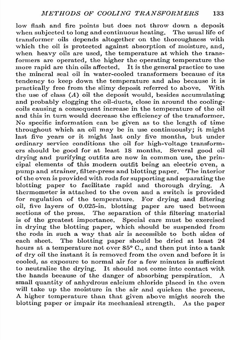
8/11/2019 Transformer Practice 1000194704
http://slidepdf.com/reader/full/transformer-practice-1000194704 145/290
METHODS OF
COOLING TRANSFORMERS
133
low
flash
and fire
points
but
does
not
throw down
a
deposit
when
subjected
to
long
and
continuous
heating.
The
usual
life
of
transformer
oils
depends
altogether
on
the
thoroughness
with
which
the
oil is
protected
againstabsorption
of
moisture,
and,
when
heavy
oils
are
used,
the
temperature
at
which the
trans-
formei*s
are
operated,
the
higher
the
operating
temperature
the
more
rapid
are
thin oils
affected.
It
is
the
generalpractice
o
use
the
mineral
seal
oil
in
water-cooled
transformers because
of
its
tendency
to
keep
down the
temperature
and also because
it is
practically
ree from
the
slimydeposit
referred
to
above.
With
the
use
of class
(A)
oil
the
deposit
would,
besides
accumulating
and
probably
clogging
the
oil-ducts,
lose
in
around
the
cooling-
coils
causing
a
consequent
increase in
the
temperature
of
the
oil
and
this in
turn
would decrease
the
efficiency
f
the
transformer.
No
specific
nformation
can
be
given
as
to
the
length
of
time
throughout
which
an
oil
may
be
in
use
continuously;
it
might
last
five
years
or
it
might
last
only
five
months,
but
under
ordinary
service conditions
the
oil for
high-voltage
transform-rs
should be
good
for
at
least
18
months.
Several
good
oil
drying
and
purifying
outfits
are now
in
common
use,
the
prin-ipal
elements
of
this modern
outfit
being
an
electric
oven,
a
pump
and
strainer,
ilter-press
nd
blotting
paper.
The
interior
of the
oven
is
provided
with
rods
for
supporting
and
separating
he
blotting
paper
to
facilitate
rapid
and
thorough
drying.
A
thermometer
is attached
to
the
oven
and
a
switch is
provided
for
regulation
of
the
temperature.
For
drying
and
filtering
oil,
five
layers
of
0.025-in.
blotting
paper
are
used
between
sections
of the
press.
The
separation
of
this
filtering
aterial
is
of
the
greatest
importance. Special
care
must
be exercised
in
drying
the
blotting
paper,
which
should be
suspended
from
the
rods
in such
a
way
that air
is
accessible
to
both
sides
of
each
sheet. The
blotting
paper
should be dried
at
least
24
hours at
a
temperature
not
over
85
C,
and then
put
into
a
tank
of
dry
oil
the
instant it is
removed from
the
oven
and before
it
is
cooled,
as
exposure
to
normal
air
for
a
few
minutes
is
sufficient
to
neutralize the
drying.
It
should
not
come
into
contact
with
the
hands
because of
the
danger
of
absorbingperspiration.
A
small
quantity
of
anhydrous
calcium
chloride
placed
in
the
oven
will
take
up
the
moisture in
the
air
and
quicken
the
process.
A
higher
temperature
than
that
given
above
might
scorch
the
blotting
paper
or
impair
its
mechanical
strength.
As the
paper

8/11/2019 Transformer Practice 1000194704
http://slidepdf.com/reader/full/transformer-practice-1000194704 146/290
134 STATIONARY
TRANSFORMERS
is
somewhat
weakened
by
saturating
with
oil,
it
should
be
care-ully
handled
after
removal
from the
bath.
A
tank of
suitable
size
for the
paper
should be filled
with
dry,
clean
oil
and
the
paper
should
be
submerged
in
the
oil.
The
paper
should
be
carefully
suspended
in
the
tank,
the
bottom
edge
of the
paper
being
kept
3
or
4
in.
from
the
bottom.
The
oil
level should
be
at
least
2
in.
above
the
top
of
the
paper.
A
strainer
is
provided
to
prevent
anything
of
appreciable
size
from
entering
and
in-uring
the
pump.
It
is
easily
accessible
and
should be
cleaned
occasionally.
The
rating
in
gallons
per
minute is
usually
for
average
conditions in
filtering
lean
heavy
oil
or
dirty
light
oil.
The
best
oil
temperature
for
filtering
s
between
25
and 75
C.
In
the
installation
of
this
outfit the
pump
should
be
placed
so
that
oil
falls
by
gravity
and
as
fast
as
the
pump
will
take
it.
With
clean
oil
the
pressure
and volume
will
remain
nearly
con-tant,
the volume
being
nearly
proportional
to
the
pressure,
but
with
dirty
oil
the
pressure
will increase
very
rapidly.
With
dirty
oil
and
paper
the volume
increases
much
more
slowly
than the
pressure
and
there
is
little
gained
by
an
increase
in
pressure
over
75
pounds
per square
inch.
In
general,
class
(B)
oil is
filtered
twice
as
fast
as
the class
(A)
oil,
and the
greater
capacity
is obtained
by frequent
renewal
of
paper,
the
total
capacity
per
day
depending
largely
on
the
time
consumed
in
the
operation.
In
placing
paper
in
the
press,
care
should
be taken
to
have the holes
in
the
paper
corresponding
with
those
in
the
plates.
Oil
is
admitted
at
any
pressure
not
over
100
pounds
per
square
inch.
The
pressure
will
at
first
be
very
low, gradually
increasing
as
the
paper
clogs
with dirt.
It is
found that
after
three
re-lacements
of
the
paper,
the
dielectric
strength
of the
oil is
apt
,to
fall
off,
and
that
it is
best
to
discard
the
full
charge
of
paper
and
begin again.
The
amount
of oilwhich
can
be
filtered
through
one
set of
papers
depends entirely
on
the
quality
and
tempera-ure,
hot
oil
being
filtered
with
great
facility
ecause
of
its
low
viscosity.
By
this
process
oil
may
be
dried
to
withstand
a
puncture
test
from
40,000
to
60,000
volts
with
a
standard
spark
gap
consisting
of
two
0.5
in.
diameter
discs
spaced 2/10
in.
apart.
With oil
of
an
average
quality
as
regards
moisture
and
foreign
matter
one
treatment
will
usually
remove
all
sediment
and
bring
the
puncture
voltage
to
40,000
volts
or
more.
Oil
which
has
been
damaged
by
overheating
from
continuous
over-oad
or
bad burn-out
may
be
treated
in
this
purifying
outfit,

8/11/2019 Transformer Practice 1000194704
http://slidepdf.com/reader/full/transformer-practice-1000194704 147/290
METHODS
OF COOLING
TRANSFORMERS
135
and
the
sediment
removed
although
the
oilwillstillbe
darker
in
color than it
was
originally.
If the
oil isthickened
to
a
slimy
nature,
it will
quicken
the
operation
to
heat
it
to
75
C.
just
before
running
it
through
the press.
Water- Parts
In
10,000
by
Volume
Fig.
117.
Curve
showing
the
effects
of
water
in
oil.
The
curve
Fig.
117
very
clearly
shows the
serious
effects
of
water
in
amounts
less
than
0.010
per
cent.
It shows
that
the
water
present
in
the
oil
must
not
exceed
0.001
per
cent,
in
order
to
obtain
a
dielectric
strength
of
40,000
volts in
the
standard
test
(0.2
in.
between
0.5
in.
disc).
1^

8/11/2019 Transformer Practice 1000194704
http://slidepdf.com/reader/full/transformer-practice-1000194704 148/290
CHAPTER
IX
CONSTRUCTION,
INSTALLATION
AND
OPERATION
OF LARGE
TRANSFORMERS
There
are
various
types
of transformers
on
the
market
differ-ng
so
much
in
design
that
it is difficult
to
tell
exactly
whether
they
are
of
one
or
the
other
design
(shell
or core
type)
;
in
fact,
what
some
manufacturers call
a
shell
transformer
others call
a
core-type
transformer.
However,
the
design
and
construc-ion
of
transformers
referred
to
here
are
strictly
of
the
core
and
shell
types
respectively,
of
high-voltage
large-capacity
design,
and
of
American
manufacture.
Transformers
are
always
sent
from the
factory
as
completely
assembled
in their
tanks
as
their size
and
transportation
facilities
in
the
countries
they
have
to
pass
through
will
warrant.
When
they
are
sent
disassembled,
which is
usually
the
case
if
they
are
for
very
high
voltages
and
large capacity,
the
tanks
are
usually
protected
for
shipment
abroad
but
left
unprotected
for
home
shipment;
the coils
are
carefully
packed
in
weatherproof
boxing,
and the
core
if
of
the shell
type
is
packed
in
strong
wooden
boxes
of moderate
size
(in
a
loose
state)
,
the
core
of
the
core
type
being shipped
already
assembled
each
leg
being
packed
in
one
box
and
the
end-laminations
in
separate
boxes. Whether the
transformer
is
built
up
at
its destination
or
sent
already assembled,
it should be
thoroughly inspected
before
being permanently
put
into
the
tank.
If
the transformer
is
sent
from
the
factory
in its
tank,
which
is
very
seldom
done,
it
should be
removed
and
thoroughly
inspected
and
cleaned
before
giving
it
a
heat-run.
Let
us
deal
first
with
the
core-type
transformer which
consists
essentially
of
two
or
three
cores
and
yokes
which
when
assembled
form
a
complete
magnetic
circuit.
These
cores
and
yokes
are
made
up
of laminated
stampings
which
vary
from
0.010
to
0.025
in. in
thickness
according
to
the
frequency
of
the
system
on
which
they
are
to
be
used
and
the different manufacturers.
The
laminations
are
insulated
from
each other
by a
coat
of
varnish
or
paper
to
limit
the
flow
of
eddy
currents.
It
is
shown
in
Fig.
1
18
that there
are
three
cores
of
equal
cross-
136

8/11/2019 Transformer Practice 1000194704
http://slidepdf.com/reader/full/transformer-practice-1000194704 149/290
CONSTRUCTION
OF
LARGE TRANSFORMERS
137
section
joined
by
a
top
and bottom
yoke
of
the
same
cross-section
as
the
cores,
and
that
upon
each
core
are
placed
the
low
and
high
voltage
windings
for
one
phase.
The low and
high voltage
windings
are
connected
so
that the fluxes
in
the
cores are
120
elec-rical
degrees apart,
making
their
vector
sum
equal
to
zero
at
any
instant.
The
usual
designs
of
core-type
transformers
made
by
the
best
manufacturers
have
a
uniform
distribution
of
dielectric
flux
between
high
and
low
voltage
windings,
excepting
at
the
ends of
Fig.
118.
Three-phase
core-type
transformer.
the
long
cylinders
here the
dielectric
flux
will be
greater
and
its
distribution
irregular.
As
already
stated,
the
core-type
transformer
has
its lamina-ions
shipped
already
assembled,
wrapped
in
insulating
aterial
of
horn-fiber
and
bound
with
strong
binding
tape
which
serves as
a
binding
to
keep
the
laminations
of
the
assembled
sections
intact. The
different
sections
are
assembled
on
wooden
pins
of
the
size
of
the
holes
in
the
laminations;
first,
n
one
direction,
and
then
this
end
in
the
oppositedirection,
lternating
spaces
thus
being
left for
assembling
the end
laminations.
The
approxi-ate
number of
laminations
per
inch
required
in
building
up

8/11/2019 Transformer Practice 1000194704
http://slidepdf.com/reader/full/transformer-practice-1000194704 150/290
138
STATIONARY
TRANSFORMERS
tliese
laininuted sections
may
be
detoniiiiied from
the
informa-ion
that
the
iron
solid,
would be about
90
per
cent,
of
the
height
of the built
up
laminations,
36
and
64
laminations
per
inch
being
about
the number
of
laminations
required
for
the
two
standard
thicknesses,
0.025
and
0.10
in.
respectively.
The
required
number
of
laminations
are
built
in
an
insulating
channel
piece,
and
on
the
top
of
the
channel
piece
and the
pile
of
lamina-ions
another
channel
piece
is
placed,
the whole
being
pressed
down
to
dimensions
and the
channel
pieces
stuck
together
with
shellac
under
the
influence of
pressure
and heat. The
various
sections
are
then
assembled
with
wooden
pins
to
hold them
together,
these
remaining
in
the holes
permanently,
and the
assembled
sections
clamped
to
dimensions
and
finally
wound
with
a
layer
of
strong
binding
tape
of
half-lap,
hich
should
not
extend
beyond
the
beginning
of
the
spaces
for the end-laminations.
The
core
is
now
built
up,
the
next
process
being
to
insert
the
end
laminations
at
the
bottom,
their
number
corresponding
to
the
spaces
left for
them, making
them
so
fit
into
the
spaces
as
to
form
butt-joints.
These
laminations
are
assembled
while
the
cores or
legs
are
resting
in
an
horizontal
position.
While
in
this
position
the bottom
clamp
with
its
insulation
is
fastened
over
the
end
laminations
and the
whole
raised
by
the
help
of
an-ther
clamp
and
cross-bars
to
a
vertical
position,
with
open
ends
upward.
The
clamping
bolts
are
then
placed
in
a
loose
state,
reliance
being
put
on
the
bolts
(which
hold the bottom
clamps
in
position)
to
keep
the
cores
in
a
vertical
position
during
the
assembly
of
coil-supports
and
coils.
The
coils,
which
are
of
a cylinder form,
are
raised
by
means
of
a
stout
tape
and
slipped
over
the
cores.
All of the
coils
which
connect
together
at
the
bottom
should be
connected immedi-tely
after
the
coils
are
in
position.
Between
the
cylinder
low-
voltage
coils
and the
high-voltage
coils is
placed
a
cylinder
shaped
insulating
separator,
the
separator
being
held
in
posi-ion
by
means
of
spacing
strips
of
wood. All
connections
be-ween
outside coils
can
be
conveniently
made before
the
spacing
strips
are
inserted
between
the
high
and
low-voltage
windings,
when the
coils
may
be
easily
turned
to
such
positions
s
will
leave the
coil
connections
as
distant
as
possible
from
the
side
of
the
steel tank.
The
top
connections
should
be made after
all
the
coils
of
the
high-voltage
winding
are
in
position.
A
press-
board
insulatingpiece
or
casing
is
finally
placed
over
the whole

8/11/2019 Transformer Practice 1000194704
http://slidepdf.com/reader/full/transformer-practice-1000194704 151/290

8/11/2019 Transformer Practice 1000194704
http://slidepdf.com/reader/full/transformer-practice-1000194704 152/290
140
ST A
TIONARY
TRANSFORMERS
order
of
assembly.
The
assembly
of
coils is
begun
in
an
hori-ontal
plane,
and
stacked
one
above
the
other
as
shown
in
Fig.
121,
the
outer
press-board
insulation
piece
being
set
on
two
wooden-horses, correctly
spaced,
depending
on
the
size of
the
transformer
to
be assembled.
The
first
coil,
aken
from
the
top
Fig.
119.
Three-phase
shell-type
transformer.
of the stack
is
placed
in
position
with
its inner
edges
insu-ated
by
means
of
channel-shaped
insulation
pieces.
Each
coil
before
it is
placed
in
the
assembly
has the
same
shaped
insula-ion
pieces
on
its
outer
edges;
insulation
separators
are
arranged
Fig. 120.
Single-phase
transformer
iron
assembly.
in
symmetrical
order
for
both
the low
and
high-voltage
coils
with
wooden
filling
locks and
channel
pieces
set at
the
inside
top
and bottom of coils. The
assembly
of
these
coils
if of
large
size
can
easily
be
lowered
into
position.
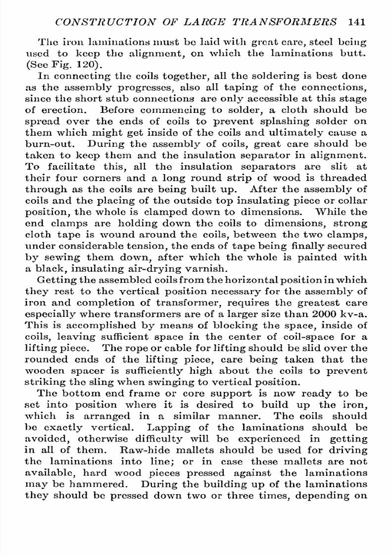
8/11/2019 Transformer Practice 1000194704
http://slidepdf.com/reader/full/transformer-practice-1000194704 153/290
CONSTRUCTION
OF
LARGE
TRANSFORMERS
141
Tlic
iron laminations
must
be
laid
with
great
care,
steel
being
used
to
keep
the
alignment,
on
which
the
laminations
butt.
(See
Fig.
120).
In
connecting
the
coils
together,
all the
soldering
is
best
done
as
the
assembly
progresses,
also
all
taping
of the
connections,
since
the short stub
connections
are
only
accessible
at
this
stage
of erection.
Before
commencing
to
solder,
a
cloth should be
spread
over
the ends
of
coils
to
prevent
splashing
solder
on
them
which
might
get
inside
of the
coils
and
ultimately
cause
a
burn-out.
During
the
assembly
of
coils,
great
care
should be
taken
to
keep
them and the
insulation
separator
in
alignment.
To
facilitate
this,
all
the insulation
separators
are
slit
at
their
four
corners
and
a
long
round
strip
of
wood
is
threaded
through
as
the
coils
are
being
built
up.
After the
assembly
of
coils
and
the
placing
of the
outside
top
insulating
piece
or
collar
position,
he whole
is
clamped
down
to
dimensions. While
the
end
clamps
are
holding
down the
coils
to
dimensions, strong
cloth
tape
is
wound
around the
coils,
etween
the
two
clamps,
under
considerable
tension,
he
ends of
tape
being
finally
ecured
by
sewing
them
down,
after
which
the
whole
is
painted
with
a
black,
insulatingair-drying
arnish.
Getting
the
assembled coils
from
the
horizontal
position
n which
they
rest to
the vertical
position
necessary
for the
assembly
of
iron
and
completion
of
transformer,
requires
the
greatest
care
especially
here transformers
are
of
a
larger
size
than 2000 kv-a.
This is
accomplished by
means
of
blocking
the
space,
inside
of
coils,
leaving
sufficient
space
in
the
center
of
coil-space
or
a
lifting
piece.
The
rope
or
cable
for
lifting
hould be
slid
over
the
rounded
ends
of the
lifting
piece,
care
being
taken that
the
wooden
spacer
is
sufficientlyigh
about
the
coils
to
prevent
striking
he
sling
when
swinging
to
vertical
position.
The bottom end frame
or core
support
is
now
ready
to
be
set
into
position
where
it is desired
to
build
up
the
iron,
which is
arranged
in
a
similar
manner.
The
coils
should
be
exactly
vertical.
Lapping
of
the
laminations
should
be
avoided,
otherwise
difficulty
will
be
experienced
in
getting
in
all
of
them.
Raw-hide
mallets
should be used for
driving
the
laminations
into
line;
or
in
case
these mallets
are
not
available,
hard
wood
pieces
pressed
against
the
laminations
may
be
hammered.
During
the
building
up
of the
laminations
they
should
be
pressed
down
two
or
three
times,depending
on

8/11/2019 Transformer Practice 1000194704
http://slidepdf.com/reader/full/transformer-practice-1000194704 154/290
142
STATION
ARY TRANSFORMERS
160
Turns
188
Turns
188
Turns
PI
Not Crossed
P2
Crossed
P3
Not
Crossed
P4
Crossed
P5
Not
Crossed
P6
Crossed
P7
Not
Crossed
P8
Crossed
P9
Crossed
PIO
Crossed
Pll
Not Crossed
P12
Crossed
Not
Crossed
S7
Crossed
S6
Not
Crossed
S5
Crossed
S4
Not
Crossed
S3
Crossed
S2 Not
Crossed
SI
Crossed
Fig.
121.
Assembly
of
coils for
a
shell-type
transformer.

8/11/2019 Transformer Practice 1000194704
http://slidepdf.com/reader/full/transformer-practice-1000194704 155/290
CONSTRUCTION
OF
LARGE
TRANSFORMERS
143
the
size
of
transformer
being
built. For
this
clamping,
the
top
iron
frame
is
usually
lowered
and forced down
with
espe-ially
made
clamps
or
the
regular
clamping
bolts
may
be used
if
the
threading
on
them
is
sufficient
to
lower the
clamp
to
the
required
dimensions;
these
clamps
or
bolts
may
be left in
posi-ion
over
night
if
any
difficulty
s
found
in
getting
in
the lamina-ions.
In the
case
of transformers without
a
top
piece
or
frame,
an
especially
onstructed
rigid
frame of
wood
may
be
used.
The
laminations
should be
built
up
to
such
a
height
as
will
permit
the
core-plate
to
be
forced
into
position
under
considerable
driving.
It
is
always
a
difficult
matter to
put
in
all of the
lamin-tions
that
come
from the
factory
as
special
facilities
for
pres-ing
are
available
there. After
the
laminations
have
been
clamped down,
the low- and
high-voltage
leads should be
sup-
])orted
and
insulated in
a
right
manner;
care
being
taken
in
supporting
the
leads
to
see
that
they
are
properly
spaced,
for
if
they
are
placed
too
close
together
a
short-circuit
might
occur.
At the
cast-iron
frames,
the
insulator
bushings
used
for this
purpose
are
held
by
metal
supports
to
the
frame,
and
at
the
point
where the
leads
pass
through
the
bushings,
cement
is
used
to
hold
the leads
into
position.
Both
the
high
and
low
voltage
winding
end-leads
connect to
the
terminal-board
which
is
located
above the assembled
coils
and
core.
In
the
case
of
oil-cooled
and
water-cooled
transformers
all
the
leads
are
brought
out at
the
top;
usually'
air-blast
transformers have
their leads
terminate
at
the
base
or
part
at
the
base and
part
at
the
top
of
assembled
coils.
In
lowering
transformers
into
their
tanks,
care
must
be taken
to
get
the
bottom
cross-bar,
into which the tie-bolts
are
screwed
into
the
correct
position,
which
requires
that
the
transformers
should
be
properly
centered
in
the tank.
Of
the
two
types
of
transformers,
the
core
type
is
the
easiest
one
to
assemble,
and
a
full
description
of
one
particular
ethod
of
assembly
of
this
type
might
well
be
said
to
cover
practi-ally
every
manufacture,
whereas the
shell
type
varies in
many
ways
and
is
a
difficult
piece
of
apparatus
to
assemble,
especially
in the
larger
sizes.
Air-blast
transformers
are
regularly
built in
capacities
p
to
4000
kv-a
and
for
voltages
as
high as
33,000
volts.
The effi-iency
of this
type
of
transformer,
in
good
designs
and
with
the
required
amount
of
air
pressure,
is
sometimes
better
than
the
oil-

8/11/2019 Transformer Practice 1000194704
http://slidepdf.com/reader/full/transformer-practice-1000194704 156/290
144
STATIONARY
TRANSFORMERS
filled
water-cooled
type
of the
same
capacity
and
voltage.
Its
general
design
is
very
much
like
the
ordinary
shell-type
trans-ormer
with
the
exception
of
a
few
modifications
in
the
iron
assembly
where
certain
air-spaces
re
left
open
for
the
circula-ion
of
air.
The
air
space
area
in
these
transformers
is
consider-bly
in
excess
of the actual
area
required
for
the
pressure
of
air
specified
or
cooling.
For
this
reason
dampers
are
provided
to
regulate
the
air
so
that,
where
a
number
of
transformers
are
in-olved,
each
transformer
will
receive its
portion.
The
air
always
enters
the
transformer
at
the bottom
and
divides
into
sepa-ate
paths, flowing
upward
through
the
coils
and
ducts
con-rolled
by
the
dampers
at
top
of the
transformer
casing,
and
through
the
core
ducts
controlled
by
a
damper
at
the
side
of
the
casing.
This
type
of
transformer is
always shipped
already
assembled
so
that in the
larger
sizes
great
care
is
necessary
in
handling
them. For
shipment
abroad
the
larger
sizes
would,
of
course,
have
to
be
disassembled,
but
as
this is
of
rare
occurrence
the
above
holds
for
practically
ll
sizes.
These
transformers
are
placed
over
an
air-chamber
made
of
brick
or
concrete
the
sides
being
made
smooth
to
minimize
fric-ion
and
eddy
currents
of
air.
From the
blower
to
the
chamber
should
be
as
free
as
possible
of
angles,
and where
these
occur,
they
should
be well
rounded off.
Sufficient
space
should
be
allowed
for
the location
of
the
high-
and
low-voltage
leads,
and
necessary
repairs
and
inspection.
Three-phase
transformers
have
larger
air-chambers
than
single-phase
trans-ormers
of
the
same
aggregate
capacity.
The
temperature
of
the
out-going
air
compared
with the
temperature
of the
incoming
air
is the best indication
whether sufficient
air is
passing
through
the
transformers;
if
there
is
not
more
than 20
C.
difference,
he
supply
of
air will
be found
sufficient.
As transformers
are
generally
designed
on
the
basis
of 25 C. the best results
are
obtained
when
the
temperature
of the
in-coming
air is
not
greater
than
this
value.
Installation
of
Transformers.
^In
the
installation
of
high
voltage
transformers
of the
self-cooled
oil-filled,
ater-cooled
oil-filled,
orced-oil-cooled
oil-filled,
nd
the
air-blast
types,
the
following
points
of
importance
should
be
born
in
mind
:
(a)
In
generating
and
receiving
stations
the transformers
should
be
so
situated
that
a
burn-out
of
any
coil,
boiling
over

8/11/2019 Transformer Practice 1000194704
http://slidepdf.com/reader/full/transformer-practice-1000194704 157/290
CONSTRUCTION
OF
LARGE
TRANSFORMERS
145
of
the
oil,
r
burning
of
the
oil
in
any
unit will
not
interfere with
the
continuity
of
service.
(b)
In
generating
and
receiving
stations
the
transformers
should
be
so
located
that the
high
voltage
wiring
from
trans-ormers
to
bus-bars
is
reduced
to
a
minimum.
(c)
The
transformer
tanks,
which
are,
of
course,
made of
a
metallic
or
non-combustible
material,
should be
permantly
and
effectively
rounded,
preferably
to the
ground
cables
to
which
the station
lightning
arresters
are
connected.
(d)
Sufficient
working
space
should be
allowed around
each
unit
to
facilitate
the
making
of
repairs
and for
necessary
inspection.
(e)
During
the entire
process
of
assembly
of transformers of
low
or
high
voltage,
the best and
most
careful
workmanship
is
of
utmost
impoi'tance.
(f)
(This
might
be
considered
as
the
last
process
in
the
instal-ation
of transformers but
by
no means
the
least
important.)
Extra
special
knowledge
and
care
is
necessary
on
the
part
of all
those whose
duty
it is
to
dry
out
transformers
^the
difficulty
s
not
in
drying
out
the
coils,
s
is
usuallysupposed,
but
the
drying
of
the
whole
insulaiion
surrounding
them
and the
core.
No
matter
what the
factor
of
safety
the
transformer
has
been
built
for
it avails littlein
the
case
of
carelessness
or
neglect
to
dry
out
the
transformer
properly.
Before
transformers
leave the
factory
they
are
given
a
high-
voltage
test,
the standard
being,
to
apply
twice
the
rated
voltage
between
the
high-
and
low-voltage
windings,
the latter
being
connected
to
the
iron
core.
The
main
object
of
applying
this
test
which induces twice the
rated
voltage
to
one
of
the
windings,
is
to
determine
whether the
various
portions
of
the
coils
are
properly
insulated
from each other.
It
is
now
believed that
the
greater
causes
of
failure
in
high-
voltage
transformers
are
punctures
between
turns
and
not
between
the
high
and low-
voltagewindings.
To
install
properly
and
place
in
good
working
order
high-volt-ge
power
transformers
is
quite
as
important
as
their
design,
since
upon
this
depends
the
life
of
the
transformer. All
trans-ormers
of
high voltage
should
be
thoroughly
dried
out
on
arriving
from
the
factory,
and all
transformers
which show
evidence
of
being
unduly
moist,
or
that
they
have
been
subjected
to
conditions
that
would
cause
them
to
be
unduly
moist,
should
be
taken
special
care
of in
the
drying
process.
10

8/11/2019 Transformer Practice 1000194704
http://slidepdf.com/reader/full/transformer-practice-1000194704 158/290
146
STATIONARY TRANSFORMERS
Testing
Cooling
Coils
Before
high-voltage
transformers
are
put
into
operation
they
are
subject
to
a
heat-run,
and
in
the
case
of
transformers
with
cooling
coils,
he coils
are
made
subject
to
a
pressure
test.
These coils
must
be
assembled
before the heat
run
can
be
made.
If the coils
show
evidence
of
rough
usage,
such
as
heavy
indentations
and
disarrangement
of
layers,
the
coils
should
be
given
the usual
tests
to
determine
whether
a
break has
resulted.
The method
for
testing
for
leaks
is
to
fill
the
cooling
coil
full
of
water,
establish
a
pressure
of
80
to
100
lb.
per
square
inch,
disconnect
the
source
of
pressure,
holding
the
water
in
the
cooling
coil
by
means
of
a
valve,
and
note
whether the
pressure
gauge
between
the valve
and the
cooling
coil
maintains
the
indication
through-ut
a period
of
about
one
hour.
Care should
be
taken that
no
air is
left
in
the
cooling
coil
in
filling
t
with
water.
In
removing
the
source
of
pressure
it is
preferable
to
disconnect
entirely
from
the
cooling coil,
in
order
both
to
make
sure
that the
source
of
pressure is
entirely
removed and
to note
whether
the
lowering
of
the
pressure
indicated
by
the
gauge
connected
to
coolingcoil,
is
due
to
leakage
through
the
cooling
coil
valve
or
to
leakage
through
a
hole
in
the
cooling
coil.
If
the
gauge
indicates
a
lowering
of
pressure
in
the
cooling coil,
it
should
be
inspected
throughout
its
entire
length
until
the
hole
is
discovered.
The
water
will
gradually
form
at
the
hole
and
begin
to
drip.
After
the
cooling
coil is
filled
with
water,
a
small
air-pump
may
be
used
for
giving
the
required
pressure,
in
case
there
is
not
a
satis-actory
water
source
for
obtaining
the
pressure.
As the
test
is
only
to
determine
whether the
cooling
coil
has
a
leak
in
it,
it
will
in
no
case
be
necessary
to
establish
a
greater
pressure
than
JOO
lb.
per
square
inch.
Some
engineers
prefer
to
submerge
the
cooling
coil in
a
liquid,
under
an
air
pressure
of
80
to
100
lb.
per
square
inch
for
a
period
of about
one
hour,
and
note
the
bubbles
rise
to
the
surface of
the
liquid.
Drying-out
Transformers.
Several
methods
exist for
drying
out
high-voltage
transformers,
the best
being
considered
as
follows:
1.
Short-circuit
either
the
high
or
low-
voltage
winding
and
admit
sufficient
current to
raise the
temperature
of
the
windings
to
approximately
80
C.
The
amount
of
heat
necessary
to
effect
this
temperature
will
range
between
one-third
and
one-
fifth
of
the full-load
current,
depending
on
the
room
temperature

8/11/2019 Transformer Practice 1000194704
http://slidepdf.com/reader/full/transformer-practice-1000194704 159/290
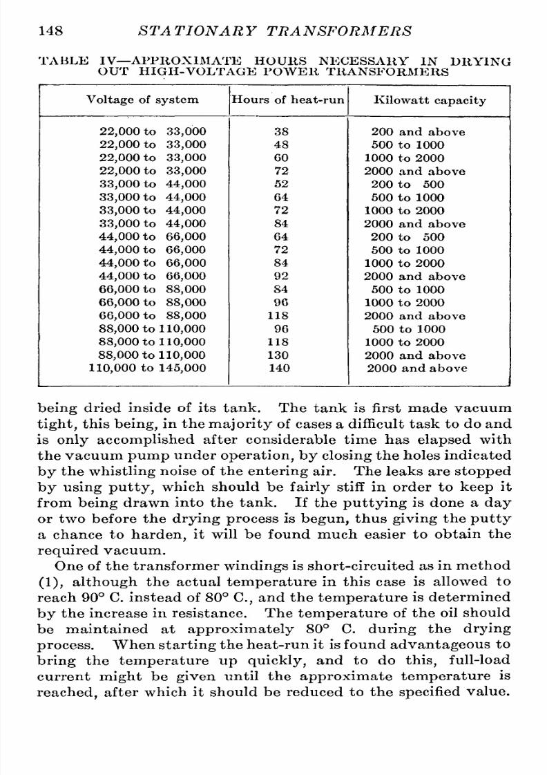
8/11/2019 Transformer Practice 1000194704
http://slidepdf.com/reader/full/transformer-practice-1000194704 160/290
148
STATIONARY
TRANSFORMERS
TABLE
IV
APPROXIMATE
HOURS NECESSARY
IN
DRYING
OUT
HIGH-
VOLTAGE
POWER
TRANSFORMERS
being
dried
inside
of
its
tank. The
tank
is
first
made
vacuum
tight,
his
being,
in
the
majority
of
cases
a
difficulttask to
do
and
is
only
accomplished
after
considerable time has
elapsed
with
the
vacuum
pump
under
operation,
y
closing
the
holes
indicated
by
the
whistling
noise of
the
entering
air.
The
leaks
are
stopped
by
using
putty,
which
should be
fairly
stiff
in
order
to
keep
it
from
being
drawn into
the tank. If the
puttying
is
done
a
day
or
two
before the
drying
process
is
begun,
thus
giving
the
putty
a
chance
to
harden,
it
will
be
found much
easier
to
obtain
the
required
vacuum.
One
of
the
transformer
windings
is
short-circuited
as
in
method
(1),
although
the
actual
temperature
in this
case
is
allowed
to
reach 90
C.
instead of 80
C,
and
the
temperature
is determined
by
the increase
in
resistance.
The
temperature
of
the oil
should
be
maintained
at
approximately
80
C.
during
the
drying
process.
When
starting
the
heat-run it is
found
advantageous
to
bring
the
temperature
up
quickly,
and
to
do
this,
full-load
current
might
be
given
until
the
approximate
temperature
is
reached,
after
which
it
should
be reduced
to
the
specified
value.

8/11/2019 Transformer Practice 1000194704
http://slidepdf.com/reader/full/transformer-practice-1000194704 161/290
CONSTRUCTION
OF
LARGE
TRANSFORMERS 149
In
addition
to
heating
by
electric
current
a
certain
amount
of
heat
should
be
applied
under the
bottom of
the
base
of
the
transformer.
The
most
satisfactory
method
of
applying
heat
to
the
base
is
to
use
grid
resistances
supplied
with sufficient
current to
maintain
the
grids
at
full red heat. The
grids
should
be
distributed
under the
base
so as
to
make
the
heating fairly
general,
and
not
confined
to
one
portion
of
the
surface.
In
case
some
other
method of
heating
the
base
is
used,
extreme
care
should
be
taken
that the
supply
of
the
heat does
not
become
too
intense,
otherwise
the
oil
may
be
injured.
The
idea
of
supply-ng
heat
to
the
base
is
to
maintain uniform
temperature
of the
oil
throughout
the transformer
structure at
a
uniform
tem-erature
of
80
C. It
is found that the
temperature
of
the
windings
reaches
90 C.
considerably
in advance
of
the
oil's
reach-ng
80
C; and,
for
this
reason,
it is
necessary
either
to
disconnect
the current
occasionally
or
to
reduce
it
to
a
small
percentage
of
full-load
current.
The
base
heating
should be
relied
on
to
maintain
the
oil
at
a
temperature
of 80
C.
as
long
as
it
will,
which
may
be
almost
constantly,
provided
a
sufficient
quantity
of
heat
is
applied.
These
specified
limits
of
hours
referred
to
above
are
for
the
actual
time
the
process
must
be
carried
on
after
the
oil
has reached
a
temperature
of 80
C. and
after
a
vacuum
of
20 in.
has been
established,
nd
does
not
refer
to
the
time
necessary
to
reach the 80 C.
point
and
20
in.
of
vacuum.
When
electric
current
is
not
available,
team at
a
low
pressure
may
be
used
for
heating,
the
steam
being
admitted
through
the
cooling
coil.
Also,
steam
may
be used
for
the base
heating;
in
which
case
the
entire
bottom
surface of the
base
should
be
sub-ected
to
the
heat
of
the
steam.
Care
should
be taken
in
ad-itting
steam
through
the
cooling
coils
that
the
temperature
of
the
oil
does
not
exceed
the Hmit. This
method
of
applying
heat
at
the
base
is
not
recommended, principally
because the steam
condenses
on
all
parts
of
the
transformer
tank.
(3)
This
method
of
drying
transformers
requires
the circulation
of
heated
air
through
the transformer
coils
and
core
while it is
in the
tank.
The
source
of
heated
air
should
be connected
to
the
base
valve
and the
top
cover
of
tank be
partly
removed.
The
temperature
of
the
air
inside
of
the tank
should
be
maintained
at
approximately
80
C,
and the
process
should
be
carried
on
under
this
temperature
for
a
period
of
three
days
for
units
of
moderate
size,
the
same
discretion
being
used
as
mentioned in

8/11/2019 Transformer Practice 1000194704
http://slidepdf.com/reader/full/transformer-practice-1000194704 162/290
150
STATIONARY
TRANSFORMERS
methods
(1)
and
(2).
The
temperature
of
the
heated air
as
it
enters
the
transformer should
not
exceed
100
C.
This
method
of
drying
transformers
is
especially
adapted
to
localities
where
no
electric
current
is
available.
The
oil
may
be
dried
by
the
vacuum
method
mentioned
in
(2),
or
by blowing
heated
air
through it,
referred
to
in
the
above
method. Where
the
vacuum
method
is
used,
the tank
must
be
filled
to
within
a
few
inches
of the
top,
so
that
the
cover
may
be
kept
sufficientlyarm
to
prevent
condensation
of
moisture.
In
case
the
transformer
tank
without
its
transformer
is
used
for
this
purpose,
it is
sometimes
necessary
to
put temporary
bracing
inside of
the
tank
to
prevent
collapsing
under
vacuum;
this
does
not
refer
to
the tank
of
cylinder
form.
A
12-hour
run
under
a
temperature
of 80 C.
with
not
less
than
20
in.
of
vacuum
should be
quite
sufficient
to
dry
transformer
oil.
All
large
installations
are
provided
with
tanks
for
this
purpose,
the
tanks
being
of
the
cylinder
form.
The
necessary
heat for
bringing
the
temperature
of the
oil
up
to
80 C.
may
be
obtained
by placing
a
steam
coil
or
an
electric
heater in
the bottom
of the tank.
Assuming
that
the
tank
in
which
the
oil is
being
dried,
will
radiate
approximately
0.25
watts
per
square
inch,
the
amount
of
electric
energy
required
to
maintain the
oil
at
the
specified
temperature
may
quite
easily
be
estimated.
The
electric
heater should be
about
double
the
size estimated
for the
purpose
of
shortening
the
time
neces-ary
to
reach the
desired
temperature.
Whether
a
steam
coil
or
an
electric
heater
is
used
it
must
be
placed
directly
on
the
bottom
of
the tank
as
it
is
necessary
to
maintain
the
oil
temperature
about
uniform
throughout.
In
case
steam
is
used,
its
pressure
should
not
be
greater
than
10
lb.
per
square
inch.
The
same
tank
may
be used for
drying
oil
by
means
of forced
circulation
of
air.
In
this
case
it is
necessary
to
run
the
piping
from the valve
in
the base of transformer
up
above the
oil
level,
and then down
to
the
air
pump,
the
top
of
the tank
having
an
adjustable
opening
for
permitting
the
air
to
circulate.
The
oil
must
be heated
to
a
temperature
of
approximately
100
C,
and
the
process
continued
until
the
oil
becomes
dry
as
deter-ined
by
test.
Comparison
of
Shell
and
Core
-type
Transformers. Trans-ormers
of
any
type
should
not
be
selected
at
random but
only

8/11/2019 Transformer Practice 1000194704
http://slidepdf.com/reader/full/transformer-practice-1000194704 163/290
CONISTRUCTION
OF
LARGE
TRANSFORMERS
151
after
careful
investigation
f
design,reliability
nd
simplicity
to
repair.
In
general
the
shell
type
transformer
is
a
difficult
piece
of
apparatus
to
repair
in
case
of
a
break-down;
the
difficulty
n-reases
in
almost
direct
proportion
with
increase
in
capacity,
and
in
the
larger
sizes it
becomes
advisable
to
send
for
a
trans-ormer
man
from the
factory
to
do
repairs.
This
disadvantage
has
been and
is
to-day
considered
the
only
cause
of
a
large
number
of
power
companies
operating
their lines
at
high
volt-ges
choosing
the
core-type
transformer.
Experienced
transmission
engineers
never
fail
to
realize
the
severe
conditions
to
which
transformers
are
subjected
to
in
practice,
nd whenever
they
ask manufacturers for
transformers
to
connect
to
their
high-voltage
lines,
eldom
fail
to
go
thoroughly
into the factor of
insulation,
hich,
to
them,
means
continuity
and
uninterrupted
service.
It
is
well-known that
the
insulation
of
a
high-voltage
transformer
is
subject
to
very
severe
potential
strains,
ome
of
which,
are:
(a)
Sudden
increase
in
generator
voltage.
(b)
Sudden
increase
in line
voltage
from
local
causes.
(c)
Direct
and indirect
lightning
discharges.
(d)
Ground
on
one
of
the
lines
depending
on
the
connection.
(e)
Internal
or
external
arcing
grounds.
(f)
Line
surges,
etc.
Reliable
data
taken
from
a
number of power
companies
oper-ting
long-distance
high-voltage
transmission
lines,
show,
that
the
shell-type
transformer
has been
more
reliable
than the
core
type
for
high-voltage
service.
With
such
large
sizes
as
there
are
operating
to-day,
this
class
of
apparatus
can
very
well
be
considered
as
one
of the
most
important,
if
not
the most
important
piece
of
apparatus
con-ected
to
a
transmission
system,
and
its
reliability
o
satis-actorily
operate
for
long
periods
of
time,
after
it
has
once
been
put
into
service,
is
looked
on
with
much
interest
and wonder
from
every
side.
To
think,
as
some
do,
that
once a
transformer
has been
put
into
successful
operation
it
will continue
to
operate
indefinitely
in
a
satisfactory
manner
without
any
attention is
a
wrong
idea.
It
requires
attention,
and
must
be
given
atten-ion
or
else it will
not
give
good
service.
Late
modifications
in
the
grading
of
insulation
on
the
end
turns
of
the
core-type
transformer
has
given
it
a
better
stand-

8/11/2019 Transformer Practice 1000194704
http://slidepdf.com/reader/full/transformer-practice-1000194704 164/290
152
ST
A
TIONA
R
Y
TRA
NSFORMERS
ing,
and
itis
now
considered
to
give
better service
and
can
be
de-ended
upon
in
this
regard
equally
as
well
as
the
shell-type
transformer.
Some of
the
most
important
advantages
and
disadvantages
of
these
two
general
types
might
be
summed
up
as
follows:
Advantages
in
Favor
of
the
Shell-type.
Greater
radiating
surface
of coils
and
core
resulting
in
a
lower
temperature
in
all
parts
of transformer.
This
point
has
an
important
bearing
on
the
insulation;
the
life
of
the
transformer
depending
on
the
strength
of the
insulation
of
the
hottest
part.
Interlacing
of coils
resulting
in lower
reactance
voltages,
hence
closer
regulation.
Mechanically
stronger
and better
able
to
withstand
the
electro-agnetic
stresses.
As
the
electro-magnetic
stresses
are
pro-ortional
to
the
square
of the
current,
a
short-circuit
of
many
times
the normal
full-load
current
will
produce
abnormal
strain
in the transformer.
Satisfactory
series-parallel
peration.
This
often
being
neces-ary
on
large
transmission
systems.
Advantages
in
Favor
of
the Core
Type.
^Easier
to
repair.
Disadvantages
of
the Shell
Type.
Difficult
to
remove a
coil.
Disadvantages
of
the Core
Type.
^With
low-voltage
winding
designed
for
22,000
volts and
above,
the
amount
of
insulation
next to
the
core means
a
larger
mean
turn
of
winding;
the
tem-erature
and P R loss
being
increased
thereby.
Radiating
surface
on
the
low-voltage
winding
very
poor,
resulting
in
higher
temperatures.
It
is
a
disadvantage
if,
say,
90
per
cent,
of the
transformer
operates
at
a
temperature
of
50 C. and the
remaining
10
per
cent, at
80
C.
as
this
point
is
tihe
weakest
link
in
the
insulation.
The
arrangement
of
coils
(concentric)
results
in
poorer
regula-ion
and
higher
reactance
voltages.
Less
mechanical
bracing
because of
its
design
and form.
Not
possible
to
operate
a
three-phase (delta-delta)
trans-ormer
in
case one
winding
becomes
damaged.
It
is
obviously
true
that
equally
good
results
can
be
obtained
with either
the
core-type
or
shell-type
construction,
but the de-ign
of
one or
the
other
would
depart
from the
regular
standard
expressed
above
if
equal performances
and
reliability
f
opera-ion
for
equal
conditions
of
load,
etc.,
are
desired.
The
differ-nce
is
slight
but
nevertheless
in
favor
of
the
shell-type
con-

8/11/2019 Transformer Practice 1000194704
http://slidepdf.com/reader/full/transformer-practice-1000194704 165/290
CONSTRUCTION
OF
LARGE
TRANSFORMERS
153
struction,articularly
rom the
operating
point
of
view,
with
the
exception
of
repairs,
should
a
break-down
occur.
The
shell-type
transformer
is
cheaper
than the
core-type
with
dear
copper space
(large
copper space
factor and
ordinary
iron)
And
likewise,
the
core-type
transformer
is
cheaper
than the
shell-
type
with
relatively
cheap
copper
space
(low
copper
space
factor
and
alloyed iron).
In
other
words,
shell-
and
core-type
transformers
cost
as
nearly
as
possible
equal
amounts
when
equal
volumes
of
copper
and
iron
spaces
are
equally
expensive.
Operation
of
Transformers.
The
general
idea is
that
trans-ormers
do
not
require
any
care or
attention
but that
they
will
operate
quitesatisfactorily
fter
having
been
put
in service
and
no
further
attention
is
necessary.
This
is,
however,
not
the
way
to
get
good
results,
although
in
some
fortunate
cases
it
might
apply
and has
applied.
Many
losses
of
large
power
transformers have
been
recorded
resulting
from the
cessation
of
the
coolingmedium,
all
of
which
could
have been
saved
if
proper
care
had
been
given
to
them.
Hourly
temperature
reading
is
the best
indication
of
any-hing
wrong
in this direction. As
is
well
known,
high-voltage
transformers
designed
to
operate
with
some
form
of
cooling
medium
cannot
run
continuously,
even
at
no
load,
without
the
cooling
medium,
since
the
iron
loss alone
cannot
be
taken
care
of
by
natural
cooling.
In
case
the
circulation
has been
stopped
by
any cause,
the
transformer
may
be
operated
until
the
coils
at
the
top
of
transformer
in
the
case
of
an
air-blast,
r
until
the
oil
in
case
of
a
water-cooled
transformer,
reaches
an
actual
temper-ture
of
80
C.
This
temperature
limit
under
ordinary
condi-ions
will
permit
the
transformer
to
continue
delivering
power
for
about
three
hours;
a
very
close watch
must
be
kept
of
the
temperature
and the
transformer
must
be
taken
out
of
service
as
soon as
it
reaches
this limit.
The
efficiency
f
a
transformer
is
usually
considered
to
be
its
most
important
feature
by
the
majority
of
central station
engineers
and
managers
operating
distribution
systems.
By
transmission
engineers
this factor is
not
considered
to
be the
most
important,
the
most
important
being
the
insulation and
mechanical
strength
of the
transformer,
and
consequently
its
reliability.
The
efficiency
s
no
doubt
an
important
feature
and
should
not
be
neglected
in the choice of
a
transformer
but
it
cannot
be
considered
as
the
most
important
feature
of
a
large

8/11/2019 Transformer Practice 1000194704
http://slidepdf.com/reader/full/transformer-practice-1000194704 166/290
154
STATIONARY TRANSFORMERS
high-voltage
power
trunsforiucr.
The
writer believes
the
right
order
of
importance
to
be:
1.
Reliability,
r
ability
to
supply
continuous
and
uninter-upted
service.
2.
Safety,
or
a
condition
conforming
with
safety
to
life
and
property.
3.
Efficiency,
r
a
condition
met with
after
proper
allowance
has been made
to
conform
with
1
and
2.
Reliability
s
referred
to
here
means
many
things
both
inter-al
and
external.
It
might
be
stated,
but
not
generally,
that
efficiency
s
the
principalpoint
in
discussing
transformers
from
their
operating point
of
view.
Where
large
high-voltage
power
transformers
are
concerned,
efficiency
an
be
said
to
take the
third
place
of
importance,
and
probably
second
place
where
low-voltagecity
distribution
transformers
are
concerned.
Excepting
cases
of
lightning
and
roasting
of
coils
due
to
constant
overload,
the
low-voltage
transformer
(as
used for
citylighting
and
motor
service)
is
free from
harm.
Not
so
with
the
large
high-voltage
power
transformers such
as we are
using
at
the
present day
in
connection
with
long-distance
transmis-ion
systems.
Causes of
failure
are
numerous;
that
is
to
say,
causes
that would and
sometimes
do
bring
about
burn-outs
of
coils,
moving
of both
coils
and
iron,
and
complete
failure
of
a
transformer.
Use and Value of Reactance.
A
transformer
may be
absolutely
reliable
electrically
ut
be weak
mechanically
which
might
bring
about
its
wreck.
We
know the
short-circuit
stresses
are
inverselyproportional
to
the
leakage
reactance
of the
transformer,
therefore
on
large
systems
of
large
power
the
use
of
high
reactance
or,
more
correctly,
high
automatic
reactance,
is
required
that
will
vary
with
the current. Several
interesting
ethods
are
from
time
to
time
suggested
and
some
of them
experimented
upon,
but,
to
keep
the
current
down
to
even
15
times
normal
current
on a
dead
short-circuit
and
brace
the
transformer
to
take
care
of
such
a
shock
and be
certain
that the
transformer is
quite
strong
enough
to
take
care
of other
severe
mechanical
stresses
we
need
more
experience.
Some
of the
methods
tried
and
in
their
experimental
stage,
are :
(a)
Use
of
reactance,
internal
or
external,
or
both.
(6)
Use of
resistance in
the
neutral of
grounded
systems.

8/11/2019 Transformer Practice 1000194704
http://slidepdf.com/reader/full/transformer-practice-1000194704 167/290

8/11/2019 Transformer Practice 1000194704
http://slidepdf.com/reader/full/transformer-practice-1000194704 168/290
156
STATIONARY TRANSFORMERS
will
be
equal
to
the
full-load
current
divided
by
the
percentage
reactance,
or:
/
577
/ =
1^
=
0029
=20,000
amperes
(18)
which
represents
an
amount
in
excess
of
30
times
normal full-
load
current.
If
(/)
is the force in
grams
produced
between
primary
and
secondary
windings,
and
(/)
the distance between
their
magnetic
centers,
the
mechanical
work done
in
moving
one
set
of
coils
through
the distance
(l)
against
the force
(/)
would
be:
^=/.^i.X
10^
joules
(19)
At
short-circuit
very
little
magnetic
flux
passes
through
the
secondary
coils
of
a
transformer,
but
if
the
system
is
sufficiently
large
to
maintain
constant
voltage
at
the
terminals
of
the
transformer
during
a period
of
short-circuit,
ull
magnetic
flux
passes
through
the
primary
coils.
Such
a
condition
can
never
exist sufficient
to
maintain
a
constant
voltage
at
the
terminals
of
transformers
located
at
the end of
long-distance
transmission
lines,
but
for
comparatively
short
distances
and
on
systems
of
practically
nlimited
power
behind the
transformers
(sufficient
to
roast
them)
and of close
regulation,
it is
possible
to
get
results that will do
so
much
damage
as
to
wreck
them
entirely.
Thus
a
transformer
with
a
2.9 per cent,
reactance
would
give
a
short-circuit
current at constant
voltage
of
30
times
full-load
current,
and
one
with
a
reactance
of
2.3
per
cent,
would
give
40
times
full-load
current,
while
one
with
4
per
cent,
reactance
would
produce
only
a
short-circuit
current
of
25 times.
This,
then, certainly
demonstrates that
more
reactance
in
the
trans-ormer
circuit
for better
protection
is
required,
and
that
the
reactance
should be
designed
proportional
to
the
current
so as
to
be
effective.
The
terminal
voltage
at
the transformer
during
short-circuit
is taken
from
the
leakage
inductance
of
the
transformer,
there-ore
:
810
E
1
0.706
E
r.
,
^
g.c.m.=
jr-j
mch
lb,
(20)
is
the force exerted
on
the transformer coils and
represents
the
work
done
in
moving
the
secondary
coils until their
magnetic

8/11/2019 Transformer Practice 1000194704
http://slidepdf.com/reader/full/transformer-practice-1000194704 169/290
CONSTRUCTION
OF
LARGE
TRANSFORMERS
157
centers
coincide
with
those
of the
primary
coils
(an
impossible
condition)
which
would
cause
zero
reactance
flux
to
pass
between
primary
and
secondary
coils.
Now
assuming
that
the
transformer
in
question
has
three
primary
coils
between
four
secondary
coils,
and the
distance
between the
magnetic
centers
of
the
adjacent
coils,
r
half-coils,
is
three
inches.
The force
exerted
on
such
a
transformer
and
its
respective
oils
would
be
something
like:
=
940,000
lb.
=426 tons.
This
force
is
exerted between the six
faces of
the
three
primary
coils
and the
corresponding
faces of the
secondary
coils,
and
on
every
coil
face
is
exerted the
force
of:
^
426
^,
,
-^=
-
=71
tons
6 6
If the
distance
between
adjacent
coils
had been
1.7 inches
the
force
exerted
on
the
transformers would have
been
1,750,000
lb,,
and
if
the
distance
had
been
4.3
inches
instead
of
three
inches,
the
force exerted
on
the
transformer would
have
been
under
400
tons,
or
about
65
tons
for
each
coil;
this is the
average
force,
which varies
between
0
and
130
tons.
In
the
design
of such
a
reactance
coil
the
following
formula
is
used
:
4.44
/ i6A^
E
Jos
0)
in which
(/)
is
the
frequency,
(A^)
the
number
of
turns,
((f))
he
flux
enclosed
by
the
conductor.
The
flux
produced by
a
coil
without
an
iron
core
being:
9
=
~j^
(21)
where
{N)
is
the
number of
turns,
{d)
the
inside
diameter,
(A)
a
constant
which
equals
0.28+0.125
(jA
and
/
the
current
in
the
coil.
The
tendency
of
leakage
flux
is
not
uniform
throughout
the
width
of the
coil
of
a
transformer,
but
is
greater
at
the
center
of
1
(I)
is the
length
and
D
the
mean
diameter
of
the
solenoid.

8/11/2019 Transformer Practice 1000194704
http://slidepdf.com/reader/full/transformer-practice-1000194704 170/290
158
STATIONARY TRANSFORMERS
the
coil
(if
the
coil
be
imbedded
in
iron).
If, then,
a
short-
circuit
should
occur,
the
coil
will
have
a
tendency
to
buckle,
and
should
it
not
be
sufficiently
trong
to
overcome
this
tendency,
and
its
equilibrium
be
disturbed,
the forces
of
conductor
upon
conductor
will
not
lie in
the
same
plane,
and
hence
are
liable
to
break the
insulation
tape
bindings,
and
heap
up
on
each other
at
the
point
of
most
intense
density.
The
shell-type
transformer
coils
have the
tendency
to
twist
at
their
outer
corners,
and the
vertical
portions
of the
coils
to
form
into
cable.
The
core-type
transformer
coils
have
the
tendency
to
be
forced
upward
or
downward
into the
iron
core
(the
heaviest
current coils
being,
in
most
instances,
forced
out
of
position).
If,
however,
the
centers
of the
primary
and
secondary
are
exactly
coincident
the
entire
force would
be
exerted
in
a
horizontal
direction,
and there would
be
no
tendency
for
any
of
the
coils
to
move
vertically.
Whether
the
primary
or
secondary
is
forced
up
depends
upon
which coil
has
its
center
line
above the
center
line
of the
other.
It
is
only recently
that
the
power-limiting
capabilities
of
reactance
have
come
to
the
fore.
This
has
largely
been
due
to
the
marked
movement
toward consolidation
and
concentration
in
the
central
station
industry
resulting
in unified
systems
of
gigantic
proportions,
the
loads
upon
which
may
fluctuate
suddenly
through
a
wide
range
or,
still
worse,
short-circuits
on
such
high
powered systems
may
give
rise
to
rushes
of
current
the volume
of
which
was
hitherto unknown
in
previous
systems.
In the last
few
years
we
have
come
to
larger
and
larger
systems,
and
consequently
greater
difficulties of
operation.
The
con-entration
of
power
for
economical
reasons
in
these
huge
power
plants,
the
dependence
for
vast
industrial
enterprises
and for
our
ever
increasingtransportation
systems,
as
well
as
for
lighting
and
industrial
power
from
ten,
twenty
or
thrity
substations
distributed
over
vast
areas
and
supplying
large
cities,
ake
it
absolutely
essential
that
they
shall l^e
protected
against
disturb-nce,
and that
every
possible
precaution
should be
taken,
which
experience
or
ingenuity
can
provide,
against
irregularity
n
opera-ion,
because
if
these
huge
transformer
systems
are
going
to
be
subjected
to
disturbance
and
interruption
of
service
other
factors
affecting
their
regulation
and
efficiency
ust
be
sacrificed
to
gain
this
end,
if
need
be.

8/11/2019 Transformer Practice 1000194704
http://slidepdf.com/reader/full/transformer-practice-1000194704 171/290
CONSTRUCTION
OF
LARGE
TRANSFORMERS
159
The
advantages
of
iron
and
air
reactance
coils
in
a
power
station
are
many,
provided
the
former
type
is
worked
at
a
suf-iciently
low
magnetic
density
so
that it
will
not
become
satur-ted
at
the
maximum
peak
of
a
short-circuit
current,
and
pro-ided
the
latter
type
has
not too
strong
an
external
magnetic
leakage,
and that both
types
are
used
only
when
needed.
They
are
effective in
protecting
ransformers
against
surges,
lightning,
and
short-circuits.
At
11
0,000
volts
and
over
a
phenomenon
makes
itself
felt,
speci-lly
in
large
transformers,
which
is
negligible
t
lower
voltages;
the
distributed
capacity
of
the
high-voltage
transformer
winding.
At
lower
voltages,
the transformer
capacity
(c)
is
negligible,
and the transformer
thus
is
an
inductive
apparatus,
and
as
such
is
free
from
all
high-frequency
disturbances,
such
as
traveling
waves,
impulses,
stationary
oscillations,
tc.
High-frequency
currents
cannot enter
the
transformer,
but
produce
high
voltage
between the
end
turns,
protection
against
which is
given by
the
high
insulation
of the end
turns
of
the
transformer,
and also
the
external
or
internal choke
coil. At
very
high
voltage
the
electrostatic
capacity
of
the
transformer
becomes
appreciable,
and the
high-potential
oils
of
the transformer
then
represent
a
circuit
containing
distributed
capacity, inductance,
resistance
and
conductance.
In
the
high-voltage
winding
of
a
transformer
the
inductance is
high
in
value
and
the
capacity
low,
that
is,
comparatively
speaking
lower than the
respective
constants
in
a
high-voltage
transmission
line.
The
result,
in
general,
is
that
the
oscillations
are
higher
in
voltage
and lower
in
current,
in the
former.
The
danger
to
which
a
transformer
is
exposed
by
high-
frequency
disturbances
from
the
line
side,
is
not
limited
to
the
end
turns
only,
but
damage
may
be done
anywhere
inside
of
the
transformer.
A choke
coil
or
reactance
between
the
transmission line
and
transformer
might
or
might
not
in this
case
become
a source
of
danger.
It
protects
the
transformer
from
certain line disturb-nces
but
does
not
protect
the
transformer
itself
from disturb-nces
which
originate
nside its
windings;
in
fact the
addition
of
this
choke
coil has the
tendency
to
throw
back the
disturbance
and
thereby
increase
the
internal
voltage
and
destructiveness.
Recently
it
has
become
customary
to
specify
that
transformers
of
large
sizes
and
high
voltages
must
not
have less
than
ap-roximatel
5
per
cent,
reactance for
the
protection
of
trans-

8/11/2019 Transformer Practice 1000194704
http://slidepdf.com/reader/full/transformer-practice-1000194704 172/290
160
STATIONARY
TRANSFORMERS
formers,
switches,
generators
and
all
parts
of
the
system against
the
high
mechanical
stresses
due
to
excessive
currents.
To
increase
the
reactance
of
a
given
transformer
one
or
several
modifications
are
possible,
s,
for instance:
(1)
Decreasing
the
dimensions
of
the
windings
in the
direction
in
which
the
leakage
flux
passes
through
the
wire-space.
(2)
Decreasing
the
number
of
groups
of
intermixed
primary
and
secondary
coils,
the
number
of
turns
of
each
group
being
correspondingly
reduced.
(3)
Increasing
the
total
number
of
turns
in
primary
and
secondary.
(4)
Increasing
the
length
of
turns
in
primary
and
secondary.
From
the
viewpoint
of
safety
to
the
transformer
itself
by
the
introduction
of
higher
reactance
within
the
transformer,
little
practical
benefit is
derived.
No
hard
and
fast
rule
can
be
given
for the
correct
location
of
reactance.
There
are
several
reasons
against
making
it
all
a
part
of the
transformer.
Of
course,
so
far
as
the
generating
stations
are
concerned
inductive
reactance
in
any
form in
connection
with
high
systems
is
important,
but
where
trans-ormers
are
located
at
the
end
of
long
transmission
lines
it
may
or
may
not
be
necessary
to
use
it.
To
make
a
large
transformer
of
large
power
with
high
reactance
is
not
an
easy
matter,
as
the
general principles
of
design
and
the economic utilization
of
materials obtain for
us
only
low
factors,
and
in
order
to
make
a
transformer
of
high
reactance
we
have
to
increase
its
cost
and
its
ampere
turns,
with
of
course
more
copper
and
more
winding
space,
and
consequently
a
larger
core
and
a
bigger
transformer
for
the
same
output.
If
it is
desired
to
increase
the
reactance
by
increasing
the
space
between
the
primary
and
secondary
windings,
the
same
results
are
obtained
and
the
efficiency
of
the transformer
is
reduced.
Placing
reactance
in
the transformer
itself
is
very
effective
on
short-circuit,
hereas
an
external
current-limiting
eactance
will
not
generally
be
so
effective
because
it
is
not
on
general
principles
designed
for the
short-
circuit
current
and its
value
consequently
is
about
frustrated
by
magnetic
saturation.
A
reactance
is
required
only
during
the
short-circuit.
In
that
case,
why
then
should
an
expensive
and
inefficient
transformer
be
considered
when
a
short-circuit
might
occur
only
once
in five
years;
would it
not
be
much
better
to
arrange
a
reactance
external
so
that its
maximum
flux
on

8/11/2019 Transformer Practice 1000194704
http://slidepdf.com/reader/full/transformer-practice-1000194704 173/290
CONSTRUCTION
OF
LARGE
TRANSFORMERS
161
short-circuit
is
about
equal
to
its
voltage
flux?
If
a
reactance
is
put
in
to
limit the short-circuit
current,
the
reactance must
be
there
when the
short-circuit
occurs.
All
long
transmission
lines
possess
magnetic
reactance
which tend
to
reduce the
volt-ge
so
that less
reactance
will
be
required
for
similar
trans-ormers
located at
the
end of the
line
than
those
at
the
generating
station.
Earthing
the
Neutral of Transformers.
The
chief
advantage
of resistance in the
neutral
of
a
star-connected
system
is
to
limit
the earth
current
on
short-circuit.
To arrive
at
a
close
value
of
resistance
that
will limit
the earth
current
at
all
times
is
not
easy,
in
fact
in
most
cases
impossible;
he
ideal condition
being
where the load
and
voltage
of the
system
are
not
disturbed.
The
two extreme
conditions
of
operation
are
the
insulated
system
and
solid-grounded
ystem.
Of
these
two,
experienceso
far has
proved
the better
to
be the
grounded
system,
and whether
we
ground through
resistance
or
dead
ground
the
method
depends
entirely
n
the
system
itself.
Both
methods
will
work
satis-actory
while
certain conditions
of
operation
exist
and
likewise
both
will
vary
under
one
particular
ondition,
it
being
better
or
worse
in
one or
the other
depending
on
the
kind
of
disturbance.
It
seems
to
appear
that the best
way
to
limit
the
current
and
disconnect
the
circuit
at
the
same
time,
in
preference
to
ground-ng
through
resistance,
ould
be
to
add
automatic resistance
in
the line side which
would
come
into
effect
when the
line
current
reached
a
given
value and
actuate
the
oil
switches. A
broken
insulator
or
ground
of
any
kind
on
the
line,
develops
a
short-circuit
which
will
interrupt
the
service
depending
on
the
exactness
of
the resistance
in
the
grounded
circuit
and
neutral;
generally
speaking
the
service
is
interrupted
whether
there
be
resistance in
the
grounded
neutral
or
not.
It
is
often
stated
that
with
one
line
down
and
grounded
in
an
insulated
delta
system
(a
non-grounded
delta
system),
an
interruption
r
short-circuit
will
not
occur.
This
statement
is
very vague
and
might
lead
those who have
not
had
experience
with
very
high-
voltage
system
(voltages
above
60,000
volts)
to
believe
that
in
the
majority
of
cases
it is
correct.
It
may
be
stated that it is
not
correct
for
neither
the
non-grounded
star
or
delta
systems operate
at
these
high voltages
except
in
very
unusual
cases.
The
primary
or
secondary
may
be
put
to
earth
or
ground through
a
group
of star-connected
transformers
as
shown
in
Fig.
122,
or,
11

8/11/2019 Transformer Practice 1000194704
http://slidepdf.com/reader/full/transformer-practice-1000194704 174/290
162 ST
A
TIONA
R Y
TRA NSFORMERS
if
these transformers
are
not
available
and
a
ground
connection
must
be
used,
a
substitute
might
be
made
similar
to
Fig.
123.
With
this
connection
grounded
as
shown,
the
maximum insulation
strain between
any
of
its
secondary
or
primary
windings
respec-ively
to
ground
(whichever
side
might
be
grounded)
will be
87
per
cent,
of
full
voltage
between
terminals,
but
with
the
trans-ormer
method of
grounding
and
under
the
same
operating con-itions
the
maximum
strain
will
not
be
greater
than
58
per
cent,
of
full
voltage
between
terminals.
Grounding
the neutral
point
Fig.
122.
Method
of
grounding
an
insulated
delta
system
through
induc-ance
coils.
of the
high-voltage
windings
of
transformers
connected
to
a
transmission
line will
immediately
operate
the
relays
or
circuit-
breakers
should
one
of the
line
conductors
fall
to
the
ground.
Grounding
the
neutral
point
of the
secondary,
or
low-voltage
windings,
will
not
operate
the
relays
unless
some
special
provision
has been
made,
and
even
so,
before the
relays
or
circuit-breakers
are
actually
operated
the
secondary
or
low-
voltage
windings
are
made
subject
to
very
high-voltage
stresses.
The best method of
all
is
to
ground
the neutral
points
of
both the
high-
and
low-voltage
windings
necessary,
and where
delta-delta
systems
are
used,
ground
the
windings
as
shown
in
Fig.
123.
A
common
condition
found
in
practice
is
the
non-grounded
delta-delta
system.
On
systems
where the
ground
connection
is
used,
the
character of the
ground

8/11/2019 Transformer Practice 1000194704
http://slidepdf.com/reader/full/transformer-practice-1000194704 175/290

8/11/2019 Transformer Practice 1000194704
http://slidepdf.com/reader/full/transformer-practice-1000194704 176/290
164
STATIONARY
TRANSFORMERS
An
ordinary
pipe resting
on
the
ground
was
found to
give
an
average
of
2000
ohms.
The
same
pipe
driven
6
feet
into
the
ground
gave
15
ohms,
and the
same
pipe
resting
on
dry
pebble
gave
several
thousands
of
ohms.
As
the
pipe
penetrates
the
earth,
it is
found that
each addi-ional
foot
adds
a
conductance about
proportional
o
the added
length.
The
specific
esistance
of
the earth
will
depend
upon
what
chemicals exist
around the
metal
plate
and how much
moisture
there
is
present.
In
a
dry
sand-bank
the
resistance is
prac-ically
infinite.
In
a
salt marsh the
specific
resistance
is
extremely
low,
being
about
one
ohm.
Resistances
of earth
connections
will
vary
greatly
even
in
the
same
locality.
The
engineer
is
interested
mostly
in
the earth
connection in
the
immediate
vicinity
of the earth
pipe
or
plate;
because
in
the
main
body
of the
earth,
the
area
of
cross-section
through
which
there
is
current,
is
so
enormously great
that
even
if
the
specific
resistance is
very
high
the total
resistance
becomes
negligibly
small.
If the earth
plate
should lie
in
the
dry
non-onducting
stratum
of the
top
layer,
it
is advisable
to
get
some means
of
introducing
better
conductivity,
not
only
in
the
contact
between the
plate
and
the
earth,
but
also
between
the
earth
conducting
layer
deeper
down.
The
best
means
of
accomplishing
this is
to
pour
a
salt
solution
around the
iron
pipe
and allow
it
to
percolate
down
to
a
good conducting
stratum.
In
order that
this solution
may
not
be
washed
out
by
the
natural
filtration
of
rain
water,
it is
well
to
leave
a
considerable
quantity
of
crystal
salt around the
pipe
at
the
surface,
so
that
rain
water
flowing
through
will dissolve
the
salt and
carry
it
continuously
to
the
lower
strata.
Salt has the
additional
value
of
holding
moisture.
Objections
have from
time
to
time
been made
to
the
use
of
salt
in
stating
that
it
would
be
destructive
to
the
metal
of the
pipe.
Under
the
usual
conditions it is
found that the
chemical
action
on an
iron
pipe
is of
negligible
value.
Iron
pipe
is
very
cheap,
and it would be better
practice
to
use
the
salt,
even
if
it
did
destroy
the
pipe
within
a
period
of
years
which
it
does
not.
If
it is desired
to
decrease
the
resistance
of earth
connections,
it is
necessary
to
drive
earth
pipes
that
are
separatedby
a
distance
sufficient
to
keep
one
out
of the dense
field of
current
of
the

8/11/2019 Transformer Practice 1000194704
http://slidepdf.com/reader/full/transformer-practice-1000194704 177/290
CONSTRUCTION
OF
LARGE
TRANSFORMERS
165
other.
The
current
density
in
the
earth
around
a
pipe-earth
drops
off
approximately
as
the
square
of the
distance.
A
good
method
is
to
drive
multiple
pipes
at
least
6
ft.
apart
and
con-ect
them
together,
and the
resistance
will
decrease almost
in
proportion
to
the
number of
pipes.
The
more
salt
water
placed
around
a
pipe-earth,
he
less
the
potential
gradient
near
the
pipe. Inversely
the
drier
the
earth,
the
more
the concentration
of
potential
ear
the
pipe.
Earth
pipes
have
a
certain maximum
critical
value of
current
which
they
will
carry
continuously
without
drying
out.
The
application
of
a
high
voltage
might
have
so
bad
an
effect that
the earth
around
a
pipe
will
be
dried
quickly
and the
earth-
plate
lose
its effectiveness
as a
ground.
As the
moisture is
boiled
out
and
evaporated
at
the
surface of the
pipe,
the
sur-ounding
moisture in
the
earth
is
being supplied,
but
the
vapor
generated
tends
to
drive
away
this moisture
from the
pipe.
The
diameter
of the
pipe
effects the
resistance
comparatively
little.
Doubling
the
diameter
of
a
pipe
decreases the
resistance
by
a
small
percentage.
Switching.
In
laying
out
systems
which
must
of
necessity
be
more or
less
complicated,
the
question
of
continuity
of
service
should
be
always kept
in mind
and
placed
first
in
importance.
At the
present
time
there
are
in
operation
many
intricate
systems
with tie-lines
between
receiving
stations
and
generating
sta-ions.
This
arrangement
presents
difficulty
n
providing
pro-ection
on
account
of
the
interconnections
and
disturbance
in
any
one
line
may
cause
an
interruption
of
a
large
portion
of the
system.
Systems
are
sometimes
overrelayed,
relays
which
the
oper-tor
cannot
thoroughly
understand
being
installed.
The result
is
that he
oftentimes
renders
some
of them
inoperative
by
plugging
with
wood
to
prevent
what
he
considers
unnecessary
interruptions
of
service,
which
may
be
at
the
expense
of needed
protection
to
the
transformers.
Before
deciding
upon
the
system
of
connections
a
careful
study
should
be
made
to
deter-ine
the
simplest
possible
arrangement,
when
taking
into
account
not
only
the
delivery
f
energy
under
normal
conditions,
but also
continuity
of service under
abnormal conditions.
Low-voltage
moderate
capacity
transformer
switching
is
simple.
High-voltage
power
transformers
connected
to
large
systems
are
not
quite
so
simple
in their
arrangement
of
switching
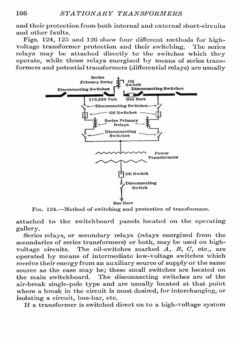
8/11/2019 Transformer Practice 1000194704
http://slidepdf.com/reader/full/transformer-practice-1000194704 178/290
166
ST
A
TIONA
R Y
TRA NSFORMERS
and
their
protection
rom both internal
and
external
short-circuits
and other
faults.
Figs.
124,
125
and
120
show four
different
methods
for
high-
voltage
transformer
protection
and
their
switching.
The
series
relays
may
be
attached
directly
to
the
switches
which
thoy
operate,
while
those
relays
energized
by
means
of series
trans-ormers
and
potential
ransformers
(differential
elays)
are
usually
Series
Primary
Eelay
Disconnecting
Switches
lelay
SI
OH
Switch
hes
r^
Dteco:
on
Switch
Dteconnecttog
Swltcihes
110,000
Volt
Bus
Bars
-Disconnecting
Switches
*];
on
Switches
.
Series
Primary
Relays
~~
Disconnecting
Switches
[o]
n
Switch
Power
Transformers
6.
Disconnecting
/
Switch
Bus
Bars
Fig. 124.
Method
of
switching
and
protection
of
transformers.
attached
to
the switchboard
panels
located
on
the
operating
gallery.
Series
relays,
or
secondary
relays
(relays
energized
from
the
secondaries
of
series
transformers)
or
both,
may
be
used
on
high-
voltage
circuits.
The
oil-switches marked
A, B, C,
etc.,
are
operated
by
means
of intermediate
low-voltage
switches which
receive their
energy
from
an
auxiliary
ource
of
supply
or
the
same
source as
the
case
may
be;
these
small
switches
are
located
on
the main switchboard.
The
disconnecting
switches
are
of
the
air-break
single-pole
type
and
are
usually
located
at
that
point
where
a
break
in
the
circuit
is
most
desired,
for
interchanging,
r
isolating
circuit,
us-bar,
etc.
If
a
transformer
isswitched
direct
on
to
a
high-voltage
system

8/11/2019 Transformer Practice 1000194704
http://slidepdf.com/reader/full/transformer-practice-1000194704 179/290
CONSTRUCTION
OF
LARGE
TRANSFORMERS
167
there
may
be
a
rush
of
current
equivalent
in
its
suddenness
to
what
usually
occurs
in
high-frequency
experiments,
and
the
exact
amount
of
the
rush will
depend
largely
on
the
local
capacity
of
the
high-voltage
switches
and
their
connections,
that
is,
the
distance
they
are
located
from
the
transformers
to
which
they
are
connected.
The
usual
shocks
to
the
end
turns
of
transformers
due
to
switching
are
dependent
upon
the
load,
character of the
load,
Disconnecting
Switch
110,000
Volt
o
Disconnecting
Switch
Oil
Switch
Inverse
tlme-
Umlt
series
Relay
for
A Switch
Series
Transformer
Tlme-llinlt
over-load
Relay
for
C
Switch
|6|
Disconnecting
^t
Switch
(/
on
Switch
Series
Transformer
Power
Trans^formers
yr
I
Keverse c
:p-'^||forA*H
Series
Transformer
Reverse
cnrrent
Relay
Switches
I
Disconnecting
Switch
f
To
Low
Voltage
Bus
Bars
t
Fig.
125.
Two
methods
of
switching
and
protecting
transformers.
type
of switch
(oil
type
or
air,
and
single-
r multi-break),
the
time
allowed
for
opening,
and
the
method
of
switching.
As
regards
the
switching
itself,
here
are
several
ways
in which
transformers
can
be
switched
on
to
a
line,
as
for
example:
(1)
Switching
in
the
transformers
on
an
open
line.
(2)
Switching
non
-energized
transformers
on an energized
line.
(3)
Switching
energized
line
on
to
energizied
transformers.
(4)
Switching
in
the
transformers and
afterward
raising
the
voltage
at
generating
station.
(5)
Switching
under
any
of
the
above conditions
but
with
resistance
or
reactance
in
series.

8/11/2019 Transformer Practice 1000194704
http://slidepdf.com/reader/full/transformer-practice-1000194704 180/290
168
STATIONARY TRANSFORMERS
(0)
Switching on
the
low-voltage
side
of
transformers.
(7)
Switching
on
the
high-voltage
side
of
transformers.
(8)
Switching energized
transformers
on
long
transmission
lines
with
transformers
already
switched in
at
the
receiving
station,
but dead.
(9)
Switching
in
transformers
during lightning
storms,
line
disturbances,
etc.
(10)
Switching
in
transformers
using
oil-switches.
(11)
Switching
in
transformers
using
air-break
switches.
Series
Transformer
Disconnecting
Switcli
Disconnecting
Vh\
Switch
-^[pjoil
witch
Bus
Bars
o^Si
Disconnecting'
Switch
Definite
Time
limit
Relay
for
A
D
Switches
Inverse
Tlme-
lijiiit
Relay
for
B
E
Switches
Non-automatic
Oil Switch
Series
Transformer
Disconnecting
Switch
Oil Switch
Disconnecting
Switch
Generator
Busses
Fig.
126.
Another
method
of
transformer
switching
and
protection.
Most of the methods above shown
are
bad and
may
lead
to
excessive
surges
being
thrown
on
the
windings
of the
trans-ormers.
Next
to
(4),
the best
method
is
to
do
all
switching
on
the
low-voltage
side
whenever
possible using only
3-pole
oil-switches
in
the
case
of
three-phase
circuits.
The
method
(4)
is
generally
not
possible
because
of the
necessity
of
lowering

8/11/2019 Transformer Practice 1000194704
http://slidepdf.com/reader/full/transformer-practice-1000194704 181/290
CONSTRUCTION OF
LARGE TRANSFORMERS 169
the
voltage
of the
system.
The
next
preferential
method
is
where
a
receiving
station
is
dead
and
has
to
be
energized
all
high-voltage
switches
being
closed
first.
A
very
important
point
about
switching
is
the
time-limit.
If it
is
necessary
to
open
a
circuit
instantaneously
on
very
large loads,
switching
can
be
made
large
enough
to
do the
work,
but where
economy
of
design
is
required,
a
time-limit
should
be
used,
and, probably,
a
reactance to
limit the flow
of
current.
The
time-limit
with
its
relay
will
therefore
take
care
of that
amount
of
current
which it is
set
for
and will
permit
the
switch
to
open
up
to
the
load under
which
it is
able
to
operate
safely.
If
a
reactance
is
used
in
connection
with switches
of
this
kind,
it
might
be well
to
provide
for
some
arrangement
whereby
it
can
be
brought
into
use
only
when
it is
needed
or,
for
instance,
when
the
circuit is
actually
being
opened.
Aside
from
the above
methods
of
closing
circuits,
there
are
two
conditions of
opening
circuits which
should
be
avoided,
as:
(1) Opening
a
long
transmission
line
under
heavy
load, on
the
high-voltage
side.
(2)
Opening
a
long
transmission line
on
the
high-voltage
side
with
no-load.
Method
(1)
refers
principally
to
short-circuits,
and method
(2)
to
a high-voltage
line
required
to
be
made
dead.
If
a
live circuit is
to
be
cut out at
all
it should
be done
from the
low-
voltage
side
no
matter
what the
load
conditions
are.
High-voltage
switches
for
large
power
transformers should
be of
the
most
substantial
mechanical construction
and
capable
of
safely
breaking
a
circuit
under
extreme
conditions.
For
comparatively
small
installations it is still
customary
to
use
expulsion
fuse-switches
installed
inside of
a
delta
connection,
that
is,
one on
each
lead
or
6
for
a three-phase
group.
This
is
not
good
practice
for the
reason
that
with
a
blown-out
fuse
(leaving
the delta
open)
a
bad
phase
distortion
may
occur.
Where
connections of
this kind
are
necessary,
they
should
be
made
through
air-break
switches
and
not
fused
switches.

8/11/2019 Transformer Practice 1000194704
http://slidepdf.com/reader/full/transformer-practice-1000194704 182/290
CHAPTER
X
AUTO
TRANSFORMERS
The
ordinary
auto-transformer
is
a
transformer
having
but
one
winding.
The
primary voltage
is
usually
applied
across
the
total
winding,
or
in
other
words,
across
the total
number
of
turns,
and
the
secondary
circuit is
connected between
two
taps
taken
off from
the
same winding,
the
voltage
ratio
being
equal
to
the
ratio
of
numbers
of
turns.
The auto-transformer shown
in
Fig.
127
has
two
taps
brought
out
at
a
and
h.
Thus
the
whole
or
part
of
the
winding
vasiy
be
Fig. 127.
Step-up
auto-transformer.
used
to
raise
the
voltage
or
lower the
voltage
simply
by
changing
the
connections.
For
example,
the
primary
a
b,
is
wound
for
1000
volts,
a
c
and b d each
being
wound for 50 volts. As
will
be
seen,
by
taking
a
tap
out
from
a
and
d,
the
secondary
gives
1000-1-50
=
1050
volts. And
by
moving
to
the far
end of
the
winding,
a,
the
voltage maybe
raised from
1050-1-50
=
1100
volts. In
order
to
obtain 550
volts all that
is
necessary
is
to
bring
two
leads
out
from
X
and
d,
or x
and
c;
the
secondary
then
gives
1050 500
=
550 volts.
170

8/11/2019 Transformer Practice 1000194704
http://slidepdf.com/reader/full/transformer-practice-1000194704 183/290

8/11/2019 Transformer Practice 1000194704
http://slidepdf.com/reader/full/transformer-practice-1000194704 184/290
172
STATIONARY
TRANSFORMERS
auto-transformer
required
for this service?
and what
will
be the
actual
power
delivered
over
the
line?
The actual
rating
of the
auto-transformer
will
be,
5000X750
=
3750
kilowatts.
The
total
power
delivered
to
the
line
will
be,
45,000
+
750
=
33,750
kilowatts.
In
Fig.
128
the
secondary voltage
is smaller
than
the
primary.
The
voltages,
b
d
and
c
a,
are
thus
subtracted
from
the
primary
to
form the
secondary
voltage
of
the
circuit.
The
auto-trans-ormer
may
thus
act
as a
step-up
or
step-down
transformer.
The action of
an
auto-transformer
is similar
to
that
of
the
ordinary
transformer,
the
essential difference
between the
two
lies
in
the fact
that
in
the
transformer the
primary
and
secondary
windings
are
separate
and
insulated
from each
other,
while
in
the
auto-transformer
a
portion
of
the
winding
is
common
to
both
-1000-
-100-
-1100-
FiG. 129.
Two-phase
auto-transformation.
primary
and
secondary.
The
primary
and
secondary
currents
in both
types
of transformers
are
in
the
opposite
direction
to
each
other,
and thus
in
an
auto-transformer
a
portion
of the
winding
carries
only
the
difference
between
the
primary
and
secondary
currents.
In the
foregoing explanation
of
auto-transformation
the
ordinary
transformer will
be used
instead
of
the auto-transformer.
Two-phase,
four-wire,
auto-transformation
as
shown
in
Fig.
129,
where
the
secondary
winding
is
made
to
assist
the
primary,
may
be
considered
as
two
ordinary single-phase
circuits.
The
ratio
of
transformation
in
this
case
is
10 to
1,
therefore
we
obtain
by
the
connection
as
shown,
a
secondary
voltage
of
1100.
By
reversing
the
secondary
connection
it
is
possible
for
us
to
get
1000 - 100
=
900
volts.

8/11/2019 Transformer Practice 1000194704
http://slidepdf.com/reader/full/transformer-practice-1000194704 185/290
AUTO
TRANSFORMERS
173
If
we
should take
one
end
of the
secondary
windhig
and
connect
it
as
shown
in
Fig.
130
we
would
obtain
50
per
cent,
of
the
primary
voltage
plus 100,
which
is the total
secondary
voltage.
Then
assuming
the
primary
and
secondary
to
have
a
four-wire,
hat
is
to
say,
two
independent
single-phase
ystems,
we
would have
a
a
Ob
d
Fig.
130.
Two-phase
four-wire
auto-transformation.
secondary voltage
of
500
plus
100= 600
volts.
The
points,
x
and
y,
are
taps
brought
out
from the
middle
points
of
the
windings.
Another
two-phase
auto-transformation
is
represented
in
Fig.
131. Both
primary
and
secondary
areconnected
to
a
three-wire
Fig.
131.
Two-phase
three-wire
auto-transformation.
system
from
which
we
obtain
a
secondary voltage
of 1100
between
a' h
and
h
c'
,
and 1550
volts
between a'
and
c',
or
1100X1.41
=
1550
volts.
A
very
interesting
ombination
giving
a
five-wire,
wo-phase
transformation is
shown
in
Fig.
132.
From this
arrangement
it
is
seen
that
quite
a
number
of
different
voltages
and
phase

8/11/2019 Transformer Practice 1000194704
http://slidepdf.com/reader/full/transformer-practice-1000194704 186/290
174
STATIONARY TRANSFORMERS
relations
can
be
obtained,
and
by
simply shifting
the
connection
at
X
we
increase and
decrease
the
resultant
voltages.
At
a
re
rf
and
c x
d the
respectivephases
that
constitute
the
four-phase
relation
have
been
changed
from
45
degrees
to
a
o'
6
-1000
-500
^-nmPi
-100-
-1100-
300-
f
^1000
600- k-500-
U
100
-1100-
-500-
FiG.
132.
Two-phase
five-wire
auto-tranformation.
slightly
higher
value,
the
voltage
increasing
in
proportion
to
the
increase
of
phase
difference.
The
three-phasearrangement
shown
in
Fig.
133
is
a
method
of
auto-transformation
by
which
we are
enabled
to
supply
approxi-
-IflOO-
immJ
liK^^mJ
-1000-
-1000
*
immJ
n^^'^'iij^
-100
-^00-
-1040
-1040-
-1040-
-100-
FiG.
133.
Three-phase
star auto-transformation.
mately
1040
volts
to
the
secondary mains, 1,
2
and
3,
from
a
1732-volt
primary
source
of
supply,
using
three
transformers
with
a
ratio
of
10
to
1,
or
=
1000
to
100
volts.
Between
points
ah,h
c,
a
c,
we
obtain
500
X\/3=
866 volts.

8/11/2019 Transformer Practice 1000194704
http://slidepdf.com/reader/full/transformer-practice-1000194704 187/290
AUTO
TRANSFORMERS 175
Between
points
1
2,
2
3,
and
1
3,
there
exists
approximately
500
+
100
X
\/3
=
1040
volts.
The
three-phase
delta
connection
shown
in
Fig. 134,
with
its
three
secondary
windings
left
open-circuited,
ay
be
used
where
-loco-
1000
*
^1000
M^^sinJwmsiSiSirisismsi^
a
l
b
c
-im-
| -ioo^
c a
-500
=H
-SCO
Fig.
134.
Three-phase
auto-transformation
with
secondaries
open
circuited.
a
three-phase
500-volt
motor
is installed.
The
secondary
wind-ngs,
if
required,
may
be used at
the
same
time
for
lighting
or
power.
To
obtain
a
100-volt
lighting
service it will
be
necessary
to
connect
the
secondary
windings
in
delta,
running
a
three-wire
distribution
to the
source
of
supply,
ah
c.
This
method
of
Fig.
135.
Three-phase
delta
auto-transformation.
connecting
transformers
is
often
found
useful
in
places
where
transformers
of
correct
ratio
are
not
obtainable.
The
combination
shown
in
Fig.
135
has
its
secondary
windings
connected
in
circuit with
the
primary windings.
Like
Fig.
133
a
tap
is
brought
out
from
the
middle
of
each
winding;
but
instead

8/11/2019 Transformer Practice 1000194704
http://slidepdf.com/reader/full/transformer-practice-1000194704 188/290
176
STATIONARY
TRANSFORMERS
of
leading
out to
the
secondary
distribution,
tis
connected
to
one
end of
the
secondary
winding
as
shown
at
1,
2
and
3;
the
result
of
which
represents
a
phase
displacement
as
shown
in
the
vector
diagram.
Fig.
136.
Three-phase
double-star
auto-traiisformation.
Using
the
same
transformers
as
in
the
previous
examples,
connecting
A
B
C
to
a
500X\/3=866
volt
supply,
it is
possible
for
us
to
obtain
a
number
of different
voltages
for
the
second-ry
distribution,
such
as
three
at
1000,
three
at
600,
three
-1732-
-1783
-1000-
-100-
^1732-
-1000-
-500 ^-
1000
\
-500V3-
B^
Fig.
137.
Three-phase
star auto-transformation
with
secondaries
open-
circuited.
at
520,
six
at
500,
three
at
173,
and three
at
100
volts,
re-pectively
(Fig.
136).
According
to
the
raito
of
transformation
applied
at
the
secondary
distribution
it is
understood
that
the
kilowatt
capacity
of
the
transformers
will
vary.
Another
three-phase
combination is
shown
in
Fig.
137,
where
it is
shown that the
primary
windings
are
connected in
star,
and

8/11/2019 Transformer Practice 1000194704
http://slidepdf.com/reader/full/transformer-practice-1000194704 189/290
AUTO TRANSFORMERS
177
the three
leads,
ABC,
are
connected
to
a
1732-volt
supply.
From
the
middle
of
each
primary
winding
a
tap
is
brought
out
at
a
6
and
c.
The
secondary
voltage
across
ab,
b
c
and
a
c
is
500X\/3
=866
volts.
The
100-volt
secondary
winding
may
be used for
power
-1350-
-1000-
Lm|Mi -[
-1850-
-1^-
-1000-
U^^^ioaoMm^^
-1000-
^100-
-500-
-500
^100-
-500-
FiG. 138.
Three-phase
auto-transformation
using
primary
windings
only.
and
lighting,
ingle
or
polyphase,
depending
upon
the
size
and
design
of
the
transformer.
Fig.
138
represents
a
three-phasetransformation,using only
the
primary windings.
One end of each
primary
winding
is
connected
to the
middle
point
of
another
primary
winding.
Three-phase,
1350
volts,
impressed
on
A
B C
will
give
500
volts
on
1-2, 2-3,
and 1-3.
12

8/11/2019 Transformer Practice 1000194704
http://slidepdf.com/reader/full/transformer-practice-1000194704 190/290
CHAPTER
XI
CONSTANT-CURRENT
TRANSFORMERS
AND
OPERATION
For
operating
arc-
and incandescent
lighting
systems
from
constant-potential, alternating-current
mains,
the
constant-
current
transformer
is
frequently
used. It
is
designed
to
take
a
nearly
constant
current
at
varying
angles
of
lag
from
constant-
potential circuits,
and
to
deliver
a
constant
current
from
its
secondary winding
to
a
receiving
circuit
of variable resistance.
Thus the transformer
operates
automatically
with
respect
to
the
load,
making
it
possible
to cut
out
any
number of
lamps,
from
full
rated
load
to
zero load,
while
still
maintaining
a
con-tant
current
on
the
line.
The
self-regulating
characteristic
is
obtained
by
constructing
the transformer
in
such
a
manner
that either the
primary
or
secondary
coil
is
balanced
through
a
system
of
levers
against
a counterweight,
which
permits
the
distance between
primary
and
secondary
coil
to
vary.
This
automatically
increases
or
decreases
the
reactance
of the
circuit
in
such
amount
as
to
hold
the
current constant
irrespective
of
the
load.
For the
majority
of
series incandescent
systems
the
constant-
current
transformer
will
be found lower
in
initial
cost
and
more
reliable
in
service
than the
reactive coil
method,
as
it combines
in
one
element the
advantages
of
a
regulating
device and
an
insulat-ng
transformer.
One
type
of
transformer consists of
a core
of the double
magnetic
type
with
three vertical limbs and
two
flat coils
enclosing
the
central limb.
The lower
coil,
which
is
fixed,
is
the
primary,
while the
upper
one,
or
secondary,
is
carried
on
a
balanced
suspension,
and
is
free
to
move
along
the
central
limb
of
the
core.
The
repulsion
between the
fixed and
moving
windings
of
the
system
for
a given
position
is
directly
proportional
to
the
current
in
the
windings.
For series
enclosed,
arc-lighting
on
alternating-current
circuits
the
constant-current
transformer
is
universally
used.
This
type
usually
consists
of
a
movable
secondary
and fixed
primary
wind-
178

8/11/2019 Transformer Practice 1000194704
http://slidepdf.com/reader/full/transformer-practice-1000194704 191/290

8/11/2019 Transformer Practice 1000194704
http://slidepdf.com/reader/full/transformer-practice-1000194704 192/290
180
STATIONARY
TRANSFORMERS
maries
are
separated.
When the
primaries
and secondaries
are
separated
by
the
maximum
distance,
the
effective force
tending
to
draw
them
together
should be
less than when
they
are
in
full-load
position;
that
is,
when
the
primaries
and
secondaries
are
close
together.
For
capacities
of
100
lamps,
or
less,
there
is
one
primary
and
one
secondary coil,
the
primary
being
stationary,
and the
secondary,
or
constant-current
coil is
suspended
and
so
balanced
by
weights
that the
repulsion
between
it
and the
primary
changes
the
distance
between
them
with variations
of
load,
the
current
in
the
secondary
being kept
constant.
For
capacities
of
100,
or
more,
there
are
two
primary
and
two
secondary
coils.
A
separate
circuit
of
lamps
may
be
operated
from
each
secondary,
the
two
circuits
being
operated
at
different
currents
if
desired.
The maximum
load of
each
circuit,
hen
operated
separately,
will
be one-half the
total
capacity
of
the
transformer.
However,
when
it is
necessary to
operate
the
two
circuits
at
unequal
loads,
the load
of
one
circuit
being
less,
and
of the other
greater,
than one-half the
rated
capacty
of the
transformer,
the
coils
may
be
connected
together
in
the
multi-circuit
arrangement,
which
will
allow loads
up
to
the total
capacity
of the
trans-ormer
to
be
carried
upon
one
circuit.
For
capacities
of
250,
or
more,
there
may
be
one
or
two
primary
and
two
secondary
coils,
wo
circuits
being operated
from each
secondary,
thus
giving
four
circuits
from the transformer. It
is
not
necessary
that
the loads
on
the
two
circuits
from
each
coil
be
balanced,and,
if
desired,
he total load
can
be
carried
on one
cir-uit
alone,
provided
the
insulation of
the
line is
such
as
to
admit
the
high
voltage
which will
be introduced.
Constant-current
transformers
are
of the air-
and
oil-cooled
type.
The
air-cooled
type
is
surrounded
by
a
corrugated
sheet
iron
or
cast-iron
casing
with
a
base and
top
of
cast
iron. The
oil-cooled
type
is
sur-ounded
by
a
cast-iron
case,
providing
ample
cooling
surface.
The
working
parts
are
immersed
in
oil,
hich assists
in
conduct-ng
away
the heat.
Constant-current
transformers
are
usually
located
in
stations
where
electric
energy
is
generated,
received
or
transformed,
as,
for
instance,
a
receiving
station
at
the
end of
a
long
high-voltage
line;
although
in
large
cities
they
are,
for
convenience,
located
in district sub-stations
and close
to
distribution
centers.

8/11/2019 Transformer Practice 1000194704
http://slidepdf.com/reader/full/transformer-practice-1000194704 193/290
CONSTANT-CURRENT
TRANSFORMERS 181
They
are
made
to
operate
on
60-
125-cycle
and
even
133-cycle
systems,
and
for
any
reasonable
primary
voltage.
It
is
cus-omary
to
furnish
a
60-
125-cycle
transformer
for
a
125-
133-cycle
system.
The
constant-current
transformer
will maintain
constant
current
even
more
accurately
than the
constant
potential
transformer
maintains
uniform
potential,
nd
its
regulation
ver
a
range
from
full-load
to
one-third
its
rated
capacity
will
come
within
1.5
per
cent,
if
properly adjusted.
The
efficiencies
of
constant-current
transformers
with
a
full
load of
arc
lamps
vary
at 60
cycles
from
about
96
per
cent,
for
the
100-lamp
transformer
to
about
94.5
per
cent,
for the
25-lamp
transformer.
Another
constant-current
transformer known
as
the
edge-ise
wound
type
is
fast
replacing
the
older
type
mentioned
above.
From this
modern
method
of
construction
several
advantages
are
derived,
principal
among
which is
the almost
absolute im-ossibil
of
an
internal
short-circuit,s
the
voltage
between
any
two
adjacent
conductors
consists
of
only
the
volts
per
turn
of the
transformer,
or
at
the
most about
10
volts.
The
construction
of
this
type
is
somewhat
different.
The
core
is
built
up
of
thin laminations
of sheet
steel and
has
a
center
leg
of
cruciform
shape.
This
form of
construction
not
only
tends
to
support
itself,hereby
requiring
a
very
thin
angle
for
securely
clamping
the
laminse
and
decreasing
the
eddy
current
in
the
clamp,
but the form of
construction
also
gives
the
most
economical
flux
path
as
well
as
permitting
a
smaller
diameter
coil.
The
primary
and
secondary
consist
of
four
concentric
edge-ise
wound
coils
of
double
cotton
covered
rectangular
wire.
The
four
sections
are
assembled
together
concentrically
ith wooden
spacing
strips
to
maintain
at
all
points
an
air-duct
of
sufficient
width.
Two surfaces
of each conductor
are
therefore
exposed
to
the
currents
of
air
passing
through
the
air-ducts,
thereby
in-reasin
the
effective
radiating
urface
of
each
coil
by
about
three-old.
The
large
radiating
surface
with
the
consequent
cool
run-ing
allows
a
very
high
current
density
which
permits
of
less
copper
per
ampere-turn,
less
weight,
less floor
space,
and,
of
course,
a
cheaper
transformer
for
the
same
kilowatt
rating
than
the
older
type
above
mentioned.

8/11/2019 Transformer Practice 1000194704
http://slidepdf.com/reader/full/transformer-practice-1000194704 194/290
182
STATIONARY TRANSFORMERS
Construction of
Transformer.
The
core
of
this efficient
and
most
modern
type
of
constant-current
transformer
is built
up
of
laminations
of
specially
nnealed
iron,
which
are
sheared
to
the
required
length
and
width.
Each sheet
or
lamina) is
treated
by
coating
the surfaces
with
a
species
of
japan,
which
serves
to
I'educe
materially
he
eddy
current
loss
in
the
core.
This
japan
is
applied
by
passing
each
individual
sheet between rolls
which
are
constantly
kept
moist
with
the
japan.
After
passing
the
rolls,
the
pieces
of
iron
are
carried
along
a
travelling
table,
where
they
are
dried
by
passing
nozzles
through
which
air
is
blown.
Short-Circuit,
Flug
*
H
l-x-^^J
Fig.
140.
Connections
for
single,
or
multiple
of
series
arc or
incandescent
circuits.
Like
the
core-type
constant
potential
transformer
the
construc-ion
commences
with
the
iron,
the
iron
legs
being
assembled
in
a
horizontal
position.
After
all
the
laminations
have been
stacked
together
and
wrapped
with
the
necessary
sheets of
horn-fiber,
the whole
assembly
should
be
placed
in
a
press
under
considerable
pressure
which will
reduce the
weight
of
the
iron
to
the
required
dimensions.
In
the
factory
an
hydraulic
press
is
generally
used,
the
pressure
appliedbeing equivalent
to
several
tons;
the
temperature
is
also
increased
to
about
250
F.
There
are
three
legs
in
each
transformer
two
of
rectangular
shape,
and
one
of
cruciform
shape
which is
larger
in
cross-
section
than the
two
rectangularlegs
each
legbeing
assembled
and
handled
separately
until
completed,
after
which
the three
are
raised
vertically
nd
accurately spaced
for
the
placing
of
end
laminations.
After the
end
laminations
have
been
put
in
and
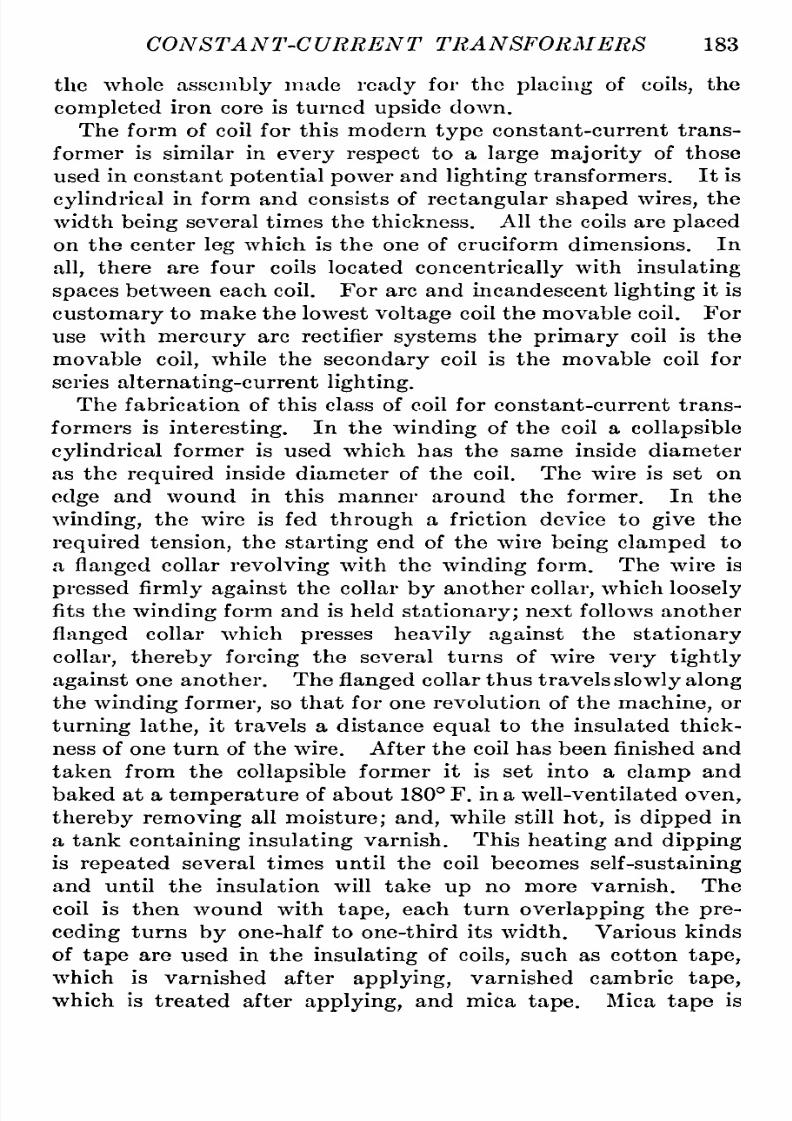
8/11/2019 Transformer Practice 1000194704
http://slidepdf.com/reader/full/transformer-practice-1000194704 195/290
CONSTANT-CURRENT
TRANSFORMERS 183
the
whole
assembly
made
ready
for
the
placuig
of
coils,
the
completed
iron
core
is
turned
upside
down.
The
form of
coil
for
this
modern
type
constant-current trans-ormer
is
similar in
every
respect
to
a
large
majority
of
those
used
in
constant
potential
power
and
lighting
transformers.
It
is
cylindrical
n
form and
consists
of
rectangularshaped
wires,
the
width
being
several
times
the
thickness.
All the
coils
are
placed
on
the
center
leg
which is the
one
of cruciform
dimensions.
In
all,
there
are
four
coils
located
concentrically
ith
insulating
spaces
between
each
coil.
For
arc
and
incandescent
lighting
t
is
customary
to
make the
lowest
voltage
coil
the movable
coil.
For
use
with
mercury
arc
rectifier
systems
the
primary
coil is
the
movable
coil,
while
the
secondary
coil is
the
movable coil
for
series
alternating-current
ighting.
The
fabrication
of
this
class
of
coil
for
constant-current
trans-ormers
is
interesting.
In the
winding
of
the
coil
a
collapsible
cylindrical
ormer
is
used
which
has the
same
inside diameter
as
the
required
inside diameter
of the
coil.
The wire is
set
on
edge
and
wound
in this
manner
around the
former.
In
the
winding,
the
wire
is
fed
through
a
friction device
to
give
the
required
tension,
the
starting
end of the
wire
being clamped
to
a
flanged
collar
revolving
with
the
winding
form.
The
wire is
pressedfirmly
against
the collar
by
another
collar,
which
loosely
fits
the
winding
form
and
is
held
stationary;
next
follows another
flanged
collar which
presses
heavily against
the
stationary
collar,
thereby
forcing
the several
turns
of
wire
very
tightly
against
one
another.
The
flanged
collar
thus
travels
slowlyalong
the
winding
former,
so
that
for
one
revolution
of the
machine,
or
turning
lathe,
it
travels
a
distance
equal
to
the
insulated thick-ess
of
one
turn
of the
wire.
After the
coil
has
been
finished
and
taken from the
collapsible
ormer
it is
set
into
a
clamp
and
baked
at
a
temperature
of
about
180
F. in
a
well-ventilated
oven,
thereby
removing
all
moisture;
and,
while still
hot,
is
dipped
in
a
tank
containinginsulating
varnish.
This
heating
and
dipping
is
repeated
several
times until
the
coil
becomes
self-sustaining
and
until
the
insulation
will
take
up
no
more
varnish.
The
coil
is
then wound
with
tape,
each
turn
overlapping
the
pre-eding
turns
by
one-half
to
one-third
its
width.
Various
kinds
of
tape
are
used in the
insulating
of
coils,
uch
as
cotton
tape,
which
is
varnished
after
applying,
varnished cambric
tape,
which
is
treated
after
applying,
and
mica
tape.
Mica
tape
is

8/11/2019 Transformer Practice 1000194704
http://slidepdf.com/reader/full/transformer-practice-1000194704 196/290
184
ST A
TIONA
R
Y
TRA
NSFORMERS
only
used
on
very
high-voltage
transformers.
Where
cotton
tape
is
employed
it receives
a
brushing
of the
best
quality
of
insulating
varnish,
is
then
baked,
revarnished
and
rebaked,
this
process
being
repeated
several
times
for
each
tape.
The
regulation
of
this
transformer
comes
within
one-tenth of
1
amp.
above
or
below
normal
current
from full-load
to
no-load.
Fig.
140
(A),
(B)
and
(C)
show three
different
methods of
connecting
the
secondaries
of
constant-current
transformers
for
single,
r
multiple
of
series
arc or
incandescent
circuits.
Method
C.T.
Tx
Fig.
141.
Method
of
operation
from
three-phase primaries, using
two
constant
current
transformers
in each
case.
(A)
represents
a
simple
circuit;
(B)
a
single
secondary
winding
with
two
circuits
operated
in series
or
singly
as
desired;
(C)
shows
a
multi-circuit
secondary,
each
circuit
being
operated
independently.
Fig.
141
(A)
and
(B)
represents
two
methods
of
operating
constant-current
transformers and
series-arc
lighting
from
three-phase
primaries.
The
secondaries
of
(A)
show
two
inde-endent
circuits,
each
circuit
being supplied
from
separate
transformers,
the
primaries
of
which
are
wound for
2000
volts
and
2000X\/3/2
volts
respectively.
The
secondaries
of
(B)
also
show
two
independent
secondary
circuits,
ach
being
in
two
parts
as
shown.
Before
shipment,
constant-current
transformers
are
made
subject
to
an
insulation
test
of
10,000
volts between
secondary,
primary
and
all
parts;
also
between
primary,
secondary
and
all

8/11/2019 Transformer Practice 1000194704
http://slidepdf.com/reader/full/transformer-practice-1000194704 197/290
CONSTANT-CURRENT TRANSFORMERS
185
parts.
The
duration of
the
insulation
test
is
one
minute.
If
however,
the
primary
voltage
is
above
5000,
which
is
very
rarely
the
case,
the
insulation
test
is
twice
normal
voltage.
The
modern
type
of
constant-current
transformer
referred
to
above,
has
a
guaranteed
temperature
rise
not
exceeding
55
C.
based
on
a
room
temperature
of
25
C.
If
the
temperature
of
the
room
is
greater
than
25
C,
0.5
per
cent,
for
each
degree'
difference
should
be added
to
the
observed
rise
of
temperature;
if
less,
subtracted.
The record
tests
of
a
100-lamp
6.6 amp.,
air-cooled
constant-
current
transformer
are
shown
below.
CONSTANT-CURRENT TRANSFORMER
RECORD
TEST
Full-load
=100
lamps
6.6
amp.
60
cycles
Test
Lights
connected
60
Core
loss
in
watts
Copper
loss
in
watts
Sec.
open-circuit
voltage
Pri.
current
at
2200
voltage
(Temperature
rise
after
12
hours'
run
55
C.)
Efficiency
in
per
cent,
at
full-load.
.
.
.
At
75
per
cent,
full-load
At 50
per
cent,
full-load
At
33
per
cent,
full-load
Power
factor
in
per
cent,
at
full-load
.
At
75
per
cent,
full-load
At
50
per
cent,
full-load
At 33
per
cent,
full-load
892
402
6930
18.7
98.5
94.1
91.4
70.2
53.2
36.4
When
operating
a
load
of
6
.
6
amp,
lamps plus
7
.
5
per
cent,
line
loss,
the
voltage
and
power
factor
at
the
lamp
are
:
Volts
per
lamp
4-
line
loss
=83
per
cent.
Power
factor
of
lamp
=
84
per
cent.

8/11/2019 Transformer Practice 1000194704
http://slidepdf.com/reader/full/transformer-practice-1000194704 198/290
CHAPTER
XII
SERIES
TRANSFORMERS AND
THEIR
OPERATION
The
characteristics
of the
series
transformer
are
not
very
generally
known.
It is
used in
connection with
alternating-
current
amnaeters
and
wattmeters
where
the
voltage
of
the
circuit is
so
high
as
to
render
it
unsafe
to
connect
the
instrument
directly
into the circuit
and when the
current to
be
measured
is
greater
than the
capacity
of
the
instrument,
and it
is
also used
in
connection
with
relays.
The series transformer
was
first
considered
and
used
in
con-ection
with
street
lighting
systems,
but
was an
entire
failure.
im
n
Sa -^*r-
Ip
^P
*
o
7^
Fig.
142.
Fig.
143.
Figs.
142
and
143.
^Fundamental
series
transformer
vector relations.
For almost
20
years
it
kept
in
the
background
until it
came
into
commercial
use
in
connection with
measuring
instruments.
At this
time its
accuracy
was
equal
to
any
other
instrument
on
the
market
and
as
the
accuracy
of
instruments
improved,
the
demand
for
a more
accurate
device increased.
Also with the
introduction of
higher
voltages
better insulation
was
required,
insulation
that
would
not
only
protect
the
instruments
but also
the
operator.
As
time
went
on
it
was
found
essential
to
use
a
magnetic
circuit
without
joints
in
order
to
keep
the
magnetizing
current
within reasonable limits
compared
with
the
accuracy
of
transformation.
To
accomplish
this
a core was
made of sheet-
iron
rings
the
primary
and
secondary
windings being
placed on
this
core.
For
high
voltages,
insulation
became
a
serious
problem.
The
number
of
turns
of
insulation
had
to
be
increased.
This
meant
a
considerable
waste
of time and
money,
and
even
after
they were
once
in
place
it
was
difficult
to
take
care
of the
heat
186

8/11/2019 Transformer Practice 1000194704
http://slidepdf.com/reader/full/transformer-practice-1000194704 199/290

8/11/2019 Transformer Practice 1000194704
http://slidepdf.com/reader/full/transformer-practice-1000194704 200/290
188
STATIONARY
TRANSFORMERS
it
only
means
such
a
decrease
in the
current
as
would
increase
the
resultingmagnetic
flux
and
secondary
e.m.f.
sufficiently
o
main-ain
the
current
through
the
increased
resistance.
Under
ordinary
conditions
the
resistance in
the
secondary
circuit is
low,
so
that the
secondary
e. m.
f. is
low
and also
the
resultant
mag-etic
flux.
If the
secondary
be
short-circuited
so
that
there
is
no
magnetic
leakage
between the
windings,
and
current
put
on
the
line,a
magnetic
flux
will
be
set
up
in
the
primary.
This
flux
produces
an
e.m.f. in the
secondary
which
sets
up
a
current
opposed
to
that
in
the
primary.
The
result
is
that
the flux
threading
the
windings
will
be reduced
to
a
value
which will
produce
a
sufficient
0
io
A
Fig.
144. Direction of
three-phase
currents
chosen
arbitrarily
or
con-enience.
voltage
to
establish
current
through
the
secondary
resistance.
Thus the
magnetomotive
force of the
primary
current
is less than
that of the
secondary
current,
by
an
amount
such that the flux
produced
thereby
generates
the
voltage
required
to
send the
secondary
current
through
the
resistance of
the
secondary
circuit,
he
vector
sum
of the
secondary
current and the
mag-etizing
current
being
equal
to
the
primary
current.
When
the
secondary
resistance
is
increased,
there
will
be
a
decrease
in
the
secondary
current
which
allows
a
larger
resultant
flux,
which in
turn
decreases
the
secondary e.m.f.,
which in-reases
the
secondary
current.
When
a
stable
condition is
reached there
is
a
greater
secondary
e.m
f. and
a
less
secondary
current.
In
order
to
determine
the
characteristics of
a
series
transformer
it
is in
general
necessary
to
know the
resistances
and
reactances
of the
primary
and
secondary
windings
of
the
transformer
and
of the external
secondary
circuit,
nd the
amount
and
power-factor
of the
exciting
current at
the
various
operating
flux
densities
in
the
transformer. If
no
magnetizing
current
were
required,
the
secondary
ampere-turns
would be
in

8/11/2019 Transformer Practice 1000194704
http://slidepdf.com/reader/full/transformer-practice-1000194704 201/290
SERIES
TRANSFORMERS
189
approximate
equilibrium
with
tlie
primary
ampere-turns
and
consequently
the
ratio
of the
primary
to
the
secondary
current
would be the
inverse
of the number
of
turns.
In order
to
attain
this
ratio
as nearly
as
possible
the
iron
is
worked
considerably
below
the
knee
of
the
B-H
curve,
so
that
very
little
magnetiz-ng
force
is
required.
The
series transformer is
worked
at
about
one-tenth
the
magnetic
density
of the shunt
transformer,
due
to
the fact that
a
large
cross-section
of
iron is
used. It
is
readily
understood
that
a
series
transformer
differs
very
much
mechanically
and
electrically
rom
a
shunt
transformer;
the latter
maintaining
a
practically
onstant
voltage
on
the
secondary irrespective
f the
load,
while
the former
must
change
its
secondary voltage
in order
to
change
its
secondary
current.
The
fundational
expression
for
the
current
of
a
series
trans-ormer
is
the
same as
for
a
constant
potential
transformer,
or
^
=
^
=
k
or
N
s
=
KN
V
(22)
I
s
N
p
^ ^ ^
where
I
p
=
primary
current.
I
s
=
secondary
current.
N
p
=
primary
turns
of
wire in
series.
A^
s
=
secondary
turns
in series.
K
=
constant
=
ratio of
transformation.
If the
ratio
of
transformation
is
known
and
primary
turns
fixed,
the
secondary
turns
are
equal
to
primary
turns
multiplied
by
the
ratio
of
transformation.
Assuming
a one
to
one
ratio
and
a
non-inductive
secondary
load,
the
diagram
shown
in
Fig.
142
is
obtained.
The
primary
current
and
e.m.f.
are
equal
and
opposite
in
phase
to
the
secondary
current
and
e.m.f.
and
as
the load
is non-inductive
the
primary
current
is in time
phase
with
the
primary voltage.
where
0 I
p
=
primary
current.
0
E
p
=
primary
e.m.f.
O I
s
=
secondary
current.
0
E
s
=
secondary
e.m.f.
and
0
I
m
=
magnetizing
current.
In
actual
operation
the
secondary
current
is
in time
phase
with
the
secondary
e.m.f.
if
the
secondary
load
is
non-inductive,
ut
the
primary
current
lags
behind
the
primary
e.m.f.,
as
shown
in
Fig.
143
by
the
angle
0.
The
secondary
ampere-turns
0 I
s,
and
the
primary
turns

8/11/2019 Transformer Practice 1000194704
http://slidepdf.com/reader/full/transformer-practice-1000194704 202/290
190
STATIONARY
TRANSFORMERS
0
I
p
being
equal
to
the
line
current
multiplied
by
the
primary
turns
is
made
up
of
two
components
/
p
and
/
p'-O
I
p'.
I
p'
being
that
part
which
supplies
the
core
loss,
and 0
I
p'
that
part
which is
equal
and
opposite
to
the
secondary
ampere-turns.
The
iron
loss
and
wattless
components
ase
I
p'
I
p
and
/
p.
In
a
well
designed
series
transformer,
the
secondary
ampere-
turns
for
non-inductive
secondary
load
can
be taken
as
equal
to
0 /
p-l p'
I
p ,
there fore
secondary
amperes
is
To
determine
this,
it
is
merely
necessary
to
find the
ampere-
turns
0
I
p
supplying
the
iron
loss,
subtract
this
value
from
the
primary
ampere-turns
/
p
and I
p'
,
and
divide
by
the
secondary
turns
/
s.
To
determine
the
iron
loss
it is
necessary
to
know
the loss
in
watts
per
unit
weight
of
iron
at
a
given
frequency
and
varying
induction.
Let
P
represent
the
watts
loss
at
a
given
frequency
and
induction,
the
iron
loss
current,
N
s
secondary
turns,
then
p
Iron
loss
current
=
^
(24)
and
P
N
s
ampere-
turns
(iron
loss)
=1 N
s
=
^^
(25)
secondary
ampere-turns
=
1
p
N
p
p
(26)
E
and
N
p
P
secondary
amperes
=
/
Pj^-
p
(27)
1
s
If
the ratio
of
transformation is
made
equal
to
-^
the
second-
^
1
p
P
ary
current
will
be
less
than
the
desired
value
by
the
amount
^
amperes.
The
error
in
the
transformation
is
As
PXlOO
....
per
cent,
error
of
rj =i
-^
(28;
^
I
p
I
sXi^
To
compensate
for
this
error
the
secondary
turns
must
be
slightly
I
p
diminished
from
the
ratio
j^
N
s
so
that the
secondary
current
will
equal
Is.

8/11/2019 Transformer Practice 1000194704
http://slidepdf.com/reader/full/transformer-practice-1000194704 203/290
SERIES TRANSFORMERS 191
Assume
that the
secondary
is
on
short-circuit,
nd
for
con-enience,
that
there
is
no
magnetic
leakage
between
primary
and
secondary.
At the
moment
the
current
is
started,
flux
is
set
up
in
the
primary
winding.
This flux
produces
an
e.m.f.
in the
secondary
which
sets
up
a
current
opposed
to that
in
the
primary.
The result
is
that
the
flux
threading
the two
windings
will
be reduced
to
a
value
producing
only
sufficient
voltage
to
cause
current
through
the
secondary
resistance,
thus
restoring
approximate
equilibrium
between the
primary
and
secondary
currents.
Thus the
magnetomotive
force
of
Fig.
145.
Method
of
obtaining
equal
three-phase
current
readingsby
the
use
of
two-
or
three-series
transformers.
the
primary
current
is
less
than
that
of the
secondary
current
by
an
amount
such
that
the flux
produced
generates
the
voltage
required
to
send the
secondary
current
through
the
resistance
the
vector
sum
of
this
current
and the
magnetizing
current
being
equal
to
the
primary
current.
A
series
transformer
should
maintain
a
practically
onstant
ratio
between
its
primary
and
secondary
through
its full
range
of
load.
Such
a
condition
can
only
be
approached
but
not
absolutely
reached,
since
the
magnetizing
current
becomes
a

8/11/2019 Transformer Practice 1000194704
http://slidepdf.com/reader/full/transformer-practice-1000194704 204/290
192
STATIONARY
TRANSFORMERS
formidable factor
in
preventing
a
constant
ratio.
A
minimum
magnetizing
current
is
accomplished
in
commercial
transformers
by
having
an
abundance
of
iron in
the
core,
thus
working
the
iron
at
a
very
low
magnetic
density,
permitting
the
current
ratio
of the
primary
to
the
secondary
to
vary
approximately
in inverse
ratio
to
the
number
of
turns.
As iron is
worked
considerably
below the
knee
of
the
B-H.
curve,
a
good
range
of load
is
allowed
for
ammeters,
wattmeters
and
relays
to
be
operated
on
the
secondary.
In
either
a
delta-
or
star-connected
three-phase system
the
currents
in
the
three
leads
are
displaced
120
degrees
from
each
other and
one
of
the
leads
may
be
considered
a
common
return
for
the other
two.
Assuming
the
instantaneous
direction
of
current
in
leads A
and
C
to
follow the
arrows
shown
in
Fig.
144,
then
the
direction
of
the
current
in
B
will
follow
the
arrow
in
the
opposite
direction. With
a
delta-connected
system
the
current
in
lead
A
is
the resultant of
that
in
the
two
phases
B
A
and C A
;
the
current
in
lead B
is the
resultant of
that in
the
two
phases
A B
and
C
B;
and
the
current
in
C is
the
resultant
of
that
in
A C and B
C.
With
the
star
connection,
the direction
of the
two
currents
A
and
C
are
in
opposite
directions
to
the
neutral
point,
and the
current
B
toward the
neutral
point
0.
If
all the
secondaries
of
series
transformer
are
not
arranged
in
the
same
direction,
it
will
be found
that the
phase
relation
between the three
phases
will be either
60
or
120
degrees.
In
either
a
delta-
or
star-connected
group
of
transformers it
becomes
necessary
to
reverse
the
secondary
leads
with
respect
to
the
others
when
a
change
of
phase
relation
is desired.
A
connection
com-rising
two
series
transformers
is
shown
in
Fig.
145
where A and
C
are
connected
to two
ammeters,
and
the
opposite
end of
second-ry
winding
connected
to
a
common
wire
at
0.
In
the
vector
diagram
it is
shown
that
0
A
is
equal
to
the
current
in lead
A
both
in
magnitude
and
direction
and
0 C
the
current
in
lead
C
which
has
a
phase
relation
oi
120
degrees.
The
resultant
current
that
is
in
the
common
wire O
is
equal
in
magnitude
and
direction
to
0
B'.
The
ammeter
(2)
indicates
the
current
in
lead
B,
and its
reading
is
equal
to
the
value
shown
in
Fig.
145.
Assume that
one
of the
transformers
is reversed
as
at
C
,
Fig.
146.
Referring
to
the vector
diagram,
0 A
represents
the
current
in
lead A
both
in
value
and
direction,
0
C
the
current
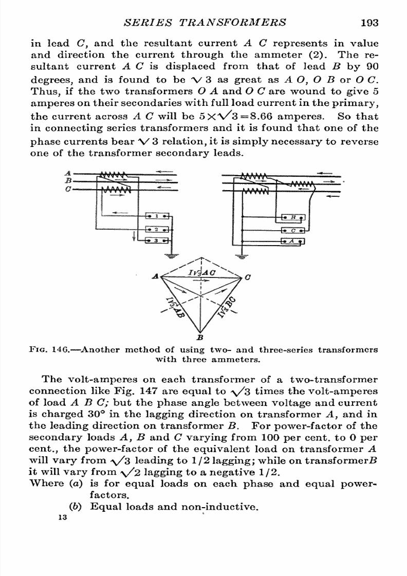
8/11/2019 Transformer Practice 1000194704
http://slidepdf.com/reader/full/transformer-practice-1000194704 205/290
SERIES
TRANSFORMERS 193
in lead
C,
and
the resultant
current
A
C
represents
in
value
and
direction the
current
through
the
ammeter
(2).
The
re-ultant
current
A
C
is
displaced
from
that
of
lead
B
by
90
degrees,
and
is
found
to
be V3
as
great
sls
A
0,
0
B
or
0
C.
Thus,
if
the
two
transformers
0 A and 0
C
are
wound
to
give
5
amperes
on
their
secondaries with
full load
current
in the
primary,
the
current
across
A C
will
be
5X'\/3=8,66
amperes.
So that
in
connecting
series
transformers and it
is
found that
one
of the
phase
currents
bear
V
3
relation,
t is
simply
necessary
to
reverse
one
of
the transformer
secondary
leads.
Fig.
146.
^Another
method of
using
two- and
three-series
transformers
with
three
ammeters.
The
volt-amperes
on
each
transformer
of
a
two-transformer
connection like
Fig.
147
are
equal
to
\/s
times
the
volt-amperes
of
load
A B
C;
but
the
phase angle
between
voltage
and
current
is
charged
30
in
the
lagging
direction
on
transformer
A,
and
in
the
leading
direction
on
transformer
B.
For
power-factor
of
the
secondary
loads
A,
B
and
C
varying
from
100
per
cent,
to
0
per
cent,,
the
power-factor
of the
equivalent
load
on
transformer
A
will
vary
from
y/s
leading
to
1/2
lagging;
while
on
transformer^
it will
vary
from
\/2
lagging
to
a
negative 1/2.
Where
(a)
is
for
equal
loads
on
each
phase
and
equal
power-
factors.
(6) Equal
loads and
non-inductive.
13

8/11/2019 Transformer Practice 1000194704
http://slidepdf.com/reader/full/transformer-practice-1000194704 206/290
194
STATIONARY
TRANSFORMERS
(c)
Equal
loads
(loads
A
and
B
non-inductive)
and
C
50
per
cent,
power-factor.
(d)
Equal
loads
(loads
A
and
B
non-inductive)
C
10
per
cent,
power-factor.
A
tendency
with
laggingpower-factor
in
load
C
is
to
increase
the
equivalent
load
on
the
transformer
A
which
is
connected
to
the
leading
phase,
and
to
diminish
the
equivalent
load
on
trans-ormer
B
which
is
connected in
the
lagging
phase.
Low
power-
factor
on
both
A
and B
combined with
high
power-factor
in
C
produces
similar
results.
There
are a
number
of
different
ways
of
connecting
two
or
Fig.
147.
Varying
phase
relations due
to
varying
loads and
power
factors
through
the
series
transformers.
more
series
transformers
to
a
polyphase
system.
One
or
more
may
be used
in connection with
alternating-current
relays
for
operating
circuits for
overload,
reverse
power,
reverse
phase,
and
low
voltage.
Some
of
the
connections
for
this
purpose
are
shown
in
Figs.
148
to
149.
One
series
transformer
is
sufficient
for
opening
the
circuit
of
a
single-phase
system,
and
at
the
same
time
is
used
in
connection
with
an
ammeter
and
wattmeter
as
shown
in
Fig.
148.
For
three-
phase
working,
one,
two
or
three series
transformers
may
be
used
for
relays,
ammeters
and
wattmeters.
It is
often
recom-ended
that
three
series
transformers
should
be
used
for
three-

8/11/2019 Transformer Practice 1000194704
http://slidepdf.com/reader/full/transformer-practice-1000194704 207/290

8/11/2019 Transformer Practice 1000194704
http://slidepdf.com/reader/full/transformer-practice-1000194704 208/290
196
STATIONARY
TRANSFORMERS
In
connection
with overload
relays
one
series
transformer
may
be
used
for
operating
a
three-phase
system,
and when
operating
three-phase
wattmeters,
two
are
all that
is
'required.
The
connection
shown
in
Fig.
150
will
be
found
to
give
good
results,
s
each
transformer
has
its
own
tripping
arrangement.
Three transformers
are
quite
common
operating
together
on a
three-phase,
star-connected
system,
neutral
point
grounded
or
ungrounded.
If
all
the
secondary
windings
are
not
arranged
in
the
same
direction
the
phase
relations
between
one
outside
wire
and
the
-400-
UlAAflJLr
iL
-400-
Lr-rrH-
J
a
-400-
nnnnnn
eooo-
-6000-
6000-
FiG.
150.
Method
of
connecting
two
series transformers
and
relays
to
a
three-phase
system.
middle
wire,
and the
middle
and the
other
outside wire
will
be
60
degrees
instead
of
120
degrees.
In order
to
obtain
a
phase
relation
of 120
degrees
between
each
winding,
one
of
the
second-ry
windings
must
be
reversed.
Fig.
151
represents
three
series
transformers with
all the
secondary
windings
connected
in
one
direction.
It
makes
no
difference
whether the
method
of
connection
be
delta
or
star,
it
becomes
necessary
to
reverse
one
transformer
with
respect
to
the
others
when
120
or
60
degrees
displacement
is
required.
A
connection
very
much
used where
one
relay
is
required,
is
shown in
Fig.
152,
in which
the
series
transformers
have
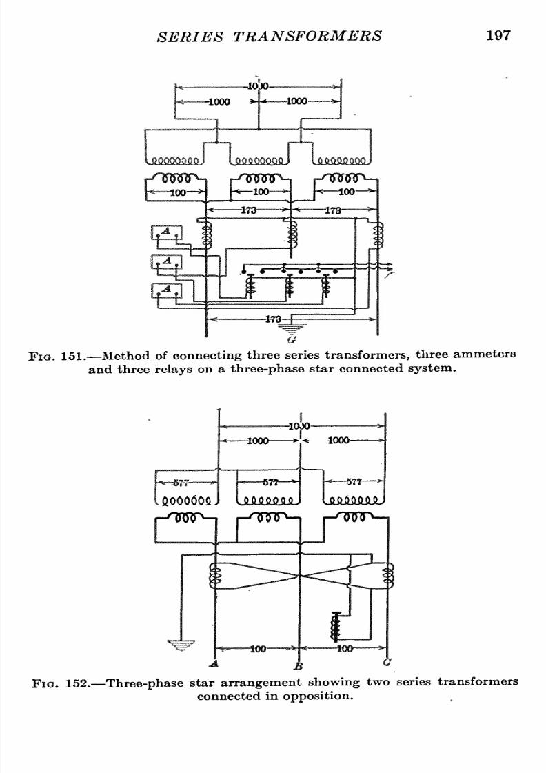
8/11/2019 Transformer Practice 1000194704
http://slidepdf.com/reader/full/transformer-practice-1000194704 209/290
SERIES
TRANSFORMERS
197
-10)0-
-1000
s
*
^1000
w
00
j h*^ioo
^
^
w
173
^
h
100 ^
-*
^173-
i_
-i-T
i=F
-173-
FiG.
151.
Method of
connecting
three
series
transformers,
three
ammeters
and three
relays
on
a
three-phase
star
connected
system.
-m-
-10)0-
1000
-577-^
.
QOQ06QQ
J
ULMMiJJlJ
UilMMJU
1000-
r-^wr -|
j-'Tnnp-|
-fws^^
t
Fig.
152.
Three-phase
star
arrangement
showing
two series
transformers
connected
in
opposition.

8/11/2019 Transformer Practice 1000194704
http://slidepdf.com/reader/full/transformer-practice-1000194704 210/290
198
STATIONARY
TRANSFORMERS
their
opposite
terminals
connected.
The
secondary
phase
relations
tend
to
operate
in
parallel
so
that
when
a
current
exists in
the
primary
of
one
transformer
a
current
will
also
exist
in
the
secondary
and
relay,
but
will
not
be
great
enough
to
operate
the
trip
coil.
If
a
short-circuit
should
occur
on
any
one
phase
of
the
two
outside
wires
A
C,
the
secondary
will become
over-oaded
and
its
voltage
will
rise
to
a
value
above
that
of
the
secondary
of the other
transformer;
this will
tend
to
reverse
the
current
in the latter
transformer,
which in
turn
will
allow the
v -
Six
phase
Fig.
153.
Method
of
connecting
two
series
transformers
with
instruments
and
relays
to
a
two-
or
three-phase
system
inducing
six-phase secondary
currents.
primary
flux
to
raise
the
voltage
to
the
value of
the
former
transformer;
this
voltage
will
cause
the
additional
current to
overload and
operate
the
relay.
This
current
value
will
not
be
twice
the
current
through
the
two
transformers,
but
will
be
the
algebraic
sum
of
the
currents at
120
degrees
apart,
or
\/S
times
the
current
in
each
leg.
For
example:
If
two
series
trans-ormers
are
wound
for 5
amperes
on
their
secondaries
with normal
current
through
their
primaries,
the
algebraic
sum
of
the
two
'currents
is
\/3X
5
=
8.66
amperes.
Fig.
153
shows
a
two-phase
arrangement
of
connecting
two

8/11/2019 Transformer Practice 1000194704
http://slidepdf.com/reader/full/transformer-practice-1000194704 211/290
SERIES TRANSFORMERS
199
series
transformers
for
working
instruments
and
relays.
It
will
be noticed in
all
the
connections
shown
that
the secondaries
of
all
transformers
are
grounded
on one
side.
In
Fig.
153
the
system
is
so
arranged
that
two-phase
or
three-
phase
currents
will
give
a
six-phase
secondary, depending
upon
the
connection
made
at
point
x.
The
series
transformer
con-ections
are so
arranged
that the
instruments
will work
satis-actorily
with
any
of the
two
independent
phase
currents.
The
Y
represents
the neutral
point
of the
secondary
power
Wm
a
UflflAJLr'
C^S
'-vAfliULr
r;
u]
1L
-vjjflfl4^
1
som
ABO
Fig. 154.
Three-phase
star
arrangement
showing
two series
transformers,
two
wattmeters,
and
three
ammeters.
transformers,
and
may
be
used
as a
neutral
wire
in connection
with
a
direct-current
system
of
supply.
Another
interesting
connection is
shown
in
Fig. 154,
in which
currents
are
measured in
the
three
phases by
the
use
of
two
series
transformers.
The
geometrical
sum
of
the
currents
in
the
primaries
where
the
two
series
transformers
are
installed,
is
measured
by
the
ammeter
shown
connected
to
the
grounded
side of
the
transformers.
The
value
obtained
is
that of the
current
through
the
middle
wire.
The
potential
sides
of
the two
wattmeters
may
be
connected
to
the
secondary
leads
of
two-shunt
transformers;
in
the
figure
they
are
shown connected
directly
to
the
mains.

8/11/2019 Transformer Practice 1000194704
http://slidepdf.com/reader/full/transformer-practice-1000194704 212/290
200
STATIONARY
TRANSFORMERS
In
general,
single
and
polyphase
combinations
of
series
trans-ormer
connections
are
covered
by
the
use
of
one
to
four
trans-ormers.
In
three-phase
work
either
the
star,
delta,open-delta,
reversed
open-delta
and
Z
connections
might
be
applied.
tM/'*^'^
y' ^^/ / ^'K.
'^^^^^^i
a
Fig. 155.
Three transformer
delta and
star
connections.
(See
figs.
155,
156,
157.)
The
connection
shown
in
Fig.
155 is
not
unlike the
ordinary
constant
potential
ransformer
delta.
In
this
connection the.
currents
in
the
secondary
leads
A and
B
are
the
same,
but
the
current
through
C
is
V3.
For
relays
it is
thought
to
be much better
than the delta connection.
-tUf^
W-
^
H^H^
^NHk
VM^ \
V-co^
Fig.
156
Two
transformer
V and inverted
V
connections.
It is
also
possible
to
measure
three-phase
currents
with
two
series
transforiners
and
only
one
ammeter.
The
arrangement
is
shown
in
Fig.
158.
To read
the
current
through
the
trans-ormer
on
the
left,
the
two
switches,
a
and
b,
are
closed.
To

8/11/2019 Transformer Practice 1000194704
http://slidepdf.com/reader/full/transformer-practice-1000194704 213/290
SERIES
TRANSFORMERS 201
read
the
current
in
the
middle
line,
h
and
c
are
closed;
the
current
through
the
transformer
on
the
right
is
measured
by
closing
the
two
switches,
c
and
d.
When
measurements
are
not
being
taken
it is
necessary
that
the
switches,
a
and
d,
should be
closed;
as
the
iron
of
the
two
transformers
is
worked
at
a
high degree
of
saturation,
which
produces
an
abnormally large
secondary voltage,
giving
rise
to
a
serious
heating
of
the
transformer.
Since series transformers
are
connected
directly
in series with
the
line,.
f
not
properly
installed,they
will
offer
a
convenient
path
for the
escape
of
high frequency charges
which
may
occur
on
the
line,
and
which
in
discharging,
not
only
burn
out
the
transformer,
but
are
likely
to
form
an arc
and
probably
cause a
fire,
or
loss
of
life.
rmWr
fHHi^
fWf^
^
W^
Fig.
157.
Three transformer
special
connections.
The
process
of
drying
out
air-insulated
series
transformers
is
accomplished
by
simply
passing
normal
current
through
the
winding
until
the
transformer
is
thoroughly
warmed. This
may
be
done
by
short-circuiting
he
secondary through
an
ammeter
and
sending
enough alternating
current
through
the
primary
to
give
normal
current
on
the
secondary,
the
primary
current
being
obtained
from
a
low
voltage
source.
If
not
convenient
to
obtain
low
voltage
alternating
current
the
same
result
may
be
accom-lished
by
passing
normal
direct
current
through
the
primary
long enough
to
thoroughly
warm
the
transformer.
In
case
of
oil-cooled
transformers,
the
winding
should
be
dried
out
by
this
same
process
before
the
transformer
is filled with
oil. In
doing
this
the
temperature
of the
coils
should
not
be
allowed
to
exceed 65
C,
which
may
mean
the
use
of
a
current
much less
than
normal, owing
to
the
fact
that
there
is
no
oil
in
the
transformer.

8/11/2019 Transformer Practice 1000194704
http://slidepdf.com/reader/full/transformer-practice-1000194704 214/290
202
STATIONARY TRANSFORMERS
All
secondaries
and
casings
of
transformers should
be
grounded,
and
likewise
the
instruments
to
which
they
are
connected.
This
serves
the double
purpose
of
protecting
the
switchboard
attend-,
ant
and
freeing
the
instruments
from the
effects of
electrostatic
charges
which
might
otherwise
collect
on
the
cases
and
cause
errors.
If
for
any
reason
it
becomes
necessary
to
remove
an
instru-ent
or
any
current
carrying
device
from
the
secondary
circuit
of
a
series
transformer,
the
secondary
should
be
short-circuited
r^rnjr^
r^iy^jr*-
r-npsv^
Fig. 158.
Method of
connecting
two
series
transformers
and
one
ammeter
to
a
three-phase
system,
to
measure
the
current
in
any
lead.
by
a
wire
or some
other
means.
Series transformers
should be
considered
as a
part
of the
line
circuit.
When
it
becomes
necessary
to
change
secondary
connections,
the
ground
wire
should be
inspected
to
see
that
it
is
in
good
condition.
The
operator
should
also
stand
in
a
dry
board
or
other
insulating
material.
By
reason
of
phase
displacement
in series
transformers,
watt-eters,
when
used
with
series
transformers,
will
have
certain
errors
due
to
such
displacement.
The
following
table
applies
to
certain
types
of series
transformers,
the actual
percentage
of

8/11/2019 Transformer Practice 1000194704
http://slidepdf.com/reader/full/transformer-practice-1000194704 215/290

8/11/2019 Transformer Practice 1000194704
http://slidepdf.com/reader/full/transformer-practice-1000194704 216/290
204
STATIONARY
TRANSFORMERS
TABLE
VIII
At
power-factors
f less
than 50
per
cent,
the
errors
will
greatly
increase.
It
will
be
seen
that
if
the
wattmeter
is
calibrated
with
the
series
transformer,
greater
accuracy may
be obtained
when
used
in
a
circuit of
approximately
the
same
power
factor,
but
that the
error
at
a
lower
power-factor
becomes
greater.
The
plussign
(
+
)
means
that the
wattmeter
will indicate
more
than
the
true
power
by
the
percentage
shown.
The
minus
sign
( )
means
that
the
wattmeter
will
indicate
error
in
the
opposite
direction.
Excepting
(d)
which indicates
a
wound
primary
type
trans-ormer,
(a),
(h)
and
(c)
are
for
transformers
of the
open
type
intended
to
slip
over
bus-bar
or
switch-stud
as
well
as
the
wound
primary
type
transformer
(5
amp.
secondary).
It issometimes desired
to
use
for
meter
test
and other
puiposes,
inverted
series
transformers;
that
is,
step-up
current trans-ormer.
Fig.
159
shows
an
arrangement
using
two
series
trans-ormers
of
any
desired ratio
but
equal;
No.
2
transformer
is
inverted,
and, depending
on
the
ratio
of
transformation,
ay
be
employed
to
step
up
the
current to
any
desired
value.
Assum-ng
that
both
transformers
are
for
40
to
1
ratio
(200-5
amp.),
it is
evident,
from
the
diagram
that the standard
testing
instrument
in
No.
1
transformer
circuit
has
a
5-ampere
current
coil and the
service
meter 200
amperes
in its
current
coil
when
a
5-ampere
load
is
flowing
through
the
circuit
load
b.
For
some
time
past,
the
series
transformer
has been used
for
low-voltage
scries
street
lighting
in
connection with
series
arc
lighting
systems.
For
the
purpose
of
lighting,
ts
primary
winding
is
connected
Tables
VI,
VII
and
VIII
are
representative
of
a
certain
type
of
series
transformer
and
should therefore
not be
considered
general.
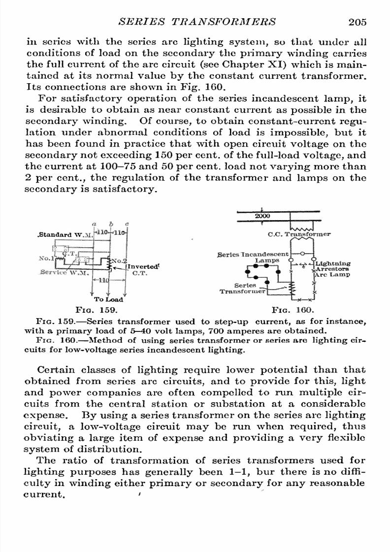
8/11/2019 Transformer Practice 1000194704
http://slidepdf.com/reader/full/transformer-practice-1000194704 217/290
SERIES TRANSFORMERS
205
in
series with
the
series
arc
lighting
system,
so
that
under
all
conditions
of
load
on
the
secondary
the
primary winding
carries
the
full
current
of the
arc
circuit
(see
Chapter
XI)
which
is main-ained
at
its
normal value
by
the
constant
current transformer.
Its
connections
are
shown
in
Fig.
160.
For
satisfactoryoperation
of
the
series
incandescent
lamp,
it
is
desirable
to
obtain
as near
constant
current
as
possible
in
the
secondary
winding.
Of
course,
to
obtain
constant-current
regu-ation
under
abnormal
conditions
of
load
is
impossible,
but it
has
been
found
in
practice
that
with
open
circuit
voltage
on
the
secondary
not
exceeding
150
per
cent,
of the
full-load
voltage,
and
the current at
100-75
and
50
per
cent,
load
not
varying
more
than
2
per
cent.,
the
regulation
of
the
transformer
and
lamps
on
the
secondary
is
satisfactory.
.standard
W,
~_l
In
verterf
To
Load
Fig.
159.
Fig.
Fig.
159.
Series
transformer used
to
step-up
current,
as
for
instance,
with
a
primary
load
of
5-40
volt
lamps,
700
amperes
are
obtained.
Fig.
160.
Method
of
using
series
transformer
or
series
arc
lighting
cir-uits
for
low-voltage
series incandescent
lighting.
Certain
classes of
lightingrequire
lower
potential
than that
obtained
from series
arc
circuits,
and
to
provide
for
this,
light
and
power
companies
are
often
compelled
to
run
multiple
cir-uits
from
the
central
station
or
substation
at
a
considerable
expense.
By
using
a
series
transformer
on
the
series
arc
lighting
circuit,
a
low-voltage
circuit
may
be
run
when
required,
thus
obviating
a
large
item of
expense
and
providing
a
very
flexible
system
of
distribution.
The ratio
of transformation of
series transformers used for
lighting
purposes
has
generally
been
1-1,
bur there
is
no
diffi-ulty
in
winding
either
primary
or
secondary
for
any
reasonable
current.
'

8/11/2019 Transformer Practice 1000194704
http://slidepdf.com/reader/full/transformer-practice-1000194704 218/290
206
STATIONARY TRANSFORMERS
The
core
of
this
transformer
is of
the shell
type,
built
up
of
circular
punchings
with
two
symmetrical pieces
in
each
layer.
On
the
center
leg
or
tognue
of
the
core are
assembled the form-
wound
coils.
The
primary
coil
fits
simply
over
the
secondarp
coil,
but
is
so
insulated that
it will withstand
a
break-down
test
of
20,000
volts
to
the
secondary
coil
and also
to
the
core.
Its
appearance
is
not
unlike
the well-known
telephone
line
insulating
transformer
which is used
in connection with
long-distance
high-voltage
transmission
work.
In
this
series
transformer
there
exists
a
drooping
voltage
char-cteristic
in
the
secondary.
Its
purpose
is
to
limit
the
open-
circuit
voltage
on
the
secondary.
It
has
been
obtained
by
so
proportioning
the
magnetic
circuit
that
the
section
is
contracted
in
several
parts
to
permit
saturation
of the iron
with
no
current
in
the
secondary
winding.
There
exist
quite
a
number
of
meter
connections which
may
be
used
on
power
transformer
systems.
Some of
these
are
given
below:
series
and
potential
ransformers
being
used
in
each
case.
Fig.
161(A)
shows
the
simplest
three-wire
three-phase
meter
arrangement,
in which
a
single-phase
wattmeter
has
its
potential
coil
connected
to
the
secondary
of
a
potential
ransformer,
and
its
current
coil
to
the
secondary
of
a
series
transformer.
If the
power
transform
should have
an
accessible
neutral
point,
at
the
location
x,
the
potential
ransformer
may
be
connected
according
to
the dotted
line.
Fig.
161(B)
shows the
next
simplest
three-wire
three-phase
wattmeter
arrangement,
in
which
two
single-phase
wattmeters
are
involved.
This method of
measuring
electrical
energy
in
three-phase
circuits
for
any
condition
of
unbalanced
voltage
or
current
is
the
correct
one.
Fig
161(C)
connection
is
for
a
three-wire
three-phase
system.
The
wattmeter
has its
current
coil
connected
to
one
phase
through
a
series
transformer
(c.t.),
and
its
potential
coil
to
a
Y
impe-ance,
each
branch
of
which
has
equal
reactance
and
resistance
such
as
to
give
the
proper
voltage
to
the
potential
coil
of
the
meter.
Fig
161(D)
connection is
not
unlike
(B).
The
polyphase
or
two-element
wattmeter
is.
employed
here,
and should
always
be
used
in
preference
to two
single-phase
meters.
It has
a
slightly
better
accuracy
if
we
consider
that
the record
of the
meter
as a
whole
is obtained without
the
possibility
f
error
that
comes
from

8/11/2019 Transformer Practice 1000194704
http://slidepdf.com/reader/full/transformer-practice-1000194704 219/290
SERIES
TRANSFORMERS
207
P.W.M.
W.M.1
W,M
Fig.
161.
Other
important
uses
for
series transformers
on
three-phase
systems.

8/11/2019 Transformer Practice 1000194704
http://slidepdf.com/reader/full/transformer-practice-1000194704 220/290
208
STATIONARY
TRANSFORMERS
reading
the
two
single-phase
meters
separately
and
adding
their
sum
total
together
afterward.
Fig
1Q1{E)
and
(F)
show
two
arrangements
of
the three
single-
phase
wattmeter
method
for
a
three-phase
three-wire
system.
The
potential
transformers
are
connected
in
star-star.
This
method
is
not
recommended
because
of
unequal loading
which
might
occur
on
the
secondary
side. With
unbzlanced load
on
the
secondary,
the
voltages might
become
very
unequal,
and with
an
accidental
short-circuit
on
one
transformer
its
primary
impedence
may
be
so
reduced that the
remaining
two
transformers would
be
subjected
to
almost
\/S
times their
normal
voltage.
Fig
161
(GO
shows
a
three-
wattmeter
method
in which
three
series
transformers,
and
three
potential
transformers
are
used,
the
latter
being
connected
in
star-delta.
This
method should
always
be
used
in
preference
to
methods
(E)
and
(F)
for the
reason
the
balanced
voltages
on
the
primary are
established
by
exchange
of
current
through
the
secondary
circuits
of
the three
transformers
in
case
the
secondary
loads
are
unbalanced.
Abnormal
voltages
are
prevented
in
the
individual
transformers and
meters.
Fig.
1Q1{H)
shows
a
four-wire
three-phase,
three-wattmeter
method.
The
potential
transformers
are
connected
in
star-star,
but the
objection
referred
to
in
(E)
and
(F)
is
practically
elimi-ated.
The
arrangement
is
the
same as
three
independent
single-
phase
systems
with
one
conductor
of each
phase
combined into
a
common
return.
This
method of
measuring
energy
is considered
to
be
superior
to
the three-wattmeter
method
shown
in
(E),
(F),
and
(G),
for the
reason
that
no
inter-connection
of
potential
transformers
is
required
and
because
the
wattmeters cannot
be
subjected
to
variations
of
voltage
greater
than those
properly
belonging
to
the
circuit.
Fig
161(7)
shows
a
four-
wire,
three-phase, polyphase
wattmeter
method.
This
method
is
preferable
to
method
(H)
and offers
greater
simplicity
and
convenience.
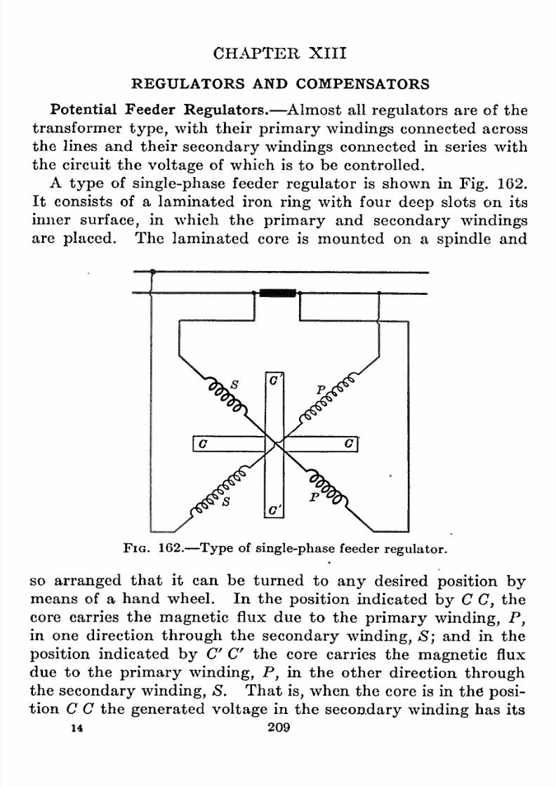
8/11/2019 Transformer Practice 1000194704
http://slidepdf.com/reader/full/transformer-practice-1000194704 221/290
CH.APTER
XIII
REGULATORS
AND
COMPENSATORS
Potential
Feeder
Regulators.
Almost
all
regulators are
of
the
transformer
type,
with their
primary
windings
connected
across
the
lines
and
their
secondary
windings
connected
in series with
the
circuit
the
voltage
of which is
to
be
controlled,
A
type
of
single-phase
feeder
regulator
is
shown
in
Fig.
162.
It
consists of
a
laminated iron
ring
with
four
deep
slots
on
its
inner
surface,
in
which
the
primary
and
secondary
windings
are
placed.
The
laminated
core
is mounted
on
a
spindle
and
Fig.
162.
Type
of
single-phase
feeder
regulator.
so
arranged
that it
can
be
turned
to
any
desired
position
by
means
of
a
hand
wheel. In
the
position
indicated
by
C
C,
the
core
carries the
magnetic
flux
due
to
the
primary winding,
P,
in
one
direction
through
the
secondary
winding,
S;
and in the
position
indicated
by
C C the
core
carries the
magnetic
flux
due
to
the
primary
winding,
P,
in
the
other
direction
through
the
secondary
winding,
S.
That
is,
when the
core
is in
the
posi-ion
C C the
generated voltage
in
the
secondary winding
has
its
14
209

8/11/2019 Transformer Practice 1000194704
http://slidepdf.com/reader/full/transformer-practice-1000194704 222/290
210
STATIONARY TRANSFORMERS
highest
value.
When
the
core
is
midway
between
C C and
C
C
the
generated
voltage
in
the
secondary
winding
is
zero,
and the
feeder
voltage
is
not
affected. When the
core
is
in
the
position,
C C
,
the
generated voltage
in
the
secondary
winding
is
again
at
its
greatest
value,
but
in
such
a
direction
as
to
oppose
the
gener-tor
voltage.
On
account
of
the
air-gap
between
the
primary
and
secondary
windings,
inductive
reactance
is intro-uced
in
the
line which
requires
com-ensating.
The
Stillwell
regulator
is
another
type
of
transformer for
raising
and lower-ng
the
voltage
of feeder circuits.
It
consists
of
a
primary
winding
which
is
connected
across
the
feeder
circuit,
and
a
secondary
winding
in series
with
the
circuit
the
voltage
of
which
is
to
be
varied.
By
means
of
a
switch
arm,
more or
less of the
secondary
winding
may
be
introduced into
the
circuit,
hus
boosting
by
a
corresponding
amount
the
voltage
of
the
generator.
A
reverse
switch is
provided
to
which
the
primary
winding
is
connected,
so
that the volt-ge
may be added
by
moving
the switch
arm
to
the
right,
and
subtracted
by
moving
the
switch
arm
to
the left.
A
regulator
built
along
the lines mentioned
above,
with
an
arrangement
for
connecting
the
various sections
of
the
secondary
winding
to
a
dial switch
and
reversingswitch,
is
shown
in
Fig.
163.
The feeder
potential
can
be controlled
in
the
following
manner:
Starting
with
the
regulator
in
position
of
maximum
boost,
that
is,
with
the
dial switch turned
to
the
extreme
left
as
far
as
it will
go,
a
continuous
right-hand
movement
of
the
dial
switch
for
two
complete
revolutions
is
obtained.
During
the
first
revolution the
switch
cut
outs, step
by
step,
the
ten
sections
of
the
secondary
winding.
When
the first
revolution has
been
completed,
the
voltage
on
the feeder
is
the
same as
that
of
the
generator,
no
secondary
winding
being
included.
A further
movement
of
the
switch in
the
same
direction
automatically
throws
a
reversing
switch;
and
continuing
the
movement
of
the
dial
switch,
stillin
the
same
direction,
the
secondary
windings
Fig.
163.
Type
of Still-
well
regulator.

8/11/2019 Transformer Practice 1000194704
http://slidepdf.com/reader/full/transformer-practice-1000194704 223/290

8/11/2019 Transformer Practice 1000194704
http://slidepdf.com/reader/full/transformer-practice-1000194704 224/290
212
STATIONARY
TRANSFORMERS
Fig.
165.
Further,
by
bringing
a
number of leads
from
parts
of
the
winding,
2,
8,
the
secondary
voltage,
1,
3,
may
be
in-reased
or
decreased
step by
step
as
the
different
leads
of
2,
3,
are
connected
to
the
secondary
circuit.
In
Fig.
165
is
shown
the
connections
of
this form
of
regulator,
or
compensator.
1, 2,
represents
the
primary
winding
con-ected
across
the
circuit.
From
a
portion
of the
secondary
winding,
3, 4,
taps
are
brought
to
the
contact
blocks
shown
in
the
diagram.
The
two
arms,
7,
8,
connect
these
ZZ
contact
blocks
to two
sliding
contacts,
5,
6.
1000
The
arms,
7,
8,
may
be
operated by
a
handwheel,
3TW55jn*
ne
in direct
contact
and
the
other
through
a
^^
gearing,
so
that
a
rotation
of the
handwheel
turns
one arm
clockwise
and the other
counter-
*
^^
H
clockwise.
-pj^
jgg
rp
The
secondary voltage
of the
circuit
is
that
of
series incandes-
^^ *^
primary,
increased
or
decreased
by
the
cent
regulator
voltage
between the arms,
7,
8.
In the neutral
that
reduces
the
position,
oth
arms
rest
on one
central
contact
initial
primary
bi^g]^^
^nd
the difference
of
potential
between
them
is
zero.
In order
to
decrease
the
voltage
at
the
lamps,
the
handwheel
is
turned
to
the
right,
and the
volt-ge
decreased
step by step,
until
the
final
position
is
reached
with
each
arm on an
extreme
contact
block.
To
increase
the
voltage
at
the
lamps,
the handwheel is
turned
to
the
left,
the
two
arms
being
gradually separated
on
the
contact
blocks;
and the
difference
of
potential
between the
arms
is effected
step by
step
until in
the final
position,
ach
arm
rests
on an ex-reme
contact,
and
the
secondary
winding
is connected
into
the
circuit
and
its
total
voltage
thus
added
to
the
initial
voltage
of
the
system.
This
type
of
regulator,
as
will
be
seen,
is in
the
order of
an
ordinary
auto-transformer
with
regulating
taps
ar-anged
on
its
secondary
winding.
The
induction
type
regulator
differs
from the transformer
type
in
that
all
the
primary
and
secondary
windings
are
con-tantly
in
use.
There
are
types
that
vary
the
secondary
voltage
either
by
moving
part
of
the
iron
core or
one
of
the
windings,
or
one
of
the
windings (primary
or
secondary)
and
part
of
the
iron
core;
the whole
or
part
of the
magnetic
flux
generated
by
the
primary
threads the
secondary according
to
the
position
of
the
moving
part.

8/11/2019 Transformer Practice 1000194704
http://slidepdf.com/reader/full/transformer-practice-1000194704 225/290
REGULATORS AND
COMPENSATORS
213
This
type
of
regulator
is
either self-cooled
oil
immersed,
oil-
immersed
water-cooled,
or
forced
air-cooled
depending
on
the
capacity.
Single-phase
regulators
have
only
one
excitation
winding,
the
magnetizing
flux
is
an
alternating
one
and
its direction
is
always
parallel
to
that
diameter
of
the
movable
core
which
passes
through
the
center
of the
exciting
coil,
ut
its
direction
may
be
varied
with
respect
to
the
stationary
core,
and, consequently,
with
the
respect
to
the
stationary
or
series
winding.
With
the
armature
in
such
a
relation
to
the
field
that
the
primary
winding
induces
a
flux
opposed
to
that
induced
by
the
secondary,
the
voltage
induced
by
the
primary
in
the
secondary
is
added
directly
to
the
line
voltage,
but
is
subtracted when
th6
direction
of the flux is
the
same,
the
complete
range
being
obtained
by
rotating
the
armature
through
an
angle
of
180
degrees.
As
the
core
is
rotated
gradually,
the
relative direction
of
the
primary flux, and, consequently,
the
amount
forced
through
the
secondary
coils,
s
similarly
varied and
produces
a
gradually
varying
voltage
in
the
secondary
from
the
maximum
positive,
through
zero,
to
the
maximum
negative
value. The
induced
voltage,is,however,
added
directly
to,
or
subtracted
directly
from
the
line
voltage.
The
primary
or
rotating
core
contains
two
windings;
the
active
windings
connected
across
the
line,
and
a
second
winding
short-
circuited
on
itself
and
arranged
at
right angles
to
the
active
winding.
The
object
of
this short-circuited
winding
is
to
de-rease
the
reactance
of
the
regulator,
and
its
operation
is
as
follows:
As the
primary
and the
short-circuited
windings
are
both
on
the
movable
core
and
permanently
.fixed at
right
angles
to
each
other,
the flux
generated by
the
primary
passes
on
either
side
of
the
short-circuited
coil,
nd
is,
therefore,
ot affected
by
it
in
any
way
whatever;
for
as
long
as
no
flux
passes
through
this
coil
there
is
no
current
in
it.
This
condition
is,
however, only
true
when
the
armature
is
in
the
maximum
boost
or
maximum
lower
position
with
current
in
the
series
winding,
and
in
any
position
of the
armature
with
no
current
in
the
secondary.
With
the
armature
in
the neutral
or no
boost
or
lower
position
the
flux
generated
by
the
current
in
the
secondary
passes
equally
on
either
side
of the
primary
coils,
which
cannot,
therefore,
neutralize
the
flux
generated by
the
secondary.
If
the
primary
core were
not
provided
^ith
a
short-circuited

8/11/2019 Transformer Practice 1000194704
http://slidepdf.com/reader/full/transformer-practice-1000194704 226/290
214
STATIONARY
TRANSFORMERS
winding,
and rotated
from
maximum
position
o
as
to
reduce
the
primary
flux
passing
through
the
secondary,
and
if
the
line
current
remained
constant,
a
gradually
increasing
voltage
would
be
required
to
force the
current
through
the
series
windings,
and
a
correspondingly
increasing
flux
would have
to
be
generated.
This
voltage
would
become
a
maximum
with
the
armature
in
the
neutral
position,
ue
to
the
fact that
in this
position
the
primary
windings
are
at
right
angles
to
the
series
windings
and
therefore
entirely
out
of
inductive relation
to
them.
The
current
in
the
secondary, therefore,
would
act
as a
magnetizing
current,
and
a
considerable
part
of
the
line
voltage
would have
to
be
used
to
force
the
current
through
these coils.
The
voltage
so
absorbed
would be
at
right
angles
to
the
line
voltage,
and the
result
would be
a
poor power
factor
on
the feeder.
The
short-circuited
coil
on
the
armature
which is
in
a
direct
inductive
relation
to
the series
coils
when the
armature
is in
the
neutral
position,
cts
as a
short-circuit
on
the
secondary
winding,
^-E,
Fig.
166.
Phase
positions
of
primary
and
secondary
voltages
of
a
single-
phase
induction
regulator.
and
thereby
reduces the
voltage
necessary
to
force
full load
current
through
this
winding
to
only
a
trifle
more-
than that
represented
by
the
resistance
drop
across
the
secondary
and
short-circuited
windings.
This
short-circuiting
f
the
secondary
is
gradual,
from
zero
to
the
maximum
boosting
position
of the
regulator
to
the
maximum
short-circuiting
n the neutral
position,
so
that
by
the
combined
effect of
the
primary
and
short-circuited
coils
the
reactance
of
the
secondary
is
kept
v/ithin
reasonable
limits.
The
operation
of the
short-circuited
coil
does
not
increase the
losses in
the
regulator,
but
rather tends
to
keep
them
constant
for
a
given
secondary
circuit.
In
rotating
the
armature
from
either
maximum
to
the
neutral
position,
the
current
in
the
primary
diminishes
as
the
current
in
the
short-circuited
coil
increases,
o
that the
total
ampere-turns
of
the
primary
plus

8/11/2019 Transformer Practice 1000194704
http://slidepdf.com/reader/full/transformer-practice-1000194704 227/290
REGULATORS AND
COMPENSATORS
215
the
ampere-turns
of
the
short-circuited
winding
are
always
approximately
equal
to
the
ampere-turns
of
the
secondary.
In
Fig.
166
there
is
shown
graphically
the values
and
time-
phase
position
of
primary
and
secondary
voltages
of
a
single-
phase
induction
regulator.
When
the
mechanical
position
in electrical
degrees
of
the
moving
part
is shifted
to
0
F
on
0
X
following
the
curve
of the
semi-circle
in
the
position
of
negative
boost,
or
0 Y'
and
0
X'
in
the
position
of
positive
boost,
the
secondary
voltage
can
be
considered
to
have
the
values
0
C and
0
A
respectively,
nd
0
C
and
0 A'
respectively.
When the
mechanical
part
occupies
a
mechanical
position
of
90
electrical
degrees
from
the
position
0
E
s' and 0 E
s
the
value
0
B oi
the
secondary voltage
is
zero,
because the flux due
to
the
primary
exciting
current
passes
through
the
secondary
core
parallel
to
the
secondary
windings.
The
resultant
voltage
is
equal
to
the
primary
voltage.
The
kilowatt
capacity
of
any
regulator
is
equal
to
the
normal
line
current to
be
regulated
times
the
maximum
boost of
the
regulator,
and
as
the
lower
is
always equal
to
the
boost,
the
total
range
is
equal
to
twice
the
kilowatt
capacity
or
100
per
cent,
with
a
1
to
2
ratio.
Kilowatt
capacity
of
a
single-phaseregulator
is maximum
boost
or
lower
times
the
current,
or
the
maximum
boost
or
lower
might
be
expressed
in
terms
of
kilowatts divided
by
the
secondary
current.
For
a
two-phase
type
it
is
one-half this
amount.
In
a
three-phase type
the boost
or
lower
across
the
lines
is
equal
to
the
regulatorcapacity
in kilowatts
multiplied
by
V
3
and
divided
by
the
secondary
current.
Regulators
of the
induction
type
should
not
be
used
for
any
other
primary
voltage
or
frequency
differing
more
than
10
per
cent,
from that for
which
they
are
designed,
because an
increase in
voltage
or
a
decrease
in
frequency
increases
the
magnetizing
current
and
the
losses
and
an
increase in
frequency
increases
the
impedance.
The
deviation
of
10
per
cent,
allowed
must
not
occur
in
both the
frequency
and
the
voltage
unless
these
deviations tend
to
neutralize
each other. For
instance,
regulator
should
not
be
subjected
to
a
10
per
cent,
increase
in
voltage
and the
same
per
cent,
decrease
in
frequency,
but
it
will
operate
satisfactorily
f
both
voltage
and
frequency
are
increased
within the
aEiount
given.

8/11/2019 Transformer Practice 1000194704
http://slidepdf.com/reader/full/transformer-practice-1000194704 228/290
216
STATIONARY
TRANSFORMERS
Induction
regulators
may
be
operated by
hand,
either
directly
or through
a
sprocket
wheel and
chain;
by
a
hand-controlled
motor,
or
automatically-controlled
otor.
If
operated
by
hand
controlled
motor,
the
motor
may
be
of the
alternating-current
or
direct-current
type,
but
preferably
of the
alternating-current
type
and
polyphase.
If
automatically
controlled,
the
operating
motor
should
preferably
be of the
polyphase
type
as
the direct-
current motor
is
not
very
well
adapted
for
this
purpose.
When
the
regulator
is
operated
by
a
motor,
the
motor
should be
con-rolled
by
a
double-pole
double-throw
switch
mounted
on
the
switchboard
or
in
any
other
convenient
location.
Closing
the
switch
one
way
or
the other
will
start
the
motor
so
as
to
operate
the
regulator
to
obtain
a
boost
or
lower
in
the
line
voltage
as
may
be
desired,
and when the
correct
line
voltage
is
obtained
the
regulator
movement
should
be
stopped
by
opening
_L
Regulators
Tt
r
egruiaiors
-Eie-
-E e-
Eegixlators
-E^e
Fig. 167.
Connections of
single-phase
regulators
operating
on a
three-phase
system.
the
switch.
Generally
a
limit switch is
provided
which
stops
the
movement
of the
regulatorby
opening
the
motor
circuit
as
soon as
the
regulator
has
reached
either
the
extreme
positions
depending
on
the
direction
of
rotation,
but
which
automatically
closes
the
circuit
again
as
soon as
the
regulator
armature
recedes
from the
extreme
positions.
The
operation
of each
limit switch
does
not
interfere
with
the movement
of
the
regulator
in
the
direction
opposite
to
which it
may
be
going.
When
a
single-phase
regulator
is
used
in
one
phase
of
a
three-
phase
system,
the
secondary
wiring
is
connected in
series
with
the line and the
primary
between
the
lines,
ee Fig.
167.
Under
these
conditions there
is
a
difference
in
phase
between
the
current
in
the
two
windings
and the
effective
voltage
of
the
secondary
is therefore reduced
from
its normal value.
If
three
single-phase
regulators
are
used,
each
phase
can
be

8/11/2019 Transformer Practice 1000194704
http://slidepdf.com/reader/full/transformer-practice-1000194704 229/290
REGULATORS AND
COMPENSATORS
217
adjusted
to
the
range
equal
to
the
effective
range
of the
regulator,
so
that the
voltage
between the
phases
is
not
that due
to
the
effective
voltage
per
regulator,
ut
that
due
to
the
effective
voltage
of each
regulator
times
Vo.
In
this
case,
if
10
per
cent,
regu-ation
across
the
phases
of
a
three-phase
three-wire
system
is
desired,
only
57.7
per
cent,
of the
10
per
cent,
regulation
per
line is
needed;
thus,
the
boosting
or
lowering
need
not
have
a
greater
rating
than
3
to
7,5
per
cent,
instead
of
10
per
cent,
which is
the
size
necessary
where
one
regulator
is
used.
In
general
the
capacity
in
kw.
of
a
three-phaseregulator
is
rated
at
E.I.\/S,
here E
is
the volts
boost
or
lower
and I the
amperes
in
feeder
circuit.
For
six-phase
rotary
converter
service,
kw.
capacity
of
regulator
is:
(double-delta
connection)
=J5J.
7.
3.46
(29)
and
(diametricalconnection)
=E.
I.
3
(30).
For
fKjlyphase
circuits
the
system
may
be
regulated
by
intro-ucing
the so-called
induction
regulator.
This
form
of
regulator
has
a
primary
and
a
secondary
winding.
The
primary
winding
is
connected
across
the
main
line,
and
the
secondary
winding
in series
with
the
circuit.
The
voltage generated
in
each
phase
of the
secondary winding
is
constant,
but
by
varying
the
relative
positions
of
the
primary
and
secondary,
the effect-ve
voltage
of
any
phase
of
the
secondary
on
its circuit is
varied
from
maximum
boosting
to
zero
and
to
maximum
lowering.
In
order
to
avoid
the
trouble of
adjusting
the
voltages
when
each
phase
is controlled
independently,
polyphase regulators
are
arranged
to
change
the
voltage
in
all
phases
simultaneously
They
can
be
operated by
hand wheels
or
motors.
When
operated
by
hand,
the movable
core
is
rotated
by
means
of
a
handwheel
and
shaft.
When it is
desired
to
operate
the
regulator
from
a
distant
point,
the
apparatus
is
fitted
with
a
small
motor
which
is
arranged through
suitable
gearing
to turn
the
movable
core.
The
motor
may
be
of
the
direct-current
or
induction
type,
and
controlled
at
any
convenient
place.
The
theory
of
this
form of
regulator
is
described
graphically
in
Fig.
168
in
which the
voltage
of
one
phase
of
the
regulator
is,
o
=
generator
voltage
or
the
e.m.f.
impressed
on
the
primary:
ao
= e.m.f.
generated
in the
secondary
windings,
and
is
constant
with
constant
generator
e.m.f.
:
6'a'
=
secondary
e.m.f.
in
phase
with
the
generator
e.m.f.
:e'a'
=
line
e.m.f.,
or
resultant
of
the
generator
e.m.f.
and
the
secondary
e.m.f.
The
construction
of
the
regulator
is
such that the
secondary

8/11/2019 Transformer Practice 1000194704
http://slidepdf.com/reader/full/transformer-practice-1000194704 230/290
218
STATIONARY
TRANSFORMERS
voltage,
oa,
is
made
to
assume
any
desired
phase
relation
to
the
primary
e.m.f.,
as
of,
oh,
oc,
etc.
When
its
phase
relation is
as
represented
by
of,
which
is
the
position
when
the north
poles
and
the
south
poles
of
the
primary
and
secondary
windings
are
opposite,
the
secondary voltage
is in
phase
with
the
primary
voltage
and is
added
directly
o
that of
the
generator.
The
regulator
is
then
said
to
be
in
the
position
of
maximum
boost,
and
by
rotating
the
armature
with
reference
to
the
fields,
the
phase
relation
can
be
changed
to
any
extent
between
this
and
directly
opposed voltages.
When the
voltage
of
the
secondary
is
directly
pposed
to
that
of
the
primary,
its
phase
relation is
as
e'
I'
a'
Fig,
168.
Graphical
representation
of
an
induction
regulator,
represented
by
o
d
in
the
diagram,
while
o
h
represents
the
shape
relation
of the
secondary
when
in
the neutral
position.
The
electrical
design
of the
induction
regulator
is
very
similar
to
that
of the
induction
motor.
Its
efficiency
is
somewhat
higher
than
the
average
induction
motor
of the
same
rating.
The
primary
winding
is
placed
on
the movable
core
and
has
either
a
closed
delta
or
star
connection,
while the
secondary
or
stationary
winding
is
placed
on
the
stationary
core
and
is
an
open
winding,
each
section
or
phase
being
connected
in
series with
the
corre-ponding
phase
of the
line.
The
maximum
arc
through
which
the
primary
moves
is
60
degrees
for
a
six-pole
and
90
degrees
for
a
four-pole.
Induction
potential
regulators
are
built
for
single-phase,
two-phase,
three-
phase
and
six-phase
circuits.
Compensators
are
used
in connection with
starting
alternating-
current
motors,
and
to
some
extent
they
are
used
in
connection
with
voltmeters
in
the
generating
station.
Compensators
for
startingalternating-current
motors
consist
of
an
inductive
winding
with
taps..
For
polyphase
work
the

8/11/2019 Transformer Practice 1000194704
http://slidepdf.com/reader/full/transformer-practice-1000194704 231/290

8/11/2019 Transformer Practice 1000194704
http://slidepdf.com/reader/full/transformer-practice-1000194704 232/290
220
STATIONARY
TUANSFORMERS
be thrown
over
to
the
running
position;
he
compensator
winding
is
then
cut out
and the
motor
is
connected
to
the
line
through
suitable
fuses
or
circuit breakers. The
switch is
generally
provided
with
a
safety
device which
is
used
to
prevent
the
operator
from
throwing
the
motor
directly
on
the
line,thereby
causing
a
rush of
current.
Compensators
are
designed
to
bring
the
motor
up
to
speed
within
one
minute
after
the
switch
has been thrown
into
the
starting
position.
It
is
important
that the
switch
be
kept
in
the
starting
position
until
the
motor
has
finished
accelerating,
to
prevent
an
unnecessary
rush of
current
when the
switch is
thrown
to
the
running
position.
In
two-phase
compensators
the
line is
connected
to
the ends
of
the
two
coils,
and the
starting
connections
of
the
motor to
the
taps
as
shown
in
Fig.
170.
The
switch
for
operating
the
starting
compensator
and
motor
is
the
same as
that
used
on
the
three-phase
service.
Other
designs
are
used,
one
of
which
operates
the
compensator
as
follows:
For
starting
the
motor
the
switch
handle
moves
from
the
off
position
to the
first
starting position,
where
a
low
voltage
is
applied
to
the
motor;
then
to
a
second
startingposition
where
a
higher
voltage
is
applied;
and
then
to
the
running
position,
where
the
motor
is
connected
directly
across
the
line,
the
compensator
being
disconnected
from
the
circuit.
For
stopping,
the
switch
handle
is
moved
to
a
notch still further
along
than the
running
position,
the
movement
of
the
switch
handle
being
in
the
same
direction
as
in
starting.
In
the latter
position
the
switch
handle
is released
to
that
it
can
be
moved
back
to
the
off
position
ready
to
start
again.
The
other
form of
compensator
used
to
indicate the
variations
of
voltage
at
the
point
of distribution
under all
conditions
of
load
without
appreciable
error
between no-load and
overload,
consists
of
three
parts:
a
series
transformer,
a
variable
reactance,
and
a
variable resistance.
The
compensator
is
adjusted
to
allow for
the resistance
and
inductive
reactance
of
the
line. If
these
are
properly
adjusted,
a
local
circuit
is
obtained
corre-ponding
exactly
with
the
line
circuit,
nd
any
change
in
the
line
produces
a
corresponding change
in
the
local
circuit,
ausing
the
voltmeter
always
to
indicate the
potential
at
the
end of
the
line
or
center
of
distribution,
according
to
which
is
desired.
It
is
well
known
that
the
drop
in
a
direct-current
circuit
is
dependent

8/11/2019 Transformer Practice 1000194704
http://slidepdf.com/reader/full/transformer-practice-1000194704 233/290

8/11/2019 Transformer Practice 1000194704
http://slidepdf.com/reader/full/transformer-practice-1000194704 234/290
222
STATIONARY
TRANSFORMERS
Its
connections
proper,
as
used
in
practice
at
the
present
time
are
shown
in
Fig.
172,
Each
line
of
which
the
voltage
at
the
center
of
distribution
is
to
be
indicated
or
recorded
in
the
station,
must
be
provided
with
a
voltmeter
as
shown
in
Fig.
172,
No.
1,
which
must
be
adjusted
for
the
ohmic
and
reactive
drop
of
each
line
respectively.
For
example,
take
such
a
line
giving
the
factors
shown
in
Fig.
173;
where
R
is ohmic'
resistance
of
10,
Xs
is
the
reactance
of
10
ohms,
and
E
is
the load
voltage.
To fulfil
the
conditions of
E
=
100,
it is
necessary
that
the
voltage
of
supply
or
generator
voltage
be
increased
to
nearly 110.5,
and the
voltmeter
No.
2 of
Fig.
160
will indicate this
value.
With
unity
power
factor it
will
be
noted that the
total
live
drop
is
due
almost
entirely
to
the
line resistance
R,
and
is
prac-ically
independent
of
the
line
reactance.
Current
Transformer
j;
fji
Line
Drop
Compensator
Fig.
172.
Connections
for
live-drop
compensator.
As the
power
factor of the
line
decreases,
the
effective
voltage
produced by
the
reactance
increases,
until
at
an
imaginary
zero
-power-factor
load
the total
drop
is
due
almost
entirely
to
the
reactance.
The
voltage
diagram
of such
a
circuit is
shown
in
Fig. 174,
where
R and
Xs
and
E
are as
before,
but the
line
has
an
80
per
cent,
power-factor
load.
The
vector
line
Eg
in this
case
represents
114
which
gives
'
= 100.
For the
above
or
any
other
live
conditions for
which
the
compensator
is
set
it is
correct
for all
loads;
for,
as
the
drop
m
voltage
in the line
decreases,
due
to
decreasing
load,
the
voltage drop
in
the
compensator
decreases
in
equal
measure.
For other
power
factors
a
simple
adjust-ent
will
be
incorrect.
Automatic
regulation
of
single-phase
feeders
presents
no

8/11/2019 Transformer Practice 1000194704
http://slidepdf.com/reader/full/transformer-practice-1000194704 235/290
REGULATORS
AND
COMPENSATORS
223
diflficulties,
n that
there
is
but
one
definite
point
to
regulate
and the
boost
or
lower
of the
regulator
is
directly
added
to
or
subtracted
from
the
voltage
of
the
feeder.
If
regulation
at
the
station
is
desired,only
a
potential
transformer
is
necessary
if
regulation
for
compensation
of
drop
at
some
distant
point
is
desired,
a
series
transformer
connected
in
series
with
the
feeder
is
added.
E
=10
JP 100
It
very
often
happens
that
one
phase
of
a
three-phase
feeder
is
used
for
lighting
and
a
single-phase
regulator
installed.
In
making
such
an
installation,
he
regulator
must
have
its
seconday
winding
in
series
with
the
line,
its
primary
being
connected
across
the
phase.
Now,
if
the load
on
this
feeder
is
purely lighting,
the
power
factor
would
remain
constant
and
approximately
100
per
cent.,
but
should
the
power
factor
vary
considerably,
Eg^lU
'\oi_^^
^
Constants
Fig.
174.
it-
may
cause
the
current
to
be
out
of
phase
with the
voltage
to
such
an
extent
that
satisfactory
ompensation
may
not
be
ob-ained.
For
such
service
the
best
arrangement
would
be
to
use
two cross-connected
series
transformers,
one
connected
in
series
with each
conductor
as,
for
instance,
A
and
B
of
the
phase
across
which
the
primary
of
the
regulator
is
excited.
With
this
connection
(see
Fig.
175)
the
line
drop
compensator
is
set to
compensate
for
ohmic
and
inductive
drop
to the
load
center
and
the
voltage
will
automatically
be
maintained
at
the
desired value
irrespective
f
changes
in
load
or
power
factor.
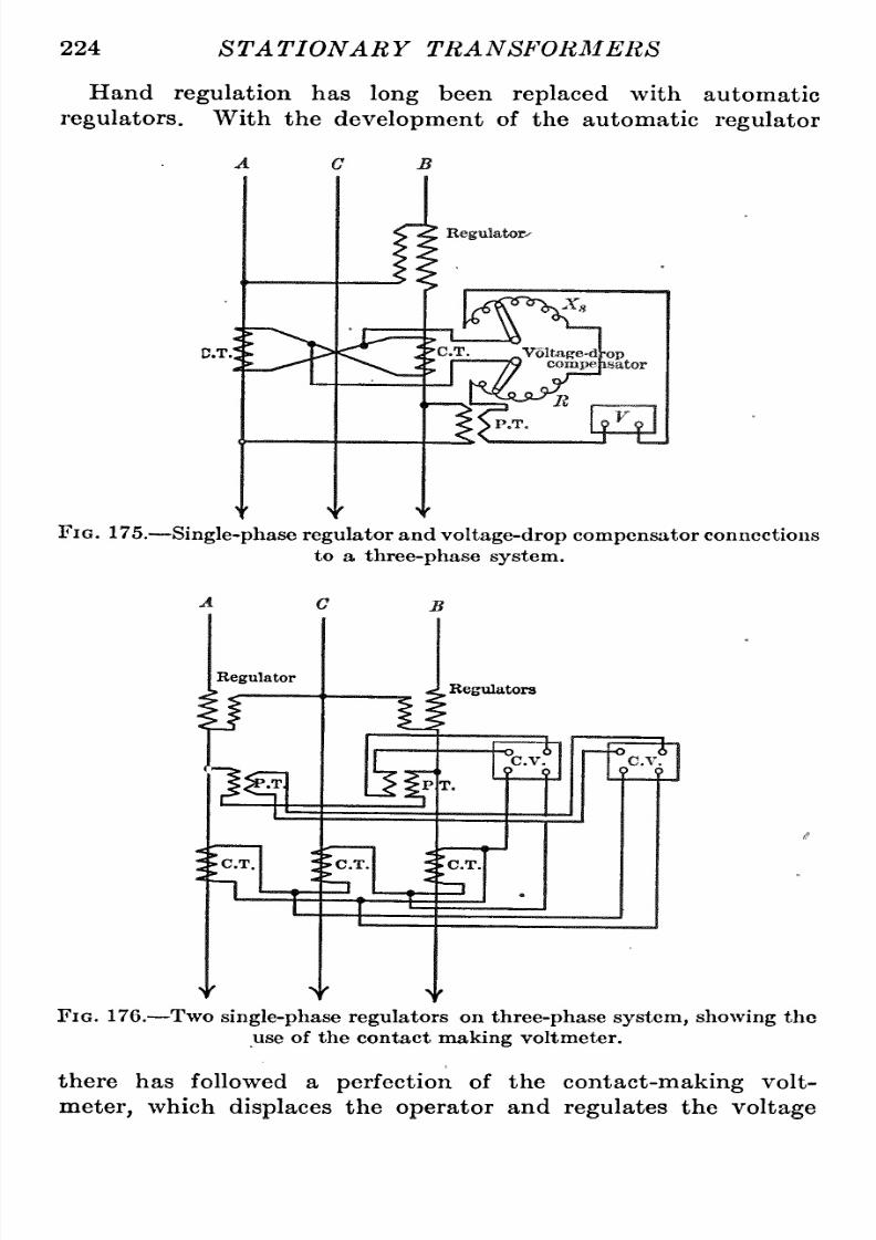
8/11/2019 Transformer Practice 1000194704
http://slidepdf.com/reader/full/transformer-practice-1000194704 236/290
224
ST A
TIONAR
Y
TRANSFORMERS
Hand
regulation
has
long
been
replaced
with
automatic
regulators.
With
the
development
of
the
automatic
regulator
D.T.
Fig.
175.
Single-phase
regulator
and
voltage-drop
compensator
connections
to
a
three-phase
system.
Regulator
'1^
C.T.
Regulators
-o
o
C.V
9
?
T=f
y
Y
y
Fig.
176.
Two
single-phase
regulators
on
three-phase system,
showing
the
use
of
the
contact
making
voltmeter.
there
has followed
a
perfection
of
the
contact-making
volt-eter,
which
displaces
the
operator
and
regulates
the
voltage

8/11/2019 Transformer Practice 1000194704
http://slidepdf.com/reader/full/transformer-practice-1000194704 237/290
REGULATORS AND COMPENSATORS 225
automatically.
This
instrument is
composed
of
a
solenoid
with
two
windings;
a
shunt
winding
which
is
connected
in
parallel
with
the
secondary
of
a
potential
transformer,
and
a
series
winding
(differential
ith
respect
to
the
shunt
winding)
which is
connected
in series with
the
secondary
of the
series
transformer,
the
primary
of
which is in series
with
the feeder
circuit.
A
movable
core
passes
through
the
center
of
the
solenoid,
and
to
the
top
of this
core
is
attached
a
pivoted
lever.
The lever carries
at
its other
end
a
set
of
contacts
which
make
contact
with
an
upper
and
a
lower
stationary
contact.
The
lever
is
set
by
means
of
a
springactingagainst
the
core,
so
that
its
contacts
are
midway
between
the
upper
and
lower
stationary
contacts
when
normal
voltage
is
on
the shunt
coil
of the
meter.
The
stationary
ontacts
form,
when
closed,
a
circuit
to
one or
the other
of
two
coils
of
a
relay
switch,
which
in
turn
controls
a
motor
on
the
regulator
cover.
Any
deviation
of
voltage
from
normal
causes
contact to
be made
and
the
regulator
corrects
for
this
change,
bringing
the
voltage
back
to
normal.
When
compensating
for
line
drop
to
a
distant
point
the
current
coil
is
used
and
as
the
load
increases,
he
regulator
boosts the
voltage
by
the
proper
amount.
In
this
manner
the
meter
can
be
set
so
that
constant
voltage
can
be
maintained
at
a
great
distance
from the
regulator.
The
connections
of
this
instrument
for
a
feeder
circuit
where
lighting
is
connected
on
only
two
phases
of
a
three-phase
system
and
motors
connected
to the
same,
are
shown
in
Fig.
1
76.
Two sin-le-phas
regulators
and three
series
t{||hsf
rmers
(one
transformer
in
each
conductor)
are
necessary.
If
the
series
transformer
in
the
middle
conductor
or
phase
were
not
installed,
roper
com-ensation
could
not
be
secured,
owing
to both
phase
displace-ent
and
an
unbalancing
of
current
in
the
three
phases.
Three
single-phase
regulators
are
usually employed
when
lighting
and
power
are
taken
from all
the
three
phases
of
a
three-phase
system.
One
three-phaseregulator
may
be
used,
in
which
case
it
is better
to
employ only
two
series
transformers
cross-connected,
so
as
to
get
an
average
of
unbalanced
current.
With
single-phase
egulators
s
shown
in
Fig.
177 each
phase
can
be
adjusted
independently
of
the others and
constant
voltage
established
at
the
load
center
of
each.
For
this
reason
it is
better
to
use
three
single-phase
egulators
n
preference
to
one
three-
phase
regulator.
15

8/11/2019 Transformer Practice 1000194704
http://slidepdf.com/reader/full/transformer-practice-1000194704 238/290
226
ST
A
TIONAR
Y
TRANSFORMERS
For
three-phase
four-wire
systems,
three
single-phase
regula-ors
are
employed having
their secondaries
connected
in
series
with
a
phase
conductor
and
their
primaries
excited
from
phase
conductors
to neutral.
This
method
is
equivalent
to
three
independent
single-phase
circuits.
if
y
y
Fig. 177.
An
installation
giving perfect regulation
when
properly
installed
and
operated.
%

8/11/2019 Transformer Practice 1000194704
http://slidepdf.com/reader/full/transformer-practice-1000194704 239/290
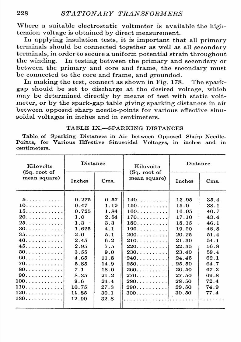
8/11/2019 Transformer Practice 1000194704
http://slidepdf.com/reader/full/transformer-practice-1000194704 240/290
228
STATIONARY
TRANSFORMERS
Where
a
suitable
electrostatic
voltmeter
is
available
the
high-
tension
voltage
is
obtained
by
direct
measurement.
In
applying
insulation
tests,
it is
important
that
all
primary
terminals
should
be
connected
together
as
well
as
all
secondary
terminals,
n
order
to
secure
a
uniform
potential
strain
throughout
the
winding.
In
testing
between the
primary
and
secondary
or
between
the
primary
and
core
and
frame,
the
secondary
must
be
connected
to
the
core
and
frame,
and
grounded.
In
making
the
test,
connect
as
shown
in
Fig.
178.
The
spark-
gap
should
be
set to
discharge
at
the
desired
voltage,
which
may
be
determined
directly
by
means
of
test
with
static
volt-eter,
or
by
the
spark-gap
table
giving
sparking
distances in air
between
opposed
sharp
needle-points
for
various effective
sinu-oidal
voltages
in inches and
in centimeters.
TABLE
IX.
SPARKING
DISTANCES
Table of
Sparking
Distances in Air
between
Opposed Sharp
Needle-
Points,
for Various
Effective Sinusoidal
Voltages,
in inches and
in
centimeters.
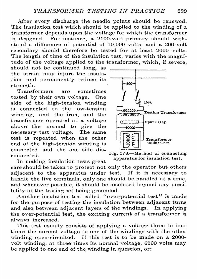
8/11/2019 Transformer Practice 1000194704
http://slidepdf.com/reader/full/transformer-practice-1000194704 241/290
TRANSFORMER
TESTING
IN PRACTICE
229
Testing
Transformer
After
every
discharge
the needle
points
should
be
renewed.
The
insulation
test
which
should be
applied
to
the
winding
of
a
transformer
depends
upon
the
voltage
for
which
the
transformer
is
designed.
For
instance,
a
2100-volt
primary
should
with-tand
a
difference
of
potential
of
10,000
volts,
and
a
200-volt
secondary
should therefore be tested for
at
least 2000
volts.
The
length
of
time
of
the
insulation
test,
varies
with
the
magni-ude
of
the
voltage
applied
to
the
transformer, which,
if
severe,
should
not
be
continued
long,
as
the
strain
may
injure
the
insula-ion
and
permanently
reduce its
strength.
Transformers
are
sometimes
tested
by
their
own
voltage.
One
side
of
the
high-tension
winding
is
connected
to
the
low-tension
winding,
and the
iron,
and
the
transformer
operated
at
a
voltage
above the normal
to
give
the
necessary
test
voltage.
The
same
test
is
repeated
when the other
end
of
the
high-tensionwinding
is
connected
and
the
one
side dis-onnected.
In
making
insulation
tests
great
care
should
be taken
to
protect
not
only
the
operator
but others
adjacent
to
the
apparatus
under
test.
If
it is
necessary
to
handle
the
live
terminals,only
one
should
be
handled
at
a
time,
and whenever
possible,
t
should
be
insulated
beyond
any
possi-ility
of
the
testing
set
being grounded.
Another insulation
test
called
over-potential
test is made
for the
purpose
of
testing
the
insulation
between
adjacent
turns
and also between
adjacent
layers
of
the
windings.
In
applying
the
over-potential
test,
the
exciting
current
of
a
transformer
is
always
increased.
This
test
usually
consists
of
applying
a
voltage
three
to
four
times
the
normal
voltage
to
one
of
the
windings
with
the
other
winding
open-circuited.
If
this
test
is
to
be made
on a
2000-
volt
winding,
at
three
times its
normal
voltage,
6000
volts
may
be
applied
to
one
end
of
the
winding
in
question,
r:
Fig.
178.
Method of
connecting
apparatus
for insulation
test.
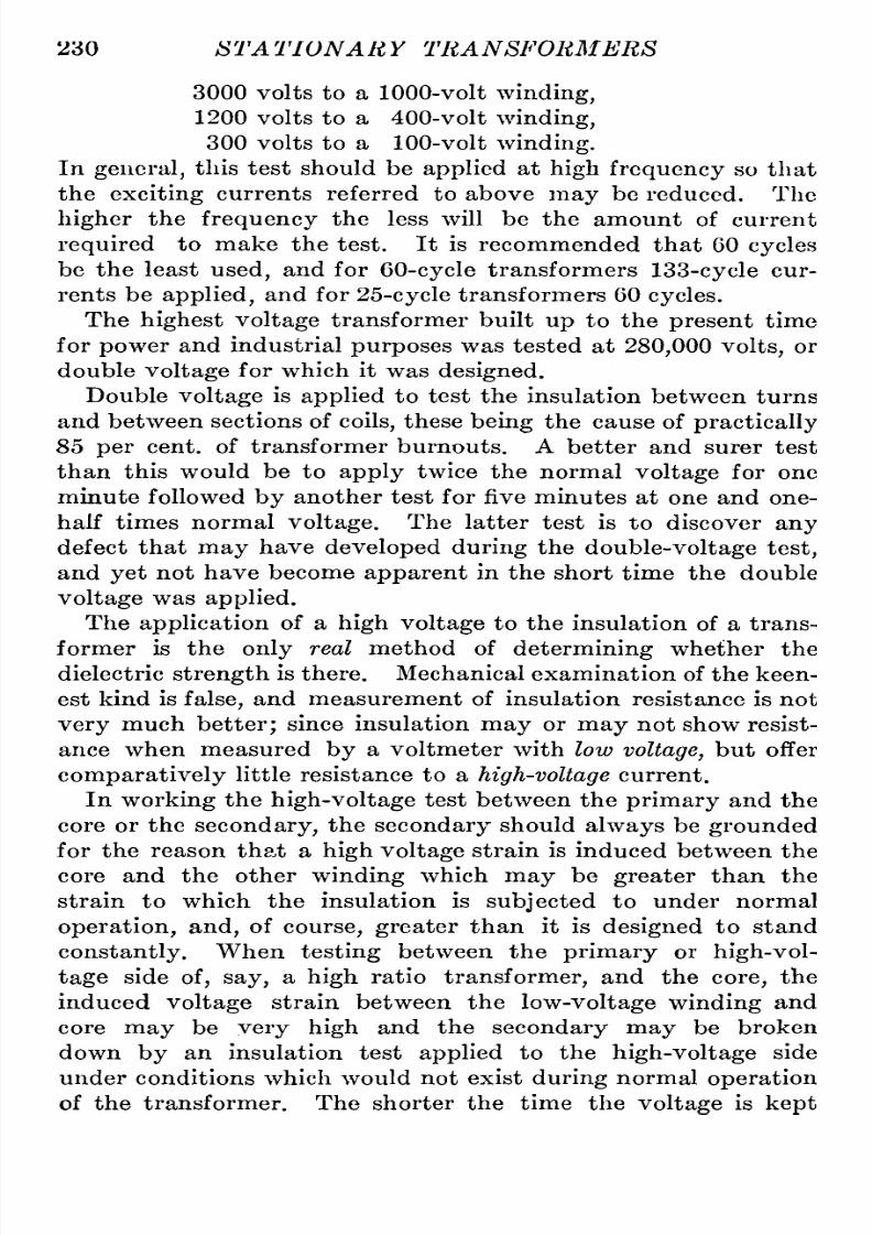
8/11/2019 Transformer Practice 1000194704
http://slidepdf.com/reader/full/transformer-practice-1000194704 242/290
230
STATIONARY
TRANSFORMERS
3000
volts
to
a
1000-volt
winding,
1200
volts
to
a
400-volt
winding,
300
volts
to
a
100-volt
winding.
In
general,
this test
should
be
applied
at
high
frequency
so
that
the
exciting
currents
referred
to
above
may
be
reduced.
The
higher
the
frequency
the
less
will
be the
amount
of
current
required
to
make the
test.
It
is
recommended
that
60
cycles
be
the least
used,
and
for
60-cycle
transformers
133-cycle
cur-ents
be
applied,
and for
25-cycle
transformers
60
cycles.
The
highest
voltage
transformer
built
up
to
the
present
time
for
power
and
industrial
purposes
was
tested
at
280,000 volts,
or
double
voltage
for
which
it
was
designed.
Double
voltage
is
applied
to test
the
insulation
between
turns
and
between
sections
of
coils,
hese
being
the
cause
of
practically
85
per
cent,
of transformer
burnouts.
A
better
and
surer
test
than
this
would
be
to
apply
twice the normal
voltage
for
one
minute
followed
by
another
test
for
five minutes
at
one
and
one-
half times normal
voltage.
The latter
test
is
to
discover
any
defect
that
may
have
developed
during
the
double-voltage
test,
and
yet
not
have become
apparent
in
the
short
time the
double
voltage
was
applied.
The
application
of
a
high
voltage
to
the
insulation
of
a
trans-ormer
is
the
only
real method of
determining
whether
the
dielectric
strength
is
there.
Mechanical
examination
of the keen-st
kind is
false,
and
measurement
of
insulation resistance is
not
very
much
better;
since insulation
may
or
may
not
show
resist-nce
when measured
by
a
voltmeter
with
low
voltage,
but
offer
comparatively
littleresistance
to
a
high-voltage
urrent.
In
working
the
high-voltage
test
between
the
primary
and
the
core or
the
secondary,
the
secondary
should
always
be
grounded
for the
reason
that
a
high
voltage
strain
is induced
between the
core
and the other
winding
which
may
be
greater
than the
strain
to
which
the
insulation is
subjected
to
under
normal
operation,
and,
of
course,
greater
than
it is
designed
to
stand
constantly.
When
testing
between the
primary
or
high-vol-age
side
of,
say,
a
high
ratio
transformer,
and
the
core,
the
induced
voltage
strain between the
low-voltage
winding
and
core
may
be
very
high
and
the
secondary
may
be
broken
down
by
an
insulation
test
applied
to
the
high-voltage
side
under
conditions which
would
not
exist
during
normal
operation
of
the
transformer.
The
shorter
the
time
the
voltage
is
kept
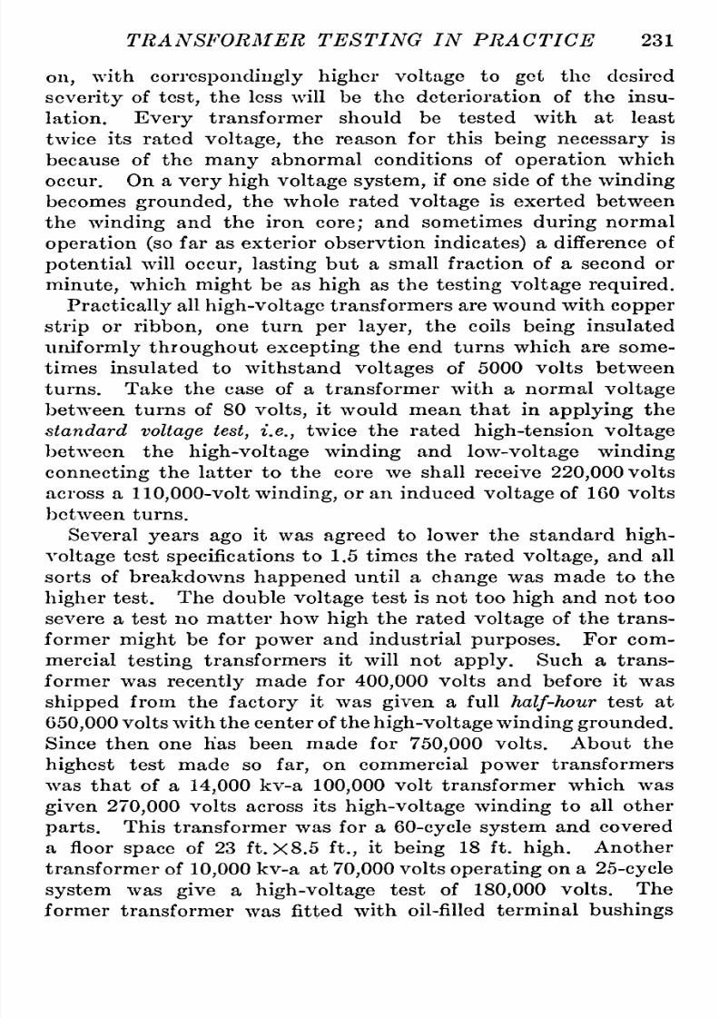
8/11/2019 Transformer Practice 1000194704
http://slidepdf.com/reader/full/transformer-practice-1000194704 243/290
TRANSFORMER
TESTING IN
PRACTICE
231
on,
with
correspondingly
higher
voltage
to
get
the
desired
severity
of
test,
the
less
will be
the deterioration
of
the
insu-ation.
Every
transformer
should be
tested
with
at
least
twice
its
rated
voltage,
the
reason
for this
being
necessary
is
because
of
the
many
abnormal
conditions
of
operation
which
occur.
On
a
very
high
voltage
system,
if
one
side of
the
winding
becomes
grounded,
the
whole rated
voltage
is
exerted between
the
winding
and the
iron
core;
and
sometimes
during
normal
operation (so
far
as
exterior observtion
indicates)
difference
of
potential
will
occur,
lasting
but
a
small
fraction
of
a
second
or
minute,
which
might
be
as
high
as
the
testing
voltage
required.
Practically
ll
high-voltage
transformers
are
wound
with
copper
strip
or
ribbon,
one
turn
per
layer,
the
coils
being
insulated
uniformly
throughout
excepting
the
end
turns
which
are some-imes
insulated
to
withstand
voltages
of
5000
volts between
turns.
Take
the
case
of
a
transformer with
a
normal
voltage
between
turns
of
80
volts,
it
would
mean
that
in
applying
the
standard
voltage
test,
i.e.,
twice
the rated
high-tension
voltage
between
the
high-voltagewinding
and
low-voltage
winding
connecting
the
latter
to
the
core
we
shall
receive
220,000
volts
across
a
110,000-voltwinding,
or an
induced
voltage
of
160
volts
between
turns.
Several
years ago
it
was
agreed
to
lower the
standard
high-
voltage
test
specifications
o
1.5
times
the
rated
voltage,
and
all
sorts
of breakdowns
happened
until
a
change
was
made
to
the
higher
test.
The
double
voltage
test
is
not
too
high
and
not too
severe
a
test
no
matter
how
high
the
rated
voltage
of the
trans-ormer
might
be
for
power
and
industrial
purposes.
For
com-ercial
testing
transformers
it will
not
apply.
Such
a
trans-ormer
was
recently
made for
400,000
volts and
before
it
was
shipped
from
the
factory
it
was
given
a
full
half-hour
test at
650,000
volts
with
the
center
of the
high-voltagewinding grounded.
Since
then
one
has
been
made
for
750,000
volts.
About
the
highest
test
made
so
far,
on
commercial
power
transformers
was
that
of
a
14,000
kv-a
100,000
volt
transformer
which
was
given
270,000
volts
across
its
high-voltage
winding
to
all
other
parts.
This
transformer
was
for
a
60-cycle
system
and
covered
a
floor
space
of
23
ft.
X
8.5
ft,,
it
being
18
ft.
high.
Another
transformer
of
10,000
kv-a
at
70,000
volts
operating
on
a
25-cycle
system
was
give
a
high-voltage
test
of
180,000
volts.
The
former
transformer
was
fitted
with oil-filled
terminal
bushings

8/11/2019 Transformer Practice 1000194704
http://slidepdf.com/reader/full/transformer-practice-1000194704 244/290
232
STATIONARY
TRANSFORMERS
and
during
the
test
of these
bushings
at
270,000
volts,
no corona
was
visible
even
when
in
utter
darkness.
The
latter
trans-ormer
was
fitted
with
the condenser
type
of
terminal
bushings
which is made
up
of
alternate
layers
of
insulating
nd
conducting
material.
In
the
operation
of
transformers
it
has been found
that
we
are
confronted
with
the
difficult
problem
of
taking
care
of
the
voltage
rise between
turns
that
may
not
increase the
line
voltage
suf-icient
to
be noticeable
but be
so
high
in
the transformer
itself
and
only
effective
across a
few
turns
as
to
short-circuit
and
burn-out
that
part
where the
excessive
voltage
is
concentrated.
In fact
it is
quitepossible
to
get
100
times
normal
voltage
across
a
small
percentage
of the
total
turns
and
at
the
same
time
have
no
appreciable
increase in
voltage
at
the
terminals
of the
tra,nsformer.
With
or
without
extra
insulation
on
the
end
turns
of
trans-ormers
operating
on
high-voltage
systems,
the
voltage
difference
on
the end
turns
due
to
switching,
etc.,
is
there,
and the
only
way
out
of
the
difficulty
s
to
provide
sufficient
insulation
to
make
it
safe
irrespective
f the
external choke
coils
which
are
always
provided.
This
double
voltage
test
is
made after
the
transformer
has
been
thoroughly
dried
out
and
the
quality
of
oil
brought
up
to
standard.
In the
past
some
makers
placed
too
much
reliance
on
oil
as an
insulator
and
consequently
left
out
much
solid insula-ion;
the
result
was
that
many
burnouts
occurred,
because
the
oil
could
not
be
relied
upon
always,
its
insulating
proportions
decreasing
with
age.
In
many
cases
burnouts
occurred
immedi-tely
the
transformers
were
put
into service
after the
drying-out
process
had
been
completed,
and the
voltage
slowly brought
up
to
the
desired
value.
Temperature.
The
temperature
or
heat
test
of
a
transformer
may
be
applied
in
several
ways,
all of
which'
are
arranged
to
determine
as
nearly
as
possible
the
working
temperature
condi-ions
of
the
transformer
in
actual
service.
Before
starting
a
temperature test,
transformers should
be
left
in
the
room
a
sufficient
length
of
time
for
them
to
be
affected
alike
by
the
room
temperature.
If
a
transformer
has
remained
many
hours
in
a
room
at
con-tant
temperature
so
that it
has reached
approximately
uniform
temperature
throughout,
the
temperature
of
the surface
may

8/11/2019 Transformer Practice 1000194704
http://slidepdf.com/reader/full/transformer-practice-1000194704 245/290
TRANSFORMER
TESTING
IN
PRACTICE
233
be
taken
to
be
that
of
the
interior,
r
internal
temperature. If,
however,
the
transformer is
radiating
heat
to
the
room,
the
temperature
of
the
surface
will
be
found
to
give
littleindication
of
the
temperature
of
the
interior.
To
ascertain
the
temperature
rise
of
a
transformer,
thermom-ters
are
sometimes
used,
which
give
only
comparative
results
in
temperature
and
such
measurements
are,
therefore,
seful
only
in
ascertaining
an
increase in
temperature
during
the heat
run.
If thermometers
are
used
they
should
be screened from
local
air-
currents
and
placed
so
that
they
can
be read
without
being
removed. If
it is desired
to
obtain
temperature
curves,
ther-ometer
readings
should
be taken
at
half-hour
intervals
through-ut
the
test
and until the
difference
between
the
room
temper-ture
and
that
of the
transformer under
test
is
constant.
In order
to
determine
temperature
rise
by
measurement
of
resistance,
t
is
necessary
to
determine
first
what
is
called
cold
resistance
by
thermometer
measurements
after
the
trans-ormer
has
remained in
a room
of
constant
temperature
for
a
sufficient
length
of
time
to
reach
a
uniform
temperature
through-ut
its
windings.
The
temperature
rise
by
resistance
gives
the
average
rise
throughout
the
windings
of
the
transformer,
and
to
obtain
average
temperature
rise
of
each
of
the
windings, separate
resistance
readings
should
be
taken
of
each.
The
temperature
rise
by
means
of
resistance
may be
deter-ined
by
the
use
of
the
followingequation:
R
=
Ro(l
+0.0040;
(31)
or
by
equation
Resistance
at
S C
=
~^^^~R'
(32)
where
R'
is
the resistance
at
any
temperature
t.
where
R^
is
the
resistance
at
room
temperature;
R
the
resistance
when
heated,
and
t
the
rise in
temperature.
The
temperature
coefficient
of resistance is taken
at
0.004
as
25 C.
Considering
the above
equation,
the
temperature
rise
corrected
to
25
C.
may
be
determined in
the
following
manner.
Example:
Let
room
temperature
be
20
C,
and
absolute
temperature
of transformer
60 C.
Ascertain
correct
tem-erature
rise.

8/11/2019 Transformer Practice 1000194704
http://slidepdf.com/reader/full/transformer-practice-1000194704 246/290
234
STATIONARY
TRANSFORMERS
The
temperature
is
apparently
60
20
=
40
C,
but since
the
room
temperature
is
5 lower than the
standard
requirements,
a
correction
of
0.5X5
=
2.5
per
cent, must
be
added
giving
a
corrected
temperature
of
100X2.5X40
100
= 41 C.
pic
Thus
with
a room
temperature
of
20
C.
the
rise in
temperature
calculated
from the above
equation
should
be
added
by
2.5
per
cent.,
or
with
a room
temperature
of
35
C,
the
rise
in
temper-ture
should be decreased
by
5
per
cent.;
and with
a room
temperature
of 15
C,
the
rise
in
temperature
should
be
increased
by
5
per
cent.,
and
so on.
If
the
room
temperature
differs
from 25
C.
the
observed rise
in
temperature
should be
corrected
by
0.5
for
each
degree
centigrade.
This
correction
is
intended
to
com-ensate
for
the
change
in
the
radia-ion
constant
as
well
as
for
the
error
involved in
the
assumption
that the
temperature
coefficient
is
0.004,
or more
correctly,
0.0039,
remains
constant
with
varying
room
temperatures.
To
measure
the
increase
of
re-istance
let
us
take the
follow-ng
example.
The
primary
resis-ance
of
a
certain
transformer
is
8
ohms,
and
at
its
maximum
operating
temperature,
9 ohms.
Temperature
of
room
during
test
is
30
C.
Ascertain
cor-ected
temperature
rise.
The
primary
resistance
taken
at
a
temperature
of
30
C,
when
referred to
temperature
coefficient
of
0.4
per
cent,
per
2000
Sinn
100-
Umj jImJ UjiMWHL
m
-3000-
-4000-
mmmm
Fig.
179.
Method of
con-ecting
transformers
and instru-ent
for
an over-potential
test
For
water-cooled
transformers,
the
standard
temperature
of reference
for
incoming
cooling
water
should be 25
C,
measured
at
thfe intake of the transformer. In
testing
water-cooled
transformers it is
important
to
maintain the
temperature
of
the
ingoing
water
within 5 C.
of the
surrounding air,
but
where
this is
impracticable,
the reference
ambient
temperature
should be
taken
as
that
indicated
by
the
resistance
of the
windings,
when
the disconnected
transformer
is
being supplied
with the
normal
amount
of
cooling
water
and
the
temperature
of
the
windings
has become
constant.

8/11/2019 Transformer Practice 1000194704
http://slidepdf.com/reader/full/transformer-practice-1000194704 247/290

8/11/2019 Transformer Practice 1000194704
http://slidepdf.com/reader/full/transformer-practice-1000194704 248/290
236
STATIONARY TRANSFORMERS
in
the
oil,
on
the
cores,
tank
and
various
other
parts
of
the
transformer
when
possible,
A method
of
heat-run used
to
some
extent,
and known
as
the
^'Opposition
test,
is
shown
in
Fig.
180.
In
this
test
two trans-ormers
of
the
same
capacity,
voltage
and
frequency
are
required
and
connected
as
shown
in
diagram.
The
two
secondary
wind-ngs
are
connected
in
parallel,
and the
two
primary
windings
connected
in
series
in
such
a
way
as
to
oppose
each
other.
The
two
secondary
leads receive
exciting
current
at
the
proper
voltage
and
frequency,
while
the
primary
leads receive
a
current
equal
to
the
desired
load
current
;
the
wattmeter
in
the
primary
circuit
PEl L.
F31
Fig.
180.
Method
of
connecting
apparatus
for
heat
test,
known
as
oppo-ition
test.
measures
the
total
copper
loss,
and
that
in the
secondary
the
total
core
loss.
Another
method often
used
and called the
motor
generator
test is
shown
in
Fig.
181. In
this
test two
transformers
are
used,
having
their
high-tension
windings
connected
together.
Proper
voltage
is
applied
to
the
low-tension
winding
of
one
of
the
transformers,
and
the
low-tension
winding
of
the
other
trans-ormer
is
connected
to
the
same source.
Then with the switch
s
open,
the
wattmeter
reads
the
core
losses of
both
transformers,
and
with
s
closed,
it
reads
the total loss.
Subtracting
the
core
loss
from
the
total,
the
copper
loss is
obtained.
This
method
requires
(as
is
also the
case
in
the
opposition
test)
that
only
the
losses be
supplied
from the
outside.

8/11/2019 Transformer Practice 1000194704
http://slidepdf.com/reader/full/transformer-practice-1000194704 249/290
TRANSFORMER TESTING IN
PRACTICE
237
At
the
present
time
the
flow
point
of
the
impregnating
com-ounds
gives
a
temperature
limit
of about
90
C.
It
is
possible
that
the
development
of
synthetic
gums
will
soon
reach
a
stage
to
permit
of actual
operating
temperatures
of
at
least
125
to
150
C.
The
only difficulty
ith such
an
operating
temperature
will
be
with
the
oil.
Certain
practices
of
drying
out
transformers
are
applicable
to
temperature
tests
(see
Chapter
IX).
In
drying
out
trans-ormers
it is
always
more
convenient
to
short-circuit
the
low-
voltage
winding
and
impress
sufficient
voltage
on
the
high-
FiG. 181.
Another
method
of
connecting
apparatus
for heat
test known
as
motor
generator
test.
voltage
winding
to
cause
about
20 to 30
per
cent,
current
to
flow
through
the
transformer
coils.
This
current
is
found
quite
suffi-ient
to
raise
the
temperature
of the
coils
to
the
desired
limit.
To
make
normal
current
flow
through
the
windings
when the
secondary
is
short-circuited
requires
a
voltage
of
about
3,3
per
cent,
of
the
high
voltage
winding,
according
to
the
way
the
wind-ngs
are
connected
(series
or
parallel).
For
example:
It is
desired
to
dry
out
a
100,000
volt,
10,000
kw.
single-phase
rans-ormer;
a
5000
kw.,
a
2500
kw.,
and
a
1250
kw.
of the
same
voltage,
etc.
What
will
be the
voltage
necessary
to
circulate
20
and
30
per
cent,
of
noiynal
current
through
the
coils
of the
transformers?
The
answer
to
this is
best
given
in
the
following
table
:

8/11/2019 Transformer Practice 1000194704
http://slidepdf.com/reader/full/transformer-practice-1000194704 250/290
238
ST A
TIONA
R
Y TRA NSFORMERS
TABLE XI
Conditions
of
test
Capacity
of
transformers in
kw.
1250
Normal
high-voltage
current at
100,-
000
volts
on
full-load.
Voltage required
to circulate
same
when
low-voltage
winding
is
short-
circuited.
At 20
per
cent,
normal
current.
. . .
Voltage
required
for
20
per
cent.
.
.
At
30
per
cent,
normal
current
Voltage
required
for
30
per
cent.
. .
12.5
amp.
3300
volts
2.5
amp.
660
volts
3.75
amp.
990
volts
If
one
is
obliged by
circumstances
to
short-circuit the
high-
voltage
winding,
the
same
per
cent,
voltage
holds
good.
As-uming
the low
voltage
to
be
5000
volts,
it
will
require
33
volts
for
20
per
cent,
normal
current,
and
50
volts
for
30
per
cent,
normal
current.
With
the
high-voltagewinding
connected
for
50,000
volts,
the
current
values
given
above
will
be
doubled
but
the
temperature
conditions will remain
about
the
same.
The
maximum
values of
temperature
for
large
transformers
is
a
rise
of
40
C.
under
rated
load,
this
value
having
for
its
basis
a
room
temperature
of 25
C,
For
rated
overloads
the
limiting
temperature
rise is
55
C.
In
an
earlier
part
it
has
been
stated
that,
in
general,
it is
found that
transformers
will
operate
quite
,satisfactorily
hen worked
at
their
limiting
temperatures;
that
is
to
say,
around that
point
where
the
best
efficiency
nd
full-load
is
obtained.
A
condition
of
this kind
might
mean
that for short
periods
of
time
an
overload
is
required,
hence
a
high
ratio
of
copper
and
iron
loss,
and decreased
first
cost
of
transformers.
High
temperatures
are
objectionable
in
transformers.
Their
effect
on
the
insulation
at
temperatures
about
100
C.
means
gradual
deterioration;
heir
effect
on
the
copper
loss
is
a
decided
objection,
this
loss
increasing
about
10
per
cent,
with
an
increase
of 25
C.
in
the
temperature;
their
effect
on
the
oil is
to
increase
the
deposition
of
hydrocarbon
on
the
windings
and internal
cooling
apparatus,
and
a
further bad
effect
is their
tendency
to

8/11/2019 Transformer Practice 1000194704
http://slidepdf.com/reader/full/transformer-practice-1000194704 251/290
TRANSFORMER
TESTING
IN PRACTICE
239
increase
the
aging
of the
iron
(not including
the
present
improved
silicon
steel).
To
get at,
and
measure,
the
maximum
temperature
affect-ng
the insulation is
almost
impossible
and
only
the
average
temperature
is
measured
during
a
regulartest,
the
temperature
being
taken
at
the
top
of the
oil
and
not at
the
immediate
surface
of contact
with
the
coils
or core
of
the
transformer.
The
Standardization
Rules
of the
A.I.E.E.
state
that the
rise
in
temperature
of
a
transformer
should
be
based
on
the
temperature
of the
surrounding
air.
The
cooling
medium
for
oil-insulated
self-cooled and
for
forced-air
cooled
transformers
is
the
surrounding
air,
but
for oil-insulated
water-cooled
trans-ormers
the
cooling
medium
is
water,
and the
temperature
rise
to
be
considered
in
this
type
is
that
of the
ingoing
water
and
not
the
temperature
of the
surrounding
air.
On
this basis
a
transformer
of
this
type
will
be
about
10
C.
less
than
one
specified
n
the basis of
the
temperature
of
the
surrounding
air.
The class of oil used
for
insulating
purposes has
a
great
effect
on
the
temperature.
An
increase
in
the
viscosity
of
the
oil
means
an
increase
in
the
frictional
resistance
to
its
flowing.
The
velocity
of
circulation is
reduced, thereby causing
an
in-reased
rise in
the
temperature.
As
yet
it
has
not
been
possible
to
formulate
a
correct
theory
of
the
laws
of
cooling
for
general
cases
which
will indicate
once
for all that
combination
of
conditions which is
most
favor-ble
to
cooling,
and
enable
one
to
say
with
considerable
accuracy
not
only
what
will
be
the
average
temperature
rise in
any
given
case,
but also what
will
be
the
maximum
rise.
Ratio of Transformation.
The
ratio
of
a
transformer
is
tested
when
the
regulation
test
is
made.
It
is
the
numerical
relation
between
the
primary
and
secondary voltage.
The ratio
of
a
trans-ormer
must
be
correct,
otherwise
the
service will
be
unsatisfac-ory,
because the
secondary voltage
will
be
too
high
or
too
low.
For successful
parallel
operation,
correct
ratios
are
essential;
otherwise
cross-currents
will
be
established
through
the
windings.
A
method
of
ratio
test
is
shown
in
Fig.
182,
where the
primary
of
the
transformer
under
test
is in
parallel
with
the
primary
of
the
standard
ratio
transformer,
and
the
two
secondary
wind-ngs
are
connected
in
series^
Standard
transformer
ratios
are usually
an
exact
multiple
of
5
or
10.

8/11/2019 Transformer Practice 1000194704
http://slidepdf.com/reader/full/transformer-practice-1000194704 252/290
240
STATIONARY
TRANSFORMERS
TABLE
XII.
TABLE
OF
TEMPERATURE
COEFFICIENTS
OF
RESISTIVITY
IN
COPPER
AT
DIFFERENT INITIAL
TEMPERATURES CENTIGRADE
Initial
temperature
cent.
Temp,
coefficient
in
per
cent,
per
degree
cent.
Initial
temperature
cent.
Temp,
coefficient
in
per
cent,
per
degree
cent.
0
0.4200
1
0.4182
25
0.3801
26 0.3786
27 0.3772
Low-voltage
distribution
transformer ratios
are
(low-voltage
windings)
110,
220,
440
or
550
volt
to
(primary
voltage
wind-ng)
1,110/2,200,
3,300,
6,600
and
10,000
volts.
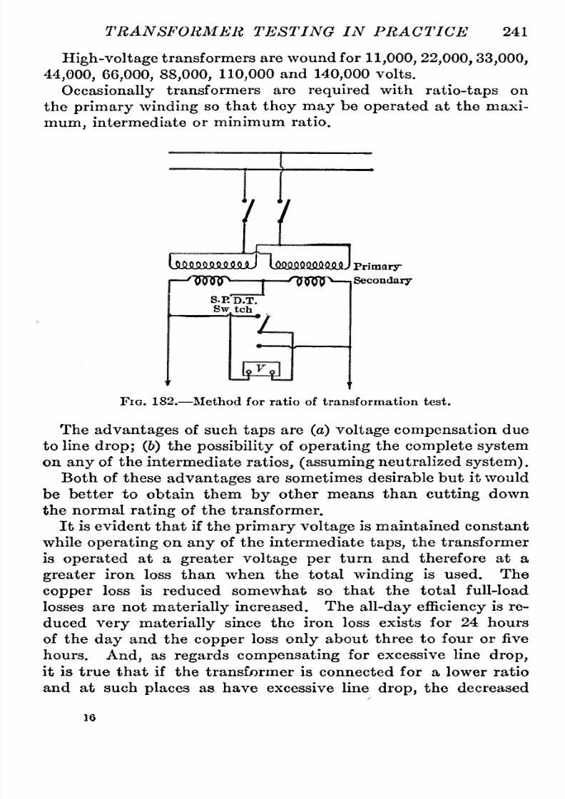
8/11/2019 Transformer Practice 1000194704
http://slidepdf.com/reader/full/transformer-practice-1000194704 253/290
TRANSFORMER
TESTING
IN
PRACTICE
241
High-voltage
transformers
are
wound for
11,000,
22,000,33,000,
44,000,
66,000,
88,000,
110,000
and
140,000
volts.
Occasionally
transformers
are
required
with
ratio-taps
on
the
primary
winding
so
that
they
may
be
operated
at
the
maxi-um,
intermediate
or
minimum
ratio.
7 7
ImAMOAMmJ
lQfi.Q.0QQ.O.QO.Q.Qj
Primary
^DqOO^
I
^^^'^
I
Secondary
S.E
D.T.
Sw
tch
Fig.
182.
Method
for
ratio
of
transformation
test.
The
advantages
of such
taps
are
(a)
voltage
compensation
due
to
line
drop;
(6)
the
possibility
f
operating
the
complete
system
on
any
of the
intermediate
ratios,
(assuming
neutralized
system).
Both of
these
advantages
are
sometimes
desirable
but
it
would
be better
to
obtain
them
by
other
means
than
cutting
down
the
normal
rating
of the
transformer.
It
isevident
that if
the
primary
voltage
is
maintained
constant
while
operating
n
any
of
the intermediate
taps,
the transformer
is
operated
at
a
greater
voltage
per
turn
and
therefore
at
a
greater
iron
loss than
when
the
total
winding
is
used.
The
copper
loss
is
reduced somewhat
so
that the
total full-load
losses
are
not
materially
increased.
The
all-day
efficiency
s
re-uced
very
materially
since
the
iron
loss
exists
for
24
hours
of the
day
and the
copper
loss
only
about
three
to
four
or
five
hours.
And,
as
regards
compensating
for
excessive line
drop,
it is
true
that
if
the transformer is connected for
a
lower ratio
and
at
such
places
as
have excessive line
drop,
the
decreased
16

8/11/2019 Transformer Practice 1000194704
http://slidepdf.com/reader/full/transformer-practice-1000194704 254/290
242
STATIONARY
TRANSFORMERS
primary
voltage
impressed
upon
the
decreased
primary
turns
will
produce
approximately
normal
core
loss
and
the
desired
secondary
voltage
during
the
period
of
full-load
on
the
system.
However, during
light
load,
when
a
heavy
current
is
no
longer
in the
primary
and
an
excessive
drop
no
longer
exists,
the
transformer
connected
and
operating on
any
of
the
intermediate
or
lower
ratio
taps
will be
subjected
to
full
primary
voltage
impressed
on
the
reduced
primary
turns,
and
the
core
loss
of
the
transformer
will
become
ex-essive
and
the
secondary
voltage
in-reased
to
a
dangerous limit,
that
is
to
say,
dangerous
so
far
as
burn-outs
of
incandescent
lamps
are
concerned, for,
whoever
should
happen
to
turn
on
their
lamps during
the
period
of
light-load
operation,
is
sure
to
suffer from
exces-ive
lamp
burn-outs.
Operation
at
10.
per cent, above normal
voltage
for
which
the
lamp
is
designed,
reduces
its
life
to
-n
100
T.^
X
r
15
per
cent,
of its
normal
value.
Conse-
FiG.
183.
Effect
of
con-
^,1
.
.
necting
two
transformers
of
q^ently
by
operatmg
a
transformer
on
different
ratios in
parallel,
its
intermediate
ratio-taps,
offers the
disadvantage
of
excessive
core
loss
for
at
least
20
to
21
hours
in
the
day,
and
excessive
burning
out
of
lamps during
the
same
period
of
time.
Decreasing
the
ratio
of
a
transformer
from,
say,
10-1
to
9-1
and
maintaining
the
voltage
constant,
increase
the
core
loss
ap-roximate
20
per
cent.
A
difference
of about
10
per
cent,
in ratios
of
primary
and
sec-ndary
voltages
will
result
in
a
circulation
of about
100
per
cent,
full-load
current.
And
a
difference
of
2
per
cent,
in
the
ratios
may
result
in
a
circulation
of
20
per
cent,
full-load
current,
or a
1
per
cent,
difference in
ratio
may
result
in
a
10
per
cent,
circula-ion
of full-load
current;
thus
showing
the
absolute
necessity
for
having
the
ratios
always
exactly
the
same.
For
example;
take
Fig.
183
and
assume
that the
percentage
impedance
volts
of each
transformer
is
5
per
cent.,
and the measured
difference
between
points a
and
h shows
21
volts.
What
will be
the
circulating
urrent
with
open
secondaries?
The
21
volts is
effective
in
circulating
urrent
through
the
trans-ormer
windings
against
the
impedance
of
the
transformers
the

8/11/2019 Transformer Practice 1000194704
http://slidepdf.com/reader/full/transformer-practice-1000194704 255/290

8/11/2019 Transformer Practice 1000194704
http://slidepdf.com/reader/full/transformer-practice-1000194704 256/290
244 ST A
TIONARY
TRANSFORMERS
if
two
single-phase
transformers,
both
of
positive
polarity
or
both
of
negative
polarity,
re
to
be
operated
in
parallel,
hey
should
be
connected
together
as
shown.
If
all
traiisformers
are
alike,
they
may
have
the
same
polarity,
ut
if
some are
of
different
designs
or are
made
by
different
manufacturers,
their
polarity
may
be
different.
Single-phase
polarity
is
very
easily
determined;
not
so
with
polyphase
transformers
since
both
phase
relation
and
rotation
Positive
Polarity
=
B
NOI
E-e
^E-
NO
2
I
Negative
VJ
Polarity
E-e
abba
Fig.
185.
^Positive and
negative
polarity
of
single-phase
ransformers.
must
be
considered;
n fact
polyphase polarity
ay
mean
a
large
number of
possible
combinations.
Considering
first,
the
test
for
polarity
of
single-phase
rans-ormers,
it
is
best
to
consider
the
direction
of
voltages
to
know
whether
they
are
in
phase
or
in
opposition,
hat
is,
180
degrees
out
of
phase.
Positive
polarity
means
that
if,
during
the
test,
A-b
is
the
sum
of
voltage
A-B
and
a-h,
positivepolarity
is
ob-
'
i
'Noi
iryivn
ryyv-n
n
Fig.
186.
Method of
findingthreee-phase
polarity.
tained.
Negative
polarity
means
that
if,
the
voltage
between
A-b
is
the
value
of
secondary voltage
less
than
A-B and a-h
negative
polarity
is
obtained.
See
Fig.
185.
In
Fig.
185
we
have:
Positive
polarity
No.
1
transformer
={A
B)-\-(a h)=E- re.
and
Negative
polarity
No.
2
transformer
={A
B)
{a h)=E
e.

8/11/2019 Transformer Practice 1000194704
http://slidepdf.com/reader/full/transformer-practice-1000194704 257/290
TRANSFORMER
TESTING
IN PRACTICE
245
This
means
that,
in
order
to
connect No.
1
and
No.
2
in
parallel,
different
leads
must
be
connected
together.
A
A,
BB
on one
side
and
aa,
bb
on
the
other
side.
It
is
always better,
however,
when
a
positive
polarity
ransformer
is
to
be connected
in
parallel
ith
a
negative
polarity
transformer,
to
reverse
the
connections of
cither
the
high-voltagewinding
or
the
low-voltage
winding
of
one
of
the
transformers.
Fig.
186
shows the
method
of
finding
whether
two
three-phase
transformers have the
same
polarity.
In
making
the
above
test
similarly
located
terminals should
be
connected
together
as
shown.
If
no
voltage
is indicated between
leads
x'
and
x
or
between
y'
and
y,
the
polarities
re
the
same
and
the
connections
can
be made
and
if
desired,
put
into
regular
operation.
If,
however,
there is
a
difference
of
voltage
between
a
c
Fig. 187.
Testing
for
polarity
in
.three-phase
ystems.
y'
y
or
x'
x,
or
both,
the
polarity
of
the
two
groups
is
not
the
same
and
parallel
operation
is
impossible.
It
is
necessary
to
determine
the
polarity
f each
three-phase
transformer
separately.
The
correct
connections
under
these
circumstances,
re
given
in
Fig.
187.
Iron
or
Core Loss.
The
core
loss
includes
the
hysteretic
and
eddy-current
losses. The
eddy-current
loss
is
due to
currents
produced
in
the
laminations,
and
the
hysteretic
loss
is
due
to
molecular
friction.
The
core
loss
remains
practically
onstant
at
all
loads,
and
wUl
be the
same
whether
measured
from
the
primary
or
secondary
side,
the
exciting
current
in either
case
being
the
same
per
cent,
of
the full
load. The economical
opera-ion
of
a
lighting
plantdepends
in
a
largemeasure
on
the
selection
of
an
economical
transfornjer.
An
economical
transformer
is
seldom
the
one
of
lowest
first
cost,
nor
is it
necessarily
the
one
having
the
smallest
full-load losses.
It
is the
one
which has
the

8/11/2019 Transformer Practice 1000194704
http://slidepdf.com/reader/full/transformer-practice-1000194704 258/290
246
STATIONARY TRANSFORMERS
most
suitable
division
of
losses
for
the
service
for
which
it is
to
be
used.
The
hysteresis
oss
is
dependent
on
the iron
used,
and
in
a
given
transformer
varies in
magnitude
with
the
1.6
power
of the
(induction)
or
magnetic
density.
An
increase in
voltage applied
to
a
transformer
causes
an
increase
in
core
loss
(see following
table),
while
an
increase
in
the
frequency
results
in
a
corre-ponding
decrease
in
core
loss
the
density
varying
directly
as
the
voltage
and
inversely
as
the
frequency.
The
eddy
current
loss
varies
in
magnitude
with
the
conductivity
of
the
iron
and
the
thickness
of
laminations.
Both the
hysteresis
and
eddy
current
losses
decrease
slightly
s
the
temperature
of
the
iron
increases,
and
if
the
temperature
be
increased
sufficiently
he
hysteresis
oss
might
disappear
entirely
while
the
eddy
current
loss
will
show
a
decrease
with
increased
resistance
of
the
iron
due
to
this
temperature.
Thus
at
full-load,
or
in
other
words,
an
increase
in
temperature
to
the
limiting
temperature
rise
of
40
C.
may
cause
a
decrease
in
core
loss
of
about
5
per
cent,
depending
on
the
wave
form
of the
impressed
voltage.
For
ordinary
steel
used
in
transformers,
a
given
core
loss
at
60
cycles
may
consist
of
72
per
cent,
hysteresis
nd
28
per
cent,
eddy
current
loss,
the
hysteresis
loss
decreasing
with increased
frequency
while
tlie
eddy
current
loss
is increased with increased
frequency.
Low
power
factor of
exciting
current
is
not
in itself
very
objectionable.
This
can
best be
explained
by
taking
two trans-ormers,
one
made
up
of
ordinary
iron
and the other of modern
silicon
steel
or
alley-steel,
Take,
for
example,
two
5kw,
transformers.
The
one
made
up
of
ordinary
iron will have
a core
loss
of about
64
watts
while
that made of
silicon
steel
will
have
a
core
loss of
only
45
watts;
and,
taking
the
exciting
current
of
both
to
be
2
per
cent,
of
the
full-load
current,
we
have
the
follow-ng
power
factors:
Transformer
with
ordinary
iron:
64
=
64
per
cent,
power
factor
5000X0.02
and
Transformer
with silicon steel
45
5000x0.02^^^
^^
^^^*
P^^^^'
factor.

8/11/2019 Transformer Practice 1000194704
http://slidepdf.com/reader/full/transformer-practice-1000194704 259/290
TRANSFORMER
TESTING
IN PRACTICE
247
which
means
that
on
no-load
the
one
using ordinary
iron
has
19
per
cent,
better
power
factor.
As
stated
above,
the
lower the
frequency
the
greater
will
be
the
iron
loss. In
ordinary
commercial transformers
a
given
core
loss
at
60
cycles
may
consist
of 72
per
cent,
hysteresis
and
28
per
cent,
eddy-current
loss,
while
at
125
cycles
the
same
trans-ormer
may
have
50
per
cent,
hysteresis
and
50
per
cent,
eddy-
current
loss.
The
core
loss is also
dependent
upon
the
wave-orm
of
the
applied
e.m.f.
A
flat
top
wave
gives
a
greater
loss
than
a
peaked
wave
and
vice
versa.
With
a
sinusoidal
wave
of
e.m.f.
applied
on
a
transformer,
he
exciting
current
is
distorted,
ue
to
the
effect
of
hysteresis.
If
resistance
is introduced into
the
primary
circuit,
owever,
the
HjiJiJlftiiiL^Transformer
Fig.
188.
Iron
or core
loss transformer
test.
exciting
urrent
wave
becomes
more
sinusoidal
and
the
generated
e.m.f
.-wave more
peaked,
the effect
of
these
distortions
tending
to
reduce
the
exciting
current
and
core
loss.
Since
the
magnetic
density
varies with
the
voltage
and
inversely
with
the
frequency,
an
increase
in
voltage applied.
to
the
transformer
causes an
increase
in
core
loss,
while
an
increase
in
frequency
results
in
a
corresponding
decrease
in
core
loss.
Of
the
several
methods
in
use
for
determining
core
loss,
the

8/11/2019 Transformer Practice 1000194704
http://slidepdf.com/reader/full/transformer-practice-1000194704 260/290
248
STATIONARY
TRANSFORMERS
following
method
is
the
simplest
to
apply
and
gives
very
accurate
results.
See
Fig.
188.
There
are
occasions
when
the
core
losses
of
a
transformer
are
known
while
operating
at
a
given
frequency
and
voltage
but
when
it is desired
to
correct
these
results
for
operation
under
other conditions
other
figures
are
necessary.
In order
to
deter-ine
approximately
the
losses
of
a
60-cycle
transformer
when
operating
at
other than
rated
voltage,
the losses
at
rated
voltage
may
be
multiplied
by
the
factors
given
in
the
following
table:
TABLE
XIII. VARIATION
OF
CORE
LOSS
IN A
60-CYCLE
TRANSFORMER
WITH
VARYING VOLTAGE
The values
given
in
the above table
are
only
approximate
-because
the
variations with
varying
voltage
depend largely
upon the
quality
of steel and the
density
at
which
the
trans-ormers
are
operated.
Resistances.
^The
resistance
of
the
primary
and
the
secondary
of
a
transformer
may
be
determined
by
several
different
methods,
the most
common
of
which
are
fall
of
potential
and wheat-
stone
bridge
methods. For
commercial
use
the
most
satis-actory
method
is
the fall of
potential.
In this method the
resistance
may
be
determined
by
Ohms
law:
Resistance
=-r
.
(38)
Amperes
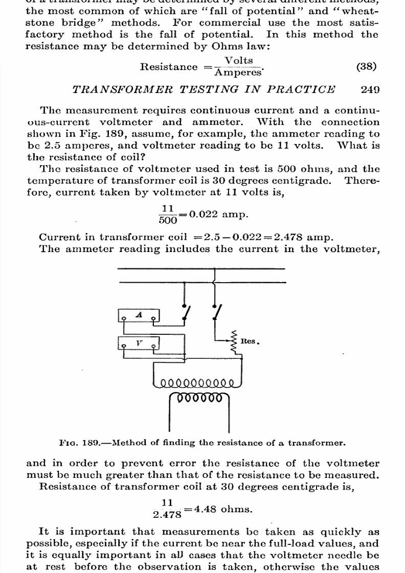
8/11/2019 Transformer Practice 1000194704
http://slidepdf.com/reader/full/transformer-practice-1000194704 261/290
TRANSFORMER
TESTING
IN
PRACTICE
249
The
measurement
requires
continuous
current
and
a
continu-us-current
voltmeter
and
ammeter.
With
the
connection
shown
in
Fig.
189,
assume,
for
example,
the
ammeter
reading
to
be
2.5
amperes,
and
voltmeter
reading
to
be
11 volts. What
is
the
resistance
of
coil?
The
resistance
of
voltmeter used
in
test
is
500
ohms,
and
the
temperature
of transformer
coil
is
30
degrees
centigrade.
There-ore,
current
taken
by
voltmeter
at
1
1
volts
is,
^
=
0.022
amp.
Current in
transformer
coil
=2.5
0.022
=
2.478
amp.
The
ammeter
reading
includes
the
current
in
the
voltmeter,
lJ I
*
Res.
nmmD
Fig.
189.
Method of
finding
the resistance
of
a
transformer.
and
in
order
to
prevent
error
the
resistance of the
voltmeter
must
be
much
greater
than that
of
the
resistance
to
be
measured.
Resistance
of transformer
coil
at
30
degrees
centigradeis,
11
2.478
=
4.48
ohms.
It
is
important
that
measurements
be
taken
as
quickly
as
possible,especially
if
the
current
be
near
the
full-load
values,
and
it is
equally
important
in
alJ
cases
that
the voltmeter
needle
be
at
rest
before the
observation
is
taken,
otherwise
the
values
obtained
will
not
be
reliable.
It
is
possible
to
have
a
current
of

8/11/2019 Transformer Practice 1000194704
http://slidepdf.com/reader/full/transformer-practice-1000194704 262/290
250
STATIONARY
TRANSFORMERS
sufficient
strength
to
heat the
coil
so
rapidly
as
to
cause
it
to
reach
a
constant
hot
resistance
before
the
measurement
is
taken.
The
resistance
of
the
transformer
coil
at
25
C,
which
is
the
temperature
coefficient
of
0.42
per
cent,
per
degree
from
and
at
0 C., is,
4.48XJ00
(0.42X5)
+100
i:-^
^^
=
4.39
ohms.
If
the
temperature
of
windings
is
different
for each
observation,
then
resistance
must
be
calculated
for
each
and the
average
taken.
If the
temperature
of
the
windings
is
the
same
for
air observa-ions,
then the
average
voltage
and
current
may
first
be deter-ined
and
the
resistance
calculated
from
the
average
values.
Copper
Loss
and
Impedance.
^When
a
transformer
is
delivering
power,
copper
loss takes
place,
varying
as
the
square
of
the
Primary
Secondary
Fig. 190.
Copper
loss
and
impedance.
current.
It
is
due
to
the
resistance
of
the
windings
and
to
the
eddy
currents
within
the
conductors themselves.
The
copper
loss
may
be
measured
at
the
same
time
as
the
impedance-drop
measurement
by
introducing
a
wattmeter
as
shown
in
Fig.
190. It
may
also
be calculated
from currents
through
conductors
and
resistance
of
conductors,
as
follows:
P
=
h^Ri
+
h^R2,
in
watts,

8/11/2019 Transformer Practice 1000194704
http://slidepdf.com/reader/full/transformer-practice-1000194704 263/290

8/11/2019 Transformer Practice 1000194704
http://slidepdf.com/reader/full/transformer-practice-1000194704 264/290
252
STATIONARY
TRANSFORMERS
sistance in
continuous-current
circuits,
hat
is
to
say,
the
ex-ression
r
^
r^
x
G.m.f.
.^^^
/
=
D
=
Current
=
~
.
(42)
R
Resistance
^ ^
for
continuous-current
circuits is
replaced
in
alternating-current
circuits
by
the
equivalent
expression,
~
\/R^+{X's^
~ ~
i
mpedance
~R-jx~Uj^^
-fhw
^^ ^
where
/
is
the
current;
E the
impressed
e.m.f.
;
Xg
the
inductive
reactance;
and
J^
the
resistance
of
the
circuit.
The
impedance
of
a
transformer
is
made
up
of
two
components
at
right
angles
to
each
other.
(Reactance
and
resistance.)
It
is
expressed
as
Z
=
\/R^+X^=
{R-jx)R
+
v'^T
Lw
(45)
Reactance
may
be
inductive,Xg,
or
condensive
Xc',
this
latter
factor
is
never
considered when
dealing
with
transformers.
X.
=
2.fL
and
X,
=^-l_
_J__
(46)
wherein
/is
the
frequency
in
cycles
per
second;
L
is
the
induct-,
ance
in
henrys;
and
C
is
the
capacity
in
farads.
The
impedance
of
a
transformer
is
measured
by
short-circuiting
one
of the
windings,
impressing
an
e.m.f.
on
the other
winding
and
taking
simultaneous measurements
of
voltage
and
current.
The
impedance
voltage
varies
very
nearly
with
the
frequency.
In
standard
transformers
the
impedance
voltage
varies
from
1
to
4
per
cent.,
depending
upon
the
size
and
design
of the
transformer.
Efficiency.
^The
efficiency
f
a
transformer is
the
ratio
of
its
net
output
to
its
input.
The
output
is
the
total
useful
power
delivered
and the
input
is
approximately
the
total
power
delivered
to
the
primary;
and
consists
of the
output
power
plus
the
iron
loss
at
the
rated
voltage
and
frequency,
plus
the
copper
loss due
to
the
load
delivered.
Example:
Find the
full-load,
and
half-load
efficiency
of
a
5-kw.,
2000
to
200-volt,
60-cycle
transformer
having
an
iron
loss
of
70
watts,
a primary
resistance
of
10.1
ohms,
a
secondary
resistance
of 0.066
ohms.
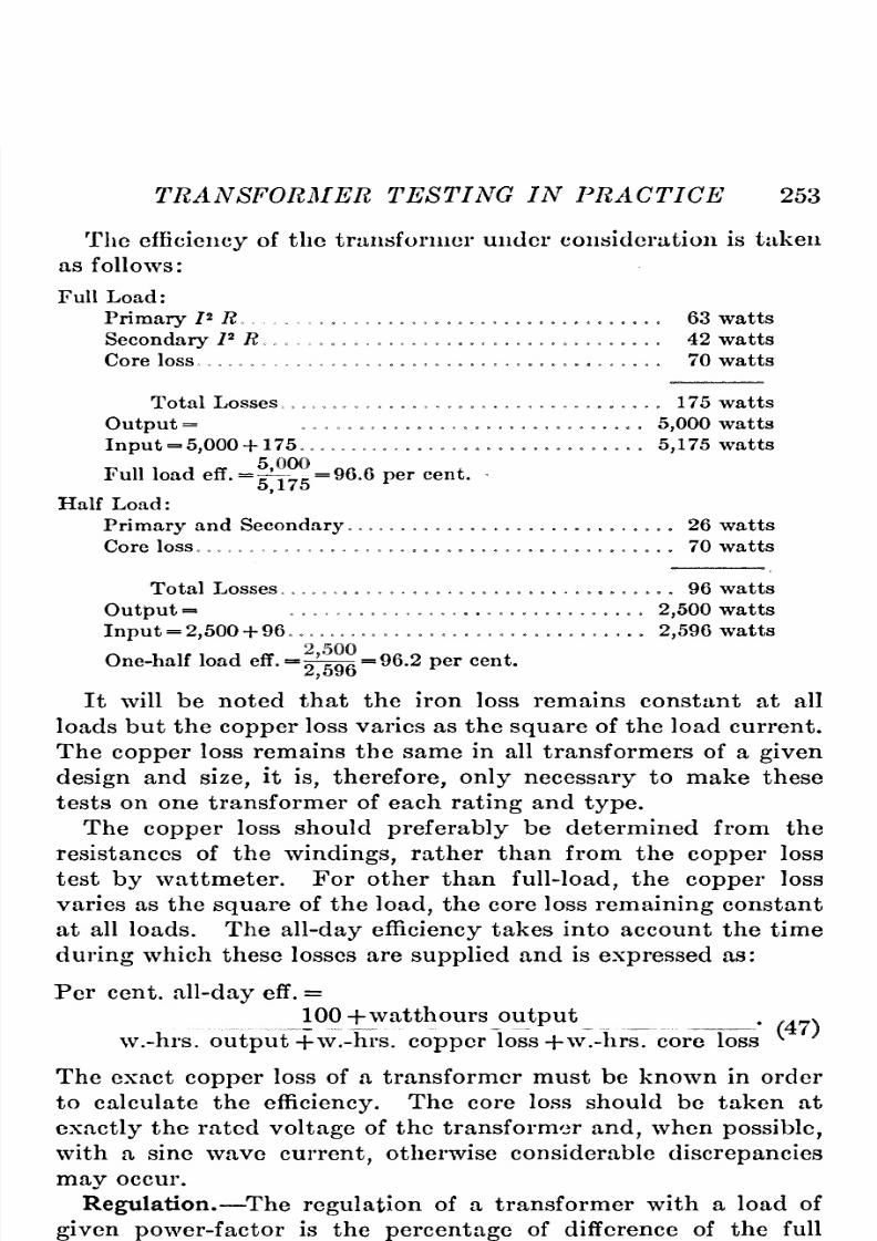
8/11/2019 Transformer Practice 1000194704
http://slidepdf.com/reader/full/transformer-practice-1000194704 265/290
TRANSFORMER
TESTING IN PRACTICE 253
The
efficiency
f
the transformer
under
consideration
is taken
as
follows:
Full
Load:
Primary
I^
R 63
watts
Secondary
PR
42
watts
Core loss
70
watts
Total Losses
175
watts
Output
=
5,000
watts
Input
=
5,000
+
175
5,175
watts
Full load
efF.
=
t^v?==96.6
per
cent.
5,175
Half
Load:
Primary
and
Secondary
26
watts
Core
loss 70
watts
Total
Losses
96 watts
Output
=
2,500
watts
Input
=
2,500
+
96
2,596
watts
One-half load eff.
=^^^-=96.2
per
cent.
It
will
be
noted
that the
iron
loss
remains
constant
at
all
loads
but the
copper
loss
varies
as
the
square
of the load
current.
The
copper
loss
remains
the
same
in
all
transformers of
a
given
design
and
size,
it
is,
therefore,only
necessary
to
make
these
tests
on one
transformer
of
each
rating
and
type.
The
copper
loss should
preferably
be
determined
from
the
resistances
of
the
windings,
rather
than
from the
copper
loss
test
by
wattmeter.
For
other than
full-load,
he
copper
loss
varies
as
the
square
of the
load,
the
core
loss
remaining
constant
at
all
loads.
The
all-day
efficiency
akes
into
account
the
time
during
which
these losses
are
supplied
and
is
expressed
as:
Per
cent,
all-day
eff.
=
100
+watthours
output
.
. v
w.-hrs.
output
+w.-hrs.
copper
loss-j-w.-hrs.
core
loss
^
The
exact
copper
loss
of
a
transformer
must
be
known
in
order
to
calculate the
efficiency.
The
core
loss should
be taken
at
exactly
the
rated
voltage
of the transformer
and,
when
possible,
with
a
sine
wave
current,
otherwise
considerable
discrepancies
may
occur.
Regulation.
^The
regulation
of
a
transformer with
a
load
of
given
power-factor
is
the
percentage
of
difference
of
the
full
load
and
no
load
secondary
voltages
with
a
constant
applied

8/11/2019 Transformer Practice 1000194704
http://slidepdf.com/reader/full/transformer-practice-1000194704 266/290
254
STATIONARY
TRANSFORMERS
primary
voltage.
It
may
be
ascertained
by
applying
full
load
to
the
transformer
and
noting
the
secondary
voltage,
then
removing
the load
and
noting
the
secondary open-circuit
voltage.
The
secondary
voltage
drop
will
be
very
much
greater
with
an
inductive
load,
such
as
induction
motors
or
arc
lamps,
than
it
will
be
with incandescent
lamps.
The
regulation
can
be
determined
by
direct
measurement
or
calculation
from the
measurements
of
resistance
and
reactance
in
the
transformer.
Since the
regulation
of
any
transformer
is
only
a
few
per
cent,
of the
impressed
voltage,
and
as errors
of
observation
are
liable
to
be
fully
1
per
cent.,
the
direct
method
of
measuring
regulation
is
not
at
all
reliable.
By connecting
the
transformer
to
a
circuit
at
the
required
voltage
and
frequency,
using
a
lamp
load
or
water
rheostat
on
the
secondary
the
regula-ion
may
be
determined.
This
method,
is,
however,
unsatis-actory,
and
much
more
reliance
can
be
placed
on
the
results
of
calculation.
Several
methods
have
been
proposed
for the
calculation
of
regulation,
ut
the
following
is
found
quite
accurate
for
inductive
and
non-inductive
loads.
For
inductive
loads:
%
regulation%X
smd+%1
R
cos
d.
(48)
=
%
E:,
sin
d+%Er cos
0.
Per
cent.
Ex
=the
per
cent,
reactance
drop.
Per
cent.
Er
=per
cent,
total
resistance
drop.
^
=
the
angle
of
lag
of
load
current
delivered.
Example.
^Find
the
regulation
of
a
transformer
which
has
a
reactance
drop
of
3.47
per
cent,
and
a
resistance
drop
of 2.0
per
cent,
when
delivering
load
to
a
circuit
having
a
power-
factor
of
87
per
cent.
The
cos
^
= 0.87 is
30
degrees.
The
sine
of
angle
30
degrees
is
0.5.
Then from
the above
formula:
Per
cent,
regulation
3.47x0.5
+
2X0.87 =
3.48.
For
non-inductive
loads:
%
Regulation
=%IR-
^^~q^^^
(49)
Per
cent.
I
R
=
per
cent,
resistance
drop.
%
X
=
'V%
impedance drop^
%
resistance
drop^=
%
react-nce
drop.
I
=
V%
exciting
current^
%
iron
loss
currents

8/11/2019 Transformer Practice 1000194704
http://slidepdf.com/reader/full/transformer-practice-1000194704 267/290
TRANSFORMER
TESTING
IN
PRACTICE
255

8/11/2019 Transformer Practice 1000194704
http://slidepdf.com/reader/full/transformer-practice-1000194704 268/290
256
STATIONARY^
TRANSFORMERS
For
non-inductive
load
O
O,
sin
O
O,
cos
0
=
1,
we
have,
therefore:
%
regulation
=%
Er
The above formula is
practically
correct
for small
values
of
angle
6,
but
the
error
becomes
greater
as
0
increases.
Another
simple
and
accurate
method
in
use
for
calculating
regulationis,
For
non-induction
loads:
TV 2
%
regulation
=7
7^20^
^^ ^
and for
inductive
loads:
%
regulation
=d
4-
2QQ
(51)
where
d
is
component
drop
in
phase
with
the
terminal
voltage
and k
is
the
component drop
in
quadrature
with
the
terminal
voltage,
IR
is
total
resistance
drop
in
per
cent,
of
rated
voltage
and IX
is
reactance
drop
in
per
cent.
Take for
example
a
7.5
kw.
60-cycle
single-phase
transformer
with
a
10
to
1
ratio,
secondary
voltage
at
full load
=
208
volts and
Sec.
resistance
=0.0635
ohms.
Primary
resistance =4.3
ohms.
Sec. 7/2
=
2.165
volts
=
0.985
%.
Primary
772
=
14.65
volts
=
0.667
%.
and
IX
=
V{%
impedance
drop)
2-
77^2=
1.8
%
For
non-inductive
load,
using
the
formula
above,
we
have
%
regulation
1.65
+^|^
1.67
%
and
For
inductive load with
a
power
factor
of,
say,
80%,
we
have
0
462
%
regulation
2.3
+
^^
= 2.33
%
where 2.3
is
taken from
formula,
and
is:
d
=
w
7X
+
772
Cos ^
=
(0.6
X
1
.8)
4-
(1
.65
X
0.8)
=
2.3
The
value
IX
(reactance
drop
in
volts)
may
also be
expressed by
the
formula
V(B.-- ^)
where
E is the rated
primary
voltage,
E^
being
the
impedance
voltage
and
is found
by
short-
circuiting
the
secondary
winding
and
measuring
the volts
necessary
to
send
rated-load
current
through
the
primary.
P
is the
impedance
watts as
measured
in the
short-circuit
teat.
8/11/2019 Transformer Practice 1000194704
http://slidepdf.com/reader/full/transformer-practice-1000194704 269/290
TRANSFORMER
TESTING
IN
PRACTICE
257
and
0.46 is from
formula,
and
is:
k =
w
IR-
IX Cos
^
=
(0.6
XI.
65)
-(1.8X0.8)
=046
where
w
is the wattless
factor of
load.
Short-circuit
Test.
For
some
time
past
it
has
been the
practice
of certain
transformer-testing
epartments
in
America
to
subject
certain
types
of
transformers
over a
given
k-v-a.
capacity
to
short-
circuit
tests
of from
5
to
25
times rated
current.
It
is
now
well
known that the
cause
of
many
burn-outs
is
due
to
the
large
amount
of
power
back
of
the transformers.
It
has also been shown that
a
certain
milling
ccurs
in
transformers,
and
after
repeated
short-circuits
the
transformer breaks
down,
its
coils
being
twisted
in
the
shell
type
and
displaced
in
the
core
type.
The
short-circuit
test
is
usually
done
at
special
times
of
the
night
so as
not
to
affect
the
voltage
regulation
of
the
system.
One
winding
of
the
transformer
is
connected
to
the
power
system
(always
many
times
the
capacity
of the
transformers)
and
the
other
winding
suddenly
short-circuited.
The
tendency
of the
coils
to
flare
out
due
to
the
excessive
magnetic
repulsion
s
the
most
importantpoint
of
the
test.
This
test
is
of
very
short
duration,
as
the
current
sometimes
reaches
as
high
a
value
as
25
to 30
times
full-load
current.
17

8/11/2019 Transformer Practice 1000194704
http://slidepdf.com/reader/full/transformer-practice-1000194704 270/290
CHAPTER
XV
TRANSFORMER
SPECIFICATIONS.
High-voltage
transformer
specifications
are
always
interesting
in
that
other
more severe
mechanical
and
electrical
stresses
have
to
be considered in their
design,
and
the
arrangement
of
coils,
their
form
and
make-up
are so
different.
Below
is
given
a
wind-ng
specification
of
a
high-voltage
transformer which
was
specially
made for
an
existing
transformer
operating
at
a
lower
voltage
(the
same
iron
being
used
over
again).
WINDING
SPECIFICATION FOR
A
WATER-COOLED
OIL-FILLED
60-CYCLE
900-KW.
22,700-39,300
TO
2200-VOLT
SINGLE-
PHASE
TRANSFORMER.
Primary Winding
Conductor
cross-section,
two
0.170
in.
X
0.080
in.
double
cotton
covered.
Weight,
750 lb. double
cotton
covered.
Inside
Section. Outside Section.
Turna
/
8
B.T.
coils
of
32
and
32
\
/
pz,
pa, pt,
p , pe, p?,
pa,
618
in.
\
2
B.T.
coils
of 27
and
26
/
\
p^,
pi,
and
pn,.
Winding
taps
made
at
end of fifth
turn
inside
end
of
outside
section
ps, p^.
Insulation
between
turns
(8300
ft.)
0.015 in.
thick
by
3/16
in.
wide, consisting
of
two
0.005
in.
hercules
parchment
and
one
0.005
in. mica.
Reinforced
Turn
Insulation
26-turn
section,
last 12
turns
(triple)
turn
insulated,
and
all
turns
0.012
\.CK
26-turn
section,
all
other
turns
(double)
turn
insulated,
and all
turns
0.012 V.C.
26-turn
section,
all
turns
(double)
turn
insulated,
and all
turns
0.012 V.C.
1
V.C.
=
varnish
cambric.
258

8/11/2019 Transformer Practice 1000194704
http://slidepdf.com/reader/full/transformer-practice-1000194704 271/290

8/11/2019 Transformer Practice 1000194704
http://slidepdf.com/reader/full/transformer-practice-1000194704 272/290
260
STATIONARY TRANSFORMERS
95
C.).
After
each
taping
the
coils
should
be
allowed
to
cool
to
at
least 100
F.
(38
C.)
before
the
next
varnishing
is
given.
The
taping
should
be
put
on
with
one-half
lap,
except
at
the
corners
of
the
coils,
here
it
should
overlap
not
more
than
one-
eighth
at
the
outside
edge.
With
single
section coils
there
should
be
added,
before
the
taping
is
put
on,
one
thickness
of
No.
2
cotton
drill,
hich is
to
be
placed
over
the
connecting
straps.
The
drill
should
extend
at
least
1
1/2
in.
each
side
of the
strap,
and
must
be
neatly
and
firmly-
tied
down
with
twine and
sewed
together
at
the outside
edge
of
the
coil,
A
tongue
of the
drill
should
extend
up
the
outside
of
the
strap
as
far
as
the
terminal,
and should
be
secured
to
the
strap
with
a
wrapping
of
cotton
tape.
Below
is
given
a
form
of
general
specification
s
presented
to
purchasers
of
transformers. The
former
is for
a
high-voltage
shell-type
transformer
and the latter
for
a
high-voltage
core-type
transformer.
GENERAL SPECIFICATIONS
FOR
A
RECTANGULAR
SHELL-TYPE
WATER-COOLED OIL-FILLED
70,000-VOLT
25-CYCLE
SINGLE-PHASE
TRANSFORMER.
General Construction.
Each transformer
to
consist
of
a
set
of
flat
primary
and
secondary
coils,
lacedvertically
nd
surrounded
by
a
built-up
steel
core,
the
coils
being
spaced
so as
to
admit
of
the free
circulation
of
oil
between
them,
which
acts
not
only
as
an
insulator
but
as a
cooling
medium
by
conveying
the heat
from
the
interior
portions
of the
transformer
to
the tank
by
natural
circulation.
The transformer
to
be
enclosed
in
a
boiler-iron
tank,
the
base
and
cover
being
of
cast iron.
The tank
to
be secured
to
the
base
with
a
joint
made
oil-tighty heavy riveting
and
caulking.
A
coil
of
pipe
for
water
circulation
to
be
placed
in
the
oil in
the
upper
part
of
the
tank
over
the
cover
and
surrounding
the ends
of the
windings,
the
combined
surface of the
coil
and
tank
being
sufficient
to
dissipate
he heat
generated
and
thus
maintain
the
oil
and
-all
parts
of
the transformer
at
a
low
temperature.
Core.
The
core
to
be
built
up
of
steel
laminations
of
high
per-eability
and
low
hysteresis
loss.
The
laminations
also
to
be
carefully
annealed and
insulated
from each other
to
reduce
eddy-current
losses.

8/11/2019 Transformer Practice 1000194704
http://slidepdf.com/reader/full/transformer-practice-1000194704 273/290
TRANSFORMER
SPECIFICATIONS 261
Windings.
The
primary
and
secondary
windings
to
be
sub-ivided
into
several
coils,
ach
built
up
of
fiat
conductors,
wound
with
one
turn
per
layer
so as
to
form
thin,
high
coils
which will
present
a
large
radiating
surface
to
the
coil.
The
conductors to
be
cemented
together
with
a
special
insulatingcompound,
after
which
an
exterior
insulating
wrapping
to
be
applied
and
separately
treated with
an
insulating
varnish,
making
a
very
durable
insulation.
A
solid
insulating
diaphragm
to
be
placed
between
adjacent
primary
and
secondary
coils,
and
to
be
rigidly
held
in
position
by
spacing
channels
covering
the
edges
of
the
coils.
The
assembled
coils,
except
at
the
ends,
to
be
completely
enclosed
by
sheets of
solid
insulation,
hich will
interpose
sub-tantial
barrier
at
all
points
between
the
winding
and
the
core.
Oil.
Each transformer
to
have
sufficient oil
completely
to
immerse
the
core,
windings,
and
cooling
coil.
In
order
to
secure
the best
insulating
qualities
nd
a
high
flashing-point,
he
oil
to
be
specially
efined and
treated
and tested for
this
use.
A
valve
for
drawing
off
the
oil
to
be
located
in
the base
of the
tank.
Water-cooling
Coil.
To consist
of
heavy
wrought-iron
lap-
welded
pipe
with
electrically
elded
joints,
nd to
stand
a
test
of
at least 1000 lb.
pressure per square
inch.
The
duty
of the
cooling
coil
is
to
absorb
that
portion
of the heat
that
cannot
be
dissipated
by
natural
radiation
from the
tank,
which will
be
made
to
fit
the transformer
closely,
and thus
minimize
the
amount
of
oil
and
floor
space.
Leads.
The
primary
and
secondary
leads
to
be
brought
out
through
the
cover,
and
to
consist
of
heavy
insulated cables
brought
through
porcelainbushings
of
ample
surface and
thick-ess.
Performance.
After
a
run
of
24
hours
at
rated
load,
frequency,
and
voltage,
the
rise
in
temperature
or
any
part
of
the
trans-ormer,
as
measured
by
thermometer,
and the
rise in
temperature
of
the
coils,
s
measured
by
the
increase in
resistance,
not to
exceed
40
C, provided
the
temperature
of the
circulating
ater
is
not
greater
than 25
C,
and that
the
supply
of
water
is
normal.
If
the
temperature
of
the
water
differs
from 25
C,
the
observed
rise in
temperature
shoul^
be
corrected
by
0.5
per
cent,
for each
degree.
The
insulation between
the
primary
coils
and
the
core,
and

8/11/2019 Transformer Practice 1000194704
http://slidepdf.com/reader/full/transformer-practice-1000194704 274/290
262 STATIONARY
TRANSFORMERS
that
between
the
primary
and
secondary
coils,
o
stand
a
test
of
140,000
volts
alternating
current
for
1
minute,
and
between
the
secondary
coils
and the
core
a
test
of double
the
normal
voltage
for the
same
length
of
time.
The
transformer
to
carry
an
overload
of
25
per
cent,
for
two
hours
without
the
temperature
rise
exceeding
55
C.
The
transformer
to
give
full
kilowatt
output
when
operating
at
90
per
cent,
power
factor without
exceeding
the
above
tem-erature
rise.
GENERAL
SPECIFICATIONS FOR
A
70,000-VOLT
25-CYCLE
CORE-TYPE
OIL-COOLED SINGLE-
PHASE
TRANSFORMER.
Core.
The
cores
to
be
built
up
with laminated iron
sheets
of
high permeability,
low
hysteretic
oss,
and
not
subject
to
ap-reciable
magnetic
deterioration.
The
sheets
to
be
carefully
annealed
and
insulated
from
each other
in
order
to
reduce
eddy-
current
losses.
Windings.
The
primary
and
secondary
windings
to
be thor-ughly
insulated
from
each other and
from
the
core
and
frame,
and
to
stand
a
potential
much
greater
than the rated
voltage
of
the
transformer.
Oil.
Each
transformer
to
have
sufficient
oil
to
cover
the
core
and
winding
when
placed
in the
tank.
The oil
to
be
specially
treated
and
refined
in
order
to
secure
good
insulating
qualities
and
a
high flashing-point.
Terminals and
Connections.
The
primary
and
secondary
leads
to
be
carefully
insulated
and taken
from
the tank
through
por-elain
bushings,
which
shall
have sufficient
surface
to
prevent
perceptible
leakage
to
the
frame
of
the
transformer.
Performance.
After
a
run
of
twenty-four
hours
at
rated
load,
voltage,
and
frequency
the
rise in
temperature
of
any
part
of
the
transformer
as
measured
by
thermometer,
and of the
coils
as
measured
by
the
increase in
resistance,
ot to
exceed
45
C,
provided
the
temperature
of
the
surrounding
air is
not
greater
than
25
C.
and the
conditions
of
ventilation
are
normal.
If
the
temperature
of the
surrounding
air differs
from
25
C.
the
observed
rise in
temperature
should
be
corrected
by
0,5
per
cent,
for
each
degree.
Insulation
between the
primary
winding
and the
core,
and
be-ween
the
primary
and
secondary
windings,
to
stand
a
test
of
140,000
volts
alternating-current
or
one
minute,
and
between

8/11/2019 Transformer Practice 1000194704
http://slidepdf.com/reader/full/transformer-practice-1000194704 275/290
TRANSFORMER SPECIFICATIONS
263
the
secondary
winding
and
the
core a
test
of
10,000
volts
alter-ating
current
for
the
same
length
of
time.
The
transformer
to
carry
an
overload of
50
per
cent,
for
two
hours
without
undue
heating
of
any
of
the
parts.
Every
manufacturer
has
his
own
particular
way
of
arranging
transformer
specifications.
One
finds
it suits
his
purpose
to
give
but
a
general
description
while
another
will
sometimes
present
useful information
and
give
a
detailed
specification
overing
the
complete
characteristics
of
the
transformer,
including
a
complete
test
record
and
general
mechanical
and electrical
description.
One
of
the best
specifications
nd
one
of
great
interest
to
all
operating
engineers
is
made
up
as
follows:
Transforyner
Detailed
Specification.'
Form
X
X
Tank
Cribs
Total
I^R
per
cent.
IR
H.T.
cable
No
long.
L.
T.
cable
No.
long.
H.T.
brushing (terminal)
No
L.T.
bush-ng
(terminal)
No
Winding
Length
Depth
.......
Width.
......
Weight
of coils
and
core
.......
Net
weight
of
oil
Weight
of tank and
cribs
Total
weight
Gallons
of
oil
Steel
curve
K. V.
A
Type
Frequency
Volts
^.T
Phase
VoltsL.T.
Amperes
Iron
Core.
Steel
End
irons
X
Iron
clusters
per
leg
Core
irons
X
Narrow
iron
clusters
per
leg
Corners
Weight
of
core
Window
.....
X
Volume
of
core
Exciting
current
Core
section
X
and
square
inches.
Length
of
mag.
path
Core
loss,
amperes
Mag.
amperes
per.
cent.
H.
T.
Winding
Amperes
Volts
Turns
Tap-
outs
No.
of
layers
Sections
per
lag
Insula-ion
coil
to
core
Insulation
between
layers
Turns
in
each
layer
per
section
Length
of
section
Space
of
ends
Space
between
sections
Insulation
exten-ion
Space
around
core
Size
of
conductor
Diam.
of
conductor Lbs.
per
M.
ft
Weight
Thickness
of
coil Mean turn
Copper
density
Resistance
(R)
Volts
per
turn
Max,
volts
per
layer
/2/2
IR
L. T.
Winding.
Volts
Amperes Taps
No.
of
layers
Insulation
between
layers
.....
Section
per

8/11/2019 Transformer Practice 1000194704
http://slidepdf.com/reader/full/transformer-practice-1000194704 276/290
264
STATIONARY
TRANSFORMERS
leg
Turns
in
each
layer
per
section
Space
between
sections
Space
at
ends
Diam.
of
conductor
Space
around
core
Length
of
sections
Weight
Insulation extension
Size
of
conductor
Lbs.
per
M.
ft
Mean
turn
Thickness
of
coil
(R)
Resist-nce
Max.
volts
per
layer
Copper
density
Volts
per
turn
IR
im
Like
all
customers'
specifications
hese
two
are
not
complete
as
they
do not
specify
the
efficiency
and
regulation
(these
two
important
factors
being
on
the
test
record
sheet
only);
the
dielectric
test
of
the
oil;
the
temperature
of the
water
necessary
to
cool
the
oil;
the
method of
supporting
the
transformer;
lifting
the
transformer,
nor
the
method
employed
in
moving
the
trans-ormer
whether
it
be
on
steel-rails,
four-wheel
truck
or
on
a
racket-frame.
The
general
characteristics
of
a
transformer
are
always
given
in
the
test
record
sheets.
A
good
example
of
such
a
sheet
is
given
below
and
is
for
a
high-voltage
ower
transformer.
TEST
RECORD
SHEET
FOR
HIGH-VOLTAGE
POWER
TRANSFORMER
(SHELL
TYPE)
1000
kw.,
25
cycle,
60,000-volt
shell-type,
single-phase
transformer
(water cooled).
H.
T.
winding
30,000
60,000 volts;
L.T.
winding
2300
volts.
H. T.
amperes
16.66;
L. T.
amperes
435.
Heat
Run.
Run
for
8
hours
at
2300
volts
L.
T.,
and
18.5
amperes
H.
T.
(a).
Run
for
2
hours
at
2300
volts
L.
T,,
and
23.2
amperes
H.
T.
(6).
Temperatures
(degrees
C.
at
end
of
run).
H. T.
by
resistance
35.0 for
(a)
and 50.0 for
(6).
L.
T.
by
resistance
37.0
for
(6)
Temperature
of oil
18.0
for
(a)
and
23.5
for
(b).
Temperature
of
water
leaving
the
transformer
10.0
for
(a)
and
(6).
Temperature
of
frame
of
transformer
12.0
for
(a)
and
16.5
for
(b).
Resistances.
H.
T.
resistance
at
25
C.
is
1796,
and
for
(b)
is
21.32
ohms.
L.
T.
resistance
at
25
C.
is
0.0223
and
for
(b)
is
0.02545
ohms.
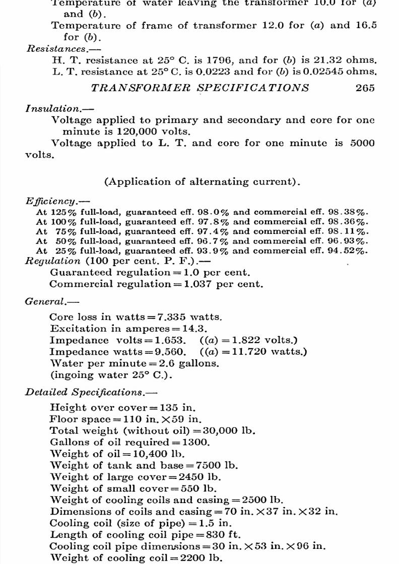
8/11/2019 Transformer Practice 1000194704
http://slidepdf.com/reader/full/transformer-practice-1000194704 277/290

8/11/2019 Transformer Practice 1000194704
http://slidepdf.com/reader/full/transformer-practice-1000194704 278/290
266
STATIONARY
TRANSFORMERS
TEST RECORD
SHEET
FOR HIGH-VOLTAGE
POV/ER
TRANSFORMERS
(CORE
TYPE)
200-kw.,
25
cycle, 57,500
volts
core
type,
water-cooled
single-phase
ransformer.
H.
T.
winding
28,750, 57,500
volts;
L. T.
winding
2300
volts.
H. T.
amperes
=
3.5;
L, T.
amperes
=
87.
Heat
Run.
Run
for
11
hours
at
2300
volts
L.
T.,
and
87
amperes
L. T.
current
(a).
Run
for
2 hours
at 2300
volts
L.
T.,
and
130.5
amperes
L. T.
current
(6).
Temperatures
(degrees
C.
at
end
of
run)
.
H.
T.
by
resistance
30.0
for
(a)
and
49.5
for
(b).
L. T.
by
resistance
38.5
for
(6).
Temperature
of
oil
21.5
for
(a)
and
28.0
for
(6).
Temperature
at
top
of frame
is
19.5
for
(a)
and
25.0
for
(6).
Temperature
at
bottom of frame
is
9.5 for
(a)
and 12.5 for
(6),
Room
temperature
for
(a)
is
18.5
and for
(b)
17.5
C.
Resistance.
H.
T.
resistance
at
25
C.
is
56.6
ohms
on
winding
connected
for
28,750
volts.
H, T.
resistance
for
(6)
is
68.1
ohms.
L.
T.
resistance
for 25
C.
is 0.1168
ohms,
and for
(b)
is
0.1307
ohms.
Insulation.
H. T.
to
L.
T.
and
core
115,000
volts
alternating
current
for
one
minute.
L.
T.
and
core
10,000
volts
alternating
current
for
one
minute.
Efficiency.-^
At
100%
load
guaranteed
eff.
96.7%
and
commercial
eff.
97.9%.
At
75%
load
guaranteed
eff.
96.2%
and
commercial eff.
97.8%.
At
50%
load
guaranteed
eff.
95.
0%
and
commercial eff.
96.8%.
At
25%
load
guaranteed
eff.
91.2%
and
commercial
eff.
94.5%.
Regulation (100
per
cent.
P.
F.
=1.6
per
cent.).
General.
Core
loss
in
watts
=2.865.
Excitation
in
amperes
=10.3.
Impedance
volts
(57,500
volt
winding)
=1.017.
Impedance
watts
=1.750.

8/11/2019 Transformer Practice 1000194704
http://slidepdf.com/reader/full/transformer-practice-1000194704 279/290

8/11/2019 Transformer Practice 1000194704
http://slidepdf.com/reader/full/transformer-practice-1000194704 280/290
268
STATIONARY TRANSFORMERS
Also,
comparing
the
largest
water-cooled
oil-insulated
trans-ormer
made
in
Europe
with
an
ordinary
4000
kw.
standard
American
design
of the
same
type,
we
have:
4000-KW., 33,000-VOLT,
OIL-INSULATED WATER-COOLED
SINGLE-PHASE TRANSFORMER
(American manufacture)
Dimensions,
107
in.
X63
in.
X150
in.
high)
Kilowatts
per
square
foot
86
Kilowatts
per
cubic
foot
6
.
85
Gallons of
oil
1950
Gallons
per
kilowatt
0.49
Full-load
efficiency
98.9
per
cent.
Half -load
efficiency
98
.
5
per
cent.
Gallons
of
water
per
minute
19
.
5
Frequency
25
5250-KV-A.,
45,000-
VOLTS
OIL-INSULATED,
WATER-COOLED,
THREE-PHASE
TRANSFORMER
(European
manufacture)
(Dimensions,
82
in.
X59
in.
X136
in.
high)
Kilowatts
per square
foot
162
Kilowatts
per
cubic
foot
14.2
Gallons of oil
1130
Gallons
per
kilowatt
0.
215
Efficiency
at
full-load
98
.
95
per
cent.
Efficiency
at
50
per
cent, load
98.85
per
cent.
Regulation
(P.
F.
=
1.0)
0. 62
per
cent.
Regulation
(P.
F.
=0.8)
3
.
0
per
cent.
Frequency
50
Transformers
of
a
much
greater
size
than
5,000
kv-a
at
45,000
volts have
not
yet
been
built in
Europe.
In American
single-
phase
units
of 7500
kw.,
and
three-phase
units
of
14,000
kw,
are
in
operation
at
voltages
above
100,000
volts.
The three
following high-voltage
power
transformers will
serve
to
show what
is
being
done
in this
direction:
7500-KW.,
60,000-VOLT,
OIL-INSULATED,
FORCED
OIL-COOLED,
SHELL-TYPE
THREE-PHASE TRANSFORMER
Kilowatts
per
square
foot
80
Kilowatts
per
cubic
foot
5.65
Gallons
of
oil
4000
Gallons of oil
per
kilowatt.
0.53
Efficiency
at
full-load
98
.
95
per
cent.
Weight
without oil
42
.
5
tons.
Frequency
25

8/11/2019 Transformer Practice 1000194704
http://slidepdf.com/reader/full/transformer-practice-1000194704 281/290
TRANSFORMER SPECIFICATIONS
269
5750-KW.,
138,500-VOLT,
OIL-INSULATED,
WATER-COOLED,
SHELL-TYPE SINGLE-PHASE TRANSFORMER
Kilowatts
per
square
foot 71
Kilowatts
per
cubic foot
5.3
Gallons
of
oil
2500
Gallons
of
oil
per
kilowatt
0.7
Efficiency
at
full-load
98
.
8
per
cent.
Efficiency
at
75
per
cent,
load 98.7
per
cent.
Efficiency
at
50
per
cent,
load
98.3
per
cent.
Efficiency
at
25
per
cent,
load
96.9
per
cent.
Total
weight
in
tons
28
Frequency
60
Test
voltage 280,000
volts.
(Length
of
high-voltage
winding
is
4
miles)
10,000-KW.,
100,000-VOLT,
OIL-INSULATED,
FORCED
OIL-COOLED,
SHELL-TYPE
THREE-PHASE TRANSFORMER
Kilowatts
per square
foot
58
.
7
Kilowatts
per
cubic
foot 3
.
25
Gallons of
oil
1500
Gallons
of
oil
per
kilowatt
0.75
Efficiency
at
full-load
99
per
cent.
Weight
without
oil
60
tons.
Frequency
60
(The
primary
winding
(high-voltage
winding)
consists of
10
miles of
copper
conductor)
Practically
every
high-voltage alternating-current
three-phase
system
operating
at
55,000
volts and above
are
given
in
the
table Modern
High-voltage
Power
Transformers
operating
at
the Present
Time.
The
transformer
connections
are
as
38
for
star
against
21
for
delta
(the
star
connections
being
in
some
cases
solid
grounded
and
in others
grounded through
a
high
resistance
while
the delta connections
are
all
insulated).
In
Chapter
IV
several
important
advantages
and
disadvantages are
given
for
delta and
star
connections,
in
looking
through
the
list
of
the
highest
voltage
transformer
installations
practice
appears
to
point
toward
the
star
connection.
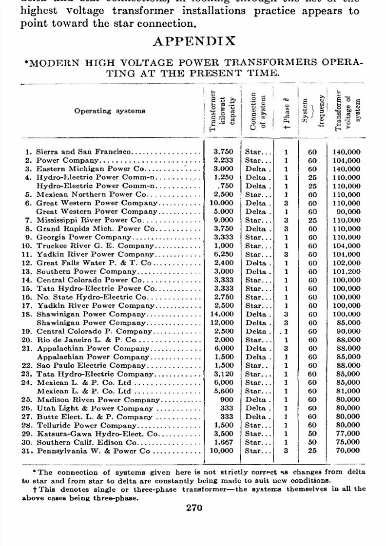
8/11/2019 Transformer Practice 1000194704
http://slidepdf.com/reader/full/transformer-practice-1000194704 282/290
APPENDIX
MODERN
HIGH
VOLTAGE
POWER
TRANSFORMERS
OPERA-ING
AT
THE
PRESENT
TIME.
Operating
systems
I
S
i
as
X
I
C8
P
1.
Sierra
and
San
Francisco
2.
Power
Company
3.
Eastern
Michigan
Power
Co.
.
. .
4.
Hydro-pjlectric
Power Comm-n.
Hydro-Electric
Power
Comm-n.
5.
Mexican
Northern
Power
Co.
.
.
6.
Great
Western
Power
Company.
Great
Western
Power
Company.
7.
Mississippi
River
Power
Co.
. .
.
8.
Grand
Rapids
Mich.
Power
Co.
9.
Georgia
Power
Company
10.
Truckee
River
G.
E.
Company.
.
11.
Yadkin
River
Power
Company.
.
12. Great Falls Water P. T. Co..
13.
Southern
Power
Company
14.
Central
Colorado
Power
Co.
.
. .
15.
Tata
Hydro-Electric
Power
Co.
.
16.
No.
State
Hydro-Electric
Co.
. .
17.
Yadkin
River
Power
Company.
.
18.
Shawinigan
Power
Company.
.
. .
Shawinigan
Power
Company.
. .
.
19.
Central
Colorado P.
Company..
20.
Rio
de
Janeiro
L.
P.
Co
21.
Appalachian
Power
Company.
.
.
Appalachian
Power
Company.
. .
22. Sao
Paulo
Electric
Company.
.
.
23.
Tata
Hydro-Electric
Company..
24.
Mexican
L.
P.
Co. Ltd
Mexican
L.
P.
Co.
Ltd
25.
Madison
Riven
Power
Company
26.
Utah
Light
Power
Company
.
27.
Butte
Elect.
L.
P.
Company
. ,
28.
Telluride
Power
Company
29.
Katsura-Gawa
Hydro-Elect.
Co.
30.
Southern
Calif.
Edison Co
31.
Pennsylvania
W.
Power
Co
. .
140,000
104.000
140.000
110,000
110,000
110.000
110.000
90.000
110.000
1
10,000
110,000
104,000
104,000
102,000
101.200
100,000
100,000
100,000
100,000
100.000
85,000
90,000
88.000
88.000
85.000
88,000
85,000
85,000
81,000
80.000
80.000
80.000
80.000
77.000
75.000
70.000
The
connection of
systems
given
here
is
not
strictly
correct
is
changes
from
delta
to
star
and
from
star
to
delta
are
constantly
being
made
to
suit
new
conditions.
t
This
denotes
single
or
three-phase
transformer
the
systems
themselves
in
all
the
above
cases
being
three-phase.
270

8/11/2019 Transformer Practice 1000194704
http://slidepdf.com/reader/full/transformer-practice-1000194704 283/290
APPENDIX
271
MODERN
HIGH
VOLTAGE
POWER
TRANSFORMERS OPERA-ING
AT
THE
PRESENT
TIME.
(Continued.)
Operating
systems
32. Missouri River Power
Co
33. Southern
Wisconsin Power Co.
.
34.
Kern
River
Power
Company.
.
. .
35.
Northern
Calif.
Power
Co
36.
Yakima
Valley
Power
Company
37.
Central
Georgia
Power Co
38.
Northern
Hydro-Electric
Co
39.
Eastern
Tennessee Power
Co.
.
.
40.
Idaho-Oregon
L.
P.
Company
41.
Spokane
Inland E. R. Co
. . .
42.
Nagoya
Electric Power
Co
43.
Toronto
Power
Company
,
44.
Washington
Water
Power
Co.
. .
45.
Mexican
L.
P.
Co.
Ltd
46.
East-Creek
L.
P.
Company.
. .
47.
Great
Northern Power
Co
48.
Niagara-Falls
Power
Company.
49.
Pacific Coast
Electric Co
50.
Guanajuato
Power
E.
Co.
. .
.
51.
Jhelum River
Electric
Co
52.
Michiacan Power
Company.
.
.
.
53.
Elect.
Development
Company.
.
61.
Puget^Sound
Power
Company.
.
55.
Canadian-Niagara
Power
Co
50.
Portland L. P.
Company
57.
Calif. Gas
Electric Co
58. Pacific
Coast
Power
Company
.
.
69.
Winnipeg
L. P.
Company.
. . .
60.
a
.
a
60
60
50
60
60
60
25
60
60
25 60
GO
25
60
60
25
25
60
60
60
25
60
25
60
26
60
60
60
60
u
^
O
O M V
S
*
to
O
o
70,000
70,000
67,500
66,000
66,000
66,000
66,000
66.000
66,000
66,000
50,000
60,000
60,000
60,000
60,000
60,000
60.000
60,000
60,000
60,000
60,000
60,000
60,000
67,000
57,000
55,000
55,000
65,000
The
subject
of transformers
cannot
very
well be
concluded
without
a
reference
to
the
effects
of
altitude
on
their
operation.
It is
deemed
safe
to
say
that
not
one
of
the above
mentioned
systems
took
this effect
of
altitude into consideration
when
specifying
their
system
requirements,
yet
each and all
were
careful
to note
that the
common
every
day
specifications
nd
tests
were
complied
with.
With
the
exception
of water-cooled oil
transformers,
manu-acturers
should
specify
the
temperature
rise
and
efficiency
f
transformers
at
service-altitudes. This
is
very
important
for
the
reason
that
insulation,
temperature
and
efficiency
values
are
quite
different
at
high
altitudes
to
those
at
sea
level. For
example,
at
an
altitude
of
3,500
ft.
above
sea
level
a
higher
kv-a
rating
should be allowed
a
given
unit
and,
when
a
trans-
8/11/2019 Transformer Practice 1000194704
http://slidepdf.com/reader/full/transformer-practice-1000194704 284/290
272
APPENDIX
former is
rated
for
operation
at
this
altitude,
the
normal
per-issible
temperature
rise should be
reduced
by
approximately
1
per
cent,
for
every
additional
350-ft. rise
at
which
it is
put
into
service,
that
is
to
say:
at
an
altitude
of
10,500
ft.
the
per-
permissible
temperature
rise would be
approximately
10,500
V-
350 =30
per
cent.
LESS,
thus
we see
that
for
higher
altitudes
a
given
transformer
will
have
a
different
rating
for
a
given
service.

8/11/2019 Transformer Practice 1000194704
http://slidepdf.com/reader/full/transformer-practice-1000194704 285/290
INDEX
Ability
of
a
transformer
to
deliver
Centralized
system
over
200,000
kw.,
current
at
a
constant
volt-
3
age,
16
Admittance,
31,
32
Advantage
of the
delta-delta
to
delta-delta, 74,
75
delta-star
to
star-delta
system,
74,
75
Advantages
of
iron
and air
reactance
coils,
159
Aging
of the
iron,
11,
15
Air and iron
reactance
coils,
159
Air-blast
transformers,
7,
120,
144
Air-chambers
for
transformers,
144
Air-cooling
of
transformers,
120-122
All-day
efficiency,
14,
15
Alloy
steel
in
transformers, 11,
246
Alternating
currents
dangerous
and
impracticable,
3
fought
in the
Law
Courts,
3
American and
European
engineers,
79
American
I.
E.
E.,
239
Amount
of heat
developed
in
a
transformer,
6
hysteresis
in
a
given
steel,
8
Anhydrous
copper
sulphate,
132
Arc-series
lighting,
178-185
Assembly
of
large
power
transform-rs,
136-148
Auto-transformers
and transforma-ion,
33,
170-177
Automatic
regulators,
224-226
Balancing
transformer,
26,
27
Best
shape
of transformer
core,
11
Best
operated
system,
74
Blotting
paper,
133
Breathing
action,
125
Building
of
fire-proof
construction,
8
Capacity
in
kw.,
3,
52
Causes
of transformer
failure,
145,
154
Central
station
engineers
and
man-gers,
153
Cheap
copper
space
and
alloyed
iron,
153
Cheapest
cost
of
system,
74
Changing
of
frequency
(using
trans-ormers),
83
Change
any
polyphase
system
into
any
other
system,
35
Chief
danger
of
fire,
8
Choice
of transformer
system
con-ections,
70,
74
Cleaning
of transformer
cooling-
coils,
125
Close
regulation,
156
Coefficients
of
resistivity
in
copper
Table,
240
Comparison
of shell and
ore
type
transformers,
150-153
Comparison
of
single-phase
and
polyphase transformers,
43
Comparative
weights
of transform-rs,
42
Commercial
manufacture
of
175,000
volt
power
transformers,
3
Common
return
wire,
32,
39,
49
Combination method of
cooling
transformers,
122
Compensators,
218-220
Connections
for
grounding
three-
phase
transformers,
81
Connections
for
grounding
two-
phase
transformers,
39
Consolidation and concentration of
systems,
158
Constant
current
transformers,
14,
178,
185
potential
transformers,
4,
etc.
Construction
of
large
power
trans-ormers,
136 144
of
constant
current
transform-rs,
182-184
18
273
8/11/2019 Transformer Practice 1000194704
http://slidepdf.com/reader/full/transformer-practice-1000194704 286/290
274
INDEX
Contact-making
voltmeter,
224-226
Control
of
the
designer,
9
Conversion
of
one
polyphase
system
into
another,
20
Conventional
connections for
trans-ormers,
56
Cooling
of
transformers,6,
117-130
Cooling-coil
cleansing,
125
Cooling
medium,
153
Copper
or
I^ R loss in
transformers,
9,
16,
250-252
Cost
of
a
given
volume and
area,
9,11
Core
of the
transformer for
a
given
service,
5, 75,
153
loss
or
iron
loss,
8, 11,
14,
245-
248
type
transformers,
10,
24,
125,
136,
137-139,
150-153,
158,
262
Cost of
total
losses,
6
Current,
short-circuit,
54, 156,
257
transformers,
186-208
Dangerous
and
impracticable
cur-ent,
3
'Dead,
short-circuit,
54
Dear
copper
space
and
ordinary
iron,
153
Delta-connected
systems,
42,
53
-star
systems,
47,
53,
73
-star
merits,
53,
73
-delta
systems, 47, 54,
73
-delta
merits,
48,
53,
73
Demerits
of the delta-delta
system,
74-75
-Design
of oil-insulated
transformers,
118
Determination of
temperature
rise,
Development
of
transformers,
2
of the
art
of
transformer
con-truction,
1
Diametrical
system,
116
Difference
of
potential,
34
of
opinion as
regards
grounding,
28
Difficulties of
three-phase
operation,
84-96
Different
ways
of
applying
trans-ormers,
22
Disadvantage
of
the
delta-delta
system, 74,
75
of
the
T
(two
transformer)
system,
80
Disc-shape coils,
129
Distribution
transformers,
28
Disturbed
system
due
to
incoming
surges,
75
Dividing
each
secondary
coil of
transformers,
24
Double-delta
system,
109, 113,
116
-star
system,
109, 114,
116
-tee,
system,
114,
116
Drop
due
to
load,
31,
32
Drying
of
insulation,
145
out
of
power
transformers,
146-
148
Duration
of
tests,
13
Early
development
of
transformers,
1
Earth
connections,
163
Earthing
of the neutral
of
trans-ormers,
161
Economy
of
copper,
30
Eddy-current
loss,
8,
245-247
Edison,
Thos.
A.,
three-wire
system,
51
Effect of various iron
substances,
1
1
Efficiency
of
transformers,
14, 16,
153, 252,
253
Electrical characteristics of
a
trans-ormer,
5
Electro-magnetic
properties
of
alloy-
steel,
11
Electro-static
capacity
of
parts
too
high,
95
Equal
output
and
change
in
copper
loss,
9
Engines,
3
Exciting
current,
9,
10
External
and internal
choke-coils,
59
Factory,
transformers
from
the,
26
Faraday's
historic
experiments,
1
Favor of the
shell-typetransformer,
152
of the
core-type
transformer,
152

8/11/2019 Transformer Practice 1000194704
http://slidepdf.com/reader/full/transformer-practice-1000194704 287/290

8/11/2019 Transformer Practice 1000194704
http://slidepdf.com/reader/full/transformer-practice-1000194704 288/290
276
INDEX
Lamps,
arc
and
incandescent,
178-
185
Large
commercial
power
trans-ormers,
generators,
etc.,
3
Law
courts
and
alternating
currents,
3
Leakage
reactance
of the
trans-ormer,
154
Least
potential
strain
on
system,
74
Liberal oil ducts between the
vari-us
parts,
6
Lighting
transformers,
31
Limiting
feature of
transmission,
resistance,
163
Limit
of
temperature
rise
in
trans-ormers,
6
Line-drop
compensator,
221-225
Long-distance
transmission
lines,
151
Losses,
8,
79
Loss due
to
magnetic
leakage,
10
to
magnetizing
current,
10
in
revenue
due to
transformer
failure,
6
Low
average
operating
temperature,
6
Lowering
the
frequency
of
supply,
9,
83
Lowest
price
for
transformers,
74
Magnetic
densities of
transformers,
14
leakage,
16
Magnetizing
currents
in
transform-rs,
11
Mechanical failure
of
transformers,
76,
152, 153,
155,
160
Mercury
thermometers
for
tem-erature
readings,
147
Merits
of the delta-star
to
star-delta
system,
74,
75
of
three-phase units,
43
Method of
connecting
three-phase
systems,
42
two-phase
systems,
30,
33
of
insulating
transformers,
11
Methods of
cooling
transformers,
117-130
Meyer
and
Steinmetz
systems
the
same
thing,
106
(Fig.
101
A)
Modern
high
voltage
power
trans-ormers,
270,
271
Moving
of
coils and
core,
94, 154,
160
Motor
auto-starters,
219,
220
National
Board
of Fire Under-riters,
227
National
Electrical
Code,
28
Negative
direction,40,
56,
244,
245
Neutral
point,
39,
49, 76,
81, 86,
161
Ohm's
Law,
248,
252
Ohmic
drop,
16,
42
Oil
for
transformers,
127,
130-135
-filled
self-cooled
transformers,
7
transformers in
separate
com-artments,
8,
144
Open-delta
V
system,
51, 52, 53,
72
Operation
of
transformers,
153-169,
178-184
Operating
at
the end of
long
lines,
1
engineer'sdifficulties,
4
Operation
of
constant current trans-ormers,
178-185
Opposition-test,
36
Over-potential
test,
229
Parallel
operation,
22, 38, 56, 64,
66,
78,
91,
239
Phase
relations,22, 59,
68,
74,
87
Phase-splitting
methods,
21
Points
in
the
selection
of
trans-ormers,
5
Polarity
of
transformers,
55,
58,
59-
64,
243-245
Polyphase
regulators,
220-226
Positive
direction,
40, 56,
244-245
Power
(P)
or
electrical
energy,
31
factor,
10, 16, 19, 22,
203-204
limiting
capabilities
of react-nce,
158
transformers, 43,
56,
66,
123,
145, 153,
267-271
Practicable
50,000
and
60,000
volt
systems,
3
Primary windings
of
transformers,
with
R and
X.,
5

8/11/2019 Transformer Practice 1000194704
http://slidepdf.com/reader/full/transformer-practice-1000194704 289/290
INDEX 277
Principal
argument
for
grounding
transformers,
28
Puncturing
of the
insulation
between
turns,
94,
117
Raising
current,
205
Ratio of
high voltage
to
low
voltage
turns, 65,
67
of iron
and
copper
loss,
5
of
transformation,
65,
67,
239-
241
Reactance,
internal and
external,
154,
160
Recognized
commercial
operation
of
60,000
volts,
3
Receiving
station
transformers,
74
Record
sheet of
tests,
264-269
Regulation,
10, 16, 22, 155,
223,
253-
256
Regulators
and
compensators,
209,
226
Relays
for
protection
of
trans-ormers,
165-167
Reliability
f
transformers
in
service,
80,
151,
154
Resistance
(R),
18, 41,
248-250
per
phase,
31
of
wiring,
31
Revenue
effected
imperfect
iron
of
a
low
grade,
1 1
loss
due
to transformer
failure,
Roasting
of oils
due
to
over-load,
154
Safety
to
life
and
property,
5,
154
Salt
for the earth
connections,
165
Scott,
Chas.
F.,
system,
53,
80,
98,
106
Secure the desired
copper
loss,
9
Self-cooling
transformers,
117-120,
144
induction,
18
Short-circuits,
8
-circuit
stresses,
154,
156,
257
Shell
type transformer,
2,
10, 73, 79,
128,
139-144,
260
Series
enclosed
arc
lighting,
78-180
lighting
from
constant
current
transformers,
205
Series-pai'allel
peration,
152
step-up
transformer,
205
transformers,
186-208
Simple
transformer
manipulations,22
Single-phase
systems, 22, 42,
83
from
three-phase,
82,
83
Six-phase
transformation
and
opera-ion,
109-116
Solid
compounds
for
impregnation
of
windings,
11
insulation,
1
Spark-gap
Table,
228
Specifications
of
transformers,
258-
270
Star
or
Y
system,
41-53
-delta
system,
47,
53,
73,
74
merits,
47,
73,
74
-star
system,
47,
53,
55
versus
delta,
71, 73,
74
Station
equipment
and
transmission
lines
greater,
10
Standard
rules of the
A.
I. E.
E.,
239
voltage
test,
231
Steam turbines
of
40,000
h.p.
ca-acity,
3
Steinmetz,
Chas.
P.,
system,
100,
106
Step-up
current
transformers,
205
-down
transformers,
4
-up
transformers,
4,
23
Strain
between
high
and low
voltage
windings,
27
Stillwell,
ewis
B.,
regulator,
210
Surges,
75,
159,
163
System
giving
cheapest
cost,
74
Switches,
76,
165
Switching
and its
advantages, 76,
165,
109-116
Taylor,
William
T.,
system,
37,
71,
80,
106,
255
T two-transformer
system, 37,
53,
71,
80,
98
three-transformer
system, 37,
71,
80
Telephone
transformers,
206
Temperature
rise
of
the
oil,
128
of electrical
apparatus,
7,
147

8/11/2019 Transformer Practice 1000194704
http://slidepdf.com/reader/full/transformer-practice-1000194704 290/290
278
INDEX
Temperatures,
123,
125,
128, 152,
232-239
Two-phase,
to
single-phase,
5,
36
multi-wire
distribution,
36