transformer life management (tlm) bulletin
TRANSCRIPT

TRANSFORMER LIFE MANAGEMENT (TLM) BULLETIN:
Excitation current
1Excitation current www.megger.com/tlm
Introduction:
Transformers are important nodes in a power circuit – transforming voltage up and down depending on the circumstances (e.g., higher for more
efficient transport of power over long distances and ultimately lower to a required consumable level). Remarkably, a transformer is a true physical
break in a power circuit, as accurately depicted by its symbol used in one-line diagrams (Figure 1). Nevertheless, a transformer is a nearly seamless
node; in other words, practically all of the power that comes in, goes “through” and out of the transformer with relatively little loss.
FIGURE 1: Transformer symbol used in one-line diagrams
“Transformer action”, which can be summarized as ‘the use of a magnetic field established by the current flow through one winding to induce
voltage in another winding’, is the phenomenon that allows for continuous power transfer across these physical breaks (a.k.a., the transformers) in an
electrical power circuit. The difference in the relative number of turns between each of a transformer’s windings is what facilitates the corresponding
transformation in output voltage as compared to input voltage.
Excitation current is a representation of the energy required to create and sustain transformer action. This includes energy that is consumed by losses
as well as recoverable energy (i.e., electrical and magnetic). Accordingly1 , transformer action is an on-going process and not a “pay the meter once”
sort of proposition. A specific, formal definition of excitation current is the rms current2 supplied to a transformer by a power source at a specified
frequency that is necessary to develop a specified voltage across specified terminals of the transformer while no load current is flowing into any
winding of the transformer [1].
In an ideal transformer, there would be no current flow in its energized primary circuit if the transformer is not serving a load, or in other words, when
there is no current flow in the transformer’s secondary circuit(s), because primary current emulates secondary current. However, in a real transformer,
even with no connections to the transformer’s secondary terminals (e.g., open circuited secondary windings and hence no secondary current), current
will be drawn through the primary windings when the transformer is energized – this is the excitation current.
These three, foregoing components are all included in an excitation current measurement, Iex (Figure 2). More
specifically, the first component of an exciting current measurement is the magnetizing current, represented by
IL, which is required to build a magnetic field in the transformer core. Typically, this constitutes the predominant
part of an exciting current measurement.
The second is a resistive current, or IR, which is a measure of losses – the amount of energy consumed in the
process of establishing transformer action and lost as heat. This includes core losses, such as hysteresis and eddy
losses, and, to a relatively much smaller degree, losses of the turn-to-turn insulation.
Finally, the third component is capacitive current, or IC, required to build the electrical field in the insulation. This
capacitive component is negligible in many cases3.
1 Energy = Power x Time
2 Excitation current is not sinusoidal and contains odd harmonics, predominantly third harmonic current. Excitation current is recorded by an RMS meter that reads the square roo
of the sum of the squares of the harmonic currents
3 In extra high voltage transformers, the capacitive current may be of the same order of magnitude as the magnetizing current as the quality of core steel is notably good, thereby
lowering magnetizing current (IL) requirements. In fact, combined with higher turn-to-turn capacitance as a means to control impulse voltage distribution, it is no longer unusual to
encounter specimens where the capacitive current contribution exceeds the inductive.
1
TRANSFORMER LIFE MANAGEMENT (TLM) BULLETIN:
FIGURE 2: Excitation
current components
Every transformer has a unique excitation current because:
1. the energy required to create and sustain transformer action is different for each transformer,
2. the amount of losses that occur during the process of establishing and maintaining transformer
action is different,
3. and the amount of energy required to electrically charge insulation between parts involved in
the process (e.g., winding turn-to-turn insulation) is different for each transformer.

Excitation current
2Excitation current www.megger.com/tlm
Factory test:
Excitation current is measured in the factory together with the no-load losses of the transformer. This 2 in 1 test is aptly called the “No-load loss and
excitation current test” and is a test used to prove manufacturer performance guarantees4. If no-load losses exceed guaranteed values, reasons may
include manufacturing mistakes or problems, so this factory test at once provides concurrent diagnostic assessment.
The transformer is excited with three-phase rated voltage at rated frequency for the test. The test instruments are typically placed on the low side
winding of the transformer with the other windings open circuited. The measured excitation current is expressed as a percent of the winding’s rated
current.
Field test:
In the 1960’s, the idea emerged to perform excitation measurements in the field using a traditional power factor test instrument. Power factor
instruments supply AC voltage and measure current so met a fundamental requirement to perform this test. This subsequently developed into a
routine field test that has provided significant diagnostic value ever since.
The exciting current field measurement, as it is called, is typically made on the highest voltage winding of a transformer because of limited output
capabilities of traditional portable field test instruments 5, which typically fall below that which is required to successfully excite a meaningful number
of transformers/voltage regulators from their respective low voltage windings (at a desired high test voltage6) . Simply put, a transformer’s HV winding
has a higher open-circuit impedance, Zm, than its LV winding so a test instrument is burdened less when trying to excite the transformer from the HV
winding. Two test parameters, AC current and loss (reported in Watts), are measured during the test. Also, an indication of whether the capacitive or
inductive component dominates the exciting current test result is provided, which is important to know for analysis.
The open-circuit or magnetizing impedance, Zm, of a transformer, comprised of resistance (related to the losses measured in the test) and reactance
(including a non-linear inductance and a capacitance component), represents the total opposition to the flow of excitation current (Figure 3). Since
the magnetizing impedance of a transformer is non-linear7 , a comparison cannot be made between measurements made at different voltages. This
means that ‘exciting current and loss’ measurements made in the field at 10 kV (and with single-phase excitation) cannot be compared to the factory
excitation measurement made at rated voltage (and with 3 phase excitation). For this reason, some customers specify the inclusion of 10 kV, single-
phase exciting current tests at the factory8.
4 No-load losses are also used as a test parameter for temperature rise tests.
5 Most instruments provide up to 300 mA – 500 mA output current at 10 – 12 kV.
6 This is true when attempting to excite the LV winding using a 10 – 12 kV test voltage. Depending on the transformer/voltage regulator, a 300 mA exciting current may easily be
exceeded at this voltage. Lowering the test voltage lowers the excitation current of the transformer/voltage regulator that must be measured..
7 Its characteristics change with applied voltage
8 So that there is something with which to compare first exciting current measurements made in the field.
FIGURE 3: Open-circuit or Magnetizing Impedance, Zm

Excitation current
3Excitation current www.megger.com/tlm
Diagnostic capabilities of an exciting current field test:
An exciting current test has many diagnostic capabilities, which collectively provide information regarding a transformer’s dielectric, magnetic/thermal,
and mechanical health.
Not only was its start as a field measurement facilitated through the use of a power factor test instrument, it turns out that an exciting current test’s
use as a dielectric assessment tool fills a notable lapse of the power factor/dissipation factor (PF/DF) and capacitance test. During a PF/DF test on a
transformer, the windings are short-circuited to create equipotential test electrodes. While this enables testing of insulation between test electrodes,
with the windings short-circuited, there is no field imposed on the insulation between the turns of the windings so the turn-to-turn insulation is
not tested. However, this is not the case with the exciting current test, which, as an open-circuit test, provides this assessment of the turn-to-turn
insulation.
Dielectric faults that may be revealed by an exciting current measurement include:
n Winding turn-to-turn short-circuited conditions,
n Partial turn-to-turn short-circuited conditions,
n Winding to ground short-circuited conditions,
n Tracking problems in the insulation (e.g., Tracking that may develop somewhere
along a winding to ground or phase winding-to-adjacent phase winding electrical tracking)
It is noted that a principal strength of the exciting current test as compared to other diagnostic tests that are similarly known for their abilities to detect
short-circuited conditions (i.e., turns ratio, winding resistance, and sweep frequency response analysis) is an exciting current test’s unique ability to
detect partial turn-to-turn short-circuited conditions; something that these other methods cannot ‘see’. This is a condition whereby one (or few) of
several strands that comprise the winding conductor of a turn short-circuit to one (or few) of several strands that comprise the winding conductor of
an adjacent turn. In other words, this is a developing but not full blown short-circuited turn-to-turn fault.
Exciting current testing is one of few electrical diagnostic tests that provide information about a transformer’s magnetic circuit integrity9 . It is able to
detect many core issues such as:
n Core lamination insulation damage,
n Core joint dislocations,
n Changes in a transformer core’s characteristics,
n Abnormal circulating currents in the core (which may be caused by an unintentional core ground(s) 10)
n And core construction problems (e.g., manufacturing defects and poor workmanship) of newly manufactured
transformers.
It is noted that some of these foregoing problems may also be accompanied by an over-heating condition of the transformer.
From a mechanical health perspective, the diagnostic reach of an exciting current test with regard to tap changers, both de-energized (DETC) and
on-load (OLTC), is impressive. Particularly for reactive style on-load tap changers (OLTC), measuring the exciting current and loss is a very powerful
diagnostic test. Examples of tap changer problems that may be detected and in many cases, identified, by this test include:
n Coking and excessive wear of contacts
n Loose moveable contacts
n Misalignment
n Improper wiring between the tap winding and the OLTC
n Reversed connections to the preventive autotransformer (PA) in an OLTC
n Sheared pin/ sheared mounting bolt on the linkage that operates the reversing switch [2]
9 Others include the magnetic balance test and sweep frequency response analysis (SFRA)
10 But generally, exciting current tests are not a consistently effective method with which to confirm the existence of unintentional grounds. Unintentional core grounds may go
completely unseen by an exciting current measurement. It is much better to turn to a DC insulation resistance test on the core for this purpose.
Excitation current
4Excitation current www.megger.com/tlm
n Problems in an OLTC’s preventive autotransformer (PA), series autotransformer or series transformer such as open-
circuited turns, short-circuited turns or high resistance connections
Furthermore, with regard to general winding problems, in addition to turn-to-turn winding short-circuits (mentioned earlier), the exciting current test
is able to detect some open-circuited conditions, largely dependent on the winding or location of the open-circuit. However, open-circuit conditions
are generally much more reliably diagnosed through the use of a DC winding resistance test. For example, an open-circuit in the secondary winding
or tap windings will usually not be visible in an exciting current measurement.
How does it work?
When excitation current is drawn by a transformer from a power source, flux builds in the transformer core and will induce a voltage in each turn
of every winding it intersects, including that of the energized winding11. Because of flux uniformity in the core, the same voltage will be induced in
each turn. The sum of the voltages induced in the turns of the energized winding is called the counter-electromotive force (also, counter e.m.f. or
CEMF12) and is nearly the same (in magnitude) as the voltage applied to the winding. The rms value of the cemf (induced in the primary) is given by:
V = 4.44fNΦ [1]
Where f is frequency, N is the number of turns in the energized winding, and Φ is core flux.
Kirchoff’s Voltage Law (KVL) states that the sum of all voltage rises around any loop at any instant must be zero13. Therefore, when the primary
winding(s) of a transformer is energized, as an example, the applied voltage ‘plus’ the counter e.m.f. (created by self-inductance) ‘plus’ the voltage rise
created by the flow of excitation current times the resistance of the energized winding conductors must sum to zero. Flux will build to that point where
this balance is reached (i.e., voltages sum to zero). The transformer draws from the power source whatever excitation current is required to build this
magnitude of flux. In service, the amplitude of the primary voltage of a transformer is regulated and held constant and therefore the amplitude of
the flux in the core must remain constant too.
How does it work to find problems?
The reluctance of the magnetic flux path 14 influences the magnitude of excitation current required to build flux in the core. During an open-circuit
test like an exciting current and loss test, the magnetic flux path is contained primarily in the transformer core. The reluctance of the core is affected
by and increases with:
n Poor core construction including imprecise stacking of the core laminations,
n Use of substandard materials such as low quality core steel
n And excessive burrs
A higher flux path reluctance necessitates that more excitation current be drawn to build flux in the core. Therefore, a core problem manifests as a
higher than expected exciting current test result. For that matter, all problems revealed through an exciting current test generally manifest as higher
measured exciting current test results.
An understanding of how primary current adjusts in a transformer when the transformer is serving a load or is short-circuited is fundamental to
understanding how certain winding problems result in an increase in measured exciting current test results.
How primary current adjusts when the transformer is serving a load or is short-circuited:
As explained in the previous section, through mutual inductance, voltage is present across the open-circuited secondary terminals of a transformer
that is energized from its primary side. When these terminals are short-circuited or when a load is placed across the secondary winding(s), a secondary
circuit is created with a difference in voltage across it to support secondary current flow.
11 Mutual inductance refers to the phenomenon whereby voltage is induced in the ‘coupled’, non-energized secondary windings; self-inductance when voltage is induced in the
energized winding
12 V = - L(dI/dt)
13 With exceptions; for example, transmission lines, along which charges may accumulate, is one example of a network that does not satisfy this law.
14 Analogous to resistance in an electrical circuit

Excitation current
5Excitation current www.megger.com/tlm
(Load or short-circuit) Current in the secondary winding will create a magnetizing force that will build flux in an opposing direction to that of the
original magnetizing flux created by excitation current15 . This opposing flux cuts through and induces voltage in each winding, including the primary.
This, in turn, results in a voltage rise in the primary circuit, upsetting its balanced condition such that the sum of all voltage rises in the loop no longer
nets to zero. But because voltages must sum to zero at any instant as stated by Kirchoff’s Voltage Law (KVL), additional current begins to flow through
the primary winding sufficient to create an equal and opposite flux contribution that offsets the influence of the flux created by the secondary current
flow. In short, the net flux in the core must not change. Any current flow in the secondary winding that acts to disrupt this will be matched by a
proportional increase in primary current flow (corrected by the ratio of transformer winding turns, n2/n1).
How a winding problem manifests in the exciting current results:
Winding problems such as short-circuited turns, partial turn-to-turn short-circuits, or a shorted turn to ground all manifest as an increase in the current
measured in the exciting current test. These failure modes, illustrated in Figure 4, behave similarly to a load present on the secondary winding.
When the primary winding(s) is energized for the exciting current test, voltage is present across the open-circuited secondary terminals of the
transformer. When a fault condition such as a short circuit involving 2 or more turns is present in the secondary winding(s) (Figure 4a), a closed fault
loop is created with a difference in voltage across it to support fault current flow.
(a) Turn-to-turn fault
(b) Winding-to-ground fault in a secondary winding with a grounded neutral
As was the case with load current flow in the secondary winding(s), fault current in the secondary winding will create a magnetizing force that will
build flux in an opposing direction to that of the original magnetizing flux created by excitation current. This opposing flux cuts through and induces
voltage in each winding, including the primary. This, in turn, results in a voltage rise in the primary circuit, upsetting its balanced condition such that
the sum of all voltage rises in the loop no longer nets to zero. But because voltages must sum to zero at any instant (KVL), additional current begins
to flow through the primary winding sufficient to create an equal and opposite flux contribution that offsets the influence of the flux created by the
fault current flow. Therefore, instead of measuring the exciting current (Iex) only, the fault current, If, (adjusted for the turns ratio) is measured as well.
In other words, the current being drawn by the faulted transformer when it is energized is equal to the excitation current ‘plus’ the secondary fault
current adjusted for ratio, n2/n1. Often times, the fault current introduced into the measurement via short-circuited turns is quite large and the test
instrument will trip while trying to meet the excitation current requirements of the transformer.
15 Lenz’s law states that an induced electromotive force, EMF gives rise to a current whose magnetic field opposes the original change in magnetic flux.
FIGURE 4: How winding faults manifest in exciting current test results [3]

Excitation current
6Excitation current www.megger.com/tlm
A winding to ground fault (Figure 4b) behaves similarly. If the secondary winding has a grounded neutral and a fault develops somewhere along the
winding to ground, a closed fault loop is created with a difference in voltage across it to support current flow. By the same mechanism described
above, this results in an opposing (fault current created) flux that disrupts the net core flux. Consequently, more excitation current is drawn from the
power source to offset this additional flux and reestablish balance.
How does the presence of an on-load tap changer (OLTC) influence exciting current test results?
When testing an on-load tap changing transformer, exciting current tests are performed while the OLTC (and DETC) is stationary at each of a number
of selected tap positions. Unlike a resistive-type OLTC, a reactive-type OLTC uses the bridging position16 as a service position. Therefore, when
performing a measurement on an odd numbered tap position (e.g., 5L, 3L, 1L, 1R, 3R, 5R, etc.) of a reactive type OLTC, bridging components such
as the tap changer’s preventive autotransformer (PA) are included in the test circuit and are assessable. In bridging positions, the PA acts like a load
across some turns of the secondary winding (Figure 5) and results in a requirement for more apparent excitation current to energize the transformer.
What is really being drawn from the power source is an expected excitation current ‘+’ the current circulating in the PA (adjusted for the turns ratio).
Test Voltage
To perform an exciting current test, an AC test voltage is applied to the highest voltage rated winding of a transformer. It is desirable to apply the
highest magnitude voltage possible17 within the output capability of the test instrument and without exceeding the voltage rating of the winding.
The reason for this is to fully capitalize on the test’s ability to detect partial turn-to-turn short circuits, (a developing short-circuit) which, in many cases,
may only be revealed under sufficient stress.
No matter the test voltage selected, it must be the same test voltage as was selected for a previous test if one plans to compare exciting current test
results to previous test results. Otherwise, a comparison is invalid because the magnetizing component of the exciting current measurement does
not vary linearly with voltage (while the capacitive component does) and no general mathematical manipulation will accurately predict an equivalent
exciting current test result. Unlike power factor/dissipation factor measurements for which you can apply a small test voltage, for example 2 kV, and
accurately extrapolate a 10 kV equivalent current and Watts result18, this is not possible with an exciting current measurement.
When testing a transformer with a reactive-type OLTC, excitation requirements are typically greater on bridging tap positions of the OLTC than when
testing the transformer with the OLTC on a non-bridging tap position. A bridging position’s additional excitation requirement may not be met by a
test instrument while applying 10 kV and may subsequently result in the tripping of the test instrument. This in contrast to non-bridging positions
(e.g., 6L, 4L, 2L, N, 2R, 4R, etc.) where, without the influence of bridging components, testing has a better chance of being accomplished at 10 kV. In
those cases where testing at 10 kV is only successful on even OLTC tap positions, common sense prevails. For example, if the transformer may only be
excited at 8 kV on bridging OLTC tap positions, it is recommended to perform all exciting current measurements (non-bridging and bridging alike) at
16 A bridging position is a position whereby two consecutive taps are selected at the same time and some form of impedance, resistive or reactive, is present to limit resulting
circulating current.
17 If the test instrument trips because the transformer or voltage regulator requires more excitation current than the test instrument provides at its highest voltage output, lower
the test voltage and try again. This is not uncommon for distribution-sized transformers and voltage regulators which often require notably higher excitation current than a power
transformer does. Typical excitation for voltage regulators, as an example, may only be possible at around 1 kV test voltage.
18 Assuming linearity and no discharge activity
FIGURE 5: How the presence of an OLTC’s preventive autotransformer influences exciting
current test results [3]

Excitation current
7Excitation current www.megger.com/tlm
8 kV. However, if the transformer may only be excited at 5 kV on bridging OLTC tap positions, the tester should continue to perform exciting current
measurements at 10 kV on non-bridging tap positions and reduce test voltage to 5 kV for testing of bridging tap positions.
Test Preparation
An exciting current test is an open-circuit test. All winding terminals must ‘float’ with exception of a non-energized winding(s)’s neutral terminal(s) that
is normally grounded in service, which must remain grounded. This ground reference is important in order to effectively detect a winding to ground
fault in the subject wye or zigzag winding. On the other hand, if the energized winding has a normally grounded neutral terminal, this ground is
removed during testing. The neutral of this winding will be used as a connection point for the UST measuring return lead.
Test Procedure
An exciting current test is performed in the UST test mode, typically on the highest rated voltage winding of a transformer, as explained earlier.
In the UST test mode, the current to a power factor/dissipation factor test instrument’s low voltage test lead is measured while current to ground
is guarded from the measurement19. This has implications with regard to the capacitive component included in an exciting current measurement.
Capacitive current generally represents the energy required to build electrical charge in the insulation surrounding the energized winding; this includes
the interwinding (e.g., high to low voltage windings), interphase, winding-to-ground and turn-to-turn components. In the UST mode, all of these
capacitive components directly energized by the source are shunted out of the measuring circuit with the exception of the turn-to-turn insulation20,
which is the primary source of capacitive current contribution to the exciting current test result. The other (capacitive current) contribution relates to
the fact that capacitive current also represents the energy required to build electrical charge in the insulation surrounding windings that are energized
through mutual coupling. The bushings21 , for example, on the secondary winding will have current through their capacitive body, which must flow
through the secondary winding and is therefore reflected by mutual coupling into the exciting current measured in the energized winding.
For a 3-phase transformer, the test connections required to perform an exciting current test are dependent on the winding configuration of the
energized winding. For a delta-connected HV winding, high voltage and low voltage test leads are connected to two corners/terminals of the delta
while the third terminal is grounded (Figure 6). Grounding is required to procure a true single phase exciting current measurement, which is desired
for analysis purposes.
Grounding of the third terminal can be accomplished two ways. The first is through the use of a power factor instrument’s second low voltage (LV)
lead. In this case, the first LV lead (e.g., blue) is connected to the second terminal of the delta-connected HV winding and is used to measure while
the other LV lead (e.g., red) is connected to the third terminal and is specified to ‘ground’ within the test instrument by way of the test mode selection
(e.g., UST-B, GND – R), where ground is effectively ‘guard’ in the UST test mode. This approach, however, sometimes results in confusion between
the red and blue low voltage leads as the tester moves between tests (e.g., reversing blue and red connections) and subsequent testing mistakes. For
this reason, it is recommended to ground the third (bushing) terminal by way of a jumper to the transformer ground brought up and available on the
tank lid.
Exciting current tests made with the third terminal of the delta-connected HV winding errantly floating are still usable but the analysis of these results
will be held to different criteria. Also, problems may not be as discernable and, if detected, certainly not as identifiable as would be possible with
single phase measurements.
For a Wye-connected HV winding, the high voltage test lead is connected to the phase terminal of the respective phase under test (and moved to the
next phase terminal for each successive test) while the LV return lead is connected to the (ungrounded) neutral terminal (e.g., H0) for all three tests.
Figure 7 provides detail.
19 The power factor/dissipation factor test instrument’s so-called guard point is grounded when in the UST test mode. Reference Megger’s TLM bulletin “Power Factor/Dissipation
Factor and Capacitance” for a complete description of test modes and how they work.
20 When energizing the winding for an exciting current test, the resulting capacitive (charging) currents through most of these components to ground are guarded in the UST
mode.
21 A capacitive graded bushing is constructed with a system of capacitive layers with a ground reference on the last (or nearly last) capacitive layer.
FIGURE 6: Exciting current test procedure for a delta-connected winding

Excitation current
8Excitation current www.megger.com/tlm
In those cases where a Wye-connected HV winding does not have a neutral terminal, the test is performed as if the winding were Delta-connected
with the important exception that the third terminal is not grounded (Figure 8). The so-called phase pattern produced by the results will change from
an expected H-L-H to L-L-H.
Particularly for transformers with reactive-type OLTC’s, exciting current tests should be performed at all tap positions of the OLTC if the test is
being counted upon to fully assess the condition of the OLTC and all tap windings. Otherwise, some problems may remain hidden. The automated
capabilities of modern testing instruments, e.g., which change the selected OLTC tap position between tests for the tester through a simple software
command and automatically populate a test results table while the tester stands by, thankfully shorten this task.
Analysis rules
Analysis of exciting current (and loss) test results for three phase transformers is largely based on pattern recognition, while, in the case of single phase
transformers, analysis is done predominantly by comparing test results to previous results.
For all three phase transformers, the so-called ‘phase pattern’ is evaluated. If the three-phase transformer is an on-load tap changing transformer, the
analysis also includes evaluation of the ‘OLTC pattern’.
Phase Pattern Analysis
The phase pattern is the pattern exhibited by the (3) exciting current (or loss) test results measured for a transformer’s three phases22. For example,
for tap position 16R in Figure 9, the phase pattern is H-L-H. This is exhibited by the current and the losses:
Iex: 21.56 mA – 10.69 mA – 21.69 mA
Losses: 145.6 W – 71.39 W – 146.9 W
Further evaluation of the test results provided in Figure 9 reveals that the phase pattern is the same (H-L-H) at every tap position, for both the current
and the losses measured. This is expected.
Once a phase pattern is identified for the losses, this phase pattern should be exhibited by the losses recorded at every possible tap position
combination (e.g., DETC 3 OLTC 5R, DETC 4 OLTC 2L, etc.). This same phase pattern should also be exhibited by the exciting currents measured at
every possible tap position combination as long as the exciting current values are dominated by their respective inductive component. In other words,
the analytic guidelines provided herein are valid for the evaluation of exciting current test results only when the reported reactance associated with
the measurements is inductive (+ jX). The example provided in Figure 9 indicates inductive-dominated exciting current measurements.
If alternatively, the exciting current’s capacitive component dominates the measurement, the phase pattern may be disrupted and this does NOT
immediately indicate that there is a problem. For these cases, the losses become the primary focus of the analysis. As long as losses exhibit expected
behavior, then the disrupted phase pattern exhibited by the exciting currents is dismissed as merely a consequence of capacitive-dominated exciting
current measurements. However, these exciting current test results become a useful reference for future comparative purposes. A negative reactance
value (- jX) indicates a capacitive-dominated exciting current measurement.
22 A phase pattern is exhibited at a single tap position of a load tap changing transformer.
FIGURE 7: Exciting current test procedure for a wye-connected winding
FIGURE 8: Exciting current test procedure for a wye-connected winding with inaccessible neutral

Excitation current
9Excitation current www.megger.com/tlm
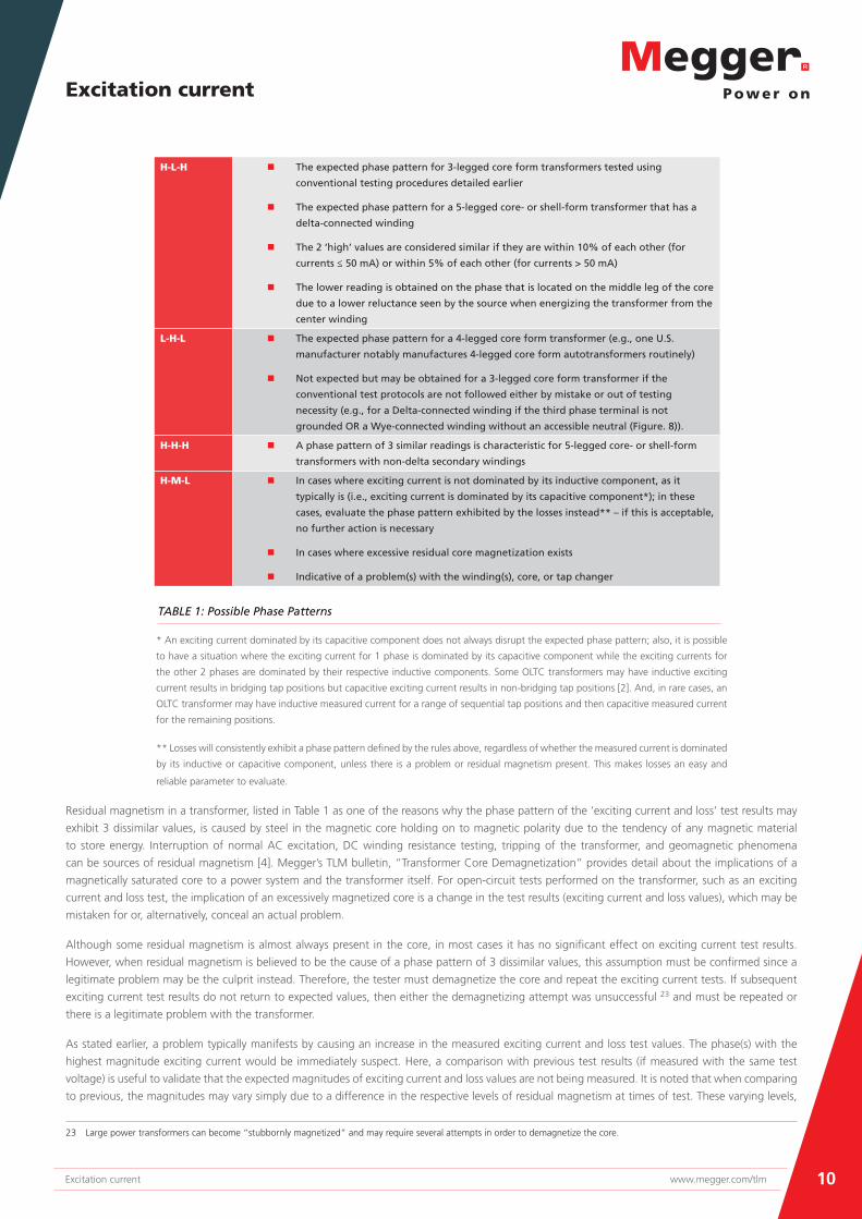
An H-L-H phase pattern is most commonplace. However, there are four possible phase patterns as given in Table 1:
FIGURE 9: ‘Exciting current and loss’ test results for a reactive style (on-load) tap-changing 3-phase transformer (OLTC pattern 2)
Excitation current
10Excitation current www.megger.com/tlm
H-L-H n The expected phase pattern for 3-legged core form transformers tested using
conventional testing procedures detailed earlier
n The expected phase pattern for a 5-legged core- or shell-form transformer that has a
delta-connected winding
n The 2 ‘high’ values are considered similar if they are within 10% of each other (for
currents ≤ 50 mA) or within 5% of each other (for currents > 50 mA)
n The lower reading is obtained on the phase that is located on the middle leg of the core
due to a lower reluctance seen by the source when energizing the transformer from the
center winding
L-H-L n The expected phase pattern for a 4-legged core form transformer (e.g., one U.S.
manufacturer notably manufactures 4-legged core form autotransformers routinely)
n Not expected but may be obtained for a 3-legged core form transformer if the
conventional test protocols are not followed either by mistake or out of testing
necessity (e.g., for a Delta-connected winding if the third phase terminal is not
grounded OR a Wye-connected winding without an accessible neutral (Figure. 8)).
H-H-H n A phase pattern of 3 similar readings is characteristic for 5-legged core- or shell-form
transformers with non-delta secondary windings
H-M-L n In cases where exciting current is not dominated by its inductive component, as it
typically is (i.e., exciting current is dominated by its capacitive component*); in these
cases, evaluate the phase pattern exhibited by the losses instead** – if this is acceptable,
no further action is necessary
n In cases where excessive residual core magnetization exists
n Indicative of a problem(s) with the winding(s), core, or tap changer
TABLE 1: Possible Phase Patterns
* An exciting current dominated by its capacitive component does not always disrupt the expected phase pattern; also, it is possible
to have a situation where the exciting current for 1 phase is dominated by its capacitive component while the exciting currents for
the other 2 phases are dominated by their respective inductive components. Some OLTC transformers may have inductive exciting
current results in bridging tap positions but capacitive exciting current results in non-bridging tap positions [2]. And, in rare cases, an
OLTC transformer may have inductive measured current for a range of sequential tap positions and then capacitive measured current
for the remaining positions.
** Losses will consistently exhibit a phase pattern defined by the rules above, regardless of whether the measured current is dominated
by its inductive or capacitive component, unless there is a problem or residual magnetism present. This makes losses an easy and
reliable parameter to evaluate.
Residual magnetism in a transformer, listed in Table 1 as one of the reasons why the phase pattern of the ‘exciting current and loss’ test results may
exhibit 3 dissimilar values, is caused by steel in the magnetic core holding on to magnetic polarity due to the tendency of any magnetic material
to store energy. Interruption of normal AC excitation, DC winding resistance testing, tripping of the transformer, and geomagnetic phenomena
can be sources of residual magnetism [4]. Megger’s TLM bulletin, “Transformer Core Demagnetization” provides detail about the implications of a
magnetically saturated core to a power system and the transformer itself. For open-circuit tests performed on the transformer, such as an exciting
current and loss test, the implication of an excessively magnetized core is a change in the test results (exciting current and loss values), which may be
mistaken for or, alternatively, conceal an actual problem.
Although some residual magnetism is almost always present in the core, in most cases it has no significant effect on exciting current test results.
However, when residual magnetism is believed to be the cause of a phase pattern of 3 dissimilar values, this assumption must be confirmed since a
legitimate problem may be the culprit instead. Therefore, the tester must demagnetize the core and repeat the exciting current tests. If subsequent
exciting current test results do not return to expected values, then either the demagnetizing attempt was unsuccessful 23 and must be repeated or
there is a legitimate problem with the transformer.
As stated earlier, a problem typically manifests by causing an increase in the measured exciting current and loss test values. The phase(s) with the
highest magnitude exciting current would be immediately suspect. Here, a comparison with previous test results (if measured with the same test
voltage) is useful to validate that the expected magnitudes of exciting current and loss values are not being measured. It is noted that when comparing
to previous, the magnitudes may vary simply due to a difference in the respective levels of residual magnetism at times of test. These varying levels,
23 Large power transformers can become “stubbornly magnetized” and may require several attempts in order to demagnetize the core.

Excitation current
11Excitation current www.megger.com/tlm
while not excessive to cause a disruption in the phase patterns, may still cause the magnitudes of exciting current and loss to “dance” between tests.
As long as the magnitude of change between tests is consistent between phases, the noted change in test results from previous should not be taken
as a positive indication of a problem.
If the exciting current and loss phase pattern exhibited at the Neutral position is normal (e.g., H-L-H) while disruption of the phase pattern occurs at
some other position(s) of the OLTC, this suggests that the abnormal results are not being caused by the core or the main winding. Generally, regardless
of the type and design of OLTC present, the neutral position of the tap changer is a reflection of the core and main windings only.
OLTC Pattern Analysis
The OLTC pattern is the pattern exhibited by the exciting current (or loss) test results measured within a single phase as the on-load tap changer
(OLTC) is moved through each of its positions. For example, the OLTC pattern exhibited by the exciting current measurements in Phase 1 of Figure 9
is OLTC pattern 2, whereby test results for all non-bridging tap positions are equal (e.g., approximately 21.56 mA) and test results for all bridging tap
positions are equal (e.g., approx. 70.4 mA) with the exception of one (or several) position. In this example, the one ‘unique’ measurement occurs on
OLTC position 11R (32.9 mA), highlighted in grey in Figure 9, indicating that the OLTC’s preventive autotransformer bridges less turns (by design) in
this position than in the other bridging positions.
Since the exciting current measurements in Phase 1 of Figure 9 exhibit OLTC pattern 2, the exciting current measurements in Phase 2 and 3 must also
exhibit OLTC pattern 2. Moreover, the losses measured in Phase 1 must exhibit OLTC pattern 2, as must the losses measured in Phase 2 and 3. A quick
evaluation reveals that this is indeed the case.
There are 12 possible LTC patterns that depend on the design of the OLTC [2]. Eleven of these patterns represent normal variations that may be seen
in test results with reactive type OLTCs. A reactive type OLTC, the predominant and widespread utilization of which is in North America, uses a reactor
(e.g., a preventive autotransformer (PA) and/or a series transformer/autotransformer) as the impedance to limit circulating current when the tap
changer is engaged, e.g., in a bridging24 (i.e., odd) tap position. In reactive style OLTCs, bridging positions are ‘operational’25 positions. A common
OLTC pattern for reactive style OLTCs is provided in Figure 10, wherein the current and loss test results for all non-bridging (i.e., even) tap positions
are similar and the current and loss test results for all bridging tap positions are similar.
In resistive type OLTCs, which are in widest use worldwide, there are no ‘operational’ bridging positions. A resistive type OLTC never spends more than
approximately 40 – 60 ms in a bridging state so when performing a static measurement, such as exciting current and loss tests, bridging components
such as diverter resistors are not included in the test circuit26. Figure 11 provides an OLTC pattern representative of a resistive type OLTC.
Single Phase Transformer
Exciting current test results for a single phase transformer should be compared to previous test results. The test voltage must be the same for the
comparison to be valid. Barring the availability of previous test results, exciting current test results may also be compared to those of a similar/sister
transformer. The results should compare closely.
24 A bridging position is a position whereby two consecutive taps are selected at the same time and some form of impedance, resistive or reactive, is present to limit resulting
circulating current.
25 An operational position infers that the transformer may remain in service at this tap position indefinitely, if desired
26 This is why dynamic resistance measurements on resistive type OLTCs, which test its bridging components, is strongly recommended.
FIGURE 10: OLTC Pattern 1 FIGURE 11: OLTC Pattern 7

Excitation current
12Excitation current www.megger.com/tlm
Closing Words
The exciting current test is a recommended routine field test particularly as it exhibits capabilities of identifying emerging problems such as partial
turn-to-turn short circuits and a wide range of tap changer problems. An exciting current test is an important commissioning test, noting cases in
which this test has singularly identified core construction/assembly problems in new transformers during their acceptance. It is also recommended to
perform this test before and after performing tap changer maintenance; not only does the testing provide a check for the integrity of the work done,
it has also proven useful to make sure that the tap changer has been reconnected properly.
There are several alternate field diagnostic tests that overlap the exciting current test in their diagnostic capabilities but none that completely mirror it.
A look (below) at these complementary/alternate tests underscores the broad diagnostic capabilities of an exciting current and loss test:
n Magnetic balance test – provides assessment of the magnetic circuit
n Transformer turns ratio (TTR) – sensitive to main and tap winding problems
n Sweep frequency response analysis (SFRA) – reveals core problems and winding problems
n DC winding resistance tests – reveals winding problems, is the preferred test for checking for open-circuited
conditions, and is a good tool for diagnosing tap changer problems
n (OLTC) Dynamic (resistance) measurements – sensitive to problems revealed during the operation of an OLTC
tap changer and therefore includes an assessment of bridging components of resistive-type OLTCs (which is
not provided in an exciting current test, TTR, or DC winding resistance test)
n Dissolved gas analysis (DGA) – some winding and core problems result in gassing in the transformer oil. DGA
on OLTC samples is also a tap changer diagnostic tool in use.

Excitation current
13
TLM9_Bulletin_ExcitationCurrent_en_V01i - www.megger.com/tlm
The word ‘Megger’ is a registered trademark
TLM Bulletins - Copyright © Megger Limited, Dover, CT17 9EN, UK
References
[1] Poulin, B. “Exciting Current of Power Transformers,” Proceedings of the Sixty-
Third Annual International Conference of Doble Clients, 1996, Sec. 8-9.
[2] Duplessis, J. “A Further Study of Exciting Current Patterns,” Proceedings of
the Sixty-Ninth Annual International Conference of Doble Clients, 2002.
[3] Duplessis, J. “Assessing the Magnetic Circuit of a
Transformer,” PowerPoint presentation, 2003.
[4] Megger Transformer Life Management (TLM) Bulletin,
“Transformer Core Demagnetization”, March 2017.