transducer electronic datasheet manual and programming guide · 2019-08-20 · teds manual and...
TRANSCRIPT

Sensor Solutions SourceLoad · Torque · Pressure · Multi-Axis · Calibration · Instruments · Software
www.futek.com
TEDSTransducer Electronic DatasheetManual and Programming Guide
TEDS Manual and Programming Guide 2
Sensor Solution SourceLoad · Torque · Pressure · Multi-Axis · Calibration · Instruments · Software
www.futek.com
Table of Contents
What is TEDS? . . . . . . . . . . . . . . . . . . . . . . . . . . . . . . . . . . . . . . . . . . . . . . . . . . . . . . . . . . . . . . . . . . . . . . . . . . . . . . . . . . . . . . . . . .3
FUTEK Sensors and Solutions that are compatible with TEDS . . . . . . . . . . . . . . . . . . . . . . . . . . . . . . . . . . . . . . . . . . . . . . . . . . . .3
How is TEDS Implemented? . . . . . . . . . . . . . . . . . . . . . . . . . . . . . . . . . . . . . . . . . . . . . . . . . . . . . . . . . . . . . . . . . . . . . . . . . . . . . . .4
How to Program TEDS . . . . . . . . . . . . . . . . . . . . . . . . . . . . . . . . . . . . . . . . . . . . . . . . . . . . . . . . . . . . . . . . . . . . . . . . . . . . . . . . . . .5
TEDS Layout . . . . . . . . . . . . . . . . . . . . . . . . . . . . . . . . . . . . . . . . . . . . . . . . . . . . . . . . . . . . . . . . . . . . . . . . . . . . . . . . . . . . . . . . . .10
TEDS EEPROM Chip . . . . . . . . . . . . . . . . . . . . . . . . . . . . . . . . . . . . . . . . . . . . . . . . . . . . . . . . . . . . . . . . . . . . . . . . . . . . . . . . . . . .15
TEDS Manual and Programming Guide 3
Sensor Solution SourceLoad · Torque · Pressure · Multi-Axis · Calibration · Instruments · Software
www.futek.com
What is TEDS?
FUTEK Sensors and Solutions that are compatible with TEDS
TEDS stands for Transducer Electronic Data Sheet . It is an EEPROM device embedded in the sensor or sensor’s connector that contains calibration information such as serial number, calibration dates, and other calibration factors .
TEDS was introduced as IEEE P1451 .4 in 1997 and established the concept of “smart transducers .” These chips store important calibration data that facilitate communications between sensors and their instruments, greatly reducing the calibration and setup work that the user must perform .
It is a convenient technology that allows users to bypass the tedious process of calibrating a sensor with an instrument . This avoids potential confusion, saves time and energy, and makes the sensor a true “plug and play” experience .
ADVANTAGES OF A SYSTEM WITH TEDS
• TEDS streamlines the setup of a sensor with an instrument by allowing you to bypass complicated calibration steps . This gives you a ready-to-go, plug-and-play system and greatly diminishes the opportunity for scaling & calibration errors .
• TEDS facilitates multiple sensors for one instrument, making it cost effective, easy to troubleshoot, and simple to operate .
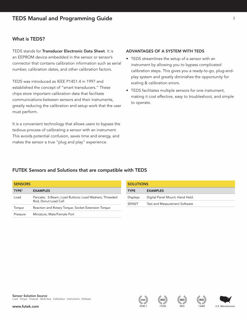
SENSORS
TYPE1 EXAMPLES
Load Pancake; S-Beam; Load Buttons; Load Washers; Threaded Rod, Donut Load Cell
Torque Reaction and Rotary Torque; Socket Extension Torque
Pressure Miniature; Male/Female Port
SOLUTIONS
TYPE EXAMPLES
Displays Digital Panel Mount; Hand Held .
SENSIT Test and Measurement Software
TEDS Manual and Programming Guide 4
Sensor Solution SourceLoad · Torque · Pressure · Multi-Axis · Calibration · Instruments · Software
www.futek.com
How is TEDS Implemented?
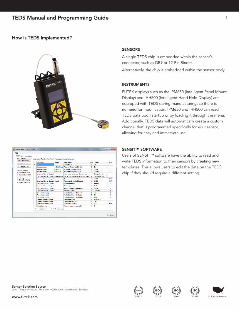
SENSORS
A single TEDS chip is embedded within the sensor’s connector, such as DB9 or 12-Pin Binder .
Alternatively, the chip is embedded within the sensor body .
INSTRUMENTS
FUTEK displays such as the IPM650 (Intelligent Panel Mount Display) and IHH500 (Intelligent Hand Held Display) are equipped with TEDS during manufacturing, so there is no need for modification . IPM650 and IHH500 can read TEDS data upon startup or by loading it through the menu . Additionally, TEDS data will automatically create a custom channel that is programmed specifically for your sensor, allowing for easy and immediate use .
SENSIT™ SOFTWARE
Users of SENSIT™ software have the ability to read and write TEDS information to their sensors by creating new templates . This allows users to edit the data on the TEDS chip if they should require a different setting .
TEDS Manual and Programming Guide 5
Sensor Solution SourceLoad · Torque · Pressure · Multi-Axis · Calibration · Instruments · Software
www.futek.com
How to Program TEDS
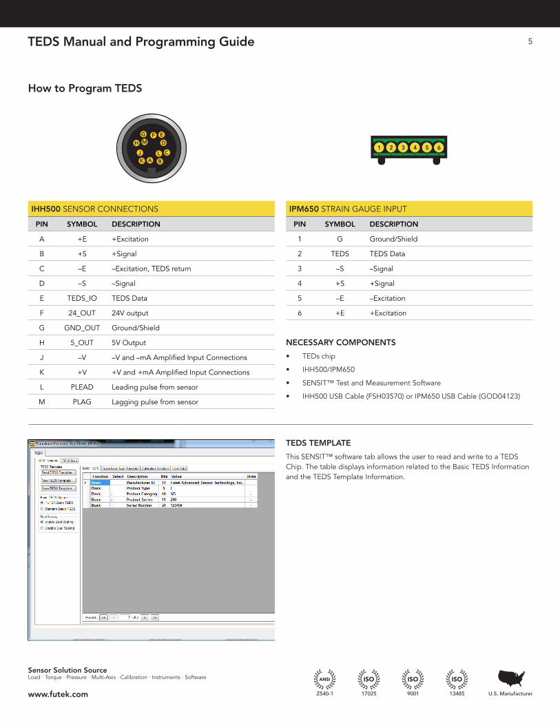
IHH500 SENSOR CONNECTIONS
PIN SYMBOL DESCRIPTION
A +E +Excitation
B +S +Signal
C –E –Excitation, TEDS return
D –S –Signal
E TEDS_IO TEDS Data
F 24_OUT 24V output
G GND_OUT Ground/Shield
H 5_OUT 5V Output
J –V –V and –mA Amplified Input Connections
K +V +V and +mA Amplified Input Connections
L PLEAD Leading pulse from sensor
M PLAG Lagging pulse from sensor
6 7
1 3
4 52
8
34 2
3
5 16
6
7
5 4
8 1
3
2
F HG
E AK
D BJ
C
1 4
2 3
1 2
GM
F ED
CLBAK
J
H
GM
FED
C LB A K
J
H
1 2 3 4 5 6
1 2 3 4 5 6
7 8
Pin 2 Pin 12
Pin 12 Pin 1
FRONT BACKPin 11 Pin 1
Key
1 2 3 4 5 6
IPM650 STRAIN GAUGE INPUT
PIN SYMBOL DESCRIPTION
1 G Ground/Shield
2 TEDS TEDS Data
3 –S –Signal
4 +S +Signal
5 –E –Excitation
6 +E +Excitation
NECESSARY COMPONENTS
• TEDs chip
• IHH500/IPM650
• SENSIT™ Test and Measurement Software
• IHH500 USB Cable (FSH03570) or IPM650 USB Cable (GOD04123)
TEDS TEMPLATE
This SENSIT™ software tab allows the user to read and write to a TEDS Chip . The table displays information related to the Basic TEDS Information and the TEDS Template Information .
TEDS Manual and Programming Guide 6
Sensor Solution SourceLoad · Torque · Pressure · Multi-Axis · Calibration · Instruments · Software
www.futek.com
How to Program TEDS
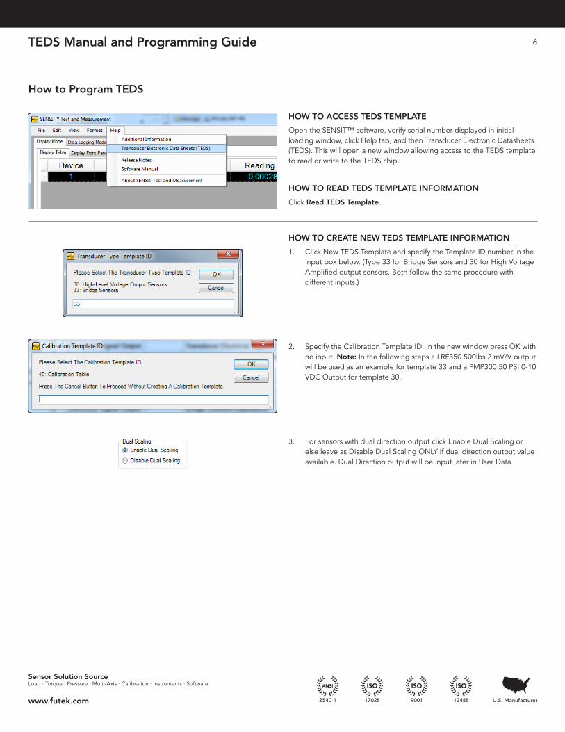
HOW TO ACCESS TEDS TEMPLATE
Open the SENSIT™ software, verify serial number displayed in initial loading window, click Help tab, and then Transducer Electronic Datasheets (TEDS) . This will open a new window allowing access to the TEDS template to read or write to the TEDS chip .
HOW TO READ TEDS TEMPLATE INFORMATION
Click Read TEDS Template .
HOW TO CREATE NEW TEDS TEMPLATE INFORMATION
1 . Click New TEDS Template and specify the Template ID number in the input box below . (Type 33 for Bridge Sensors and 30 for High Voltage Amplified output sensors . Both follow the same procedure with different inputs .)
2 . Specify the Calibration Template ID . In the new window press OK with no input . Note: In the following steps a LRF350 500lbs 2 mV/V output will be used as an example for template 33 and a PMP300 50 PSI 0-10 VDC Output for template 30 .
3 . For sensors with dual direction output click Enable Dual Scaling or else leave as Disable Dual Scaling ONLY if dual direction output value available . Dual Direction output will be input later in User Data .
TEDS Manual and Programming Guide 7
Sensor Solution SourceLoad · Torque · Pressure · Multi-Axis · Calibration · Instruments · Software
www.futek.com
How to Program TEDS
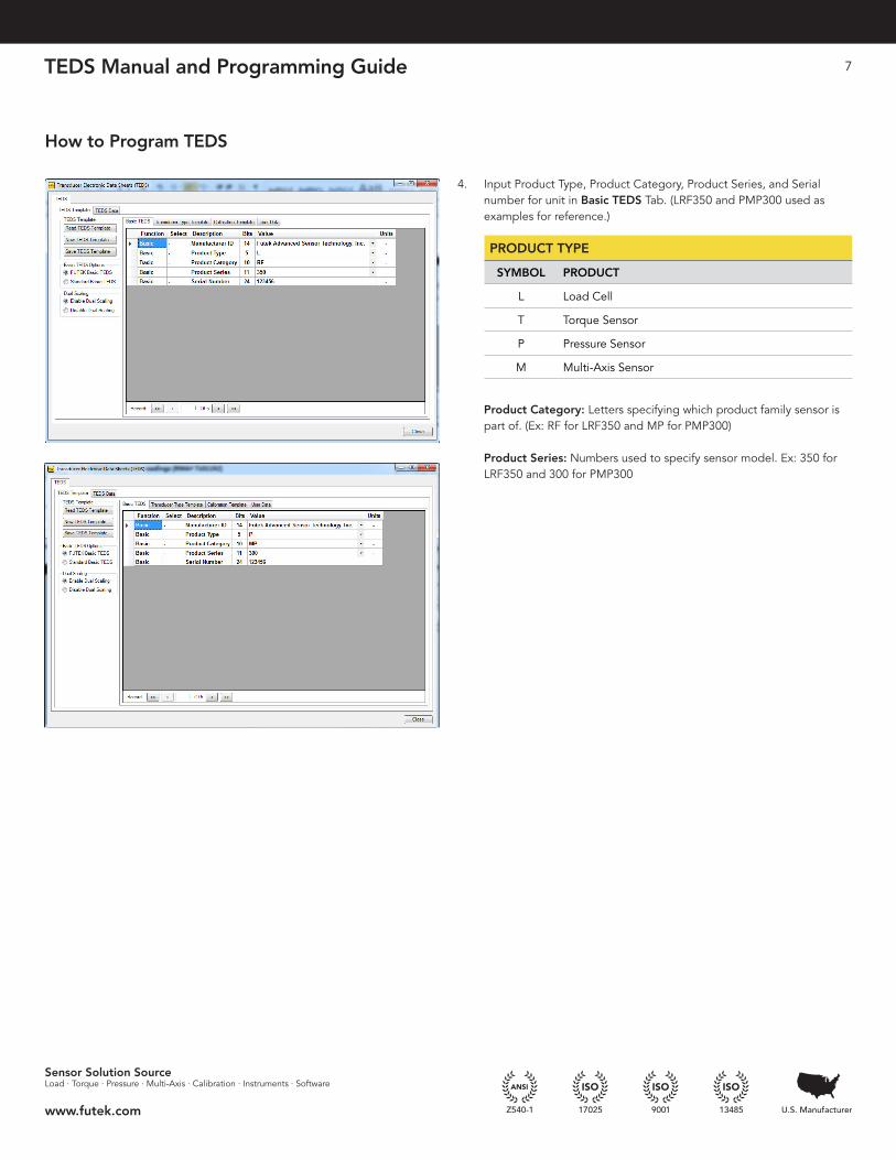
4 . Input Product Type, Product Category, Product Series, and Serial number for unit in Basic TEDS Tab . (LRF350 and PMP300 used as examples for reference .) Product Category: Letters specifying which product family sensor is part of . (Ex: RF for LRF350 and MP for PMP300) Product Series: Numbers used to specify sensor model . Ex: 350 for LRF350 and 300 for PMP300
PRODUCT TYPE
SYMBOL PRODUCT
L Load Cell
T Torque Sensor
P Pressure Sensor
M Multi-Axis Sensor
TEDS Manual and Programming Guide 8
Sensor Solution SourceLoad · Torque · Pressure · Multi-Axis · Calibration · Instruments · Software
www.futek.com
How to Program TEDS
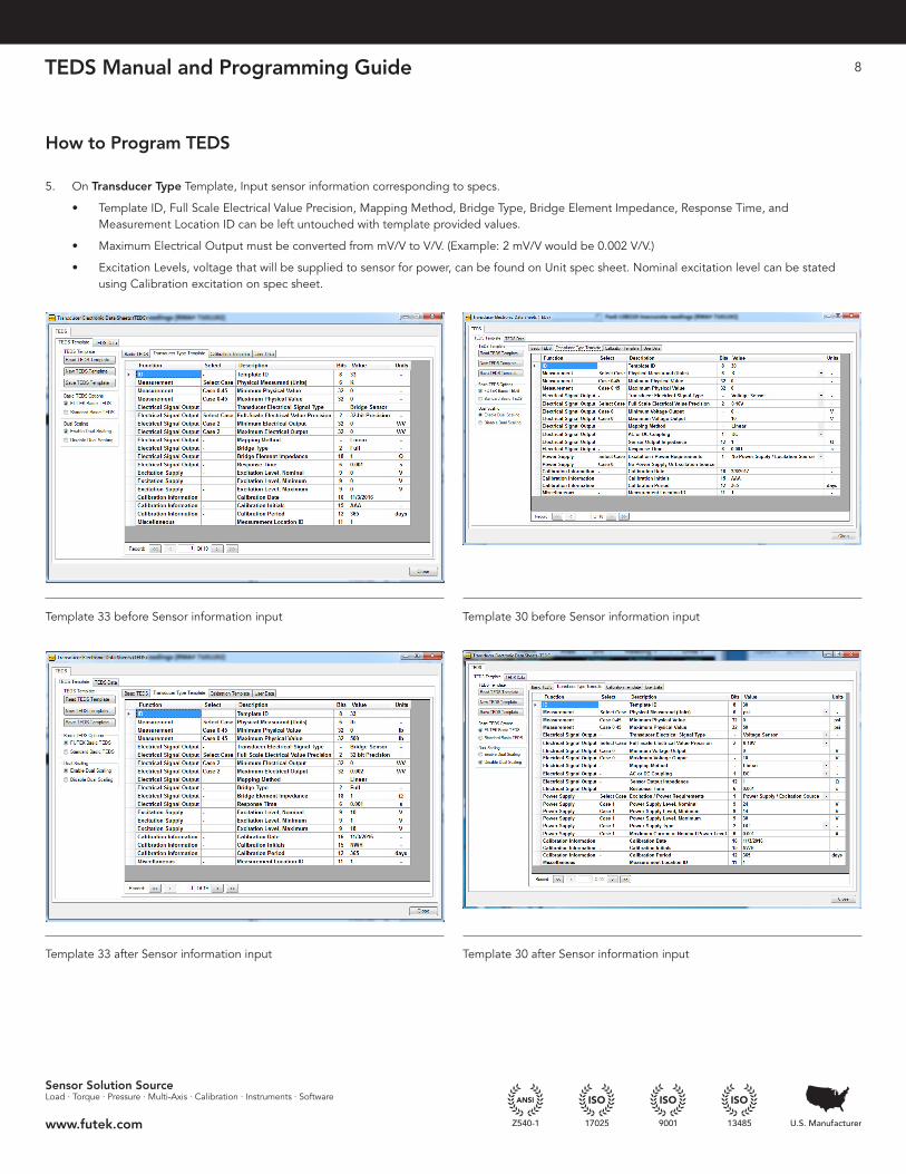
5 . On Transducer Type Template, Input sensor information corresponding to specs .
• Template ID, Full Scale Electrical Value Precision, Mapping Method, Bridge Type, Bridge Element Impedance, Response Time, and Measurement Location ID can be left untouched with template provided values .
• Maximum Electrical Output must be converted from mV/V to V/V . (Example: 2 mV/V would be 0 .002 V/V .)
• Excitation Levels, voltage that will be supplied to sensor for power, can be found on Unit spec sheet . Nominal excitation level can be stated using Calibration excitation on spec sheet .
Template 33 before Sensor information input
Template 33 after Sensor information input
Template 30 before Sensor information input
Template 30 after Sensor information input
TEDS Manual and Programming Guide 9
Sensor Solution SourceLoad · Torque · Pressure · Multi-Axis · Calibration · Instruments · Software
www.futek.com
How to Program TEDS
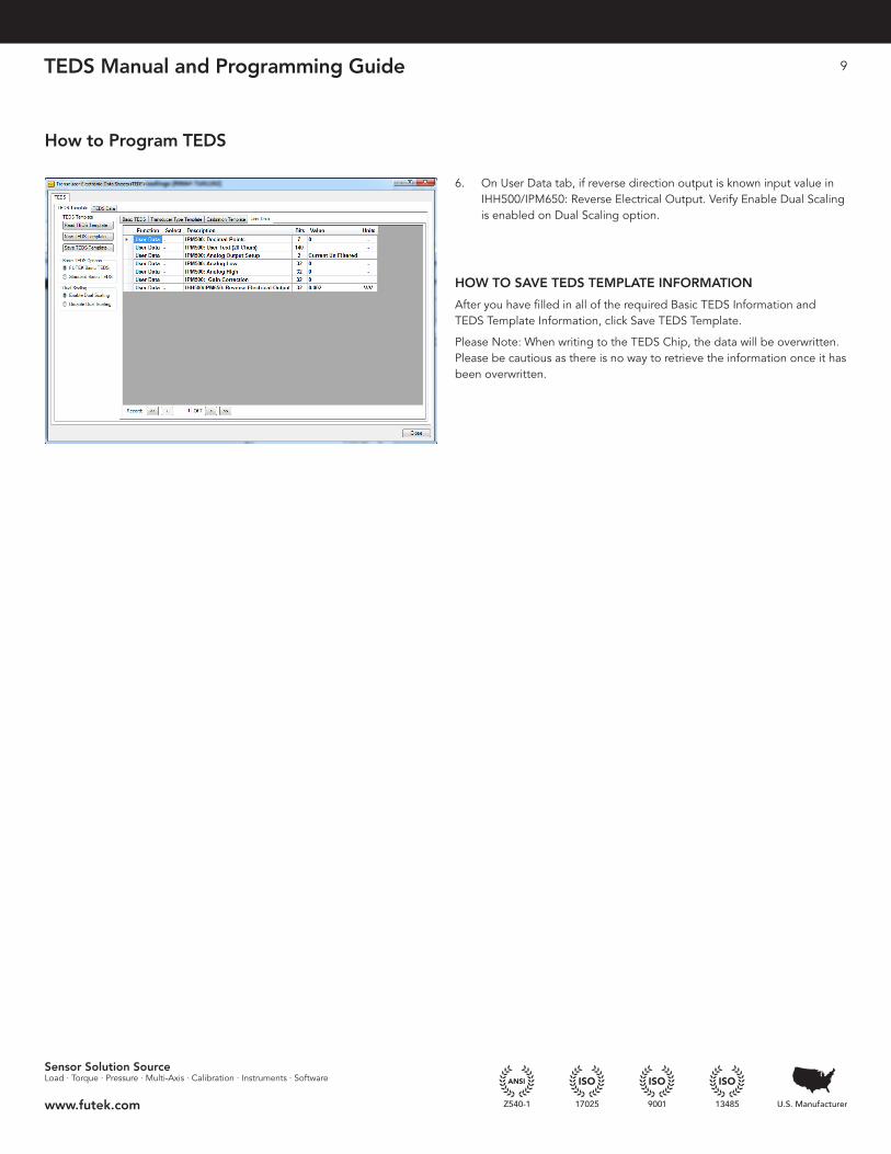
6 . On User Data tab, if reverse direction output is known input value in IHH500/IPM650: Reverse Electrical Output . Verify Enable Dual Scaling is enabled on Dual Scaling option .
HOW TO SAVE TEDS TEMPLATE INFORMATION
After you have filled in all of the required Basic TEDS Information and TEDS Template Information, click Save TEDS Template .
Please Note: When writing to the TEDS Chip, the data will be overwritten . Please be cautious as there is no way to retrieve the information once it has been overwritten .
TEDS Manual and Programming Guide 10
Sensor Solution SourceLoad · Torque · Pressure · Multi-Axis · Calibration · Instruments · Software
www.futek.com
TEDS Layout
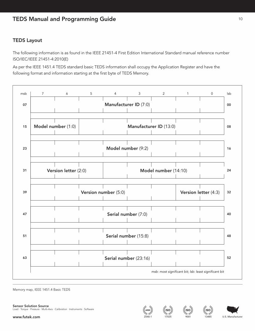
The following information is as found in the IEEE 21451-4 First Edition International Standard manual reference number ISO/IEC/IEEE 21451-4:2010(E)
As per the IEEE 1451 .4 TEDS standard basic TEDS information shall occupy the Application Register and have the following format and information starting at the first byte of TEDS Memory .
Memory map, IEEE 1451 .4 Basic TEDS
msb 7 6
Manufacturer ID (7:0)
Manufacturer ID (13:0)Model number (1:0)
Model number (9:2)
Serial number (7:0)
Serial number (15:8)
Serial number (23:16)
Model number (14:10)
Version number (5:0)
Version letter (2:0)
Version letter (4:3)
5
msb: most significant bit; lsb: least significant bit
4 3 2 1 0 lsb
07 00
15 08
23 16
31 24
39 32
47 40
51 48
63 52
TEDS Manual and Programming Guide 11
Sensor Solution SourceLoad · Torque · Pressure · Multi-Axis · Calibration · Instruments · Software
www.futek.com
HIGH-LEVEL VOLTAGE OUTPUT TEMPLATE (ID = 30) SUMMARY
FUNCTION SELECT PROPERTY/ COMMAND
DESCRIPTION ACCESS BITS DATA TYPE (AND RANGE) UNITS
ID — TEMPLATE Template ID — 8 Integer (value = 30) —
Measurement Select Case—Physical Measurand 6 Select Case —
Cases 0–45 %MinPhysVal Minimum physical value CAL 32 Single Variousa
%MaxPhysVal Maximum physical value CAL 32 Single Variousa
Electrical signal
output
— %ElecSigType Transducer Electrical Signal Type ID — Assign = 0, “Voltage Sensor” —
Select Case—Full-Scale Electrical Value Precision 2 Select Case —
Case 0 %MinElecVal Minimum voltage output CAL — Assign = 0 .0 V
%MaxElecVal Maximum voltage output CAL — Assign = 10 .0 V
Case 1 %MinElecVal Minimum voltage output CAL — Assign = -10 .0 V
%MaxElecVal Maximum voltage output CAL — Assign = 10 .0 V
Case 2 %MinElecVal Minimum voltage output CAL 11 ConRes (–20 .5 to 20 .4,
step 0 .02)
V
%MaxElecVal Maximum voltage output CAL 11 ConRes (–20 .5 to 20 .4,
step 0 .02)
V
Case 3 %MinElecVal Minimum voltage output CAL 32 Single V
%MaxElecVal Maximum voltage output CAL 32 Single V
— %MapMeth Mapping Method ID — Assign = 0, “Linear” —
— %ACDCCoupling AC or DC coupling ID 1 Enumeration: DC | AC —
— %SensorImped Sensor output impedance ID 12 ConRelRes (1 to 1 .1M, ±0 .17%) �
— %RespTime Response Time ID 6 ConRelRes (1E-6 to 7 .9, ±15%) s
Power supply
Select Case—Excitation/Power Requirements 1 Select Case —
Case 0 — No power supply or excitation
source
— — — —
Case 1 %ExciteAmplNom Power-supply level, nominal ID 9 ConRes (0 .1 to 51 .1, step 0 .1) V
%ExciteAmplMin Power-supply level, min . ID 9 ConRes (0 .1 to 51 .1, step 0 .1) V
%ExciteAmplMax Power-supply level, max ID 9 ConRes (0 .1 to 51 .1, step 0 .1) V
%ExciteType Power-supply type ID 2 Enumeration: DC | Bipolar DC | AC —
%ExciteCurrentDraw Max current at nominal power level ID 6 ConRelRes (1E-6 to 1 .6, ±13%) A
TEDS Layout
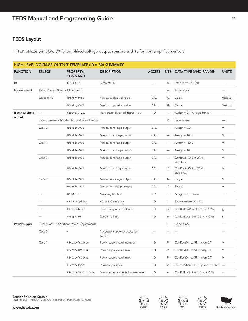
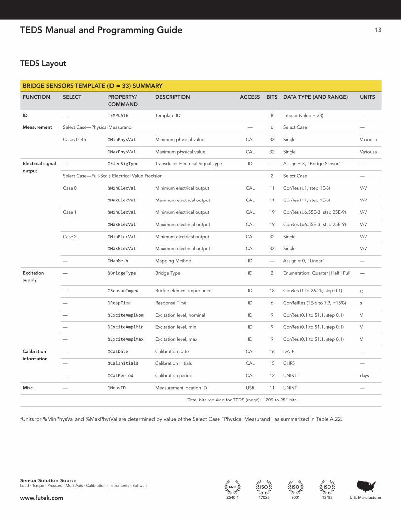
FUTEK utilizes template 30 for amplified voltage output sensors and 33 for non-amplified sensors .
TEDS Manual and Programming Guide 12
Sensor Solution SourceLoad · Torque · Pressure · Multi-Axis · Calibration · Instruments · Software
www.futek.com
HIGH-LEVEL VOLTAGE OUTPUT TEMPLATE (ID = 30) SUMMARY
FUNCTION SELECT PROPERTY/ COMMAND
DESCRIPTION ACCESS BITS DATA TYPE (AND RANGE) UNITS
Calibration
information
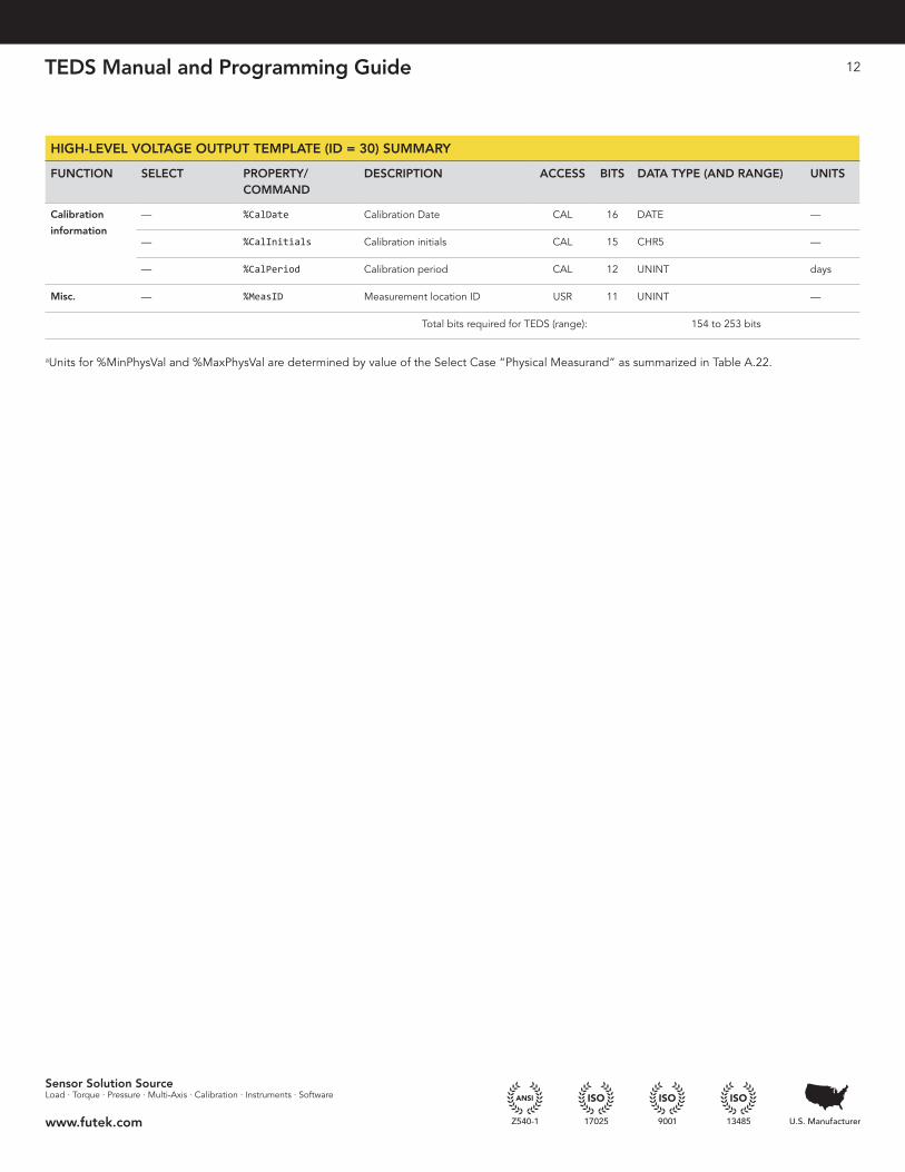
— %CalDate Calibration Date CAL 16 DATE —
— %CalInitials Calibration initials CAL 15 CHR5 —
— %CalPeriod Calibration period CAL 12 UNINT days
Misc. — %MeasID Measurement location ID USR 11 UNINT —
Total bits required for TEDS (range): 154 to 253 bits
aUnits for %MinPhysVal and %MaxPhysVal are determined by value of the Select Case “Physical Measurand” as summarized in Table A .22 .
TEDS Manual and Programming Guide 13
Sensor Solution SourceLoad · Torque · Pressure · Multi-Axis · Calibration · Instruments · Software
www.futek.com
BRIDGE SENSORS TEMPLATE (ID = 33) SUMMARY
FUNCTION SELECT PROPERTY/COMMAND
DESCRIPTION ACCESS BITS DATA TYPE (AND RANGE) UNITS
ID — TEMPLATE Template ID 8 Integer (value = 33) —
Measurement Select Case—Physical Measurand — 6 Select Case —
Cases 0–45 %MinPhysVal Minimum physical value CAL 32 Single Variousa
%MaxPhysVal Maximum physical value CAL 32 Single Variousa
Electrical signal
output
— %ElecSigType Transducer Electrical Signal Type ID — Assign = 3, “Bridge Sensor” —
Select Case—Full-Scale Electrical Value Precision 2 Select Case —
Case 0 %MinElecVal Minimum electrical output CAL 11 ConRes (±1, step 1E-3) V/V
%MaxElecVal Maximum electrical output CAL 11 ConRes (±1, step 1E-3) V/V
Case 1 %MinElecVal Minimum electrical output CAL 19 ConRes (±6 .55E-3, step 25E-9) V/V
%MaxElecVal Maximum electrical output CAL 19 ConRes (±6 .55E-3, step 25E-9) V/V
Case 2 %MinElecVal Minimum electrical output CAL 32 Single V/V
%MaxElecVal Maximum electrical output CAL 32 Single V/V
— %MapMeth Mapping Method ID — Assign = 0, “Linear” —
Excitation
supply
— %BridgeType Bridge Type ID 2 Enumeration: Quarter | Half | Full —
— %SensorImped Bridge element impedance ID 18 ConRes (1 to 26 .2k, step 0 .1) �
— %RespTime Response Time ID 6 ConRelRes (1E-6 to 7 .9, ±15%) s
— %ExciteAmplNom Excitation level, nominal ID 9 ConRes (0 .1 to 51 .1, step 0 .1) V
— %ExciteAmplMin Excitation level, min . ID 9 ConRes (0 .1 to 51 .1, step 0 .1) V
— %ExciteAmplMax Excitation level, max ID 9 ConRes (0 .1 to 51 .1, step 0 .1) V
Calibration
information
— %CalDate Calibration Date CAL 16 DATE —
— %CalInitials Calibration initials CAL 15 CHR5 —
— %CalPeriod Calibration period CAL 12 UNINT days
Misc. — %MeasID Measurement location ID USR 11 UNINT —
Total bits required for TEDS (range): 209 to 251 bits
aUnits for %MinPhysVal and %MaxPhysVal are determined by value of the Select Case “Physical Measurand” as summarized in Table A .22 .
TEDS Layout
TEDS Manual and Programming Guide 14
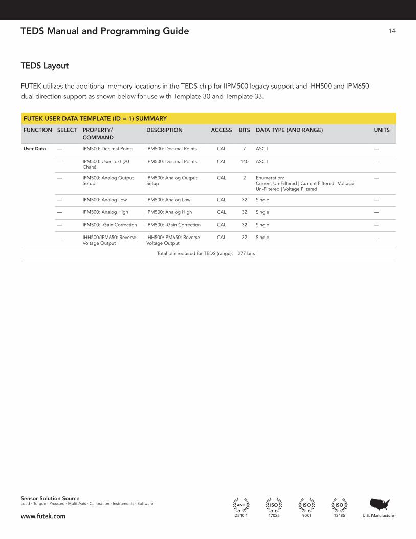
TEDS Layout
FUTEK utilizes the additional memory locations in the TEDS chip for IIPM500 legacy support and IHH500 and IPM650 dual direction support as shown below for use with Template 30 and Template 33 .
Sensor Solution SourceLoad · Torque · Pressure · Multi-Axis · Calibration · Instruments · Software
www.futek.com
FUTEK USER DATA TEMPLATE (ID = 1) SUMMARY
FUNCTION SELECT PROPERTY/ COMMAND
DESCRIPTION ACCESS BITS DATA TYPE (AND RANGE) UNITS
User Data — IPM500: Decimal Points IPM500: Decimal Points CAL 7 ASCII —
— IPM500: User Text (20 Chars)
IPM500: Decimal Points CAL 140 ASCII —
— IPM500: Analog Output Setup
IPM500: Analog Output Setup
CAL 2 Enumeration: Current Un-Filtered | Current Filtered | Voltage Un-Filtered | Voltage Filtered
—
— IPM500: Analog Low IPM500: Analog Low CAL 32 Single —
— IPM500: Analog High IPM500: Analog High CAL 32 Single —
— IPM500: -Gain Correction IPM500: -Gain Correction CAL 32 Single —
— IHH500/IPM650: Reverse Voltage Output
IHH500/IPM650: Reverse Voltage Output
CAL 32 Single —
Total bits required for TEDS (range): 277 bits
TEDS Manual and Programming Guide 15
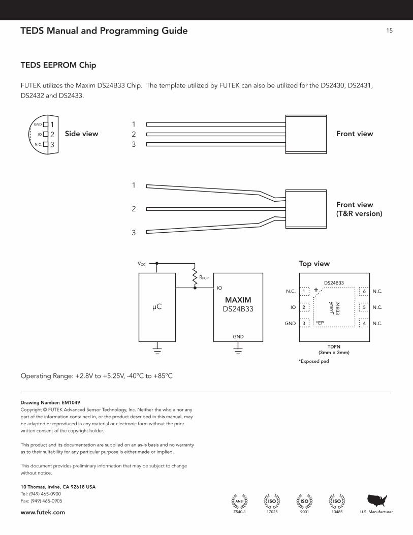
TEDS EEPROM Chip
FUTEK utilizes the Maxim DS24B33 Chip . The template utilized by FUTEK can also be utilized for the DS2430, DS2431, DS2432 and DS2433 .
Operating Range: +2 .8V to +5 .25V, -40°C to +85°C
Drawing Number: EM1049Copyright © FUTEK Advanced Sensor Technology, Inc . Neither the whole nor any part of the information contained in, or the product described in this manual, may be adapted or reproduced in any material or electronic form without the prior written consent of the copyright holder .
This product and its documentation are supplied on an as-is basis and no warranty as to their suitability for any particular purpose is either made or implied .
This document provides preliminary information that may be subject to change without notice .
10 Thomas, Irvine, CA 92618 USATel: (949) 465-0900Fax: (949) 465-0905
www.futek.com
Front viewSide view
Top view
123
1
2
3
Front view(T&R version)
123
GND
IO
N.C.
GND
DS24B33
TDFN(3mm × 3mm)
IO
VCC
µC
RPUP
MAXIMDS24B33
+
24B33
ymrrF
*EP
1
2
3
6
5
4
N.C.
N.C.
N.C.
N.C.
IO
GND
*Exposed pad