trans-tibial prosthetics - chrc...
TRANSCRIPT

Tome 2
( Alignment & Fitting )
Trans-tibialProsthetics
Course Work Manual
ICRC
( INTERNATIONAL COMMITTEE OF THE RED CROSS )

Aknowledgements
Substantial parts of the information and reference material provided in This Technical Manualfor Lower Limb Prosthetics has been compiled from various medical and university sources.Without their long practice, know-how and extensive publications, this manual would simplynot exist. We would like to mention in particular:
Course Work Manual, Carson Harte and Anne Henriksen, National School of Prostheticsand Orthotics from Phnom Penh, Cambodia:
- Partial foot prosthetics
- Ankle disarticulation prosthetics
- Below knee prosthetics
- Knee disarticulation prosthetics
- Above knee prosthetics
- Hip disarticulation prosthetics.
Clinical aspects of Lower extremity prosthetics, Trans-tibial, Symes and Partial footamputations, The Canadian Association of Prosthetists and Orthotists.
Traité d’Anatomie Artistique, Dr. Paul Richer, Inter livres.
Lower Limb Prosthetics, 1990 revision, New York University Medical Centre.
Lower Limb Prosthetics, 1990 revision Prosthetics and Orthotics, New York UniversityPost Graduate Medical School.

1
TTTTTrrrrrans-tibial prans-tibial prans-tibial prans-tibial prans-tibial prosthetic - Tosthetic - Tosthetic - Tosthetic - Tosthetic - Tome 2ome 2ome 2ome 2ome 2
Trans-tibial Prosthetic-Tome 2
INDEX
Section Pages
1 Below Knee Prosthetic Components 2
2 Normal Gait 15
3 Below Knee Amputee Gait Deviations 25
4 Fabrication of Socket & The Alignment 36
5 Alignments 38
6 Below Knee Prosthetic Check-out 52
7 Post Fitting Prosthetic Problems 55
Annexes
8 Cuff Suspension 62
9 Locating Mechanical Knee Joint 66
10 BK Alignment Coupling 74

2
TTTTTrrrrrans-tibial prans-tibial prans-tibial prans-tibial prans-tibial prosthetic - Tosthetic - Tosthetic - Tosthetic - Tosthetic - Tome 2ome 2ome 2ome 2ome 2
SECTION - 1
BELOW KNEE PROSTHETIC
COMPONENTS
3
TTTTTrrrrrans-tibial prans-tibial prans-tibial prans-tibial prans-tibial prosthetic - Tosthetic - Tosthetic - Tosthetic - Tosthetic - Tome 2ome 2ome 2ome 2ome 2
BELOW KNEE PROSTHETIC COMPONENTS
Introduction.
The BK Prosthesis has four major componentsa) Socketb) Suspensionc) The shank.D) Foot and ankle.
When the prosthetist is selecting the right components the overall state of the pa-tient must be considered. For example a man who works in a rice field should notbe given a leg with a soft cosmetic. He needs a water resistant leg.
Sockets.
The socket is designed to transmit the patients weight comfortably through the legto the ground. The current accepted design for the PTB was developed in 1958 inCalifornia. Slight variations exist but the principal remains the same.
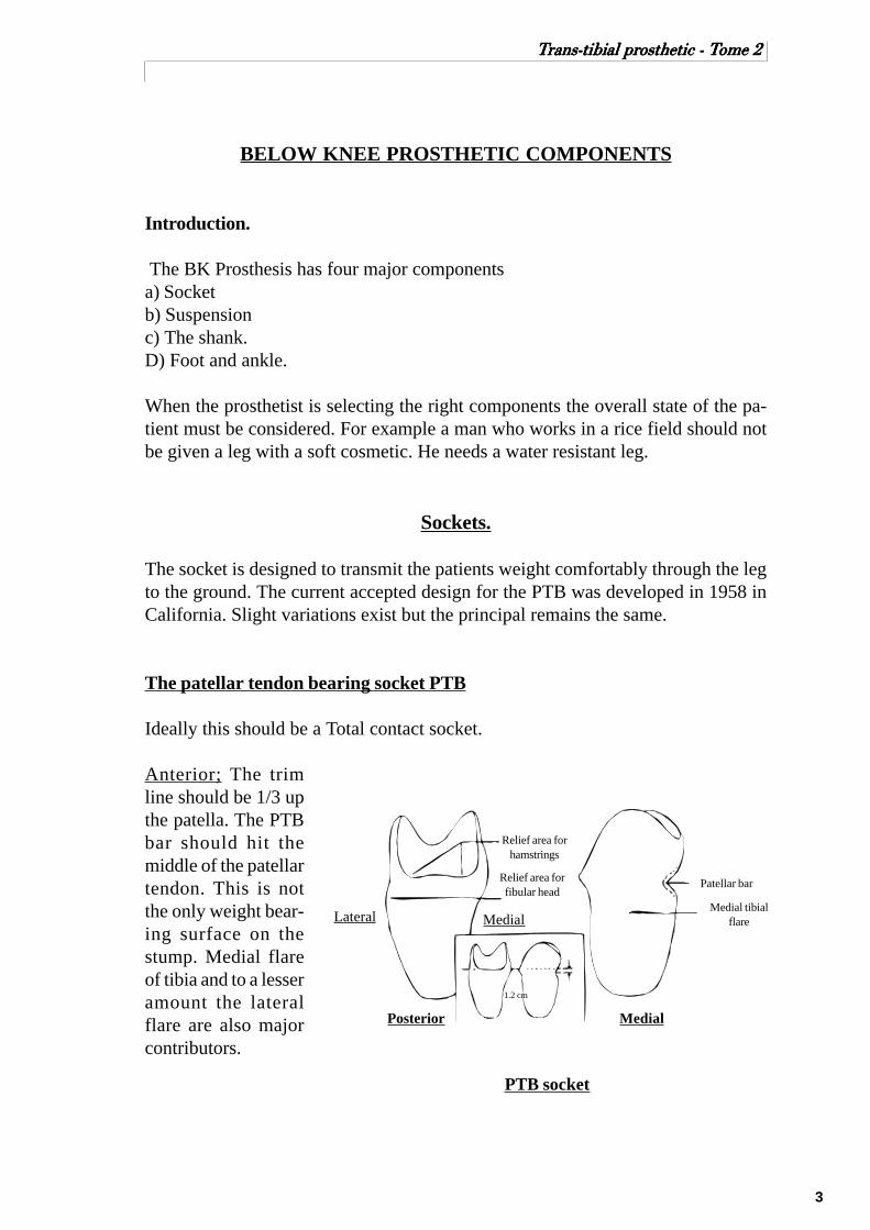
The patellar tendon bearing socket PTB
Ideally this should be a Total contact socket.
Anterior; The trimline should be 1/3 upthe patella. The PTBbar should hit themiddle of the patellartendon. This is notthe only weight bear-ing surface on thestump. Medial flareof tibia and to a lesseramount the lateralflare are also majorcontributors.
1.2 cm
PTB socket
Relief area forfibular head
Relief area forhamstrings
Patellar bar
Posterior Medial
Lateral MedialMedial tibial
flare

4
TTTTTrrrrrans-tibial prans-tibial prans-tibial prans-tibial prans-tibial prosthetic - Tosthetic - Tosthetic - Tosthetic - Tosthetic - Tome 2ome 2ome 2ome 2ome 2
Medial Lateral; The trim line is about the level of the adductor tubercle. The lateralwall has a pocket for the head of fibula. The lateral wall presses on the fibula and solocates the medial tibial flare on its shelf.
Posterior; The posterior wall is flared at the top to allow for the hamstrings. Theback wall presses in on the popliteal fossa to push the stump forward and locate thePTB.
The PTB socket can be made with a hard or soft liner.The PTB socket can be used for all BK stumps except for those with specific patho-logical conditions that would point to the use of a socket variation. Very shortstumps and severely flexed stumps can cause problems.The hard or soft socket is a matter of patient tolerance, material availability, andhygienic facility.
Suspension
Supracondylar cuff suspension.
Several versions for the cuff have been designed. The cuff can be made of leather orwebbing with or without elastic. It fastens tight above the condyles. The attachmentpoints are arranged posterior andabove the joint line so that as theknee is flexed the down strapsshorten. (See annexe for the fabri-cation and installation of a cuff sus-pension strap.)
The major disadvantage of the cuffis the impossibility of not havingpistonning of the prosthesis. It alsodoes impinge on the circulation. Itcannot be used in cases of exces-sive scarring or joint instability.The chief advantage, for the am-putees, is that it does give them afeeling of security.
Supracondylar cuff
Medial Anterior
5
TTTTTrrrrrans-tibial prans-tibial prans-tibial prans-tibial prans-tibial prosthetic - Tosthetic - Tosthetic - Tosthetic - Tosthetic - Tome 2ome 2ome 2ome 2ome 2
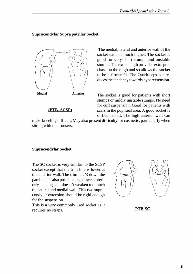
Supracondylar Supra patellar Socket
The medial, lateral and anterior wall of thesocket extends much higher. The socket isgood for very short stumps and unstablestumps. The extra length provides extra pur-chase on the thigh and so allows the socketto be a firmer fit. The Quadriceps bar re-duces the tendency towards hyperextension.
The socket is good for patients with shortstumps or mildly unstable stumps. No needfor cuff suspension. Good for patients withscars in the popliteal area. A good socket isdifficult to fit. The high anterior wall can
make kneeling difficult. May also present difficulty for cosmetic, particularly whensitting with the trousers.
Supracondylar Socket
The SC socket is very similar to the SCSPsocket except that the trim line is lower atthe anterior wall. The trim is 2/3 down thepatella. It is also possible to go lower anteri-orly, as long as it doesn’t weaken too muchthe lateral and medial wall. This two supra-condylar extension should be rigid enoughfor the suspension.This is a very commonly used socket as itrequires no straps. PTB-SC
Medial Anterior
Quadriceps bar
(PTB- SCSP)

6
TTTTTrrrrrans-tibial prans-tibial prans-tibial prans-tibial prans-tibial prosthetic - Tosthetic - Tosthetic - Tosthetic - Tosthetic - Tome 2ome 2ome 2ome 2ome 2
Joints and Thigh Corset.
The thigh corset is generally made of leather but sometimes can be made of thinplastic. It extends distally to just above the patella and at the back 3 or 4 cm abovethis line. When the patient sits the corset must be postero proximally high enoughto not pinch the thigh. The corset is trimmed a few centimetres below the groin. It isattached to the socket by a pair of external knee joints, usually metal and singleaxis. The joints are attached on the medial and lateral sides of the socket at theposition shown in the diagram. A back check strap is also fitted to stop the jointsbefore being overloaded in extension. This reduces wear and tear.
In the past because BK sockets fitted so badly the Thigh Corset was also used tocarry the patients weight. Today the sockets are much better and so the corset isused only in cases where the knee joint is unstable or damaged. Thigh corsets arebad for circulation and cause thigh muscle atrophy. Also, the amputee wearing athigh corset does loose the reflex of controlling the knee when walking. Thighcorset can also be used to off-load the stump when the stump is badly scarred orpainful.Thigh corset are bulky, heavier and non cosmetically. Therefore they must be usedonly when strictly necessary.
Adductor Tubercle
Joint centre
Medial Tibial
Plateau
Thigh Corset

7
TTTTTrrrrrans-tibial prans-tibial prans-tibial prans-tibial prans-tibial prosthetic - Tosthetic - Tosthetic - Tosthetic - Tosthetic - Tome 2ome 2ome 2ome 2ome 2
Hip belt suspension with fork strap
Hip belt suspension with fork strap isperhaps one of the most effective, yetunpopular, suspension methods withmost patients. It consists of a webbinghip belt, elastic at front, attached to thefork strap on the prosthesis. The studlocation can be the same as describedfor the cuff suspension, but it can alsobe more anteriorly. The fork strap canalso be attached to the supracondylarstrap and most often must be part of theexternal hinges and thigh corset.
Advantages:1) excellent suspension for vascularamputees;2) non-restrictive;3) versatile and simple;4) does not limit trim line of socket;5) totally relaxed at sitting position.
Disadvantages:1) unpopular with most amputeesbecause it is uncomfortable;2) somewhat difficult to don.
5 cm webbingwaist belt
5 cm elasticwebbing
Fork strap
Studlocation
Even for the PTB-SC with a wedge, when you are fitting a patient with a very shortstump, the hip belt suspension with fork strap can be very helpful, relieving some ofthe weight while walking, and reducing the distal pressure on the distal end of thestump.

8
TTTTTrrrrrans-tibial prans-tibial prans-tibial prans-tibial prans-tibial prosthetic - Tosthetic - Tosthetic - Tosthetic - Tosthetic - Tome 2ome 2ome 2ome 2ome 2
Sleeve suspension
The sleeve can be made out of latex, neoprene (spenco),silicone or elastic fabric. Except for the fabric sleeve,they are all air tight. The sleeve is pulled over the proxi-mal portion of the prosthesis, using skin contact proxi-mal on the thigh of the amputee to obtain an air seal.The prosthesis is suspended by the somewhat stretchedfabric and the negative pressure produced.
Advantages:1) excellent suspension due to the near suction effect;2) no circulatory restriction;3) prevention of tissue bulge at the posterior of the knee;4) good cosmetic.
Disadvantages:1) excessive heat causing perspiration and sometimedermatic problem ;2) difficult to don;3) fragile;4) amputee cannot kneel.
Latexsleeve
Airseal
Stumpsock
Proximalbrim
Suction suspension (Negative pressure suspension NPS)
Many attempts were made in the pass, to use negative pressure as a means of sus-pension for trans tibial prosthesis, without too much success. Prosthetists were try-ing to use the same principle of NPS with a valve like for the above knee amputee.But recently, with the use of silicone or gel insert, it has been successful enough tobe used on a regular basis by many prosthetist. At the distal end of the siliconeinsert, a pin is attached.
When the patient is donning his liner, a total contact air tight fit happens betweenthe stump and the liner. Then when the patient inserts the stump into the socket, thepin slides into a locking mechanism in the bottom of the socket. The locking mecha-nism holds the liner which holds to the stump.
The combination of silicone or gel insert with the suction suspension make it ex-tremely comfortable while offering optimum suspension. It does eliminate the prob-lems of bulging, pressing, cutting the blood circulation, atrophying and so on.
Desavantages:1) more expensive then others;2) fragile to use and require change;3) need very good care in daily use;4) very warm to wear.

9
TTTTTrrrrrans-tibial prans-tibial prans-tibial prans-tibial prans-tibial prosthetic - Tosthetic - Tosthetic - Tosthetic - Tosthetic - Tome 2ome 2ome 2ome 2ome 2
Prosthetic Shanks
Introduction.
The function of the shank is:1/ To hold the foot and socket in the right position.2/ To transfer the load from the socket to the foot.3/ To provide Cosmesis.The shank can be said to be endoskeletal or exoskeletal. The endoskeletal systemhas his skeleton (the structure that carries the load) inside, just like the humanbeing. The exoskeletal has the loading structure outside, like the lobster. The out-side shell has the function of been both the skeleton and the cosmetic at the sametime.
Exoskeletal Shanks.
The major materials used are GRP (glass reinforced plastic), aluminium or poly-propylene. It can be hollowed or filled inside with wood, foam or other material.
Alignment is carried out first and then the alignment jig is removed and the shank isbuilt up. The process of removing the alignment device is called Transfer. Therelationship between foot and socket must be retained.
Advantages.
Strength, durability, cheap, easyto clean, and can be set up to suitthe level of activity.
Disadvantages.
Alignment cannot be easily ad-justed, sockets cannot easily bechanged, and the cosmetic may bepoorer.
Exoskeletal shank

10
TTTTTrrrrrans-tibial prans-tibial prans-tibial prans-tibial prans-tibial prosthetic - Tosthetic - Tosthetic - Tosthetic - Tosthetic - Tome 2ome 2ome 2ome 2ome 2
Endoskeletal Shanks.
A tube of metal or plastic connecting the socket to the foot and ankle. All stressespass down this tube and not through the cosmetic covers. Cosmetic shape is givenby the addition of a soft cover.Endoskeletal Systems are usually called MODULAR . This means that it is madeup of several parts that can be assembled, disassembled and interchanged.
Alignment devices are part of the structure of the leg. After alignment is completedthe device is ”locked” so the alignment cannot change.There are two major types of alignment device.
1/ Tilt/ Shift.In this type the alignment can be changed as a tilt or a shift from the one alignmentdevice. The major limbs to use that system is Blatchford Endolite and ICRC.
2/ Tilt/ Tilt. In this system the alignment ent can only be changed using a series ofscrews to change the angle of the socket. Shifts are achieved using a tilt at thesocket and an opposite tilt at the foot end.

11
TTTTTrrrrrans-tibial prans-tibial prans-tibial prans-tibial prans-tibial prosthetic - Tosthetic - Tosthetic - Tosthetic - Tosthetic - Tome 2ome 2ome 2ome 2ome 2
Prosthetic Feet
The prosthetic foot must be cosmetic and functional. It must behave as much likethe real foot as possible. There are many designs of foot. They can be simple inaction or very complicated.
SACH (Solid ankle cushioned heel) Foot.
The most common foot in the world. It functions well, can be light weight andrather strong. It has no moving parts and given the right conditions, it can be longlasting.
The shock absorption at heel strike is carried out by the heel cushion which com-presses and softens the action. At push off the foot’s springy toe section gives thepush off action.
Foot action.1) Plantar flexion is achieved by compression of the heel wedge.2) Dorsiflexion is not permitted except at the springy toe section.3) Medial / lateral forces are absorbed by the soft soul .
The SACH foot is an excellent foot. Cosmesis is excellent because there is no anklemovement. The normal SACH foot is used in normal length BK patients. A lowlevel SACH, also named Syme foot, is available for patients with long stumps orAnkle disarticulation.
Wood keel
Rubber footHeel cushion
External keel SACH foot
Heel cushion
Aluminium keelBelting
Syme’s SACH foot
Foam rubber

12
TTTTTrrrrrans-tibial prans-tibial prans-tibial prans-tibial prans-tibial prosthetic - Tosthetic - Tosthetic - Tosthetic - Tosthetic - Tome 2ome 2ome 2ome 2ome 2
Single Axis Foot
This is a much more old fashioned design. The action of the natural ankle is copiedby an ankle joint . The joint is made of metal. The action of the foot is quite naturalexcept that there is no inversion-eversion movement. Heel strike and shock absorp-tion are the job of the heel rubber. The spring of toe off is the job of the toes rubber.The Plantar flexion bumper is responsible for making the roll over mid stance moresmooth. Because of the metal joint at the ankle, the foot is quite heavy and alsowears out quickly. It is not a good foot for use in dirty or wet conditions. Cosmeticis poor because the movement at the ankle means that a gap is seen between the footand the shank.
Foam rubber
Metal singleaxis joint
Dorsiflexion stopPlantar flexionbumper Wood keel

13
TTTTTrrrrrans-tibial prans-tibial prans-tibial prans-tibial prans-tibial prosthetic - Tosthetic - Tosthetic - Tosthetic - Tosthetic - Tome 2ome 2ome 2ome 2ome 2
Multi axis feet
Multi axis feet suggest that the foot can move around in many directions. The Multiaxis foot can move easily in plantar flexion, dorsiflexion, pronation/supination andin rotation. The firmness of the resistance to movement can be suited to the patientby selecting the right firmness of rubber bumper. The motion is controlled by arubber ring around a ball joint. As the foot moves the ring is compressed. It pro-vides a very natural foot action but has reduced standing stability. The rubber bufferring wears away quickly so the foot is not very good in wet or dusty conditions.
14
TTTTTrrrrrans-tibial prans-tibial prans-tibial prans-tibial prans-tibial prosthetic - Tosthetic - Tosthetic - Tosthetic - Tosthetic - Tome 2ome 2ome 2ome 2ome 2
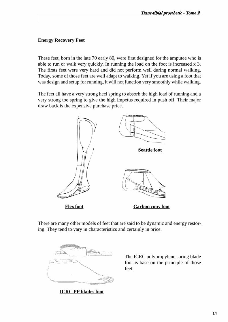
Energy Recovery Feet
These feet, born in the late 70 early 80, were first designed for the amputee who isable to run or walk very quickly. In running the load on the foot is increased x 3.The firsts feet were very hard and did not perform well during normal walking.Today, some of those feet are well adapt to walking. Yet if you are using a foot thatwas design and setup for running, it will not function very smoothly while walking.
The feet all have a very strong heel spring to absorb the high load of running and avery strong toe spring to give the high impetus required in push off. Their majordraw back is the expensive purchase price.
There are many other models of feet that are said to be dynamic and energy restor-ing. They tend to vary in characteristics and certainly in price.
Flex foot
Seattle foot
Carbon copy foot
ICRC PP blades foot
The ICRC polypropylene spring bladefoot is base on the principle of thosefeet.

15
TTTTTrrrrrans-tibial prans-tibial prans-tibial prans-tibial prans-tibial prosthetic - Tosthetic - Tosthetic - Tosthetic - Tosthetic - Tome 2ome 2ome 2ome 2ome 2
SECTION - 2
NORMAL GAIT

16
TTTTTrrrrrans-tibial prans-tibial prans-tibial prans-tibial prans-tibial prosthetic - Tosthetic - Tosthetic - Tosthetic - Tosthetic - Tome 2ome 2ome 2ome 2ome 2
NORMAL GAIT
Introduction
To understand the problems involved in amputee gait, it is first necessary tocomprehend normal human gait.
Normal gait, has been described as a series of rhythmical, alternating movements ofthe limbs and trunk which results in the forward progression of the centre of gravity.
Centre of gravity.
The centre of gravity is the representative point on the body on which the force ofgravity acts. This is generally found to be in the midline of the body lying slightlyanterior to the second sacral vertebra.
Characteristics of normal gait.
Human gait is usually described in terms of the various components of the gait cycle.
Gait cycle.
One gait cycle begin with the heel contact and end with the heel contact of the sameleg.
The gait cycle is divided into two major phases - stance phase and swing phase.In one gait cycle, the average relationship between stance and swing is 60% to 40%respectively.
Gait cycle.
P ercen t o f cy c le
S tan ce p h ase S
0 1 0 2 0 3 0 4 0 5 0 6 0 7 0
H ee l C o n ta c t
To e-O ff

17
TTTTTrrrrrans-tibial prans-tibial prans-tibial prans-tibial prans-tibial prosthetic - Tosthetic - Tosthetic - Tosthetic - Tosthetic - Tome 2ome 2ome 2ome 2ome 2
Swing phase is the period when the foot is not touching the ground.
Stance phase is defined by the period in which the foot is touching the ground.
Swing Phase
Stance Phase
Acceleration Mid swing Deceleration
HC FF MSP HO TOShock
absorp-tion
Midstance Push-off
18
TTTTTrrrrrans-tibial prans-tibial prans-tibial prans-tibial prans-tibial prosthetic - Tosthetic - Tosthetic - Tosthetic - Tosthetic - Tome 2ome 2ome 2ome 2ome 2
Stance phase
Stance phase may be divided into intervals designated by the terms shock absorp-tion (weight acceptance), midstance, and push-off.
Shock absorption.
Begin with heel contact and end with the foot fiat. This action protects the body fromthe impact.
Mid Stance Phase.
The midstance interval begin with the foot-flat position and ends with heel-off.When the greater trochanter is in vortical alignment with the vertical bisector ofthe foot, as viewed in the sagittal plane (from the side).Foot flat to heel off.
Push off phase.
From heel off to toe offThis pushes the body forward
The stance phase is also known to be subdivided into five discrete events which arethe following:heel contact, foot-flat, midstance point, heel-off, and toe-off.
Heel contact
The point at which the heel first touches the ground.
Foot flat.
When the forefoot touches the ground.
Mid Stance
The point at which the heels are side by side.
Heel off.
The time when the heel of the foot starts to leave the ground.
Toes off.
The point at which the toes leave the ground.

19
TTTTTrrrrrans-tibial prans-tibial prans-tibial prans-tibial prans-tibial prosthetic - Tosthetic - Tosthetic - Tosthetic - Tosthetic - Tome 2ome 2ome 2ome 2ome 2
Swing phase
Swing phase may be divided into three intervals designated by the terms accelera-tion, mid swing, and deceleration. Each of these subdivisions constitutes approxi-mately one-third of swing phase.
Acceleration Phase.
The toes leave the floor and the leg picks up speed as it catches up and passes thebody.
Mid swing.
The heels pass each other.
Deceleration.
After mid swing the leg slows down to a stop just before heel strike.
Double support.
The brief period of time between stance phase and swing phase, when both feet aresimultaneously in contact with the floor.As the speed of walking increases, double support becomes shorter and shorter untilit finally disappears. The absence of a period of double support distinguishesrunning from walking. Running is defined as having no double support.
In opposition to double support, single support refers to the period when only onelimb is in contact with the floor.
Timing
The relative amounts of time spent during each phase of the gait cycle at usualwalking speed are:1. Stance Phase - 60 per cent of the cycle2. Swing phase - 40 per cent of the cycle3. Double Support - 10 to 20 per cent of the cycle.
With increased walking speed there is a relative increase in time spent in swingphase, and at slower speed a relative decrease.

20
TTTTTrrrrrans-tibial prans-tibial prans-tibial prans-tibial prans-tibial prosthetic - Tosthetic - Tosthetic - Tosthetic - Tosthetic - Tome 2ome 2ome 2ome 2ome 2
Path of the Centre of Gravity
The laws of mechanics make it clear that the least amount of energy is requiredwhen a body moves along a straight line, with the centre of gravity deviating nei-ther up and down nor side to side. Such a straight line path would be possible innormal gait if the lower limbs terminated in wheels instead of feet. Since this is notthe case, the body’s centre of gravity deviates from a straight line but, for the sakeof energy conservation, the deviation or displacement should be kept to an optimallevel. In normal gait, the centre of gravity oscillates in a rhythmic manner similar toa sinusoidal curve. This alternating displacement is normally about 5 centimetres.There is a balance between the storage of energy (potential energy) and the use ofenergy (kinetic energy).
Gait characteristics influencing the path of the C.G.
Vertical displacement
In the normal walking pattern thecentre of gravity goes through arhythmic upward and downwardmotion as it moves forward.Centre of gravity rises at Mid-Stance and falls at Doublesupport The average amount ofthis vertical displacement in theadult male is approximately 5 cm.
Lateral displacement.
The centre of gravity, as it movesforward, also oscillates from sideto side as well, swaying in thedirection of the leg that is on theground. The total amount of thisside-to-side displacement is ap-proximately 5 cm.

21
TTTTTrrrrrans-tibial prans-tibial prans-tibial prans-tibial prans-tibial prosthetic - Tosthetic - Tosthetic - Tosthetic - Tosthetic - Tome 2ome 2ome 2ome 2ome 2
Walking Base.
The width of walking base is the distancebetween the mid points of the heels. Averageof 5 to 10 cm. Since the pelvis must shifttoward the weight-bearing side to maintainstability at midstance, the normally narrowwalking base minimizes the lateral displace-ment of the centre of gravity.
Pelvic Dip.
The pelvis will drop towards the side that isin swing phase. The size of the drop is 5 de-grees. It is a normal characteristic whichserves to decrease the rise of the centre ofgravity.
Pelvic Rotation.
In addition to dipping, the pelvis rotates for-ward in the horizontal plane approximately8 degrees on the swing-phase side (4 degreeson each side of a centre line). This charac-teristic of normal gait enables a slightlylonger step length without further loweringof the centre of gravity, and thus minimizestotal vertical displacement.
Knee flexion during stance phase
Shortly after heel contact, flexion of the knee begins and continues during the earlypart of stance phase (from heel strike to mid stance) until approximately 20 degreesof flexion is reached. This characteristic of normal gait by shortening the leg a littledoes reduce effectively the upward displacement of the centre of gravity.
Cadence.
70 strides per minute is said to be normal. 130 strides per minute is the fastest we canwalk without running. Slower or faster cadences then 100 to 115 steps per minute,have a pronounced effect on the values of joint angles, externally generated forces,and muscular activity.
5-10 cm

22
TTTTTrrrrrans-tibial prans-tibial prans-tibial prans-tibial prans-tibial prosthetic - Tosthetic - Tosthetic - Tosthetic - Tosthetic - Tome 2ome 2ome 2ome 2ome 2
Ground Reaction Forces (GRF).
During the gait, there are horizontaland vertical reactions forces, calledground reaction forces (GRF), fromthe ground acting on the foot and thelimb. (If you are pushing on the floor,the floor is pushing back. This is thethird law of Newton.) To study theGRF actions on the different joints ofthe body, we observe the resultant ofthese forces at different phases of thegait. The resultant from the GRFcreates moment of force on the joints ofthe leg.
Moment of forces.
A moment can be defined as thetendency of a force to create rotationabout a point. The mathematicalformula for a moment is:
M= F X D
M moment (Newton metres)F force (Newton)D perpendicular distance fromthe force to the centre of rotation(metres)
During stance, the GRF is alwaysacting in a given direction with aspecified magnitude and at a givendistance from a joint axis. Therefore,the GRF will tend to create variousflexion or extension moments at eachjoint, depending on the position of thebody at that particular instant.
D
F

23
TTTTTrrrrrans-tibial prans-tibial prans-tibial prans-tibial prans-tibial prosthetic - Tosthetic - Tosthetic - Tosthetic - Tosthetic - Tome 2ome 2ome 2ome 2ome 2
Direction of GRF & reaction on the joints for the above:
Anterior to hip causing flexion moment.Except for “Heel strike” the GRF is posterior to knee causing flexion moment.Posterior to ankle causing plantarflexion moment.
Direction of GRF & reaction on the joints for the above:
Passes through hip joint, nomoment.Posterior to knee causing a flexionmoment.Anterior to ankle causing dorsiflex-ion moment.
Posterior to hip causing extensionmoment.Anterior to knee causing extensionmoment.Anterior to ankle causing dorsiflex-ion moment.
Heel strike Shortly after heel strike Foot flat
Mid stance Heel off

24
TTTTTrrrrrans-tibial prans-tibial prans-tibial prans-tibial prans-tibial prosthetic - Tosthetic - Tosthetic - Tosthetic - Tosthetic - Tome 2ome 2ome 2ome 2ome 2
By toe-off the reaction has lost most ofits significance as the majority ofweight is borne by the other foot.
Acceleration Mid swing Deceleration
There is no GRF during the swing phase of the leg.
Toe-off
25
TTTTTrrrrrans-tibial prans-tibial prans-tibial prans-tibial prans-tibial prosthetic - Tosthetic - Tosthetic - Tosthetic - Tosthetic - Tome 2ome 2ome 2ome 2ome 2
SECTION - 3
BELOW KNEE AMPUTEE
GAIT DEVIATIONS

26
TTTTTrrrrrans-tibial prans-tibial prans-tibial prans-tibial prans-tibial prosthetic - Tosthetic - Tosthetic - Tosthetic - Tosthetic - Tome 2ome 2ome 2ome 2ome 2
BELOW KNEE GAIT DEVIATION
Introduction
A below knee amputee supplied with a well fitted socket and an optimum alignedprosthesis should demonstrate gait patterns similar to that of a non-amputated peer.
Prior to ”optimum” alignment the prosthesis is checked at three stages –
1) Bench alignment2) Static alignment3) Dynamic alignment.
During bench alignment the technician assembles the adjustable prosthesis toinstruction which, based on experience, allow the prosthetist the maximum range ofadjustment at the subsequent fitting stage. During static alignment the prosthetistwill ensure that the amputee is comfortable and stable in the stance position. Carefulbench and static alignment will minimise the prosthetic causes of gait deviations.Dynamic alignment is performed as the amputee walks and adjustment will be madeto eliminate any gait deviations.
Acceptable Below-Knee Amputee Gait
The prosthetist must ensure that the alignment of the prosthesis is such that groundreaction force has a similar effect on the amputee’s joint movement as in the case ofnormal subjects.
Viewed from the side an amputee’s knee flexes and extends during the stance periodas the line of action of the ground reaction force passes behind and in front of theknee joint. At the instant of heel strike the knee is almost extended; full extension isnot usual due to bench alignment of the socket. During early stance between heelstrike and foot flat, the ground reaction force tends to flex the knee
This knee flexion is controlled by quadriceps activity. After mid stance the groundreaction force passes ahead of the knee tending to extend the knee. This kneeextension is controlled by the hamstrings. During late stance, immediately prior totoe off, the ground reaction force again tends to flex the knee. In an incorrectlyaligned prosthesis the distance from the line of action of the ground reaction to theknee joint may increase to the extent that the amputee may not be able to controlthe knee flexion/extension by muscle activity. Gait deviations may result.
27
TTTTTrrrrrans-tibial prans-tibial prans-tibial prans-tibial prans-tibial prosthetic - Tosthetic - Tosthetic - Tosthetic - Tosthetic - Tome 2ome 2ome 2ome 2ome 2
Careful selection and adjustment of the prosthetic foot in the shoe should ensuregood amputee gait. Careless adjustment of the prosthetic foot may result in anincreased/decreased knee moment from the ground reaction force and henceexcessive/insufficient knee flexion. Viewed from the front or rear stability at mid-stance is necessary with the foot flat on the ground. An incorrectly medial/lateralaligned prosthesis will upset the stability. The two extremes are a knee that moveslaterally at mid-stance or an abducted gait. Other features of acceptable amputee gaitare smooth rhythmic movements with even step length, step timing and arm swing.The degree of toe out on the amputated side should match that of the sound side.
Below-Knee Gait Deviations
Gait analysis consists of identifying if a gait deviation exists and determining thecause. Keep in mind that the below-knee amputee may be able to compensate andperhaps overcompensate for alignment changes.
Three major deviations may be present in a below knee amputee’s gait1) EXCESSIVE KNEE FLEXION2) INSUFFICIENT KNEE FLEXION3) LATERAL THRUST OF THE KNEE
1) Excessive knee flexion
Description: At normal walking speeds (60 to 90 metres/minute) knee flexion earlyin stance is approximately 15 to 20 degrees decreasing to approximately 40 degreesat toe-off. Knee flexion larger than these levels should be considered to be excessive.A common expression used by amputees to describe this gait deviation is that theyfeel as if they lack knee control.
When to observe: During stance phase.How to observe: View from the side.

28
TTTTTrrrrrans-tibial prans-tibial prans-tibial prans-tibial prans-tibial prosthetic - Tosthetic - Tosthetic - Tosthetic - Tosthetic - Tome 2ome 2ome 2ome 2ome 2
B) Excessive posteriordisplacement of the foot.
Excessive posterior dis-placement of the footincreases the distancebetween the line of actionof the ground reactionforce and the knee jointresulting in a larger kneeflexion moment beingapplied. Again if theamputee fails to compen-sate then excessive kneeflexion occurs during earlyand late stance. Duringstance phase the patientrolls over too fast. At latestance phase, it looks likeif the patient is falling in ahole.
Optimum
Optimum
Early stance
Late stance
Early stance
Late stance
Optimum
Optimum
A) Excessive dorsiflexionof the foot.
If the prosthetic foot is set intoo much dorsiflexion thesocket and therefore thestump are tilted forwardrelative to the foot. The kneejoint position moves for-ward relative to the support-ing ground reaction force.This results in a larger kneeflexion moment being ap-plied early and late in thestance phase. After heelstrike the patient feels pre-cipitated forward.

29
TTTTTrrrrrans-tibial prans-tibial prans-tibial prans-tibial prans-tibial prosthetic - Tosthetic - Tosthetic - Tosthetic - Tosthetic - Tome 2ome 2ome 2ome 2ome 2
C) Excessively stiff plantarflexion bumper (heel cushion of foot).
In normal locomotion during the shock absorption period the ground reaction forceapplies a plantar flexion moment to the ankle joint and a flexion moment to the knee.If the compression of the rear rubber of a foot is insufficient to simulate the correctplantarflexion during early stance, the shock of foot impact is absorbed by excessiveknee flexion during early stance. Again, the patient may seem to be precipitatedforward.
D) Excessively soft dorsiflexion bumper.
As the body’s centre of gravity passes forward over the support foot, balance ismaintained until the c of g passes ahead of the foot. If the front support from theprosthetic foot is inadequate (too soft) then the socket and hence the amputee’s c ofg will pass ahead of the support foot too quickly. There will be excessive kneeflexion at the end of stance.
E) Flexion contractures.
There are non/prosthetic causes of this gait deviation e.g. an amputee with a kneeflexion contracture from tight or contracted hamstrings will walk with an excessivedegree of knee flexion throughout stance.
F) Suspension features which prevent full knee extension.
Conception and modification of the cast for a PTB SC and a PTB SCSP can restricttoo much the extension. They create too much pressure just above the patella level,and prevent full extension of the knee. The deviation will occur throughout stance.
If you are using a suspension with a supracondylar strap, fixing the anchorage of thecuff too posterior on the socket will also limit the extension of the knee.
G) Small prosthetic foot.
If the front support section of the prosthetic foot is inadequate due to too small a footbeing selected the amputee’s c of g will move ahead of the support foot too quicklycausing excessive flexion late in stance. Just like a too soft front support of theprosthetic foot.
30
TTTTTrrrrrans-tibial prans-tibial prans-tibial prans-tibial prans-tibial prosthetic - Tosthetic - Tosthetic - Tosthetic - Tosthetic - Tome 2ome 2ome 2ome 2ome 2
2) Insufficient knee flexion.
Description: This gait deviation is the opposite of that described earlier andthe prosthetic causes tend to be the exact opposite. A common expression used bythe amputee to describe this gait is that they feel as if they are walking up a hill.
When to observe: During stance phase.How to observe: View from the side.
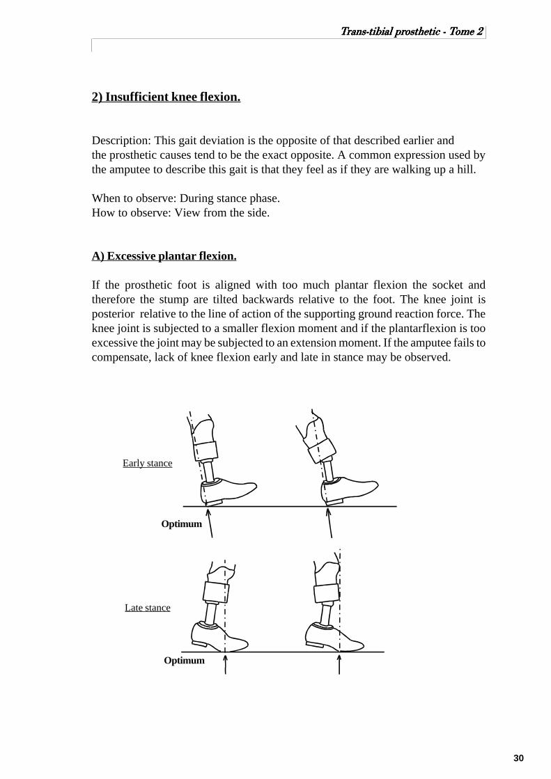
A) Excessive plantar flexion.
If the prosthetic foot is aligned with too much plantar flexion the socket andtherefore the stump are tilted backwards relative to the foot. The knee joint isposterior relative to the line of action of the supporting ground reaction force. Theknee joint is subjected to a smaller flexion moment and if the plantarflexion is tooexcessive the joint may be subjected to an extension moment. If the amputee fails tocompensate, lack of knee flexion early and late in stance may be observed.
Early stance
Late stance
Optimum
Optimum

31
TTTTTrrrrrans-tibial prans-tibial prans-tibial prans-tibial prans-tibial prosthetic - Tosthetic - Tosthetic - Tosthetic - Tosthetic - Tome 2ome 2ome 2ome 2ome 2
B) Excessive anterior displacement of the prosthetic foot.
If the foot is displaced anteriorly, the distance from the knee joint to the line ofaction of the ground reaction force reduces. The flexion moment applied to the kneereduces and if the foot is displaced anteriorly too excessively a knee extensionmoment may be applied throughout stance.
Early stance
Late stance
Optimum
Optimum

32
TTTTTrrrrrans-tibial prans-tibial prans-tibial prans-tibial prans-tibial prosthetic - Tosthetic - Tosthetic - Tosthetic - Tosthetic - Tome 2ome 2ome 2ome 2ome 2
C) Anterior-distal socket discomfort.
When the ground reaction force flexes the knee, the degree of flexion is controlledby the quadriceps resulting in stump/socket interface pressure in the anterior-distalarea. During bench alignment the socket is flexed to emphasise the patellar bar. If,as a result of incorrect cast rectification of the anterior-distal area or incorrectalignment, the pressure causes discomfort at the anterior-distal area of the stump, theamputee will compensate by adopting a gait during which the knee is not subjectedto flexion. This can be accomplished by:
-1) shortening the prosthetic step;-2) digging the heel into the ground with increased hip extensor activity;-3) leaning well forward to ensure the line of action of the ground reaction force does not pass behind the knee joint;-4) some combination of these.
D) Weakness of the quadriceps muscles.
Some below knee amputees have weak quadriceps and are unable to control kneeflexion moments. Adopting a gait, similar to that for (c), reduces or eliminate theneed for quadriceps controls since no knee flexion moment will be applied by theground reaction force during stance.
E) Habit.
Some amputees may have developed an established pattern of walking which relieson the prosthesis’ resistance to hyperextension, for example a standard P.T.B withthigh corset. When these established amputees are transferred to a supracondylar,P.T.B their usual gait will result in hyperextension of the knee. A short period of gaittraining should eliminate this gait deviation.
Likewise an amputee’s knee hyperextension may have been controlled by hisprecedent PTB SC prosthesis.
33
TTTTTrrrrrans-tibial prans-tibial prans-tibial prans-tibial prans-tibial prosthetic - Tosthetic - Tosthetic - Tosthetic - Tosthetic - Tome 2ome 2ome 2ome 2ome 2
3) Lateral thrust of the knee
Description: Lateral thrust of the knee may be described as lack of lateral kneestability during stance. The knee moves in a lateral direction on weight bearing, asthe medial socket brim presses against the stump and the lateral socket brim tendsto gap. The standard walking base is 5 to 10 cm as described in the normallocomotion section. Any prosthetic cause which results in the amputee walking witha narrower walking base will often result in lateral thrust of the knee.
When to observe: During mid stance.How to observe: View from in front behind the amputee.
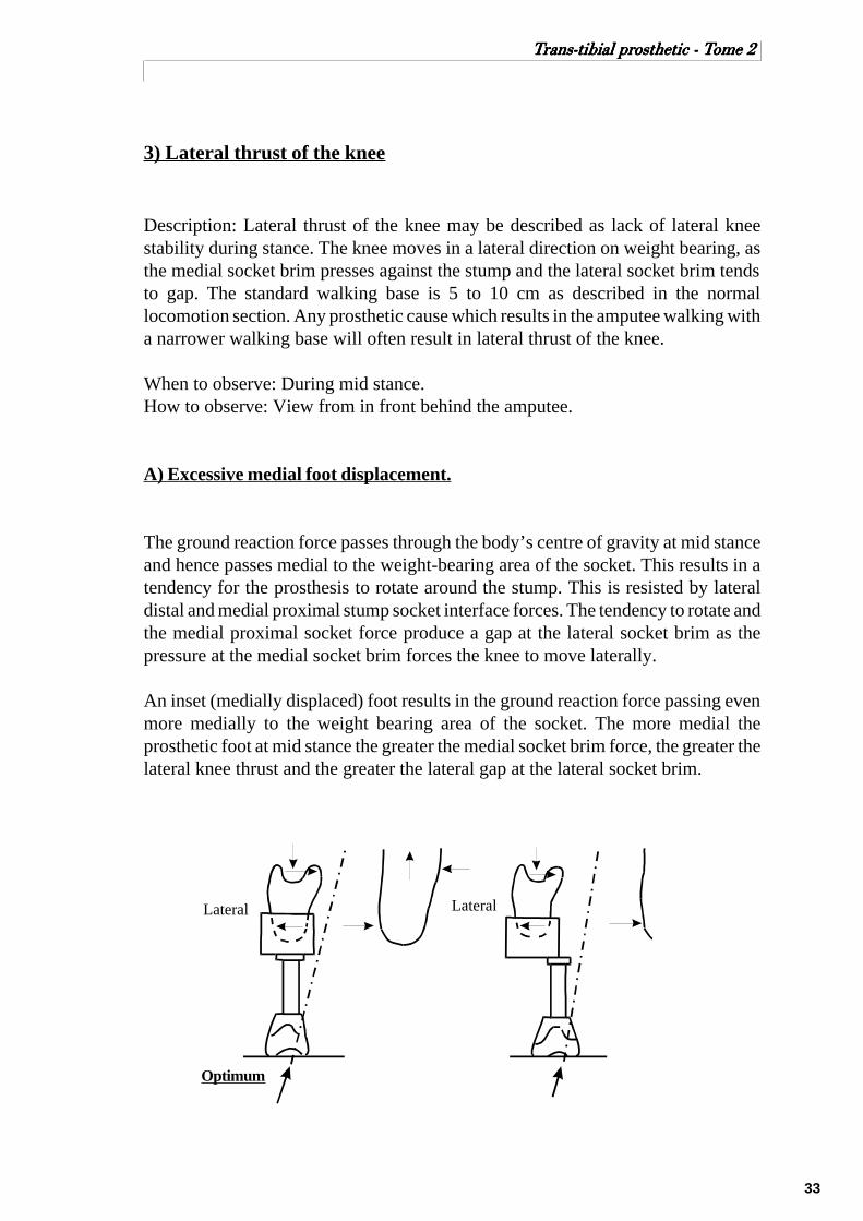
A) Excessive medial foot displacement.
The ground reaction force passes through the body’s centre of gravity at mid stanceand hence passes medial to the weight-bearing area of the socket. This results in atendency for the prosthesis to rotate around the stump. This is resisted by lateraldistal and medial proximal stump socket interface forces. The tendency to rotate andthe medial proximal socket force produce a gap at the lateral socket brim as thepressure at the medial socket brim forces the knee to move laterally.
An inset (medially displaced) foot results in the ground reaction force passing evenmore medially to the weight bearing area of the socket. The more medial theprosthetic foot at mid stance the greater the medial socket brim force, the greater thelateral knee thrust and the greater the lateral gap at the lateral socket brim.
Optimum
LateralLateral
34
TTTTTrrrrrans-tibial prans-tibial prans-tibial prans-tibial prans-tibial prosthetic - Tosthetic - Tosthetic - Tosthetic - Tosthetic - Tome 2ome 2ome 2ome 2ome 2
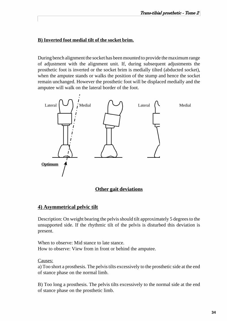
B) Inverted foot medial tilt of the socket brim.
During bench alignment the socket has been mounted to provide the maximum rangeof adjustment with the alignment unit. If, during subsequent adjustments theprosthetic foot is inverted or the socket brim is medially tilted (abducted socket),when the amputee stands or walks the position of the stump and hence the socketremain unchanged. However the prosthetic foot will be displaced medially and theamputee will walk on the lateral border of the foot.
Lateral LateralMedial Medial
Optimum
Other gait deviations
4) Asymmetrical pelvic tilt
Description: On weight bearing the pelvis should tilt approximately 5 degrees to theunsupported side. If the rhythmic tilt of the pelvis is disturbed this deviation ispresent.
When to observe: Mid stance to late stance.How to observe: View from in front or behind the amputee.
Causes:a) Too short a prosthesis. The pelvis tilts excessively to the prosthetic side at the endof stance phase on the normal limb.
B) Too long a prosthesis. The pelvis tilts excessively to the normal side at the endof stance phase on the prosthetic limb.

35
TTTTTrrrrrans-tibial prans-tibial prans-tibial prans-tibial prans-tibial prosthetic - Tosthetic - Tosthetic - Tosthetic - Tosthetic - Tome 2ome 2ome 2ome 2ome 2
5) Uneven timing.
Description: The steps are of unequal duration, usually a very short stance phase onthe prosthetic side.
When to observe: Throughout the gait cycle.How to observe: View from the side.
Causes:
A) Improperly fitting socket may cause discomfort and a desire to shorten the stancephase on the prosthetic side and an increased swing period.
B) Alignment instability.
C) The amputee may not have developed good balance.
D) Amputee’s fear and insecurity.
6) Uneven arm swinging.
Description: The arm on the prosthetic side is held close to the body.
When to observe: Throughout the gait cycle.How to observe: View from the side.
Causes:
A) Amputee may not have developed good balance.
B) Fear and insecurity accompanied by uneven timing.
C) Stump discomfort.
D) Habit pattern.
36
TTTTTrrrrrans-tibial prans-tibial prans-tibial prans-tibial prans-tibial prosthetic - Tosthetic - Tosthetic - Tosthetic - Tosthetic - Tome 2ome 2ome 2ome 2ome 2
SECTION - 4
FABRICATION OF SOCKET
AND THE ALIGNMENT

37
TTTTTrrrrrans-tibial prans-tibial prans-tibial prans-tibial prans-tibial prosthetic - Tosthetic - Tosthetic - Tosthetic - Tosthetic - Tome 2ome 2ome 2ome 2ome 2
ALIGNMENT & THE FABRICATION OF BK SOCKETALIGNMENT & THE FABRICATION OF BK SOCKETALIGNMENT & THE FABRICATION OF BK SOCKETALIGNMENT & THE FABRICATION OF BK SOCKETALIGNMENT & THE FABRICATION OF BK SOCKET
Although different materials such as aluminum, wood and leathers are still used forthe fabrication of socket, practically speaking, we could say that plastic is the mainmaterial for socket fabrication. With the plastic, there are two main approaches tosocket fabrication; they are the resin laminated sockets and the thermoplastic sheetforming socket. Generally speaking both technology use the vacuum for the form-ing of the socket. All sockets can be made with or without a liner.
Much has been written about the fabrication technologies. Therefore we shall avoidthat subject and leave the details to the instructors.
Nevertheless, there is one aspect of the fabrication which is of interest to us. It is theset up for the alignment. In the fabrication of prosthesis, two main approaches areused. One consists of adding to the socket, all components for the alignment, afterthe socket has been fabricated. Another one consist of integrating some compo-nents for the alignment in the socket fabrication process. This is the approach thatICRC is using with the polypropylene vacuum thermoforming technology. Whenthe space is available, the tibial sockets are fabricated with an adaptor for the align-ment.
Basically speaking, where this integrating alignment approach is used, we can saythat the initial alignment (bench alignment) start at the moment of socket fabrica-tion and therefore, care must be taken for positioning the adaptor at the right posi-tion. This adaptor should be placed with respect of the initial flexion (5 - 7 degreesof anterior tilt) and any so call valgum or varum of the knee. Placing the adaptor atthe proper angulation and the right position will give the prosthetist the optimumpossibility for alignment and proper fitting. On the contrary, if the alignment adap-tor is wrongly placed it will render the process of alignment pain taking and timeconsuming, Furthermore, the cosmetic of the prosthesis can be difficult to com-pleted properly later.
After the vacuum thermoforming or the lamination is complete and cooled down, thesocket is trimmed along the proximal edge and the plaster cast broken out or blownout with compressed air. The edge of the trim lines are determined according to thetype of socket and the particularities that the prosthetist wants his socket to perform.
Here you should pay attention to the angle of the cast cutter blade while cutting thesocket. If your angle is not appropriate, you will cut into the liner, making this latter,shorter than the socket.

38
TTTTTrrrrrans-tibial prans-tibial prans-tibial prans-tibial prans-tibial prosthetic - Tosthetic - Tosthetic - Tosthetic - Tosthetic - Tome 2ome 2ome 2ome 2ome 2
SECTION - 5
ALIGNMENTS

39
TTTTTrrrrrans-tibial prans-tibial prans-tibial prans-tibial prans-tibial prosthetic - Tosthetic - Tosthetic - Tosthetic - Tosthetic - Tome 2ome 2ome 2ome 2ome 2
ALIGNMENTS
Alignment may be defined as the relationship between the socket and the foot.Proper alignment and good socket fit go hand in hand; one will not do without theother. A well-fitting socket will be uncomfortable with poor alignment, and viceversa.
In the field of prosthetic, we do consider three kinds of alignments: the benchalignment (initial alignment), the static alignment and the dynamic alignment.
Bench alignment ( initial alignment) is attaching the socket, shank and foot to eachother in the proper relation, according to the measurements and the informationsrecorded during the patient assessment. This is done before fitting the prosthesisonto the patient for weight bearing.
Static alignment is the alignment done with the patient standing up and puttingweight on the prosthesis but not walking. Usually this alignment is done between theparallel bar.
Dynamic alignment is done with the patient walking, first between the parallel barthen outside of them.
The alignment can be modified under the socket or just over the foot. It can be doneby tilting (changing the angulation) or by shifting (sliding the socket or the footwithout changing the angles). Also, when you do tilt one part you usually need toshift the component to replace it at the original place. Some of the tilting requireshifting to reposition the socket at the same position in relation to the foot. Systemlike the Otto Bock pyramidal alignment device does require tilting in order to shift.
Shift &Tilt TiltShift

40
TTTTTrrrrrans-tibial prans-tibial prans-tibial prans-tibial prans-tibial prosthetic - Tosthetic - Tosthetic - Tosthetic - Tosthetic - Tome 2ome 2ome 2ome 2ome 2
When you are doing the initial alignment (bench alignment), we have a tendency oftalking about the angulation and the position of the socket. In practice we often talkof shifting or tilting the socket. This is because the foot stays put on the table whilethe socket is moving. When you are doing the static or the dynamic alignment, anychange in angulation or in shifting does reflect on the foot. This is because the stumpdoesn’t move, hence the socket is also not moving. Therefore, the foot will move.
Those two different points of view regarding the alignment tend to be confusing attimes. When we are reading the literature on the subject of alignment, are we talkingof moving the socket or the foot.
For the practical purpose, keep in mind that if you tilt or shift the socket in onedirection you are moving the foot in the opposite direction and vice versa.
41
TTTTTrrrrrans-tibial prans-tibial prans-tibial prans-tibial prans-tibial prosthetic - Tosthetic - Tosthetic - Tosthetic - Tosthetic - Tome 2ome 2ome 2ome 2ome 2
Bench alignment (initial alignment)
Tilting (angulation) of the socket.
The socket and foot are attached to each other so that the socket is flexedapproximately 5 to 7 degrees. In order to expose appropriate areas of the anteriorstump surface to weight - bearing forces and to reduce forces tending to hyperextendthe knee during the latter half of stance phase.
For very short stumps the flexion should be increased up till approximately 15 deg.
If the knee has flexum (flexion contracture) the socket should be initially set up withthat amount of flexion. Some prosthetists would say to add 5° of flexion to the initialflexum.
The socket is placed in adduction or abduction to correspond with the valgum orvarum of the knee, which has been recorded during patient assessment. Usually, ashort stump will seem to be in valgum while a long stump may look like being invarum. This is because of the “S” shape of the tibia and the bony structure of theresidual bones.
A good reference mark for the mediolateral tilt is the PTB indent. Assuming the castwas modified properly, you look from behind and put the PTB indent horizontal.This should place the socket with the right mediolateral tilt.
Shifting (position) of the socket.
A plumb line from the antero - posterior centre of the socket will fall approximately1/3 along the foot (schemas p.43), depending on the length of the keel in the foot.
A plumb line from the centre of the posterior wall will fall approximately 1 cmlateral to the centre of the heel.
The toes of the foot are turned out approximately 5 degrees with respect to the lineof progression of the socket. Generally speaking, the edge of the foot give the lineof progression. The line of the middle of the foot with the line from the edge of thefoot give a 5° angle.
The height is taken from the lower edge of the PTB indent.

42
TTTTTrrrrrans-tibial prans-tibial prans-tibial prans-tibial prans-tibial prosthetic - Tosthetic - Tosthetic - Tosthetic - Tosthetic - Tome 2ome 2ome 2ome 2ome 2
The pylon is an excellent visual reference point to see if the prosthesis is leaning toomuch in a direction or another. Therefore, the pylon should be as vertical aspossible, to facilitate the observation of the shifting during walking.
The prosthetic foot should be of proper size, ajusted for the heel heights of the shoeworn by the amputee, and fitting snugly into the shoe.The following 2 reference lines must be drawn on the socket:
Antero – posterior referenceline.- Connecting the mid pointbetween the patellar tendon andthe posterior wall with the centrepoint near the distal end.
Posterior reference line.
- Connecting the centrepoint at the posterior walland the centre point nearthe posterior distal end.
When you are lookingfrom the posterior, thePTB indent should behorizontal.
Posterior view
Centre of theposterior wall
Lateral view
Antero – posteriorcentre of socket
1/21/2

43
TTTTTrrrrrans-tibial prans-tibial prans-tibial prans-tibial prans-tibial prosthetic - Tosthetic - Tosthetic - Tosthetic - Tosthetic - Tome 2ome 2ome 2ome 2ome 2
Generally speaking, the edge of the foot gives the line of progression. The line ofthe middle of the foot with the line from the edge of the foot give a 5° angle.
Remember, this initial alignment should give the prosthetist enough free way tomake all the changes needed during the static and the dynamic alignment withouttoo much pain taking. This way we maximise our chances to obtain the optimumfinal alignment for the patient.
1 /3 2 /3
AnteriorPosterior
5°-7° of flexion
Lateral view
PTB indent shouldbe horizontal.
1 cm
MedialLateral
Posterior view
Top view
Midline of the foot
Line of progressionEdge of the foot
Lateral
Medial

44
TTTTTrrrrrans-tibial prans-tibial prans-tibial prans-tibial prans-tibial prosthetic - Tosthetic - Tosthetic - Tosthetic - Tosthetic - Tome 2ome 2ome 2ome 2ome 2
Static alignment and fitting
Procedure
1) Review the information on the measure chart. Re check the patient and makeyourself familiar with the problems.
2) Check the prescription and see if the prosthesis you have been asked to fit is thesame.
3) Check the bench alignment and see if it is approximately correct.
4) Examine the patient’s stump carefully. Note any cuts, abrasions or damage. Thiswill help to work out if the new socket has caused any damage to the stump. Checkalso for signs of swelling.
5) Put on the normal stump socks and then try the liner. It should be a snug fit andthe stump should go all the way in without a big effort. If the fit is bad it will be”better to abandon the fitting and recast”. Before doing that check the measures onthe chart with the measures today and see if the patient has changed. If he has thenfind out why and assess the need to make a new socket.
Static alignment.
Preliminary alignment of the prosthesis is based on observation of the amputee ashe stands between the parallel bars and shift his weight to distribute it equallybetween the prosthesis and the sound leg.
1) Put the leg on the patient and assess the fit. There should be no major gaps at therim, and the patient should have no discomfort. Adjust or abandon as required.In order to proceed correctly, check the patellar pocket in order to ensure that thestump fits into the socket. The prosthetist should keep in mind that the amputee willbe expected to walk with a flexed knee, with weight borne over the middle third ofthe foot in midstance.
2) Ask the patient to stand and if he can comfortably, assess the fit and height of theleg. At this point the patient should be asked about pain. Primary patients will alwayshave a little discomfort. Make sure the patient is putting proper weight on theprosthesis and does not flex his hip.
3) The next step is to check for the correct length of the prosthesis and the toe out.This should be done with the amputee standing with equal weight on both legs andfeet approximately 10 cm apart at the heels. The toe out should be the same as thenormal leg, keeping in mind that external rotation of the amputated side from thehip is possible. Both feet should be in line, with the prosthetic foot flat on the floor.At this time, the hips should be level and the pylon tube vertical.

45
TTTTTrrrrrans-tibial prans-tibial prans-tibial prans-tibial prans-tibial prosthetic - Tosthetic - Tosthetic - Tosthetic - Tosthetic - Tome 2ome 2ome 2ome 2ome 2
For the height, you can check the levelusing three anatomical referencespoints; the iliac crest, the anterosuperior iliac spine and the posterosuperior iliac spine. The last one, thepostero superior iliac spine is theeasiest to assess with your naked eyes,without the use of any tool. Becausewhen you are checking the level of thehip, you are very close to the patient.The short distance between those twopoints fit very well in your visual rangewhen you are that close to the patient.
4) Check the initial tilt of the socket.
If the heel is off the floor, give moreflexion to the socket. If the front part ofthe foot is not touching the floor, givemore extension to the socket. To beable to well use that reference the footshould have a snug fitting into the shoe.If too much pressure on the lateralupper side of the socket, the socketmust be more abducted, (varum).If too much pressure on the medioproximal edge of the socket, adductedthe socket (valgum).
As a rule of thumb, given the patient is not over compensating and he is puttingproper weight on the prosthesis, most of the tilting adjustment of the socket can bedone during the static alignment. As for the shifting of the socket, it cannot beobserved during the static alignment, and must be handle during the dynamicalignment.
If the amputee should experience any socket discomfort at this time, have him sitdown. Remove the prosthesis and quickly check for pressure marks. Using theamputee’s remarks as guidance, look for stump sock impression marks. If pressureis in an unwanted area, lipstick can be used on the stump sock at the pressure spot.Have the amputee don the prosthesis again and bear weight on it. Remove theprosthesis. A lipstick stain should indicate the pressure area in the socket. Thesocket should then be eased out before proceeding.
Remember the patient is the most important part of the process. Always listen to hiscomments and ask his opinion. But you must also use your judgment and yourexperience to understand what the patient is trying to tell you.

46
TTTTTrrrrrans-tibial prans-tibial prans-tibial prans-tibial prans-tibial prosthetic - Tosthetic - Tosthetic - Tosthetic - Tosthetic - Tome 2ome 2ome 2ome 2ome 2
Dynamic alignment
The prosthetist should not expect a perfect gait from any amputee. Factors to con-sider include age, physical condition, joint function, length of stump, surgery, men-tal condition and skin condition.
The most desirable gait pattern is achieved when the amputee walks effortlessly inrelative comfort and with near normal appearance. The walking base should be asnarrow as possible in comparison to that of a normal person.
In a normal gait pattern, the amputee’s knee should be in about 10 to 12 degreesflexion at heel contact, with the prosthesis rotating smoothly but rapidly into fullcontact with the floor.
As anterior progression continues smoothly, the knee joint continues to extend atmidstance. At this point the foot is flat and secure on the walking surface and theknee joint is in about 5 to 7 degrees of flexion (the amount of flexion built into theprosthesis) to allow further extension of the knee from midstance to toe off. Theswing phase should be natural in appearance, with minimum piston action betweenthe residual limb and socket. (The initial flexion built into the prosthesis minimizesstrain on the hamstring tendon at the time of push off.)
The prosthetist should always listen to his patient’s feedback, but he should use hisknowledge and trained eye to make the right decisions.
1) Once the amputee has become accustomed to standing on the prosthesis andshifting his weight from leg to leg, and after static alignment has been completed,refinements can be made by observing the amputee walk. Best to walk between therails until he is confident.
2) If the alignment is not too bad allow the patient to walk for 2-3 minutes to settlein. If alignment is very wrong then adjust until it is nearly correct and then let thepatient continue walking.
3) View the patient from behind or in front, then from the side. Observe theanomalies of the walking pattern and adjust as required (following pages).
4) Have the patient walking outside the parallel bars. If he is used to walk with a caneor a crutch, please have him use it for the fitting. Once a patient is accustomed to away of doing, don’t try to change it. He will always go back to his old habits.
5) If the patient is walking with an incomprehensible pattern to you, have himwalking on his old leg, if he has one. This will tell if he has any bad gait habits orpeculiarities. Observe the action of the sound leg as well since both legs may beaffected by the same deformity. Then have him re walk with the new prosthesis.From your observations see if their is way to improve or not.

47
TTTTTrrrrrans-tibial prans-tibial prans-tibial prans-tibial prans-tibial prosthetic - Tosthetic - Tosthetic - Tosthetic - Tosthetic - Tome 2ome 2ome 2ome 2ome 2
Mediolateral alignment
1. Check toe out of prosthetic foot andline of progression. Compare withsound leg during walking.
2. Foot or sole of shoe must be flat onthe floor.
3. Check the lateral or medial shift ofsocket or other motion at the proximalborder of socket. The socket should re-main stable at midstance, equal com-pression of tissue at medial and lateralproximal brim.
Mediolateral tilt adjustment:
If the foot or the sole of the shoe is notflat on the floor during midstance, a tiltadjustment is indicated. To confirm,check the pylon tubing for vertical po-sition. If, for instance, only the lateralborder of the shoe is in contact withthe floor, the pylon tubing will, at thismoment, lean laterally. The lateralproximal brim, at this moment, willgape. The medial proximal brim mayshow excessive bulging of tissue. Theamputee may complain of pressure atthe distal cut end of the fibula shaft.
To correct:1. Lateral tilt of the socket, which will bring the medial border of the shoe to thefloor and pylon vertical. The tilt does correct the foot position but at the same timeshifts the weight line further laterally to compensate.
2. Shift socket medially. As a general rule, whenever a tilt adjustment is made,always combine it with an opposite shift.

48
TTTTTrrrrrans-tibial prans-tibial prans-tibial prans-tibial prans-tibial prosthetic - Tosthetic - Tosthetic - Tosthetic - Tosthetic - Tome 2ome 2ome 2ome 2ome 2
Mediolateral shift adjustment:
Observe and adjust the width of thewalking base.If the socket over the foot is too lateral,the foot or sole of the shoe will mostlikely be flat on the floor and the pylontubing vertical. However, the amputeemay complain of abnormal pressure atthe medial proximal brim. At the sametime, the prosthetist observes the socketin a lateral motion, causing gaping atthe lateral proximal brim.Often the patient feel insecure becauseof the narrow walking base.
To correct:1. Shift the socket medially (foot laterally). Do not tilt.
If the socket was too medial, the patient would feel secure but the walking patterncould be awkward. (The patient is walking like a duck.) This is because the footwould be too far laterally from the centre of gravity. The amputee must then bringhis c.g over the foot by tilting or shifting the hip.
Anteroposterior alignment.
Observe the amputee walking left to right. Sufficient distance from the amputee isof importance to observe fully the gait cycle and possible shortcomings.
The stance phase should be smooth and even from heel contact to toe off, voluntar-ily controlled by the amputee’s residual limb and knee. The knee should not lackstability, but at the same time, excessive effort should not be required to controlstability or to flex the knee at the end of the stance phase.
The prosthetic foot should be of proper size, exact heel heights as compared to theshoe worn by the amputee, and the heel wedge or plantar flexion bumper of theproper firmness according to the weight and function of the individual amputee.

49
TTTTTrrrrrans-tibial prans-tibial prans-tibial prans-tibial prans-tibial prosthetic - Tosthetic - Tosthetic - Tosthetic - Tosthetic - Tome 2ome 2ome 2ome 2ome 2
Anteroposterior tilt & shift adjustment
1. If at heel strike the amputee cannotcontrol knee flexion, causing rapid andpremature knee flexion, the prostheticforefoot will contact the floor surfaceprematurely. The amputee will properlycomplain of pain at the distal anterioraspect of the tibia and posterior proxi-mal brim. He feels and seems to be pre-cipitated forward immediately afterheel strike.
Cause:Anterior tilt or socket flexion is exces-sive, often also causing drop off at toeoff. Also, the socket may be displacedtoo far anteriorly.
To correct:Tilt the socket posteriorly and observe gait. Avoid doing two different adjustmentsat the same time. At midstance the foot should be in contact with the floor surface,with the knee flexed approximately 5 - 7 degrees, and the pylon tubing vertical.
2. If the knee is forced into hyperex-tension, the heel cushion is excessivelycompressed, and the pylon tubing leansposteriorly, the anterior posterior place-ment of the socket is incorrect. Theamputee may complain of extreme pres-sure at the anterior proximal brim andposterior distal aspect of the socket.
To correct:Shift the socket anteriorly over the footor make a firmer heel cushion.If the same symptoms at the socket areapparent, but the prosthetic foot is incontact with front only, the heel is offthe floor and the pylon is vertical, ananterior tilt is the indication.

50
TTTTTrrrrrans-tibial prans-tibial prans-tibial prans-tibial prans-tibial prosthetic - Tosthetic - Tosthetic - Tosthetic - Tosthetic - Tome 2ome 2ome 2ome 2ome 2
3. If, at time of toe off, a sudden dropoff takes place, giving the appearanceof the amputee walking downhill withhis prosthesis and there is excessivepressure usually at the posterior proxi-mal brim, the socket has been eitherplaced too far anteriorly, or there isexcessive anterior tilt.
To correct:1. Shift the socket posteriorly over thesupport surface of the prosthetic foot.(Centring socket at P.T level, midwaybetween heel edge and ball or foot, is agood indicator.) (1/3, 2/3)
2. Tilt socket posteriorly, and reducesocket flexion.
Once anteroposterior alignment has been completed, double check the mediolateralalignment for possible refinements. Re-check the socket fit, and the lengths of pros-thesis.
If one or any gait deviation cannot be corrected through alignment changes, regard-less of the extent of the changes, then the socket fit and support must be questioned.If so, a new socket may be the only answer.
A loose, unsupportable socket will allow the amputee s residual limb to rotate withinthe socket. This may be in the anterior posterior plane and/or the medial lateralplane.
When the alignment is correct and the patient is happy, check the stump for newdamage and then prepare the prosthesis to be finished. Check and mark the trim linesand the cosmetic measures.

51
TTTTTrrrrrans-tibial prans-tibial prans-tibial prans-tibial prans-tibial prosthetic - Tosthetic - Tosthetic - Tosthetic - Tosthetic - Tome 2ome 2ome 2ome 2ome 2
BK alignment procedure:
1) Watch patient walk on old leg.
2) Check information on measure chart.
3) Check prescription.
4) Check bench alignment. ( in workshop )
5) EXAMINE PATIENT’S STUMP CAREFULLY.
6) Put on stump sock and liner.
7) Put on Prosthesis
8) STATIC ALIGNMENT: Check height.Check stability.Check for the initial tilt of the socket.Check for toe out of the foot..Check for comfort.
9) PATIENT WALK BETWEEN RAILS, if OK walk for 2 - 3 minutes.
Look from the front and back.
10) Toe out position.
11) Pole vertical.
12) Toe rise at heel strike.
13) Width of walking base. ( M - L thrust at knee )Medial thrust - move foot medial.Lateral thrust - move foot lateral.
Look from the side.
14) Knee flexion.: Hyper extension - move socket anteriorToo much flexion - move socket posterior.
15) Check everything again.
16) Check trim lines with patient sitting.
17) Take prosthesis off - check stump.
18) Check measures for cosmetic finish.
52
TTTTTrrrrrans-tibial prans-tibial prans-tibial prans-tibial prans-tibial prosthetic - Tosthetic - Tosthetic - Tosthetic - Tosthetic - Tome 2ome 2ome 2ome 2ome 2
SECTION - 6
BELOW KNEE
PROSTHETIC CHECK-OUT

53
TTTTTrrrrrans-tibial prans-tibial prans-tibial prans-tibial prans-tibial prosthetic - Tosthetic - Tosthetic - Tosthetic - Tosthetic - Tome 2ome 2ome 2ome 2ome 2
BELOW KNEE PROSTHETIC CHECK-OUT
CHECK-OUT LIST
___ 1) Is the prosthesis as prescribed? If this is a second check-out, havethe new instructions been followed ?
___ 2) Can the patient easily on the prosthesis?
Check with the patient standing .
( for point 3,4,5 and 6 patient should stand with good posture, evenweight on both feet and heel centres not more than 15 cm apart. )
___ 3) Is the patient comfortable while standing?
___ 4) Is the anterior- posterior alignment good? ( The patient should notfeel that the knee is unstable, or that the knee is forced backwards.)
___ 5) Is the mediolateral alignment good? ( The shoe should be flat onthe floor and there should be no pressure at the lateral or medialbrim of the socket.)
___ 6) Is the prosthesis the correct length?
___ 7) When the patient lifts the leg up a little, is piston action minimal?
___ 8) Are the proximal socket walls the correct height?
___ 9) Are the medial and lateral walls in contact with the epicondyles?
Check with the patient sitting.
___ 10) Can the patient sit comfortably ? There should be no pinching ofthe soft tissues in the popliteal area when the knee is flexed 90 deg.
___ 11) Is the posterior wall high enough?
___ 12) Do any of the PTB modifications make the patient uncomfortablewhen sitting?

54
TTTTTrrrrrans-tibial prans-tibial prans-tibial prans-tibial prans-tibial prosthetic - Tosthetic - Tosthetic - Tosthetic - Tosthetic - Tome 2ome 2ome 2ome 2ome 2
Check with the patient walking .
___ 13) Is the patient walking well on level ground? Indicate below anygait deviations that need attention.
___ 14) Is piston action between stump and socket minimal?
___ 15) Does the patient go up and down inclines and stairs well?
___ 16) Are the socket and suspension systems comfortable?
___ 17) Does the knee cuff maintain its position?
___ 18) Is the patient able to kneel satisfactorily? (A patient with a PTBSC SP socket will not be able to kneel for very long. )
___ 19) Does the prosthesis function quietly?
___ 20) Are size, shape and colour of the prosthesis approximately thesame as the sound leg ?
___ 21) Does the patient consider the prosthesis satisfactory?
Check with the prosthesis off the patient.
___ 22) Is the stump free from abrasion, discoloration and excessivesweating just after the prosthesis is removed?
___ 23) Does weight ght-bearing appear to be distributed over the properareas of the stump?
___ 24) Is the general workmanship satisfactory?
Special check for Thigh corset.
___ 1) Do the upper side steels follow the shape above the epicondyles?
___ 2) Are the joints close to the epicondyles?
___ 3) Does the thigh corset fit properly? Is there good possibility foradjusting the tightness of the corset?
___ 4) Is the corset the right size?
55
TTTTTrrrrrans-tibial prans-tibial prans-tibial prans-tibial prans-tibial prosthetic - Tosthetic - Tosthetic - Tosthetic - Tosthetic - Tome 2ome 2ome 2ome 2ome 2
SECTION - 7
POST-FITTING
PROSTHETIC PROBLEMS

56
TTTTTrrrrrans-tibial prans-tibial prans-tibial prans-tibial prans-tibial prosthetic - Tosthetic - Tosthetic - Tosthetic - Tosthetic - Tome 2ome 2ome 2ome 2ome 2
POST-FITTING PROSTHETIC PROBLEMS
Many of the problems common to amputees of all levels are related to the adequacyof the prosthesis with respect to socket design, its fit, the alignment, residual limbcondition, and most importantly, the individual’s physical and psychological changes(greater activity), and changes in tissue volume due to atrophy. The last is the mostcommon problem. Once socket fit is not adequate any longer, it will most likelyaffect the alignment, leading to multiple problems if neglected.
Certain factors, however, are peculiar to the trans-tibial amputee as compared toany other level. The presence of a knee allows much greater control over the func-tion of the prosthesis so that activity level is usually very high.
The trans-tibial residual limb, however, is anything but ideal in terms of shape, thenumber of bony prominences, and the poor muscle padding or skin coverage inmany vulnerable areas (distal anterior aspect of the tibia as one example). Further-more, all loading surfaces are sloped so that a much larger force is necessary atright angles to the weight’ line in order to give adequate support. To make mattersmore complicated, the loading and force distribution are constantly changing dur-ing the different phases of gait. Most of these can be compensated for with soundsocket design and correct alignment if the amputee remains walking on level ground.Once uneven, constantly changing ground surface is facing the amputee, alignmentand socket fit are nowhere near normal. Often the change of shoes (higher heel,lower heel) will have incredible effects on alignment.
If, for instance, the amputee is wearing a shoe with a higher heel than the prosthesishas been aligned for, an effect will be created as if the amputee were walking downhill. This may result in extreme pressure at the distal anterior aspect of the tibia andposterior proximal (hamstrings).
If the heel is too low, it will have the amputee walking constantly up hill, resultingin the opposite symptoms. These pressure areas may lead to abrasions, blisters andcysts, in turn leading to infection if neglected. Changes and/or adjustments arenecessary to correct, stressing once more the importance of regular follow-up withthe prosthetist for possible problems before they become acute.
Initial Examination
First, the prosthetist is guided by the amputee s immediate complaints. Althoughnot always correct or precise, it is most important to listen to them. The amputee’scomments, combined with the prosthetist’s knowledge, should lead to correct solu-tions.

57
TTTTTrrrrrans-tibial prans-tibial prans-tibial prans-tibial prans-tibial prosthetic - Tosthetic - Tosthetic - Tosthetic - Tosthetic - Tome 2ome 2ome 2ome 2ome 2
Secondly the prosthetist should check socket fit in general (sinking too deep or toofar out of socket). Check the length of the prosthesis by placing thumb tips on thepostero superior iliac spine. If the socket is too loose, the prosthesis will be tooshort.
Thirdly have the amputee walk away and toward you and observe the gait pattern.Observe the gait and alignment in the anterior-posterior plane. Check heel heightand inquire if there has been a shoe change.
Fourthly, have the amputee doff his prosthesis quickly. Remove the sock and lookfor sock imprints as visual feedback to confirm the previous discussion with theamputee. Decide if the socket needs easing or buildup in weight-bearing areas.
Often, the amputee will try to fix his prosthesis by adding material in the distalportion of his socket to hold himself out of it. However, this only serves to changethe total contact socket to a near end-bearing socket, which is discouraged for atrans-tibial stump. He may also add one or more stump socks to take up the slack inthe socket caused by loss of oedema, loss of fatty tissue or true atrophy of muscletissue. However, the use of more than one extra stump sock tends to defeat its ownpurpose since the extra socks will also fill the relief pockets, allowing less space forthe unchanged bony prominences.
To determine if the residual limb is fitting properly in the socket:
1) Check the patella in relation to socket brim;
2) Check the posterior brim for crowding of hamstring or tissue;
3) Remove prosthesis and immediately look for sock imprints. They should bequite visible in all loading areas but not over bony prominences.
4) If pressure is apparentat lower edge of patella,distal aspect of tibia andhamstrings at the poste-rior brim, the socket is fit-ting too loosely. Build upof weight-bearing areas isnecessary. If full lining isneeded, ease relief pock-ets before to the amountof lining material added in these areas.
58
TTTTTrrrrrans-tibial prans-tibial prans-tibial prans-tibial prans-tibial prosthetic - Tosthetic - Tosthetic - Tosthetic - Tosthetic - Tome 2ome 2ome 2ome 2ome 2
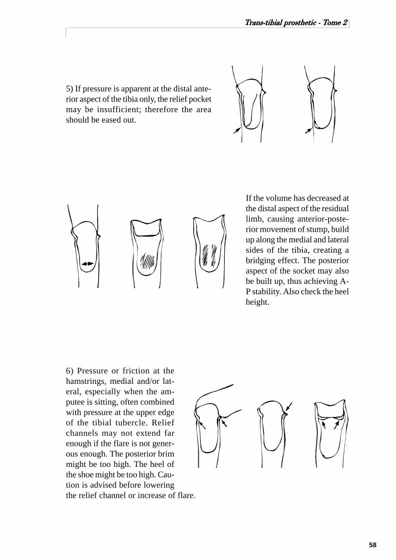
5) If pressure is apparent at the distal ante-rior aspect of the tibia only, the relief pocketmay be insufficient; therefore the areashould be eased out.
If the volume has decreased atthe distal aspect of the residuallimb, causing anterior-poste-rior movement of stump, buildup along the medial and lateralsides of the tibia, creating abridging effect. The posterioraspect of the socket may alsobe built up, thus achieving A-P stability. Also check the heelheight.
6) Pressure or friction at thehamstrings, medial and/or lat-eral, especially when the am-putee is sitting, often combinedwith pressure at the upper edgeof the tibial tubercle. Reliefchannels may not extend farenough if the flare is not gener-ous enough. The posterior brimmight be too high. The heel ofthe shoe might be too high. Cau-tion is advised before loweringthe relief channel or increase of flare.

59
TTTTTrrrrrans-tibial prans-tibial prans-tibial prans-tibial prans-tibial prosthetic - Tosthetic - Tosthetic - Tosthetic - Tosthetic - Tome 2ome 2ome 2ome 2ome 2
7) If the lower edge of the patellacatches at the patellar tendon shelf, onlyperhaps combined with pressure at theupper edge of the tibial tubercle, the pa-tellar tendon shelf may be too wide, of-ten as a result of post-fitting build up.Easing is required as shown.
8) Colour changes. Skin normally changes colour when pressure is applied briefly.However, colour will recover quickly to normal once pressure is removed. Theamputee’s residual limb, however, is subjected, during a normal day of walking andactivities, to continuous pressure within the socket on the skin and muscle tissuethat if is not meant to be subjected to by nature. Therefore, colour changes will andmust take place once the prosthesis is removed. However, it is of utmost impor-tance to note what area the discoloration is restricted to and what time period itrequires to disappear.
Normally after any extended period of walking and quick removal of the prosthesis,the skin will be almost white in the weight-bearing areas quickly turning pinkish tolight red (this should not happen over the bony prominences). The redness shouldrecede slowly to normal colour (5-10 minutes) depending, of course, on skin condi-tion and the vascular state of the individual. If the prosthesis is not removed quicklyenough, the loading areas will have already changed to light redness. One shouldnot be alarmed by this, as stated before, as long as the redness appears in normalloading areas and lot in the pressure sensitive areas, and recedes in the appropriatetime.
If redness is caused by proximal constriction, extreme caution must be taken torecognize and eliminate this problem immediately. This is almost always caused bylack of total contact distally. The soft tissue is not being supported and compressedequally, causing restriction and return flaw of fluid, like forcing a finger in a narrowbottle neck and leaving it there for some time.

60
TTTTTrrrrrans-tibial prans-tibial prans-tibial prans-tibial prans-tibial prosthetic - Tosthetic - Tosthetic - Tosthetic - Tosthetic - Tome 2ome 2ome 2ome 2ome 2
Usually, the discoloration is definitely outlined as if drawn. A circular line willshow exactly where the last socket contact takes place. Of ten the patient will mis-lead the prosthetist by complaining of great pressure distally, encouraging him toenlarge the socket distally and perhaps remove the total contact pad. This will worsenthe problem since more room hasbeen given to be filled by oedema.This ill fitting must be corrected assoon as possible by assuring, first ofall, a proper supporting, non-restrict-ing fit proximally and then filling dis-tal areas of the socket to provide sup-portive counterpressure to the softtissue. Often the constriction is ac-companied by much firmer tissuethat will leave indentation marks.The temperature of the skin is alsohigher.
If constriction has been severe and neglected, it may be necessary to have the am-putee discontinue use of the prosthesis. The patient should then definitely bandagethe residual limb properly and a physician should be called in for consultation.
Most of the time the aforementioned problems are encountered with the dysvascu-lar amputee who has, for whatever reasons, not used his prosthesis without bandag-ing the residual limb, causing the formation of oedema. If the patient then continuesto use the prosthesis and the socket does not accommodate the increased volume ofthe stump. Often the amputee does not recognize this fact and keeps walking, caus-ing further swelling distally since the residual limb does not provide total contact atthis moment.
9) Abrasions are usually the first sign of problems caused by friction. This mayhappen at the distal anterior aspect of the tibia and/or the posterior proximal brim orother protuberances. Abrasions are often caused by poor suspension or loose socketfit. Check and correct. If neglected skin breakdown will become more acute leadingto ulceration or cysts.
10) Haematoma will result when trauma has been induced to the residual limb longenough to leave bruising and blood mass within the tissue. The residual limb isusually hot, firm, red and sensitive. Prosthetic use becomes impossible and restwith stump bandaging should be the treatment. Call in a physician and re-checkprosthetic fit after the haematoma has absolved.
61
TTTTTrrrrrans-tibial prans-tibial prans-tibial prans-tibial prans-tibial prosthetic - Tosthetic - Tosthetic - Tosthetic - Tosthetic - Tome 2ome 2ome 2ome 2ome 2
11) Suspension. The importance of good suspension cannot be overemphasized.The best fitting socket and a perfectly aligned prosthesis will cease to be such if thesuspension is not adequate, of ten leading to a chain reaction of prosthetic prob-lems.
12) Axial Torque, or rotation within the socket, occurs if the residual limb is notsecurely fitted in the socket, or toe in or out is incorrect causing twisting betweenskin and socket interface. Amputees should also be discouraged from turning on theprosthesis during loading if possible. A rotator may be of some benefit.
13) Length of prosthesis. Before making changes, check the socket fit. The residuallimb may have atrophied causing sinking. Oedema build up or poor use of theprosthesis may prevent the residual limb from fitting into the socket, causing length-ening on the amputated side.
14) Shoes. A so called good, sturdy walking shoe should be discouraged for pros-thetic use since it will impair foot function and create undue forces on the residuallimbA light weight, flexible rubber soled shoe that is laced and has a firm heel counterlends itself well for an amputee.
15) Other considerations
Patient education and well planned regular follow-up service is the best way toavoid prosthetic problems or at least keep these problems under control. Follow upin a clinical. Setting with back up from the surgeon-physician, physiotherapist,occupational therapist and nurse.

62
TTTTTrrrrrans-tibial prans-tibial prans-tibial prans-tibial prans-tibial prosthetic - Tosthetic - Tosthetic - Tosthetic - Tosthetic - Tome 2ome 2ome 2ome 2ome 2
SECTION - 8
(ANNEXE)
CUFF SUSPENSION

63
TTTTTrrrrrans-tibial prans-tibial prans-tibial prans-tibial prans-tibial prosthetic - Tosthetic - Tosthetic - Tosthetic - Tosthetic - Tome 2ome 2ome 2ome 2ome 2
CUFF SUSPENSION
The cuff suspension system has two functions:
- It suspend the prosthesis on the stump in swing phase.- It acts slightly against hyperextension of the knee joint during stance phase.
The system consists of:
- a cuff, which is positioned just proximal to the femoral condyles;- the tabs that are attached to the socket and act as suspenders;- the yoke which serves to transmit the tab tension to the cuff.
Cuffs can be prefabricated or made individually. It is always important that theangular relationship between the cuff and tabs remains the same. The buckle islocated on the lateral side.
To determine the attachment points for the tabs on the socket a line is made be-tween the middle of the patella tendon and the posterior wall. The middle of thisline is marked. The tabs should be positioned 1 cm posterior and 1 cm proximal tothis point.
Cuff
Yoke
Tabs

64
TTTTTrrrrrans-tibial prans-tibial prans-tibial prans-tibial prans-tibial prosthetic - Tosthetic - Tosthetic - Tosthetic - Tosthetic - Tome 2ome 2ome 2ome 2ome 2
It is important that an imaginary line between the two attachment points ishorizontal.
To determine the attachmentpoints for the tabs on the socket,a line is made between the mid-dle of the PTB and the posteriorwall. The middle of this line ismarked.
The tabs should be positioned 1cm posterior and 1 cm proximalto this point.
Lateral View
Anteroposteriorcentre of socket
Tab attachmentpoint
1 cm
1 cm
Posterior View Top View
Parallel
Patellar TendonProtuberance
Tab attachmentpointPosterior Wall
Posterior Wall
Parallel
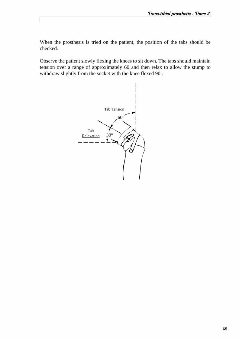
65
TTTTTrrrrrans-tibial prans-tibial prans-tibial prans-tibial prans-tibial prosthetic - Tosthetic - Tosthetic - Tosthetic - Tosthetic - Tome 2ome 2ome 2ome 2ome 2
When the prosthesis is tried on the patient, the position of the tabs should bechecked.
Observe the patient slowly flexing the knees to sit down. The tabs should maintaintension over a range of approximately 60 and then relax to allow the stump towithdraw slightly from the socket with the knee flexed 90 .
Tab Tension
TabRelaxation 30°
60°

66
TTTTTrrrrrans-tibial prans-tibial prans-tibial prans-tibial prans-tibial prosthetic - Tosthetic - Tosthetic - Tosthetic - Tosthetic - Tome 2ome 2ome 2ome 2ome 2
SECTION - 9
(ANNEXE)
LOCATING MECHANICAL
KNEE JOINT
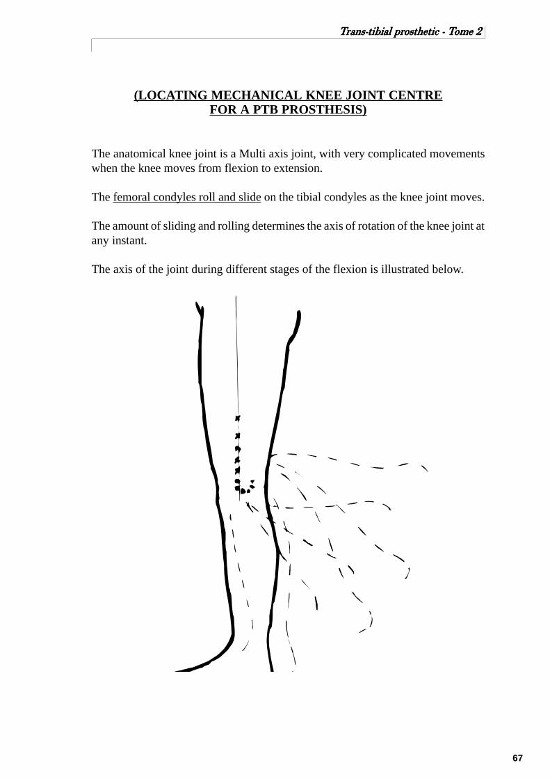
67
TTTTTrrrrrans-tibial prans-tibial prans-tibial prans-tibial prans-tibial prosthetic - Tosthetic - Tosthetic - Tosthetic - Tosthetic - Tome 2ome 2ome 2ome 2ome 2
(LOCATING MECHANICAL KNEE JOINT CENTREFOR A PTB PROSTHESIS)
The anatomical knee joint is a Multi axis joint, with very complicated movementswhen the knee moves from flexion to extension.
The femoral condyles roll and slide on the tibial condyles as the knee joint moves.
The amount of sliding and rolling determines the axis of rotation of the knee joint atany instant.
The axis of the joint during different stages of the flexion is illustrated below.

68
TTTTTrrrrrans-tibial prans-tibial prans-tibial prans-tibial prans-tibial prosthetic - Tosthetic - Tosthetic - Tosthetic - Tosthetic - Tome 2ome 2ome 2ome 2ome 2
Because the anatomical knee joint is Multi axis and the mechanical joint is singleaxis, there will be some relative movement between the amputated leg and theprosthesis when the leg is flexing
The aim is to place the mechanical joints so that they will give the best function andwill minimize the discomfort created by the relative movement.
Effects on relative movement between amputated leg and prosthesiswhen the mechanical joints have different positions.
In order to look at what effect a joint position will have on the relative movement,it will be assumed that the anatomical knee joint acts as a single axis joint.
Also it will be assumed that all the relative movement occurs between the thigh andthe thigh corset, because the stump is held firmly in the socket.
The following figures shows the theoretical situation in which the socket is heldfixed and the stump is not allowed to move in relation to the socket.
With the leg fully extended the upper side bar is parallel to the shaft of femur.
As the knee flexes 90 the mechanical sidebar tends to:
-move anteriorly on the thigh (distance A)
-be drawn distally along the thigh(distance B)
As a result pressure will be created betweenthigh corset and thigh posteriorly; and thestump is forced against the anterior part ofthe brim ( area of patellar tendon)
Mechanical joint aboveanatomical centre
Mechanicaljoint centre
Anatomicaljoint centre
A
B

69
TTTTTrrrrrans-tibial prans-tibial prans-tibial prans-tibial prans-tibial prosthetic - Tosthetic - Tosthetic - Tosthetic - Tosthetic - Tome 2ome 2ome 2ome 2ome 2
As the knee flexes 90 the mechanical side bartends to:
- move posteriorly on the thigh (distance C)
- move proximally on the thigh (distance D)
As a result pressure will be created betweenthigh corset and thigh anteriorly: and thestump is forced posteriorly causing pressurein the popliteal area.
As the knee flexes 90 the mechanical sidebar tend to:
- be forced posteriorly with respect to thethigh ( distance E )
- be forced distally with respect to the thigh( distance F )
As a result pressure is created anteriorlybetween the corset and the thigh; and thestump is forced against the anterior part ofthe socket brim.
Mechanical joint aheadanatomical centre
E
F
Mechanical joint belowanatomical centre
C
D

70
TTTTTrrrrrans-tibial prans-tibial prans-tibial prans-tibial prans-tibial prosthetic - Tosthetic - Tosthetic - Tosthetic - Tosthetic - Tome 2ome 2ome 2ome 2ome 2
As the knee flexes 90 the mechanical sidebar tends to:
-be forced anteriorly with respect to the thigh(distance G )
-move proximally with respect to the thigh(distance H )
As a result pressure is created posteriorlybetween corset and thigh; and the sump isposteriorly causing pressure in poplitealarea.
As the knee flexes 90 the mechanical sidebar will tend to:
-be drawn distally on the thigh (distance I )
- no tendency for the bar to move anteri-orly or posteriorly.
As a result the thigh corset tends to pull thestump anteriorly causing pressure on thepatellar tendon.
Mechanical joint behindanatomical centre
G
H
G
Mechanical joint onanterior 45° diagonal
I
45°

71
TTTTTrrrrrans-tibial prans-tibial prans-tibial prans-tibial prans-tibial prosthetic - Tosthetic - Tosthetic - Tosthetic - Tosthetic - Tome 2ome 2ome 2ome 2ome 2
As the knee flexes 90 the mechanical sidebar will tend to:
-move anteriorly with respect to the stump( distance J )
-no movements distal/proximal.
As a result pressure will be created be-tween the corset and thigh posteriorly.
Best mechanical relationship between Joint axis and Knee axis.
When the side bars are attached to the thigh corset, then movement of the side barswill not happen but movement will happen between the stump and the socket.
There are two situations where relative movement is specially important:
1- when the amputee sits.
2- when the leg is swinging through in swing phase.
1- when the amputee sits.
Joint movement should draw the stump out of the socket, and move it forward sothat there is no pinching of the skin between the socket and thigh corset.
If it is assumed that the amount of upward and forward movement should be thesame, then the joint position should be directly above the anatomical joint centre.
2- when the leg is swinging through in swing phase.
There should be little or no movement between the stump and socket for swingphase control. Therefore the mechanical joint should be close to the anatomicaljoint centre.
Mechanical joint onposterior 45° diagonal
45°
J

72
TTTTTrrrrrans-tibial prans-tibial prans-tibial prans-tibial prans-tibial prosthetic - Tosthetic - Tosthetic - Tosthetic - Tosthetic - Tome 2ome 2ome 2ome 2ome 2
In order to have the best function both when the patient is sitting and during swingphase, the mechanical knee joint should be positioned just slightly above the ana-tomical joint.
All the foregoing analyses are based on consideration that the anatomical knee jointis single axis. Since the anatomical joint is in fact Multi-axis, then ideally mechani-cal joints should be designed to match the anatomical joint. But experience hasshown that the single axis joints can be positioned accurately enough when certainprocedures are used.
The procedure for finding the location of the mechanical knee joint is to mark theMedial Tibial plateau during the casting procedure.
The mechanical joint will be placed 2 cm above the medial tibial plateau, and 1/3anteriorly from the posterior border of the knee.
Medial TibialPlateau
1/3
2/3
Locating mechanical Knee Joint - Medial View
When positioning the mechanical knee joints it is very important that the joints arepositioned:
- Parallel to each other in all planes.
- Parallel to the posterior wall of the socket when looking down into the socket.
- Parallel to the ground and the posterior wall when looking from the back.

73
TTTTTrrrrrans-tibial prans-tibial prans-tibial prans-tibial prans-tibial prosthetic - Tosthetic - Tosthetic - Tosthetic - Tosthetic - Tome 2ome 2ome 2ome 2ome 2
Typical relationship between socket, joints and thigh corset.
Rear View Top View
Side View(Knee Flexed 90°)
2.5 cmClearance
Midpoint
Midpoint
Parallel
Posterior wall Posterior brim
5.5 cm
Patellar TendonProtuberance
Level ofPatellar TendonProtuberance
5.5 cm
74
TTTTTrrrrrans-tibial prans-tibial prans-tibial prans-tibial prans-tibial prosthetic - Tosthetic - Tosthetic - Tosthetic - Tosthetic - Tome 2ome 2ome 2ome 2ome 2
SECTION - 10
(ANNEXE)
THE BK ALIGNMENT COUPLING

75
TTTTTrrrrrans-tibial prans-tibial prans-tibial prans-tibial prans-tibial prosthetic - Tosthetic - Tosthetic - Tosthetic - Tosthetic - Tome 2ome 2ome 2ome 2ome 2
THE BK ALIGNMENT COUPLING
The basic purpose of a BK alignment coupling is to allow the prosthetist to changethe relationship of the socket to the foot during the dynamic alignment procedure.This relationship is in term of height, angulation and location (anteroposterior andmediolateral).
The BK 100 Alignment Coupling
Before the popular use of the modular endoskeletal system, this alignment jig wasthe most commonly used for the initial set up and fitting of the prosthesis.
This particular alignment coupling has essentially three parts:1) the adjustable coupling2) the foot attachment plate3) the pylon tubing.
The B/K 100 alignment coupling offers the prosthetist a maximal amount of adjust-ability in both sagittal and coronal planes. These adjustments include shifting of thesocket medially, laterally, anteriorly or posteriorly and tilting of the socket in thesame four directions.The height of the leg can be adjusted in approximately 1 cm increments by insertingany one of a number of pre-cut pylon tubes.
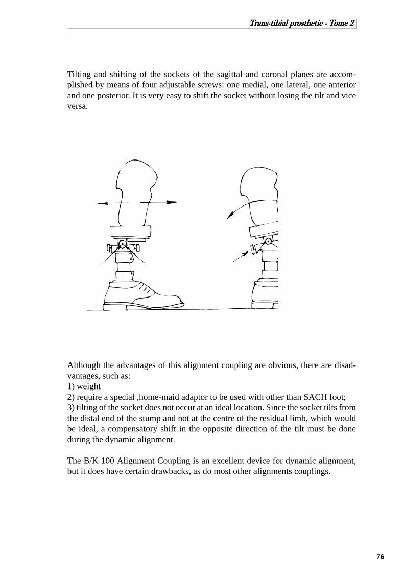
76
TTTTTrrrrrans-tibial prans-tibial prans-tibial prans-tibial prans-tibial prosthetic - Tosthetic - Tosthetic - Tosthetic - Tosthetic - Tome 2ome 2ome 2ome 2ome 2
Tilting and shifting of the sockets of the sagittal and coronal planes are accom-plished by means of four adjustable screws: one medial, one lateral, one anteriorand one posterior. It is very easy to shift the socket without losing the tilt and viceversa.
Although the advantages of this alignment coupling are obvious, there are disad-vantages, such as:1) weight2) require a special ,home-maid adaptor to be used with other than SACH foot;3) tilting of the socket does not occur at an ideal location. Since the socket tilts fromthe distal end of the stump and not at the centre of the residual limb, which wouldbe ideal, a compensatory shift in the opposite direction of the tilt must be doneduring the dynamic alignment.
The B/K 100 Alignment Coupling is an excellent device for dynamic alignment,but it does have certain drawbacks, as do most other alignments couplings.

77
TTTTTrrrrrans-tibial prans-tibial prans-tibial prans-tibial prans-tibial prosthetic - Tosthetic - Tosthetic - Tosthetic - Tosthetic - Tome 2ome 2ome 2ome 2ome 2
Otto Bock Modular System
The Otto Bock modular endoskeletal system for the trans-tibial prosthesis consistsof a foot base plate with connector pylon and, at the opposite end of the pylon, asecond connector with a pyramid plate, connected to a wood block for socket at-tachment.
The alignment changes are achieved at the connector just above the foot and justbelow the socket. If only one coupling is adjusted (this may be at either the socketor foot), a tilt is achieved, mediolaterally or anterior-posteriorly. If both couplingsare adjusted, the distal coupling in the opposite direction from the proximal cou-pling, a shift is achieved. After such an adjustment, the pylon is no longer vertical.
This system may be used for dynamic alignment only, or may be used for perma-nent alignment and given an external cosmetic finish with a shaped foam cover.
When this is complete, and the shoe is on the foot, the pylon should be vertical inboth planes ready for static fitting or alignment.
Tighten screwLoosen screw
Tighten screw
Lateral tilt of socket Anterior tilt of socket
Tilt of socket

78
TTTTTrrrrrans-tibial prans-tibial prans-tibial prans-tibial prans-tibial prosthetic - Tosthetic - Tosthetic - Tosthetic - Tosthetic - Tome 2ome 2ome 2ome 2ome 2
Tighten screwLoosen screwTighten screw
Lateral shift of socket Anterior shift of socket
Loosen screw Loosen screwTighten screw
Shift of socket

79
TTTTTrrrrrans-tibial prans-tibial prans-tibial prans-tibial prans-tibial prosthetic - Tosthetic - Tosthetic - Tosthetic - Tosthetic - Tome 2ome 2ome 2ome 2ome 2
ICRC BK Alignment Components

80
TTTTTrrrrrans-tibial prans-tibial prans-tibial prans-tibial prans-tibial prosthetic - Tosthetic - Tosthetic - Tosthetic - Tosthetic - Tome 2ome 2ome 2ome 2ome 2
REFERENCES
1. Below Knee Prosthetics, Course Work Manual, National School of Prosthetics &Orthotics, Phnom Penh, Cambodia.Carson Harte, Anne Henriksen.
2. Clinical Aspects of Lower Extremity Prosthetics, Trans-tibial, Symes and PartialFoot Amputations, The Canadian Association of Prosthetists and Orthotists.
3. Lower Limb Prosthetics, 1990 Revision, New York University Medical Center.
Compiled and edited by Jacques Forget, CCP (Canadian Certified Prosthetist).

81
TTTTTrrrrrans-tibial prans-tibial prans-tibial prans-tibial prans-tibial prosthetic - Tosthetic - Tosthetic - Tosthetic - Tosthetic - Tome 2ome 2ome 2ome 2ome 2