trahair - flexural-torsional buckling of columns
TRANSCRIPT

Department of Civil Engineering Sydney NSW 2006 AUSTRALIA http://www.civil.usyd.edu.au/ Centre for Advanced Structural Engineering
Flexural-Torsional Buckling of Columns with Oblique Eccentric Restraints Research Report No R841 N S Trahair BSc BE MEngSc PhD DEng and K J R Rasmussen MSciEng PhD November 2004
Department of Civil Engineering Centre for Advanced Structural Engineering
http://www.civil.usyd.edu.au/
Flexural-Torsional Buckling of Columns with Oblique Eccentric Restraints
Research Report No R841
N.S. Trahair, BSc, BE, MEngSc, PhD, DEng K.J.R.Rasmussen, MSciEng, PhD
November 2004 Abstract: This paper is concerned with the elastic flexural-torsional buckling of concentrically loaded columns with oblique eccentric restraints. Oblique flexural restraints may resist deflections as well as flexural rotations, while torsional restraints may resist twist rotations and warping. Flexural restraints may act at the shear centre or may be eccentric. Restraints may be concentrated at points along a column or distributed along portions of its length, and may be rigid or elastic. Oblique flexural restraints cause coupling between the principal axis deflections and rotations, while eccentric flexural restraints cause coupling between the principal axis deflections and rotations and the twist rotations and warping displacements. The general buckling mode involves simultaneous bending about both principal axes and torsion. This paper discusses the nature of oblique eccentric restraints, summarises their finite element analysis, presents examples of their effects on the elastic buckling of columns, and demonstrates the design of columns with oblique eccentric restraints. . Keywords: buckling, columns, design, elasticity, restraints, steel.

Flexural-Torsional Buckling of Columns with Oblique Eccentric Restraints November 2004
Department of Civil Engineering Research Report No R841
2
Copyright Notice Department of Civil Engineering, Research Report R833 Flexural-Torsional Buckling of Columns with Oblique Eccentric Restraints © 2004 N.S.Trahair and K.J.R. Rasmussen [email protected], [email protected] This publication may be redistributed freely in its entirety and in its original form without the consent of the copyright owner. Use of material contained in this publication in any other published works must be appropriately referenced, and, if necessary, permission sought from the author. Published by: Department of Civil Engineering The University of Sydney Sydney NSW 2006 AUSTRALIA November 2004 http://www.civil.usyd.edu.au

Flexural-Torsional Buckling of Columns with Oblique Eccentric Restraints November 2004
Department of Civil Engineering Research Report No R841
3
1 INTRODUCTION This paper is concerned with the elastic flexural-torsional buckling of concentrically loaded columns with oblique eccentric restraints. The restraints may resist deflections as well as rotations, and may be rigid or elastic. They may be concentrated at points along a column, or distributed along portions of its length. This subject may be considered to be the general case of the buckling of a compression member in a three-dimensional frame, which ignores any primary bending moments and inelastic behaviour. The elastic flexural buckling of a doubly symmetric column with restraints which act in a principal plane has been thoroughly researched and is well understood. Such a column buckles in one of the two principal planes xz or yz shown in Fig. 1. In this case, the buckling analysis is simplified to the consideration of the independent planar buckling modes. The effects of unequal rotational end restraints (Trahair et al, 2001) on planar buckling have been analysed, and graphs (SA, 1998 and BSI, 2000) and nomograms (AISC, 1999b) for calculating the column effective length factors used to represent the buckling loads are available. The analysis of the elastic flexural-torsional buckling of simply supported columns of general cross-section is presented in a number of textbooks (Timoshenko and Gere, 1961; Vlasov, 1961; and Trahair, 1993), while the buckling of columns of general cross-section with distributed or concentrated eccentric restraints which act in planes parallel to the principal planes is analysed in Trahair (1993). However, there appear to have been no studies of the elastic flexural-torsional buckling of a column with oblique eccentric restraints which act in an oblique plane Xz inclined at an angle θ to the principal xz plane and eccentric from the column shear centre (S) axis, as shown in Fig. 2. In this case, the oblique restraints cause coupling between the principal axis deflections and rotations, while the restraint eccentricities cause coupling between the deflections and rotations and the twist rotations and warping displacements. The buckling mode involves simultaneous bending about both principal axes and torsion. Practical examples of oblique restraints include angle and zed-section columns connected to restraints through the legs or webs, and columns whose principal axes are rotated relative to restraining beams or grids of beams. Depending on the stiffnesses of the restraining beam(s) relative to the stiffnesses of the column, the supporting beam(s) may be assumed to rigidly or elastically restrain deflections and rotations of the column in one or two oblique planes. Eccentric restraints frequently occur when restraints are connected to the column at points away from the shear centre. Recently, the elastic flexural buckling of doubly symmetric columns with concentrated oblique translational and rotational elastic or rigid restraints has been analysed (Rasmussen and Trahair, 2004; Trahair and Rasmussen, 2005). These analyses have been used to study the effects of restraint type, angle, and stiffness on the flexural buckling of columns with end loads. However, any torsional buckling effects were eliminated from these studies by their restriction to doubly symmetric section columns with concentric restraints.
Flexural-Torsional Buckling of Columns with Oblique Eccentric Restraints November 2004
Department of Civil Engineering Research Report No R841
4
Trahair (1969) studied the elastic buckling of an unequal angle section column with oblique restraint lines (pinned about an XU axis so that the moment MXU = 0 and fixed in the XUz plane so that the rotation dU/dz = 0) at each end. The elastic buckling load varied with the angle θU between the restraint line and the column principal x axis in an approximately sinusoidal fashion. The magnitudes of the buckling loads were affected by torsional effects because of the asymmetry of the unequal angle section. In this paper, only the effects of concentrated oblique eccentric restraints on the elastic flexural-torsional buckling of columns are considered, as the extension to the effects of continuous restraints is very straightforward. The following sections discuss the nature of oblique eccentric restraints, summarise their analysis, present examples of their effects on the elastic buckling of columns, and demonstrate the design of columns with oblique eccentric restraints. 2 ELASTIC RESTRAINTS An elastic column of length L and axial compression N is shown in Fig. 1, in which x and y are the principal axes of the column cross-section and z is the distance along the column. The column is restrained against deflections and rotations at one or more points xU, yU along its length, as shown for example in Fig. 2, in which XU is an oblique restraint axis through the point which is inclined at θU to the x principal axis. The restraints may exert a force FXU which opposes deflection U in the XU direction, a moment MYU which opposes rotation −dU/dz in the XU z plane, and a torque Mz and a bimoment B about the longitudinal axis through the shear centre x0, y0 which oppose a twist rotation φ and warping deflections proportional to dφ /dz. When the column buckles, it deflects u, v parallel to the x, y directions and undergoes twist rotations φ about the longitudinal axis through the shear centre, as shown in Fig. 2. The point xU, yU deflects U in the XU direction and rotates −dU/dz in the XU z plane. These deflections and rotations are related by
)1(}]{[}{ rRR T δδ =in which
)2(}''{}{ TUUR UU φφδ =
is a vector of restraint deformations, ‘ ≡ d/dz,
)3(}'''{}{ Tr vvuu φφδ =
is a vector of principal shear centre deformations, and the transformation matrix [TR] is given by
)4(
100000010000
000000
][ 00
00
⎥⎥⎥⎥
⎦
⎤
⎢⎢⎢⎢
⎣
⎡+−
+−
= UUUUUU
UUUUUU
R
SxCySCSxCySC
T

Flexural-Torsional Buckling of Columns with Oblique Eccentric Restraints November 2004
Department of Civil Engineering Research Report No R841
5
in which
)5(sin)5(cos)5()5(
00
00
dScCbxxxayyy
UU
UU
UU
UU
θθ
==
−=−=
If the restraints are elastic, then they may be expressed as
{ } [ ]{ } )6(RRRF δα=in which
{ } { } )7(TzYUXUR BMMFF =
is the vector of the restraint actions, and
{ } )8(
000000000000
⎥⎥⎥⎥
⎦
⎤
⎢⎢⎢⎢
⎣
⎡
=
w
z
RU
TU
R
αα
αα
α
is the matrix of restraint stiffnesses. When the column buckles, these restraints store strain energy
{ } [ ]{ } )9(21
RRT
RRU δαδ=
which may be transformed into the principal axis system to
{ } [ ]{ } )10(21
rrT
rrU δαδ=
in which [ ] [ ] [ ] [ ] )11(RR
TRr TT αα =

Flexural-Torsional Buckling of Columns with Oblique Eccentric Restraints November 2004
Department of Civil Engineering Research Report No R841
6
3 FINITE ELEMENT ANALYSIS OF ELASTIC BUCKLING A finite element computer program FTBCOR has been prepared which can analyse the elastic buckling of columns with varying axial force and concentrated elastic or rigid oblique eccentric restraints against deflections and rotations which can act at a number of points along the column length. This program uses the principle of conservation of energy at elastic buckling, as expressed by the energy equation δU + δV = 0 (12) in which
( ) { } [ ]{ } )13(21"'""
21
0
2222rr
Tr
re
L
weexeye dzEIGJvEIuEIUe
δαδφφδ ∑∑ ∫ ++++=
[ ] )14(0''2''2'}/){(''2 0
0022
020
22 =+−+++++−= ∑ ∫ dzuyvxyxAIIvuNVe
L
eeeeeyexee
e
φφφλδ
in which E and G are the Young’s and shear moduli of elasticity, Ae is an element’s area, x0e, y0e are the shear centre coordinates, Ixe, Iye are the second moments of area about the x, y principal axes, Le is the length of and Ne is the initial axial force in the element, z is the distance along the element, and λ is the load factor at buckling. In the finite element method, cubic fields (Trahair, 1993) are used to represent the displacements u, v and twist rotations φ in terms of the element nodal deformations {δe}, and the components of Equations 13 and 14 are transformed to
( ) { } [ ]{ } )15(21"'""
21
0
2222 akdzEIGJvEIuEI eeT
e
L
weexeye
e
δδφφ =+++∫
[ ] )15(}]{[}{21''2''2'}/){(''
21
000
220
20
22 bgdzuyvxyxAIIvuNeL
eeT
eeeeeeyexee∫ =+−+++++ δδφφφ
in which [ke] and [ge] are the element stiffness and stability matrices (Trahair, 1993). These are then summed for all the elements to form the global matrices [K] and [G] and these are added to the restraint stiffnesses [αr] to form
{ } [ ] [ ] [ ]( ) { } )16(021
=∆−+∆ GKT λα
Rigid restraints require some of the global deformations {∆} to be condensed out of Equation 16, reducing it to
{ } [ ] [ ] [ ]( ) { } )17(021
=∆−+∆ CCCCT
C GK λα
A discussion of this condensation is given in the following section.
Flexural-Torsional Buckling of Columns with Oblique Eccentric Restraints November 2004
Department of Civil Engineering Research Report No R841
7
The lowest buckling load factor λ and the corresponding buckling mode defined by {∆C} may be extracted from Equation 17 by using standard eigenvalue procedures. The computer program FTBCOR has been written using the MATLAB (Mathworks, 1995) language and functions. 4 RIGID RESTRAINTS The condensations for rigid restraints referred to above are quite straightforward when the rigid restraints prevent one or more of the principal shear centre deformations of Equation 3 since these correspond directly to some of the global deformations {∆}. When the rigid restraints act in oblique planes or are eccentric, it is simpler to transform the corresponding global deformations to the oblique planes, as described below. It is assumed that there are two rigid restraint points, at (xU, yU) as in Fig. 2, and at (xV, yV). Restraint planes XU z and XV z through these two points are inclined at different angles θU, θV to the x axis. Rigid restraints at these two points may prevent translations UU, UV in the XU, XV directions and rotations UU’, UV’ in the XU z, XV z planes. Using Equations 1-4 for both points,
)18(00
00
⎪⎭
⎪⎬
⎫
⎪⎩
⎪⎨
⎧
⎥⎦
⎤⎢⎣
⎡+−+−
=⎭⎬⎫
⎩⎨⎧
φvu
SxCySCSxCySC
UU
VVVVVV
UUUUUU
V
U
whence { } { } )19(][ T
VURRT UUTvu φφ =
in which
)20(
100
)()(
)()(
][ 0000
0000
⎥⎥⎥⎥⎥⎥⎥
⎦
⎤
⎢⎢⎢⎢⎢⎢⎢
⎣
⎡
−−−−
−−−
−−+−−
−−
−
=VUUV
UVVVUUVUVU
VUUV
U
VUUV
V
VUUV
VUVUVUVUVU
VUUV
U
VUUV
V
RR CSCSCSxCSxCCyy
CSCSC
CSCSC
CSCSCSyCSySSxx
CSCSS
CSCSS
T
Similarly,
{ } { } )21('''][''' TVURR
T UUTvu φφ = Equations 19 - 21 may be used to transform the appropriate principal shear centre deformations of the global deformations {∆} into the corresponding oblique eccentric deformations, following which the appropriate oblique eccentric deformations corresponding to the rigid restraints can be condensed out of the transformed Equation 17.

Flexural-Torsional Buckling of Columns with Oblique Eccentric Restraints November 2004
Department of Civil Engineering Research Report No R841
8
5 APPLICATIONS 5.1 Oblique Translational Restraints The finite element computer program has been used to analyse the elastic flexural-torsional buckling of a uniform tee section (Fig. 3a) column whose end deflections and twist rotations are prevented but whose end flexural rotations and warping are free. The properties of the tee section were obtained by using the computer program THIN-WALL (Papangelis and Hancock, 1997) and are shown in Table 1. When the column has no central restraints, then the buckling load N0 is equal to the flexural-torsional buckling load Nyz obtained from (Timoshenko and Gere, 1961 and Trahair, 1993)
)22()/(2
)}/(4){()(20
20
20
20
20
20
2
yrr
yrrNNNNNNN zyzyzy
yz +
+−+−+=
in which
)23(/)(20 AIIr yx +=
)24(/ 22 LEIN yy π=
is the y axis flexural buckling load, and
)25()/()/( 20
20
20
22 yxrLEIGJN wz +++= π is the torsional buckling load. The solutions of Equation 22 for the tee section column (with x0 = 0) are shown in Fig. 4 as the variations of the dimensionless buckling load N0/Nz with the dimensionless length L/Lyz, in which Lyz is the column length at which Ny = Nz. It can be seen that N0 = Nyz decreases from Nz towards Ny as the dimensionless length L/Lyz increases from zero. Also shown in Fig. 4 are the corresponding finite element solutions (obtained using eight equal elements), which are in very close agreement. The finite element predictions for columns with rigid oblique restraints against central translation (at z = L/2) in a plane Xz through the shear centre (S) (and therefore concentric) at θ to the xz principal plane are also shown in Fig. 4. When θ = 90o, the central restraint has no effect on the y axis flexural buckling load, and the column buckles at N0 = Nyz. When θ = 0o, the central restraint increases the y axis flexural buckling load from Ny to a value greater than the x axis flexural buckling load
)26(/ 22 LEIN xx π= and the flexural-torsional buckling load to a value greater than Nyz, so that the column buckles at the lesser of Nx and the increased flexural-torsional buckling load. For intermediate values of θ, the buckling load N0 generally increases from Nyz towards Nx as θ decreases from 90o towards 0o, except at low values of L/Lyz.

Flexural-Torsional Buckling of Columns with Oblique Eccentric Restraints November 2004
Department of Civil Engineering Research Report No R841
9
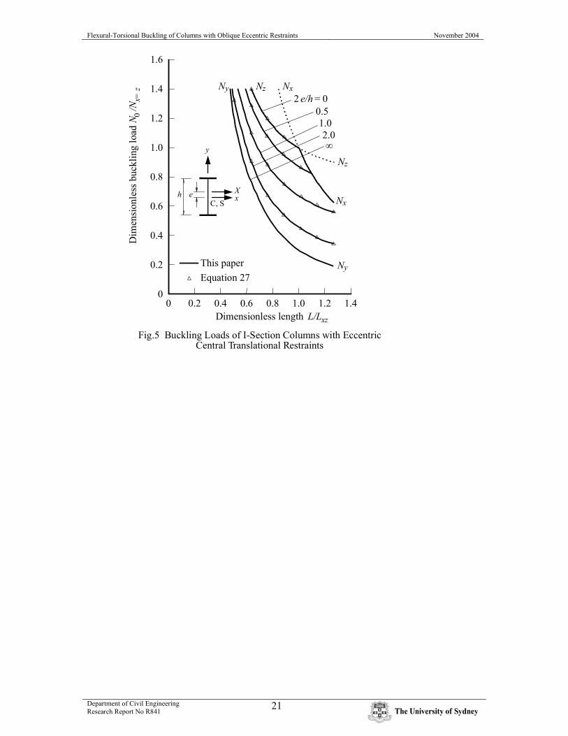
5.2 Eccentric Translational Restraints The finite element computer program has been used to analyse the elastic flexural-torsional buckling of a uniform I-section (Fig. 3b) column whose end deflections and twist rotations are prevented but whose end flexural rotations and warping are free. The properties of the I-section were obtained by using the computer program THIN-WALL (Papangelis and Hancock, 1997) and are shown in Table 1. When the column has no central restraints, then the buckling load N0 is equal to the y axis flexural buckling load Ny, which is lower than the x axis flexural buckling load Nx and the torsional buckling load Nz. The variations of the dimensionless buckling load N0/Nx=z with the dimensionless length L/Lxz (in which Lxz is the column length at which Nx = Nz = Nx=z) are shown in Fig. 5. The finite element predictions for I-section columns with rigid restraints against central translation (at z = L/2) in a plane Xz parallel to the xz plane but at an eccentricity e from the xz principal plane are also shown in Fig. 5. When 2e/h = 0 (in which h is the distance between flange centroids), the central restraint increases the y axis flexural buckling load from Ny to 4Ny > Nx, so that the column buckles at the lower of the torsional buckling load Nz (at low values of L/Lxz) and the x axis flexural buckling load Nx (at high values of L/Lxz). As the dimensionless eccentricity 2e/h increases towards ∞, the buckling load N0 decreases towards Ny. If it is assumed that the central restraint causes the column to buckle with an enforced centre of rotation at an axis through the restraint point (Trahair, 1993), then the buckling load can be determined from
)27(220
20
2
0 errNeN
N zy
+
+=
Solutions obtained from Equation 27 are also shown in Fig. 5. They are very close to the finite element solutions. It is commonly assumed by the designers of steel structures that a rigid central translational restraint is sufficient to increase the elastic buckling load from Ny to the lesser of 4 Ny and Nx. The making of this assumption is encouraged by the absence of a full consideration of the possibility of torsional or flexural-torsional buckling in many design codes (SA, 1998; BSI, 2000; and AISC, 1999a). However, Fig. 5 shows that this assumption is unwarranted, even for concentric restraints, and becomes increasingly dangerous as the eccentricity increases. This danger may be avoided by providing restraints which prevent twist rotation as well as x axis translation.

Flexural-Torsional Buckling of Columns with Oblique Eccentric Restraints November 2004
Department of Civil Engineering Research Report No R841
10
5.3 Oblique Eccentric Restraints 5.3.1 Equal angle section columns The finite element computer program has been used to analyse the elastic flexural-torsional buckling of a uniform equal angle section (Fig. 3c) column whose end deflections and twist rotations are prevented but whose end flexural rotations and warping are free. The properties of the angle section were obtained by using the computer program THIN-WALL (Papangelis and Hancock, 1997) and are shown in Table 1. The buckling load N0 is the lower of (Timoshenko and Gere, 1961 and Trahair, 1993) the y axis flexural buckling load Ny and the flexural-torsional buckling load
)28()/(2
)}/(4){()(20
20
20
20
20
20
2
xrrxrrNNNNNN
N zxzxzxxz +
+−+−+=
The solutions of Equations 24 and 28 for the equal angle section column (with y0 = 0) are shown in Fig. 6 as the variations of the dimensionless buckling load N0/Nz with the dimensionless length L/Lyz. At low values of L/Lyz, Ny > Nxz and the column buckles at N0 = Nxz in a flexural-torsional mode by deflecting v in the y direction and twisting φ. However, at higher values of L/Lyz, Ny < Nxz and the column buckles in a flexural mode at N0 = Ny by deflecting u in the x direction. Also shown in Fig. 6 are the corresponding finite element, which are in very close agreement. The finite element predictions for equal angle section columns with rigid oblique restraints against end rotations in a plane Xz through the centroid (and therefore eccentric to the shear centre) at θ to the xz principal plane are also shown in Fig. 6. When θ = 0o, the end restraints increase the y axis flexural buckling load from Ny to 4Ny = Nx, which is always greater than the flexural-torsional buckling load Nxz, so that the column always buckles at N0 = Nxz. When θ = 90o, the end restraints have no effect on the y axis flexural buckling load, and so the column generally buckles at Ny , except at low values of L/Lyz. For intermediate values of θ, the buckling load generally increases from Ny towards Nxz as θ decreases from 90o towards 0o, except at low values of L/Lyz. 5.3.2 Unequal angle section column The finite element computer program has been used to analyse the elastic flexural-torsional buckling of a uniform unequal angle section (Fig. 3d) column of length 1409.7mm whose end deflections and twist rotations are prevented. The properties of the angle section were obtained by using the computer program THIN-WALL (Papangelis and Hancock, 1997) and are shown in Table 1. The finite element predictions of the variations of the dimensionless buckling load N0/Ny with θ for columns with rigid oblique centroidal restraints against end rotations in a plane Xz at θ to the xz principal plane are shown in Fig. 7. Also shown in Fig. 7 are the corresponding predictions obtained from Trahair (1969). It can be seen that these are generally in close agreement.

Flexural-Torsional Buckling of Columns with Oblique Eccentric Restraints November 2004
Department of Civil Engineering Research Report No R841
11
6 DESIGN OF COLUMNS WITH OBLIQUE RESTRAINTS 6.1 Design by Buckling Analysis The simplest method of designing steel columns with oblique eccentric restraints which is compatible with the widely used methods of designing columns with principal axis concentric restraints is to use the method of design by buckling analysis, which is incorporated either directly or indirectly in design codes such as the AISC Specification (AISC, 1999a), the Australian Standard AS4100 (SA, 1998), or the British Standard BS5950 (BSI, 2000). In this method, the results of an analysis for the elastic buckling load N0 of the obliquely and eccentrically restrained column is used with the squash load
)29(yY AfN = to calculate a modified slenderness
)30()/( 0NNYc =λ which is then used to determine the nominal design capacity Nn . For example, the AISC Specification and the Australian/New Zealand Standard (SA, 1996) for cold-formed steel structures both use
)31()5.1()(/877.0
)31()5.1()(^658.0
2
2
bNN
aNN
ccY
n
ccY
n
>=
≤=
λλ
λλ
as shown in Fig. 8.

Flexural-Torsional Buckling of Columns with Oblique Eccentric Restraints November 2004
Department of Civil Engineering Research Report No R841
12
6.2 Worked Example A 1409.7 mm long steel unequal angle section (UA) column has the dimensions shown in Fig. 3d, the section properties shown in Table 1, and a yield stress of 282.7 MPa (Trahair, 1969). The column is prevented from deflecting and twisting at both ends, and is prevented from rotating in the centroidal plane parallel to the short leg but is free to rotate in the centroidal plane parallel to the long leg at both ends. The design compression capacity may be determined as follows. (Fig. 3d) θ = 180-23.87 = 156.13o
(Fig. 7) N0/Ny = 3.2
(Equation 24) Ny = π2 x 1.9306E5 x 9.052E4 / 1409.72 = 86.8E3 N.
N0 = 3.2 x 86.8E3 = 277.7E3 N.
(Equation 29) NY = 766.1 x 282.7 = 216.5E3 N.
(Equation 30) λc = √(216.5E3 / 277.7E3) = 0.883 < 1.5
(Equation 31a) Nn = 216.5E3 x (0.658 ^ (0.8832)) = 156.2E3 N.
If the capacity factor is 0.85, the design capacity is Nd = 0.85 x 156.2E3 = 132.8E3 N.
7 CONCLUSIONS Column flexural restraints which act in planes oblique to the principal planes cause coupling between the principal axis deflections and rotations, while eccentric (from the shear centre) flexural restraints cause coupling between the principal axis deflections and rotations and the twist rotations and warping displacements. The general buckling mode involves simultaneous bending about both principal axes and torsion. This paper describes a finite element program for analyzing the elastic flexural-torsional buckling of columns under varying axial compression and with oblique, eccentric, concentrated restraints which may be rigid or elastic. The program was validated by comparisons with well-known results for columns with principal axis rotational and translational restraints, and with recently obtained solutions for the flexural buckling of columns with oblique restraints. The program was used to analyse the flexural-torsional buckling of tee section columns with oblique concentric (through the shear centre) central translational restraints. Unrestrained columns buckle in a flexural-torsional mode at loads N0 which tend to the torsional buckling load Nz as the slenderness decreases and to the flexural buckling load Ny as the slenderness increases. Oblique central translational restraints increase the effective flexural buckling loads and so there are consequent increases in the buckling load N0. These increase as the angle θ between the restraint plane and the xz plane decreases from 90o to 0o.

Flexural-Torsional Buckling of Columns with Oblique Eccentric Restraints November 2004
Department of Civil Engineering Research Report No R841
13
The program was also used to analyse the flexural-torsional buckling of I-section columns with eccentric central translational restraints. Unrestrained columns buckle in a flexural mode at loads N0 equal to the flexural buckling load Ny. Eccentric central translational restraints increase the effective flexural buckling load and so there are consequent increases in the buckling load N0. These increase as the eccentricity e decreases towards 0, until the lower of the torsional buckling load Nz and the flexural buckling load Nx is reached. It was concluded that central restraint may not be as effective as is commonly assumed. It is recommended that such restraints be required to prevent twist rotation as well as deflection. The program was also used to analyse the flexural-torsional buckling of equal angle section columns with oblique centroidal (and therefore eccentric from the shear centre) rotational end restraints. Unrestrained columns of low slenderness buckle in a flexural-torsional mode at loads N0 which tend to the torsional buckling load Nz as the slenderness decreases, and to the flexural buckling load Nx as the slenderness increases. At higher slendernesses the buckling load changes to the flexural buckling load Ny. Oblique rotational end restraints increase the effective flexural buckling loads and so there are consequent increases in the buckling load N0. These increase as the angle θ between the restraint plane and the xz plane decreases from 90o to 0o. The program was also used to analyse the flexural-torsional buckling of an unequal angle section column with oblique centroidal (eccentric) rotational end restraints. It was found that the buckling load increases as the angle θ between the restraint plane and the xz plane increases from 90o approximately (when the restraint plane coincides with the stiffer xz principal plane) to 170 o approximately (which is close to the minor yz principal plane), and then decreases. A worked example is presented which demonstrates, by using the method of design by buckling analysis, that restrained steel columns with oblique eccentric restraints can be designed in a way which is consistent with the traditional methods of designing columns with concentric principal axis restraints.

Flexural-Torsional Buckling of Columns with Oblique Eccentric Restraints November 2004
Department of Civil Engineering Research Report No R841
14
APPENDIX 1 REFERENCES
AISC (1999a), Load and Resistance Factor Design Specification for Structural Steel Buildings, American Institute of Steel Construction, Chicago. AISC (1999b), Commentary on the Load and Resistance Factor Design Specification for Structural Steel Buildings, American Institute of Steel Construction, Chicago. BSI (2000), BS 5950 Structural Use of Steelwork in Building. Part 1:2000. Code of Practice for Design in Simple and Continuous Construction: Hot Rolled Sections, British Standards Institution, London. Mathworks Inc (1995), Student Edition of MATLAB, Prentice Hall, Englewood Cliffs, NJ. Papangelis, JP and Hancock, GJ (1997), THIN-WALL – Cross-Section Analysis and Finite Strip Buckling Analysis of Thin-Walled Structures, Centre for Advanced Structural Engineering, University of Sydney. Rasmussen, KJR and Trahair, NS (2004), “Exact and approximate solutions for the flexural buckling of columns with oblique rotational end restraints”, Research Report No. 834, Department of Civil Engineering, University of Sydney. SA (1996), AS/NZS 4600:1996 Cold-Formed Steel Structures, Standards Australia, Sydney. SA (1998), AS 4100-1998 Steel Structures, Standards Australia, Sydney. Timoshenko, SP and Gere, JM (1961), Theory of Elastic Stability, 2nd edition, McGraw-Hill, New York. Trahair, NS (1969), “Restrained elastic beam-columns”, Journal of the Structural Division, ASCE, 95 (ST12), 2641-64. Trahair, NS (1993), Flexural-Torsional Buckling of Structures, E & FN Spon, London. Trahair, NS, Bradford, MA, and Nethercot, DA (2001), The Behaviour and Design of Steel Structures to BS5950, 3rd British edition, E & FN Spon , London. Trahair, NS and Rasmussen, KJR (2005), “Finite element analysis of the flexural buckling of columns with oblique rotational end restraints”, Journal of Structural Engineering, ASCE, 131, in press. Vlasov, VZ (1961), Thin-Walled Elastic Beams, 2nd edn, Israel Program for Scientific Translation, Jerusalem.

Flexural-Torsional Buckling of Columns with Oblique Eccentric Restraints November 2004
Department of Civil Engineering Research Report No R841
15
APPENDIX 2 NOTATION A area of cross-section Ae area of element cross-section B restraint bimoment CU, V cos θU, V e eccentricity of translational restraint E Young’s modulus of elasticity {FR} vector of restraint actions FXU restraint force fy yield stress [G], [K] global stiffness and stability matrices [GC], [KC] condensed global stiffness and stability matrices [ge], [ke] element stiffness and stability matrices h distance between flange centroids Ix, Iy column second moments of area about the x, y principal axes Ixe, Iye element second moments of area about the x, y principal axes L column length Le element length Lxz length of a column for which Nx = Nz Lyz length of a column for which Ny = Nz MXU, MYU restraint moments Mz restraint torque N concentric axial load Nd design compression capacity Ne element axial compression Nn nominal compression capacity Nx, Ny Euler flexural buckling loads Nxz, Nyz flexural- torsional buckling loads Nx=z N0 for a column of length Lxz Nz torsional buckling load NY squash load N0 elastic buckling load r0 radius of gyration SU, V sin θU, V [TR], [TRR] transformation matrices u, v shear centre deflections parallel to the x, y principal axes UR, Ur strain energy of the restraints UU, UV deflections in restraint planes x, y principal axes x0, y0 coordinates of shear centre x0e, y0e element coordinates of shear centre X oblique direction of restraint plane xU, xV x coordinates of restraint points xU0, yV0 x, y distances from restraint point to shear centre yU, yV y coordinates of restraint points z distance along element

Flexural-Torsional Buckling of Columns with Oblique Eccentric Restraints November 2004
Department of Civil Engineering Research Report No R841
16
[α] restraint stiffness matrix [αC] condensed restraint stiffness matrix [αR] oblique restraint stiffness matrix [αr] principal axis restraint stiffness matrix αRU stiffness of rotational restraint αTU stiffness of translational restraint αw stiffness of warping restraint αz stiffness of torsional restraint {δR} vector of oblique plane deformations at a restraint point {δr} vector of principal axis deformations at a restraint point δU increase in strain energy δV increase in potential energy {∆} vector of global nodal deformations {∆C} condensed vector of global nodal deformations θU, θV inclinations of restraint planes to the xz principal plane φ angle of twist rotation λ buckling load factor λc modified slenderness
Quantity T I EA UA A (mm2) 8800 2E4 8000 766.1 Ix (mm4) 3.515E7 6.933E8 5.333E7 5.205E5 Iy (mm4) 2.304E7 2.133E8 1.333E7 9.052E4 J (mm4) 1.173E6 2.267E6 1.067E6 1.030E4 Iw (mm6) 0 8.533E12 0 0 x0 (mm) 0 0 - 70.71 - 17.54 y0 (mm) - 45.46 0 0 - 16.40 E (MPa) 2E5 2E5 2E5 1.9306E5 G (MPa) 8E4 8E4 8E4 7.7224E4
Table 1 Section Properties

Flexural-Torsional Buckling of Columns with Oblique Eccentric Restraints November 2004
Department of Civil Engineering Research Report No R841
17
x
y
N
N
L
Fig.1 Elastic Column

Flexural-Torsional Buckling of Columns with Oblique Eccentric Restraints November 2004
Department of Civil Engineering Research Report No R841
18
u
vS
Mz
y
yU
y0
x0 xU
M YU
FXU
XU U
θUv
u
φ
B
v+(x - x ) φU 0
u-(y - y ) φU 0
x
Fig.2 Restraints
C
,

Flexural-Torsional Buckling of Columns with Oblique Eccentric Restraints November 2004
Department of Civil Engineering Research Report No R841
19
20
200
22020
yx
400
20020
20
10
200
20020
20
73.03
6.35
6.3547.63
y
x23.87°
(a) T-section (T) (b) I-section
(c) Equal angle (EA) (d) Unequal angle (UA)
Fig.3 Section Dimensions (mm)

Flexural-Torsional Buckling of Columns with Oblique Eccentric Restraints November 2004
Department of Civil Engineering Research Report No R841
20
0 0.5 1.0 1.5 2.0 2.5 3.00
0.2
0.4
0.6
0.8
1.0
1.2
1.4
Dim
ensi
onle
ss b
uckl
ing
load
Dimensionless length
Fig.4 Buckling Loads of Tee Section Columns with ObliqueCentral Translational Restraints
0z
yz
NxNy
Nyz
θ= 0°22.5°
45°67.5°90°
This paperEquation 22
θ
X
x
y
C
S
NzN
/N
L/L
Flexural-Torsional Buckling of Columns with Oblique Eccentric Restraints November 2004
Department of Civil Engineering Research Report No R841
21
0 0.2 0.4 0.6 0.8 1.0 1.2 1.40
0.2
0.4
0.6
0.8
1.0
1.2
1.4
1.6
Dim
ensi
onle
ss b
uckl
ing
load
0x=
z
Dimensionless length xz
Fig.5 Buckling Loads of I-Section Columns with EccentricCentral Translational Restraints
Ny Nz Nx
Nz
Nx
NyThis paperEquation 27
20.51.02.0∞
h e Xx
C, S
y
e/h = 0
N /
N
L/L

Flexural-Torsional Buckling of Columns with Oblique Eccentric Restraints November 2004
Department of Civil Engineering Research Report No R841
22
0 1 2 3 40
0.2
0.4
0.6
0.8
1.0
1.2
1.4
Dim
ensi
onle
ss b
uckl
ing
load
Dimensionless length
Fig.6 Buckling Loads of Equal Angle Columns with ObliqueEnd Rotational Restraints
0z
yz
This paperEquations 24, 28
Ny Nx
Nxz
Nxθ= 022.5°45°90° Ny
xθ
Xy
CS
NzN /
N
L/L

Flexural-Torsional Buckling of Columns with Oblique Eccentric Restraints November 2004
Department of Civil Engineering Research Report No R841
23
0 20 40 60 80 100 120 140 160 1800
0.5
1.0
1.5
2.0
2.5
3.0
3.5
Dim
ensi
onle
ss b
uckl
ing
load
0y
Restraint angle
This paperTrahair (1969)
θ°
Fig.7 Buckling Loads of an Unequal Angle with ObliqueEnd Rotational Restraints
xθ
C
yX
S
N /N

Flexural-Torsional Buckling of Columns with Oblique Eccentric Restraints November 2004
Department of Civil Engineering Research Report No R841
24
Fig.8 Design by Buckling Analysis
0 0.5 1.0 1.5 2.0 2.5 3.00
0.2
0.4
0.6
0.8
1.0
1.2
Modified slenderness
Dim
ensi
onle
ss n
omin
al c
apac
ityn
Y
λ = √(N /N )c Y 0
Yielding Y Y
Elastic buckling 0 Y
Nominal capacity n Y(Eq. 31)
N /N
N /N
N /N
N /
N