tracing the evolution of triple offset design - internodepacwa/butterfly/triple offset firesafe...
TRANSCRIPT
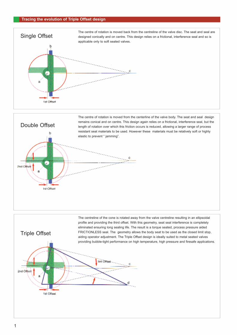
Tracing the evolution of Triple Offset design
The centre of rotation is moved back from the centreline of the valve disc. The seat and seal aredesigned conically and on centre. This design relies on a frictional, interference seal and so isapplicable only to soft seated valves.
The centre of rotation is moved from the centerline of the valve body. The seat and seal designremains conical and on centre. This design again relies on a frictional, interference seal, but thelength of rotation over which this friction occurs is reduced, allowing a larger range of processresistant seat materials to be used. However these materials must be relatively soft or highlyelastic to prevent “ jamming”.
Double Offset
Single Offset
Triple Offset
The centreline of the cone is rotated away from the valve centreline resulting in an ellipsoidalprofile and providing the third offset. With this geometry, seat seal interference is completelyeliminated ensuring long sealing life. The result is a torque seated, process pressure aidedFRICTIONLESS seal. The geometry allows the body seat to be used as the closed limit stop,aiding operator adjustment. The Triple Offset design is ideally suited to metal seated valves providing bubble-tight performance on high temperature, high pressure and firesafe applications.
1
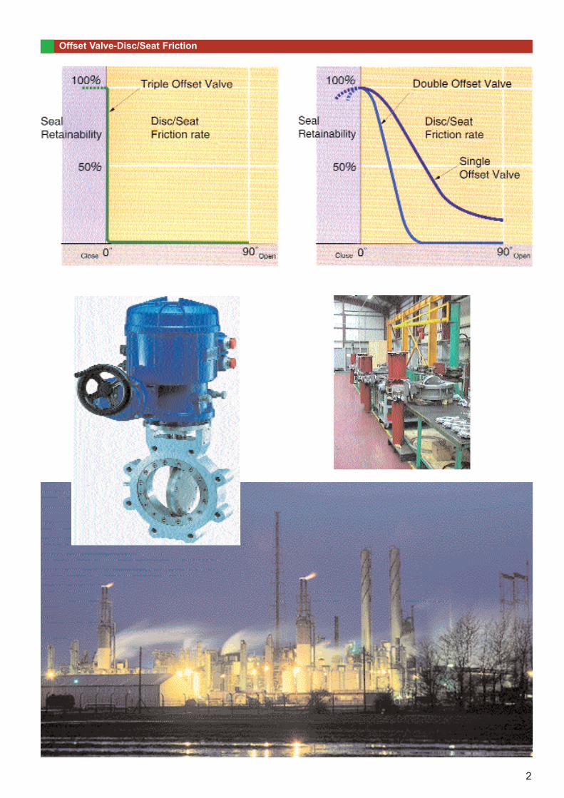
Offset Valve-Disc/Seat Friction
2
Features of the Tritec Valve
Triple offset and ellipsoidal sealing geometryBi-directional zero leakageInherently Firesafe Developed Geometry results in
Zero Seat/Seal FrictionLow Torques Extended Service LifeContinued Seal through Thermal CyclingTorque Seating
Excellent flow and throttling characteristicscovering services from Cryogenic to hightemperature
Excellent control of Fugitive Emission by virtue ofRotary stem movement and advanced packingmaterials
Less than 10ppm on FugitiveEmission Test to cover EPA21
Other tests available on request
Firesafe to BS6755part 2 / API 6FA andAPI Std 607 4th Edition
Available Fully Rated toClass 1500Lb
Fully rated for end ofline duty
Standard materialsconform to NACE,all exotic materials also available.
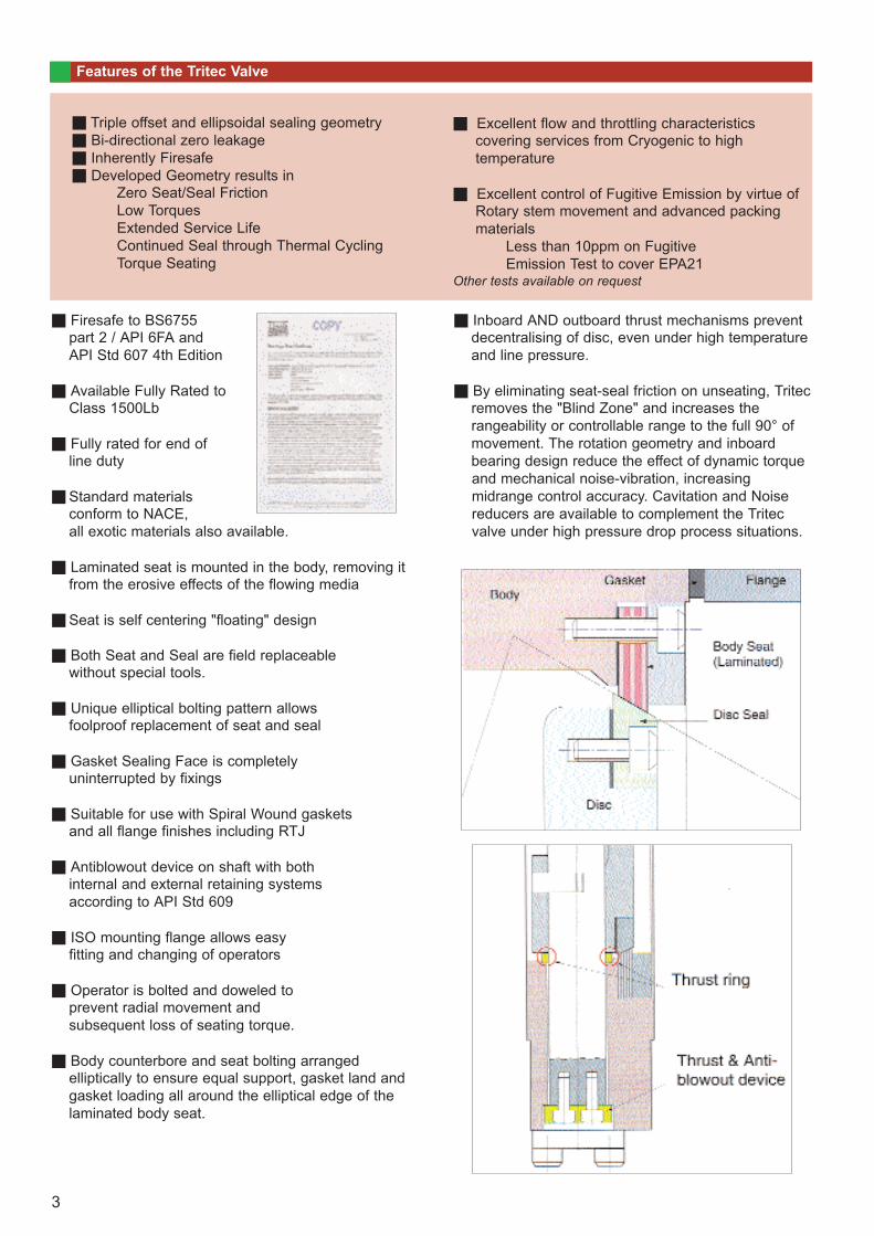
Laminated seat is mounted in the body, removing itfrom the erosive effects of the flowing media
Seat is self centering "floating" design
Both Seat and Seal are field replaceablewithout special tools.
Unique elliptical bolting pattern allowsfoolproof replacement of seat and seal
Gasket Sealing Face is completelyuninterrupted by fixings
Suitable for use with Spiral Wound gasketsand all flange finishes including RTJ
Antiblowout device on shaft with bothinternal and external retaining systemsaccording to API Std 609
ISO mounting flange allows easyfitting and changing of operators
Operator is bolted and doweled toprevent radial movement andsubsequent loss of seating torque.
Body counterbore and seat bolting arrangedelliptically to ensure equal support, gasket land andgasket loading all around the elliptical edge of thelaminated body seat.
Inboard AND outboard thrust mechanisms preventdecentralising of disc, even under high temperatureand line pressure.
By eliminating seat-seal friction on unseating, Tritecremoves the "Blind Zone" and increases therangeability or controllable range to the full 90° ofmovement. The rotation geometry and inboardbearing design reduce the effect of dynamic torqueand mechanical noise-vibration, increasingmidrange control accuracy. Cavitation and Noisereducers are available to complement the Tritecvalve under high pressure drop process situations.
3
Design Options
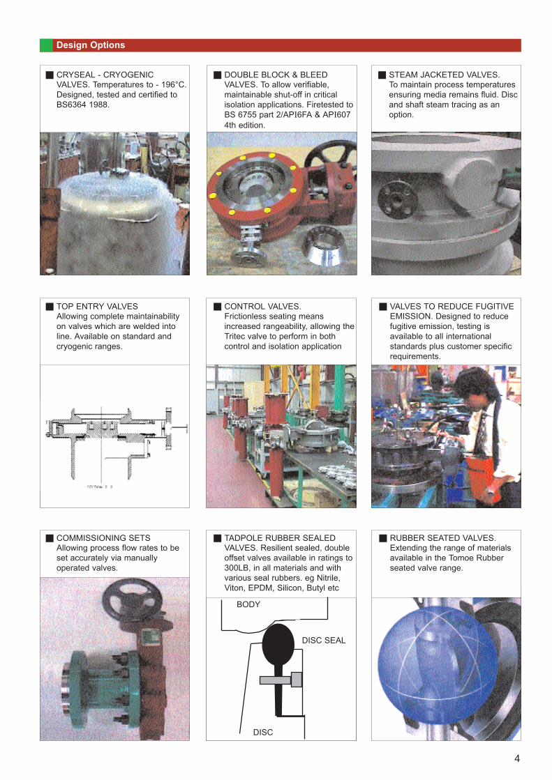
CRYSEAL - CRYOGENIC VALVES. Temperatures to - 196°C.Designed, tested and certified to BS6364 1988.
DOUBLE BLOCK & BLEED VALVES. To allow verifiable, maintainable shut-off in critical isolation applications. Firetested toBS 6755 part 2/API6FA & API607 4th edition.
STEAM JACKETED VALVES. To maintain process temperatures ensuring media remains fluid. Discand shaft steam tracing as an option.
TOP ENTRY VALVESAllowing complete maintainability on valves which are welded into line. Available on standard and cryogenic ranges.
CONTROL VALVES. Frictionless seating means increased rangeability, allowing theTritec valve to perform in both control and isolation application
VALVES TO REDUCE FUGITIVE EMISSION. Designed to reduce fugitive emission, testing is available to all international standards plus customer specific requirements.
COMMISSIONING SETSAllowing process flow rates to be set accurately via manually operated valves.
TADPOLE RUBBER SEALED VALVES. Resilient sealed, double offset valves available in ratings to 300LB, in all materials and with various seal rubbers. eg Nitrile, Viton, EPDM, Silicon, Butyl etc
RUBBER SEATED VALVES. Extending the range of materials available in the Tomoe Rubber seated valve range.
BODY
DISC SEAL
DISC
4
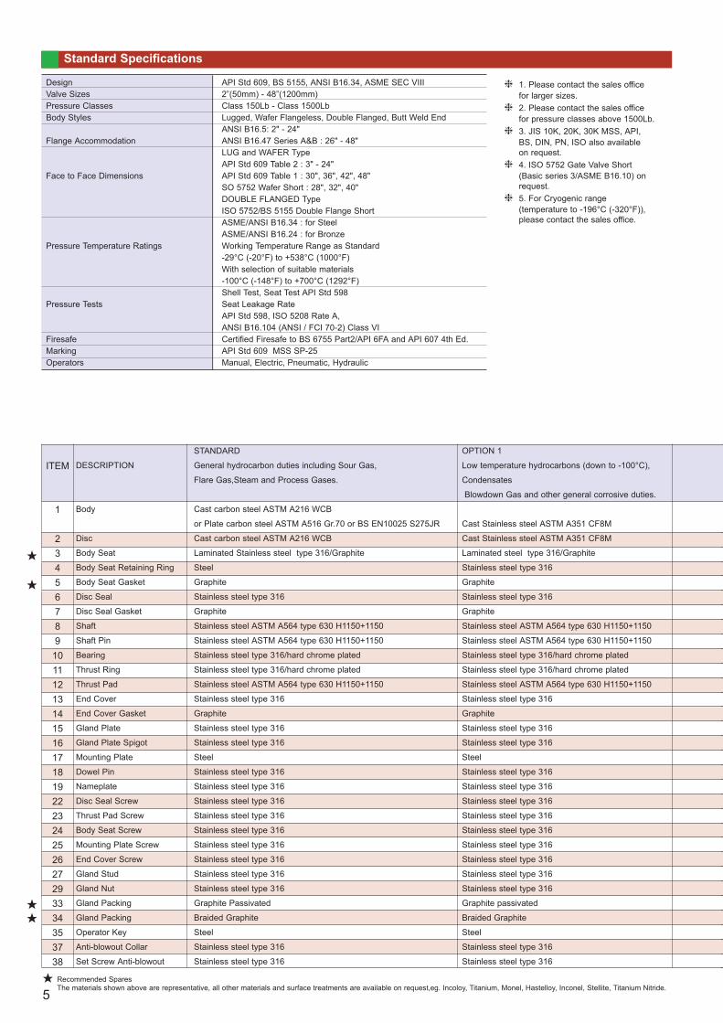
Standard Specifications
DesignValve SizesPressure ClassesBody Styles
Flange Accommodation
Face to Face Dimensions
Pressure Temperature Ratings
Pressure Tests
FiresafeMarkingOperators
API Std 609, BS 5155, ANSI B16.34, ASME SEC VIII2”(50mm) - 48”(1200mm)Class 150Lb - Class 1500LbLugged, Wafer Flangeless, Double Flanged, Butt Weld EndANSI B16.5: 2" - 24"ANSI B16.47 Series A&B : 26" - 48"LUG and WAFER TypeAPI Std 609 Table 2 : 3" - 24"API Std 609 Table 1 : 30", 36", 42", 48"SO 5752 Wafer Short : 28", 32", 40"DOUBLE FLANGED TypeISO 5752/BS 5155 Double Flange ShortASME/ANSI B16.34 : for Steel ASME/ANSI B16.24 : for BronzeWorking Temperature Range as Standard -29°C (-20°F) to +538°C (1000°F) With selection of suitable materials-100°C (-148°F) to +700°C (1292°F)Shell Test, Seat Test API Std 598 Seat Leakage RateAPI Std 598, ISO 5208 Rate A, ANSI B16.104 (ANSI / FCI 70-2) Class VICertified Firesafe to BS 6755 Part2/API 6FA and API 607 4th Ed.API Std 609 MSS SP-25Manual, Electric, Pneumatic, Hydraulic
1. Please contact the sales office for larger sizes. 2. Please contact the sales office for pressure classes above 1500Lb. 3. JIS 10K, 20K, 30K MSS, API, BS, DIN, PN, ISO also available on request.4. ISO 5752 Gate Valve Short (Basic series 3/ASME B16.10) on request.5. For Cryogenic range (temperature to -196°C (-320°F)), please contact the sales office.
ITEM
1
2345678910111213141516171819222324252627293334353738
DESCRIPTION
Body
Disc
Body Seat
Body Seat Retaining Ring
Body Seat Gasket
Disc Seal
Disc Seal Gasket
Shaft
Shaft Pin
Bearing
Thrust Ring
Thrust Pad
End Cover
End Cover Gasket
Gland Plate
Gland Plate Spigot
Mounting Plate
Dowel Pin
Nameplate
Disc Seal Screw
Thrust Pad Screw
Body Seat Screw
Mounting Plate Screw
End Cover Screw
Gland Stud
Gland Nut
Gland Packing
Gland Packing
Operator Key
Anti-blowout Collar
Set Screw Anti-blowout
STANDARD
General hydrocarbon duties including Sour Gas,
Flare Gas,Steam and Process Gases.
Cast carbon steel ASTM A216 WCB
or Plate carbon steel ASTM A516 Gr.70 or BS EN10025 S275JR
Cast carbon steel ASTM A216 WCB
Laminated Stainless steel type 316/Graphite
Steel
Graphite
Stainless steel type 316
Graphite
Stainless steel ASTM A564 type 630 H1150+1150
Stainless steel ASTM A564 type 630 H1150+1150
Stainless steel type 316/hard chrome plated
Stainless steel type 316/hard chrome plated
Stainless steel ASTM A564 type 630 H1150+1150
Stainless steel type 316
Graphite
Stainless steel type 316
Stainless steel type 316
Steel
Stainless steel type 316
Stainless steel type 316
Stainless steel type 316
Stainless steel type 316
Stainless steel type 316
Stainless steel type 316
Stainless steel type 316
Stainless steel type 316
Stainless steel type 316
Graphite Passivated
Braided Graphite
Steel
Stainless steel type 316
Stainless steel type 316
OPTION 1
Low temperature hydrocarbons (down to -100°C),
Condensates
Blowdown Gas and other general corrosive duties.
Cast Stainless steel ASTM A351 CF8M
Cast Stainless steel ASTM A351 CF8M
Laminated steel type 316/Graphite
Stainless steel type 316
Graphite
Stainless steel type 316
Graphite
Stainless steel ASTM A564 type 630 H1150+1150
Stainless steel ASTM A564 type 630 H1150+1150
Stainless steel type 316/hard chrome plated
Stainless steel type 316/hard chrome plated
Stainless steel ASTM A564 type 630 H1150+1150
Stainless steel type 316
Graphite
Stainless steel type 316
Stainless steel type 316
Steel
Stainless steel type 316
Stainless steel type 316
Stainless steel type 316
Stainless steel type 316
Stainless steel type 316
Stainless steel type 316
Stainless steel type 316
Stainless steel type 316
Stainless steel type 316
Graphite passivated
Braided Graphite
Steel
Stainless steel type 316
Stainless steel type 316
Recommended SparesThe materials shown above are representative, all other materials and surface treatments are available on request,eg. Incoloy, Titanium, Monel, Hastelloy, Inconel, Stellite, Titanium Nitride. 5
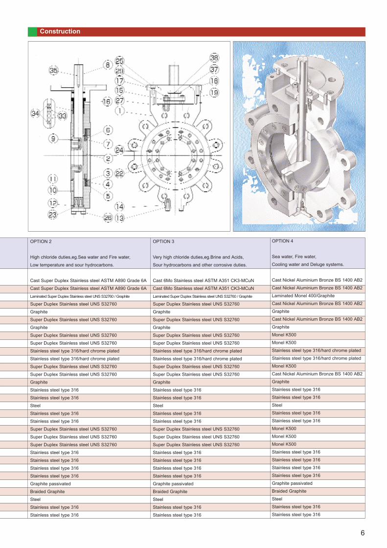
OPTION 2
High chloride duties,eg.Sea water and Fire water,
Low temperature and sour hydrocarbons.
Cast Super Duplex Stainless steel ASTM A890 Grade 6A
Cast Super Duplex Stainless steel ASTM A890 Grade 6A
Laminated Super Duplex Stainless steel UNS S32760 / Graphite
Super Duplex Stainless steel UNS S32760
Graphite
Super Duplex Stainless steel UNS S32760
Graphite
Super Duplex Stainless steel UNS S32760
Super Duplex Stainless steel UNS S32760
Stainless steel type 316/hard chrome plated
Stainless steel type 316/hard chrome plated
Super Duplex Stainless steel UNS S32760
Super Duplex Stainless steel UNS S32760
Graphite
Stainless steel type 316
Stainless steel type 316
Steel
Stainless steel type 316
Stainless steel type 316
Super Duplex Stainless steel UNS S32760
Super Duplex Stainless steel UNS S32760
Super Duplex Stainless steel UNS S32760
Stainless steel type 316
Stainless steel type 316
Stainless steel type 316
Stainless steel type 316
Graphite passivated
Braided Graphite
Steel
Stainless steel type 316
Stainless steel type 316
OPTION 3
Very high chloride duties,eg.Brine and Acids,
Sour hydrocarbons and other corrosive duties.
Cast 6Mo Stainless steel ASTM A351 CK3-MCuN
Cast 6Mo Stainless steel ASTM A351 CK3-MCuN
Laminated Super Duplex Stainless steel UNS S32760 / Graphite
Super Duplex Stainless steel UNS S32760
Graphite
Super Duplex Stainless steel UNS S32760
Graphite
Super Duplex Stainless steel UNS S32760
Super Duplex Stainless steel UNS S32760
Stainless steel type 316/hard chrome plated
Stainless steel type 316/hard chrome plated
Super Duplex Stainless steel UNS S32760
Super Duplex Stainless steel UNS S32760
Graphite
Stainless steel type 316
Stainless steel type 316
Steel
Stainless steel type 316
Stainless steel type 316
Super Duplex Stainless steel UNS S32760
Super Duplex Stainless steel UNS S32760
Super Duplex Stainless steel UNS S32760
Stainless steel type 316
Stainless steel type 316
Stainless steel type 316
Stainless steel type 316
Graphite passivated
Braided Graphite
Steel
Stainless steel type 316
Stainless steel type 316
OPTION 4
Sea water, Fire water,
Cooling water and Deluge systems.
Cast Nickel Aluminium Bronze BS 1400 AB2
Cast Nickel Aluminium Bronze BS 1400 AB2
Laminated Monel 400/Graphite
Cast Nickel Aluminium Bronze BS 1400 AB2
Graphite
Cast Nickel Aluminium Bronze BS 1400 AB2
Graphite
Monel K500
Monel K500
Stainless steel type 316/hard chrome plated
Stainless steel type 316/hard chrome plated
Monel K500
Cast Nickel Aluminium Bronze BS 1400 AB2
Graphite
Stainless steel type 316
Stainless steel type 316
Steel
Stainless steel type 316
Stainless steel type 316
Monel K500
Monel K500
Monel K500
Stainless steel type 316
Stainless steel type 316
Stainless steel type 316
Stainless steel type 316
Graphite passivated
Braided Graphite
Steel
Stainless steel type 316
Stainless steel type 316
Construction
6
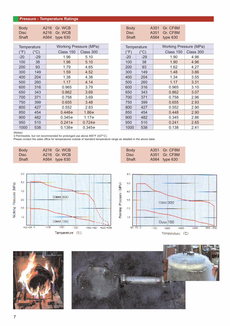
Pressure - Temperature Ratings
BodyDiscShaft
A216 Gr. WCBA216 Gr. WCBA564 type 630
BodyDiscShaft
A351 Gr. CF8MA351 Gr. CF8MA564 type 630
BodyDiscShaft
A216 Gr. WCBA216 Gr. WCBA564 type 630
BodyDiscShaft
A351 Gr. CF8MA351 Gr. CF8MA564 type 630
Temperature(°F) (°C)-201002003004005006006507007508008509009501000
-293893149204260316343371399427454482510538
Class 1501.96 1.96 1.79 1.59 1.38 1.17 0.9650.8620.7580.6550.552
0.4480.3450.2410.138
Working Pressure (MPa) Working Pressure (MPa)Class 300
5.10 5.10 4.65 4.52 4.38 4.14 3.79 3.69 3.69 3.48 2.83
1.861.170.7240.345
Class 1501.90 1.90 1.62 1.48 1.34 1.17 0.9650.8620.7580.6550.5520.4480.3450.2410.138
Class 3004.964.964.273.863.553.313.103.072.962.932.902.902.862.652.41
Temperature(°F) (°C)-201002003004005006006507007508008509009501000
-293893149204260316343371399427454482510538
(Notes) Permissible, but not recommended for prolonged use above 800°F (427°C).
Please contact the sales office for temperatures outside of standard temperature range as detailed in the above table.
7
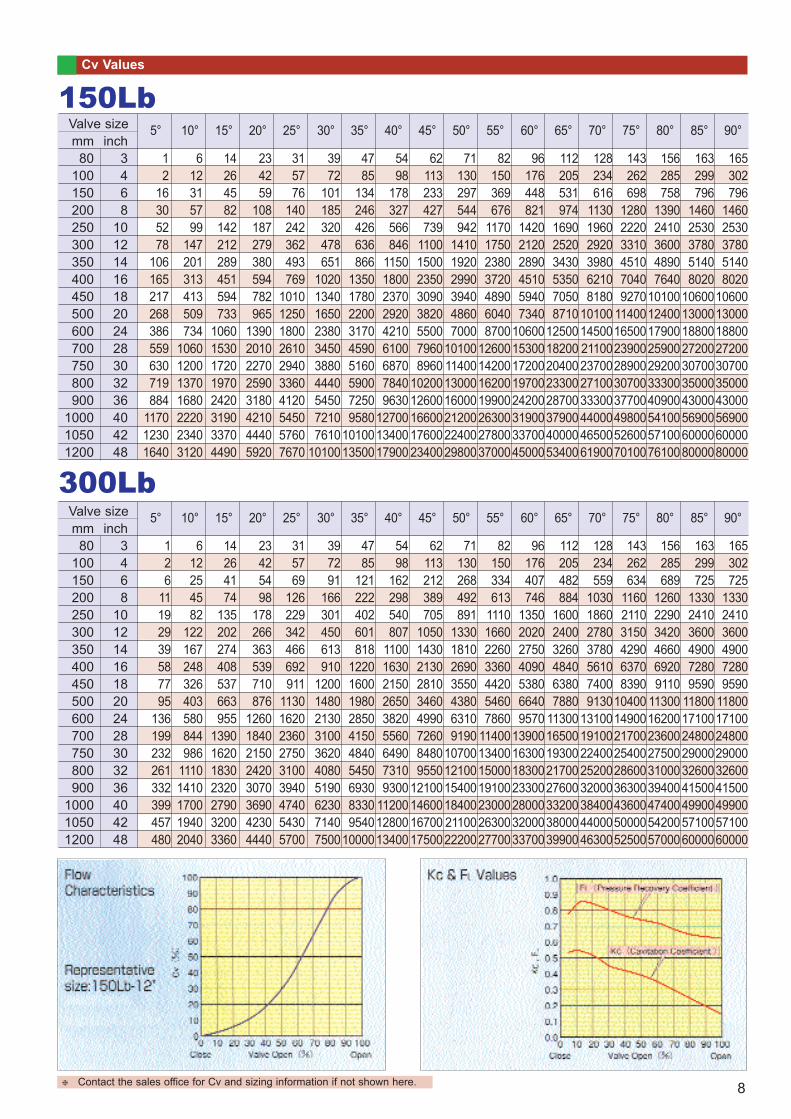
Cv Values
mm80
100150200250300350400450500600700750800900
100010501200
inch3468
1012141618202428303236404248
12
16305278
106165217268386559630719884
117012301640
5°
612315799
147201313413509734
1060120013701680222023403120
14264582
142212289451594733
10601530172019702420319033704490
234259
108187279380594782965
13902010227025903180421044405920
315776
140242362493769
1010125018002610294033604120545057607670
3972
101185320478651
1020134016502380345038804440545072107610
10100
4785
134246426636866
135017802200317045905160590072509580
1010013500
5498
178327566846
115018002370292042106100687078409630
127001340017900
62113233427739
11001500235030903820550079608960
1020012600166001760023400
71130297544942
141019202990394048607000
10100114001300016000212002240029800
82150369676
1170175023803720489060408700
12600142001620019900263002780037000
96176448821
142021202890451059407340
1060015300172001970024200319003370045000
112205531974
169025203430535070508710
1250018200204002330028700379004000053400
128234616
113019602920398062108180
101001450021100237002710033300440004650061900
143262698
128022203310451070409270
114001650023900289003070037700498005260070100
156285758
13902410360048907640
10100124001790025900292003330040900541005710076100
163299796
14602530378051408020
10600130001880027200307003500043000569006000080000
165302796
14602530378051408020
10600130001880027200307003500043000569006000080000
Valve size150Lb
10° 15° 20° 25° 30° 35° 40° 45° 50° 55° 60° 65° 70° 75° 80° 85° 90°
mm80
100150200250300350400450500600700750800900
100010501200
inch3468
1012141618202428303236404248
126
11192939587795
136199232261332399457480
5°
612254582
122167248326403580844986
11101410170019402040
14264174
135202274408537663955
1390162018302320279032003360
23425498
178266363539710876
12601840215024203070369042304440
315769
126229342466692911
113016202360275031003940474054305700
397291
166301450613910
1200148021303100362040805190623071407500
4785
121222402601818
1220160019802850415048405450693083309540
10000
5498
162298540807
110016302150265038205560649073109300
112001280013400
62113212389705
105014302130281034604990726084809550
12100146001670017500
71130268492891
1330181026903550438063109190
107001210015400184002110022200
82150334613
1110166022603360442054607860
11400134001500019100230002630027700
96176407746
1350202027504090538066409570
13900163001830023300280003200033700
112205482884
160024003260484063807880
1130016500193002170027600332003800039900
128234559
1030186027803780561074009130
1310019100224002520032000384004400046300
143262634
116021103150429063708390
104001490021700254002860036300436005000052500
156285689
126022903420466069209110
113001620023600275003100039400474005420057000
163299725
133024103600490072809590
118001710024800290003260041500499005710060000
165302725
133024103600490072809590
118001710024800290003260041500499005710060000
Valve size
300Lb10° 15° 20° 25° 30° 35° 40° 45° 50° 55° 60° 65° 70° 75° 80° 85° 90°
Contact the sales office for Cv and sizing information if not shown here. 8
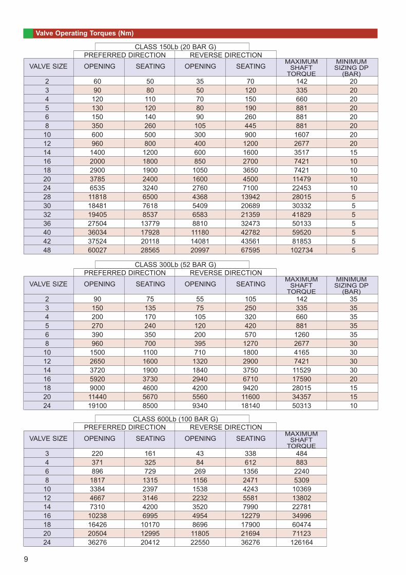
Valve Operating Torques (Nm)
2 60 50 35 70 142 203 90 80 50 120 335 204 120 110 70 150 660 205 130 120 80 190 881 206 150 140 90 260 881 208 350 260 105 445 881 2010 600 500 300 900 1607 2012 960 800 400 1200 2677 2014 1400 1200 600 1600 3517 1516 2000 1800 850 2700 7421 1018 2900 1900 1050 3650 7421 1020 3785 2400 1600 4500 11479 1024 6535 3240 2760 7100 22453 1028 11818 6500 4368 13942 28015 530 18481 7618 5409 20689 30332 532 19405 8537 6583 21359 41829 536 27504 13779 8810 32473 50133 540 36034 17928 11180 42782 59520 542 37524 20118 14081 43561 81853 548 60027 28565 20997 67595 102734 5
VALVE SIZE OPENINGPREFERRED DIRECTION REVERSE DIRECTION
CLASS 150Lb (20 BAR G)
SEATING OPENING SEATINGMAXIMUM
SHAFTTORQUE
MINIMUM SIZING DP
(BAR)
2 90 75 55 105 142 353 150 135 75 250 335 354 200 170 105 320 660 355 270 240 120 420 881 356 390 350 200 570 1260 358 960 700 395 1270 2677 3010 1500 1100 710 1800 4165 3012 2650 1600 1320 2900 7421 3014 3720 1900 1840 3750 11529 3016 5920 3730 2940 6710 17590 2018 9000 4600 4200 9420 28015 1520 11440 5670 5560 11600 34357 1524 19100 8500 9340 18140 50313 10
VALVE SIZE OPENINGPREFERRED DIRECTION REVERSE DIRECTION
CLASS 300Lb (52 BAR G)
SEATING OPENING SEATINGMAXIMUM
SHAFTTORQUE
MINIMUM SIZING DP
(BAR)
3 220 161 43 338 4844 371 325 84 612 8836 896 729 269 1356 22408 1817 1315 1156 2471 530910 3384 2397 1538 4243 1036912 4667 3146 2232 5581 1380214 7310 4200 3520 7990 2278116 10238 6995 4954 12279 3499618 16426 10170 8696 17900 6047420 20504 12995 11805 21694 7112324 36276 20412 22550 36276 126164
VALVE SIZE OPENINGPREFERRED DIRECTION REVERSE DIRECTION
CLASS 600Lb (100 BAR G)
SEATING OPENING SEATINGMAXIMUM
SHAFTTORQUE
9
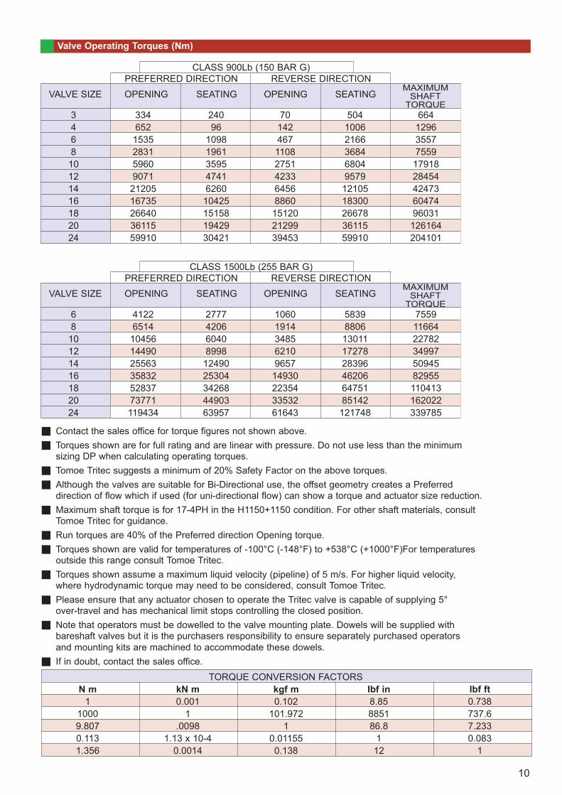
Valve Operating Torques (Nm)
3 334 240 70 504 6644 652 96 142 1006 12966 1535 1098 467 2166 35578 2831 1961 1108 3684 755910 5960 3595 2751 6804 1791812 9071 4741 4233 9579 2845414 21205 6260 6456 12105 4247316 16735 10425 8860 18300 6047418 26640 15158 15120 26678 9603120 36115 19429 21299 36115 12616424 59910 30421 39453 59910 204101
VALVE SIZE OPENINGPREFERRED DIRECTION REVERSE DIRECTION
CLASS 900Lb (150 BAR G)
SEATING OPENING SEATINGMAXIMUM
SHAFTTORQUE
6 4122 2777 1060 5839 75598 6514 4206 1914 8806 1166410 10456 6040 3485 13011 2278212 14490 8998 6210 17278 3499714 25563 12490 9657 28396 5094516 35832 25304 14930 46206 8295518 52837 34268 22354 64751 11041320 73771 44903 33532 85142 16202224 119434 63957 61643 121748 339785
VALVE SIZE OPENINGPREFERRED DIRECTION REVERSE DIRECTION
CLASS 1500Lb (255 BAR G)
SEATING OPENING SEATINGMAXIMUM
SHAFTTORQUE
Contact the sales office for torque figures not shown above.Torques shown are for full rating and are linear with pressure. Do not use less than the minimum sizing DP when calculating operating torques. Tomoe Tritec suggests a minimum of 20% Safety Factor on the above torques.Although the valves are suitable for Bi-Directional use, the offset geometry creates a Preferred direction of flow which if used (for uni-directional flow) can show a torque and actuator size reduction. Maximum shaft torque is for 17-4PH in the H1150+1150 condition. For other shaft materials, consult Tomoe Tritec for guidance.Run torques are 40% of the Preferred direction Opening torque.Torques shown are valid for temperatures of -100°C (-148°F) to +538°C (+1000°F)For temperatures outside this range consult Tomoe Tritec.Torques shown assume a maximum liquid velocity (pipeline) of 5 m/s. For higher liquid velocity, where hydrodynamic torque may need to be considered, consult Tomoe Tritec. Please ensure that any actuator chosen to operate the Tritec valve is capable of supplying 5° over-travel and has mechanical limit stops controlling the closed position.Note that operators must be dowelled to the valve mounting plate. Dowels will be supplied with bareshaft valves but it is the purchasers responsibility to ensure separately purchased operators and mounting kits are machined to accommodate these dowels. If in doubt, contact the sales office.
N m kN m kgf m Ibf in Ibf ft1 0.001 0.102 8.85 0.738
1000 1 101.972 8851 737.69.807 .0098 1 86.8 7.2330.113 1.13 x 10⁻⁴ 0.01155 1 0.0831.356 0.0014 0.138 12 1
TORQUE CONVERSION FACTORS
10
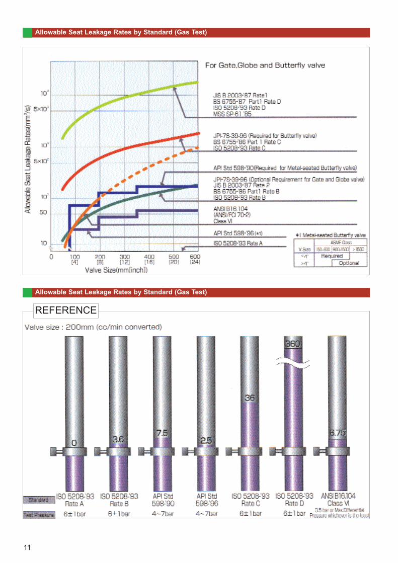
Allowable Seat Leakage Rates by Standard (Gas Test)
Allowable Seat Leakage Rates by Standard (Gas Test)
REFERENCE
11
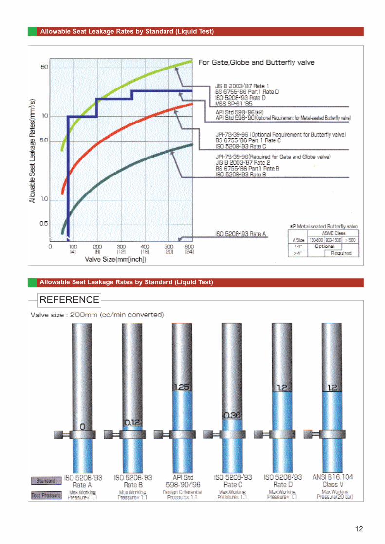
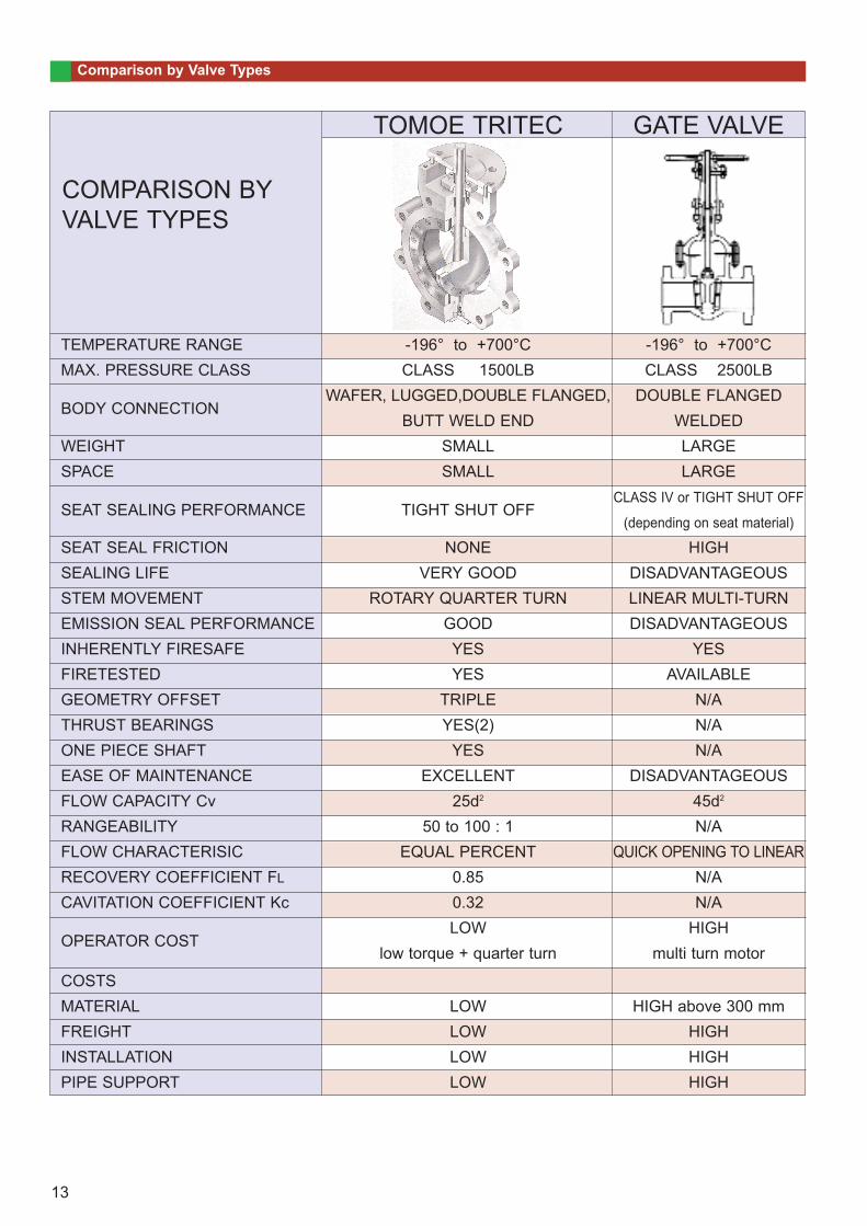
Allowable Seat Leakage Rates by Standard (Liquid Test)
Allowable Seat Leakage Rates by Standard (Liquid Test)
REFERENCE
12
Comparison by Valve Types
TEMPERATURE RANGEMAX. PRESSURE CLASS
BODY CONNECTION
WEIGHTSPACE
SEAT SEALING PERFORMANCE
SEAT SEAL FRICTIONSEALING LIFESTEM MOVEMENTEMISSION SEAL PERFORMANCEINHERENTLY FIRESAFEFIRETESTEDGEOMETRY OFFSETTHRUST BEARINGSONE PIECE SHAFTEASE OF MAINTENANCEFLOW CAPACITY Cv RANGEABILITYFLOW CHARACTERISICRECOVERY COEFFICIENT FL
CAVITATION COEFFICIENT Kc
OPERATOR COST
COSTSMATERIALFREIGHTINSTALLATIONPIPE SUPPORT
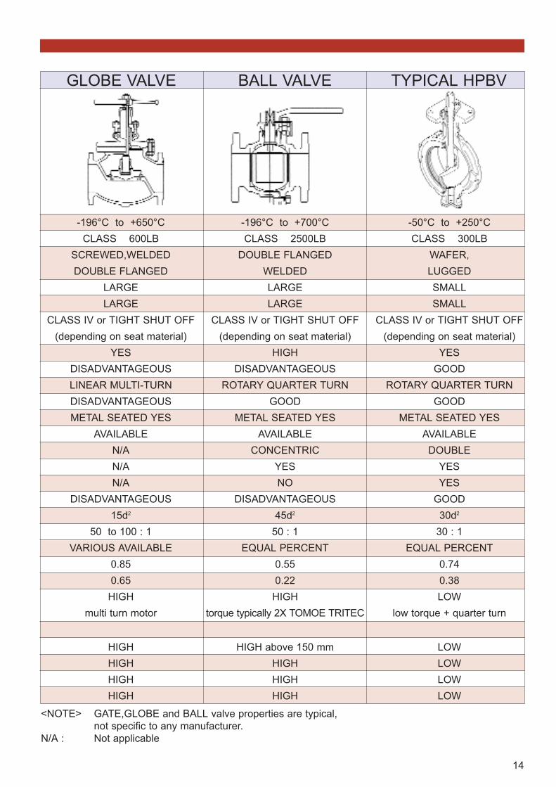
-196° to +700°C CLASS 1500LB
WAFER, LUGGED,DOUBLE FLANGED,BUTT WELD END
SMALLSMALL
TIGHT SHUT OFF
NONEVERY GOOD
ROTARY QUARTER TURNGOODYESYES
TRIPLEYES(2)
YESEXCELLENT
25d2
50 to 100 : 1EQUAL PERCENT
0.850.32LOW
low torque + quarter turn
LOWLOWLOWLOW
-196° to +700°C CLASS 2500LB
DOUBLE FLANGEDWELDEDLARGELARGE
CLASS IV or TIGHT SHUT OFF
(depending on seat material)
HIGHDISADVANTAGEOUSLINEAR MULTI-TURNDISADVANTAGEOUS
YESAVAILABLE
N/AN/AN/A
DISADVANTAGEOUS45d2
N/AQUICK OPENING TO LINEAR
N/AN/A
HIGHmulti turn motor
HIGH above 300 mmHIGHHIGHHIGH
COMPARISON BYVALVE TYPES
TOMOE TRITEC GATE VALVE
13
-196°C to +650°CCLASS 600LB
SCREWED,WELDEDDOUBLE FLANGED
LARGELARGE
CLASS IV or TIGHT SHUT OFF(depending on seat material)
YESDISADVANTAGEOUSLINEAR MULTI-TURNDISADVANTAGEOUSMETAL SEATED YES
AVAILABLEN/AN/AN/A
DISADVANTAGEOUS15d2
50 to 100 : 1VARIOUS AVAILABLE
0.850.65HIGH
multi turn motor
HIGHHIGHHIGHHIGH
-196°C to +700°CCLASS 2500LB
DOUBLE FLANGEDWELDEDLARGELARGE
CLASS IV or TIGHT SHUT OFF(depending on seat material)
HIGHDISADVANTAGEOUS
ROTARY QUARTER TURNGOOD
METAL SEATED YESAVAILABLE
CONCENTRICYESNO
DISADVANTAGEOUS45d2
50 : 1EQUAL PERCENT
0.550.22HIGH
torque typically 2X TOMOE TRITEC
HIGH above 150 mmHIGHHIGHHIGH
-50°C to +250°CCLASS 300LB
WAFER,LUGGEDSMALLSMALL
CLASS IV or TIGHT SHUT OFF(depending on seat material)
YESGOOD
ROTARY QUARTER TURNGOOD
METAL SEATED YESAVAILABLE
DOUBLEYESYES
GOOD30d2
30 : 1EQUAL PERCENT
0.740.38LOW
low torque + quarter turn
LOWLOWLOWLOW
<NOTE> GATE,GLOBE and BALL valve properties are typical, not specific to any manufacturer.
N/A : Not applicable
GLOBE VALVE TYPICAL HPBVBALL VALVE
14
150LbAllowable Min.Internal Diameter for Piping
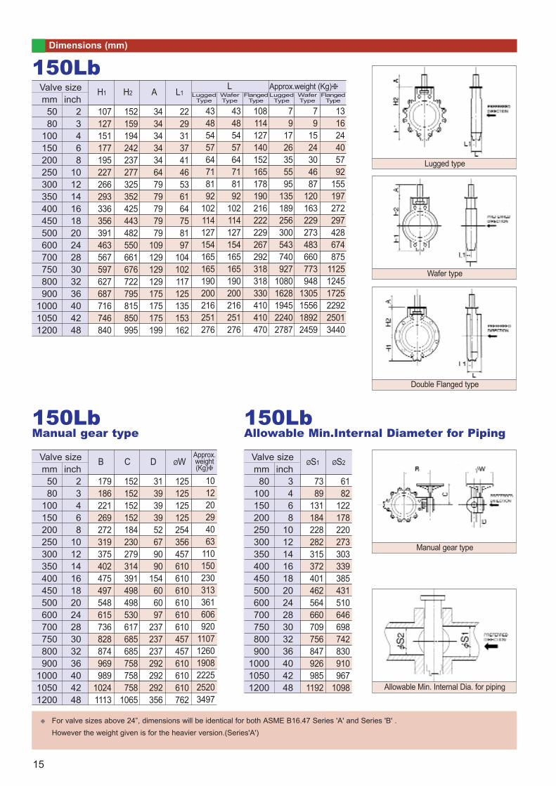
Dimensions (mm)
mm5080
100150200250300350400450500600700750800900
100010501200
inch23468
1012141618202428303236404248
107127151177195227266293336356391463567597627687716746840
H1
152159194242237277325352425443482550661676722795815850995
3434343434647979797979
109129129129175175175199
222931374146536164758197
104102117125135153162
4348545764718192
102114127154165165190200216251276
4348545764718192
102114127154165165190200216251276
108114127140152165178190216222229267292318318330410410470
79
1726355595
135189256300543740927
10801628194522402787
79
1524304687
120163229273483660773948
1305155618922459
131624405792
155197272297428674875
112512451725229225013440
Valve size150Lb
H2 A L1 Lugged Type
Wafer Type
Lugged Type
Wafer Type
Flanged Type
Approx.weight (Kg)
mm5080
100150200250300350400450500600700750800900
100010501200
inch23468
1012141618202428303236404248
179186221269272319375402475497548615736828874969989
10241113
B
152152152152184230279314391498498530617685685758758758
1065
3139393952679090
154606097
237237237292292292356
125125125125254356457610610610610610610457457610610610762
101220294063
110150230313361606920
110712601908222525203497
Valve size
150LbManual gear type
C D ØWApprox.weight(Kg) mm
80100150200250300350400450500600700750800900
100010501200
inch3468
1012141618202428303236404248
7389
131184228282315372401462564660709756847926985
1192
ØS1
6182
122178220273303339385431510646698742830910967
1098
Valve sizeØS2
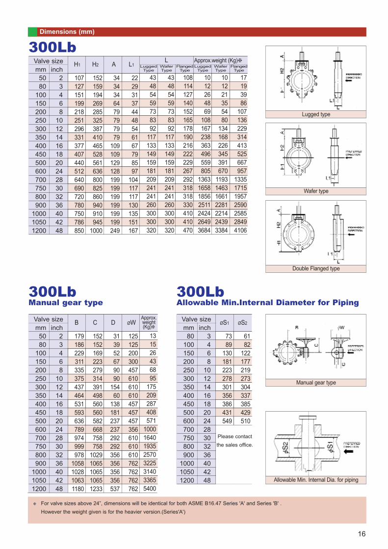
For valve sizes above 24”, dimensions will be identical for both ASME B16.47 Series 'A' and Series 'B' .However the weight given is for the heavier version.(Series'A')
L
Lugged type
Wafer type
Double Flanged type
Manual gear type
Allowable Min. Internal Dia. for piping
Flanged Type
15
Dimensions (mm)
mm5080
100150200250300350400450500600700750800900
100010501200
inch23468
1012141618202428303236404248
107127151199218251296331377407440512640690720780750786850
H1
152159194269285325387410465528561636800825860940910945
1000
3434346479797979
109109129128199199199199199199249
222931374448546167798597
104117117130135151167
43485459738392
117133149159181209241241260300300320
43485459738392
117133149159181209241241260300300320
108114127140152165178190216222229267292318318330410410470
1012264869
108167238363496559805
1363165818562511242426493684
101221355480
134168226345391670
1193146316612281221424393384
17193986
107136229314413525667957
1335171519572590258528494106
Valve size300Lb
H2 A L1 Lugged Type
Wafer Type
Flanged Type
Lugged Type
Wafer Type
Flanged Type
Approx.weight (Kg)
mm5080
100150200250300350400450500600700750800900
100010501200
inch23468
1012141618202428303236404248
179186229311335375437464531593636789974999978
1058102810631180
B
152152169223279314391498560560582668758758
10291065106510651233
313952679090
15460
138181237237292292356356356356537
125125200300457610610610457457457356610610610762762762762
131526436895
175209287408571
10001640193525703225314033655400
Valve size
300LbManual gear type
C D ØWApprox.weight(Kg) mm
80100150200250300350400450500600700750800900
100010501200
inch3468
1012141618202428303236404248
7389
130181223278301356386431549
ØS1
6182
122177219273304337385429510
Valve size
300LbAllowable Min.Internal Diameter for Piping
ØS2
For valve sizes above 24”, dimensions will be identical for both ASME B16.47 Series 'A' and Series 'B' .However the weight given is for the heavier version.(Series'A')
Please contactthe sales office.
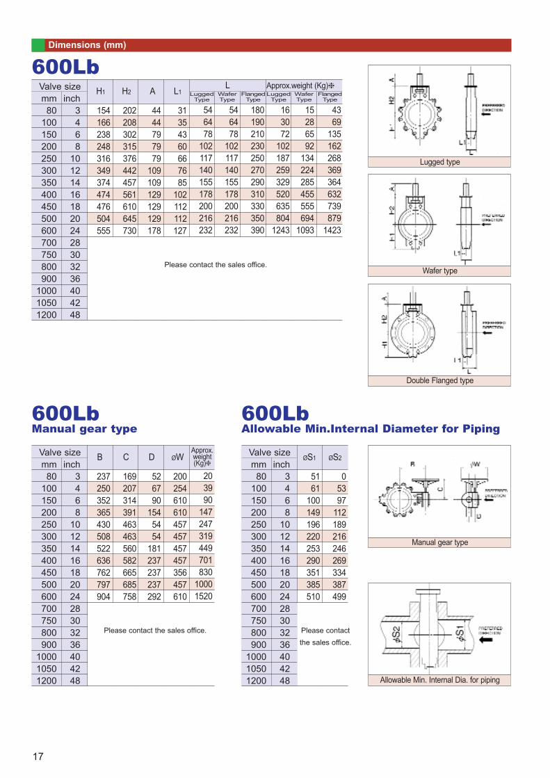
L
Lugged type
Wafer type
Double Flanged type
Manual gear type
Allowable Min. Internal Dia. for piping
16
Dimensions (mm)
mm80
100150200250300350400450500600700750800900
100010501200
inch3468
1012141618202428303236404248
154166238248316349374474476504555
H1
202208302315376442457561610645730
4444797979
109109129129129178
31354360667685
102112112127
546478
102117140155178200216232
546478
102117140155178200216232
180190210230250270290310330350390
163072
102187259329520635804
1243
15286592
134224285455555694
1093
4369
135162268369364632739879
1423
Valve size600Lb
H2 A L1 Lugged Type
Wafer Type
Flanged Type
Lugged Type
Wafer Type
Flanged Type
Approx.weight (Kg)
mm80
100150200250300350400450500600700750800900
100010501200
inch3468
1012141618202428303236404248
237250352365430508522636762797904
B
169207314391463463560582665685758
526790
1545454
181237237237292
200254610610457457457457356457610
203990
147247319449701830
10001520
Valve size
600LbManual gear type
C D ØWApprox.weight(Kg) mm
80100150200250300350400450500600700750800900
100010501200
inch3468
1012141618202428303236404248
5161
100149196220253290351385510
ØS1
05397
112189216246269334387499
Valve size
600LbAllowable Min.Internal Diameter for Piping
ØS2
L
Please contact the sales office.
Please contact the sales office. Please contactthe sales office.
Lugged type
Wafer type
Double Flanged type
Manual gear type
Allowable Min. Internal Dia. for piping
17
Dimensions (mm)
mm100150200250300350400450500600700750800900
100010501200
inch468
1012141618202428303236404248
181238281358383419455503550656
H1
240315360412475512610660685790
647979
109109128129178178199
405260718588
107114127142
80104112135170173210228250275
80104112135170173210228250275
235250310350380400430460490530
43100151256352440663824
10691704
3989
134224298376570691905
1317
93184256425496656834
104412732506
Valve size900Lb
H2 A L1L
Lugged Type
Wafer Type
Flanged Type
Lugged Type
Wafer Type
Flanged Type
Approx.weight (Kg)
mm100150200250300350400450500600700750800900
100010501200
inch468
1012141618202428303236404248
290365414478540587762834859908
B
247331498560560582665723758994
6712360
138181237237292292356
365457610457457457356457610457
59130212329472621857
110013462417
Valve size
900LbManual gear type
C D ØWApprox.weight(Kg) mm
100150200250300350400450500600700750800900
100010501200
inch468
1012141618202428303236404248
2877
136184212239261323376488
ØS1
4180
132186209252270334382488
Valve size
900LbAllowable Min.Internal Diameter for Piping
ØS2
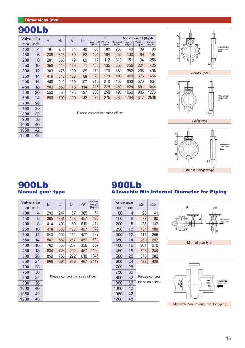
Please contactthe sales office.
Lugged type
Wafer type
Double Flanged type
Manual gear type
Allowable Min. Internal Dia. for piping
18
Please contact the sales office.
Please contact the sales office. Please contactthe sales office.
Dimensions (mm)
mm150200250300350400450500600700750800900
100010501200
inch68
1012141618202428303236404248
257307371414493530591664780
H1
347405510545610655750810950
109109129129178199199199249
8090
100118124133
154.5169.5
204
160180200230250265300340400
160180200230250265300340400
290330390430470510550630710
175237379605849995
147822483021
124202282360589614992
15971792
207406646842
11631476196827824288
Valve size1500Lb
H2 A L1 Lugged Type
Wafer Type
Flanged Type
Lugged Type
Wafer Type
Flanged Type
Approx.weight (Kg)
mm150200250300350400450500600700750800900
100010501200
inch68
1012141618202428303236404248
413470585697784773868928
1100
B
463560582685722
1028102810281146
60181237237292356356356442
457457610457457610610610610
60230181197277714748714
1164
Valve size
1500LbManual gear type
C D ØWApprox.weight(Kg) mm
150200250300350400450500600700750800900
100010501200
inch68
1012141618202428303236404248
ØS1
01185
106134185237257325
00
67105157209238286315
Valve size
1500LbAllowable Min.Internal Diameter for Piping
ØS2
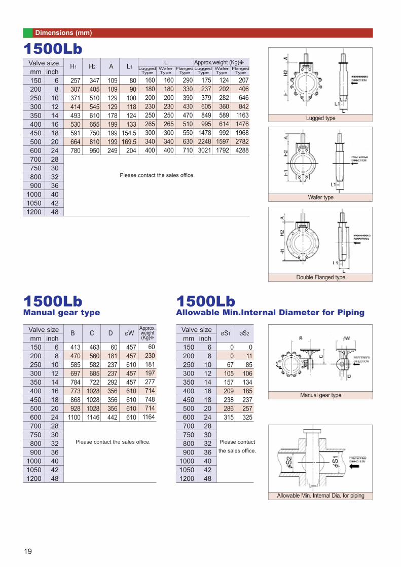
L
Lugged type
Wafer type
Double Flanged type
Manual gear type
Allowable Min. Internal Dia. for piping
19
Please contact the sales office.
Please contact the sales office. Please contactthe sales office.
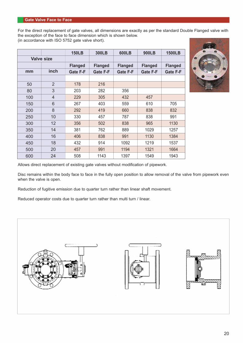
For the direct replacement of gate valves, all dimensions are exactly as per the standard Double Flanged valve withthe exception of the face to face dimension which is shown below.(in accordance with ISO 5752 gate valve short).
Allows direct replacement of existing gate valves without modification of pipework.
Disc remains within the body face to face in the fully open position to allow removal of the valve from pipework evenwhen the valve is open.
Reduction of fugitive emission due to quarter turn rather than linear shaft movement.
Reduced operator costs due to quarter turn rather than multi turn / linear.
Gate Valve Face to Face
150LB
FlangedGate F-F
300LB
FlangedGate F-F
600LB
FlangedGate F-F
900LB
FlangedGate F-F
1500LB
FlangedGate F-F
356432559660787838889991109211941397
457610838838965
10291130121913211549
705832991113012571384153716641943
Valve size
mm
5080100150200250300350400450500600
inch
23468
10121416182024
178203229267292330356381406432457508
2162823054034194575027628389149911143
20
Operating and Maintenance Instructions
INTRODUCTIONThis instruction provides general information on the operation,installation and maintenance of the Tritec triple offset valve. TheTritec valves have been designed and manufactured to operate in anaggressive environment under extremes of temperature and pressurefor long periods and with minimal maintenance.
INSTRUCTIONSPACKING
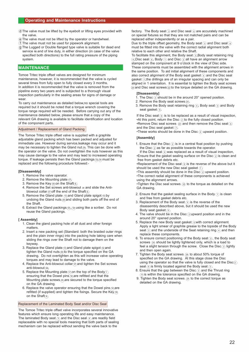
1. All valves will bedespatched with protective covers attached to the flangefaces to protect the gasket sealing surfaces and internal trim.
2. The valve disc is cracked off the seat in the almost closedposition.
3. The Tritec nameplate shown in the picture contains informationsuch as size,pressure class,materials and the unique serial number.
SPARE PARTS
1. When ordering spare parts or discussing matters concerning this valve with the sales office, it is essential to quote the unique Serial Number of the valve which is to be found on the stainless steel nameplate attached to the valve body adjacent to the operator.
TRANSPORTATION
1. Use crates or packing cases for ocean transportation.2. For overland transportation, a covered vehicle is recommended
with protective sheets covering the valves.
STORAGE
1. Store the valves indoors in a cool temperature between –10Þand+60ÞC, humidity at 70% or less.
2. Do not remove the protective covers until ready to install valves.3. Machined ferrous surfaces are protected with an approved rust
preventative. For long periods of storage, apply the rustpreventative once a year to the unpainted surfaces.
4. When storing valves unpacked, take care in protecting valves andactuators from excessive loads. Do not stack unpacked valves.
5. If the valve is for clean gas duty and is being supplied “DEGREASED”,a label is attached stating this and the valvesealed in a polythene covering. It is suggested that the valve is kept packed until it is to be installed in the pipeline.
UNPACKING
1. Unpack valves just before installation.
INSTALLATIONa The valve is designed to seal against bidirectional flow and can
therefore be installed with flow in either direction. Howeverenhanced sealing life will be obtained with upstream flow againstthe shaft side of the disc. This preferred flow direction is shown onthe nameplate attached to the valve body adjacent to the operatorand also on the GA drawing. The valve may be installed in thepipeline with the valve shaft in a horizontal,vertical or intermediateposition.
b Prior to installation,the pipeline must be cleaned from dirt andwelding residues to avoid damage to the valve during operation.
c Ensure that the valve is closed prior to installation to avoid the riskof damage to the sealing surfaces.
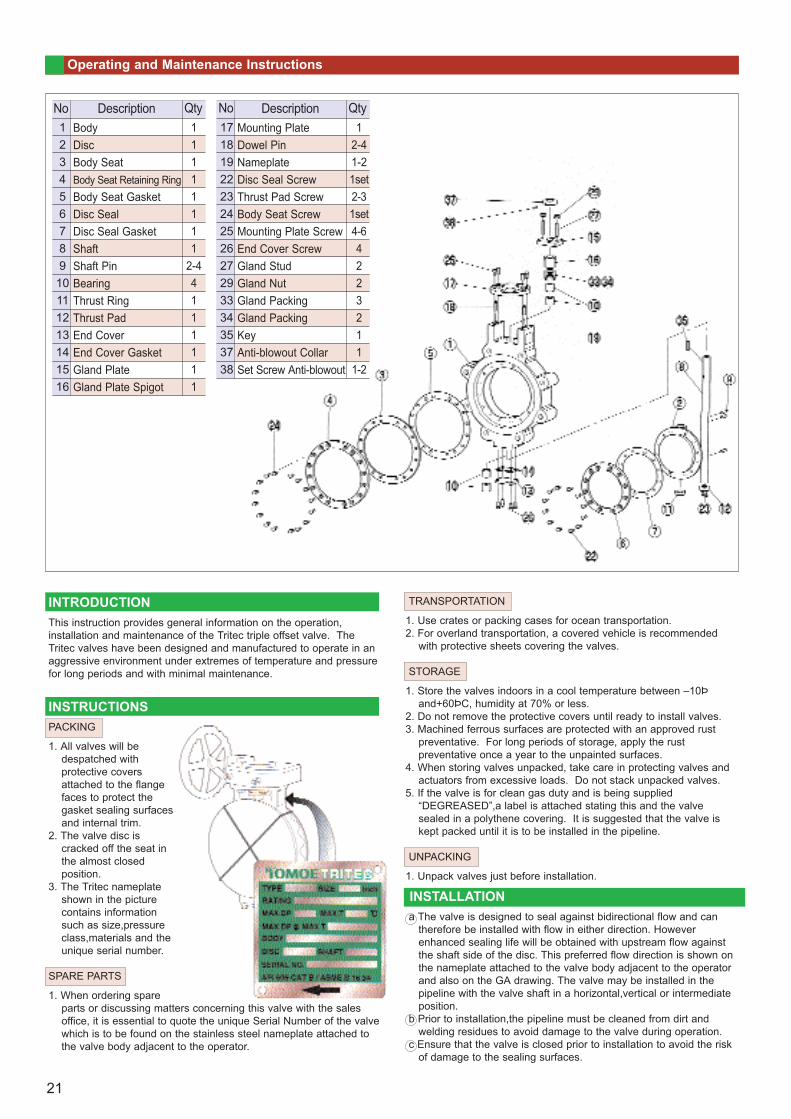
123456789
10111213141516
BodyDiscBody SeatBody Seat Retaining RingBody Seat GasketDisc SealDisc Seal GasketShaftShaft PinBearingThrust RingThrust PadEnd CoverEnd Cover GasketGland PlateGland Plate Spigot
DescriptionNo11111111
2-44111111
Qty171819222324252627293334353738
Mounting PlateDowel PinNameplateDisc Seal ScrewThrust Pad ScrewBody Seat ScrewMounting Plate ScrewEnd Cover ScrewGland StudGland NutGland PackingGland PackingKeyAnti-blowout CollarSet Screw Anti-blowout
DescriptionNo1
2-41-21set2-31set4-64223211
1-2
Qty
21
Operating and Maintenance Instructions
d The valve must be lifted by the eyebolt or lifting eyes provided withthe valve.
e The valve must not be lifted by the operator or handwheel.f The valve must not be used for pipework alignment.g The Lugged or Double flanged type valve is suitable for dead end
service ie.end of line duty, in either direction (in case of the valvespecified both directions) to the full rating pressure of the pipingsystem.
MAINTENANCETomoe Tritec triple offset valves are designed for minimum maintenance, however, it is recommended that the valve is cycled several times from fully open to fully closed every 3 months.In addition it is recommended that the valve is removed from thepipeline every two years and is subjected to a thorough visual inspection particularly in the sealing areas for signs of damage orwear.To carry out maintenance as detailed below,no special tools arerequired but it should be noted that a torque wrench covering thetorque range required will be needed. Before carrying out any of themaintenance detailed below, please ensure that a copy of therelevant GA drawing is available to facilitate identification and locationof the component parts.
Adjustment / Replacement of Gland Packing
The Tomoe Tritec triple offset valve is supplied with a graphiteadjustable gland packing which has been packed and adjusted forimmediate use. However during service,leakage may occur and it may be necessary to tighten the Gland nut 29. This can be done withthe operator on the valve. Do not overtighten the nuts however as thismay cause damage to the valve and may lead to increased operatingtorque. If leakage persists then the Gland packings 33, 34 must bereplaced and the following procedure followed:-
[Disassembly]1. Remove the valve operator.2. Remove the Mounting plate 17.3. Remove the Key 35 on the Shaft 8.4. Remove the Set screws anti-blowout 38 and slide the Anti-
blowout collar 37 off the end of the Shaft 8.5. Remove the Gland plate 15 and Gland plate spigot 16 by
undoing the Gland nuts 29 and sliding both parts off the end ofthe Shaft.
6. Extract the Gland packings 33 , 34 using like a scriber. Do notreuse the Gland packings.
[ Assembly]1. Clean the gland packing hole of all dust and other foreign
matters.2. Insert a new packing set (Standard: both the braided outer rings
and the plain inner rings) into the packing hole taking care whensliding the rings over the Shaft not to damage them on thekeyway.
3. Replace the Gland plate 15 and Gland plate spigot 16 andtighten the Gland nuts 29 to the torque specified on the GAdrawing. Do not overtighten as this will increase valve operatingtorques and may lead to damage to the valve.
4. Replace the Anti-blowout collar 37 and tighten the Set screwsanti-blowout 38.
5. Replace the Mounting plate 17 on the top of the Body 1
ensuring that the Dowel pins 18 are refitted and that theMounting plate screws 25 are secured to the torque specifiedon the GA drawing.
6. Replace the valve operator ensuring that the Dowel pins 18 arerefitted (if supplied) and tighten the fixings. Secure the Key 35
on the Shaft 8.
Replacement of the Laminated Body Seat and/or Disc Seal
The Tomoe Tritec triple offset valve incorporates several innovativefeatures which ensure long operating life and easy maintenance.The laminated Body seat 3 and the Disc seal 6 are readily fieldreplaceable with no special tools meaning that both parts of sealingmechanism can be replaced without sending the valve back to the
factory. The Body seat 3 and Disc seal 6 are accurately machined on special fixtures so that they are not matched pairs and can bereplaced either independently or as a pair.Due to the triple offset geometry, the Body seat 3 and Disc seal 6
must be fitted into the valve with the correct radial alignment both relative to each other and relative the Shaft.To facilitate this alignment, the Body seat 3 ,Body seat retaining ring 4 ,Disc seal 6 , Body 1 and Disc 2 all have an alignment arrow
stamped on the component at 9 o’clock in the view of Disc side.These components must be assembled with the alignment arrows inthe same position. To aid initial alignment of these components andalso correct alignment of the Body seat gasket 5 and the Disc sealgasket 7 ,the drillings are of an irregular spacing and can only bealigned in 1 orientation. It is essential to tighten the Body seat screws24 and Disc seal screws 22 to the torque detailed on the GA drawing.
[Disassembly]1. The Disc 2 should be in the around 20° opened position.2. Remove the Body seat screws 24 .3. Remove the Body seat retaining ring 4 , Body seat 3 and Body
seat gasket 5 .
If the Disc seal 6 is to be replaced as a result of visual inspection,•At this point, return the Disc 2 to the fully closed position.•Remove Disc seal screws 22 and then remove the Disc seal 6
and the Disc seal gasket 7 .•These works should be done in the Disc 2 upward position.
[Assembly]
1. Ensure that the Disc 2 is in a central float position by pushingthe Disc 2 as far as possible towards the operator.If the Disc seal 6 was replaced as a result of visual inspection,
•Ensure that the gasket sealing surface on the Disc 2 is clean andfree from gasket debris etc.
•Replacement of the Disc seal 6 is the reverse of the above but itshould be used the new Disc seal gasket 7 .•This assembly should be done in the Disc 2 upward position.•The correct radial alignment of these components is achievedusing the alignment arrows.•Tighten the Disc seal screws 22 to the torque as detailed on theGA drawing.
2. Ensure that the gasket sealing surface in the Body 1 is cleanand free from gasket debris etc.
3. Replacement of the Body seat 3 is the reverse of thedisassembly described above, but it should be used the newBody seat gasket 5 .
4. The valve should be in the Disc 2 upward position and in thearound 20° opened position.
5. Replace the new Body seat gasket 5 with correct alignment.Apply a light smear of graphite grease to the topside of the Bodyseat 3 and the underside of the Seat retaining ring 4 and thenreplace these components.
6. To ensure correct positioning of the Body seat 3 , the Body seatscrews 24 should be lightly tightened only, which is a load tofeel a slight tension through the screw. Close the Disc 2 lightlyand then open again.
7. Tighten the Body seat screws 24 to about 50% torque ofspecified on the GA drawing. At this stage close the Disc using the operator so that the valve is fully closed and the Disc 2
seal 6 is firmly located against the Body seat 3 .8. Ensure that the gap between the Disc 2 and the Thrust ring
11 is within the tolerance specified on the GA drawing.9. Tighten the Body seat screws 24 to the correct torque as
detailed on the GA drawing.
22