triple offset butterfly valves - flowserve corporation | home · pdf fileflowserve tx2...
TRANSCRIPT
FCD-DVENIM0400-00
Installation, Operation, and Maintenance
Breaking the Barriers
Flowserve TX2
Triple Offset Butterfly Valves

Flow Control Division
2
TABLE OF CONTENTS
SECTION TITLE PAGE
FOREWORD 2
I THEORY OF OPERATION 3
II PRELIMINARY PRECAUTIONS 3
III INSPECTION 4
IV TOOL REQUIREMENT 4
V STORAGE 5
VI INSTALLATION 5
VII STEPS OF INSTALLATION 5
VIII FLANGE CONNECTING AND BOLTING 7
IX REMOVAL PROCEDURE 8
X LUBRICATION SCHEDULE 8
XI STUFFING BOX MAINTENANCE PROCEDURE 8
XII CHANGE OF DISC AND BODY SEAT 11
XIII CHANGE OF GASKET 14
XIV ASSEMBLY AND DISASSEMBLY 14
XV PARTS AND SERVICE 16
XVI TROUBLESHOOTING GUIDE 17
XVII CAUTIONS 18
XVIII PARTS LIST AND MARKINGS 21 FOREWORD
Flowserve Corporation, Flow Control Division, has established this Installation, Operating and
maintenance Manual to facilitate field installation, operation and repair of Flowserve TX2 Triple
Offset Butterfly Valves
It is recommended that questions or concerns involving the processes described in this manual be
directed to the local Sales Representative of Flowserve Corporation. Only Flowserve
replacement repair parts should be used. Part numbers referenced in the following sections are
available from Flowserve Corporation, Flow Control Division.
Flow Control Division
3
SECTION I
THEORY OF OPERATION
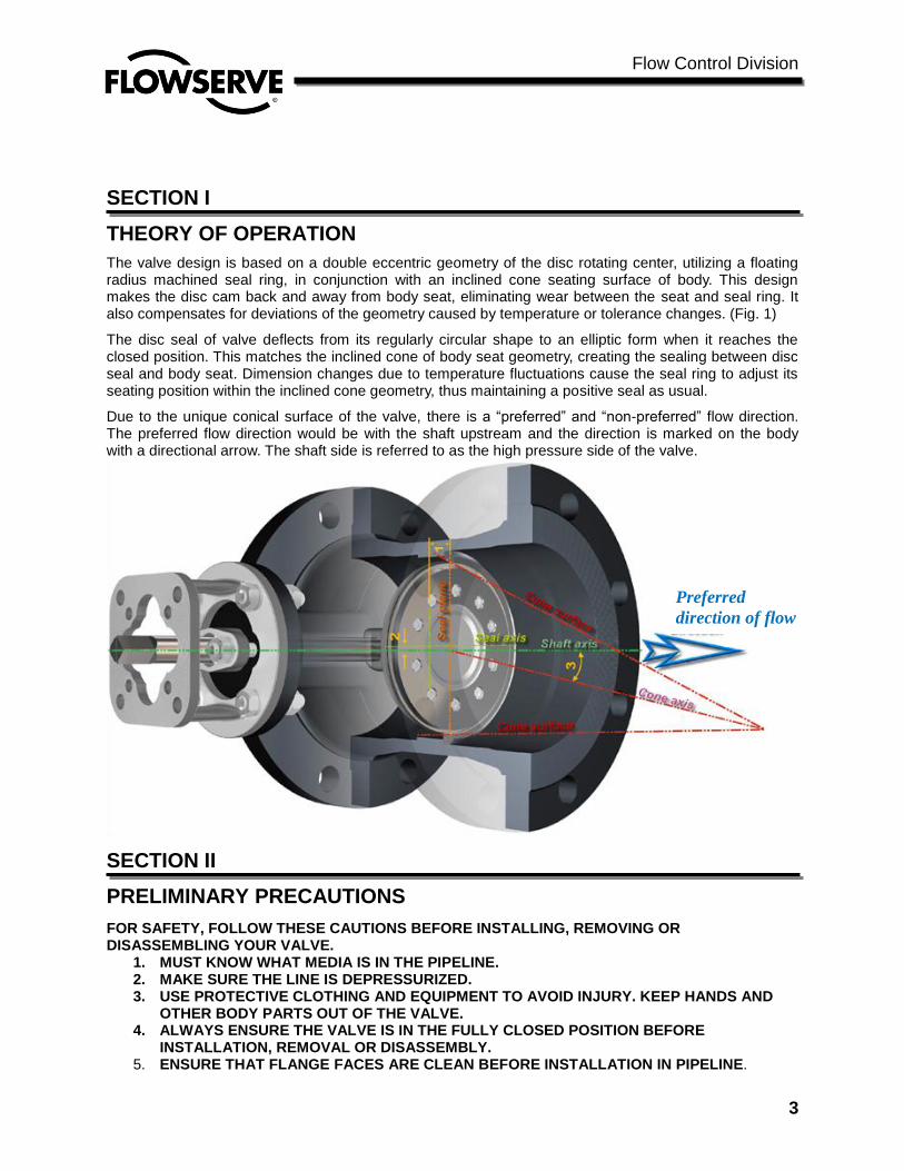
The valve design is based on a double eccentric geometry of the disc rotating center, utilizing a floating radius machined seal ring, in conjunction with an inclined cone seating surface of body. This design makes the disc cam back and away from body seat, eliminating wear between the seat and seal ring. It also compensates for deviations of the geometry caused by temperature or tolerance changes. (Fig. 1)
The disc seal of valve deflects from its regularly circular shape to an elliptic form when it reaches the closed position. This matches the inclined cone of body seat geometry, creating the sealing between disc seal and body seat. Dimension changes due to temperature fluctuations cause the seal ring to adjust its seating position within the inclined cone geometry, thus maintaining a positive seal as usual.
Due to the unique conical surface of the valve, there is a “preferred” and “non-preferred” flow direction. The preferred flow direction would be with the shaft upstream and the direction is marked on the body with a directional arrow. The shaft side is referred to as the high pressure side of the valve.
SECTION II
PRELIMINARY PRECAUTIONS
FOR SAFETY, FOLLOW THESE CAUTIONS BEFORE INSTALLING, REMOVING OR DISASSEMBLING YOUR VALVE.
1. MUST KNOW WHAT MEDIA IS IN THE PIPELINE. 2. MAKE SURE THE LINE IS DEPRESSURIZED. 3. USE PROTECTIVE CLOTHING AND EQUIPMENT TO AVOID INJURY. KEEP HANDS AND
OTHER BODY PARTS OUT OF THE VALVE. 4. ALWAYS ENSURE THE VALVE IS IN THE FULLY CLOSED POSITION BEFORE
INSTALLATION, REMOVAL OR DISASSEMBLY. 5. ENSURE THAT FLANGE FACES ARE CLEAN BEFORE INSTALLATION IN PIPELINE.
Preferred
direction of flow
Flow Control Division
4
SECTION III
INSPECTION
1. Before installation of the valve into the piping system, visually inspect the valve to determine if any damage has occurred during shipping. Particularly, inspect the actuator, shaft, valve interior, valve body and flanges. For proper operation of the valves, the seat and disc seal must be undamaged and free of foreign material. If other than superficial damage is discovered, contact Flowserve immediately, indicating the location and extent of the damage found.
2. If it is necessary to clean the valve, use a soft cloth and mineral spirits, or an equivalent
solvent. All rust preventive should be removed before installing your valve.
SECTION IV
TOOL REQUIREMENT
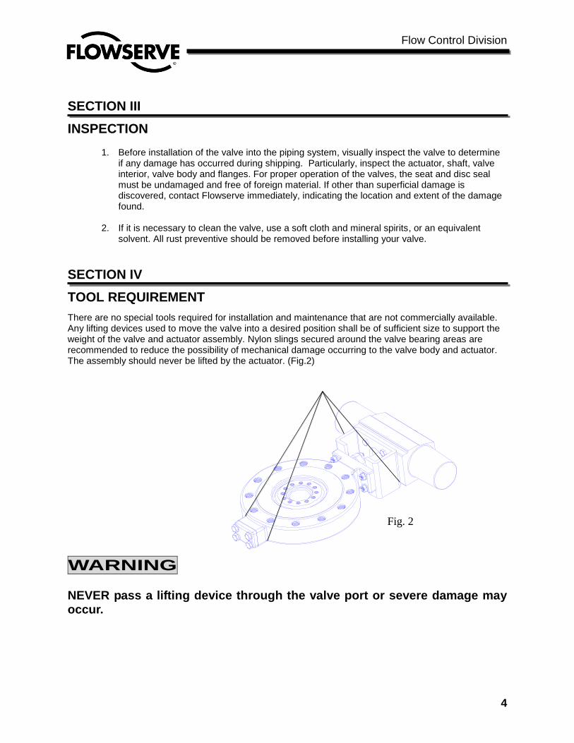
There are no special tools required for installation and maintenance that are not commercially available. Any lifting devices used to move the valve into a desired position shall be of sufficient size to support the weight of the valve and actuator assembly. Nylon slings secured around the valve bearing areas are recommended to reduce the possibility of mechanical damage occurring to the valve body and actuator. The assembly should never be lifted by the actuator. (Fig.2)
WARNING
NEVER pass a lifting device through the valve port or severe damage may occur.
Fig. 2
Flow Control Division
5
SECTION V
STORAGE
When the valve is not put into immediate service, it is required that the valve be stored in a heated building that is
fire resistant, weather tight and well ventilated. Storage area shall be situated and constructed so that it will not be
subject to flooding or the presence of any corrosive chemicals. Flowserve recommends that all valve actuators be
cycled approximately every 60 days or as required by the manufacturer of the actuation system. Any spare parts for
the valve shall be stored in the original packaging and under the same conditions as the valve will be stored. For
storage greater than 4 months, the storage container should be inspected every four (4) months to ensure it is in good
condition, and any additional protective coverings or materials are in working order. Ensure all parts are plugged,
and bare metal is covered with a suitable rust inhibitor.
SECTION VI
INSTALLATION
The valve must be installed so that pipeline stresses are not transmitted to the valve body. Despite its solid
manufacture, such stress may affect valve operation. If pipeline stresses are severe, they should be cushioned by
expansion joints or compensators. If supports are necessary for the valve, they should only support the dead weight
of the valve and should not serve as base points for the pipeline.
SECTION VII
STEPS OF INSTALLATION
7.1. All valve s must be in full closed position during installation or removal. It is not necessary to torque
seat the valve, but the disc travel must be restricted to prevent damage.
7.2. Please be sure there is no foreign material and that it is clean inside of the pipe and valve.
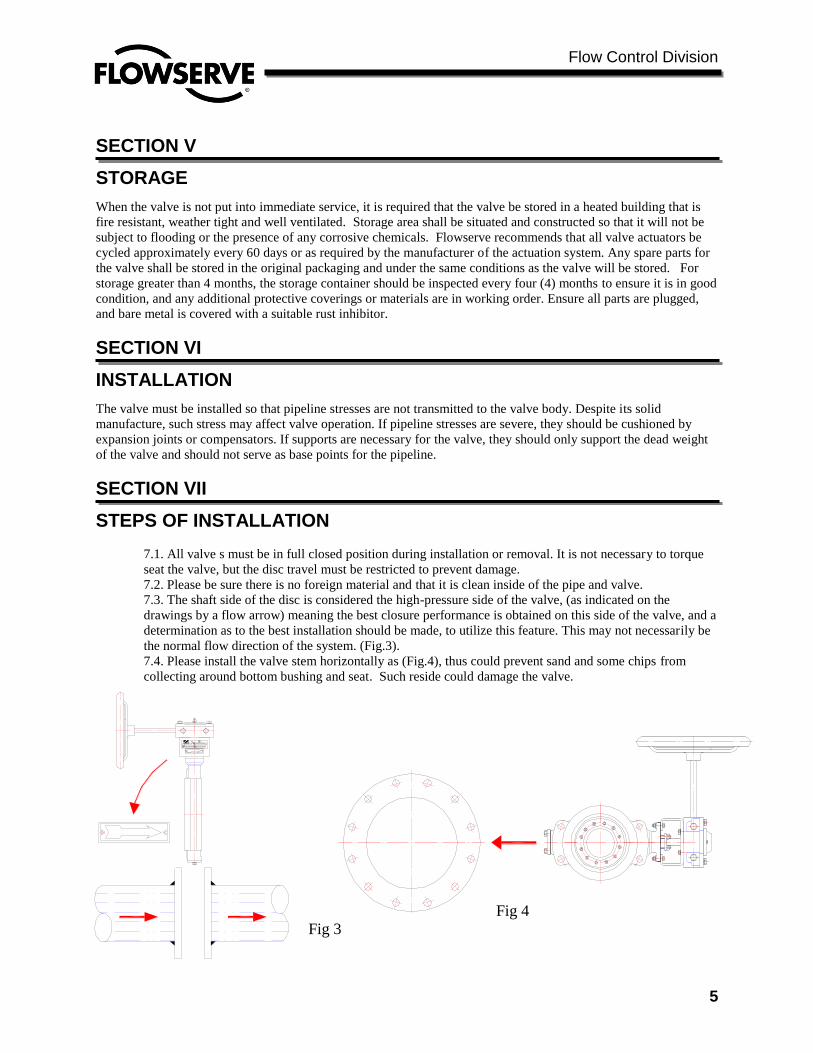
7.3. The shaft side of the disc is considered the high-pressure side of the valve, (as indicated on the
drawings by a flow arrow) meaning the best closure performance is obtained on this side of the valve, and a
determination as to the best installation should be made, to utilize this feature. This may not necessarily be
the normal flow direction of the system. (Fig.3).
7.4. Please install the valve stem horizontally as (Fig.4), thus could prevent sand and some chips from
collecting around bottom bushing and seat. Such reside could damage the valve.
Fog 4
Fig 4
Fig 3
Fig 4
Flow Control Division
6
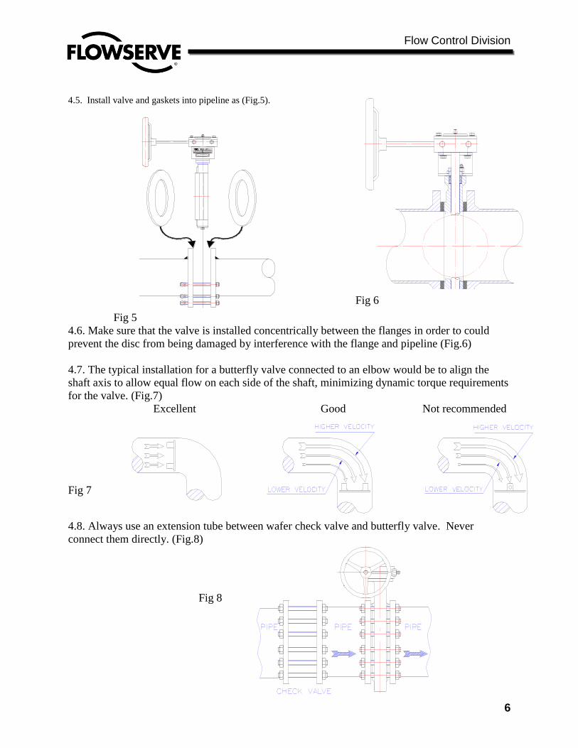
4.5. Install valve and gaskets into pipeline as (Fig.5).
Fig 5
4.6. Make sure that the valve is installed concentrically between the flanges in order to could
prevent the disc from being damaged by interference with the flange and pipeline (Fig.6)
4.7. The typical installation for a butterfly valve connected to an elbow would be to align the
shaft axis to allow equal flow on each side of the shaft, minimizing dynamic torque requirements
for the valve. (Fig.7)
Excellent Good Not recommended
Fig 7
4.8. Always use an extension tube between wafer check valve and butterfly valve. Never
connect them directly. (Fig.8)
Fig 8
Fig 6

Flow Control Division
7
SECTION VIII
FLANGE CONNECTING & BOLTING
8.1. Keep valve protection boards until installation.
8.2. Make sure the material and size of gaskets could be suitable for the service. Ensure that the faces of flange and
valve are smooth and flat. Sandpaper the faces if there are any defects.
8.3. Check that all the bolts and nuts are in good condition.
8.4. Apply lubricant such as Molybdenum to all the bolts and nuts before fixing them.
8.5. The pipe support(s) may now be required to be partially disengaged. A determination as to pipe flange
alignment and space between the pipe flange and the valve face must be made at this time. The optimum spacing
would be such as to only allow the flange gasket to be installed, at the maximum, and the flange bolt holes would be
concentric.
8.6. The opposite connecting pipe flange face may not be more than 1/4 inch away from the valve flange face.
Alternate methods of alignment, other than using the flange bolts, must be utilized to conform with this requirement.
8.7. Install all studs, maintaining uniform clearance between the studs and the mating bolt holes. Additionally the
studs spanning the valve assembly should not contact the valve body.
8.8. Seat the flange by alternate tightening of four equally-spaced flange bolts no more than 1/4 turn per bolt, until
the flange faces seat. During this operation, it is advisable to continually check the relative distance between the
flange faces. Torque the bolts to approximately 25% of the final torque value (see table 1).
8.9. Inspect the remaining bolts and assure correct alignment. Tighten to the same level as the first four bolts.
8.10. Complete the tightening of all flange bolting in a minimum of four increments to the final determined torque
value.
8.11. Test cycle the valve to be sure that there is no interference or binding.
12. Maximum Torque of Flange Bolt
Bolt size Torque
(ft-lb) (Nm)
5/8” (M16) 110 150
3/4” (M20) 200 270
7/8” (M22) 320 434
1” (M26) 480 650
1-1/8”(M28) 600 815
1-1/4”(M32) 840 1140
Table 1.
※Actual torque shall depend on gasket
type, consult gasket manufacturer.
BOLT TIGHTENING SEQUENCE (Fig.9)
Flow Control Division
8
SECTION IX
REMOVAL PROCEDURE To remove your valve from the pipeline, please follow these simple steps:
Ensure that the valve is in the closed position.
Ensure that the line is depressurized.
Use protective clothing and equipment to prevent injury.
If your valve is equipped with a fail-open actuator, manually close the valve or disconnect the actuator then close
the valve before removal.
Attach nylon slings to the body shoulders of the valve and around the body of the actuator.
Remove the bolts holding the valve to the pipeline flanges.
SECTION X
LUBRICATION SCHEDULE Flowserverecommends that your valve be inspected at least every three months to determine lubrication and other
maintenance requirements dependign upon your specific service conditions.
SECTION XI
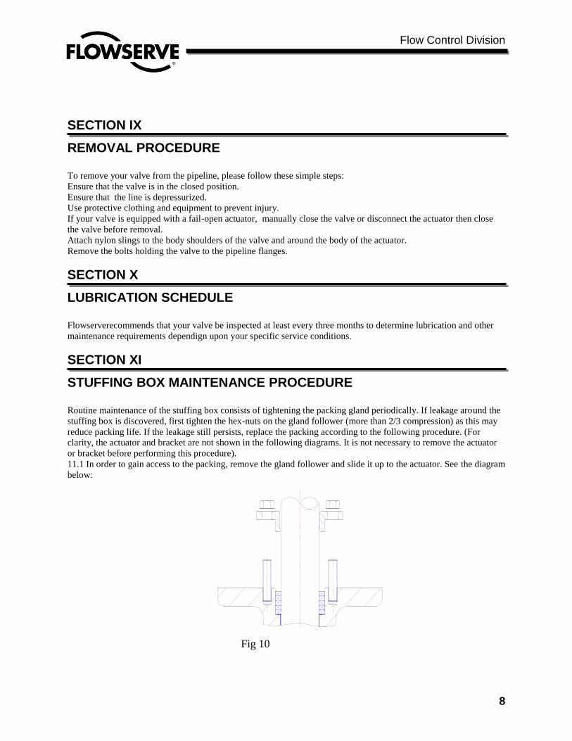
STUFFING BOX MAINTENANCE PROCEDURE Routine maintenance of the stuffing box consists of tightening the packing gland periodically. If leakage around the
stuffing box is discovered, first tighten the hex-nuts on the gland follower (more than 2/3 compression) as this may
reduce packing life. If the leakage still persists, replace the packing according to the following procedure. (For
clarity, the actuator and bracket are not shown in the following diagrams. It is not necessary to remove the actuator
or bracket before performing this procedure).
11.1 In order to gain access to the packing, remove the gland follower and slide it up to the actuator. See the diagram
below:
Fig 10
Flow Control Division
9
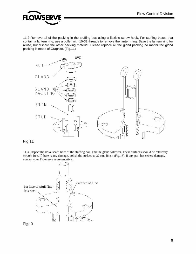
11.2 Remove all of the packing in the stuffing box using a flexible screw hook. For stuffing boxes that contain a lantern ring, use a puller with 10-32 threads to remove the lantern ring. Save the lantern ring for reuse, but discard the other packing material. Please replace all the gland packing no matter the gland packing is made of Graphite. (Fig.11)
Fig.11
11.3 Inspect the drive shaft, bore of the stuffing box, and the gland follower. These surfaces should be relatively
scratch free. If there is any damage, polish the surface to 32 rms finish (Fig.13). If any part has severe damage,
contact your Flowserve representative..
Fig.13
Flow Control Division
10
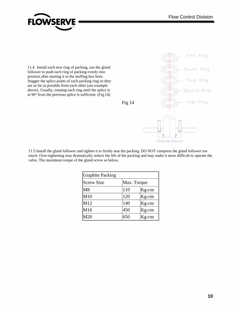
11.5 Install the gland follower and tighten it to firmly seat the packing. DO NOT compress the gland follower too
much. Over-tightening may dramatically reduce the life of the packing and may make it more difficult to operate the
valve. The maximum torque of the gland screw as below,
Graphite Packing
Screw Size Max. Torque
M8 110 Kg-cm
M10 120 Kg-cm
M12 140 Kg-cm
M16 450 Kg-cm
M20 650 Kg-cm
11.4 Install each new ring of packing, use the gland
follower to push each ring of packing evenly into
position after starting it in the stuffing box bore.
Stagger the splice-joints of each packing ring so they
are as far as possible from each other (see example
above). Usually, rotating each ring until the splice is
at 90° from the previous splice is sufficient. (Fig.14)
Fig 14
Flow Control Division
11
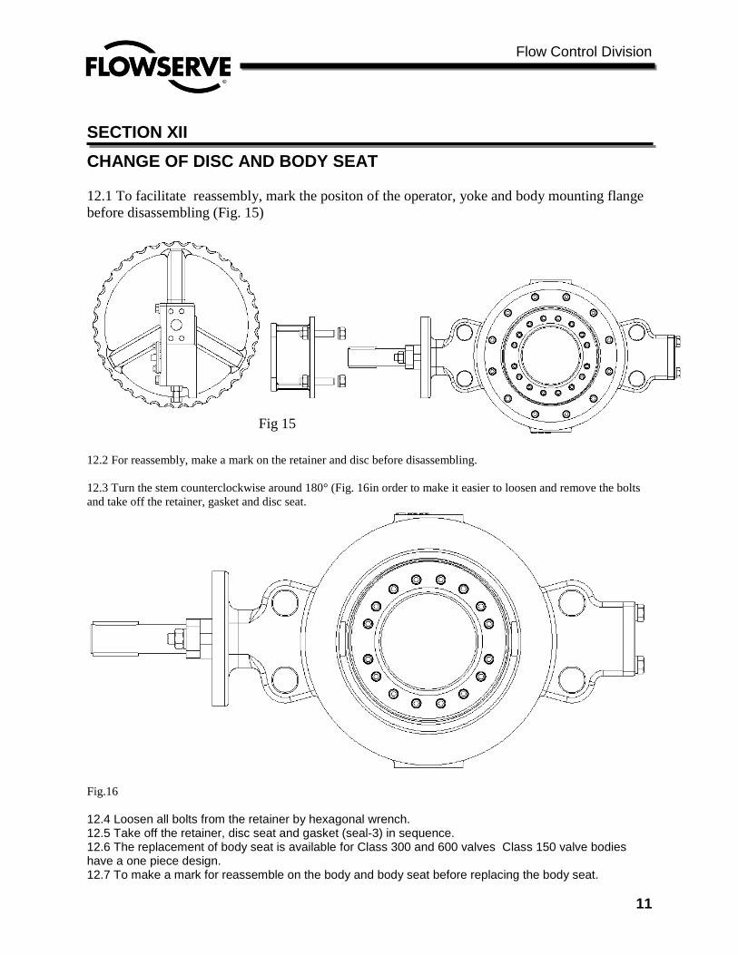
SECTION XII
CHANGE OF DISC AND BODY SEAT
12.1 To facilitate reassembly, mark the positon of the operator, yoke and body mounting flange
before disassembling (Fig. 15)
12.2 For reassembly, make a mark on the retainer and disc before disassembling.
12.3 Turn the stem counterclockwise around 180° (Fig. 16in order to make it easier to loosen and remove the bolts
and take off the retainer, gasket and disc seat.
Fig.16
12.4 Loosen all bolts from the retainer by hexagonal wrench. 12.5 Take off the retainer, disc seat and gasket (seal-3) in sequence. 12.6 The replacement of body seat is available for Class 300 and 600 valves Class 150 valve bodies have a one piece design. 12.7 To make a mark for reassemble on the body and body seat before replacing the body seat.
Fig 15
Flow Control Division
12
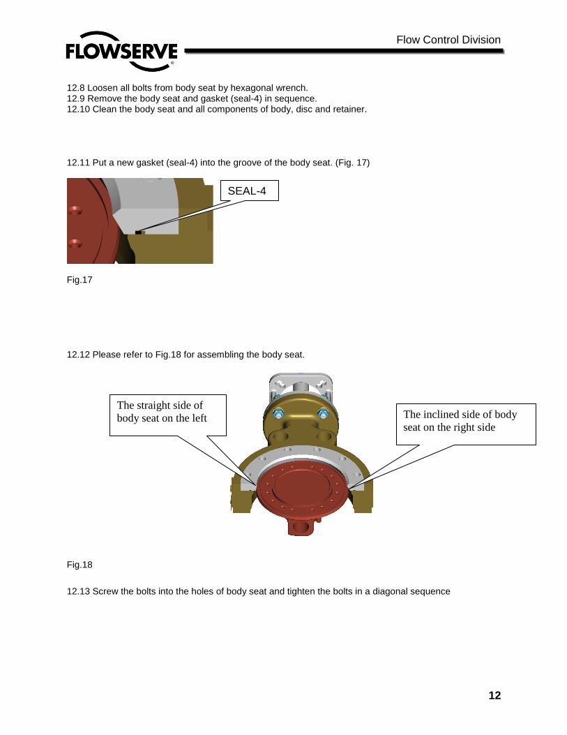
12.8 Loosen all bolts from body seat by hexagonal wrench. 12.9 Remove the body seat and gasket (seal-4) in sequence. 12.10 Clean the body seat and all components of body, disc and retainer. 12.11 Put a new gasket (seal-4) into the groove of the body seat. (Fig. 17)
Fig.17 12.12 Please refer to Fig.18 for assembling the body seat.
Fig.18
12.13 Screw the bolts into the holes of body seat and tighten the bolts in a diagonal sequence
SEAL-4
The inclined side of body
seat on the right side
The straight side of
body seat on the left
Flow Control Division
13
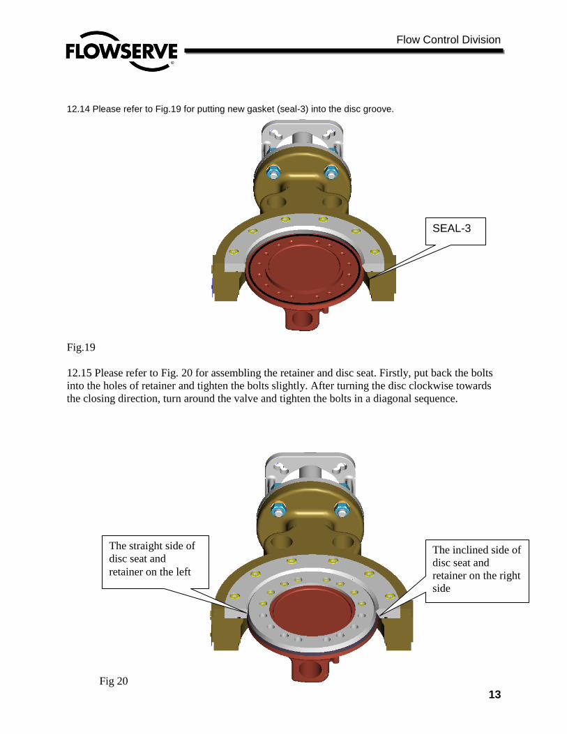
12.14 Please refer to Fig.19 for putting new gasket (seal-3) into the disc groove.
Fig.19
12.15 Please refer to Fig. 20 for assembling the retainer and disc seat. Firstly, put back the bolts
into the holes of retainer and tighten the bolts slightly. After turning the disc clockwise towards
the closing direction, turn around the valve and tighten the bolts in a diagonal sequence.
Fig 20
SEAL-3
The inclined side of
disc seat and
retainer on the right
side
The straight side of
disc seat and
retainer on the left

Flow Control Division
14
SECTION XIII
CHANGE OF GASKET
13.1 Loosen and remove the bolts from the body bottom cover and take off the bottom cover and
gasket (seal-2). (Fig. 21)
13.2 Replace the gasket (seal-2) with a new one, put back the bottom cover and the bolts, and
tighten the bolts in a diagonal sequence.
Fig.21
SECTION XIV
ASSEMBLY AND DISASSEMBLY 14.1 Assembly
14.1.1. Clean all valve components and make sure that they are free of oil, grease and dust.
14.1.2. Inspect all components for damage before starting to assemble. Look especially for
damage to the disc seal ring and body seat surface, and wear in the bearing areas of the body and
drive shaft.
14.1.3. Insert the disc into the body inner diameter, holding it at the open position. The disc is
double eccentric and closes clockwise. Ensure the eccentricities of the disc and body will be in
the same position when closed.
14.1.4. Insert the drive shaft bearing and bottom shaft bearing into the body.
14.1.5. Open the disc nearly 180°. In this position it is possible to assemble the seal o-ring, the
seal ring and the seal ring retainer.
SEAL-2
Flow Control Division
15
14.1.6. Position the seal o-ring on the disc, then place the seal ring onto the disc with the larger
diameter of the outer radius edge on the side of the disc hub.
14.1.7. Place the seal ring retainer onto the disc. Insert the lock washers and hex-socket cap
screws into the seal ring retainer and lightly tighten them.
14.1.8. Turn the disc clockwise into the closed position, then tighten the hex-socket cap screws
fully.
14.1.9. Insert the packing retainer and packing rings into the drive side packing gland.
14.1.10. Insert the studs into the threaded holes in the drive side packing gland.
14.1.11. Install the packing follower and tighten it into position with the hex nuts. Do not tighten
one hex nut further than the other.
14.1.12. Install the blind flange with gasket and tighten it into position with the hex-socket cap
screws.
14.1.13. The valve is now ready for actuator mounting. The disc is held quite securely in
position, so the actuator may be pushed onto the shaft then moved to the desired fail position.
Please consult the actuator’s literature for further details.
14.2. Disassembly
14.2.1. Place the valve on a bench or other suitable working surface with the drive shaft side of
the valve up. Remove the actuator and actuator bracket from the valve.
14.2.2. Separate the packing follower by removing the hex-nuts from the studs, then remove the
studs.
14.2.3. Remove the packing using a flexible screw-hook.
14.2.4. Remove the packing retainer, being careful not to damage the finish of the packing gland
bore or the drive shaft.
14.2.5. Open disc at 90°, then separate the seal ring retainer, seal ring, and o-ring from the disc.
14.2.6. Close the disc, and support the opposite side of the disc to prevent damage to the shafts
while drilling out the pins.
14.2.7. Pull out the stem and remove the disc from the body. Disassembly is now complete.
Flow Control Division
16
SECTION XV
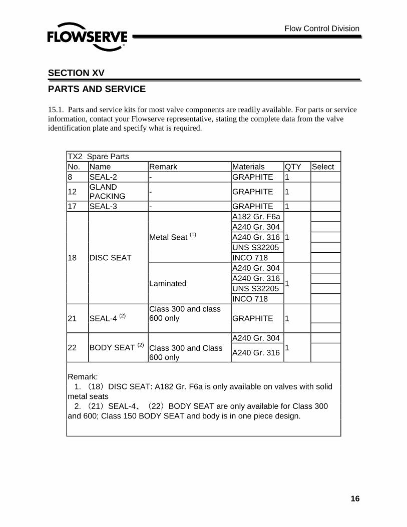
PARTS AND SERVICE 15.1. Parts and service kits for most valve components are readily available. For parts or service
information, contact your Flowserve representative, stating the complete data from the valve
identification plate and specify what is required.
TX2 Spare Parts
No. Name Remark Materials QTY Select
8 SEAL-2 - GRAPHITE 1
12 GLAND PACKING
- GRAPHITE 1
17 SEAL-3 - GRAPHITE 1
18 DISC SEAT
Metal Seat (1)
A182 Gr. F6a
1
A240 Gr. 304
A240 Gr. 316
UNS S32205
INCO 718
Laminated
A240 Gr. 304
1
A240 Gr. 316
UNS S32205
INCO 718
21 SEAL-4 (2)
Class 300 and class 600 only GRAPHITE 1
22 BODY SEAT (2)
A240 Gr. 304
1
Class 300 and Class 600 only
A240 Gr. 316
Remark:
1. (18)DISC SEAT: A182 Gr. F6a is only available on valves with solid
metal seats
2. (21)SEAL-4、(22)BODY SEAT are only available for Class 300
and 600; Class 150 BODY SEAT and body is in one piece design.

Flow Control Division
17
SECTION XVI
TROUBLESHOOTING GUIDE In the event of valve difficulties you may try the following procedures before contacting Flowserve. If your valve doesn’t operate properly before or after trying these trouble- shooting ideas, you may contact your Flowserve representative for assistance . 16.1 LEAKAGE FROM STUFFING BOX If leakage around the stuffing box is discovered, first tighten the nuts on the gland follower to stop the leakage. Do not over tighten the gland follower (more than 2/3 compression) as this may reduce packing life. If the leakage still persists, replace the packing according to the procedure in the “ Stuffing Box Maintenance Procedure” section. 16.2 LEAKAGE BETWEEN SEAL RING AND SEAT Inspect Seal Ring for damage or excessive wear. If necessary, the Seal Ring may be lightly hand polished using wet 400grit sandpaper. If leakage persists, or if not damage is evident, open and close the valve 4 to 5 times, shutting it TIGHTLY each time. Re-check for leakage. If the valve still leaks in this area, strike the back of the disc near the perimeter with a lead bar (or similar soft headed instrument to prevent damaging the disc) to firmly seat the disc. Be sure to apply the force in a direction that will assist in closing, not opening the disc. If leakage in this area persists, check the Seal Ring for roundness. If the Seal Ring is out of round greater than its diameter times 1.00 x 10⁻³ (D x 0.001), orient the seal ring with the longest dimension perpendicular to the valve shaft, and re-test for leakage. If leakage still preexists, contact Flowserve for repair. (Fig.22) 16.3. LEAKAGE BETWEEN SEAL RING RETAINER AND SEAL RING (19) OR DISC Firstly, ensure the bolts of retainer (20) were tightened in a diagonal sequence. If leakage persists, please disassemble the retainer (19) and inspect the gasket (17). If found to be damaged, please replace the gasket. (Fig. 22)
Fig.22
16.4. LEAKAGE BETWEEN BODY SEAT AND BODY (LOCKED DESIGN).
Firstly, ensure the bolts of body seat (22) were tightened in a diagonal sequence. If leakage persists, please
disassemble the body seat (23) and inspect the gasket (21). If found the damage, please replace the gasket. (Fig. 22)
16.2
16.3
20
19
17
23
22
21
16.4
Flow Control Division
18
SECTION XVII
CAUTIONS 17.1. Application:
17.1.1. The valves are not suitable for a flows containing metal chips, which could hurt the valve seats. 17.1.2. Be sure the valve materials are suitable for the process fluid, especially if the fluid is corrosive. 17.1.3. Be sure the valves are suitable for the pressure and temperature ratings of the connecting flanges.
17.1.4. The valve service temperature range:-196 ~ 760℃. (-321~1400°F)
17.1.5. Maximum working pressure can not be higher than the design pressure of the valve.
17.2. Installation:
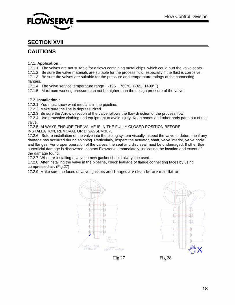
17.2.1 You must know what media is in the pipeline. 17.2.2 Make sure the line is depressurized. 17.2.3 Be sure the Arrow direction of the valve follows the flow direction of the process flow. 17.2.4 Use protective clothing and equipment to avoid injury. Keep hands and other body parts out of the valve. 17.2.5. ALWAYS ENSURE THE VALVE IS IN THE FULLY CLOSED POSITION BEFORE INSTALLATION, REMOVAL OR DISASSEMBLY. 17.2.6. Before installation of the valve into the piping system visually inspect the valve to determine if any damage has occurred during shipping. Particularly, inspect the actuator, shaft, valve interior, valve body and flanges. For proper operation of the valves, the seat and disc seal must be undamaged. If other than superficial damage is discovered, contact Flowserve. immediately, indicating the location and extent of the damage found. 17.2.7 When re-installing a valve, a new gasket should always be used. . 17.2.8 After installing the valve in the pipeline, check leakage of flange connecting faces by using compressed air. (Fig.27)
17.2.9 Make sure the faces of valve, gaskets and flanges are clean before installation.
Fig.27 Fig.28
X
Flow Control Division
19
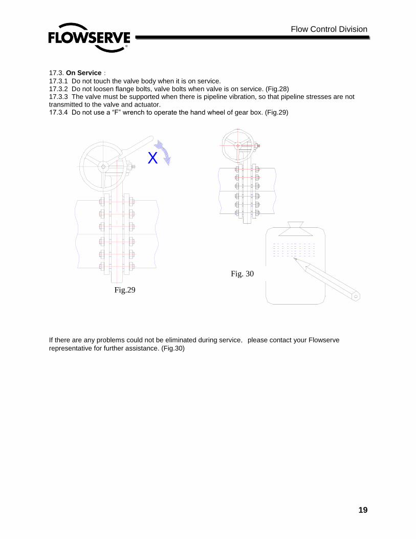
17.3. On Service:
17.3.1 Do not touch the valve body when it is on service. 17.3.2 Do not loosen flange bolts, valve bolts when valve is on service. (Fig.28) 17.3.3 The valve must be supported when there is pipeline vibration, so that pipeline stresses are not transmitted to the valve and actuator. 17.3.4 Do not use a “F” wrench to operate the hand wheel of gear box. (Fig.29)
Fig.29 Fig.30
If there are any problems could not be eliminated during service,please contact your Flowserve
representative for further assistance. (Fig.30)
X
Fig. 30
Flow Control Division
20
17.1 Maintenance
17.4.1 Maintenance personnel should be trained before doing the repair.
17.4.2. Do not replace the gaskets when the pipeline is in operation or is pressurized.
17.4.3. Repaint the valve when it rusts.
17.4.4. If finding the parts of valve has been corroded, please replace with a new one.
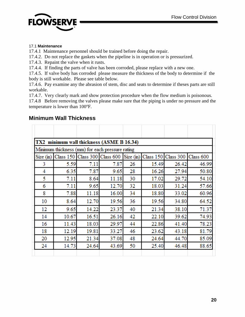
17.4.5. If valve body has corroded please measure the thickness of the body to determine if the
body is still workable. Please see table below.
17.4.6. Pay examine any the abrasion of stem, disc and seats to determine if theses parts are still
workable.
17.4.7. Very clearly mark and show protection procedure when the flow medium is poisonous.
17.4.8 Before removing the valves please make sure that the piping is under no pressure and the
temperature is lower than 100℉.
Minimum Wall Thickness
Flow Control Division
21
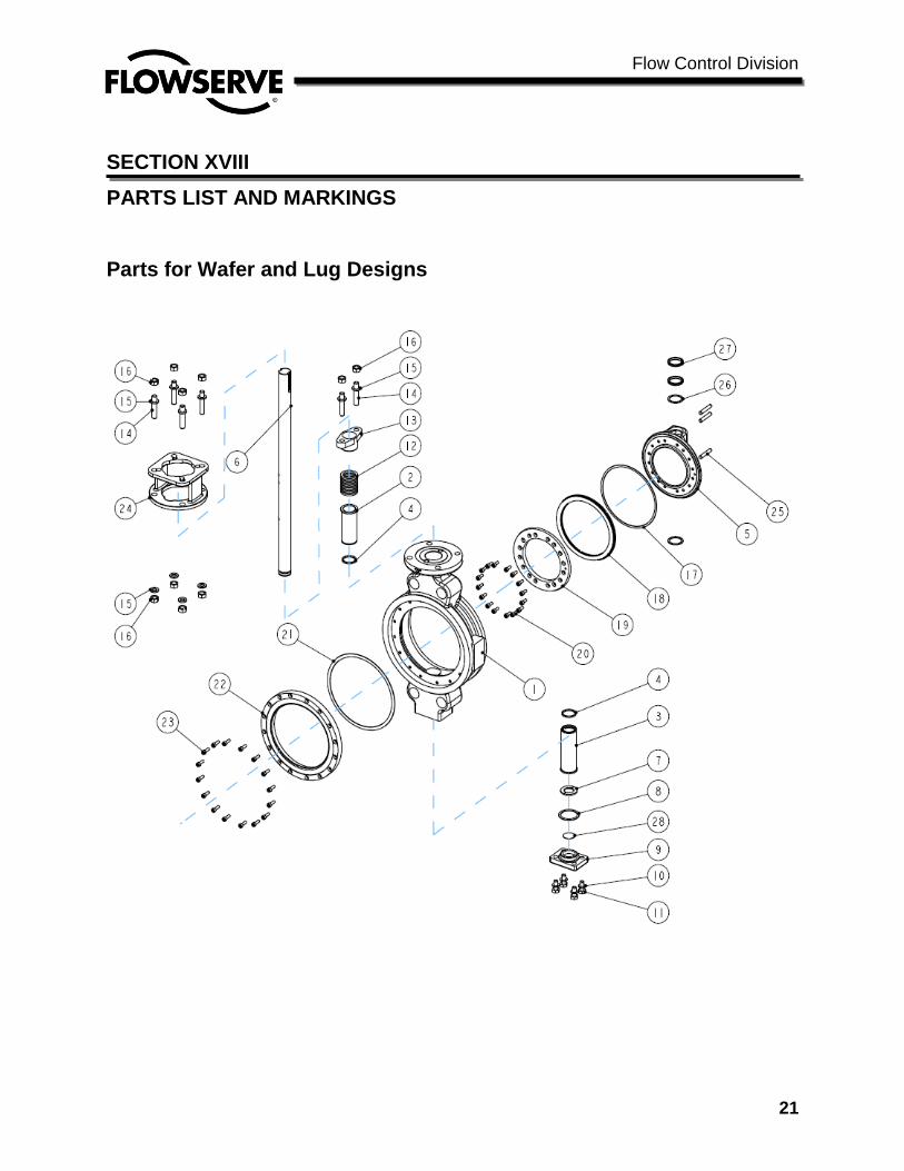
SECTION XVIII
PARTS LIST AND MARKINGS
Parts for Wafer and Lug Designs

Flow Control Division
22
Parts List for Wafer and Lug Designs
No. Name Materials Spare
parts No. Name Materials
Spare
parts
1 BODY A216 Gr. WCB
15 SPRING WASHER A240 Gr. 304
A351 Gr. CF8M 16 NUT A194 Gr. 8
2 BEARING A182 Gr. F316 17 GASKET GRAPHITE *
3 BEARING A182 Gr. F316
18
SOLID SEAL RING A240 Gr. 316
* 4 DUST-PROOF SEAL GRAPHITE INCO 718
5 DISC A216 Gr. WCB
LAMINATED SEAL RING UNS S32205
A351 Gr. CF8M INCO 718
6 SHAFT
A182 Gr. F6a
19 SEAL RING RETAINER
A351 Gr. CF8
A479 XM-19 A351 Gr. CF8M
UNS 32205 20 SOCKET HEAD CAP
BOLT A913 Gr. B8
7 THRUST RING A240 Gr. 316 21 GASKET GRAPHITE *(1)
8 BOTTOM COVER
GASKET GRAPHITE *
22 BODY SEAT
A240 Gr.
304+Stellite hard
face *(1)
9 BOTTOM COVER
A216 Gr. WCB
A240 Gr.
316+Stellite hard
face
A351 Gr. CF8M 23 SOCKET HEAD CAP
BOLT A913 Gr. B8
10 SPRING WASHER A240 Gr. 304 24 YOKE
A536 65-45-12 *(2)
11 BOLT A913 Gr. B8 A216 Gr. WCB
12 GLAND PACKING GRAPHITE * 25 PIN A182 Gr. F316
26 DUST-PROOF SEAL GRAPHITE
13 GLAND A351 Gr. CF8
27 BEARING A182 Gr. F316
A351 Gr. CF8M 28 LOCK PLATE PTFE+316SS
14 STUD A913 Gr. B8
Notes:
1. Part numbers 21, 22, 23 are only available for model Class 300 and 600 designs
Class150 valve bodies are one-piece design.
2. For part No. 24, A216 Gr. WCB is used on the following ISO 5211 sizes: F07/F05, F10/F07, 12/F10, F14/F12, F16/F14
A536 65-45-12 is used on the following sizes: F16, F25, F30, F35, F40.
3. We can supply different materials of construction to suit specific customer requirements
Flow Control Division
23
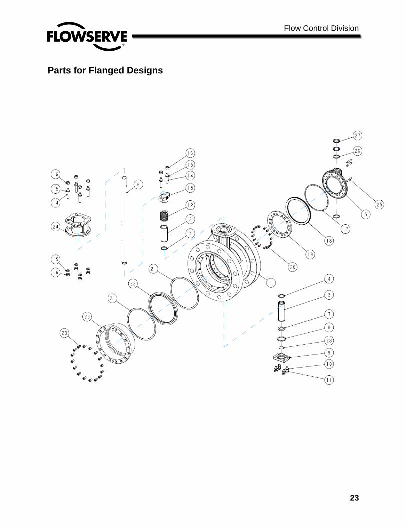
Parts for Flanged Designs
Flow Control Division
24
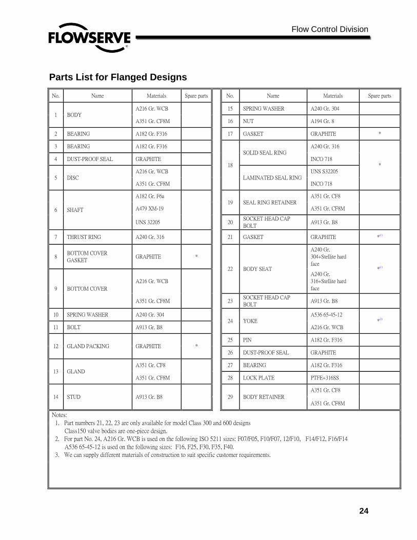
Parts List for Flanged Designs
No. Name Materials Spare parts No. Name Materials Spare parts
1 BODY A216 Gr. WCB
15 SPRING WASHER A240 Gr. 304
A351 Gr. CF8M 16 NUT A194 Gr. 8
2 BEARING A182 Gr. F316 17 GASKET GRAPHITE *
3 BEARING A182 Gr. F316
18
SOLID SEAL RING A240 Gr. 316
* 4 DUST-PROOF SEAL GRAPHITE INCO 718
5 DISC A216 Gr. WCB
LAMINATED SEAL RING UNS S32205
A351 Gr. CF8M INCO 718
6 SHAFT
A182 Gr. F6a
19 SEAL RING RETAINER
A351 Gr. CF8
A479 XM-19 A351 Gr. CF8M
UNS 32205 20 SOCKET HEAD CAP
BOLT A913 Gr. B8
7 THRUST RING A240 Gr. 316 21 GASKET GRAPHITE *(1)
8 BOTTOM COVER
GASKET GRAPHITE *
22 BODY SEAT
A240 Gr.
304+Stellite hard
face *(1)
9 BOTTOM COVER
A216 Gr. WCB
A240 Gr.
316+Stellite hard
face
A351 Gr. CF8M 23 SOCKET HEAD CAP
BOLT A913 Gr. B8
10 SPRING WASHER A240 Gr. 304 24 YOKE
A536 65-45-12 *(2)
11 BOLT A913 Gr. B8 A216 Gr. WCB
12 GLAND PACKING GRAPHITE * 25 PIN A182 Gr. F316
26 DUST-PROOF SEAL GRAPHITE
13 GLAND A351 Gr. CF8
27 BEARING A182 Gr. F316
A351 Gr. CF8M 28 LOCK PLATE PTFE+316SS
14 STUD A913 Gr. B8
29 BODY RETAINER A351 Gr. CF8
A351 Gr. CF8M
Notes:
1. Part numbers 21, 22, 23 are only available for model Class 300 and 600 designs
Class150 valve bodies are one-piece design.
2. For part No. 24, A216 Gr. WCB is used on the following ISO 5211 sizes: F07/F05, F10/F07, 12/F10, F14/F12, F16/F14
A536 65-45-12 is used on the following sizes: F16, F25, F30, F35, F40.
3. We can supply different materials of construction to suit specific customer requirements.

Flow Control Division
25
Fig.23
Each valve will be marked with an arrow to show
Recommended direction of flow
Each valve will have a casting mark as shown in Fig 24
Each valve will have the following information
in the casting as shown in Fig 25 and 26
Series Number : 870
Size: 20
Material
Heat number
Fig. 25 Fig. 26
Fig. 24
Flow Control Division
26
Printed in U.S.A. July 2010
© Flowserve Corporation
Flowserve Pte. Ltd. 12 Tuas Avenue 20 Republic of Singapore 638824 Phone 65 6879 8900
Fax 65 6862 4940