tr series - the vanjen group
TRANSCRIPT

GE Digital EnergyPower Quality
Flushmount units with display access shown
IntroductionTransient voltage surges from both external and internalsources can directly affect the performance and lifeexpectancy of electronic equipment. From electroniclighting ballasts to computer servers, if there is a printedcircuit board inside, it can be susceptible to transient voltagesurge damage. As the microprocessors and componentsthat make up this equipment grow smaller and fasterwith each new generation, their susceptibility to transientvoltage surge damage becomes ever greater.
The TR7000 SPD box extension provides the benefitsof a separate wallmounted unit, without taking upvaluable horizontal wall space. Lead lengths are kept atthe barest minimum with close-coupled box extensioninstallation. The uniform appearance of the panel withTVSS box extension available in surface and flushmountconfigurations makes the TR7000 the perfect choicefor both corridor and electrical room placement.
IDesigned for distribution but rated for service entrance,the TR7000 TVSS Box Extension has been third-partytested to ANSI/IEEE C3 (10kA 8x20μs) service entrancelevel transient surges. The entire TR7000 series line uphas been engineered to the highest standards and isdesigned for rigorous duty and long life as evidencedin our outstanding minimum repetitive surge currentcapacity test results.
The TR7000 provides maximum surge protection withoutstanding clamping characteristics for ultra high,high, medium and low exposure locations with theuse of industrial-grade MOV architecture.
TR7000 SeriesSurge Protective Device (SPD)with Enhanced Thermal Protection
Box Extensions for GE A-Series™
Branch Panelboards

DEA-435 • Page 2
Applications> Service Entrance
> Distribution Equipment
> Branch Panel
> New Construction and Retrofits
> System Expansions
Minimum Repetitive Surge Current Capacity(Per ANSI/IEEE C62.62)
The TR7000 Series is capable of surviving the followingimpulses, at one-minute intervals, without failure andwith less than 10% change in protective characteristics.
> 20,000 Category C3 impulses 20kV/10kA, 8x20μs for devices rated 125-300kA per mode(250-600kA per phase)
> 5,000 Category C3 impulses 20kV/10kA, 8x20μs for devices rated 65-100kA per mode(130-200kA per phase)
Features and Benefits> True SPD isolation is achieved on 4-wire systems
with a pull-apart hot neutral disconnect for useduring maintenance.
> The need to completely shut down power duringmaintenance has been greatly reduced because of the unique box extension design. This is ideal for panels serving critical loads such as hospitallife-safety equipment or 24/7 call center and data center servers.
> Attaches neatly to a standard panel at the top or bottom and does not create additional width or depth.
> Fast rise-times, high frequency transients and electrical line noise are reduced with standard EMI / RFI filtering technology.
> Third-party tested per IEEE C62.62 and NEMA LS-1for the rated 8x20μs surge current, per mode withfusing included.
> 10 Modes of protection (L-N, L-G, N-G, L-L)
> Green phase protection status LEDs with Red service LED
> NO/NC Form C Dry Contacts for remote monitoring
> Industrial sized MOV technology
> Thermally protected MOVs eliminate the need foradditional upstream overcurrent protection
> Audible alarm with push to test switch,Enable/Disable function
> Standard LCD surge counter
> 9 inch and 24 inch box extensions available
> Surface and flushmount-type enclosures available
> 5 year limited warranty (standard),10 year limited warranty (optional)
Standards> UL 1449 3rd Edition, Type 1 and Type 2
> UL 1283, EMI/RFI noise filter
> cUL, CSA C22.2
> ANSI/IEEE C62.41 - ANSI/IEEE C62.45
> IEEE C62.62
> NEMA LS-1 - 1992 (R2000)
> MIL-STD-220B
> ANSI/NFPA 70 (Article 285)
Technical SpecificationsNominal Discharge Current (In)20kA
Short Circuit Current Rating (SCCR)BX9 Series4 = 100kABX24 Series = 200kA
Operating Frequency50/60 Hz
Connection6 to 2/0 AWG Lugs, Parallel Connected
Operating Temp. -40° F to 149° F (-40° C to +65° C)
Operating Humidity 0% to 95% Non-Condensing
WeightBX9 Series4 = 31 lbs. (14.1 kg) BX24 Series = 57 lbs. (25.9 kg)
EnclosureNEMA 1

Page 3 • DEA-435
Phase Rating = (L-N + L-G)
NominalVoltage
(Volts RMS)
System Voltage
Configuration
120S 120/240 1 Ph, 3 W + G
120Y 120Y/208 3 Ph, 4 W + G
220Y/380 3 Ph, 4 W + G
240D 240 Delta 3 Ph, 3 W
240H 120/240 Delta HL 3 Ph, 4 W + G
240Y 240Y/415 3 Ph, 4 W + G
277Y 277Y/480 3 Ph, 4 W + G
347Y 347Y/600 3 Ph, 4 W + G
480D 480 Delta 3 Ph, 3 W
B XR 7
220Y
Maximum Surge Current Capacity
Per Mode Per Phase Suffix Description Mounting ThroughPanel Display
65kA 130kA
80kA 160kA
100kA 200kA
125kA 250kA
150kA 300kA
06
08
10
12
15
200kA 400kA20
250kA 500kA25
300kA 600kA30
MCOVMax. Continuous
Operating Voltage
L-N/G (Vrms)
For details, please contact GE Power QualityCustomer Service at 800 637 1738.
Catalog # example: TPR7120S06BX9S– 120/240 V, 1 Ph, 3 W + G– 65kA per mode, 130kA per phase– 9" Surfacemount, No Display
Voltage Code 120S / 120Y 240D 240H 220Y / 240Y / 277Y 347Y 480D
Protection Mode L-N L-G N-G L-L L-G L-L L-N HL-N L-G HL-G N-G L-L HL-L L-N L-G N-G L-L L-N L-G N-G L-L L-G L-L
UL 1449, 3rd Edition Voltage Protection Ratings (VPR)(assigned UL rating)
1500 1500 900 1800 1800 2500 1500 1800 1500 2000 900 1800 3500 1800 2000 1500 2500 2000 2000 1800 3000 2500 4000
UL 1449, 2nd Edition Suppression Voltage Ratings (SVR)(assigned UL rating) *
500 500 500 700 700 1500 500 700 500 700 500 900 — 800 800 800 1500 1200 1000 1000 2000 1500 3000
B X 9 Protection Ratings
* NOTE: SVR Ratings are no longer assigned by UL and are included in the table above for reference purposes only.
Voltage Code 120S / 120Y 240D 240H 220Y / 240Y / 277Y 347Y 480D
Protection Mode L-N L-G N-G L-L L-G L-L L-N HL-N L-G HL-G N-G L-L HL-L L-N L-G N-G L-L L-N L-G N-G L-L L-G L-L
UL 1449, 3rd Edition Voltage Protection Ratings (VPR)(assigned UL rating)
1500 1500 1000 1800 1800 2500 1500 1800 1500 1800 1000 1800 3300 1800 1800 1500 2500 3000 2500 1800 3000 2500 4000
UL 1449, 2nd Edition Suppression Voltage Ratings (SVR)(assigned UL rating) *
400 400 400 700 700 1500 500 700 400 700 400 900 — 800 800 800 1500 1200 1000 1000 2000 1500 3000
B X 2 4 Protection Ratings
A
B
B
C,D
E
B
B
SourceConfig-uration
B
C,D
9" Panel Box Ext, Type 1 Surface No
9" Panel Box Ext, Type 1 Surface Yes
9" Panel Box Ext, Type 1 Flush No
9" Panel Box Ext, Type 1 Flush Yes
24" Panel Box Ext, Type 1 Surface Yes
24" Panel Box Ext, Type 1 Flush Yes
9ST1
9WST1
9FT1
9WFT1
24WST1
24WFT1
UL TYPE 1
Suffix Description Mounting ThroughPanel Display
UL TYPE 2
9" Panel Box Ext, Type 2 Surface No
9" Panel Box Ext, Type 2 Surface Yes
9" Panel Box Ext, Type 2 Flush No
9" Panel Box Ext, Type 2 Flush Yes
24" Panel Box Ext, Type 2 Surface Yes
24" Panel Box Ext, Type 2 Flush Yes
9S
9WS
9F
9WF
24WS
24WF
*
*
*
*L1
N
L2
L1
N
L3L2
L1
L3L2
L1
L3L2
L1
L3L2
N
A B C D E
Source Configuration Diagrams
150
150
320
270
150/270 HL
320
320
420
550

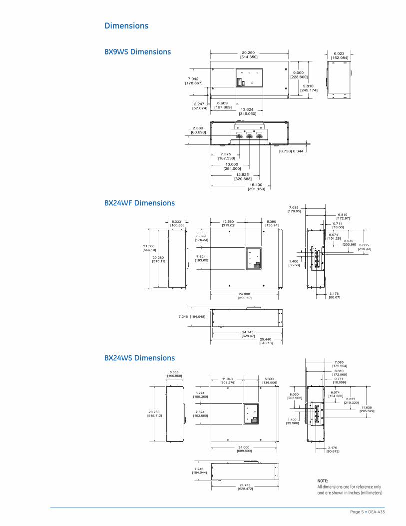
NOTE:All dimensions are for reference onlyand are shown in Inches [millimeters]
DEA-435 • Page 4
Dimensions
BX9S Dimensions
9.000 [228.6]
9.810 [249.174]
20.250 [514.35]
7.375 [187.338]
10.000 [254]
12.6255 [320.69]
15.400 [391.16]
1.719 [43.675]
0.344 [8.738]
6.023 [152.984]
0.042 [1.067]
BX9WF Dimensions
10.440 [265.176]
9.000 [228.600]
21.500 [546.100]
1.617 [41.072]
6.412 [162.865]
7.239 [183.871]
14.254 [362.052]
7.375 [187.338]
10.000 [254.000]
12.625 [320.688]
15.400 [391.160]
6.023 [152.984]
0.588 [14.935]
2.389 [60.693]
0.344 [8.738]
BX9F Dimensions 21.500 [546.10]
10.440 [265.18]
9.000 [228.60]
7.375 [187.34]
10.000 [254.00]
12.625 [320.69]
1.719 [43.67]
0.344 [8.74]
6.023 [152.98]
0.588 [14.94]
NOTE:All dimensions are for reference onlyand are shown in Inches [millimeters]
Page 5 • DEA-435
BX24WF Dimensions
6.333 [160.86]
20.280 [515.11]
21.500 [546.10]
24.743 [628.47]
25.440 [646.18]
24.000 [609.60]
12.560 [319.02]
5.390 [136.91]
6.899 [175.23]
7.624 [193.65]
6.810 [172.97]
7.085 [179.95]
3.176 [80.67]
0.711 [18.06]
6.074 [154.28]
8.030 [203.96] 8.635
[219.33]
1.400 [35.56]
7.246 [184.048]
BX24WS Dimensions
24.743 [628.472]
7.246 [184.044]
20.280 [515.112]
6.333 [160.858]
24.000 [609.600]
11.940 [303.276]
5.390 [136.906]
6.274 [159.360]
7.624 [193.650]
6.810 [172.969]
7.085 [179.954]
8.635 [219.329]
11.635 [295.529]
8.030 [203.962]
1.400 [35.560]
3.176 [80.672]
0.711 [18.059]
6.074 [154.280]
BX9WS Dimensions 20.250 [514.350]
9.810 [249.174]
9.000 [228.600]
2.247 [57.074]
7.042 [178.867]
6.609 [167.869] 13.624
[346.050]
6.023 [152.984]
2.389 [60.693]
7.375 [187.338]
10.000 [254.000]
12.625 [320.688]
15.400 [391.160]
[8.738] 0.344
Dimensions
DEA-435 (3/10)
GE Digital Energy – Power Quality830 W 40th Street, Chicago, IL 60609 USA800 637 1738 www.gepowerquality.com
Information subject to change without notice. Please verify all details with GE. © 2010 General Electric Company All Rights Reserved
Contact UsDigital Energy…we protect and connect the world’s criticalequipment to ensure safe, reliable power