indirect fired water heaters tr series smart series · indirect fired water heaters tr series...
TRANSCRIPT

Indirect Fired Water HeatersTR Series
Technical SpecificationsInstallation and Maintenance Guide
WARNING• Before proceeding with installation and operation, read entire manual care-
fully. Failure to do so can cause injury or property damage.
• When receiving Phase III® equipment, any claims for damage or short-age in shipment must be filed immediately against the transportationcompany by the consignee.
2004-1 PIII Ind. Manual 1/04
IMPORTANT
• Warranty Registration Card must be filled out by the customer and mailedwithin thirty (30) days of installation in order to gain warranty coverage.
• Retain and affix this manual near the water heater for future reference
• Installation and service should only be performed by a qualified installer orservice technician.
• Installations and service should be performed by a license plumber or gasfitter in the Commonwealth of Massachusetts.
SMART Series
US & Canada

Phase III®
Product & Safety Information . . . . . . . . . . . . . . . . . . . . . . . . . . . . . . . .1
Pre-Installation . . . . . . . . . . . . . . . . . . . . . . . . . . . . . . . . . . . . . . . . . . . .2-3
Installation - Piping- Temperature & Pressure (T&P) Relief Valve . . . . . . . . . . . . . . . .4-5- Drain Valve . . . . . . . . . . . . . . . . . . . . . . . . . . . . . . . . . . . . . . . . .5- Automatic Air Vent . . . . . . . . . . . . . . . . . . . . . . . . . . . . . . . . . . .5- Thermal Expansion . . . . . . . . . . . . . . . . . . . . . . . . . . . . . . . . . .5- Water Hammer . . . . . . . . . . . . . . . . . . . . . . . . . . . . . . . . . . . . . .6- Vacuum Breaker . . . . . . . . . . . . . . . . . . . . . . . . . . . . . . . . . . . . .6- General Piping . . . . . . . . . . . . . . . . . . . . . . . . . . . . . . . . . . . . . .6- Domestic Piping . . . . . . . . . . . . . . . . . . . . . . . . . . . . . . . . . . . . .6-7- Thermostatic Mixing Valve . . . . . . . . . . . . . . . . . . . . . . . . . . . . .7- Recirculation Piping . . . . . . . . . . . . . . . . . . . . . . . . . . . . . . . . . .7- Multiple Water Heater Systems . . . . . . . . . . . . . . . . . . . . . . . . .7- Boiler Piping . . . . . . . . . . . . . . . . . . . . . . . . . . . . . . . . . . . . . . . .7
Installation -Piping Drawings . . . . . . . . . . . . . . . . . . . . . . . . . . . . . . . . .8-14
Installation - Wiring- Wiring Requirements . . . . . . . . . . . . . . . . . . . . . . . . . . . . . . . . . .15- Circulators . . . . . . . . . . . . . . . . . . . . . . . . . . . . . . . . . . . . . . . . .15- Zone Valves . . . . . . . . . . . . . . . . . . . . . . . . . . . . . . . . . . . . . . . .15- Snap-Set Connection . . . . . . . . . . . . . . . . . . . . . . . . . . . . . . . . . .15
Installation - Wiring Drawings . . . . . . . . . . . . . . . . . . . . . . . . . . . . . . . .16-19
Water Heater Start-Up- Filling the Inner (Domestic Water) Tank . . . . . . . . . . . . . . . . . . .20- Filling the Outer (Boiler Water) Tank . . . . . . . . . . . . . . . . . . . . .20- General Notes . . . . . . . . . . . . . . . . . . . . . . . . . . . . . . . . . . . . . . .21- Adjusting the Water Heater Thermostat . . . . . . . . . . . . . . . . . . . .22
Water Heater Maintenance- Maintenance Schedule . . . . . . . . . . . . . . . . . . . . . . . . . . . . . . . . .23- Filling Water Heater . . . . . . . . . . . . . . . . . . . . . . . . . . . . . . . . . .23- Draining Water Heater . . . . . . . . . . . . . . . . . . . . . . . . . . . . . . . . .23-24- Draining Inner (Domestic Water) Tank . . . . . . . . . . . . . . . . . . . .24- Draining Outer (Boiler Water) Tank . . . . . . . . . . . . . . . . . . . . . .24
Tables of Contents
Page

Water Heater Specifications- TR Series . . . . . . . . . . . . . . . . . . . . . . . . . . . . . . . . . . . . . . . . . .25- SMART Series . . . . . . . . . . . . . . . . . . . . . . . . . . . . . . . . . . . . . .26
Performance . . . . . . . . . . . . . . . . . . . . . . . . . . . . . . . . . . . . . . . . . . . . . .27
Replacement Parts List- TR Series . . . . . . . . . . . . . . . . . . . . . . . . . . . . . . . . . . . . . . . . . .28- SMART Series . . . . . . . . . . . . . . . . . . . . . . . . . . . . . . . . . . . . . .28
Sample Specifications . . . . . . . . . . . . . . . . . . . . . . . . . . . . . . . . . . . . . . .29
Warranty (See Warranty Certificate enclosed in your water heater package)
Phase III® Tables of Contents
Page

Phase III®
1
Product & Safety Information
Following terms are used to bring attention to thepresence of various risk levels, or to importantinformation concerning product life.
Indicates presence of a hazard which willcause severe personal injury, death or sub-stantial property damage if ignored.
Indicates the presence of a hazard whichcan cause severe personal injury, death orsubstantial property damage if ignored.
Indicates the presence of a hazard whichwill or can cause minor personal injury ordamage if ignored.
Indicates special instructions on installa-tion, operation, or maintenance which areimportant but not related to personal injuryhazards.
Hot Water Can Scald!
• Water temperatures over 125ºF can causesevere burns instantly or death from scalding.
• Children, disabled and elderly are at highestrisk of being scalded.
• Never leave them unattended in or near shower,bathtub or sink.
• Never allow small children to use a hot waterfaucet or draw their own bath.
• If anyone using hot water in the building fitsthis description or if local codes or state lawsrequire specific water temperatures at hotwater faucet, it is recommended:
- to install a thermostatic mixing valve at thisappliance or at each water faucet.or
- to set the thermostat knob for the lowest tem-perature which satisfies your hot waterneeds.
• Water drained from the system drain valvesmay be extremely hot. To avoid injury:
– Make sure all connections are tight.– Direct water flow away from any person.
Protection must be taken against excessivetemperature and pressure!
• Installation of a Temperature & Pressure(T&P) relief valve is required.
To prevent damage to the inner tank, theInstaller must:
• Always fill inner tank prior to outer tankand always drain outer tank prior to innertank.
• Relieve primary system pressure below 15psig prior to draining inner tank.
CAUTION
CAUTION
DANGER
NOTICE
CAUTION
WARNING
DANGER
Phase III®
2
Pre-Installation
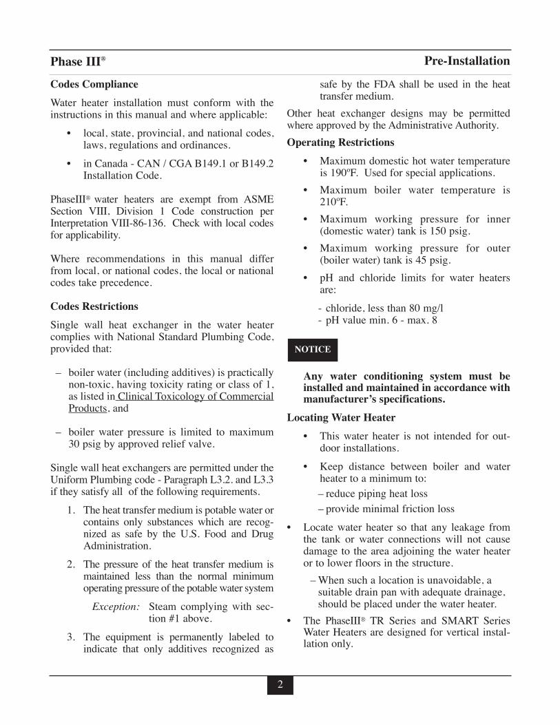
Codes Compliance
Water heater installation must conform with theinstructions in this manual and where applicable:
• local, state, provincial, and national codes,laws, regulations and ordinances.
• in Canada - CAN / CGA B149.1 or B149.2Installation Code.
PhaseIII® water heaters are exempt from ASMESection VIII, Division 1 Code construction perInterpretation VIII-86-136. Check with local codesfor applicability.
Where recommendations in this manual differfrom local, or national codes, the local or nationalcodes take precedence.
Codes Restrictions
Single wall heat exchanger in the water heatercomplies with National Standard Plumbing Code,provided that:
– boiler water (including additives) is practicallynon-toxic, having toxicity rating or class of 1,as listed in Clinical Toxicology of CommercialProducts, and
– boiler water pressure is limited to maximum30 psig by approved relief valve.
Single wall heat exchangers are permitted under theUniform Plumbing code - Paragraph L3.2. and L3.3if they satisfy all of the following requirements.
1. The heat transfer medium is potable water orcontains only substances which are recog-nized as safe by the U.S. Food and DrugAdministration.
2. The pressure of the heat transfer medium ismaintained less than the normal minimumoperating pressure of the potable water system
Exception: Steam complying with sec-tion #1 above.
3. The equipment is permanently labeled toindicate that only additives recognized as
safe by the FDA shall be used in the heattransfer medium.
Other heat exchanger designs may be permittedwhere approved by the Administrative Authority.
Operating Restrictions
• Maximum domestic hot water temperatureis 190ºF. Used for special applications.
• Maximum boiler water temperature is210ºF.
• Maximum working pressure for inner(domestic water) tank is 150 psig.
• Maximum working pressure for outer(boiler water) tank is 45 psig.
• pH and chloride limits for water heatersare:
- chloride, less than 80 mg/l- pH value min. 6 - max. 8
Any water conditioning system must beinstalled and maintained in accordance withmanufacturer’s specifications.
Locating Water Heater
• This water heater is not intended for out-door installations.
• Keep distance between boiler and waterheater to a minimum to:– reduce piping heat loss– provide minimal friction loss
• Locate water heater so that any leakage fromthe tank or water connections will not causedamage to the area adjoining the water heateror to lower floors in the structure.
– When such a location is unavoidable, asuitable drain pan with adequate drainage,should be placed under the water heater.
• The PhaseIII® TR Series and SMART SeriesWater Heaters are designed for vertical instal-lation only.
NOTICE

3
Phase III® Pre-Installation
Recommended Clearances
• Water heater should be installed to allowadequate clearance for servicing
• Zero clearance is permissible to either sideof the TR and SMART Series water heater,but information labels may be hidden.
• Recommended top or vertical clearance is 12”minimum.
• Refer to boiler manual for boiler clearances
Water�Heater
Wall
TR Tank- Top View
12" Minimum
Water�Heater
Wall 12" Minimum
SMART Tank- Top View

Phase III®
4
Installation
Temperature & Pressure (T&P) Relief Valve
To reduce risk of excessive pressures and tem-peratures in the water heater, install tempera-ture and pressure protective equipmentrequired by local codes, but no less than a com-bination temperature and pressure relief valvecertified by a nationally recognized testing lab-oratory that maintains periodic inspection ofproduction of listed equipment or materials, asmeeting the requirements for Relief Valves andAutomatic Gas Shutoff Devices for Hot WaterSupply Systems, ANSI Z21.22. This valve mustbe marked with a maximum working pressureof the water heater.
• Every Phase III® water heater must be protect-ed with a T&P relief valve.
• Determine T&P relief valve size by the follow-ing specifications, unless they conflict withlocal codes:
- TR 20/30/36/45 - SMART 20/30/40/50:3/4”NPT with an AGA Rating of 100,000BTU/hr. (Watts 100XL-8 or equivalent).
- TR 60/80/100/120 - SMART 60/80/100:3/4”NPT with an AGA Rating of 200,000BTU/hr. (Watts 40XL-8 or equivalent).
For proper operation of the T&P and to pre-vent the T&P from activating due to boilerwater temperature, use a T&P relief valvewith extended element. Recommended, an8” minimum length.
Phase III® commercial water heaters willabsorb less than 200,000 BTU/hr whendomestic water outlet temperature is 210ºFand boiler water supply temperature is240ºF. Listed outputs are based on ASMESection VIII Interpretation VIII-1-86-136.Check with local codes for applicability.
Standard Installation
• Install T&P relief valve in the Auxiliary con-nection located behind the air vent on the top ofthe water heater (Figure 1 page 8).
or
• Install the T&P relief valve in the run (straightthrough leg) of a tee located at the domestic hotwater outlet when using the Auxiliary connec-tion for a recirculation return (Figure 2 page 9).
Commonwealth of Massachusetts Installation
Follow this procedure for jurisdictions requiring avacuum breaker to be installed on the domesticcold water inlet.
• Install the T&P in the run (straight through leg)of a tee located at the domestic hot water out-let. Use a long element T&P relief valve(Figure 3 page 10).
NOTICE
NOTICE
CAUTION

Phase III®
5
Installation
T&P Relief Valve Discharge Piping
T&P relief valve discharge piping must be:
- made of material serviceable for tempera-tures of 250ºF or greater.
- directed so that hot water flows away fromall persons.
- directed to a suitable place for disposal.
- installed so as to allow complete drainingof the T&P relief valve and discharge line.
T&P relief valve discharge piping must not be:
- excessively long. Using more than 2elbows or 15 feet of piping can reduce dis-charge capacity.
- directly connected to a drain. Terminatedischarge piping within 6” from drain.Refer to local codes.
- plugged, reduced or restricted.
- subject to freezing.
Do not install any valve between T&P reliefvalve and tank connection or on T&P reliefvalve discharge piping. Do not plug T&Prelief valve or discharge piping. Improperplacement and piping of T&P relief valvecan cause severe personal injury, death orsubstantial property damage.
Drain Valve
Drain valve and fittings are supplied by others.
Standard Installation
• Install a tee connection at the domestic coldwater inlet (Figures 1 and 2 pages 8 and 9).
• Pipe the drain piping with drain valve from thetee connection to:- a suitable place for disposalor- terminate within 12” of the floor
Commonwealth of Massachusetts Installation
• Insert an open-end dip tube into the Auxiliaryconnection on top of water heater.
• Install a 3/4” NPT elbow to the Auxiliary con-nection (Figure 3).
• Pipe the drain piping with drain valve from theelbow connection to:- a suitable place for disposalor- terminate within 12” of the floor
Automatic Air Vent
1. Remove plastic shipping cap from 1/2” NPTpipe fitting on top center of water heater.
2. Install 1/2” x 1/8” reducer bushing provided withwater heater, using suitable pipe dope or tape.
3. Install automatic air vent provided with waterheater, using suitable pipe dope or tape.
4. Unscrew vent cap on air vent one full turn. Leavecap unscrewed one turn for normal venting.
Thermal Expansion
If a backflow preventer, check valve or pressurereducing valve is piped on cold water supply pipingof water heater, install an expansion tank on coldwater supply line to prevent normal thermal expan-sion from repeatedly forcing open T&P relief valve.
T&P relief valve is not intended for constantduty, such as relief of pressure due torepeated normal system expansion. Correctthis condition by installing a properly sizedexpansion tank in domestic water system.Refer to expansion tank manufacturer’sinstallation instructions for proper sizing.
CAUTION
WARNING

Phase III®
6
Installation
Water Hammer
Dishwashers, clothes washers and fast-closing pos-itive shut-off valves incorporated in the system allcontribute to creating water shock. Install a waterhammer arrester to prevent damage to pipes andappliances. See device manufacturer’s instructionsfor application and installation.
Water hammering within the domestic pip-ing system can cause premature failure ofthe inner tank of the water heater. This typeof failure is NOT covered under warranty.
Vacuum Breaker
Installing a vacuum breaker on the domestic coldwater outlet will prevent damage to the inner tankif a negative pressure is developed in the domesticsupply line. See manufacturer’s instructions forapplication and installation of the vacuum breaker.
General Piping
• For domestic water piping diagrams, see page 8thru 10.
• See pages 11 through 14 for:
- Boiler water piping
- Multiple water heater domestic and boilerpiping.
• See Chart 1 for domestic and boiler pipingconnections.
• All plumbing must meet or exceed all local,state and national plumbing codes.
• Use pipe dope or tape suitable for potablewater systems.
• Use isolation valves to isolate system components.
Domestic Piping
• Union on domestic hot water outlet should bepiped at a higher elevation than domestic waterdrain valve. This will make draining the waterheater easier.
• Install unions for easy removal of water heater.Use dielectric unions or couplings to protect
NOTICE
Chart 1
Connections - NPT Recirculation Dip Tube Draining Dip Tube RecommendedWater Heater Domestic Boiler Water Auxiliary Length Diameter Length Diameter Minimum
Model Water Supply/ Connection inches inches inches inches Boiler PipingInlet/Outlet Return Diameter (inches)
TR-20 3/4 1 3/4 34 3/4 34 3/4 1TR-30 3/4 1 3/4 43 3/4 43 3/4 1TR-36 3/4 1 3/4 52 3/4 52 3/4 1TR-45 1 1 1/4 3/4 25 3/4 47 3/4 1 1/4TR-60 1 1 1/4 1 25 1 54 1 1 1/4TR-80 1 1/2 2 1 1/2 25 1 1/2 48 1 1/2 2TR-100 1 1/2 2 1 1/2 32 1 1/2 61 1 1/2 2TR-120 1 1/2 2 1 1/2 32 1 1/2 61 1 1/2 2
SMART 20 3/4 1 3/4 23.5 3/4 23.5 3/4 1SMART 30 3/4 1 3/4 34 3/4 34 3/4 1SMART 40 3/4 1 3/4 43 3/4 43 3/4 1SMART 50 3/4 1 1/4 3/4 25 3/4 52 3/4 1 1/4SMART 60 3/4 1 1/4 3/4 34 3/4 62 3/4 1 1/4SMART 80 1 1/2 1 1/2 1 1/2 25 1 1/2 48 1 1/2 1 1/2SMART 100 1 1/2 1 1/2 1 1/2 32 1 1/2 61 1 1/2 1 1/2

Phase III®
hot and cold water fittings from corrosionwhen connecting dissimilar materials such ascopper and galvanized iron pipe.
• If copper pipe is used for domestic water con-nections, first solder pipe to a threaded adapterand then screw adapter into cold water inlet ontop of water heater. Inlet contains an internalplastic dip tube which can be damaged by heatfrom soldering.
Do not apply heat to the cold water inletwhen making sweat connections to waterheater. Sweat tubing to adapter before fit-ting adapter to cold water inlet of heater. Itis imperative that no heat be applied to thecold water inlet, as it contains a non metal-lic dip tube.
• When the water supply pressure is higher than70 psig, it is recommended to install a pressurereducing valve on cold water supply line toprevent water loss through T&P relief valve.
• If water heater will replace tankless coil inboiler, disconnect piping to coil. Allow waterto drain from coil. Do not plug tankless coil.
Plugging tankless coil inlet and outlet willresult in severe personal injury, death, orsubstantial property damage.
Thermostatic Mixing Valve
• Optional mixing valve may be installed on thedomestic hot water outlet.
• Mixing valve should comply with ASSE 1017
Recirculation Piping
• T&P relief valve must be installed in run(straight through leg) of tee located at domestichot water outlet of water heater.
• Recirculation dip tube must be installed in aux-iliary connection. See Chart 1 page 6 for sizing.
• A stainless steel or bronze circulator is recom-mended
• Install automatic mixing valve either at the hotwater outlet of water heater or each hot waterfaucet.
Multiple Water Heater Systems - RecirculationPiping
• Parallel Pipe recirculation Systems - Manifoldrecirculation return to all water heaters.
• Series Piped Systems - Piped return to the lead-ing (cold water inlet) water heater.
• Install automatic mixing valve either at the hotwater outlet of water heater or each hot waterfaucet.
Failure to install automatic mixing valvewhere recommended will result in severepersonal injury or death.
Boiler Piping
• If plastic pipe is used for boiler water piping, itmust have a maximum oxygen diffusion rate of0.1 mg/liter-day for boiler and water heaterprotection.
• Boiler water (including additives) must bepractically non-toxic, having toxicity rating orclass of 1, as listed in Clinical Toxicology ofCommercial Products.
If antifreeze is used in boiler system, localcodes may require a backflow preventer oncold water supply line. Use antifreeze specifi-cally intended for hydronic heating systems.Inhibited propylene glycol is recommended ata maximum 50/50 mixture.
Do not use automotive, ethylene glycol orpetroleum-based antifreeze. Do not use anyundiluted antifreeze. This can cause severepersonal injury, death or substantial propertydamage.
DANGER
DANGER
DANGER
NOTICE
7
Installation

Phase III®
8
Installation - Piping
Cold Water Inlet6 1
12" min.Heat Trap
Loop
12" min.Heat Trap
Loop
1 5
5 1
10
9
4
13M H
C
Cold Water Inlet6 1
12" min.Heat Trap
Loop
12" min.Heat Trap
Loop
4
1 5
5 1
10
13
9
M H
C
Standard InstallationDomestic PipingTR Series
1. Shut-off valve4. T&P relief valve5. Unions6. Backflow preventer or pressure reducing valve(*)
9. Drain valve10. Thermal expansion tank (potable)13. Thermostatic mixing valve (optional)
(*) Optional devices may be required by local codes.
Standard InstallationDomestic PipingSMART Series
Figure 1
Phase III®
9
Cold Water Inlet
6 1
RecirculatingLoop
2 3
4
1 5
5 1
10
9
12" min.Heat Trap
Loop
12" min.Heat Trap
Loop
11
Cold Water Inlet6 1
RecirculatingLoop
2
11
3
12" min.Heat Trap
Loop
12" min.Heat Trap
Loop
4
1 5
5 1
10
9
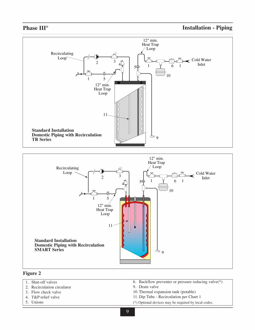
Standard InstallationDomestic Piping with RecirculationTR Series
1. Shut-off valves2. Recirculation circulator3. Flow check valve4. T&P relief valve5. Unions
6. Backflow preventer or pressure reducing valve(*)9. Drain valve10. Thermal expansion tank (potable)11. Dip Tube - Recirculation per Chart 1(*) Optional devices may be required by local codes.
Standard InstallationDomestic Piping with RecirculationSMART Series
Figure 2
Installation - Piping

Phase III®
10
Cold Water Inlet6 1
12" min.Heat Trap
Loop
12" min.Heat Trap
Loop
4
1 5
5
10
9
8
11
13M H
C
Cold Water Inlet6 1
11
12" min.Heat Trap
Loop
12" min.Heat Trap
Loop
4
1 5
5
10
9
813M H
C
Commonwealth of MassachusettsDomestic PipingTR Series
1. Shut-off valves4. T&P relief valve5. Unions6. Backflow preventer or pressure reducing valve8. Vacuum breaker
9. Drain valve10. Thermal expansion tank (potable)11. Dip tube - Draining per Chart 113. Mixing valve (optional)
Figure 3
Commonwealth of MassachusettsDomestic PipingSMART Series
Installation - Piping

Phase III®
11
91
7
2
2-PortPriority Valve
(normally open)
2-PortPriority Valve
(normally close)
1
12
11
Cold waterinlet
SMART Series
1
2
9
1
3- PortPriorityValve
71
12
Cold waterinlet
11
SMART Series
Installation - Piping
Fig. 5:
1. Shut-off valves2. Circulator7. Expansion tank
9. Drain valve11. Feed valve12. Air separator
Fig. 4: Phase III® System Piping with 3-Port Zone Valve(Domestic Priority)
Phase III® System Piping with 2-Port Zone Valves(Domestic Priority)
TR Series
TR Series
Note: See page 25 for TR Series BoilerSupply and Return Connections.
Note: See page 25 for TR Series BoilerSupply and Return Connections.

Phase III®
12
91
1
2
Zonevalve
Zone Valve
17
12
11
Cold waterinlet
SMART Series
91
1 3
2
22
ZoneCirculator
Zone Circulator
7 1
12
11
Cold waterinlet
SMART Series
Fig. 7:
Installation - Piping
Fig. 6:
1. Shut-off valves2. Circulator3. Flow check valve7. Expansion tank
9. Drain valve 11. Feed valve12. Air separator
Phase III® System Piping with Zone Valves(Non Domestic Priority)
Phase III® System Piping with Zone Circulators
TR Series
TR Series
Note: See page 25 for TR Series BoilerSupply and Return Connections.
Note: See page 25 for TR Series BoilerSupply and Return Connections.

Phase III®
• Recommended for applications in which there is alarge water consumption in short period of time.
• Amaximum of 3 water heaters may be piped in series.
• Utilize the lead (hot water outlet) Phase III® tank ther-mostat to control system temperature.
• Install automatic mixing valve at either the hot wateroutlet of the water heater system or at each hot waterfixture.
• Each tank should be piped with a drain as shown inFig. 1.
13
Installation - Piping
Circulator
RecirculatedWater
AutomaticMixing Valve
Hot WaterOutlet Cold Water
Inlet
T&PReliefValve Cold Water
Inlet
IsolationValve
Circulator
AutomaticMixing Valve
Hot WaterOutlet
Cold WaterInlet
T&PReliefValve
Cold WaterInlet
IsolationValve
RecirculatedWater
Multiple TR Series Water Heater SystemDomestic Piping - Parallel
Multiple TR Series Water Heater SystemDomestic Piping - Series
• Recommended for most applications.• Any one water heater tank thermostat may be uti-
lized to control system temperature.• Install automatic mixing valve at either the hot
water outlet of the water heater system or at eachhot water fixture.
• Each tank should be piped with a drain as shown inFig. 1.
Fig. 8:
Fig. 9:

Phase III®
14
1
23
9
7 1
12
Cold waterinlet
11
1
2
3
9
71
12
Cold waterinlet
11
Installation - Piping
1. Shut-off valves2. Circulator3. Flow check valve7. Expansion tank
9. Drain valve11. Feed valve12. Air separator
Fig. 10: Multiple TR Series Water Heater System Boiler PipingReverse Return Balanced Flow
Multiple TR Series Water Heater System Boiler Piping - ManifoldFig. 11:

15
Phase III®
Wiring Requirements
Electrical shock hazard can cause severepersonal injury, death or substantial prop-erty damage. Disconnect power beforeinstalling and/or servicing.
1. All wiring must be a minimum of 18 gaugeand installed in accordance with:
• U.S.A. - National Electrical Code and anyother national, state or local code require-ments having jurisdiction.
• Canada - C.S.A. C22.1 Canadian ElectricalCode Part 1 and any other national, provin-cial and local code requirements havingjurisdiction.
2. If original wire supplied with appliance mustbe replaced, Type 90ºC or its equivalent mustbe used.
3. Refer to control component instructionspacked with boiler for application information.
4. An optional service switch may be installed inwater heater electrical circuit. This switchwould only shut off the water heater, not thehome heating system. Do not shut off waterheater if there is a chance of freezing.
5. All electrical contacts shown do not havepower applied - off the shelf condition. Seepages 16 thru 19.
Circulators
• Priority relay must be sized for total amp drawof all circulators.
Zone Valves
• Transformer must be sized for maximum loadof all zone valves.
Snap Set Connection
• For easy wiring between water thermostat andboiler controls see Installation Wiring sectionpages 16 through 19.
• Make sure snap set is firmly snapped togetherafter wiring.
WARNING
Snap Set Wiring
Connect to �outer 2 terminals
Installation

Phase III®
16
H H
High Voltage
120V.A.C.
24V.A.C.
RoomThermostat
Zone 1
Additional zones Additional zones maybe added as shown above
Transformer(Power)
Zone Valve
Zone Valve
12C
Water HeaterThermostatSnap-Set
WaterHeaterZone
*Isolation Relay
BoilerThermostatTerminals
* Use isolation relay on3-wire zone valves withnon-isolated end switches.Transformer and boilercontrol can burn out if isolation relay is not used
PriorityRelay
H H
High Voltage
120V.A.C.
24V.A.C.
RoomThermostat
Zone 1
Additional zones Additional zones maybe added as shown above
Transformer(Power)
Zone Valve
Zone Valve
12C
Water HeaterThermostatSnap-Set
WaterHeaterZone
BoilerThermostatTerminals
High VoltageLow VoltageBoiler Low Voltage
PriorityRelay
Typical 3-wire Zone Valve Zoning,with Domestic Priority
Installation - Wiring
Typical 4-wire Zone Valve Zoning,with Domestic Priority
Fig. 12: Fig. 13:

Phase III®
H H
High Voltage
120V.A.C.
24V.A.C.
RoomThermostat
RoomThermostat
Zone 1
Zone 2
Additional zones Additional zones maybe added as shown above
Transformer(Power)
Zone Valve
Zone Valve
Zone Valve
12C
Water HeaterThermostatSnap-Set
WaterHeaterZone
*Isolation Relay
BoilerThermostatTerminals
* Use isolation relay on3-wire zone valves withnon-isolated end switches.Transformer and boilercontrol can burn out if isolation relay is not used
17
Typical 3-wire Zone Valve Zoning,without Domestic Priority
Installation - Wiring
H H
High Voltage
120V.A.C.
24V.A.C.
RoomThermostat
RoomThermostat
Zone 1
Zone 2
Additional zones Additional zones maybe added as shown above
Transformer(Power)
Zone Valve
Zone Valve
Zone Valve
12C
Water HeaterThermostatSnap-Set
WaterHeaterZone
BoilerThermostatTerminals
High VoltageLow VoltageBoiler Low Voltage
Typical 4-wire Zone Valve Zoning,without Domestic Priority
Fig. 14: Fig. 15:

Phase III®
2
T T
1 4 3 5 6
CirculatorZone 1
Thermostatzone 1Honeywell
R845ARelay
120H
VACN
2
T T
1 4 3 6
CirculatorZone 2
Thermostatzone 2
5
2
T T
1 4 3 6
WaterHeater
Circulator
Water HeaterThermostatSnap-Set
5
12
C
BoilerThermostatTerminals
Priority Relay
18
Typical Circulator Zoningwith Domestic Priority
Installation - Wiring
2
T T
1 4 3 5 6
CirculatorZone 1
Thermostatzone 1Honeywell
R845ARelay
120H
VACN
2
T T
1 4 3 6
CirculatorZone 2
Thermostatzone 2
5
2
T T
1 4 3 6
WaterHeater
Circulator
Water HeaterThermostatSnap-Set
5
12
C
High VoltageLow Voltage
BoilerThermostatTerminals
Typical Circulator Zoningwithout Domestic Priority
Fig. 16: Fig. 17:

Phase III®
19
Installation - Wiring
T T
1 4 3 5 6
CirculatorZone 1
Thermostatzone 1Honeywell
R845ACirculator
Relay
120H
VACN
2
T T
1 4 3 6
CirculatorZone 2
CirculatorZone 3
Thermostatzone 2
Thermostatzone 3
5
2
T T
1 4 3 65
High VoltageLow Voltage
To Boiler 24 VACThermostat Leads
2
ON PRIO
RIT
Y
ZO
NIN
G C
IRC
UL
ATO
R
CIRCON
PR-IN PR-OUT LIVE NEUT
1 2 3 4
2
1
C
Water HeaterThermostat Snap Set
Priority ZoneCirculator
Note: Maximum of 4 total circulatorzone when wiring 1 zone for priority.
Fig. 18: Priority Zone Circulator Wiring
Phase III®
20
Water Heater Start-Up
Filling the Inner (Domestic Water) Tank
• Never use water heater unless inner andouter tanks are completely filled with water.
• Inner tank must be completely filled andpressurized before pressurizing outer tank.
1. Close domestic water drain valve.2. Open domestic water isolation valves for
water heater.3. Vent air from inner (domestic water) tank by
opening nearest hot water faucet. Filldomestic water tank completely by allowingwater to run until there is a constant flow ofwater.
4. Close hot water faucet.
Filling the Outer (Boiler Water) Tank
• Never use water heater unless inner andouter tanks are completely filled with water.
• Inner tank must be completely filled andpressurized before pressurizing outer tank.
1. Close boiler water drain valve at boiler wateroutlet of water heater.
2. Open water heater’s boiler water isolationvalves.
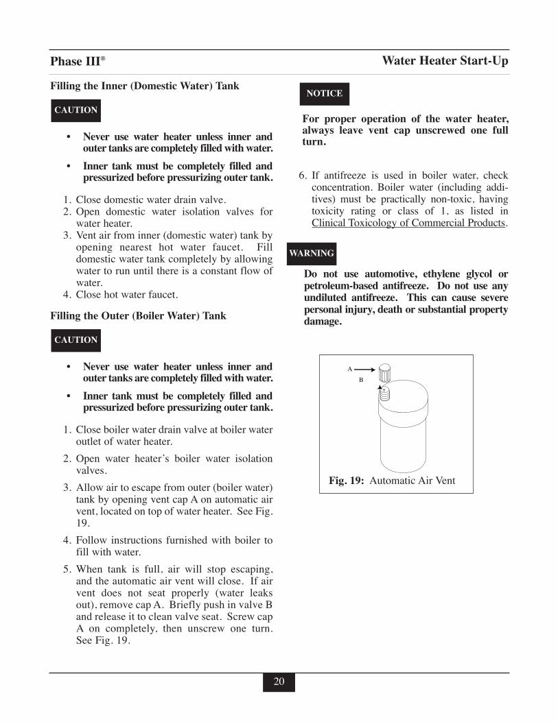
3. Allow air to escape from outer (boiler water)tank by opening vent cap A on automatic airvent, located on top of water heater. See Fig.19.
4. Follow instructions furnished with boiler tofill with water.
5. When tank is full, air will stop escaping,and the automatic air vent will close. If airvent does not seat properly (water leaksout), remove cap A. Briefly push in valve Band release it to clean valve seat. Screw capA on completely, then unscrew one turn.See Fig. 19.
For proper operation of the water heater,always leave vent cap unscrewed one fullturn.
6. If antifreeze is used in boiler water, checkconcentration. Boiler water (including addi-tives) must be practically non-toxic, havingtoxicity rating or class of 1, as listed inClinical Toxicology of Commercial Products.
Do not use automotive, ethylene glycol orpetroleum-based antifreeze. Do not use anyundiluted antifreeze. This can cause severepersonal injury, death or substantial propertydamage.
WARNING
NOTICE
CAUTION
CAUTION
A
B
Automatic Air VentFig. 19:

Phase III®
21
Water Heater Start-Up
HOT WATER CAN SCALD!
• Water temperatures over 125ºF can causesevere burns instantly, or death from scalds.
• Feel water before bathing or showering.
• Consumer Product Safety Commission andsome states recommend temperatures settings of130ºF or less. Setting thermostat higher than130ºF will increase risk of scald injury andcause severe personal injury or death.
• Water heated to a temperature suitable forclothes washing, dish washing and other sanitiz-ing needs will scald and cause permanent injury.
• Children and elderly, infirm, or physicallyhandicapped persons are more likely to beinjured by hot water. Never leave them unat-tended in or near a bathtub. If anyone using hotwater in the building fits this description, or ifstate laws or local codes require certain watertemperatures at hot water faucets, take specialprecautions.
- Install an automatic mixing valve at waterheater or at each hot water faucet, bath andshower outlet. Selection and installationmust comply with valve manufacturer’srecommendation and instructions.
- Use the lowest practical temperature setting.
- Check water temperature after any adjust-ment. You must follow “Adjusting theWater Heater Thermostat” procedures.
General Notes
• Household water usage patterns will affectwater temperature at any faucet or shower.Occasionally check temperature at each pointof use, then adjust thermostat accordingly.Always recheck temperature after adjustingthermostat.
• When hot water is used in repeated small quan-tities, a “stacking” effect can develop in thewater heater. The upper layer of water in tankcan be hotter than lower layer.
• Lowering the thermostat setting or installingautomatic mixing valves as indicated in theseinstructions will reduce water temperature levels.Consult your installer or service technician.
At no time should boiler limit control be setabove 210ºF. This can cause severe person-al injury, death or substantial propertydamage if ignored.
WARNING
DANGER
HOT
BURN
D A N G E R!

22
Phase III®
Adjusting the Water Heater Thermostat
Water heater thermostat is factory set to itslowest temperature. This may or may not besuitable for your needs.
Turn thermostat knob clockwise toincrease water temperature.Turn thermostat knob counter-clockwise to decrease water temperature.
Studies have indicated that dangerous bac-teria, including legionella, pneumophila, canform in the potable water distribution sys-tem if certain minimum water temperaturesare not maintained. Contact your localhealth department for more information.
• Check water temperature at a hot water faucetimmediately after first heating cycle. Furthertemperature adjustment may be necessary aswater heating system is used. Recheck watertemperature at faucet after adjustment.
• When adjusting thermostat, be sure boiler limitcontrol is set a minimum of 20ºF higher.
WARNING
Phase
III-
Phase
III - PhaseIII
-PhaseIII-
TemperatureDown
TemperatureUp
TemperatureUp
TemperatureDown
Water Heater Start-Up
TR Series Knob SMART Series Knob

Phase III®
23
Water Heater Maintenance
Maintenance Schedule
Annual service by qualified service technicianshould include the following:
Any procedure required by local codes.
Check air vent operation.
Verify system pressure. Air venting proce-dure may require adding water to bring sys-tem up to pressure, typically 12 psig.
Manually operate T&P relief valve at leastonce a year. This will release some hotwater.
Before operating T&P relief valve, makesure no one is in front of or around T&Prelief valve discharge piping. Hot dischargewater can cause severe personal injury orsubstantial property damage.
Move operating lever to open position for afew seconds and then move it back, allowing itto snap closed. After T&P relief valve is oper-ated, if it continues to release water, close coldwater inlet to water heater immediately.Follow draining instructions, and replace T&Prelief valve. If T&P relief valve weeps period-ically, it may be due to thermal expansion seeThermal Expansion, page 5. Do not plug T&Prelief valve or discharge piping.
Plugging T&P relief valve or discharge pip-ing can cause excessive pressure in waterheater, resulting in severe personal injury,death, or substantial property damage.
Follow instructions on circulator to oil it, ifrequired.
Check mixing valve, valves, pipes and fit-tings for leaks.
Check function of field-installed controlsand valves. See component manufacturer’sinstructions.
Review homeowner’s maintenance responsi-bilities and their frequencies, including anynot listed in the following section.
Homeowner monthly maintenance to include:
Check air vent operation.
• Automatic air vent - remove cap. Brieflypush in valve and release it to clean valveseat. Screw cap on completely, thenunscrew one full turn. If air vent does notoperate, call qualified service technician.
Visually check valves, pipes and fittings forleaks. Call qualified service technician torepair leaks.
Filling Water Heater
See “Filling the Inner (Domestic Water) Tank and“Filling the Outer (Boiler Water) Tank” on page 20.
Draining Water Heater
Drain water heater if it will be shut off and exposedto freezing temperatures. Freezing water willexpand and damage water heater.
• If boiler water contains sufficientantifreeze, then only the domestic waterneeds to be drained.
Close boiler water isolation valves andrelieve system pressure to below 15 psig inouter tank before draining inner tank toprevent damage to inner tank.
• If boiler water does not contain sufficientantifreeze, then the boiler water anddomestic water must be drained.
If antifreeze is used in boiler water, check concen-tration. Boiler water (including additives) must bepractically non-toxic, having toxicity rating orclass of 1, as listed in Clinical Toxicology ofCommercial Products. A maximum 50/50 mixtureof inhibited propylene glycol is recommended.Follow antifreeze manufacturer’s instruction.
WARNING
DANGER
WARNING

Phase III®
24
Water Heater Maintenance
Do not use automotive, ethylene glycol orpetroleum-based antifreeze. Do not useany undiluted antifreeze. This can causesevere personal injury, death or substantialproperty damage.
Water from opened drain valves, unionsand other connections may be extremelyhot. To avoid severe personal injury, deathor substantial property damage:
- Tighten all drain hose connections.
- Direct hot water away from all persons.
Draining Inner (Domestic Water) Tank
(See Domestic Piping Fig. 1 page 8)
1. Disconnect power supply to water heater.
- If outer (boiler water) tank pressureis greater than 15 psig, relieve boilerpressure and close isolation valvesbefore proceeding.
2. Close system supply isolation valve.
3. Connect a hose to domestic water drain valveat cold water inlet. Hose should extend todrain at floor level to allow siphoning ofdomestic water tank.
4. Open hot water faucet at highest point aboveheater.
5. Open domestic water drain valve to startsiphoning.
6. When draining is complete, close hot waterfaucet and domestic water drain valve.
Draining Outer (Boiler Water) Tank
1. Disconnect power supply to water heater.
2. Close boiler water isolation valves betweenboiler and water heater.
3. Connect hose to boiler water drain valve atwater heater. Open and drain water to a safeplace.
4. To speed draining procedure, loosen air venton top of tank.
5. When draining is complete, close drain valveand retighten air vent.
WARNING
WARNING

Phase III®
25
MODEL TR-20 TR-30 TR-36 TR-45 TR-60 TR-80 TR-100 TR-120Capacity Gal Domestic 20 30 36 46 56 76 95 119 Boiler 8 9 12 8 8 15 25 30Heating surface Sq. Ft. 12 15 18 20 24 28 34 42Head loss boiler side Ft. 3/4 3/4 1 1 1/4 1 1/2 2 2 2 1/2Piping connections Inches Domestic ø 3/4 3/4 3/4 3/4 1 1 1/2 1 1/2 1 1/2 Boiler ø 1 1 1 1 1/4 1 1/4 2 2 2 Recirculation ø 3/4 3/4 3/4 3/4 1 1 1/2 1 1/2 1 1/2Dimensions Inches A 14 32 42 39 49 42 53 52 B 38 49 60 57 67 62 72 72 C 19 19 19 23 23 24 26 30 D 19 19 19 23 23 24 27 30 E 7 3/4 7 3/4 7 3/4 14 14 10 3/4 10 3/4 10 3/4 F 10 10 10 10 10 12 12 12Drywell length Inches 31 39 51 39 51 51 51 51Empty weight Lbs 110 165 180 194 220 368 390 450
TR SERIES
Domestic HotWater Outlet
Domestic ColdWater Inlet
1/2" NPTAir Vent
Drywell for RemoteSensing Bulb
AuxiliaryConnection
C
D E
Water Heater Specifications
Boiler Water Return(TR-20 thru TR-36)Boiler Water Supply(TR-45 thru TR-120)
Boiler Water Supply(TR-20 thru TR-36)Boiler Water Return(TR-45 thru TR-120)
FA B
2"
Top views Side view
Domestic HotWater Outlet
Domestic ColdWater Inlet
1/2" NPTAir Vent
Drywell for RemoteSensing Bulb
AuxiliaryConnection
C
D E
4 1/8"
4 1/8"
TR-20/30/36/80/100/120
TR-45/60
Phase III®
26
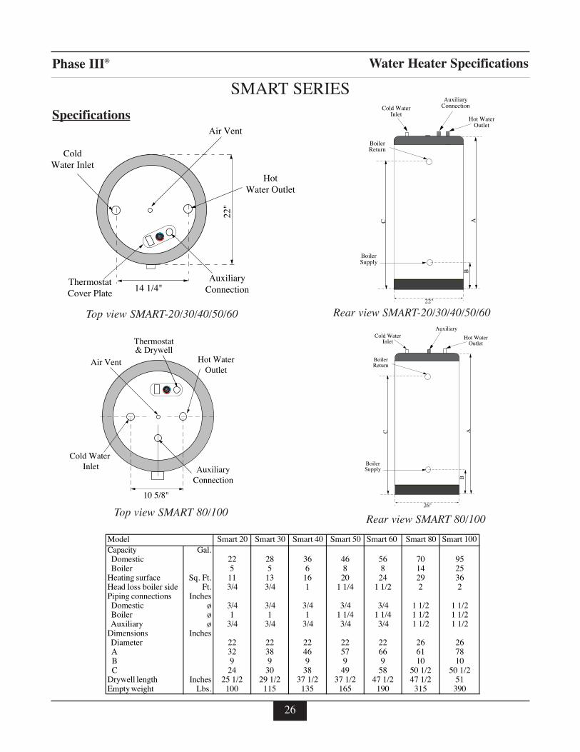
Model Smart 20 Smart 30 Smart 40 Smart 50 Smart 60 Smart 80 Smart 100Capacity Gal. Domestic 22 28 36 46 56 70 95 Boiler 5 5 6 8 8 14 25Heating surface Sq. Ft. 11 13 16 20 24 29 36Head loss boiler side Ft. 3/4 3/4 1 1 1/4 1 1/2 2 2Piping connections Inches Domestic ø 3/4 3/4 3/4 3/4 3/4 1 1/2 1 1/2 Boiler ø 1 1 1 1 1/4 1 1/4 1 1/2 1 1/2 Auxiliary ø 3/4 3/4 3/4 3/4 3/4 1 1/2 1 1/2Dimensions Inches Diameter 22 22 22 22 22 26 26 A 32 38 46 57 66 61 78 B 9 9 9 9 9 10 10 C 24 30 38 49 58 50 1/2 50 1/2Drywell length Inches 25 1/2 29 1/2 37 1/2 37 1/2 47 1/2 47 1/2 51Empty weight Lbs. 100 115 135 165 190 315 390
SMART SERIES
Specifications
Water Heater Specifications
22"
ColdWater Inlet
AuxiliaryConnection
ThermostatCover Plate
HotWater Outlet
Air Vent
14 1/4"
Top view SMART-20/30/40/50/60
BAC
22"
BoilerReturn
Hot WaterOutlet
Cold WaterInlet
AuxiliaryConnection
BoilerSupply
10 5/8"
Hot Water�Outlet
Cold Water Inlet Auxiliary
Connection
Thermostat& Drywell
Air Vent
Top view SMART 80/100Rear view SMART 80/100
Rear view SMART-20/30/40/50/60
BAC
26"
Cold WaterInlet
Hot WaterOutlet
Auxiliary
BoilerReturn
BoilerSupply

Phase III®
27
Model Boiler Heating Peak Flow 1st Hour Flow Continuous Flow Circulator Capacity MBH Gal./10 min. Gal./Hour Gal./Hour Min. GPM
TR-20 80 35 125 110 5TR-30 87 45 140 115 6TR-36 118 55 190 160 8TR-45 137 70 220 185 9TR-60 270 110 410 360 18TR-80 337 135 510 450 22TR-100 375 160 575 500 25TR-120 420 190 650 560 28
Model Boiler Heating Peak Flow 1st Hour Flow Continuous Flow Circulator Capacity MBH Gal./10 min. Gal./Hour Gal./Hour Min. GPM
SMART 20 70 35 110 95 5SMART 30 76 40 125 100 5SMART 40 106 50 170 140 7SMART 50 121 65 200 160 8SMART 60 243 100 370 325 16SMART 80 285 120 435 380 18SMART 100 337 150 525 450 25
Conditions: 50º F Domestic Cold Water Inlet Temperature140ºF Domestic Hot water Outlet Temperature200ºF Boiler Water Supply Temperature
Performances
Model Boiler Heating Peak Flow 1st Hour Flow Continuous Flow Circulator Capacity MBH Gal./10 min. Gal./Hour Gal./Hour Min. GPM
TR-20 105 50 210 190 7TR-30 120 60 245 220 8TR-36 145 75 300 270 10TR-45 190 95 390 350 13TR-60 335 150 665 620 22TR-80 365 175 730 670 24TR-100 400 200 825 750 28TR-120 445 235 915 820 30
Model Boiler Heating Peak Flow 1st Hour Flow Continuous Flow Circulator Capacity MBH Gal./10 min. Gal./Hour Gal./Hour Min. GPM
SMART 20 95 50 195 175 6SMART 30 115 60 235 210 8SMART 40 130 70 270 240 9SMART 50 180 95 370 330 12SMART 60 320 145 635 590 21SMART 80 340 165 690 630 24SMART 100 380 185 775 700 26
Conditions: 50º F Domestic Cold Water Inlet Temperature115ºF Domestic Hot water Outlet Temperature200ºF Boiler Water Supply Temperature

Phase III®
Code Descr ipt ion Model
P3AVT01 Air Vent (automatic) ALLP3KITTH01 Aquastat ALLP3BTMH3 Bottom Cap SMART 20-60P3BTMH2 Bottom Cap SMART 80/100P3TOPH3 Top Cap SMART 20-60P3TOPH2 Top Cap SMART 80/100P3CTNH20 Carton SMART 20-60P3CTNH30 Carton SMART 20-60P3CTNH36 Carton SMART 20-60P3CTNH45 Carton SMART 20-60P3CTNH60 Carton SMART 20-60P3CTNH80 Carton SMART 80/100WMDT01 Dip Tube with Diffuser SMART 20WMDT01 Dip Tube with Diffuser SMART 30WMDT02 Dip Tube with Diffuser SMART 40WMDT03 Dip Tube with Diffuser SMART 50WMDT04 Dip Tube with Diffuser SMART 60PEDT08 Dip Tube SMART 80/100P3DWH20 Dry Well SMART 20P3DW01 Dry Well SMART 30P3DW02 Dry Well SMART 40P3DW03 Dry Well SMART 50P3DW03 Dry Well SMART 60P3DW04 Dry Well SMART 80/100
28
Code Descr ipt ion Model
P3AVT01 Air Vent (automatic) ALLP3KITTH01 Aquastat ALLP3BP01 Base Plate TR-20/30/36P3BP02 Base Plate TR-45/60P3BP03 Base Plate TR-75P3BP04 Base Plate TR-100/120P3CS01 Control Panel TR-20/30/36P3CS02 Control Panel TR-45/60P3CS03 Control Panel TR-80P3CS05 Control Panel TR-100P3CS04 Control Panel TR-120P3DT02 Dip Tube TR-20P3DT04 Dip Tube TR-30P3DT10 Dip Tube TR-36P3DT05 Dip Tube TR-45P3DT06 Dip Tube TR-60P3DT08 Dip Tube TR-80P3DT09 Dip Tube TR-100/120P3DNK01 Drain Kit ALLP3DWT01 Drywell TR-20P3DWT02 Drywell TR-30P3DWT04 Drywell TR-36P3DWT02 Drywell TR-45P3DWT03 Drywell TR-60P3DWT04 Drywell TR-80P3DWT04 Drywell TR-100P3DWT04 Drywell TR-120P3JKT20F Jacket, Front Panel TR-20P3JKT30F Jacket, Front Panel TR-30P3JKT36F Jacket, Front Panel TR-36P3JKT45F Jacket, Front Panel TR-45P3JKT60F Jacket, Front Panel TR-60P3JKT75F Jacket, Front Panel TR-80P3JKT100F Jacket, Front Panel TR-100P3JKT120F Jacket, Front Panel TR-120P3JKT20B Jacket, Back Panel TR-20P3JKT30B Jacket, Back Panel TR-30P3JKT36B Jacket, Back Panel TR-36P3JKT45B Jacket, Back Panel TR-45P3JKT60B Jacket, Back Panel TR-60P3JKT75B Jacket, Back Panel TR-80P3JKT100B Jacket, Back Panel TR-100P3JKT120B Jacket, Back Panel TR-120P3JKT20L Jacket, Left Panel TR-20P3JKT30L Jacket, Left Panel TR-30P3JKT36L Jacket, Left Panel TR-36P3JKT45L Jacket, Left Panel TR-45P3JKT60L Jacket, Left Panel TR-60P3JKT75L Jacket, Left Panel TR-80P3JKT100L Jacket, Left Panel TR-100P3JKT120L Jacket, Left Panel TR-120P3JKT20R Jacket, Right Panel TR-20P3JKT30R Jacket, Right Panel TR-30P3JKT36R Jacket, Right Panel TR-36P3JKT45R Jacket, Right Panel TR-45P3JKT60R Jacket, Right Panel TR-60P3JKT75R Jacket, Right Panel TR-80P3JKT100R Jacket, Right Panel TR-100P3JKT120R Jacket, Right Panel TR-120P3LD01 Lid TR-20/30/36P3LD02 Lid TR-45/60P3LD03 Lid TR-80P3LD04 Lid TR-120P3LD05 Lid TR-100P3THR01 Thermometer ALLP3WRS01 Wire Harness & Snap Set ALL
Replacement Parts List
TR Series SMART Series

29
Phase III® Sample Specifications
TR_______or equal
1. Hot water tank designed for production of domestic hotwater using hot water as heating source. The principleconsists of two concentric tanks. The inner tank con-tains domestic hot water and the outer tank containsheating system water. The inner tank shall have a capac-ity of ________gallons.
2. The inner tank material shall be 304L corrugated stain-less steel or higher corrosion resistance stainless steel,and have a working pressure of 150 psi or more. Thecold water connection into this tank shall extend to nearthe bottom of the tank. The hot water connection shallbe at the top of the tank. Tank shall be designed to beself descaling.
3. The outer tank material shall be carbon steel with a builtin air vent. The working pressure shall be 45 psi max-imum.
4. The tank shall have a minimum of _________ squarefeet of heat transfer surface.
5. The outer tank shall have a minimum of 2 inches ofpolyurethane foam insulation or insulation with anequivalent “R” factor value installed on all sides.
6. The tanks shall be installed in a steel cabinet which hasbeen finished with a baked enamel paint.
7. The inner tank shall be equipped with a dry well. In thedry well shall be a remote sensing bulb to indicate watertemperature in the tank, and an additional remote sens-ing bulb for a low voltage thermostat. The thermostatshould be adjustable from low to high temperature.The thermostat shall open the circuit when the tempera-ture rises above the set point and shall close when thetemperature has no more than a (6) degree differentialbetween the opening temperature and the closing tem-perature.
8. Tank shall be installed with a temperature/pressurerelief valve. Valve shall relieve pressure at 150 psi.Relief temperature shall be 210 degrees.
SMART_______or equal
1. Hot water tank designed for production of domestic hotwater using hot water as heating source. The principleconsists of two concentric tanks. The inner tank containsdomestic hot water and the outer tank contains heatingsystem water. The inner tank shall have a capacityof________ gallons.
2. The inner tank material shall be 304L corrugated stain-less steel or higher corrosion resistance stainless steel,and have a working pressure of 150 psi or more. Thecold water connection into this tank shall extend to nearthe bottom of the tank. The hot water connection shallbe at the top of the tank. Tank shall be designed to beself descaling.
3. The outer tank material shall be carbon steel with a builtin air vent.The working pressure shall be 45 psi maxi-mum.
4. The tank shall have a minimum of __________square feet of heat transfer surface.
5. The outer tank shall have a minimum of 2 inches ofwater blown polyurethane insulation or insulation withan equivalent “R” factor value installed on all sides.
6. The tanks shall be covered by a plastic exterior jacket.
7. The inner tank shall be installed with a dry well. In thedry well shall be a remote sensing bulb for a low volt-age thermostat. The thermostat should be adjustablefrom low to high temperature. The thermostat shall openthe circuit when the temperature rises above the setpoint and shall close when the temperature has no morethan a (6) degree differential between the opening tem-perature and the closing temperature.
8. Tank shall be installed with a temperature/pressurerelief valve. Valve shall relieve pressure at 150 psi.Relief temperatures shall be 210 degrees.

Additional quality water heating equipment available from: Triangle Tube/Phase III
Phase III HM Series Water Heaters
- Stainless steel construction- Oil and Gas fired- A unique design that eliminates the problem of scal-
ing found with traditional water heaters- Inputs ranging from 100,000 BTU/hr to 382,000
BTU/hr- Capable of 180º continuous production- 10 year non-prorated warranty- ETL Laboratories listed- ASME version available
TTP Brazed Plate Heat Exchangers
- For domestic water, snow melting, radiant floor,refrigeration
- Plates made of stainless steel, with a 99.9 % copperand brazed, ensuring a high resistance to corrosion
- Self cleaning and self descaling- Computerized sizing available from Triangle
Tube/Phase III- Available in capacities from 25,000 BTU/hr to
5,000,000 BTU/hr- UL Listed
- Construction of high quality corrosion resistantstainless steel (AISI 316)
- Specially designed built-in flow restrictor to assuremaximum heat exchange
- Compact and light weight- Available in 5 sizes that can accommodate any size
pool or spa
Maxi-flo Pool and Spa Heat Exchangers
Freeway Center - 1 Triangle Lane - Blackwood, NJ 08012(856) 228 8881 Fax (856) 228 3584http:\\www.triangletube.com / e-mail: [email protected].
Member of
Group