tr a ill seassembly assembly requires two persons. set the treadmill in a cleared area and remove...
TRANSCRIPT

Model No. 831.24803.1Serial No.
Write the serial number in the spaceabove for future reference.
Serial NumberDecal
• Assembly
• Operation
• Maintenance
• Part List and Drawing
Sears, Roebuck and Co.,Hoffman Estates, IL 60179
TR A ILLUser's
SEManual

TABLE OF CONTENTS
WARNING DECAL PLACEMENT .............................................................. 2IMPORTANT PRECAUTIONS ................................................................. 3BEFORE YOU BEGIN ....................................................................... 5ASSEMBLY ............................................................................... 6OPERATION AND ADJUSTMENT ............................................................ 14HOW TO FOLD AND MOVE THE TREADMILL .................................................. 20TROUBLESHOOTING ...................................................................... 22EXERCISE GUIDELINES ................................................................... 25PART LIST ............................................................................... 26EXPLODED DRAWING ..................................................................... 28ORDERING REPLACEMENT PARTS .................................................. Back Cover90 DAY FULL WARRANTY ........................................................... Back Cover
WARNING DECAL PLACEMENT
This drawing shows the locations of the warningdecals, if a decal is missing or illegible, call1-888-533-1333 and request a free replace-ment decal. Apply the decal in the locationshown. Note: The decals may not be shown atactual size.
KEEPHANDSANDFEETAWAYFROMTHISAREAWHILETHETREADMILLISINOPERATION.
_rotect yourself andothers from risk of serious
injury. Read the user'smanual and :
•Stand only on theside rails when
.Hold handrails to
prevent falling, andalways weal thesafety clip whileoperating t/eadm II.
.Stop if you feel fa_t,dizzy, o[ short ofbreath.
• Fully engage storagelatch belo[e tread-mill _s moved orstored
,Reduce incline to _tslowest level before
folding treadmill _ntosto_age positbt,
•Never allowcbildren oF or
•Remove key whenr_otEnuse.
•Keep clothing,
_yf........Jog....... "Never trytoadiust
or lix the belt while
it _smovb_g.
_ .Always wearathlel c shoes while
operating t[eadm_ll,
iMPORTANT PRECAUTIONS
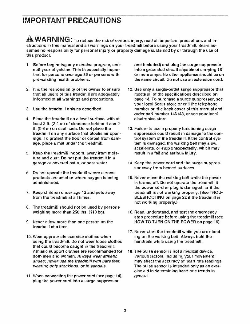
WARNING: Toreducetheriskofserious njury,reada, mportantprecautionsandstructions in this manual and all warnings on your treadmill before using your treadmill. Sears as-sumes no responsibility for personal injury or property damage sustained by or through the use ofthis product.
Before beginning any exercise program, con-sult your physician. This is especially impor-tant for persons over age 35 or persons withpre-existing health problems.
(not included) and plug the surge suppressorinto a grounded circuit capable of carrying 15or more amps. No other appliance should be onthe same circuit. Do not use an extension cord.
2. it is the responsibility of the owner to ensurethat all users of this treadmill are adequatelyinformed of all warnings and precautions.
3. Use the treadmill only as described.
. Place the treadmill on a level surface, with atleast 8 ft. (2.4 m) of clearance behind it and 2ft. (0.6 m) on each side. Do not place thetreadmill on any surface that blocks air open-ings. To protect the floor or carpet from dam-age, place a mat under the treadmill.
5. Keep the treadmill indoors, away from mois-ture and dust. Do not put the treadmill in agarage or covered patio, or near water.
6. Do not operate the treadmill where aerosolproducts are used or where oxygen is beingadministered.
7. Keep children under age 12 and pets awayfrom the treadmill at all times.
8. The treadmill should not be used by personsweighing more than 250 Ibs. (113 kg).
9. Never allow more than one person on thetreadmill at a time.
10. Wear appropriate exercise clothes whenusing the treadmill. Do not wear loose clothesthat could become caught in the treadmill.Athletic support clothes are recommended forboth men and women. Always wear athleticshoes; never use the treadmill with bare feet,wearing only stockings, or in sandals.
11. When connecting the power cord (see page 14),plug the power cord into a surge suppressor
12.
13.
14.
15.
16.
17.
18.
Use only a single-outlet surge suppressor thatmeets all of the specifications described onpage 14. To purchase a surge suppressor, seeyour local Sears store or call the telephonenumber on the back cover of this manual andorder part number 146148, or see your localelectronics store.
Failure to use a properly functioning surgesuppressor could result in damage to the con-trol system of the treadmill if the control sys-tem is damaged, the walking belt may slow,accelerate, or stop unexpectedly, which mayresult in a fall and serious injury.
Keep the power cord and the surge suppres-sor away from heated surfaces.
Never move the walking belt while the poweris turned off. Do not operate the treadmill ifthe power cord or plug is damaged, or if thetreadmill is not working properly. (See TROU-BLESHOOTING on page 22 if the treadmill isnot working properly.)
Read, understand, and test the emergencystop procedure before using the treadmi!l (seeHOW TO TURN ON THE POWER on page 16).
Never start the treadmill while you are stand=ing on the walking belt. Always hold thehandrails while using the treadmill
The pulse sensor is not a medical device.Various factors, including your movement,may affect the accuracy of heart rate readings.The pulse sensor is intended only as an exer-cise aid in determining heart rate trends ingeneral.

19.The treadmill is capable of high speeds.Adjust the speed in small increments to avoidsudden jumps in speed.
20. Never leave the treadmill unattended while it
is running. Always remove the key, unplugthe power cord, and switch the reset/off cir-cuit breaker to the off position when thetreadmill is not in use. (See the drawing onpage 5 for the location of the circuit breaker.)
21. Do not attempt to raise, lower, or move thetreadmill until it is properly assembled. (SeeASSEMBLY on page 6 and HOW TO FOLDAND MOVE THE TREADMILL on page 20.)You must be able to safely lift 45 Ibs. (20 kg)to raise, lower, or move the treadmill.
22. When folding or moving the treadmill, makesure that the storage latch is holding theframe securely in the storage position.
23. Do not change the incline of the treadmill byplacing objects under the treadmill.
SAVE THESE
24.
25.
26.
27.
inspect and properly tighten all parts of thetreadmill regularly.
Never drop or insert any object into anyopening on the treadmill.
This treadmill is intended for in-home use
only. Do not use this treadmill in a commer-cial, rental, or institutional setting.
DANGER: A waysunplugthepowercord immediately after use, before cleaningthe treadmill, and before performing the main-tenance and adjustment procedures de-scribed in this manual. Never remove themotor hood unless instructed to do so by anauthorized service representative. Servicingother than the procedures in this manualshould be performed by an authorized servicerepresentative only.
iNSTRUCTiONS
4
BEFORE YOU BEGIN
Thank you for selecting the new PROFORM ®CROSS-WALK 380 treadmill. The CROSSWALK 380 treadmill
offers a selection of features designed to make yourworkouts at home more effective and enjoyable. Andwhen you're not exercising, the treadmill can be foldedup, requiring less than half the floor space of othertreadmills.
For your benefit, read this manual carefully beforeusing the treadmill. If you have questions after read-
ing this manual, please see the back cover of thismanual. To help us assist you, note the product modelnumber and serial number before contacting us. Themodel number and the location of the serial numberdecal are shown on the front cover of this manual.
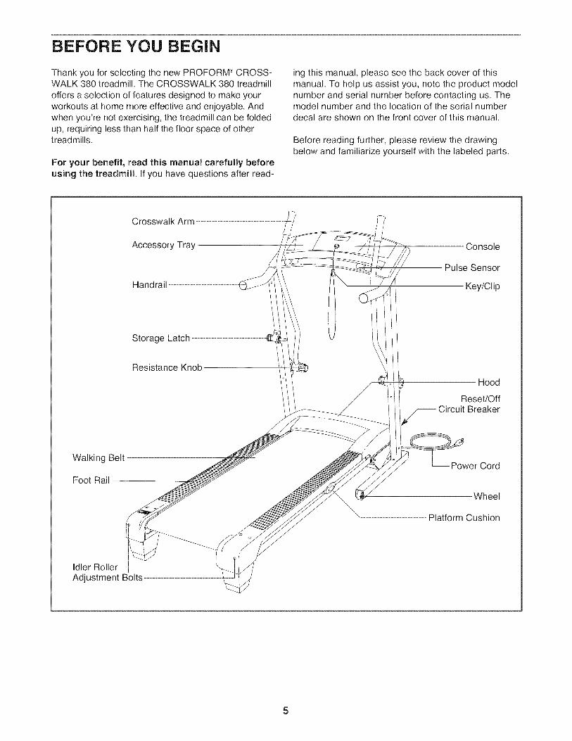
Before reading further, please review the drawingbelow and familiarize yourself with the labeled parts.
Crosswalk Arm
Accessory Tray
Handrail
Storage Latch
Resistance Knob
Console
Pulse Sensor
Key/Clip
Hood
Reset/OffCircuit Breaker
Walking Belt
Foot Rail
-- Power Cord
Wheel
Platform Cushion
Idler RollerAdjustment Bolts
5
ASSEMBLY
Assembly requires two persons. Set the treadmill in a cleared area and remove all packing materials. Do notdispose of the packing materials until assembly is completed. Note: The underside of the treadmill walkingbelt is coated with high-performance lubricant. During shipping, a small amount of lubricant may be transferred tothe top of the walking belt or the shipping carton. This is a normal condition and does not affect treadmill perfor-mance. If there is lubricant on top of the walking belt, simply wipe off the lubricant with a soft cloth and a mild,non-abrasive cleaner.
Assembly requires the included hex_ and your own Phillips screwdriver _L_====_, adjustable
wrench _, scissors _=_, needlenose pliers _, and rubber mallet _.
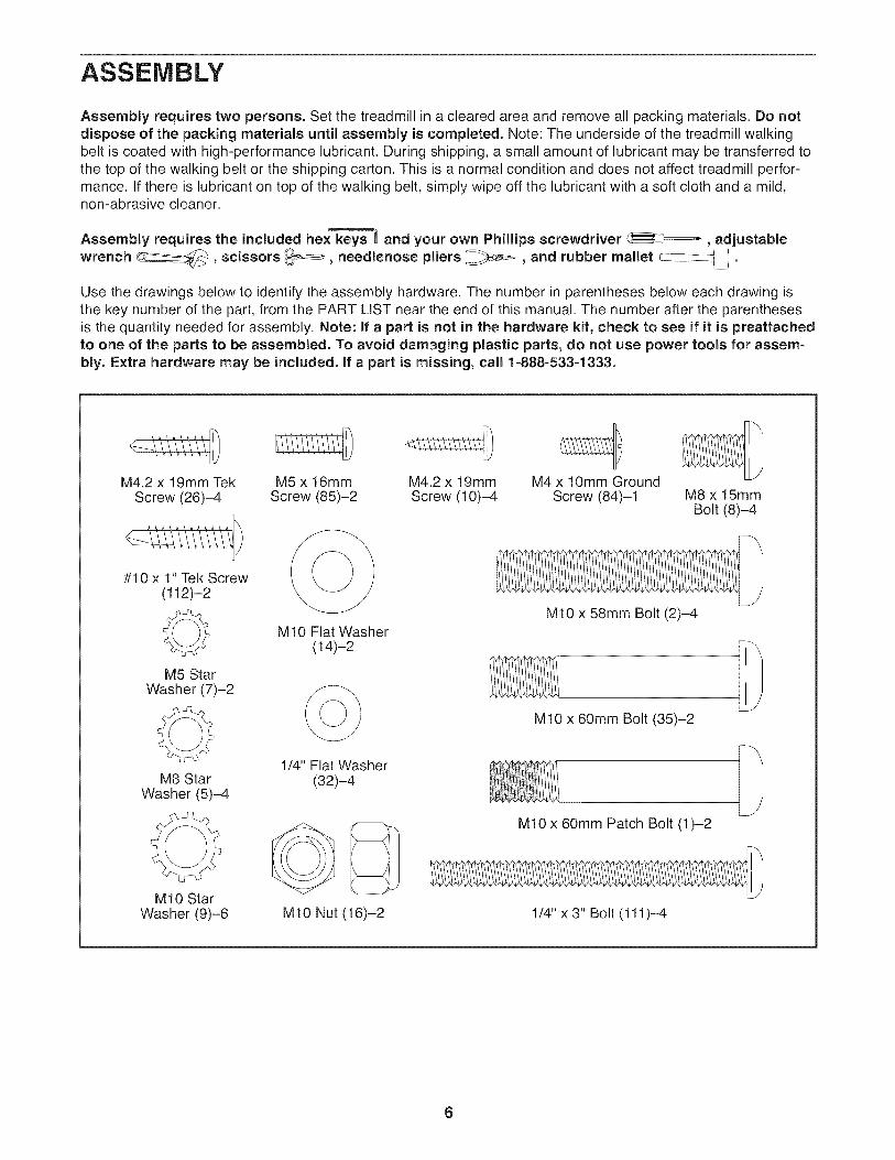
Use the drawings below to identify the assembly hardware. The number in parentheses below each drawing isthe key number of the part, from the PART LIST near the end of this manual. The number after the parenthesesis the quantity needed for assembly. Note: if a part is not in the hardware kit, check to see if it is preattachedto one of the parts to be assembled. To avoid damaging plastic parts, do not use power tools for assem-bly. Extra hardware may be included, if a part is missing, call 1-888-533-1333.
M4.2 x 19mm TekScrew (26)-4
#10 x 1" Tek Screw(112)-2
©M5 Star
Washer (7)-2
M8 StarWasher (5)-4
M10 StarWasher (9)-6
M5 x 16mm M4.2 x 19mm M4 x 10mm GroundScrew (85)-2 Screw (10)-4 Screw (84)-1 M8 x 15mm
Bolt (8)-4
M10 Flat Washer(14)-2
1/4" Flat Washer(32)-4
M10 Nut (16)-2
M10 x 58mm Bolt (2)-4
M10 x 60mm Bolt (35)-2
M10 x 60mm Patch Bolt (1)-2
1/4" x 3" Bolt (111)-4
6

. Make sure that the power cord is unplugged.
Position the Base (52) upside-down as shown.
Attach four Base Feet (63) to the Base (52) withfour M4.2 x 19mm Tek Screws (26).
26
26
52
26
2. Attach the Wheels (70) to the Base (52) with twoM10 Nuts (16), two M10 x 60mm Bolts (35) andfour Wheel Spacers (69) as shown, Do not over-tighten the Nuts; the Wheels should turnfreely.
2
35
6
69 16
69
70 69
52
35
3. Have a second person hold the Base (52) in theposition shown.
Identify the Left Upright (53) (the Right Upright[54] has a square hole near the lower end).
Hold the Left Upright (53) so that the smallholes are positioned as shown. Attach the LeftUpright (53) to the Base (52) with two M10 x58mm Bolts (2) and two M10 Star Washers (9);do not fully tighten the Bolts yet.
Attach the Right Upright (54) to the Base (52)in the same way.
3
SmallHoles
53
SqlHole
54
52
9
2A
7

4. 4Position the Base (52) as close to the front of thetreadmill as possible, as shown.
See the upper inset drawing. Locate the wiretie in the lower end of the Right Upright (54). Tiethe wire tie securely around the end of the WireHarness (39). Then, locate the other end of thewire tie in the upper end of the Right Upright.Pull the upper end of the wire tie until the WireHarness extends from the upper end of the RightUpright. Secure the Wire Harness to the RightUpright so that it will not fall inside.
See the lower inset drawing. Press the indi-cated Grommet (49) into the Right Upright (54).
54
52
39
49
Tie
. See the left inset drawing. Identify the twoFrame Spacers (11). Open the included packetof grease, and apply grease to both sides of bothFrame Spacers. Then, identify the outer side ofeach Frame Spacer.
Hold a Frame Spacer (11) between the RightUpright (54) and the Lift Frame (23), with theouter side of the Frame Spacer facing theRight Upright.
With the help of a second person, lift the front ofthe treadmill. Attach the Lift Frame (23) to theRight Upright (54) with an M10 x 60mm PatchBolt (1), an M10 Flat Washer (14), and an M10Star Washer (9); do not fully tighten the PatchBolt yet.
5 /'
1 1
/Outer Side
Top View
/
23 / 9
[--54
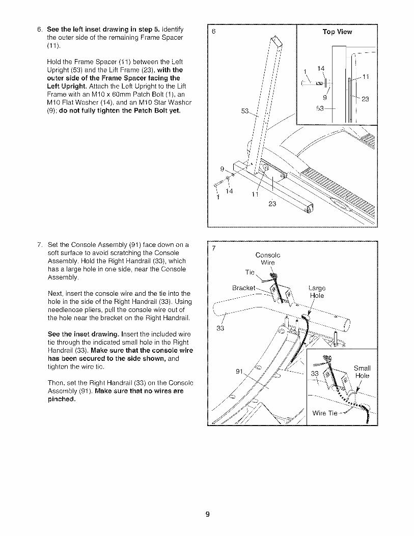
. See the left inset drawing in step 5. identifythe outer side of the remaining Frame Spacer(11).
Hold the Frame Spacer (11) between the LeftUpright (53) and the Lift Frame (23), with theouter side of the Frame Spacer facing theLeft Upright. Attach the Left Upright to the LiftFrame with an M10 x 60mm Patch Bolt (1), anM10 Flat Washer (14), and an M10 Star Washer(9); do not fully tighten the Patch Bolt yet.
14 11
23
Top View
. Set the Console Assembly (91) face down on asoft surface to avoid scratching the ConsoleAssembly. Hold the Right Handrail (33), whichhas a large hole in one side, near the ConsoleAssembly.
Next, insert the console wire and the tie into thehole in the side of the Right Handrail (33). Usingneedlenose pliers, pull the console wire out ofthe hole near the bracket on the Right Handrail.
See the inset drawing, insert the included wiretie through the indicated small hole in the RightHandrail (33). Make sure that the console wirehas been secured to the side shown, andtighten the wire tie.
Then, set the Right Handrail (33) on the ConsoleAssembly (91). Make sure that no wires arepinched.
33
ConsoleWire
Tie\
91
LargeHole
Wire Tie
SmallHole
9

. Start an M5 x 16mm Screw (85) with an M5 StarWasher (7) into the Right Handrail (33), andthen start two M4.2 x 19mm Screws (10) into theRight Handrail. Tighten the M5 x 16ram Screwand then tighten the two IVl4.2 x 19ramScrews; do not overtighten the Screws.
Set the Left Handrail (not shown) on the ConsoleAssembly (91). Attach the Left Handrail to theConsole Assembly in the same way. Note:There are no wires on the left side.
33
91
85
$7 10
. Remove the ties from the Cage Nuts (105) in theRight Handrail (33) and the Left Handrail (notshown). If necessary, press the Cage Nuts backinto place. With the help of a second person, holdthe Console Assembly (91) near the Right Upright(54).
Connect the Wire Harness (39) to the consolewire. See the inset drawing. The connectorsshould slide together easily and snap intoplace. If they do not, turn one connector and tryagain. IF THE CONNECTORS ARE NOT CON-NECTED PROPERLY, THE CONSOLE MAYBE DAMAGED WHEN THE POWER iSTURNED ON. Insert the connectors and the ex-
cess wire downward into the Right Upright (54).Remove the wire tie from the Wire Harness.
33
ConsoleWire Wire..
Wire/Tie
10
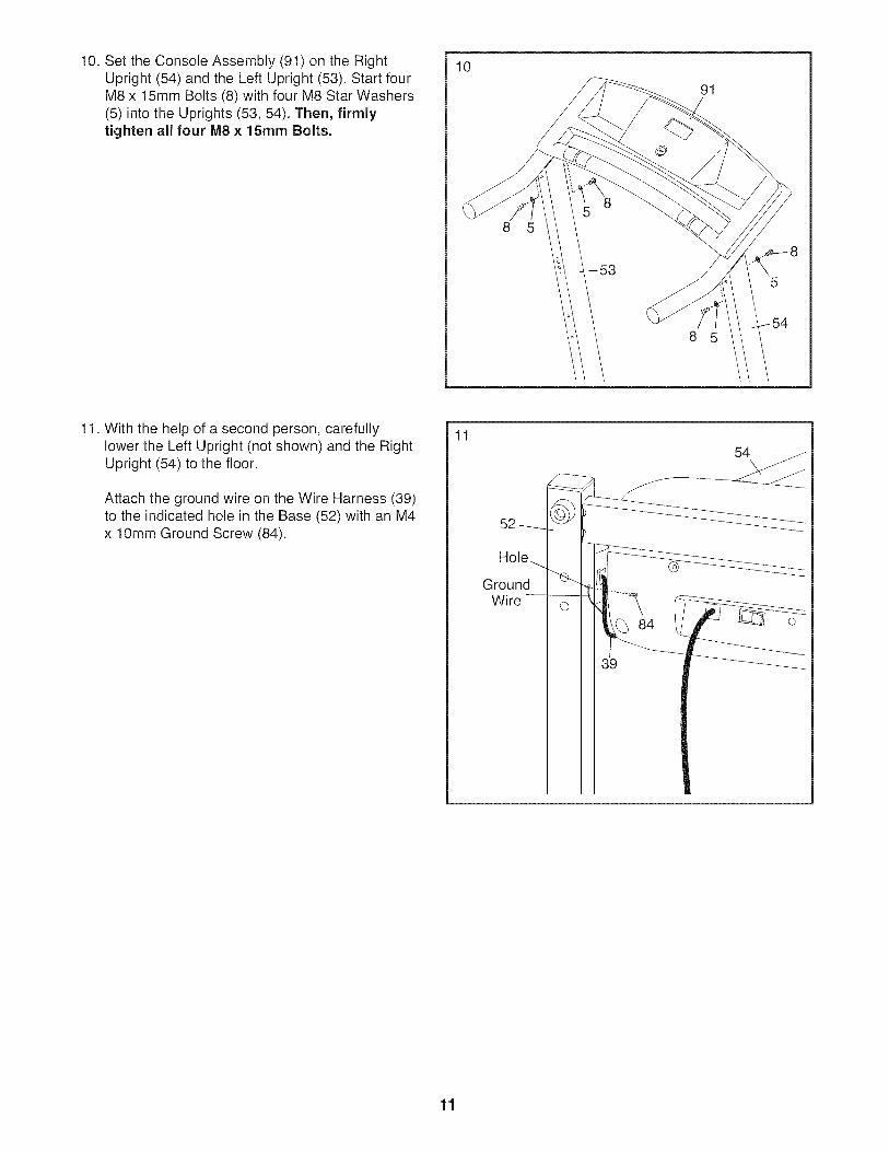
10. Set the Console Assembly (91) on the RightUpright (54) and the Left Upright (53). Start fourM8 x 15mm Bolts (8) with four M8 Star Washers(5) into the Uprights (53, 54). Then, firmlytighten all four IV18x 15ram Bolts.
10
5
91
8
11. With the help of a second person, carefullylower the Left Upright (not shown) and the RightUpright (54) to the floor.
Attach the ground wire on the Wire Harness (39)to the indicated hole in the Base (52) with an M4x 10mm Ground Screw (84).
11
52
GroundWire
84
39
54
11

12. See the lower drawing. Position the Uprights(53, 54) so that the Frame (51) is centered be-tween them.
Firmly tighten the two M10 x 60mm Patch Bolts(1) and the four M10 x 58mm Bolts (2) (only oneside is shown), Be careful not to overtightenthe M10 x 60ram Patch Bolts. Raise the
Uprights (53, 54).
12
54
53, 54
Top View
51 53
13. Attach the Latch Housing (48) to the LeftUpright (53) with two #10 x 1" Tek Screws(112); start both Tek Screws before tighten-ing either of them. Make sure that the largehole in the Latch Housing is on the indicatedside.
Locate the Latch Pin Assembly (24), Removethe knob from the pin, Make sure that the collarand the spring are on the pin. (Note: if there aretwo collars, place one on each side of thespring.) Insert the pin into the Latch Housing(48). Then, tighten the knob onto the pin.
13
112
Large Hole
Collar
Pin
12

14. Attach the Left Crosswalk Arm (73) to the LeftUpright (53) with two 1/4" Flat Washers (32) andtwo 1/4" x 3" Bolts (111). Make sure that the LeftCrosswalk Arm is on the indicated side of theConsole Assembly (91).
Attach the Right Crosswalk Arm (not shown)in the same way. Be careful not to pinch thewires in the Right Upright (not shown).
14
111
73
32
15. Make sure that all parts are properly tightened before you use the treadmill. Keep the included hex keysin a secure place. One hex key is used to adjust the walking belt (see page 23). To protect the floor or carpet,place a mat under the treadmill.
13
OPERATION AND ADJUSTMENT
THE PRE-LUBRICATED WALKING BELT
Your treadmill features a walking belt coated with high-performance lubricant. IMPORTANT: Never apply sil-icone spray or other substances to the walkingbelt or the walking platform. Such substances willdeteriorate the walking belt and cause excessivewear.
HOW TO PLUG IN THE POWER CORD
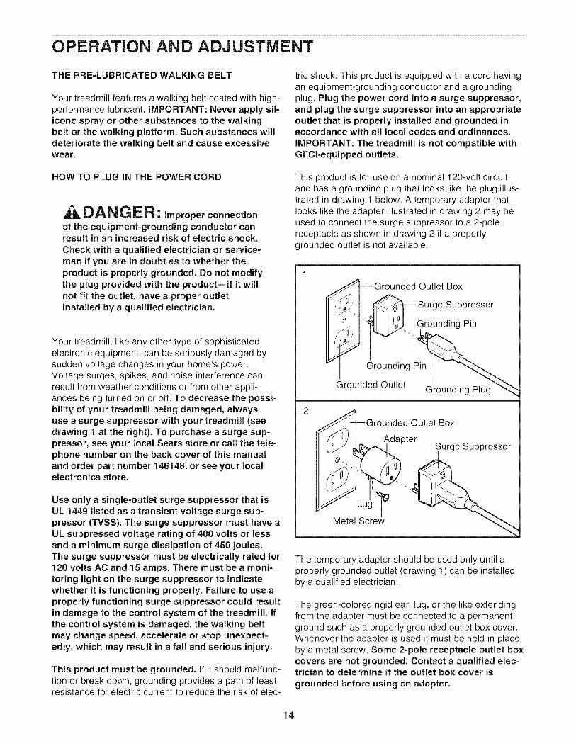
A DAN G ER: Improperconnectionof the equipment-grounding conductor canresult in an increased risk of electric shock.
Check with a qualified electrician or service-man if you are in doubt as to whether theproduct is properly grounded. Do not modifythe plug provided with the product--if it willnot fit the outlet, have a proper outletinstalled by a qualified electrician.
Your treadmill, like any other type of sophisticatedelectronic equipment, can be seriously damaged bysudden voltage changes in your home's power.Voltage surges, spikes, and noise interference canresult from weather conditions or from other appli-ances being turned on or off. To decrease the possi-bility of your treadmill being damaged, alwaysuse a surge suppressor with your treadmill (seedrawing 1 at the right). To purchase a surge sup-pressor, see your local Sears store or call the tele-phone number on the back cover of this manualand order part number 146148, or see your localelectronics store.
Use only a single-outlet surge suppressor that isUL 1449 listed as a transient voltage surge sup-pressor (TVSS). The surge suppressor must have aUL suppressed voltage rating of 400 volts or lessand a minimum surge dissipation of 450 joules.The surge suppressor must be electrically rated for120 volts AC and 15 amps. There must be a moni-toring light on the surge suppressor to indicatewhether it is functioning properly. Failure to use aproperly functioning surge suppressor could resultin damage to the control system of the treadmill. Ifthe control system is damaged, the walking beltmay change speed, accelerate or stop unexpect-edly, which may result in a fall and serious injury.
This product must be grounded, if it should malfunc-tion or break down, grounding provides a path of leastresistance for electric current to reduce the risk of elec-
tric shock. This product is equipped with a cord havingan equipment-grounding conductor and a groundingplug. Plug the power cord into a surge suppressor,and plug the surge suppressor into an appropriateoutlet that is properly installed and grounded inaccordance with all local codes and ordinances.
IMPORTANT: The treadmill is not compatible withGFCI-equipped outlets.
This product is for use on a nominal 120-volt circuit,and has a grounding plug that looks like the plug illus-trated in drawing 1 below. A temporary adapter thatlooks like the adapter illustrated in drawing 2 may beused to connect the surge suppressor to a 2-polereceptacle as shown in drawing 2 if a properlygrounded outlet is not available.
_Grounded Outlet Box
_,_ _", 1 _ Surge Suppressor
II _ _'_ _J Grounding Pin
Grounded Outlet G_ounding Plug
2
_A-1--Grounded Outlet Box/ /n_ I
/[1 _J I Adapter =
___. Surge suppressor
Metal Screw _
The temporary adapter should be used only until aproperly grounded outlet (drawing 1) can be installedby a qualified electrician.
The green-colored rigid ear, lug, or the like extendingfrom the adapter must be connected to a permanentground such as a properly grounded outlet box cover.Whenever the adapter is used it must be held in placeby a metal screw. Some 2-pole receptacle outlet boxcovers are not grounded. Contact a qualified elec-trician to determine if the outlet box cover is
grounded before using an adapter.
14

CONSOLEDIAGRAM
Ke
FEATURES OFTHECONSOLE
The treadmill console offers a selection of featuresdesigned to make your workouts more effective. Whenyou select the manual mode of the console, you canchange the speed and incline of the treadmill with thetouch of a button. As you exercise, the displays willprovide continuous exercise feedback. You can evenmeasure your heart rate using the built-in pulse sensor.
The console also features three preset speed and in-cline workouts. Each workout controls the speed andincline of the treadmill as it guides you through an ef-fective exercise session. In addition, the console offersthree preset crosswalk workouts that automatically con-trol the speed and incline of the treadmill and promptyou to use the crosswalk arms for a total body workout.
To turn on the power, see page 16. To use the man-ual mode, see page 16. To use a preset workout,
see page 18. To use the information mode, seepage 19.
iMPORTANT: If there is a sheet of clear plastic onthe face of the console, remove the plastic. To pre-vent damage to the walking platform, wear cleanathletic shoes while using the treadmill. The firsttime the treadmill is used, observe the alignment ofthe walking belt, and center the walking belt if nec-essary (see page 23).
Note: The console can display speed and distance ineither miles or kilometers. To find which unit of mea-surement is selected or to change the unit of measure-ment, see THE INFORMATION MODE on page 19.For simplicity, all instructions in this manual refer tomiles.
15

HOW TO TURN ON THE POWER HOW TO USE THE MANUAL MODE
iMPORTANT: if the treadmill has been exposed tocold temperatures, allow it to warm to room tem-perature before turning on the power, if you do notdo this, you may damage the console displays orother electrical components.
Plug in the power cord (seepage 14). Next, locate thereset/off circuit breaker onthe treadmill frame near the
power cord. Switch the cir-cuit breaker to the reset po-sition.
ResetPosition
iMPORTANT: The console features a display demomode, designed to be used if the treadmill is dis-played in a store, if the displays light as soon asyou plug in the power cord and switch the reset/offcircuit breaker to the reset position, the demomode is turned on. To turn off the demo mode,hold down the Stop button for a few seconds. If thedisplays remain lit, see THE INFORMATION MODEon page 19 to turn off the demo mode.
Next, stand on the foot rails of the treadmill. Find theclip attached to the key (see the drawing on page 15)and slide the clip onto the waistband of your clothes.Then, insert the key into the console. After a moment,the displays will light. IMPORTANT: In an emergencysituation, the key can be pulled from the console,causing the walking belt to slow to a stop. Test theclip by carefully taking a few steps backward; if thekey is not pulled from the console, adjust the posi-tion of the clip.
1. insert the key into the console.
See HOW TO TURN ON THE POWER at the left.
2. Select the manual mode.
When the key is inserted,the manual mode will be
selected. If you have se-lected a speed workout,reselect the manual
mode by pressing one of
U'ULJ
U,_..J U U OtST,J
the Select buttons repeatedly until only zeros ap-pear in the displays.
3. Start the walking belt.
To start the walking belt, press the Start button orthe Speed increase button. The walking belt willbegin to move at 1 mph. As you exercise, changethe speed of the walking belt as desired by press-ing the Speed increase and decrease buttons.Each time you press a button, the speed settingwill change by 0.1 mph; if you hold down a button,the speed setting will change in increments of 0.5mph. Note: After you press the buttons, it may take amoment for the walking belt to reach the selectedspeed setting.
To stop the walking belt, press the Stop button. Ifthe time is shown, the time will begin to flash in thedisplay. To restart the walking belt, press the Startbutton or the Speed increase button.
4. Change the incline of the treadmill as desired.
To change the incline ofthe treadmill, press theIncline increase or de-crease button. Each time
you press one of the but-tons, the incline will grad-ually increase or decrease until it reaches the se-lected incline setting.
16
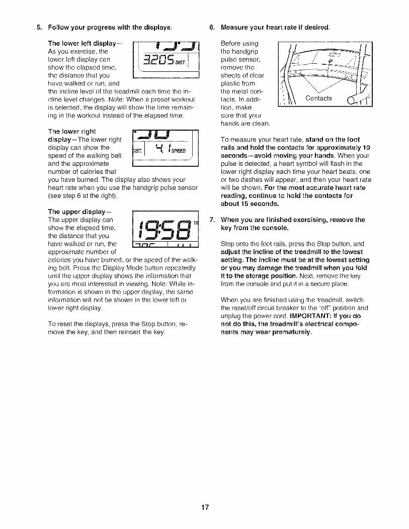
5. Follow your progress with the displays. 6. Measure your heart rate if desired.
The lower left display--As you exercise, thelower left display canshow the elapsed time,the distance that youhave walked or run, andthe incline level of the treadmill each time the in-
cline level changes. Note: When a preset workoutis selected, the display will show the time remain-ing in the workout instead of the elapsed time.
The lower rightdisplay--The lower rightdisplay can show thespeed of the walking beltand the approximatenumber of calories that
you have burned. The display also shows yourheart rate when you use the handgrip pulse sensor(see step 6 at the right).
The upper display--The upper display canshow the elapsed time,the distance that youhave walked or run, theapproximate number ofcalories you have burned, or the speed of the walk-ing belt. Press the Display Mode button repeatedlyuntil the upper display shows the information thatyou are most interested in viewing. Note: While in-formation is shown in the upper display, the sameinformation will not be shown in the lower left or
lower right display.
To reset the displays, press the Stop button, re-move the key, and then reinsert the key.
Before usingthe handgrippulse sensor,remove thesheets of clear
plastic fromthe metal con-tacts. In addi-tion, makesure that yourhands are clean.
To measure your heart rate, stand on the footrails and hold the contacts for approximately 10seconds--avoid moving your hands. When yourpulse is detected, a heart symbol will flash in thelower right display each time your heart beats, oneor two dashes will appear, and then your heart ratewill be shown. For the most accurate heart rate
reading, continue to hold the contacts forabout 15 seconds.
7. When you are finished exercising, remove thekey from the console.
Step onto the foot rails, press the Stop button, andadjust the incline of the treadmill to the lowestsetting. The incline must be at the lowest settingor you may damage the treadmill when you foldit to the storage position. Next, remove the keyfrom the console and put it in a secure place.
When you are finished using the treadmill, switchthe reset/off circuit breaker to the "off" position andunplug the power cord. IMPORTANT: If you donot do this, the treadmill's electrical compo-nents may wear prematurely.
17
HOW TO USE A PRESET WORKOUT
1. Insert the key into the console.
See HOW TO TURN ON THE POWER on page16.
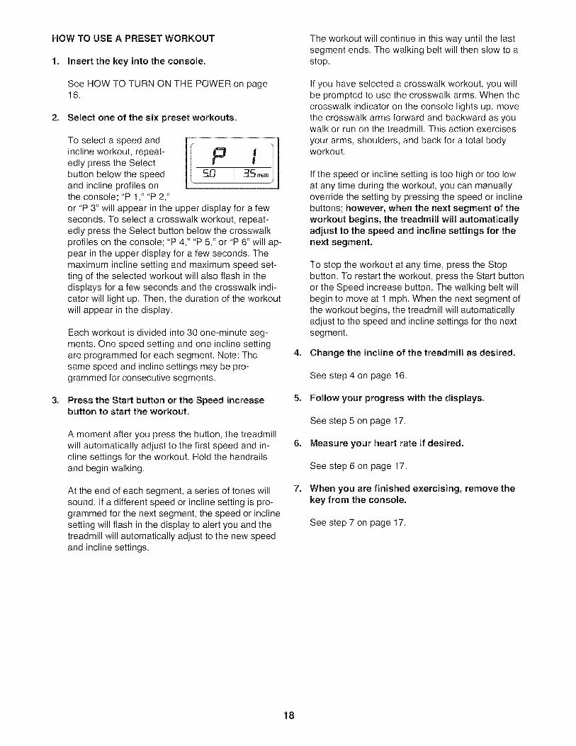
2. Select one of the six preset workouts.
To select a speed andincline workout, repeat-edly press the Selectbutton below the speedand incline profiles onthe console; "P 1," "P 2,"
P fso
J
or "P 3" will appear in the upper display for a fewseconds. To select a crosswalk workout, repeat-edly press the Select button below the crosswalkprofiles on the console; "P 4," "P 5," or "P 6" will ap-pear in the upper display for a few seconds. Themaximum incline setting and maximum speed set-ting of the selected workout will also flash in thedisplays for a few seconds and the crosswalk indi-cator will light up. Then, the duration of the workoutwill appear in the display.
Each workout is divided into 30 one-minute seg-ments. One speed setting and one incline settingare programmed for each segment. Note: Thesame speed and incline settings may be pro-grammed for consecutive segments.
3. Press the Start button or the Speed increasebutton to start the workout.
A moment after you press the button, the treadmillwill automatically adjust to the first speed and in-cline settings for the workout. Hold the handrailsand begin walking.
At the end of each segment, a series of tones willsound. If a different speed or incline setting is pro-grammed for the next segment, the speed or inclinesetting will flash in the display to alert you and thetreadmill will automatically adjust to the new speedand incline settings.
The workout will continue in this way until the lastsegment ends. The walking belt will then slow to astop.
If you have selected a crosswalk workout, you willbe prompted to use the crosswalk arms. When thecrosswalk indicator on the console lights up, movethe crosswalk arms forward and backward as youwalk or run on the treadmill. This action exercises
your arms, shoulders, and back for a total bodyworkout.
If the speed or incline setting is too high or too lowat any time during the workout, you can manuallyoverride the setting by pressing the speed or inclinebuttons; however, when the next segment of theworkout begins, the treadmill will automaticallyadjust to the speed and incline settings for thenext segment.
To stop the workout at any time, press the Stopbutton. To restart the workout, press the Start buttonor the Speed increase button. The walking belt willbegin to move at 1 mph. When the next segment ofthe workout begins, the treadmill will automaticallyadjust to the speed and incline settings for the nextsegment.
4. Change the incline of the treadmill as desired.
See step 4 on page 16.
5. Follow your progress with the displays.
See step 5 on page 17.
6. Measure your heart rate if desired.
See step 6 on page 17.
7. When you are finished exercising, remove thekey from the console.
See step 7 on page 17.
18
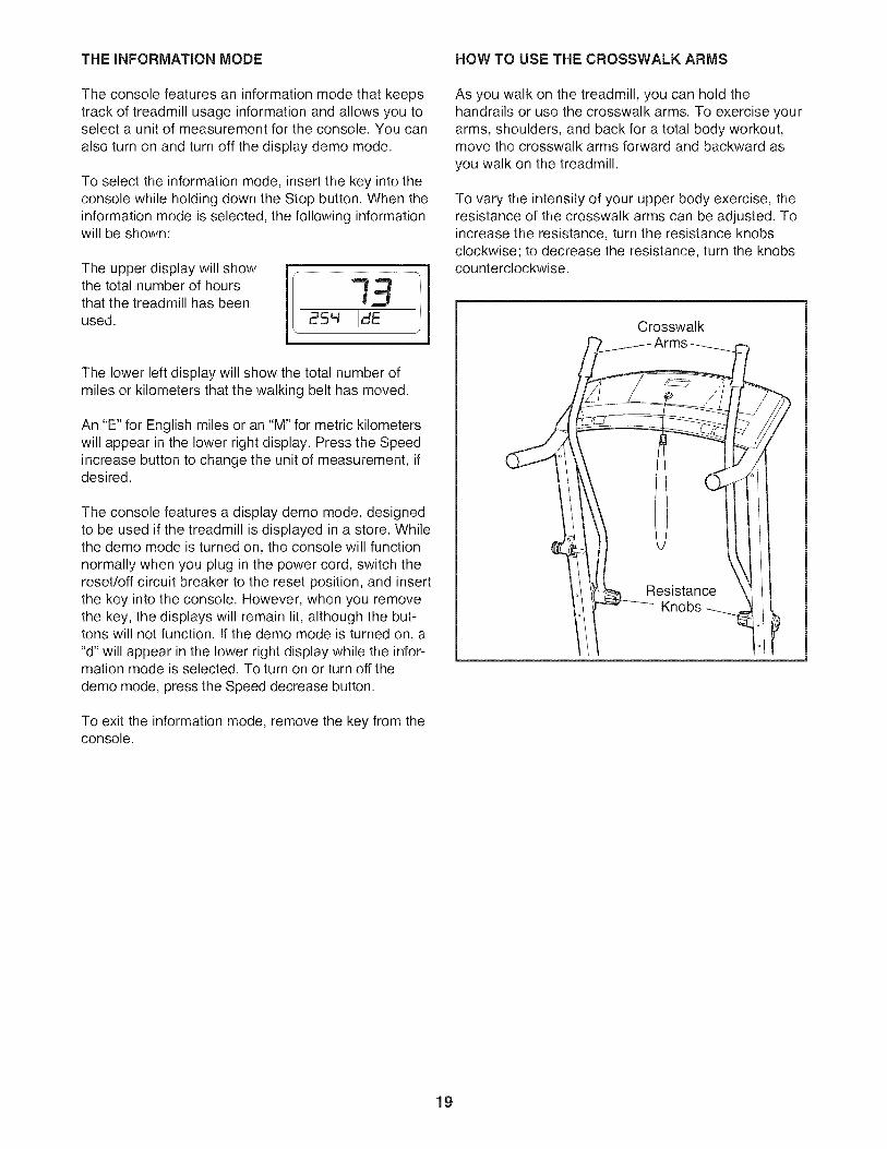
THE iNFORMATiON MODE HOW TO USE THE CROSSWALK ARMS
The console features an information mode that keepstrack of treadmill usage information and allows you toselect a unit of measurement for the console. You can
also turn on and turn off the display demo mode.
To select the information mode, insert the key into theconsole while holding down the Stop button. When theinformation mode is selected, the following informationwill be shown:
The upper display will showthe total number of hoursthat the treadmill has beenused.
The lower left display will show the total number ofmiles or kilometers that the walking belt has moved.
An "E" for English miles or an "M" for metric kilometerswill appear in the lower right display. Press the Speedincrease button to change the unit of measurement, ifdesired.
The console features a display demo mode, designedto be used if the treadmill is displayed in a store. Whilethe demo mode is turned on, the console will functionnormally when you plug in the power cord, switch thereset/off circuit breaker to the reset position, and insertthe key into the console. However, when you removethe key, the displays will remain lit, although the but-tons will not function. If the demo mode is turned on, a"d" will appear in the lower right display while the infor-mation mode is selected. To turn on or turn off the
demo mode, press the Speed decrease button.
To exit the information mode, remove the key from theconsole.
As you walk on the treadmill, you can hold thehandrails or use the crosswalk arms. To exercise yourarms, shoulders, and back for a total body workout,move the crosswalk arms forward and backward as
you walk on the treadmill.
To vary the intensity of your upper body exercise, theresistance of the crosswalk arms can be adjusted. Toincrease the resistance, turn the resistance knobsclockwise; to decrease the resistance, turn the knobscounterclockwise.
Crosswalk
19
Knobs
HOW TO FOLD AND MOVE THE TREADMILL
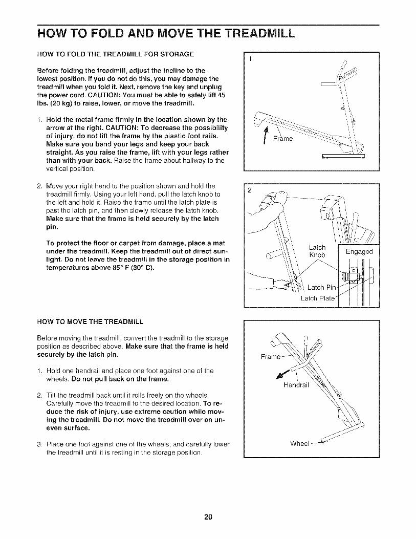
HOW TO FOLD THE TREADMILL FOR STORAGE
Before folding the treadmill, adjust the incline to thelowest position. If you do not do this, you may damage thetreadmill when you fold it. Next, remove the key and unplugthe power cord. CAUTION: You must be able to safely lift 45Ibs. (20 kg) to raise, lower, or move the treadmill.
1. Hold the metal frame firmly in the location shown by thearrow at the right. CAUTION: To decrease the possibilityof injury, do not lift the frame by the plastic foot rails.Make sure you bend your legs and keep your backstraight. As you raise the frame, lift with your legs ratherthan with your back. Raise the frame about halfway to thevertical position.
2. Move your right hand to the position shown and hold thetreadmill firmly. Using your left hand, pull the latch knob tothe left and hold it. Raise the frame until the latch plate ispast the latch pin, and then slowly release the latch knob.Make sure that the frame is held securely by the latchpin.
To protect the floor or carpet from damage, place a matunder the treadmill. Keep the treadmill out of direct sun-light. Do not leave the treadmill in the storage position intemperatures above 85 ° F (30 ° C).
2
rame
Engaged
Latch
HOW TO MOVE THE TREADMILL
Before moving the treadmill, convert the treadmill to the storageposition as described above. Make sure that the frame is heldsecurely by the latch pin.
1. Hold one handrail and place one foot against one of thewheels. Do not pull back on the frame.
2. Tilt the treadmill back until it rolls freely on the wheels.Carefully move the treadmill to the desired location. To re-duce the risk of injury, use extreme caution while mov-ing the treadmill. Do not move the treadmill over an un-even surface.
3. Place one foot against one of the wheels, and carefully lowerthe treadmill until it is resting in the storage position.
Handrail
Wheel
20
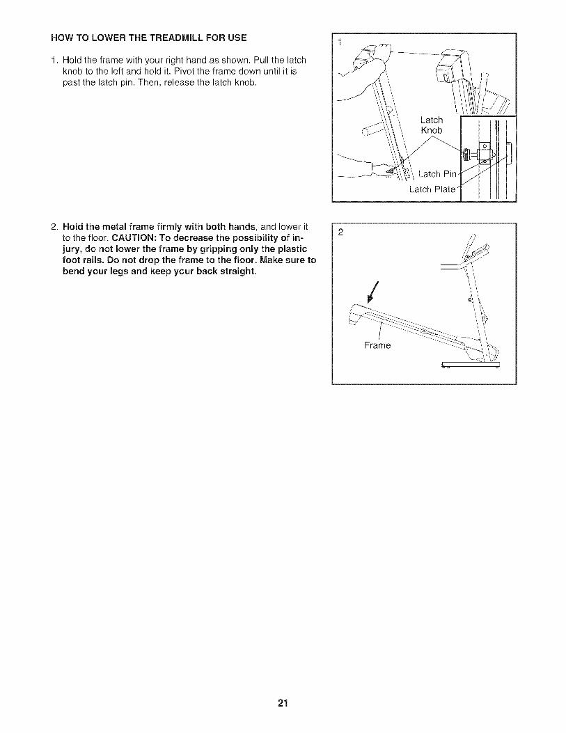
HOW TO LOWER THE TREADMILL FOR USE
1. Hold the frame with your right hand as shown, Pull the latchknob to the left and hold it. Pivot the frame down until it is
past the latch pin. Then, release the latch knob.
Latch Plate
.i
2. Hold the metal frame firmly with both hands, and lower itto the floor. CAUTION: To decrease the possibility of in-jury, do not lower the frame by gripping only the plasticfoot rails. Do not drop the frame to the floor. Make sure tobend your legs and keep your back straight.
/
Frame
21
TROUBLESHOOTING
Most treadmill problems can be solved by following the steps below. Find the symptom that applies, andfollow the steps listed. If further assistance is needed, see the back cover of this manual.
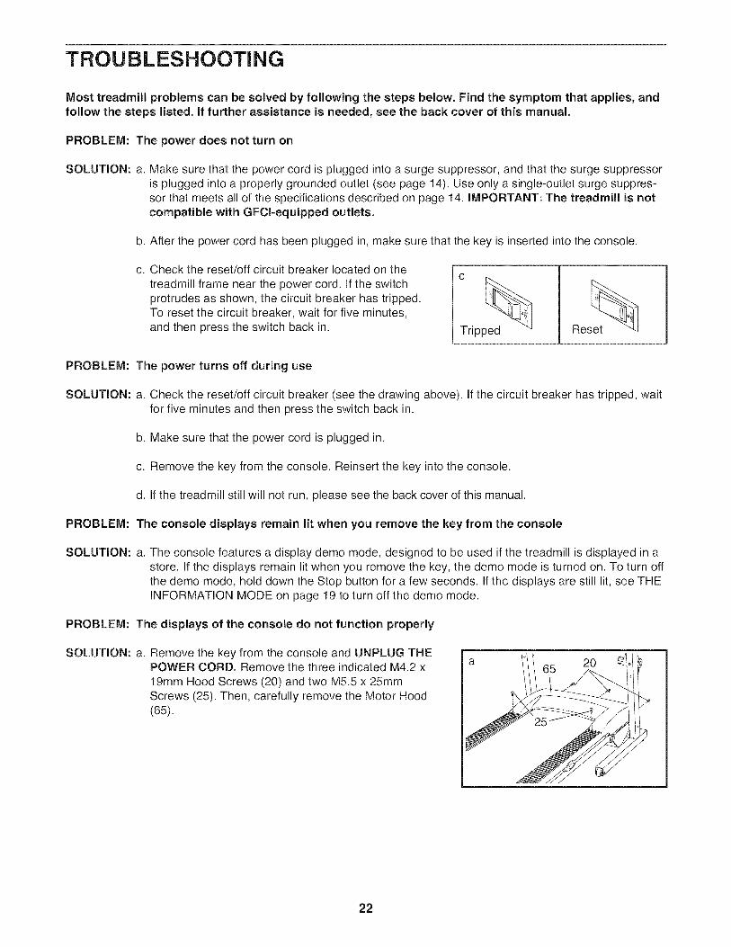
PROBLEM: The power does not turn on
SOLUTION: a. Make sure that the power cord is plugged into a surge suppressor, and that the surge suppressoris plugged into a properly grounded outlet (see page 14). Use only a single-outlet surge suppres-sor that meets all of the specifications described on page 14. IMPORTANT: The treadmill is notcompatible with GFCl-equipped outlets.
b. After the power cord has been plugged in, make sure that the key is inserted into the console.
C. Check the reset/off circuit breaker located on thetreadmill frame near the power cord. If the switchprotrudes as shown, the circuit breaker has tripped.To reset the circuit breaker, wait for five minutes,and then press the switch back in. Tripped Reset
PROBLEM: The power turns off during use
SOLUTION: a. Check the reset/off circuit breaker (see the drawing above). If the circuit breaker has tripped, waitfor five minutes and then press the switch back in.
b. Make sure that the power cord is plugged in.
c. Remove the key from the console. Reinsert the key into the console.
d. If the treadmill still will not run, please see the back cover of this manual.
PROBLEM: The console displays remain lit when you remove the key from the console
SOLUTION: a. The console features a display demo mode, designed to be used if the treadmill is displayed in astore, If the displays remain lit when you remove the key, the demo mode is turned on. To turn offthe demo mode, hold down the Stop button for a few seconds, If the displays are still lit, see THEINFORMATION MODE on page 19 to turn off the demo mode.
PROBLEM: The displays of the console do not function properly
SOLUTION: a. Remove the key from the console and UNPLUG THEaPOWER CORD. Remove the three indicated M4.2 x
19ram Hood Screws (20) and two M5,5 x 25ramScrews (25). Then, carefully remove the Motor Hood(65).
22
PROBLEM:
SOLUTION: a.
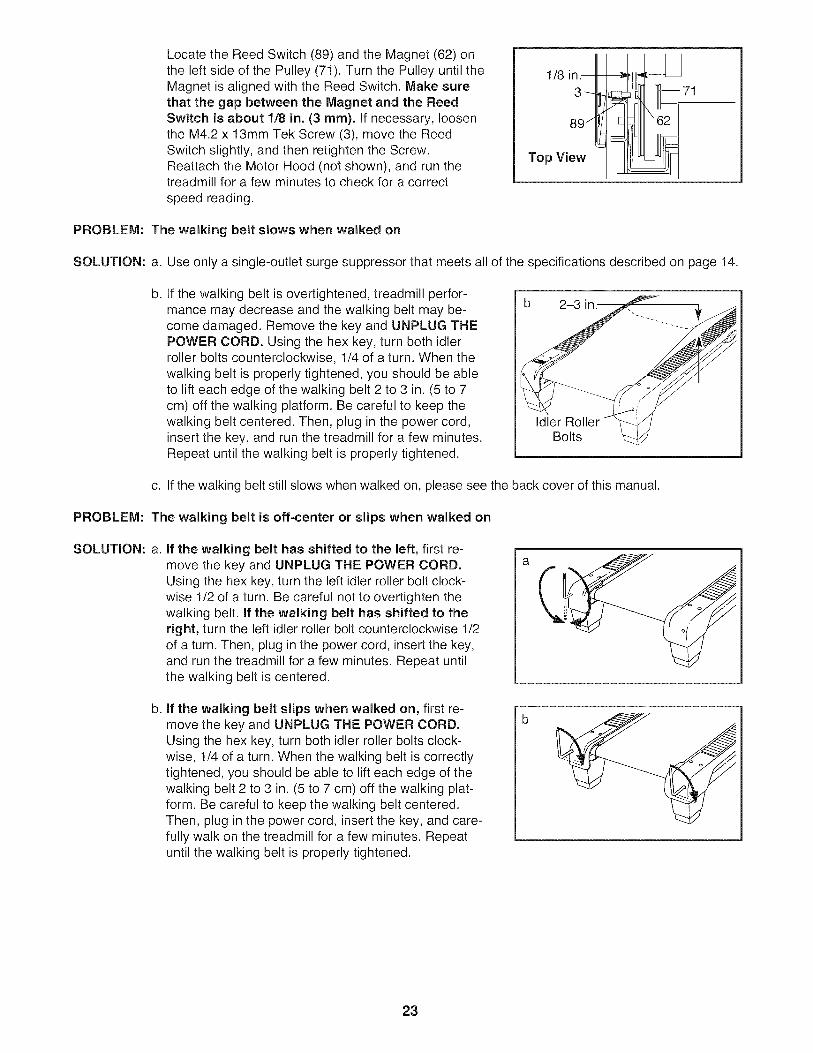
b.
Locate the Reed Switch (89) and the Magnet (62) onthe left side of the Pulley (71). Turn the Pulley until theMagnet is aligned with the Reed Switch. Make surethat the gap between the Magnet and the ReedSwitch is about 1/8 in. (3 mm). if necessary, loosenthe M4.2 x 13ram Tek Screw (3), move the ReedSwitch slightly, and then retighten the Screw,Reattach the Motor Hood (not shown), and run thetreadmill for a few minutes to check for a correct
speed reading.
1/8 in3- _71
Top View
The walking belt slows when walked on
Use only a single-outlet surge suppressor that meets all of the specifications described on page 14.
If the walking belt is overtightened, treadmill perfor-mance may decrease and the walking belt may be-come damaged. Remove the key and UNPLUG THEPOWER CORD. Using the hex key, turn both idlerroller bolts counterclockwise, 1/4 of a turn. When thewalking belt is properly tightened, you should be ableto lift each edge of the walking belt 2 to 3 in. (5 to 7cm) off the walking platform. Be careful to keep thewalking belt centered. Then, plug in the power cord,insert the key, and run the treadmill for a few minutes.Repeat until the walking belt is properly tightened.
b 2-3
Idler RollerBolts
c. If the walking belt still slows when walked on, please see the back cover of this manual.
PROBLEM:
SOLUTION: a.
The walking belt is off-center or slips when walked on
b.
if the walking belt has shifted to the left, first re-move the key and UNPLUG THE POWER CORD.Using the hex key, turn the left idler roller bolt clock-wise 1/2 of a turn. Be careful not to overtighten thewalking belt. if the walking belt has shifted to theright, turn the left idler roller bolt counterclockwise 1/2of a turn. Then, plug in the power cord, insert the key,and run the treadmill for a few minutes. Repeat untilthe walking belt is centered.
if the walking belt slips when walked on, first re-move the key and UNPLUG THE POWER CORD.Using the hex key, turn both idler roller bolts clock-wise, 1/4 of a turn. When the walking belt is correctlytightened, you should be able to lift each edge of thewalking belt 2 to 3 in. (5 to 7 cm) off the walking plat-form. Be careful to keep the walking belt centered.Then, plug in the power cord, insert the key, and care-fully walk on the treadmill for a few minutes. Repeatuntil the walking belt is properly tightened.
23

PROBLEM: The crosswalk arms squeak during use
SOLUTION: a. (Note: Correcting this problem requires a smallamount of white marine grease, available at hard-ware stores.) Turn the Resistance Knob (A) coun-terclockwise and remove it. Next, remove theResistance Cone (B) and the Left Crosswalk Arm(73), along with the Resistance Plate (C), Washers(D), Spring Washer (E), Thrust Washers (F), andThrust Bearing (G). (Note: If the Resistance Plate[C] comes out of the Resistance Cone [B], press itback in.) Apply a thin layer of white marine greaseto the outer surface of the Resistance Cone (B).Then, reattach all parts in the order shown at theright.
©
CG
D
A
PROBLEM: The incline of the treadmill does not change correctly
SOLUTION: a. With the key in the console, press one of the Incline buttons. While the incline is changing, re-move the key. After a few seconds, re-insert the key. The treadmill will automatically rise to themaximum incline level and then return to the minimum level. This will recalibrate the incline system.
24
EXERCISE GUiDELiNES
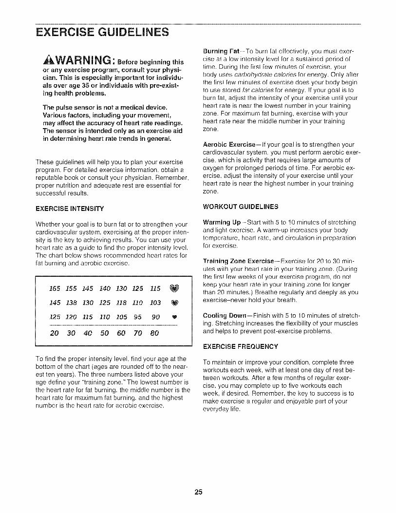
: Beforebeginningthisor any exercise program, consult your physi=cian. This is especially important for individu-als over age 35 or individuals with pre-exist-ing health problems.
The pulse sensor is not a medical device.Various factors, including your movement,may affect the accuracy of heart rate readings.The sensor is intended only as an exercise aidin determining heart rate trends in general.
These guidelines will help you to plan your exerciseprogram. For detailed exercise information, obtain areputable book or consult your physician. Remember,proper nutrition and adequate rest are essential forsuccessful results.
EXERCISE INTENSITY
Whether your goal is to burn fat or to strengthen yourcardiovascular system, exercising at the proper inten-sity is the key to achieving results. You can use yourheart rate as a guide to find the proper intensity level.The chart below shows recommended heart rates for
fat burning and aerobic exercise.
]65 155 145 140 130 I25 115 _
I45 138 130 125 118 110 103 _W)
i25 120 115 110 I05 95 90 W
20 30 40 50 60 70 80
To find the proper intensity level, find your age at thebottom of the chart (ages are rounded off to the near-est ten years). The three numbers listed above yourage define your "training zone." The lowest number isthe heart rate for fat burning, the middle number is theheart rate for maximum fat burning, and the highestnumber is the heart rate for aerobic exercise.
Burning Fat--To burn fat effectively, you must exer-cise at a low intensity level for a sustained period oftime. During the first few minutes of exercise, yourbody uses carbohydrate calories for energy. Only afterthe first few minutes of exercise does your body beginto use stored fat calories for energy, if your goal is toburn fat, adjust the intensity of your exercise until yourheart rate is near the lowest number in your trainingzone. For maximum fat burning, exercise with yourheart rate near the middle number in your trainingzone.
Aerobic Exercise--if your goal is to strengthen yourcardiovascular system, you must perform aerobic exer-cise, which is activity that requires large amounts ofoxygen for prolonged periods of time. For aerobic ex-ercise, adjust the intensity of your exercise until yourheart rate is near the highest number in your trainingzone.
WORKOUT GUIDELINES
Warming Up--Start with 5 to 10 minutes of stretchingand light exercise. A warm-up increases your bodytemperature, heart rate, and circulation in preparationfor exercise.
Training Zone Exercise--Exercise for 20 to 30 min-utes with your heart rate in your training zone. (Duringthe first few weeks of your exercise program, do notkeep your heart rate in your training zone for longerthan 20 minutes.) Breathe regularly and deeply as youexercise-never hold your breath.
Cooling Down--Finish with 5 to 10 minutes of stretch-ing. Stretching increases the flexibility of your musclesand helps to prevent post-exercise problems.
EXERCISE FREQUENCY
To maintain or improve your condition, complete threeworkouts each week, with at least one day of rest be-tween workouts. After a few months of regular exer-cise, you may complete up to five workouts eachweek, if desired. Remember, the key to success is tomake exercise a regular and enjoyable part of youreveryday life.
25

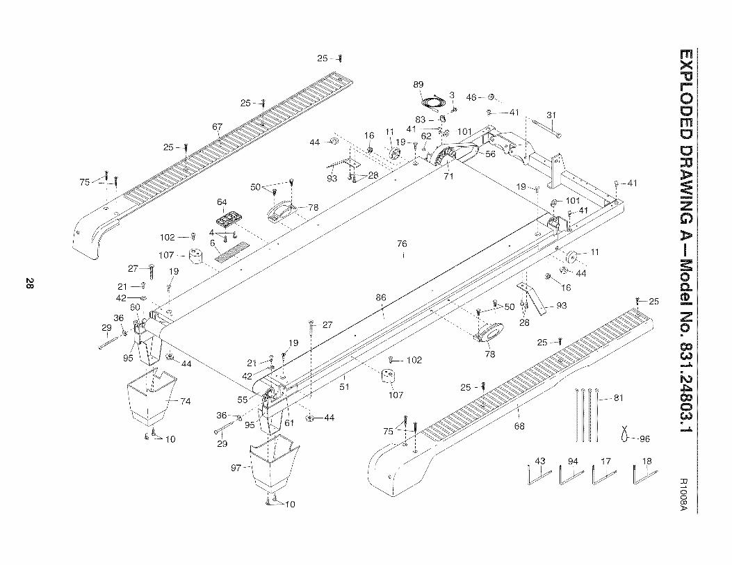
PART LISTmModel No. 831.24803.1 RlOOSA
To locate the parts listed below, see the EXPLODED DRAWING near the end of this manual.
Key No. Qty. Description Key No. Qty. Description
1 2 M10 x 60mm Patch Bolt 51 12 6 M10 x 58mm Bolt 52 13 2 M4,2 x 13mm Tek Screw 53 14 6 M4,2 x 16mm Screw 54 15 4 M8 Star Washer 55 16 1 Latch Warning Decal 56 17 2 M5 Star Washer 57 18 4 M8 x 15mm Bolt 58 19 6 M10 Star Washer 59 110 12 M4.2 x 19mm Screw 60 111 4 Frame Spacer 61 112 1 Console Back 62 113 2 Crosswalk Arm Insert 63 414 2 M10 Flat Washer 64 115 1 Key/Clip 65 116 4 M10 Nut 66 117 1 6 mm Hex Key 67 118 1 4 mm Hex Key 68 119 4 M8 x 30mm Screw 69 420 3 M4,2 x 19mm Hood Screw 70 221 6 M4,2 x 13mm Screw 71 122 1 Left Handrail 72 123 1 Lift Frame 73 124 1 Latch Pin Assembly 74 125 6 M5,5 x 25mm Screw 75 426 4 M4,2 x 19mm Tek Screw 76 127 2 M8 x 35mm Screw 77 428 4 M4,2 x 13mm Belt Guide Screw 78 229 2 Idler Roller Adjustment Bolt 79 130 2 1/4" Motor Bolt 80 231 1 M8 x 102mm Bolt 81 1232 4 1/4" Flat Washer 82 133 1 Right Handrail 83 134 2 M8 x 20mm Bolt 84 235 2 M10 x 60mm Bolt 85 236 2 M6 Star Washer 86 137 1 Reset/Off Circuit Breaker 87 138 2 M8,4 Star Washer 88 139 1 Wire Harness 89 140 1 Incline Motor 90 141 4 M 4,2 x 13mm Belly Pan Screw 91 142 4 M 4,2mm Star Washer 92 143 1 Hex Key 93 244 6 M8 Flange Nut 94 145 2 Hand Grip 95 246 1 M8 Jam Nut 96 147 3 Hood Clip 97 148 1 Latch Housing 98 149 2 Grommet 99 150 4 Isolator Fastener 100 1
FrameBaseLeft UprightRight UprightIdler RollerDrive Motor BeltElectronics Bracket3/8" x 1 3/4" BoltMotor BracketLeft Idler Roller BracketRight Idler Roller BracketMagnetBase FootLatch PlateMotor HoodBelly PanLeft Foot RailRight Foot RailWheel SpacerWheelDrive Roller/Pulley3/8" x 1 1/4" BoltLeft Crosswalk ArmRear Foot, LeftM5,5 x 30mm ScrewWalking BeltHandrail CapPlatform CushionDrive MotorWire Tie8" Tie3/8" LocknutReed Switch ClampM4 x 10mm Ground ScrewM5 x 16mm ScrewWalking PlatformControllerConsole CrossbarReed SwitchPower CordConsole Assembly3/8" Jam NutBelt Guide5mm Hex KeyFrame CapReleasable TieRear Foot, RightFilter WirePower Cord GrommetIncline Motor Wire
26

Key No. Qty. Description Key No. Qty. Description
101 2 Front Roller Washer 110 2 #10 x 3/4" Screw102 3 M4.2 x 18mm Screw 111 4 1/4" x 3" Bolt103 1 Right Crosswalk Arm 112 2 #10 x 1" Tek Screw104 2 Base Cap * - 6" Red Wire, M/F105 4 Cage Nut * - 8" Black Wire, M/F106 2 Caution Decal * - 4" Blue Wire, 2F107 2 Isolator * - 4" Black Wire, M/F108 2 M4 x 10ram Controller Screw * - 10" White Wire, M/F109 2 Resistance Assembly * - User's Manual
Note: Specifications are subject to change without notice, See the back cover of this manual for information aboutordering replacement parts. If a part is missing, call 1-888-533-1333. *These parts are not illustrated.
27
oo
29
95
67
64
29
21
41
76
86
19
10
89
83
46 --@..
25
68
31
16
43 94 17
81
mX
/..,,0
m
m
Z63
I
0
m
Z0!
60
i,o4_
Qt,,,O!
33
ooo0>
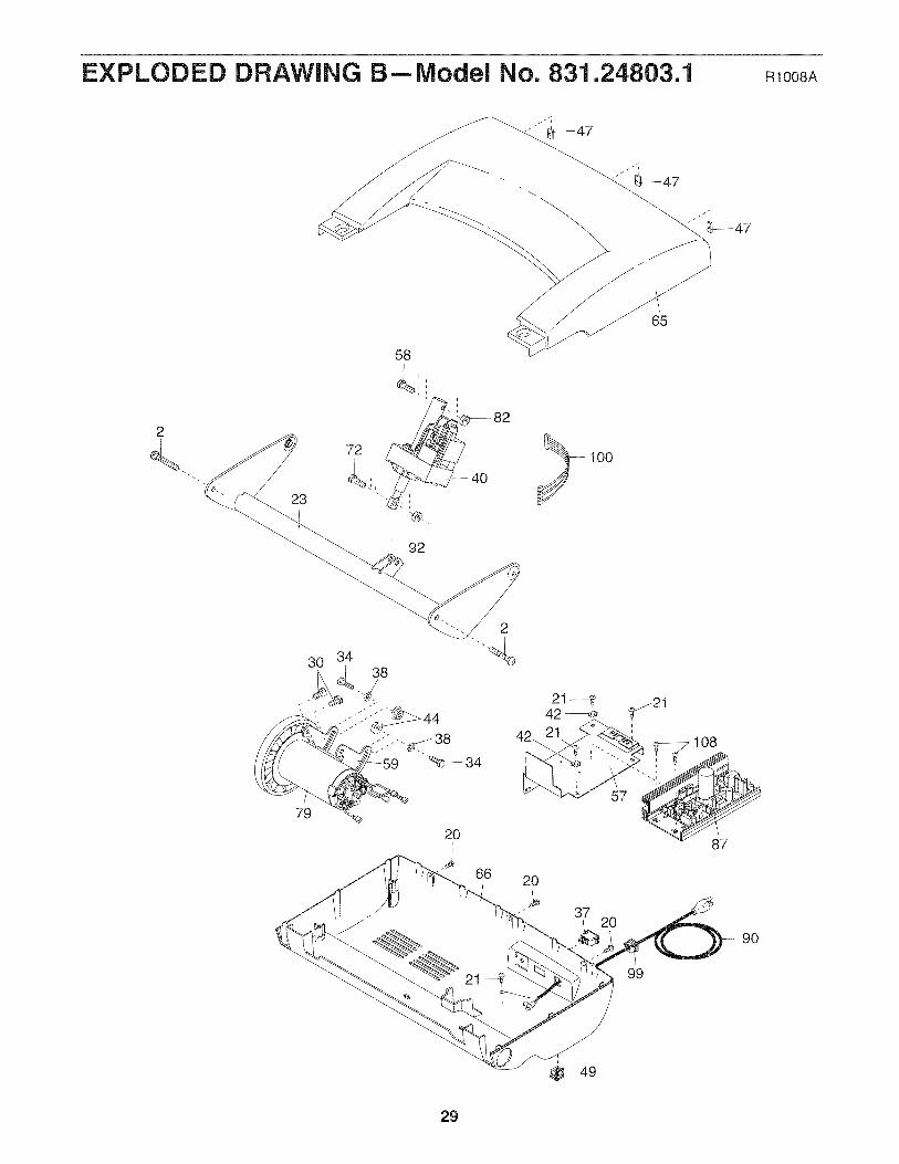
EXPLODED DRAWING BmModel No. 831.24803.1 RlOO8A
92
100
65
30 3438
2
79
"%_-- 34
20
66 20
37
57
108
87
2090
99
29
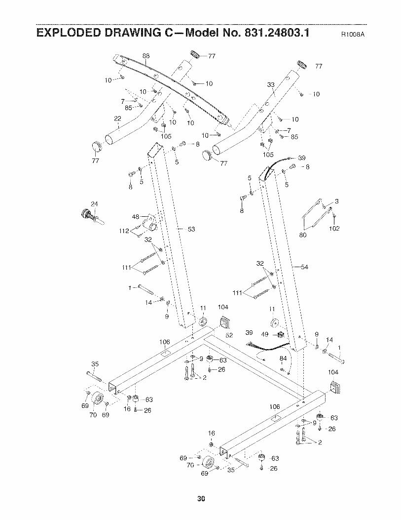
EXPLODED DRAWING CmModel No. 831.24803.1 Rloo8A
88 _ 77
22
77
24
10 10
105 10_
5 77
8
5
80102
1132
11 104 11
35
69
70
106
16
69 -_.70
69
84
106
914
1
104
30

EXPLODED DRAWING DmlVlodel No. 831.24803.1 Rloo8A
15
91
12
4---_
103
45
110
_109 13
31

Your Home
iiiiiiiiiiiiiiiiiil
iiiiiiiiiiiiiiiiiiiiiiiiiiiiiiiiiiiiiiiiiiiiiiiiiiiiiiiiiiiiiiiiiiiiiiiiiiiiiiiiiiiiiiiiiiiiiiiiiiiiiiiiiiiiiiiii_iiiiiiiiiiiiiiiiiii
_iiiiiiiiiiiiiiiiiiiiiiiiiiiiiiiiiiiiiiiiiiiiiiiiiiii!i_!_!i_
For repair--in your home--of all major brand appliances, lawn and garden equipment,or heating and cooling systems, no matter who made it, no matter who sold it!
For the replacement parts, accessories, and user's manuals that you need to do-it-yourself.
For Sears professional installation of home appliances
and items like garage door openers and water heaters.
1-800-4-MY-HOME ® (1-800-469-4663)
Call anytime, day or night (U.S.A. and Canada)
www.sears.co., www.sears.ca
Our Home
For repair of carry-in items like vacuums, lawn equipment,and electronics, call or go on-line for the location of your nearest
Sears Parts & Repair Center.
1"800"488"1222 Call anytime, day or night (U.S.A. only)
www.sears.co.,
To purchase a protection agreement (U.S.A.)or maintenance agreement (Canada)on a product serviced by Sears:
1-800-827-6655 (U.S.A.) 1-800-361-6665 (Canada)
Pard pedir servicio de reparacion a domicilio, y pard ordenar piezas:
1-888-SU-HOGAR ®(1-888-784-6427)
® Registered Trademark / TMTrademark / SMService Mark of Sears Brands, LLC
® Marca Registrada / TMMarca de F&brica / sMMarca de Servicio de Sears Brands, LLC
f
90 DAY FULL WARRANTY
If this Sears Treadmill Exerciser fails due to a defect in material or workmanship within 90 days of thedate of purchase, call 1-800-4-MY-HOME ® (1-800-469-4663) to arrange for free repair (or replacement ifrepair proves impossible). The drive motor is warranted for 5 years from the date of purchase.
This warranty does not apply when the Treadmill Exerciser is used commercially or for rental purposes.
This warranty gives you specific legal rights, and you may also have other rights which vary from state tostate.
Sears, Roebuck and Co., Hoffman Estates, IL 60179
J
,J
Part No. 276201 R1008A Printed in China © 2008 ICON IP, Inc.