tp 224 c - hendrickson asia pacific - hendrickson asia pacific
TRANSCRIPT

HA/HAS Series
��������
ITEM SUBJECT PAGE
1 Introduction “EDGE” ........................................................................ 2
2 Important Safety Notice .................................................................... 3
3 Frame Slope .................................................................................... 4
4 Axle/Suspension Angle Inspection ...................................................... 5
5 Driveline Inspection .......................................................................... 7
6 Setting Ride Height ........................................................................... 9
7 HI-Torque Shock Absorber ............................................................... 10
8 Air Plumbing Diagram .................................................................... 11
9 Tightening Torque Specification Chart ............................................... 12
NO: 17730-224SUBJECT: Driveline Angularity ProceduresDATE: March, 1999 REVISION: C
TECHNICALPUBLICATION17730-224
2®
Subject 1INTRODUCTION EDGE
This publication is to acquaint and assist fleets, end users and maintenance personnelto appropriately set up and maintain universal joint angularity with Hendrickson HASSeries suspensions. Technical publications associated with this publication are17730-197, 17730-212, 17730-222.
In the commercial trucking industry, drive train vibration is a major issue. Pinionangles and suspension ride height can cause undesirable noise and vibration issuesas well as premature driveline component failures when not properly set. The onlyaffect that the suspension has on the driveline is setting the seat angles as developedby the OEM. The suspension does not effect other vibration problems such as; engineexcited torsionals, driveline system resonance, rotating imbalance, drive shaft runoutand bearing looseness. Hendrickson has developed a system approach to accuratelycontrol driveline angularity. This system promotes Efficient Driveline GEometry (EDGE).The EDGE design features include.
■ Hi-Torque shock absorbers.■ Optimal height control system.■ Education for optimizing vehicle set up.
For acceptable reductions in U-joint vibration all three features listed above mustbe applied.
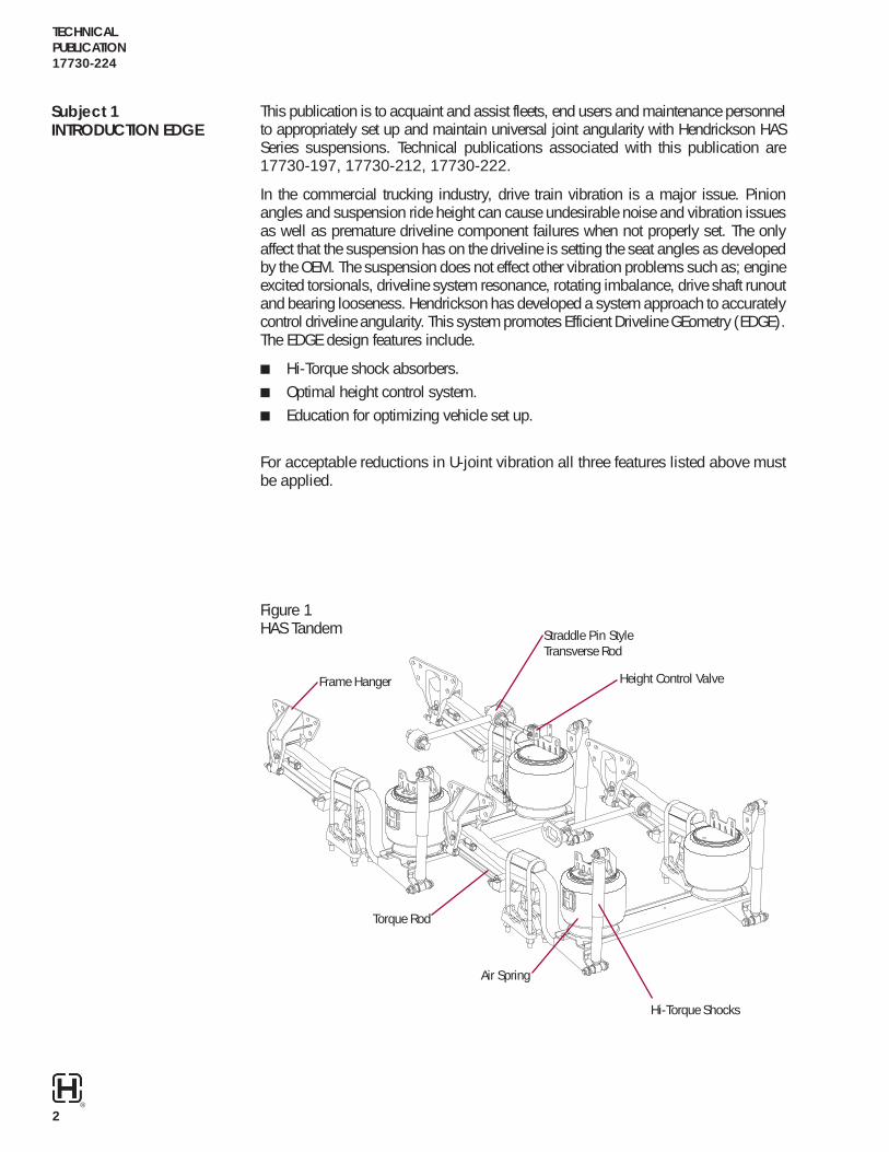
Figure 1HAS Tandem Straddle Pin Style
Transverse Rod
Height Control ValveFrame Hanger
Torque Rod
Air Spring
Hi-Torque Shocks

TECHNICALPUBLICATION
17730-224
3®
Proper service and repair is important to the safe and reliable operation of the tandemsuspension. The service procedures recommended by Hendrickson and described inthis technical publication are effective methods of performing maintenance.
There are various warnings and cautions that should be read carefully to minimize therisk of personal injury and to assure that proper methods are used. Improper servicingmay damage the vehicle or render it unsafe in operation.
HENDRICKSON SUSPENSION REMINDS USERS TO ADHERE TO THE PUBLISHEDCAPACITY RATINGS FOR THE SUSPENSIONS.
ADD-ON AXLE ATTACHMENTS AND OTHER LOAD TRANSFERRING DEVICESCAN INCREASE THE SUSPENSION LOAD ABOVE THE RATED AND APPROVEDCAPACITIES WHICH COULD RESULT IN FAILURE OF THE SUSPENSION ANDLOSS OF VEHICLE CONTROL, POSSIBLY CAUSING PERSONAL INJURY ORPROPERTY DAMAGE.
DUMP TRUCK APPLICATIONS — WHEN THE BED OF THE TRUCK IS LIFTED IT ISMANDATORY TO COMPLETELY EXHAUST THE AIR FROM THE SUSPENSION SYSTEMTO PROVIDE STABILITY ON AN UNEVEN TERRAIN. FAILURE TO DO SO COULDRESULT IN LOSS OF VEHICLE CONTROL, POSSIBLY CAUSING PERSONAL INJURYOR PROPERTY DAMAGE.
DO NOT MODIFY OR REWORK PARTS. DO NOT USE SUBSTITUTE PARTS. USE OFA MODIFIED OR SUBSTITUTE PART IS NOT RECOMMENDED BECAUSE THE PARTMAY NOT MEET HENDRICKSON'S SPECIFICATIONS, WHICH COULD RESULT INFAILURE OF THE PART, LOSS OF VEHICLE CONTROL, AND POSSIBLE PERSONALINJURY OR PROPERTY DAMAGE.
DO NOT USE A CUTTING TORCH TO REMOVE ANY ATTACHING FASTENERS. THEUSE OF HEAT ON SUSPENSION COMPONENTS WILL ADVERSELY AFFECT THESTRENGTH OF THESE PARTS. A COMPONENT DAMAGED IN THIS MANNER MAYRESULT IN THE LOSS OF VEHICLE CONTROL AND POSSIBLE PERSONAL INJURYOR PROPERTY DAMAGE.
EXERCISE EXTREME CARE WHEN HANDLING OR PERFORMING MAINTENANCEIN THE AREA OF THE MAIN SUPPORT MEMBERS. DO NOT CONNECT ARCWELDING GROUND LINE TO THE MAIN SUPPORT MEMBERS. DO NOT STRIKEAN ARC WITH THE ELECTRODE ON THE MAIN SUPPORT MEMBERS. DO NOTUSE HEAT NEAR THE MAIN SUPPORT MEMBERS. DO NOT NICK OR GOUGE THEMAIN SUPPORT MEMBERS. A MAIN SUPPORT MEMBER THAT HAS BEENSUBJECTED TO ANY OF THESE CONDITIONS MAY FAIL, CAUSING LOSS OFVEHICLE CONTROL AND POSSIBLE PERSONAL INJURY OR PROPERTY DAMAGE.
A MECHANIC USING A SERVICE PROCEDURE OR TOOL WHICH HAS NOT BEENRECOMMENDED BY HENDRICKSON MUST FIRST SATISFY HIMSELF THAT NEITHERHIS SAFETY NOR THE VEHICLE’S SAFETY WILL BE JEOPARDIZED BY THE METHODOR TOOL SELECTED. INDIVIDUALS DEVIATING IN ANY MANNER FROM THEINSTRUCTIONS PROVIDED ASSUME ALL RISKS OF CONSEQUENTIAL PERSONALINJURY OR DAMAGE TO EQUIPMENT INVOLVED.
Subject 2IMPORTANT SAFETY NOTICE
�����������

TECHNICALPUBLICATION17730-224
4®
Figure 2Ride Height Loaded
Bottom of Main Support Member
Bottom of Frame
�
�
Main SupportMember Part No. Location
= 4¼" Loaded Height43/8" Unloaded Height
Drive axle pinion angles are established by the vehicle manufacturer. The suspensionspring seats called out in Hendrickson Technical Publications 17730-197, 17730-212and 17730-222 are cast and machined to specific angles to meet the vehicle manu-facturer specified requirements. Because the main support members deflect slightlyunder a full load, empty chassis axle angles measure about one degree less thanwhen the vehicle is fully loaded.
In most cases, the original vehicle manufacturer installs spring seats that are equalthickness on both the forward drive and the rear drive axles. These equal thicknessspring seats are designed to have frames parallel to the ground which results in 0°frame slope. The intent is to maintain identical (4¼" loaded and 43/8" unloaded)main support member heights on the forward drive axle and the rear drive axle asshown in Figure 2. Maintaining these identical heights assures equal loading on bothdrive axles as well as correct axle pinion angles. Chassis frame slope in excess ofone degree may cause unequal loading between the two drive axles which may bedetrimental to vehicle ride. If this condition persists contact the vehicle manufacturerfor guidelines or proceed with the following recommendations:
Subject 3����������
1. If the frame slopes downward and toward the cab the front drive axle will, in allprobability, weigh more than the rear drive axle.
2. If the frame slopes upward towards the cab the rear drive axle will be the heavierof the two.
3. If the frame height at the tandem suspension is too low, it could be corrected byadding spacer plates to all four corners of the tandem drive axles between themain support members and the spring seats. Do not attempt to correct frameslope by adding spacer plates on only one drive axle. The spacer plates can bemade from ½" x 3" x 7" low carbon steel with a 13/16" dia. hole drilled in the centerfor dowel clearance. A maximum of two ½" shop made spacer plates betweeneach main support member and spring seat is permissible. Longer U bolts will berequired to accommodate spacer plates. Hendrickson has 1" and 1½" thick spac-ers available as production items. A maximum of one 1" thick, or one 1½" thickspacer is permissible.

TECHNICALPUBLICATION
17730-224
5®
Figure 3HendricksonHeight Gauge
Height Gauge
Top Pad
Frame
U Bolt
Main SupportMember
Spring Seat Spacer
4. If frame slope is excessive (greater than what can be corrected for with a 1½"spacer) it should be corrected by the vehicle manufacturer.
5. If the frame height at the tandem suspension is too high, the spacers can beremoved (if so equipped), or the front steer axle suspension can be raised.
6. Do not make changes to the steering axle without prior approval and supervi-sion of the O.E.M. as the steering geometry could be affected thus, causingsteering problems.
Subject 4AXLE/ SUSPENSION ANGLEINSPECTION
The following inspection procedure is recommended when axle angle adjustment isrequired for the rear tandem axle using the HAS series suspension.
Inspections can be performed on an unloaded vehicle. Inspections on a loaded ve-hicle can be difficult to schedule.
1. Free and center all suspension joints by slowly moving vehicle back and forthseveral times without using the brakes. When coming to a complete stop makesure the brakes are released. Chock front wheels.
2. Verify that the front steer and rear drive tires are inflated to normal operating pressure.3. Using a Hendrickson height gauge, see Figure 3, (part number Loaded
45745-050, Unloaded 45745-106), measure the suspension height on theforward and rear drive axles, as shown is Figures 2 and 3. If the vehicle isequipped with equal thickness spring seats and the frame is level, all four mainsupport members should have the same loaded suspension height of 4.25" ± .12"or 4.38" ± .12" unloaded. Again, this measurement is from the bottom of theframe to the bottom of the main support member (spring) as shown in Figure 2.

TECHNICALPUBLICATION17730-224
6®
Figure 4
Positive
Negative
Z
Y
X
4. If the frame slopes toward the cab, (positive (+) frame slope) the front driveapproval axle angle will be less compared to the vehicle manufacturer specifiedangle. If the frame slopes away from the cab (negative (-) frame slope) the frontdrive axle angle will be higher than the vehicle manufacturer specified angle. Theframe slope on empty vehicles equipped with equal thickness spring seat mustbe ± 0.8º.
5. To correct frame slope, spacer plates can be added or removed on all four cor-ners of both drive axles between the main support, as shown in Figure 5, or byadding spacer(s) to the front steer axle. If spacer plates are added, longer U-boltswill be required to accommodate the added spacer plates. Hendrickson has 1"thick spacers (part number 48902-000) and 1½" thick spacers (part number48903-000) available as production items. A maximum of one 1" thick, or one1½" thick spacer is permissible. Do not make changes to the steering axle with-out prior approval and supervision of the O.E.M. as the steering geometry couldbe affected.
6. Record the measurements obtained from step 3 in the appropriate spaces pro-vided on the Inspection Form (See Page 8).
4.25" ± .12" = Suspension Ride Height on Forward Axle
X ± Y< 2° = Minimum Cancellation ErrorX or Y < 6° = Maximum Working Angle
Z < ± .2° = Loaded ConditionZ < ± .8° = Unloaded Condition
If a Hendrickson height control valve assembly (part number 57977-000) is installedon the rear drive axle, the ride height setting, as shown in Figure 3 should still bemeasured at the forward drive axle.
����
Subject 4AXLE/ SUSPENSION ANGLEINSPECTION (Cont.)

TECHNICALPUBLICATION
17730-224
7®
Joint working angles should not exceed 6°Cancellation error should not exceed 2°
A4
J4
A5
J5
A6
4˚ 3˚
Subject 5DRIVELINE INSPECTION
1. To measure driveline angles, the vehicle must be placed on a level floor.2. Inspections can be performed on either loaded or unloaded vehicles.3. The front steer and rear drive tires
must be inflated to normal operatingpressure.
4. Free and center all suspension jointsby slowly moving vehicle back andforth several times without using thebrakes. When coming to a completestop make sure the brakes are re-leased Chock the front wheels.
5. Using Figure 5 as a guide to deter-mine the angles to be measured anda digital inclinometer as the measur-ing tool, measure the driveline anglesand record them in the appropriatespaces on the Inspection Form (SeePage 8). Figure 5 shows the propermethod for using the inclinometer.
6. Using the driveline angles A4, A5,and A6 that were recorded in theDriveline Inspection Form and cal-culate the interaxle cancellation. Thedifference between the joint working angles (JWA) is the recorded result.
7. Hendrickson’s specification for good interaxle cancellation is <2º and joint work-ing angles (JWA) <6º as shown Figure 6.
Figure 5Measurement of Axle Angles (A4 + A5)
Forward Axle (A4 = 2.5°) I.A.S. (A5 = 6.5°) Rear Rear Axle (A6 = 9.5°)
(“JWA” J4 =�A5 - A4� = 4°) (“JWA” J5 = �A5 – A6� = 3°)
Cancellation Error =�J4 - J5�= 1°
Figure 6
����������� The change in axle wind-up is less severe on the forward axle output (J4) then therear axle input (J5). Optimum results occur when J4 is less then J5.

TECHNICALPUBLICATION17730-224
8®
DRIVELINE INSPECTION FORM
Vehicle Information
Vehicle Owner ____________________________________ Wheel Base ________________________________
Vehicle Make ______________________________________________ Drive Axle ________________________
Model ________________________________Tandem Suspension/Kit No. _____________________________
VIN __________________________________ Tandem Spread _______________________________________
Build Date _____________________________ Mileage ____________________________________________
By ___________________________________ Engine H.P./Torque ____________________________________
Date _________________________________ Transmission Model/Speed ______________________________
Data Collection
Frame Slope ___________________________ Frame Height Front ____________________________________
Forward Drive Axle Height _________________ Frame Height Center ___________________________________
Rear Drive Axle Height ____________________Frame Height Rear_____________________________________
Engine/Trans Angle A1 =_______________
1st Drive Shaft Angle A2 =_______________ J1 = �A1-A2�= _________
Coupling Shaft Angle A3 =_______________ J2 = �A2-A3�= _________ C = �J1-J3�= ___________
Forward Drive Axle Angle A4 =_______________ J3 = �A3-A4�= _________ C = �J1-J3�= ___________
Inter-Axle Shaft Angle A5 =_______________ J4 = �A4-A5�= _________
Rear Drive Axle Angle A6 =_______________ J5 = �A5-A6�= _________ C = �J4-J5� = __________
A = Angle J = Joint Angle C = Cancellation Angle

TECHNICALPUBLICATION
17730-224
9®
Figure 7Height Control ValvePart No. 57977-000
1. The front steer and rear drive tires must be inflated to normal operating pressure.2. Free and center all suspension joints by slowly moving vehicle back and forth
several times without using the brakes. When coming to a complete stop makesure the brakes are released Chock the front wheels.
3. Remove upper fasteners from the linkage located at the rubber grommet and freeleveling arm. See Figure 7.
4. Dump air from suspension system.5. Refill suspension system air.6. Measure (4¼" loaded or 43/8" unloaded) on the forward axle.7. Center the locator on lever arm as shown in Figure 7.8. Adjustment of the ride height control valve linkage can be achieved by loosening
the clamp at the bottom of the extension rod and repositioning the valve arm jointvertically on the extension rod, as shown in Figure 7.
9. All four main support members should have the same height (loaded 4¼" or43/8") unloaded as shown in Figure 2. A Hendrickson height gauge, (part num-ber Loaded 45745-050, Unloaded 45745-106) is available from Hendricksonto simplify establishing the 4¼" or 43/8" dimension as shown in Figure 3.
10. Attach upper fasteners, tightening torque 100-150 in. lbs. Tighten lower valvearm clamp until securely fastened.
���� During cycle operation of the height control valve it is normal to experience a limitedamount of exhaust noise.
Subject 6SETTING RIDE HEIGHT
Center Locator
Extension Rod
5/16" LocknutTightening Torque100-150 in. lbs.
RubberGrommet
Valve ArmClamp
AdjustableValve Arm
Leveling Arm

TECHNICALPUBLICATION17730-224
10®
1. Frame rise, as shown in Figure 8, is caused by axle wheel torque input. This canbe reduced by installing the Hendrickson Hi-Torque shock part number 57905-001as shown in Figure 9.
HI-TORQUESHOCK ABSORBER
EXTENDED
RIDE HEIGHTCOMPRESSED
Figure 9
Figure 8Frame Rise
Subject 7HI-TORQUE SHOCKABSORBER
FRAME RISE

TECHNICALPUBLICATION
17730-224
11®
Height Control Valve Part No. 57977-000I/E – Intake/ExhaustC1 – Delivery to Air Spring (Left Side)C2 – Delivery to Air Spring (Right Side)
Plumbing With NEW Height Control ValveThe new height control valve eliminates the need for a separate quick releasedump valve (1996-Present).
Subject 8HAS AIR PLUMBINGDIAGRAM
³/8" Air LineS.A.E., D.O.T.Approved
EDGEEFFICIENT
DRIVELINE
GEOMETRY
¼" Air LineS.A.E., D.O.T.Approved

TECHNICALPUBLICATION
17730-224
The Boler Company.Copyright © 1999
All Rights Reserved.No. 17730-224C 5M-3-99 Printed in the United States of America
Truck Suspension Systems 630.910.2800800 South Frontage Road Fax 630.910.2899Woodridge, Illinois 60517-4904 USA www.hendrickson-intl.com
noitpircseD .oNtraPnoskcirdneHedarG/daerhT
euqroT.sbL/.tF
emarFelciheVotregnaHgnirpSsrehsaW&,stuN,stloB enoN ybdellatsnI&dehsinruF
rerutcafunaMkcurT *
tunkcoLtloBU 000-56705 CedarGB2-FNU41-"8/7 054-004
tunkcoLniPraBdoReuqroT 000-46774 CedarGB2-CNU11-"8/5 502-051
dutStaeSgnirpS 000-81905 8edarGA2-CNU11-"8/5 07-06
tunkcoLtloBdnuobeR 000-64894 CedarGB2-CNU31"2/1 07-05
reppU/tunkcoLrebrosbAkcohS 000-64894 CedarGB2-CNU31-"2/1 07-05
rewoL/tunkcoLrebrosbAkcohS 000-24894 CedarGB2-CNU01-"4/3 07-05
tunkcoLMSMotlennahCssorC 000-24894 CedarGB2-CNU01-"4/3 023-062
otgnirpSriAtunkcoLregnaHemarF 010-00771 5edarGB2-CNU31-"2/1 03-02
otgnirpSriAtunkcoLlennahCssorC 010-00771 5edarGB2-CNU31-"2/1 03-02
tunkcoLdoResrevsnarT 000-94792 5edarGB3-FNU21-"4/11 522-571
tuNmaJmrAnoisnetxE 910-19471 5edarGB2-FNU42-"61/5 .SBL/NI051-001
tunkcoLmrAnoisnetxE 000-84984 CedarGB2-FNU42-"61/5 .SBL/NI051-001
pmalCmrAevlaV 000-96985 yleruceSdenetsaF
Subject 9TIGHTENING TORQUESPECIFICATION CHART
������������� *Torque values listed above apply only if Hendrickson supplied fasteners are used. Ifnon-Hendrickson fasteners are used, follow torque specifications listed in vehiclemanufacturer’s service manual.
All threads must be clean and lubricated with SAE 20 oil before assembly to obtainthe correct relationship of torque and fastener tension.
To obtain maximum service life from the suspension system, mounting bolts andnuts should be checked at least once a year and tightened to specified torque.