toughness measurement of thin films: a critical review
TRANSCRIPT

www.elsevier.com/locate/surfcoat
Surface & Coatings Technol
Toughness measurement of thin films: a critical review
Sam Zhang*, Deen Sun, Yongqing Fu, Hejun Du
School of Mechanical and Production Engineering, Nanyang Technological University 50 Nanyang Avenue, Singapore 639798, Singapore
Available online 8 December 2004
Abstract
At present, there is neither standard test procedure nor standard methodology for assessment of toughness of thin films. However,
researchers have long been trying to make such measurements, thus a spectrum of test methods have been developed, mostly each in its own
way. As qualitative or semiquantitative assessment, a simple plasticity measurement or scratch adhesion test can mostly suffice. For
quantitative description, however, a choice of bending, buckling, indentation, scratching, or tensile test has to be made. These testing methods
are either stress-based or energy-based. This paper gives a critical review on these methods and concludes that, for thin films, the energy-
based approach, especially the one independent of substrate, is more advantageous.
D 2004 Elsevier B.V. All rights reserved.
PACS: 68.55.-a; 68.90.+g; 68.35.Gy
Keywords: Toughness; Toughness measurement; Thin films; Coatings
1. Introduction
In essence, toughness is the ability of a material to absorb
energy during deformation up to fracture [1,2]. Fracture
toughness is the ability of a material to resist the growth of a
preexisting crack. According to this definition, toughness
encompasses the energy required both to create the crack
and to enable the crack to propagate until fracture, whereas
fracture toughness takes only account of the energy required
to facilitate the crack propagation to fracture. These are two
different concepts and should not be confused and
interchangeably used. For bulk materials and some thick
films, fracture toughness is easily measured according to
ASTM standards [3,4]. However, for thin films, fracture
toughness measurement remains difficult because of the
thickness limitation [5]. As thin films are increasingly
finding their way in engineering applications, thin film
toughness assessment becomes imperative. Unlike the bulk
materials, however, until now, there is neither standard
procedure nor commonly accepted methodology to follow.
It is, however, good to note that increasing efforts have been
made to address this tricky issue, and thus quite many test
0257-8972/$ - see front matter D 2004 Elsevier B.V. All rights reserved.
doi:10.1016/j.surfcoat.2004.10.021
* Corresponding author. Tel.: +65 6790 4400; fax: +65 6791 1859.
E-mail address: [email protected] (S. Zhang).
methods are proposed and used in various literatures. This
paper attempts to size up these methods, compare, and sort
out the critical issues. An effort is made to confine the scope
to hard and superhard thin films (thus, soft thin films fall out
of the scope). To avoid unnecessary complication, the word
bfilmsQ is used in this paper to mean films as well as
coatings.
2. Toughness measurement methodologies
The methodologies employed to measure toughness for
thin films fall into one of these methods: bending, buckling,
scratching, indentation, and tensile tests, which are dis-
cussed in details below.
2.1. Bending
For freestanding thick films of tens or hundreds of
microns in thickness, measurement of the fracture tough-
ness can be very similar to that for a bulk material:
creating a precrack, applying a stress to induce crack
propagation, and then measuring the critical stress needed
to inflict fracture. However, introduction of a precrack of
known size in a film, especially in a thin film of only
ogy 198 (2005) 74–84

Fig. 2. Schematic diagram of three-point bending test of a freestanding
diamond films with precrack [6].
S. Zhang et al. / Surface & Coatings Technology 198 (2005) 74–84 75
micron size or submicron size thick, is extremely tricky.
In Ref. [6], a freestanding diamond film with thickness in
the order of millimeters was laser-cut at one edge to form
a notch and then glued onto the side face of a brass
beam (cf. Fig. 1). The brass beam was bent so that a
precrack was generated in the film at the end of the
notch. The film was then removed from the beam and
put under a three-point flexure to bend, as illustrated in
Fig. 2.
The fracture toughness was thus calculated according to
ASTM standard E-399 [3] using
KIc ¼ PcS=hW2=3�f a=Wð Þ
�ð1Þ
where Pc is the load at fracture, h and W are the thickness
and the width of the film, respectively, S is the span between
the two supporting positions, and a is the length of the
preexisting crack, f is a function of a/W. That is not an easy
experiment, let alone the possible errors easily introduced
during gluing and ungluing, nonsymmetrical propagation of
crack in the brass plates, etc. Obviously, this method is not
applicable for thin films.
Jaeger et al. [7] used an ingenious way to make the
precrack: a notch was first made on the front face of the
steel substrate, and a hole was bored at the end (cf. Fig. 3).
The substrate was then fatigued to generate a crack from the
notch that propagated and stopped at the hole. After that, a
few-micron-thick film was deposited onto the side faces of
the substrate. The coated substrate then underwent two
successive four-point bending tests: one in the as-coated
state, the other after the film was broken. During the
bending, the load was recorded as a function of the
displacement. When the crack reached the hole, the load
was removed and then replaced for the second flexure. The
second bending was stopped as the displacement reached
the value of the first bending. The difference in load F was
considered the load required for crack propagation in the
film. During the two successive bending processes, if the
substrate remained elastic, the energy difference (DUe)
would represent the energy required to enable cracking of
Fig. 1. Schematic diagram of introducing precrack in film using bending
method [6].
the film. The critical energy release rate Gc can be written
as
Gc ¼ � dUe
dA¼ �
� 1
2F2d dC
2hd dað2Þ
where Ue is the elastic energy, A is the area of the crack, h
is the film thickness, dC/da is the change in the compliance
(C) of the film with respect to the change in crack length
(a), F is the measured force difference from the two
successive bending. Under the plain stress condition (that
is, the film thickness is significantly less than length and
width), fracture toughness KC can be calculated from Gc
through
Kc ¼ffiffiffiffiffiffiffiffiffiEGc
pð3Þ
Testing of TiN, TiCN, and TiAlN films of 4.8 to 7.9 Amthick [deposited via plasma-assisted chemical vapor
deposition (PACVD)] yields a fracture toughness of these
films as 8.7, 7.9, and 3.8 MPa m1/2, respectively. However,
as the authors readily pointed out, the introduction of
precrack into substrate may have significant effects on film
formation and growth during deposition process, therefore
affecting the fracture toughness values. In addition, should
there be any plastic deformation in the substrate, energy
Fig. 3. Substrate with precrack for hard thin film toughness measurement
via four-point bending; the film will be deposited on the side face.

S. Zhang et al. / Surface & Coatings Technology 198 (2005) 74–8476
measurement would be wrong, and thus affecting the
toughness calculation.
Preparation of precise precrack in films is usually
difficult and inconvenient. This is especially true for hard
films with thickness of microns or submicrons. Therefore,
bending without precrack is adopted by some researchers
[8–10], and bcracking resistanceQ is indirectly used as a
measure of fracture toughness. The cracking resistance is
defined as the threshold strain over which density of the
crack sharply increases. The onset of the increase of the
number of cracks is detectable by significant increase in
acoustic emission from a detector mounted on the film
[11–13] or by directly measuring the crack density as a
function of strain [14,15]. Installing the flexure in a
scanning electron microscope (SEM) facilitates bliveQmonitoring of the formation of cracks [16]. Wiklund et
al. [17] measured the cracking resistance of CrN (2.5 Amthick) and TiN (4.3 Am thick) films as 0.7% and 0.1%,
respectively.
2.2. Buckling
Cotterell et al. [18,19] used the buckling test (cf. Fig.
4) to determine fracture toughness of indium–tin–oxide
(ITO) thin films. Polyethylene Telephthalate (PET)
polymer of a few tenth of millimeter in thickness was
used as the substrate due to its excellent elasticity. ITO
films with thickness between 80 and 140 nm were
deposited on the PET substrate. The testing scheme (cf.
Fig. 4) can be analyzed as a plane strain beam loaded
along its axis. According to large deformation buckling
theory of beams, the following equation can be obtained
[20]:
v ¼ 2 1� E kð ÞK kð Þ
��ð4Þ
l
R¼ 4K kð Þk ð5Þ
where K(k) and E(k) are complete elliptic integrals,
k=sin(h/2), L is the original length of the beam, R is
radius of curvature, and v=e/L, contraction ratio. For the
two schemes in Fig. 4, l=L for simple support and l=L/2
for built-in ends. The radius of bending can be calculated
by measuring the shortening of the beam e. Since the
ITO film is so thin compared with the substrate, the
neutral axis of the composite is very near to the center of
Fig. 4. Schematic illustration of buckling test. Left:
composite. Therefore, the strain in the thin film can be
given by
e ¼ hs þ hf
2Rð6Þ
where hs and hf are the thickness of the substrate and
film, respectively. Owing to the difference in conductivity
of the substrate and the film, cracking of the film can be
determined from a change in electrical conductivity. The
strain just before the sudden change in resistance is taken
as the critical strain ec, which is used to calculate the
critical strain energy release rate through [21]
GC ¼ 1
2Ef e
2cphfg a; bð Þ ð7Þ
where Ef is the elastic modulus of thin film, the factor g(a,b)is a function of the Dundur’s parameter, and the value of g
factor can be computed by finite element method [22]. Since
the PET polymer is used as the substrate, large elastic
deformation in substrate before film fracture becomes
possible. However, the low melting temperature of the
polymer substrate limits the application.
2.3. Scratching
Scratch test is generally accepted as one of the simple
means in assessing adhesion strength of a film on its
substrate [23–25]. In the test process, a diamond tip is
driven over a coated surface to produce a scratch. The load
on the diamond tip is increased linearly to induce a shear
force in the nearby film that is proportional to the applied
load and transmitted through the bulk of the composite
sample. As the mechanical properties of the film and the
substrate are different, there is a discontinuity in the shear
stress at the interface which, when sufficiently high, induces
adhesive failure at a critical load. Generally, for hard thin
films, microcracks appear in films during scratching before
the final adhesion failure [26]. The minimum load at which
the first crack occurs is termed the lower critical load Lc1,
and the load corresponding to the complete peeling of the
film is termed the higher critical load Lc2 (cf. Fig. 5). Some
researchers directly used the lower critical load to indicate
cracking resistance [27,28], or some even termed it bscratchtoughnessQ [29,30]. A magnetron sputtered Ti1�xAlxN
nanocomposite thin film (hardness 28.5 GPa, thickness 0.9
Am) which reaches 70 N load without brittle failure at
simple support ends; Right: built-in ends [19].

Fig. 6. Schematic diagram of the microscratch fracture toughness
measurement with a pressure P opening a crack (2a) out of a groove
width 2R [34].
Fig. 5. Scratch adhesion profile.
S. Zhang et al. / Surface & Coatings Technology 198 (2005) 74–84 77
Rockwell diamond tip (200 Am in radius) is thus considered
having good scratch toughness. In comparison, films of TiN
(0.9 Am, Lc1=30–40 N) and AlN (0.6 Am, Lc1=20 N) [31]
are not so good in scratch toughness. Since residual stress
affects critical load, multipass scratch test is proposed where
the scratch is performed in the same scratch track several
times with increasing load. Let the critical load Lci be the
critical load after the ith pass; as the difference between Lci
and Lci+n (nz1) becomes 0, the value of Lc
i is then taken as
qualitative characterization of the bscratch toughnessQ [32].However, the critical load is not bfracture toughnessQ
(and, of course, the unit is wrong for fracture toughness!).
What the lower critical load represents is a load bearing
capacity or crack initiation load. Maybe it can be treated as
some sort of bcrack initiation resistanceQ: the higher the Lc1,
the more difficult it is to initiate a crack in the film.
However, initiation of a crack does not necessarily result in
fracture in the film; what is also important is how long the
film can hold and withstand further loading before a
catastrophic fracture occurs. Zhang et al. [33] pointed out
that the film toughness should be proportional to both the
lower critical load and the difference between the higher and
the lower critical load. The product of these two terms is
termed bScratch Crack Propagation Resistance,Q or CPRs:
CPRs ¼ Lc1 Lc2 � Lc1Þð ð8Þ
The parameter CPRs can be used as quick qualitative
indication of the film toughness or used in a quality control
process for tough film. But CPR is not toughness.
Hoehn et al. [34] formulated an equation to relate scratch
test data to proper fracture toughness. The model assumes
that cracking in the microscratch test is a result of cracks
being opened on surface by the applied pressure at the
bottom of the scratch groove. The coefficient of grooving
friction can be calculated as the ratio of the tangential force
(F) to normal force (P) (cf. Fig. 6). The stress intensity
solution for a mode I crack opening is thus given as
KIC ¼ 2Pfg
R2coth
� a
p
�1=2sin�1 R
að9Þ
where P is the pressure opening the crack, R is the radius of
the indenter cone into the groove, 2a is the total crack length,
and fg is the coefficient of grooving friction, which depends
on the cone angle 2h and can be obtained from the track
width and the depth of penetration. However, this model is
oversimplified, and the actual state of forces in the groove
ahead and right below the tip are much more complicated
and have to be taken into account for better description of the
process.
More recently, Holmberg et al. [35] investigated the
fracture toughness of thin films through measuring of the
tensile stress, which induces the cohesion failure (i.e.,
generation of cracks in the film) through
K ¼ rffiffiffib
pf a; bð Þ ð10Þ
where r is the tensile stress which induces the cracks in film
during scratch obtained through a three-dimensional finite
element modeling, a is the crack length, and b is the
crack spacing, f(a,b) is a nondimensional function depend-
ent on crack length a and crack spacing b measured from
the scratch track (cf. Fig. 7). As aHb, Eq. (10) reduces to
KIC ¼ rffiffiffiffiffiffiffiffib=2
p. Since the calculation of the tensile stress r
involves 3-D finite element modeling and a general f(a,b)
expression is not available, practical application of this
method is difficult.

Fig. 7. Illustration of the scratch track and the cracks [35].
S. Zhang et al. / Surface & Coatings Technology 198 (2005) 74–8478
2.4. Indentation
Perhaps indentation is the most widely used tool in
assessment of thin film toughness. Plastic deformation leads
to stress relaxation in materials. The easier the stress
relaxation proceeds, the larger plasticity is inherent in the
material. Thus, comparing the plastic strain with the total
strain in an indention test directly gives a simple, rough but
quick indication of how btoughQ the material is. Plasticity is
defined as the ratio of the plastic displacement over the total
displacement in the load–displacement curve [36] (cf. Fig. 8).
Plasticity ¼ epe
¼ OA
OBð11Þ
where ep is the plastic deformation, and e is the total
deformation. A superhard DLC film with hardness of 60
GPa has only 10% plasticity [37], whereas a btoughQ nc-TiC/a-C film with a hardness of 32 GPa has 40% plasticity
[30,38]. Hydrogen-free amorphous carbon films with hard-
ness of 30 GPa has a toughness of 50% to 60% in plasticity
[39], depending on bias voltage during sputtering.Magnetron
sputtered 1-Am-thick Ti1�xAlxN films with hardness 31 GPa
obtained a plasticity of 32% [31].
However, bplasticityQ is not fracture toughness. To
measure a film’s proper fracture toughness, Tsui et al.
[40,41] introduced a precrack into the film using focused
ion beam milling. The crack opening force is generated by
Fig. 8. Schematic plot of a load–displacement curve obtained from
nanoindentation. Plasticity is calculated as OA/OB.
means of indentation sink-in effect. The sink-in effect
provides a tensile stress on the film near the precrack tip and
promotes the crack propagation. A Knoop indenter is used
to induce a plane strain condition near the indenter. The
location of the indenter and precrack is schematically shown
in Fig. 9. The extent of the sink-in effect and tensile stress
generated at the precrack are the largest at the center of the
indentation and decrease along the elongated edges of the
indentation. Thus, the crack tip opening distance and crack
growth are different at different locations along the
precracked trench. Under the plain strain condition, fracture
toughness can be expressed as a function of crack tip
blunting immediately before the catastrophic failure through
the following equation
KIc ¼ffiffiffiffiffiffiffiffiffiffiffiffiffiffimdryE
pð12Þ
where m is a dimensionless constant, approximately 2.0 for
a plane strain condition [40,42], ry is the yield stress
(rycH/3 [2]), E is the Young’s modulus of the films, d is
the crack tip opening distance which is the amount of crack
tip blunting before the catastrophic crack growth. The
fracture toughness of NiP films with thickness of 9 Amdeposited on aluminum substrate is thus determined as 15
MPa m1/2 [41]. The uncertainties associated with this
method come from the difficulty of making the precrack
and measurement of the crack tip opening distance. In
addition, for films on hard substrate, the sink-in effect may
not be induced that would render the method ineffective.
To avoid the difficulties in making the precrack, many
researchers directly indent the films without a precrack.
When the stress exceeds a critical value, a crack or
spallation will be generated. Failure of the film is manifested
by the formation of a kink or plateau in the load–displace-
Fig. 9. Schematic illustration of the orientation of the Knoop indentation
relative to the precrack trench [40].

Fig. 10. SEM observation of radial cracking at Vickers indentation.
Fig. 11. Schematic diagram of median–radial crack systems for cube corner
indentation.
S. Zhang et al. / Surface & Coatings Technology 198 (2005) 74–84 79
ment curve or crack formation in the indent impression [43–
45]. As a qualitative, crude, and relative assessment,
Holleck and Schulz [46] compare the crack length under
the same load, and Kustas et al. [47] measures the bspalldiameterQ—the damage zone around the indenter. More
quantitatively, length c of radial cracks (cf. Fig. 10) is
related to the fracture toughness (KIC) through [48]:
KIC ¼ dE
H
� �1=2P
c3=2
��ð13Þ
where P is the applied indentation load, E and H are the
elastic modulus and hardness of the film, respectively. d is
an empirical constant which depends on the geometry of the
indenter. For standard Vickers diamond pyramid indenter
and cube corner indenter, value of d is taken as 0.016 [49]
and 0.0319 [50,51], respectively. The criterion for a well-
defined crack is taken as cz2a [49], where a is the half of
the diagonal length of the indent. Both E and H can be
determined from an indentation test at a much smaller load
and analyzing of indentation load–displacement data [52];
crack length c can be obtained using SEM, thus implemen-
tation of the method seems straightforward [53].
However, the difficulty lies in the existence of a crack
formation threshold, locating the indent and the determi-
nation of the crack length. Although indentation can be
realized with Vickers indenter, Berkovich indenter, or cube
corner indenter [54,55], there exists a cracking threshold
below which indentation cracking does not occur. Existence
of the cracking threshold causes severe restrictions on
achievable spatial resolution. The occurrence of the inden-
tation cracking also depends on the condition of the indenter
tip [56]. Harding et al. [57] found that indentation-cracking
threshold could be significantly reduced by employing a
sharper indenter (cube corner indenter compared to the
Berkovich and Vickers indenters). The cube corner indenter
induces more than three times the indentation volume as
compared to that by the Berkovich indenter at the same
load. Consequently, the crack formation is easier with the
cube corner indenter, thereby reducing the cracking thresh-
olds. For the cube corner indenter, the angle between the
axis of symmetry and a face is 35.38 (as compared to 65.38for the Berkovich indenter), and there are three cracks lying
in directions parallel to the indentation diagonal (cf. Fig.
11). Cracks that are well defined and symmetrical around
the cube corner indentation are used to calculate the
toughness. Different researchers used different d values:
0.0319 [50,51], 0.040 [57], and 0.0535 [58]. Despite the
inherited problems, due to its simplicity, the indentation
method is widely used in toughness evaluation of thin films.
To cite a few: sputter-deposited DLC film (1.92 Am thick,
1.57 MPa m1/2) [59], plasma-sprayed Al2O3 (200–300 Amthick, containing 13% TiO2, 4.5 MPa m1/2) [60], atmos-
pheric pressure CVD SiC (3 Am, 0.78 MPa m1/2) [61],
plasma-enhanced CVD nc-TiN/SixN (~1.5 Am, 1.3–2.4 MPa
m1/2) [62], and TiCxNy/SiCN (2.7–3.3 Am, ~1 MPa m1/2)
[63].
Some researchers suggest that the indentation load P,
radial crack length c, and fracture toughness KIC have the
following relationship [64–66]:
Pvrc3=2
¼ KIC � 2r c=pð Þ1=2 ð14Þ
where r is the residual stress at the surface. For a Berkovich
diamond indenter, vr=0.016 (E/H)1/2. Since P, E, H, and c
are all experimentally attainable from the indentation test,
plotting Pvr/c3/2 against 2(c/p)1/2 yields a straight line, with
KIC as the interception with the ordinate axis and the
residual stress as the slope. This method is developed for
bulk materials but has also been used to determine the
fracture toughness of an organic–inorganic hybrid coating of
3–20 Am in thickness on glass [66].
The methods described above require measurement of
indentation-induced radial cracks, which is usually possible
for relatively thick films. It could be difficult for thin and
ultrathin (V100 nm) films. In the case of thin films,
indentation depth usually exceeds 10% of the film thickness
to generate radial cracks. As such, the elastic-plastic zone
may already expand to the substrate [67,68]. Furthermore,
because of the shallow indentation depths required in the
indentation technique, it is often difficult to precisely
measure the radial crack length even under SEM [69],
presuming the indent can be located after transferring from
the indenter to the SEM.
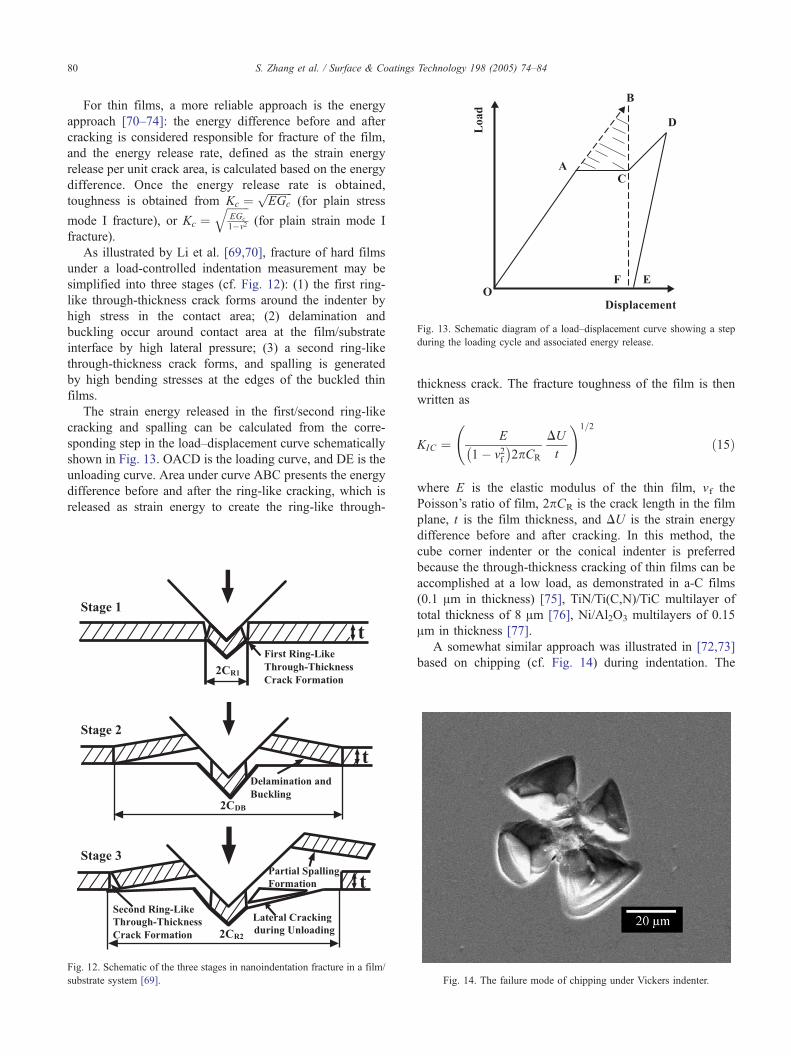
Fig. 13. Schematic diagram of a load–displacement curve showing a step
during the loading cycle and associated energy release.
S. Zhang et al. / Surface & Coatings Technology 198 (2005) 74–8480
For thin films, a more reliable approach is the energy
approach [70–74]: the energy difference before and after
cracking is considered responsible for fracture of the film,
and the energy release rate, defined as the strain energy
release per unit crack area, is calculated based on the energy
difference. Once the energy release rate is obtained,
toughness is obtained from Kc ¼ffiffiffiffiffiffiffiffiffiEGc
p(for plain stress
mode I fracture), or Kc ¼ffiffiffiffiffiffiffiffiEGc
1�m2
q(for plain strain mode I
fracture).
As illustrated by Li et al. [69,70], fracture of hard films
under a load-controlled indentation measurement may be
simplified into three stages (cf. Fig. 12): (1) the first ring-
like through-thickness crack forms around the indenter by
high stress in the contact area; (2) delamination and
buckling occur around contact area at the film/substrate
interface by high lateral pressure; (3) a second ring-like
through-thickness crack forms, and spalling is generated
by high bending stresses at the edges of the buckled thin
films.
The strain energy released in the first/second ring-like
cracking and spalling can be calculated from the corre-
sponding step in the load–displacement curve schematically
shown in Fig. 13. OACD is the loading curve, and DE is the
unloading curve. Area under curve ABC presents the energy
difference before and after the ring-like cracking, which is
released as strain energy to create the ring-like through-
Fig. 12. Schematic of the three stages in nanoindentation fracture in a film/
substrate system [69].
thickness crack. The fracture toughness of the film is then
written as
KIC ¼ E
1� v2f �
2pCR
DU
t
!1=2
ð15Þ
where E is the elastic modulus of the thin film, vf the
Poisson’s ratio of film, 2pCR is the crack length in the film
plane, t is the film thickness, and DU is the strain energy
difference before and after cracking. In this method, the
cube corner indenter or the conical indenter is preferred
because the through-thickness cracking of thin films can be
accomplished at a low load, as demonstrated in a-C films
(0.1 Am in thickness) [75], TiN/Ti(C,N)/TiC multilayer of
total thickness of 8 Am [76], Ni/Al2O3 multilayers of 0.15
Am in thickness [77].
A somewhat similar approach was illustrated in [72,73]
based on chipping (cf. Fig. 14) during indentation. The
Fig. 14. The failure mode of chipping under Vickers indenter.

S. Zhang et al. / Surface & Coatings Technology 198 (2005) 74–84 81
energy release rate during chipping under Berkovich
indenter is expressed as
C ¼ U cfr
3ptVCd
ð16Þ
where Cd is the diameter of the delamination crack that
initiated the chip, tV the effective film thickness, which
accounts the fact that the crack does not propagate
perpendicular to the film/substrate interface. tV equals to
the film thickness t divided by sin(d), where d is the average
angle of the chipping edge. Ufrc is the energy dissipated
during the chipping, which can be determined from
analyzing the irreversibly dissipated energy (total energy
minus the elastic energy) Wirr.
Ignoring the thermal energy, after one indentation cycle,
the irreversibly dissipated energy Wirr comprises the energy
dissipated due to the plastic deformation (Upl) and the
energy dissipated due to fracture or chipping (Ufr), or
Wirr ¼ Ufr þ Upl ð17Þ
Wirr can be determined through computing the area between
the loading and unloading curve. By plotting Wirr vs. the
indentation load, a curve can be obtained (cf. Fig. 15). The
onset of delamination changes the slope of the Wirr–P curve.
Before chipping takes place, the total irreversibly dissipated
energy comprises that for plastic deformation (Upl) and
delamination (Ufrd). Upon chipping, Ufr comprises two
components: the energy release in delamination, Ufrd and
the energy released in chipping, Ufrc, which is graphically
attainable from the Wirr–P curve (Fig. 15). Plugging the
chipping energy back to Eq. (16) gives rise to the critical
strain energy release rate, which in turn yields fracture
toughness through KIC ¼ffiffiffiffiffiffiffiEC
p.
Possible errors come from energy determination, crack
length, and area measurement due to irregularity in crack
shape. TiAlSiN thin films of hardness of 29–32.5 GPa and
thickness of 2 Am have been measured this way, and a
toughness of 1.55–2.1 MPa m1/2 is reported [78]. Malz-
Fig. 15. Energy irreversibly dissipated during indentation as a function of
the peak load applied during the indentation [72].
bender and de With used the SiO2-filled methyltrimethox-
ysilane films (thickness of 2–4 Am) to compare the
measurements of fracture toughness by radial cracking
method and the chipping method [79]. The results differ
from 0 to 22%.
2.5. Tensile testing
For relatively thick free-standing films, fracture tough-
ness can be directly measured using tensile method
according to the ASTM standard E-399 [3], where the
precrack is introduced easily by laser cutting, as in the case
of diamond films with thickness of 150–200 Am [80]. The
fracture toughness of the films is thus measured as 5–6 MPa
m1/2, comparable with those from indentation methods.
For thin films, however, measurement without creating
the precrack makes more sense because of the difficulties
and uncertainties involved in making precracks in micron or
submicron thin films. Harry et al. [81–83] have proposed a
microtensile method in which a flat rectangular substrate of
dimensions L (length)�w (width)�hs (thickness) coated
with a film of thickness hf is put under tension. In the
tension process, the cracking of the film causes energy
variations in the film/substrate system. For thin films
(hfbhs) coated on flat substrate (hsbL) with perfect
adhesion (thus, buckling of the film will not happen), the
film/substrate system can be regarded as a thin composite
beam. The toughness of the film is calculated based on
energy balance when the cracking occurs.
DU ¼rfc
�2hfð Þ2
Efpf
Ef
Es
� �þ rf
cffiffiffi3
prsy
( )ð18Þ
where DU is the net energy change, fEf
Es
�is a function of
the elastic modulus ratio, and the values are tabulated in
Ref. [84] for different modulus ratios, Ef and Es are the
Young’s modulus for film and substrate, respectively. rys is
the yield stress of the substrate. rcf is the effective critical
cracking stress which is experimentally determined. The
critical strain energy release rate for crack propagating
through the film Gcf is
Gfc ¼
DU
hf¼
rfc
�2hfð Þ
Efpf
Ef
Es
� ��þ rf
cffiffiffi3
prsy
�ð19Þ
Fracture toughness of the film KIC can be calculated
through Eq. (3) once Gcf is obtained. Harry et al. [81] de-
posited Wand W–C solid solution [W(C)] films of thickness
from 1.8 to 16 Am on stainless steel substrates and subjected
the film/substrate composite beams under tension and mea-
sured the fracture toughness of the W films as 1.0 to 2.5
MPa m1/2 and that of the W(C) films as 0.2 to 1.0 MPa m1/2.
The major drawback of this method lies in its require-
ment of substrate properties. Toughness of film is in fact a
property of the film itself and should not vary with substrate.

S. Zhang et al. / Surface & Coatings Technology 198 (2005) 74–8482
Zhang et al. [85] have proposed a two-step uniaxial tensile
method to characterize toughness of thin hard films. In this
method, the film/substrate system is subjected to uniaxial
tensile stress until the film fractures, while the substrate is
still elastic. After the loading is removed to allow substrate
complete elastic recovery, the system is subjected to a
second loading until the previous extension. The onset of
film fracture is determined by the loss of linearity in the
load–extension curve. Upon failure, parallel cracks are
generated in the film. The crack initiation and propagation
patterns are examined using SEM, and crack density
(number of crack per distance) is measured. The toughness
of the thin film is then derived from the energy difference
between the two subsequent load–extension curves (cf. Fig.
16). Assuming that the film adheres perfectly to the
substrate during loading and unloading, thus there is no
interfacial cracking (i.e., no adhesion failure); the elasticity
of the substrate material is good enough for it to remain
elastic while cracking occurs in the film; the aspect ratio of
length to thickness of the substrate is designed large enough
to warrant a plain stress condition. Under the assumption of
no adhesion failure, the energy variation DU in the film/
substrate system is attributed to the through-thickness
cracking in the film, which is the area difference of
SOABCEO–SODEO in Fig. 16.
DU ¼ZOABCEO
P1 xð Þdx�ZODEO
P2 xð Þdx ð20Þ
That can be experimentally determined and then related
to strain energy release rate. The energy release rate Gc is
defined as the strain energy release per unit crack area
[70,86]:
Gc ¼1
2
1
wqLf hð Þ
�dU
dC
���ð21Þ
where q is the crack density or number of cracks per unit
length (crack/Am) obtainable from the corresponding SEM
observations. w is the substrate width, L is the substrate
length, thus wqL is the total crack length in the film plane,
Fig. 16. Schematic diagram of load–extension curve obtained using the
two-step uniaxial tensile test under extension-control [85].
f(h) is a dimensionless factor dependent on crack orientation
( f(h)z1). For cracks perpendicular to the film/substrate
interface, f(h)=1. For thin film, the through-thickness cracks
propagate instantaneously, and the cracking is a single
event, i.e., dU/dC=DU/hf [70], and, when the cracks are
perpendicular to the interface, Eq. (21) is rewritten as
Gc ¼1
2
1
wqL
�DU
hf
���ð22Þ
where hf is the film thickness, 2wqLhf is the total crack area;DU is the strain energy difference before and after cracking.
Since the film is in plain stress condition under Mode I
fracture, Eq. (3) holds. Plugging Eq. (22) into Eq. (3) gives
rise to toughness KC as
KC ¼ E
2wqL
� ��DU
hf
�� �1=2ð23Þ
where E is the Young’s modulus of the thin film. A case
study of hard nanocomposite nc-TiN/a-SiNx films of 3.0 Amthick gives a toughness value of 2.6 MPa m1/2 [85].
The advantage of this two-step tensile method lies in its
independence from substrate properties, the ease, and speed
in experimentation. The principle of the method, data
treatment, and sample preparations are simple. In addition,
the tensile test covers more area, and the property thus
characterized is more close to the material intrinsic property
compared with the indentation or bending methods. The
drawback of the method is the elasticity requirement of the
substrate: the substrate has to remain in elastic deformation,
while the coated film has undergone fracture. The second
important requirement is the perfect adhesion between film
and substrate, without which significant variation in experi-
ment results may occur.
3. Summary and ending remarks
Toughness measurement for thin films is difficult due to
the small dimension in thickness. Until now, there is neither
standard procedure nor standard methodology. As in
qualitative or semiquantitative assessment, sometimes a
quick plasticity measurement or a scratch adhesion test (for
crack propagation resistance) will suffice. But these test
results should not be termed btoughness.QMore elaborate quantitative measurements can be cate-
gorized into two main groups: the stress approach and the
energy approach. The stress approach examines the stress
state near the tip of the crack. Toughness is obtained through
KCarf dffiffiffia
p. Bending with precrack, scratch in consideration
of critical tensile stress, crack length and spacing, and
indentation in consideration of the critical load and
corresponding crack length, etc., fall into this category.
Difficulties in these methods lie in the formation of the
precrack, determination of the crack length, and the critical

S. Zhang et al. / Surface & Coatings Technology 198 (2005) 74–84 83
failure stress. These problems are not easily resolved due to
the thickness dimension involved.
The energy approach concentrates on the system’s energy
state before and after fracture of the film. This energy
difference is considered consumed to increase new crack
area. Toughness is thus obtained through the critical energy
release rate Gc: KC ¼ffiffiffiffiffiffiffiffiffiEGc
p(for plain stress mode I
fracture) or KC ¼ffiffiffiffiffiffiffiffiEGc
1�v2
q(for plain strain mode I fracture),
where Gc is related to the energy difference (DU) and crack
area (DA) through Gc~DU=DA. Fallen under this category
are bending without precrack in the film, buckling,
indentation with chipping, tensile tests, and so on.
Standardization of thin film toughness measurements
seems necessary. Energy-based methodologies have clear
advantages over stress-based approach.
In order not to confuse with the classical concept of
fracture toughness, it is strongly suggested that the term
bfracture toughnessQ not be used in thin film toughness
description where precrack is not involved. Instead, simply,
btoughnessQ should suffice.
Acknowledgement
This work was supported by Nanyang Technical Uni-
versity’s research grant RG12/02.
References
[1] G.E. Dieter, Mechanical Metallurgy, 2nd ed., McGraw-Hill, 1976.
[2] W.D. Callister Jr., Materials Science and Engineering an Introduction,
6th ed., New York, Wilery, 2003.
[3] Standard Test for Plane Strain Fracture Toughness of Metallic
Materials, ASTME-399, American Society for Testing and Materials,
Philadelphia, PA, 1987.
[4] G.P. Cherepanov, Mechanics of Brittle Fracture, McGraw-Hill, 1979.
[5] D.K. Leung, M.Y. He, A.G. Evans, J. Mater. Res. 10 (1995) 1693.
[6] Z. Jiang, F.X. Lu, W.Z. Tang, S.G. Wang, Y.M. Tong, T.B. Huang,
J.M. Liu, Diamond Relat. Mater. 9 (2000) 1734.
[7] G. Jaeger, I. Endler, M. Heilmaier, K. Bartsch, A. Leonhardt, Thin
Solid Films 377–378 (2000) 382.
[8] G. Gille, K. Wetzig, Thin Solid Films 110 (1983) 37.
[9] G. Gille, Thin Solid Films 111 (1984) 201.
[10] L.C. Cox, Surf. Coat. Technol. 36 (1988) 807.
[11] H. Ollendorf, D. Schneider, Th. Schwarz, G. Kirchhoff, A. Mucha,
Surf. Coat. Technol. 84 (1996) 458.
[12] J. Von Stebut, F. Lapostolle, M. Bucsa, H. Vallen, Surf. Coat. Technol.
116–119 (1999) 160.
[13] D. Almond, M. Moghisi, H. Reiter, Thin Solid Films 108 (1983)
439.
[14] P.M. Ramsey, H.W. Chandler, T.F. Page, Thin Solid Films 201 (1991)
81.
[15] U. Wiklund, P. Hedenqvist, S. Hogmark, Surf. Coat. Technol. 97
(1997) 773.
[16] C.E. Kalnas, J.F. Mansfield, G.S. Was, J.W. Jones, J. Vac. Sci.
Technol., A 12 (3) (1994) 883.
[17] U. Wiklund, M. Bromark, M. Larsson, P. Hedenqvist, S. Hogmark,
Surf. Coat. Technol. 91 (1997) 57.
[18] B. Cotterell, Z. Chen, Int. J. Fract. 104 (2000) 169.
[19] Z. Chen, B. Cotterell, W. Wang, Eng. Fract. Mech. 69 (2002) 597.
[20] S.J. Britvec, The Stability of Elastic Systems, Pergamon Press, New
York, 1973.
[21] J.W. Hutchinson, Mechanics of Thin Films and Multilayers, Technical
University of Denmark, 1996.
[22] J.J.L. Beuth, Int. J. Solids Struct. 29 (1992) 1657.
[23] V. Bellido-Gonzalez, N. Stefanopoulos, F. Deguilhen, Surf. Coat.
Technol. 74–75 (1995) 884.
[24] X. Li, B. Bhushan, J. Mater. Res. 14 (6) (1999) 2328.
[25] S. Sundararajan, B. Bhushan, J. Mater. Res. 16 (2) (2001) 437.
[26] Peter Panjan, Miha Cekada, Boris Navinsek, Surf. Coat. Technol.
174–175 (2003) 55.
[27] A.A. Voevodin, C. Rebholz, J.M. Schneider, P. Stevenson, A.
Matthews, Surf. Coat. Technol. 73 (1995) 185.
[28] E. Harrry, A. Rouzaud, P. Juliet, Y. Pauleau, M. Ignat, Surf. Coat.
Technol. 116–119 (1999) 172.
[29] A.A. Voevodin, J.S. Zabinski, Thin Solid Films 370 (2000) 223.
[30] A.A. Voevodin, J.S. Zabinski, J. Mater. Sci. 33 (1998) 319.
[31] P.W. Shum, K.Y. Li, Z.F. Zhou, Y.G. Shen, Surf. Coat. Technol. 185
(2004) 245.
[32] J. Ligot, S. Benayoun, J.J. Hantzpergue, Wear 243 (2000) 85.
[33] S. Zhang, D. Sun, Y.Q. Fu, H. Du, Thin Solid Films 447–448 (2004)
462.
[34] J.W. Hoehn, S.K. Venkataraman, H. Huang, W.W. Gerberich, Mater.
Sci. Eng., A 192–193 (1995) 301.
[35] K. Holmberg, A. Laukkanen, H. Ronkainen, K. Wallin, S. Varjus,
Wear 254 (2003) 278.
[36] Yu. V. Milman, B.A. Galanov, S.I. Chugunova, Acta Metall. Mater.
V41 (9) (1993) 2523.
[37] A.A. Voevodin, M.S. Donley, Surf. Coat. Technol. 82 (1996) 199.
[38] A.A. Voevodin, S.V. Prasad, J.S. Zabinski, J. Appl. Phys. 82 (2)
(1997) 855.
[39] S. Zhang, X.L. Bui, Y.Q. Fu, Surf. Coat. Technol. 167 (2003) 137.
[40] T.Y. Tsui, J.V. Vlassak, M.D. Nix, J. Mater. Res. 14 (1999) 2204.
[41] T.Y. Tsui, Y. Joo, Thin Solid Films 401 (2001) 203.
[42] A.A. Wells, Br. Weld. J. 10 (1963) 563.
[43] J. Malzbender, G. de With, Surf. Coat. Technol. 137 (2001) 72.
[44] J. Malzbender, G. de With, Surf. Coat. Technol. 127 (2000) 265.
[45] R. McGurk, T.F. Page, J. Mater. Res. 14 (1999) 2283.
[46] H. Holleck, H. Schulz, Surf. Coat. Technol. 36 (1988) 707.
[47] F. Kustas, B. Mishra, J. Zhou, Surf. Coat. Technol. 120–121 (1999)
489.
[48] B.R. Lawn, A.G. Evans, D.B. Marshall, J. Am. Ceram. Soc. 63 (1980)
574.
[49] G.R. Anstis, P. Chantikul, B.R. Lawn, D.B. Marshall, J. Am. Ceram.
Soc. 64 (1981) 533.
[50] G.M. Pharr, D.S. Harding, W.C. Oliver, in: M. Nastasi, Don M.
Parkin, H. Gleiter (Eds.), Mechanical Properties and Deformation
Behavior of Materials Having Ultra-Fine Microstructure, Klumer
Academic Press, 1993, p. 449.
[51] A. A. Volinsky, J. B. Vella, W. W. Gerberich, Thin Solid Films 429
(2003) 201.
[52] W.C. Oliver, G.M. Phar, J. Mater. Res. 7 (1992) 1564.
[53] G.M. Pharr, Mater. Sci. Eng., A 253 (1998) 151.
[54] A.E. Giannakopoulos, P.-L. Larsson, R. Vestergaard, Int. J. Solids
Struct. V31 (19) (1994) 2679.
[55] W.C. Oliver, G.M. Pharr, J. Mater. Res. V19 (1) (2004) 3.
[56] T. Lube, T. Fett, Eng. Fract. Mech. 71 (2004) 2263.
[57] D.S. Harding, W.C. Oliver, G.M. Pharr, Mater. Res. Soc. Symp. Proc.
356 (1995) 663.
[58] T.W. Scharf, H. Deng, J.A. Barnard, J. Vac. Sci. Technol., A 15 (3)
(1997) 963.
[59] P. Kodali, K.C. Walter, M. Nastasi, Tribol. Int. V30 (8) (1997)
591.
[60] Y. Xie, H.M. Hawthorne, Wear 233–235 (1999) 293.
[61] X. Li, B. Bhushan, Thin Solid Films 340 (1999) 210.
[62] P. Jedrzejowski, J.E. Klemberg-Sapieha, L. Martinu, Thin Solid Films
426 (2003) 150.

S. Zhang et al. / Surface & Coatings Technology 198 (2005) 74–8484
[63] P. Jedrzejowski, J.E. Klemberg-Sapieha, L. Martinu, Thin Solid Films
466 (2004) 189.
[64] T. Fett, Eng. Fract. Mech. V52 (4) (1995) 773.
[65] D.B. Marshall, B.R. Lawn, J. Am. Ceram. Soc. 60 (1977) 86.
[66] J. Malzbender, G. de With, J.M.J. den Toonder, Thin Solid Films 366
(2000) 139.
[67] T. W. Scharf, H. Deng, J. A. Barnard, J. Vac. Sci. Technol., A 15 (3)
(1997) 963.
[68] Z. Xia, W.A. Curtin, B.W. Sheldon, Acta Mater. 52 (2004) 3507.
[69] X. Li, D. Diao, B. Bhushan, Acta Mater. 45 (11) (1997) 4453.
[70] X. Li, B. Bhushan, Thin Solid Films 315 (1998) 214.
[71] B. Bhushan, Diamond Relat. Mater 8 (1999) 1985.
[72] J.D. Toonder, J. Malzbender, G.D. With, R. Balkenende, J. Mater.
Res. 17 (1) (2002) 224.
[73] J. Malzbender, G. de With, Surf. Coat. Technol. 135 (2000) 60.
[74] J. Malzbender, J.M.J. den Toonder, A.R. Balkenende, G. de With,
Mater. Sci. Eng. R36 (2002) 47.
[75] X. Li, B. Bhushan, Thin Solid Films 355–356 (1999) 330.
[76] J. Ding, Y. Meng, S. Wen, Thin Solid Films 371 (2000) 178.
[77] S. Neralla, D. Kumar, S. Yarmolenko, J. Sankar, Composites, Part B
35 (2004) 157.
[78] O. Nakonechna, T. Cselle, M. Morstein, A. Karimi, Thin Solid Films
447–448 (2004) 406.
[79] J. Malzbender, G. de With, J. Non-Cryst. Solids 265 (2001) 51.
[80] M.D. Drory, R.H. Dauskardt, A. Kant, R.O. Ritchie, J. Appl. Phys. 78
(5) (1995) 3083.
[81] E. Harry, A. Rouzaud, M. Ignat, P. Juliet, Thin Solid Films 332 (1998)
195.
[82] E. Harry, M. Ignat, Y. Pauleau, A. Rouzaud, P. Juliet, Surf. Coat.
Technol. 125 (2000) 185.
[83] E. Harry, M. Ignat, A. Rouzaud, P. Juliet, Surf. Coat. Technol. 111
(1999) 177.
[84] M.S. Hu, A.G. Evans, Acta Metall. 37 (3) (1989) 917.
[85] S. Zhang, D. Sun, Y.Q. Fu, H. Du, Thin Solid Films (2004)
(in press).
[86] B.R. Lawn, Fracture of Brittle Solids, 2nd ed., Cambridge University
Press, Cambridge, U.K, 1993.