toshiba bar code printer b-sa4t...
TRANSCRIPT
TOSHIBA Bar Code Printer
B-SA4T Series Key Operation Specification
1st Edition: February 21, 2005 2nd Edition: April 20, 2005 3rd Edition: March 29, 2006 4th Edition: June 30, 2006 5th Edition: October 10, 2007 6th Edition: February 14, 2008 7th Edition: March 30, 2009 8th Edition: May 6, 2010 9th Edition: May 14, 2013 10th Edition: June 20, 2014

i
TABLE OF CONTENTS Page
1. SCOPE......................................................................................................................................... 1
2. OUTLINE ..................................................................................................................................... 1
3. OPERATION PANEL .................................................................................................................. 1
4. KEY OPERATION FLOW............................................................................................................ 2
5. ONLINE MODE............................................................................................................................ 3 5.1 KEY FUNCTIONS .................................................................................................................. 3
5.2 LED FUNCTIONS................................................................................................................... 3
5.3 LCD FUNCTIONS .................................................................................................................. 3
5.4 ONLINE MODE OPERATION EXAMPLE.............................................................................. 4
5.5 THRESHOLD SETTING......................................................................................................... 5
5.5.1 Outline of Threshold Setting ............................................................................................ 5
5.5.2 Threshold Setting Operation Example............................................................................. 5
5.6 INFORMATION MODE........................................................................................................... 7
5.6.1 Outline of the Information Mode....................................................................................... 7
5.6.2 Information Mode Operation Example ............................................................................. 8
5.6.3 Information Mode Print Sample ....................................................................................... 9
5.7 RESET.................................................................................................................................... 10
5.8 PARAMETER SETTING......................................................................................................... 11
5.8.1 Parameter Setting Operation Example ............................................................................ 11
5.8.2 Parameter Setting Items .................................................................................................. 16
5.9 FINE ADJUSTMENT VALUE SETTING................................................................................. 19
5.9.1 Fine Adjustment Value Setting Operation Example ........................................................ 19
5.9.2 Fine Adjustment Value Setting Items............................................................................... 22
5.10 DUMPING OF RECEIVE BUFFER ........................................................................................ 23
5.10.1 Operation Example of Receive Buffer Dumping.............................................................. 23
5.11 BASIC EXPANSION MODE................................................................................................... 23
5.12 AUTOMATIC CALIBRATION SETTING................................................................................. 27
5.12.1 Operation Example of Automatic Calibration Setting ...................................................... 27 5.13 LAN ENABLE/DISABLE SETTING ........................................................................................ 30
5.131 Operation Example of LAN Enable/Disable Setting ........................................................ 30 5.14 REAL TIME CLOCK (RTC) SETTING.................................................................................... 32
5.14.1 Operation Example of RTC Setting ................................................................................. 32 5.15 BASIC SETTING .................................................................................................................... 35
5.15.1 Operation Example of BASIC Setting .............................................................................. 35 5.16 Z-MODE SETTING................................................................................................................. 38
5.16.1 Outline of the Z-Mode .................................................................................................... 38 5.16.2 Operation Example of Z-Mode Setting ............................................................................ 38
5.17 LCD MESSAGES AND LED INDICATIONS .......................................................................... 40
ii
5.18 LCD MESSAGES IN DIFFERENT LANGUAGES (UPPER LINE OF LCD) .......................... 43
6. SYSTEM MODE........................................................................................................................... 45 6.1 OUTLINE OF SYSTEM MODE .............................................................................................. 45
6.2 SELF-TEST ............................................................................................................................ 47
6.2.1 Self-test Operation Example ............................................................................................ 47
6.2.2 Self-test Items .................................................................................................................. 51
6.2.2.1 Details of Self-test Result ....................................................................................... 56
6.3 VARIOUS PARAMETERS SETTING ..................................................................................... 67 6.3.1 Various Parameters Setting Operation Example ............................................................. 67
6.3.2 Details of Various Parameter Setting ............................................................................... 72
6.4 FINE ADJUSTMENT VALUE SETTING ................................................................................. 86
6.4.1 Fine Adjustment Value Setting Operation Example ........................................................ 86
6.4.2 Details of Fine Adjustment Value Setting ........................................................................ 88
6.5 TEST PRINT ........................................................................................................................... 96
6.5.1 Test Print Operation Example .......................................................................................... 96
6.5.2 Details of Test Print Setting ............................................................................................. 100
6.5.3 Test Print Samples ........................................................................................................... 104
6.6 SENSOR DISPLAY/ADJUSTMENT ....................................................................................... 109
6.6.1 Sensor Display/Adjustment Operation Example .............................................................. 109
6.6.2 Details of Sensor Adjustment Value Display ................................................................... 111
6.7 RAM CLEAR ........................................................................................................................... 112
6.7.1 RAM Clear Operation Example........................................................................................ 112
6.7.2 Details of RAM Clear ....................................................................................................... 114
6.8 IP ADDRESS SETTING ......................................................................................................... 118
6.8.1 IP Address Setting Operation Example ........................................................................... 118
6.8.2 IP Address Setting Operation Flow .................................................................................. 125
6.9 BASIC SETTING .................................................................................................................... 126
6.9.1 BASIC Setting Operation Example .................................................................................. 126
6.10 ADJUSTMENT MODE FOR FACTORY ................................................................................. 129
6.11 RFID SETTING ....................................................................................................................... 131
6.11.1 RFID Setting Operation Example..................................................................................... 131
6.11.2 Details of RFID Setting .................................................................................................... 135
6.12 Z-MODE SETTING ................................................................................................................. 144
6.12.1 Z-Mode Setting Operation Example ................................................................................ 144
7. DOWNLOAD MODE .................................................................................................................... 147
COPYRIGHT©2005-2014 TOSHIBA TEC Corporation All rights reserved
- 1 -
1. SCOPE This specification describes key operations of the B-SA4T Series general-purpose bar code printers (hereinafter referred to as “B-SA4T”) using the B-SA4T keys and the LCD display.
2. OUTLINE The B-SA4T key operations are performed roughly in two modes: online mode and system mode. In online mode, where the B-SA4T is connected to a host device such as a personal computer, the key operations are performed mainly to pause or restart the B-SA4T and to display printer status messages and error messages on the LCD. In system mode, the key operations are performed mainly to conduct a self-test and to make various parameter settings. This specification describes the key operations in these two modes and in download mode. For explanation purposes, this specification uses English key names and LCD messages, although other languages are available for key names and LCD messages.
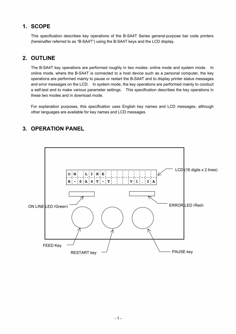
3. OPERATION PANEL
O N L I N E
B - S A 4 T - T V 1 . 2 A
ON LINE LED (Green) ERROR LED (Red)
LCD (16 digits x 2 lines)
FEED Key
RESTART key PAUSE key
- 2 -
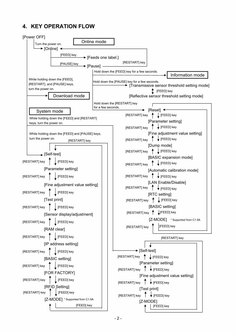
4. KEY OPERATION FLOW
Online mode
System mode
Download mode
[Power OFF]
[Transmissive sensor threshold setting mode]
[Reflective sensor threshold setting mode]
Turn the power on.
While holding down the [FEED] and [RESTART] keys, turn the power on.
While holding down the [FEED] and [PAUSE] keys, turn the power on.
[FEED] key
[RESTART] key
[RESTART] key
Hold down the [PAUSE] key for a few seconds.
Hold down the [RESTART] key for a few seconds.
[FEED] key
[PAUSE] key
[Online]
[Feeds one label.]
[Pause]
[Self-test]
[Parameter setting]
[Fine adjustment value setting]
[Test print]
[RESTART] key [FEED] key
[RESTART] key [FEED] key
[RESTART] key [FEED] key
[Sensor display/adjustment]
[RESTART] key [FEED] key
[RAM clear]
[RESTART] key [FEED] key
[IP address setting]
[RESTART] key [FEED] key
[BASIC setting]
[RESTART] key [FEED] key
[FEED] key
[Self-test]
[Fine adjustment value setting]
[Test print]
[RESTART] key [FEED] key
[RESTART] key [FEED] key
[RESTART] key
[FEED] key
[FOR FACTORY]
[RESTART] key [FEED] key
While holding down the [FEED], [RESTART], and [PAUSE] keys, turn the power on.
[Parameter setting] [RESTART] key [FEED] key
[RFID Setting]
[RESTART] key [FEED] key
[RESTART] key [FEED] key [Reset]
[Parameter setting]
[Fine adjustment value setting]
[Dump mode]
[RESTART] key [FEED] key
[RESTART] key [FEED] key
[RESTART] key [FEED] key
[BASIC expansion mode]
[Automatic calibration mode] [RESTART] key [FEED] key
[RESTART] key [FEED] key
[LAN Enable/Disable]
[RTC setting]
[RESTART] key [FEED] key
[BASIC setting] [RESTART] key [FEED] key
[RESTART] key [FEED] key
[Z-MODE]
[RESTART] key [FEED] key
[Z-MODE]
[RESTART] key [FEED] key
* Supported from C1.9A
* Supported from C1.9A [Z-MODE] [RESTART] key [FEED] key
Hold down the [FEED] key for a few seconds. Information mode
- 3 -
5. ONLINE MODE
5.1 KEY FUNCTIONS
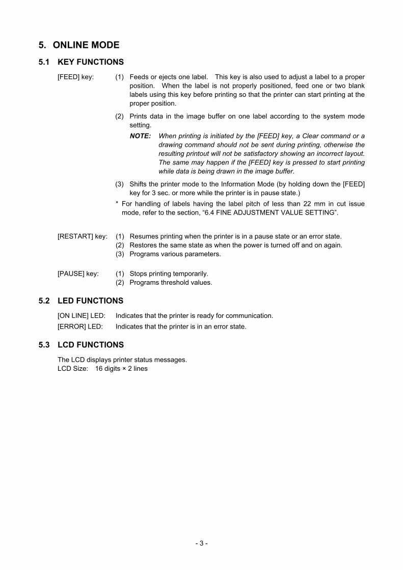
[FEED] key: (1) Feeds or ejects one label. This key is also used to adjust a label to a proper position. When the label is not properly positioned, feed one or two blank labels using this key before printing so that the printer can start printing at the proper position.
(2) Prints data in the image buffer on one label according to the system mode setting.
NOTE: When printing is initiated by the [FEED] key, a Clear command or a drawing command should not be sent during printing, otherwise the resulting printout will not be satisfactory showing an incorrect layout. The same may happen if the [FEED] key is pressed to start printing while data is being drawn in the image buffer.
(3) Shifts the printer mode to the Information Mode (by holding down the [FEED] key for 3 sec. or more while the printer is in pause state.)
* For handling of labels having the label pitch of less than 22 mm in cut issue mode, refer to the section, “6.4 FINE ADJUSTMENT VALUE SETTING”.
[RESTART] key: (1) Resumes printing when the printer is in a pause state or an error state. (2) Restores the same state as when the power is turned off and on again. (3) Programs various parameters. [PAUSE] key: (1) Stops printing temporarily. (2) Programs threshold values.
5.2 LED FUNCTIONS
[ON LINE] LED: Indicates that the printer is ready for communication. [ERROR] LED: Indicates that the printer is in an error state.
5.3 LCD FUNCTIONS
The LCD displays printer status messages. LCD Size: 16 digits × 2 lines

- 4 -
5.4 ONLINE MODE OPERATION EXAMPLE
Power ON
O N L I N E
B - S A 4 T - T V 1 . 2 A
* This message is displayed while the printer is idling or printing normally.
An error occurs.
N O P A P E R 1 2 5
B - S A 4 T - T V 1 . 2 A
* An error message is displayed when an error occurs during printing, then the printing stops. (The number of remaining labels to be printed is displayed at the right of the LCD.)
[RESTART] Load label paper and press the [RESTART] key.
O N L I N E
B - S A 4 T - T V 1 . 2 A
* This message is displayed and the printing resumes.
[PAUSE] Press the [PAUSE] key.
P A U S E 5 2
B - S A 4 T - T V 1 . 2 A
* When the [PAUSE] key is pressed during printing, this message is displayed and the printing stops. (The number of remaining labels to be printed is displayed at the right of the LCD.)
[RESTART] Press the [RESTART] key.
O N L I N E
B - S A 4 T - T V 1 . 2 A
* This message is displayed and the printingresumes.
NOTE: [Number of remaining labels to be printed] = [Total number of labels to be printed] - [Number of labels already printed before an error occurred or the printer stopped temporarily]
- 5 -
5.5 THRESHOLD SETTING
5.5.1 Outline of Threshold Setting
To always start printing at a proper position, the printer automatically corrects a print start position using a transmissive or reflective sensor. However, the printer sometimes fails to correct the print start position properly. For label papers, a transmissive sensor is used to detect a gap between labels. When preprinted labels are used, transmissivity may vary due to inks used, and the printer may not be able to correct the print start position properly. For tag papers with black marks printed on the back side, a reflective sensor is used to detect the black marks. When reflectivity of the area other than the black marks varies, the printer may not be able to correct the print start position properly. In these cases, the printer can correct the print start position properly by using a transmissive sensor threshold value/reflective sensor threshold value manually determined and stored in a non-volatile memory (EEPROM) by performing the key operation explained in the subsequent section, “Threshold Setting Operation Example” and by setting the type of sensor for Issue and Feed commands to “3: Transmissive Sensor (when using a manual threshold value)” or “4: Reflective Sensor (when using a manual threshold value)”.
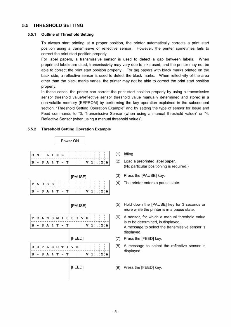
5.5.2 Threshold Setting Operation Example
Power ON
O N L I N E (1) Idling
B - S A 4 T - T V 1 . 2 A
(2) Load a preprinted label paper. (No particular positioning is required.)
[PAUSE] (3) Press the [PAUSE] key.
P A U S E
B - S A 4 T - T V 1 . 2 A
(4) The printer enters a pause state.
[PAUSE] (5) Hold down the [PAUSE] key for 3 seconds ormore while the printer is in a pause state.
T R A N S M I S S I V E
B - S A 4 T - T V 1 . 2 A
(6) A sensor, for which a manual threshold value is to be determined, is displayed. A message to select the transmissive sensor is displayed.
[FEED] (7) Press the [FEED] key.
R E F L E C T I V E
B - S A 4 T - T V 1 . 2 A
(8) A message to select the reflective sensor is displayed.
[FEED] (9) Press the [FEED] key.

- 6 -
T R A N S M I S S I V E
B - S A 4 T - T V 1 . 2 A
(10) A message to select the transmissive sensor is displayed.
[PAUSE] (11) Continue holding down the [PAUSE] key.
T R A N S M I S S I V E
B - S A 4 T - T V 1 . 2 A
(12) Release the [PAUSE] key when 1.5 or more labels are fed to stop printing. (The threshold setting for the selected sensor (transmissive sensor in this example) is completed.
P A U S E (13) The printer enters a pause state.
B - S A 4 T - T V 1 . 2 A
[RESTART] (14) Press the [RESTART] key.
O N L I N E (15) Idling
B - S A 4 T - T V 1 . 2 A
Command
O N L I N E
B - S A 4 T - T V 1 . 2 A
(16) The printer starts printing according to a command sent from a PC.
<Supplementary Explanations>
(1) When the [PAUSE] key is pressed and released within 3 seconds while the printer is paused, no action is taken.
(2) To obtain an accurate threshold value, 1.5 or more labels should be fed. (If less than 1.5 labels are fed, the threshold value may not be accurate enough to start printing at a proper print start position. If the print start position is not correct, the threshold setting operation should be performed again.)
(3) When the [PAUSE] key is held down for 3 seconds or more with the head lifted, no action is taken.
(4) While the printer is feeding labels to determine a threshold value, no errors, including paper end error and cutter error, are detected.
(5) If the printer still does not start printing at the proper print start position after the threshold setting operation is performed, it can be suspected that a sensor adjustment is not proper. In this case, readjust the sensor in system mode, then perform the threshold setting operation again.
When the backing paper of a label paper is too thick, the transmissive sensor should be readjusted. In addition, make sure that the type of sensor for Issue and Feed commands is set to “3: Transmissive sensor (when using a manual threshold value)” or “4: Reflective sensor (when using a manual threshold value)”.
- 7 -
5.6 INFORMATION MODE
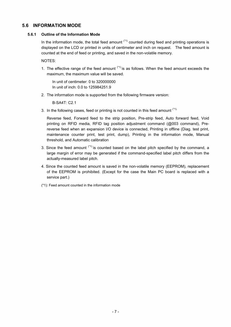
5.6.1 Outline of the Information Mode
In the information mode, the total feed amount (*1) counted during feed and printing operations is displayed on the LCD or printed in units of centimeter and inch on request. The feed amount is counted at the end of feed or printing, and saved in the non-volatile memory.
NOTES:
1. The effective range of the feed amount (*1) is as follows. When the feed amount exceeds the
maximum, the maximum value will be saved.
In unit of centimeter: 0 to 320000000 In unit of inch: 0.0 to 125984251.9
2. The information mode is supported from the following firmware version:
B-SA4T: C2.1
3. In the following cases, feed or printing is not counted in this feed amount (*1).
Reverse feed, Forward feed to the strip position, Pre-strip feed, Auto forward feed, Void printing on RFID media, RFID tag position adjustment command (@003 command), Pre-reverse feed when an expansion I/O device is connected, Printing in offline (Diag. test print, maintenance counter print, test print, dump), Printing in the information mode, Manual threshold, and Automatic calibration
3. Since the feed amount (*1) is counted based on the label pitch specified by the command, a
large margin of error may be generated if the command-specified label pitch differs from the actually-measured label pitch.
4. Since the counted feed amount is saved in the non-volatile memory (EEPROM), replacement of the EEPROM is prohibited. (Except for the case the Main PC board is replaced with a service part.)
(*1): Feed amount counted in the information mode

- 8 -
5.6.2 Information Mode Operation Example
O N L I N E
B - S A 4 T C 2 . 1
P A U S E
B - S A 4 T C 2 . 1
3 2 0 0 0 0 0 0 0 c m
B - S A 4 T C 2 . 1
O N L I N E
B - S A 4 T C 2 . 1
(Supplementary Explanation)
(1) When printing is performed in this mode, a quick reset is performed.
Performing a quick reset causes the print count (number of labels issued) to be reset to zero and the image buffer to be cleared. When the automatic calibration is enabled, a calibration is performed after a quick reset. When the automatic call at power on parameter is enabled in the Saved data call command, saved data will be called after a quick reset.
(2) Previous print conditions are applied to the printing performed in this mode, except:
• Printing direction When the mirror printing has been specified, only the mirror printing is not performed. Therefore, the bottom first mirror printing and top first mirror printing will be changed to bottom first printing and top first printing, respectively.
• Effective print width and X-coordinate fine adjustment When the number of digits of the feed amount reaches the max. number of digits (74 mm), the feed amount is center-aligned.
(3) Before shifting to the Information mode, make sure that the printer has not received any commands related to feed or drawing. If the printer has received such commands, printing will not be performed and the printer will return to the normal state. At this time, a quick reset will not be performed.
(4) Do not send a command to the printer while in the information mode.
(5-1) Counted feed amount is displayed on the LCD (in units of cm).
(5-2) The unit of measure is switched between centimeter and inch by pressing the [RESTART] key.
(6-1) Press the [FEED] key to return to the idle state (1).
(6-2) Press the [PAUSE] key to print the feed amount. (7) The printer is reset.
(2) Press the [PAUSE] key. (3) The printer enters Pause state.
(1) Idle
[PAUSE]
Power ON
(4) Hold down the [FEED] key for 3 seconds or more while the printer is in pause state. [FEED]
[PAUSE]
(8) The printer returns to the idle state (1).
- 9 -
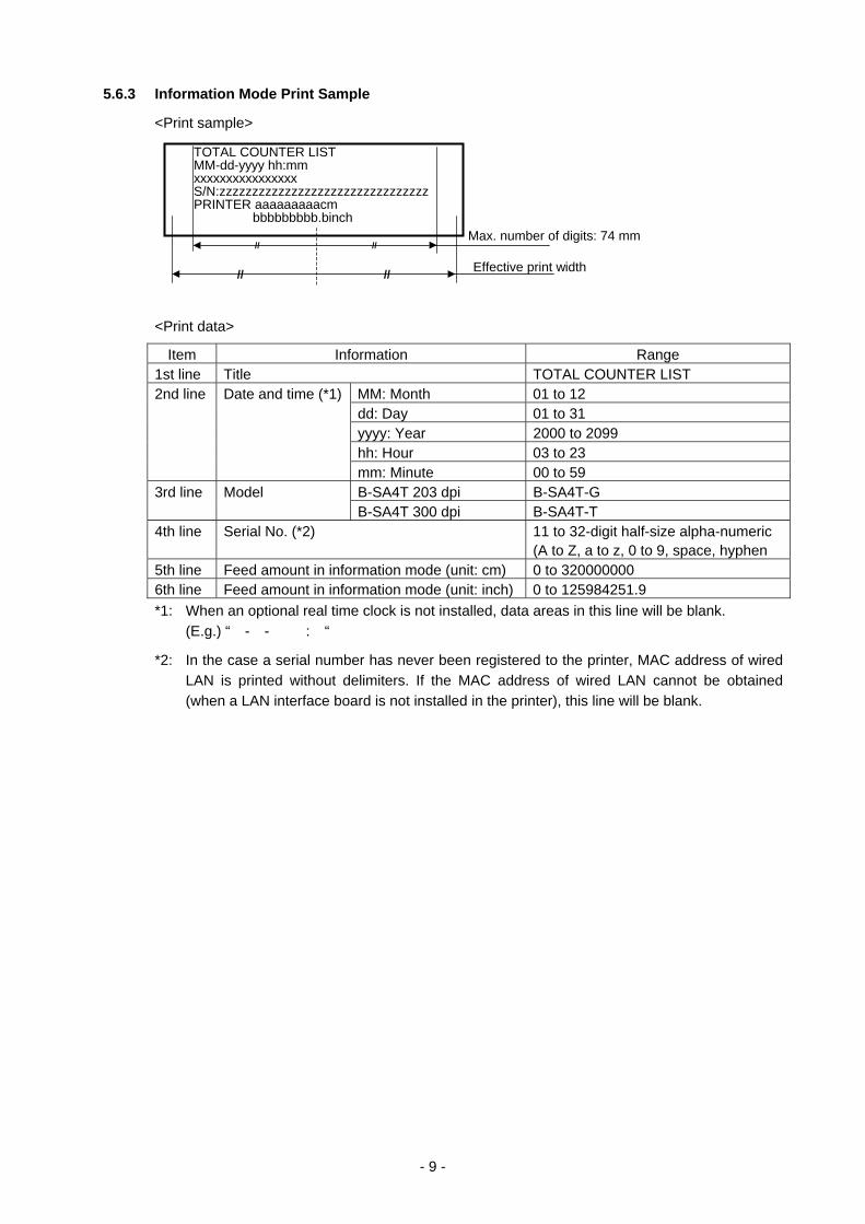
5.6.3 Information Mode Print Sample
<Print sample>
<Print data>
Item Information Range 1st line Title TOTAL COUNTER LIST 2nd line Date and time (*1) MM: Month 01 to 12 dd: Day 01 to 31 yyyy: Year 2000 to 2099 hh: Hour 03 to 23 mm: Minute 00 to 59
B-SA4T 203 dpi B-SA4T-G 3rd line Model B-SA4T 300 dpi B-SA4T-T
4th line Serial No. (*2) 11 to 32-digit half-size alpha-numeric (A to Z, a to z, 0 to 9, space, hyphen
5th line Feed amount in information mode (unit: cm) 0 to 320000000 6th line Feed amount in information mode (unit: inch) 0 to 125984251.9 *1: When an optional real time clock is not installed, data areas in this line will be blank.
(E.g.) “ - - : “
*2: In the case a serial number has never been registered to the printer, MAC address of wired LAN is printed without delimiters. If the MAC address of wired LAN cannot be obtained (when a LAN interface board is not installed in the printer), this line will be blank.
TOTAL COUNTER LIST MM-dd-yyyy hh:mm xxxxxxxxxxxxxxxx S/N:zzzzzzzzzzzzzzzzzzzzzzzzzzzzzzzz PRINTER aaaaaaaaacm bbbbbbbbb.binch
// //Max. number of digits: 74 mm
//// Effective print width
- 10 -
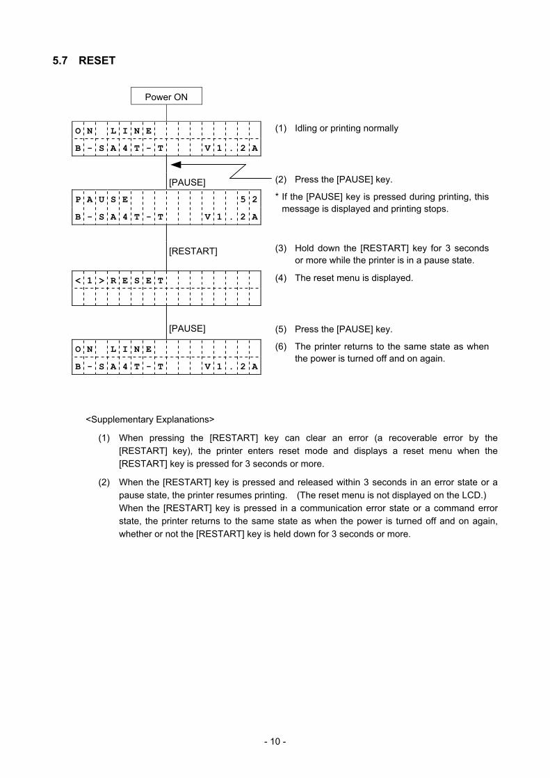
5.7 RESET
Power ON
O N L I N E (1) Idling or printing normally
B - S A 4 T - T V 1 . 2 A
[PAUSE] (2) Press the [PAUSE] key.
P A U S E 5 2
B - S A 4 T - T V 1 . 2 A
* If the [PAUSE] key is pressed during printing, this message is displayed and printing stops.
[RESTART] (3) Hold down the [RESTART] key for 3 seconds or more while the printer is in a pause state.
< 1 > R E S E T (4) The reset menu is displayed.
[PAUSE] (5) Press the [PAUSE] key.
O N L I N E
B - S A 4 T - T V 1 . 2 A
(6) The printer returns to the same state as when the power is turned off and on again.
<Supplementary Explanations>
(1) When pressing the [RESTART] key can clear an error (a recoverable error by the [RESTART] key), the printer enters reset mode and displays a reset menu when the [RESTART] key is pressed for 3 seconds or more.
(2) When the [RESTART] key is pressed and released within 3 seconds in an error state or a pause state, the printer resumes printing. (The reset menu is not displayed on the LCD.) When the [RESTART] key is pressed in a communication error state or a command error state, the printer returns to the same state as when the power is turned off and on again, whether or not the [RESTART] key is held down for 3 seconds or more.

- 11 -
5.8 PARAMETER SETTING
5.8.1 Parameter Setting Operation Example
Power ON
O N L I N E (1) Idling or printing normally
B - S A 4 T - T V 1 . 2 A
[PAUSE] (2) Press the [PAUSE] key.
P A U S E 5 2 (3) “PAUSE” is displayed.
B - S A 4 T - T V 1 . 2 A
[RESTART] (4) Hold down the [RESTART] key for 3 seconds or more while the printer is a pause state.
< 1 > R E S E T (5) The reset menu is displayed.
[FEED] (6) Press the [FEED] key.
< 2 > P A R A M E T E R S E T
(7) System mode menu display (Parameter setting)
[PAUSE] (8) Press the [PAUSE] key.
< 2 > P A R A M E T E R S E T
F O N T C O D E P C - 8 5 0
(9) Character code setting: Select a character code using the [FEED] and
[RESTART] keys.
[PAUSE] (10) Press the [PAUSE] key.
< 2 > P A R A M E T E R S E T
Z E R O F O N T 0
(11) Font 0 setting: Select a style of zero (0) using the [FEED] and
[RESTART] keys.
[PAUSE] (12) Press the [PAUSE] key.
< 2 > P A R A M E T E R S E T
S P E E D 9 6 0 0 b p s
(13) RS232C communication speed setting: Select a communication speed using the
[FEED] and [RESTART] keys.
[PAUSE] (14) Press the [PAUSE] key.
< 2 > P A R A M E T E R S E T
D A T A L E N G . 8 b i t s
(15) RS232C data length setting: Select a data length using the [FEED] and
[RESTART] keys.
[PAUSE] (16) Press the [PAUSE] key.
- 12 -
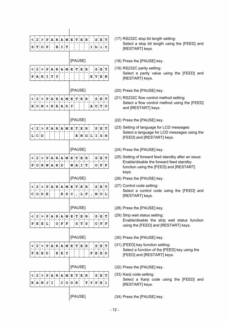
< 2 > P A R A M E T E R S E T
S T O P B I T 1 b i t
(17) RS232C stop bit length setting: Select a stop bit length using the [FEED] and
[RESTART] keys.
[PAUSE] (18) Press the [PAUSE] key.
< 2 > P A R A M E T E R S E T
P A R I T Y E V E N
(19) RS232C parity setting: Select a parity value using the [FEED] and
[RESTART] keys.
[PAUSE] (20) Press the [PAUSE] key.
< 2 > P A R A M E T E R S E T
X O N + R E A D Y A U T O
(21) RS232C flow control method setting: Select a flow control method using the [FEED]
and [RESTART] keys.
[PAUSE] (22) Press the [PAUSE] key.
< 2 > P A R A M E T E R S E T
L C D E N G L I S H
(23) Setting of language for LCD messages: Select a language for LCD messages using the
[FEED] and [RESTART] keys.
[PAUSE] (24) Press the [PAUSE] key.
< 2 > P A R A M E T E R S E T
F O R W A R D W A I T O F F
(25) Setting of forward feed standby after an issue: Enable/disable the forward feed standby
function using the [FEED] and [RESTART] keys.
[PAUSE] (26) Press the [PAUSE] key.
< 2 > P A R A M E T E R S E T
C O D E E S C , L F , N U L
(27) Control code setting: Select a control code using the [FEED] and
[RESTART] keys.
[PAUSE] (28) Press the [PAUSE] key.
< 2 > P A R A M E T E R S E T
P E E L O F F S T S O F F
(29) Strip wait status setting: Enable/disable the strip wait status function
using the [FEED] and [RESTART] keys.
[PAUSE] (30) Press the [PAUSE] key.
< 2 > P A R A M E T E R S E T
F E E D K E Y F E E D
(31) [FEED] key function setting: Select a function of the [FEED] key using the
[FEED] and [RESTART] keys.
[PAUSE] (32) Press the [PAUSE] key.
< 2 > P A R A M E T E R S E T
K A N J I C O D E T Y P E 1
(33) Kanji code setting: Select a Kanji code using the [FEED] and
[RESTART] keys.
[PAUSE] (34) Press the [PAUSE] key.

- 13 -
< 2 > P A R A M E T E R S E T
E U R O C O D E B 0
(35) Euro code setting: Select a Euro code using the [FEED] and
[RESTART] keys.
[PAUSE] (36) Press the [PAUSE] key.
< 2 > P A R A M E T E R S E T
A U T O H D C H K O F F
(37) Automatic head broken dots check setting: Enable/disable the automatic head broken dots
check using the [FEED] and [RESTART] keys.
[PAUSE] (38) Press the [PAUSE] key.
< 2 > P A R A M E T E R S E T
A C K / B U S Y T Y P E 1
(39) Centronics ACK/BUSY timing setting: Select an ACK/BUSY timing using the [FEED]
and [RESTART] keys.
[PAUSE] (40) Press the [PAUSE] key.
< 2 > P A R A M E T E R S E T
W E B P R I N T E R O F F
(41) Web printer function setting: Enable/disable the web printer function using
the [FEED] and [RESTART] keys.
[PAUSE] (42) Press the [PAUSE] key.
< 2 > P A R A M E T E R S E T
I N P U T P R I M E O N
(43) Setting of reset process when the nInit signal is ON:
Enable/disable the reset process function using the [FEED] and [RESTART] keys.
[PAUSE] (44) Press the [PAUSE] key.
< 2 > P A R A M E T E R S E T
R B N N E A R E N D 7 0 m
(45) Ribbon near end detection setting: Select a remaining ribbon length to be detected
as a ribbon near end state using the [FEED] and [RESTART] keys.
[PAUSE] (46) Press the [PAUSE] key.
< 2 > P A R A M E T E R S E T
E X . I / O T Y P E 1
(47) Expansion I/O operation mode setting: Select an expansion I/O operation mode using
the [FEED] and [RESTART] keys.
[PAUSE] (48) Press the [PAUSE] key.
< 2 > P A R A M E T E R S E T
P L U G & P L A Y O F F
(49) Plug-and-play operation setting: Enable/disable the plug-and-play operation
function using the [FEED] and [RESTART] keys.
[PAUSE] (50) Press the [PAUSE] key.
< 2 > P A R A M E T E R S E T
L B L / R B N E N D T Y P 1
(51) Label end/ribbon error process setting: Select a label end/ribbon error process using
the [FEED] and [RESTART] keys.
[PAUSE] (52) Press the [PAUSE] key.
- 14 -
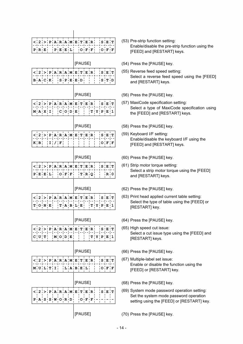
< 2 > P A R A M E T E R S E T
P R E P E E L O F F O F F
(53) Pre-strip function setting: Enable/disable the pre-strip function using the
[FEED] and [RESTART] keys.
[PAUSE] (54) Press the [PAUSE] key.
< 2 > P A R A M E T E R S E T
B A C K S P E E D S T D
(55) Reverse feed speed setting: Select a reverse feed speed using the [FEED]
and [RESTART] keys.
[PAUSE] (56) Press the [PAUSE] key.
< 2 > P A R A M E T E R S E T
M A X I C O D E T Y P E 1
(57) MaxiCode specification setting: Select a type of MaxiCode specification using
the [FEED] and [RESTART] keys.
[PAUSE] (58) Press the [PAUSE] key.
< 2 > P A R A M E T E R S E T
K B I / F O F F
(59) Keyboard I/F setting: Enable/disable the keyboard I/F using the [FEED] and [RESTART] keys.
[PAUSE] (60) Press the [PAUSE] key.
< 2 > P A R A M E T E R S E T
P E E L O F F T R Q R 0
(61) Strip motor torque setting: Select a strip motor torque using the [FEED] and [RESTART] keys.
[PAUSE] (62) Press the [PAUSE] key.
< 2 > P A R A M E T E R S E T
T O N E T A B L E T Y P E 1
(63) Print head applied current table setting: Select the type of table using the [FEED] or [RESTART] key.
[PAUSE] (64) Press the [PAUSE] key.
< 2 > P A R A M E T E R S E T
C U T M O D E T Y P E 1
(65) High speed cut issue: Select a cut issue type using the [FEED] and [RESTART] keys.
[PAUSE] (66) Press the [PAUSE] key.
< 2 > P A R A M E T E R S E T
M U L T I L A B E L O F F
(67) Multiple-label set issue: Enable or disable the function using the [FEED] or [RESTART] key.
[PAUSE] (68) Press the [PAUSE] key.
< 2 > P A R A M E T E R S E T
P A S S W O R D O F F - - - -
(69) System mode password operation setting: Set the system mode password operation setting using the [FEED] or [RESTART] key.
[PAUSE] (70) Press the [PAUSE] key.

- 15 -
< 2 > P A R A M E T E R S E T (71) The parameter setting menu is displayed.

- 16 -
5.8.2 Parameter Setting Items For details, refer to the section, “6.3 VARIOUS PARAMETER SETTING”.
(1) Character code (FONT CODE) • PC-850 • PC-852 • PC-857 • PC-8 • PC-851 • PC-855 • PC-1250 • PC-1251 • PC-1252 • PC-1253 • PC-1254 • PC-1257 • LATIN9 • Arabic • PC-855 • PC-866 • UTF-8
(2) Font 0 (ZERO FONT) • 0 (without slash) • 0 (with slash)
(3) RS-232C communication speed (SPEED) • 2400 bps • 4800 bps • 9600 bps • 19200 bps • 38400 bps • 115200 bps
(4) RS-232C data length (DATA LENG.) • 7 bits • 8 bits
(5) RS-232C stop bit length (STOP BIT) • 1 bit • 2 bits
(6) RS-232C parity (PARITY) • NONE • EVEN • ODD
(7) RS-232C flow control method (XON+READY) • XON/XOFF protocol (An XON is not output when the power is
on and an XOFF is not output when the power is off.)
• READY/BUSY (DTR) protocol (An XON is not output when the power is on and an XOFF is not output when the power is off.)
• XON/XOFF + READY/BUSY (DTR) protocol (An XON is output when the power is on and an XOFF is output when the power is off)
• XON/XOFF protocol (An XON is output when the power is on and an XOFF is output when the power is off)
• RTS protocol (An XON is not output when the power is on and an XOFF is not output when the power is off)
- 17 -
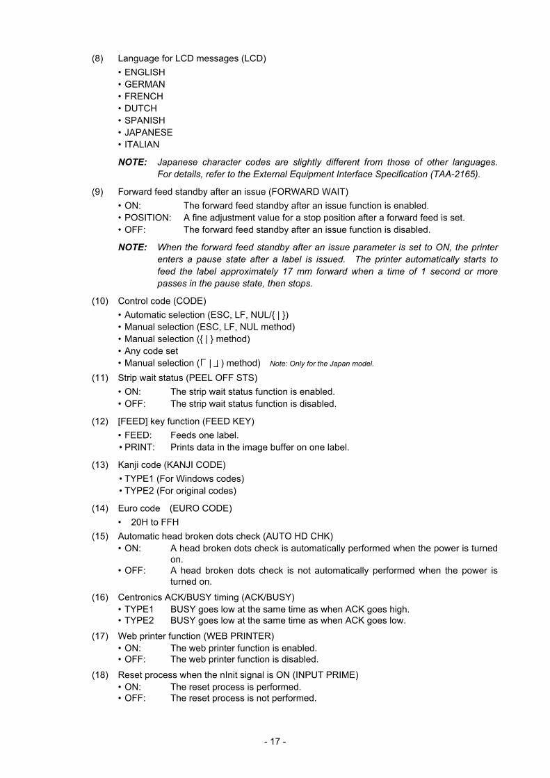
(8) Language for LCD messages (LCD) • ENGLISH • GERMAN • FRENCH • DUTCH • SPANISH • JAPANESE • ITALIAN
NOTE: Japanese character codes are slightly different from those of other languages. For details, refer to the External Equipment Interface Specification (TAA-2165).
(9) Forward feed standby after an issue (FORWARD WAIT) • ON: The forward feed standby after an issue function is enabled. • POSITION: A fine adjustment value for a stop position after a forward feed is set. • OFF: The forward feed standby after an issue function is disabled.
NOTE: When the forward feed standby after an issue parameter is set to ON, the printer enters a pause state after a label is issued. The printer automatically starts to feed the label approximately 17 mm forward when a time of 1 second or more passes in the pause state, then stops.
(10) Control code (CODE) • Automatic selection (ESC, LF, NUL/{ | }) • Manual selection (ESC, LF, NUL method) • Manual selection ({ | } method) • Any code set • Manual selection ( | ) method) Note: Only for the Japan model.
(11) Strip wait status (PEEL OFF STS) • ON: The strip wait status function is enabled. • OFF: The strip wait status function is disabled.
(12) [FEED] key function (FEED KEY) • FEED: Feeds one label. • PRINT: Prints data in the image buffer on one label.
(13) Kanji code (KANJI CODE) • TYPE1 (For Windows codes) • TYPE2 (For original codes)
(14) Euro code (EURO CODE) • 20H to FFH (15) Automatic head broken dots check (AUTO HD CHK)
• ON: A head broken dots check is automatically performed when the power is turned on.
• OFF: A head broken dots check is not automatically performed when the power is turned on.
(16) Centronics ACK/BUSY timing (ACK/BUSY) • TYPE1 BUSY goes low at the same time as when ACK goes high. • TYPE2 BUSY goes low at the same time as when ACK goes low.
(17) Web printer function (WEB PRINTER) • ON: The web printer function is enabled. • OFF: The web printer function is disabled.
(18) Reset process when the nInit signal is ON (INPUT PRIME) • ON: The reset process is performed. • OFF: The reset process is not performed.
- 18 -
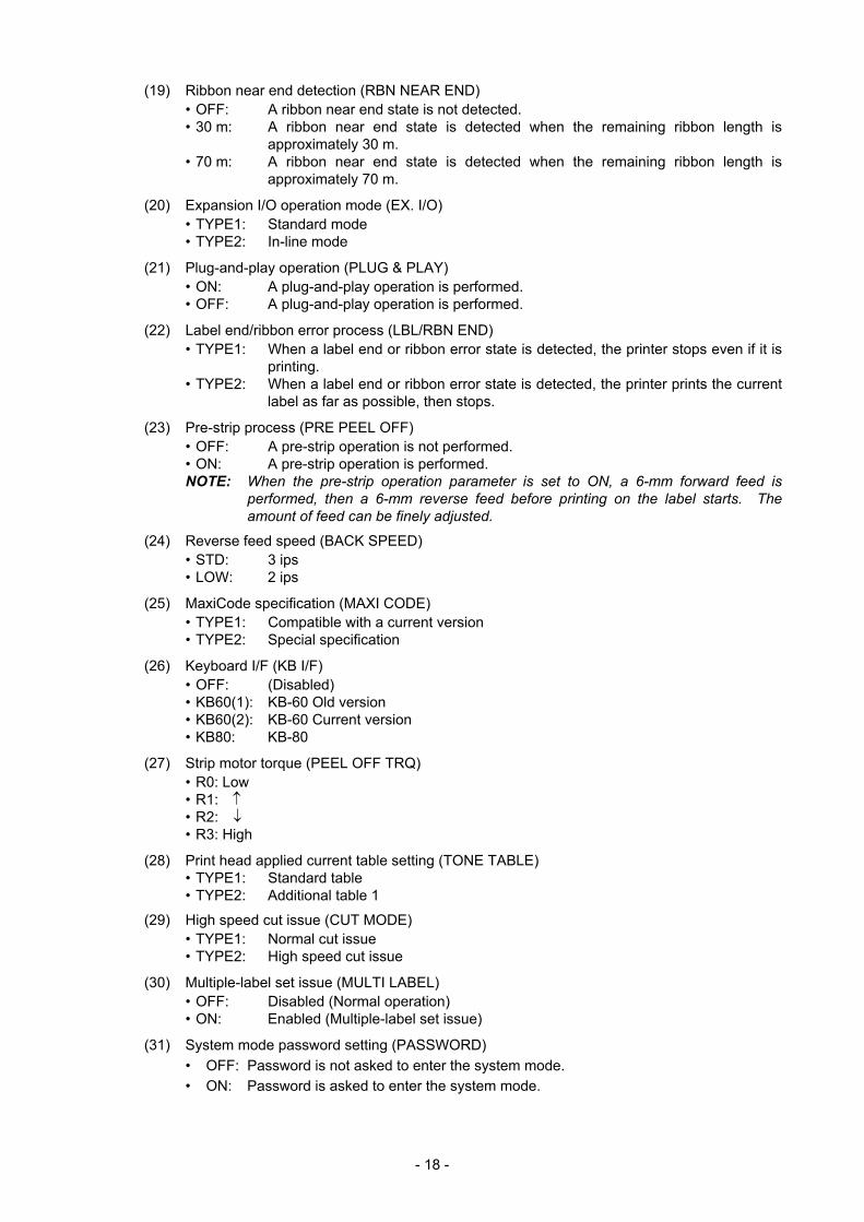
(19) Ribbon near end detection (RBN NEAR END) • OFF: A ribbon near end state is not detected. • 30 m: A ribbon near end state is detected when the remaining ribbon length is
approximately 30 m. • 70 m: A ribbon near end state is detected when the remaining ribbon length is
approximately 70 m.
(20) Expansion I/O operation mode (EX. I/O) • TYPE1: Standard mode • TYPE2: In-line mode
(21) Plug-and-play operation (PLUG & PLAY) • ON: A plug-and-play operation is performed. • OFF: A plug-and-play operation is performed.
(22) Label end/ribbon error process (LBL/RBN END) • TYPE1: When a label end or ribbon error state is detected, the printer stops even if it is
printing. • TYPE2: When a label end or ribbon error state is detected, the printer prints the current
label as far as possible, then stops.
(23) Pre-strip process (PRE PEEL OFF) • OFF: A pre-strip operation is not performed. • ON: A pre-strip operation is performed.
NOTE: When the pre-strip operation parameter is set to ON, a 6-mm forward feed is performed, then a 6-mm reverse feed before printing on the label starts. The amount of feed can be finely adjusted.
(24) Reverse feed speed (BACK SPEED) • STD: 3 ips • LOW: 2 ips
(25) MaxiCode specification (MAXI CODE) • TYPE1: Compatible with a current version • TYPE2: Special specification
(26) Keyboard I/F (KB I/F) • OFF: (Disabled) • KB60(1): KB-60 Old version • KB60(2): KB-60 Current version • KB80: KB-80
(27) Strip motor torque (PEEL OFF TRQ) • R0: Low • R1: ↑ • R2: ↓ • R3: High
(28) Print head applied current table setting (TONE TABLE) • TYPE1: Standard table • TYPE2: Additional table 1
(29) High speed cut issue (CUT MODE) • TYPE1: Normal cut issue • TYPE2: High speed cut issue
(30) Multiple-label set issue (MULTI LABEL) • OFF: Disabled (Normal operation) • ON: Enabled (Multiple-label set issue)
(31) System mode password setting (PASSWORD) • OFF: Password is not asked to enter the system mode. • ON: Password is asked to enter the system mode.
- 19 -
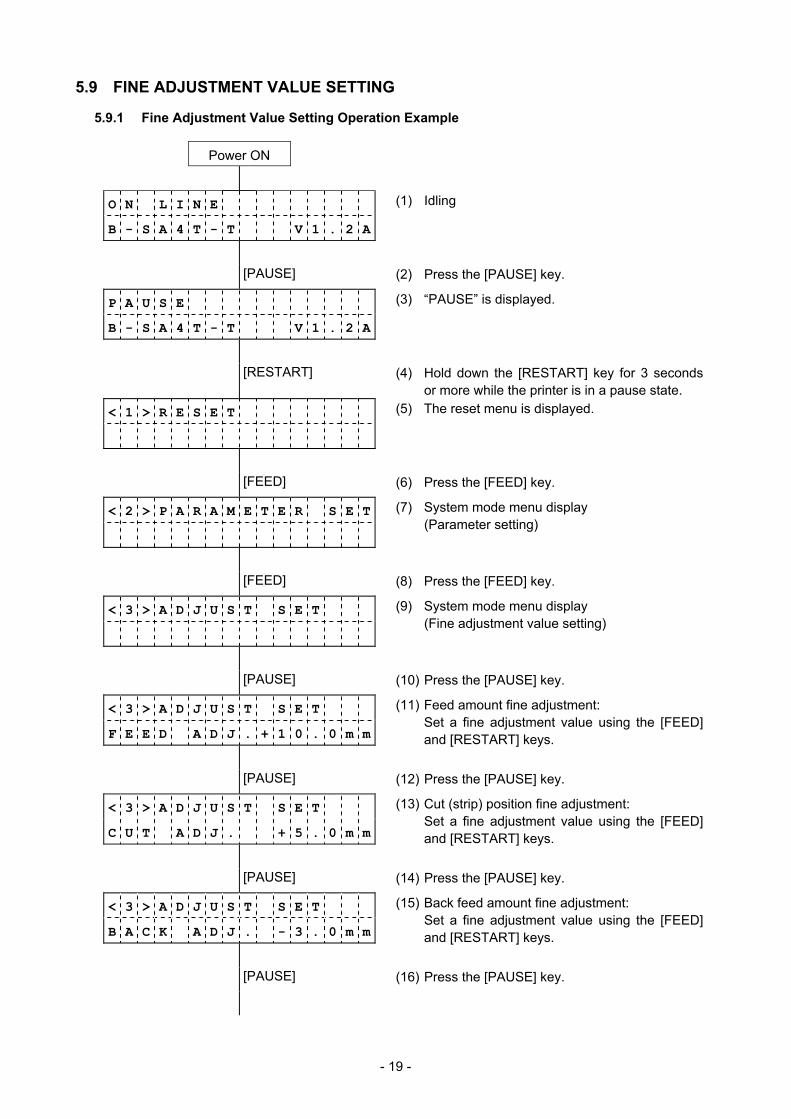
5.9 FINE ADJUSTMENT VALUE SETTING
5.9.1 Fine Adjustment Value Setting Operation Example
Power ON
O N L I N E (1) Idling
B - S A 4 T - T V 1 . 2 A
[PAUSE] (2) Press the [PAUSE] key.
P A U S E (3) “PAUSE” is displayed.
B - S A 4 T - T V 1 . 2 A
[RESTART] (4) Hold down the [RESTART] key for 3 seconds or more while the printer is in a pause state.
< 1 > R E S E T (5) The reset menu is displayed.
[FEED] (6) Press the [FEED] key.
< 2 > P A R A M E T E R S E T
(7) System mode menu display (Parameter setting)
[FEED] (8) Press the [FEED] key.
< 3 > A D J U S T S E T
(9) System mode menu display (Fine adjustment value setting)
[PAUSE] (10) Press the [PAUSE] key.
< 3 > A D J U S T S E T
F E E D A D J . + 1 0 . 0 m m
(11) Feed amount fine adjustment: Set a fine adjustment value using the [FEED]
and [RESTART] keys.
[PAUSE] (12) Press the [PAUSE] key.
< 3 > A D J U S T S E T
C U T A D J . + 5 . 0 m m
(13) Cut (strip) position fine adjustment: Set a fine adjustment value using the [FEED]
and [RESTART] keys.
[PAUSE] (14) Press the [PAUSE] key.
< 3 > A D J U S T S E T
B A C K A D J . - 3 . 0 m m
(15) Back feed amount fine adjustment: Set a fine adjustment value using the [FEED]
and [RESTART] keys.
[PAUSE] (16) Press the [PAUSE] key.
- 20 -
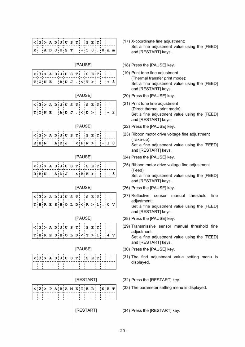
< 3 > A D J U S T S E T
X A D J U S T + 5 0 . 0 m m
(17) X-coordinate fine adjustment: Set a fine adjustment value using the [FEED]
and [RESTART] keys.
[PAUSE] (18) Press the [PAUSE] key.
< 3 > A D J U S T S E T
T O N E A D J . < T > + 3
(19) Print tone fine adjustment (Thermal transfer print mode):
Set a fine adjustment value using the [FEED] and [RESTART] keys.
[PAUSE] (20) Press the [PAUSE] key.
< 3 > A D J U S T S E T
T O N E A D J . < D > - 2
(21) Print tone fine adjustment (Direct thermal print mode):
Set a fine adjustment value using the [FEED] and [RESTART] keys.
[PAUSE] (22) Press the [PAUSE] key.
< 3 > A D J U S T S E T
R B N A D J < F W > - 1 0
(23) Ribbon motor drive voltage fine adjustment (Take-up):
Set a fine adjustment value using the [FEED] and [RESTART] keys.
[PAUSE] (24) Press the [PAUSE] key.
< 3 > A D J U S T S E T
R B N A D J < B K > - 5
(25) Ribbon motor drive voltage fine adjustment (Feed):
Set a fine adjustment value using the [FEED] and [RESTART] keys.
[PAUSE] (26) Press the [PAUSE] key.
< 3 > A D J U S T S E T
T H R E S H O L D < R > 1 . 0 V
(27) Reflective sensor manual threshold fine adjustment:
Set a fine adjustment value using the [FEED] and [RESTART] keys.
[PAUSE] (28) Press the [PAUSE] key.
< 3 > A D J U S T S E T
T H R E S H O L D < T > 1 . 4 V
(29) Transmissive sensor manual threshold fine adjustment:
Set a fine adjustment value using the [FEED] and [RESTART] keys.
[PAUSE] (30) Press the [PAUSE] key.
< 3 > A D J U S T S E T
(31) The find adjustment value setting menu is displayed.
[RESTART] (32) Press the [RESTART] key.
< 2 > P A R A M E T E R S E T
(33) The parameter setting menu is displayed.
[RESTART] (34) Press the [RESTART] key.
- 21 -
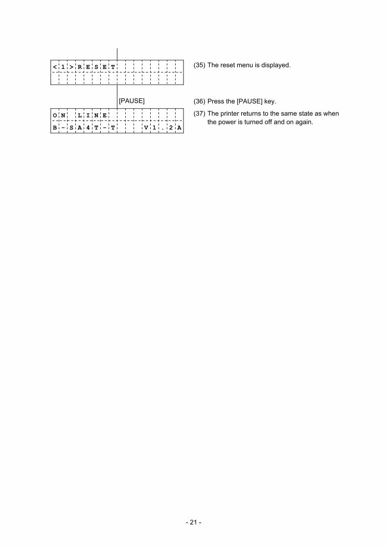
< 1 > R E S E T
(35) The reset menu is displayed.
[PAUSE] (36) Press the [PAUSE] key.
O N L I N E
B - S A 4 T - T V 1 . 2 A
(37) The printer returns to the same state as when the power is turned off and on again.
- 22 -
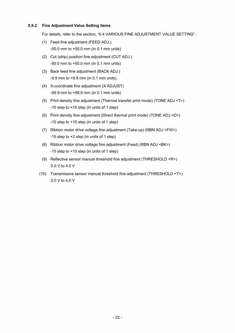
5.9.2 Fine Adjustment Value Setting Items
For details, refer to the section, “6.4 VARIOUS FINE ADJUSTMENT VALUE SETTING”.
(1) Feed fine adjustment (FEED ADJ.)
-50.0 mm to +50.0 mm (in 0.1 mm units)
(2) Cut (strip) position fine adjustment (CUT ADJ.)
-50.0 mm to +50.0 mm (in 0.1 mm units)
(3) Back feed fine adjustment (BACK ADJ.)
-9.9 mm to +9.9 mm (in 0.1 mm units)
(4) X-coordinate fine adjustment (X ADJUST)
-99.9 mm to +99.9 mm (in 0.1 mm units)
(5) Print density fine adjustment (Thermal transfer print mode) (TONE ADJ.<T>)
-10 step to +10 step (in units of 1 step)
(6) Print density fine adjustment (Direct thermal print mode) (TONE ADJ.<D>)
-10 step to +10 step (in units of 1 step)
(7) Ribbon motor drive voltage fine adjustment (Take-up) (RBN ADJ <FW>)
-15 step to +2 step (in units of 1 step)
(8) Ribbon motor drive voltage fine adjustment (Feed) (RBN ADJ <BK>)
-15 step to +10 step (in units of 1 step)
(9) Reflective sensor manual threshold fine adjustment (THRESHOLD <R>)
0.0 V to 4.0 V
(10) Transmissive sensor manual threshold fine adjustment (THRESHOLD <T>)
0.0 V to 4.0 V
- 23 -
5.10 DUMPING OF RECEIVE BUFFER
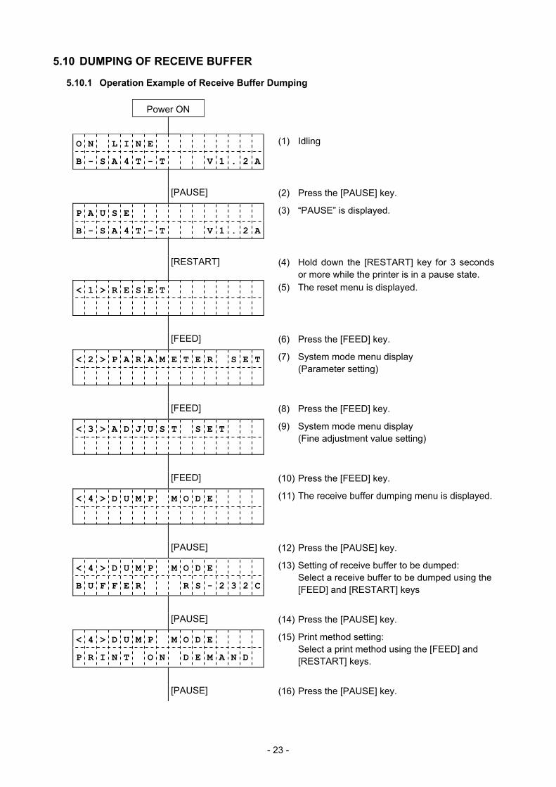
5.10.1 Operation Example of Receive Buffer Dumping
Power ON
O N L I N E (1) Idling
B - S A 4 T - T V 1 . 2 A
[PAUSE] (2) Press the [PAUSE] key.
P A U S E (3) “PAUSE” is displayed.
B - S A 4 T - T V 1 . 2 A
[RESTART] (4) Hold down the [RESTART] key for 3 seconds or more while the printer is in a pause state.
< 1 > R E S E T (5) The reset menu is displayed.
[FEED] (6) Press the [FEED] key.
< 2 > P A R A M E T E R S E T
(7) System mode menu display (Parameter setting)
[FEED] (8) Press the [FEED] key.
< 3 > A D J U S T S E T
(9) System mode menu display (Fine adjustment value setting)
[FEED] (10) Press the [FEED] key.
< 4 > D U M P M O D E
(11) The receive buffer dumping menu is displayed.
[PAUSE] (12) Press the [PAUSE] key.
< 4 > D U M P M O D E
B U F F E R R S - 2 3 2 C
(13) Setting of receive buffer to be dumped: Select a receive buffer to be dumped using the
[FEED] and [RESTART] keys
[PAUSE] (14) Press the [PAUSE] key.
< 4 > D U M P M O D E
P R I N T O N D E M A N D
(15) Print method setting: Select a print method using the [FEED] and
[RESTART] keys.
[PAUSE] (16) Press the [PAUSE] key.
- 24 -
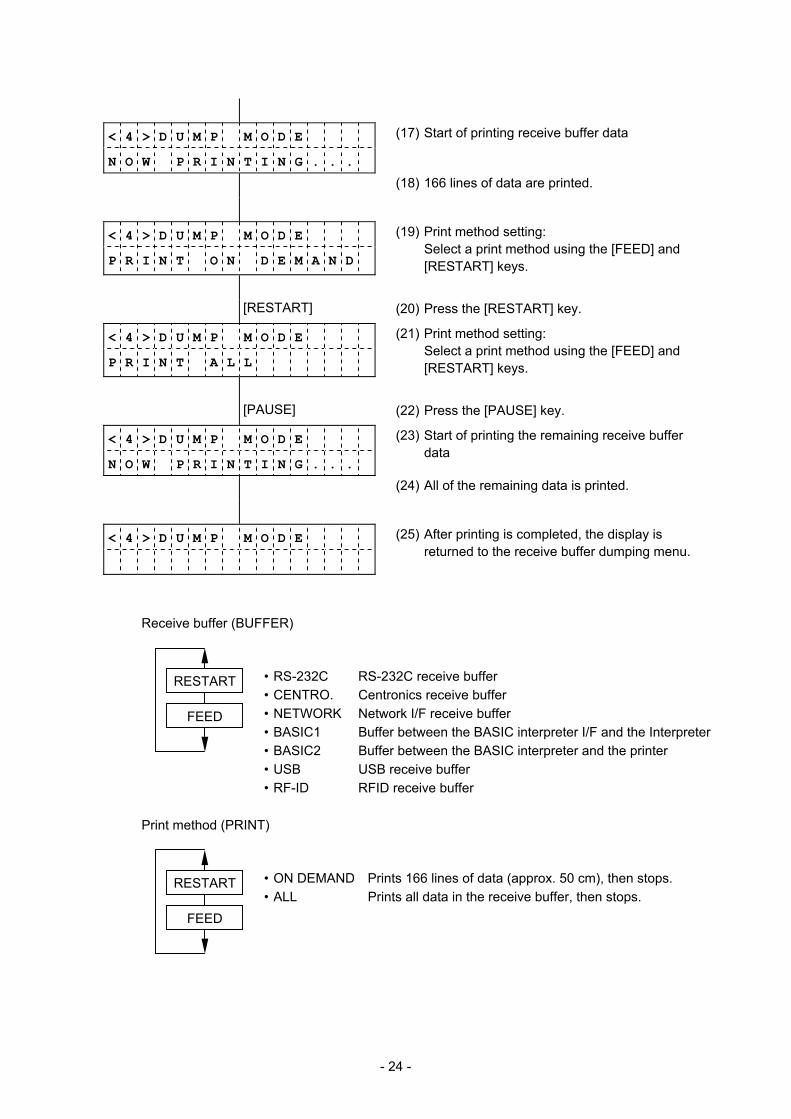
< 4 > D U M P M O D E
N O W P R I N T I N G . . .
(17) Start of printing receive buffer data
(18) 166 lines of data are printed.
< 4 > D U M P M O D E
P R I N T O N D E M A N D
(19) Print method setting: Select a print method using the [FEED] and
[RESTART] keys.
[RESTART] (20) Press the [RESTART] key.
< 4 > D U M P M O D E
P R I N T A L L
(21) Print method setting: Select a print method using the [FEED] and
[RESTART] keys.
[PAUSE] (22) Press the [PAUSE] key.
< 4 > D U M P M O D E
N O W P R I N T I N G . . .
(23) Start of printing the remaining receive buffer data
(24) All of the remaining data is printed.
< 4 > D U M P M O D E
(25) After printing is completed, the display is returned to the receive buffer dumping menu.
Receive buffer (BUFFER)
• RS-232C RS-232C receive buffer • CENTRO. Centronics receive buffer • NETWORK Network I/F receive buffer • BASIC1 Buffer between the BASIC interpreter I/F and the Interpreter • BASIC2 Buffer between the BASIC interpreter and the printer • USB USB receive buffer • RF-ID RFID receive buffer
Print method (PRINT)
• ON DEMAND Prints 166 lines of data (approx. 50 cm), then stops. • ALL Prints all data in the receive buffer, then stops.
FEED
RESTART
FEED
RESTART

- 25 -
Data in the receive buffer is printed in the format below.
Feed direction
00 00 00 00 00 00 00 00 00 00 00 00 00 00 00 00 ................
00 00 00 00 00 00 00 00 00 00 00 00 00 00 00 00 ................
00 00 00 00 00 00 00 00 00 00 00 00 00 00 00 00 ................
00 00 00 00 00 00 00 00 00 00 00 00 00 00 00 00 ................
7B 41 58 3B 2B 30 30 30 2C 2B 30 30 30 2C 2B 30 {AX;+000,+000,+0
30 7C 7D 7B 44 30 37 37 30 2C 31 31 30 30 2C 30 0|}{D0760,1100,0
37 34 30 7C 7D 7B 43 7C 7D 7B 4C 43 3B 30 30 33 740|}{C|}{LC;003
30 2C 30 30 32 30 2C 30 30 33 30 2C 30 36 36 30 0,0020,0030,0660
2C 30 2C 32 7C 7D 7B 4C 43 3B 30 30 37 30 2C 30 ,0,2|}{LC;0070,0
30 32 30 2C 30 30 37 30 2C 30 36 36 30 2C 30 2C 020,0070,0660,0,
39 7C 7D 7B 4C 43 3B 30 30 35 30 2C 30 30 32 30 9|}{LC;0050,0020
44 45 46 47 48 49 4A 7C 7D 7B 50 43 31 30 3B 30 DEFGHIJ|}{PC10;0
33 35 30 2C 30 34 30 30 2C 31 2C 31 2C 4B 2C 30 350,0400,1,1,K,0
30 2C 42 3D 41 42 43 44 65 66 67 68 69 6A 6B 6C 0,B=ABCDefghijkl
6D 6E 6F 70 7C 7D 7B 50 56 30 32 3B 30 33 33 30 mnop|}{PV02;0330
2C 30 36 36 30 2C 30 32 37 30 2C 30 32 35 30 2C ,0660,0270,0250,
41 2C 30 30 2C 42 3D 42 7C 7D 7B 50 56 30 33 3B A,00,B=B|}{PV03;
3B 30 39 30 30 2C 30 31 38 30 2C 54 2C 48 2C 30 ;0900,0180,T,H,0
35 2C 41 2C 30 3D 31 32 33 34 35 36 37 38 39 30 5,A,0=1234567890
41 42 43 44 45 7C 7D 00 00 00 00 00 00 00 00 00 ABCDE|}.........
- 26 -
Print conditions:
• Print width: Approximately 100 mm • Sensor: Not used • Print speed: 4 ips • A currently selected print mode (thermal transfer/direct thermal) is used.
• Data of 16 bytes is printed on one line.
• Data is printed, starting from new data to old data.
• Data pointed by a receive buffer write pointer is printed in bold type.
Size of receive buffer
RS-232C: 1 MB (Max. 65536 lines) Centronics: 1 MB (Max. 65536 lines) Network I/F: 1 MB (Max. 65536 lines) BASIC1: 8 KB (Max. 512 lines) BASIC2: 8 KB (Max. 512 lines) USB: 1 MB (Max. 65536 lines) RFID: 8 KB (Max. 512 lines)
NOTES:
1. To print all data in a receive buffer, the following label length is required.
RS-232C: 198.2 m Centronics: 198.2 m Network I/F: 198.2 m BASIC1: 2 m BASIC2: 2 m USB: 198.2 m RFID: 2 m
2. If an error occurs during printing in receive buffer dump mode, the printer displays an
error message, then stops. The error is cleared by pressing the [PAUSE] key, and the display is returned to the receive buffer dumping menu “<4> DUMP MODE”. After the error is cleared, data is not automatically reprinted.
5.11 BASIC EXPANSION MODE
It is possible to execute the BASIC expansion mode program in BASIC expansion mode under the following conditions: - The BASIC expansion mode program has already been loaded. - The BASIC enable setting mode is selected. The basic expansion mode ends when the basic expansion program is exited.
- 27 -
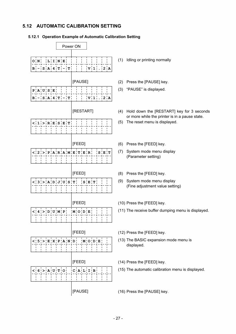
5.12 AUTOMATIC CALIBRATION SETTING
5.12.1 Operation Example of Automatic Calibration Setting
Power ON
O N L I N E (1) Idling or printing normally
B - S A 4 T - T V 1 . 2 A
[PAUSE] (2) Press the [PAUSE] key.
P A U S E (3) “PAUSE” is displayed.
B - S A 4 T - T V 1 . 2 A
[RESTART] (4) Hold down the [RESTART] key for 3 seconds or more while the printer is in a pause state.
< 1 > R E S E T (5) The reset menu is displayed.
[FEED] (6) Press the [FEED] key.
< 2 > P A R A M E T E R S E T
(7) System mode menu display (Parameter setting)
[FEED] (8) Press the [FEED] key.
< 3 > A D J U S T S E T
(9) System mode menu display (Fine adjustment value setting)
[FEED] (10) Press the [FEED] key.
< 4 > D U M P M O D E
(11) The receive buffer dumping menu is displayed.
[FEED] (12) Press the [FEED] key.
< 5 > E X P A N D M O D E
(13) The BASIC expansion mode menu is displayed.
[FEED] (14) Press the [FEED] key.
< 6 > A U T O C A L I B
(15) The automatic calibration menu is displayed.
[PAUSE] (16) Press the [PAUSE] key.
- 28 -
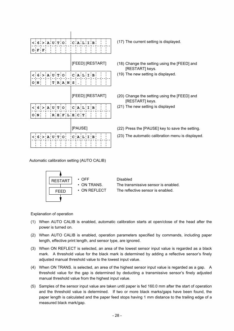
< 6 > A U T O C A L I B
O F F
(17) The current setting is displayed.
[FEED] [RESTART] (18) Change the setting using the [FEED] and [RESTART] keys.
< 6 > A U T O C A L I B
O N T R A N S .
(19) The new setting is displayed.
[FEED] [RESTART] (20) Change the setting using the [FEED] and [RESTART] keys.
< 6 > A U T O C A L I B
O N R E F L E C T
(21) The new setting is displayed
[PAUSE] (22) Press the [PAUSE] key to save the setting.
< 6 > A U T O C A L I B (23) The automatic calibration menu is displayed.
Automatic calibration setting (AUTO CALIB)
• OFF Disabled • ON TRANS. The transmissive sensor is enabled. • ON REFLECT The reflective sensor is enabled.
Explanation of operation
(1) When AUTO CALIB is enabled, automatic calibration starts at open/close of the head after the power is turned on.
(2) When AUTO CALIB is enabled, operation parameters specified by commands, including paper length, effective print length, and sensor type, are ignored.
(3) When ON REFLECT is selected, an area of the lowest sensor input value is regarded as a black mark. A threshold value for the black mark is determined by adding a reflective sensor’s finely adjusted manual threshold value to the lowest input value.
(4) When ON TRANS. is selected, an area of the highest sensor input value is regarded as a gap. A threshold value for the gap is determined by deducting a transmissive sensor’s finely adjusted manual threshold value from the highest input value.
(5) Samples of the sensor input value are taken until paper is fed 160.0 mm after the start of operation and the threshold value is determined. If two or more black marks/gaps have been found, the paper length is calculated and the paper feed stops having 1 mm distance to the trailing edge of a measured black mark/gap.
FEED
RESTART
- 29 -
(6) If the second black mark/gap has not been found under the above conditions, the paper feed continues. If the second black mark/gap is not found even after paper is fed at a maximum of 1,000.0 mm, it is regarded as a paper feed jam and the paper feed stops.
(7) Paper pitch to be supported is 10.0 mm to 355.6 (14 inches) mm.
(8) When the cutter is installed and a previous issue was performed in cut issue mode, paper is cut and ejected after automatic calibration completes.
(9) When the automatic calibration is in operation, paper does not stop at a strip position even in strip or special strip mode.
(10) When the automatic calibration is in operation, labels do not stop at a strip position even in strip or special strip mode. (Labels stop at the strip position when the firmware version is C2.0D or later.)
(11) When the automatic calibration is in operation, a label end error or head open error causes the printer to stop. Opening the head can clear the error and the automatic calibration resumes.
(12) Whenever the automatic calibration is in operation, the ribbon is driven. Even when a no ribbon state is detected, it does not cause a ribbon error. No ribbon is included in the operation conditions after the automatic calibration completes.
- 30 -
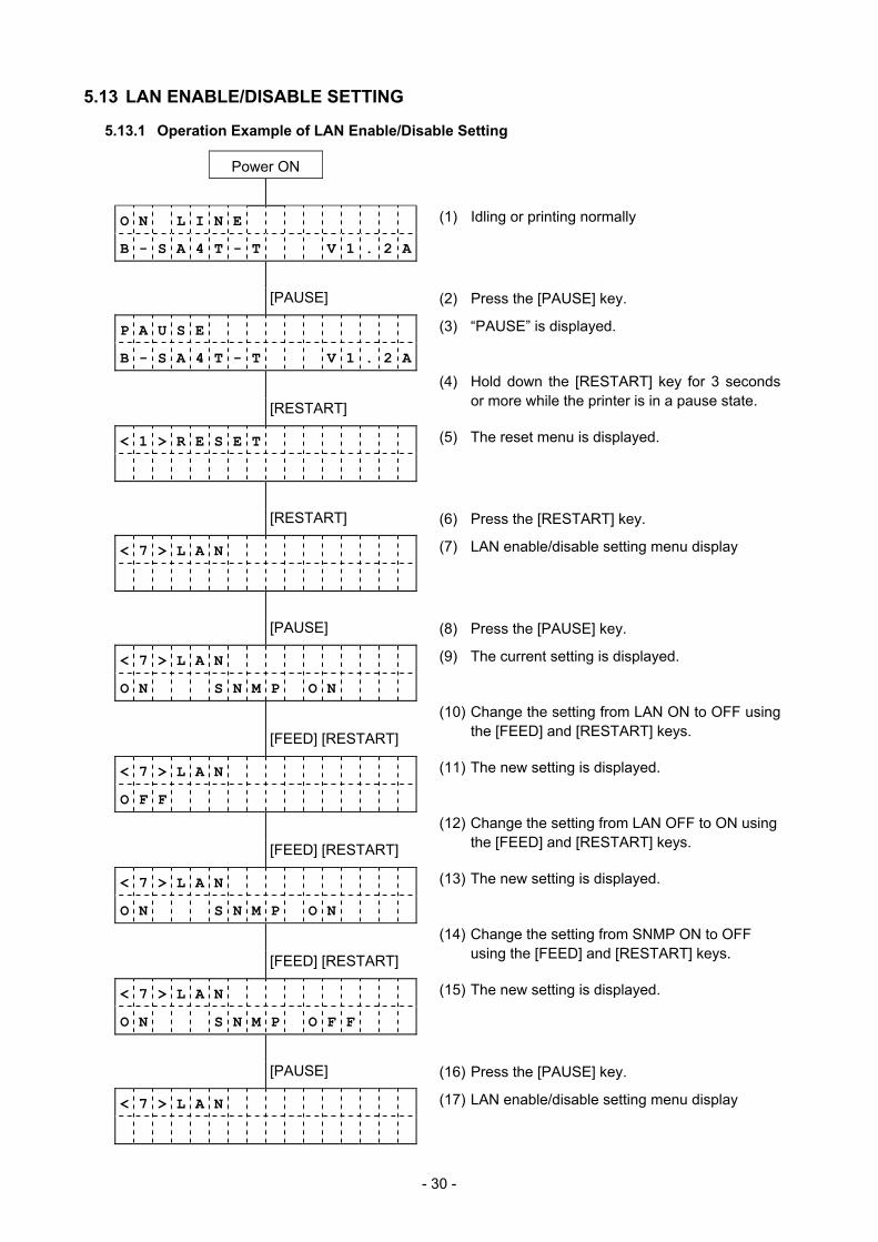
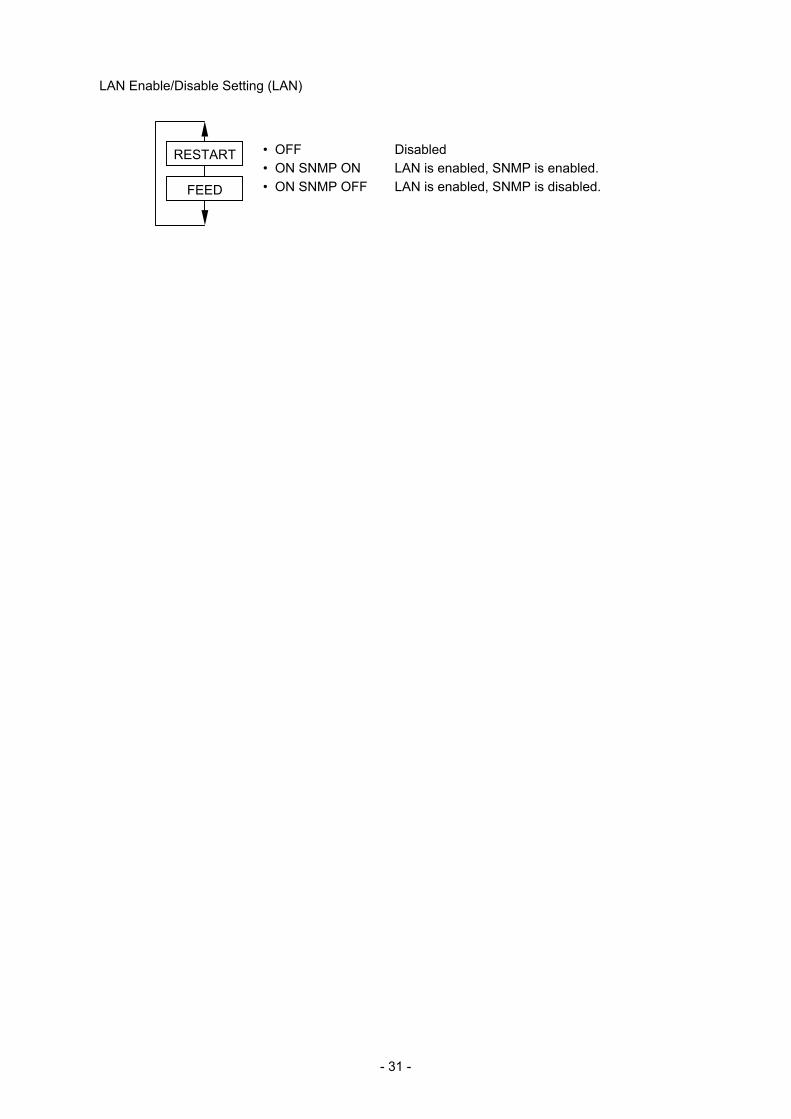
5.13 LAN ENABLE/DISABLE SETTING
5.13.1 Operation Example of LAN Enable/Disable Setting
Power ON
O N L I N E (1) Idling or printing normally
B - S A 4 T - T V 1 . 2 A
[PAUSE] (2) Press the [PAUSE] key.
P A U S E (3) “PAUSE” is displayed.
B - S A 4 T - T V 1 . 2 A
[RESTART]
(4) Hold down the [RESTART] key for 3 seconds or more while the printer is in a pause state.
< 1 > R E S E T (5) The reset menu is displayed.
[RESTART] (6) Press the [RESTART] key.
< 7 > L A N
(7) LAN enable/disable setting menu display
[PAUSE] (8) Press the [PAUSE] key.
< 7 > L A N
O N S N M P O N
(9) The current setting is displayed.
[FEED] [RESTART]
(10) Change the setting from LAN ON to OFF using the [FEED] and [RESTART] keys.
< 7 > L A N
O F F
(11) The new setting is displayed.
[FEED] [RESTART]
(12) Change the setting from LAN OFF to ON using the [FEED] and [RESTART] keys.
< 7 > L A N
O N S N M P O N
(13) The new setting is displayed.
[FEED] [RESTART]
(14) Change the setting from SNMP ON to OFF using the [FEED] and [RESTART] keys.
< 7 > L A N
O N S N M P O F F
(15) The new setting is displayed.
[PAUSE] (16) Press the [PAUSE] key.
< 7 > L A N (17) LAN enable/disable setting menu display
- 31 -
LAN Enable/Disable Setting (LAN)
• OFF Disabled • ON SNMP ON LAN is enabled, SNMP is enabled. • ON SNMP OFF LAN is enabled, SNMP is disabled.
FEED
RESTART
- 32 -
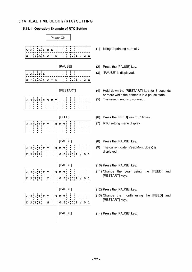
5.14 REAL TIME CLOCK (RTC) SETTING
5.14.1 Operation Example of RTC Setting
Power ON
O N L I N E (1) Idling or printing normally
B - S A 4 T - T V 1 . 2 A
[PAUSE] (2) Press the [PAUSE] key.
P A U S E (3) “PAUSE” is displayed.
B - S A 4 T - T V 1 . 2 A
[RESTART] (4) Hold down the [RESTART] key for 3 seconds or more while the printer is in a pause state.
< 1 > R E S E T (5) The reset menu is displayed.
[FEED] (6) Press the [FEED] key for 7 times.
< 8 > R T C S E T
(7) RTC setting menu display
[PAUSE] (8) Press the [PAUSE] key.
< 8 > R T C S E T
D A T E 0 5 / 0 1 / 0 1
(9) The current date (Year/Month/Day) is displayed.
[PAUSE] (10) Press the [PAUSE] key.
< 8 > R T C S E T
D A T E Y 0 5 / 0 1 / 0 1
(11) Change the year using the [FEED] and [RESTART] keys.
[PAUSE] (12) Press the [PAUSE] key.
< 8 > R T C S E T
D A T E M 0 6 / 0 1 / 0 1
(13) Change the month using the [FEED] and [RESTART] keys.
[PAUSE] (14) Press the [PAUSE] key.
- 33 -
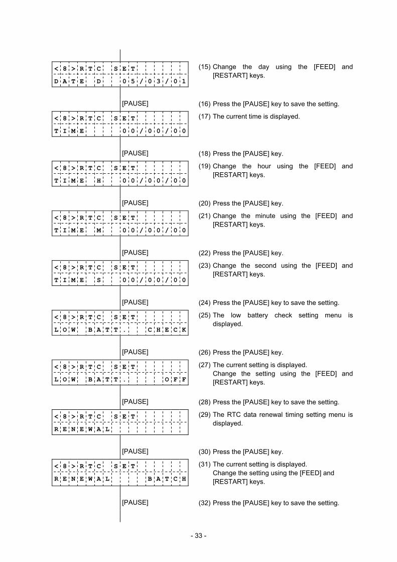
< 8 > R T C S E T
D A T E D 0 5 / 0 3 / 0 1
(15) Change the day using the [FEED] and [RESTART] keys.
[PAUSE] (16) Press the [PAUSE] key to save the setting.
< 8 > R T C S E T
T I M E 0 0 / 0 0 / 0 0
(17) The current time is displayed.
[PAUSE] (18) Press the [PAUSE] key.
< 8 > R T C S E T
T I M E H 0 0 / 0 0 / 0 0
(19) Change the hour using the [FEED] and [RESTART] keys.
[PAUSE] (20) Press the [PAUSE] key.
< 8 > R T C S E T
T I M E M 0 0 / 0 0 / 0 0
(21) Change the minute using the [FEED] and [RESTART] keys.
[PAUSE] (22) Press the [PAUSE] key.
< 8 > R T C S E T
T I M E S 0 0 / 0 0 / 0 0
(23) Change the second using the [FEED] and [RESTART] keys.
[PAUSE] (24) Press the [PAUSE] key to save the setting.
< 8 > R T C S E T
L O W B A T T . C H E C K
(25) The low battery check setting menu is displayed.
[PAUSE] (26) Press the [PAUSE] key.
< 8 > R T C S E T
L O W B A T T . O F F
(27) The current setting is displayed. Change the setting using the [FEED] and [RESTART] keys.
[PAUSE] (28) Press the [PAUSE] key to save the setting.
< 8 > R T C S E T
R E N E W A L
(29) The RTC data renewal timing setting menu is displayed.
[PAUSE] (30) Press the [PAUSE] key.
< 8 > R T C S E T
R E N E W A L B A T C H
(31) The current setting is displayed. Change the setting using the [FEED] and [RESTART] keys.
[PAUSE] (32) Press the [PAUSE] key to save the setting.

- 34 -
< 8 > R T C S E T
D A T E 0 6 / 0 3 / 0 1
(33) The current date is displayed.
[FEED] [RESTART] (34) Press the [FEED] and [RESTART] keys.
< 8 > R T C S E T
(35) The RTC setting menu is displayed.
RTC low battery check (LOWBATT. CHECK)
• OFF Disabled • ON Enabled
RTC data renewal timing (RENEWAL)
• BATCH Per batch • PAGE Per page
NOTES: • Be sure to load the battery whenever the RTC data is used. • If the battery is not loaded or the battery voltage is low, the RTC data is erased at the power off time. • When the low battery check function is set to ON, the printer stops at the power on time due to a
“LOW BATTERY” error if the battery voltage is 1.9V or less. As a restart is invalidated in this case, hold down the [RESTART] key to cause the printer to enter <1>RESET mode, access the Real Time Clock setting mode, and set the low battery function to OFF.
• The factory setting for the low battery check function is OFF. • To enable the real time clock function, set the low battery check to ON. • When the low battery check is set to OFF, the RTC function is available even in a low battery state.
However, the setting and check of the real time clock is required whenever the power is turned on. • When the RTC data renewal timing is set to “PAGE”, the printer stops between labels ignoring the on-
the-fly issue even when an Issue command is sent to print more than one label.
FEED
RESTART
FEED
RESTART
- 35 -
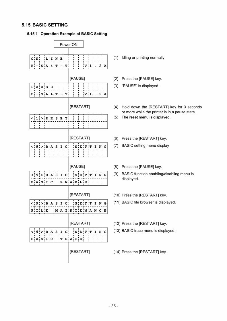
5.15 BASIC SETTING
5.15.1 Operation Example of BASIC Setting
Power ON
O N L I N E (1) Idling or printing normally
B - S A 4 T - T V 1 . 2 A
[PAUSE] (2) Press the [PAUSE] key.
P A U S E (3) “PAUSE” is displayed.
B - S A 4 T - T V 1 . 2 A
[RESTART] (4) Hold down the [RESTART] key for 3 seconds or more while the printer is in a pause state.
< 1 > R E S E T (5) The reset menu is displayed.
[RESTART] (6) Press the [RESTART] key.
< 9 > B A S I C S E T T I N G
(7) BASIC setting menu display
[PAUSE] (8) Press the [PAUSE] key.
< 9 > B A S I C S E T T I N G
B A S I C E N A B L E
(9) BASIC function enabling/disabling menu is displayed.
[RESTART] (10) Press the [RESTART] key.
< 9 > B A S I C S E T T I N G
F I L E M A I N T E N A N C E
(11) BASIC file browser is displayed.
[RESTART] (12) Press the [RESTART] key.
< 9 > B A S I C S E T T I N G
B A S I C T R A C E
(13) BASIC trace menu is displayed.
[RESTART] (14) Press the [RESTART] key.

- 36 -
< 9 > B A S I C S E T T I N G
E X P A N D M O D E
(15) BASIC expansion menu is displayed.
[RESTART] (16) Press the [RESTART] key.
< 9 > B A S I C S E T T I N G
B A S I C E N A B L E
(17) BASIC function enable/disable setting menu is displayed.
[PAUSE] (18) Press the [PAUSE] key.
< 9 > B A S I C S E T T I N G
B A S I C O F F
(19) BASIC function is disabled.
[FEED] (20) Press the [FEED] key.
< 9 > B A S I C S E T T I N G
B A S I C O N
(21) BASIC function is enabled.
[PAUSE] (22) Press the [PAUSE] key.
< 9 > B A S I C S E T T I N G
F I L E M A I N T E N A N C E
(23) BASIC file browser is displayed.
[PAUSE] (24) Press the [PAUSE] key to save the setting.
< 9 > B A S I C S E T T I N G
0 0 T E S T . B A S
(25) Program file is displayed.
[RESTART] (26) Press the [RESTART] key.
< 9 > B A S I C S E T T I N G
0 1 T E S T . D A T
(27) Data file is displayed.
(28) Names of data files in the BASIC file area are
displayed.
< 9 > B A S I C S E T T I N G
0 0 T E S T . B A S
(29) Program file is displayed.
[PAUSE] (30) Press the [PAUSE] key.
< 9 > B A S I C S E T T I N G
B A S I C T R A C E
(31) BASIC trace menu is displayed.
[PAUSE] (32) Press the [PAUSE] key.
- 37 -
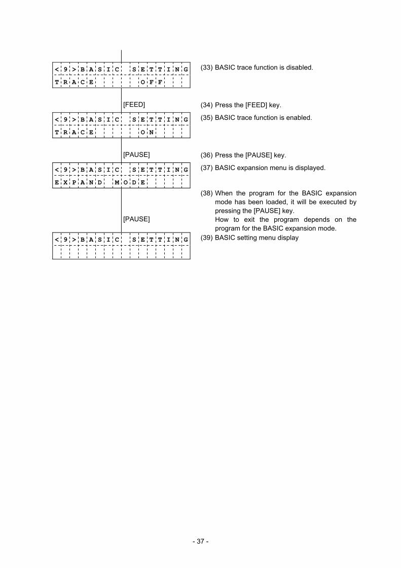
< 9 > B A S I C S E T T I N G
T R A C E O F F
(33) BASIC trace function is disabled.
[FEED] (34) Press the [FEED] key.
< 9 > B A S I C S E T T I N G
T R A C E O N
(35) BASIC trace function is enabled.
[PAUSE] (36) Press the [PAUSE] key.
< 9 > B A S I C S E T T I N G
E X P A N D M O D E
(37) BASIC expansion menu is displayed.
(38) When the program for the BASIC expansion mode has been loaded, it will be executed by pressing the [PAUSE] key.
[PAUSE] How to exit the program depends on the program for the BASIC expansion mode.
< 9 > B A S I C S E T T I N G
(39) BASIC setting menu display
- 38 -
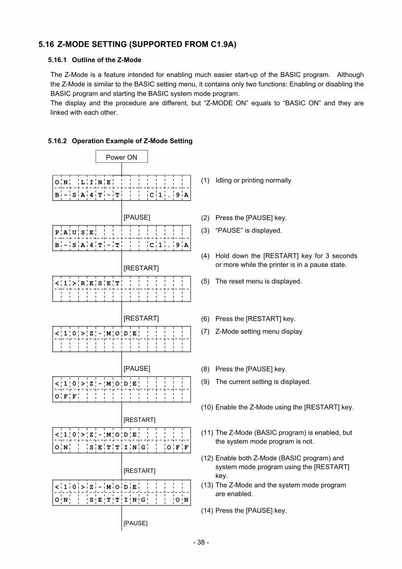
5.16 Z-MODE SETTING (SUPPORTED FROM C1.9A)
5.16.1 Outline of the Z-Mode
The Z-Mode is a feature intended for enabling much easier start-up of the BASIC program. Although the Z-Mode is similar to the BASIC setting menu, it contains only two functions: Enabling or disabling the BASIC program and starting the BASIC system mode program. The display and the procedure are different, but “Z-MODE ON” equals to “BASIC ON” and they are linked with each other.
5.16.2 Operation Example of Z-Mode Setting
Power ON
O N L I N E (1) Idling or printing normally
B - S A 4 T - T C 1 . 9 A
[PAUSE] (2) Press the [PAUSE] key.
P A U S E (3) “PAUSE” is displayed.
B - S A 4 T - T C 1 . 9 A
[RESTART]
(4) Hold down the [RESTART] key for 3 seconds or more while the printer is in a pause state.
< 1 > R E S E T (5) The reset menu is displayed.
[RESTART] (6) Press the [RESTART] key.
< 1 0 > Z - M O D E
(7) Z-Mode setting menu display
[PAUSE] (8) Press the [PAUSE] key.
< 1 0 > Z - M O D E
O F F
(9) The current setting is displayed.
[RESTART]
(10) Enable the Z-Mode using the [RESTART] key.
< 1 0 > Z - M O D E
O N S E T T I N G O F F
(11) The Z-Mode (BASIC program) is enabled, but the system mode program is not.
[RESTART]
(12) Enable both Z-Mode (BASIC program) and system mode program using the [RESTART] key.
< 1 0 > Z - M O D E
O N S E T T I N G O N
(13) The Z-Mode and the system mode program are enabled.
[PAUSE]
(14) Press the [PAUSE] key.
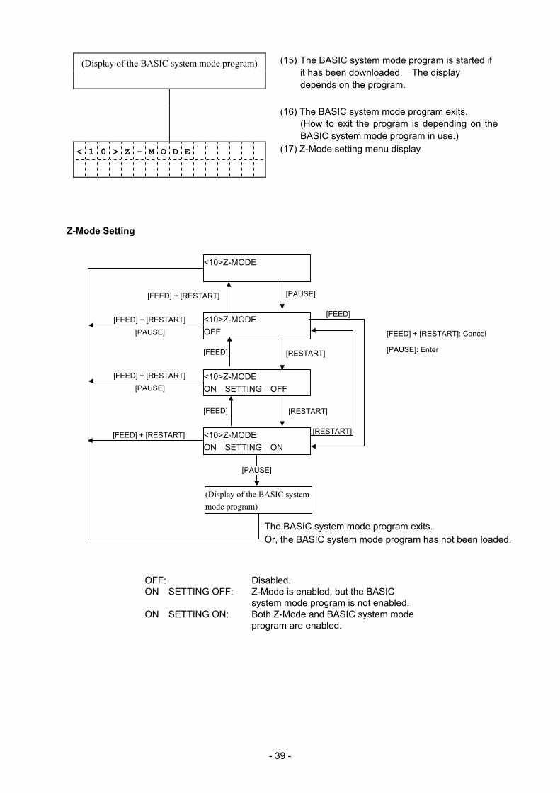
- 39 -
(Display of the BASIC system mode program)
(15) The BASIC system mode program is started if it has been downloaded. The display depends on the program.
(16) The BASIC system mode program exits. (How to exit the program is depending on the BASIC system mode program in use.)
< 1 0 > Z - M O D E
(17) Z-Mode setting menu display
Z-Mode Setting
<10>Z-MODE OFF
<10>Z-MODE ON SETTING OFF
OFF: Disabled. ON SETTING OFF: Z-Mode is enabled, but the BASIC
system mode program is not enabled. ON SETTING ON: Both Z-Mode and BASIC system mode
program are enabled.
[PAUSE]
[RESTART]
[RESTART]
<10>Z-MODE ON SETTING ON
[PAUSE]
(Display of the BASIC system mode program)
The BASIC system mode program exits. Or, the BASIC system mode program has not been loaded.
<10>Z-MODE
[FEED] + [RESTART]
[PAUSE][FEED] + [RESTART]
[RESTART]
[FEED]
[FEED]
[PAUSE][FEED] + [RESTART]
[FEED] + [RESTART]
[FEED]
[FEED] + [RESTART]: Cancel
[PAUSE]: Enter
- 40 -
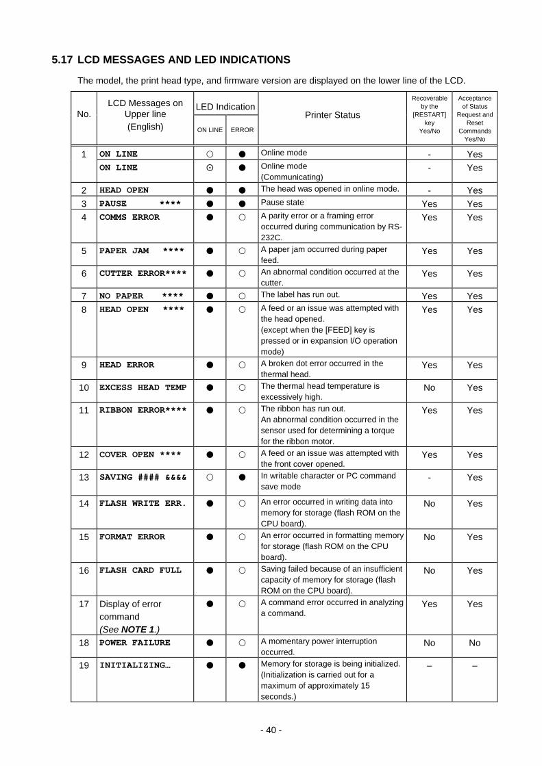
5.17 LCD MESSAGES AND LED INDICATIONS
The model, the print head type, and firmware version are displayed on the lower line of the LCD.
No. LCD Messages on
Upper line (English)
LED Indication
Printer Status
Recoverable by the
[RESTART] key
Yes/No
Acceptance of Status
Request and Reset
CommandsYes/No
ON LINE ERROR
1 ON LINE Online mode - Yes ON LINE Online mode
(Communicating) - Yes
2 HEAD OPEN The head was opened in online mode. - Yes 3 PAUSE **** Pause state Yes Yes 4 COMMS ERROR A parity error or a framing error
occurred during communication by RS-232C.
Yes Yes
5 PAPER JAM **** A paper jam occurred during paper feed.
Yes Yes
6 CUTTER ERROR**** An abnormal condition occurred at the cutter.
Yes Yes
7 NO PAPER **** The label has run out. Yes Yes 8 HEAD OPEN **** A feed or an issue was attempted with
the head opened. (except when the [FEED] key is pressed or in expansion I/O operation mode)
Yes Yes
9 HEAD ERROR A broken dot error occurred in the thermal head.
Yes Yes
10 EXCESS HEAD TEMP The thermal head temperature is excessively high.
No Yes
11 RIBBON ERROR**** The ribbon has run out. An abnormal condition occurred in the sensor used for determining a torque for the ribbon motor.
Yes Yes
12 COVER OPEN **** A feed or an issue was attempted with the front cover opened.
Yes Yes
13 SAVING #### &&&&
In writable character or PC command save mode
- Yes
14 FLASH WRITE ERR. An error occurred in writing data into memory for storage (flash ROM on the CPU board).
No Yes
15 FORMAT ERROR An error occurred in formatting memory for storage (flash ROM on the CPU board).
No Yes
16 FLASH CARD FULL Saving failed because of an insufficient capacity of memory for storage (flash ROM on the CPU board).
No Yes
17 Display of error command (See NOTE 1.)
A command error occurred in analyzing a command.
Yes Yes
18 POWER FAILURE A momentary power interruption occurred.
No No
19 INITIALIZING… Memory for storage is being initialized. (Initialization is carried out for a maximum of approximately 15 seconds.)
– –
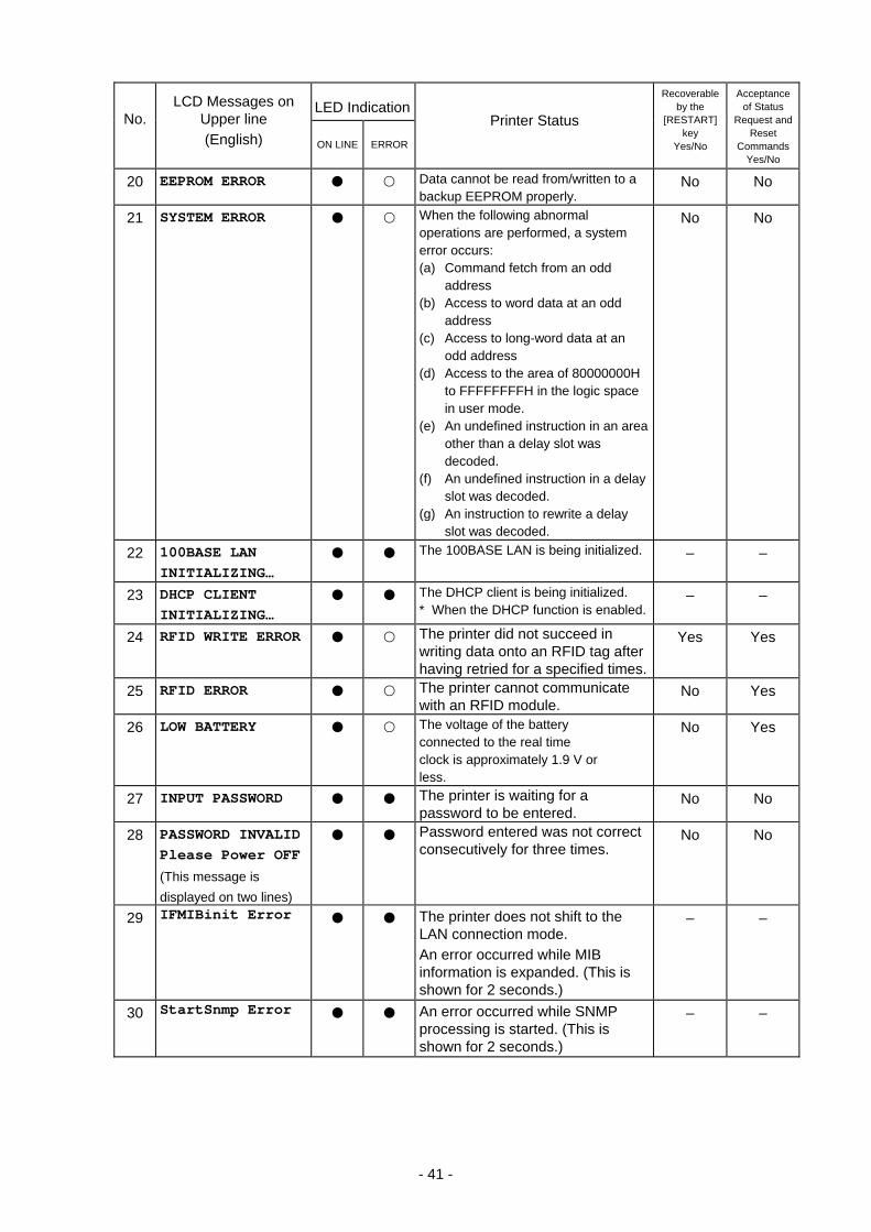
- 41 -
No. LCD Messages on
Upper line (English)
LED Indication
Printer Status
Recoverable by the
[RESTART] key
Yes/No
Acceptance of Status
Request and Reset
CommandsYes/No
ON LINE ERROR
20 EEPROM ERROR Data cannot be read from/written to a backup EEPROM properly.
No No
21 SYSTEM ERROR When the following abnormal operations are performed, a system error occurs: (a) Command fetch from an odd
address (b) Access to word data at an odd
address (c) Access to long-word data at an
odd address (d) Access to the area of 80000000H
to FFFFFFFFH in the logic space in user mode.
(e) An undefined instruction in an area other than a delay slot was decoded.
(f) An undefined instruction in a delay slot was decoded.
(g) An instruction to rewrite a delay slot was decoded.
No No
22 100BASE LAN INITIALIZING…
The 100BASE LAN is being initialized. – –
23 DHCP CLIENT INITIALIZING…
The DHCP client is being initialized. * When the DHCP function is enabled.
– –
24 RFID WRITE ERROR The printer did not succeed in writing data onto an RFID tag after having retried for a specified times.
Yes Yes
25 RFID ERROR The printer cannot communicate with an RFID module.
No Yes
26 LOW BATTERY The voltage of the battery connected to the real time clock is approximately 1.9 V or less.
No Yes
27 INPUT PASSWORD The printer is waiting for a password to be entered.
No No
28 PASSWORD INVALID Please Power OFF
(This message is displayed on two lines)
Password entered was not correct consecutively for three times.
No No
29 IFMIBinit Error The printer does not shift to the LAN connection mode. An error occurred while MIB information is expanded. (This is shown for 2 seconds.)
– –
30 StartSnmp Error An error occurred while SNMP processing is started. (This is shown for 2 seconds.)
– –

- 42 -
NOTE 1: When a command produces an error, 16 bytes of the command code of the erroneous command are displayed on the upper line of the LCD. (However, [LF] and [NUL] are not displayed.) [Example 1] [ESC] PC001; 0A00, 0300, 2, 2, A, 00, B [LF] [NUL]
Command error LCD display PC001;0A00,0300,
B-SA4T-T V1.2A
[Example 2] [ESC] T20 G30 [LF] [NUL]
Command error LCD display T20G30 B-SA4T-T V1.2A
[Example 3] [ESC] XR; 0200, 0300, 0450, 1200, 1 [LF] [NUL]
Command error LCD display XR;0200,0300,045
B-SA4T-T V1.2A
NOTE 2: When a command error is displayed, “? (3FH)” is displayed for codes other than 20H to 7FH and A0H to DFH.
NOTE 3: : ON : Blinking : OFF
****: Number of remaining labels to be printed to 9999 (in units of 1 label/tag) ###: Remaining memory capacity of PC save area of a flash memory on the CPU:
0 to 3072 (in K bytes) &&&&: Remaining memory capacity of writable character storage area for a flash memory on the
CPU 0 to 3072 (in K bytes)
NOTE 4: When a ribbon near end detection setting is enabled, the ERROR LED blinks slowly, while the printer is in a ribbon near end state and displays a message 1, 2, or 3.
- 43 -
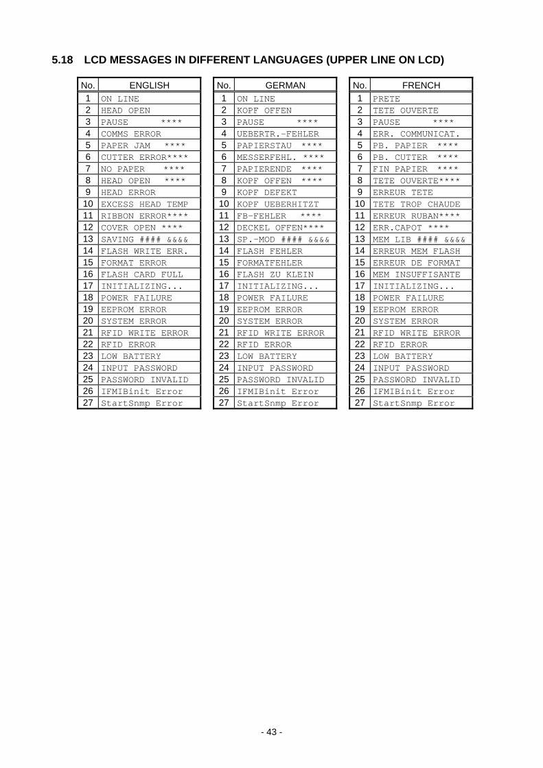
5.18 LCD MESSAGES IN DIFFERENT LANGUAGES (UPPER LINE ON LCD)
No. ENGLISH No. GERMAN No. FRENCH 1 ON LINE 1 ON LINE 1 PRETE 2 HEAD OPEN 2 KOPF OFFEN 2 TETE OUVERTE 3 PAUSE **** 3 PAUSE **** 3 PAUSE ****4 COMMS ERROR 4 UEBERTR.-FEHLER 4 ERR. COMMUNICAT.5 PAPER JAM **** 5 PAPIERSTAU **** 5 PB. PAPIER ****6 CUTTER ERROR**** 6 MESSERFEHL. **** 6 PB. CUTTER ****7 NO PAPER **** 7 PAPIERENDE **** 7 FIN PAPIER ****8 HEAD OPEN **** 8 KOPF OFFEN **** 8 TETE OUVERTE****9 HEAD ERROR 9 KOPF DEFEKT 9 ERREUR TETE
10 EXCESS HEAD TEMP 10 KOPF UEBERHITZT 10 TETE TROP CHAUDE11 RIBBON ERROR**** 11 FB-FEHLER **** 11 ERREUR RUBAN****12 COVER OPEN **** 12 DECKEL OFFEN**** 12 ERR.CAPOT ****13 SAVING #### &&&& 13 SP.-MOD #### &&&& 13 MEM LIB #### &&&&14 FLASH WRITE ERR. 14 FLASH FEHLER 14 ERREUR MEM FLASH15 FORMAT ERROR 15 FORMATFEHLER 15 ERREUR DE FORMAT16 FLASH CARD FULL 16 FLASH ZU KLEIN 16 MEM INSUFFISANTE17 INITIALIZING... 17 INITIALIZING... 17 INITIALIZING...18 POWER FAILURE 18 POWER FAILURE 18 POWER FAILURE 19 EEPROM ERROR 19 EEPROM ERROR 19 EEPROM ERROR 20 SYSTEM ERROR 20 SYSTEM ERROR 20 SYSTEM ERROR 21 RFID WRITE ERROR 21 RFID WRITE ERROR 21 RFID WRITE ERROR22 RFID ERROR 22 RFID ERROR 22 RFID ERROR 23 LOW BATTERY 23 LOW BATTERY 23 LOW BATTERY 24 INPUT PASSWORD 24 INPUT PASSWORD 24 INPUT PASSWORD25 PASSWORD INVALID 25 PASSWORD INVALID 25 PASSWORD INVALID26 IFMIBinit Error 26 IFMIBinit Error 26 IFMIBinit Error27 StartSnmp Error 27 StartSnmp Error 27 StartSnmp Error
- 44 -
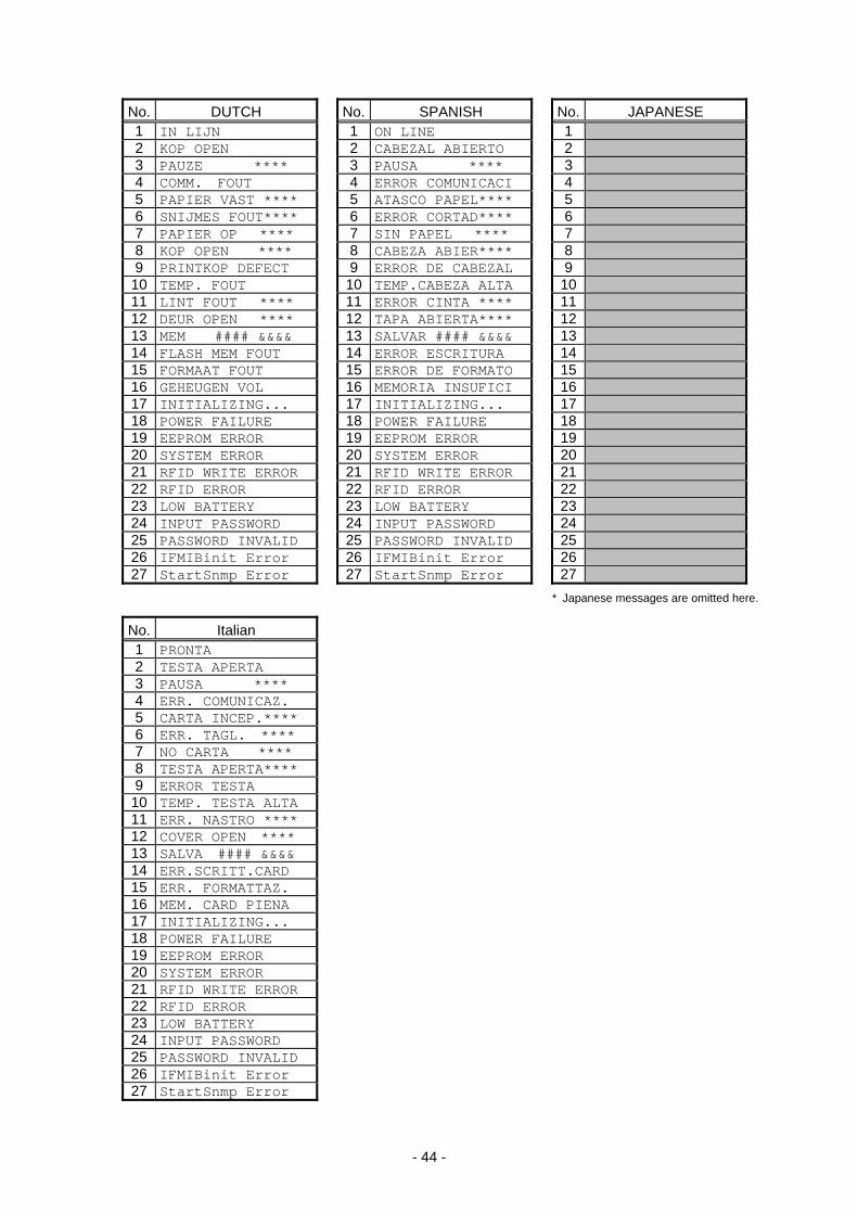
No. DUTCH No. SPANISH No. JAPANESE 1 IN LIJN 1 ON LINE 12 KOP OPEN 2 CABEZAL ABIERTO 23 PAUZE **** 3 PAUSA **** 34 COMM. FOUT 4 ERROR COMUNICACI 45 PAPIER VAST **** 5 ATASCO PAPEL**** 56 SNIJMES FOUT**** 6 ERROR CORTAD**** 67 PAPIER OP **** 7 SIN PAPEL **** 78 KOP OPEN **** 8 CABEZA ABIER**** 89 PRINTKOP DEFECT 9 ERROR DE CABEZAL 9
10 TEMP. FOUT 10 TEMP.CABEZA ALTA 1011 LINT FOUT **** 11 ERROR CINTA **** 1112 DEUR OPEN **** 12 TAPA ABIERTA**** 1213 MEM #### &&&& 13 SALVAR #### &&&& 1314 FLASH MEM FOUT 14 ERROR ESCRITURA 1415 FORMAAT FOUT 15 ERROR DE FORMATO 1516 GEHEUGEN VOL 16 MEMORIA INSUFICI 1617 INITIALIZING... 17 INITIALIZING... 1718 POWER FAILURE 18 POWER FAILURE 1819 EEPROM ERROR 19 EEPROM ERROR 1920 SYSTEM ERROR 20 SYSTEM ERROR 2021 RFID WRITE ERROR 21 RFID WRITE ERROR 2122 RFID ERROR 22 RFID ERROR 2223 LOW BATTERY 23 LOW BATTERY 2324 INPUT PASSWORD 24 INPUT PASSWORD 2425 PASSWORD INVALID 25 PASSWORD INVALID 2526 IFMIBinit Error 26 IFMIBinit Error 2627 StartSnmp Error 27 StartSnmp Error 27
* Japanese messages are omitted here.
No. Italian 1 PRONTA 2 TESTA APERTA3 PAUSA **** 4 ERR. COMUNICAZ. 5 CARTA INCEP.**** 6 ERR. TAGL. **** 7 NO CARTA **** 8 TESTA APERTA**** 9 ERROR TESTA
10 TEMP. TESTA ALTA 11 ERR. NASTRO **** 12 COVER OPEN **** 13 SALVA #### &&&& 14 ERR.SCRITT.CARD 15 ERR. FORMATTAZ. 16 MEM. CARD PIENA 17 INITIALIZING... 18 POWER FAILURE 19 EEPROM ERROR20 SYSTEM ERROR21 RFID WRITE ERROR 22 RFID ERROR 23 LOW BATTERY24 INPUT PASSWORD 25 PASSWORD INVALID 26 IFMIBinit Error 27 StartSnmp Error
- 45 -
6. SYSTEM MODE
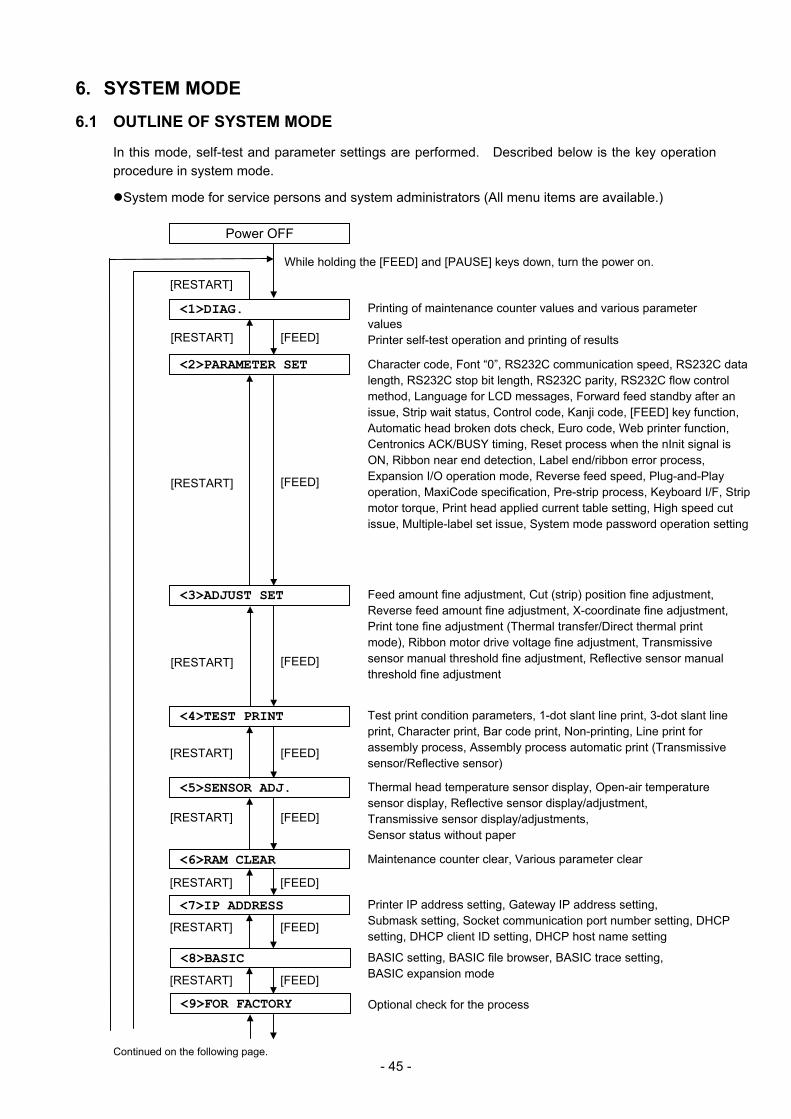
6.1 OUTLINE OF SYSTEM MODE
In this mode, self-test and parameter settings are performed. Described below is the key operation procedure in system mode.
System mode for service persons and system administrators (All menu items are available.)
While holding the [FEED] and [PAUSE] keys down, turn the power on.
Printing of maintenance counter values and various parameter values Printer self-test operation and printing of results
Character code, Font “0”, RS232C communication speed, RS232C data length, RS232C stop bit length, RS232C parity, RS232C flow control method, Language for LCD messages, Forward feed standby after an issue, Strip wait status, Control code, Kanji code, [FEED] key function, Automatic head broken dots check, Euro code, Web printer function, Centronics ACK/BUSY timing, Reset process when the nInit signal is ON, Ribbon near end detection, Label end/ribbon error process, Expansion I/O operation mode, Reverse feed speed, Plug-and-Play operation, MaxiCode specification, Pre-strip process, Keyboard I/F, Strip motor torque, Print head applied current table setting, High speed cut issue, Multiple-label set issue, System mode password operation setting
Feed amount fine adjustment, Cut (strip) position fine adjustment, Reverse feed amount fine adjustment, X-coordinate fine adjustment, Print tone fine adjustment (Thermal transfer/Direct thermal print mode), Ribbon motor drive voltage fine adjustment, Transmissive sensor manual threshold fine adjustment, Reflective sensor manual threshold fine adjustment
Power OFF
[RESTART]
[FEED] [RESTART]
[FEED] [RESTART]
[FEED] [RESTART]
[FEED] [RESTART]
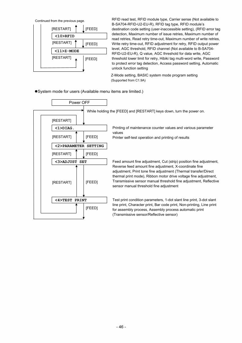
Test print condition parameters, 1-dot slant line print, 3-dot slant line print, Character print, Bar code print, Non-printing, Line print for assembly process, Assembly process automatic print (Transmissive sensor/Reflective sensor)
Thermal head temperature sensor display, Open-air temperature sensor display, Reflective sensor display/adjustment, Transmissive sensor display/adjustments, Sensor status without paper
<1>DIAG.
<2>PARAMETER SET
<3>ADJUST SET
Maintenance counter clear, Various parameter clear
<4>TEST PRINT
<5>SENSOR ADJ.
<6>RAM CLEAR
<7>IP ADDRESS Printer IP address setting, Gateway IP address setting, Submask setting, Socket communication port number setting, DHCP setting, DHCP client ID setting, DHCP host name setting
Optional check for the process
[FEED] [RESTART]
<8>BASIC
[FEED] [RESTART]
<9>FOR FACTORY
[FEED] [RESTART]
[FEED] [RESTART]
BASIC setting, BASIC file browser, BASIC trace setting, BASIC expansion mode
Continued on the following page.
- 46 -
System mode for users (Available menu items are limited.)
While holding the [FEED] and [RESTART] keys down, turn the power on.
Printing of maintenance counter values and various parameter values Printer self-test operation and printing of results
Feed amount fine adjustment, Cut (strip) position fine adjustment, Reverse feed amount fine adjustment, X-coordinate fine adjustment, Print tone fine adjustment (Thermal transfer/Direct thermal print mode), Ribbon motor drive voltage fine adjustment, Transmissive sensor manual threshold fine adjustment, Reflective sensor manual threshold fine adjustment
Power OFF
[RESTART]
[FEED] [RESTART]
[FEED] [RESTART]
[FEED]
Test print condition parameters, 1-dot slant line print, 3-dot slant line print, Character print, Bar code print, Non-printing, Line print for assembly process, Assembly process automatic print (Transmissive sensor/Reflective sensor)
<1>DIAG.
<3>ADJUST SET
<4>TEST PRINT
[FEED] [RESTART]
<2>PARAMETER SETTING
<10>RFID
[FEED]
[FEED] [RESTART]
RFID read test, RFID module type, Carrier sense (Not available to B-SA704-RFID-U2-EU-R), RFID tag type, RFID module’s destination code setting (user-inaccessible setting), (RFID error tag detection, Maximum number of issue retries, Maximum number of read retries, Read retry time-out, Maximum number of write retries, Write retry time-out, RFID adjustment for retry, RFID output power level, AGC threshold, RFID channel (Not available to B-SA704-RFID-U2-EU-R), Q value, AGC threshold for data write, AGC threshold lower limit for retry, Hibiki tag multi-word write, Password to protect error tag detection, Access password setting, Automatic unlock function setting
Continued from the previous page.
[RESTART]
<11>Z-MODE
[FEED] [RESTART]
Z-Mode setting, BASIC system mode program setting (Supported from C1.9A)
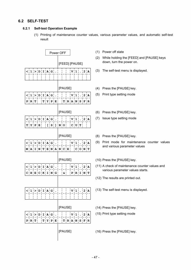
- 47 -
6.2 SELF-TEST
6.2.1 Self-test Operation Example
(1) Printing of maintenance counter values, various parameter values, and automatic self-test result
Power OFF (1) Power off state
[FEED] [PAUSE]
(2) While holding the [FEED] and [PAUSE] keys down, turn the power on.
< 1 > D I A G . V 1 . 2 A (3) The self-test menu is displayed.
[PAUSE] (4) Press the [PAUSE] key.
< 1 > D I A G . V 1 . 2 A
P R T T Y P E T R A N S F R
(5) Print type setting mode
[PAUSE] (6) Press the [PAUSE] key.
< 1 > D I A G . V 1 . 2 A
T Y P E [ S ] N O C U T
(7) Issue type setting mode
[PAUSE] (8) Press the [PAUSE] key.
< 1 > D I A G . V 1 . 2 A
M A I N T E N A N C E C O N T
(9) Print mode for maintenance counter values and various parameter values
[PAUSE] (10) Press the [PAUSE] key.
< 1 > D I A G . V 1 . 2 A
C H E C K I N G & P R I N T
(11) A check of maintenance counter values and various parameter values starts.
(12) The results are printed out.
< 1 > D I A G . V 1 . 2 A
(13) The self-test menu is displayed.
[PAUSE] (14) Press the [PAUSE] key.
< 1 > D I A G . V 1 . 2 A
P R T T Y P E T R A N S F R
(15) Print type setting mode
[PAUSE] (16) Press the [PAUSE] key.
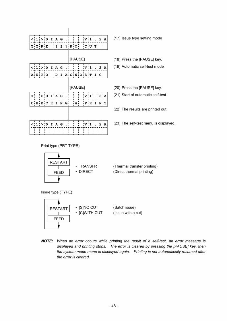
- 48 -
< 1 > D I A G . V 1 . 2 A
T Y P E [ S ] N O C U T
(17) Issue type setting mode
[PAUSE] (18) Press the [PAUSE] key.
< 1 > D I A G . V 1 . 2 A
A U T O D I A G N O S T I C
(19) Automatic self-test mode
[PAUSE] (20) Press the [PAUSE] key.
< 1 > D I A G . V 1 . 2 A
C H E C K I N G & P R I N T
(21) Start of automatic self-test
(22) The results are printed out.
< 1 > D I A G . V 1 . 2 A
(23) The self-test menu is displayed.
Print type (PRT TYPE)
• TRANSFR (Thermal transfer printing) • DIRECT (Direct thermal printing)
Issue type (TYPE)
• [S]NO CUT (Batch issue) • [C]WITH CUT (Issue with a cut)
NOTE: When an error occurs while printing the result of a self-test, an error message is displayed and printing stops. The error is cleared by pressing the [PAUSE] key, then the system mode menu is displayed again. Printing is not automatically resumed after the error is cleared.
FEED
RESTART
FEED
RESTART
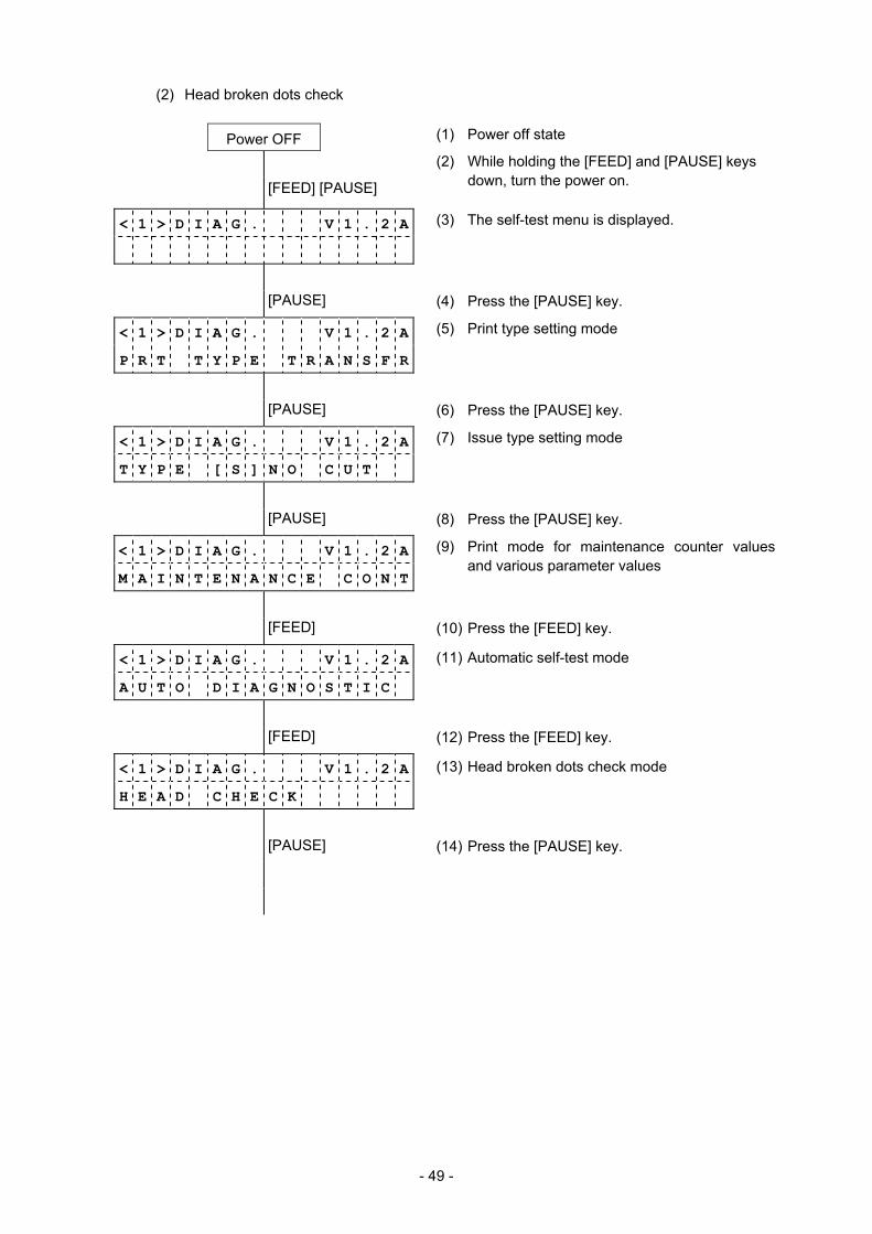
- 49 -
(2) Head broken dots check
Power OFF (1) Power off state
[FEED] [PAUSE]
(2) While holding the [FEED] and [PAUSE] keys down, turn the power on.
< 1 > D I A G . V 1 . 2 A (3) The self-test menu is displayed.
[PAUSE] (4) Press the [PAUSE] key.
< 1 > D I A G . V 1 . 2 A
P R T T Y P E T R A N S F R
(5) Print type setting mode
[PAUSE] (6) Press the [PAUSE] key.
< 1 > D I A G . V 1 . 2 A
T Y P E [ S ] N O C U T
(7) Issue type setting mode
[PAUSE] (8) Press the [PAUSE] key.
< 1 > D I A G . V 1 . 2 A
M A I N T E N A N C E C O N T
(9) Print mode for maintenance counter values and various parameter values
[FEED] (10) Press the [FEED] key.
< 1 > D I A G . V 1 . 2 A
A U T O D I A G N O S T I C
(11) Automatic self-test mode
[FEED] (12) Press the [FEED] key.
< 1 > D I A G . V 1 . 2 A
H E A D C H E C K
(13) Head broken dots check mode
[PAUSE] (14) Press the [PAUSE] key.
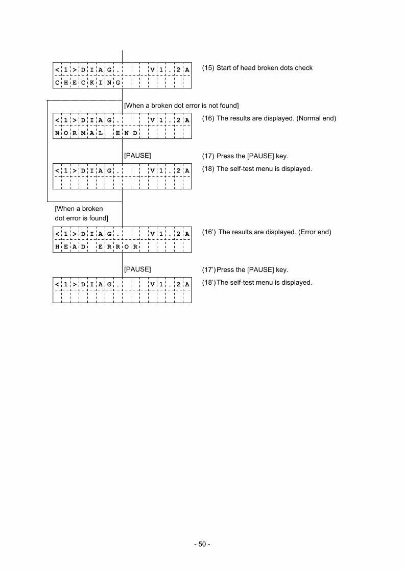
- 50 -
< 1 > D I A G . V 1 . 2 A
C H E C K I N G
(15) Start of head broken dots check
[When a broken dot error is not found]
< 1 > D I A G . V 1 . 2 A
N O R M A L E N D
(16) The results are displayed. (Normal end)
[PAUSE] (17) Press the [PAUSE] key.
< 1 > D I A G . V 1 . 2 A
(18) The self-test menu is displayed.
[When a broken dot error is found]
< 1 > D I A G . V 1 . 2 A
H E A D E R R O R
(16’) The results are displayed. (Error end)
[PAUSE] (17’) Press the [PAUSE] key.
< 1 > D I A G . V 1 . 2 A
(18’) The self-test menu is displayed.
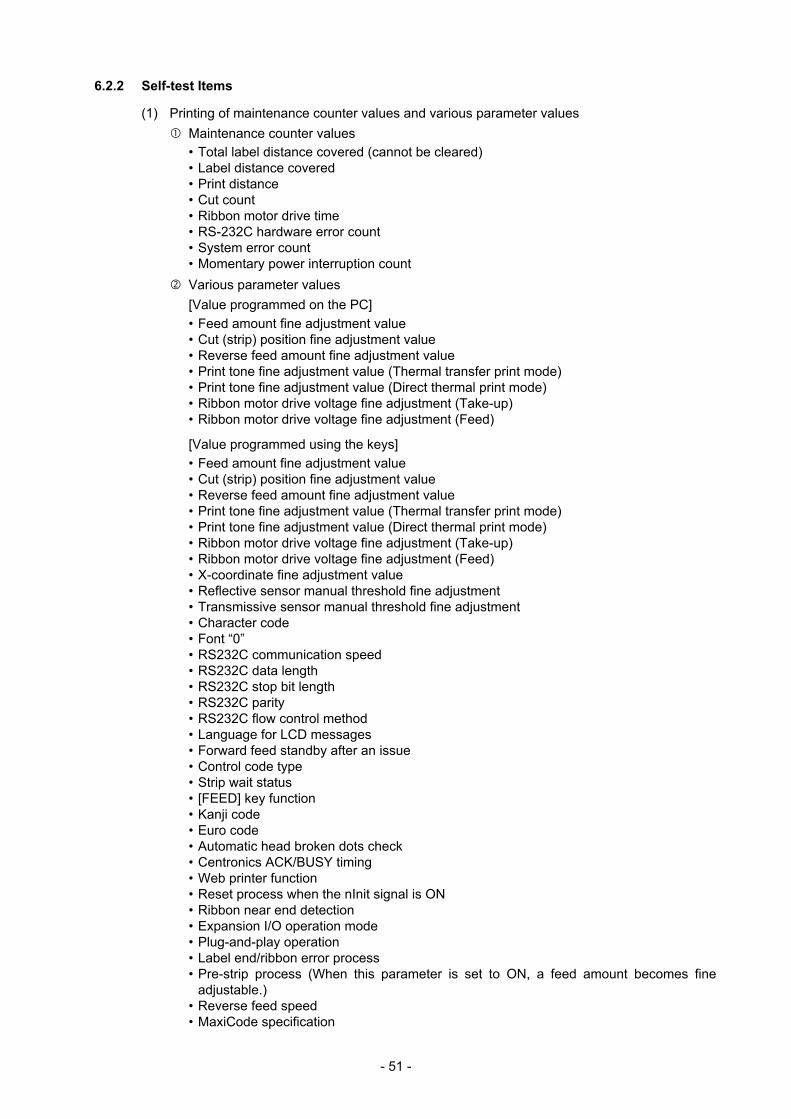
- 51 -
6.2.2 Self-test Items
(1) Printing of maintenance counter values and various parameter values Maintenance counter values • Total label distance covered (cannot be cleared) • Label distance covered • Print distance • Cut count • Ribbon motor drive time • RS-232C hardware error count • System error count • Momentary power interruption count Various parameter values [Value programmed on the PC] • Feed amount fine adjustment value • Cut (strip) position fine adjustment value • Reverse feed amount fine adjustment value • Print tone fine adjustment value (Thermal transfer print mode) • Print tone fine adjustment value (Direct thermal print mode) • Ribbon motor drive voltage fine adjustment (Take-up) • Ribbon motor drive voltage fine adjustment (Feed)
[Value programmed using the keys] • Feed amount fine adjustment value • Cut (strip) position fine adjustment value • Reverse feed amount fine adjustment value • Print tone fine adjustment value (Thermal transfer print mode) • Print tone fine adjustment value (Direct thermal print mode) • Ribbon motor drive voltage fine adjustment (Take-up) • Ribbon motor drive voltage fine adjustment (Feed) • X-coordinate fine adjustment value • Reflective sensor manual threshold fine adjustment • Transmissive sensor manual threshold fine adjustment • Character code • Font “0” • RS232C communication speed • RS232C data length • RS232C stop bit length • RS232C parity • RS232C flow control method • Language for LCD messages • Forward feed standby after an issue • Control code type • Strip wait status • [FEED] key function • Kanji code • Euro code • Automatic head broken dots check • Centronics ACK/BUSY timing • Web printer function • Reset process when the nInit signal is ON • Ribbon near end detection • Expansion I/O operation mode • Plug-and-play operation • Label end/ribbon error process • Pre-strip process (When this parameter is set to ON, a feed amount becomes fine
adjustable.) • Reverse feed speed • MaxiCode specification
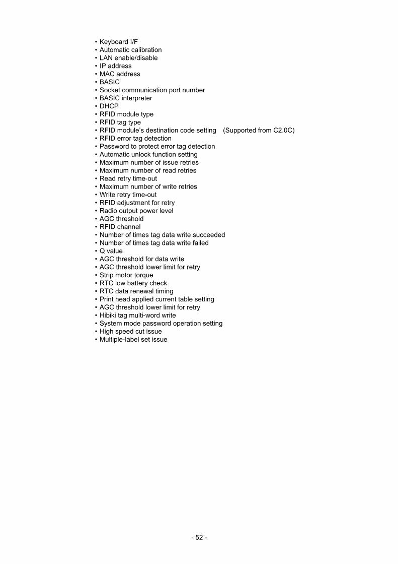
- 52 -
• Keyboard I/F • Automatic calibration • LAN enable/disable • IP address • MAC address • BASIC • Socket communication port number • BASIC interpreter • DHCP • RFID module type • RFID tag type • RFID module’s destination code setting (Supported from C2.0C) • RFID error tag detection • Password to protect error tag detection • Automatic unlock function setting • Maximum number of issue retries • Maximum number of read retries • Read retry time-out • Maximum number of write retries • Write retry time-out • RFID adjustment for retry • Radio output power level • AGC threshold • RFID channel • Number of times tag data write succeeded • Number of times tag data write failed • Q value • AGC threshold for data write • AGC threshold lower limit for retry • Strip motor torque • RTC low battery check • RTC data renewal timing • Print head applied current table setting • AGC threshold lower limit for retry • Hibiki tag multi-word write • System mode password operation setting • High speed cut issue • Multiple-label set issue
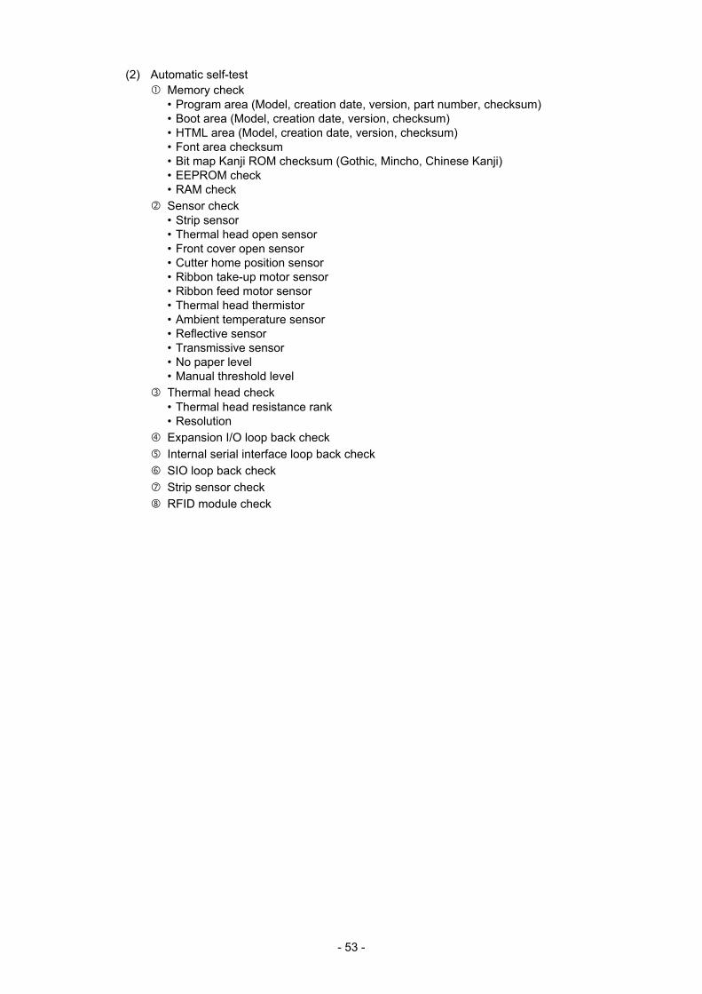
- 53 -
(2) Automatic self-test Memory check • Program area (Model, creation date, version, part number, checksum) • Boot area (Model, creation date, version, checksum) • HTML area (Model, creation date, version, checksum) • Font area checksum • Bit map Kanji ROM checksum (Gothic, Mincho, Chinese Kanji) • EEPROM check • RAM check Sensor check • Strip sensor • Thermal head open sensor • Front cover open sensor • Cutter home position sensor • Ribbon take-up motor sensor • Ribbon feed motor sensor • Thermal head thermistor • Ambient temperature sensor • Reflective sensor • Transmissive sensor • No paper level • Manual threshold level Thermal head check • Thermal head resistance rank • Resolution Expansion I/O loop back check Internal serial interface loop back check SIO loop back check Strip sensor check RFID module check
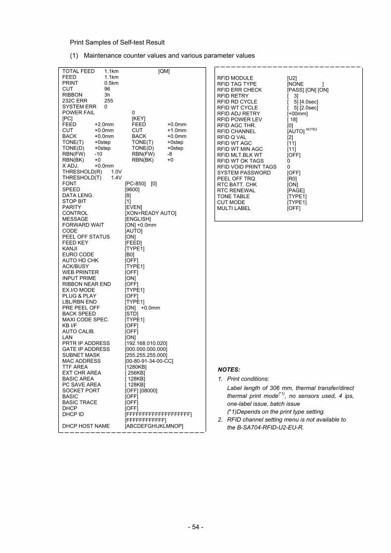
- 54 -
Print Samples of Self-test Result
(1) Maintenance counter values and various parameter values
TOTAL FEED 1.1km [QM] FEED 1.1km PRINT 0.5km CUT 96 RIBBON 3h 232C ERR 255 SYSTEM ERR 0 POWER FAIL 0 [PC] [KEY] FEED +2.0mm FEED +0.0mm CUT +0.0mm CUT +1.0mm BACK +0.0mm BACK +0.0mm TONE(T) +0step TONE(T) +0step TONE(D) +0step TONE(D) +0step RBN(FW) -10 RBN(FW) -8 RBN(BK) +0 RBN(BK) +0 X ADJ. +0.0mm THRESHOLD(R) 1.0V THRESHOLD(T) 1.4V FONT [PC-850] [0] SPEED [9600] DATA LENG. [8] STOP BIT [1] PARITY [EVEN] CONTROL [XON+READY AUTO] MESSAGE [ENGLISH] FORWARD WAIT [ON] +0.0mm CODE [AUTO] PEEL OFF STATUS [ON] FEED KEY [FEED] KANJI [TYPE1] EURO CODE [B0] AUTO HD CHK [OFF] ACK/BUSY [TYPE1] WEB PRINTER [OFF] INPUT PRIME [ON] RIBBON NEAR END [OFF] EX.I/O MODE [TYPE1] PLUG & PLAY [OFF] LBL/RBN END [TYPE1] PRE PEEL OFF [ON] +0.0mm BACK SPEED [STD] MAXI CODE SPEC. [TYPE1] KB I/F [OFF] AUTO CALIB. [OFF] LAN [ON] PRTR IP ADDRESS [192.168.010.020] GATE IP ADDRESS [000.000.000.000] SUBNET MASK [255.255.255.000] MAC ADDRESS [00-80-91-34-00-CC] TTF AREA [1280KB] EXT CHR AREA [ 256KB] BASIC AREA [ 128KB] PC SAVE AREA [ 128KB] SOCKET PORT [OFF] [08000] BASIC [OFF] BASIC TRACE [OFF] DHCP [OFF] DHCP ID [FFFFFFFFFFFFFFFFFFFF] [FFFFFFFFFFFF] DHCP HOST NAME [ABCDEFGHIJKLMNOP]
RFID MODULE [U2] RFID TAG TYPE [NONE ] RFID ERR CHECK [PASS] [ON] [ON] RFID RETRY [ 3] RFID RD CYCLE [ 5] [4.0sec] RFID WT CYCLE [ 5] [2.0sec] RFID ADJ RETRY [+00mm] RFID POWER LEV [ 18] RFID AGC THR. [0] RFID CHANNEL [AUTO] NOTE2 RFID Q VAL [2] RFID WT AGC [11] RFID WT MIN AGC [11] RFID MLT.BLK WT [OFF] RFID WT OK TAGS 0 RFID VOID PRINT TAGS 0 SYSTEM PASSWORD [OFF] PEEL OFF TRQ [R0] RTC BATT. CHK [ON] RTC RENEWAL [PAGE] TONE TABLE [TYPE1] CUT MODE [TYPE1] MULTI LABEL [OFF]
NOTES: 1. Print conditions: Label length of 306 mm, thermal transfer/direct
thermal print mode(*1), no sensors used, 4 ips, one-label issue, batch issue
(*1)Depends on the print type setting. 2. RFID channel setting menu is not available to
the B-SA704-RFID-U2-EU-R.
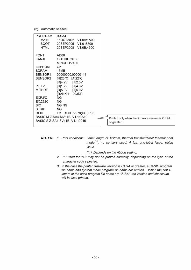
- 55 -
(2) Automatic self-test
NOTES: 1. Print conditions: Label length of 122mm, thermal transfer/direct thermal print mode(*1), no sensors used, 4 ips, one-label issue, batch issue
(*1) Depends on the ribbon setting. 2. “°” used for “°C” may not be printed correctly, depending on the type of the
character code selected. 3. In the case the printer firmware version is C1.9A or greater, a BASIC program
file name and system mode program file name are printed. When the first 4 letters of the each program file name are “Z-SA”, the version and checksum will be also printed.
PROGRAM B-SA4T MAIN 15OCT2005 V1.0A:1A00 BOOT 20SEP2005 V1.0 :8500 HTML 20SEP2008 V1.0B:4300 FONT AD00 KANJI GOTHIC :9F00 MINCHO :7400 EEPROM OK SDRAM 16MB SENSOR1 00000000,00000111 SENSOR2 [H]23°C [A]22°C [R]4.2V [T]2.5V PE LV. [R]1.2V [T]4.3V M THRE. [R]5.0V [T]5.0V
[RANK]1 203DPI EXP.I/O NG EX.232C NG SIO NG NG STRIP NG RFID OK #00U:V978(US )R03 BASIC M Z-SA4-MV11B. V1.1:3A10 BASIC S Z-SA4-SV11B. V1.1:9245
Printed only when the firmware version is C1.9A or greater.
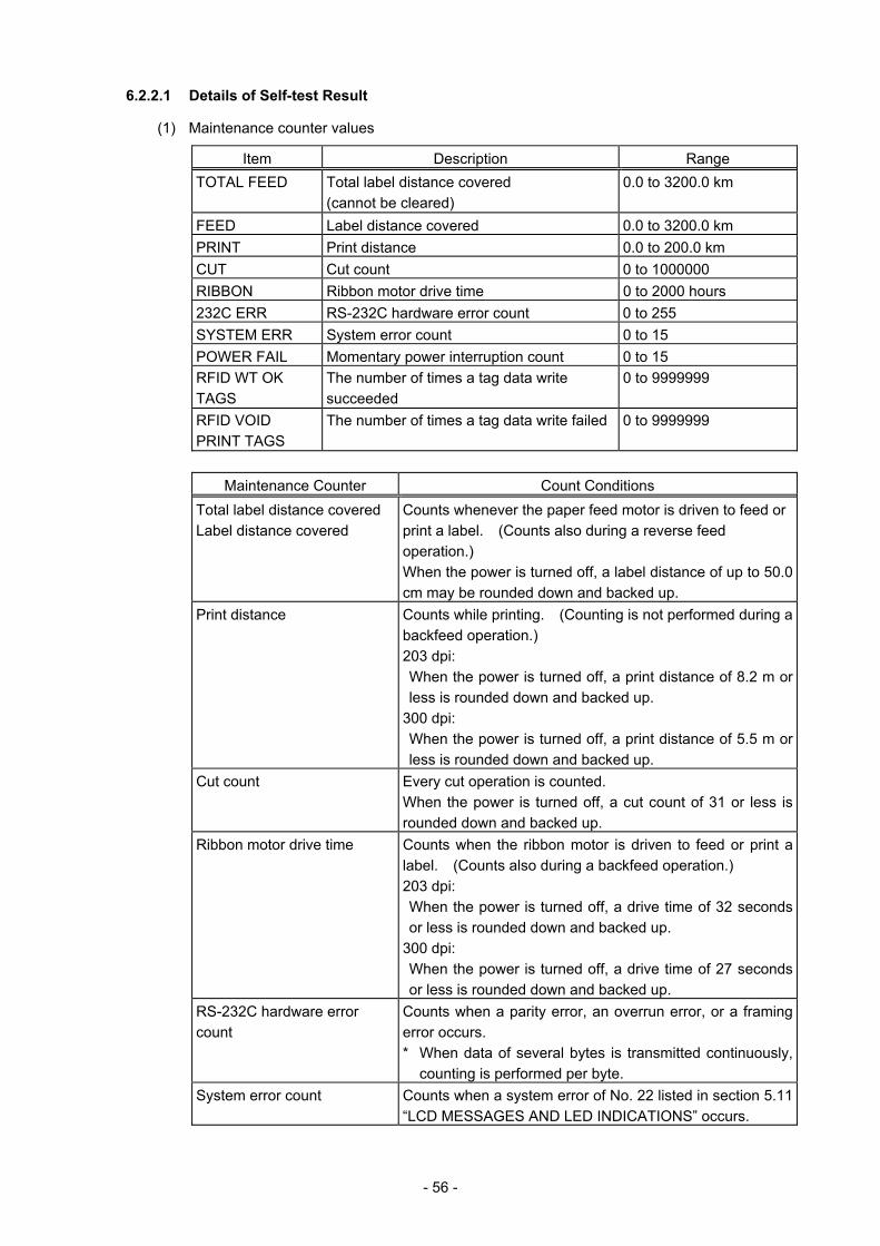
- 56 -
6.2.2.1 Details of Self-test Result
(1) Maintenance counter values
Item Description Range TOTAL FEED Total label distance covered
(cannot be cleared) 0.0 to 3200.0 km
FEED Label distance covered 0.0 to 3200.0 km PRINT Print distance 0.0 to 200.0 km CUT Cut count 0 to 1000000 RIBBON Ribbon motor drive time 0 to 2000 hours 232C ERR RS-232C hardware error count 0 to 255 SYSTEM ERR System error count 0 to 15 POWER FAIL Momentary power interruption count 0 to 15 RFID WT OK TAGS
The number of times a tag data write succeeded
0 to 9999999
RFID VOID PRINT TAGS
The number of times a tag data write failed 0 to 9999999
Maintenance Counter Count Conditions
Total label distance covered Label distance covered
Counts whenever the paper feed motor is driven to feed or print a label. (Counts also during a reverse feed operation.) When the power is turned off, a label distance of up to 50.0 cm may be rounded down and backed up.
Print distance Counts while printing. (Counting is not performed during a backfeed operation.) 203 dpi: When the power is turned off, a print distance of 8.2 m or less is rounded down and backed up.
300 dpi: When the power is turned off, a print distance of 5.5 m or less is rounded down and backed up.
Cut count Every cut operation is counted. When the power is turned off, a cut count of 31 or less is rounded down and backed up.
Ribbon motor drive time Counts when the ribbon motor is driven to feed or print a label. (Counts also during a backfeed operation.) 203 dpi: When the power is turned off, a drive time of 32 seconds or less is rounded down and backed up.
300 dpi: When the power is turned off, a drive time of 27 seconds or less is rounded down and backed up.
RS-232C hardware error count
Counts when a parity error, an overrun error, or a framing error occurs. * When data of several bytes is transmitted continuously,
counting is performed per byte. System error count Counts when a system error of No. 22 listed in section 5.11
“LCD MESSAGES AND LED INDICATIONS” occurs.
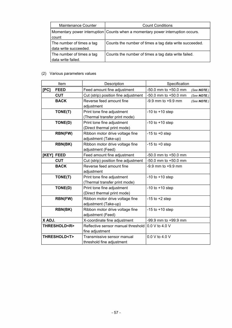
- 57 -
Maintenance Counter Count Conditions Momentary power interruption count
Counts when a momentary power interruption occurs.
The number of times a tag data write succeeded.
Counts the number of times a tag data write succeeded.
The number of times a tag data write failed.
Counts the number of times a tag data write failed.
(2) Various parameters values
Item Description Specification [PC] FEED Feed amount fine adjustment -50.0 mm to +50.0 mm (See NOTE.)
CUT Cut (strip) position fine adjustment -50.0 mm to +50.0 mm (See NOTE.)
BACK Reverse feed amount fine adjustment
-9.9 mm to +9.9 mm (See NOTE.)
TONE(T) Print tone fine adjustment (Thermal transfer print mode)
-10 to +10 step
TONE(D) Print tone fine adjustment (Direct thermal print mode)
-10 to +10 step
RBN(FW) Ribbon motor drive voltage fine adjustment (Take-up)
-15 to +0 step
RBN(BK) Ribbon motor drive voltage fine adjustment (Feed)
-15 to +0 step
[KEY] FEED Feed amount fine adjustment -50.0 mm to +50.0 mm CUT Cut (strip) position fine adjustment -50.0 mm to +50.0 mm BACK Reverse feed amount fine
adjustment -9.9 mm to +9.9 mm
TONE(T) Print tone fine adjustment (Thermal transfer print mode)
-10 to +10 step
TONE(D) Print tone fine adjustment (Direct thermal print mode)
-10 to +10 step
RBN(FW) Ribbon motor drive voltage fine adjustment (Take-up)
-15 to +2 step
RBN(BK) Ribbon motor drive voltage fine adjustment (Feed)
-15 to +10 step
X ADJ. X-coordinate fine adjustment -99.9 mm to +99.9 mm THRESHOLD<R> Reflective sensor manual threshold
fine adjustment 0.0 V to 4.0 V
THRESHOLD<T> Transmissive sensor manual threshold fine adjustment
0.0 V to 4.0 V
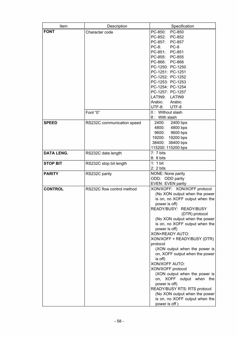
- 58 -
Item Description Specification Character code PC-850: PC-850
PC-852: PC-852 PC-857: PC-857 PC-8: PC-8 PC-851: PC-851 PC-855: PC-855 PC-866: PC-866 PC-1250: PC-1250 PC-1251: PC-1251 PC-1252: PC-1252 PC-1253: PC-1253 PC-1254: PC-1254 PC-1257: PC-1257 LATIN9: LATIN9 Arabic: Arabic UTF-8: UTF-8
FONT
Font “0” 0 : Without slash 0 : With slash
SPEED RS232C communication speed 2400: 2400 bps 4800: 4800 bps 9600: 9600 bps 19200: 19200 bps 38400: 38400 bps 115200: 115200 bps
DATA LENG. RS232C data length 7: 7 bits 8: 8 bits
STOP BIT RS232C stop bit length 1: 1 bit 2: 2 bits
PARITY RS232C parity NONE: None parity ODD: ODD parity EVEN: EVEN parity
CONTROL RS232C flow control method XON/XOFF: XON/XOFF protocol (No XON output when the power is on, no XOFF output when the power is off)
READY/BUSY: READY/BUSY (DTR) protocol
(No XON output when the power is on, no XOFF output when the power is off)
XON+READY AUTO: XON/XOFF + READY/BUSY (DTR) protocol
(XON output when the power is on, XOFF output when the power is off)
XON/XOFF AUTO: XON/XOFF protocol
(XON output when the power is on, XOFF output when the power is off)
READY/BUSY RTS: RTS protocol (No XON output when the power is on, no XOFF output when the power is off )
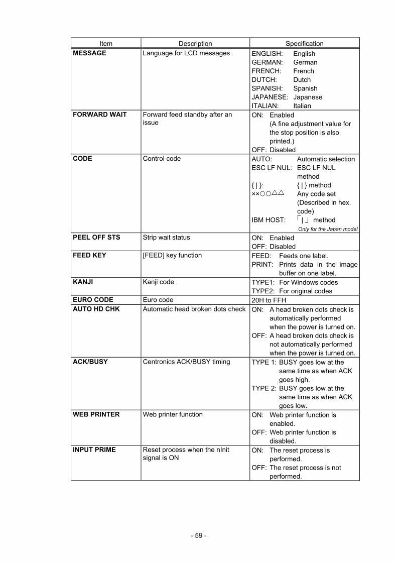
- 59 -
Item Description Specification MESSAGE Language for LCD messages ENGLISH: English
GERMAN: German FRENCH: French DUTCH: Dutch SPANISH: Spanish JAPANESE: Japanese ITALIAN: Italian
FORWARD WAIT Forward feed standby after an issue
ON: Enabled (A fine adjustment value for the stop position is also printed.)
OFF: Disabled CODE Control code AUTO: Automatic selection
ESC LF NUL: ESC LF NUL method
{ | }: { | } method ×× Any code set
(Described in hex. code)
IBM HOST: | method Only for the Japan model
PEEL OFF STS Strip wait status ON: Enabled OFF: Disabled
FEED KEY [FEED] key function FEED: Feeds one label. PRINT: Prints data in the image
buffer on one label. KANJI Kanji code TYPE1: For Windows codes
TYPE2: For original codes EURO CODE Euro code 20H to FFH AUTO HD CHK Automatic head broken dots check ON: A head broken dots check is
automatically performed when the power is turned on.
OFF: A head broken dots check is not automatically performed when the power is turned on.
ACK/BUSY Centronics ACK/BUSY timing TYPE 1: BUSY goes low at the same time as when ACK goes high.
TYPE 2: BUSY goes low at the same time as when ACK goes low.
WEB PRINTER Web printer function ON: Web printer function is enabled.
OFF: Web printer function is disabled.
INPUT PRIME Reset process when the nInit signal is ON
ON: The reset process is performed.
OFF: The reset process is not performed.
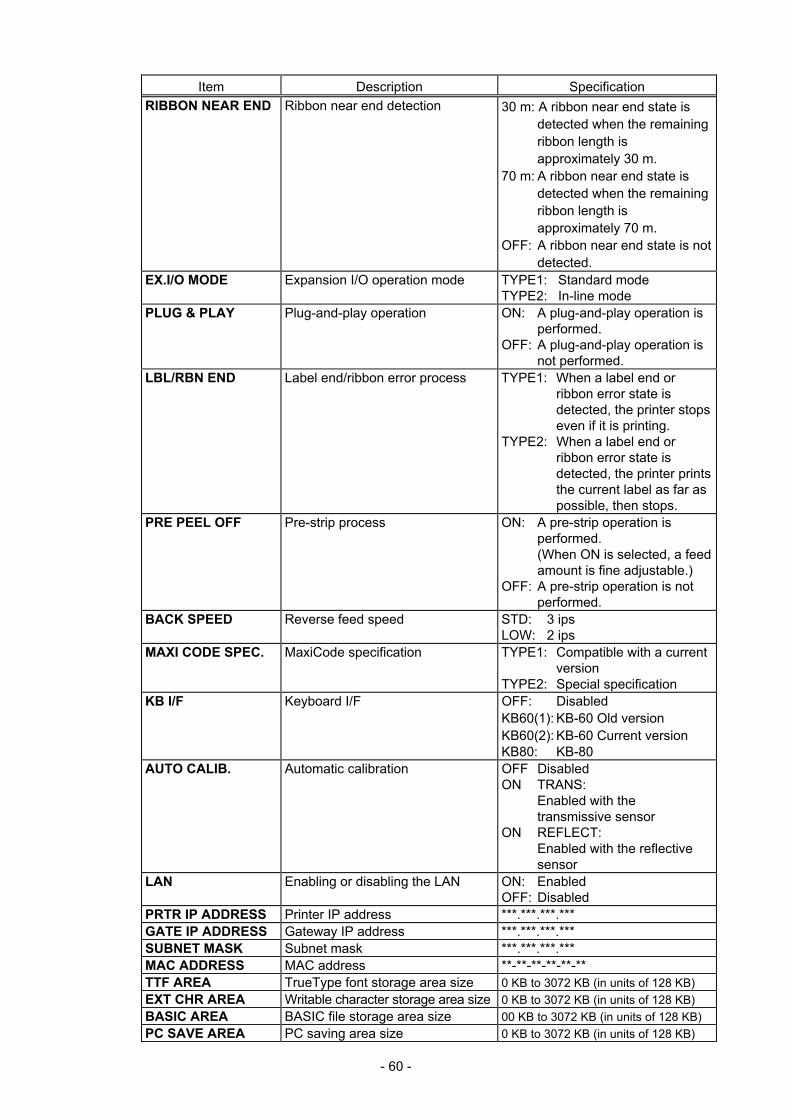
- 60 -
Item Description Specification RIBBON NEAR END Ribbon near end detection 30 m: A ribbon near end state is
detected when the remaining ribbon length is approximately 30 m.
70 m: A ribbon near end state is detected when the remaining ribbon length is approximately 70 m.
OFF: A ribbon near end state is not detected.
EX.I/O MODE Expansion I/O operation mode TYPE1: Standard mode TYPE2: In-line mode
PLUG & PLAY Plug-and-play operation ON: A plug-and-play operation is performed.
OFF: A plug-and-play operation is not performed.
LBL/RBN END Label end/ribbon error process TYPE1: When a label end or ribbon error state is detected, the printer stops even if it is printing.
TYPE2: When a label end or ribbon error state is detected, the printer prints the current label as far as possible, then stops.
PRE PEEL OFF Pre-strip process ON: A pre-strip operation is performed. (When ON is selected, a feed amount is fine adjustable.)
OFF: A pre-strip operation is not performed.
BACK SPEED Reverse feed speed STD: 3 ips LOW: 2 ips
MAXI CODE SPEC. MaxiCode specification TYPE1: Compatible with a current version
TYPE2: Special specification KB I/F Keyboard I/F OFF: Disabled
KB60(1): KB-60 Old version KB60(2): KB-60 Current version KB80: KB-80
AUTO CALIB. Automatic calibration OFF Disabled ON TRANS:
Enabled with the transmissive sensor
ON REFLECT: Enabled with the reflective sensor
LAN Enabling or disabling the LAN ON: Enabled OFF: Disabled
PRTR IP ADDRESS Printer IP address ***.***.***.*** GATE IP ADDRESS Gateway IP address ***.***.***.*** SUBNET MASK Subnet mask ***.***.***.*** MAC ADDRESS MAC address **-**-**-**-**-** TTF AREA TrueType font storage area size 0 KB to 3072 KB (in units of 128 KB) EXT CHR AREA Writable character storage area size 0 KB to 3072 KB (in units of 128 KB) BASIC AREA BASIC file storage area size 00 KB to 3072 KB (in units of 128 KB) PC SAVE AREA PC saving area size 0 KB to 3072 KB (in units of 128 KB)
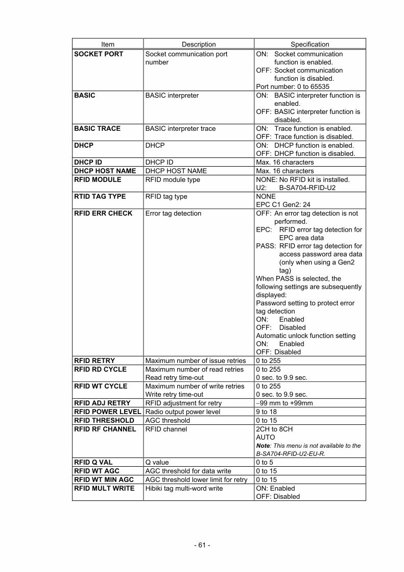
- 61 -
Item Description Specification SOCKET PORT Socket communication port
number ON: Socket communication
function is enabled. OFF: Socket communication
function is disabled. Port number: 0 to 65535
BASIC BASIC interpreter ON: BASIC interpreter function is enabled.
OFF: BASIC interpreter function is disabled.
BASIC TRACE BASIC interpreter trace ON: Trace function is enabled. OFF: Trace function is disabled.
DHCP DHCP ON: DHCP function is enabled. OFF: DHCP function is disabled.
DHCP ID DHCP ID Max. 16 characters DHCP HOST NAME DHCP HOST NAME Max. 16 characters RFID MODULE RFID module type NONE: No RFID kit is installed.
U2: B-SA704-RFID-U2 RTID TAG TYPE RFID tag type NONE
EPC C1 Gen2: 24 RFID ERR CHECK Error tag detection OFF: An error tag detection is not
performed. EPC: RFID error tag detection for
EPC area data PASS: RFID error tag detection for
access password area data (only when using a Gen2 tag)
When PASS is selected, the following settings are subsequently displayed: Password setting to protect error tag detection ON: Enabled OFF: Disabled Automatic unlock function setting ON: Enabled OFF: Disabled
RFID RETRY Maximum number of issue retries 0 to 255 RFID RD CYCLE Maximum number of read retries
Read retry time-out 0 to 255 0 sec. to 9.9 sec.
RFID WT CYCLE Maximum number of write retries Write retry time-out
0 to 255 0 sec. to 9.9 sec.
RFID ADJ RETRY RFID adjustment for retry −99 mm to +99mm RFID POWER LEVEL Radio output power level 9 to 18 RFID THRESHOLD AGC threshold 0 to 15 RFID RF CHANNEL RFID channel 2CH to 8CH
AUTO Note: This menu is not available to the B-SA704-RFID-U2-EU-R.
RFID Q VAL Q value 0 to 5 RFID WT AGC AGC threshold for data write 0 to 15 RFID WT MIN AGC AGC threshold lower limit for retry 0 to 15 RFID MULT WRITE Hibiki tag multi-word write ON: Enabled
OFF: Disabled
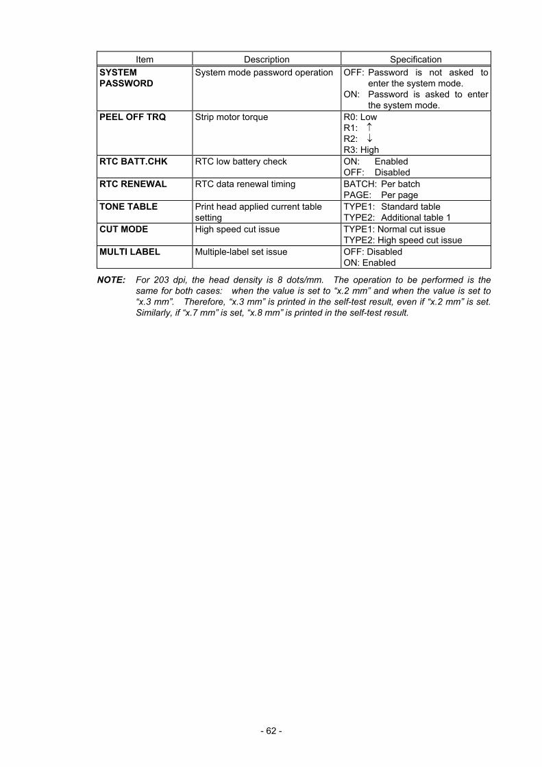
- 62 -
Item Description Specification SYSTEM PASSWORD
System mode password operation OFF: Password is not asked to enter the system mode.
ON: Password is asked to enter the system mode.
PEEL OFF TRQ Strip motor torque R0: Low R1: ↑ R2: ↓ R3: High
RTC BATT.CHK RTC low battery check ON: Enabled OFF: Disabled
RTC RENEWAL RTC data renewal timing BATCH: Per batch PAGE: Per page
TONE TABLE Print head applied current table setting
TYPE1: Standard table TYPE2: Additional table 1
CUT MODE High speed cut issue TYPE1: Normal cut issue TYPE2: High speed cut issue
MULTI LABEL Multiple-label set issue OFF: Disabled ON: Enabled
NOTE: For 203 dpi, the head density is 8 dots/mm. The operation to be performed is the same for both cases: when the value is set to “x.2 mm” and when the value is set to “x.3 mm”. Therefore, “x.3 mm” is printed in the self-test result, even if “x.2 mm” is set. Similarly, if “x.7 mm” is set, “x.8 mm” is printed in the self-test result.
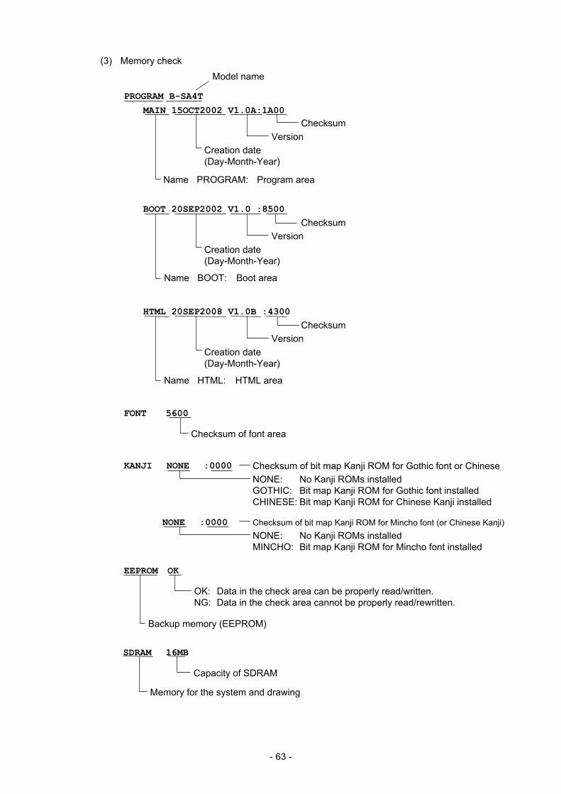
- 63 -
(3) Memory check
EEPROM OK
OK: Data in the check area can be properly read/written. NG: Data in the check area cannot be properly read/rewritten.
Backup memory (EEPROM)
PROGRAM B-SA4T
MAIN 15OCT2002 V1.0A:1A00
Model name
Creation date (Day-Month-Year)
Version
Name PROGRAM: Program area
Checksum
BOOT 20SEP2002 V1.0 :8500
Creation date (Day-Month-Year)
Version
Name BOOT: Boot area
Checksum
KANJI NONE :0000
NONE :0000
Checksum of bit map Kanji ROM for Gothic font or ChineseNONE: No Kanji ROMs installed GOTHIC: Bit map Kanji ROM for Gothic font installed CHINESE: Bit map Kanji ROM for Chinese Kanji installed
Checksum of bit map Kanji ROM for Mincho font (or Chinese Kanji) NONE: No Kanji ROMs installed MINCHO: Bit map Kanji ROM for Mincho font installed
SDRAM 16MB
Capacity of SDRAM
Memory for the system and drawing
FONT 5600
Checksum of font area
HTML 20SEP2008 V1.0B :4300
Creation date (Day-Month-Year)
Version
Name HTML: HTML area
Checksum
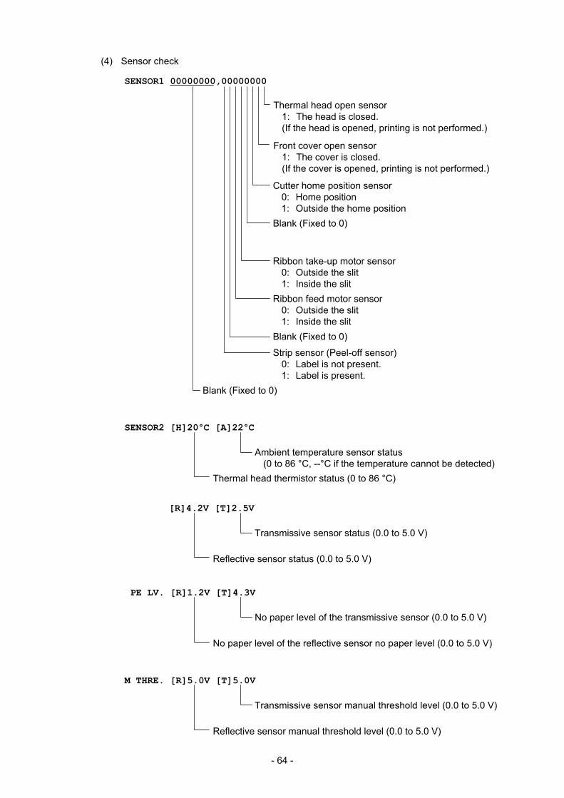
- 64 -
(4) Sensor check
SENSOR1 00000000,00000000
Thermal head open sensor 1: The head is closed. (If the head is opened, printing is not performed.)
Blank (Fixed to 0)
Blank (Fixed to 0)
Cutter home position sensor 0: Home position 1: Outside the home position Blank (Fixed to 0)
Ribbon take-up motor sensor 0: Outside the slit 1: Inside the slit Ribbon feed motor sensor 0: Outside the slit 1: Inside the slit
Strip sensor (Peel-off sensor) 0: Label is not present. 1: Label is present.
Front cover open sensor 1: The cover is closed. (If the cover is opened, printing is not performed.)
SENSOR2 [H]20°C [A]22°C
Ambient temperature sensor status (0 to 86 °C, --°C if the temperature cannot be detected)
Thermal head thermistor status (0 to 86 °C)
PE LV. [R]1.2V [T]4.3V
No paper level of the transmissive sensor (0.0 to 5.0 V)
No paper level of the reflective sensor no paper level (0.0 to 5.0 V)
[R]4.2V [T]2.5V
Transmissive sensor status (0.0 to 5.0 V)
Reflective sensor status (0.0 to 5.0 V)
M THRE. [R]5.0V [T]5.0V
Transmissive sensor manual threshold level (0.0 to 5.0 V)
Reflective sensor manual threshold level (0.0 to 5.0 V)
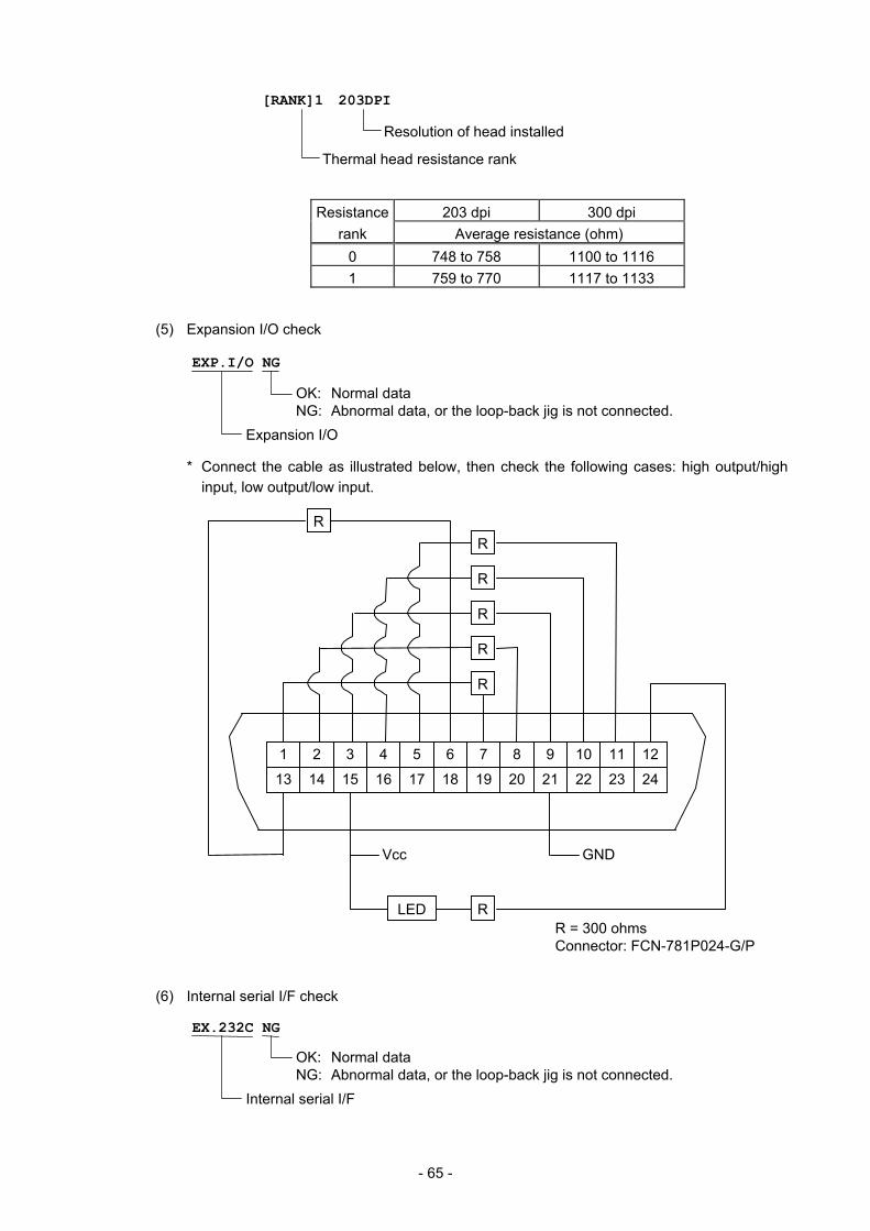
- 65 -
Resistance 203 dpi 300 dpi rank Average resistance (ohm)
0 748 to 758 1100 to 1116 1 759 to 770 1117 to 1133
(5) Expansion I/O check
* Connect the cable as illustrated below, then check the following cases: high output/high
input, low output/low input.
(6) Internal serial I/F check
OK: Normal data NG: Abnormal data, or the loop-back jig is not connected.
Expansion I/O
EXP.I/O NG
R R
R
R
R
R
R
Vcc
LEDR = 300 ohms Connector: FCN-781P024-G/P
GND
12 11 1098764 53 1 2
24 23 222120191816 1715 13 14
EX.232C NG
OK: Normal data NG: Abnormal data, or the loop-back jig is not connected.
Internal serial I/F
[RANK]1 203DPI
Thermal head resistance rank
Resolution of head installed
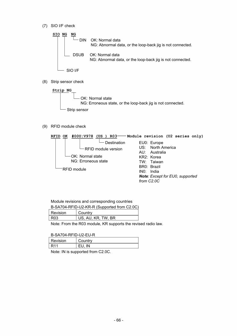
- 66 -
(7) SIO I/F check
(8) Strip sensor check
(9) RFID module check
Module revisions and corresponding countries B-SA704-RFID-U2-KR-R (Supported from C2.0C) Revision Country R03 US, AU, KR, TW, BR Note: From the R03 module, KR supports the revised radio law. B-SA704-RFID-U2-EU-R Revision Country R11 EU, IN Note: IN is supported from C2.0C.
SIO NG NG
DIN OK: Normal data NG: Abnormal data, or the loop-back jig is not connected.
DSUB OK: Normal data NG: Abnormal data, or the loop-back jig is not connected.
SIO I/F
Strip NG
OK: Normal state NG: Erroneous state, or the loop-back jig is not connected.
Strip sensor
RFID OK #00U:V978 (US ) R03 Module revision (U2 series only)
OK: Normal state NG: Erroneous state
RFID module version
RFID module
Destination EU0: Europe US: North America AU: Australia KR2: Korea TW: Taiwan BR0: Brazil IN0: India Note: Except for EU0, supported
from C2.0C
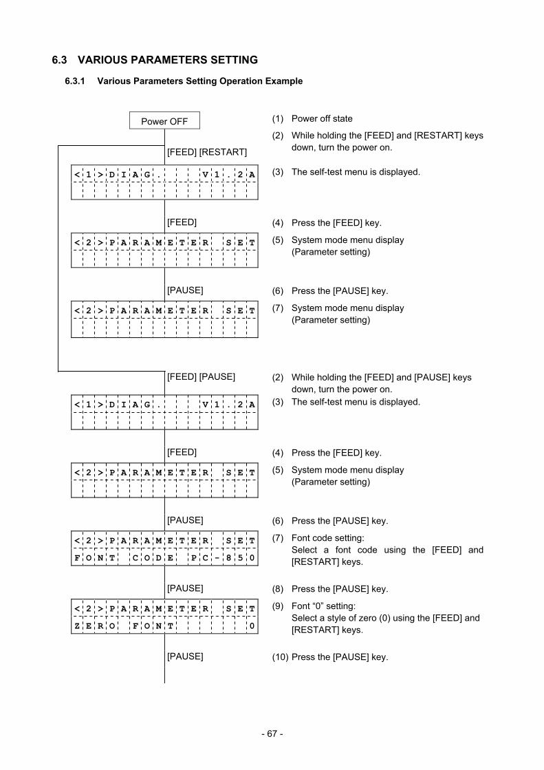
- 67 -
6.3 VARIOUS PARAMETERS SETTING
6.3.1 Various Parameters Setting Operation Example
Power OFF (1) Power off state
[FEED] [RESTART]
(2) While holding the [FEED] and [RESTART] keys down, turn the power on.
< 1 > D I A G . V 1 . 2 A
(3) The self-test menu is displayed.
[FEED] (4) Press the [FEED] key.
< 2 > P A R A M E T E R S E T
(5) System mode menu display (Parameter setting)
[PAUSE] (6) Press the [PAUSE] key.
< 2 > P A R A M E T E R S E T
(7) System mode menu display (Parameter setting)
[FEED] [PAUSE] (2) While holding the [FEED] and [PAUSE] keys down, turn the power on.
< 1 > D I A G . V 1 . 2 A
(3) The self-test menu is displayed.
[FEED] (4) Press the [FEED] key.
< 2 > P A R A M E T E R S E T
(5) System mode menu display (Parameter setting)
[PAUSE] (6) Press the [PAUSE] key.
< 2 > P A R A M E T E R S E T F O N T C O D E P C - 8 5 0
(7) Font code setting: Select a font code using the [FEED] and
[RESTART] keys.
[PAUSE] (8) Press the [PAUSE] key.
< 2 > P A R A M E T E R S E T Z E R O F O N T 0
(9) Font “0” setting: Select a style of zero (0) using the [FEED] and
[RESTART] keys.
[PAUSE] (10) Press the [PAUSE] key.
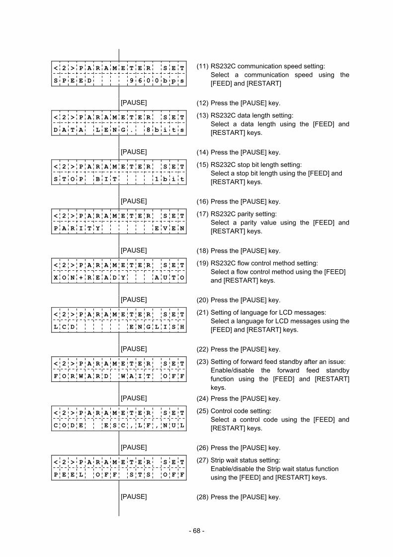
- 68 -
< 2 > P A R A M E T E R S E T S P E E D 9 6 0 0 b p s
(11) RS232C communication speed setting: Select a communication speed using the
[FEED] and [RESTART]
[PAUSE] (12) Press the [PAUSE] key.
< 2 > P A R A M E T E R S E T D A T A L E N G . 8 b i t s
(13) RS232C data length setting: Select a data length using the [FEED] and
[RESTART] keys.
[PAUSE] (14) Press the [PAUSE] key.
< 2 > P A R A M E T E R S E T S T O P B I T 1 b i t
(15) RS232C stop bit length setting: Select a stop bit length using the [FEED] and
[RESTART] keys.
[PAUSE] (16) Press the [PAUSE] key.
< 2 > P A R A M E T E R S E T P A R I T Y E V E N
(17) RS232C parity setting: Select a parity value using the [FEED] and
[RESTART] keys.
[PAUSE] (18) Press the [PAUSE] key.
< 2 > P A R A M E T E R S E T X O N + R E A D Y A U T O
(19) RS232C flow control method setting: Select a flow control method using the [FEED]
and [RESTART] keys.
[PAUSE] (20) Press the [PAUSE] key.
< 2 > P A R A M E T E R S E T L C D E N G L I S H
(21) Setting of language for LCD messages: Select a language for LCD messages using the
[FEED] and [RESTART] keys.
[PAUSE] (22) Press the [PAUSE] key.
< 2 > P A R A M E T E R S E T F O R W A R D W A I T O F F
(23) Setting of forward feed standby after an issue: Enable/disable the forward feed standby
function using the [FEED] and [RESTART] keys.
[PAUSE] (24) Press the [PAUSE] key.
< 2 > P A R A M E T E R S E T C O D E E S C , L F , N U L
(25) Control code setting: Select a control code using the [FEED] and
[RESTART] keys.
[PAUSE] (26) Press the [PAUSE] key.
< 2 > P A R A M E T E R S E T P E E L O F F S T S O F F
(27) Strip wait status setting: Enable/disable the Strip wait status function
using the [FEED] and [RESTART] keys.
[PAUSE] (28) Press the [PAUSE] key.
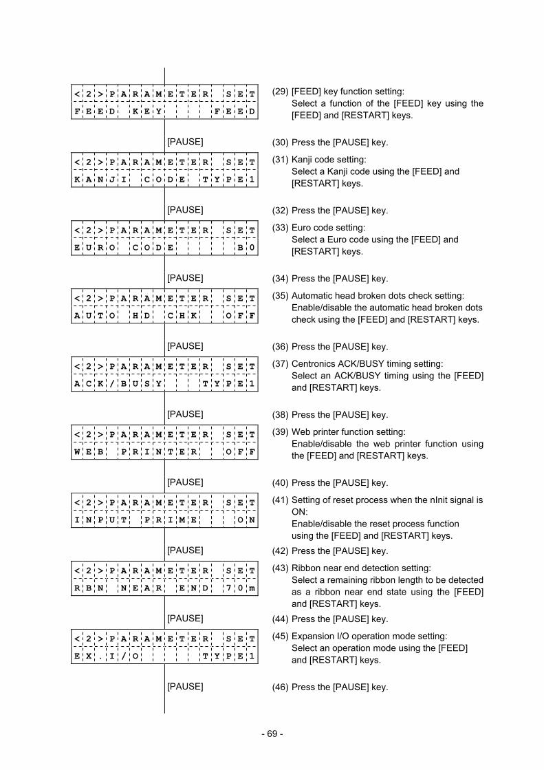
- 69 -
< 2 > P A R A M E T E R S E T F E E D K E Y F E E D
(29) [FEED] key function setting: Select a function of the [FEED] key using the
[FEED] and [RESTART] keys.
[PAUSE] (30) Press the [PAUSE] key.
< 2 > P A R A M E T E R S E T K A N J I C O D E T Y P E 1
(31) Kanji code setting: Select a Kanji code using the [FEED] and [RESTART] keys.
[PAUSE] (32) Press the [PAUSE] key.
< 2 > P A R A M E T E R S E T E U R O C O D E B 0
(33) Euro code setting: Select a Euro code using the [FEED] and
[RESTART] keys.
[PAUSE] (34) Press the [PAUSE] key.
< 2 > P A R A M E T E R S E T A U T O H D C H K O F F
(35) Automatic head broken dots check setting: Enable/disable the automatic head broken dots
check using the [FEED] and [RESTART] keys.
[PAUSE] (36) Press the [PAUSE] key.
< 2 > P A R A M E T E R S E T A C K / B U S Y T Y P E 1
(37) Centronics ACK/BUSY timing setting: Select an ACK/BUSY timing using the [FEED]
and [RESTART] keys.
[PAUSE] (38) Press the [PAUSE] key.
< 2 > P A R A M E T E R S E T W E B P R I N T E R O F F
(39) Web printer function setting: Enable/disable the web printer function using
the [FEED] and [RESTART] keys.
[PAUSE] (40) Press the [PAUSE] key.
< 2 > P A R A M E T E R S E T I N P U T P R I M E O N
(41) Setting of reset process when the nInit signal is ON:
Enable/disable the reset process function using the [FEED] and [RESTART] keys.
[PAUSE] (42) Press the [PAUSE] key.
< 2 > P A R A M E T E R S E T R B N N E A R E N D 7 0 m
(43) Ribbon near end detection setting: Select a remaining ribbon length to be detected
as a ribbon near end state using the [FEED] and [RESTART] keys.
[PAUSE] (44) Press the [PAUSE] key.
< 2 > P A R A M E T E R S E T E X . I / O T Y P E 1
(45) Expansion I/O operation mode setting: Select an operation mode using the [FEED]
and [RESTART] keys.
[PAUSE] (46) Press the [PAUSE] key.
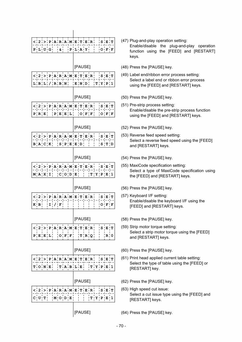
- 70 -
< 2 > P A R A M E T E R S E T P L U G & P L A Y O F F
(47) Plug-and-play operation setting: Enable/disable the plug-and-play operation
function using the [FEED] and [RESTART] keys.
[PAUSE] (48) Press the [PAUSE] key.
< 2 > P A R A M E T E R S E T L B L / R B N E N D T Y P 1
(49) Label end/ribbon error process setting: Select a label end or ribbon error process
using the [FEED] and [RESTART] keys.
[PAUSE] (50) Press the [PAUSE] key.
< 2 > P A R A M E T E R S E T P R E P E E L O F F O F F
(51) Pre-strip process setting: Enable/disable the pre-strip process function
using the [FEED] and [RESTART] keys.
[PAUSE] (52) Press the [PAUSE] key.
< 2 > P A R A M E T E R S E T B A C K S P E E D S T D
(53) Reverse feed speed setting: Select a reverse feed speed using the [FEED]
and [RESTART] keys.
[PAUSE] (54) Press the [PAUSE] key.
< 2 > P A R A M E T E R S E T M A X I C O D E T Y P E 1
(55) MaxiCode specification setting: Select a type of MaxiCode specification using
the [FEED] and [RESTART] keys.
[PAUSE] (56) Press the [PAUSE] key.
< 2 > P A R A M E T E R S E T K B I / F O F F
(57) Keyboard I/F setting: Enable/disable the keyboard I/F using the [FEED] and [RESTART] keys.
[PAUSE] (58) Press the [PAUSE] key.
< 2 > P A R A M E T E R S E T
P E E L O F F T R Q R 0
(59) Strip motor torque setting: Select a strip motor torque using the [FEED] and [RESTART] keys.
[PAUSE] (60) Press the [PAUSE] key.
< 2 > P A R A M E T E R S E T
T O N E T A B L E T Y P E 1
(61) Print head applied current table setting: Select the type of table using the [FEED] or [RESTART] key.
[PAUSE] (62) Press the [PAUSE] key.
< 2 > P A R A M E T E R S E T C U T M O D E T Y P E 1
(63) High speed cut issue: Select a cut issue type using the [FEED] and [RESTART] keys.
[PAUSE] (64) Press the [PAUSE] key.
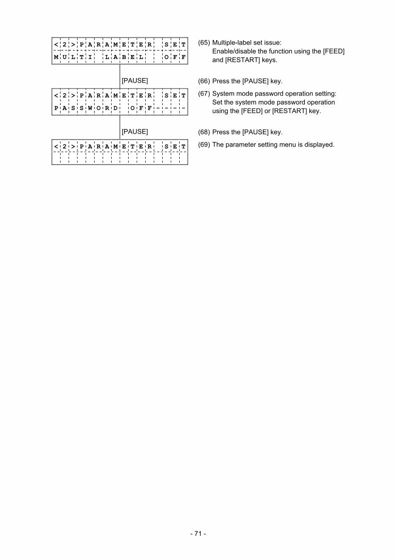
- 71 -
< 2 > P A R A M E T E R S E T
M U L T I L A B E L O F F
(65) Multiple-label set issue: Enable/disable the function using the [FEED] and [RESTART] keys.
[PAUSE] (66) Press the [PAUSE] key.
< 2 > P A R A M E T E R S E T
P A S S W O R D O F F - - - -
(67) System mode password operation setting: Set the system mode password operation using the [FEED] or [RESTART] key.
[PAUSE] (68) Press the [PAUSE] key.
< 2 > P A R A M E T E R S E T (69) The parameter setting menu is displayed.

- 72 -
FEED
RESTART
6.3.2 Details of Various Parameter Setting
(1) Character code (FONT CODE)
• PC-8 • PC-857 • PC-852 • PC-850 • Arabic • LATIN9 • PC-1257 • PC-1254 • PC-1253 • PC-1252 • PC-1251 • PC-1250 • PC-855 • PC-851 • PC-866 • UTF-8
(2) Font “0” (ZERO FONT)
• 0 (Without slash) • 0 (With slash)
(3) RS-232C communication speed (SPEED)
• 115200 bps • 38400 bps • 19200 bps • 9600 bps • 4800 bps • 2400 bps
FEED
RESTART
FEED
RESTART
NOTE: The following fonts do not support a zero with a slash. Therefore, even if a zero with a slash is selected, a zero without a slash is used.
[Bit map fonts] OCR-A, OCR-B, GOTHIC725 Black, Kanji,
Chinese Kanji [Outline fonts] Price fonts 1, 2, and 3, DUTCH801 Bold,
BRUSH738 Regular, GOTHIC725 Black, TrueType font
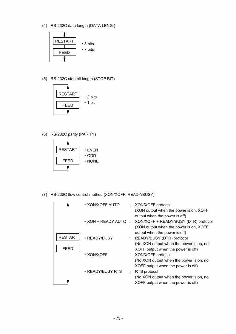
- 73 -
(4) RS-232C data length (DATA LENG.)
• 8 bits • 7 bits
(5) RS-232C stop bit length (STOP BIT)
• 2 bits • 1 bit
(6) RS-232C parity (PARITY)
• EVEN • ODD • NONE
(7) RS-232C flow control method (XON/XOFF, READY/BUSY)
• XON/XOFF AUTO : XON/XOFF protocol (XON output when the power is on, XOFF
output when the power is off) • XON + READY AUTO : XON/XOFF + READY/BUSY (DTR) protocol (XON output when the power is on, XOFF
output when the power is off) • READY/BUSY : READY/BUSY (DTR) protocol (No XON output when the power is on, no
XOFF output when the power is off) • XON/XOFF : XON/XOFF protocol (No XON output when the power is on, no
XOFF output when the power is off) • READY/BUSY RTS : RTS protocol (No XON output when the power is on, no
XOFF output when the power is off)
FEED
RESTART
FEED
RESTART
FEED
RESTART
FEED
RESTART
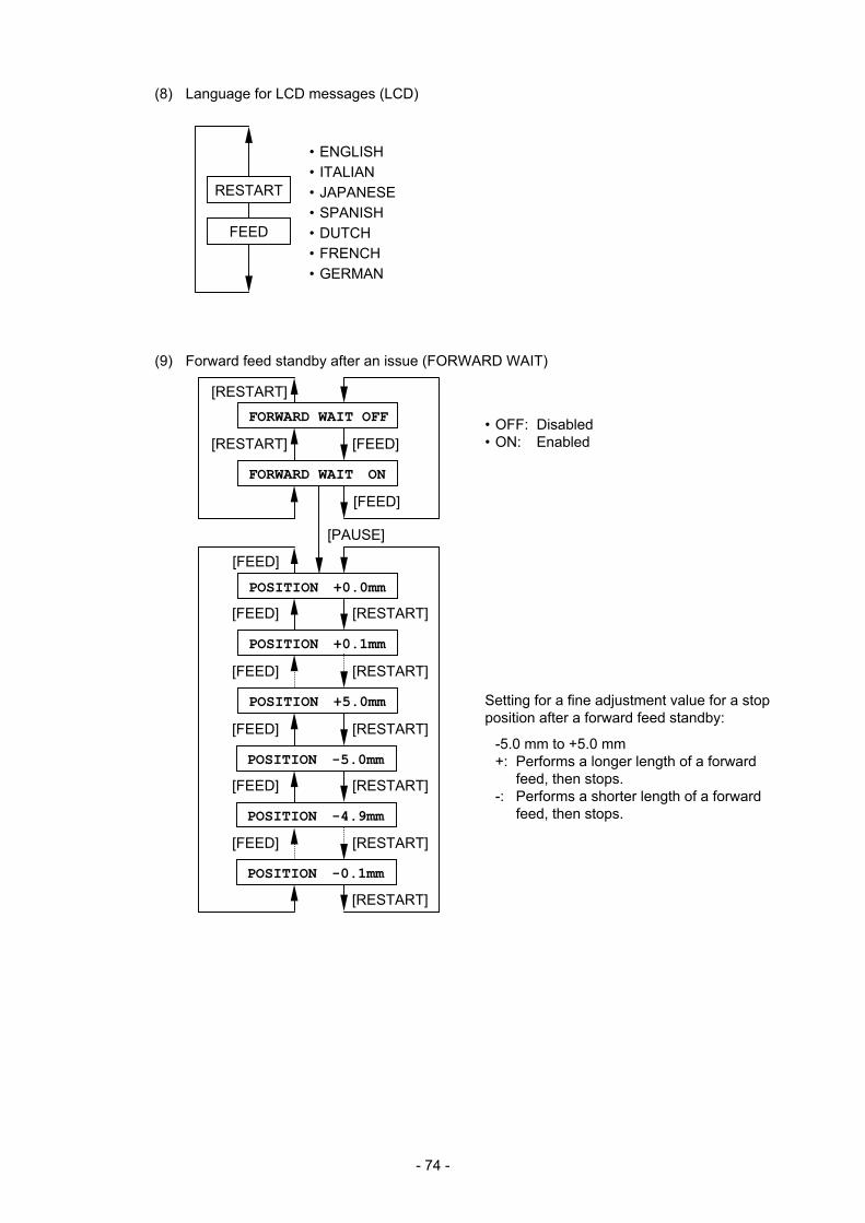
- 74 -
(8) Language for LCD messages (LCD)
• ENGLISH • ITALIAN • JAPANESE • SPANISH • DUTCH • FRENCH • GERMAN
(9) Forward feed standby after an issue (FORWARD WAIT)
FEED
RESTART
[FEED] [RESTART]
FORWARD WAIT OFF
FORWARD WAIT ON
POSITION +0.0mm
POSITION +0.1mm
POSITION +5.0mm
POSITION -5.0mm
[PAUSE]
[FEED] [RESTART]
[FEED] [RESTART]
[FEED] [RESTART]
[FEED]
[RESTART]
POSITION -4.9mm
[FEED] [RESTART]
POSITION -0.1mm
[FEED] [RESTART]
• OFF: Disabled • ON: Enabled
Setting for a fine adjustment value for a stop position after a forward feed standby:
-5.0 mm to +5.0 mm +: Performs a longer length of a forward
feed, then stops. -: Performs a shorter length of a forward
feed, then stops.
[FEED]
[RESTART]
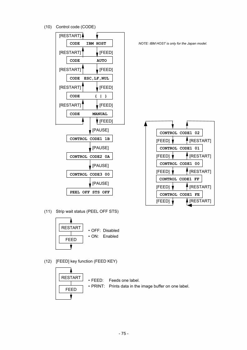
- 75 -
(10) Control code (CODE)
(11) Strip wait status (PEEL OFF STS)
• OFF: Disabled • ON: Enabled
(12) [FEED] key function (FEED KEY)
• FEED: Feeds one label. • PRINT: Prints data in the image buffer on one label.
FEED
RESTART
[FEED] [RESTART]
CODE AUTO
CODE ESC,LF,NUL
CODE { | }
CONTROL CODE1 1B
CODE MANUAL
CONTROL CODE2 0A
[PAUSE]
PEEL OFF STS OFF
CONTROL CODE3 00
[FEED] [RESTART]
[FEED] [RESTART]
[PAUSE]
[PAUSE]
[PAUSE]
[FEED]
[FEED] [RESTART]
CONTROL CODE1 02
CONTROL CODE1 01
CONTROL CODE1 FE
CONTROL CODE1 00
CONTROL CODE1 FF
[FEED] [RESTART]
[FEED] [RESTART]
[FEED] [RESTART]
[RESTART]
[FEED]
[RESTART]
FEED
RESTART
[FEED] [RESTART]
CODE IBM HOST NOTE: IBM HOST is only for the Japan model.
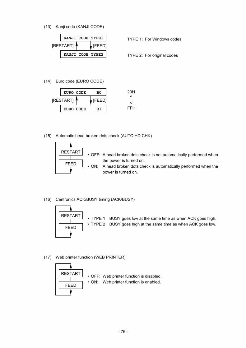
- 76 -
(13) Kanji code (KANJI CODE)
(14) Euro code (EURO CODE)
(15) Automatic head broken dots check (AUTO HD CHK)
• OFF: A head broken dots check is not automatically performed when the power is turned on.
• ON: A head broken dots check is automatically performed when the power is turned on.
(16) Centronics ACK/BUSY timing (ACK/BUSY)
• TYPE 1 BUSY goes low at the same time as when ACK goes high. • TYPE 2 BUSY goes high at the same time as when ACK goes low.
(17) Web printer function (WEB PRINTER)
• OFF: Web printer function is disabled. • ON: Web printer function is enabled.
TYPE 1: For Windows codes
TYPE 2: For original codes
FEED
RESTART
FEED
RESTART
FEED
RESTART
20H
FFH
KANJI CODE TYPE1
KANJI CODE TYPE2
[FEED][RESTART]
EURO CODE B0
EURO CODE B1
[FEED][RESTART]
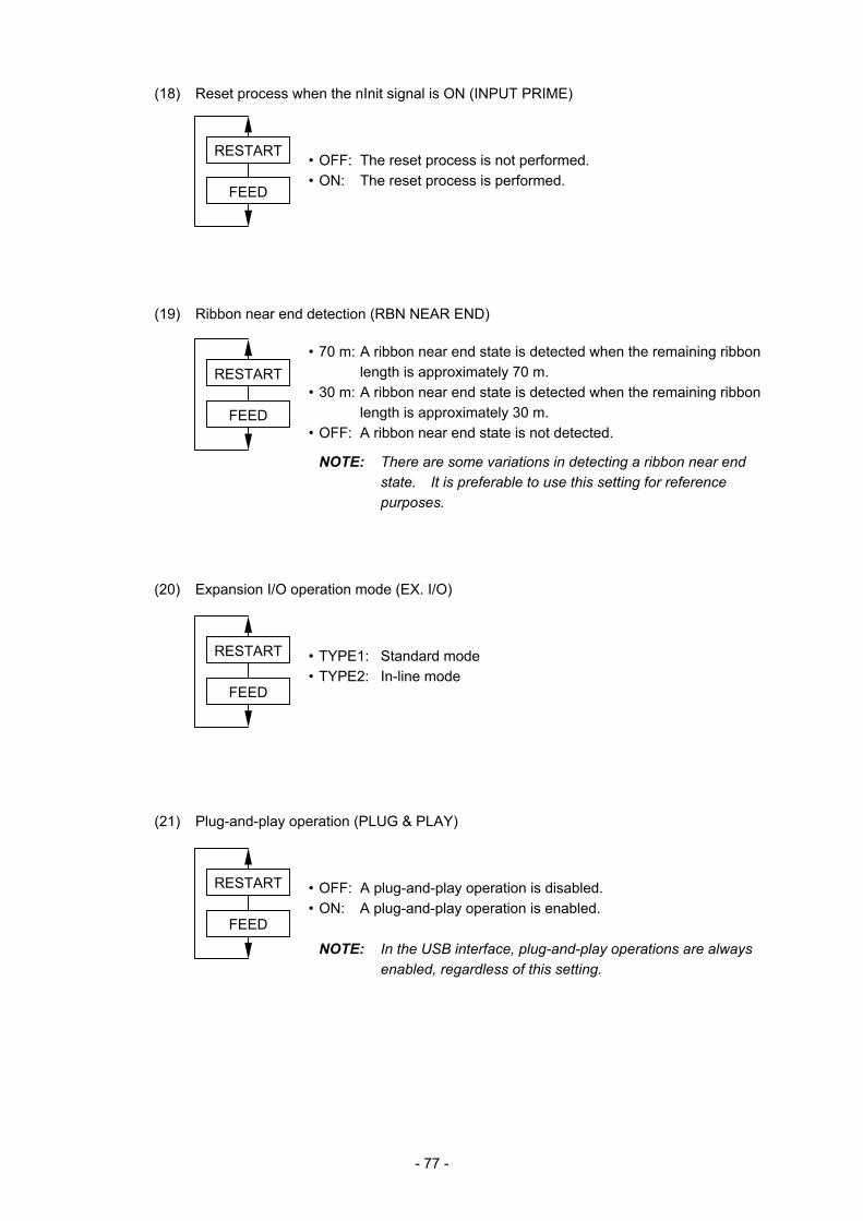
- 77 -
(18) Reset process when the nInit signal is ON (INPUT PRIME)
• OFF: The reset process is not performed. • ON: The reset process is performed.
(19) Ribbon near end detection (RBN NEAR END)
• 70 m: A ribbon near end state is detected when the remaining ribbon length is approximately 70 m.
• 30 m: A ribbon near end state is detected when the remaining ribbon length is approximately 30 m.
• OFF: A ribbon near end state is not detected.
NOTE: There are some variations in detecting a ribbon near end state. It is preferable to use this setting for reference purposes.
(20) Expansion I/O operation mode (EX. I/O)
• TYPE1: Standard mode • TYPE2: In-line mode
(21) Plug-and-play operation (PLUG & PLAY)
• OFF: A plug-and-play operation is disabled. • ON: A plug-and-play operation is enabled. NOTE: In the USB interface, plug-and-play operations are always
enabled, regardless of this setting.
FEED
RESTART
FEED
RESTART
FEED
RESTART
FEED
RESTART
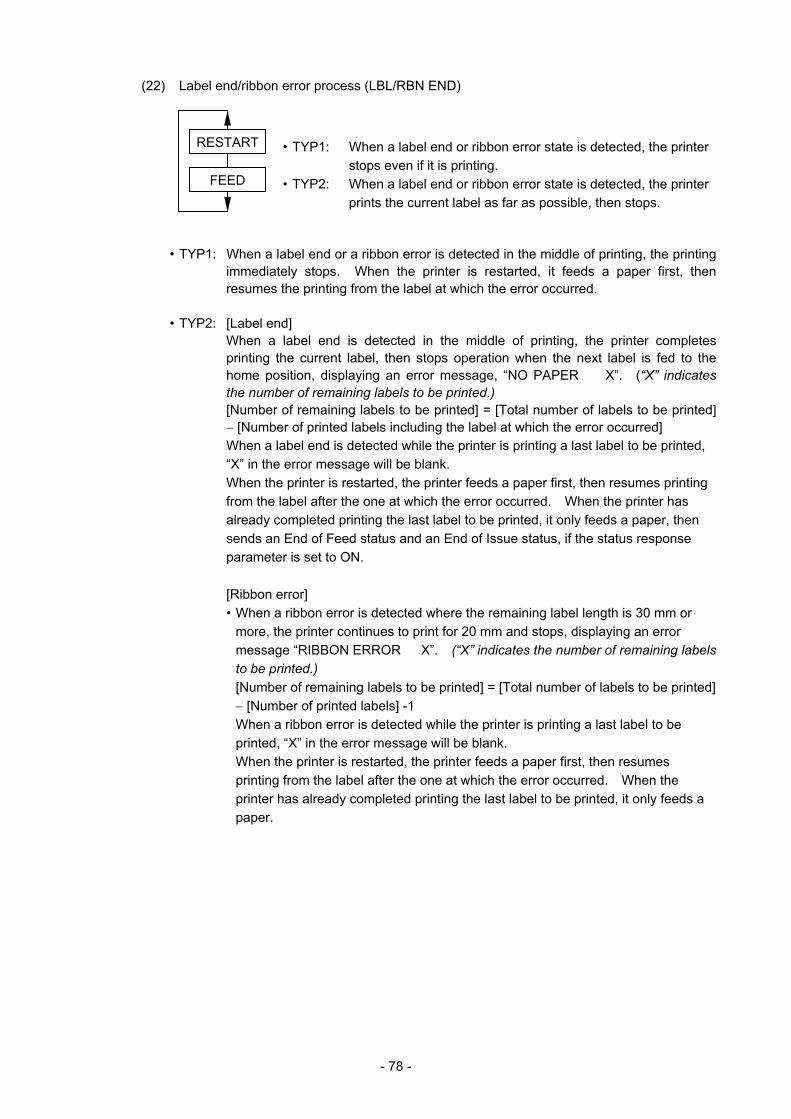
- 78 -
(22) Label end/ribbon error process (LBL/RBN END)
• TYP1: When a label end or ribbon error state is detected, the printer stops even if it is printing.
• TYP2: When a label end or ribbon error state is detected, the printer prints the current label as far as possible, then stops.
• TYP1: When a label end or a ribbon error is detected in the middle of printing, the printing immediately stops. When the printer is restarted, it feeds a paper first, then resumes the printing from the label at which the error occurred.
• TYP2: [Label end]
When a label end is detected in the middle of printing, the printer completes printing the current label, then stops operation when the next label is fed to the home position, displaying an error message, “NO PAPER X”. (“X” indicates the number of remaining labels to be printed.) [Number of remaining labels to be printed] = [Total number of labels to be printed] − [Number of printed labels including the label at which the error occurred] When a label end is detected while the printer is printing a last label to be printed, “X” in the error message will be blank. When the printer is restarted, the printer feeds a paper first, then resumes printing from the label after the one at which the error occurred. When the printer has already completed printing the last label to be printed, it only feeds a paper, then sends an End of Feed status and an End of Issue status, if the status response parameter is set to ON.
[Ribbon error] • When a ribbon error is detected where the remaining label length is 30 mm or
more, the printer continues to print for 20 mm and stops, displaying an error message “RIBBON ERROR X”. (“X” indicates the number of remaining labels to be printed.) [Number of remaining labels to be printed] = [Total number of labels to be printed] − [Number of printed labels] -1 When a ribbon error is detected while the printer is printing a last label to be printed, “X” in the error message will be blank. When the printer is restarted, the printer feeds a paper first, then resumes printing from the label after the one at which the error occurred. When the printer has already completed printing the last label to be printed, it only feeds a paper.
FEED
RESTART

- 79 -
• When a ribbon error is detected where the remaining label length is less than 30 mm, the printer completes printing the current label, then stops operation when the next label is fed to the home position, displaying an error message, “RIBBON ERROR X”. (“X” indicates the number of remaining labels to be printed.) [Number of remaining labels to be printed] = [Total number of labels to be printed] − [Number of printed labels including the label at which the error occurred] When a ribbon error is detected while the printer is printing a last label to be printed, “X” in the error message will be blank. When the printer is restarted, the printer feeds a paper first, then resumes printing from the label after the one at which the error occurred. When the printer has already completed printing the last label to be printed, it only feeds a paper, then sends an End of Feed status and an End of Issue status, if the status response parameter is set to ON.
Examples of LBL/RBN END TYP2
[Case 1] Number of total labels to be printed = 5 A label end is detected while the 3rd label is printed.
(1st)(2nd)(3rd) ↑ After issuing the 3rd label completely, the printer stops, displaying
“NO PAPER 2”.
When the printer is restarted, the printer feeds a paper, then prints on the 4th and 5th labels. All 5 labels are printed.
[Case 2] Number of total labels to be printed = 5 A ribbon error is detected while the 3rd label is printed. The remaining label length is 30 mm or more.
(1st)(2nd)(3rd) ↑ After the 3rd label is printed for 20 mm, the printer stops printing,
displaying “RIBBON ERROR 2”.
When the printer is restarted, the printer fees a paper, then prints on the 4th and 5th labels. The 1st, 2nd, 4th, and 5th labels are printed.
[Case 3] Number of total labels to be printed = 5 A ribbon error is detected while the 3rd label is printed. The remaining label length is less than 30 mm.
(1st)(2nd)(3rd) ↑ After issuing the 3rd label completely, the printer stops, displaying
“RIBBON ERROR 2”.
When the printer is restarted, the printer feeds a paper, then prints on the 4th and 5th labels. All 5 labels are printed.
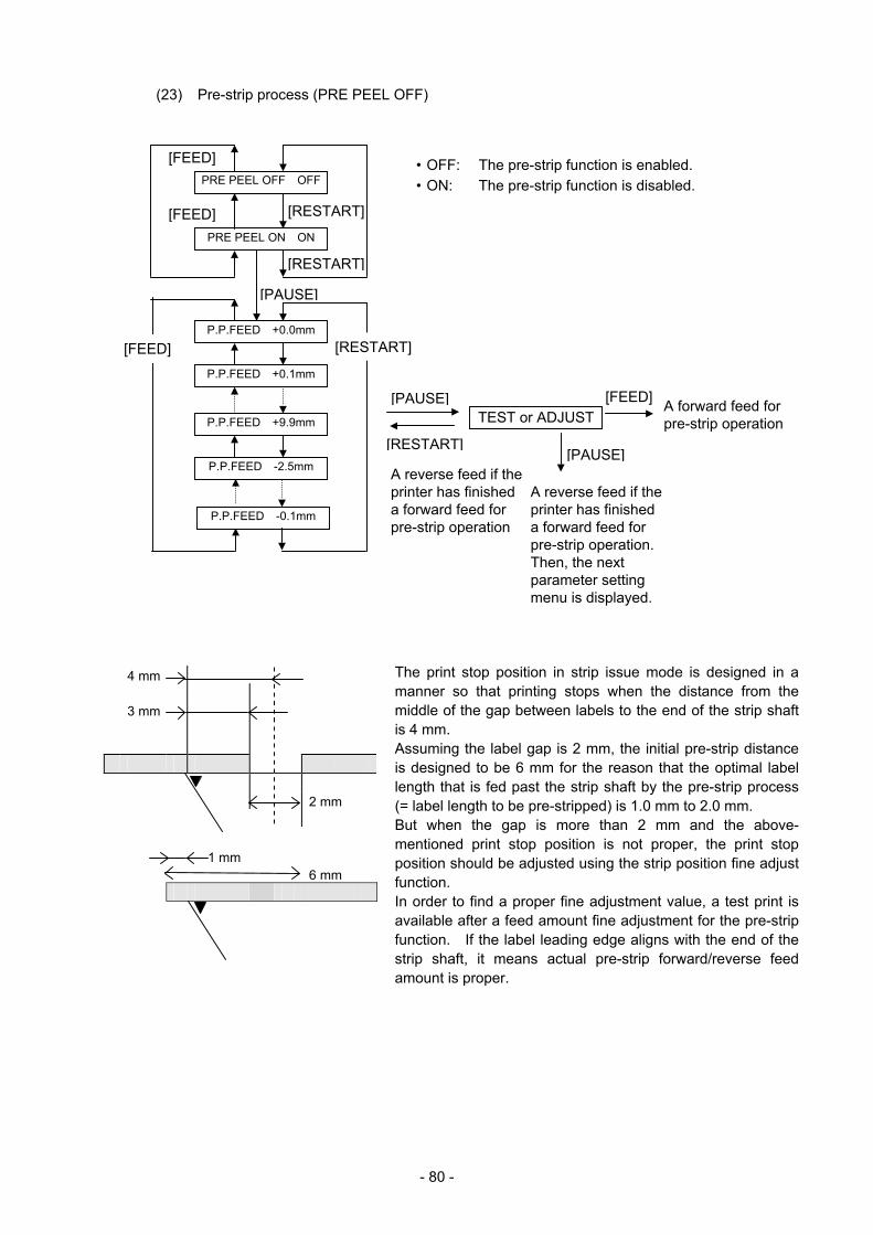
- 80 -
(23) Pre-strip process (PRE PEEL OFF)
• OFF: The pre-strip function is enabled. • ON: The pre-strip function is disabled.
4 mm 3 mm 2 mm
1 mm 6 mm
PRE PEEL OFF OFF
PRE PEEL ON ON
P.P.FEED +0.0mm
P.P.FEED +0.1mm
P.P.FEED +9.9mm
P.P.FEED -2.5mm
P.P.FEED -0.1mm
TEST or ADJUST[PAUSE]
[PAUSE]
[RESTART]
[RESTART]
[FEED]
[RESTART][FEED]
[FEED]
[PAUSE]
The print stop position in strip issue mode is designed in a manner so that printing stops when the distance from the middle of the gap between labels to the end of the strip shaft is 4 mm. Assuming the label gap is 2 mm, the initial pre-strip distance is designed to be 6 mm for the reason that the optimal labellength that is fed past the strip shaft by the pre-strip process (= label length to be pre-stripped) is 1.0 mm to 2.0 mm. But when the gap is more than 2 mm and the above-mentioned print stop position is not proper, the print stop position should be adjusted using the strip position fine adjustfunction. In order to find a proper fine adjustment value, a test print is available after a feed amount fine adjustment for the pre-strip function. If the label leading edge aligns with the end of thestrip shaft, it means actual pre-strip forward/reverse feed amount is proper.
A reverse feed if the printer has finished a forward feed for pre-strip operation
A reverse feed if the printer has finished a forward feed for pre-strip operation. Then, the next parameter setting menu is displayed.
A forward feed for pre-strip operation
[FEED]
[RESTART]
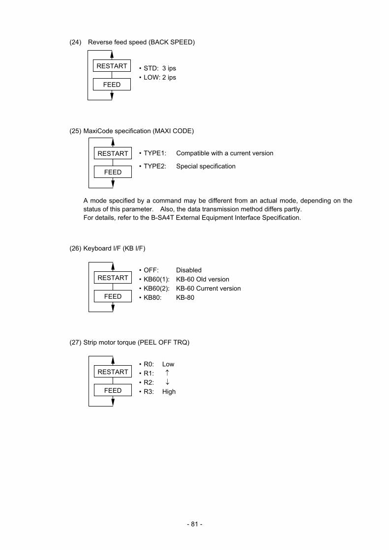
- 81 -
(24) Reverse feed speed (BACK SPEED)
• STD: 3 ips • LOW: 2 ips
(25) MaxiCode specification (MAXI CODE)
• TYPE1: Compatible with a current version
• TYPE2: Special specification
A mode specified by a command may be different from an actual mode, depending on the status of this parameter. Also, the data transmission method differs partly. For details, refer to the B-SA4T External Equipment Interface Specification.
(26) Keyboard I/F (KB I/F)
• OFF: Disabled • KB60(1): KB-60 Old version • KB60(2): KB-60 Current version • KB80: KB-80 (27) Strip motor torque (PEEL OFF TRQ)
• R0: Low • R1: ↑ • R2: ↓ • R3: High
FEED
RESTART
FEED
RESTART
FEED
RESTART
FEED
RESTART
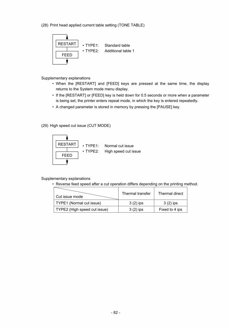
- 82 -
(28) Print head applied current table setting (TONE TABLE)
• TYPE1: Standard table • TYPE2: Additional table 1 Supplementary explanations • When the [RESTART] and [FEED] keys are pressed at the same time, the display
returns to the System mode menu display. • If the [RESTART] or [FEED] key is held down for 0.5 seconds or more when a parameter
is being set, the printer enters repeat mode, in which the key is entered repeatedly. • A changed parameter is stored in memory by pressing the [PAUSE] key. (29) High speed cut issue (CUT MODE)
• TYPE1: Normal cut issue • TYPE2: High speed cut issue Supplementary explanations • Reverse feed speed after a cut operation differs depending on the printing method.
Cut issue mode
Thermal transfer Thermal direct
TYPE1 (Normal cut issue) 3 (2) ips 3 (2) ips TYPE2 (High speed cut issue) 3 (2) ips Fixed to 4 ips
FEED
RESTART
FEED
RESTART
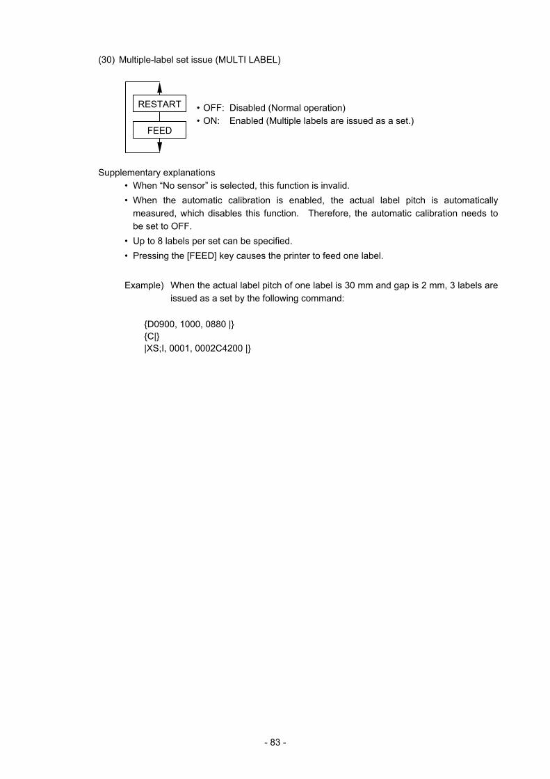
- 83 -
(30) Multiple-label set issue (MULTI LABEL)
• OFF: Disabled (Normal operation) • ON: Enabled (Multiple labels are issued as a set.) Supplementary explanations • When “No sensor” is selected, this function is invalid. • When the automatic calibration is enabled, the actual label pitch is automatically
measured, which disables this function. Therefore, the automatic calibration needs to be set to OFF.
• Up to 8 labels per set can be specified. • Pressing the [FEED] key causes the printer to feed one label.
Example) When the actual label pitch of one label is 30 mm and gap is 2 mm, 3 labels are issued as a set by the following command:
{D0900, 1000, 0880 |} {C|} |XS;I, 0001, 0002C4200 |}
FEED
RESTART
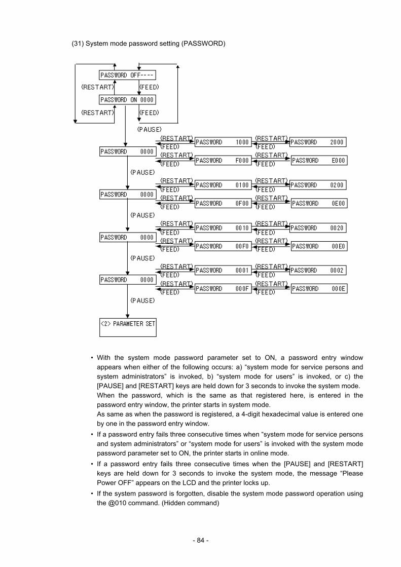
- 84 -
(31) System mode password setting (PASSWORD)
• With the system mode password parameter set to ON, a password entry window
appears when either of the following occurs: a) “system mode for service persons and system administrators” is invoked, b) “system mode for users” is invoked, or c) the [PAUSE] and [RESTART] keys are held down for 3 seconds to invoke the system mode. When the password, which is the same as that registered here, is entered in the password entry window, the printer starts in system mode. As same as when the password is registered, a 4-digit hexadecimal value is entered one by one in the password entry window.
• If a password entry fails three consecutive times when “system mode for service persons and system administrators” or “system mode for users” is invoked with the system mode password parameter set to ON, the printer starts in online mode.
• If a password entry fails three consecutive times when the [PAUSE] and [RESTART] keys are held down for 3 seconds to invoke the system mode, the message “Please Power OFF” appears on the LCD and the printer locks up.
• If the system password is forgotten, disable the system mode password operation using the @010 command. (Hidden command)
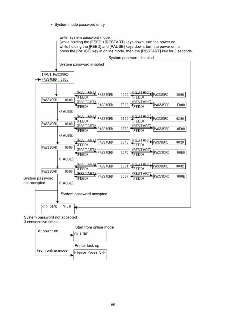
- 85 -
• System mode password entry
Enter system password mode (while holding the [FEED]+[RESTART] keys down, turn the power on, while holding the [FEED] and [PAUSE] keys down, turn the power on, or press the [PAUSE] key in online mode, then the [RESTART] key for 3 seconds.
System password enabled
System password disabled
System password accepted
System password not accepted
At power on
From online mode
Start from online mode
Printer lock-up
System password not accepted 3 consecutive times
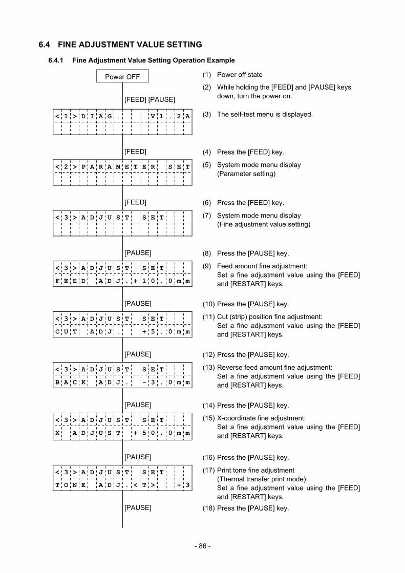
- 86 -
6.4 FINE ADJUSTMENT VALUE SETTING
6.4.1 Fine Adjustment Value Setting Operation Example
Power OFF (1) Power off state
[FEED] [PAUSE]
(2) While holding the [FEED] and [PAUSE] keys down, turn the power on.
< 1 > D I A G . V 1 . 2 A (3) The self-test menu is displayed.
[FEED] (4) Press the [FEED] key.
< 2 > P A R A M E T E R S E T
(5) System mode menu display (Parameter setting)
[FEED] (6) Press the [FEED] key.
< 3 > A D J U S T S E T
(7) System mode menu display (Fine adjustment value setting)
[PAUSE] (8) Press the [PAUSE] key.
< 3 > A D J U S T S E T F E E D A D J . + 1 0 . 0 m m
(9) Feed amount fine adjustment: Set a fine adjustment value using the [FEED]
and [RESTART] keys.
[PAUSE] (10) Press the [PAUSE] key.
< 3 > A D J U S T S E T C U T A D J . + 5 . 0 m m
(11) Cut (strip) position fine adjustment: Set a fine adjustment value using the [FEED]
and [RESTART] keys.
[PAUSE] (12) Press the [PAUSE] key.
< 3 > A D J U S T S E T B A C K A D J . - 3 . 0 m m
(13) Reverse feed amount fine adjustment: Set a fine adjustment value using the [FEED]
and [RESTART] keys.
[PAUSE] (14) Press the [PAUSE] key.
< 3 > A D J U S T S E T X A D J U S T + 5 0 . 0 m m
(15) X-coordinate fine adjustment: Set a fine adjustment value using the [FEED]
and [RESTART] keys.
[PAUSE] (16) Press the [PAUSE] key.
< 3 > A D J U S T S E T T O N E A D J . < T > + 3
(17) Print tone fine adjustment (Thermal transfer print mode):
Set a fine adjustment value using the [FEED] and [RESTART] keys.
[PAUSE] (18) Press the [PAUSE] key.
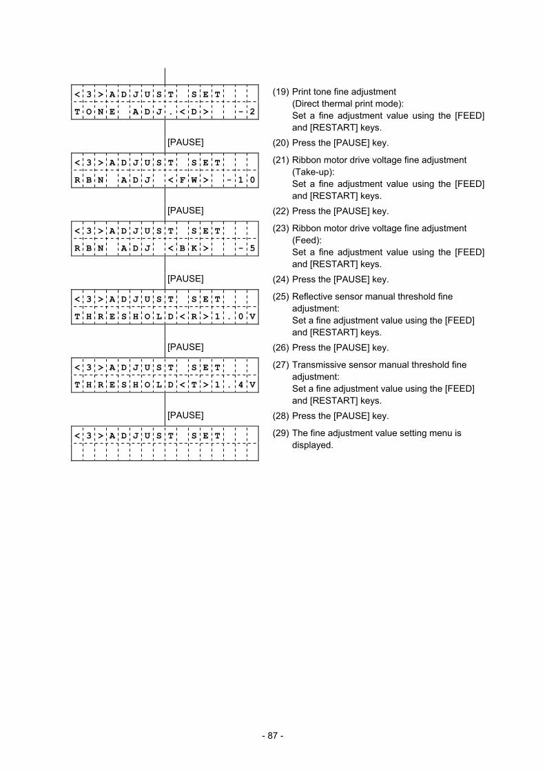
- 87 -
< 3 > A D J U S T S E T T O N E A D J . < D > - 2
(19) Print tone fine adjustment (Direct thermal print mode):
Set a fine adjustment value using the [FEED] and [RESTART] keys.
[PAUSE] (20) Press the [PAUSE] key.
< 3 > A D J U S T S E T R B N A D J < F W > - 1 0
(21) Ribbon motor drive voltage fine adjustment (Take-up):
Set a fine adjustment value using the [FEED] and [RESTART] keys.
[PAUSE] (22) Press the [PAUSE] key.
< 3 > A D J U S T S E T R B N A D J < B K > - 5
(23) Ribbon motor drive voltage fine adjustment (Feed):
Set a fine adjustment value using the [FEED] and [RESTART] keys.
[PAUSE] (24) Press the [PAUSE] key.
< 3 > A D J U S T S E T T H R E S H O L D < R > 1 . 0 V
(25) Reflective sensor manual threshold fine adjustment:
Set a fine adjustment value using the [FEED] and [RESTART] keys.
[PAUSE] (26) Press the [PAUSE] key.
< 3 > A D J U S T S E T T H R E S H O L D < T > 1 . 4 V
(27) Transmissive sensor manual threshold fine adjustment: Set a fine adjustment value using the [FEED] and [RESTART] keys.
[PAUSE] (28) Press the [PAUSE] key.
< 3 > A D J U S T S E T
(29) The fine adjustment value setting menu is displayed.

- 88 -
6.4.2 Details of Fine Adjustment Value Setting
(1) Feed amount fine adjustment (FEED ADJ.)
(2) Cut (strip) position fine adjustment (CUT ADJ.)
+0.0 mm
+3.0 mm
-3.0 mm
Cut position
Paper feed direction
Cut position
Cut position
+50.0 mm+49.9 mm
+0.1 mm+0.0 mm-0.1 mm
+49.9 mm+50.0 mm
FEED
RESTART
+0.0 mm
+3.0 mm
Print start position
One label
One label
Print start position
-3.0 mm
One label Print start position
Paper feed direction
FEED
RESTART
+50.0 mm+49.9 mm
+0.1 mm+0.0 mm-0.1 mm
+49.9 mm+50.0 mm
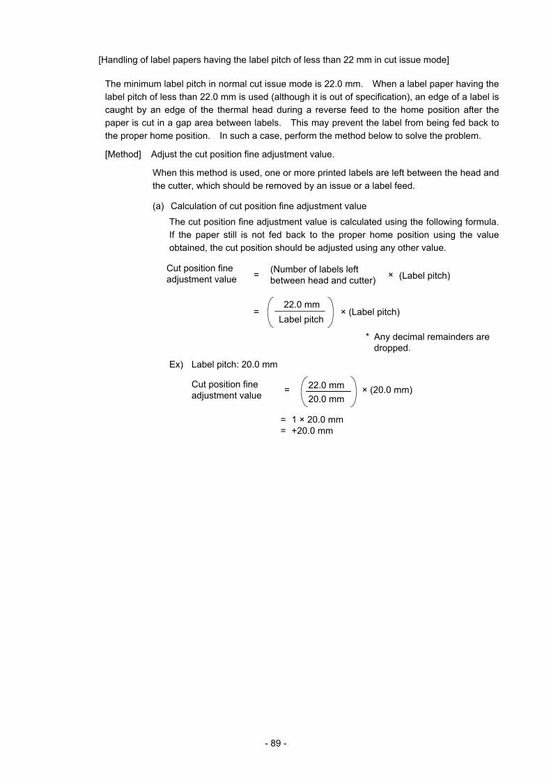
- 89 -
[Handling of label papers having the label pitch of less than 22 mm in cut issue mode]
The minimum label pitch in normal cut issue mode is 22.0 mm. When a label paper having the label pitch of less than 22.0 mm is used (although it is out of specification), an edge of a label is caught by an edge of the thermal head during a reverse feed to the home position after the paper is cut in a gap area between labels. This may prevent the label from being fed back to the proper home position. In such a case, perform the method below to solve the problem.
[Method] Adjust the cut position fine adjustment value.
When this method is used, one or more printed labels are left between the head and the cutter, which should be removed by an issue or a label feed.
(a) Calculation of cut position fine adjustment value
The cut position fine adjustment value is calculated using the following formula. If the paper still is not fed back to the proper home position using the value obtained, the cut position should be adjusted using any other value.
Ex) Label pitch: 20.0 mm
Label pitch
(Label pitch)
22.0 mm
* Any decimal remainders are dropped.
× (Label pitch)
Cut position fine adjustment value =
=
(Number of labels left between head and cutter) ×
22.0 mm20.0 mm
× (20.0 mm) Cut position fine adjustment value =
= 1 × 20.0 mm = +20.0 mm
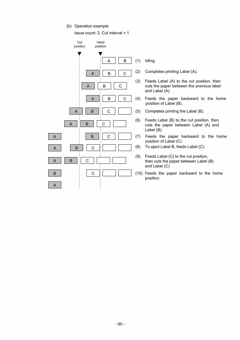
- 90 -
(b) Operation example
Issue count: 2, Cut interval = 1
A
B
A
(1) Idling
Headposition
Cut position
A
(5) Completes printing the Label (B).
(9) Feeds Label (C) to the cut position, then cuts the paper between Label (B) and Label (C)
B
C
(2) Completes printing Label (A).
(3) Feeds Label (A) to the cut position, then cuts the paper between the previous label and Label (A).
(8) To eject Label B, feeds Label (C).
(10) Feeds the paper backward to the home position.
B C
C
A
B
A (4) Feeds the paper backward to the home position of Label (B).
B C
B (6) Feeds Label (B) to the cut position, then
cuts the paper between Label (A) and Label (B).
A
A B (7) Feeds the paper backward to the home position of Label (C).
C
A B C
A B C
C
A
B C

- 91 -
[Strip position fine adjustment]
Assuming the label gap is 2 mm, the print stop position in strip issue mode is designed in a manner so that printing stops when the distance from the middle of the gap between labels to the end of the strip shaft is 4 mm. When the gap is more than 2 mm and the above-mentioned print stop position is not proper, the print stop position should be adjusted using the strip position fine adjust function.
+0.0 mm
+3.0 mm
- 3.0 mm
2 mm
4 mm
3 mm
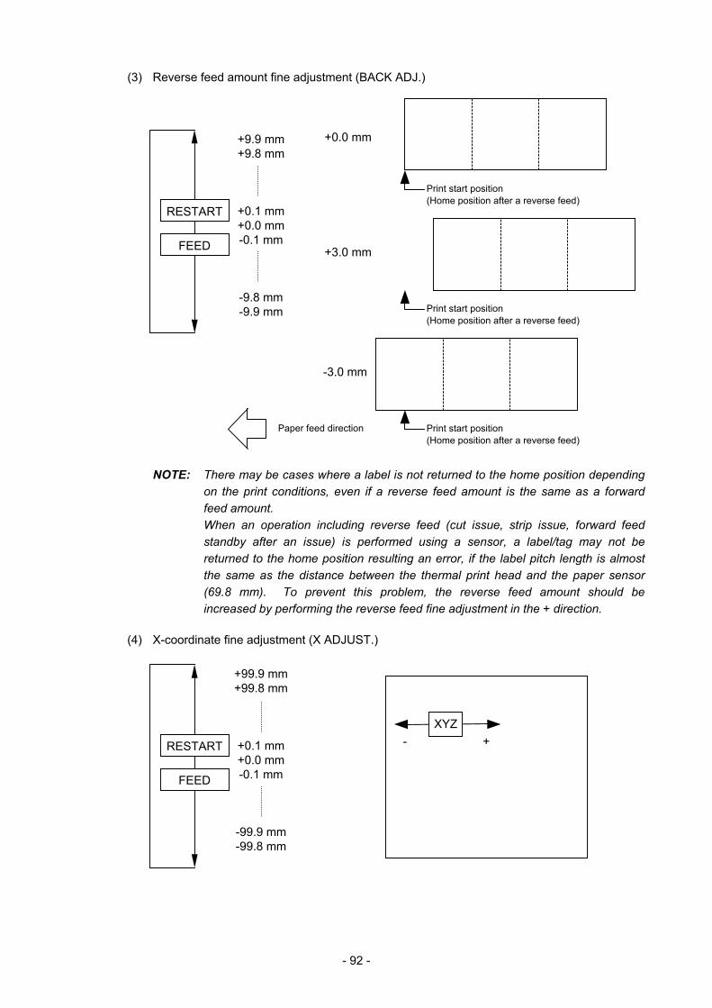
- 92 -
(3) Reverse feed amount fine adjustment (BACK ADJ.)
NOTE: There may be cases where a label is not returned to the home position depending on the print conditions, even if a reverse feed amount is the same as a forward feed amount. When an operation including reverse feed (cut issue, strip issue, forward feed standby after an issue) is performed using a sensor, a label/tag may not be returned to the home position resulting an error, if the label pitch length is almost the same as the distance between the thermal print head and the paper sensor (69.8 mm). To prevent this problem, the reverse feed amount should be increased by performing the reverse feed fine adjustment in the + direction.
(4) X-coordinate fine adjustment (X ADJUST.)
+-XYZ
+99.9 mm +99.8 mm
+0.1 mm +0.0 mm -0.1 mm
-99.9 mm -99.8 mm
FEED
RESTART
+0.0 mm
+3.0 mm
-3.0 mm
Print start position (Home position after a reverse feed)
Paper feed direction
+9.9 mm +9.8 mm
+0.1 mm +0.0 mm -0.1 mm
-9.8 mm -9.9 mm
FEED
RESTART
Print start position (Home position after a reverse feed)
Print start position (Home position after a reverse feed)
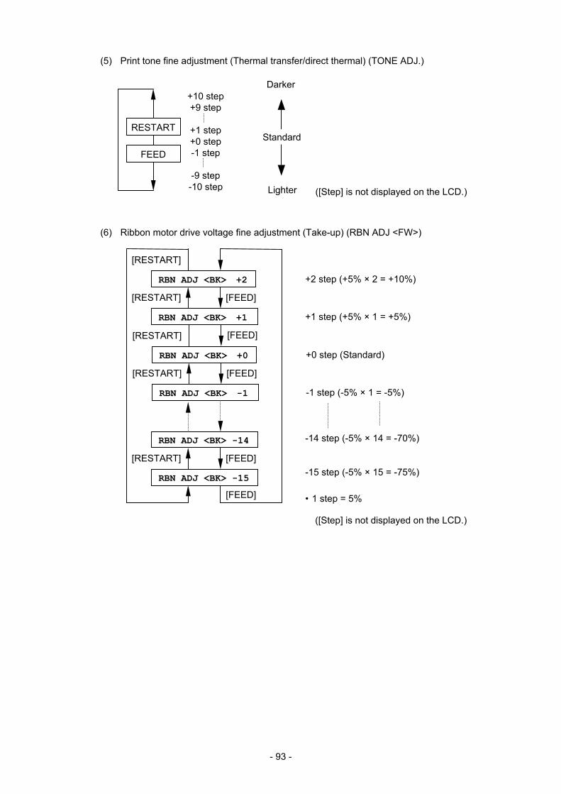
- 93 -
(5) Print tone fine adjustment (Thermal transfer/direct thermal) (TONE ADJ.)
(6) Ribbon motor drive voltage fine adjustment (Take-up) (RBN ADJ <FW>)
Darker
Lighter
Standard
([Step] is not displayed on the LCD.)
+10 step +9 step
+1 step +0 step -1 step
-9 step -10 step
FEED
RESTART
+2 step (+5% × 2 = +10%)
+1 step (+5% × 1 = +5%)
• 1 step = 5%
RBN ADJ <BK> +2
[RESTART]
RBN ADJ <BK> +1
[FEED][RESTART]
RBN ADJ <BK> -14
RBN ADJ <BK> -15
[FEED][RESTART]
[FEED]
-14 step (-5% × 14 = -70%)
-15 step (-5% × 15 = -75%)
([Step] is not displayed on the LCD.)
RBN ADJ <BK> +0
[RESTART]
RBN ADJ <BK> -1
[FEED][RESTART]
[FEED]
+0 step (Standard)
-1 step (-5% × 1 = -5%)
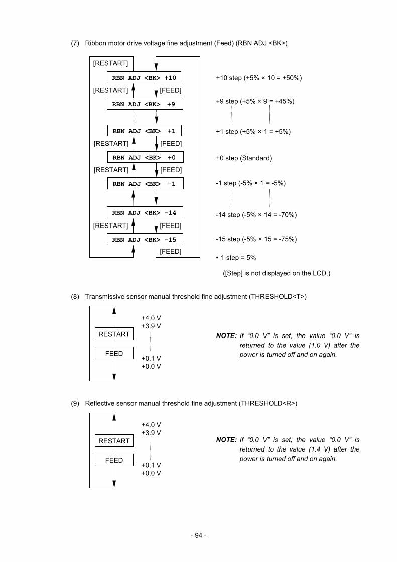
- 94 -
(7) Ribbon motor drive voltage fine adjustment (Feed) (RBN ADJ <BK>)
(8) Transmissive sensor manual threshold fine adjustment (THRESHOLD<T>)
(9) Reflective sensor manual threshold fine adjustment (THRESHOLD<R>)
+4.0 V +3.9 V
+0.1 V +0.0 V
+4.0 V +3.9 V
+0.1 V +0.0 V
NOTE: If “0.0 V” is set, the value “0.0 V” is returned to the value (1.0 V) after the power is turned off and on again.
NOTE: If “0.0 V” is set, the value “0.0 V” is returned to the value (1.4 V) after thepower is turned off and on again.
RBN ADJ <BK> +10
RBN ADJ <BK> +9
[FEED][RESTART]
RBN ADJ <BK> -14
RBN ADJ <BK> -15
[FEED][RESTART]
[RESTART]
[FEED]
+10 step (+5% × 10 = +50%)
+9 step (+5% × 9 = +45%)
• 1 step = 5%
-14 step (-5% × 14 = -70%)
-15 step (-5% × 15 = -75%)
FEED
RESTART
FEED
RESTART
([Step] is not displayed on the LCD.)
RBN ADJ <BK> +1
RBN ADJ <BK> +0
[FEED][RESTART]
RBN ADJ <BK> -1
[FEED][RESTART]
+1 step (+5% × 1 = +5%)
+0 step (Standard)
-1 step (-5% × 1 = -5%)
- 95 -
Supplementary explanations
• When the [RESTART] and [FEED] keys are pressed at the same time, the display shows the system mode menu.
• If the [RESTART] or [FEED] key is held down for 0.5 seconds when a fine adjustment value is being set, the printer enters repeat mode, in which the key is entered repeatedly.
• A changed fine adjustment value is stored in memory by pressing the [PAUSE] key.
• The printer is controlled by a sum of a fine adjustment parameter value programmed on the printer and a fine adjustment command value from the PC. The maximum value for each fine adjustment is as follows:
Feed fine adjustment ....................................................................... ±50.0 mm Strip position fine adjustment .......................................................... ±50.0 mm Back feed fine adjustment ................................................................. ±9.9 mm Print density fine adjustment ............................................................. ±10 step X-coordinate fine adjustment........................................................... ±99.9 mm Ribbon motor drive voltage fine adjustment (Take-up) ............. -15 to +2 step Ribbon motor drive voltage fine adjustment (Feed) ................ -15 to +10 step
• An X-coordinate fine adjustment is performed to finely adjust the X-coordinate of a drawing in the left or right direction in an effective print width range. (Even if a value is set to less than 0 as a result of the fine adjustment, the value is set to 0.)
• An X-coordinate fine adjustment is not effective for self-test print (maintenance counter values, various parameter values, and automatic self-test) and other test print.
• A print tone fine adjustment value is +0 step at the time of shipment from the factory.
• A ribbon take-up/feed motor drive voltage fine adjustment value is a sum of a fine adjustment value by a command (from the PC) and a fine adjustment value in the system mode (by key operation). The maximum fine adjustment value is -15 for both the ribbon take-up motor and the ribbon feed motor.
• A print tone fine adjustment value is a sum of a fine adjustment value by a command (from the PC) and a fine adjustment value in system mode (by key operation). The maximum value for each print speed, 203 dpi and 300 dpi, is as below. When the value exceeds the maximum, it is automatically corrected to the maximum.
203 dpi 300 dpi
Print Speed Thermal direct
Thermal transfer
Thermal direct
Thermal transfer
2 ips +10 step +10 step +10 step +10 step 4 ips +8 step +10 step +8 step +10 step 6 ips +8 step +10 step +8 step +10 step
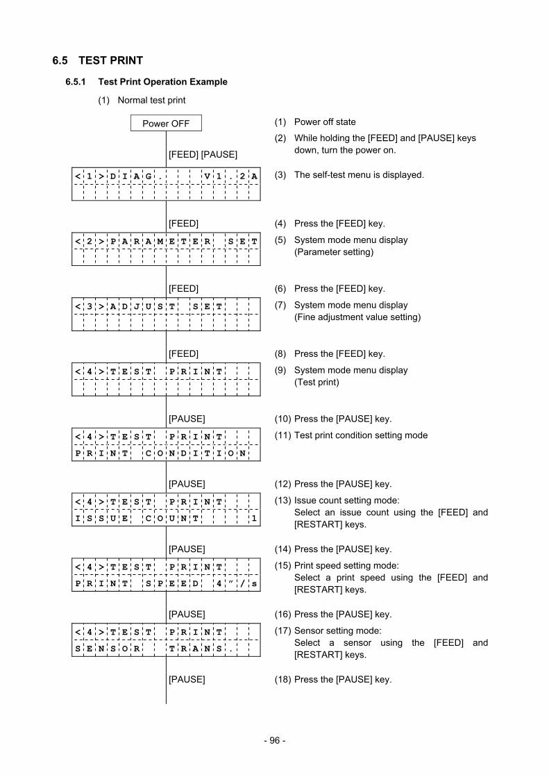
- 96 -
6.5 TEST PRINT
6.5.1 Test Print Operation Example
(1) Normal test print
Power OFF (1) Power off state
[FEED] [PAUSE]
(2) While holding the [FEED] and [PAUSE] keys down, turn the power on.
< 1 > D I A G . V 1 . 2 A
(3) The self-test menu is displayed.
[FEED] (4) Press the [FEED] key.
< 2 > P A R A M E T E R S E T
(5) System mode menu display (Parameter setting)
[FEED] (6) Press the [FEED] key.
< 3 > A D J U S T S E T
(7) System mode menu display (Fine adjustment value setting)
[FEED] (8) Press the [FEED] key.
< 4 > T E S T P R I N T
(9) System mode menu display (Test print)
[PAUSE] (10) Press the [PAUSE] key.
< 4 > T E S T P R I N T
P R I N T C O N D I T I O N
(11) Test print condition setting mode
[PAUSE] (12) Press the [PAUSE] key.
< 4 > T E S T P R I N T
I S S U E C O U N T 1
(13) Issue count setting mode: Select an issue count using the [FEED] and
[RESTART] keys.
[PAUSE] (14) Press the [PAUSE] key.
< 4 > T E S T P R I N T
P R I N T S P E E D 4 ” / s
(15) Print speed setting mode: Select a print speed using the [FEED] and
[RESTART] keys.
[PAUSE] (16) Press the [PAUSE] key.
< 4 > T E S T P R I N T
S E N S O R T R A N S .
(17) Sensor setting mode: Select a sensor using the [FEED] and
[RESTART] keys.
[PAUSE] (18) Press the [PAUSE] key.
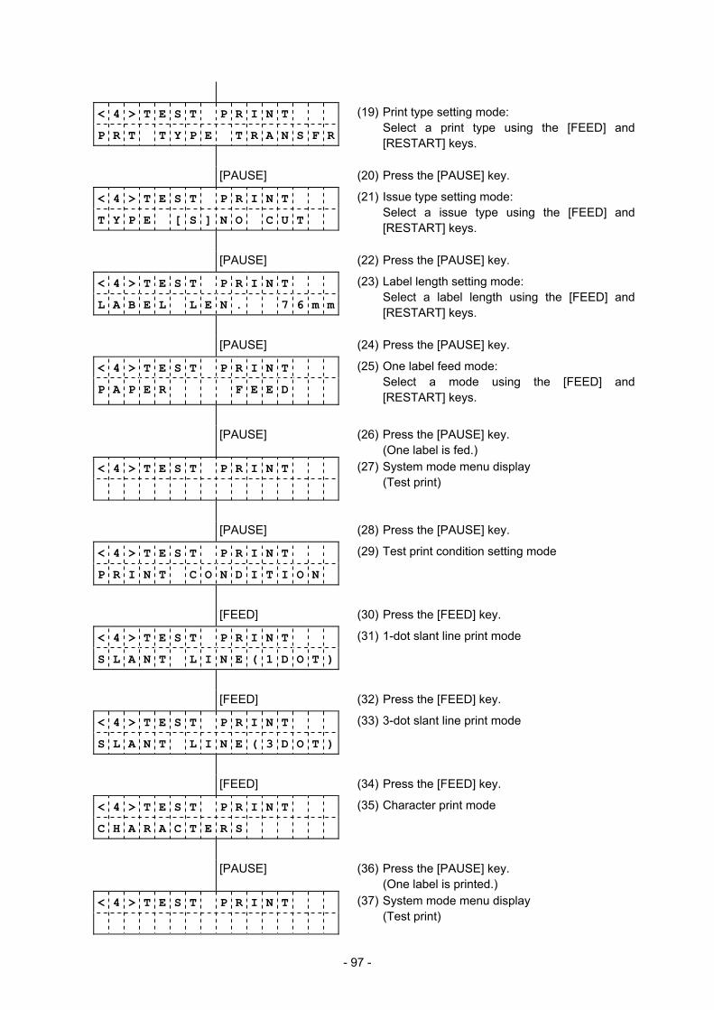
- 97 -
< 4 > T E S T P R I N T
P R T T Y P E T R A N S F R
(19) Print type setting mode: Select a print type using the [FEED] and
[RESTART] keys.
[PAUSE] (20) Press the [PAUSE] key.
< 4 > T E S T P R I N T
T Y P E [ S ] N O C U T
(21) Issue type setting mode: Select a issue type using the [FEED] and
[RESTART] keys.
[PAUSE] (22) Press the [PAUSE] key.
< 4 > T E S T P R I N T
L A B E L L E N . 7 6 m m
(23) Label length setting mode: Select a label length using the [FEED] and
[RESTART] keys.
[PAUSE] (24) Press the [PAUSE] key.
< 4 > T E S T P R I N T
P A P E R F E E D
(25) One label feed mode: Select a mode using the [FEED] and
[RESTART] keys.
[PAUSE] (26) Press the [PAUSE] key. (One label is fed.)
< 4 > T E S T P R I N T
(27) System mode menu display (Test print)
[PAUSE] (28) Press the [PAUSE] key.
< 4 > T E S T P R I N T
P R I N T C O N D I T I O N
(29) Test print condition setting mode
[FEED] (30) Press the [FEED] key.
< 4 > T E S T P R I N T
S L A N T L I N E ( 1 D O T )
(31) 1-dot slant line print mode
[FEED] (32) Press the [FEED] key.
< 4 > T E S T P R I N T
S L A N T L I N E ( 3 D O T )
(33) 3-dot slant line print mode
[FEED] (34) Press the [FEED] key.
< 4 > T E S T P R I N T
C H A R A C T E R S
(35) Character print mode
[PAUSE] (36) Press the [PAUSE] key. (One label is printed.)
< 4 > T E S T P R I N T
(37) System mode menu display (Test print)
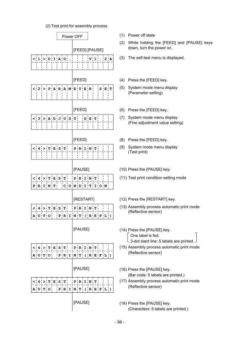
- 98 -
(2) Test print for assembly process
Power OFF (1) Power off state
[FEED] [PAUSE]
(2) While holding the [FEED] and [PAUSE] keys down, turn the power on.
< 1 > D I A G . V 1 . 2 A
(3) The self-test menu is displayed.
[FEED] (4) Press the [FEED] key.
< 2 > P A R A M E T E R S E T
(5) System mode menu display (Parameter setting)
[FEED] (6) Press the [FEED] key.
< 3 > A D J U S T S E T
(7) System mode menu display (Fine adjustment value setting)
[FEED] (8) Press the [FEED] key.
< 4 > T E S T P R I N T
(9) System mode menu display (Test print)
[PAUSE] (10) Press the [PAUSE] key.
< 4 > T E S T P R I N T
P R I N T C O N D I T I O N
(11) Test print condition setting mode
[RESTART] (12) Press the [RESTART] key.
< 4 > T E S T P R I N T
A U T O P R I N T ( R E F L )
(13) Assembly process automatic print mode (Reflective sensor)
[PAUSE] (14) Press the [PAUSE] key. One label is fed.
3-dot slant line: 5 labels are printed. < 4 > T E S T P R I N T
A U T O P R I N T ( R E F L )
(15) Assembly process automatic print mode (Reflective sensor)
[PAUSE] (16) Press the [PAUSE] key. (Bar code: 5 labels are printed.)
< 4 > T E S T P R I N T
A U T O P R I N T ( R E F L )
(17) Assembly process automatic print mode (Reflective sensor)
[PAUSE] (18) Press the [PAUSE] key. (Characters: 5 labels are printed.)
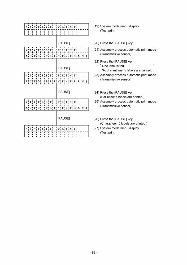
- 99 -
< 4 > T E S T P R I N T
(19) System mode menu display (Test print)
[PAUSE] (20) Press the [PAUSE] key.
< 4 > T E S T P R I N T
A U T O P R I N T ( T R A N )
(21) Assembly process automatic print mode (Transmissive sensor)
[PAUSE]
(22) Press the [PAUSE] key. One label is fed.
3-dot slant line: 5 labels are printed. < 4 > T E S T P R I N T
A U T O P R I N T ( T R A N )
(23) Assembly process automatic print mode (Transmissive sensor)
[PAUSE] (24) Press the [PAUSE] key. (Bar code: 5 labels are printed.)
< 4 > T E S T P R I N T
A U T O P R I N T ( T R A N )
(25) Assembly process automatic print mode (Transmissive sensor)
[PAUSE] (26) Press the [PAUSE] key. (Characters: 5 labels are printed.)
< 4 > T E S T P R I N T
(27) System mode menu display (Test print)

- 100 -
6.5.2 Details of Test Print Setting
(1) Test print mode
• PRINT CONDITION (Test print condition parameters) • SLANT LINE(1DOT) (1-dot slant line print) • SLANT LINE(3DOT) (3-dot slant line print) • CHARACTERS (Character print) • BARCODE (Bar code print) • NON-PRINTING (Nothing prints.) • FACTORY TEST (Line print for assembly process) • AUTO PRINT(TRAN) (Assembly process automatic
print/transmissive sensor) • AUTO PRINT(REFL) (Assembly process automatic print/reflective
sensor) (2) Test print condition parameters (PRINT CONDITION)
• ISSUE COUNT (Issue count) • PRINT SPEED (Print speed) • SENSOR (Sensor) • PRT TYPE (Print method) • TYPE (Issue mode) • LABEL LEN. (Label length) • PAPER FEED (Paper feed mode) • <4> TEST PRINT (Test print mode) • PRINT CONDITION (Test print condition parameters)
(3) Issue count (ISSUE COUNT)
• 5000 (Issue count: 5000) • 1000 (Issue count: 1000) • 500 (Issue count: 500) • 100 (Issue count: 100) • 50 (Issue count: 50) • 10 (Issue count: 10) • 5 (Issue count: 5) • 3 (Issue count: 3) • 1 (Issue count: 1)
(4) Print speed (PRINT SPEED)
• 6 ips (6 inches/sec) • 4 ips (4 inches/sec) • 2 ips (2 inches/sec)
FEED
RESTART
PAUSE
FEED
RESTART
FEED
RESTART
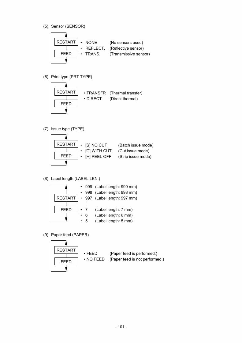
- 101 -
(5) Sensor (SENSOR)
• NONE (No sensors used) • REFLECT. (Reflective sensor) • TRANS. (Transmissive sensor) (6) Print type (PRT TYPE)
• TRANSFR (Thermal transfer) • DIRECT (Direct thermal)
(7) Issue type (TYPE)
• [S] NO CUT (Batch issue mode) • [C] WITH CUT (Cut issue mode) • [H] PEEL OFF (Strip issue mode)
(8) Label length (LABEL LEN.)
• 999 (Label length: 999 mm) • 998 (Label length: 998 mm) • 997 (Label length: 997 mm) • 7 (Label length: 7 mm) • 6 (Label length: 6 mm) • 5 (Label length: 5 mm)
(9) Paper feed (PAPER)
• FEED (Paper feed is performed.) • NO FEED (Paper feed is not performed.)
FEED
RESTART
FEED
RESTART
FEED
RESTART
FEED
RESTART
FEED
RESTART
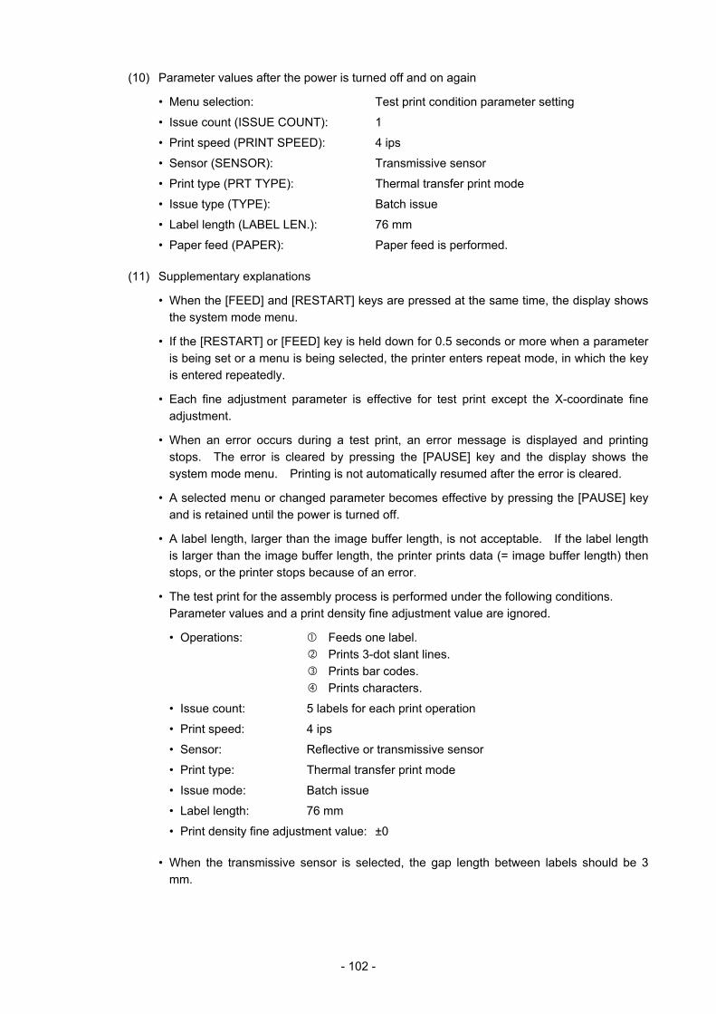
- 102 -
(10) Parameter values after the power is turned off and on again
• Menu selection: Test print condition parameter setting
• Issue count (ISSUE COUNT): 1
• Print speed (PRINT SPEED): 4 ips
• Sensor (SENSOR): Transmissive sensor
• Print type (PRT TYPE): Thermal transfer print mode
• Issue type (TYPE): Batch issue
• Label length (LABEL LEN.): 76 mm
• Paper feed (PAPER): Paper feed is performed.
(11) Supplementary explanations
• When the [FEED] and [RESTART] keys are pressed at the same time, the display shows the system mode menu.
• If the [RESTART] or [FEED] key is held down for 0.5 seconds or more when a parameter is being set or a menu is being selected, the printer enters repeat mode, in which the key is entered repeatedly.
• Each fine adjustment parameter is effective for test print except the X-coordinate fine adjustment.
• When an error occurs during a test print, an error message is displayed and printing stops. The error is cleared by pressing the [PAUSE] key and the display shows the system mode menu. Printing is not automatically resumed after the error is cleared.
• A selected menu or changed parameter becomes effective by pressing the [PAUSE] key and is retained until the power is turned off.
• A label length, larger than the image buffer length, is not acceptable. If the label length is larger than the image buffer length, the printer prints data (= image buffer length) then stops, or the printer stops because of an error.
• The test print for the assembly process is performed under the following conditions. Parameter values and a print density fine adjustment value are ignored.
• Operations: Feeds one label. Prints 3-dot slant lines. Prints bar codes. Prints characters.
• Issue count: 5 labels for each print operation
• Print speed: 4 ips
• Sensor: Reflective or transmissive sensor
• Print type: Thermal transfer print mode
• Issue mode: Batch issue
• Label length: 76 mm
• Print density fine adjustment value: ±0
• When the transmissive sensor is selected, the gap length between labels should be 3 mm.
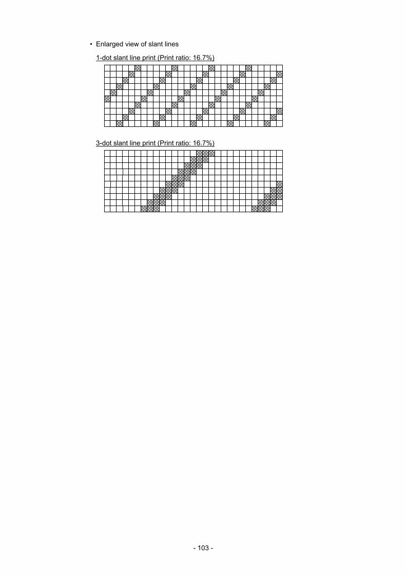
- 103 -
• Enlarged view of slant lines
1-dot slant line print (Print ratio: 16.7%)
3-dot slant line print (Print ratio: 16.7%)
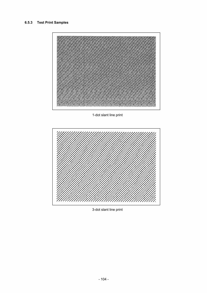
- 104 -
6.5.3 Test Print Samples
1-dot slant line print
3-dot slant line print
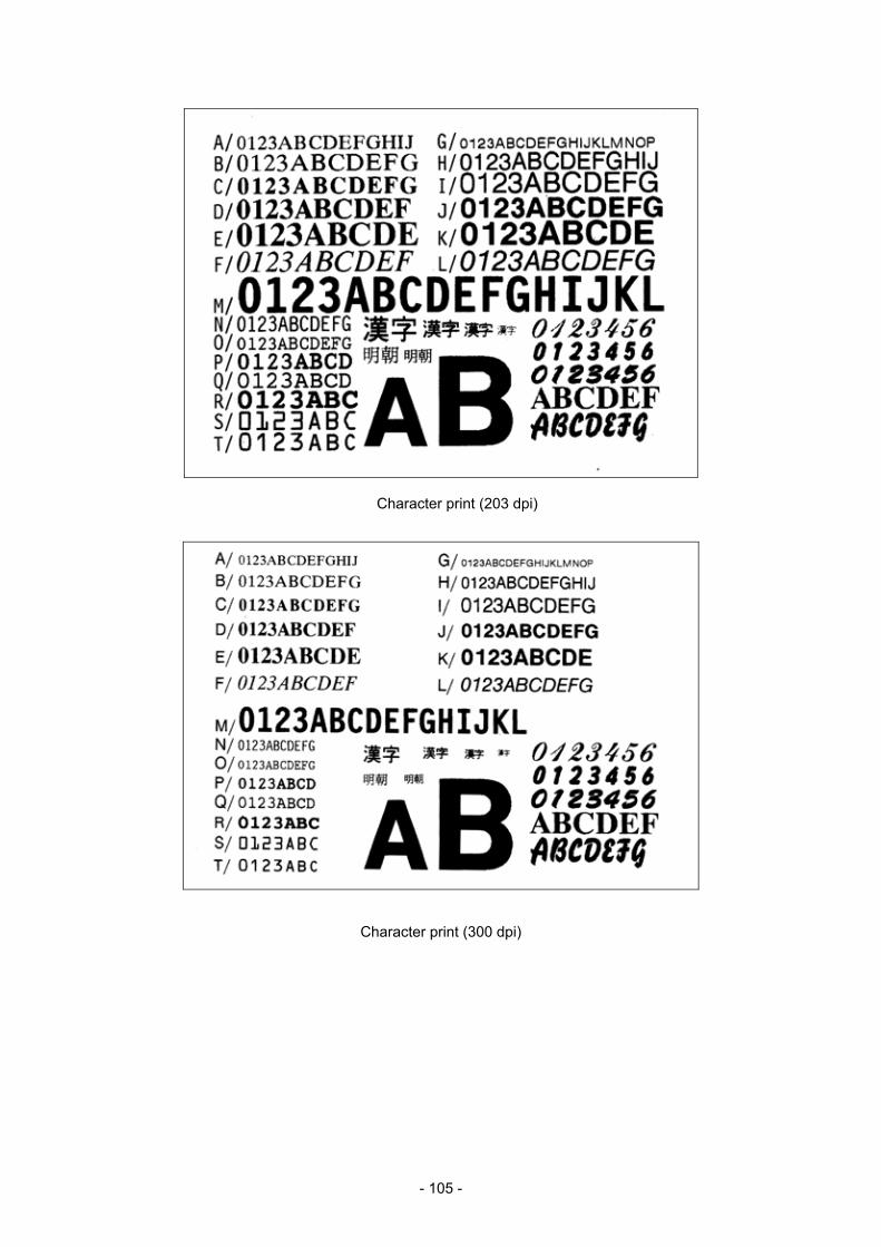
- 105 -
Character print (203 dpi)
Character print (300 dpi)
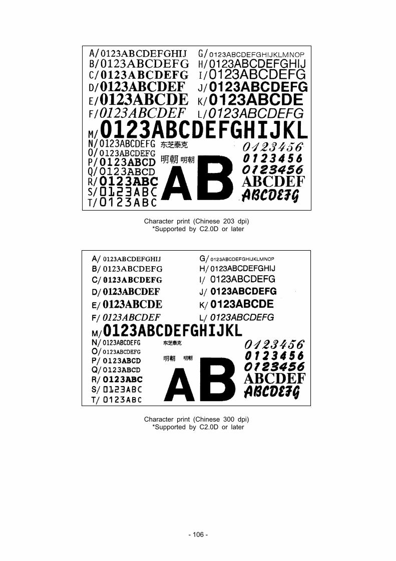
- 106 -
Character print (Chinese 203 dpi) *Supported by C2.0D or later
Character print (Chinese 300 dpi) *Supported by C2.0D or later
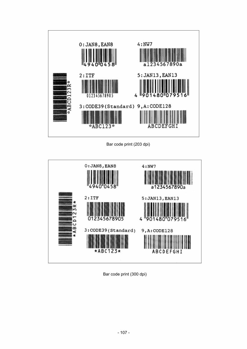
- 107 -
Bar code print (203 dpi)
Bar code print (300 dpi)
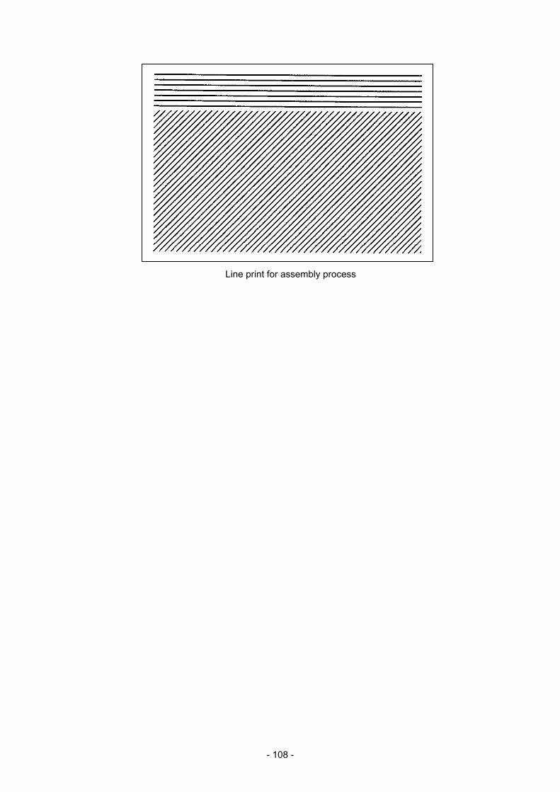
- 108 -
Line print for assembly process
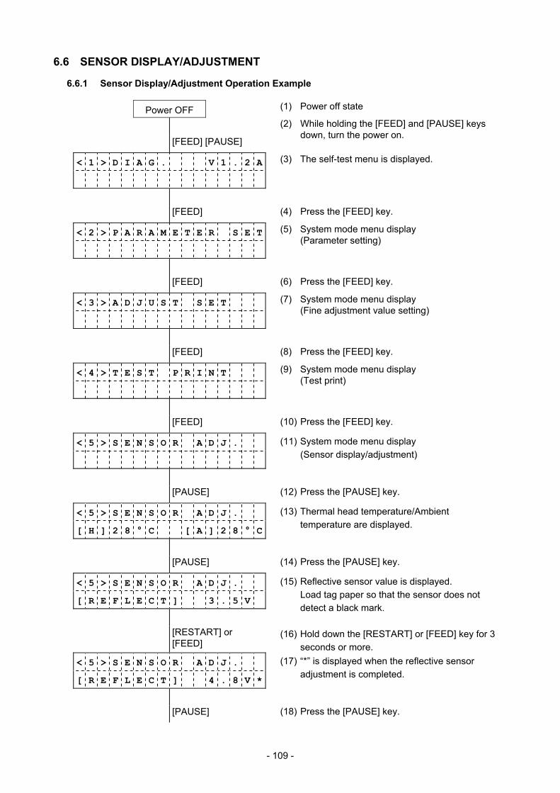
- 109 -
6.6 SENSOR DISPLAY/ADJUSTMENT
6.6.1 Sensor Display/Adjustment Operation Example
Power OFF (1) Power off state
[FEED] [PAUSE]
(2) While holding the [FEED] and [PAUSE] keys down, turn the power on.
< 1 > D I A G . V 1 . 2 A
(3) The self-test menu is displayed.
[FEED] (4) Press the [FEED] key.
< 2 > P A R A M E T E R S E T
(5) System mode menu display (Parameter setting)
[FEED] (6) Press the [FEED] key.
< 3 > A D J U S T S E T
(7) System mode menu display (Fine adjustment value setting)
[FEED] (8) Press the [FEED] key.
< 4 > T E S T P R I N T
(9) System mode menu display (Test print)
[FEED] (10) Press the [FEED] key.
< 5 > S E N S O R A D J .
(11) System mode menu display (Sensor display/adjustment)
[PAUSE] (12) Press the [PAUSE] key.
< 5 > S E N S O R A D J .
[ H ] 2 8 ° C [ A ] 2 8 ° C
(13) Thermal head temperature/Ambient temperature are displayed.
[PAUSE] (14) Press the [PAUSE] key.
< 5 > S E N S O R A D J .
[ R E F L E C T ] 3 . 5 V
(15) Reflective sensor value is displayed. Load tag paper so that the sensor does not
detect a black mark.
[RESTART] or [FEED]
(16) Hold down the [RESTART] or [FEED] key for 3 seconds or more.
< 5 > S E N S O R A D J .
[ R E F L E C T ] 4 . 8 V *
(17) “*” is displayed when the reflective sensor adjustment is completed.
[PAUSE] (18) Press the [PAUSE] key.
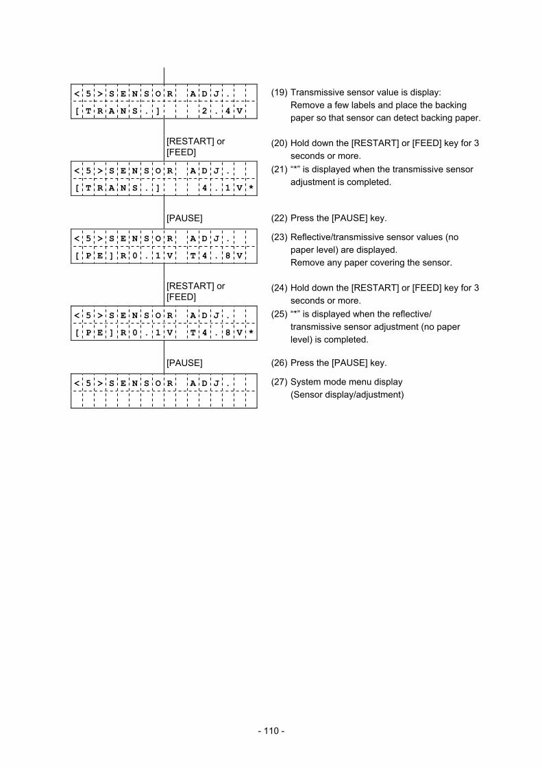
- 110 -
< 5 > S E N S O R A D J .
[ T R A N S . ] 2 . 4 V
(19) Transmissive sensor value is display: Remove a few labels and place the backing paper so that sensor can detect backing paper.
[RESTART] or [FEED]
(20) Hold down the [RESTART] or [FEED] key for 3 seconds or more.
< 5 > S E N S O R A D J .
[ T R A N S . ] 4 . 1 V *
(21) “*” is displayed when the transmissive sensor adjustment is completed.
[PAUSE] (22) Press the [PAUSE] key.
< 5 > S E N S O R A D J .
[ P E ] R 0 . 1 V T 4 . 8 V
(23) Reflective/transmissive sensor values (no paper level) are displayed.
Remove any paper covering the sensor.
[RESTART] or [FEED]
(24) Hold down the [RESTART] or [FEED] key for 3 seconds or more.
< 5 > S E N S O R A D J .
[ P E ] R 0 . 1 V T 4 . 8 V *
(25) “*” is displayed when the reflective/ transmissive sensor adjustment (no paper level) is completed.
[PAUSE] (26) Press the [PAUSE] key.
< 5 > S E N S O R A D J .
(27) System mode menu display (Sensor display/adjustment)
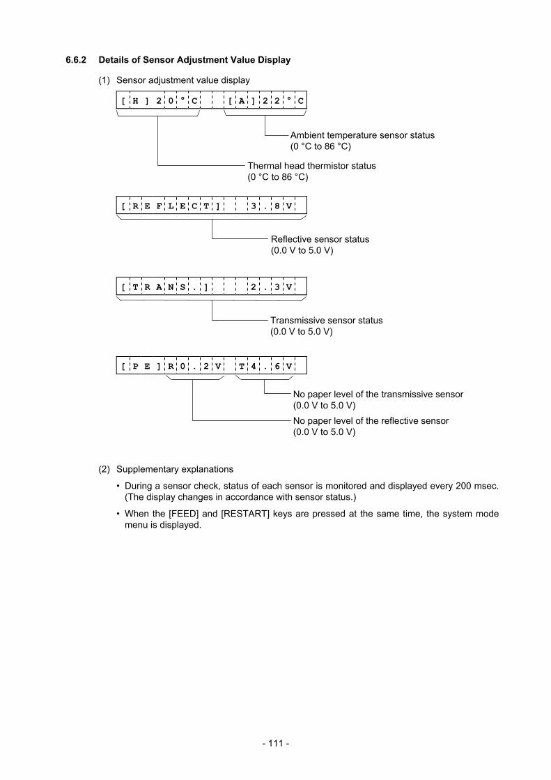
- 111 -
6.6.2 Details of Sensor Adjustment Value Display
(1) Sensor adjustment value display
[ H ] 2 0 ° C [ A ] 2 2 ° C
[ R E F L E C T ] 3 . 8 V
[ T R A N S . ] 2 . 3 V
[ P E ] R 0 . 2 V T 4 . 6 V
(2) Supplementary explanations
• During a sensor check, status of each sensor is monitored and displayed every 200 msec. (The display changes in accordance with sensor status.)
• When the [FEED] and [RESTART] keys are pressed at the same time, the system mode menu is displayed.
Ambient temperature sensor status (0 °C to 86 °C)
Thermal head thermistor status (0 °C to 86 °C)
No paper level of the reflective sensor (0.0 V to 5.0 V)
No paper level of the transmissive sensor (0.0 V to 5.0 V)
Reflective sensor status (0.0 V to 5.0 V)
Transmissive sensor status (0.0 V to 5.0 V)
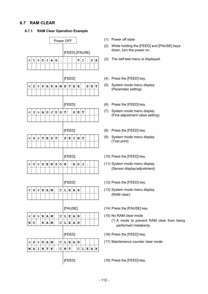
- 112 -
6.7 RAM CLEAR
6.7.1 RAM Clear Operation Example
Power OFF (1) Power off state
[FEED] [PAUSE]
(2) While holding the [FEED] and [PAUSE] keys down, turn the power on.
< 1 > D I A G . V 1 . 2 A
(3) The self-test menu is displayed.
[FEED] (4) Press the [FEED] key.
< 2 > P A R A M E T E R S E T
(5) System mode menu display (Parameter setting)
[FEED] (6) Press the [FEED] key.
< 3 > A D J U S T S E T
(7) System mode menu display (Fine adjustment value setting)
[FEED] (8) Press the [FEED] key.
< 4 > T E S T P R I N T
(9) System mode menu display (Test print)
[FEED] (10) Press the [FEED] key.
< 5 > S E N S O R A D J .
(11) System mode menu display (Sensor display/adjustment)
[FEED] (12) Press the [FEED] key.
< 6 > R A M C L E A R
(13) System mode menu display (RAM clear)
[PAUSE] (14) Press the [PAUSE] key.
< 6 > R A M C L E A R
N O R A M C L E A R
(15) No RAM clear mode (*) A mode to prevent RAM clear from being
performed mistakenly
[FEED] (16) Press the [FEED] key.
< 6 > R A M C L E A R
M A I N T E . C N T C L E A R
(17) Maintenance counter clear mode
[FEED] (18) Press the [FEED] key.
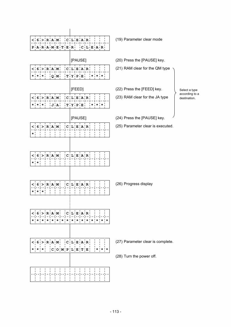
- 113 -
< 6 > R A M C L E A R
P A R A M E T E R C L E A R
(19) Parameter clear mode
[PAUSE] (20) Press the [PAUSE] key.
< 6 > R A M C L E A R
* * * Q M T Y P E * * *
(21) RAM clear for the QM type
[FEED] (22) Press the [FEED] key.
< 6 > R A M C L E A R
* * * J A T Y P E * * *
(23) RAM clear for the JA type
[PAUSE] (24) Press the [PAUSE] key.
< 6 > R A M C L E A R
*
(25) Parameter clear is executed.
< 6 > R A M C L E A R
* *
< 6 > R A M C L E A R
* * *
(26) Progress display
< 6 > R A M C L E A R
* * * * * * * * * * * * * * * *
< 6 > R A M C L E A R
* * * C O M P L E T E * * *
(27) Parameter clear is complete.
(28) Turn the power off.
Select a type according to a destination.
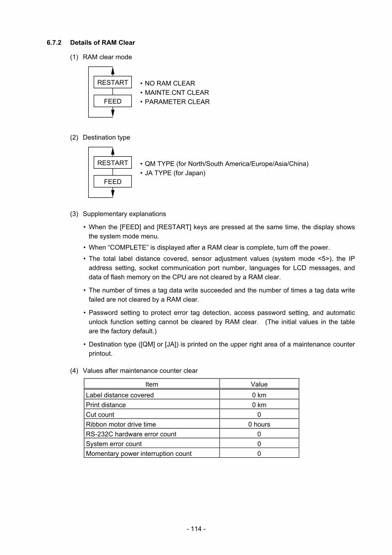
- 114 -
6.7.2 Details of RAM Clear
(1) RAM clear mode
• NO RAM CLEAR • MAINTE.CNT CLEAR • PARAMETER CLEAR
(2) Destination type
• QM TYPE (for North/South America/Europe/Asia/China) • JA TYPE (for Japan)
(3) Supplementary explanations
• When the [FEED] and [RESTART] keys are pressed at the same time, the display shows the system mode menu.
• When “COMPLETE” is displayed after a RAM clear is complete, turn off the power.
• The total label distance covered, sensor adjustment values (system mode <5>), the IP address setting, socket communication port number, languages for LCD messages, and data of flash memory on the CPU are not cleared by a RAM clear.
• The number of times a tag data write succeeded and the number of times a tag data write failed are not cleared by a RAM clear.
• Password setting to protect error tag detection, access password setting, and automatic unlock function setting cannot be cleared by RAM clear. (The initial values in the table are the factory default.)
• Destination type ([QM] or [JA]) is printed on the upper right area of a maintenance counter printout.
(4) Values after maintenance counter clear
Item Value Label distance covered 0 km Print distance 0 km Cut count 0 Ribbon motor drive time 0 hours RS-232C hardware error count 0 System error count 0 Momentary power interruption count 0
FEED
RESTART
FEED
RESTART
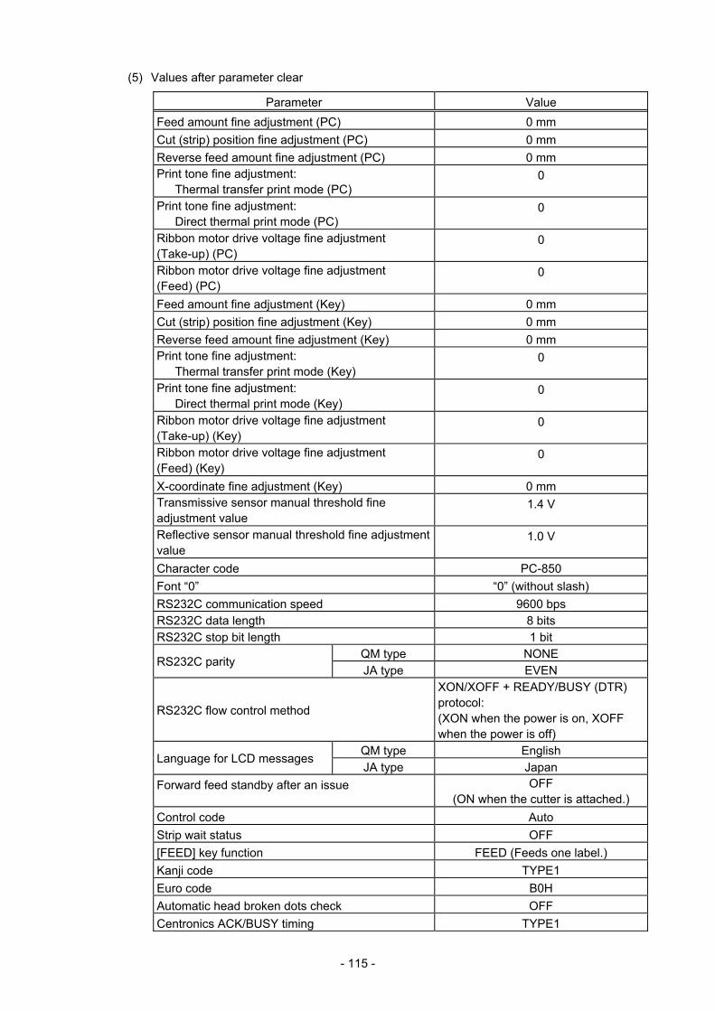
- 115 -
(5) Values after parameter clear
Parameter Value Feed amount fine adjustment (PC) 0 mm Cut (strip) position fine adjustment (PC) 0 mm Reverse feed amount fine adjustment (PC) 0 mm Print tone fine adjustment: Thermal transfer print mode (PC)
0
Print tone fine adjustment: Direct thermal print mode (PC)
0
Ribbon motor drive voltage fine adjustment (Take-up) (PC)
0
Ribbon motor drive voltage fine adjustment (Feed) (PC)
0
Feed amount fine adjustment (Key) 0 mm Cut (strip) position fine adjustment (Key) 0 mm Reverse feed amount fine adjustment (Key) 0 mm Print tone fine adjustment: Thermal transfer print mode (Key)
0
Print tone fine adjustment: Direct thermal print mode (Key)
0
Ribbon motor drive voltage fine adjustment (Take-up) (Key)
0
Ribbon motor drive voltage fine adjustment (Feed) (Key)
0
X-coordinate fine adjustment (Key) 0 mm Transmissive sensor manual threshold fine adjustment value
1.4 V
Reflective sensor manual threshold fine adjustment value
1.0 V
Character code PC-850 Font “0” “0” (without slash) RS232C communication speed 9600 bps RS232C data length 8 bits RS232C stop bit length 1 bit
QM type NONE RS232C parity JA type EVEN
RS232C flow control method
XON/XOFF + READY/BUSY (DTR) protocol: (XON when the power is on, XOFF when the power is off)
QM type English Language for LCD messages JA type Japan
Forward feed standby after an issue OFF (ON when the cutter is attached.)
Control code Auto Strip wait status OFF [FEED] key function FEED (Feeds one label.) Kanji code TYPE1 Euro code B0H Automatic head broken dots check OFF Centronics ACK/BUSY timing TYPE1

- 116 -
Parameter Value
Web printer function OFF Reset process when the nInit signal is ON OFF Ribbon near end detection OFF Expansion I/O operation mode Normal Plug-and-play operation mode OFF Label end/ribbon error process The printer stops an issue operation.Pre-strip process OFF Reverse feed speed 3 ips MaxiCode specification TYPE1 Keyboard I/F OFF Automatic calibration OFF LAN enable/disable Enable Status response ON Label pitch 76.2 mm Effective print length 74.2 mm
203 dpi 104.0 mm Effective print width 300 dpi 105.7 mm Print method Thermal transfer print mode Sensor type Transmissive sensor Feed speed 4”/sec. Issue mode Batch PC-save automatic call ON BASIC interpreter setting OFF BASIC interpreter trace setting OFF DHCP setting OFF RFID module type selection NONE RFID tag type selection NONE RFID module’s destination code setting (user-inaccessible setting) *Supported from C2.0C
Depending on the module setting (Supported from C2.0C)
RFID error tag detection OFF Password setting to protect error tag detection Disabled: 0000 Access password setting 00000000 Automatic unlock function setting Disabled Max. number of issue retires 3 Max. number of read retires 5 Read retry time-out 4.0 seconds Max. number of write retries 5 Write retry time-out 2.0 seconds RFID adjustment for retry OFF: +00 mm Radio output power level 251 AGC threshold 0 RFID channel (Not available to the B-SA704-RFID-U2-R)
AUTO
Q value 2 AGC threshold for data write 11 AGC threshold lower limit for retry 11 Hibiki tag multi-word write 0: OFF

- 117 -
Parameter Value System mode password setting OFF Strip motor torque R0 Print head applied current table setting TYPE1 High speed cut issue TYPE1 Multiple-label set issue OFF Z-Mode (C1.9A or later) OFF
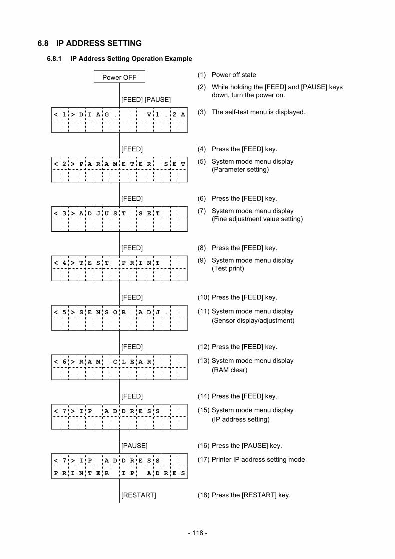
- 118 -
6.8 IP ADDRESS SETTING
6.8.1 IP Address Setting Operation Example
Power OFF (1) Power off state
[FEED] [PAUSE]
(2) While holding the [FEED] and [PAUSE] keys down, turn the power on.
< 1 > D I A G . V 1 . 2 A
(3) The self-test menu is displayed.
[FEED] (4) Press the [FEED] key.
< 2 > P A R A M E T E R S E T
(5) System mode menu display (Parameter setting)
[FEED] (6) Press the [FEED] key.
< 3 > A D J U S T S E T
(7) System mode menu display (Fine adjustment value setting)
[FEED] (8) Press the [FEED] key.
< 4 > T E S T P R I N T
(9) System mode menu display (Test print)
[FEED] (10) Press the [FEED] key.
< 5 > S E N S O R A D J .
(11) System mode menu display (Sensor display/adjustment)
[FEED] (12) Press the [FEED] key.
< 6 > R A M C L E A R
(13) System mode menu display (RAM clear)
[FEED] (14) Press the [FEED] key.
< 7 > I P A D D R E S S
(15) System mode menu display (IP address setting)
[PAUSE] (16) Press the [PAUSE] key.
< 7 > I P A D D R E S S
P R I N T E R I P A D R E S
(17) Printer IP address setting mode
[RESTART] (18) Press the [RESTART] key.
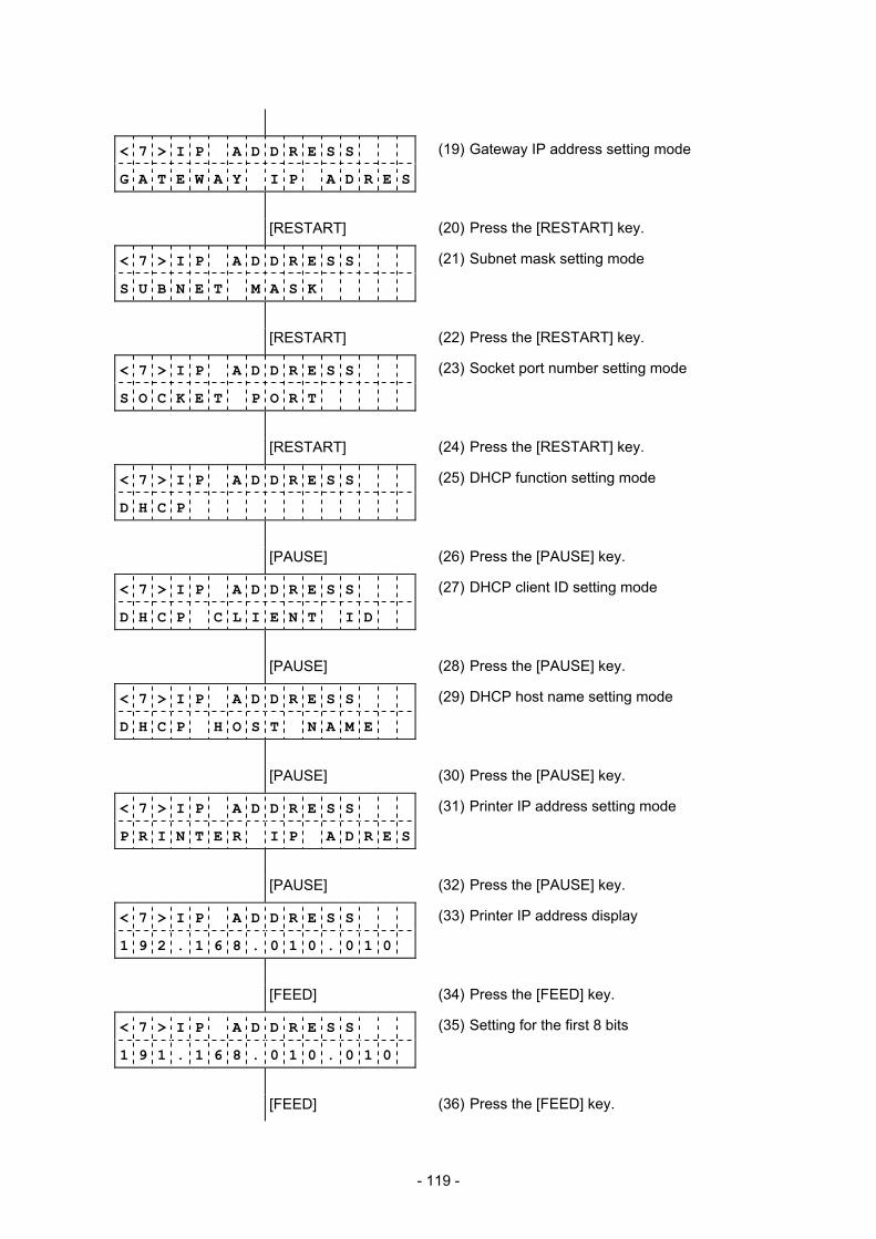
- 119 -
< 7 > I P A D D R E S S
G A T E W A Y I P A D R E S
(19) Gateway IP address setting mode
[RESTART] (20) Press the [RESTART] key.
< 7 > I P A D D R E S S
S U B N E T M A S K
(21) Subnet mask setting mode
[RESTART] (22) Press the [RESTART] key.
< 7 > I P A D D R E S S
S O C K E T P O R T
(23) Socket port number setting mode
[RESTART] (24) Press the [RESTART] key.
< 7 > I P A D D R E S S
D H C P
(25) DHCP function setting mode
[PAUSE] (26) Press the [PAUSE] key.
< 7 > I P A D D R E S S
D H C P C L I E N T I D
(27) DHCP client ID setting mode
[PAUSE] (28) Press the [PAUSE] key.
< 7 > I P A D D R E S S
D H C P H O S T N A M E
(29) DHCP host name setting mode
[PAUSE] (30) Press the [PAUSE] key.
< 7 > I P A D D R E S S
P R I N T E R I P A D R E S
(31) Printer IP address setting mode
[PAUSE] (32) Press the [PAUSE] key.
< 7 > I P A D D R E S S
1 9 2 . 1 6 8 . 0 1 0 . 0 1 0
(33) Printer IP address display
[FEED] (34) Press the [FEED] key.
< 7 > I P A D D R E S S
1 9 1 . 1 6 8 . 0 1 0 . 0 1 0
(35) Setting for the first 8 bits
[FEED] (36) Press the [FEED] key.
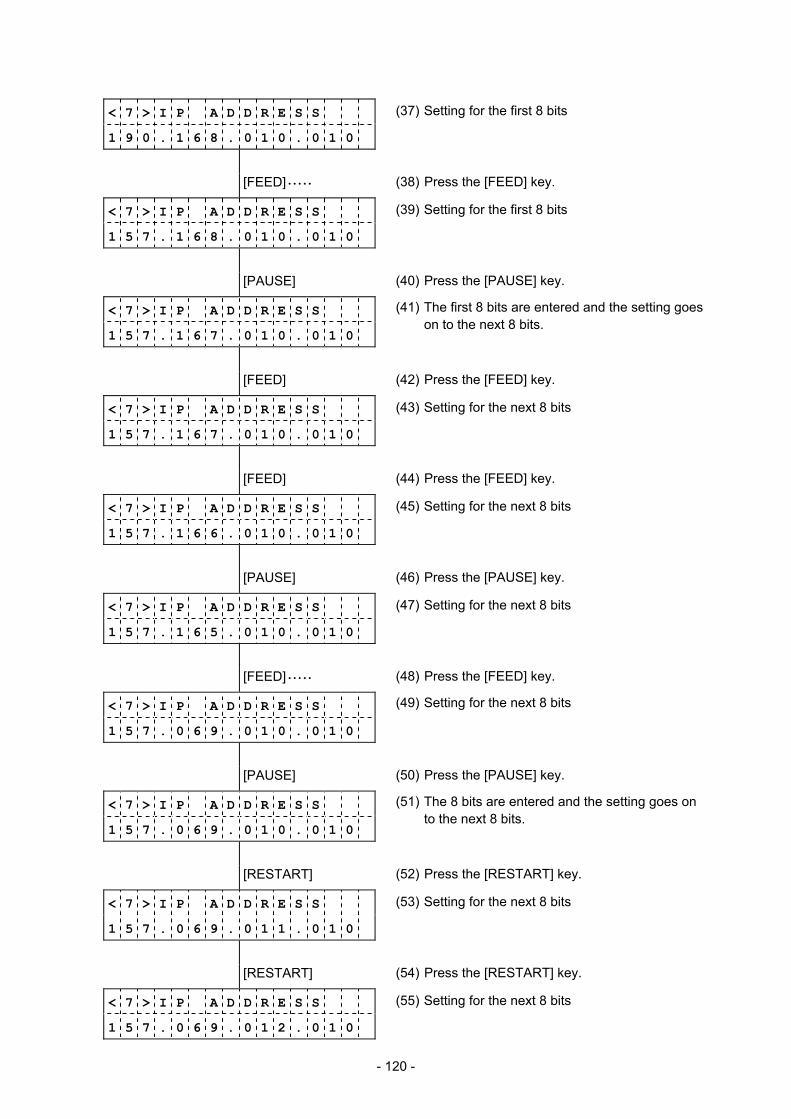
- 120 -
< 7 > I P A D D R E S S
1 9 0 . 1 6 8 . 0 1 0 . 0 1 0
(37) Setting for the first 8 bits
[FEED] • • • • • (38) Press the [FEED] key.
< 7 > I P A D D R E S S
1 5 7 . 1 6 8 . 0 1 0 . 0 1 0
(39) Setting for the first 8 bits
[PAUSE] (40) Press the [PAUSE] key.
< 7 > I P A D D R E S S
1 5 7 . 1 6 7 . 0 1 0 . 0 1 0
(41) The first 8 bits are entered and the setting goes on to the next 8 bits.
[FEED] (42) Press the [FEED] key.
< 7 > I P A D D R E S S
1 5 7 . 1 6 7 . 0 1 0 . 0 1 0
(43) Setting for the next 8 bits
[FEED] (44) Press the [FEED] key.
< 7 > I P A D D R E S S
1 5 7 . 1 6 6 . 0 1 0 . 0 1 0
(45) Setting for the next 8 bits
[PAUSE] (46) Press the [PAUSE] key.
< 7 > I P A D D R E S S
1 5 7 . 1 6 5 . 0 1 0 . 0 1 0
(47) Setting for the next 8 bits
[FEED] • • • • • (48) Press the [FEED] key.
< 7 > I P A D D R E S S
1 5 7 . 0 6 9 . 0 1 0 . 0 1 0
(49) Setting for the next 8 bits
[PAUSE] (50) Press the [PAUSE] key.
< 7 > I P A D D R E S S
1 5 7 . 0 6 9 . 0 1 0 . 0 1 0
(51) The 8 bits are entered and the setting goes on to the next 8 bits.
[RESTART] (52) Press the [RESTART] key.
< 7 > I P A D D R E S S
1 5 7 . 0 6 9 . 0 1 1 . 0 1 0
(53) Setting for the next 8 bits
[RESTART] (54) Press the [RESTART] key.
< 7 > I P A D D R E S S
1 5 7 . 0 6 9 . 0 1 2 . 0 1 0
(55) Setting for the next 8 bits

- 121 -
[RESTART] (56) Press the [RESTART] key.
< 7 > I P A D D R E S S
1 5 7 . 0 6 9 . 0 1 3 . 0 1 0
(57) Setting for the next 8 bits
[RESTART] • • • • • (58) Press the [RESTART] key.
< 7 > I P A D D R E S S
1 5 7 . 0 6 9 . 0 4 6 . 0 1 0
(59) Setting for the next 8 bits
[PAUSE] (60) Press the [PAUSE] key.
< 7 > I P A D D R E S S
1 5 7 . 0 6 9 . 0 4 6 . 0 1 0
(61) The 8 bits are entered and the setting goes on to the next 8 bits.
[RESTART] (62) Press the [RESTART] key.
< 7 > I P A D D R E S S
1 5 7 . 0 6 9 . 0 4 6 . 0 1 1
(63) Setting for the next 8 bits
[RESTART] (64) Press the [RESTART] key.
< 7 > I P A D D R E S S
1 5 7 . 0 6 9 . 0 4 6 . 0 1 2
(65) Setting for the next 8 bits
[RESTART] (66) Press the [RESTART] key.
< 7 > I P A D D R E S S
1 5 7 . 0 6 9 . 0 4 6 . 0 1 3
(67) Setting for the next 8 bits
[RESTART] • • • • • (68) Press the [RESTART] key.
< 7 > I P A D D R E S S
1 5 7 . 0 6 9 . 0 4 6 . 1 2 4
(69) Setting for the next 8 bits
[PAUSE] (70) Press the [PAUSE] key.
< 7 > I P A D D R E S S
G A T E W A Y I P A D R E S
(71) Gateway IP address setting mode
[PAUSE] (72) Press the [PAUSE] key.
< 7 > I P A D D R E S S
0 0 0 . 0 0 0 . 0 0 0 . 0 0 0
(73) Gateway IP address display
(74) Gateway IP address setting
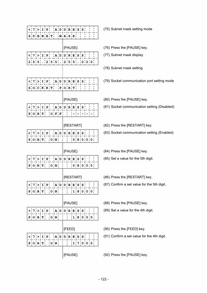
- 122 -
< 7 > I P A D D R E S S
S U B N E T M A S K
(75) Subnet mask setting mode
[PAUSE] (76) Press the [PAUSE] key.
< 7 > I P A D D R E S S
2 5 5 . 2 5 5 . 2 5 5 . 0 0 0
(77) Subnet mask display
(78) Subnet mask setting
< 7 > I P A D D R E S S
S O C K E T P O R T
(79) Socket communication port setting mode
[PAUSE] (80) Press the [PAUSE] key.
< 7 > I P A D D R E S S
P O R T O F F - - - - -
(81) Socket communication setting (Disabled)
[RESTART] (82) Press the [RESTART] key.
< 7 > I P A D D R E S S
P O R T O N 0 8 0 0 0
(83) Socket communication setting (Enabled)
[PAUSE] (84) Press the [PAUSE] key.
< 7 > I P A D D R E S S
P O R T O N 0 8 0 0 0
(85) Set a value for the 5th digit.
[RESTART] (86) Press the [RESTART] key.
< 7 > I P A D D R E S S
P O R T O N 1 8 0 0 0
(87) Confirm a set value for the 5th digit.
[PAUSE] (88) Press the [PAUSE] key.
< 7 > I P A D D R E S S
P O R T O N 1 8 0 0 0
(89) Set a value for the 4th digit.
[FEED] (90) Press the [FEED] key.
< 7 > I P A D D R E S S
P O R T O N 1 7 0 0 0
(91) Confirm a set value for the 4th digit.
[PAUSE] (92) Press the [PAUSE] key.
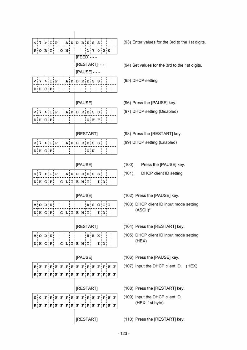
- 123 -
< 7 > I P A D D R E S S
P O R T O N 1 7 0 0 0
(93) Enter values for the 3rd to the 1st digits.
[FEED] • • • • •
[RESTART] • • • • • (94) Set values for the 3rd to the 1st digits.
[PAUSE] • • • • •
< 7 > I P A D D R E S S
D H C P
(95) DHCP setting
[PAUSE] (96) Press the [PAUSE] key.
< 7 > I P A D D R E S S
D H C P O F F
(97) DHCP setting (Disabled)
[RESTART] (98) Press the [RESTART] key.
< 7 > I P A D D R E S S
D H C P O N
(99) DHCP setting (Enabled)
[PAUSE] (100) Press the [PAUSE] key.
< 7 > I P A D D R E S S
D H C P C L I E N T I D
(101) DHCP client ID setting
[PAUSE] (102) Press the [PAUSE] key.
M O D E A S C I I
D H C P C L I E N T I D
(103) DHCP client ID input mode setting (ASCII)*
[RESTART] (104) Press the [RESTART] key.
M O D E H E X
D H C P C L I E N T I D
(105) DHCP client ID input mode setting (HEX)
[PAUSE] (106) Press the [PAUSE] key.
F F F F F F F F F F F F F F F F
F F F F F F F F F F F F F F F F
(107) Input the DHCP client ID. (HEX)
[RESTART] (108) Press the [RESTART] key.
0 0 F F F F F F F F F F F F F F
F F F F F F F F F F F F F F F F
(109) Input the DHCP client ID. (HEX: 1st byte)
[RESTART] (110) Press the [RESTART] key.
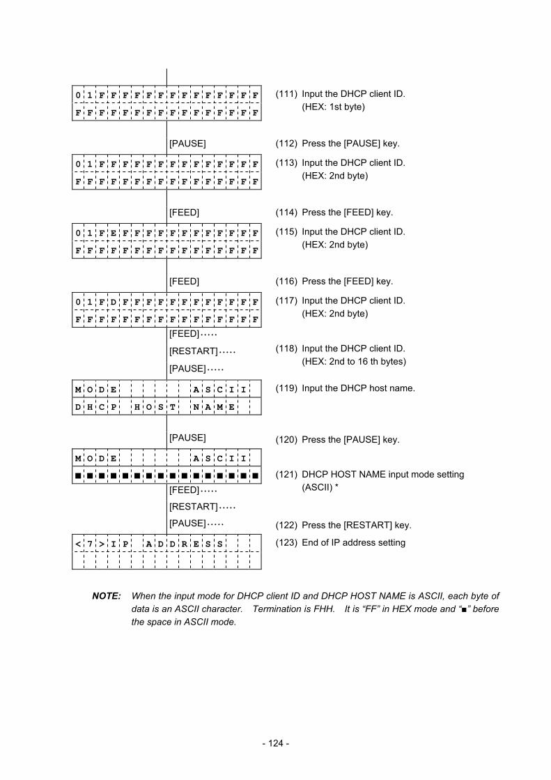
- 124 -
0 1 F F F F F F F F F F F F F F
F F F F F F F F F F F F F F F F
(111) Input the DHCP client ID. (HEX: 1st byte)
[PAUSE] (112) Press the [PAUSE] key.
0 1 F F F F F F F F F F F F F F
F F F F F F F F F F F F F F F F
(113) Input the DHCP client ID. (HEX: 2nd byte)
[FEED] (114) Press the [FEED] key.
0 1 F E F F F F F F F F F F F F
F F F F F F F F F F F F F F F F
(115) Input the DHCP client ID. (HEX: 2nd byte)
[FEED] (116) Press the [FEED] key.
0 1 F D F F F F F F F F F F F F
F F F F F F F F F F F F F F F F
(117) Input the DHCP client ID. (HEX: 2nd byte)
[FEED] • • • • •
[RESTART] • • • • •
[PAUSE] • • • • •
(118) Input the DHCP client ID.
(HEX: 2nd to 16 th bytes)
M O D E A S C I I (119) Input the DHCP host name.
D H C P H O S T N A M E
[PAUSE] (120) Press the [PAUSE] key.
M O D E A S C I I
■ ■ ■ ■ ■ ■ ■ ■ ■ ■ ■ ■ ■ ■ ■ ■
[FEED] • • • • •
(121) DHCP HOST NAME input mode setting (ASCII) *
[RESTART] • • • • •
[PAUSE] • • • • • (122) Press the [RESTART] key.
< 7 > I P A D D R E S S
(123) End of IP address setting
NOTE: When the input mode for DHCP client ID and DHCP HOST NAME is ASCII, each byte of data is an ASCII character. Termination is FHH. It is “FF” in HEX mode and “■” before the space in ASCII mode.

- 125 -
6.8.2 IP Address Setting Operation Flow
[PAUSE]
PRINTER IP ADRES
GATEWAY IP ADRES
SUBNET MASK
[RESTART] [FEED]
[RESTART] [FEED]
[FEED]
[RESTART]
000.000.000.000
[RESTART]
[FEED]
001.000.000.000
002.000.000.000
[RESTART]
255.000.000.000
254.000.000.000
[FEED]
[FEED]
[FEED]
[FEED]
[FEED]
[RESTART]
[RESTART]
[RESTART]
[RESTART]
000.000.000.000
[RESTART]
[FEED]
000.001.000.000
000.002.000.000
[RESTART]
000.255.000.000
000.254.000.000
[FEED]
[FEED]
[FEED]
[FEED]
[FEED]
[RESTART]
[RESTART]
[RESTART]
[RESTART]
[PAUSE]
SOCKET PORT
[FEED]
[RESTART]
DHCP
[FEED]
[RESTART]
DHCP CLIENT ID
[RESTART]
[FEED]
[RESTART] [FEED]
DHCP HOST NAME

- 126 -
6.9 BASIC SETTING
6.9.1 BASIC Setting Operation Example
Power OFF (1) Power off state
[FEED] [PAUSE]
(2) While holding the [FEED] and [PAUSE] keys down, turn the power on.
< 1 > D I A G . V 1 . 2 A
(3) The self-test menu is displayed.
[FEED] (4) Press the [FEED] key.
< 2 > P A R A M E T E R S E T
(5) System mode menu display (Parameter setting)
[FEED] (6) Press the [FEED] key.
< 3 > A D J U S T S E T
(7) System mode menu display (Fine adjustment value setting)
[FEED] (8) Press the [FEED] key.
< 4 > T E S T P R I N T
(9) System mode menu display (Test print)
[FEED] (10) Press the [FEED] key.
< 5 > S E N S O R A D J .
(11) System mode menu display (Sensor display/adjustment)
[FEED] (12) Press the [FEED] key.
< 6 > R A M C L E A R
(13) System mode menu display (RAM clear)
[FEED] (14) Press the [FEED] key.
< 7 > I P A D D R E S S
(15) System mode menu display (IP address setting)
[FEED] (16) Press the [FEED] key.
< 8 > B A S I C
(17) BASIC setting mode
[PAUSE] (18) Press the [PAUSE] key.
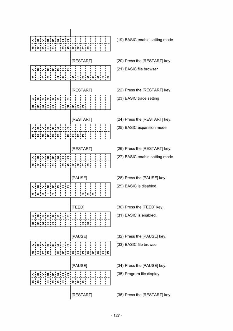
- 127 -
< 8 > B A S I C
B A S I C E N A B L E
(19) BASIC enable setting mode
[RESTART] (20) Press the [RESTART] key.
< 8 > B A S I C
F I L E M A I N T E N A N C E
(21) BASIC file browser
[RESTART] (22) Press the [RESTART] key.
< 8 > B A S I C
B A S I C T R A C E
(23) BASIC trace setting
[RESTART] (24) Press the [RESTART] key.
< 8 > B A S I C
E X P A N D M O D E
(25) BASIC expansion mode
[RESTART] (26) Press the [RESTART] key.
< 8 > B A S I C
B A S I C E N A B L E
(27) BASIC enable setting mode
[PAUSE] (28) Press the [PAUSE] key.
< 8 > B A S I C
B A S I C O F F
(29) BASIC is disabled.
[FEED] (30) Press the [FEED] key.
< 8 > B A S I C
B A S I C O N
(31) BASIC is enabled.
[PAUSE] (32) Press the [PAUSE] key.
< 8 > B A S I C
F I L E M A I N T E N A N C E
(33) BASIC file browser
[PAUSE] (34) Press the [PAUSE] key.
< 8 > B A S I C
0 0 T E S T . B A S
(35) Program file display
[RESTART] (36) Press the [RESTART] key.
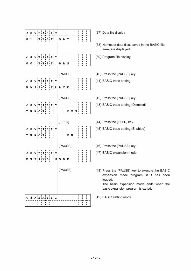
- 128 -
< 8 > B A S I C
0 1 T E S T . D A T
(37) Data file display
(38) Names of data files, saved in the BASIC file area, are displayed.
< 8 > B A S I C
0 0 T E S T . B A S
(39) Program file display
[PAUSE] (40) Press the [PAUSE] key.
< 8 > B A S I C
B A S I C T R A C E
(41) BASIC trace setting
[PAUSE] (42) Press the [PAUSE] key.
< 8 > B A S I C
T R A C E O F F
(43) BASIC trace setting (Disabled)
[FEED] (44) Press the [FEED] key.
< 8 > B A S I C
T R A C E O N
(45) BASIC trace setting (Enabled)
[PAUSE] (46) Press the [PAUSE] key.
< 8 > B A S I C
E X P A N D M O D E
(47) BASIC expansion mode
[PAUSE] (48) Press the [PAUSE] key to execute the BASIC expansion mode program, if it has been loaded. The basic expansion mode ends when the basic expansion program is exited.
< 8 > B A S I C
(49) BASIC setting mode
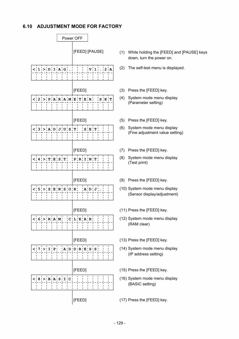
- 129 -
6.10 ADJUSTMENT MODE FOR FACTORY
Power OFF
[FEED] [PAUSE] (1) While holding the [FEED] and [PAUSE] keys down, turn the power on.
< 1 > D I A G . V 1 . 2 A
(2) The self-test menu is displayed.
[FEED] (3) Press the [FEED] key.
< 2 > P A R A M E T E R S E T
(4) System mode menu display (Parameter setting)
[FEED] (5) Press the [FEED] key.
< 3 > A D J U S T S E T
(6) System mode menu display (Fine adjustment value setting)
[FEED] (7) Press the [FEED] key.
< 4 > T E S T P R I N T
(8) System mode menu display (Test print)
[FEED] (9) Press the [FEED] key.
< 5 > S E N S O R A D J .
(10) System mode menu display (Sensor display/adjustment)
[FEED] (11) Press the [FEED] key.
< 6 > R A M C L E A R
(12) System mode menu display (RAM clear)
[FEED] (13) Press the [FEED] key.
< 7 > I P A D D R E S S
(14) System mode menu display (IP address setting)
[FEED] (15) Press the [FEED] key.
< 8 > B A S I C
(16) System mode menu display (BASIC setting)
[FEED] (17) Press the [FEED] key.
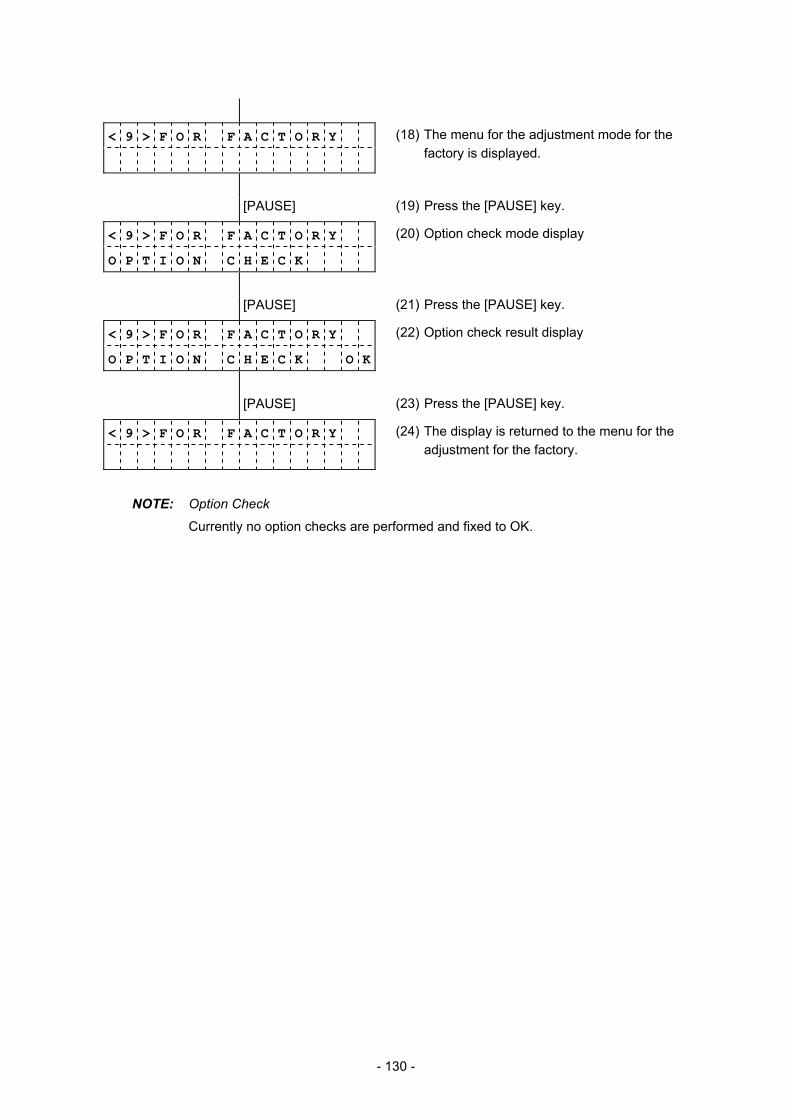
- 130 -
< 9 > F O R F A C T O R Y
(18) The menu for the adjustment mode for the factory is displayed.
[PAUSE] (19) Press the [PAUSE] key.
< 9 > F O R F A C T O R Y
O P T I O N C H E C K
(20) Option check mode display
[PAUSE] (21) Press the [PAUSE] key.
< 9 > F O R F A C T O R Y
O P T I O N C H E C K O K
(22) Option check result display
[PAUSE] (23) Press the [PAUSE] key.
< 9 > F O R F A C T O R Y
(24) The display is returned to the menu for the adjustment for the factory.
NOTE: Option Check
Currently no option checks are performed and fixed to OK.
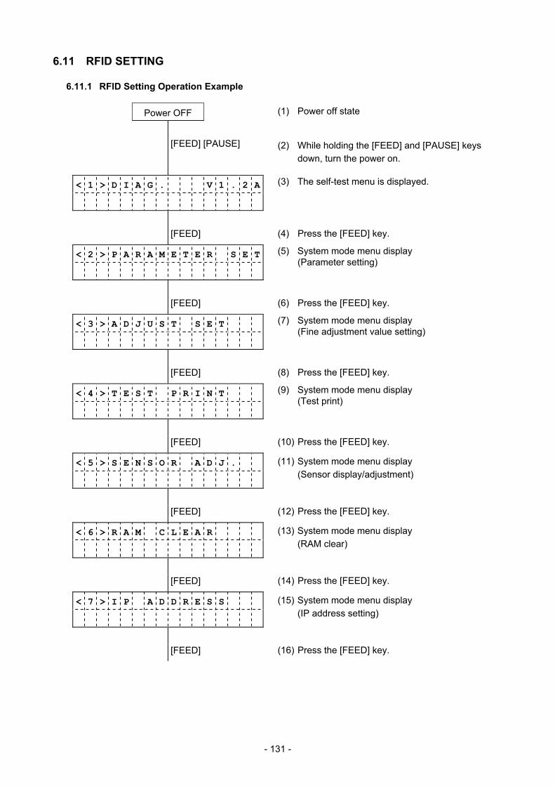
- 131 -
6.11 RFID SETTING
6.11.1 RFID Setting Operation Example
Power OFF (1) Power off state
[FEED] [PAUSE] (2) While holding the [FEED] and [PAUSE] keys down, turn the power on.
< 1 > D I A G . V 1 . 2 A
(3) The self-test menu is displayed.
[FEED] (4) Press the [FEED] key.
< 2 > P A R A M E T E R S E T
(5) System mode menu display (Parameter setting)
[FEED] (6) Press the [FEED] key.
< 3 > A D J U S T S E T
(7) System mode menu display (Fine adjustment value setting)
[FEED] (8) Press the [FEED] key.
< 4 > T E S T P R I N T
(9) System mode menu display (Test print)
[FEED] (10) Press the [FEED] key.
< 5 > S E N S O R A D J .
(11) System mode menu display (Sensor display/adjustment)
[FEED] (12) Press the [FEED] key.
< 6 > R A M C L E A R
(13) System mode menu display (RAM clear)
[FEED] (14) Press the [FEED] key.
< 7 > I P A D D R E S S
(15) System mode menu display (IP address setting)
[FEED] (16) Press the [FEED] key.
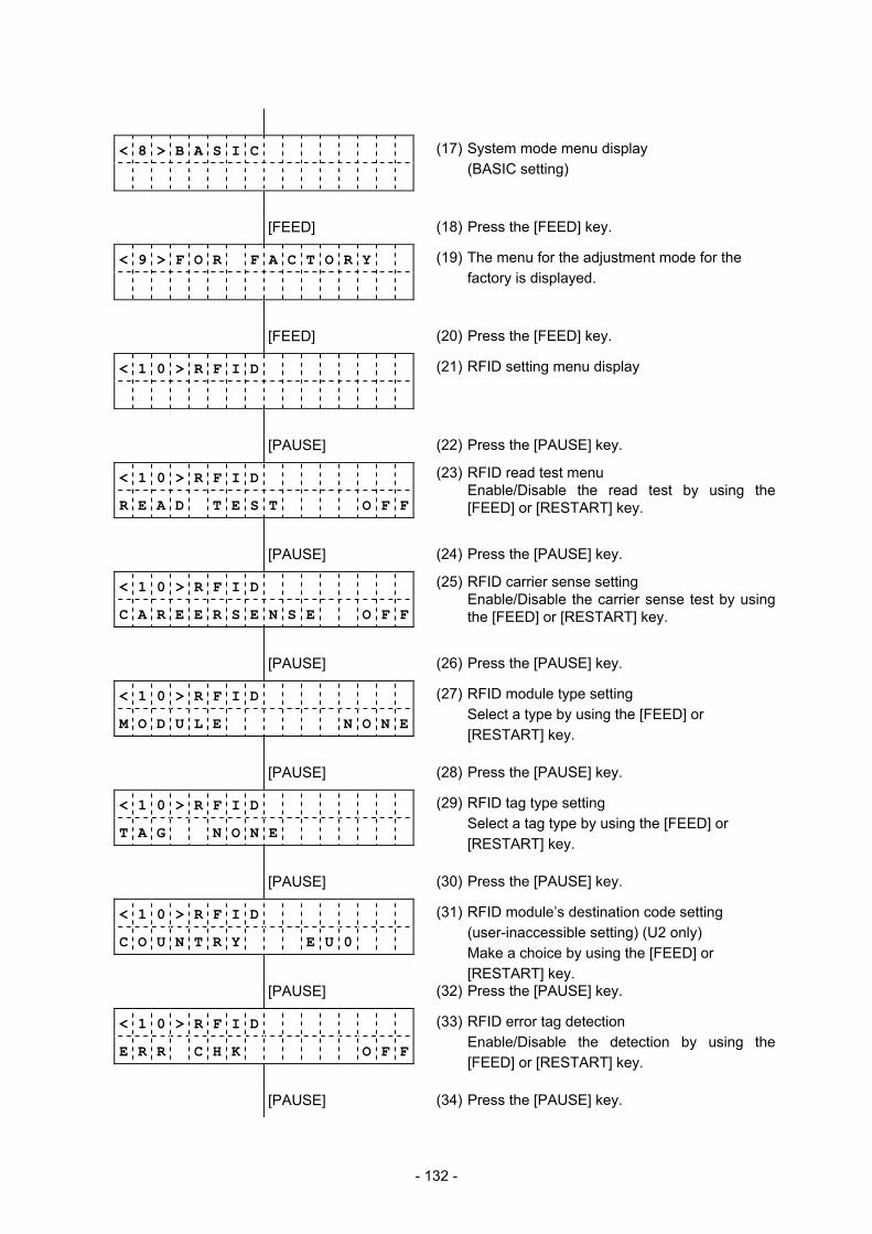
- 132 -
< 8 > B A S I C
(17) System mode menu display (BASIC setting)
[FEED] (18) Press the [FEED] key.
< 9 > F O R F A C T O R Y
(19) The menu for the adjustment mode for the factory is displayed.
[FEED] (20) Press the [FEED] key.
< 1 0 > R F I D
(21) RFID setting menu display
[PAUSE] (22) Press the [PAUSE] key.
< 1 0 > R F I D
R E A D T E S T O F F
(23) RFID read test menu Enable/Disable the read test by using the [FEED] or [RESTART] key.
[PAUSE] (24) Press the [PAUSE] key.
< 1 0 > R F I D
C A R E E R S E N S E O F F
(25) RFID carrier sense setting Enable/Disable the carrier sense test by using the [FEED] or [RESTART] key.
[PAUSE] (26) Press the [PAUSE] key.
< 1 0 > R F I D
M O D U L E N O N E
(27) RFID module type setting Select a type by using the [FEED] or [RESTART] key.
[PAUSE] (28) Press the [PAUSE] key.
< 1 0 > R F I D
T A G N O N E
(29) RFID tag type setting Select a tag type by using the [FEED] or [RESTART] key.
[PAUSE] (30) Press the [PAUSE] key.
< 1 0 > R F I D
C O U N T R Y E U 0
(31) RFID module’s destination code setting (user-inaccessible setting) (U2 only) Make a choice by using the [FEED] or [RESTART] key.
[PAUSE] (32) Press the [PAUSE] key.
< 1 0 > R F I D
E R R C H K O F F
(33) RFID error tag detection Enable/Disable the detection by using the [FEED] or [RESTART] key.
[PAUSE] (34) Press the [PAUSE] key.

- 133 -
< 1 0 > R F I D
I S S U E R E T R Y 3
(35) Maximum number of issue retries setting Set a value by using the [FEED] or [RESTART] key.
[PAUSE] (36) Press the [PAUSE] key.
< 1 0 > R F I D
R C Y C L E C N T 5
(37) Maximum number of read retries setting Set a value by using the [FEED] or [RESTART] key.
[PAUSE] (38) Press the [PAUSE] key.
< 1 0 > R F I D
R C Y C L E T I M 4 . 0
(39) Read retry time-out setting Set a value by using the [FEED] or [RESTART] key.
[PAUSE] (40) Press the [PAUSE] key.
< 1 0 > R F I D
W C Y C L E C N T 5
(41) Maximum number of write retries setting Set a value by using the [FEED] or [RESTART] key.
[PAUSE] (42) Press the [PAUSE] key.
< 1 0 > R F I D
W C Y C L E T I M 2 . 0
(43) Write retry time-out setting Set a value by using the [FEED] or [RESTART] key.
[PAUSE] (44) Press the [PAUSE] key.
< 1 0 > R F I D
A D J R E T R Y + 0 0
(45) RFID adjustment for retry Set a value by using the [FEED] or [RESTART] key.
[PAUSE] (46) Press the [PAUSE] key.
< 1 0 > R F I D
P O W E R L E V E L 1 8
(47) Radio output power level setting Set a value by using the [FEED] or [RESTART] key.
[PAUSE] (48) Press the [PAUSE] key.
< 1 0 > R F I D
A G C T H R E S H O L D 0
(49) AGC threshold setting Set a value by using the [FEED] or [RESTART] key.
[PAUSE] (50) Press the [PAUSE] key.
< 1 0 > R F I D
R F C H A N N E L A U T O
(51) RFID channel setting This menu is not available to the B-SA704-RFID-U2-EU-R.
[PAUSE] (52) Press the [PAUSE] key.

- 134 -
< 1 0 > R F I D
Q V A L U E 2
(53) Q value setting Set a value by using the [FEED] or [RESTART] key.
[PAUSE] (54) Press the [PAUSE] key.
< 1 0 > R F I D
W T A G C 1 1
(55) AGC threshold for data write Set a value by using the [FEED] or [RESTART] key.
[PAUSE] (56) Press the [PAUSE] key.
< 1 0 > R F I D
W T M I N A G C 1 1
(57) AGC threshold lower limit for retry Set a value by using the [FEED] or [RESTART] key.
[PAUSE] (58) Press the [PAUSE] key.
< 1 0 > R F I D
M U L T W R I T E O F F
(59) Hibiki tag multi-word write Enable/disable the function by using the [FEED] or [RESTART] key.
[PAUSE] (60) Press the [PAUSE] key.
< 1 0 > R F I D
(61) RFID setting menu display
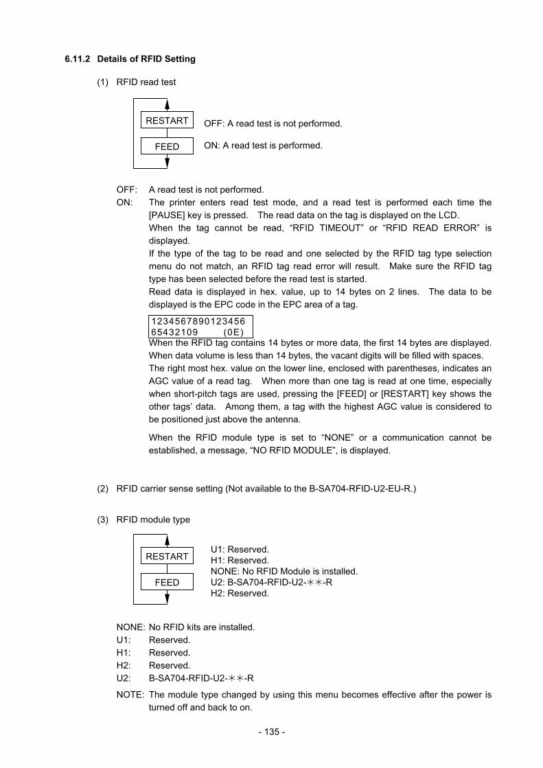
- 135 -
6.11.2 Details of RFID Setting
(1) RFID read test
OFF: A read test is not performed. ON: The printer enters read test mode, and a read test is performed each time the
[PAUSE] key is pressed. The read data on the tag is displayed on the LCD. When the tag cannot be read, “RFID TIMEOUT” or “RFID READ ERROR” is displayed. If the type of the tag to be read and one selected by the RFID tag type selection menu do not match, an RFID tag read error will result. Make sure the RFID tag type has been selected before the read test is started.
Read data is displayed in hex. value, up to 14 bytes on 2 lines. The data to be displayed is the EPC code in the EPC area of a tag. When the RFID tag contains 14 bytes or more data, the first 14 bytes are displayed. When data volume is less than 14 bytes, the vacant digits will be filled with spaces. The right most hex. value on the lower line, enclosed with parentheses, indicates an AGC value of a read tag. When more than one tag is read at one time, especially when short-pitch tags are used, pressing the [FEED] or [RESTART] key shows the other tags’ data. Among them, a tag with the highest AGC value is considered to be positioned just above the antenna.
When the RFID module type is set to “NONE” or a communication cannot be established, a message, “NO RFID MODULE”, is displayed.
(2) RFID carrier sense setting (Not available to the B-SA704-RFID-U2-EU-R.)
(3) RFID module type
NONE: No RFID kits are installed. U1: Reserved. H1: Reserved. H2: Reserved. U2: B-SA704-RFID-U2- -R
NOTE: The module type changed by using this menu becomes effective after the power is turned off and back to on.
FEED
RESTART
FEED
RESTART
OFF: A read test is not performed. ON: A read test is performed.
123456789012345665432109 (0E)
U1: Reserved. H1: Reserved. NONE: No RFID Module is installed. U2: B-SA704-RFID-U2- -R H2: Reserved.
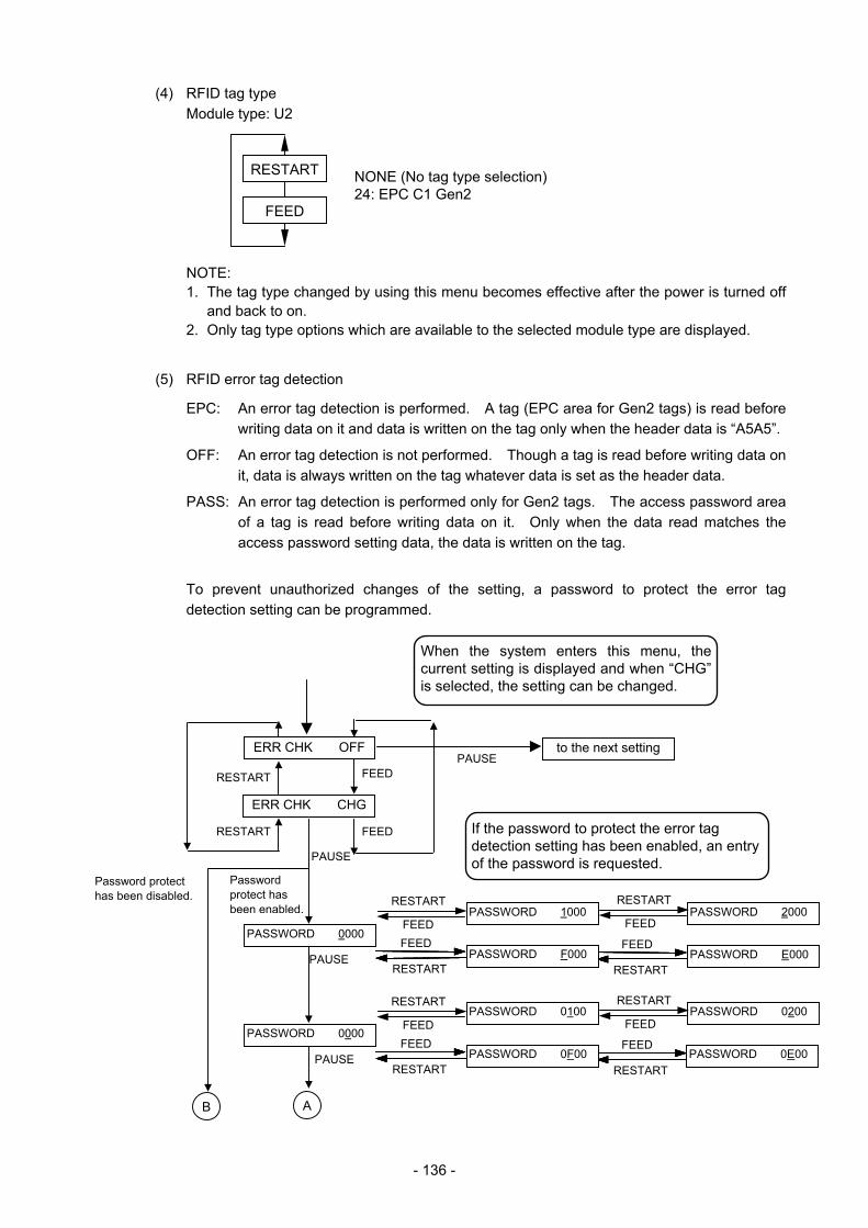
- 136 -
(4) RFID tag type Module type: U2
NOTE: 1. The tag type changed by using this menu becomes effective after the power is turned off
and back to on. 2. Only tag type options which are available to the selected module type are displayed.
(5) RFID error tag detection
EPC: An error tag detection is performed. A tag (EPC area for Gen2 tags) is read before writing data on it and data is written on the tag only when the header data is “A5A5”.
OFF: An error tag detection is not performed. Though a tag is read before writing data on it, data is always written on the tag whatever data is set as the header data.
PASS: An error tag detection is performed only for Gen2 tags. The access password area of a tag is read before writing data on it. Only when the data read matches the access password setting data, the data is written on the tag.
To prevent unauthorized changes of the setting, a password to protect the error tag
detection setting can be programmed.
FEED
RESTART NONE (No tag type selection) 24: EPC C1 Gen2
PASSWORD 0200
PASSWORD 0E00PAUSE
RESTART
FEEDFEED
RESTART
RESTART
FEED
FEED
RESTART
PASSWORD 0F00
PASSWORD 0100
ERR CHK OFF
ERR CHK CHG
PASSWORD 1000 PASSWORD 2000
PASSWORD E000
to the next setting PAUSE
RESTART
RESTART FEED
FEED
PAUSE
PAUSE
When the system enters this menu, the current setting is displayed and when “CHG”is selected, the setting can be changed.
If the password to protect the error tag detection setting has been enabled, an entry of the password is requested.
Password protect has been enabled.
Password protect has been disabled. RESTART
FEEDFEED
RESTART
RESTART
FEED
FEED
RESTART
PASSWORD F000
PASSWORD 0000
PASSWORD 0000
A B

- 137 -
PAUSE
A.PASS 00000000 A.PASS 20000000
A.PASS E0000000PAUSE
PAUSE
A.PASS 00000000 A.PASS 00000002
A.PASS 0000000E
PAUSE
Enter an 8-digit access password.
RESTART
FEEDFEED
RESTART
RESTART
FEED
FEED
RESTART
RESTART
FEEDFEED
RESTART
RESTART
FEED
FEED
RESTART
A.PASS 10000000
A.PASS F0000000
A.PASS 00000001
A.PASS 0000000F
ERR CHK OFF
ERR CHK EPC
ERR CHK PASS
to the next settingPAUSE
PAUSE
RESTART
RESTART
FEED
FEED
Password matches.
When selecting “PASS”, an entry of the access password is required.
Password does not match.
PASSWORD 0020
PASSWORD 00E0
PASSWORD 0002
PASSWORD 000E
PAUSE
PAUSE
RESTART
FEEDFEED
RESTART
RESTART
FEED
FEED
RESTART
PASSWORD 0010
PASSWORD 00F0
PASSWORD 0001
PASSWORD 000F
RESTART
FEEDFEED
RESTART
RESTART
FEED
FEED
RESTART
PASSWORD 0000
PASSWORD 0000
A
C
B
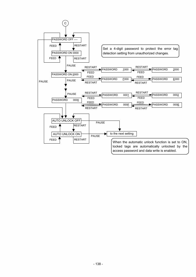
- 138 -
AUTO UNLOCK OFF
AUTO UNLOCK ON
RESTARTFEED
RESTARTFEED
to the next settingPAUSE
PAUSE
PASSWORD OFF ----
PASSWORD ON 0000
RESTARTFEED
RESTARTFEED
PAUSE
PASSWORD ON 0000
PASSWORD 2000
PASSWORD E000PAUSE
PASSWORD 0000
PASSWORD 0002
PASSWORD 000E
PAUSE
Set a 4-digit password to protect the error tag detection setting from unauthorized changes.
PAUSE
RESTART
FEEDFEED
RESTART
RESTART
FEED
FEED
RESTART
RESTART
FEEDFEED
RESTART
RESTART
FEED
FEED
RESTART
PASSWORD 1000
PASSWORD 0001
PASSWORD 000F
PASSWORD F000
When the automatic unlock function is set to ON, locked tags are automatically unlocked by the access password and data write is enabled.
C
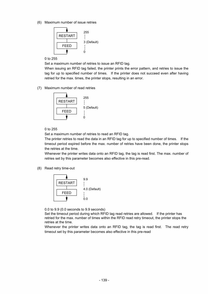
- 139 -
(6) Maximum number of issue retries
0 to 255 Set a maximum number of retries to issue an RFID tag.
When issuing an RFID tag failed, the printer prints the error pattern, and retries to issue the tag for up to specified number of times. If the printer does not succeed even after having retried for the max. times, the printer stops, resulting in an error.
(7) Maximum number of read retries
0 to 255 Set a maximum number of retries to read an RFID tag. The printer retries to read the data in an RFID tag for up to specified number of times. If the
timeout period expired before the max. number of retries have been done, the printer stops the retries at the time.
Whenever the printer writes data onto an RFID tag, the tag is read first. The max. number of retries set by this parameter becomes also effective in this pre-read.
(8) Read retry time-out
0.0 to 9.9 (0.0 seconds to 9.9 seconds)
Set the timeout period during which RFID tag read retries are allowed. If the printer has retried for the max. number of times within the RFID read retry timeout, the printer stops the retries at the time. Whenever the printer writes data onto an RFID tag, the tag is read first. The read retry timeout set by this parameter becomes also effective in this pre-read
FEED
RESTART 255 3 (Default) 0
FEED
RESTART 255 5 (Default) 0
FEED
RESTART 9.9 4.0 (Default) 0.0
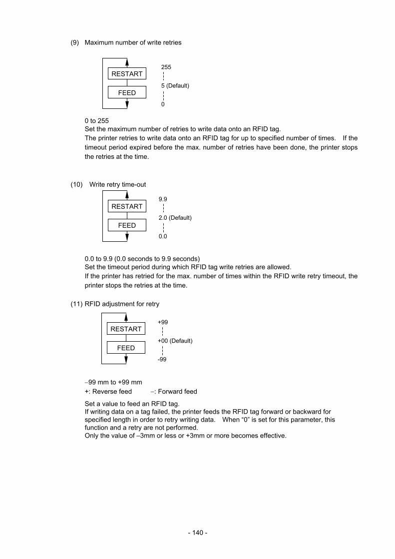
- 140 -
(9) Maximum number of write retries
0 to 255
Set the maximum number of retries to write data onto an RFID tag. The printer retries to write data onto an RFID tag for up to specified number of times. If the timeout period expired before the max. number of retries have been done, the printer stops the retries at the time.
(10) Write retry time-out
0.0 to 9.9 (0.0 seconds to 9.9 seconds)
Set the timeout period during which RFID tag write retries are allowed. If the printer has retried for the max. number of times within the RFID write retry timeout, the printer stops the retries at the time.
(11) RFID adjustment for retry
−99 mm to +99 mm +: Reverse feed −: Forward feed
Set a value to feed an RFID tag. If writing data on a tag failed, the printer feeds the RFID tag forward or backward for specified length in order to retry writing data. When “0” is set for this parameter, this function and a retry are not performed. Only the value of –3mm or less or +3mm or more becomes effective.
FEED
RESTART 255 5 (Default) 0
FEED
RESTART 9.9 2.0 (Default) 0.0
FEED
RESTART +99 +00 (Default) -99
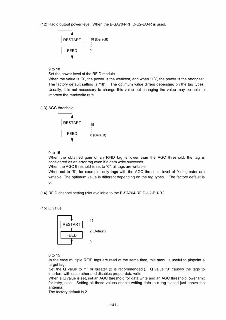
- 141 -
(12) Radio output power level: When the B-SA704-RFID-U2-EU-R is used.
9 to 18
Set the power level of the RFID module. When the value is “9”, the power is the weakest, and when “18”, the power is the strongest. The factory default setting is “18”. The optimum value differs depending on the tag types. Usually, it is not necessary to change this value but changing the value may be able to improve the read/write rate.
(13) AGC threshold
0 to 15
When the obtained gain of an RFID tag is lower than the AGC threshold, the tag is considered as an error tag even if a data write succeeds. When the AGC threshold is set to “0”, all tags are writable. When set to “8”, for example, only tags with the AGC threshold level of 9 or greater are writable. The optimum value is different depending on the tag types. The factory default is 0.
(14) RFID channel setting (Not available to the B-SA704-RFID-U2-EU-R.)
(15) Q value
0 to 15
In the case multiple RFID tags are read at the same time, this menu is useful to pinpoint a target tag. Set the Q value to “1” or greater (2 is recommended.). Q value “0” causes the tags to interfere with each other and disables proper data write. When a Q value is set, set an AGC threshold for data write and an AGC threshold lower limit for retry, also. Setting all these values enable writing data to a tag placed just above the antenna. The factory default is 2.
FEED
RESTART 15 0 (Default)
FEED
RESTART 15 2 (Default) 0
FEED
RESTART 18 (Default) 9
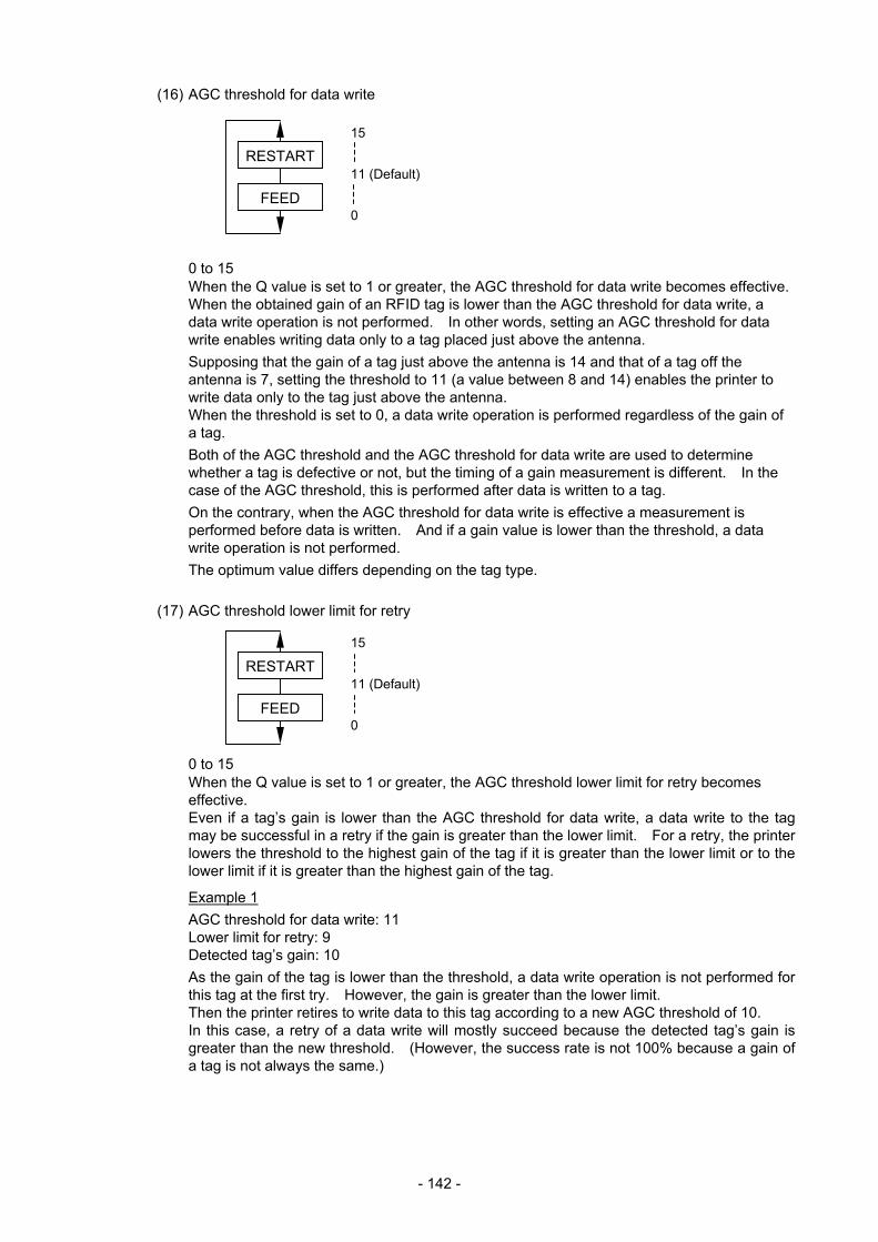
- 142 -
(16) AGC threshold for data write
0 to 15
When the Q value is set to 1 or greater, the AGC threshold for data write becomes effective. When the obtained gain of an RFID tag is lower than the AGC threshold for data write, a data write operation is not performed. In other words, setting an AGC threshold for data write enables writing data only to a tag placed just above the antenna. Supposing that the gain of a tag just above the antenna is 14 and that of a tag off the antenna is 7, setting the threshold to 11 (a value between 8 and 14) enables the printer to write data only to the tag just above the antenna. When the threshold is set to 0, a data write operation is performed regardless of the gain of a tag. Both of the AGC threshold and the AGC threshold for data write are used to determine whether a tag is defective or not, but the timing of a gain measurement is different. In the case of the AGC threshold, this is performed after data is written to a tag. On the contrary, when the AGC threshold for data write is effective a measurement is performed before data is written. And if a gain value is lower than the threshold, a data write operation is not performed. The optimum value differs depending on the tag type.
(17) AGC threshold lower limit for retry
0 to 15
When the Q value is set to 1 or greater, the AGC threshold lower limit for retry becomes effective. Even if a tag’s gain is lower than the AGC threshold for data write, a data write to the tag may be successful in a retry if the gain is greater than the lower limit. For a retry, the printer lowers the threshold to the highest gain of the tag if it is greater than the lower limit or to the lower limit if it is greater than the highest gain of the tag.
Example 1 AGC threshold for data write: 11 Lower limit for retry: 9 Detected tag’s gain: 10 As the gain of the tag is lower than the threshold, a data write operation is not performed for this tag at the first try. However, the gain is greater than the lower limit. Then the printer retires to write data to this tag according to a new AGC threshold of 10. In this case, a retry of a data write will mostly succeed because the detected tag’s gain is greater than the new threshold. (However, the success rate is not 100% because a gain of a tag is not always the same.)
FEED
RESTART 15 11 (Default) 0
FEED
RESTART 15 11 (Default) 0
- 143 -
Example 2 AGC threshold for data write: 11 Lower limit for retry: 9 Detected tag’s gain: 8 As the gain of the tag is lower than the threshold, a data write operation is not performed for this tag at the first try. Also, the gain is lower than the lower limit. Then the printer retries to write data to this tag according to a new AGC threshold of 9. In this case, a retry of data write will mostly fail because the detected tag’s gain is lower than the new threshold. (However, the error rate is not 100% because a gain of a tag is not always the same.)
When the same value is set to the AGC threshold for data write and the AGC threshold lower limit for retry, respectively, the threshold will not be changed for a retry. The optimum value differs depending on the tag type.
(18) Hibiki tag multi-word write
Gen2-compatible Hibiki tag (HITACHI) has a function which reduces the time to write data on the RFID chips. This is called “Multi-word write”. Use of this function enables a speed-up of the data write operation. However, this function is unique to the Hibiki tag, and not usable with the other Gen2-compatible chips. The factory default is set to OFF (disabled).
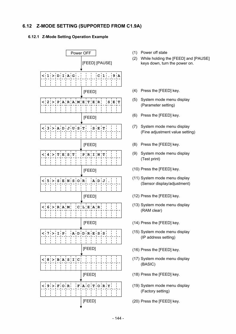
- 144 -
6.12 Z-MODE SETTING (SUPPORTED FROM C1.9A)
6.12.1 Z-Mode Setting Operation Example
< 1 > D I A G . C 1 . 9 A
< 2 > P A R A M E T E R S E T
< 3 > A D J U S T S E T
< 4 > T E S T P R I N T
< 5 > S E N S O R A D J .
< 6 > R A M C L E A R
< 7 > I P A D D R E S S
< 8 > B A S I C
< 9 > F O R F A C T O R Y
[FEED]
[FEED]
[FEED]
[FEED]
[FEED]
[FEED]
(2) While holding the [FEED] and [PAUSE] keys down, turn the power on.
(1) Power off state Power OFF
(17) System mode menu display (BASIC)
(19) System mode menu display (Factory setting)
(9) System mode menu display (Test print)
(11) System mode menu display (Sensor display/adjustment)
(13) System mode menu display (RAM clear)
(15) System mode menu display (IP address setting)
(7) System mode menu display (Fine adjustment value setting)
(4) Press the [FEED] key.
(5) System mode menu display (Parameter setting)
(6) Press the [FEED] key.
(8) Press the [FEED] key.
(10) Press the [FEED] key.
(12) Press the [FEED] key.
(14) Press the [FEED] key.
(16) Press the [FEED] key.
(18) Press the [FEED] key.
[FEED]
[FEED]
[FEED] (20) Press the [FEED] key.
[FEED] [PAUSE]
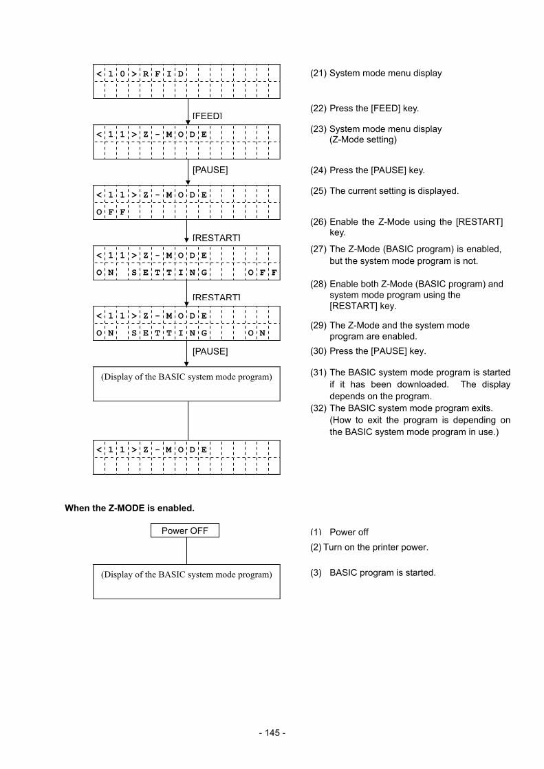
- 145 -
< 1 0 > R F I D
< 1 1 > Z - M O D E
< 1 1 > Z - M O D E
O F F
< 1 1 > Z - M O D E
O N S E T T I N G O F F
< 1 1 > Z - M O D E
O N S E T T I N G O N
(Display of the BASIC system mode program)
< 1 1 > Z - M O D E
When the Z-MODE is enabled.
(Display of the BASIC system mode program)
[FEED]
[RESTART]
[PAUSE]
[RESTART]
[PAUSE]
(2) Turn on the printer power.
(27) The Z-Mode (BASIC program) is enabled, but the system mode program is not.
(28) Enable both Z-Mode (BASIC program) and system mode program using the [RESTART] key.
(3) BASIC program is started.
(29) The Z-Mode and the system mode program are enabled.
(25) The current setting is displayed.
(22) Press the [FEED] key.
(23) System mode menu display (Z-Mode setting)
(21) System mode menu display
(24) Press the [PAUSE] key.
(26) Enable the Z-Mode using the [RESTART] key.
(30) Press the [PAUSE] key.
(31) The BASIC system mode program is startedif it has been downloaded. The display depends on the program.
(32) The BASIC system mode program exits. (How to exit the program is depending on the BASIC system mode program in use.)
(1) Power offPower OFF
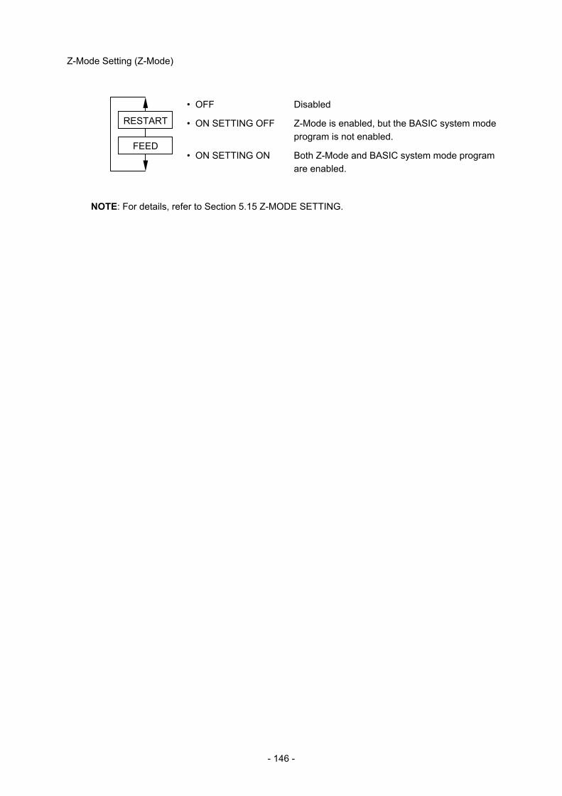
- 146 -
Z-Mode Setting (Z-Mode)
• OFF Disabled
• ON SETTING OFF Z-Mode is enabled, but the BASIC system mode program is not enabled.
• ON SETTING ON Both Z-Mode and BASIC system mode program are enabled.
NOTE: For details, refer to Section 5.15 Z-MODE SETTING.
FEED
RESTART
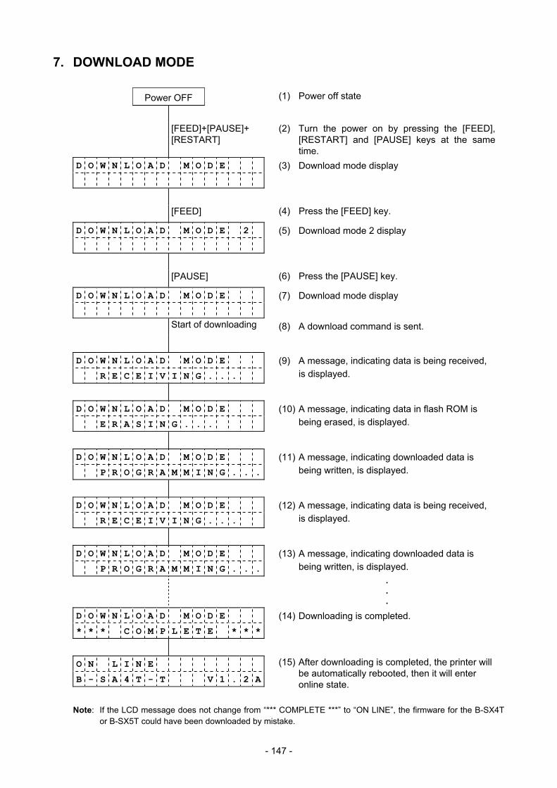
- 147 -
7. DOWNLOAD MODE
Power OFF (1) Power off state
[FEED]+[PAUSE]+ [RESTART]
(2) Turn the power on by pressing the [FEED], [RESTART] and [PAUSE] keys at the same time.
D O W N L O A D M O D E
(3) Download mode display
[FEED] (4) Press the [FEED] key.
D O W N L O A D M O D E 2
(5) Download mode 2 display
[PAUSE] (6) Press the [PAUSE] key.
D O W N L O A D M O D E
(7) Download mode display
Start of downloading (8) A download command is sent.
D O W N L O A D M O D E
R E C E I V I N G . . .
(9) A message, indicating data is being received, is displayed.
D O W N L O A D M O D E
E R A S I N G . . .
(10) A message, indicating data in flash ROM is being erased, is displayed.
D O W N L O A D M O D E
P R O G R A M M I N G . . .
(11) A message, indicating downloaded data is being written, is displayed.
D O W N L O A D M O D E
R E C E I V I N G . . .
(12) A message, indicating data is being received, is displayed.
D O W N L O A D M O D E
P R O G R A M M I N G . . .
(13) A message, indicating downloaded data is being written, is displayed.
•
•
•
D O W N L O A D M O D E
* * * C O M P L E T E * * *
(14) Downloading is completed.
O N L I N E
B - S A 4 T - T V 1 . 2 A
(15) After downloading is completed, the printer will be automatically rebooted, then it will enter online state.
Note: If the LCD message does not change from “*** COMPLETE ***” to “ON LINE”, the firmware for the B-SX4T or B-SX5T could have been downloaded by mistake.
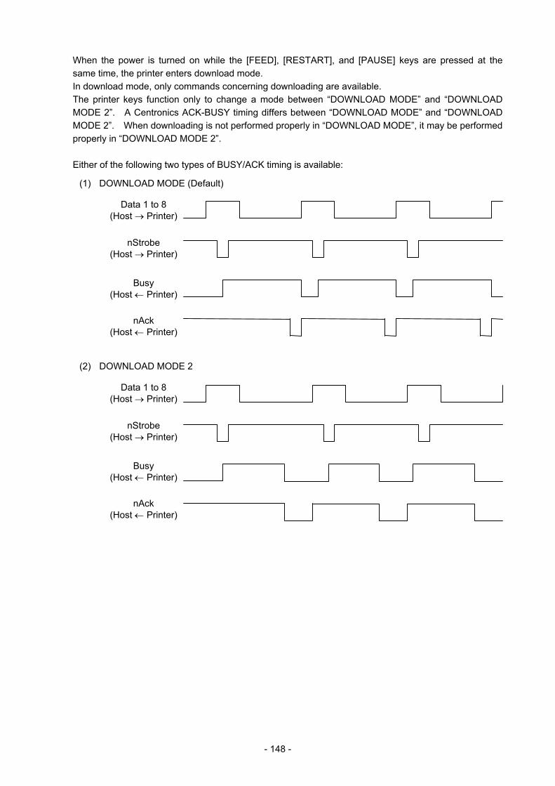
- 148 -
When the power is turned on while the [FEED], [RESTART], and [PAUSE] keys are pressed at the same time, the printer enters download mode. In download mode, only commands concerning downloading are available. The printer keys function only to change a mode between “DOWNLOAD MODE” and “DOWNLOAD MODE 2”. A Centronics ACK-BUSY timing differs between “DOWNLOAD MODE” and “DOWNLOAD MODE 2”. When downloading is not performed properly in “DOWNLOAD MODE”, it may be performed properly in “DOWNLOAD MODE 2”. Either of the following two types of BUSY/ACK timing is available:
(1) DOWNLOAD MODE (Default)
(2) DOWNLOAD MODE 2
nAck (Host ← Printer)
Busy (Host ← Printer)
nStrobe (Host → Printer)
Data 1 to 8 (Host → Printer)
nAck (Host ← Printer)
Busy (Host ← Printer)
nStrobe (Host → Printer)
Data 1 to 8 (Host → Printer)