torchmate 4x4 growth series - torchmate cnc plasma tables · torchmate growth series. vi. statement...
TRANSCRIPT

TMS-011-0404-02
with ACCUMOVE™2 Technology
Assembly and Operations Guide
Torchmate 4X4 Growth Series
2/1/2017Copyright 2012–2016 by Torchmate, Inc.

Torchmate Growth Seriesii
Published by:
Lincoln Electric Cutting Systems
Torchmate Distribution Center 1170 Trademark Drive, #101
Reno, NV 89521
www.torchmate.com
Copyright © 2012-2016 by Lincoln Electric Cutting Systems
All rights reserved.
Reproduction of this work, in whole or in part, without written permission of the publisher is prohibited.
The publisher does not assume and hereby disclaims any liability to any party for any loss or damage caused by any error or omission in this manual, whether such error results from negligence, accident, or any other cause.
Document TMS-011-0404-02

Assembly Guideiii
4X4 Growth SeriesCNC Cutting Table
pictured with optional water table and plasma torch

Torchmate Growth Seriesiv
Statement of Warranty. . . . . . . . . . . . . . . . . . . . . . . . . . . . . . . . . . . . . . . . . viWelcome to Torchmate . . . . . . . . . . . . . . . . . . . . . . . . . . . . . . . . . . . . . . . . . . . . viiiTorchmate Company History . . . . . . . . . . . . . . . . . . . . . . . . . . . . . . . . . . . . . . . . . ix
Technical Support . . . . . . . . . . . . . . . . . . . . . . . . . . . . . . . . . . . . . . . . . . . . .xSafety Information . . . . . . . . . . . . . . . . . . . . . . . . . . . . . . . . . . . . . . . . . . . . . . . . . . . . 1
Safety First. . . . . . . . . . . . . . . . . . . . . . . . . . . . . . . . . . . . . . . . . . . . . . . . . .2Receiving and Preparation . . . . . . . . . . . . . . . . . . . . . . . . . . . . . . . . . . . . . . . . . . . . . . 11
Preparations before assembly . . . . . . . . . . . . . . . . . . . . . . . . . . . . . . . . . . . . 12Receiving your shipment . . . . . . . . . . . . . . . . . . . . . . . . . . . . . . . . . . . . . . . . 14
Parts checklist . . . . . . . . . . . . . . . . . . . . . . . . . . . . . . . . . . . . . . . . . . . . . . . . . . . 15
Step-by-step setup . . . . . . . . . . . . . . . . . . . . . . . . . . . . . . . . . . . . . . . . . . . 22Assembling the cutting table. . . . . . . . . . . . . . . . . . . . . . . . . . . . . . . . . . . . . . . . . . . . . 25
Assembly overview . . . . . . . . . . . . . . . . . . . . . . . . . . . . . . . . . . . . . . . . . . . 26Step A1: Prepare table sides . . . . . . . . . . . . . . . . . . . . . . . . . . . . . . . . . . . . . . . . . . 28Step A2: Assemble table frame . . . . . . . . . . . . . . . . . . . . . . . . . . . . . . . . . . . . . . . . 29Step A3: Install the gantry . . . . . . . . . . . . . . . . . . . . . . . . . . . . . . . . . . . . . . . . . . .30Step A4: Check / adjust vertical bearings . . . . . . . . . . . . . . . . . . . . . . . . . . . . . . . . . . 31Step A5: Adjust the first cross-member. . . . . . . . . . . . . . . . . . . . . . . . . . . . . . . . . . . 32Step A6: Adjust the second cross-member. . . . . . . . . . . . . . . . . . . . . . . . . . . . . . . . . 33Step A7: Link the gantry to the drive screws . . . . . . . . . . . . . . . . . . . . . . . . . . . . . . . 34Step A8: Install first male cable carrier bracket. . . . . . . . . . . . . . . . . . . . . . . . . . . . . . 35Step A9: Install cable carrier support brackets . . . . . . . . . . . . . . . . . . . . . . . . . . . . . . 36Step A10: Install remaining cable carrier end brackets . . . . . . . . . . . . . . . . . . . . . . . . . 37Step A11: Install cable carrier links . . . . . . . . . . . . . . . . . . . . . . . . . . . . . . . . . . . . . . 38
Binding the Accumove™2 . . . . . . . . . . . . . . . . . . . . . . . . . . . . . . . . . . . . . . . . . . . . . . . 39
Overview of wiring. . . . . . . . . . . . . . . . . . . . . . . . . . . . . . . . . . . . . . . . . . . .40Step B1: Run crossover Ethernet cable . . . . . . . . . . . . . . . . . . . . . . . . . . . . . . . . . . . 41Step B2: Run motor cables . . . . . . . . . . . . . . . . . . . . . . . . . . . . . . . . . . . . . . . . . . . 42Step B3: Install the VMD software . . . . . . . . . . . . . . . . . . . . . . . . . . . . . . . . . . . . . . 43Step B4: Set the IP address . . . . . . . . . . . . . . . . . . . . . . . . . . . . . . . . . . . . . . . . . . .44Step B5: Start the Accumove 2 and log on to VMD . . . . . . . . . . . . . . . . . . . . . . . . . . . .45Step B6: Load configuration file for table . . . . . . . . . . . . . . . . . . . . . . . . . . . . . . . . .46Step B7: Setting and resetting the table's datum . . . . . . . . . . . . . . . . . . . . . . . . . . . . 47Step B8: Jog gantry to set side bearings . . . . . . . . . . . . . . . . . . . . . . . . . . . . . . . . . .48Step B9: Add underside bearings (optional) . . . . . . . . . . . . . . . . . . . . . . . . . . . . . . . .49Step B10: Test jog gantry at high speed. . . . . . . . . . . . . . . . . . . . . . . . . . . . . . . . . . .50Typical additional wiring steps . . . . . . . . . . . . . . . . . . . . . . . . . . . . . . . . . . . . . . . . 51
Mounting the water table (optional) . . . . . . . . . . . . . . . . . . . . . . . . . . . . . . . . . . . . . . . . 53
Contents

Assembly Guidev
Assemble the (optional) 4X4 water table. . . . . . . . . . . . . . . . . . . . . . . . . . . . . .54Step C1: Add a leveling foot to each leg . . . . . . . . . . . . . . . . . . . . . . . . . . . . . . . . . . . 57Step C2: Attach legs to panels for first corner. . . . . . . . . . . . . . . . . . . . . . . . . . . . . . .58Step C3: Extend the sides with legs and side panels. . . . . . . . . . . . . . . . . . . . . . . . . . .59Step C4: Complete the second and third corners . . . . . . . . . . . . . . . . . . . . . . . . . . . . .60Step C5: Complete the fourth corner . . . . . . . . . . . . . . . . . . . . . . . . . . . . . . . . . . . . 61Step C6: Insert cross members into frame . . . . . . . . . . . . . . . . . . . . . . . . . . . . . . . . . 62Step C7: Seal the water pans together . . . . . . . . . . . . . . . . . . . . . . . . . . . . . . . . . . . 63Step C8: Install the Drain Valve and pan . . . . . . . . . . . . . . . . . . . . . . . . . . . . . . . . . .64Step C9: Add the material support slats . . . . . . . . . . . . . . . . . . . . . . . . . . . . . . . . . .65Step C10: Secure cutting table to water table. . . . . . . . . . . . . . . . . . . . . . . . . . . . . . .66
Deploying the Plasma Cutter . . . . . . . . . . . . . . . . . . . . . . . . . . . . . . . . . . . . . . . . . . . . . 67
Cutting tools for Growth Series™ tables. . . . . . . . . . . . . . . . . . . . . . . . . . . . . . . .68Features of the Accumove2 AVHC . . . . . . . . . . . . . . . . . . . . . . . . . . . . . . . . . .69
Step D1: Attach the tool mounting bracket to the tool mounting pate. . . . . . . . . . . . . . . 71Step D2: Mount the AVHC lifter . . . . . . . . . . . . . . . . . . . . . . . . . . . . . . . . . . . . . . . . 73Step D3: Mount the Magnetic Breakaway Assembly . . . . . . . . . . . . . . . . . . . . . . . . . . 74Step D4: Prepare the Plasma Cutter . . . . . . . . . . . . . . . . . . . . . . . . . . . . . . . . . . . . . 75Step D5: Place the VFC unit. . . . . . . . . . . . . . . . . . . . . . . . . . . . . . . . . . . . . . . . . . . 77Step D6: Connect the VFC unit. . . . . . . . . . . . . . . . . . . . . . . . . . . . . . . . . . . . . . . . . 78Step D7: Wiring for Lincoln Electric plasma cutters . . . . . . . . . . . . . . . . . . . . . . . . . . .80Step D8: Wiring for non-Lincoln Electric plasma cutters . . . . . . . . . . . . . . . . . . . . . . . 82Step D9: Machine Grounding . . . . . . . . . . . . . . . . . . . . . . . . . . . . . . . . . . . . . . . . .84

Torchmate Growth Seriesvi
Statement of Warranty
Lincoln Electric Cutting Systems equipment is designed and built with quality in mind. However, your overall satisfaction with our products generally can be increased by proper installation ... and thoughtful operation on your part.
13. STATEMENT OF WARRANTY
A. Limited System Warranty
Except for Consumables or those parts customarily replaced due to wear and tear during the course of normal operation, Seller warrants its System to be free from defective material and workmanship for a period of twelve (12) months from the date of System shipment. Parts customarily replaced due to wear and tear include but are not limited to: lenses, fuses, lamps, scrapers, electrodes, shunts, emitters, and/or cutting nozzles. This warranty does not include routine mechanical, electrical, and electronic adjustment such as described in the instruction manuals furnished with the System. Such adjustments are the responsibility of Buyer.
This warranty specifically excludes all third party components or component parts not manufactured by Seller. Most third party manufactured components within the System(s) are warranted by the original manufacturers, and are not covered by Seller’s warranty. This warranty is void if the System has been subjected to improper installation, improper care, or abnormal operations, or if repairs or modifications have been undertaken without the express written approval of Seller, outside of a Seller’s Approved Service Facility (“ASF”), and/or without written authorization from the ASF prior to any such repair. This warranty also does not cover the repair and/or replacement of electrical or electronic parts damaged by improper voltage supplies, improper electrical connections to the System, or improper electrical grounding techniques. Buyer’s failure to follow all Seller recommended preventative maintenance schedules may also render the Seller’s warranty void.
Buyer shall contact Seller immediately upon the discovery of any defect or other basis of warranty coverage. Upon notification of non-conforming, inoperative, or defective System parts, or other claims of System warranty coverage, Seller reserves the right to inspect the System parts to determine warranty eligibility. The sole obligation of Seller hereunder is to replace or repair, at the Seller’s option, any part which the Seller, in its sole discretion, determines to be defective under normal use and service during the warranted period.
If Seller confirms the existence of a defect covered by Seller’s warranty, Seller shall create a Return Merchandise Authorization (“RMA”) approving the repair or replacement of the defective or inoperable System part/component and shall assist the Buyer with the coordination of its warranty service. An approved RMA must accompany any System part/component shipped to an ASF for warranty repair or replacement. Any such shipments to and from an ASF for warranty repair or replacement shall be at the sole expense and risk of the Buyer or Buyer’s End User. At Seller’s request, any defective System parts or components thereof shall be returned to Seller.
Warranty
Before returning any goods, please contact Lincoln Electric Cutting Systems Technical Support
Monday through Friday from 7 AM to 4 PM (07:00 to 16:00), Pacific Time Zone.
Toll Free: 1-866-571-1066International: 775-673-2200
Fax: 775-673-2206Email: [email protected]
Assembly Guidevii
Limited Warranty for Component Parts (“Component Parts Warranty”)
Component Parts manufactured by Seller, except for Consumables or those parts customarily replaced due to wear and tear during the course of normal operation, or Component Parts that are part of either the Torchmate 4400 or Torchmate 4800 systems, are warranted by Seller’s Component Part Warranty to be free from defective material and workmanship for a period of up to twelve (12) months from the date of System shipment to Buyer. Component Parts that are part of either Torchmate 4400 or Torchmate 4800 system are warranted by Seller’s Component Part Warranty to be free from defective material and workmanship for a period of up to twenty-four (24) months from the date of System shipment to Buyer. Buyer shall contact Seller immediately upon the discovery of any defective manufactured Component Part or other claims of warranty coverage. If the Seller confirms the existence of a defect covered by Seller’s Component Part Warranty, Seller shall create a Return Merchandise Authorization (RMA) approving the repair or replacement of the defective component(s) and/or Component Part(s) and shall assist the Buyer with the coordination of warranty service. An approved RMA must accompany the component(s) and/or Component Part(s) shipped to an ASF. Final determination of warranty coverage eligibility shall be made by the Seller. Component(s) and/or Component Part(s) shipped to and from an ASF for warranty repair or replacement shall be at the sole expense and risk of the Buyer or Buyer’s End User. Any Component Parts to be returned for full or partial refund must be in new, unused (except for bench testing), and saleable condition and approved by Seller in Seller’s sole discretion.
A return authorization number (RAN) must be obtained by the Buyer prior to any return. Shipments of returned items not marked with a valid RAN will be refused. Seller’s Component Parts Warranty in no way extends the System Warranty.
Almost all third-party original equipment manufacturer (“OEM”) Component Parts used in Seller’s System(s) are warranted by the OEM, and are therefore not covered by Seller’s Component Part Warranty. If OEM Component Parts are found to be defective or non-conforming and are covered by an OEM warranty, Seller shall assist Buyer in identifying any defects and shall work with local distributors to ensure that OEM Component Parts are repaired or replaced as required, subject to the terms and restrictions of the OEM’s warranty.
B. Limited Warranty for Consumables
All Consumables are warranted by a third-party OEM and are therefore not covered by Seller’s warranty. Requests for warranty eligibility for Consumables shall be evaluated on a case-by-case basis and shall be determined by Seller in its sole discretion. To request a determination for warranty eligibility and/or to request warranty service for Consumables, Buyer must contact the Seller directly. Warranty periods for Consumables are for up to one year, vary by product, and are subject to the terms of the OEM warranty. The warranty period starts from the date of shipment of the Goods to Buyer.
C. Warranty Limitations
Seller’s warranties do not apply to any Goods that have been subjected to misuse, mishandling, misapplication, neglect (including but not limited to improper maintenance), accident, improper installation, modification (including by not limited to use of unauthorized parts or attachments), or adjustment or repair performed by anyone other than Seller or one of Seller’s authorized agents. When returning Goods to Seller for warranty replacement or repair, packaging must be adequate, or else Seller’s warranty is null and void. Buyer will pay for the cost of shipping to and from Seller for all approved warranty repairs.
Warranty (contd)

Torchmate Growth Seriesviii
Warranty (contd) THE WARRANTIES SET FORTH HEREIN ARE THE ONLY WARRANTIES PROVIDED BY SELLER WITH RE-SPECT TO THE SYSTEM, COMPONENT PARTS, AND CONSUMABLES. SELLER WILL NOT ACCEPT RESPON-SIBILITY OR LIABILITY FOR REPAIRS MADE OUTSIDE OF AN AUTHORIZED SERVICE FACILITY (“ASF”). SELL-ER’S LIABILITY UNDER THIS WARRANTY SHALL NOT EXCEED THE COST OF REPAIRING OR REPLACING THE GOODS, OR REFUNDING THE BUYER OR END USER AN AMOUNT EQUAL TO THE TOTAL PURCHASE PRICE OF THE GOODS, WHICHEVER REMEDY SELLER CHOOSES IN ITS SOLE DISCRETION. SELLER WILL NOT BE LIABLE FOR ANY INCIDENTAL OR CONSEQUENTIAL DAMAGES CAUSED BY ANY DEFECT OR THE TIME INVOLVED TO CORRECT THE DEFECT. BUYER ASSUMES ALL RISK WHATSOEVER AS TO THE RESULT OF THE USE OF THE GOODS, WHETHER USED ALONE OR IN COMBINATION WITH OTHER PRODUCTS OR SUB-STANCES. SELLER MAKES NO OTHER WARRANTIES, EXPRESS OR IMPLIED INCLUDING, BUT NOT LIMITED TO, ANY IMPLIED WARRANTIES OF MERCHANTABILITY OR FITNESS FOR A PARTICULAR PURPOSE, WHICH ARE EXPRESSLY DISCLAIMED.
The exclusive remedies set forth herein shall not be deemed to have failed of their essential purpose so long as Seller is willing and able to repair or replace defective Goods as set forth herein. No affirmation of Seller, by words or action, other than as set forth in herein, shall constitute a warranty. Any claim by Buyer with reference to the Goods sold hereunder shall be deemed waived by the Buyer unless submitted in writ-ing to seller within the earlier of (i) thirty (30) days following the date Buyer discovered or by reasonable inspection should have discovered, any claimed breach of foregoing warranty, or (ii) 12 months following the date of shipment. Any cause of action for breach of the foregoing warranty must be brought within one year from the date the alleged breach was discovered or should have been discovered, whichever occurs first.

Assembly Guideix
To the newest member of our Torchmate Family:
Thank You! Thank you for putting your faith and trust in Torchmate. When you purchased your Torchmate CNC Cutting System, you purchased more than just a machine. You pur-chased a team. The Torchmate team was built with the goal in mind of helping you get the most value out of your automation investment.
For some, this Torchmate CNC Cutting System purchase is their first endeavor into the world of automation. Others may consider themselves seasoned automation experts. No matter which category you fall into, it is important that you realize that investing in a Torchmate is unlike any other machinery purchase you have made. We consider your success our success as well as your challenges our challenges.
The Torchmate product line is designed to be simple, reliable, and accurate. While there is no “Easy” button on your new system, we can promise that you will get out of it what you put in. Operating any machinery is a skill and does have a learning curve.
The first and perhaps most important item we want to give you today is the Torchmate Technical Support Hotline: (866) 571-1066. This number is toll free for those within the Unit-ed States. For those outside the United States, use the following telephone number (775) 673-2200. Our dedicated professional support staff is available Monday through Friday from 7 AM to 4 PM (07:00 to 16:00), Pacific Time to assist you in any way that they can. We pride ourselves on offering free unlimited telephone support for your machine and all we expect in return is communication, understanding and patience. We are here for you as long as you need us.
Please don’t be a stranger. If you have questions or problems, call us. No matter how trivial your issue may seem it is not trivial if it cuts into your productivity. Call, Call, Call! We are here for you! Thank you again for putting your trust in us. We will do our best to not let you down.
Sincerely,
The Torchmate Team LIncoln Electric Cutting Systems
Welcome to Torchmate
Call us for help
Welcome Letter

Torchmate Growth Seriesx
The year was 1979. After spending his childhood working with metal and hot rods, William (Bill) Kunz, Sr. began selling his first shape-cutting machine. He called it the “Torchmate.”
Bill had read about pantograph flame-cutting machines in an automotive magazine, so he set out to bring this technology to hobbyists and small shop owners like himself. His funda-mental idea? Find a way to lower the $1,400 cost (a big investment 30 years ago) down to just $400—thanks to the first Torchmate Pantograph Machine Kits.
Torchmate sold thousands of pantograph machines over the next 18 years, and the compa-ny’s objective has remained steadfast: cutting technology should not be limited only to the metalworking elite.
Not content to rest on his laurels, Bill launched Torchmate’s line of CNC (Computer Numeri-cally Controlled) Cutting Machines in the late 1990s. The pantograph evolved into an auto-mated, two-axis cutting table featuring a rugged yet precise plasma torch.
Following the same fundamental idea from the company’s founding, the Torchmate tables brought major cost reductions, allowing plasma cutting (which had been expensively out of reach for most shops) to be widely affordable. The cut quality, increased production, and precise replication were also highly appreciated capabilities of the new machines.
In early 2001 and with the help of Kunz’s son, Bill Jr., the company unveiled the Torchmate 2, which used an extruded aluminum gantry. It cut customer fabrication time from 40 hours down to just 16. Adding a third axis expanded functionality into the Routermate, which cuts wood, plastic, foam, and other materials using a router / drill, in 3-D.
Then came the Torchmate 3, with its strong aluminum-extrusion frame that assembles in less than a day—and a price point under $10,000.
The most recent new Torchmate products include the large Torchmate X table and, more recently, the revolutionary new Growth Series: the expandable Torchmate 2x2, 2x4, and 4x4 CNC Systems.
In 2011, the Kunz’ family vision was realized when Lincoln Electric, a stalwart welding machine company from Cleveland, Ohio, acquired Torchmate. To bring world-class metal cutting equipment to its customers world-wide, Torchmate will continue to create, sell, and support products in Reno, NV.
Torchmate Company History

Assembly Guidexi
Toll Free: 1-866-571-1066
International: 775-673-2200
Fax: 775-673-2206
Email: [email protected]
When building the table if a question or concern arises or a part is missing, please contact Torchmate technical support.
Technical support will also help you with operating the CNC system, and with troubleshooting problems.
Torchmate Technical Support is available Monday through Friday from 7 AM to 4 PM (07:00 to 16:00), Pacific Time Zone.
Call, Fax, or Email
Technical Support
Call us for Consumables, or visit our web store
www.TorchmateStore.com

Assembly Guide1
Safety Information
Torchmate Growth Series2
Lincoln Electric Cutting Systems equipment is designed and built with safety in mind. However, your overall safety can be increased by proper installation ... and thoughtful operation on your part.
Safety First
1. ELECTRIC SHOCK can kill.
1.1 The electrode and work (or ground) circuits are electrically “hot” when the power source is on. Do not touch these “hot” parts with your bare skin or wet clothing. Wear dry, hole-free gloves to insulate hands.
1.2 Disconnect the power source before performing any service or repairs. When the power source is operating, voltages in excess of 250 volts are produced. This creates the potential for serious electrical shock - possibly even fatal.
1.3 Insulate yourself from work and ground using dry insulation. Wear dry gloves and clothing. Take extra care when the work place is moist or damp.
1.4 Always be sure the work cable makes a good electrical connection with the metal being cut or gouged. The connection should be as close as possible to the area being cut or gouged.
1.5 Ground the work or metal to be cut or gouged to a good electrical (earth) ground.
1.6 Maintain the plasma torch, cable and work clamp in good, safe operating condition. Repair or replace all worn or damaged parts. Replace damaged insulation.
1.7 Never dip the torch in water for cooling or plasma cut or gouge in or under water.
1.8 When working above floor level, protect yourself from a fall should you get a shock.
1.9 Operate the pilot arc with caution. The pilot arc is capable of burning the operator, others or even piercing safety clothing.
1.10 Also see Items 4.3 and 6.
2. ARC RAYS can burn.
DO NOT INSTALL, OPERATE, OR REPAIR THIS EQUIPMENT WITHOUT READING THE SAFETY WARNINGS
CONTAINED THROUGHOUT THIS MANUAL
Think before you act— and be careful.
Electric shock
PROTECT YOURSELF AND OTHERS FROM POSSIBLE SERIOUS INJURY OR DEATH. KEEP CHILDREN AWAY.
IF YOU WEAR A PACEMAKER, CONSULT WITH YOUR DOCTOR BEFORE OPERATING.
Read and understand the following safety highlights. For additional safety information it is strongly recommended that you purchase a copy of “Safety in Welding & Cutting - ANSI Standard Z49.1” from the American Welding Society, P.O. Box 351040, Miami, Florida 33135 or CSA Standard W117.2.
BE SURE THAT ALL INSTALLATION, OPERATION, MAINTENANCE, AND REPAIR PROCEDURES ARE PER-FORMED ONLY BY QUALIFIED INDIVIDUALS.
WARNING

Assembly Guide3
2.1 Plasma Arc Rays can injure your eyes and burn your skin. The plasma arc process produces very bright ultraviolet and infrared rays. These will damage your eyes and burn your skin if you are not properly protected.
2.2 Use safety glasses and a shield with the proper filter and cover plates to protect your eyes from sparks and the rays of the arc when performing or observing plasma arc cutting or gouging. Glasses, head-shield, and filter lens should conform to ANSI Z87. I standards.
Arc Current Minimum Shade No.
Suggested Shade No.
Less than 20A 4 4
20A-40A 5 5
40A-60A 6 6
60A-300A 8 9
300A-400A 9 12
400A-800A 10 14
2.3 Use suitable clothing including gloves made from durable flame-resistant material to protect your skin and that of your helpers from the arc rays.
2.4 Protect other nearby personnel with suitable non-flammable screening and/or warn them not to watch the arc nor expose themselves to the arc rays or to hot spatter or metal.
3. FUMES AND GASES can be dangerous.
3.1 Plasma cutting or gouging may produce fumes and gases hazardous to health. Avoid breathing these fumes and gases. When cutting or gouging, keep your head out of the fumes. Use enough ventilation and/or exhaust at the arc to keep fumes and gases away from the breathing zone.
3.2 Use an air-supplied respirator if ventilation is not adequate to remove all fumes and gases.
3.3 When plasma cutting or gouging on lead or cadmium plated steel and other metals or coatings which produce highly toxic fumes, keep exposure as low as possible and within applicable OSHA PEL and ACGIH TLV limits using local exhaust or mechanical ventilation. In confined spaces or in some circumstances, outdoors, a respirator may be required.
3.4 Additional precautions are also required when cutting (zinc) galvanized steel or materials containing or coated with any of the following:
Antimony Beryllium Cobalt Manganese Selenium
Arsenic Cadmium Copper Mercury Silver
Barium Chromium Lead Nickel Vanadium
3.5 The operation of plasma cutting or gouging fume control equipment is affected by various factors including proper use and positioning of the equipment, maintenance of the equipment, and the specific procedure and application involved. Worker exposure levels
Arc rays
Fumes, gases, and dust

Torchmate Growth Series4
should be checked upon installation and periodically thereafter to be certain levels are within applicable OSHA PEL and ACGIH TLV limits. For information on how to test for fumes and gases in your work place, refer to publications section of this manual.
3.6 Do not use plasma cutting or gouging equipment in locations near chlorinated hydrocarbon vapors coming from degreasing, cleaning or spraying operations. The heat and rays of the arc can react with solvent vapors to form phosgene, a highly toxic gas, and other irritating products. Remove all sources of these vapors.
3.7 Gases used for plasma cutting and gouging can displace air and cause injury or death. Always use enough ventilation, especially in confined areas, to insure breathing air is safe.
3.8 Read and understand the manufacturer’s instructions for this equipment and follow your employer’s safety practices.
3.9 This product, when used for cutting, produces fumes or gases which contain chemicals known to the State of California to cause birth defects
3.10 Some dust created by routing, sawing, grinding, drilling, and other construction activities contains chemicals known to cause cancer, birth defects or other reproductive harm. Avoid prolonged contact with this dust. Wear protective clothing and wash exposed areas with soap and water. Allowing dust to get into your mouth, eyes, or lay on the skin may promote absorption of harmful chemicals. Some examples of these chemicals are: • Lead from lead-based paint. • Crystalline silica from bricks and cement and other masonry products. • Arsenic and chromium from chemically-treated lumber (CCA).
3.11 Your risk from these exposures varies, depending on how often you do this type of work. To reduce your exposure to these chemicals: work in a well ventilated area, and work with approved safety equipment, such as those dust masks that are specially designed to filter out microscopic particles.
4. Cutting flame and sparks can cause FIRE OR EXPLOSION.
4.1 Fire and explosion can be caused by hot slag, sparks, oxygen fueled cutting flame, or the plasma arc.
4.2 Have a fire extinguisher readily available. Provide a fire watch when working in an area where fire hazards may exist.
4.3 When not cutting or gouging, make certain no part of the electrode circuit is touching the work or ground. Accidental contact can cause overheating and create a fire hazard.
4.4 Be sure there are no combustible or flammable materials in the workplace. Any material that cannot be removed must be protected.
4.4.1 Sparks and hot materials from cutting or gouging can easily go through small cracks and openings to adjacent areas.
4.4.2 Avoid cutting or gouging near hydraulic lines.
4.4.3 Do not cut or gouge tanks, drums or containers until the proper steps have been taken to insure that such procedures will not cause flammable or toxic vapors
Safety First (continued)
Fire or Explosion

Assembly Guide5
from substances inside. They can cause an explosion even though they have been “cleaned.” For information purchase “Recommended Safe Practices for the Preparation for Welding and Cutting of Containers and Piping That Have Held Hazardous Substances”, AWS F4.1 from the American Welding Society (see address above).
4.4.4 Vent hollow castings or containers before heating, cutting or gouging. They may explode.
4.5 Do not add fuel to engine driven equipment near an area where plasma cutting or gouging is being done.
4.6 Connect the work cable to the work as close to the cutting or gouging area as practical. Work cables connected to the building framework or other locations away from the cutting or gouging area increase the possibility of the current passing through lifting chains, crane cables or other alternate circuits. This can create fire hazards or overheat lifting chains or cables until they fail.
4.7 Hydrogen gas may be formed and trapped under aluminum work pieces when they are cut underwater or while using a water table. DO NOT cut aluminum alloys underwater or on a water table unless the hydrogen gas can be eliminated or dissipated. Trapped hydrogen gas that is ignited will cause an explosion.
4.8 Read and follow NFPA 51B “ Standard for Prevention During Welding, Cutting and Other Hot Work”, available from NFPA, 1 Batterymarch Park,PO box 9101, Quincy, Ma 022690-9101.
5. CYLINDER may EXPLODE if damaged.
5.1 Use only compressed gas cylinders containing the correct gas for the process used and properly operating regulators designed for the gas and pressure used. All hoses, fittings, etc., should be suitable for the application and maintained in good condition.
5.2 Always keep cylinders in an upright position securely chained to an undercarriage or fixed support.
5.3 Cylinders should be located: • Away from areas where they may be struck or subjected to physical damage. • A safe distance from plasma cutting or gouging, arc welding operations and any other source of heat, sparks, or flame.
5.4 Never allow any part of the electrode, torch or any other electrically “hot” parts to touch a cylinder.
5.5 Keep your head and face away from the cylinder valve outlet when opening the cylinder valve.
5.6 Valve protection caps should always be in place and hand tight except when the cylinder is in use or connected for use.
5.7 Read and follow the instructions on compressed gas cylinders, associated equipment, and CGA publication P-l, “Precautions for Safe Handling of Compressed Gases in Cylinders,”available from the Compressed Gas Association 1235 Jefferson Davis Highway, Arlington, VA 22202.
6. FOR ELECTRICALLY powered equipment.
Cylinder Explosion

Torchmate Growth Series6
6.1 Turn off input power using the disconnect switch at the fuse box before working on the equipment.
6.2 Install equipment in accordance with the U.S. National Electrical Code, all local codes and the manufacturer’s recommendations.
6.3 Ground the equipment in accordance with the U.S. National Electrical Code and the manufacturer’s recommendations.
7. PLASMA ARC can injure.
7.1 Keep your body away from nozzle and plasma arc.
7.2 Operate the pilot arc with caution. The pilot arc is capable of burning the operator, others or even piercing safety clothing.
8. ELECTRIC AND MAGNETIC FIELDS may be dangerous
8.1 Electric current flowing through any conductor causes localized Electric and Magnetic Fields (EMF). Cutting or gouging current creates EMF fields around torch cables and cutting machines.
8.2 EMF fields may interfere with some pacemakers, so operators having a pacemaker should consult their physician before cutting or gouging.
8.3 Exposure to EMF fields during cutting or gouging may have other health effects which are now not known.
8.4 All operators should use the following procedures in order to minimize exposure to EMF fields from the cutting or gouging circuit:
8.4.1 Route the torch and work cables together - Secure them with tape when possible.
8.4.2 Never coil the torch cable around your body.
8.4.3 Do not place your body between the torch and work cables. If the torch cable is on your right side, the work cable should also be on your right side.
8.4.4 Connect the work cable to the workpiece as close as possible to the area being cut or gouged.
8.4.5 Do not work next to cutting power source.
9. AUTOMATIC OPERATION
9.1 Any CNC machine may begin to operate automatically without warning. Only a trained individual familiar with the software, machine, and computer system should operate this equipment.
9.2 Keep the immediate area around the CNC machine clear of materials that may cause interference. Keep area clear of bystanders.
9.3 All untrained persons should not work on or near a CNC machine. Do not leave the CNC machine unattended while power is on to any electronics.
Safety First (continued)
Electric and magnetic fields
Electrical power
Plasma arc

Assembly Guide7
10. NOISE
10.1 Noise can cause permanent hearing loss. CNC operation, plasma arc cutting, plate marking, routing, and drilling can cause noise levels that exceed safe limits. You must protect your ears from loud noise to prevent permanent loss of hearing.
10.1.1 To protect your hearing from loud noise, wear protective ear plugs and/or ear muffs. Protect others in the workplace.
10.1.2 Noise levels should be measured to be sure the decibels (sound) do not exceed safe levels.
10.2 For information on how to test for noise refer to the publications section of this manual.
11. HEAVY PARTS
11.1 Parts of CNC machines are heavy. Also, material you are cutting may be heavy. Use caution when lifting or moving them. To avoid injury, get someone to help you, or use a mechanical lifter. When using a mechanical lifter, follow all the manufacturer’s safety guidelines.
11.2 Review the Occupational Safety & Health Administration (OSHA) technical manual Sect. 7, Ch 1.5. See the publications section that follows.
12. FLYING DEBRIS
12.1 Metal cutting and marking operations create waste that can fragment and fly. Make sure you have proper eye protection and that everyone close to the CNC operations has proper eye protection, too.
12.2 Review the ANSI Z87.1 requirements. See the publications section for additional information.
13. PINCH AND CRUSH POINTS
13.1 Pinch and crush points are those normally moving parts of machinery, like CNC machines, that can pinch, capture, crush, or sever parts of your body. Be aware of hazardous pinch and crush points.
13.2 Don’t repair or adjust the machine with the controls on.
13.3 When the end of a CNC machine’s travel creates a “hard stop,” it creates a crush point. Keep fingers and hands away from this.
13.4 Do not stack or store any additional items in contact with the machine. These could create additional pinch or crush points, or could create a falling hazard.
14. SHARP ROTARY TOOLS
14.1 Routing and drilling use high-speed rotating bits and cutters with sharp edges. Keep clear of bits when in use.
14.2 Turn the router, spindle, or drill off when changing bits. Be careful of the sharp edges.
Automatic operation
Noise
Heavy parts
Flying debris

Torchmate Growth Series8
15. HOT MATERIAL
15.1 Plasma cutting uses an electric arc that can reach temperatures of 45,000°F (25,000°C). Oxygen-fuel cutting flames can be up to 6,330°F (3,500°C). Any parts and scrap will be very hot after cutting. Use extreme care.
15.2 Use tongs and wear protective gloves when handling recently cut material. Also, consider other devices for safe hot material handling.
15.3 It is safest to let material cool completely before handling.
16. MECHANICAL DRIVES
16.1 High-speed mechanical drives made of gears, belts, and or drive screws are used by CNC machines. Keep clear of them during operation.
16.2 Do not attempt to service, adjust, or otherwise touch these components while the machine is on.
16.3 Secure any loose clothing and cables to prevent entanglement.
17. AIR LINES UNDER PRESSURE
17.1 Some tools use compressed air or gases. Often flexible tubing (lines) bring the high-pressure air or gas to the machine. Inspect these lines periodically. Repair or replace damaged lines.
17.2 Hot sparks, flying debris, other objects, or vehicles can melt, burn, or puncture these lines. Check them for punctures, burns, or other damage or defects that could cause failure.
17.3 Check the routing of the lines to keep them away from traffic and from underfoot.
Rotary Tools
Mechanical Drives
Hot Material
Safety First (continued)
Pressurized Air Lines
Pinch & crush points

Assembly Guide9
Refer to the following standards or their latest revisions for more information:
• OSHA, SAFETY AND HEALTH STANDARDS, 29CFR 1910, obtainable from the Superintendent of Documents, U.S. Government Printing Office, Washington, D.C. 20402
• ANSI Standard Z49.1, SAFETY IN WELDING AND CUTTING, obtainable from the American Welding Society, 550 N.W. LeJeune Rd, Miami, FL 33126
• NIOSH, SAFETY AND HEALTH IN ARC WELDING AND GAS WELDING AND CUTTING, obtainable from the Superintendent of Documents, U.S. Government Printing Office, Washington, D.C. 20402
• ANSI Standard Z87.1, SAFE PRACTICES FOR OCCUPATION AND EDUCATIONAL EYE AND FACE PROTECTION, obtainable from American National Standards Institute, 1430 Broadway, New York, NY 10018
• ANSI Standard Z49.2, FIRE PREVENTION IN THE USE OF CUTTING AND WELDING PROCESSES, obtainable from American National Standards Institute, 1430 Broadway, New York, NY 10018
• AWS Standard A6.0, WELDING AND CUTTING CONTAINERS WHICH HAVE HELD COMBUSTIBLES, obtainable from American Welding Society, 550 N.W. LeJeune Rd, Miami, FL 33126
• NFPA Standard 51, OXYGEN-FUEL GAS SYSTEMS FOR WELDING, CUTTING AND ALLIED PROCESSES, obtainable from the National Fire Protection Association, Batterymarch Park, Quincy, MA 02269
• NFPA Standard 70, NATIONAL ELECTRICAL CODE, obtainable from the National Fire Protection Association, Batterymarch Park, Quincy, MA 02269
• NFPA Standard 51B, CUTTING AND WELDING PROCESSES, obtainable from the National Fire Protection Association, Batterymarch Park, Quincy, MA 02269
• CGA Pamphlet P-1, SAFE HANDLING OF COMPRESSED GASES IN CYLINDERS, obtainable from the Compressed Gas Association, 1235 Jefferson Davis Highway, Suite 501, Arlington, VA 22202
• CSA Standard W117.2, CODE FOR SAFETY IN WELDING AND CUTTING, obtainable from the Canadian Standards Association, Standards Sales, 178 Rexdale Boulevard, Rexdale, Ontario, Canada M9W 1R3
• NWSA booklet, WELDING SAFETY BIBLIOGRAPHY obtainable from the National Welding Supply Association, 1900 Arch Street, Philadelphia, PA 19103
• ANSI Standard Z88.2, PRACTICE FOR RESPIRATORY PROTECTION, obtainable from American National Standards Institute, 1430 Broadway, New York, NY 10018
Other Important Pubications

Torchmate Growth Series10
Toll Free: 1-866-571-1066
International: 775-673-2200
Fax: 775-673-2206
Email: [email protected]
• When making the connections and setting up the table if a question or concern arises or a part seems to be missing, please contact Torchmate technical support.
• Technical support will also help you with operating the CNC system, and troubleshooting problems.
• Torchmate technical support is available Monday through Friday, from 7 AM to 4 PM (07:00 to 16:00), Pacific Time Zone.
Call, fax, or email
Technical Support
Call us for Consumables,
or visit our web store
www.TorchmateStore.com

www.torchmate.com TMS-011-0404-01 © Lincoln Global Inc. All Rights Reserved. 1170 Trademark Drive | Reno, NV 89521 | USA Phone: 775-673-2200 | 866-571-1066
Updated on: 2/1/2017 Page 11
Receiving and Preparation

www.torchmate.com TMS-011-0404-01 © Lincoln Global Inc. All Rights Reserved.
Page 12 Updated on: 2/1/2017
Preparations before assembly
When installing a Torchmate CNC Cutting System in your workshop, there are preparations you can make to influ-ence the productivity and ease of use of the machine—as well as the safety of the operator. The main factors to prepare for include the physical layout and placement of the machine in the shop and the availability of power, compressed gas or air (or both), and ventilation.
Space
Electrically Powered modules
y When preparing to install the Torchmate CNC Cutting System, provide sufficient space for efficient operation. This includes considering the room to safely load and unload the material being cut, and storage for the raw materials and finished products.
y If your system is too far from your material storage or from the stations where additional operations may be performed, it reduces your overall efficiency. A good goal is to arrange a balance between space and efficiency.
y Consider placing the equipment in an area that can handle any expansion, as needed.
y The following components of the system must be supplied with power.
y CNC Control box y Plasma power supply (separate purchase) y Computer (separate purchase) y Air compressor (separate purchase)
y Always consult with your electrical service provider or a qualified electrician to ensure that each circuit meets the equipment’s requirements for power and EMI—and is safe to operate.
y Many pieces of shop equipment can generate enough high frequency electromagnetic and radio waves to interfere with the operation of the CNC Control box or the computer or both. Consider installing a ground rod near the Torchmate CNC Cutting System to help reduce electromagnetic interference (EMI).
y Always consult with your electrical service provider or a qualified electrician regarding electrical code requirements in your local area for grounding rods and other measures you can take to reduce EMI.
y For more information on what you can do to reduce EMI effects and ensure the highest cut quality for your Growth Series CNC System with Accumove 2 Technology, please search the Torchmate.com web site for “EMI Reduction”or look on the Torchmate / Lincoln Electric Cutting Systems USB Flash Drive supplied with your system.
Power distribution panel circuits
Grounding

www.torchmate.com TMS-011-0404-01 © Lincoln Global Inc. All Rights Reserved.
Updated on: 2/1/2017 Page 13
Compressed air and gas
Fumes
y Plasma operations and the oxyfuel processes require compressed gas supplies. These may require the placement of gas cylinders, regulators, and lines in the space near the CNC cutting system.
y Leave adequate space for moving empty and replacement cylinders and for safe placement of pressurized and flammable gases well away from the operation of the cutting torch.
y Recognize that smoke and dust are created by the cutting processes. Plan to remove it and to provide a supply of clean air.
Consumables y If you know the types of materials and the thicknesses you will be cutting, you can plan to keep a good stock of consumables on hand. This will avoid machine downtime and the scramble to obtain replacement consumables on short notice.
y To order consumables, just call Torchmate Parts Support—or visit our store website.
The Lincoln Electric Modular Extraction Hood removes dust and smoke.
The Lincoln Electric Mobile Welding Fume Extractor with Filtration can also be positioned near the cutting
Toll Free: 1-866-571-1066International: 775-673-2200
Fax: 775-673-2206Email: [email protected]
www.TorchmateStore.com
www.torchmate.com TMS-011-0404-01 © Lincoln Global Inc. All Rights Reserved.
Page 14 Updated on: 2/1/2017
Check for missing parts
Technical Support
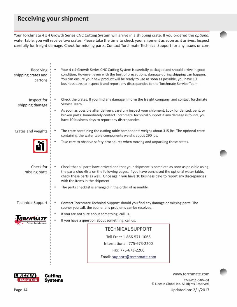
Receiving your shipment
Your Torchmate 4 x 4 Growth Series CNC Cutting System will arrive in a shipping crate. If you ordered the optional water table, you will receive two crates. Please take the time to check your shipment as soon as it arrives. Inspect carefully for freight damage. Check for missing parts. Contact Torchmate Technical Support for any issues or con-
Receiving shipping crates and
cartons
Inspect for shipping damage
y Your 4 x 4 Growth Series CNC Cutting System is carefully packaged and should arrive in good condition. However, even with the best of precautions, damage during shipping can happen. You can ensure your new product will be ready to use as soon as possible, you have 10 business days to inspect it and report any discrepancies to the Torchmate Service Team.
y Check the crates. If you find any damage, inform the freight company, and contact Torchmate Service Team.
y As soon as possible after delivery, carefully inspect your shipment. Look for dented, bent, or broken parts. Immediately contact Torchmate Technical Support if any damage is found, you have 10 business days to report any discrepancies.
y The crate containing the cutting table components weighs about 315 lbs. The optional crate containing the water table components weighs about 290 lbs.
y Take care to observe safety procedures when moving and unpacking these crates.
y Check that all parts have arrived and that your shipment is complete as soon as possible using the parts checklists on the following pages. If you have purchased the optional water table, check these parts as well. Once again you have 10 business days to report any discrepancies with the items in the shipment.
y The parts checklist is arranged in the order of assembly.
y Contact Torchmate Technical Support should you find any damage or missing parts. The sooner you call, the sooner any problems can be resolved.
y If you are not sure about something, call us.
y If you have a question about something, call us.
Crates and weights
TECHNICAL SUPPORT
Toll Free: 1-866-571-1066International: 775-673-2200
Fax: 775-673-2206Email: [email protected]

www.torchmate.com TMS-011-0404-01 © Lincoln Global Inc. All Rights Reserved.
Updated on: 2/1/2017 Page 15
Parts checklist
On the next few pages, the parts included in your Torchmate 4 x 4 Growth Series CNC Cutting System shipment are listed in the order you assemble them. To make it easier to complete the assembly of your cutting system, you can lay out the received parts in this order as you check them against this list.
Parts for the A-steps
Qty. Part Description Part Number Step1
GS 4' Side Set, Assembled (1 set = left and right),
TMS-180-1000-05 A1
18 Screw, BSCS, 5⁄16"–18 X 5/8" T-bolt TMS-410-5016-10 A1
14 T-nut, 5⁄16"–18, steel, black plated TMS-414-3101-16 A1
2 Aluminum cross-member - 4’ wide GS TMS-180-0002-09 A2
1 GS 4' Gantry, Assembled TMS-180-1000-03 A3
5 Screw, BSCS, 3⁄8"–16 X 1⁄2" TMS-410-0318-08 A7
2 Set of cable carrier end brackets TMS-105-0002-20 A8 & A10
1 Set of cable carrier brackets TMS-180-0002-07 A9
9 Screw, BSCS, #10-32 x 1⁄2" TMS-410-0511-08 A9
16 Washer, flat, #10, steel, zinc-plated TMS-413-0001-10 A9 & A10
16 Nut, Nylock, #10-32, steel, zinc-plated TMS-414-0201-11 A9 & A10
9 Screw, FSCS, #10-32 x 7⁄8" TMS-410-0111-14 A10
3 Screw, BSCS, #8-32 x 3/8" TMS-410-0208-06 A10
73 Mini Cable Carrier Links TMS-105-0002-19 A11

www.torchmate.com TMS-011-0404-01 © Lincoln Global Inc. All Rights Reserved.
Page 16 Updated on: 2/1/2017
Parts for the B-steps
Parts checklist (continued)
Qty. Part Description Part Number Step1 CNC controller, Accumove2 BK1250-200000 B1
1 24V 6.67A DC power supply, Accumove2 TMS-400-0003-02 B1
1 AC power cable TMS-402-0069-01 B1
1 Ethernet crossover cable, red, TMS-103-5000-07 B1
1 Laptop or PC with Microsoft Windows 10, Windows 8, or Windows 7, with a 64 bit operating system
(separate purchase)
B1
1 Cable, motor, JST / Molex 25' TMS-402-0071-25
3 Cable, motor, XLR / Molex, 25 ft TMS-402-0010-01 B2
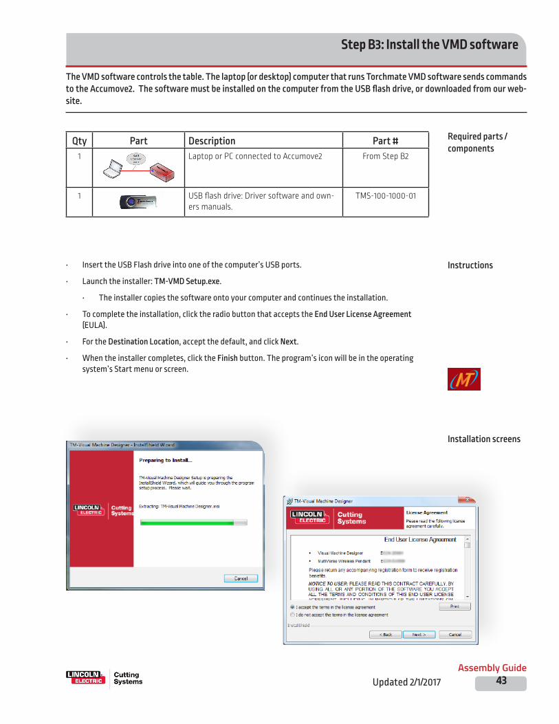
1 USB flash drive: Driver software and owners manuals.
TMS-100-1000-01 B3
4 99R6 ball bearings TMS-432-0010-01 B9
5 Screw, BSCS, 3⁄8"–16 X 1 TMS-410-0218-16 B9
www.torchmate.com TMS-011-0404-01 © Lincoln Global Inc. All Rights Reserved.
Updated on: 2/1/2017 Page 17
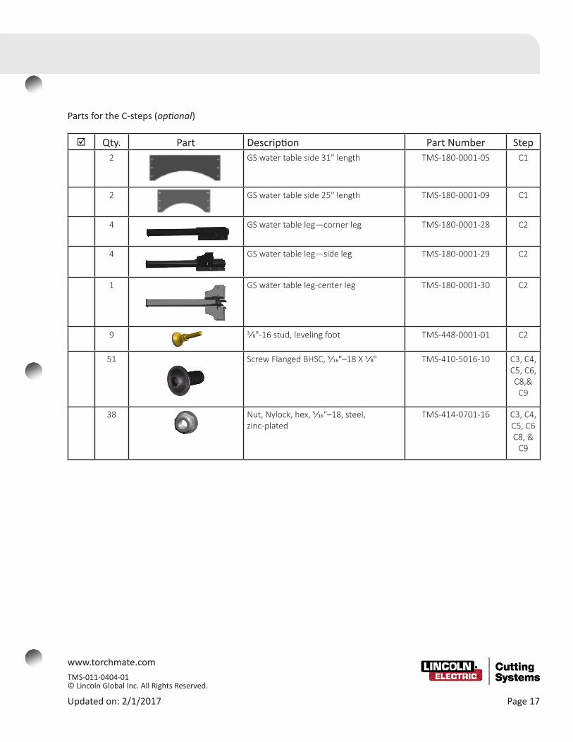
Parts for the C-steps (optional)
Qty. Part Description Part Number Step2 GS water table side 31" length TMS-180-0001-05 C1
2 GS water table side 25" length TMS-180-0001-09 C1
4 GS water table leg—corner leg TMS-180-0001-28 C2
4 GS water table leg—side leg TMS-180-0001-29 C2
1 GS water table leg-center leg TMS-180-0001-30 C2
9 3⁄8"-16 stud, leveling foot TMS-448-0001-01 C2
51 Screw Flanged BHSC, 5⁄16"–18 X 5⁄8" TMS-410-5016-10 C3, C4, C5, C6, C8,&
C9
38 Nut, Nylock, hex, 5⁄16"–18, steel, zinc-plated
TMS-414-0701-16 C3, C4, C5, C6 C8, &
C9

www.torchmate.com TMS-011-0404-01 © Lincoln Global Inc. All Rights Reserved.
Page 18 Updated on: 2/1/2017
Parts checklist (continued)
Qty. Part Description Part Number Step2 GS water table side 33.75" length TMS-180-0001-07 C4
2 GS water table side 22" length TMS-180-0001-08 C4
1 GS water table cross member—30 (medium)
TMS-180-0005-01 C4
1 GS water table cross member—24.75 (short)
TMS-180-0005-02 C4
1 GS water table cross member—57.625 (long)
TMS-180-0005-03 C5
1 GS water pan A - 4 x 4 with drain fitting
TMS-180-0001-64 C6
1 GS water pan B - 4 x 4 TMS-180-0001-73 C6
1 Growth Series Silicone Sealant, tube TMS-180-1001-01 C6
1 TFP-AR small table 3⁄4 plumbing (water release valve)
TMS-459-0010-01 C8
1 PTFE thread-sealant tape (recommended)
(separate purchase)
C6
N.A. 38 Slats—271⁄2" X 3" X 3⁄16" Customer supplied (you will cut these)
C6
5 Screw, BSCS, 3/8 - 16 X 1.0" TMS-410-0218-16 C8
5 Washer, flat 3/8" washer, steel, zinc-plated TMS-413-0001-18 C8
Parts for the C-steps (continued) (optional)

www.torchmate.com TMS-011-0404-01 © Lincoln Global Inc. All Rights Reserved.
Updated on: 2/1/2017 Page 19
Qty. Part Description Part Number Step1 90 Degree Tool Mounting plate TMS-180-0150-03 D1
1 Primary Tool Mounting plate TMS-180-0001-66
4 Screw, SCS 5/16-24 x 3/4" TMS-410-0017-20
2 Nut, Nylock, 5/16”-18, zinc-plated steel TMS-414-0701-16 D1
2 Screw, BSCS, 5/16-18 X 1”, hex drive TMS-410-0016-12 D1
1 Height Control Lifter, Accumove TMS-101-1100-02 D2
4 Screw, SCS, 5⁄16”-18 X 1.0” lg, hex drive TMS-410-0016-16 D2
1 Plasma cutter power supply unit Purchased separately
D3
1 CNC Interface cable Supplied with plasma cutter
D3
1 Height Control VFC/Relay TMS-101-1100-01 D4
1
Arc Voltage/Ohmic Cable TMS-101-1109-01 D5
1 Height control cable TMS-103-5000-01 D5
1 12 AWG Chassis ground wire 25' From your toolbox D5?
1 Ohmic Cap (torch consumable stack)
Depends on plasma power unit
D5
1 Raw arc voltage cable (included with CNC Interface cable for Lincoln Electric plasma power units)
Depends on plasma power unit
D5
4 Terminal Block Plug 2Pos Str 5.08mm TMS-403-0076-01 D6
Parts for the D-steps

www.torchmate.com TMS-011-0404-01 © Lincoln Global Inc. All Rights Reserved.
Page 20 Updated on: 2/1/2017
Qty. Part Description Part Number1 3⁄8" wrench (from your toolkit)
1 1⁄2" wrench (from your toolkit)
1 9⁄16" wrench (from your toolkit)
1 5⁄32" to 1⁄4" hex key set (from your toolkit)
1 Tape measure (from your toolkit)
1 Battery power for computer (Uninterruptible power supply or UPS) —with surge protection
(recommended separate
purchase)
Additional required equipment and tools
Parts checklist (continued)

www.torchmate.com TMS-011-0404-01 © Lincoln Global Inc. All Rights Reserved.
Updated on: 2/1/2017 Page 21
Torchmate's Product Family
www.torchmate.com TMS-011-0404-01 © Lincoln Global Inc. All Rights Reserved.
Page 22 Updated on: 2/1/2017
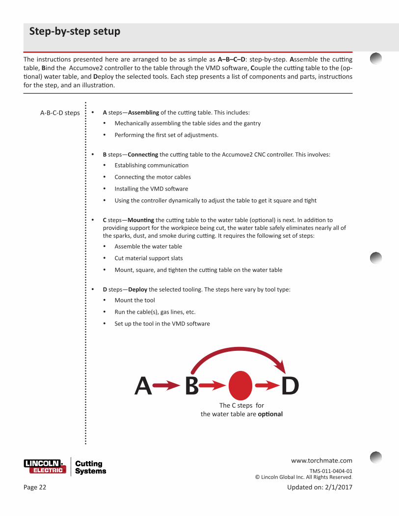
A B C DThe C steps for
the water table are optional
Step-by-step setup
The instructions presented here are arranged to be as simple as A–B–C–D: step-by-step. Assemble the cutting table, Bind the Accumove2 controller to the table through the VMD software, Couple the cutting table to the (op-tional) water table, and Deploy the selected tools. Each step presents a list of components and parts, instructions for the step, and an illustration.
A-B-C-D steps y A steps—Assembling of the cutting table. This includes:
y Mechanically assembling the table sides and the gantry
y Performing the first set of adjustments.
y B steps—Connecting the cutting table to the Accumove2 CNC controller. This involves:
y Establishing communication
y Connecting the motor cables
y Installing the VMD software
y Using the controller dynamically to adjust the table to get it square and tight
y C steps—Mounting the cutting table to the water table (optional) is next. In addition to providing support for the workpiece being cut, the water table safely eliminates nearly all of the sparks, dust, and smoke during cutting. It requires the following set of steps:
y Assemble the water table
y Cut material support slats
y Mount, square, and tighten the cutting table on the water table
y D steps—Deploy the selected tooling. The steps here vary by tool type:
y Mount the tool
y Run the cable(s), gas lines, etc.
y Set up the tool in the VMD software

www.torchmate.com TMS-011-0404-01 © Lincoln Global Inc. All Rights Reserved.
Updated on: 2/1/2017 Page 23
Illustrations
List parts and components
y On previous pages you were provided a parts list, organized to help you receive parts. The location, in terms of the numbered steps that follow were also listed so you can quickly locate the step that uses a particular part.
y Each of the assembly steps that follow provides its own list of parts or components, including the quantity required for that step.
y Should you require additional quantities of any part, please contact Torchmate Technical Support.
y Torchmate Technical support is available Monday through Friday from 6 AM to 4 PM (06:00 to 16:00, Pacific Time Zone.
Toll Free: 1-866-571-1066International: 775-673-2200
Fax: 775-673-2206Email: [email protected]
Written instructions
y Detailed instructions are provided for each assembly step.
y If you ever find the instructions unclear, please contact Torchmate Technical Support and let us know, so that we can not only give you immediate assistance, but so that we can also make improvements to the instructions.
y For each step in the assembly, illustrations will guide you. For some illustrations, additional close up views are provided.
y The assembly action is often illustrated with an exploded-diagram.

www.torchmate.com TMS-011-0404-01 © Lincoln Global Inc. All Rights Reserved.
Page 24 Updated on: 2/1/2017
Toll Free: 1-866-571-1066International: 775-673-2200
Fax: 775-673-2206Email: [email protected]
y When building the table, if a question or concern arises or a part is missing, please contact Torchmate Technical Support.
y Technical Support will also help you with operating the CNC system, and troubleshooting problems.
y Torchmate Technical Support is available Monday through Friday from 7 AM to 4 PM (07:00 to 16:00), Pacific Time Zone.
Call, Fax, or Email
Technical Support
Call us for Consumables,
or visit our web store
www.TorchmateStore.com

www.torchmate.com TMS-011-0404-01 © Lincoln Global Inc. All Rights Reserved. 1170 Trademark Drive | Reno, NV 89521 | USA Phone: 775-673-2200 | 866-571-1066
Updated on: 2/1/2017 Page 25
Assembling the cutting table
www.torchmate.com TMS-011-0404-01 © Lincoln Global Inc. All Rights Reserved.
Page 26 Updated on: 2/1/2017
Assembly overview
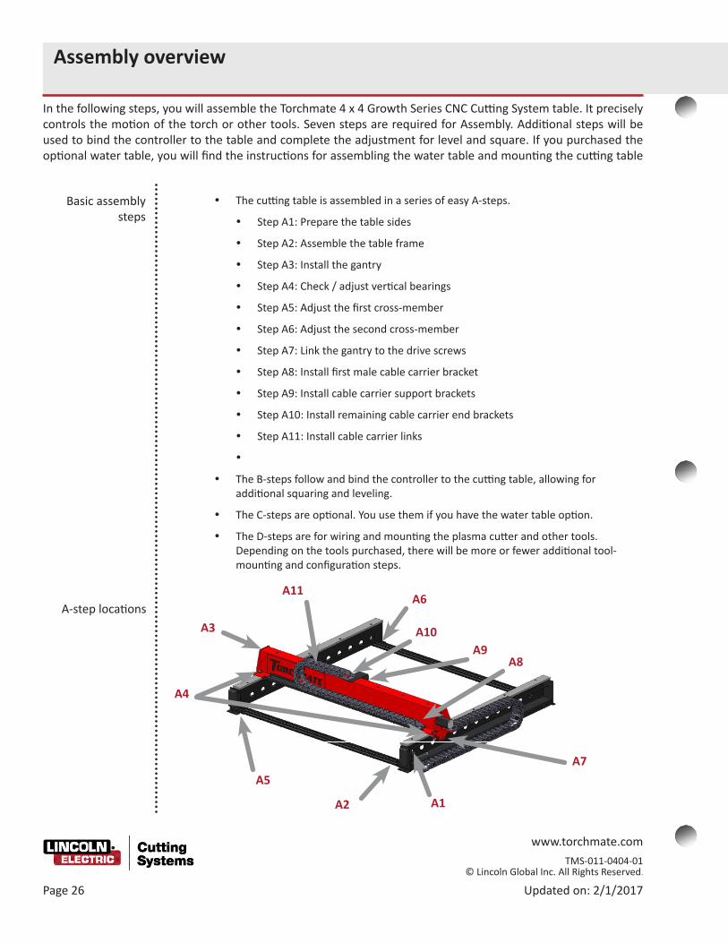
In the following steps, you will assemble the Torchmate 4 x 4 Growth Series CNC Cutting System table. It precisely controls the motion of the torch or other tools. Seven steps are required for Assembly. Additional steps will be used to bind the controller to the table and complete the adjustment for level and square. If you purchased the optional water table, you will find the instructions for assembling the water table and mounting the cutting table
Basic assembly steps
y The cutting table is assembled in a series of easy A-steps.
y Step A1: Prepare the table sides
y Step A2: Assemble the table frame
y Step A3: Install the gantry
y Step A4: Check / adjust vertical bearings
y Step A5: Adjust the first cross-member
y Step A6: Adjust the second cross-member
y Step A7: Link the gantry to the drive screws
y Step A8: Install first male cable carrier bracket
y Step A9: Install cable carrier support brackets
y Step A10: Install remaining cable carrier end brackets
y Step A11: Install cable carrier links
y
y The B-steps follow and bind the controller to the cutting table, allowing for additional squaring and leveling.
y The C-steps are optional. You use them if you have the water table option.
y The D-steps are for wiring and mounting the plasma cutter and other tools. Depending on the tools purchased, there will be more or fewer additional tool-mounting and configuration steps.
A-step locations
A1A2
A3
A4
A5
A6
A7
A10A9
A8
A11

www.torchmate.com TMS-011-0404-01 © Lincoln Global Inc. All Rights Reserved.
Updated on: 2/1/2017 Page 27
Weight of the completed CNC cutting table with optional water table (before adding water)
Weight of completed CNC cutting table
175 lbs80 kg
y The completed CNC cutting table is sturdy and heavy-duty, so that it can precisely and accurately move the torch, support your material, and support the weight of the water in the water table reservoir.
y After being removed from the crate, the combined weight is 450 lbs (204 kg), before adding water.
y Whether full or empty of water, do not drag the cutting table when moving it to a new location.
y If you drag the CNC cutting table / water table , you can damage it and get it out of square.
y Do not try to move the cutting table without help. When you must re-position the CNC cutting table / water table or move it to a new location, drain all the water and use the proper equipment to carefully lift it.
450 lbs 204 kg

www.torchmate.com TMS-011-0404-01 © Lincoln Global Inc. All Rights Reserved.
Page 28 Updated on: 2/1/2017
Step A1: Prepare table sides
The sides of your Torchmate 4 x 4 Growth Series CNC Cutting System are pre-assembled with a drive-screw, motor, and steel rails. The cross-members are extruded aluminum channels which are held to the sides with T-nuts. Here you will prepare sides by adding the T-nuts. In the next step you will add the cross-members.
Qty Part Description Part #1
GS 4' side set, assembled, (L / R set)
TMS-180-1000-05
12 Screw, BSCS, 5⁄16"–18 x 5⁄8" T-bolt TMS-410-5016-10
12 T-nut, 5⁄16"–18, steel, black plated TMS-414-3101-16
Required parts / components
Instructions
Illustration
y On each end of each pre-assembled side, insert three 5⁄16"–18 x 5⁄8" button head screws through the holes from the outside.
y Fasten a 5⁄16"–18 T-nut to each screw.
y Leave the nuts loose on the screws.
y The T-nuts should be positioned so that the flanges (raised portions) face away from the screws.
www.torchmate.com TMS-011-0404-01 © Lincoln Global Inc. All Rights Reserved.
Updated on: 2/1/2017 Page 29
Step A2: Assemble table frame
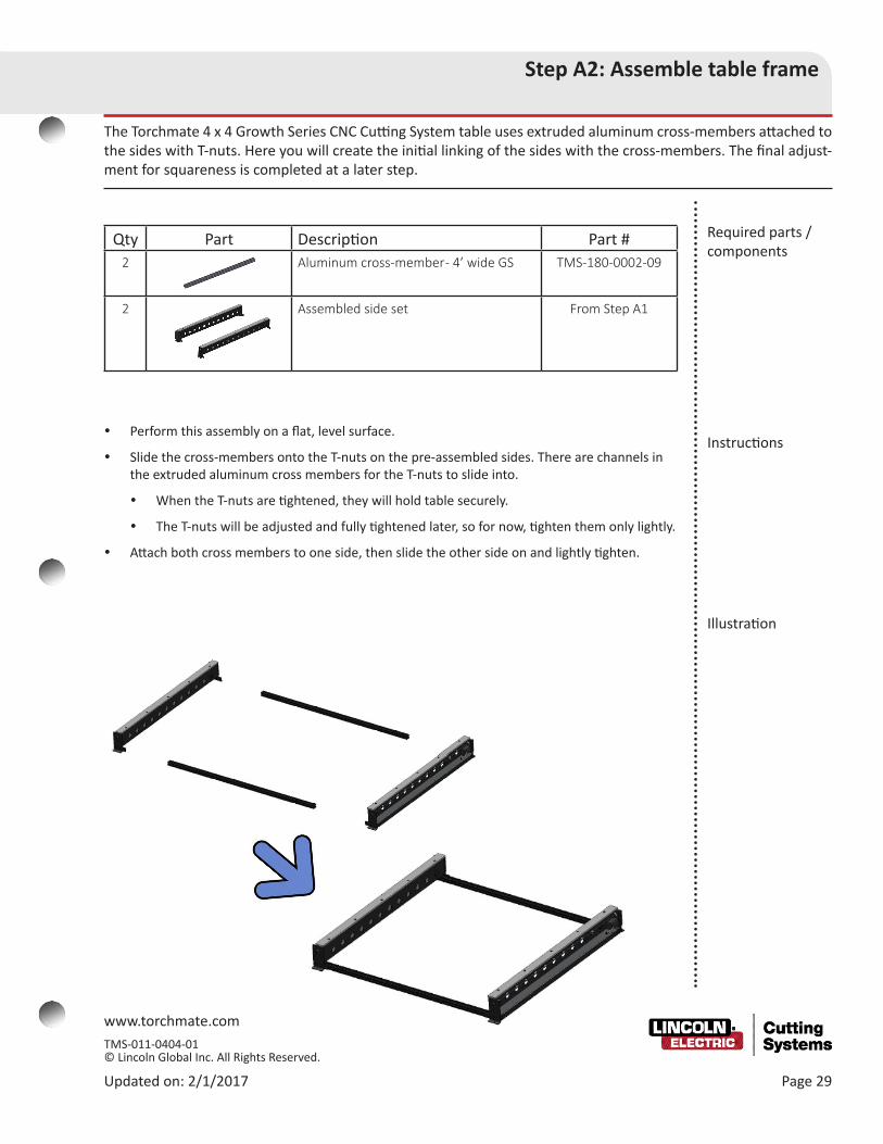
The Torchmate 4 x 4 Growth Series CNC Cutting System table uses extruded aluminum cross-members attached to the sides with T-nuts. Here you will create the initial linking of the sides with the cross-members. The final adjust-ment for squareness is completed at a later step.
Required parts / components
Instructions
Illustration
Qty Part Description Part #2 Aluminum cross-member - 4’ wide GS TMS-180-0002-09
2 Assembled side set From Step A1
y Perform this assembly on a flat, level surface.
y Slide the cross-members onto the T-nuts on the pre-assembled sides. There are channels in the extruded aluminum cross members for the T-nuts to slide into.
y When the T-nuts are tightened, they will hold table securely.
y The T-nuts will be adjusted and fully tightened later, so for now, tighten them only lightly.
y Attach both cross members to one side, then slide the other side on and lightly tighten.

www.torchmate.com TMS-011-0404-01 © Lincoln Global Inc. All Rights Reserved.
Page 30 Updated on: 2/1/2017
Step A3: Install the gantry
Like the sides of the Torchmate 4x4 Growth Series CNC Cutting System table, the full gantry is pre-assembled with a drive-screw, motor, and steel rail. In this step, you will set the gantry on the side rails.
Qty Part Description Part #1 GS 4' Gantry Assembled TMS-180-1000-03
1 Assembled frame components From Step 2
Required parts / components
Instructions
Illustration
y Loosen the inner and outer bearings so that they can be moved outward to give clearance for the rail.
y Set the gantry onto the sides over the rails. Make sure the vertical bearings are taking the weight of the gantry and that it is free to move.
y Ensure that the gantry’s tool-mounting plate faces away from the motors on the end of the two sides.

www.torchmate.com TMS-011-0404-01 © Lincoln Global Inc. All Rights Reserved.
Updated on: 2/1/2017 Page 31
Step A4: Check / adjust vertical bearings
The smooth motion of the Torchmate 4 x 4 Growth Series CNC Cutting System gantry is managed by the four ver-tical bearings that carry the gantry’s weight. In this step you check the gantry’s clearance above the side rails and adjust its height, if necessary, by moving the vertical bearings.
Illustration
Instructions
Qty Part Description Part #1 Assembled cutting table From Step A3
Required parts / components
y Measure the front and back clearances between each gantry end and the rails (four total measurements).
y A clearance of approximately 1⁄8" (0.125") is desired.
y Hint: The thickness of a new penny and a new dime (0.114") or two new pennies (0.122") is a good beginning clearance.
y Loosen and adjust each vertical bearing, as necessary, to achieve an equal clearance of approximately 1⁄8" at each location.
y Tighten the vertical bearings fully.
y Note: the vertical bearings may require further adjustment in a later step.
Measure here for1/8" Clearance
Loosen this bolt to adjust the clearance height

www.torchmate.com TMS-011-0404-01 © Lincoln Global Inc. All Rights Reserved.
Page 32 Updated on: 2/1/2017
Step A5: Adjust the first cross-member
With the gantry positioned on your Torchmate 4 x 4 Growth Series CNC Cutting System table, you can now begin to adjust the table’s squareness and begin to tighten the cross-members. Squaring is essential for smooth and accurate gantry operation.
Qty Part Description Part #1 Assembled cutting table From Step A4
Required parts / components
Instructions
Illustration
y Slide the gantry to one end of the table until it reaches the stops.
y On each side rail, rotate the drive screw to move the aluminum brackets. Align the bracket holes with the gantry holes.
y If there is a gap between the bracket and the gantry, slide the sides outward in the cross-member channel until the gantry and bracket just touch with no pressure.
y If there is tightness between the bracket and the gantry, slide the sides inward in the cross-member channel until the gantry and bracket just touch with no pressure.
y Tighten one of the T-bolts on each end of the adjusted cross-member.
With the gantry at its stop and the bracket holes aligned with the gantry holes, check between the gantry and bracket for a gap or for tightness. They should just touch on both
If tight, slide inward
If a gap, slide outward
When adjusted, tighten one T-bolt at each end of the cross

www.torchmate.com TMS-011-0404-01 © Lincoln Global Inc. All Rights Reserved.
Updated on: 2/1/2017 Page 33
Step A6: Adjust the second cross-member
With the gantry secured to your Torchmate 4 x 4 Growth Series CNC Cutting System table, you can now adjust the table’s squareness and securely tighten the cross-members. When squared, the gantry will operate smoothly and accurately.
Qty Part Description Part #1 Assembled cutting table From Step A5
1 Tape measure (From your toolbox)
Required parts / components
Instructions
Illustration
y Measure the distance between the outside edges of the rails at the gantry end.
y Measure the distance between the outside edges of the rails at the other (non-gantry) end.
y Adjust side rails in the cross-members at the other (non-gantry) end to make both measurements the same (within ±1/32").
y Re-check the measurements, and make diagonal (corner to corner) measurements to ensure the table is square (within ±1/32").
y Tighten all T-bolts on both cross-members.
First, measure here—outside of rail to outside of rail
Second, measure here. Adjust this end’s rail spacing to make both

www.torchmate.com TMS-011-0404-01 © Lincoln Global Inc. All Rights Reserved.
Page 34 Updated on: 2/1/2017
Step A7: Link the gantry to the drive screws
Your Torchmate 4 x 4 Growth Series CNC Cutting System achieves accuracy and precision in cutting complex shapes because it uses anti-backlash nuts, which minimize backlash (play) on its drive screws. Here you will attach the gantry to the side rail drive screw brackets.
Qty Part Description Part #1 Squared cutting table From Step A6
4 Screw, BSCS, 3⁄8"–16 X 1⁄2" TMS-410-0318-08
Required parts / components
Instructions
Illustration
y Check that you can bolt the gantry to the aluminum bracket without applying vertical force.
y If the holes do not align vertically, adjust the gantry clearance by re-positioning the vertical bearings.
y The bearings should support the entire weight of the gantry, leaving the drive screw free to rotate without any binding.
y Attach the gantry to the aluminum anti-backlash drive screw brackets on both sides of the table using button head screws.
y Fully tighten the screws to secure the gantry to the table.
y Note: With the gantry linked to the drive screws, only move the gantry using software jogging or programmed motor control. Don’t try to move the gantry by hand.
www.torchmate.com TMS-011-0404-01 © Lincoln Global Inc. All Rights Reserved.
Updated on: 2/1/2017 Page 35
Step A8: Install first male cable carrier bracket
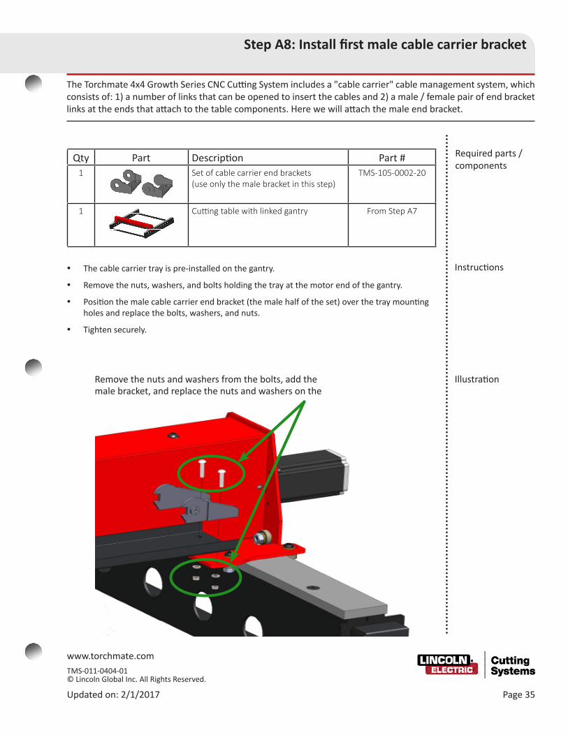
The Torchmate 4x4 Growth Series CNC Cutting System includes a "cable carrier" cable management system, which consists of: 1) a number of links that can be opened to insert the cables and 2) a male / female pair of end bracket links at the ends that attach to the table components. Here we will attach the male end bracket.
y The cable carrier tray is pre-installed on the gantry.
y Remove the nuts, washers, and bolts holding the tray at the motor end of the gantry.
y Position the male cable carrier end bracket (the male half of the set) over the tray mounting holes and replace the bolts, washers, and nuts.
y Tighten securely.
Required parts / components
Instructions
Qty Part Description Part #1 Set of cable carrier end brackets
(use only the male bracket in this step)TMS-105-0002-20
1 Cutting table with linked gantry From Step A7
Remove the nuts and washers from the bolts, add the male bracket, and replace the nuts and washers on the
Illustration

www.torchmate.com TMS-011-0404-01 © Lincoln Global Inc. All Rights Reserved.
Page 36 Updated on: 2/1/2017
Step A9: Install cable carrier support brackets
The Torchmate Growth Series 4x4 cable carrier system uses two lengths of cable carriers to manage cables: one runs along one rail and the other along the gantry. The pre-installed tray supports the carrier along the gantry. Additional support brackets, mounted in this step, support the carrier along the rails, at the end of the gantry, and on the tool mounting plate.
y Use the screws, washers, and nuts (at the end of the gantry, use the #8 threaded holes instead of nuts and washers) to attach the cable carrier support brackets to the rails (x3), the gantry end (x1), and the tool mounting plate(x1).
Required parts / components
Instructions
Qty Part Description Part #1 Set of cable carrier brackets TMS-180-0002-07
10 Screw, BSCS, 10-32 x 1⁄2" TMS-410-0511-08
8 Washer, flat, #10, steel, zinc-plated TMS-413-0001-10
8 Nut, Nylock, 10-32, steel, zinc-plated TMS-414-0201-11
2 Screw, BSCS, 8-32 x 3/8" TMS-410-0208-06
1 Cutting table with cable carrier end bracket on tray
From Step A8
(1) Mount the large cable carrier on the tool mount-ing plate,
(2) Mount the red bracket on the gantry end's thread-ed holes,
(3) Mount the small bracket with holes nearest the motor along the rail,
(4) Mount the remaining two support brackets along the rail.
Shown from below
Illustration

www.torchmate.com TMS-011-0404-01 © Lincoln Global Inc. All Rights Reserved.
Updated on: 2/1/2017 Page 37
Step A10: Install remaining cable carrier end brackets
The cable carrier has two sections of links that attach to the table by means of end brackets. These end brackets are similar to regular cable carrier links in the way they snap together, but they are also bolted to the support brackets installed in Step A9.
y Install the remaining 3 cable carrier end brackets onto the cable carrier support brackets, securing them with screws, washers, and locking nuts.
y The end brackets open ends should face the same direction, as illustrated, These will be used to attach the cable carrier links in the next step.
Required parts / components
Instructions
Qty Part Description Part #2 Set of CC end brackets (one male bracket
from one set was used in Step A8)TMS-105-0002-20
6 Screw, FSCS, 10-32 x 7⁄8" TMS-410-0111-14
6 Washer, flat, #10, steel, zinc-plated TMS-413-0001-10
6 Nut, Nylock, 10-32, steel, zinc-plated TMS-414-0201-11
1 Cutting table with support brackets From Step A9
Mount the cable carrier end brackets so that a male and female bracket are on each of the two runs, facing the same direction.
Mount cable carrier end brackets here
Illustration

www.torchmate.com TMS-011-0404-01 © Lincoln Global Inc. All Rights Reserved.
Page 38 Updated on: 2/1/2017
Step A11: Install cable carrier links
The 4x4 Growth Series cutting table includes two sections of cable carrier with snap-together links. They snap to the end brackets, installed in Steps A8 and A10, and to each other. The links can be popped open with a screw-driver (from either side) so that the motor-control and other cables can be put inside the carrier. We recommend the plasma torch cable be tied to the side.
y The cable carrier links snap together. You may find it easier to open the links, set the cables inside, and close the links before attaching the chain to the table.
y Snap a 38 link chain to the side, resting it on the support brackets
y Snap a 35 link chain to the gantry, resting it on the tray
y Keep the motor (and other signal) cables as far away from the torch cable as possible to reduce EMI. Our recommendation is to tie the torch cable to the outside of the carriers. Tie-zips are not included.
Required parts / components
Instructions
Qty Part Description Part #73 Mini cable carrier links (10.84 feet) TMS-105-0002-19
1 Cutting table with CC end brackets From Step A10
The links lie in a chain along the gantry tray and
along the rail brackets.
Snap the links open to put the cables inside, close, then snap the links to the end brackets
You may tie the torch lead to the outside of the
carrier links to help reduce Electromagnetic Interference
Illustrations

Assembly Guide39Updated 2/1/2017
Binding the Accumove™2

Torchmate Growth Series40
Overview of wiring
Summary • The Accumove 2 controller is the destination for the table's motor cables and the computer's Ethernet crossover cable. The cable ends are ready to plug in to the back of the box.
• The Accumove 2 box should be located so that it is not exposed to cutting spatter (or splashing from a water table), and so that the motor cables do not need to be coiled.
• Coiled cables can introduce troublesome noise into the electronic signals and should be avoided.
Illustration of initial wiring needed
for table motion
Preview of wiring needed for
typical table oper-ation with Lincoln
Plasma Cutter
The following section contains information for wiring the Growth Series CNC Cutting System table.

Assembly Guide41Updated 2/1/2017
Step B1: Run crossover Ethernet cable
The Torchmate Accumove 2 communicates with the VMD (CAM/Computer Aided Machining) software that runs on the com-puter using a Crossover Ethernet cable connection. An Ethernet crossover cable (red) is provided that requires no other net-work devices to establish communication.
• The Accumove 2 CNC controller comes with a power supply and a red crossover Ethernet communication cable.
• A regular Ethernet cable cannot be used in place of the crossover cable. The wires arrive in a different order on the connectors. Be sure to use the red crossover Ethernet cable to connect directly from the computer to the Accumove 2 CNC controller.
• Run the red crossover cable from the computer's Ethernet port to the active (right-hand) port on the Accumove 2 CNC controller box. The left-hand port is inactive for connecting to the laptop (or PC).
Required parts / components
Instructions
Qty Part Description Part #1 Accumove 2 BK1250-200000
1 24V 6.67A DC power supply, TMS-400-0003-02
1 AC power cable TMS-402-0069-01
1 Crossover Ethernet cable TMS-103-5000-07
1 Laptop or PC with Microsoft Windows 10, Windows 8, Windows 7, 64 bit operating system
(separate purchase)
Direct connection with the crossover cable
Only use the right-hand Ethernet port on the Accumove 2 control-ler
Inactive port
Active port

Torchmate Growth Series42
Step B2: Run motor cables
The four motors that move the gantry and the torch upon the gantry receive their power and control signals from the Accu-move 2 box. You will connect the motor cables using the guide below.
Required parts / components
Instructions
Connect motor cables in the
indicated order:
1 = gantry motor
2 = rail axis
3 = Z-axis / AVHC
4 = rail axis
Qty Part Description Part #1 Squared cutting table From Step A7
1 Computer and Accumove (with X-over Ethernet cable)
From Step B1
3 Cables, motor, Molex / XLR, 25 ft TMS-402-0010-01
1 Cable, motor, JST / Molex 25 ft TMS-402-0071-25
• Connect the motors to the Accumove 2 controller with the 25 ft. motor cables. Use the diagram below to determine which motor cable is installed where, these cables are not color coded.
• Note: The Z axis motor cable has a different motor cable connection, this is a "Flat" 6 pin connector.
• The cables will "click" into place.
• To avoid electronic noise, be careful not to pinch or cut the wire, especially near the connectors at either end, and avoid coiling or crossing the wires. Strain relief the Z axis motor cable at the connection.
• IMPORTANT: Never connect or disconnect a motor cable while the Accumove 2 is powered on. This will cause irreversible damage to the Accumove 2
Assembly Guide43Updated 2/1/2017
Step B3: Install the VMD software
The VMD software controls the table. The laptop (or desktop) computer that runs Torchmate VMD software sends commands to the Accumove2. The software must be installed on the computer from the USB flash drive, or downloaded from our web-site.
• Insert the USB Flash drive into one of the computer’s USB ports.
• Launch the installer: TM-VMD Setup.exe.
• The installer copies the software onto your computer and continues the installation.
• To complete the installation, click the radio button that accepts the End User License Agreement (EULA).
• For the Destination Location, accept the default, and click Next.
• When the installer completes, click the Finish button. The program’s icon will be in the operating system’s Start menu or screen.
Qty Part Description Part #1 Laptop or PC connected to Accumove2 From Step B2
1 USB flash drive: Driver software and own-ers manuals.
TMS-100-1000-01
Required parts / components
Instructions
Installation screens

Torchmate Growth Series44
Step B4: Set the IP address
For security, the Accumove2 controller restricts its communication to only a computer with a known (static) IP address run-ning the Accumove2 software. The controller itself also uses a static address.
• The first time you use the Accumove 2, its IP address is pre-set to 192.168.1.7 and it also requires the computer to use 192.168.1.6. After installing the crossover cable, set the computer’s address.
• From your computer's Control Panel, open the Network and Sharing control panel. On the left side, select Change Adapter Settings.
• In the Network Connections window, disable all connections except for Local Area Connection by right clicking on the icon(s) and selecting Disable.
• Right click on the Local Area Connection and select Properties. Select Internet protocol version 4 (TCP/IPv4). Select the Properties button below the list.
• Select Use the following IP address. Enter 192.168.1.6 in the IP address field. Press the Tab key to fill in the Subnet mask. Click OK to save.
• Power on the Accumove 2, then start the VMD software.
Qty Part Description Part #1 GS Table, computer with VMD software,
and Accumove 2From Step B3
Required parts / components
Instructions
Installation screens
Select Use the following IP address
Disable all connections except the Accu-move 2. To check, unplug/replug the red cable

Assembly Guide45Updated 2/1/2017
Step B5: Start the Accumove 2 and log on to VMD
So that the VMD can begin communicating position information with the Accumove 2, the first requirement is to complete the machine setup by loading the configuration file. The VMD software protects your machine setup by requiring an "Admin" user name and password to log on before allowing configuration changes.
Qty Part Description Part #1 GS Table, computer and Accumove 2 with
crossover cable, and IP addressFrom Step B4
Required parts / components
Instructions• IMPORTANT: Never connect or disconnect a motor cable while the Accumove 2 is powered on. This will cause irreversible damage to the Accumove 2.
• To properly power on the system, first power on the Accumove 2 control box, wait 15 seconds, and open the Torchmate VMD software.
• A notice box requests "Please switch the drives on." Click Hide. The drives are automatically switched on when the table Datum is set in a later step.
• Click the Log On button to bring up the log on screen. Select the Admin user name and enter the password for that name. When the Accumove 2 is first powered up, the default password for the Admin user is "1234." This may be changed to protect the Accumove 2 from configuration changes by unauthorized personnel.
• The Operator user name requires no password by default, but this may be changed as well.
• When the Admin user log on is completed, you will see a new button on the Run screen labeled Machine Settings.
User name / pass-word screens
The Machine Settings button will appear here

Torchmate Growth Series46
Step B6: Load configuration file for table
The configuration for each type of table and each type of tool is saved in a configuration file. Here we will find the file for this table and tool combination and load it.
Required parts / components
Qty Part Description Part #1 GS Table, computer and Accumove 2
(logged in)
From Step B5
Instructions • Click on the Machine Settings button to display the Configuration control panel, then click the Load Configuration button.
• Select the your machine's configuration file, and click OK.
• Unless your table is reconfigured, you will not need to change any of the settings.
Click the Load Configuration
button
Click on the appropriate file
name for your machine
to highlight it, then click OK
Illustrations
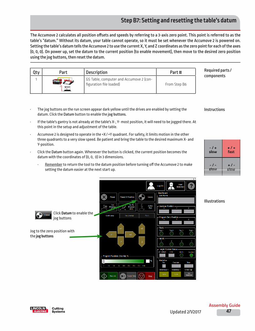
Assembly Guide47Updated 2/1/2017
The Accumove 2 calculates all position offsets and speeds by referring to a 3-axis zero point. This point is referred to as the table’s “datum.” Without its datum, your table cannot operate, so it must be set whenever the Accumove 2 is powered on. Setting the table’s datum tells the Accumove 2 to use the current X, Y, and Z coordinates as the zero point for each of the axes (0, 0, 0). On power up, set the datum to the current position (to enable movement), then move to the desired zero position using the jog buttons, then reset the datum.
Step B7: Setting and resetting the table's datum
Required parts / components
Instructions
Illustrations
• The jog buttons on the run screen appear dark yellow until the drives are enabled by setting the datum. Click the Datum button to enable the jog buttons.
• If the table's gantry is not already at the table's X-, Y- most position, it will need to be jogged there. At this point in the setup and adjustment of the table.
• Accumove 2 is designed to operate in the +X / +Y quadrant. For safety, it limits motion in the other three quadrants to a very slow speed. Be patient and bring the table to the desired maximum X- and Y-position.
• Click the Datum button again. Whenever the button is clicked, the current position becomes the datum with the coordinates of (0, 0, 0) in 3 dimensions.
• Remember to return the tool to the datum position before turning off the Accumove 2 to make setting the datum easier at the next start up.
Qty Part Description Part #1 GS Table, computer and Accumove 2 (con-
figuration file loaded)
From Step B6
Click Datum to enable the jog buttons
Jog to the zero position with the jog buttons

Torchmate Growth Series48
Once the VMD software is installed and configured, the table can be moved under software control. This step positions the inner and outer side bearings using the motion of the gantry, and it checks for any movement problems as adjusted at normal speeds.
Step B8: Jog gantry to set side bearings
Required parts / components
Qty Part Description Part #1 GS Table, computer and Accumove 2 (with
datum set)From Steps A7 and B7
Instructions
TECHNICAL SUPPORT
Toll Free: 1-866-571-1066
International: 775-673-2200
Fax: 775-673-2206
Email: [email protected]
If the gantry binds, contact Torchmate
Technical Support
Close-up of Jogging arrows Use the Y-axis arrow
keys to jog the gantry to each end of the table
• The nuts holding the inner and outer gantry side bearings should be loose enough to move with a little pressure, but not so loose they "rattle." The gantry should still be at one end.
• At each rail, move the inner and outer bearings toward the rail so they just touch the rails.
• Open the VMD software and Datum the table.
• Click the Job Setup button.
• Click the -Y and +Y buttons to move the gantry from one end of the table to the other. As the bearings have not been tightened, they will adjust during the movement, as needed.
• Use the jog Arrow buttons to move the gantry to the other end of the table. If there are any clearance issues with the side bearings, they will self-adjust.
• Without moving the side bearings from where they self-adjusted, tighten the inner and outer side bearings at each end of the gantry.

Assembly Guide49Updated 2/1/2017
Qty Part Description Part #1 Assembled side and gantry components
(with side bearings set)From Step B8
4 99R6 ball bearings TMS-432-0010-01
4 Screw, BSCS, 3⁄8"–16 X 1 TMS-410-0218-16
4 Nut, Nylock, 3⁄8"–16 steel, zinc-plated TMS-414-0201-18
16 Washer, flat, 3⁄8", steel, cadmium- plated
TMS-413-0406-18
Step B9: Add underside bearings (optional)
Required parts / components
Instructions
You can help prevent the gantry from being lifted from the rails during material sensing by installing underside roller bearings. The top and side bearings are pre-installed on the gantry, but you must add the underside bearings for routing configurations.
Illustration
• Assemble four roller bearings on the underside of the gantry, two on each side. Each assembly includes: a button head screw, four washers, a roller bearing, and a hex nut.
• Pass the screw through one washer, then through the gantry. On the inside of the gantry, place two washers on the screw, followed by the bearing, another washer, and the hex nut.
• Position the roller bearings so that they make only light contact with the underside of the rails when moved through the full gantry travel, and then tighten them fully.
Underside roller-bearing

Torchmate Growth Series50
The Torchmate Growth Series CNC Cutting System table should now be about ready for deploying tools. This step tests for any binding or problems with moving the gantry at fully adjusted operational speeds.
Step B10: Test jog gantry at high speed
Required parts / components
Qty Part Description Part #1 GS Table, computer and Accumove2 (with
side bearings set)From Steps B8 or B9
Instructions • Open the VMD software and Datum the table.
• Click the -Y and +Y buttons to move the gantry from one end of the table to the other. Because the side bearings have not been tightened down, they should adjust their position during the movement.
• The gantry should move freely. If so, tighten the bearing nuts, maintaining and re-checking the bearing positions.
• Select Fast jogging speed by clicking the arrow and dragging toward the arrowhead. The closer you click to the tip of the arrow the faster the machine moves in that direction.
• Closely observe and listen while the gantry moves.
• If there is any binding or if the motors are “fighting” each other, stop the test and contact Torchmate Technical Support.
TECHNICAL SUPPORT
Toll Free: 1-866-571-1066
International: 775-673-2200
Fax: 775-673-2206
Email: [email protected]
If the gantry binds, contact Torchmate
Technical Support
Close-up of Jogging arrows
Use the Y-axis arrow keys to jog the gantry to each end of the table

Assembly Guide51Updated 2/1/2017
This general discussion describes the additional connections that prepare the table for plasma cutting.
Typical additional wiring steps
Required parts / components
Qty Part Description Part #1 GS Table, computer and Accumove 2 (test-
ed at high speed)(multiple)
Instructions• See section D - Deploying Tools. If you are adding a plasma cutter, you will:
• Mount and attach the torch to the gantry• Bolt the AVHC Breakaway unit to the Z axis column• Connect the magnetic breakaway cable and Z axis limit switch• Connect the height control cable between the VFC unit and the Accumove 2.
• Connect the torch relay wires in the plasma cutter's CNC cable to the Accumove 2.• Make the connections from the plasma cutter's CNC interface cable to the VFC unit and also to
the Accumove2.• Connect ground wires from the VFC unit and the Accumove 2 controller to your star ground• Run the torch lead from the plasma cutter to the gantry torch mount. Keep the torch lead as far
as possible from the motor cables to reduce EMI.• Provide the plasma power supply with appropriate power and air/gas connections.• Run the work lead to the workpiece directly, shorten this cable if there is excess length coiled.
• Note: Electrical noise in a busy shop can be a problem for table operation. If you are advised to install a direct earth/ground rod-to-table cable, consult a qualified electrical worker to ensure code compliance. Refer to our EMI Reduction information.
• If you are adding other types of tools, consult the manuals that accompany those tools for mounting and configuration instructions.
Torch connections

Mounting the Water Table (optional)
Page 54

www.torchmate.com TMS-011-0404-01 © Lincoln Global Inc. All Rights Reserved.
Updated on: 2/1/2017 Page 55
Assemble the (optional) 4 x 4 water table
In the following steps, you will assemble the water table if you purchased this option. The water table supports the CNC cut-ting table, supports the workpiece being cut, and safely eliminates nearly all of the sparks, dust, and smoke generated during the plasma cutting process. Ten steps are required to complete the water table assembly.
Assembly steps y The 4X4 water table is assembled in a series of easy steps.
y Step C1: Add a leveling foot to each leg
y Step C2: Attach legs to panels for first corner
y Step C3: Extend the sides with additional legs
y Step C4: Complete second and third corners
y Step C5: Complete the fourth corner
y Step C6: Insert cross members into frame
y Step C7: Seal the water pan edges together
y Step C8: Install the drain valve and place the pan within the table
y Step C9: Add the material support slats.
y (Note: these slats are components you will cut to fit from local material, and are not included in your shipment.)
y Step C10: Secure the cutting table to the water table
Required space y The completed water table is compact and can easily be assembled for use in a small space. Its dimensions are: 62" X 613⁄4" X 301⁄2"
y When planning for the table’s location, consider access to power for the plasma cutter ((208/230/408/460/600v) 1 or 3 phase / 50 or 60 Hz), power for the computer and CNC controller (120 V @ 15 amps), access to clean compressed air @ 8 SCFM @ 90 PSI (and/or recommended gas), and how to obtain (and drain) the water.
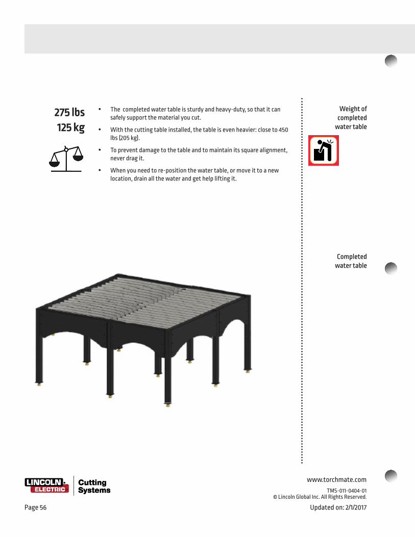
www.torchmate.com
TMS-011-0404-01 © Lincoln Global Inc. All Rights Reserved.
Page 56 Updated on: 2/1/2017
Completed water table
275 lbs125 kg
y The completed water table is sturdy and heavy-duty, so that it can safely support the material you cut.
y With the cutting table installed, the table is even heavier: close to 450 lbs (205 kg).
y To prevent damage to the table and to maintain its square alignment, never drag it.
y When you need to re-position the water table, or move it to a new location, drain all the water and get help lifting it.
Weight of completed
water table
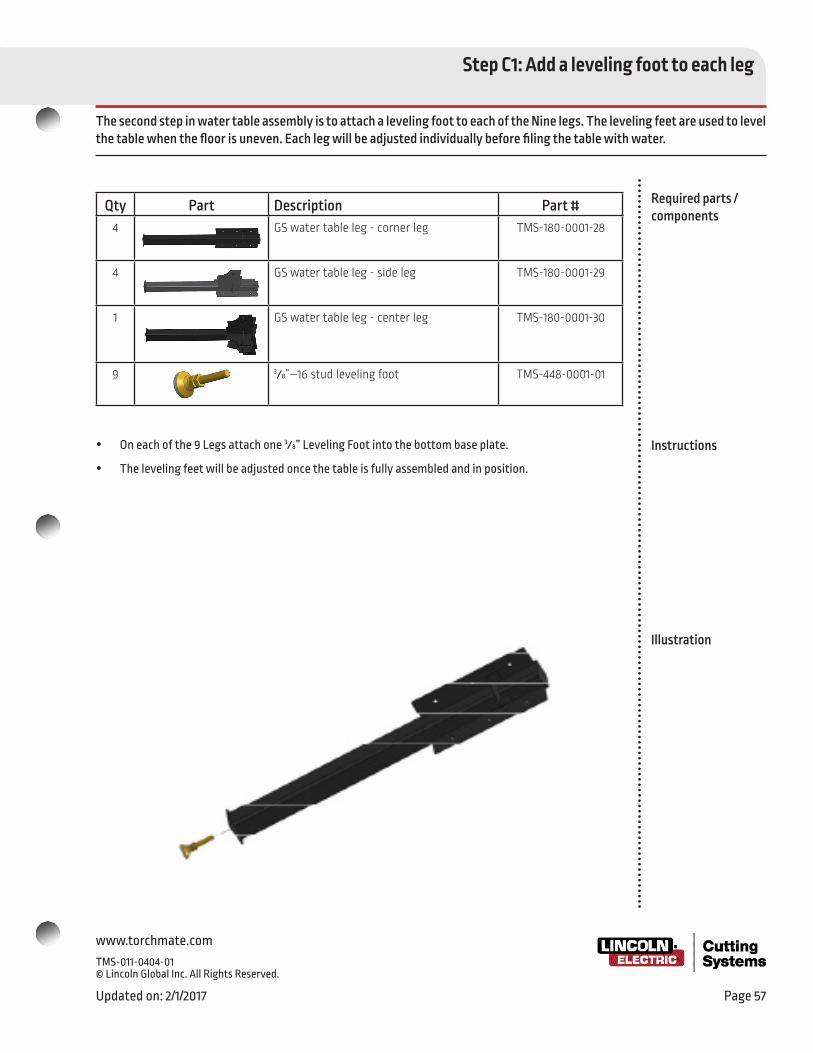
www.torchmate.com TMS-011-0404-01 © Lincoln Global Inc. All Rights Reserved.
Updated on: 2/1/2017 Page 57
Step C1: Add a leveling foot to each leg
The second step in water table assembly is to attach a leveling foot to each of the Nine legs. The leveling feet are used to level the table when the floor is uneven. Each leg will be adjusted individually before filing the table with water.
Required parts / components
Instructions
Illustration
y On each of the 9 Legs attach one 3⁄8” Leveling Foot into the bottom base plate.
y The leveling feet will be adjusted once the table is fully assembled and in position.
Qty Part Description Part #4 GS water table leg - corner leg TMS-180-0001-28
4 GS water table leg - side leg TMS-180-0001-29
1 GS water table leg - center leg TMS-180-0001-30
9 3⁄8”–16 stud leveling foot TMS-448-0001-01

www.torchmate.com
TMS-011-0404-01 © Lincoln Global Inc. All Rights Reserved.
Page 58 Updated on: 2/1/2017
Required parts / components
Instructions
Illustration
Qty Part Description Part #1 GS water table side 31" length TMS-180-0001-05
1 GS water table side 33.75" length TMS-180-0001-07
1 Assembled corner leg component From Step C2
2 Assembled side leg component From Step C2
12 Screw, BSCS, 5⁄16"–18 X 5⁄8" TMS-410-5016-10
Step C2: Attach legs to panels for first corner
In the third step, you attach the legs to both end panels. Because adjustments may be required later, you only loosely tighten the screws now.
y Attach one 33.375" side and 31" side to an assembled corner leg from Step C1 using six 5⁄16"–18 x 5⁄8" Button Head Cap Screws. All legs have nuts welded inside the bolt holes to ease the assembly process.
y Attach a Side Leg to the end of each panel, using 5⁄16"–18 x 5⁄8" Button Head Cap Screws The side panels are slotted to be adjusted once the cutting table is installed.
y Do not fully tighten the cap screws.

www.torchmate.com TMS-011-0404-01 © Lincoln Global Inc. All Rights Reserved.
Updated on: 2/1/2017 Page 59
Required parts / components
Instructions
Illustration
Step C3: Extend the sides with legs and side panels
In the fourth step, attach additional side panels to the legs and additional legs. Because adjustments may be required, you’ll only loosely tighten the screws.
Qty Part Description Part #1 Frame components–assembled From Step C2
1 GS water table side 25" length TMS-180-0001-09
1 GS water table side 22" length TMS-180-0001-08
2 Assembled corner leg From Step C1
12 Screw, BSCS, 5⁄16"–18 X 5⁄8" TMS-410-5016-10
y Continue with the water table frame assembly. Attach the 22" and 25" side panels to the side leg's as shown.
y Add the corner legs to each corner.
y Use 5⁄16"–18 X 5⁄8" button head cap screws.
y The side panels are slotted to be adjusted once the cutting table is attached.

www.torchmate.com
TMS-011-0404-01 © Lincoln Global Inc. All Rights Reserved.
Page 60 Updated on: 2/1/2017
Step C4: Complete the second and third corners
The 4x4 Growth Series water table frame, which holds the water pan, material support slats, and the cutting table. The fifth step attaches additional panels and legs to the frame.
Required parts / components
Instructions
Illustration
Qty Part Description Part #1 Frame components–assembled From Step C3
1 GS water table side 31" length TMS-180-0001-05
1 GS water table side 33.75" length TMS-180-0001-07
2 Side leg assemblies From Step C1
12 Screw, BSCS, 5⁄16"–18 X 5⁄8" TMS-410-5016-10
y Continue with the water table frame assembly. Attach remaining 31" and 33.75" length panels to the machine. Note they will be opposing their duplicate directly.
y Use 5⁄16"–18 X 5⁄8" button head cap screws.
y The side panels are slotted to be adjusted once the cutting table is attached.
y Do not fully tighten the cap screws.

www.torchmate.com TMS-011-0404-01 © Lincoln Global Inc. All Rights Reserved.
Updated on: 2/1/2017 Page 61
Step C5: Complete the fourth corner
In step six, you complete the assembly of the table frame. At this point, the cap screws attaching the side panels to the legs should not be fully tightened, but should be tight enough to provide the table with strength to hold the water pan and mate-rial slats. The frame will be squared and tightened after the water pan and cutting table are in place.
Required parts / components
Instructions
Illustration
Qty Part Description Part #1 Frame components–assembled From Step C4
1 GS water table side 25" length TMS-180-0001-09
1 GS water table side 22" length TMS-180-0001-08
1 Assembled corner leg From Step C1
12 Screw, BSCS, 5⁄16"–18 X 5⁄8" TMS-410-5016-10
y Complete the water table frame assembly. Attach the 22" and 25" side's to the side legs.
y Install the last Corner leg.
y Use 5⁄16"–18 X 5⁄8" button head cap screws.
y The side panels are slotted to be adjusted once the cutting table is attached.
y Do not fully tighten the cap screws.
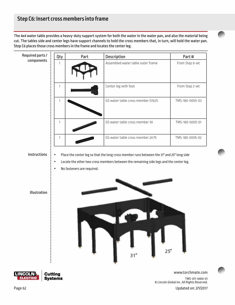
www.torchmate.com
TMS-011-0404-01 © Lincoln Global Inc. All Rights Reserved.
Page 62 Updated on: 2/1/2017
Required parts / components
Instructions
Illustration
Step C6: Insert cross members into frame
The 4x4 water table provides a heavy-duty support system for both the water in the water pan, and also the material being cut. The tables side and center legs have support channels to hold the cross members that, in turn, will hold the water pan. Step C6 places those cross members in the frame and locates the center leg.
Qty Part Description Part #1 Assembled water table outer frame From Step 6-wt
1 Center leg with foot From Step 2-wt
1 GS water table cross member 57.625 TMS-180-0005-03
1 GS water table cross member 30 TMS-180-0005-01
1 GS water table cross member 24.75 TMS-180-0005-02
y Place the center leg so that the long cross member runs between the 31" and 25" long side
y Locate the other two cross members between the remaining side legs and the center leg.
y No fasteners are required.

www.torchmate.com TMS-011-0404-01 © Lincoln Global Inc. All Rights Reserved.
Updated on: 2/1/2017 Page 63
Required parts / components
Instructions
Illustration
Step C7: Seal the water pans together
Assemble the water pans for the Torchmate Growth Series 4x4 CNC System water table by sealing the left (A) and right (B) sides together using a silicone sealant to prevent leaking.
Qty Part Description Part #1 GS water pan–A
(with drain outlet) TMS-180-0001-64
1 GS water pan–B TMS-180-0001-73
1 GS silicone sealant TMS-180-1001-01
22 Screw, Hex Cap, 5⁄16"–18 X 1/2" TMS-412-1116-08
22 Nut, Nylock, hex, 5⁄16"–18, steel, zinc-plated TMS-414-0201-16
y Apply a continuous, double bead of silicone sealant to the mating surfaces of the water pan beds along the edge to be sealed.
y Fasten the two water pan halves together with 5/16"-18 x 1/2" Hex screws and nylock nuts.
y Important: Leaving gaps in the sealant or forcing ALL of the sealant out of the joint by overtightening can cause leaks and require disassembly / reassembly.
y Trim off the excess sealant after it has thoroughly set.

www.torchmate.com
TMS-011-0404-01 © Lincoln Global Inc. All Rights Reserved.
Page 64 Updated on: 2/1/2017
Step C8: Install the drain valve and pan
In this step you install the drain valve in the water pan, and then set the pan into the table frame. The pan will be filled with water after the cutting table is added.
Qty Part Description Part #1 Assembled water table frame From
Step C6
1 Assembled water pan From Step C7
1 TFP-AR small table 3⁄4 plumbing (water release valve)
TMS-459-0010-01
1 PTFE thread-sealant tape (recommended) (separate purchase)
y Wrap PTFE tape around the valve threads and tighten the water release valve into the water pan.
y Get some help, as the pan is heavy. Carefully lower the pan into the table frame assembled in Step C6. The pan simply rests in the frame.
y You may connect a hose or other plumbing to the drain valve so that you may dispose of the table’s water appropriately, as necessary.
Install the drain valve
Lower the pan into the frame
Required parts / components
Instructions
Illustration

www.torchmate.com TMS-011-0404-01 © Lincoln Global Inc. All Rights Reserved.
Updated on: 2/1/2017 Page 65
Step C9: Add the material support slats
Qty Part Description Part #1 Assembled water table with pan From
Step C8
38 Material support slats 27 1/2" x 3" x 3⁄16"
(Obtain slats locally—not supplied)
y Cut 38 support slats from 3⁄16" thickness material. (This material is not supplied with your water table.) 38 slats at 3"tall x 27 1/2" long.
y Insert the slats into the slat support brackets in the pans. The offset in the Slat Support Holders is intentional, and not a manufacturing error! This offset creates a curve in the slats, which increases their rigidity, and prevents premature wear when cutting long lines in the width of the table.
y Over time, the cutting processes will consume the slats and you will flip them to use the new edge. After that side is consumed, replace these units.
The material to be cut will rest directly on the slats
The 4x4 water table provides a heavy-duty support system for the material being cut using slats that you supply (and replace from time to time) from local material. Placed on edge, with a slight curvature, the slats develop the strength required to provide durable, long lasting service. Sparks, debris, and smoke from the cutting process are minimized because of the open access to the water surface between the slats.
Required parts / components
Instructions
Illustration

www.torchmate.com
TMS-011-0404-01 © Lincoln Global Inc. All Rights Reserved.
Page 66 Updated on: 2/1/2017
Step C10: Secure cutting table to water table
Qty Part Description Part #1 Cutting table From Step A14
1 Water Table From Step C9
4 Screw, BSCS, 3/8"-16x1" TMS-410-0218-16
4 Washer, flat 3/8" washer, steel, zinc-plated TMS-413-0001-18
y Attach the cutting table to the water table’s legs. The legs have threaded holes. Use button-head cap-screws and flat washers.
y Check that the table is square and level. Adjust the leveling feet, as needed. Refer to Step 5 of the cutting table installation for the beginning steps of the squaring procedure. Repeat as needed.
y With the table square and level, fully tighten all screws.
y Fill the water pan with water and check for leaks.
Finally, in this step, you mount the cutting table onto the water table. Because the cutting table is heavy, work with another person to set the cutting table in place. After mounting it securely, check the table’s squareness by measurement and by high-speed jogging.
Required parts / components
Instructions
Illustration

www.torchmate.com TMS-011-0404-01 © Lincoln Global Inc. All Rights Reserved. 1170 Trademark Drive | Reno, NV 89521 | USA Phone: 775-673-2200 | 866-571-1066
Updated on: 2/1/2017 Page 67
Deploying the Plasma Cutter

www.torchmate.com
TMS-011-0404-01 © Lincoln Global Inc. All Rights Reserved.
Page 68 Updated on: 2/1/2017
y The Plate Marker option is a CNC controlled, pneumatically operated tool that strikes the plate with a hardened tip. Each strike by the tool upon the plate produces a small crater or indent, and by producing a series or array of these, you can create text, outline, and fill effects on many surfaces.
Intelligent AVHC for plasma
y The Growth Series CNC tables with Accumove2 Technology come with an advanced system for achieving high quality cutting, with intelligent Arc Voltage Height Control.
y The details of the Intelligent AVHC will be discussed in the next section.
Other tooling op-tions
Cutting tools for Growth Series™ tables
The Growth Series tables with Accumove 2 Technology include an AVHC control and Z-axis lifter station for plasma cutting. The steps that follow illustrate the mounting and wiring for a plasma cutter and AVHC. There are two optional tools for your Growth Series table, a Pneumatic Plate Marking attachment, and Laser Crosshair assembly.
Intelligent AVHC components
y Pneumatic Plate Marking Attachment.
y Laser Crosshair assembly.

www.torchmate.com TMS-011-0404-01 © Lincoln Global Inc. All Rights Reserved.
Updated on: 2/1/2017 Page 69
AVHC components y The AVHC system consists of:
y A motor driven Z-axis that raises and lowers the torch under control of the Accumove 2
y An ohmic cap sensor for finding the “zero height” of the torch prior to starting an arc
y A VFC (Voltage Frequency Converter) electronics box that measures the arc voltage when the arc has started and sends a signal to the Accumove 2 indicating that voltage.
y A Magnetic Breakaway sensor to protect the torch from collisions with tipped up parts.
y Cables to connect the components to the Accumove 2, the sensors, and the plasma power supply.
y Plasma cutters are designed to produce a constant electrical current in the plasma arc. If the distance between the torch and the workpiece is longer, a higher voltage must be used to maintain the current than if the distance is shorter (because of the riesistance of the air).
y Cut bevel (angle) is created when the arc length is either too long or too short or the torch travel speed is too fast or too slow.
y The optimum arc length for a given material type, thickness, and amperage (current), will produce the best quality. The cut charts supplied with the plasma cutter give the preferred starting point for determining the optimum arc length.
y Using sophisticated computations, the Accumove 2 adjusts the speed and torch height at various points along curves and at corners to compensate for the changes in effective arc length that happen in those parts of the cuts, to achieve greater quality and reliability.
y Before an arc is initiated by the Accumove, the AVHC must raise the torch tip to the recommended pierce height (typically some distance greater than the established cutting arc length). Because of the non-uniformity of the material being cut, this pierce height is measured by using an ohmic cap to sense the zero distance.
y To determine the position of the material, the AVHC lowers the torch until the torch cap just touches the material. A an electrical connection between the VFC and the material “ground” lets the VFC know when the cap touches the material and completes it’s circuit.
y Following this, the Accumove 2 raises the torch to the level of the initial pierce height. This height is also found in the plasma cutter’s cut charts.
Features of the Accumove 2 AVHC
The Growth Series tables with Accumove 2 Technology includes an intelligent AVHC system to produce cuts with a high qual-ity level. Other than good quality consumables, the primary factor governing cut quality is the length of the plasma arc. Standard arc lengths are published for each plasma cutter and the AVHC system uses the arc voltage measuring technique to control the height of the torch above the material being cut.
What is arc voltage?
Ohmic cap sensing

www.torchmate.com
TMS-011-0404-01 © Lincoln Global Inc. All Rights Reserved.
Page 70 Updated on: 2/1/2017
What is the VFC?
Magnetic breakaway
y The VFC box, placed close to the plasma power unit to minimize EMI interference, measures the voltage the unit is producing to achieve it’s set amperage, The VFC transforms the voltage to a signal that has greater noise-immunity and sends it to the Accumove 2. The Accumove 2 then sends signals to the Z-axis motor to adjust the torch height.
y Because of the industrial environment of the typical CNC plasma cutting table, electronic noise, especially Electromagnetic Interference (EMI) can disrupt the operation of the controllers, and other electronics leading to potential issues. The VFC unit has been designed to reduce the effect of any EMI present in your shop environment.
y For more information on what you can do to reduce EMI effects and ensure the highest reliability for your Torchmate CNC system, please search the Torchmate.com web site for “EMI Reduction.”or look on the Torchmate / Lincoln Electric Cutting Systems USB Flash Drive supplied with your system.
y A magnetic breakaway is an available option for your AVHC torch holder. The torch is held securely to the Z-axis carriage on the lifter station by magnetic force. If the torch encounters an obstacle and collides with it, rather than breaking the torch body, the collision overcomes the magnetic force and the torch body breaks away from its mounting.
y In addition, the magnetic breakaway signals the Accumove 2 to stop all table movements and turn off the plasma power supplies cutting arc.
AVHC, VFC, and cables

www.torchmate.com TMS-011-0404-01 © Lincoln Global Inc. All Rights Reserved.
Updated on: 2/1/2017 Page 71
Step D1: Attach the tool mounting bracket to the tool mounting pate
Use of the 90 degree tool mounting plate allows the plasma torch to achieve full travel in Y-axis direction. If this full travel is not required, the use of the right-angle bracket may be omitted. Approximately 1.5 inches of travel overall in the Y-axis direc-tion is sacrificed by attaching the height control lifter station directly to the Primary Tool Mounting plate.
Qty Part Description Part #1 Laptop or PC, Accumove2, and wired CNC
Cutting tableFrom Step B10
1 Primary Tool Mounting plate TMS-180-0001-66
1 90 degree Tool Mounting plate TMS-180-0150-03
2 Screw, BSCS, 5/16-18 X 1”, hex drive TMS-410-0016-12
4 Screw, BSCS, 5/16-24 x 3/4” TMS-410-0017-20
2 Nut, Nylock, 5/16”-18, zinc-plated steel TMS-414-0701-16
4 Screw, BSCS, 5/16-18 X 5/8” TMS-410-5016-10
Required parts / components

www.torchmate.com
TMS-011-0404-01 © Lincoln Global Inc. All Rights Reserved.
Page 72 Updated on: 2/1/2017
Illustration
How to install the 90 degree tool mount-
ing plate
y To mount the 90 degree tool mounting bracket to the plate follow these steps:
y Bolt the 90 degree tool mounting plate to the Primary Tool Mounting plate as shown using two 5/16”-18 x 3/4” Hex Head and two 5/16-18 Nylock Nuts
y Attach the Primary Tool Mounting plate to the gantry using the 5/16”-24 x 3/4” Socket Head Cap screws. Use the highlighted 4 bolt holes, regardless if the 90 degree tool mounting plate is utilized, and attach the unit to the gantry’s four standoffs.
y Note: If a plate marker is being attached, do not attach the plate marker until after this step!
Attach the PrimaryTool Mounting Plate
to the Gantry
Step D1: Attach the Primary and 90 degree Tool Mounting Plates

www.torchmate.com TMS-011-0404-01 © Lincoln Global Inc. All Rights Reserved.
Updated on: 2/1/2017 Page 73
y Connect the Lifter Station to the 90 degree Tool Mounting Plate using 4, 5/16”-18x5/8” Flanged Button Head Cap Screws, using 4 of the bottom-most attachment holes in the lifter station.
y Note that the bottom of the Lifter Station is mounted even to, or higher than the bottom of the bracket. This is essential to ensure the machine achieves full motion.
There are six threaded mounting holes in a rectangular array on the back of the Z-axis lifter. Use the four holes that are closest to the end of the Z-axis lifter to mount it to the tool mounting bracket or tool mounting plate.
Step D2: Mount the AVHC lifter

www.torchmate.com
TMS-011-0404-01 © Lincoln Global Inc. All Rights Reserved.
Page 74 Updated on: 2/1/2017
Step D3: Mount the Magnetic Breakaway Assembly
Qty Part Description Part #1 Assembled Components From Step D3
1 Magnetic Breakaway Assembly TMS-101-5000-11
4 M6x1.00mm x 25mm SHCS TMS-429-0011-01
y Attach the Magnetic Breakaway Assembly to the Lifter Station using the provided M6x1.00x25mm Socket Head Cap screws.
y Note that the magnetic breakaway plate may obscure these mounting holes, and may need to be detached from the backing plate to access all 4 screw locations.
1 2
34
1 2
34

www.torchmate.com TMS-011-0404-01 © Lincoln Global Inc. All Rights Reserved.
Updated on: 2/1/2017 Page 75
y The OK to Move wires, and the raw arc voltage wires can be completed by wire splicing. There are several methods that are suitable. Be sure all connections do not leave an exposed wire, even if the connection is unused
Step D4: Prepare the plasma cutter
The plasma cutter works with CNC systems like Accumove 2 because it can produce signals indicating its state for the CNC system, and respond to signals when the CNC system tells it to start and stop cutting. All these signals go through the CNC interface cable on Lincoln Electric plasma cutters. Other plasma cutters require additional wiring. These cables must be pre-pared for connection to the Accumove2 and VFC. Other preparation involves power and air / gas supplies
Qty Part Description Part #1 Plasma cutter power supply unit Purchased
separately
1 CNC Interface cable Supplied with plasma cutter
Required parts / components
Making wire splices to the CNC cable and other cables
y 20 gauge twist-on wire nut connectors (typically gray or blue)
y Crimp-on butt splice connectors (be sure to use the proper size connector and the proper crimping tool)
y Solder joints with shrink wrap
Wire nut
Butt splice
Solder joint
y If the CNC cable ends have lug connectors, clip these connectors off and remove about 1/4” of insulation for use in making your connections.
y The quality of the power and compressed air / gas you provide for your plasma power unit has a direct and immediate effect on the quality of the cuts you make.
y Check the documentation for your plasma power unit model and verify that you have met the requirements for power and compressed gas / air.
y If you have an air compressor, remember to follow the recommended maintenance for ensuring that the air is dry and clean.
y Make sure the voltage and amperage of your electrical service are stable and within the required specifications. Consult with qualified electrical personnel or your power service company.
Verify power and compressed gas/air availability and quality

www.torchmate.com
TMS-011-0404-01 © Lincoln Global Inc. All Rights Reserved.
Page 76 Updated on: 2/1/2017
Pinouts on the Lincoln Electric plas-
ma power unit
The connector may be mounted at a very different angle, so be sure to check the markings on the connector before making any wiring changes that require identifying the cable letters
CNC interface cables for other types of
plasma power units
Non-Lincoln Electric CNC interface cables will not contain Raw Arc Voltage wires. These will be added as a separate cable either at the Torchmate factory, or, if your plasma cutter was not part of your system order, by your shop during
assembly. Call Torchmate Technical Support for specific instructions for your model plasma cutter.
y The Lincoln Electric plasma power units have a specially designed CNC cable that directly supports the use of raw arc voltage for controlling the torch height. This cable simplifies wiring for the Accumove 2.
y For other plasma power units, the raw arc voltage signal is frequently not available on the CNC interface cable.
y If you purchased one of these units with your Torchmate Growth Series CNC System, the factory will have installed the necessary raw arc voltage cable before shipping, and will be a two conductor Black and Red wire leaving the power supply seperately.
y If your plasma power unit was not part of the package, you will have to install the cable for the raw arc voltage in order to complete the setup. Call Torchmate Technical Support and give them the make and model of your plasma power unit. They will provide the information you will need
Differences between plasma power units
Toll Free: 1-866-571-1066
International: 775-673-2200
Fax: 775-673-2206
Email: [email protected]
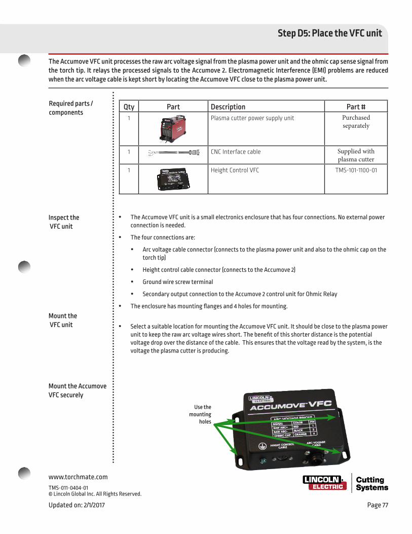
www.torchmate.com TMS-011-0404-01 © Lincoln Global Inc. All Rights Reserved.
Updated on: 2/1/2017 Page 77
Step D5: Place the VFC unit
The Accumove VFC unit processes the raw arc voltage signal from the plasma power unit and the ohmic cap sense signal from the torch tip. It relays the processed signals to the Accumove 2. Electromagnetic Interference (EMI) problems are reduced when the arc voltage cable is kept short by locating the Accumove VFC close to the plasma power unit.
y The Accumove VFC unit is a small electronics enclosure that has four connections. No external power connection is needed.
y The four connections are:
y Arc voltage cable connector (connects to the plasma power unit and also to the ohmic cap on the torch tip)
y Height control cable connector (connects to the Accumove 2)
y Ground wire screw terminal
y Secondary output connection to the Accumove 2 control unit for Ohmic Relay
y The enclosure has mounting flanges and 4 holes for mounting.
y Select a suitable location for mounting the Accumove VFC unit. It should be close to the plasma power unit to keep the raw arc voltage wires short. The benefit of this shorter distance is the potential voltage drop over the distance of the cable. This ensures that the voltage read by the system, is the voltage the plasma cutter is producing.
Inspect the VFC unit
Mount the VFC unit
Use the mounting
holes
Qty Part Description Part #1 Plasma cutter power supply unit Purchased
separately
1 CNC Interface cable Supplied with plasma cutter
1 Height Control VFC TMS-101-1100-01
Required parts / components
Mount the Accumove VFC securely

www.torchmate.com
TMS-011-0404-01 © Lincoln Global Inc. All Rights Reserved.
Page 78 Updated on: 2/1/2017
Step D6: Connect the VFC unit
The Accumove VFC unit processes the raw arc voltage signal from the plasma power unit and the ohmic cap sense signal from the torch tip. It relays the processed signals to the Accumove 2.
Qty Part Description Part #1 Mounted Accumove VFC From Step D4
1
Arc Voltage/Ohmic Cable TMS-101-1109-01
1 Height control cable TMS-103-5000-01
1 12 Awg Stranded Chassis ground wire From your toolbox
1 Ohmic Cap (torch consumable stack)
Depends on plasma power unit
1 Trimmed CNC Interface cable or raw arc voltage cable
Depends on plasma power unit
Required parts / components
y The arc voltage / ohmic cable is keyed, and can only be inserted one way. Push the connector into the Accumove VFC port and use the threaded ring to secure it.
y The height control cable is keyed. Push the connector into it Accumove VFC Port.
y Connect a ground wire to the green screw terminal. Run the ground wire to Star Ground of the table (See section D7, Grounding).
y Uncoil the long orange wire from the arc voltage cable connector and run this to the table, through the cable carriers to the torch, and to the ohmic retaining cap clip.
y Splice the red and black wires from the arc voltage cable to the arc voltage wires in the Lincoln Electric CNC interface cable. Red is Positive, black is Negative on the VFC box.
y If a non-Lincoln Electric plasma power unit was supplied with your CNC system, splice to the installed raw arc voltage cable. It will be a separate wire from the CNC interface cable. Observe the polarity (red is positive, black is negative).
y Consult with Torchmate Technical Support if your plasma power unit was obtained from a different source. You will receive instructions for your make and model of plasma power unit for connecting your own raw arc voltage cable. Splice this cable to the red and black wires of from the Accumove VFC observing the polarity.
y IMPORTANT NOTE: Observe the polarity of the arc voltage when making the splice.
y Connect the height control cable to the keyed socket on the Accumove 2
Attach the Accumove VFC cables
Splice the cables

www.torchmate.com TMS-011-0404-01 © Lincoln Global Inc. All Rights Reserved.
Updated on: 2/1/2017 Page 79
Run the height control cable and secondary output cablefrom the VFC to the Accumove 2 ports shown below
Splice the red and black wires to the plasma power unit’s raw arc voltage wires. Be sure to observe polarity.
Run the orange wire to the ohmic sensing cap at the end of the torch. The orange wire is pre-terminated with a female spade connector
Run 12 awg stranded ground wire from the VFC to the machine’s Star Ground
Splice and connect the cables

www.torchmate.com
TMS-011-0404-01 © Lincoln Global Inc. All Rights Reserved.
Page 80 Updated on: 2/1/2017
Run and connect the wires
Step D7: Wiring for Lincoln Electric plasma cutters
Wiring for Lincoln Electric plasma cutters is simplified because all connections to the plasma cutter are contained in the CNC cable. The additional wiring steps are based on the diagram on the following page.
y Run the torch and work leads from the table to the plasma power unit, then make the CNC cable connections to the VFC and Accumove 2.
y Connect the K and M Arc Start wires to the #1 output terminals on the Accumove2. Use the Terminal block 2 Position to complete this connection. This connection is NOT polarity specific.
y Connect the J and I Arc Initiated wires to the the Input Cable. These wires will connect to #1 (Red) and COM (black). The other input wires are unused and should be trimmed back, and tied away as to not contact a ground point. This connection is NOT polarity specific.
y Run the height control cable from the VFC to the Accumove.the wiring components for the control of the torch and control of the AVHC unit. Both ends of this cable are the same. It’s best to position the VFC close to the plasma power unit and well away from the Accumove2 in order to minimize EMI problems.
y Run the Ohmic cap cable from the torch lead the VFC using the orange wire.
y Run the wire from the magnetic breakaway sensor to the Accumove 2 Breakaway port.
Qty Part Description Part #1
Height Control VFC, ACCUMOVE From Step D5
1 Terminal Block Plug 2POS STR 5.08MM TMS-403-0076-01
1 Input Cable, ACCUMOVE, TORCHMATE PRO TMS-103-5000-03
4 20 gauge twist-on wire nut connectors or Butt connectors
From your toolkit not supplied
Required parts / components

www.torchmate.com TMS-011-0404-01 © Lincoln Global Inc. All Rights Reserved.
Updated on: 2/1/2017 Page 81
Use this wiring diagram for Lincoln Electric plasma cutters

www.torchmate.com
TMS-011-0404-01 © Lincoln Global Inc. All Rights Reserved.
Page 82 Updated on: 2/1/2017
Run and connect the wires
Step D8: Wiring for non-Lincoln Electric plasma cutters
Wiring for Lincoln Electric plasma cutters is simplified because all connections to the plasma cutter are contained in the CNC cable. The additional wiring steps are based on the diagram on the following page.
y Run the torch and work leads from the table to the plasma power unit, then make the CNC cable connections to the VFC and Accumove2.
y Connect the Red and Black pair of wires for OK to Move to the Accumove Input cable. Red connects to Red #1, and Black connects to the Black COM wire.
y Connect the Green and Black pair of wires to the #1 output terminals on the Accumove 2. Use the Terminal block provided, this connection is NOT polarity specific.
y Connect the Raw Arc Voltage points from your plasma cutter to the Red and Black wire pair coming from the VFC. Red is positive, and black is negative.
y Refer to your plasma power unit manual for the location of the Raw Arc Voltage signal.
y Contact Torchmate Technical Support for assistance with this step. Provide the brand and model number of your plasma power unit and ask for instructions on connecting your VFC to the Raw Arc Voltage. Call Monday through Friday from 7 AM to 4 PM (07:00 to 16:00), Pacific Time Zone:
Toll Free: 1-866-571-1066, International: 775-673-2200, Fax: 775-673-2206, Email: [email protected]
y Run the Ohmic cap cable from the torch lead the VFC using the orange wire.
y Run the wire from the magnetic breakaway sensor to the Accumove 2 Breakaway port.
Qty Part Description Part #1
Height Control VFC, ACCUMOVE TMS-101-1100-01
1 Height Control Cable, ACCUMOVE TMS-103-5000-01
1 Arc Voltage Ohmic Sense Cable, Height Control
TMS-101-1109-01
1 Terminal Block Plug 2POS STR 5.08MM TMS-403-0076-01
1 Input Cable TMS-103-5000-03
Required parts / components

www.torchmate.com TMS-011-0404-01 © Lincoln Global Inc. All Rights Reserved.
Updated on: 2/1/2017 Page 83
Use this wiring diagram for plasma cutters not made by Lincoln Electric
Step D8: Wiring for non-Lincoln Electric plasma cutters

www.torchmate.com
TMS-011-0404-01 © Lincoln Global Inc. All Rights Reserved.
Page 84 Updated on: 2/1/2017
Step D9: Machine Grounding
Grounding your Lincoln Electric CNC machine is very important. This can prevent EMI noise from causing issues with electri-cal components both related and unrelated to the machine, reduce the electrical shock hazard at the machine, and ensure that the Ohmic Sensing circuit operates trouble free.
y Proper grounding must be provided to ensure personnel safety and to suppress high frequency EMI noise. The foundation of good grounding is an effective earth ground rod. A star ground point on the machine frame usually connects to the dedicated ground rod with a short, heavy conductor. Lincoln Electric recommends that the gauge conductor matches that if the Plasma Cutter ground clamp. 12 AWG Stranded wires radiate out from this Star Ground to each component of the system, establishing a central grounding point. A simple copper clad steel rod can be driven into the ground to create a Grounding Rod; however, the rod must be driven into the ground deep enough such that it comes into contact with dense, moist earth, to ensure a proper earth ground. Dry sandy earth does not generate a good ground, and requires either a larger diameter rod, or more depth. Consult your local electrician for installation of this ground rod.
y Not all Torchmate machines come with a dedicated star ground point. This must be installed/connected by the end user at the time of installation. The machine frame that has electrical continuity to the metal Slat Supports is ideal. The connecting point must be free of paint, powdercoat, or rusty connections.
y See the below reference diagram as a general guide.
y For more information on EMI and Grounding please visit http://torchmate.com/white-papers/EMI-Reduction