tor for electrification of five (5) isolated rural areas ... · and their level of education is of...
TRANSCRIPT

TOR for Electrification of Five (5) Isolated Rural Areas by use of Photovoltaic Systems (PV) in the
Provinces of Tete and Manica
Junho 2007

1
CONTENTS
A. DESCRIPTION OF PROJECTS, GOODS AND SERVICES TO BE SUPPLIED ............ 3
B. SCOPE OF WORK .............................................................................................................. 5 B.1 Identification of Categories of Users ................................................................................. 5 B.2 Installation of Solar Photovoltaic Systems......................................................................... 5
B.2.1 Systems description .................................................................................................. 5 B.2.2 Documentation and training ...................................................................................... 7 B.2.3 Delivery schedule ..................................................................................................... 7
B.3 After-sales services for solar photovoltaic systems ............................................................ 7 B.3.1 System warranty ....................................................................................................... 7 B.3.2 Maintenance ............................................................................................................. 8
C.TECHNICAL SPECIFICATIONS AND STANDARDS ...................................................... 9 C.1 Load assessment and sizing .............................................................................................. 9 C.2 Project requirements ........................................................................................................ 9
C.2.1 Applicable standards ............................................................................................... 10 C.2.2 Photovoltaic modules ......................................................................................... 10 C.2.3 Batteries ............................................................................................................. 10 C.2.4 Solar charge controllers .......................................................................................... 11 C.2.5 Inverters ................................................................................................................. 11 C.2.6 Interior luminaires .................................................................................................. 11 C.2.7 Exterior luminaires ................................................................................................. 11 C.2.8 Streetlight ............................................................................................................... 12 C.2.9 Portable lanterns ..................................................................................................... 12 C.2.10 Solar Refrigerators for Conservation of Vaccines .................................................. 13 C.2.11 Solar Fridges for Shops ......................................................................................... 13 C.2.12 Photovoltaic water pumping systems ..................................................................... 14
C.3 Project Specific Technical Specifications ........................................................................ 15 C.3.1 KIT A: Social households (solar lanterns)............................................................... 15 C.3.2 KIT B: Non social household .................................................................................. 15 C.3.3 KIT C: Shop owners equipped with fridges ............................................................. 16 C.3.4 KIT D: Water pumping system................................................................................ 16 C.3.5 KIT E: School......................................................................................................... 17 C.3.6 KIT F: Health centre ............................................................................................... 18 C.3.7 KIT G: Administrative and Police posts .................................................................. 18 C.3.8 KIT H: Public lighting system ................................................................................. 18 C.3.9 Example of a Bill of Quantities ............................................................................... 20 C.3.10 Code of practice for installation ............................................................................. 22 C.3.11 Spares ................................................................................................................... 24 C.3.12 Training code ........................................................................................................ 26 C.3.12 Documentation to be provided ............................................................................... 26
C.4 Technical specifications: Maintenance ........................................................................... 27 C.4.1 Routine maintenance............................................................................................... 27 C.4.2 Breakdown repair maintenance service .................................................................... 28 C.4.3 Maintenance log sheets ........................................................................................... 28
D: GENERAL REQUIREMENTS AND SPECIFICATIONS FOR SOLAR PHOTOVOLTAIC HOME SYSTEMS .................................................................................. 34
D.1 Solar Home System Hardware Description ..................................................................... 34 D.2 Certification Requirements ............................................................................................. 35 D.3 Recommended Best Practices ......................................................................................... 35
D.3.1 Photovoltaic Module Installation ............................................................................. 35 D.3.2 Circuit Protection and Charge Controls ................................................................... 37 D.3.3 System Monitoring ................................................................................................. 37 D.3.4 Batteries ................................................................................................................. 38 D.3.5 DC/AC Inverters .................................................................................................... 39

2
D.3.6 Equipment Enclosure .............................................................................................. 39 D.3.7 Wiring .................................................................................................................... 39
D.4 Documentation .............................................................................................................. 40 D.4.1 Users Manual ......................................................................................................... 40 D.4.2 Technicians Manual ................................................................................................ 41
D.5 Packaging and Delivery ................................................................................................. 42

3
A. DESCRIPTION OF PROJECTS, GOODS AND SERVICES TO BE SUPPLIED Five rural areas are to be electrified in the provinces of Tete and Manica. Both provinces are located at the central part of the country. Tete, with 12 districts, has an area of about 100,724 Km2 and a population of approximately 1.4 million inhabitants, being Tete City the capital of the province. The province of Manica, with 8 districts, has an area of 61,661 km2 and a population of 1.2 million inhabitants, being Chimoio the capital of the province. Annex 1 shows the map of Mozambique, with indication of the two provinces. Annexes 2 and 3 represent the road maps of Manica and Tete, indicating also the sites where the projects will be implemented. According to the road maps, the access from the provincial headquarters to the districts headquarters is in general through roads with asphalt, while from the district headquarters to the “postos administrativos” the access is made through secondary roads in general. Thus four wheel drive vehicles are essential to reach the “postos administrativos”. Annex 4 shows a table with distances from the provincial headquarters to the districts and from these to the “postos administrativos”. In annex 5 environmental characteristics of the two provinces are presented, namely the solar radiation, the ambient temperature and the rainfall. Accommodation with electricity and water is available in all district headquarters, as all of them are electrified either through electricity from the national grid or through diesel gensets. The “postos administrativos” are in process of electrification. Some are connected to the national grid, others have diesel gensets. Very recently a process of electrification using photovoltaic systems has been started by FUNAE. In this project the rural areas to be electrified by use of photovoltaic systems in both provinces are the “postos administrativos” of Malowera (district of Maravia), Vila Muladzi (district of Chifunde), Muze (district of Zumbo) all in Tete province and Mavonde (district of Manica) and Mungari (district of Guro) in Manica province. The electrification envisaged in this project will cover (i) administrative buildings, including police posts, (ii) schools and health centres, (iii) shops and (iv) residences. In general the residences are made of local materials, while the other buildings mentioned use conventional construction, based on cement. Apart from electrification, water pumping systems using photovoltaic solar energy will be installed in available boreholes in each of the “postos administrativos” mentioned. In its strategy of projects implementation, FUNAE involves the local authorities and the communities. The local communities are also responsible to identify people who will act as local operators, who are supposed to have some general technical and organizational background. In the process of implementation of the project they are then trained in specific issues related to the project. In the case of this project such people have been already identified and their level of education is of at least 7th grade. FUNAE has already identified all the potential beneficiaries of the systems to be installed. The contractor will be responsible for installation of the systems and training of the local operators. All systems must be installed and commissioned within 6 months of contract award.

4
In this project FUNAE, as contracting agency, is responsible for facilitation of the whole process, provision of different types of information, coordination of the activities and contacts with the local authorities and communities, identification of sites for installation of the systems and collection of fees, among others.

5
B. SCOPE OF WORK
This work is to procure, install and commission all solar photovoltaic systems and end use appliances in schools, health centres, administrative offices, police posts, shops and residences, in five “postos administrativos” of the provinces of Tete and Manica, during a period of six months. Training of the local operators is also part of the work. A one-year system warranty shall be provided for each system installed.
B.1 Identification of Categories of Users For this purpose 8 categories of users were defined, corresponding each one to a specific kit. Such categories and the respective kits were defined as follows:
1. Private facilities
(i) Category of social household – KIT A; (ii) Category of non social households – KIT B; (iii) Category of shop owners equipped with fridges – KIT C. 2. Public facilities
(iv) Category of water pumping systems – KIT D; (v) Category of schools – KIT E; (vi) Category of health centres - KIT F; (vii) Category of administrative and police posts – KIT G; (viii) Category of public lighting – KIT H.
For organizational purposes two lots were defined in this work, corresponding Lot 1 to activities in the province of Tete and Lot 2 to activities in the province of Manica. Table 1 below summarizes the information in these two lots. Table 1: Identification of lots and summary data
LOT PROVINCE DISTRICT ”POSTO ADMINISTRATIVO”
KIT A
KIT B
KIT C
KIT D
KIT E
KIT F
KIT G
KIT H
Lot 1 Tete Zumbo Muze 4 50 2 1 1 2 2 10
Chifunde Vila Mualadzi 8 30 1 0 1 1 2 10 Maravia Malowera 10 35 2 0 1 1 2 10
Lot 2 Manica
Manica Mavonde 14 24 2 1 1 1 2 10
Guro Mungari 21 28 2 1 1 1 2 10
B.2 Installation of Solar Photovoltaic Systems
B.2.1 Systems description Technical specifications are provided for solar electricity systems for the following applications in the private and public facilities of the two provinces:

6
Social households – lighting by solar lanterns; Non-social households/small shop owners - lighting (indoors and
outdoors) and outlet for TV/radio; Shop owners – lighting (indoors and outdoors) and outlets for
TV/radio and fridge; Water pumping systems – for community water supply; Schools energy services – lighting (indoors and outdoors) and outlets
for audio visual equipment like TV and computing; Health centres energy services – lighting (indoors and outdoors),
outlet for TV/radio and for vaccine fridge, including the suplly of the solar refrigerator;
Administrative and police posts energy services – lighting (indoors and outdoors) and outlet for TV/radio;
Public lighting energy services – street lights. The recommended system configuration for the identified solar photovoltaic packages in the project is 12 V DC and 220-240 V AC electricity for energy efficient appliances, such as TV/radio, computers and videos. Exception to this is the PV water pumping system, which has its own characteristics. It is to note that the supply of televisions, radios, computers and videos is not the responsibility of the contractor. The systems are described in table 2 below. Table 2: Systems description KIT Application Description
A Social household 12 V DC lanterns, for lighting and small appliances (radio, cell phone charger).
B Non social household
12 V DC supply: a total of approximately 132 Wh/day for lighting (indoors and outdoors); 220 V AC supply: a total of approximately 400 Wh/day to supply AC loads such as TV/Video or Radio.
C Shop owners equipped with fridges
12 V DC supply: a total of approximately 132 Wh/day for lighting and 720 Wh/day for fridge (refrigerator/freezer); 220 V AC supply: a total of approximately 400 Wh/day for outlets for TV/Video or radio.
D Water pumping systems N/A
E School
12 V DC supply: a total of approximately 990 Wh/day for lighting (indoors and outdoors); 220 V AC supply: a total of approximately 1000 Wh/day for outlet for audio/visual equipment and computing.
F Health Centres
12 V DC supply: a total of 720 Wh/day for conservation of vaccines and a total of 440 Wh/day for lighting (indoors and outdoors) ; 220V AC supply: a total of 400Wh/day for appliances like TV/video or radio.

7
G Police or administrative posts
12 V DC supply: a total of approximately 99 Wh/day for lighting (indoors and outdoor), and 220 V AC supply: a total of approximately 300 Wh/day to supply AC loads such as TV/Video or Radio.
H Public lighting 12 V DC system; 216 Wh/day or 19.2 Ah/day @ 12 V DC for lighting using a 11W pole mounted luminaire.
B.2.2 Documentation and training Documentation, as set out in the Technical Specifications, shall be provided at each system installed. User training, as set out in the Technical Specifications, shall be provided at each system installed.
B.2.3 Delivery schedule All systems identified above must be delivered, installed and commissioned within six (6) months of contract effectiveness.
B.3 After-sales services for solar photovoltaic systems The project contractor will guarantee the provision of spare parts during the first year of operation of the project. After that period the local operator contracted by FUNAE will maintain at least one sales and service centre in the project area to serve the support needs of the public facilities as well as those of sales to households and other private sector facilities.
B.3.1 System warranty A one-year system warranty shall be provided for each system installed. This warranty will ensure the availability of the energy services provided by the systems supplied under this bid. The system warranty shall apply for the solar photovoltaic energy system, including light fittings and other end-use appliances supplied under this contract, but not the appliances supplied by other entities and used on the system. The following criteria will be used to determine the availability of the energy services:
The number of systems breakdowns over one (1) year should be less than eight per cent (8%) of the number of the systems installed.
Should any fault arise, this warranty will provide for the necessary maintenance or component replacement in order for full functionality to be restored within ten (10) working days.

8
If lightning protection is installed in accordance with Section C.3.10, then lightning damage will be considered force majeure and will not be covered by system warranty. Theft and vandalism will also be considered force majeure. In addition of one year warranty for the whole system the following warranties shall be issued by the Contractor:
10 years for PV modules; 3 years for batteries; 2 years for the charge controllers and inverters; 2 years for all other parts of the PV system, including all DC
appliances.
B.3.2 Maintenance Over the course of the one-year warranty period, a routine maintenance regime will be implemented according to the technical specifications provided in Section C.4.1. The routine maintenance will be undertaken at each and every solar PV system installed in accordance with this scope of work. A break-down repair service shall be available to users in accordance with Section C.4.2.

9
C.TECHNICAL SPECIFICATIONS AND STANDARDS
C.1 Load assessment and sizing Load assessment was undertaken in all places where the PV systems will be installed. In accordance with that, the minimum array, battery, charge controller and inverter sizes in each category, excluding the pumping systems, are summarized below.
Table 3: Required minimum sizes of array, battery, charge controller and inverter in each category
As far as photovoltaic water pumping systems is concerned, the borehole characteristics in the three selected sites are presented in table 4 below. Table 4: Characteristics of the boreholes in the selected sites
Site Depth of the borehole (m)
Yield (m3/h)
Water static level (m)
Water dynamic level (m)
Inner diameter of the borehole (inches)
Muze 52.5 2.4 13.0 17.0 4
Mungari 23.0 4.5 3.0 16.0 4
Mavonde 13.0 1.5 3.0 8.5 4
C.2 Project requirements These general specifications provide the overall specifications for components and materials supplied within the bid. Details regarding the solar PV systems are set out in Section C3. The rural power project specifications for solar home systems are set out in part D.
System Array (Wp)
Battery (Ah)@C20xV
Charge controller
(A)
Inverter (W)
Social household (A) 10 7.2 x 12 -- n/a Non social household (B) 170 180 x 12 20 150 Shop owners equipped with fridges (C) 400 420 x 12 25 150 Water pumping systems (D) n/a n/a n/a n/a School (E) 630 670 x 12 40 300 Health Centers (F) 500 520 x 12 40 150 Police and administrative posts (G) 130 140 x 12 10 150 Public lighting system (H) 80 80 x 12 5 n/a

10
C.2.1 Applicable standards In general, products which bear the Photovoltaic Global Approval Program (PV GAP) Mark or Seal or certified according to IEC standards, or equivalent. For reference the IEA-PVPS for guidance on good practices. For more information refer to relevant documents at http://www.iea-pvps.org. Organizations accredited according to ISO 170251 or equivalent standards will be acceptable for issuing the component certifications. A maximum measurement error of 3 percent is permitted on all tests of compliance.
C.2.2 Photovoltaic modules Crystalline modules are required and the relevant PV GAP standard is PVRS 2 “Crystalline silicon terrestrial PV modules”. The applicable international standard for PV modules is IEC 61215: 1993 Crystalline Silicon Terrestrial PV Modules – Design Qualification and Type Approval. PV modules that are not PV GAP certified shall comply with the specifications given in part D. If bypass diodes are supplied, they shall be included in the PV module connection box so that they can be replaced without replacing the module. The PV modules must be warranted to retain at least 90 percent of its rated capacity measured at STC for at least ten years. Information on the performance of the chosen modules in respect of current-voltage characteristics and daily energy output, in Ah and at STC, shall be submitted to verify that the output of the modules will meet the requirements of each of the systems given. NOTE: The energy output shall be calculated for a day of 4 hours at STC. For public facilities, the watt-peak power for each module shall be at least 50 Wp to minimize the number of connections in the array and array junction box.
C.2.3 Batteries Tubular plate / deep-cycle batteries designed in accordance with the IEC specifications noted bellow, except for solar lanterns (Kit A). Designed for cycling lifetime of five or more years, when tested according to one of the applicable standards, or equivalent:
IEC 60896 series Stationary Lead Acid Batteries; or IEC Standard 61427 series, Secondary Cells and Batteries for Solar
Photovoltaic Energy Systems – General Requirements and Methods of Test.
For solar lantern batteries, a relevant PV GAP standard is PVRS 5 “Lead-acid batteries for solar photovoltaic energy systems (modified automotive batteries)”.
1 ISO/IEC 17025:2005 - General requirements for the competence of testing and calibration laboratories

11
Batteries that are not PV GAP or IEC certified shall comply with the specifications given in part D. Valve regulated lead acid (VRLA) batteries will be preferred over vented batteries. Solar lanterns must be suppied with valve regulated batteries. If vented batteries are offered, arrangements for supply of adequate quantities of distilled water must be arranged for the warranty period. The minimum rated capacity at C20 shall be not less than the values specified in Table 3.
C.2.4 Solar charge controllers A Pulse Width Modulated (PWM) charge controller is required for all systems. The relevant PV GAP Standard is PVRS 6 “Charge controllers for photovoltaic stand-alone systems with a nominal system voltage below 50 V” Charge controllers that are not PV GAP certified shall comply with the specifications given in part D. Charge controllers must be supplied with charge and discharge voltage set points, which match the battery requirements to ensure adequate protection and cycling regimes. In the case of systems that incorporate an inverter it is essential that the battery is protected against deep discharge by means of an AC load-shed protection device.
C.2.5 Inverters The relevant PV GAP standard is “PVRS 8 “Inverters for photovoltaic (PV) stand-alone systems”. DC/AC Inverters that are not PV GAP certified shall comply with specifications provided in part D. An on-off switch must be installed in input DC terminals to shut off inverter when AC appliances are not used.
C.2.6 Interior luminaires The relevant PV GAP standard is PVRS 7 “Lighting systems with fluorescent lamps for photovoltaic stand-alone systems with a nominal voltage below 24 V”. Luminaires that are not PV GAP certified shall comply with specifications given in part D. All lighting should be 12 V DC screw mounted E27 compact fluorescents of 11 W providing a minimum of 550 lumens. All lights are to be individually switched and mounted at 1900 mm above ground level on pendant fittings with shades to bring the light closer to the point of use.
C.2.7 Exterior luminaires Exterior luminaires shall comply with the specifications provided in part D. The luminaires shall be 12 V DC screw mounted E27 compact fluorescents of 11W providing a minimum of 550 lumens.

12
The luminaires shall be suitable for surface mounting on an exterior wall. They shall have a minimum ingress protection of IP65. The luminaire housing shall allow for surface conduits to enter on all sides. All screws, bolts and metal parts shall be stainless steel or non-corrosive material. The electrical connections shall be by means of a suitable screw terminal block with a wire clamping contact. The exterior luminaires shall be mounted on the wall above the entrance door or on the corner of the building adjacent to the entrance door.
C.2.8 Streetlight The streetlight shall consist of a pole, luminaires and all associated solar components to provide outdoor lighting which is switched with a daylight sensing switch. The lamp shall be a 12 V DC screw mounted E27 compact fluorescent of 18 W providing a minimum of 900 lumens mounted in an appropriate streetlight housing. The housings for the lamp, charge controller and electrical components shall have a minimum ingress protection of IP65. The solar array, battery, charge controller and associated PV system components shall meet the minimum sizes in Table 3. The solar array shall be mounted on an array mounting frame which attaches to the top of the pole and allows for the array to be oriented in any direction at a fixed angle of tilt of 15o to the horizontal. The battery and charge controller may be mounted at the top of the pole or on the ground in a corrosion protected, lockable, ventilated and tamper proof housing. The battery enclosure shall have an insulated lid or a double skin lid to minimise heat transfer to the battery. The pole shall be suitable for mounting of the luminaire at a height of 6 m above ground level. It shall be located in the ground in a suitably compacted or concrete foundation suitable of withstanding wind gusts of 200 km/h. The luminaire bracket shall be of galvanised mild steel and suitable for pole mounting.
C.2.9 Portable lanterns Portable lanterns shall be integrated rechargeable units comprising a lamp, battery storage and associated control gear. The lantern shall be suitable for charging from an external 12 V DC supply through an appropriate jack. The PVGAP specification number for solar lantern is PVRS11A. The lantern shall provide 360o coverage with a minimum of 400 lumens for a minimum of 4 hours/day. The lamp shall be a 7 W compact fluorescent or equivalent. The lantern should have possibilities to stand on the table and to hang. The lantern shall provide indications of the status of the battery for charging and low battery conditions. It shall be protected for reverse polarity. The lantern shall be supplied with a charging cable. The solar lantern should be connected so as to ensure adequate charging (e.g. if the solar lantern battery is 12 V, it should be connected to the battery side of the charge controller). The lantern shall be supplied with a 12 V DC radio and cell phone charging outlet, through an adaptor or vehicle cigarette-lighter socket or a similar device.

13
C.2.10 Solar Refrigerators for Conservation of Vaccines The system shall include refrigerator and icepack freezer (loaded and including icepack freezing) and shall be certified and accepted for use by WHO (E03/RF06). The total size of the refrigerator shall be more than 58 litres (vaccine room and icepack freezing). The refrigerators shall operate from a separate battery set. The charge regulator shall always give priority to recharging the refrigerator battery set. The internal temperature of the refrigerator shall remain within the range of 0°C to +8°C. The load of standard icepacks containing water at the ambient test temperature shall freeze in less than 12 hours and shall weight at least 2 Kg, without the material of the pack. The energy consumption of the refrigerator shall be less than 0.7 kWh/24 hours for appliances with a gross volume of less than 50 litres, and less than 0.1 kWh per additional 10 litres of gross volume, at 45°C with vaccine load, but without icepack freezing. An alarm (red LED) shall be installed to warn that power to the compressor has been disconnected by the regulator. An alarm shall be fitted to warn to the user when the battery is in a low state of charge. The advance warning to the user (voltage threshold if voltmeter, or orange light if LED used) shall be clearly labelled “Do not freeze icepacks” in an appropriate language. An external reading thermometer must be provided. A thermostat or a defrost switch shall be provided which is accessible to the user without tools but no other power switches shall be installed. Circuit breakers or fuses should be installed in the positive line, near the battery, and the fuse-holder shall be in non-corrodible materials.
C.2.11 Solar Fridges for Shops The system shall include refrigerator and freezer. The total size of the fridge should be not less than 150 litres. The internal temperature of the refrigerator shall remain within the range of -1°C to +9°C and that of the freezer between -18ºC to -5ºC. The energy consumption of the refrigerator/freezer shall be less than 0.7 kWh/24 hours. An alarm (red LED) shall be installed to warn that power to the compressor has been disconnected by the regulator. An alarm shall be fitted to warn to the user when the battery is in a low state of charge. A thermostat or a defrost switch shall be provided which is accessible to the user without tools but no other power switches shall be installed. Circuit breakers or fuses should be installed in the positive line, near the battery, and the fuse-holder shall be in non-corrodible materials.

14
C.2.12 Photovoltaic water pumping systems
a) The photovoltaic pumping system should provide a minimum of 77 litres of water per watt of PV array used per day under average daily solar radiation conditions of 5.5 kWh/m2 on a horizontal surface, from a total head of 10 metres (suction head up to a maximum of 7 metres). In case of deep well submersible pumps, the water requirement should be a minimum of 25 litres of water per watt of PV array capacity used per day from a total depth of 30 metres. Use of tracking systems to enhance the availability of solar radiation to lift the desired quantity of water is permitted: Manual, passive and electronic tracking are permitted The manufacturer of photovoltaic pumping systems is required to specify whether the minimum water output is achieved directly or through tracking of PV array. The actual duration of pumping of water on a particular day and the quantity of water pumped may vary depending on the location, season, etc.;
b) The photovoltaic pumping system should be operated with a PV array in the range of 200 Watts – 3.000 Watts, measured under standard test conditions. Sufficient number of modules in series and parallel will be used to obtain the required PV array current, voltage and power output. The power output of individual PV modules used in the PV array, under STC, should be a minimum of 40 Watts (75 Watts for all new models to be empanelled after 1.7.2003), with provision for measurement tolerances. Use of PV modules with higher power output is encouraged. In case of thin film solar cell modules, the specified values of output power refer to the power output achieved after the initial degradation;
c) The following types of motor pump sets are permitted to be used in photovoltaic pumping systems:
Surface mounted DC motor pump-set; DC submersible motor pump set; AC submersible motor pump set; DC floating motor pump set;
d) The overall efficiency of the motor pump set at 10 metres total head should be at least 40% and the efficiency of the submersible motor pump set should not be less than 35%. The manufacturer of the photovoltaic pumping system will submit a declaration that the PV array size has been selected for optimal matching with the motor-pump set to give the desired water output performance;
e) Adequate protections should be incorporated, through an appropriate control unit, against dry operation of motor pump set, and also protection against lightning, hails and storms. Full protection against open circuit, accidental short circuit and reverse polarity should be provided;
f) A good reliable switch suitable for DC/AC use is to be provided with the motor pump set. Sufficient length of cable should be provided for inter-connection

15
between the PV array and the motor pump set. The following details should be marked indelibly on the motor pump set and the photovoltaic modules:
Name of the Manufacturer or Distinctive Logo; Model Number; Serial Number.
C.3 Project Specific Technical Specifications
C.3.1 KIT A: Social households (solar lanterns)
Site description Solar lanterns will be used in residences of people with low income, where the houses are generally made of local materials with two divisions in average.
Kit description/technical specifications The kit comprises one solar lanterns with a socket, providing 12 V DC electricity for light and for operation of appliances, such as radio and cell phones charging. The lantern shall provide 360o coverage with a minimum of 400 lumens for a minimum of 4 hours/day. The lamp shall be a 7W compact fluorescent or equivalent. The lantern should have possibilities to stand on the table and to hang. The technical details of the system are given below.
A solar array of 10 Wp panels minimum;
One 12 V DC compact fluorescent lamp of 7 W; A minimum storage capacity of 7.2Ah @ C20 12 V solar batteries.
C.3.2 KIT B: Non social household
Site description Families with reasonable incomes need electricity for lighting their residences and for powering appliances like TV/VIDEO and radios. In average the residences in this category have 2 divisions. Most of the residences are constructed using local materials.
Kit description/technical specifications The proposed kit is for lighting (indoors and outdoors) and for powering a TV/VIDEO and radio. The system should be 220 -240V AC (Table 5). Table 5: Description/technical specifications for KIT B Component Minimum required Array of Solar modules 170 Wp DC- AC modified-sine wave inverter 150 W Charge controller 20A Battery capacity @ 75% DoD 180 Ah @ C20 12V Socket 100W 3 DC CFL interior/exterior Lamps 11W

16
C.3.3 KIT C: Shop owners equipped with fridges
Site description The typical shops included in this kit are small commercial houses generally with two divisions, constructed with conventional or local material.
System description/technical specifications (Table 6) Table 6: Description/technical specifications for KIT C Component Minimum required Array of Solar modules 400 Wp DC- AC modified-sine wave inverter 150 W Charge controller 25 A Battery capacity @ 75% DoD 420 Ah @ C20 12V 1x 220 – 240 AC Socket 100W 1x 12 V DC Socket for fridge, including the supply of one fridge in each shop.
60 W
3x DC CFL interior/exterior Lamps 11W
C.3.4 KIT D: Water pumping system
Site description
There are three rural sites with boreholes for water supply (please see table 4 for the characterisitics of the boreholes). Presently the mentioned boreholes are not equipped with water pumping systems. Photovoltaic water pumping systems will have to be installed for community water supply in such areas.
System description/technical specifications Complete photovoltaic water pumping systems are to be designed and sized taking into account the data of the table 4 for each site and the need to use full capacity of the boreholes for community water supply. The design should consider a period of 3 days without sun. The work should include the installation of the solar panels, elevated water storage tanks and the water distribution systems to collection points with taps in each of the sites. According to the water law in Mozambique, a minimum of 20 litres per person per day should be provided in rural areas. On the other hand each collection point equipped with two symmetric taps, which can be operated simultaneously, should serve a maximum of 500 people, corresponding approximately to 100 families, considering that each family has an average of 5 people in rural areas. In case of more than one collection point, the distance between collection points should be of approximately 500 metres, in order to allow their good distribution among communities, which in general live disperse. The table below summarises the information about the water pumping system to be installed.

17
Table 7 Summary of the information about the water pumping system to be installed
Site Yield
(m3/h)
Average quantity of water
to be pumped (l/day)
Number of people
to be served
(persons)
Number of
families to be
served (families)
Number of water
collection points to
be installed (units)
Number of taps to be
installed (units)
Muze 2.4 15000 750 150 2 4
Mungari 4.5 30000 1500 300 3 6
Mavonde 1.5 10000 500 100 1 2
The support structures for the elevated storage tanks should be made from metal or reinforced concrete and the storage tanks themselves should be prefabricated ones, of the type PLASTEX or equivalent, duly certified and without micro cracks. They have to be inspected prior to installation. The inlet main pipe should be of the type PVC, class 6, with 3 inches of diameter and the outlet one should be of the same type, but with 2 inches diameter. In cases of more than one collection point, sectioning valves have to be installed in the outlet of the storage tanks to allow the control of water supply to the collection points. The taps have to be of easy use and maintenance, avoiding as much as possible loss of water. They will be metallic and of ¾ inches diameter. In each collection point small drainage valleys will be constructed to avoid water stagnation around, and allow good hygienic conditions in the place.
C.3.5 KIT E: School
Site description The typical school in the project sites is a free-standing building comprising at least four rooms ( a Head office room and 3 classrooms).
System description/technical specifications (Table 8) Table 8: Description/technical specifications for KIT E Component Minimum required Array of Solar modules 630 Wp DC- AC modified-sine wave inverter 300 W Charge controller 30A Battery capacity @ 75% DoD 670 Ah @ C20 12V 2x 220 – 240 AC Socket 100W 18x DC CFL interior/exterior Lamps 11W

18
C.3.6 KIT F: Health centre
Site description The typical Health Centre in the project sites is a free standing building comprising three rooms (a reception and 2 treatment areas).
System description/technical specifications (Table 9) Table 9: Description/technical specifications for KIT F Component Minimum required Array of Solar modules 500 Wp DC- AC modified-sine wave inverter 150 W Charge controller 40 A Battery capacity @ 75% DoD 520 Ah @ C20 12V 1x 220 – 240 AC Socket 100W 1x 12 V DC socket for vaccines conservation system, including the supply of one vaccines refrigerator/icepack freezer in each health center.
60 W
10x DC CFL interior/exterior Lamps 11W
C.3.7 KIT G: Administrative and Police posts
Site description The typical Police and Administrative posts in the project sites are a free standing buildings comprising two rooms – a reception and Head Office.
KIT description/technical specifications (Table 10) Table 10: Description/technical specifications for KIT G
C.3.8 KIT H: Public lighting system
Site description The public lighting systems are required for lighting the streets. In general, the systems are located on free-standing pole mounted structures.
Component Minimum required Array of Solar modules 130 Wp DC- AC modified-sine wave inverter 150 W Charge controller 10 A Battery capacity @ 75% DoD 140 Ah @ C20 12V 1x 220 – 240 AC Socket 100W 3x DC CFL interior/exterior Lamps 11W

19
KIT description/technical specifications (Table 11) The public lighting systems are small dedicated stand-alone 12 V DC solar PV systems with pole mounted module(s) and 18 W luminaire with ground mounted battery box and charge controller. Balance of system materials include: six metre streetlight pole and array mounting structure, battery box, battery fuse, wiring, O&M manual. Table 11: Description/technical specifications for KIT H Component Minimum required Array of Solar modules 70 Wp DC- AC modified-sine wave inverter N/A Charge controller 5A Battery capacity @ 75% DoD 80Ah @ C20 12V 1x DC CFL exterior Lamps 18W
A typical system diagram for the DC / AC system is shown in Figure 1 and Figure 2. Figure 1: System diagram for typical solar PV package
+ - + -
-+
-+
+ - + - + -
+ -
+-
+-
+-Solar Modules
Charge Controller
Battery
Battery
DC/AC Inverter
DC Lights (12V CFL)
Switch
DC Distribution Box
Fuse
AC LoadsSound SystemTV & DVD PlayerNebulizerFanAC Cellphone ChargerAC NiCd Battery ChargerAC Portable Lantern Charger
Array Junction Box
AC Pannel Board
PlugsLights (in future)
DC Chargers

20
Figure 2: Typical schematic of system installation
AC pannel board
dc/ac invertercharge
controller
metal enclosure
pull switchdistribution box DC light
battery box
battery batteryfuse
solar modules on polemount
CFL 1
Solar Modules
CFL 2
Battery Box
Charge Controller & Inverter Box
Distribution Box
CFL 3 CFL 4
CFL 5Outdoor
Light
TOP VIEWSIDE VIEW
AC Appliances
NotePole against walland through roof
C.3.9 Example of a Bill of Quantities Presented below is an example of a bill of quantities (BOQ). The quantities below are not related to this project but should serve as an example for bidders to prepare their own BOQ as part of their submissions (Table 12). Table 12 Example of bill of quantities
Item Description KIT A
KIT B
KIT C
KIT D
KIT E
KIT F
KIT G
KIT H
PV modules
55 Wp module
75 Wp module 1 1
110 Wp module 4 2 3 2 PV array mounting structure
Pole and base 1 1 1 1 1 1 galvanized mild steel: 1 – 2 modules
1 1 1 1
galvanized mild steel: 3 – 4 modules
1 1
Array interconnects n/a 2 2 2 2 1 1 Array junction box IP65 1 1 1 1 1 1 Batteries
100 Ah @ 12 V deep cycle/tubular plate
5 3 4 3 1 1
200 Ah @ 12 V deep cycle/tubular plate
300 Ah @ 2 V deep cycle/tubular plate

21
Battery interconnects n/a
3 3 2 3 1 1
Battery box Small 1 1
Large 1 1 1 1 Battery fuse 30 A 1 1 1 1 1 1 Battery fuse holder knife type 1 1 1 1 1 1
Charge controller
6 A
10 A 1 1
20 A 1 1
30 A 1 1
Inverter
200 VA 1 1 1
500 VA 1
Wiring
Meters of 2.5 mm2 12 12 12 12
Meters of 4 mm2
Meters of 6 mm2 8 8
Meters of 10 mm2 20 20 20 20
Meters of 16 mm2
Indoor lights
11 Watt / 500 lumen 12 V DC CFL
10 8 13 13
Exterior lights 11 Watt / 500 lumen 12 V DC CFL with motion detector & daylight switch
1 1 1 1
Item Description KIT A
KIT B
KIT C
KIT D
KIT E
KIT F
KIT G
KIT H
Streetlight 18 Watt / 900 lumen CFL on 6m pole 1
Examination light 50 Watt dichroic halogen 8
Refrigerator 60 Watt, solar refrigerator
1
Solar lantern 7 Watt lantern with charge point
1
Rechargeable batteries Size D batteries
4 4 4 4
Connectors and bushings
Warning signs for battery box 1 1 1 1 1
User manual for customers 1 1 1 1
O&M manual for customers and
technicians 1 1 1 1 1
Spares assorted 1 1 1 1 1 1 1 1

22
C.3.10 Code of practice for installation In general, installations should comply with the PV Gap standard PVRS 10 ”Code of Practice for Installation of Photovoltaic systems”.
System grounding KIT B, C, D, E, F and G, require grounding. These kits will be provided with a) an equipment ground and b) a system ground. For the equipment ground, the PV array structure, the chassis and any conductive surfaces of the inverter and AC distribution system shall be connected to a copper-plated ground rod – 16 mm minimum diameter x 2 m long – with an insulated 16 mm2 conductor or an un-insulated 25 mm2 flat copper conductor. For the system ground, the negative DC bus at the negative battery terminal shall be connected to the copper-plated ground rod with an insulated 16 mm2 conductor by means of the shortest route practical. In addition, the neutral AC conductor shall be grounded.
Lightning protection Lightning protection is optional. If lightning protection is not installed, then the system warranty referred to in Section B.3.1 will cover lightning damage. If lightning protection is installed, then the system warranty will not cover lightning damage. If lightning protection is installed, then the following (Level A – common lightning risk) is required as a minimum:
Interconnection between the masses and proper connection to the earth;
Protection by varistors 2In to 5kA (or 6Im ax to 15kA) on external connections (DC and AC circuits);
Specific protection on other external lines.
PV array mounting The following installation requirements are set out:
If more than one module is used, identical models shall be used and they shall be connected in parallel.
The modules must be framed in such a way as to allow secure connection to the module mounting structure.
The array mounting structure will hold the photovoltaic module(s). The module(s) must be mounted on a support structure made of corrosion resistant material that assures stable and secure attachment.
The PV array and support structure must be designed to withstand loads from wind gusts of 120 km/hour and shall be supplied with fixings for ground mounting.
The structure must be mounted such that the modules are at a fixed angle, equal to the latitude of the place, to the horizontal facing due north.
Array orientation must be adjustable in the field.

23
The structure will incorporate corrosion resistant hardware for all external connections. These include the modules to structure, structure to pole and pole to building attachments.
There should be no shading from nearby trees or buildings between 9:00 and 15:00.
The modules may be ground-mounted or mounted on the roof or wall of the building. In the case of ground mounting, a metal, concrete or treated wood pole
must be used with the modules attached at the top of the pole. The modules must be at least four meters off the ground. The pole must be anchored in concrete or tightly packed soil at least one meter deep in the ground. The pole and mounting structure must be sufficiently rigid to prevent twisting in the wind or if large birds alight on the array. Appropriate holes shall be provided in the pole to allow fixing of the panel support frame (array) to the pole.
In the case of roof or wall mounting, a suitable location on the roof or wall of a dwelling shall be identified in agreement with the user. A purpose-built panel support frame shall be used. The frame shall not trap rain water or detritus against the roof or wall. Fixtures used to secure the frame to the wall or roof shall not allow rain water to penetrate the wall or roof. The panel support frame shall be made of galvanized steel.
The bolts used to assemble the structure shall be either galvanized or stainless steel. Each panel shall be individually mounted on the support frame with at least four tamper-proof fasteners. The fasteners shall be protected against corrosion. In all cases, the PV array shall be able to tilt at the required angle to the horizontal. The mechanism shall have a fastener to make it possible to set the tilt angle securely.
Equipment Enclosure The battery must be housed in a vented compartment. All parts of the compartment subject to battery acid contact must be acid resistant. This compartment must be built strong enough to accommodate the weight of the battery. This compartment must adequately support and vent wet, lead-acid batteries. Access to the battery compartment by children must be prevented. The remainder of the system components (electronics, switches etc.) must be housed in a separate compartment or enclosures which prevent the system components being affected by battery acid spills or fumes. The compartment or enclosure design must allow the internal electronic equipment to operate within acceptable operating temperature limits. The enclosure must be constructed of a durable material so as to last 10 years without maintenance.
Wiring and switchgear Stranded and flexible insulated copper wiring must be used. Minimum acceptable cross-section of the wire in each of the following sub-circuits is as follows in Table 13.

24
Table 13: Wiring specifications
≤ 75 Wp > 75 Wp and < 220 Wp
≥ 220 Wp
From PV module to charge controller
AWG#10 (5.26 mm²)
AWG#6 (13.3 mm²)
AWG#5 (16.8 mm²)
From charge controller to battery
AWG#10 (5.26 mm²)
AWG#6 (13.3 mm²)
AWG#5 (16.8 mm²)
From charge controller to loads
AWG#12 (3.3 mm²)
AWG#12 (3.3 mm²)
AWG#12 (3.3 mm²)
Notwithstanding the above minimum wire size requirements, all wiring must be sized to keep line voltage losses to less than 5% in each sub-circuit and to allow the circuit to operate within the capacity rating of the wire. For systems permanently installed on a structure, all exposed wiring (with the possible exception of the module interconnects) must be in conduits or be firmly fastened to the building structure. Wiring through roofing, walls and other structures must be protected through the use of bushings. Wiring through roofing must form a water-proof seal. Where the wiring is through flammable material (e.g. thatched roofs), they must be in a metal conduit. Adequate fasteners, conduits, bushings and other installation hardware must be supplied. Field-installed wiring must be joined using terminal strips or screw connectors. Soldering or crimping in the field must be avoided if at all possible. Wire nuts are not allowed. The rated current carrying capacity of the joint must not be less than the circuit current rating. All connections must be made in junction boxes. Fittings for lights, switches, and socket outlets may be used as junction boxes where practical. All wiring shall be colour coded and/or labelled. Switches should be provided for computer and printer plug points so that these devices can be isolated when not in use.
C.3.11 Spares Sets of spares are required to maintain immediate spares stocks for the number and type of systems in each service area. These spares shall be stored at the service centre in the service area. Each service area requires the spares specified below.

25
Table 14: Spares required
Item Description Number of spares PV modules For each size module installed* 1 Batteries For each size battery installed* 2 Battery interconnects n/a 2 Charge controller For each size charge controller installed* 2 Inverter For each size inverter installed* 2 Lamps n/a 5% of the total
quantity of lamps installed for each type
Control unit for PV water pump
For each type of PV water pump installed* 1
Water pump For each type of PV water pump installed* 1 Compressor or complete cooling kit for vaccines conservation systems
For all systems 2
Spare compressor electronic control cards for vaccines conservation systems
For all systems 2
Thermostat or temperature control cards for vaccines conservation systems
For all systems 2
Condenser fans (if used) for vaccines conservation systems
For each sytem 1
Set of fuses for vaccines conservation systems
For each system 2
Compressor or complete cooling kit for fridge
For all systems 2
Spare compressor electronic control cards for fridges
For all systems 2
Thermostat or temperature control cards for fridges
For all systems 2
Condenser fans (if used) for fridges
For all systems 2
Set of fuses for fridges
For each system 2
Distilled water (if flooded lead acid batteries are used) Enough to operate the batteries during at least one year after the warranty period
* For example, if 75 Wp modules are used in all systems, keep 1 x 75 Wp module in spare. If both 75 Wp and 110 Wp modules are used, keep 1 x 75 Wp module and 1 x 110 wp module in spare.

26
C.3.12 Training code Installation should include user-training of the systems and provision of user-documentation. Training requirements are directed at the users and the administrators of the project. These include the following specific components:
Basic use of solar PV systems – operating principles, basic operating modes and practices, safety issues, energy and power limitations of solar PV systems;
The uses and limitations of the system installed;
Basic fault diagnosis and key indicators of system or component failure; User-maintenance responsibilities, administration of maintenance visits and
completion of user-sections of maintenance log sheets; Safety procedures and precautions; and
Contact information for queries and break-down maintenance service.
C.3.12 Documentation to be provided A User’s manual and an Operations and Maintenance (O&M) manual must be provided with each system as set out below.
User’s manual The supplier must provide a User’s Manual intended for the customers and will be included with each of the packaged systems. The manual must be in local language understandable by the users. The User’s Manual documentation should be simple and easy to understand. Use of sketches or graphics should be used to make the manual easier to use. The documentation is to include the following:
How the system works: battery charging by the array, functions, battery low voltage protection, and battery overcharge protection. The relationship between energy available on a daily basis and sunlight conditions should be clearly and simply explained.
A description of all user interactive hardware including disconnect switches and status indicators.
Procedures for proper system operation, including a list of load limitations and any problem loads. These procedures should include suggested operation, including load conservation, during periods of inclement weather, and/or a low voltage disconnect event. The procedures for checking that the photovoltaic array is not shaded and how to prevent shading must be explained. For portable Solar Photovoltaic Home System (SHS), instructions must be given on how to orient the PV module to maximize energy generation. For systems without charge controllers, procedures for preventing overcharging must be given.
Any user maintenance items.
Emergency shut down procedures and recommendations for extended periods of system non-use.
A user trouble shooting guide. A block diagram showing the main components.
Contact information for maintenance and access to spare parts.

27
Operations and Maintenance manual The supplier must provide an O&M Manual to be used by the service technicians. The manual must be in a language understandable by the technicians. The manual will include the specific details on installation, operation and maintenance:
A detailed technical description of the system. A complete copy of the User´s Manual.
A complete list of all system components, with associated manufacturers literature, specifications, and warranties.
A recommended annual maintenance schedule, with complete maintenance instructions.
A detailed trouble shooting guide referencing all the system components. This shall include repairs and diagnostic procedures that can be done by the supplier or a qualified third party. Repairs and procedures not to be attempted by non-electricians and/or electricians unfamiliar with photovoltaic systems shall also be identified.
A functional block diagram, electrical single-line drawing showing the placement of all hardware and ratings of all component and physical layout diagram.
C.4 Technical specifications: Maintenance
C.4.1 Routine maintenance The maintenance of the solar PV systems is an integral part of the overall contract to ensure the full benefits of the systems. The maintenance obligation includes a warranty obligation to replace all faulty or broken system components (excluding AC appliances). Each system should be visited at least two times during the one year period of warranty. Bidders shall make full provision for the costs of materials, labor and transport to cover maintenance for one year after the date of successful commissioning and handover of the systems. At each routine maintenance visit, the following actions should be undertaken:
Confirm maintenance visit with responsible staff member approximately ten days in advance.
Meet the responsible staff member on site. Check status of the system with him/her and obtain feed-back on
performance since the last maintenance visit. Perform visual inspection – starting with appliances and working back
towards the array. Check for corrosion, rust and physical damage to installation.
Perform measurements of system status and performance – do not disconnect any wires or components, i.e. these measurements must be ‘non-invasive’ to avoid creating new problems.

28
Diagnoses of any problems identified, check all array wiring and all battery connections, repair of any loose connections, corroded parts, or electrical cabling problems;
Ensure that array is not shaded and that panel surfaces are clean.
Top up battery electrolyte with distilled water. Check status of all isolating switches and set correctly.
Check status of all time switches and set correctly. Check level of spares in stock and make replacements as required.
Replacement of any faulty or damaged equipment, including light fittings but excluding other appliances. Solar batteries should be replaced when these have reached less than 80% of the original C20 capacity
Record status and measurements on the maintenance log sheets
Obtain signature of the staff member on log sheets Place one copy of the completed log sheet in the O&M manual stored at site
Retain one copy of the log sheet for storage at solar PV company office
Retain one copy for submission with the annual report to the contract administrator
In the event of a breakdown, the maintenance tasks will be focused on the specific problem as identified by a fault diagnosis procedure. The maintenance contractor must again complete a maintenance log sheet and store a copy both at the site and at the company office.
C.4.2 Breakdown repair maintenance service Over the course of the one-year warranty period, a breakdown repair service, defined below, will be available to deal with system breakdowns. Users at each of the solar PV systems installed in accordance with this scope of work will have access to this breakdown repair service. The break-down repair service will provide customers with telephonic and physical access to the Project Contractor for recording of complaints and notification of a system failure during working hours. A response to a recorded enquiry or complaint should be provided within three (3) working days and the system should be restored to full functional capability within five (5) working days.
C.4.3 Maintenance log sheets Two templates for maintenance log sheets are presented below (table 15 and table 16) for routine maintenance and breakdown maintenance. Three copies of these log sheets must be completed for each system at the time of each routine maintenance or breakdown visit. One copy should be inserted in the O&M manual on site, one should be retained for submission in the annual report to the contract administrator; and the third should be kept by the solar PV company.

29
Table 15: Template 1-Routine maintenance logsheet
Site details Site name:
Starting time:
Date:
Finishing time:
Weather conditions:
Type of system:
Visual inspection Is the user manual available? (Y/N) Is the operation and maintenance manual available? (Y/N) Are there any complaints / comments from the staff at the site? (Y/N) If so, write these down Are there any indications of damage or abuse? (Y/N) If so, write down the details What is the condition of the array – dusty or clean; any shading between 09:00 – 15:00 from vegetation or other causes?
What is the status indication on the charge controller?
Are all the appliances operating? (Y/N)
If not, write down the details

30
Routine measurements Array and battery Array generation current A Electrolyte
levels
Battery voltage under charge V Specific gravity
Cell No
SG Cell No
SG
Battery voltage under C20 discharge
V 1 4
C20 discharge current A 2 5 3 6 Charge controller Status?
Inverter Status?
Appliances Lights working
AC appliances working
Lights not working
AC appliances not working
Maintenance tasks (tick each box as complete) Clean PV array and check for damage Trim vegetation so PV array not shaded Top up battery electrolyte with distilled water Check for corrosion, rust and physical damage to installation Check all array wiring connections Check all battery connections Check status of all isolating switches and set correctly Check status of all time switches and set correctly Check all light fittings and replace if necessary Register of equipment replaced: Note each item & serial number of equipment replaced during this visit Existing equipment removed:
Replacement equipment provided:

31
Signatures Responsible staff member Maintenance technician Signature:
Signature:
Name:
Name:
Date Date

32
Table 16: Template 2-Breakdown maintenance log sheet
Site details Site name:
Starting time:
Date:
Finishing time:
Weather conditions:
Type of system:
Description of problem(s) What problems are reported by the customers / users?
Description of repair(s) Describe all the repairs which have been made
Register of equipment replaced: Note each item & serial number of equipment replaced during this visit Existing equipment removed:
Replacement equipment provided:

33
Maintenance tasks (tick each box as complete) Clean PV array and check for damage Trim vegetation so PV array not shaded Top up battery electrolyte with distilled water Check for corrosion, rust and physical damage to installation Check all array wiring connections Check all battery connections Check status of all isolating switches and set correctly Check status of all time switches and set correctly Check all light fittings and replace if necessary Signatures Responsible staff member Maintenance technician Signature:
Signature:
Name:
Name:
Date Date
34
D: GENERAL REQUIREMENTS AND SPECIFICATIONS FOR SOLAR PHOTOVOLTAIC HOME SYSTEMS
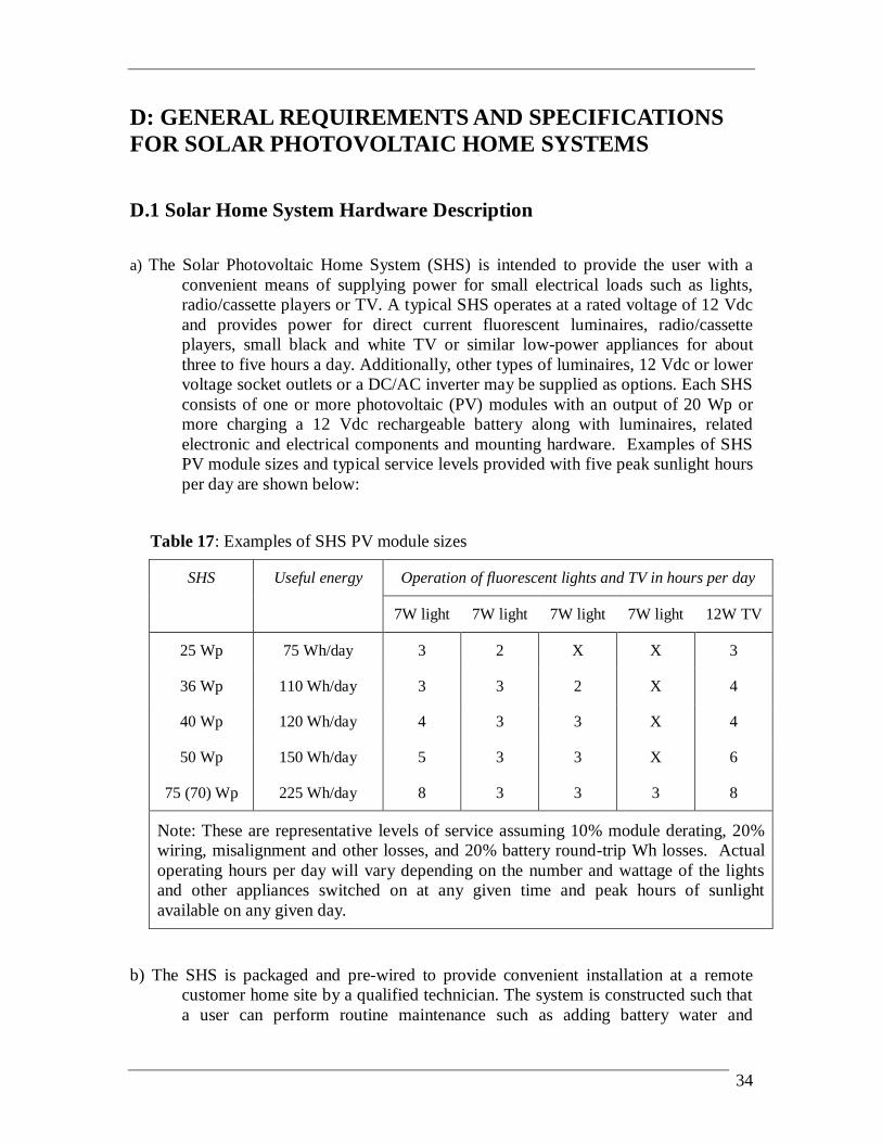
D.1 Solar Home System Hardware Description a) The Solar Photovoltaic Home System (SHS) is intended to provide the user with a
convenient means of supplying power for small electrical loads such as lights, radio/cassette players or TV. A typical SHS operates at a rated voltage of 12 Vdc and provides power for direct current fluorescent luminaires, radio/cassette players, small black and white TV or similar low-power appliances for about three to five hours a day. Additionally, other types of luminaires, 12 Vdc or lower voltage socket outlets or a DC/AC inverter may be supplied as options. Each SHS consists of one or more photovoltaic (PV) modules with an output of 20 Wp or more charging a 12 Vdc rechargeable battery along with luminaires, related electronic and electrical components and mounting hardware. Examples of SHS PV module sizes and typical service levels provided with five peak sunlight hours per day are shown below:
Table 17: Examples of SHS PV module sizes
SHS Useful energy
Operation of fluorescent lights and TV in hours per day
7W light 7W light 7W light 7W light 12W TV
25 Wp 75 Wh/day 3 2 X X 3
36 Wp 110 Wh/day 3 3 2 X 4
40 Wp 120 Wh/day 4 3 3 X 4
50 Wp 150 Wh/day 5 3 3 X 6
75 (70) Wp 225 Wh/day 8 3 3 3 8
Note: These are representative levels of service assuming 10% module derating, 20% wiring, misalignment and other losses, and 20% battery round-trip Wh losses. Actual operating hours per day will vary depending on the number and wattage of the lights and other appliances switched on at any given time and peak hours of sunlight available on any given day.
b) The SHS is packaged and pre-wired to provide convenient installation at a remote customer home site by a qualified technician. The system is constructed such that a user can perform routine maintenance such as adding battery water and

35
replacing light bulbs and fuses, and a technician can easily perform system diagnostics or replace components.
D.2 Certification Requirements a) Products to be financed under this Project must have a type-test certificate from
an accredited testing and certification organization acceptable to the Republic of Mozambique. The SHS should meet or exceed the specifications given in attachment 1. Organizations accredited according to ISO 25 or equivalent standards will be acceptable for issuing the component certifications.
b) SHS components or systems that bear the Photovoltaic Global Approval
Program (PV GAP) Mark or Seal will be acceptable for use in the SHS Project. 2
c) A maximum measurement error of 3 percent is permitted on all tests of compliance.
d) The supplier provides the most appropriate system integration, components,
assembly and packaging that meet all the component specifications in Attachment 1 - Solar Home System Component Specifications and the best practices recommendations in Section D.3.
D.3 Recommended Best Practices This section provides a minimum set of requirements that shall be followed in the design, specification and installation of the qualified SHS. They form a set of “Best Practices” which when followed will ensure adequate levels of safety, performance, reliability and system lifetime. Suppliers are required to adhere to these Best Practices in order to participate in the Project.
D.3.1 Photovoltaic Module Installation a) If more than one module is used, identical models shall be used and
they shall be connected in parallel.
2 PV GAP is a Geneva, Switzerland-based, not-for-profit international organization, dedicated to the sustained growth
of global photovoltaics (PV) markets to meet energy needs worldwide in an environmentally sound manner. For more information see http://www.pvgap.org/.

36
b) For SHS installed permanently on a structure (in contrast with portable units): The modules must be framed in such a way as to allow secure connection to the module mounting structure. i. The array mounting structure will hold the photovoltaic
module(s). The module(s) must be mounted on a support structure made of corrosion resistant material that assures stable and secure attachment.
ii. The PV array and support structure must be able to withstand wind gusts up to 120 km/hour without damage.
iii. The structure must be mounted at a fixed angle and oriented to maximize the useful energy supplied to the user during the design month (i.e., the month with the worst average daily insolation). Array orientation must be adjustable in the field.
iv. The structure will incorporate corrosion resistant hardware for all external connections. These include the modules to structure, structure to pole and pole to building attachments.
v. The modules can be roof or ground-mounted.
Roof-mounting: Minimum clearance between the PV array and the roofing material must be at least 10 cm above the roofing material. It is recommended that the module mounting structure be supported on top of a pole of at least 50 cm length. Anchoring of the mounting structure must be to the building and not to the roofing material.
Ground-mounting: A metal, concrete or treated wood pole must be used with the modules attached at the top of the pole. The modules must be at least 4 meters off the ground. The pole must be anchored in concrete or tightly packed soil at least one meter deep in the ground. The pole and mounting structure must be sufficiently rigid to prevent twisting in the wind or if large birds alight on the array. Ground mounted array is required to be fenced in.

37
D.3.2 Circuit Protection and Charge Controls a) Systems must include means to protect users and system components
from the following: i. Battery overcharge and excessive water loss.
ii. Battery undercharge and excessive deep discharge. iii. Circuit protection against short circuit of any load.
iv. Circuit protection against reverse polarity of any load. v. Circuit protection against reverse polarity of module or battery.
vi. Circuit protection against internal shorts in charge controller, inverter or other devices.
vii. Circuit protection against damage by the high PV open circuit voltage when it is connected to the controller without battery.
viii. Protection of controls against lightning induced transients when installed in a lightning prone area.
ix. Night time discharge of the battery due to reverse current through the array.
b) This protection will be provided by a charge controller incorporating a high voltage disconnect (HVD), low voltage disconnect (LVD) and circuit protection. Devices that integrate the following into a single device are strongly encouraged for all SHS sizes but alternate approaches will be considered.
c) A solid state photovoltaic charge controller is required for all systems (PWM).
D.3.3 System Monitoring a) A display to indicate when the battery is in the charging mode must be
provided.
b) Some form of a Battery State-of-Charge indicator must be provided on or near the controller or load center.
c) This device must, at a minimum, indicate when the battery condition is:
Suitable to operate loads (e.g. voltage greater than 12.5 Vdc)
Energy conservation required (e.g., battery voltage less than 11.8 Vdc)
The indicators may be LED's, LCDs, or analogue or digital meters.

38
d) The chosen device must come appropriately labeled so that the user does not have to refer to a manual to understand the existing battery condition.
D.3.4 Batteries a) Tubular plate / Deep cycle batteries are preferred (except for solar
lanterns).
c) Minimum battery capacity shall be determined to provide a minimum 3 days of storage (i.e., 3 days of autonomy). System design shall limit the maximum depth of discharge (DOD) to about 75% of rated capacity. Excessive over-sizing of the battery should be also avoided as it can lead to prolonged operative at lower states of charge and shorten battery life.
Example: For shallow cycle battery such as an automotive battery, the 20-hour ampere-hour (Ah) capacity at 12 V DC, measured at 25°C, should be such that it will permit three days of autonomy where the maximum depth of discharge is limited to 75 percent of rated capacity. The typical acceptable Ah capacity for a battery for various sizes of PV modules is shown in the table below. Table 18: Typical acceptable Ah battery capacity for different PV modules size
Module Average daily Ah to load at 12 V DC
(Daily Ah x 3 days of autonomy)/0.75
Typical battery size ranges
Rating (Wp) (Ah at 20-hour rate)
20 4.8 19.2 15-25
30 7.2 28.8 25-35
40 9.6 38.4 35-45
50 12 48 45-60
60 14.4 57.6 60-70
75 18 72 70-90
Note: The battery Ah capacity should not be more than 25 times the PV module short circuit current Isc. For a 50W module Isc=2.9 A, then the maximum battery capacity should be 2.9x25=80 Ah.
d) Batteries should be selected and sized to offer a three year useful life under anticipated operating conditions.

39
e) For flooded-electrolyte type cells, the electrolyte volume must be sufficient to allow at least eight weeks of continuous operation of the SHS as per specification without the addition of distilled water.
f) The batteries can be supplied either in a wet-charged or dry-charged condition. If dry-charged, all chemicals and electrolyte must be supplied in accordance with battery supplier specifications. The battery and associated containers should be packaged to handle transport down rough dirt roads.
D.3.5 DC/AC Inverters In general, DC appliances are preferred in order to avoid inverter energy losses. Use of inverters is not recommended for systems smaller than 70 Wp.
D.3.6 Equipment Enclosure a) The battery must be housed in a vented compartment. All parts of the
compartment subject to battery acid contact must be acid resistant. This compartment must be built strong enough to accommodate the weight of the battery. This compartment must adequately support and vent wet, lead-acid batteries. Access to the battery compartment by children must be prevented.
b) The remainder of the system components (electronics, switches etc.) must be housed in a separate compartment or enclosures which prevents the system components being affected by battery acid spills or fumes. The compartment or enclosure design must allow the internal electronic equipment to operate within acceptable operating temperature limits.
c) The enclosure must be constructed of a durable material so as to last 10 years without maintenance.
D.3.7 Wiring a) Stranded and flexible insulated copper wiring must be used. Minimum
acceptable cross-section of the wire in each of the following sub-circuits is as follows:
i. From PV module to regulator/controller: AWG#14 (2.1 mm²) for systems 20W to 39W and AWG#12 (3.3 mm²) for systems 40W to 75W
ii. From regulator/controller to battery: AWG#14 (2.1 mm²) for systems 20W to 39W and AWG#12 (3.3 mm²) for systems 40W to 75W

40
iii. From controller to loads: AWG#14 (2.1mm²)
b) Not withstanding the above minimum wire size requirements, all wiring must be sized to keep line voltage losses to less than 5% in each sub-circuit and to allow the circuit to operate within the ampacity rating of the wire.
c) For SHS permanently installed on a structure, all exposed wiring (with the possible exception of the module interconnects) must be in conduits or be firmly fastened to the building structure. Wiring through roofing, walls and other structures must be protected through the use of bushings. Wiring through roofing must form a water-proof seal. Where the wiring is through flammable material (e.g. thatched roofs), they must be in a metal conduit. Adequate fasteners, conduits, bushings and other installation hardware must be supplied.
d) Field-installed wiring must be joined using terminal strips or screw connectors. Soldering or crimping in the field must be avoided if at all possible. Wire nuts are not allowed. The rated current carrying capacity of the joint must not be less than the circuit current rating. All connections must be made in junction boxes. Fittings for lights, switches, and socket outlets may be used as junction boxes where practical.
e) All wiring shall be colour coded and/or labeled.
D.4 Documentation The component specifications should be summarized in Attachment 2 - Solar Home
System Specification Data Sheet along with the required test certificates. Any exceptions and variations to the specifications must be explicitly stated in a section entitled Exceptions and Variations in Attachment 2. The scope and reasons for each listed exception and variation must be fully explained with supporting data.
D.4.1 Users Manual The solar home system (SHS) supplier must provide a User’s Manual
intended for the customers and will be included with each of the packaged systems. The manual must be in local language understandable by the users. The User’s Manual documentation should be simple and easy to understand. Use of sketches or graphics should be used to make the manual easier to use. The documentation is to include the following: a) How the SHS works: battery charging by the array, functions, battery
low voltage protection, and battery overcharge protection. The relationship between energy available on a daily basis and sunlight conditions should be clearly and simply explained.

41
b) A description of all user interactive hardware including disconnect switches and status indicators.
c) Procedures for proper system operation, including a list of load limitations and any problem loads. These procedures should include suggested operation, including load conservation, during periods of inclement weather, and/or a low voltage disconnect event. The procedures for checking that the photovoltaic array is not shaded and how to prevent shading must be explained. For portable SHS, instructions must be given on how to orient the PV module to maximize energy generation. For systems without charge controllers, procedures for preventing overcharging must be given.
d) Any user maintenance items.
e) Emergency shut down procedures and recommendations for extended periods of system non-use.
f) A user trouble shooting guide. g) A block diagram showing the main components.
D.4.2 Technicians Manual The supplier must provide a Technician’s Installation, Operations and
Maintenance Manual to be used by the service technicians. The manual must be in a language understandable by the technicians. The manual will include the specific details on installation, operation and maintenance a) A detailed technical description of the system.
b) A complete copy of the Users Manual. c) A complete list of all system components, with associated
manufacturers literature, specifications, and warranties. d) Complete installation instructions.
e) A Post-Installation Checklist, that will confirm proper installation and handover, including:
i) Verify that the installation of the photovoltaic array with regard to position, direction, inclination and shading avoidance will maximize energy generation.
ii) Ensure that the battery has received an equalization charge just before installation.
iii) How to use a shunt to measure the current and voltage from the array under charging conditions to verify the array charging current.
iv) Test all of the loads for proper operation.

42
v) Make system-wide voltage drop measurements in the sub-circuits to verify that connections meet the required maximum allowable voltage drop.
vi) Note all measurements in the installation log.
vii) Explain to the user the system operating principles, load management requirements, impact of shading of the array and how to check and avoid it, user maintenance checks and how to conduct them.
f) A recommended annual maintenance schedule, with complete maintenance instructions.
g) A detailed trouble shooting guide referencing all the system components. This shall include repairs and diagnostic procedures that can be done by the supplier or a qualified third party. Repairs and procedures not to be attempted by non-electricians and/or electricians unfamiliar with photovoltaic systems shall also be identified.
h) A functional block diagram, electrical single-line drawing showing the placement of all hardware and ratings of all component and physical layout diagram.
D.5 Packaging and Delivery a) The SHS supplier must obtain the PV system equipment and components,
assemble and wire them into integrated packaged SHS in accordance with the proposed design, and deliver the packaged SHS to the user.
b) Each system must be packaged for shipping to prevent any shipping related damage. The supplier will be responsible for settling any shipping related damaged claims and will be responsible for replacing damaged systems in a timely manner.

43
ATTACHMENT 1 SOLAR HOME SYSTEMS COMPONENT SPECIFICATIONS
1. General
1.1. The supplier will provide at a minimum a one year warranty against manufacturers defects on all system integrated parts and labor excluding fuses or end-use devices such as luminaires or lamps. On all major individual components, manufacturers warranties will be passed through to the user. Specifically, the PV modules should be warranted against reduction of output of no more than 10 percent of rated capacity over a minimum of ten year period. The charge controller, low voltage disconnect, switches, and charge indicators should be warranted for at least one year. The battery should be warranted for at least one year. Battery end-of-life will be determined when the battery capacity down to 1.75 V/cell at 25 degrees centigrade drops to less than 80 percent of the initial rated capacity. All warranties will start from the day the system is installed and accepted by the user.
1.2. Nominal system voltage (rated voltage) shall be 12 Vdc. 1.3. The entire SHS system must be designed and constructed so that it requires
maintenance and inspection by a technician no more frequently than once every six months.
1.4. The main components shall be integrated in such a way as to allow replacement (in case of failure) with a similarly functioning component of a newer design or a different brand. This will allow for future component evolution or variability of future component availability.
1.5. With the exception of the PV module(s), the supplier shall deliver the system to the user with as many components pre-assembled and pre-wired as is feasible prior to shipment.
1.6. All components, including spares, will undergo full bench testing at the supplier factory or the originating source factory with proper documentation supplied. All set point voltages will be verified and documented with the results dated and the records maintained at the suppliers facility.
2. References
The following are applicable standards:

44
a) International Electrotechnical Committee (IEC) 61215: 1993 Crystalline Silicon Terrestrial PV Modules – Design Qualification and Type Approval
b) IEC 61646: 1996 Thin Film Silicon Terrestrial PV Modules – Design Qualification and Type Approval
c) IEC 60904-1:1987 Photovoltaic Devices Part 1 – Measurement of PV Current-Voltage Characteristics
d) IEEE 1262: 1995 Recommended Practice for Qualification of Photovoltaic Modules, April 1996
e) IEC Standard 61427 © IEC:2001 Ed.2, Secondary Cells and Batteries for Solar Photovoltaic Energy Systems – General Requirements and Methods of Test
f) PV GAP Recommended Standards (various) See “Standards and Blank Detailed Specifications in http://www.pvgap.org for updated list.
3. Operating Environment 3.1. The entire system shall be designed and built to withstand the environmental
conditions found in Mozambique. For design purposes, consider that temperature extremes could range from 0 to +45 degrees Centigrade and humidity levels could reach 90 percent.
3.2. All wiring, enclosures, and fixtures must be resistant to high humidity conditions, corrosion and insect and dust intrusion. In particular, electronic components and circuitry used in coastal areas subject to humid and salty conditions should have protective coatings to resist corrosion.
4. Photovoltaic Array 4.1. The photovoltaic array will consist of one or more flat-plate photovoltaic
modules. Each module should comprise of no less than 36 series-connected single or poly-crystalline silicon solar cells. Flat plate thin-film modules could also be used.
4.2. The photovoltaic array should have a peak power output of at least 20 Wp, under Standard Test Conditions (STC) as defined in IEC 60904-1. The peak power output for thin film modules should be the value after light soaking.
4.3. Crystalline modules are required and the relevant PV GAP standard is PVRS 2 “Crystalline silicon terrestrial Photovoltaic (PV) modules”. The applicable international standards for PV modules is IEC 61215: 1993 Crystalline Silicon Terrestrial PV Modules – Design Qualification and Type Approval.
4.4. Each module must be factory equipped with either (a) weather-proof junction box with terminal strip that allows safe and long lasting wiring connection to the

45
module, or (b) output cable that connects the module via a sealed weather proof termination.
4.5. Each module must be labeled indicating at a minimum: Manufacturer, Model Number, Serial Number, Peak Watt Rating, Peak Current, Peak Voltage, Open Circuit Voltage and Short Circuit Current of each module.
5. Battery Storage 5.1. The applicable standards are: IEC Standard 61427 © IEC:2001 Ed.2, Secondary Cells and Batteries for
Solar Photovoltaic Energy Systems – General Requirements and Methods of Test.
5.2. The maximum permissible self-discharge rate is 10 percent of rated capacity per month at 25 degree Centigrade.
5.3. For a flat plate battery, after it has gone through 3 test sequences according to IEC Standard 61427 IEC:2001 Ed.2 "Secondary Cells and Batteries for Solar Photovoltaic Energy Systems - General Requirements and Methods of Test" (a test sequence is defined as going through one complete procedure defined in paragraphs 6.4.1, 6.4.2 and 6.4.3 of IEC 61427),3 the battery should yet retain at least 80 percent of its initial C10 capacity (according to end-of-test condition as defined in paragraph 6.4.4.4. Similarly, for tubular plate battery, after it has gone through 8 test sequences as defined above5, the battery should yet retain at least 80 percent of its initial C10 capacity according to test procedures given in draft IEC Standard 61427 standard.
6. Charge Controller 6.1. The relevant PV GAP Standard is PVRS 6 “Charge controllers for photovoltaic
(PV) stand-alone systems with a nominal system voltage below 50 V”.
6.2. Charge Controllers that are not PV GAP certified shall comply with the Project component specifications given below.
6.3. The charge controller set points must be factory preset with the set points applicable to the specified battery characteristics to prevent battery over-charge (high-voltage-disconnect and reconnect set points) or over-discharge (low-voltage-disconnect and reconnect set points). It is recommended that circuitry to
1 This is equivalent to approximately 125 times its rated capacity [i.e., (Sum of Ah delivered)/(Rated Ah capacity)]. 4 Note that test should not be stopped if voltage drops below 1.5 volt/cell and only the actual discharge should be
stopped and the test is continued with the following recharge. 5 Equivalent to cumulatively delivered 335 times its rated capacity.

46
allow periodic equalizing charging of the battery be provided. Control set points for charging, discharging and other functions must be sufficiently stable to insure proper operation of the device over the range of anticipated ambient temperatures where the device will be installed.
6.4. The charge controller must be capable of handling 125% of the array's rated short circuit current for one hour duration.
6.5. The charge controller must be of the type Pulse Width Modulation (PWM). 6.6. The charge controller must have a temperature compensation.
6.7. The charge controller must be able to withstand 125% of the array’s rated open circuit voltage with the battery removed from the circuit for one hour duration.
6.8. The low voltage disconnect must be capable of handling at least 150 percent of the maximum expected continuous load (assuming all end use devices are on simultaneously).
6.9. Maximum current draw of the controller, when no LED’s are lit should not exceed 10 mA.
6.10. Controller should include the following protective features:
a) Battery overcharge and over-discharge protection b) Short circuit of any load
c) Reverse polarity of any load d) Reverse polarity of module or battery
e) Internal shorts in charge controller. f) Lightning induced transients when use in lightning-prone areas is
expected. g) Night time discharge of the battery due to reverse current through the
array. 6.11. Some means must be provided to safely disconnect the battery and the module
during servicing or repair by a technician. 6.12. The model number, serial number, rated voltages and currents, and set points
should be noted on the charge controller case.
7. Fluorescent Luminaires 7.1. The relevant PV GAP standard is “PVRS 8 “Inverters for photovoltaic (PV)
stand-alone systems”.
7.2. DC/AC Inverters that are not PV GAP certified shall comply with Project component specifications given below.
7.3. Each fluorescent luminaire should have its own inverter (electronic ballast).

47
7.4. The inverter electrical efficiency must be greater than 80 percent from 11.0 to 13.3 V when using the fluorescent lamp specified by the luminaire supplier.
7.5. Luminous efficacy should be at least 50 Lumen/Rated Watt (rated voltage times rated current of the lamp and not the rating of tube), at nominal voltage.
7.6. The minimum operating voltage when the tube will strike (start) should be at least 85% of the rated input voltage when using the fluorescent lamp specified by the luminaire supplier.
7.7. Maximum continuous operating voltage without damage to the inverter circuit must be at least 125% of the rated voltage.
7.8. The minimum operating frequency should be greater than 20 kHz.
7.9. The electrical waveform at the fluorescent lamp terminals must be symmetrical in time to within 10 percent (i.e., 60%/40% waveform maximum difference in symmetry over the voltage range of 11.0 to 12.5 Vdc at an ambient temperature of 25 degree C)
7.10. Tolerance limits of the waveform test criteria at minimum operational frequency of 20 kHz, must be a crest factor ranging between 1.3 to 2. The direct current components of the lamp operating current may not exceed 2 % of the r.m.s.
7.11. The input connections to the inverter should prevent the application of voltage with reverse polarity, or the inverter should be protected against damage when the rated voltage is applied with reverse polarity.
7.12. The inverter should be protected against damage by the application of voltage under open circuit conditions (e.g., when the light bulb is removed or has failed). The maximum input current draw under open circuit conditions should be no more than 200 mA.
7.13. The electronic ballast/lamp combination should withstand 5000 switching cycles with each cycle consisting of 60 seconds on and 150 seconds off.
7.14. The lifetime of the tube must exceed 2000 hours when operating at rated voltage. At the end of 2000 hours, luminous efficacy should be at least 25 lumens/ rated W.
7.15. Inverter or the luminaire must be marked with the manufacturer, model number, rated voltage, wattage and date of manufacture or batch number.
8. DC/AC Inverters

48
8.1 The relevant PV GAP standard is “PVRS 8 “Inverters for photovoltaic (PV) stand-alone systems”.
8.2 DC/AC Inverters that are not PV GAP certified shall comply with Project component specifications given below.
8.3 Rated output voltage shall be AC 220V±10% over the full range of normal battery operating voltages. That is, when the input DC voltage varies from 90% to 120%, the output AC voltage must be within 10% of the rated voltage.
8.4 Output frequency is 60Hz and the variation should not be over 5%.
8.5 Inverters must be of the type Pulse Width Modulation (PWM). 8.6 Inverters must have a temperature compensation.
8.7 Inverter shall be capable of: a) Operating continuously for 4 hours at its rated power under ambient
temperatures of 25°C. b) Operate safely for at least one minute at 125% of rated power.
c) Provide 150% of rated power for at least two 2 seconds to facilitate starting of motors and other high capacitance loads.
8.8 Inverter efficiency when operating resistive loads and power levels of above 75% should be greater than 90%.
8.9 Inverter or inverter circuits must include protection against: a) Low voltage: when input voltage is less than 1.8V/battery cell.
b) Over-current: when working current is greater than 150% of the rated current.
c) Short circuit of input and output terminals. d) Reverse polarity on DC input terminals.
e) Lightning induced transients when use in lightning-prone areas is expected.
8.10 The maximum quiescent current draw of the inverter, when no LEDs are illuminated, must not exceed 3% of the rated input current of the inverter.
8.11 Quiet operation: The noise produced by the inverter should be no more than 65dB at a distance of 3 meters from the inverter.
8.12 Easy to service: The inverter should be easy to repair or replace in the field by the service technicians.
8.13 The inverter input and output terminals must not be exposed to contact by the user and must be securely mounted in a location which is not accessible by children.
8.14 Each inverter must be labeled with the minimum information:
a) Manufacturer name and model

49
b) Serial number c) Input and output voltage and rated power
d) Battery and load connection points and polarity
9. Socket Outlet 9.1. A 12 Vdc and/or lower voltage socket outlet for a radio/cassette player, TV or
similar appliance must be rated to carry the maximum expected DC current. The outlet must be protected from reversing the polarity of the voltage applied to the appliance.

50
ATTACHMENT 2
Solar Photovoltaic System Data Sheet
1. Photovoltaic Module(s) (a) Model Number _______________________________________________________
(b) Type (a-Si, crystalline Si,. etc.) __________________________________________
(c) Number of cells in series _______________________________________________
(d) Rated peak power (Pmax @ STC) _____________________________________ Wp
(e) Open circuit voltage__________________________________________________ V
(f) Short circuit Current _________________________________________________ A
(g) V max @ STC ______________________________________________________ V
(h) I max @ STC _______________________________________________________ A
(i) NOCT ________________________________________________________ deg C
(j) Test Certification Standard _____________________________________________
(k) Test Laboratory ______________________________________________________
(Attach I-V curve and copy of test certificate)
2. Support Structure
(a) Type ______________________________________________________ (roof/pole)
(b) Material ____________________________________________________________
3. Battery Storage (a) Model Number _______________________________________________________
(b) Number of batteries ___________________________________________________
(c) Rated voltage _______________________________________________________ V
(d) Structure and material of positive plate ____________________________________
(e) Capacity per battery at C/20 down to 1.75V/cell __________________________ Ah
(f) Self discharge rate __________________________________________ (%/month)
(g) Cycle life down to __ percent of its initial C10 capacity_______________________
(h) Electrolyte volume ________________________________________________ liters
(Attach test certificate: certification of passing battery interim test should be provided prior to installation and IEC or PVGAP test certification should be provided within one year)
4. Charge Controller (a) Model number _______________________________________________________

51
(b) Rated voltage _______________________________________________________ V
(c) Boost charging method ________________________________________________
(d) Maximum current handling capability____________________________________ A
(e) Maximum current draw when no LED’s are lit __________________________ mA
(f) Type of current leakage protection _______________________________________
(g) Short circuit protection? _________________________________________ Yes/No
(h) Reverse polarity protection? ______________________________________ Yes/No
(i) Over current protection? _________________________________________ Yes/No
(j) Battery open circuit protections ____________________________________ Yes/No
(k) Lightning surge protection? _______________________________________ Yes/No
(l) Module/battery/loads disconnection method ________________________________
(m) LVD maximum current handling capability _______________________________ A
(n) LVD set points
(i) Disconnect voltage ________________________________________________ V
(ii) Reconnect voltage ________________________________________________ V
(o) HVD set points
(i) Disconnect voltage ________________________________________________ V
(ii) Reconnect voltage ________________________________________________ V
(Attach test certificate)
5. System Monitoring (a) Charging indicator type ________________________________________________
(b) Battery State-of-Charge meter/indicator? ____________________________ Yes/No
(c) Type of Indicator _____________________________________________________
(d) Indications Settings
(i) Fully Charged Suitable to Use _______________________________________ V
(ii) Energy Conservation ______________________________________________ V
(iii) Other (explain) ___________________________________________________
6. Equipment Enclosure (a) Type of battery enclosure ______________________________________________
(b) Material ____________________________________________________________
(c) Type of controller housing _____________________________________________
(d) Material ____________________________________________________________
(e) Protection method against battery acid/fumes etc. ___________________________

52
7. Wiring (a) Wire material type ____________________________________________________
Wire cross-sections
(b) PV module to controller ___________________________________________ mm2
(c) Controller to battery_______________________________________________ mm2
(d) Controller to loads ________________________________________________ mm2
(e) Wiring identification method (colour coded/labeled) _________________________ .
9. Luminaire (a) Number of luminaire __________________________________________________
(b) Model number(s) _____________________________________________________
(c) Wattage(s) ________________________________________________________ W
(d) Inverter electrical efficiency __________________________________________ %
(e) Luminous efficacy __________________________________________________ %
(f) Maximum continuous operating voltage __________________________________ V
(g) Operating frequency _______________________________________________ kHz
(h) Electrical waveform voltage symmetry ____________________________________
(i) Maximum crest factor _________________________________________________
(j) Open circuit voltage protection? __________________________________ (Yes/No)
(k) Current draw on open circuit? _______________________________________ mA
(l) Short circuit protection? ________________________________________ (Yes/No)
(m) Reverse polarity protection? _____________________________________ (Yes/No)
(n) Switching cycles ______________________________________________ (number)
(o) Tube lifetime __________________________________________________ (hours)
(Attach test certificate)
9. DC/AC Inverter (a) Manufacturer .................................................................................................................... (b) Model Number ................................................................................................................. (c) Continuous Power ........................................................................................................ W (d) Rated Output AC Voltage ..................................................................................... V__% (e) DC Input Voltage Range ...................................................................................... V__% (f) Output Frequency ................................................................................................ Hz__% (g) Inverters Type .........................................................................Sine/Modified Sine/Square (h) Efficiency at 25% Rated Capacity .................................................................................. % (i) Efficiency at Rated Capacity.......................................................................................... % (j) Low Voltage Protection ........................................................................................... V/cell (k) Over-current Protection ........................................................................................ Yes/No

53
(l) Short-circuit Protection ......................................................................................... Yes/No (m) Input Terminal Reverse Polarity Protection........................................................... Yes/No (n) Lightning Protection ............................................................................................. Yes/No (o) Label .................................................................................................................... Yes/No (p) Documentation ..................................................................................................... Yes/No (q) Certification Issued By ..................................................................................................... (Attach copy of certificate)
10. Socket Outlet (a) Socket outlet? ________________________________________________ (Yes/No)
(b) Reverse polarity protection? _____________________________________ (Yes/No)
(c) Voltage ___________________________________________________________ V
11. Other Components/Features (a)
(b)
(c)
(d)
12. Exceptions and Variations to the Specifications Taken and Explanation
13. List of Spare Parts

54
ANNEXES

55
ANNEX 1 - MAP OF MOZAMBIQUE

56
ANNEX 2 - MAP OF MANICA PROVINCE

57
ANNEX 3 - MAP OF TETE PROVINCE

58
ANNEX 4 – TABLE OF DISTANCES
Province (A)
District (B)
"Posto Administrativo" (C)
Distance between A and B (Km)
Distance between B and C (Km)
Tete
Zumbe Muze 468 137.37
Chifunde Mualadzi 190.2 238
Maravia Malowera 224.6 78.06
Manica
Manica Mavonde 69.48 40.82
Guro Mungari 215 42

59
ANNEX 5 – ENVIRONMENTAL CHARACTERISTICS6 A. DATA ON TEMPERATURE, SOLAR RADIATION AND RAINFALL FOR TETE PROVINCE
Jan Feb Mar Apr May Jun Jul Aug Sep Oct Nov Dec Average
/Total7 Monthly averages of
max temp (oC) 33.6 33.4 33.5 32.9 31.2 28.9 29.0 30.8 33.7 36.1 36.6 34.7 32.9
Monthly averages of mean temp (oC) 28.6 28.4 28.3 27.3 25.0 22.4 22.1 24.2 27.0 29.5 30.3 29.1 26.9
Monthly averages of min temp (oC) 23.6 23.5 23.0 21.5 18.5 16.2 15.8 17.5 20.3 22.8 24.0 23.7 20.9
Monthly mean global solar radiation
(kWh/m2/day)
6.6 6.2 6.3 5.7 5.1 4.6 4.7 5.2 5.8 6.1 6.8 6.6 5.8
Monthly rainfall (mm) 166.7 152.7 87.2 17.1 5.8 3.4 3.3 1.6 1.4 12.3 51.8 140.7 644.0
6 Data measured by the National Institute of Meteorology during the period from 1975 to 2005. 7 Average values were calculated for the temperature and solar radiation, while for rainfall a total annual value was considered.

B. DATA ON TEMPERATURE, SOLAR RADIATION AND RAINFALL FOR MANICA PROVINCE
Jan Feb Mar Apr May Jun Jul Aug Sep Oct Nov Dec Average
/Total8 Monthly averages of
max temp (oC) 28.5 28.0 27.7 26.5 25.2 23.2 23.0 24.8 27.4 28.9 29.1 28.5 26.7
Monthly averages of mean temp (oC) 23.9 23.8 23.1 21.5 19.7 17.7 17.4 18.9 21.2 22.9 23.7 23.8 21.5
Monthly averages of min temp (oC) 19.5 19.5 18.6 16.8 14.2 12.2 11.8 12.9 14.9 16.8 18.2 19.1 16.2
Monthly mean global solar radiation (kWh/m2/day)
6.7 6.5 6.2 5.5 4.9 4.5 4.7 5.3 5.9 6.2 6.6 6.1 5.8
Monthly rainfall (mm) 214.0 221.7 152.1 55.9 21.5 14.8 20.6 15.8 18.0 46.9 90.9 198.2 1070.4
8 Average values were calculated for the temperature and solar radiation, while for rainfall a total annual value was considered.