topic 2: power system harmonics part iii: part iii: impact
TRANSCRIPT

POWER SYSTEMS QUALITYPOWER SYSTEMS QUALITY Topic 2: Topic 2: Power System HarmonicsPower System Harmonics
Part III:Part III: Impact of HarmonicEE589EE589--Power System Quality & Power System Quality & HarmonicsHarmonics
Dr. E. A. Dr. E. A. FeilatFeilatElectrical Engineering DepartmentElectrical Engineering Department
School of EngineeringSchool of EngineeringUniversity of JordanUniversity of Jordan
1Dr. E. A. Feilat

Effect of Harmonic DistortionEffect of Harmonic Distortion
2Dr. E. A. Feilat

Harmonic currents produced by nonlinear loads are injected back into the supply systems.
These currents can interact adversely with a wide range of power system equipment, most notably capacitors, transformers, and motors, causing additional losses, overheating, and overloading.
These harmonic currents can also cause interference with telecommunication lines and errors in power metering.
Effect of Harmonic DistortionEffect of Harmonic Distortion
3Dr. E. A. Feilat

Effects of Harmonic DistortionEffects of Harmonic Distortion• Short-Term Effects (Noticeable)Excessive Voltage Distortion (>10%)Voltage flicker due to InterharmonicsCause Nuisance Tripping of Sensitive Loads (Computer-
Controlled Loads), Relays, Plc, etc..Fuse Operation (Burning)Resonance Problems –
Pulsating Torques in motors (-ve sequence harmonics )Radio Interference
•
Long-Term Effects (Undetected) Increased Resistive Losses or Voltage Stresses
4Dr. E. A. Feilat

Effects of Harmonic Distortion
•
Impact on CapacitorsBlown Capacitor FusesFailed Capacitor Cans
Harmonic Voltages Excessive Harmonic Currents (i=dv/dt).
5-10% Voltage Distortion Increase rms Current by 10-50%.
Overvoltage Stress on Dielectric Capacitor Failure
A 10%Harmonic Voltage for any Harmonic above the 3rd
increases the Peak Voltage by 10%
5Dr. E. A. Feilat

Problems involving harmonics often show up at capacitor banks first.
A capacitor bank experiences high voltage distortion during resonance.
The current flowing in the capacitor bank is also significantly large and rich in a monotonic harmonic.
The harmonic current shows up distinctly, resulting in a waveform that is essentially the 11th
harmonic tiding on top of the fundamental frequency.
Impact on CapacitorsImpact on Capacitors
6Dr. E. A. Feilat

Current waveform of a capacitor bank in resonance with the system at the 11th
harmonic.
Impact on a Capacitor
7Dr. E. A. Feilat

This current waveform typically indicates that the system is in resonance and a capacitor bank is involved. In such a resonance condition, the rms
current is typically higher than the capacitor
rms
current rating.
IEEE Standard for Shunt Power Capacitors (IEEE Standard 18-
1992) specifies the following continuous capacitor ratings:
135 percent of nameplate kvar
110 percent of rated rms
voltage (including harmonics but excluding transients)
180 percent of rated rms
current (including fundamental and harmonic current)
120 percent of peak voltage (including harmonics).
Impact on Capacitors
8Dr. E. A. Feilat

Allowed Operation Limits for Shunt Capacitor Bank
► 135 percent of nameplate kvar► 110 percent of rated rms
voltage (including harmonics
but excluding transients)► 135 percent of rated rms
current (including fundamental
and harmonic current)► 120 percent of peak voltage (including harmonics)
IEEE Standard for Shunt Power Capacitors (IEEE Standard 18- 2000) specifies the following continuous capacitor ratings:
9Dr. E. A. Feilat

The Table summarizes an example capacitor evaluation using a computer spreadsheet that is designed to help evaluate the various capacitor duties against the standards.
The fundamental full-load current for the 1200-kVAR capacitor bank is determined from
The capacitor is subjected principally to two harmonics: the 5th
and the 7th. The voltage distortion consists of 4% percent fifth and 3% 7th.
This results in 20% 5th harmonic current and 21% 7th
harmonic current.
The resultant values all come out well below standard limits in this case, as shown in the box at the bottom of the Table.
Impact on Capacitors
10Dr. E. A. Feilat

Impact on Capacitors
11Dr. E. A. Feilat

Effects of Harmonic Distortion
•
Impact on Transformers and Machines
Harmonics Cause Overheating of Transformers &
Machines
Conductor losses (I2rms R)
Eddy-Current Losses (PEC f 2)
Transformer Derating to 80% of KVArated when Serving
only One Large Nonlinear Load
12Dr. E. A. Feilat

Transformers are designed to deliver the required power to the connected loads with minimum losses at fundamental frequency.
Harmonic distortion of the current, in particular, as well as of the voltage will contribute significantly to additional heating.
To design a transformer to accommodate higher frequencies, designers make different design choices such as using:
continuously transposed cable instead of solid conductor
putting in more cooling ducts.
As a general rule, a transformer in which the current distortion exceeds 5 %
is a candidate for derating for harmonics.
Impact on Transformers
13Dr. E. A. Feilat

There are three effects that result in increased transformer heating when the load current includes harmonic components:
1.
RMS current. If the transformer is sized only for the kVA requirements of the load, harmonic currents may result in the
transformer rms
current being higher than its capacity. The increased total rms
current results in increased conductor losses.
2.
Eddy current losses. These are induced currents in a transformer caused by the magnetic fluxes. These induced currents flow in the windings, in the core, and in other conducting bodies subjected to the magnetic field of the transformer and cause additional heating. This component of the transformer losses increases with
the square of the frequency (f2) of the current causing the eddy currents. Therefore, this becomes a very important component of transformer losses for harmonic heating.
Impact on Transformers
14Dr. E. A. Feilat

3.
Core losses. The increase in core losses in the presence of harmonics will be dependent on the effect of the harmonics on the applied voltage and the design of the transformer core. Increasing the voltage distortion may increase the eddy currents in the core laminations. The net impact that this will have depends on the thickness of the core laminations and the quality of the core steel. The increase in these losses due to harmonics is generally not as critical as the previous two.
Guidelines for transformer derating
are detailed in ANSI/IEEE Standard C57.110-1998, Recommended Practice for Establishing Transformer Capability When Supplying Nonsinusoidal Load Currents.
Impact on Transformers
15Dr. E. A. Feilat

Impact of Harmonics on Transformers
The K factor commonly found in power quality literature concerning transformer derating
can be defined solely in terms of
the harmonic currents as follows:
max
max
1
2
1
22
h
hh
h
hh
I
hIK
Then, in terms of the K factor, the rms
of the distorted
current is derived to beREC
RECh
hh PK
PI
11max
1
2
where PEC – R = eddy current loss factorh = harmonic numberIh = harmonic current
Thus, the transformer derating
can be estimated by knowing the per-unit eddy current loss factor.
16Dr. E. A. Feilat

Impact of Harmonics on Transformers
17Dr. E. A. Feilat
1.Obtaining the factor from the transformer designer2.Typical values based on transformer type and sizeTypical per-unit eddy current loss factor values based on transformer type and size

K-Factor Transformer DeratingEXAMPLE
:The current through a 3MVA , 11000/690 V , 157.5/2510 A, -Yg, Z=1+j6.2 . By using the following table can the transformer operate in this harmonic environment? Assume PEC-R =15%.
%18.25%%2
2
11
2
2
h
hI
hh
I IITHD
I
ITHD
h 1 5 7 11 13 17 19 23 25Ih % (Primary) 100 19 13 8 5 3 2 1 0.9
Ih % (Secondary) 100 -19 -13 8 5 -3 -2 1 0.9
436.41
2
1
2
h
h
IIhK
The K-factor is: The normalized K-factor is:
172.40634.1436.4
25
1
2
1
25
1
2
1
2
h
h
h
h
II
IIh
K
(84.1%)or 0.841pu 15.0172.41
15.01
1125
1
2
1
REC
REC
h
h
PKP
II
The derating factor
0634.125
1
2
1
h
h
II
18Dr. E. A. Feilat

K-Factor Transformer DeratingK-factor transformers are designed to reduce the heating effects of harmonic
currents created by loads like those in the table below.
19Dr. E. A. Feilat

Impact on Motors
Motors can be significantly impacted by the harmonic voltage distortion. Harmonic voltage distortion at the motor terminals is translated into harmonic fluxes within the motor.
The effect on motors is similar to that of negative-sequence currents at fundamental frequency: The additional fluxes do little more than induce additional losses. Decreased efficiency along with heating, vibration, and high-pitched noises are indicators of harmonic voltage distortion.
20Dr. E. A. Feilat

Impact on Motors
There is usually no need to derate
motors if the voltage distortion remains within IEEE Standard 519-1992 limits of 5% THD and 3% for any individual harmonic.
Excessive heating problems begin when the voltage distortion reaches 8 to 10 % and higher. Such distortion should be corrected for long motor life.
21Dr. E. A. Feilat
st th th1 , 4 ,7
nd th th2 ,5 ,8

Impact on Telecommunications
Harmonic currents flowing on the utility distribution system or within an end-user facility can
create interference in communication circuits sharing a common path.
Voltages induced in parallel conductors by the common harmonic currents often fall within the bandwidth of normal voice communications.
Harmonics between 540 (9th
harmonic) and 1200 Hz are particularly disruptive.
The induced voltage per ampere of current increases with frequency.
22Dr. E. A. Feilat

Impact on Telecommunications●
Harmonic currents on the power system are coupled into communication circuits by either induction or direct conduction.
●
The Figure illustrates coupling from the neutral of an overhead distribution line by induction.
●
This was a severe problem in the days of open wire telephone circuits.
●
Now, with the prevalent use of shielded, twisted-pair conductors for telephone circuits, this mode of coupling is less significant. The direct inductive coupling is equal in both conductors, resulting
in zero
net voltage in the loop formed by the conductors.●
Triplen
harmonics (3rd
, 9th
, 15th
) are especially troublesome in four- wire systems because they are in phase in all conductors of a three-
phase circuit and, therefore, add directly in the neutral circuit, which has the greatest exposure with the communications circuit.
23Dr. E. A. Feilat

Impact on Telecommunications
Inductive coupling of power system residual current to telephone circuit.
24Dr. E. A. Feilat
Impact on Telecommunications
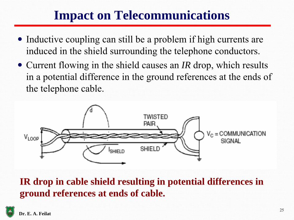
Inductive coupling can still be a problem if high currents are induced in the shield surrounding the telephone conductors.
Current flowing in the shield causes an IR drop, which results in a potential difference in the ground references at the ends of the telephone cable.
IR drop in cable shield resulting in potential differences in ground references at ends of cable.
25Dr. E. A. Feilat

Impact on Meters
•
(Single-Phase Induction-Disk Meters)►
Harmonic currents from nonlinear loads can impact the accuracy of watthour
and demand meters adversely.
Degrade Meter Accuracy
Meter Spins 1-2% Faster
Harmonic currents from nonlinear loads can impact
the accuracy of watthour
and demand meters adversely.
26Dr. E. A. Feilat
coskWh VI hour

Impact on Energy and Demand Metering
Traditional watthour
meters are based on the induction motor principle. The rotor element or the rotating disk inside the meter revolves at a speed proportional to the power flow. This disk in
turn drives a series of gears that move dials on a register.Conventional magnetic disk watthour
meters tend to have a
negative error at harmonic frequencies. That is, they register low for power at harmonic frequencies if they are properly calibrated for fundamental frequency. This error increases with increasing frequency.
In general, nonlinear loads tend to inject harmonic power back onto the supply system and linear loads absorb harmonic power due to the distortion in the voltage as depicted in the Figure by showing the directions on the currents.
27Dr. E. A. Feilat

Impact on Energy and Demand Metering
Nominal direction of harmonic currents in (a) nonlinear load
(b) linear load (voltage is distorted)
where a3
, a5
, and a7
are multiplying factors (< 1.0) that represent the inaccuracy of the meter at harmonic frequency.
The measured power is a little greater than that actually used in the load because the meter does not subtract off quite all the harmonic powers.
7755331 PaPaPaPPmeasured
28Dr. E. A. Feilat

Impact on Energy and Demand Metering•
These powers simply go to feed the line and transformer losses, and some would argue that they should not be subtracted at all.
•
The customer injecting the harmonic currents should pay something additional for the increased losses in the power delivery system.
•
In the case of the linear load, the measured power is.
The linear load absorbs the additional energy, but the meter does not register as much energy as is actually consumed.
The question is, Does the customer really want the extra energy?
If the load consists of motors, the answer is no, because the extra
energy results in losses induced in the motors from harmonic distortion.
If the load is
resistive, the energy is likely to be efficiently consumed.
7755331 PaPaPaPPmeasured
29Dr. E. A. Feilat

Impact on Energy and Demand Metering
Fortunately, in most practical cases where the voltage distortion is within electricity supply recommended limits, the error is very small (much less than 1 percent).
The latest electronic meters in use today are based on time- division and digital sampling.
These electronic meters are much more accurate than the conventional watthour
meter based on induction motor principle.
Although these electronic watthour
meters are able to measure harmonic components they could be set to measure only the fundamental power.
30Dr. E. A. Feilat
Impact on Neutrals
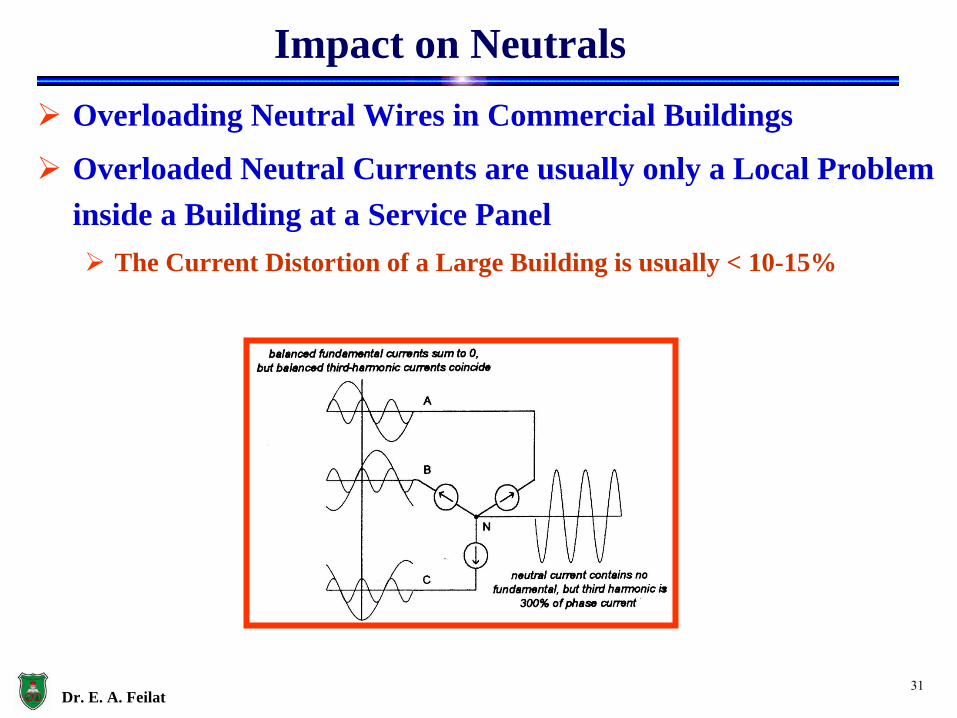
Overloading Neutral Wires in Commercial Buildings
Overloaded Neutral Currents are usually only a Local Problem inside a Building at a Service Panel
The Current Distortion of a Large Building is usually < 10-15%
31Dr. E. A. Feilat

32Dr. E. A. Feilat
Impact on Neutrals

SMPS Current & Spectrum
•
Short Pulses Current•
Very high 3rd Current Harmonic (65%)
•
Overloading of Neutral Conductors of a 3-Ph System 365%
200% of the Fundamental A-B-C Current
•
New Practice Phase and Neutral Wire or Shared Neutral Wire with 200% rating of the Fundamental
•
Transformer Overheating under a Significant SMPS Load. Derating to 80% of Nameplate KVA
33Dr. E. A. Feilat