tool classification report - texas instruments and tests, a validation suite according to iso 26262...
TRANSCRIPT

Tool Classification Report Page 1 Version 0.8 Copyright @ 2013. Texas Instruments Incorporated
Tool Classification Report for TI C/C++ Compiler Chain
Version 0.8
Tool Classification Report Page 2 Version 0.8 Copyright @ 2013. Texas Instruments Incorporated
Revision History:
Version Date Status Autor Change
0.6 2012-12-17 Presented Slotosch Integrated feedback from TÜV Nord
0.7 2013-04-28 In Progress Slotosch Generalized and prepared for Generation
0.7.1 2013-05-27 In Progress Slotosch Improved EN 50128 compliance
0.8 <generation date>
Generated Generator Tool
Filled Model-dependent parts
0.9 <review> Reviewed <Reviewer> Reviewed and updated
1.0 Final

Tool Classification Report Page 3 Version 0.8 Copyright @ 2013. Texas Instruments Incorporated
Contents
1 Scope of this Document .............................................................................................. 4
2 Glossary ....................................................................................................................... 5
3 Evaluation Method ....................................................................................................... 6
3.1 Standard Requirements .............................................................................................. 9 3.1.1 ISO 26262 Requirements ..................................................................................... 10
3.1.1.1 Planning Tool Usage .................................................................................... 10 3.1.1.2 Tool Evaluation ............................................................................................ 11
3.1.1.3 Tool Qualification ........................................................................................ 12
3.1.1.4 Validity Check .............................................................................................. 12
3.1.1.5 Compliance Check and Confirmation Review ............................................. 12 3.1.2 IEC 61508 ............................................................................................................ 13 3.1.3 DO-178 C and DO-330 ........................................................................................ 13 3.1.4 EN 50128 .............................................................................................................. 14
3.2 Tool Chain Analysis Method ................................................................................... 15
3.2.1 Define List of Tools ............................................................................................. 15 3.2.2 Gather tool application facts and identify use cases............................................. 15 3.2.3 Determine Tool Impact ........................................................................................ 16 3.2.4 Identify Potential Errors ....................................................................................... 16
3.2.4.1 Black Box Error Identification Strategy:...................................................... 17 3.2.4.2 White box Error Identification Strategy: ...................................................... 17
3.2.4.3 Consolidating Potential Errors: .................................................................... 17 3.2.5 Identify and Assign Checks and Restrictions ....................................................... 18
3.2.6 Compute the Tool Confidence Level ................................................................... 19 3.2.7 Document the evaluation results .......................................................................... 19
3.2.7.1 TI Determination .......................................................................................... 19
3.2.7.2 TCL Determination ...................................................................................... 20 3.3 Using the Tool Chain Analyzer ................................................................................ 21
3.3.1 Modeling .............................................................................................................. 21 3.3.2 Validation ............................................................................................................. 22 3.3.3 Review .................................................................................................................. 23 3.3.4 Report generation ................................................................................................. 24
3.4 Using the Qualification Tool .................................................................................... 28
4 Tool Chain Definition ................................................................................................. 28
5 Tool Impact Determination ........................................................................................ 29
6 [generated] ........................................................................ Error! Bookmark not defined.
7 References ............................................................................................................... 135
Tool Classification Report Page 4 Version 0.8 Copyright @ 2013. Texas Instruments Incorporated
1 Scope of this Document
This document is a results report of classifying used tools according to their confidence need during the use of a SW tool chain or parts of a
software tool chain related to a specific tool, e.g. a “Generating Tool Chain”.
The evaluated tool chain TI C/C++ Compiler Chain is used by <Customer> for software development. The content of this document
consists of 4 parts:
1. General description of the evaluation method (see section 3).
2. Definition of the tool chain being evaluated (see section 4). 3. Determination of tool impact (see section 5).
4. Determination of tool confidence (see section 6).
The classification is compatible to ISO26262s tool confidence levels but can also be used in other standards (IEC 61508, DO-330, EN 50128) since
they require to determine the confidence needs for the tools by analyzing the impact of potential tool errors. A detailed tracing of the requirements
are in the tool qualification plans for the tools with qualification need

Tool Classification Report Page 5 Version 0.8 Copyright @ 2013. Texas Instruments Incorporated
2 Glossary
This section defines technical terms used within this document.
Term Definition Check possibility to detect an error
Error in this document used as “potential error”
Error (model)
element
representation of an (potential) error in the model
Feature (model)
element
representation of a function in the model.
Function an elementary or composed function of the tool, that can be
required in one or more use-cases, e.g. load, save, “perform” functions
Qualification environment
TAU and tests, a validation suite according to ISO 26262
Restriction possibility to avoid an error
Safety Guideline Guideline to mitigate some potential errors of the tool.
Modeled as a Check or Restriction, either in an usual UseCase or Feature of the Tool, or in a separate, virtual Feature that can be required (added) by any use case of the
same tool. Safety Guidelines are listed in the tool classification report and applied in the tool safety manual.
software off-line support tool
(IEC 61508)
According to IEC61508-4-3.2.11: software tool that supports a phase of the software development lifecycle and
that cannot directly influence the safety-related system during its run time.
TAU Test Automation Unit: executes tests for the test suite
TD Tool Error Detection (TD) probability for a potential error to
be detected / avoided in a defined process TD1=high detection probability, TD2=medium detection probability,
TD3=low or unknown detection probability
TCL (ISO 26262-8) Tool Confidence Level (ISO 26262): required confidence in
the tool when used in the analyzed tool chain TCL1=low confidence required ,
TCL2=medium confidence required, TCL3=high confidence required1
TCR This Tool Classification Report, also called Tool Criteria Evaluation Report in ISO 26262
Test Single test with result PASS/FAIL/ABORT
Test Directory A directory containing one or more test (directories)
Test (model) element
Representation of a test directory in the model including a test description that specifies it
Test Suite structured set of single tests
Test Plan list of test (directories) to be executed
Tool a development tool according to ISO 26262
1 Of course once the tool with TCL>1 have been qualified, the TCL can be regarded as existing tool confidence for the qualified ASIL rather than required tool confidence.
Tool Classification Report Page 6 Version 0.8 Copyright @ 2013. Texas Instruments Incorporated
Tool Chain a collection of tools, not necessarily forming an input/output chain
Tool classes (IEC 61508-4)
Software off-line support tools are classified into the following tool classes: T1: generates no outputs which can directly or indirectly
contribute to the executable code (including data) of the safety related system
T2: supports the test or verification of the design or executable code, where errors in the tool can fail to reveal defects but cannot directly create errors in the executable
software T3: generates outputs which can directly or indirectly
contribute to the executable code of the safety related system.
Tool Classification determination of the required tool confidence level (ISO26262: TCL or IEC 61508: tool classes)
Tool Evaluation or tool criteria evaluation: see tool classification
Use-Case the purpose of using the tool in development process
Use-Case (model) element
representation of an use-case in the model
Virtual Feature A Feature is called virtual, if it’s virtual attribute is set to true. Virtual Features are modeled in a Tool, but are not
implemented in the tool. They are used to model safety guidelines (documents) and can be added flexible as required features to use cases to denote that the use cases
follow them. Virtual feature do not have errors.
Note that elements, relations and actions from the model that have a formal semantic in the TCA are written in capital and with italic font, e.g.
“Error element”, or “Export -> Excel Review”.
3 Evaluation Method
The safety standards (ISO 26262, IEC 61508, DO-178/DO-330) require
the user to analyze the tools used for the development of safety-critical products. The result of the analysis is a requirement on the reliability of
the tool stated in the tool criteria evaluation report. The confidence is determined by an analysis of the use cases of the tool as
used within the development process. If the tool has an impact on the safety of the product, all potential errors within the used features are
analyzed for how they can be detected or avoided within the process. If
there is no high probability for detecting or avoiding the errors, the tool has to be qualified to ensure the absence of these errors.

Tool Classification Report Page 7 Version 0.8 Copyright @ 2013. Texas Instruments Incorporated
Figure 1: Tool Safety Manual Derivation
The tool safety manual for a tool has to contain the mitigations against all potential tool errors that are considered during tool evaluation. The errors
can be grouped into the three classes (see Figure 1): Potential errors in unused features (green in Figure 1)2: Using these
features is prohibited in the tool safety manual (yellow in Figure 1). Potential errors with mitigations: detections and restrictions (yellow
in Figure 1): These mechanisms are described in the tool safety manual.
Remaining potential errors (red in Figure 1): Demonstrating their absence has to be the goal of the tool qualification (tool qualification
plan). The tool qualification report possibly shows some concrete errors that are instances of the potential error classes. The
qualification report contains proposed workarounds for these
concrete errors that have to be part of the safety manual (yellow in Figure 1).
The tool safety manual therefore has to contain the following information: Allowed features and configurations of the tool.
For potential errors that might occur in required features and that are not excluded by tool qualification: Requirements to apply checks
and restrictions to mitigate potential tool errors. Workarounds for known bugs and errors found during qualification.
Other information required by the standards to identify the tool exactly (version, configuration, etc.).
2 Note that the analysis of potential errors in unused functions is not required, but the features need to be identified.

Tool Classification Report Page 8 Version 0.8 Copyright @ 2013. Texas Instruments Incorporated
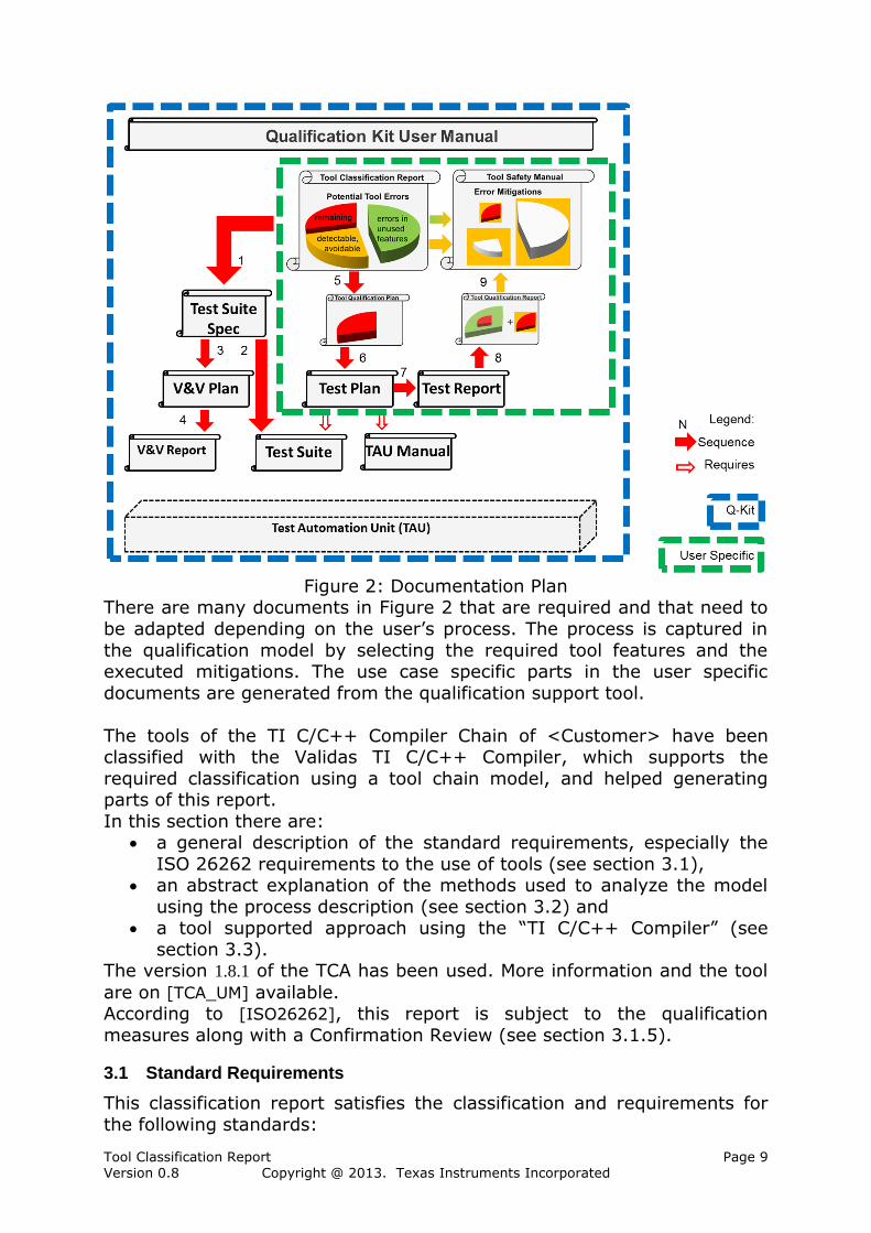
The tool qualification plan has to ensure that the identified potential errors
of the TI C/C++ Compiler Chain which are not detectable / avoidable cannot occur. This is done by applying a validation suite in a systematic
way that shows the absence of these potential errors.
If tools from the TI C/C++ Compiler Chain shall be qualified using validation we have to provide the following documents:
Test Plan: specifies the required test cases for execution Test Report: contains the test results
Test Automation Unit Manual: contains instructions to execute the planned tests cases correctly
Test suite validation and verification documents (plan and report): to ensure that the test suite shows the absence of the potential
errors if passed successfully The documents that depend on the model are typed using italic font.
In the case that the model and the validation suite needs to be extended and new test cases need to be produced and validated, the following
documents are required or need to be extended: Test specifications including a test strategy to show the absence of
the potential errors.
Test suite V&V plan & report The test suite needs validation against the implementation using a review
and a verification that they run correctly on the selected target. This quality process creates the confidence into the effectiveness of the test
suite. The V&V documents for the test suite are contained in the qualification kit to demonstrate the confidence to the user. If the test suite
is extended these documents shall also be extended. Figure 2 shows the relation between the documents and their variability,
i.e. which are constant and which depend on the use case.
Tool Classification Report Page 9 Version 0.8 Copyright @ 2013. Texas Instruments Incorporated
Figure 2: Documentation Plan
There are many documents in Figure 2 that are required and that need to
be adapted depending on the user’s process. The process is captured in
the qualification model by selecting the required tool features and the executed mitigations. The use case specific parts in the user specific
documents are generated from the qualification support tool.
The tools of the TI C/C++ Compiler Chain of <Customer> have been classified with the Validas TI C/C++ Compiler, which supports the
required classification using a tool chain model, and helped generating parts of this report.
In this section there are: a general description of the standard requirements, especially the
ISO 26262 requirements to the use of tools (see section 3.1), an abstract explanation of the methods used to analyze the model
using the process description (see section 3.2) and a tool supported approach using the “TI C/C++ Compiler” (see
section 3.3). The version 1.8.1 of the TCA has been used. More information and the tool
are on [TCA_UM] available. According to [ISO26262], this report is subject to the qualification
measures along with a Confirmation Review (see section 3.1.5).
3.1 Standard Requirements
This classification report satisfies the classification and requirements for
the following standards:

Tool Classification Report Page 10 Version 0.8 Copyright @ 2013. Texas Instruments Incorporated
ISO 26262, see Section 3.1.1,
IEC 61508, see Section 3.1.2, DO-178 C and DO-330, see Section 3.1.3 and
EN 50128, see 3.1.4.
3.1.1 ISO 26262 Requirements
The ISO 26262-8 recommends various steps and documents in order to
establish “Confidence in the use of software tools” (see Fig 1): Planning Tool Usage, see ISO-26262-8-11.4.4 and section 3.1.1.1
Tool Evaluation, see ISO-26262-8-11.4.5 and section 3.1.1.2, Tool Qualification, see ISO-26262-8-11.4.6 and section 3.1.1.3,
Validity Check, see ISO-26262-8-11.4.2 and section 3.1.1.4and Compliance Check and Confirmation Review, see ISO-26262-8-
11.4.3, 11.4.10 and section 3.1.1.5.
This classification report is the required “Tool Criteria Evaluation Report”, which is the result of the step “Tool Evaluation”. Note in this document the
Tool Criteria Evaluation Report is called “Tool Classification Report”. In order to define the context of this work more clearly the other steps are
shortly explained as well
Fig 1: ISO 26262-8 “Confidence in use of software tools”
3.1.1.1 Planning Tool Usage
Tool Classification Report Page 11 Version 0.8 Copyright @ 2013. Texas Instruments Incorporated
All tools to be used for the development of a safety related product need
to be planned first (ISO 26262-8 11.4.4, ISO 26262-6 5.5.4). The following information are used for classifying tools:
Identification and version,
Description of the tool, e.g. reference to a user manual, Used configuration(s),
Use cases with the in- and outputs and If needed qualification methods.
These information and other information required by ISO (see Fig 1) can be included in one or many documents, e.g. the so called Tool Application
Guide.
3.1.1.2 Tool Evaluation
In the tool evaluation the usage information is analyzed and a tool confidence level for the tool is determined. The result of the tool
evaluation is a tool criteria evaluation report, which must contain the information shown in the figure above (see Fig 1).
To determine the tool confidence level for a tool the ISO 26262-8 requires
executing the following two steps: 1. Determine the tool impact (TI) and
2. Determine the Tool Error Detection (TD).
The TCL is determined from these both values.
According to ISO 26262-8 11.4.5.2, the Tool Impact means: “the
possibility that a malfunction of a particular software tool can introduce or fail to detect errors in a safety-related item or element being developed.
- TI1 shall be selected when there is an argument that there is no
such possibility; - TI2 shall be selected in all other cases”.
Tools with TI1 have a low confidence need, e.g. TCL1, and do not need to
be qualified.
For all tools with possible impact (TI2) all use cases have to be analyzed
with the help of the potential errors and their detectability (TD: “Tool Error Detection”). All the use cases of the tool and their potential errors must be
considered and if possible measures that can detect or prevent these errors need to be assigned. For each measure a qualitative tool error
detection (TD) probability has to be assigned: TD=1 if the probability to detect or prevent the error is HIGH,
TD=2 if the probability to detect or prevent the error is MEDIUM and TD=3 in all other cases (LOW or unknown probability).
If several detection or prevention possibilities are available for one error the one with the best detection/prevention probability can be used. In
Tool Classification Report Page 12 Version 0.8 Copyright @ 2013. Texas Instruments Incorporated
case of multiple potential errors for one tool or use case the one with the
worst detection or prevention probability determines the TD for the tool or use case.
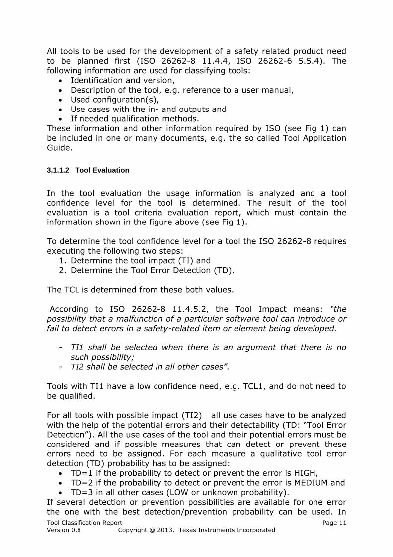
If the TI and TD level has been estimated the required tool confidence
level is completely determined by ISO 26262 according to the following table (see Fig 2).
TD1 TD2 TD3
TI1 TCL1 TCL1 TCL1
TI2 TCL1 TCL2 TCL3
Fig 2: Tool Confidence Levels according to ISO 26262
Tools with TCL 1 are used so that they have a low confidence need and
thus require no qualification.
3.1.1.3 Tool Qualification
Tools with TCL2 or TCL3 need to be qualified. Depending on the
automotive safety integrity level (ASIL) of the item being developed and the tool confidence level the ISO 26262 recommends qualification
methods. For ASIL D the ISO 26262 recommends “Tool Validation” or “Development of the tool according to a safety standard” as qualification
methods. The result of an ASIL decomposition can be taken for the tools only if the decomposed parts are developed with different tool chains.
The goal of tool qualification is to show the absence of the potential errors
identified during the tool evaluation. The result of tool qualification is a tool qualification report, which must contain the information shown in the
figure above (see Fig 1).
3.1.1.4 Validity Check
Classifications of tools and qualification of tools from other projects can be
reused. In both cases, the validity of the assumptions about the use cases and potential errors needs to be checked for the current project (see
[ISO26262] 8-11.4.2).
3.1.1.5 Compliance Check and Confirmation Review
For each used tool must be guaranteed that it fits to the configuration and the version which was used for the classification. Particularly no functions
and variants which were not classified may be applied. The measures considered against potential errors in the classification must be executed
in concrete development process (see [ISO26262] 8-11.4.10). From ASIL B there must be a “Confirmation Review” that confirms, that
The TCL was determined correctly and The required qualification measures for the tool fit to the required
confidence, i.e. demonstrate the absence of the critical, potential errors.
Tool Classification Report Page 13 Version 0.8 Copyright @ 2013. Texas Instruments Incorporated
3.1.2 IEC 61508
The IEC 61508, see [61508] has a tool classification that does not depend
on the use cases of the tools and the potential errors and the measures to detect them.
Part 4, Section 3.2.11 defines:
software off-line support tool as software tool that supports a phase of the software development lifecycle and that cannot directly influence the
safety-related system during its run time. Software off-line tools may be divided into the following classes:
T1: generates no outputs which can directly or indirectly contribute to the executable code (including data) of the safety related system;
T2: supports the test or verification of the design or executable code, where errors in the tool can fail to reveal defects but cannot
directly create errors in the executable software T3: generates outputs which can directly or indirectly contribute to
the executable code of the safety related system
Part 3, Section 7.4.4.5 requires:
An assessment shall be carried out for offline support tools in classes T2 and T3 to determine the level of reliance placed on the tools, and the
potential failure mechanisms of the tools that may affect the executable software. Where such failure mechanisms are identified, appropriate
mitigation measures shall be taken.
This is satisfied by the analysis the ISO 26262 requires for all relevant tools and that is documented in this classification report.
3.1.3 DO-178 C and DO-330
The DO-330, see [DO330] is a standard for tool qualification that is required to be applied from DO-178 C, see [DO178C]. The DO-178C
classifies the tools into the following three classes (see 12.2.2: Determination of the tool qualification level):
Criteria 1: A tool whose output is part of the airborne software and thus could insert an error.
Criteria 2: A tool that automates verification process(es) and thus
could fail to detect an error, and whose output is used to justify the elimination or reduction of:
o Verification process(es) other that automated by the tool, or o Development process(es) that could have an impact on the
airborne software Criteria 3: A tool that within the scope of its intended use could fail
to detect an error.
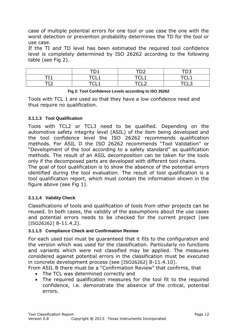
From this classification and the software risk level a so called tool qualification level (TQL) is computed using the table in Figure 3. TQL-1 is
the most rigorous level, while TQL-5 has the least requirements.
Tool Classification Report Page 14 Version 0.8 Copyright @ 2013. Texas Instruments Incorporated
Figure 3: Determination of TQL in DO-178C, Table 12-1
The DO-330 specifies the processes that shall be applied to qualify the tools depending on the TQL.
The DO-330 requires for all levels to have a plan for software aspects of certification (PSAC) that contains the impact of the tool in the software life
cycle (see 10.1.1.a) and the certification credit it claims during automation in the process (see 10.1.1.b). The verification of the tool in
the operational environment should “demonstrate the coverage of the
processes intended to be eliminated, reduced, or automated by the use of the tool” (see 6.2.2.b).
This report contains the results of the tool classification according to the
use cases and determines the required confidence by analyzing the impact of the potential errors. Hence it satisfies the above requirements from the
DO-330 / DO 178 C.
Furthermore the TQL can be reduced based on this tool classification report if the potential tool errors have high detection probabilities, since
the DO-330 contains the following statement (FAQ D.2): To reduce a tool’s qualification level, the reduction needs to be justified by performing
a tool use and impact analysis. This analysis needs to evaluate the overall use of the tool in the development process and its impact on the software
being produced.
Therefore this classification report is an essential contribution to all qualification levels from DO-178 C and DO-330 and in addition can be
used to reduce the tool qualification level.
3.1.4 EN 50128
Similar to IEC 61508 (see Section 3.1.2) the EN 50128, see [EN50128]
defines in Sections 3.1.42, 3.1.43, 3.1.44 the following tool classes: tool class T1
generates no outputs which can directly or indirectly contribute to the executable code (including data) of the software
tool class T2 supports the test or verification of the design or executable code,
where errors in the tool can fail to reveal defects but cannot directly create errors in the executable software
Tool Classification Report Page 15 Version 0.8 Copyright @ 2013. Texas Instruments Incorporated
tool class T3
generates outputs which can directly or indirectly contribute to the executable code (including data) of the safety related system
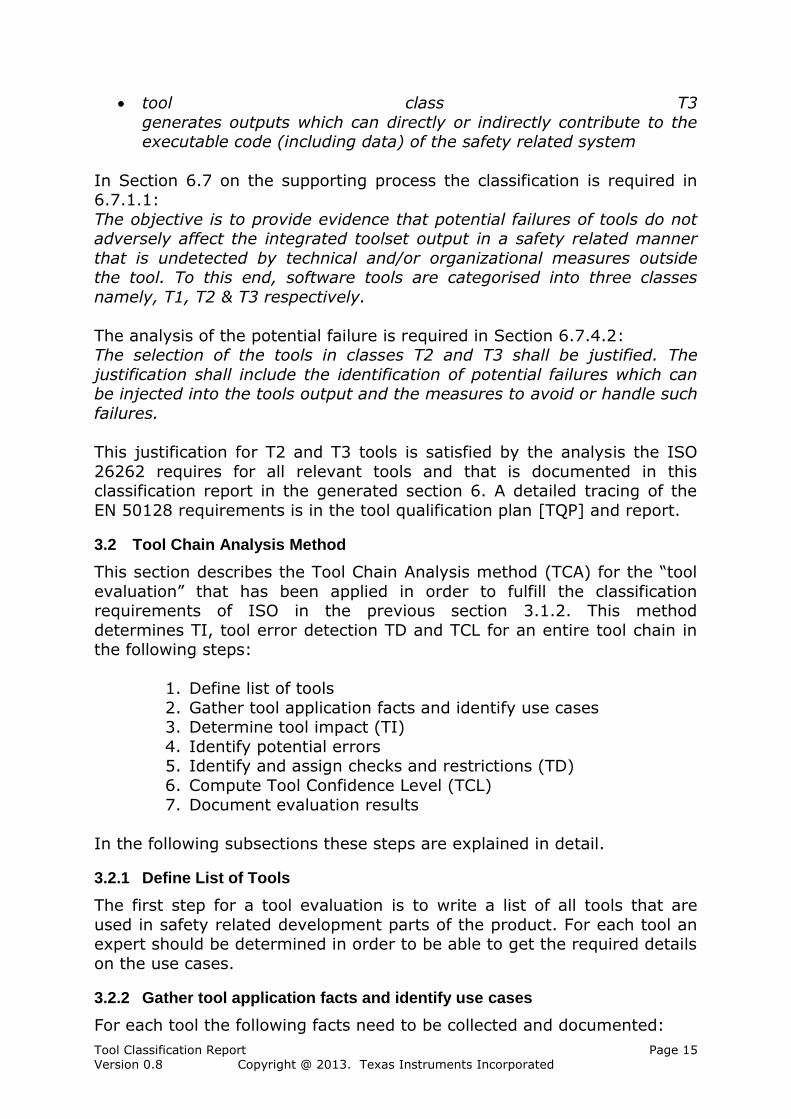
In Section 6.7 on the supporting process the classification is required in 6.7.1.1:
The objective is to provide evidence that potential failures of tools do not adversely affect the integrated toolset output in a safety related manner
that is undetected by technical and/or organizational measures outside the tool. To this end, software tools are categorised into three classes
namely, T1, T2 & T3 respectively.
The analysis of the potential failure is required in Section 6.7.4.2: The selection of the tools in classes T2 and T3 shall be justified. The
justification shall include the identification of potential failures which can be injected into the tools output and the measures to avoid or handle such
failures.
This justification for T2 and T3 tools is satisfied by the analysis the ISO
26262 requires for all relevant tools and that is documented in this classification report in the generated section 6. A detailed tracing of the
EN 50128 requirements is in the tool qualification plan [TQP] and report.
3.2 Tool Chain Analysis Method
This section describes the Tool Chain Analysis method (TCA) for the “tool
evaluation” that has been applied in order to fulfill the classification requirements of ISO in the previous section 3.1.2. This method
determines TI, tool error detection TD and TCL for an entire tool chain in the following steps:
1. Define list of tools
2. Gather tool application facts and identify use cases 3. Determine tool impact (TI)
4. Identify potential errors 5. Identify and assign checks and restrictions (TD)
6. Compute Tool Confidence Level (TCL)
7. Document evaluation results
In the following subsections these steps are explained in detail.
3.2.1 Define List of Tools
The first step for a tool evaluation is to write a list of all tools that are
used in safety related development parts of the product. For each tool an expert should be determined in order to be able to get the required details
on the use cases.
3.2.2 Gather tool application facts and identify use cases
For each tool the following facts need to be collected and documented:
Tool Classification Report Page 16 Version 0.8 Copyright @ 2013. Texas Instruments Incorporated
Tool versions,
Configuration (it could depend of the installation, Used features,
If mentioned in the tool description:
o potential errors of the tool/features, o Measures for prevention and detection of these and other
possible errors.
A use case contains at least the following information: Title: needed to identify the use case.
Description, If necessary the used tool features,
Inputs and Outputs.
The individual tools are integrated over the input and output artifacts to a
tool chain. It is important to give the artifacts consistent names in order to avoid confusion and duplication.
A convenient representation of the input/output relationships of use cases
in a tool chain is the so called tool artifact matrix. It represents all artifacts in lines and all the use cases of the tool in columns. The entries in
the matrix indicate what actions the use cases executed on the artifacts (Read/Write).
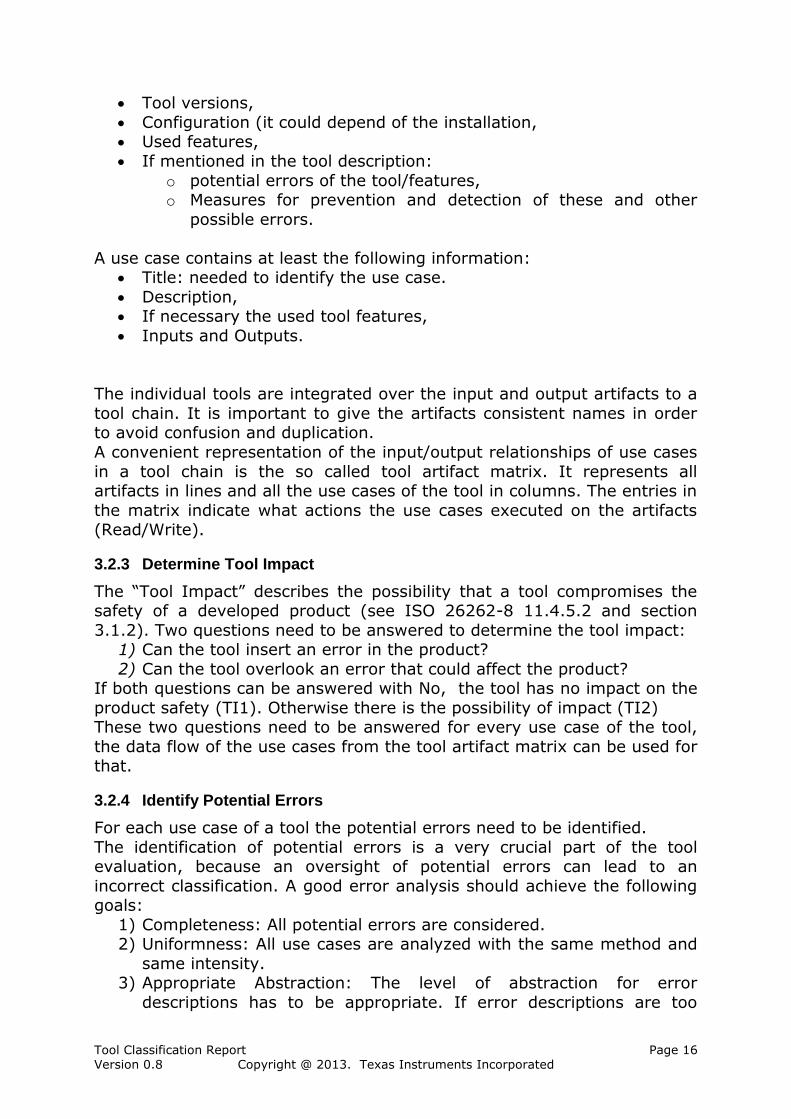
3.2.3 Determine Tool Impact
The “Tool Impact” describes the possibility that a tool compromises the safety of a developed product (see ISO 26262-8 11.4.5.2 and section
3.1.2). Two questions need to be answered to determine the tool impact: 1) Can the tool insert an error in the product?
2) Can the tool overlook an error that could affect the product? If both questions can be answered with No, the tool has no impact on the
product safety (TI1). Otherwise there is the possibility of impact (TI2) These two questions need to be answered for every use case of the tool,
the data flow of the use cases from the tool artifact matrix can be used for that.
3.2.4 Identify Potential Errors
For each use case of a tool the potential errors need to be identified.
The identification of potential errors is a very crucial part of the tool evaluation, because an oversight of potential errors can lead to an
incorrect classification. A good error analysis should achieve the following goals:
1) Completeness: All potential errors are considered. 2) Uniformness: All use cases are analyzed with the same method and
same intensity. 3) Appropriate Abstraction: The level of abstraction for error
descriptions has to be appropriate. If error descriptions are too
Tool Classification Report Page 17 Version 0.8 Copyright @ 2013. Texas Instruments Incorporated
abstract, assigning suitable checks becomes very difficult. If error
descriptions are too concrete, some errors might not be covered.
In order to achieve these goals two strategies are used to analyze each
use cases of a tool (see [SAFECOMP12]): 1. An artifact oriented Black Box approach (see section 3.2.4.1)
2. A functional White Box approach (see section 3.2.4.2).
The errors found thereby should be consolidated for the specific places of occurrence. This is described in section 3.2.4.3.
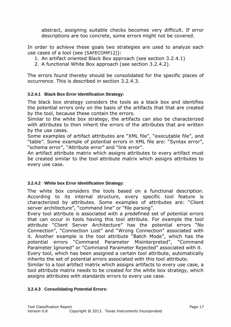
3.2.4.1 Black Box Error Identification Strategy:
The black box strategy considers the tools as a black box and identifies the potential errors only on the basis of the artifacts that that are created
by the tool, because these contain the errors. Similar to the white box strategy, the artifacts can also be characterized
with attributes to then inherit the errors of the attributes that are written by the use cases.
Some examples of artifact attributes are “XML file”, “executable file”, and “table”. Some example of potential errors in XML file are: “Syntax error”,
“schema error”, “Attribute error” and “link error”. An artifact attribute matrix which assigns attributes to every artifact must
be created similar to the tool attribute matrix which assigns attributes to
every use case.
3.2.4.2 White box Error Identification Strategy:
The white box considers the tools based on a functional description. According to its internal structure, every specific tool feature is
characterized by attributes. Some examples of attributes are: “Client server architecture”, “command line” or “file parsing”.
Every tool attribute is associated with a predefined set of potential errors that can occur in tools having this tool attribute. For example the tool
attribute “Client Server Architecture” has the potential errors “No Connection”, “Connection Lost” and “Wrong Connection” associated with
it. Another example is the tool attribute “Batch Mode”, which has the potential errors “Command Parameter Misinterpreted”, “Command
Parameter Ignored” or “Command Parameter Rejected” associated with it. Every tool, which has been assigned a certain tool attribute, automatically
inherits the set of potential errors associated with this tool attribute. Similar to a tool artifact matrix which assigns artifacts to every use case, a
tool attribute matrix needs to be created for the white box strategy, which
assigns attributes with standards errors to every use case.
3.2.4.3 Consolidating Potential Errors:

Tool Classification Report Page 18 Version 0.8 Copyright @ 2013. Texas Instruments Incorporated
After the white box and black box error identification strategies have been
applied one typically ends up with large sets of potential errors for each use case of a tool. To reach the goal of an “Appropriate Abstraction” of the
set of potential errors, the errors can be summarized in use case specific
equivalence classes of errors that are detectable or avoidable with common measures. When an error subsumes another error, it is sufficient
to define some measure for the subsuming errors. The subsumed errors can be hidden, but the subsumption information must be retained to
protect (ensure) the argumentation. The granularity of the errors should be as rough as possible, in order to
define as few measure of detection and avoidance. On the other hand, the granularity should be so fine, that the measures can be applied concretely
and simply. Overlapping errors should be summarized, if there is no very simple
measure for a class. For example the errors “Command Parameter Misinterpreted” and “Command Parameter Ignored” can be subsumed by a
more general error “Command Parameters Violated”.
3.2.5 Identify and Assign Checks and Restrictions
After the error identification each use case is assigned a set of potential
errors. Now, one has to identify detection- (checks) or avoidance measures (restrictions) for these errors. According to ISO 26262 there are
two measures arts: Checks, which detect errors that have occurred,
Restrictions, which avoid the occurrence of errors.
Measures against potential errors are also modeled in the tool chain and have a qualitative probability (high/medium/low) of detection or
avoidance of allocated error(s). The measures can be used either directly on the tool in which the potential errors could occur, or in another tool. In
the latter case, of course, a corresponding data flow (over artifact connections) must exist between the two tools. The information flow of
these connections depends on the nature of the measure. For checks, the checking tool must use a deficient output artifact as input artifact. The
checking tool will then be executed in the tool chain after the tool with the
potential errors. However, restrictions need to sink in before the use of the potentially deficient tool.
For example, a “syntax check” of a compiler can detect some potential errors of a code generator. In this case, the two tools are connected to the
artifact code generated by the generator and read by the compiler. A specification of a code generation configuration (in the tool) or the
application of a code checker (another tool) on the model that generates the code could be measures of avoidance of some potential errors of the
code generator. Some measure will surely be applied (e.g. the syntax check of the
compiler). Other measures may also be omitted. The latter are marked as assumptions in the tool chain analysis and must be explicitly pinned in the

Tool Classification Report Page 19 Version 0.8 Copyright @ 2013. Texas Instruments Incorporated
development process, e.g. by creating scripts/requirements to be kept.
Plus, all the assumptions under which the tool classification is created should be indicated. This is particularly important when the analyzed tool
chains are reused in other projects.
3.2.6 Compute the Tool Confidence Level
After the assignment of checks and restrictions to errors and the estimation of detection probabilities, the tool error detection levels (TD)
and also the tool confidence level (TCL) can be computed automatically for entire use cases, tools or tool chains. The following rules are used:
TD (Errors): the probability that checks and restrictions for an error reach for an error is the maximum of the probabilities of the
assigned and active/achievable checks and restrictions. TD (Use cases): the probability that checks and restrictions reach
for all potential errors in a use case is the minimum of the probabilities of the errors appearing potentially in it.
TD (Tool): the probability that checks and restrictions reach for all potential errors in a tool is the minimum of the probabilities of all
the use cases in the tool. The tool Confidence Level results from the so determined probabilities
according to ISO 26262 (see Fig 2) as follows:
TD=High => TCL 1 TD=MEDIUM => TCL 2
TD=LOW => TCL3
The TCL can be computed in two ways: 1) With the use of assumptions,
2) Without the use of assumptions. In both calculations only the used use cases are committed. Particularly if
reusable functions models of tools are available (when indicated with high TCL), only the functions that are used in the use cases are considered.
3.2.7 Document the evaluation results
The evaluation results for each tool and the entire tool chain need to be documented in the tool criteria evaluation report, in particular the TCL and
the thoughts it results from. It begins with the Tool Impact documentation (TI) and contains all the needed information for computing the TCL. The
analysis must be confirmed in a “Confirmation Review” that must confirm
the argumentation.
3.2.7.1 TI Determination
For the determination of the tool impact two questions need to be
answered: “Can an error occur in the product?” and
“Can an error be ignored in the product?”. If one of the questions is answered with Yes, then there is a possible
impact. The question must be answered on the basis of the data flow of
Tool Classification Report Page 20 Version 0.8 Copyright @ 2013. Texas Instruments Incorporated
the use cases and tools. If no impact can be shown the decision must be
supported with an informal argument. For example, typical justifications for the editor are that the inputs are controlled visually (WYSIWYG) and
the errors would be noticed. The decisions must be documented, this
occurs in chapter 5.
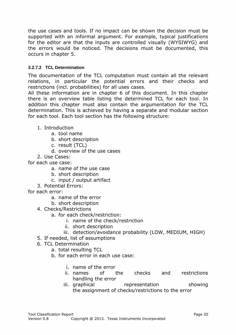
3.2.7.2 TCL Determination
The documentation of the TCL computation must contain all the relevant
relations, in particular the potential errors and their checks and restrictions (incl. probabilities) for all uses cases.
All these information are in chapter 6 of this document. In this chapter there is an overview table listing the determined TCL for each tool. In
addition this chapter must also contain the argumentation for the TCL determination. This is achieved by having a separate and modular section
for each tool. Each tool section has the following structure:
1. Introduction a. tool name
b. short description c. result (TCL)
d. overview of the use cases 2. Use Cases:
for each use case:
a. name of the use case b. short description
c. input / output artifact 3. Potential Errors:
for each error: a. name of the error
b. short description 4. Checks/Restrictions
a. for each check/restriction: i. name of the check/restriction
ii. short description iii. detection/avoidance probability (LOW, MEDIUM, HIGH)
5. If needed, list of assumptions 6. TCL Determination
a. total resulting TCL
b. for each error in each use case:
i. name of the error ii. names of the checks and restrictions
handling the error iii. graphical representation showing
the assignment of checks/restrictions to the error
Tool Classification Report Page 21 Version 0.8 Copyright @ 2013. Texas Instruments Incorporated
Note: The computed TCL requires that the considered mitigation
mechanisms are carried out by the users of the tools. This can be ensured by respecting tool safety manuals that contain the mitigations.
3.3 Using the TI C/C++ Compiler
The classification of the tool chain TI C/C++ Compiler Chain of <Customer> described above is supported by a Validas tool called “TI
C/C++ Compiler” (TCA). The TCA automatically determines the TCL of all tools, based on a formal model of tool chain and generates a report (see
chapter 6). The tool is available for free and can be obtained from [TCA].The created model for TI C/C++ Compiler Chain was validated
through a consistency check and a review of the user in <Customer>before the creation of this report. Therefore the following
steps are needed for a new generation of this report: Model adaptation (see section 3.3.1),
Consistency check of the model (see section 3.3.2), Model review (see section 3.3.3) and
Report generation (see section 3.3.4).
The steps are described in the following sections. Details can be found in
[TCA_UM] and can be learned in a training course on the tool.
3.3.1 Modeling
The model of the tool chain TI C/C++ Compiler Chain consists of an element “ToolChain” that contains an element “Tool” for every tool of the
tool chain. It also contains the used artifacts that show the relation between the tools.
For each tool, the use cases are modeled, in which the tool is used in <Customer>. Potential errors, checks and restrictions are assigned with
their probabilities to each use case. The error elements are related to the checks and the restrictions that detect or avoid them. The TD and the TCL
are computed according to ISO 26262 (see section 3.1.2 and 3.2.6) with the probabilities of the assigned checks and restrictions. If several use
cases use the same functionalities in a tool, then it makes sense to model these tool functionalities as features. Since each feature can be used by
several use cases, it is possible to avoid redundant error definitions as the
errors are not individually defined for each use case, but they are assigned the features, in which they can occur. The errors of the features
can be reused. They are inferred to the use cases and represented as “Inferred Error” elements.
The tool chain model can be used in different variants or can be extended to new variants. The variants are managed in the element “ToolChain”.
The elements (tools, use cases, artifacts) that are not considered in all variants have a link to the variants in which they are considered.
The reviewed errors are important for the quality of the analysis. Therefore, the tools support a systematic process to identify potential
Tool Classification Report Page 22 Version 0.8 Copyright @ 2013. Texas Instruments Incorporated
errors (black box and white box). These are assigned to the artifacts and
the use cases through attributes. The attributes are listed in the ToolChain model under “DefaultErrorAttributes”. Errors that derive from attributes
are called “Derived Errors” and can be disabled from the model, but before
they must be listed in specific errors (list of “subsumed errors”) for the use cases.
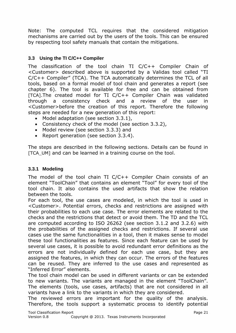
The source of the modeled information in the TCA is different. The model integrates information from the process, the used tools and the systematic
error model and generates the reports with the TCLs (see Fig 3).
Fig 3: Validas TI C/C++ Compiler and its environment
The model can be directly created in the tool. Some information can also
be imported via an Excel interface (e.g. the Tool Artifact Matrix).
3.3.2 Validation
There are two steps for the model validation: 1. Consistence check of the model and
2. Textual and technical check (review).
The review is described in section 3.3.3. The model validation is started by right clicking on the model and selecting the feature “Validate” (see Fig 4).
Then, all the tests described in [TCA_UM], chapter 8.5 are executed on the selected model element.

Tool Classification Report Page 23 Version 0.8 Copyright @ 2013. Texas Instruments Incorporated
Fig 4: validation start in TCA
No more errors should occur. The following tests could be exceptions (see
[TCA_UM] for detailed descriptions of the checks): Deactivated (checks deactivated elements): this condition may be
violated only by tools that are modelled in this chain, but can not be
used (for example to analyse a variant of a tool chain). UseCaseComplete (checks if the use case contains an error model):
this condition may be violated only by use cases, which are carried out by people (e.g. a review). . In this case the incompleteness
message which indicates missing errors is acceptable. In the present tool chain TI C/C++ Compiler Chain no other “syntactic
violations” exist.
3.3.3 Review
The review of the model ensures the textual and technical correctness of the model in the first instance. This is especially necessary if the modeler
and the assistants who carry out the test are different people, e.g. model creation by the Validas employees or central departments for specific
development projects. The review can be done in the model or in excel.
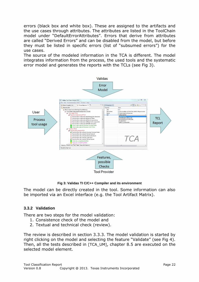
An excel table is generated, that generates the following columns for each
error, check and restriction in all use cases/tools: Name of the reviewer
Is the probability correctly slected/computed (OK/NOK)? Is the check/restriction performed (true/false)?
Comment, e.g. are there further elements? Or reasons for differences.
The lines in the table are grouped by tools and use cases. The excel export is generated by right-clicking on the tool chain element and
selecting the menu item Export -> Excel review (see Fig 5).
Tool Classification Report Page 24 Version 0.8 Copyright @ 2013. Texas Instruments Incorporated
Fig 5: Export Review Table
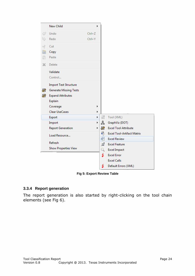
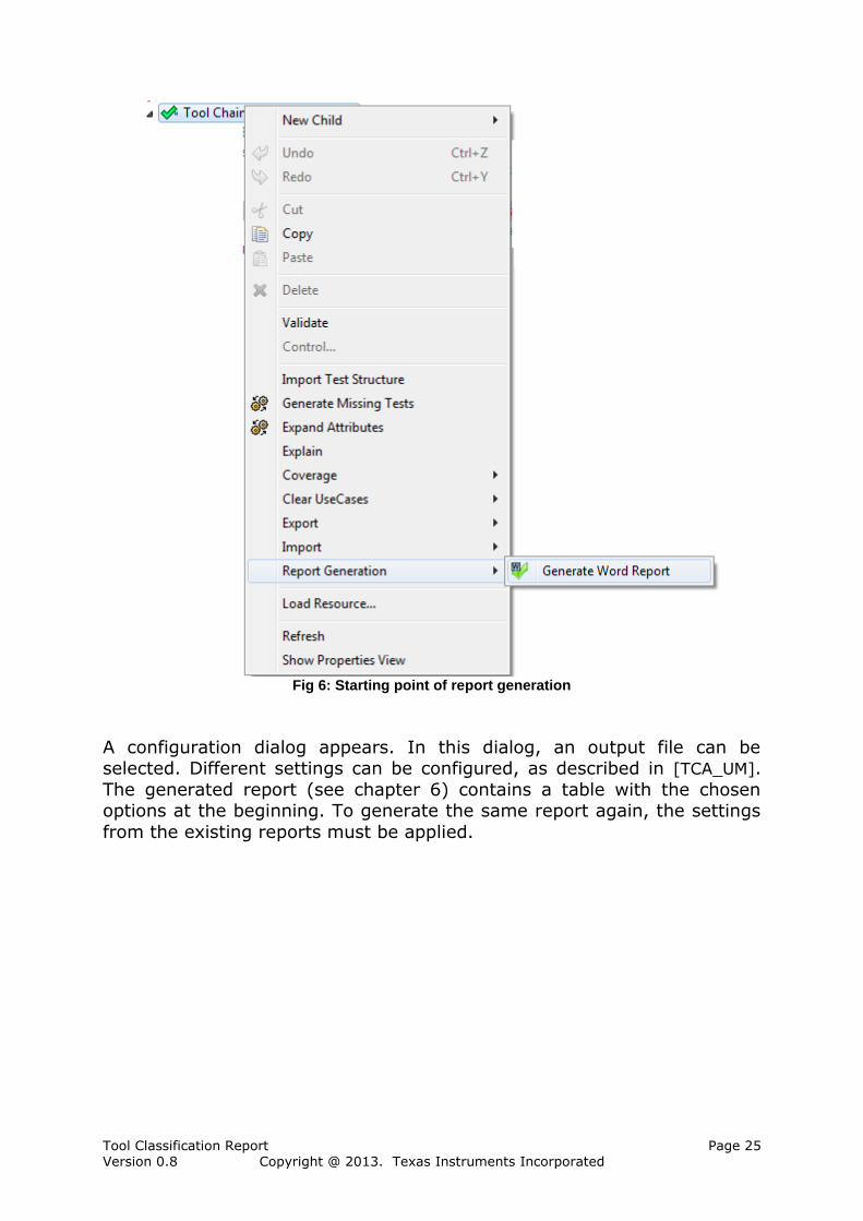
3.3.4 Report generation
The report generation is also started by right-clicking on the tool chain
elements (see Fig 6).
Tool Classification Report Page 25 Version 0.8 Copyright @ 2013. Texas Instruments Incorporated
Fig 6: Starting point of report generation
A configuration dialog appears. In this dialog, an output file can be selected. Different settings can be configured, as described in [TCA_UM].
The generated report (see chapter 6) contains a table with the chosen options at the beginning. To generate the same report again, the settings
from the existing reports must be applied.

Tool Classification Report Page 26 Version 0.8 Copyright @ 2013. Texas Instruments Incorporated
Fig 7: configuration dialog for the report generation
The generated report can contain graphs (e.g. for each analyzed potential error). The exported images use the following conventions:
Elements are coloured according to their criticality (confidence
requirement) with the following conventions:
o Uncritical / HIGH detection probability: green (light grey in
black & white export),
o Medium / MEDIUM detection probability: orange (dark grey in
black & white export),
o Critical / LOW detection probability: red (black in black &
white export).
The criticality of elements is determined as follows:
o Check: detection probability,
o Restriction: avoidance probability,
o Error: error detection probability,
o Use case/feature: Tool Confidence Level (TCL1=green/light
grey, TCL2=orange/dark grey, TCL3=red/black),
o Tool: also TCL (TCL1=green/light grey, TCL2=orange/dark
grey, TCL3=red/black),
o Artifacts are coloured according to their usage in the model:
Green/light grey: read and written artifact,
Orange/dark grey: only written artifact that is not used,
Red/black: artifact that is not read, or written.
When needed, the main element is emphasized with a thick border
(e.g. the considered error).
When it is necessary to distinguish between elements the following
shapes are used:
Tool Classification Report Page 27 Version 0.8 Copyright @ 2013. Texas Instruments Incorporated
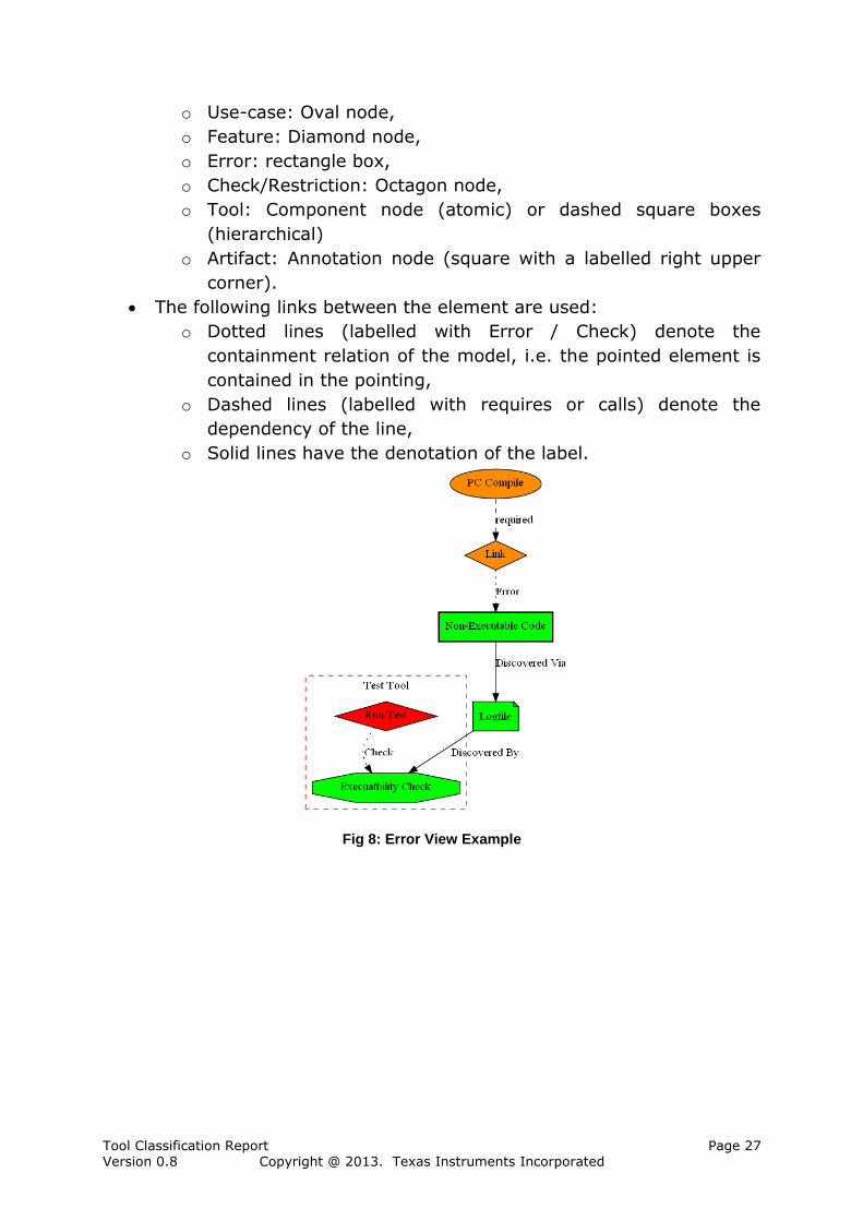
o Use-case: Oval node,
o Feature: Diamond node,
o Error: rectangle box,
o Check/Restriction: Octagon node,
o Tool: Component node (atomic) or dashed square boxes
(hierarchical)
o Artifact: Annotation node (square with a labelled right upper
corner).
The following links between the element are used:
o Dotted lines (labelled with Error / Check) denote the
containment relation of the model, i.e. the pointed element is
contained in the pointing,
o Dashed lines (labelled with requires or calls) denote the
dependency of the line,
o Solid lines have the denotation of the label.
Fig 8: Error View Example

Tool Classification Report Page 28 Version 0.8 Copyright @ 2013. Texas Instruments Incorporated
Fig 9: Error View Example (Black/White)
An example for an image with the above elements is shown above (see
Fig 8 and Fig 9). It explains the error “Non-Executable Code” of a linker which is marked in a rectangle with thick border. This error could appear
in the use case “PC Compiler” and detected by “Test Tool” with a high probability.
3.4 Using the Qualification Tool
Within some qualification kits created from Validas, there is a special
purpose qualification tool that eases the qualification process by A model for the tool with features, potential errors and possible
mitigations Guiding the user throw the qualification process,
Selecting the required features, Selecting the mitigations that can be applied in the process,
Generation of the documents (including this classification report) and
Generation of the tool chain analyzer model (.tca file).
In this case the Tool Chain Analyzer is not necessary and is only an optional tool to extend the qualification kit by new features, new errors
and mitigation measures.
4 Tool Chain Definition
The tool chain model TI C/C++ Compiler Chain was created by Validas
AG, based on process description of the <Customer> and taking into
account feedbacks. The model has been reviewed by the experts with tool responsibilities and thus it is a valid model of the current TI C/C++

Tool Classification Report Page 29 Version 0.8 Copyright @ 2013. Texas Instruments Incorporated
Compiler Chain. The other projects that want to use the existing
classification results have to ensure that: a) the tool chain is used as described (data flow, counter-measures,…),
b) no new tools, features/use cases in particular are added.
Under these circumstances, the model is valid, and the tool confidence level that has been calculated is actually the level of the used tool chain
and the used tools. The conformity of the model and of this report must be checked for each other development projects (as imposed by the ISO
“Confirmation Review” of the TCL und the required qualification measures, see [ISO26262], 8- 11.4.10).
In addition to the generated classification of the tools in this report, the
following information about all used tools have to be determined (e.g. in the Safety Manual of the tool chain or individual tools):
version of the tool (is important in particular for qualified tools, since each tool-related change needs to be re-qualified),
tool configuration(s), tool environment,
maximum risk level (ASIL,SIL or Risk Class) of the tool or any
existing qualifications, description of the features/user manual,
known errors and measures. Particularly the last point is important for a tool management, because the
users must be informed about tools mistakes of qualified tools.
5 Tool Impact Determination
The Tool Impact (TI) of the tool chain TI C/C++ Compiler Chain was
determined as described in section 3.2.3 and 3.2.3.7.1. The Tool Impact is specified with the calculation of the TCL in section 6 under the result
overview and for every tools and every Use-Case separately. An Excel table [TI] from the TCA was generated to get a better view and
to validate the closed impact. In that table a data flow path from and to the artifacts can be analysed near the applied and if necessary the
justified it in the product.
Tool Classification Report Page 30 Version 0.8 Copyright @ 2013. Texas Instruments Incorporated
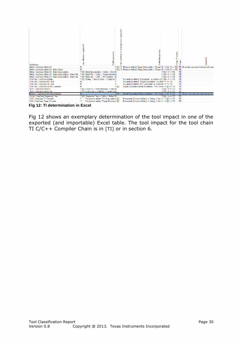
Fig 12: TI determination in Excel
Fig 12 shows an exemplary determination of the tool impact in one of the exported (and importable) Excel table. The tool impact for the tool chain
TI C/C++ Compiler Chain is in [TI] or in section 6.

Tool Classification Report Page 31 Version 0.8 Copyright @ 2013. Texas Instruments Incorporated
6 TCL Details of TI Compiler Tools
This chapter has been generated from the formal tool chain model and contains all relevant
information to determine the TCLs of the used tools.
Table 1 shows the settings and Table 2 shows the active variants with which this document
was generated. For further details of the report creation see section "Report Generation" of the
User Manual.
Setting Value
Compact Report True
With Assumptions Chapters False
Include Subsumes True
Include Images False
Table 1 Settings for this documentation
Variant Settings
Active Variants:
ARM Family
Table 2 Variant Settings
The report starts with an overview of the analysis results, then describes each tool in detail,
including TCL determination, and concludes with an appendix for further information.
ToolChain: TI Compiler Tools
Description:
-None-
TCL Determination:
TCL 3
Use Assumptions:
False
Table 3 ToolChain: TI Compiler Tools
6.1 TCL Result Overview
Table 4 shows the result of the tool evaluation, particulary the tool confidence levels.
Name Tool Impact (TI) Tool
Detection
(TD)
Tool
Confidence
Level (TCL)
Assumptions
Archiver TI 2 (Impact) TD 1
(HIGH)
TCL 1 -
C/C++ Compiler TI 2 (Impact) TD 3
(LOW)
TCL 3 -
Compiler Utilities TI 2 (Impact) TD 2
(MEDIUM)
TCL 2 -
Tool Classification Report Page 32 Version 0.8 Copyright @ 2013. Texas Instruments Incorporated
Hex Converter TI 2 (Impact) TD 2
(MEDIUM)
TCL 2 -
Linker TI 2 (Impact) TD 3
(LOW)
TCL 3 -
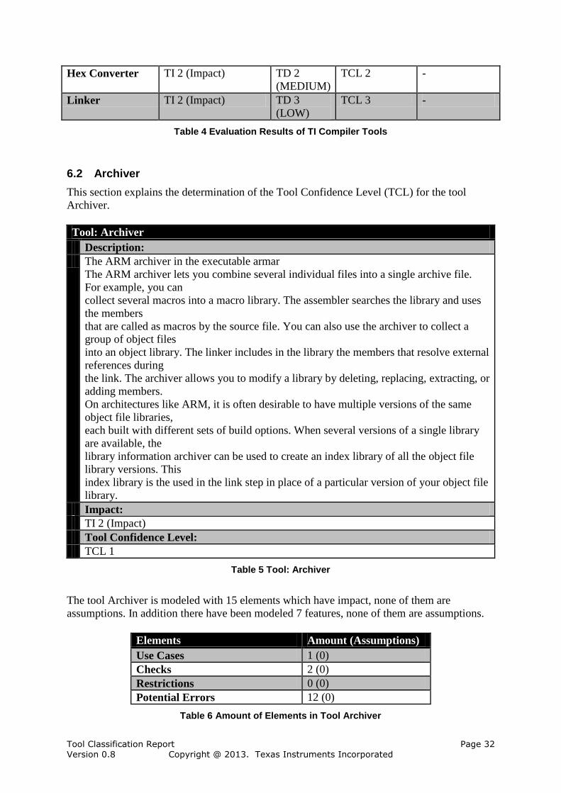
Table 4 Evaluation Results of TI Compiler Tools
6.2 Archiver
This section explains the determination of the Tool Confidence Level (TCL) for the tool
Archiver.
Tool: Archiver
Description:
The ARM archiver in the executable armar
The ARM archiver lets you combine several individual files into a single archive file.
For example, you can
collect several macros into a macro library. The assembler searches the library and uses
the members
that are called as macros by the source file. You can also use the archiver to collect a
group of object files
into an object library. The linker includes in the library the members that resolve external
references during
the link. The archiver allows you to modify a library by deleting, replacing, extracting, or
adding members.
On architectures like ARM, it is often desirable to have multiple versions of the same
object file libraries,
each built with different sets of build options. When several versions of a single library
are available, the
library information archiver can be used to create an index library of all the object file
library versions. This
index library is the used in the link step in place of a particular version of your object file
library.
Impact:
TI 2 (Impact)
Tool Confidence Level:
TCL 1
Table 5 Tool: Archiver
The tool Archiver is modeled with 15 elements which have impact, none of them are
assumptions. In addition there have been modeled 7 features, none of them are assumptions.
Elements Amount (Assumptions)
Use Cases 1 (0)
Checks 2 (0)
Restrictions 0 (0)
Potential Errors 12 (0)
Table 6 Amount of Elements in Tool Archiver
Tool Classification Report Page 33 Version 0.8 Copyright @ 2013. Texas Instruments Incorporated
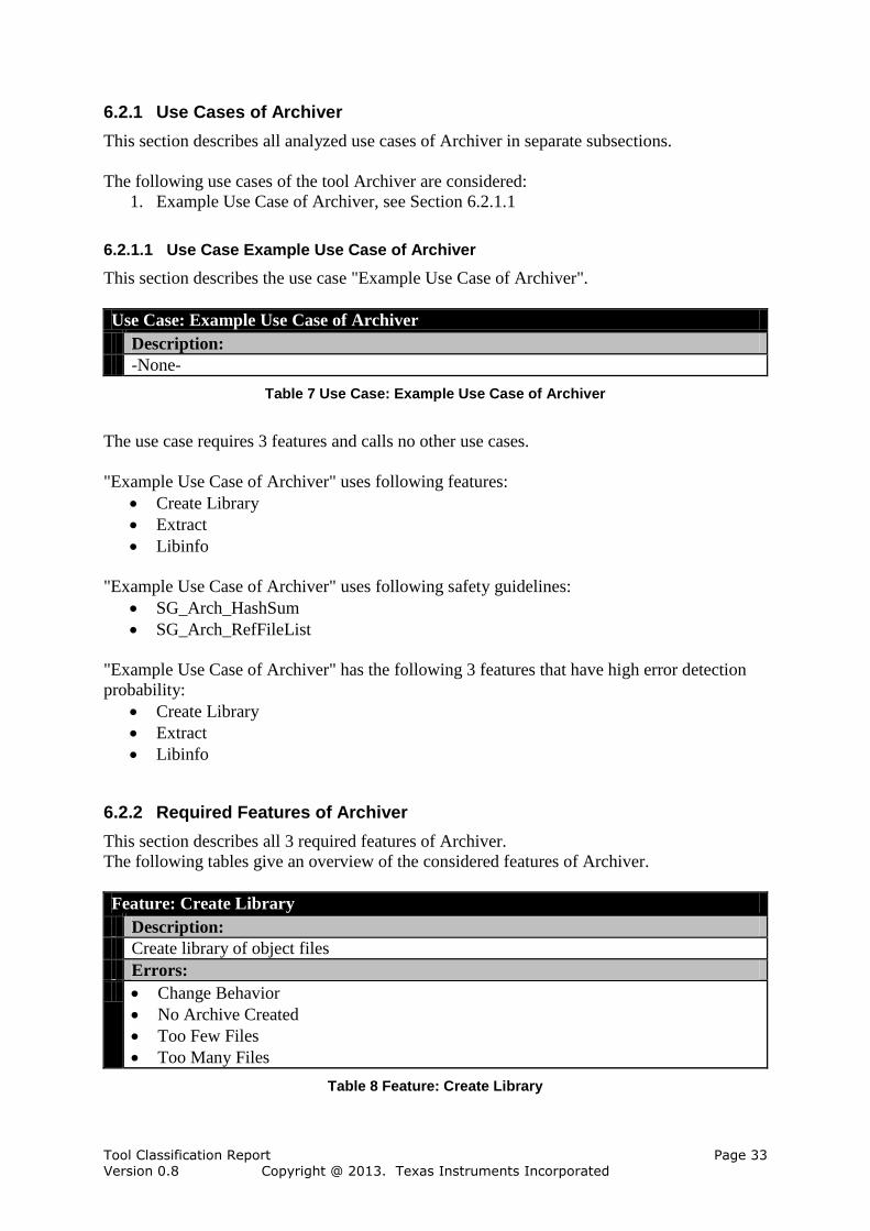
6.2.1 Use Cases of Archiver
This section describes all analyzed use cases of Archiver in separate subsections.
The following use cases of the tool Archiver are considered:
1. Example Use Case of Archiver, see Section 6.2.1.1
6.2.1.1 Use Case Example Use Case of Archiver
This section describes the use case "Example Use Case of Archiver".
Use Case: Example Use Case of Archiver
Description:
-None-
Table 7 Use Case: Example Use Case of Archiver
The use case requires 3 features and calls no other use cases.
"Example Use Case of Archiver" uses following features:
Create Library
Extract
Libinfo
"Example Use Case of Archiver" uses following safety guidelines:
SG_Arch_HashSum
SG_Arch_RefFileList
"Example Use Case of Archiver" has the following 3 features that have high error detection
probability:
Create Library
Extract
Libinfo
6.2.2 Required Features of Archiver
This section describes all 3 required features of Archiver.
The following tables give an overview of the considered features of Archiver.
Feature: Create Library
Description:
Create library of object files
Errors:
Change Behavior
No Archive Created
Too Few Files
Too Many Files
Table 8 Feature: Create Library

Tool Classification Report Page 34 Version 0.8 Copyright @ 2013. Texas Instruments Incorporated
Feature: Extract
Description:
-x
Extract object files from library.
Errors:
Change Behavior
No Files Extracted
Too Few Files
Too Many Files
Table 9 Feature: Extract
Feature: Libinfo
Description:
libinfo tool
Create index library
Errors:
Change Behavior
No Index Created
Too Few Files
Too Many Files
Table 10 Feature: Libinfo
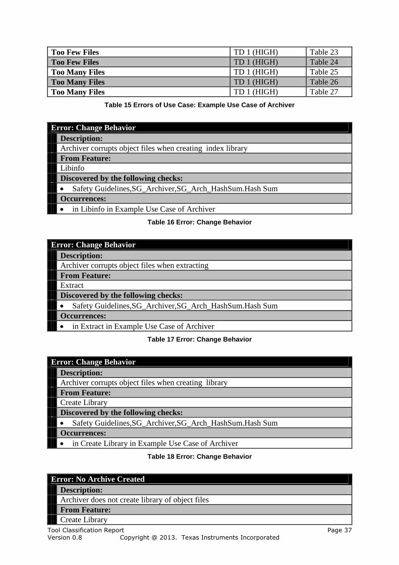
6.2.3 Potential Errors in Archiver
For the tool 12 different potential errors are considered in 12 with occurrences in use cases:
Change Behavior (Table 16)
Change Behavior (Table 17)
Change Behavior (Table 18)
No Archive Created (Table 19)
No Files Extracted (Table 20)
No Index Created (Table 21)
Too Few Files (Table 23)
Too Few Files (Table 24)
Too Few Files (Table 22)
Too Many Files (Table 25)
Too Many Files (Table 27)
Too Many Files (Table 26)
The error flow consists of all relations from errors to checks or restrictions.
There is no relation from errors caused by other tools to checks or restrictions defined
for use cases of this tool.
There are 12 relations from errors caused by this tool to checks or restrictions defined
for use cases of this tool.
There is no relation from errors caused by this tool to checks or restrictions defined for
use cases of other tools.

Tool Classification Report Page 35 Version 0.8 Copyright @ 2013. Texas Instruments Incorporated
6.2.4 Required Safety Guidelines of Archiver
This section describes all 2 applied safety guidelines of Archiver.
The following tables give an overview of the applied safety guidelines of Archiver .
Safety Guidelines,SG_Archiver,SG_Arch_HashSum
Description:
Container for the mitigation
Contains the following checks:
Hash Sum
Table 11 Safety Guidelines,SG_Archiver,SG_Arch_HashSum
Safety Guidelines,SG_Archiver,SG_Arch_RefFileList
Description:
Container for the mitigation
Contains the following checks:
Compare With Reference List
Table 12 Safety Guidelines,SG_Archiver,SG_Arch_RefFileList
6.2.5 Restrictions in Archiver
For the tool Archiver no restrictions are considered.
6.2.6 Checks in Archiver
The following 2 checks are performed in the tool Archiver.
Check: Compare With Reference List
Description:
The output of the archiver are compared with a reference file list that contains the
expected files
Comment:
Any other use of the output files, e.g. in an automated packaging process is equivalent to
this check
From Feature:
Archiver,Archiver,Archiver,Safety Guidelines,SG_Archiver,SG_Arch_RefFileList
Occurrences:
in SG_Arch_RefFileList in Example Use Case of Archiver
Error detection probability:
TD 1 (HIGH)
Detected errors:
Create Library,No Archive Created
Create Library,Too Few Files
Create Library,Too Many Files
Extract,No Files Extracted
Extract,Too Few Files
Extract,Too Many Files
Libinfo,No Index Created
Libinfo,Too Few Files

Tool Classification Report Page 36 Version 0.8 Copyright @ 2013. Texas Instruments Incorporated
Libinfo,Too Many Files
Table 13 Check: Compare With Reference List
Check: Hash Sum
Description:
Using a hash code of the file(s) it can be detected if they deviate from the expectations
Comment:
A binary comparisson with reference values is equivalent to this check
From Feature:
Archiver,Archiver,Archiver,Safety Guidelines,SG_Archiver,SG_Arch_HashSum
Occurrences:
in SG_Arch_HashSum in Example Use Case of Archiver
Error detection probability:
TD 1 (HIGH)
Detected errors:
Create Library,Change Behavior
Extract,Change Behavior
Libinfo,Change Behavior
Table 14 Check: Hash Sum
6.2.7 TCL Determination
This section determines a TCL for each use case by assigning checks or restrictions with
detection/avoidance probability to each potential error. The TCL for the entire tool can be
derived from the TCL for each use case. The tool Archiver has one use case with TCL 1, no
use case with TCL 2 and no use case with TCL 3. Therefore the tool Archiver has TCL 1.
The use cases are described in the following sections:
For "Example Use Case of Archiver" (TCL 1) see Section 6.2.7.1.
6.2.7.1 TCL Determination for Use Case: Example Use Case of Archiver
The use case "Example Use Case of Archiver" has TCL 1. The TCL is determined by the
lowest Tool Detection Level (TD) of all errors of the use case. The use case "Example Use
Case of Archiver" has 3 features that have been modeled and from which the potential errors
are inferred. There are 12 potential errors in "Example Use Case of Archiver": 12 with TD 1,
0 with TD 2 and 0 with TD 3. The 12 potential errors are described in the remainder of this
section.
The following table gives an overview of the errors of "Example Use Case of Archiver".
Error TD Table
Change Behavior TD 1 (HIGH) Table 16
Change Behavior TD 1 (HIGH) Table 17
Change Behavior TD 1 (HIGH) Table 18
No Archive Created TD 1 (HIGH) Table 19
No Files Extracted TD 1 (HIGH) Table 20
No Index Created TD 1 (HIGH) Table 21
Too Few Files TD 1 (HIGH) Table 22
Tool Classification Report Page 37 Version 0.8 Copyright @ 2013. Texas Instruments Incorporated
Too Few Files TD 1 (HIGH) Table 23
Too Few Files TD 1 (HIGH) Table 24
Too Many Files TD 1 (HIGH) Table 25
Too Many Files TD 1 (HIGH) Table 26
Too Many Files TD 1 (HIGH) Table 27
Table 15 Errors of Use Case: Example Use Case of Archiver
Error: Change Behavior
Description:
Archiver corrupts object files when creating index library
From Feature:
Libinfo
Discovered by the following checks:
Safety Guidelines,SG_Archiver,SG_Arch_HashSum.Hash Sum
Occurrences:
in Libinfo in Example Use Case of Archiver
Table 16 Error: Change Behavior
Error: Change Behavior
Description:
Archiver corrupts object files when extracting
From Feature:
Extract
Discovered by the following checks:
Safety Guidelines,SG_Archiver,SG_Arch_HashSum.Hash Sum
Occurrences:
in Extract in Example Use Case of Archiver
Table 17 Error: Change Behavior
Error: Change Behavior
Description:
Archiver corrupts object files when creating library
From Feature:
Create Library
Discovered by the following checks:
Safety Guidelines,SG_Archiver,SG_Arch_HashSum.Hash Sum
Occurrences:
in Create Library in Example Use Case of Archiver
Table 18 Error: Change Behavior
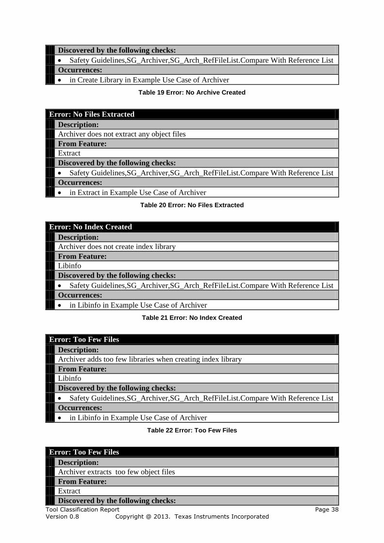
Error: No Archive Created
Description:
Archiver does not create library of object files
From Feature:
Create Library
Tool Classification Report Page 38 Version 0.8 Copyright @ 2013. Texas Instruments Incorporated
Discovered by the following checks:
Safety Guidelines,SG_Archiver,SG_Arch_RefFileList.Compare With Reference List
Occurrences:
in Create Library in Example Use Case of Archiver
Table 19 Error: No Archive Created
Error: No Files Extracted
Description:
Archiver does not extract any object files
From Feature:
Extract
Discovered by the following checks:
Safety Guidelines,SG_Archiver,SG_Arch_RefFileList.Compare With Reference List
Occurrences:
in Extract in Example Use Case of Archiver
Table 20 Error: No Files Extracted
Error: No Index Created
Description:
Archiver does not create index library
From Feature:
Libinfo
Discovered by the following checks:
Safety Guidelines,SG_Archiver,SG_Arch_RefFileList.Compare With Reference List
Occurrences:
in Libinfo in Example Use Case of Archiver
Table 21 Error: No Index Created
Error: Too Few Files
Description:
Archiver adds too few libraries when creating index library
From Feature:
Libinfo
Discovered by the following checks:
Safety Guidelines,SG_Archiver,SG_Arch_RefFileList.Compare With Reference List
Occurrences:
in Libinfo in Example Use Case of Archiver
Table 22 Error: Too Few Files
Error: Too Few Files
Description:
Archiver extracts too few object files
From Feature:
Extract
Discovered by the following checks:
Tool Classification Report Page 39 Version 0.8 Copyright @ 2013. Texas Instruments Incorporated
Safety Guidelines,SG_Archiver,SG_Arch_RefFileList.Compare With Reference List
Occurrences:
in Extract in Example Use Case of Archiver
Table 23 Error: Too Few Files
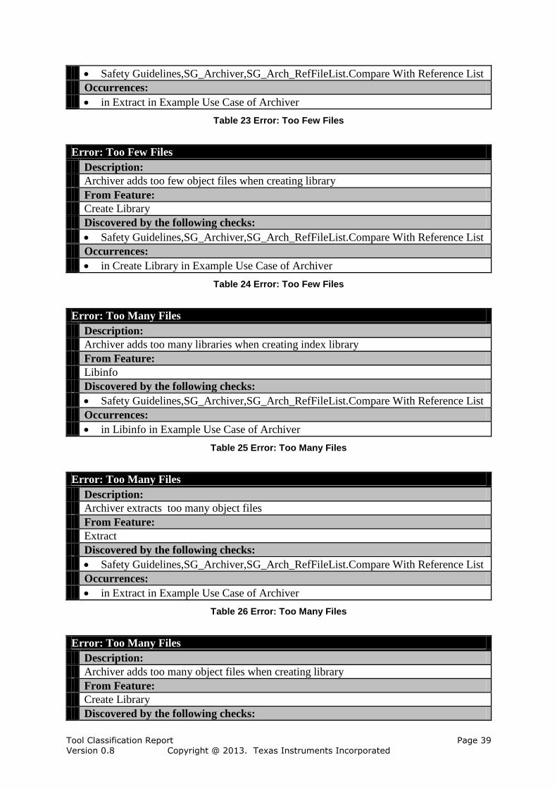
Error: Too Few Files
Description:
Archiver adds too few object files when creating library
From Feature:
Create Library
Discovered by the following checks:
Safety Guidelines,SG_Archiver,SG_Arch_RefFileList.Compare With Reference List
Occurrences:
in Create Library in Example Use Case of Archiver
Table 24 Error: Too Few Files
Error: Too Many Files
Description:
Archiver adds too many libraries when creating index library
From Feature:
Libinfo
Discovered by the following checks:
Safety Guidelines,SG_Archiver,SG_Arch_RefFileList.Compare With Reference List
Occurrences:
in Libinfo in Example Use Case of Archiver
Table 25 Error: Too Many Files
Error: Too Many Files
Description:
Archiver extracts too many object files
From Feature:
Extract
Discovered by the following checks:
Safety Guidelines,SG_Archiver,SG_Arch_RefFileList.Compare With Reference List
Occurrences:
in Extract in Example Use Case of Archiver
Table 26 Error: Too Many Files
Error: Too Many Files
Description:
Archiver adds too many object files when creating library
From Feature:
Create Library
Discovered by the following checks:
Tool Classification Report Page 40 Version 0.8 Copyright @ 2013. Texas Instruments Incorporated
Safety Guidelines,SG_Archiver,SG_Arch_RefFileList.Compare With Reference List
Occurrences:
in Create Library in Example Use Case of Archiver
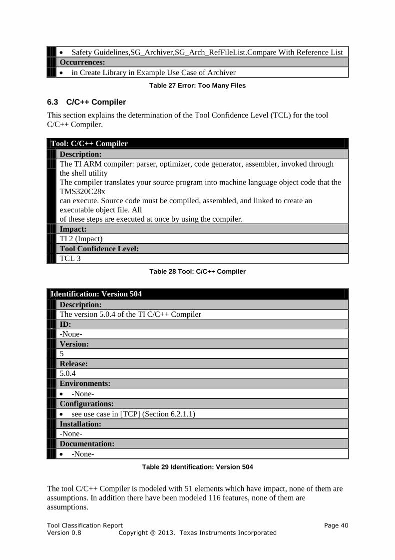
Table 27 Error: Too Many Files
6.3 C/C++ Compiler
This section explains the determination of the Tool Confidence Level (TCL) for the tool
C/C++ Compiler.
Tool: C/C++ Compiler
Description:
The TI ARM compiler: parser, optimizer, code generator, assembler, invoked through
the shell utility
The compiler translates your source program into machine language object code that the
TMS320C28x
can execute. Source code must be compiled, assembled, and linked to create an
executable object file. All
of these steps are executed at once by using the compiler.
Impact:
TI 2 (Impact)
Tool Confidence Level:
TCL 3
Table 28 Tool: C/C++ Compiler
Identification: Version 504
Description:
The version 5.0.4 of the TI C/C++ Compiler
ID:
-None-
Version:
5
Release:
5.0.4
Environments:
-None-
Configurations:
see use case in [TCP] (Section 6.2.1.1)
Installation:
-None-
Documentation:
-None-
Table 29 Identification: Version 504
The tool C/C++ Compiler is modeled with 51 elements which have impact, none of them are
assumptions. In addition there have been modeled 116 features, none of them are
assumptions.

Tool Classification Report Page 41 Version 0.8 Copyright @ 2013. Texas Instruments Incorporated
Elements Amount (Assumptions)
Use Cases 1 (0)
Checks 13 (0)
Restrictions 0 (0)
Potential Errors 37 (0)
Table 30 Amount of Elements in Tool C/C++ Compiler
6.3.1 Use Cases of C/C++ Compiler
This section describes all analyzed use cases of C/C++ Compiler in separate subsections.
The following use cases of the tool C/C++ Compiler are considered:
1. Example Use Case, see Section 6.3.1.1
6.3.1.1 Use Case Example Use Case
This section describes the use case "Example Use Case".
Use Case: Example Use Case
Description:
This is just an example use case that shows how a use case is configured by selecting
your required features.
Comment:
Change use according to your needs.
Table 31 Use Case: Example Use Case
The use case requires 9 features and calls no other use cases.
"Example Use Case" uses following features:
16 Bit Thumb Code Generation
ARM Target Specific Code
Big endian code generation
C language source
EABI specific code generation
Include path update
MISRA C source diagnostics
Output file directory
Predefined symbol (macros) support
"Example Use Case" uses following safety guidelines:
SG_Comp_FixConfig
SG_Compiler
SG_General
SG_Linker
SG_Lnk_CompOutputList
SG_Lnk_ReviewDissaembler
SG_Lnk_ReviewLinkInfo
SG_Lnk_ReviewMapfileSimple

Tool Classification Report Page 42 Version 0.8 Copyright @ 2013. Texas Instruments Incorporated
SG_Misra
SG_Misra_Redundancy
SG_OutFiles
SG_Out_CompareWithList
SG_Out_PchCompare
SG_Parser
SG_Pre_Redundancy
SG_Preprocessor
SG_TBD
SG_TargetTest
SG_Test_Debug
SG_Test_General
SG_Test_Intensive
Safety Guide
"Example Use Case" has the following 4 features that have high error detection probability:
Big endian code generation
Include path update
MISRA C source diagnostics
Predefined symbol (macros) support
6.3.2 Required Features of C/C++ Compiler
This section describes all 9 required features of C/C++ Compiler.
The following tables give an overview of the considered features of C/C++ Compiler.
Feature: 16 Bit Thumb Code Generation
Description:
-mt, --code_state=16
Errors:
Change behavior
Missing code
No output
Table 32 Feature: 16 Bit Thumb Code Generation
Feature: ARM Target Specific Code
Description:
-mv4, -mv5e, -mv6, -mv6M0, -mv7A8, -mv7M3, -mv7M4, -mv7R4
ARM target specific code generation.
Errors:
Change behavior
Missing code
No output
Wrong code
Table 33 Feature: ARM Target Specific Code
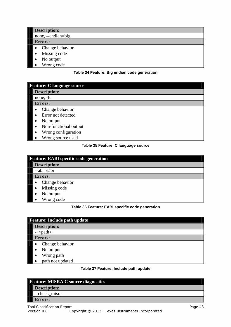
Feature: Big endian code generation
Tool Classification Report Page 43 Version 0.8 Copyright @ 2013. Texas Instruments Incorporated
Description:
none, --endian=big
Errors:
Change behavior
Missing code
No output
Wrong code
Table 34 Feature: Big endian code generation
Feature: C language source
Description:
none, -fc
Errors:
Change behavior
Error not detected
No output
Non-functional output
Wrong configuration
Wrong source used
Table 35 Feature: C language source
Feature: EABI specific code generation
Description:
--abi=eabi
Errors:
Change behavior
Missing code
No output
Wrong code
Table 36 Feature: EABI specific code generation
Feature: Include path update
Description:
-| <path>
Errors:
Change behavior
No output
Wrong path
path not updated
Table 37 Feature: Include path update
Feature: MISRA C source diagnostics
Description:
--check_misra
Errors:

Tool Classification Report Page 44 Version 0.8 Copyright @ 2013. Texas Instruments Incorporated
Change behavior
No diagnostics
No output
Wrong diagnostics
Table 38 Feature: MISRA C source diagnostics
Feature: Output file directory
Description:
-ft, -fr, -fs
Errors:
Change behavior
No output
Output Directory Wrong
Wrong Directory
Table 39 Feature: Output file directory
Feature: Predefined symbol (macros) support
Description:
-D, -U
Errors:
Change behavior
No output
Symbol ignored
Wrong symbol
Table 40 Feature: Predefined symbol (macros) support
6.3.3 Potential Errors in C/C++ Compiler
For the tool 37 different potential errors are considered in 37 with occurrences in use cases:
Change behavior (Table 77)
Change behavior (Table 76)
Change behavior (Table 72)
Change behavior (Table 74)
Change behavior (Table 73)
Change behavior (Table 75)
Change behavior (Table 80)
Change behavior (Table 79)
Change behavior (Table 78)
Error not detected (Table 81)
Missing code (Table 83)
Missing code (Table 84)
Missing code (Table 85)
Missing code (Table 82)
No diagnostics (Table 86)
No output (Table 92)
No output (Table 88)
No output (Table 90)

Tool Classification Report Page 45 Version 0.8 Copyright @ 2013. Texas Instruments Incorporated
No output (Table 89)
No output (Table 93)
No output (Table 87)
No output (Table 91)
No output (Table 94)
No output (Table 95)
Non-functional output (Table 96)
Output Directory Wrong (Table 97)
Symbol ignored (Table 99)
Wrong Directory (Table 105)
Wrong code (Table 100)
Wrong code (Table 102)
Wrong code (Table 101)
Wrong configuration (Table 103)
Wrong diagnostics (Table 104)
Wrong path (Table 106)
Wrong source used (Table 107)
Wrong symbol (Table 108)
path not updated (Table 98)
The error flow consists of all relations from errors to checks or restrictions.
There is no relation from errors caused by other tools to checks or restrictions defined
for use cases of this tool.
There are 52 relations from errors caused by this tool to checks or restrictions defined
for use cases of this tool.
There is no relation from errors caused by this tool to checks or restrictions defined for
use cases of other tools.
6.3.4 Required Safety Guidelines of C/C++ Compiler
This section describes all 17 applied safety guidelines of C/C++ Compiler.
The following tables give an overview of the applied safety guidelines of C/C++ Compiler .
Safety Guide
Description:
This virtual feature contains safety guidelines can be selected within use cases in order to
apply the checks
Table 41 Safety Guide
Safety Guide,SG_Compiler
Description:
Container for guidelines for the compiler
Table 42 Safety Guide,SG_Compiler
Safety Guide,SG_General
Description:
General safety guidelines

Tool Classification Report Page 46 Version 0.8 Copyright @ 2013. Texas Instruments Incorporated
Table 43 Safety Guide,SG_General
Safety Guide,SG_Misra
Description:
Guidelines for MISRA checks
Table 44 Safety Guide,SG_Misra
Safety Guide,SG_Misra,SG_Misra_Redundancy
Description:
Guideline to use a third party checker
Contains the following checks:
Third Party Checker
Table 45 Safety Guide,SG_Misra,SG_Misra_Redundancy
Safety Guide,SG_OutFiles
Description:
Guidelines for the output file checks
Table 46 Safety Guide,SG_OutFiles
Safety Guide,SG_OutFiles,SG_Out_CompareWithList
Description:
guideline to apply the comaprisson with output reference list
Contains the following checks:
Reference List
Table 47 Safety Guide,SG_OutFiles,SG_Out_CompareWithList
Safety Guide,SG_OutFiles,SG_Out_PchCompare
Description:
Guideline to apply this comparisson
Contains the following checks:
Precompiled Reference List
Table 48 Safety Guide,SG_OutFiles,SG_Out_PchCompare
Safety Guide,SG_Parser
Description:
Guidelines for the parser
Table 49 Safety Guide,SG_Parser
Safety Guide,SG_Parser,SG_Comp_FixConfig
Description:
Guideline to fix the configuration of the parser
Contains the following checks:
Use Config File

Tool Classification Report Page 47 Version 0.8 Copyright @ 2013. Texas Instruments Incorporated
Table 50 Safety Guide,SG_Parser,SG_Comp_FixConfig
Safety Guide,SG_Preprocessor
Description:
Safety guidelines for the preprocessor feature
Table 51 Safety Guide,SG_Preprocessor
Safety Guide,SG_Preprocessor,SG_Pre_Redundancy
Description:
Guideline to apply the comparisson with a redundant preprocessor
Contains the following checks:
Third Party Preprocessor
Table 52 Safety Guide,SG_Preprocessor,SG_Pre_Redundancy
Safety Guide,SG_TargetTest
Description:
If the compiled code is tested on the target and if it is tested in all possible situations than
all relevant compiler errors can be found
Inputs:
Executable file
Table 53 Safety Guide,SG_TargetTest
Safety Guide,SG_TargetTest,SG_Test_Debug
Description:
Guideline to apply a testrun before and after debug information generation
Contains the following checks:
Debugger Run
Table 54 Safety Guide,SG_TargetTest,SG_Test_Debug
Safety Guide,SG_TargetTest,SG_Test_General
Description:
Guideline to do a general test
Contains the following checks:
General Testrun
Table 55 Safety Guide,SG_TargetTest,SG_Test_General
Safety Guide,SG_TargetTest,SG_Test_Intensive
Description:
Container for the safety guideline
Contains the following checks:
Intensive Target Testing
Table 56 Safety Guide,SG_TargetTest,SG_Test_Intensive

Tool Classification Report Page 48 Version 0.8 Copyright @ 2013. Texas Instruments Incorporated
Safety Guide,SG_TBD
Description:
Container for safety guidelines that hvae to be defined from the user in his procss
Contains the following checks:
To Be Defined By User
Table 57 Safety Guide,SG_TBD
6.3.5 Restrictions in C/C++ Compiler
For the tool C/C++ Compiler no restrictions are considered.
6.3.6 Checks in C/C++ Compiler
The following 13 checks are performed in the tool C/C++ Compiler.
Check: Compare Linker Output Files with Reference File List
Description:
The generated amount of files will be compared with a reference file list, which contains
all file names that have to be created
From Feature:
Linker,Linker,Linker,Safety Guide,SG_Linker,SG_Lnk_CompOutputList
Occurrences:
in SG_Lnk_CompOutputList in Example Use Case
Error detection probability:
TD 1 (HIGH)
Detected errors:
Add to library search path,No output
BE-8 and BE-32 object file support,No Output
Control linker diagnostics,No Output
Control symbol linkage,No Output
Control variable initialization,No output
Copy Tables,No Output
Create executable object file,No executable
Disable COFF conditional linking,No Output
Generate map file,No map file
Generate map file,No output
Generate xml link info file,No info file
Generate xml link info file,No output
LCF MEMORY directives,No Output
LCF SECTIONS directives,Change Behavior
LCF SECTIONS directives,No Output
LCF UNION and GROUP statements,No Output
LCF assignment of symbols,No Output
LCF creating and filling holes,No Output
Link time optimizations,No Output
Linker preprocessing,No Output
Partial Linking,No object file
Preferred function ordering,No Output
Set executable entry point,No Output

Tool Classification Report Page 49 Version 0.8 Copyright @ 2013. Texas Instruments Incorporated
Set heap size,No output
Set output file name,No output file name
Set output file name,Wrong output file name
Set stack size,No output
Support library input files,No output
Table 58 Check: Compare Linker Output Files with Reference File List
Check: Debugger Run
Description:
General testrun in the debugger
From Feature:
C/C++ Compiler,C/C++ Compiler,C/C++ Compiler,Safety
Guide,SG_TargetTest,SG_Test_Debug
Occurrences:
in SG_Test_Debug in Example Use Case
Error detection probability:
TD 1 (HIGH)
Table 59 Check: Debugger Run
Check: General Testrun
Description:
A simple test run can exclude many errors in the tool chain which result in a non
runnable image file. If other test are executed the general test run can be omitted
From Feature:
C/C++ Compiler,C/C++ Compiler,C/C++ Compiler,Safety
Guide,SG_TargetTest,SG_Test_General
Occurrences:
in SG_Test_General in Example Use Case
Error detection probability:
TD 1 (HIGH)
Detected errors:
Big endian code generation,Missing code
Big endian code generation,Wrong code
C language source,Non-functional output
Include path update,Wrong path
Include path update,path not updated
Table 60 Check: General Testrun
Check: Intensive Target Testing
Description:
-None-
From Feature:
C/C++ Compiler,C/C++ Compiler,C/C++ Compiler,Safety
Guide,SG_TargetTest,SG_Test_Intensive
Occurrences:
in SG_Test_Intensive in Example Use Case

Tool Classification Report Page 50 Version 0.8 Copyright @ 2013. Texas Instruments Incorporated
Error detection probability:
TD 1 (HIGH)
Detected errors:
16 Bit Thumb Code Generation,Change behavior
ARM Target Specific Code,Change behavior
Big endian code generation,Change behavior
C language source,Change behavior
C language source,Error not detected
EABI specific code generation,Change behavior
Include path update,Change behavior
MISRA C source diagnostics,Change behavior
Output file directory,Change behavior
Predefined symbol (macros) support,Change behavior
Table 61 Check: Intensive Target Testing
Check: Precompiled Reference List
Description:
Compare output with a list of reference files that should exists
From Feature:
C/C++ Compiler,C/C++ Compiler,C/C++ Compiler,Safety
Guide,SG_OutFiles,SG_Out_PchCompare
Occurrences:
in SG_Out_PchCompare in Example Use Case
Error detection probability:
TD 1 (HIGH)
Table 62 Check: Precompiled Reference List
Check: Reference List
Description:
Compare output with reference file list
From Feature:
C/C++ Compiler,C/C++ Compiler,C/C++ Compiler,Safety
Guide,SG_OutFiles,SG_Out_CompareWithList
Occurrences:
in SG_Out_CompareWithList in Example Use Case
Error detection probability:
TD 1 (HIGH)
Detected errors:
16 Bit Thumb Code Generation,No output
ARM Target Specific Code,No output
Big endian code generation,No output
C language source,No output
EABI specific code generation,No output
Include path update,No output
MISRA C source diagnostics,No output
Output file directory,No output
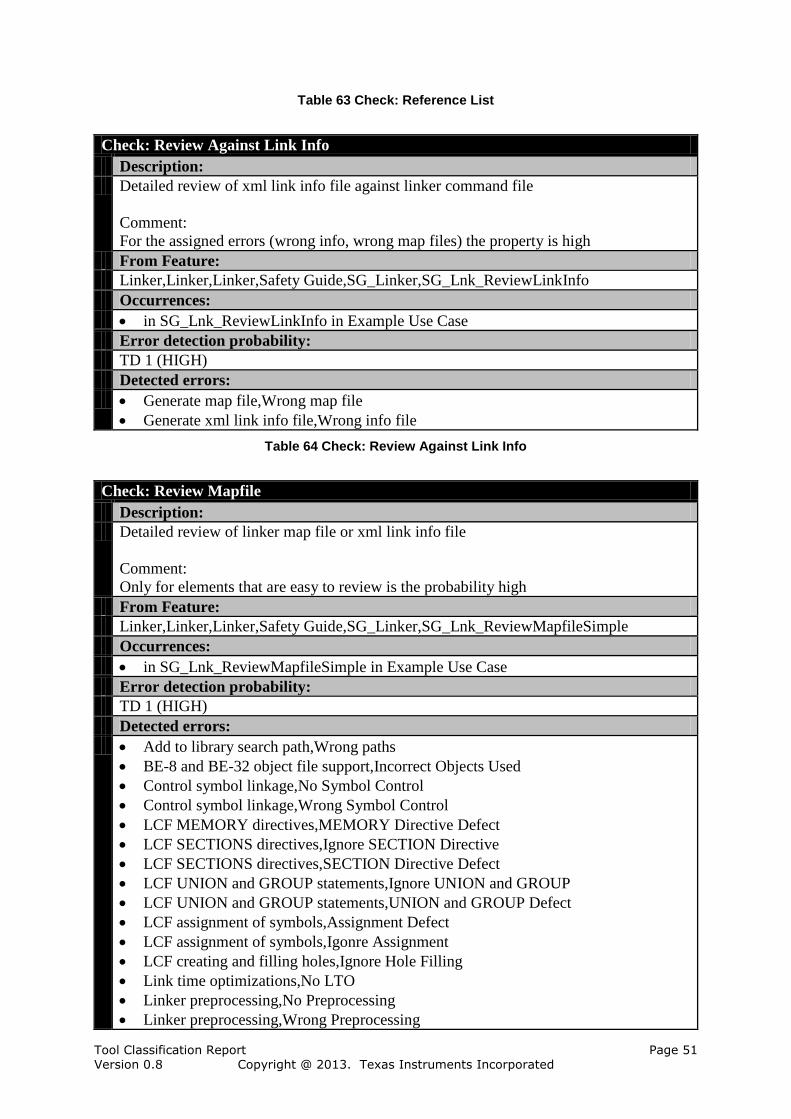
Tool Classification Report Page 51 Version 0.8 Copyright @ 2013. Texas Instruments Incorporated
Table 63 Check: Reference List
Check: Review Against Link Info
Description:
Detailed review of xml link info file against linker command file
Comment:
For the assigned errors (wrong info, wrong map files) the property is high
From Feature:
Linker,Linker,Linker,Safety Guide,SG_Linker,SG_Lnk_ReviewLinkInfo
Occurrences:
in SG_Lnk_ReviewLinkInfo in Example Use Case
Error detection probability:
TD 1 (HIGH)
Detected errors:
Generate map file,Wrong map file
Generate xml link info file,Wrong info file
Table 64 Check: Review Against Link Info
Check: Review Mapfile
Description:
Detailed review of linker map file or xml link info file
Comment:
Only for elements that are easy to review is the probability high
From Feature:
Linker,Linker,Linker,Safety Guide,SG_Linker,SG_Lnk_ReviewMapfileSimple
Occurrences:
in SG_Lnk_ReviewMapfileSimple in Example Use Case
Error detection probability:
TD 1 (HIGH)
Detected errors:
Add to library search path,Wrong paths
BE-8 and BE-32 object file support,Incorrect Objects Used
Control symbol linkage,No Symbol Control
Control symbol linkage,Wrong Symbol Control
LCF MEMORY directives,MEMORY Directive Defect
LCF SECTIONS directives,Ignore SECTION Directive
LCF SECTIONS directives,SECTION Directive Defect
LCF UNION and GROUP statements,Ignore UNION and GROUP
LCF UNION and GROUP statements,UNION and GROUP Defect
LCF assignment of symbols,Assignment Defect
LCF assignment of symbols,Igonre Assignment
LCF creating and filling holes,Ignore Hole Filling
Link time optimizations,No LTO
Linker preprocessing,No Preprocessing
Linker preprocessing,Wrong Preprocessing
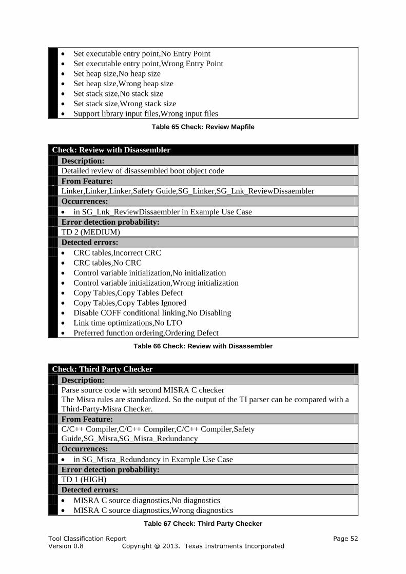
Tool Classification Report Page 52 Version 0.8 Copyright @ 2013. Texas Instruments Incorporated
Set executable entry point,No Entry Point
Set executable entry point,Wrong Entry Point
Set heap size,No heap size
Set heap size,Wrong heap size
Set stack size,No stack size
Set stack size,Wrong stack size
Support library input files,Wrong input files
Table 65 Check: Review Mapfile
Check: Review with Disassembler
Description:
Detailed review of disassembled boot object code
From Feature:
Linker,Linker,Linker,Safety Guide,SG_Linker,SG_Lnk_ReviewDissaembler
Occurrences:
in SG_Lnk_ReviewDissaembler in Example Use Case
Error detection probability:
TD 2 (MEDIUM)
Detected errors:
CRC tables,Incorrect CRC
CRC tables,No CRC
Control variable initialization,No initialization
Control variable initialization,Wrong initialization
Copy Tables,Copy Tables Defect
Copy Tables,Copy Tables Ignored
Disable COFF conditional linking,No Disabling
Link time optimizations,No LTO
Preferred function ordering,Ordering Defect
Table 66 Check: Review with Disassembler
Check: Third Party Checker
Description:
Parse source code with second MISRA C checker
The Misra rules are standardized. So the output of the TI parser can be compared with a
Third-Party-Misra Checker.
From Feature:
C/C++ Compiler,C/C++ Compiler,C/C++ Compiler,Safety
Guide,SG_Misra,SG_Misra_Redundancy
Occurrences:
in SG_Misra_Redundancy in Example Use Case
Error detection probability:
TD 1 (HIGH)
Detected errors:
MISRA C source diagnostics,No diagnostics
MISRA C source diagnostics,Wrong diagnostics
Table 67 Check: Third Party Checker
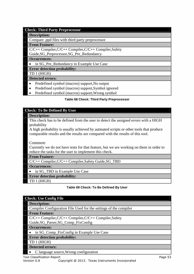
Tool Classification Report Page 53 Version 0.8 Copyright @ 2013. Texas Instruments Incorporated
Check: Third Party Preprocessor
Description:
Compare .ppd files with third party preprocessor
From Feature:
C/C++ Compiler,C/C++ Compiler,C/C++ Compiler,Safety
Guide,SG_Preprocessor,SG_Pre_Redundancy
Occurrences:
in SG_Pre_Redundancy in Example Use Case
Error detection probability:
TD 1 (HIGH)
Detected errors:
Predefined symbol (macros) support,No output
Predefined symbol (macros) support,Symbol ignored
Predefined symbol (macros) support,Wrong symbol
Table 68 Check: Third Party Preprocessor
Check: To Be Defined By User
Description:
This check has to be defined from the user to detect the assigned errors with a HIGH
probability
A high probability is usually achieved by autmated scripts or other tools that produce
comparable results and the results are compared with the results of this tool.
Comment:
Currently we do not have tests for that feature, but we are working on them in order to
reduce the tasks for the user to implement this check.
From Feature:
C/C++ Compiler,C/C++ Compiler,Safety Guide,SG_TBD
Occurrences:
in SG_TBD in Example Use Case
Error detection probability:
TD 1 (HIGH)
Table 69 Check: To Be Defined By User
Check: Use Config File
Description:
Compiler Configuration File Used for the settings of the compiler
From Feature:
C/C++ Compiler,C/C++ Compiler,C/C++ Compiler,Safety
Guide,SG_Parser,SG_Comp_FixConfig
Occurrences:
in SG_Comp_FixConfig in Example Use Case
Error detection probability:
TD 1 (HIGH)
Detected errors:
C language source,Wrong configuration

Tool Classification Report Page 54 Version 0.8 Copyright @ 2013. Texas Instruments Incorporated
Table 70 Check: Use Config File
6.3.7 TCL Determination
This section determines a TCL for each use case by assigning checks or restrictions with
detection/avoidance probability to each potential error. The TCL for the entire tool can be
derived from the TCL for each use case. The tool C/C++ Compiler has no use case with TCL
1, no use case with TCL 2 and one use case with TCL 3. Therefore the tool C/C++ Compiler
has TCL 3.
The use cases are described in the following sections:
For "Example Use Case" (TCL 3) see Section 6.3.7.1.
6.3.7.1 TCL Determination for Use Case: Example Use Case
The use case "Example Use Case" has TCL 3. The TCL is determined by the lowest Tool
Detection Level (TD) of all errors of the use case. The use case "Example Use Case" has 9
features that have been modeled and from which the potential errors are inferred. There are 37
potential errors in "Example Use Case": 29 with TD 1, 0 with TD 2 and 8 with TD 3. The 37
potential errors are described in the remainder of this section.
The following table gives an overview of the errors of "Example Use Case".
Error TD Table
Change behavior TD 1 (HIGH) Table 72
Change behavior TD 1 (HIGH) Table 73
Change behavior TD 1 (HIGH) Table 74
Change behavior TD 1 (HIGH) Table 75
Change behavior TD 1 (HIGH) Table 76
Change behavior TD 1 (HIGH) Table 77
Change behavior TD 1 (HIGH) Table 78
Change behavior TD 1 (HIGH) Table 79
Change behavior TD 1 (HIGH) Table 80
Error not detected TD 1 (HIGH) Table 81
Missing code TD 3 (LOW) Table 82
Missing code TD 1 (HIGH) Table 83
Missing code TD 3 (LOW) Table 84
Missing code TD 3 (LOW) Table 85
No diagnostics TD 1 (HIGH) Table 86
No output TD 1 (HIGH) Table 87
No output TD 1 (HIGH) Table 88
No output TD 1 (HIGH) Table 89
No output TD 1 (HIGH) Table 90
No output TD 1 (HIGH) Table 91
No output TD 1 (HIGH) Table 92
No output TD 1 (HIGH) Table 93
No output TD 1 (HIGH) Table 94
No output TD 1 (HIGH) Table 95
Non-functional output TD 1 (HIGH) Table 96
Output Directory Wrong TD 3 (LOW) Table 97
path not updated TD 1 (HIGH) Table 98

Tool Classification Report Page 55 Version 0.8 Copyright @ 2013. Texas Instruments Incorporated
Symbol ignored TD 1 (HIGH) Table 99
Wrong code TD 3 (LOW) Table 100
Wrong code TD 1 (HIGH) Table 101
Wrong code TD 3 (LOW) Table 102
Wrong configuration TD 1 (HIGH) Table 103
Wrong diagnostics TD 1 (HIGH) Table 104
Wrong Directory TD 3 (LOW) Table 105
Wrong path TD 1 (HIGH) Table 106
Wrong source used TD 3 (LOW) Table 107
Wrong symbol TD 1 (HIGH) Table 108
Table 71 Errors of Use Case: Example Use Case
Error: Change behavior
Description:
Compiler changes the behavior of the C source
From Feature:
C language source
Discovered by the following checks:
Safety
Guide,SG_Compiler,SG_Comp_ComparingRun,SG_Comp_ThirdParty.Compiling
With Second Compiler
Safety Guide,SG_TargetTest,SG_Test_Intensive.Intensive Target Testing
Occurrences:
in C language source in Example Use Case
Table 72 Error: Change behavior
Error: Change behavior
Description:
Change the behavior of the source when compiling with MISRA C diagnostics
From Feature:
MISRA C source diagnostics
Discovered by the following checks:
Safety
Guide,SG_Compiler,SG_Comp_ComparingRun,SG_Comp_ThirdParty.Compiling
With Second Compiler
Safety Guide,SG_TargetTest,SG_Test_Intensive.Intensive Target Testing
Occurrences:
in MISRA C source diagnostics in Example Use Case
Table 73 Error: Change behavior
Error: Change behavior
Description:
Change the behavior of the source when compiling for ARM target specific code
From Feature:
ARM Target Specific Code
Discovered by the following checks:

Tool Classification Report Page 56 Version 0.8 Copyright @ 2013. Texas Instruments Incorporated
Safety
Guide,SG_Compiler,SG_Comp_ComparingRun,SG_Comp_ThirdParty.Compiling
With Second Compiler
Safety Guide,SG_TargetTest,SG_Test_Intensive.Intensive Target Testing
Occurrences:
in ARM Target Specific Code in Example Use Case
Table 74 Error: Change behavior
Error: Change behavior
Description:
Change the behavior of the source when compiling with include path
From Feature:
Include path update
Discovered by the following checks:
Safety
Guide,SG_Compiler,SG_Comp_ComparingRun,SG_Comp_ThirdParty.Compiling
With Second Compiler
Safety Guide,SG_TargetTest,SG_Test_Intensive.Intensive Target Testing
Occurrences:
in Include path update in Example Use Case
Table 75 Error: Change behavior
Error: Change behavior
Description:
Change the behavior of the source when compiling for big endian
From Feature:
Big endian code generation
Discovered by the following checks:
Safety
Guide,SG_Compiler,SG_Comp_ComparingRun,SG_Comp_ThirdParty.Compiling
With Second Compiler
Safety Guide,SG_TargetTest,SG_Test_Intensive.Intensive Target Testing
Occurrences:
in Big endian code generation in Example Use Case
Table 76 Error: Change behavior
Error: Change behavior
Description:
Change the behavior of the source when compiling with output directories
From Feature:
Output file directory
Discovered by the following checks:
Safety Guide,SG_Compiler,SG_Comp_ComparingRun,SG_Comp_Comp
OutputDir.Compare Output Directory Effect
Safety
Guide,SG_Compiler,SG_Comp_ComparingRun,SG_Comp_ThirdParty.Compiling
Tool Classification Report Page 57 Version 0.8 Copyright @ 2013. Texas Instruments Incorporated
With Second Compiler
Safety Guide,SG_TargetTest,SG_Test_Intensive.Intensive Target Testing
Occurrences:
in Output file directory in Example Use Case
Table 77 Error: Change behavior
Error: Change behavior
Description:
Change the behavior of the source when compiling for EABI
From Feature:
EABI specific code generation
Discovered by the following checks:
Safety
Guide,SG_Compiler,SG_Comp_ComparingRun,SG_Comp_ThirdParty.Compiling
With Second Compiler
Safety Guide,SG_TargetTest,SG_Test_Intensive.Intensive Target Testing
Occurrences:
in EABI specific code generation in Example Use Case
Table 78 Error: Change behavior
Error: Change behavior
Description:
Change the behavior of the source when compiling with predefined symbols
From Feature:
Predefined symbol (macros) support
Discovered by the following checks:
Safety
Guide,SG_Compiler,SG_Comp_ComparingRun,SG_Comp_ThirdParty.Compiling
With Second Compiler
Safety Guide,SG_TargetTest,SG_Test_Intensive.Intensive Target Testing
Occurrences:
in Predefined symbol (macros) support in Example Use Case
Table 79 Error: Change behavior
Error: Change behavior
Description:
Change the behavior of the source when compiling for 16-bit thumb code
From Feature:
16 Bit Thumb Code Generation
Discovered by the following checks:
Safety
Guide,SG_Compiler,SG_Comp_ComparingRun,SG_Comp_ThirdParty.Compiling
With Second Compiler
Safety Guide,SG_TargetTest,SG_Test_Intensive.Intensive Target Testing
Occurrences:
in 16 Bit Thumb Code Generation in Example Use Case
Tool Classification Report Page 58 Version 0.8 Copyright @ 2013. Texas Instruments Incorporated
Table 80 Error: Change behavior
Error: Error not detected
Description:
Error in C source when compiling not detected
From Feature:
C language source
Discovered by the following checks:
Safety
Guide,SG_Compiler,SG_Comp_ComparingRun,SG_Comp_ThirdParty.Compiling
With Second Compiler
Safety Guide,SG_TargetTest,SG_Test_Intensive.Intensive Target Testing
Occurrences:
in C language source in Example Use Case
Table 81 Error: Error not detected
Error: Missing code
Description:
Compiler does not generate any ARM target specific code
From Feature:
ARM Target Specific Code
Discovered by the following checks:
Safety Guide,SG_Reviews,SG_Rev_Ass.Review of Generated Assembler Code
Occurrences:
in ARM Target Specific Code in Example Use Case
Table 82 Error: Missing code
Error: Missing code
Description:
Compiler does not generate any big endian code
From Feature:
Big endian code generation
Discovered by the following checks:
Safety Guide,SG_TargetTest,SG_Test_General.General Testrun
Occurrences:
in Big endian code generation in Example Use Case
Table 83 Error: Missing code
Error: Missing code
Description:
Compiler does not generate any EABI code
From Feature:
EABI specific code generation
Discovered by the following checks:
Safety Guide,SG_Reviews,SG_Rev_Ass.Review of Generated Assembler Code

Tool Classification Report Page 59 Version 0.8 Copyright @ 2013. Texas Instruments Incorporated
Occurrences:
in EABI specific code generation in Example Use Case
Table 84 Error: Missing code
Error: Missing code
Description:
Compiler does not generate 16-bit thumb code
From Feature:
16 Bit Thumb Code Generation
Discovered by the following checks:
Safety Guide,SG_Reviews,SG_Rev_Gen.Review generated assembly or object code
Occurrences:
in 16 Bit Thumb Code Generation in Example Use Case
Table 85 Error: Missing code
Error: No diagnostics
Description:
Compiler does not generate any MISRA C diagnostics
From Feature:
MISRA C source diagnostics
Discovered by the following checks:
Safety Guide,SG_Misra,SG_Misra_Redundancy.Third Party Checker
Safety Guide,SG_Reviews,SG_Rev_Source.Source Code Review
Occurrences:
in MISRA C source diagnostics in Example Use Case
Table 86 Error: No diagnostics
Error: No output
Description:
No output generated from Compiler for C source
From Feature:
C language source
Discovered by the following checks:
Safety Guide,SG_OutFiles,SG_Out_CompareWithList.Reference List
Occurrences:
in C language source in Example Use Case
Table 87 Error: No output
Error: No output
Description:
No output generated from compiler when using MISRA C diagnostics
From Feature:
MISRA C source diagnostics
Discovered by the following checks:
Safety Guide,SG_OutFiles,SG_Out_CompareWithList.Reference List

Tool Classification Report Page 60 Version 0.8 Copyright @ 2013. Texas Instruments Incorporated
Occurrences:
in MISRA C source diagnostics in Example Use Case
Table 88 Error: No output
Error: No output
Description:
No output generated from compiler when compiling for ARM target specific code
From Feature:
ARM Target Specific Code
Discovered by the following checks:
Safety Guide,SG_OutFiles,SG_Out_CompareWithList.Reference List
Occurrences:
in ARM Target Specific Code in Example Use Case
Table 89 Error: No output
Error: No output
Description:
No output generated from compiler when updating include path
From Feature:
Include path update
Discovered by the following checks:
Safety Guide,SG_OutFiles,SG_Out_CompareWithList.Reference List
Occurrences:
in Include path update in Example Use Case
Table 90 Error: No output
Error: No output
Description:
No output generated from compiler when compiling for big endian
From Feature:
Big endian code generation
Discovered by the following checks:
Safety Guide,SG_OutFiles,SG_Out_CompareWithList.Reference List
Occurrences:
in Big endian code generation in Example Use Case
Table 91 Error: No output
Error: No output
Description:
No output generated from compiler when specifying output directories
From Feature:
Output file directory
Discovered by the following checks:
Safety Guide,SG_OutFiles,SG_Out_CompareWithList.Reference List
Occurrences:

Tool Classification Report Page 61 Version 0.8 Copyright @ 2013. Texas Instruments Incorporated
in Output file directory in Example Use Case
Table 92 Error: No output
Error: No output
Description:
No output generated from compiler when compiling for EABI
From Feature:
EABI specific code generation
Discovered by the following checks:
Safety Guide,SG_OutFiles,SG_Out_CompareWithList.Reference List
Occurrences:
in EABI specific code generation in Example Use Case
Table 93 Error: No output
Error: No output
Description:
No output generated from compiler when using predefined symbols
From Feature:
Predefined symbol (macros) support
Discovered by the following checks:
Safety Guide,SG_Preprocessor,SG_Pre_Redundancy.Third Party Preprocessor
Occurrences:
in Predefined symbol (macros) support in Example Use Case
Table 94 Error: No output
Error: No output
Description:
No output generated from compiler for 16-bit thumb code
From Feature:
16 Bit Thumb Code Generation
Discovered by the following checks:
Safety Guide,SG_OutFiles,SG_Out_CompareWithList.Reference List
Occurrences:
in 16 Bit Thumb Code Generation in Example Use Case
Table 95 Error: No output
Error: Non-functional output
Description:
Non-functional output from compiling C source
From Feature:
C language source
Discovered by the following checks:
Safety Guide,SG_TargetTest,SG_Test_General.General Testrun
Occurrences:
Tool Classification Report Page 62 Version 0.8 Copyright @ 2013. Texas Instruments Incorporated
in C language source in Example Use Case
Table 96 Error: Non-functional output
Error: Output Directory Wrong
Description:
Compiler does not output to specified directory
From Feature:
Output file directory
Discovered by the following checks:
Safety Guide,SG_Reviews,SG_Rev_Build.Review Build Directory
Occurrences:
in Output file directory in Example Use Case
Table 97 Error: Output Directory Wrong
Error: path not updated
Description:
Compiler does not update include path
From Feature:
Include path update
Discovered by the following checks:
Safety Guide,SG_TargetTest,SG_Test_General.General Testrun
Occurrences:
in Include path update in Example Use Case
Table 98 Error: path not updated
Error: Symbol ignored
Description:
Compiler ignores predefined symbols
From Feature:
Predefined symbol (macros) support
Discovered by the following checks:
Safety Guide,SG_Preprocessor,SG_Pre_Redundancy.Third Party Preprocessor
Safety Guide,SG_Reviews,SG_Rev_PPD.PPD File Review
Occurrences:
in Predefined symbol (macros) support in Example Use Case
Table 99 Error: Symbol ignored
Error: Wrong code
Description:
Compiler generates wrong ARM target specific code
From Feature:
ARM Target Specific Code
Discovered by the following checks:
Safety Guide,SG_Reviews,SG_Rev_Ass.Review of Generated Assembler Code
Occurrences:

Tool Classification Report Page 63 Version 0.8 Copyright @ 2013. Texas Instruments Incorporated
in ARM Target Specific Code in Example Use Case
Table 100 Error: Wrong code
Error: Wrong code
Description:
Compiler generates wrong big endian code
From Feature:
Big endian code generation
Discovered by the following checks:
Safety Guide,SG_TargetTest,SG_Test_General.General Testrun
Occurrences:
in Big endian code generation in Example Use Case
Table 101 Error: Wrong code
Error: Wrong code
Description:
Compiler generates wrong EABI code
From Feature:
EABI specific code generation
Discovered by the following checks:
Safety Guide,SG_Reviews,SG_Rev_Ass.Review of Generated Assembler Code
Occurrences:
in EABI specific code generation in Example Use Case
Table 102 Error: Wrong code
Error: Wrong configuration
Description:
Compiler wrongly configured for C source
From Feature:
C language source
Discovered by the following checks:
Safety Guide,SG_Parser,SG_Comp_FixConfig.Use Config File
Occurrences:
in C language source in Example Use Case
Table 103 Error: Wrong configuration
Error: Wrong diagnostics
Description:
Compiler generates wrong MISRA C diagnostics
From Feature:
MISRA C source diagnostics
Discovered by the following checks:
Safety Guide,SG_Misra,SG_Misra_Redundancy.Third Party Checker
Safety Guide,SG_Reviews,SG_Rev_Diagnostic.Review of Disgnostics Sources
Occurrences:
Tool Classification Report Page 64 Version 0.8 Copyright @ 2013. Texas Instruments Incorporated
in MISRA C source diagnostics in Example Use Case
Table 104 Error: Wrong diagnostics
Error: Wrong Directory
Description:
Compiler outputs to wrong directory
From Feature:
Output file directory
Discovered by the following checks:
Safety Guide,SG_Reviews,SG_Rev_Build.Review Build Directory
Occurrences:
in Output file directory in Example Use Case
Table 105 Error: Wrong Directory
Error: Wrong path
Description:
Compiler generates wrong include paths
From Feature:
Include path update
Discovered by the following checks:
Safety Guide,SG_TargetTest,SG_Test_General.General Testrun
Occurrences:
in Include path update in Example Use Case
Table 106 Error: Wrong path
Error: Wrong source used
Description:
Wrong C source used when compiling
From Feature:
C language source
Discovered by the following checks:
Safety Guide,SG_General,SG_Gen_VersionControl.Verify through version control
system
Occurrences:
in C language source in Example Use Case
Table 107 Error: Wrong source used
Error: Wrong symbol
Description:
Compiler generates wrong predefined symbol output
From Feature:
Predefined symbol (macros) support
Discovered by the following checks:
Safety Guide,SG_Preprocessor,SG_Pre_Redundancy.Third Party Preprocessor
Safety Guide,SG_Reviews,SG_Rev_PPD.PPD File Review

Tool Classification Report Page 65 Version 0.8 Copyright @ 2013. Texas Instruments Incorporated
Occurrences:
in Predefined symbol (macros) support in Example Use Case
Table 108 Error: Wrong symbol
6.4 Compiler Utilities
This section explains the determination of the Tool Confidence Level (TCL) for the tool
Compiler Utilities.
Tool: Compiler Utilities
Description:
Other utilities on the compiler, modelled as features of this tool box.
Impact:
TI 2 (Impact)
Tool Confidence Level:
TCL 2
Table 109 Tool: Compiler Utilities
The tool Compiler Utilities is modeled with 16 elements which have impact, none of them are
assumptions. In addition there have been modeled 12 features, none of them are assumptions.
Elements Amount (Assumptions)
Use Cases 1 (0)
Checks 3 (0)
Restrictions 0 (0)
Potential Errors 12 (0)
Table 110 Amount of Elements in Tool Compiler Utilities
6.4.1 Use Cases of Compiler Utilities
This section describes all analyzed use cases of Compiler Utilities in separate subsections.
The following use cases of the tool Compiler Utilities are considered:
1. Example Use Case of Utilities, see Section 6.4.1.1
6.4.1.1 Use Case Example Use Case of Utilities
This section describes the use case "Example Use Case of Utilities".
Use Case: Example Use Case of Utilities
Description:
This is just an example use case that shows how a use case is configured by selecting
your required features.
Comment:
Change use according to your needs.
Table 111 Use Case: Example Use Case of Utilities
The use case requires 6 features and calls no other use cases.
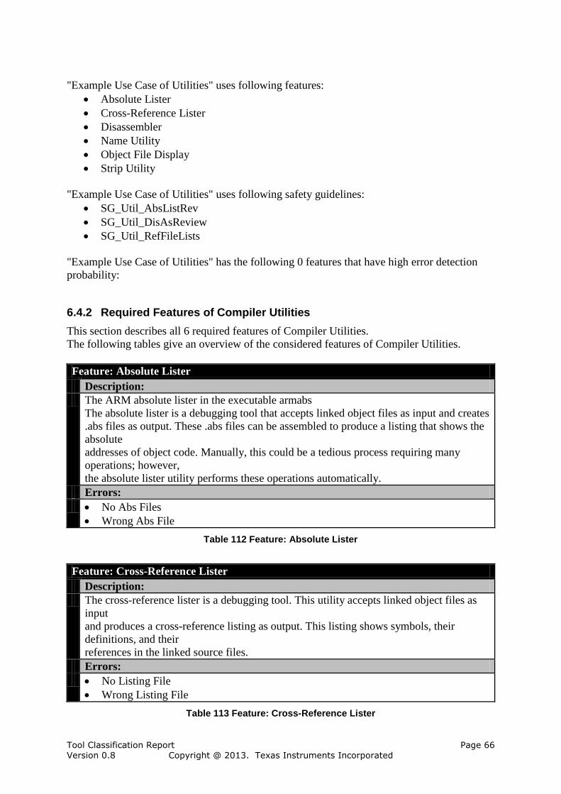
Tool Classification Report Page 66 Version 0.8 Copyright @ 2013. Texas Instruments Incorporated
"Example Use Case of Utilities" uses following features:
Absolute Lister
Cross-Reference Lister
Disassembler
Name Utility
Object File Display
Strip Utility
"Example Use Case of Utilities" uses following safety guidelines:
SG_Util_AbsListRev
SG_Util_DisAsReview
SG_Util_RefFileLists
"Example Use Case of Utilities" has the following 0 features that have high error detection
probability:
6.4.2 Required Features of Compiler Utilities
This section describes all 6 required features of Compiler Utilities.
The following tables give an overview of the considered features of Compiler Utilities.
Feature: Absolute Lister
Description:
The ARM absolute lister in the executable armabs
The absolute lister is a debugging tool that accepts linked object files as input and creates
.abs files as output. These .abs files can be assembled to produce a listing that shows the
absolute
addresses of object code. Manually, this could be a tedious process requiring many
operations; however,
the absolute lister utility performs these operations automatically.
Errors:
No Abs Files
Wrong Abs File
Table 112 Feature: Absolute Lister
Feature: Cross-Reference Lister
Description:
The cross-reference lister is a debugging tool. This utility accepts linked object files as
input
and produces a cross-reference listing as output. This listing shows symbols, their
definitions, and their
references in the linked source files.
Errors:
No Listing File
Wrong Listing File
Table 113 Feature: Cross-Reference Lister

Tool Classification Report Page 67 Version 0.8 Copyright @ 2013. Texas Instruments Incorporated
Feature: Disassembler
Description:
the ARM disassemblerin the executable armdis
The disassembler accepts object files and executable files as input and produces an
assembly listing
as output. This listing shows assembly instructions, their opcodes, and the section
program counter
values.
Errors:
No Output
Wrong Source Output
Table 114 Feature: Disassembler
Feature: Name Utility
Description:
The ARM name utility in the executable armnm
The name utility prints the list of names defined and referenced in an object file,
executable file,
or archive library. It also prints the symbol value and an indication of the kind of
symbol. Hidden symbols
are listed as "".
Errors:
No Output
Wrong Output
Table 115 Feature: Name Utility
Feature: Object File Display
Description:
The ARM object file display routine in the executable armofd.
The object file display utility prints the contents of object files (.obj), executable files
(.out),
and/or archive libraries (.lib) in both text and XML formats. Hidden symbols are listed
as no name, while
localized symbols are listed like any other local symbol.
Errors:
No Output
Wrong Output
Table 116 Feature: Object File Display
Feature: Strip Utility
Description:
The ARM strip utility in the executable armstrip.
The strip utility removes symbol table and debugging information from object and
executable
files.
Errors:
No Stripped Output

Tool Classification Report Page 68 Version 0.8 Copyright @ 2013. Texas Instruments Incorporated
Wrong Stripped Output
Table 117 Feature: Strip Utility
6.4.3 Potential Errors in Compiler Utilities
For the tool 12 different potential errors are considered in 12 with occurrences in use cases:
No Abs Files (Table 125)
No Listing File (Table 126)
No Output (Table 129)
No Output (Table 128)
No Output (Table 127)
No Stripped Output (Table 130)
Wrong Abs File (Table 131)
Wrong Listing File (Table 132)
Wrong Output (Table 133)
Wrong Output (Table 134)
Wrong Source Output (Table 135)
Wrong Stripped Output (Table 136)
The error flow consists of all relations from errors to checks or restrictions.
There is no relation from errors caused by other tools to checks or restrictions defined
for use cases of this tool.
There are 14 relations from errors caused by this tool to checks or restrictions defined
for use cases of this tool.
There is no relation from errors caused by this tool to checks or restrictions defined for
use cases of other tools.
6.4.4 Required Safety Guidelines of Compiler Utilities
This section describes all 3 applied safety guidelines of Compiler Utilities.
The following tables give an overview of the applied safety guidelines of Compiler Utilities .
Safety Guidelines,SG_CompilerUtilities,SG_Util_AbsListRev
Description:
Container for mitigation
Contains the following checks:
Review of Absolute Lister Output
Table 118 Safety Guidelines,SG_CompilerUtilities,SG_Util_AbsListRev
Safety Guidelines,SG_CompilerUtilities,SG_Util_DisAsReview
Description:
Container for the mitigation
Contains the following checks:
Review of Disassembled Object
Table 119 Safety Guidelines,SG_CompilerUtilities,SG_Util_DisAsReview
Safety Guidelines,SG_CompilerUtilities,SG_Util_RefFileLists

Tool Classification Report Page 69 Version 0.8 Copyright @ 2013. Texas Instruments Incorporated
Description:
Container for the mitigation
Contains the following checks:
Compare With Reference List
Table 120 Safety Guidelines,SG_CompilerUtilities,SG_Util_RefFileLists
6.4.5 Restrictions in Compiler Utilities
For the tool Compiler Utilities no restrictions are considered.
6.4.6 Checks in Compiler Utilities
The following 3 checks are performed in the tool Compiler Utilities.
Check: Compare With Reference List
Description:
The output of the compiler utilities are compared with a reference file list that contains
the expected files
Comment:
Any other use of the output files, e.g. in an automated packaging process is equivalent to
this check
From Feature:
Compiler Utilities,Compiler Utilities,Compiler Utilities,Safety
Guidelines,SG_CompilerUtilities,SG_Util_RefFileLists
Occurrences:
in SG_Util_RefFileLists in Example Use Case of Utilities
Error detection probability:
TD 1 (HIGH)
Detected errors:
Absolute Lister,No Abs Files
Cross-Reference Lister,No Listing File
Disassembler,No Output
Name Utility,No Output
Object File Display,No Output
Strip Utility,No Stripped Output
Table 121 Check: Compare With Reference List
Check: Review of Absolute Lister Output
Description:
Detailed review of absolute listing output
From Feature:
Compiler Utilities,Compiler Utilities,Compiler Utilities,Safety
Guidelines,SG_CompilerUtilities,SG_Util_AbsListRev
Occurrences:
in SG_Util_AbsListRev in Example Use Case of Utilities
Error detection probability:
TD 2 (MEDIUM)
Detected errors:

Tool Classification Report Page 70 Version 0.8 Copyright @ 2013. Texas Instruments Incorporated
Disassembler,Wrong Source Output
Table 122 Check: Review of Absolute Lister Output
Check: Review of Disassembled Object
Description:
Detailed review of disassembled object code.
From Feature:
Compiler Utilities,Compiler Utilities,Compiler Utilities,Safety
Guidelines,SG_CompilerUtilities,SG_Util_DisAsReview
Occurrences:
in SG_Util_DisAsReview in Example Use Case of Utilities
Error detection probability:
TD 2 (MEDIUM)
Detected errors:
Absolute Lister,Wrong Abs File
Cross-Reference Lister,Wrong Listing File
Disassembler,Wrong Source Output
Name Utility,Wrong Output
Object File Display,Wrong Output
Strip Utility,Wrong Stripped Output
Table 123 Check: Review of Disassembled Object
6.4.7 TCL Determination
This section determines a TCL for each use case by assigning checks or restrictions with
detection/avoidance probability to each potential error. The TCL for the entire tool can be
derived from the TCL for each use case. The tool Compiler Utilities has no use case with TCL
1, one use case with TCL 2 and no use case with TCL 3. Therefore the tool Compiler Utilities
has TCL 2.
The use cases are described in the following sections:
For "Example Use Case of Utilities" (TCL 2) see Section 6.4.7.1.
6.4.7.1 TCL Determination for Use Case: Example Use Case of Utilities
The use case "Example Use Case of Utilities" has TCL 2. The TCL is determined by the
lowest Tool Detection Level (TD) of all errors of the use case. The use case "Example Use
Case of Utilities" has 6 features that have been modeled and from which the potential errors
are inferred. There are 12 potential errors in "Example Use Case of Utilities": 6 with TD 1, 6
with TD 2 and 0 with TD 3. The 12 potential errors are described in the remainder of this
section.
The following table gives an overview of the errors of "Example Use Case of Utilities".
Error TD Table
No Abs Files TD 1 (HIGH) Table 125
No Listing File TD 1 (HIGH) Table 126
No Output TD 1 (HIGH) Table 127
No Output TD 1 (HIGH) Table 128
No Output TD 1 (HIGH) Table 129

Tool Classification Report Page 71 Version 0.8 Copyright @ 2013. Texas Instruments Incorporated
No Stripped Output TD 1 (HIGH) Table 130
Wrong Abs File TD 2 (MEDIUM) Table 131
Wrong Listing File TD 2 (MEDIUM) Table 132
Wrong Output TD 2 (MEDIUM) Table 133
Wrong Output TD 2 (MEDIUM) Table 134
Wrong Source Output TD 2 (MEDIUM) Table 135
Wrong Stripped Output TD 2 (MEDIUM) Table 136
Table 124 Errors of Use Case: Example Use Case of Utilities
Error: No Abs Files
Description:
Absolute lister does not generate ,abs files
From Feature:
Absolute Lister
Discovered by the following checks:
Safety Guidelines,SG_CompilerUtilities,SG_Util_RefFileLists.Compare With
Reference List
Occurrences:
in Absolute Lister in Example Use Case of Utilities
Table 125 Error: No Abs Files
Error: No Listing File
Description:
Cross-reference lister does not generate a lising file
From Feature:
Cross-Reference Lister
Discovered by the following checks:
Safety Guidelines,SG_CompilerUtilities,SG_Util_RefFileLists.Compare With
Reference List
Occurrences:
in Cross-Reference Lister in Example Use Case of Utilities
Table 126 Error: No Listing File
Error: No Output
Description:
Name utility does not generate any output
From Feature:
Name Utility
Discovered by the following checks:
Safety Guidelines,SG_CompilerUtilities,SG_Util_RefFileLists.Compare With
Reference List
Occurrences:
in Name Utility in Example Use Case of Utilities
Table 127 Error: No Output
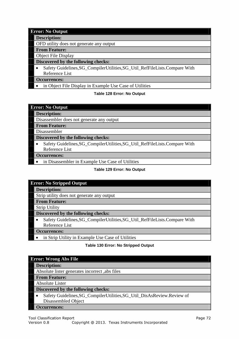
Tool Classification Report Page 72 Version 0.8 Copyright @ 2013. Texas Instruments Incorporated
Error: No Output
Description:
OFD utility does not generate any output
From Feature:
Object File Display
Discovered by the following checks:
Safety Guidelines,SG_CompilerUtilities,SG_Util_RefFileLists.Compare With
Reference List
Occurrences:
in Object File Display in Example Use Case of Utilities
Table 128 Error: No Output
Error: No Output
Description:
Disassembler does not generate any output
From Feature:
Disassembler
Discovered by the following checks:
Safety Guidelines,SG_CompilerUtilities,SG_Util_RefFileLists.Compare With
Reference List
Occurrences:
in Disassembler in Example Use Case of Utilities
Table 129 Error: No Output
Error: No Stripped Output
Description:
Strip utility does not generate any output
From Feature:
Strip Utility
Discovered by the following checks:
Safety Guidelines,SG_CompilerUtilities,SG_Util_RefFileLists.Compare With
Reference List
Occurrences:
in Strip Utility in Example Use Case of Utilities
Table 130 Error: No Stripped Output
Error: Wrong Abs File
Description:
Absolute lister generates incorrect ,abs files
From Feature:
Absolute Lister
Discovered by the following checks:
Safety Guidelines,SG_CompilerUtilities,SG_Util_DisAsReview.Review of
Disassembled Object
Occurrences:

Tool Classification Report Page 73 Version 0.8 Copyright @ 2013. Texas Instruments Incorporated
in Absolute Lister in Example Use Case of Utilities
Table 131 Error: Wrong Abs File
Error: Wrong Listing File
Description:
Cross-reference lister generates an incorrect listing file
From Feature:
Cross-Reference Lister
Discovered by the following checks:
Safety Guidelines,SG_CompilerUtilities,SG_Util_DisAsReview.Review of
Disassembled Object
Occurrences:
in Cross-Reference Lister in Example Use Case of Utilities
Table 132 Error: Wrong Listing File
Error: Wrong Output
Description:
Name utility generates an incorrect output file
From Feature:
Name Utility
Discovered by the following checks:
Safety Guidelines,SG_CompilerUtilities,SG_Util_DisAsReview.Review of
Disassembled Object
Occurrences:
in Name Utility in Example Use Case of Utilities
Table 133 Error: Wrong Output
Error: Wrong Output
Description:
OFD utility generates an incorrect output file
From Feature:
Object File Display
Discovered by the following checks:
Safety Guidelines,SG_CompilerUtilities,SG_Util_DisAsReview.Review of
Disassembled Object
Safety Guidelines,SG_TBD.To Be Defined By User
Occurrences:
in Object File Display in Example Use Case of Utilities
Table 134 Error: Wrong Output
Error: Wrong Source Output
Description:
Disassembler generates an incorrect output file
From Feature:
Disassembler
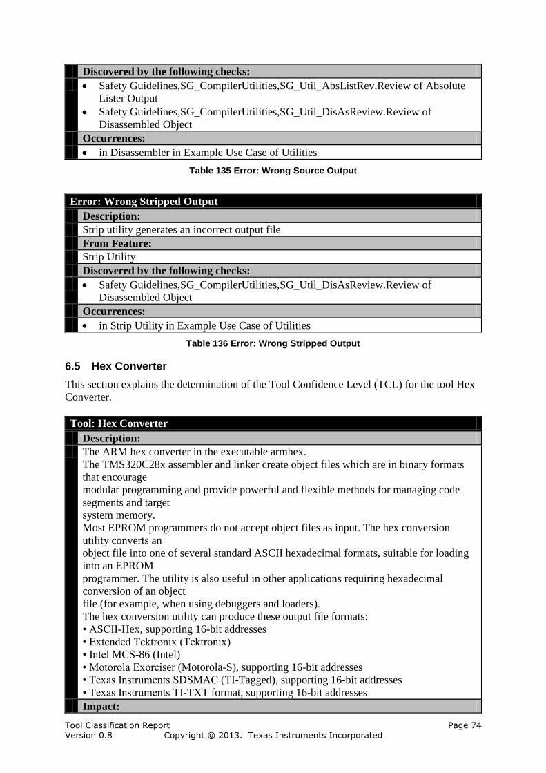
Tool Classification Report Page 74 Version 0.8 Copyright @ 2013. Texas Instruments Incorporated
Discovered by the following checks:
Safety Guidelines,SG_CompilerUtilities,SG_Util_AbsListRev.Review of Absolute
Lister Output
Safety Guidelines,SG_CompilerUtilities,SG_Util_DisAsReview.Review of
Disassembled Object
Occurrences:
in Disassembler in Example Use Case of Utilities
Table 135 Error: Wrong Source Output
Error: Wrong Stripped Output
Description:
Strip utility generates an incorrect output file
From Feature:
Strip Utility
Discovered by the following checks:
Safety Guidelines,SG_CompilerUtilities,SG_Util_DisAsReview.Review of
Disassembled Object
Occurrences:
in Strip Utility in Example Use Case of Utilities
Table 136 Error: Wrong Stripped Output
6.5 Hex Converter
This section explains the determination of the Tool Confidence Level (TCL) for the tool Hex
Converter.
Tool: Hex Converter
Description:
The ARM hex converter in the executable armhex.
The TMS320C28x assembler and linker create object files which are in binary formats
that encourage
modular programming and provide powerful and flexible methods for managing code
segments and target
system memory.
Most EPROM programmers do not accept object files as input. The hex conversion
utility converts an
object file into one of several standard ASCII hexadecimal formats, suitable for loading
into an EPROM
programmer. The utility is also useful in other applications requiring hexadecimal
conversion of an object
file (for example, when using debuggers and loaders).
The hex conversion utility can produce these output file formats:
• ASCII-Hex, supporting 16-bit addresses
• Extended Tektronix (Tektronix)
• Intel MCS-86 (Intel)
• Motorola Exorciser (Motorola-S), supporting 16-bit addresses
• Texas Instruments SDSMAC (TI-Tagged), supporting 16-bit addresses
• Texas Instruments TI-TXT format, supporting 16-bit addresses
Impact:

Tool Classification Report Page 75 Version 0.8 Copyright @ 2013. Texas Instruments Incorporated
TI 2 (Impact)
Tool Confidence Level:
TCL 2
Table 137 Tool: Hex Converter
The tool Hex Converter is modeled with 32 elements which have impact, none of them are
assumptions. In addition there have been modeled 15 features, none of them are assumptions.
Elements Amount (Assumptions)
Use Cases 1 (0)
Checks 2 (0)
Restrictions 0 (0)
Potential Errors 29 (0)
Table 138 Amount of Elements in Tool Hex Converter
6.5.1 Use Cases of Hex Converter
This section describes all analyzed use cases of Hex Converter in separate subsections.
The following use cases of the tool Hex Converter are considered:
1. Example Use Case of Converter, see Section 6.5.1.1
6.5.1.1 Use Case Example Use Case of Converter
This section describes the use case "Example Use Case of Converter".
Use Case: Example Use Case of Converter
Description:
This is just an example use case that shows how a use case is configured by selecting
your required features.
Comment:
Change use according to your needs.
Table 139 Use Case: Example Use Case of Converter
The use case requires 10 features and calls no other use cases.
"Example Use Case of Converter" uses following features:
Boot Table
Create Hex Output
Create Load Image
Memory Image
Sections
Set Entry Point
Set Fill Value
Set ROM Device Width
Set System Memory Width
Use ROMS Directive

Tool Classification Report Page 76 Version 0.8 Copyright @ 2013. Texas Instruments Incorporated
"Example Use Case of Converter" uses following safety guidelines:
SG_Hex_RefFileLists
SG_Hex_Testrun
"Example Use Case of Converter" has the following 0 features that have high error detection
probability:
6.5.2 Required Features of Hex Converter
This section describes all 10 required features of Hex Converter.
The following tables give an overview of the considered features of Hex Converter.
Feature: Boot Table
Description:
-boot
Build a boot table for an on chip loader
Errors:
No Boot Table
No Output
Wrong Boot Table
Table 140 Feature: Boot Table
Feature: Create Hex Output
Description:
-a, -I, -m1, -x, -t
Create hex output file
Errors:
Corrupt Output
No Output
Table 141 Feature: Create Hex Output
Feature: Create Load Image
Description:
--load_image
Errors:
No Image
No Output
Wrong Image
Table 142 Feature: Create Load Image
Feature: Memory Image
Description:
-image
Generating a memory image
Errors:
No Image

Tool Classification Report Page 77 Version 0.8 Copyright @ 2013. Texas Instruments Incorporated
No Output
Wrong Image
Table 143 Feature: Memory Image
Feature: Sections
Description:
Use SECTIONS directive
Errors:
No Output
SECTION Corrupted
SECTIONS Ignored
Table 144 Feature: Sections
Feature: Set Entry Point
Description:
-e
Set entry point
Errors:
No Entry Point
No Output
Wrong Entry Point
Table 145 Feature: Set Entry Point
Feature: Set Fill Value
Description:
-fill
Errors:
No Fill
No Output
Wrong Fill
Table 146 Feature: Set Fill Value
Feature: Set ROM Device Width
Description:
-romwidth
Set ROM device width.
Errors:
No Output
No Romwidth
Wrong Romwidth
Table 147 Feature: Set ROM Device Width
Feature: Set System Memory Width
Description:
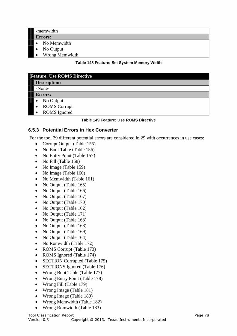
Tool Classification Report Page 78 Version 0.8 Copyright @ 2013. Texas Instruments Incorporated
-memwidth
Errors:
No Memwidth
No Output
Wrong Memwidth
Table 148 Feature: Set System Memory Width
Feature: Use ROMS Directive
Description:
-None-
Errors:
No Output
ROMS Corrupt
ROMS Ignored
Table 149 Feature: Use ROMS Directive
6.5.3 Potential Errors in Hex Converter
For the tool 29 different potential errors are considered in 29 with occurrences in use cases:
Corrupt Output (Table 155)
No Boot Table (Table 156)
No Entry Point (Table 157)
No Fill (Table 158)
No Image (Table 159)
No Image (Table 160)
No Memwidth (Table 161)
No Output (Table 165)
No Output (Table 166)
No Output (Table 167)
No Output (Table 170)
No Output (Table 162)
No Output (Table 171)
No Output (Table 163)
No Output (Table 168)
No Output (Table 169)
No Output (Table 164)
No Romwidth (Table 172)
ROMS Corrupt (Table 173)
ROMS Ignored (Table 174)
SECTION Corrupted (Table 175)
SECTIONS Ignored (Table 176)
Wrong Boot Table (Table 177)
Wrong Entry Point (Table 178)
Wrong Fill (Table 179)
Wrong Image (Table 181)
Wrong Image (Table 180)
Wrong Memwidth (Table 182)
Wrong Romwidth (Table 183)
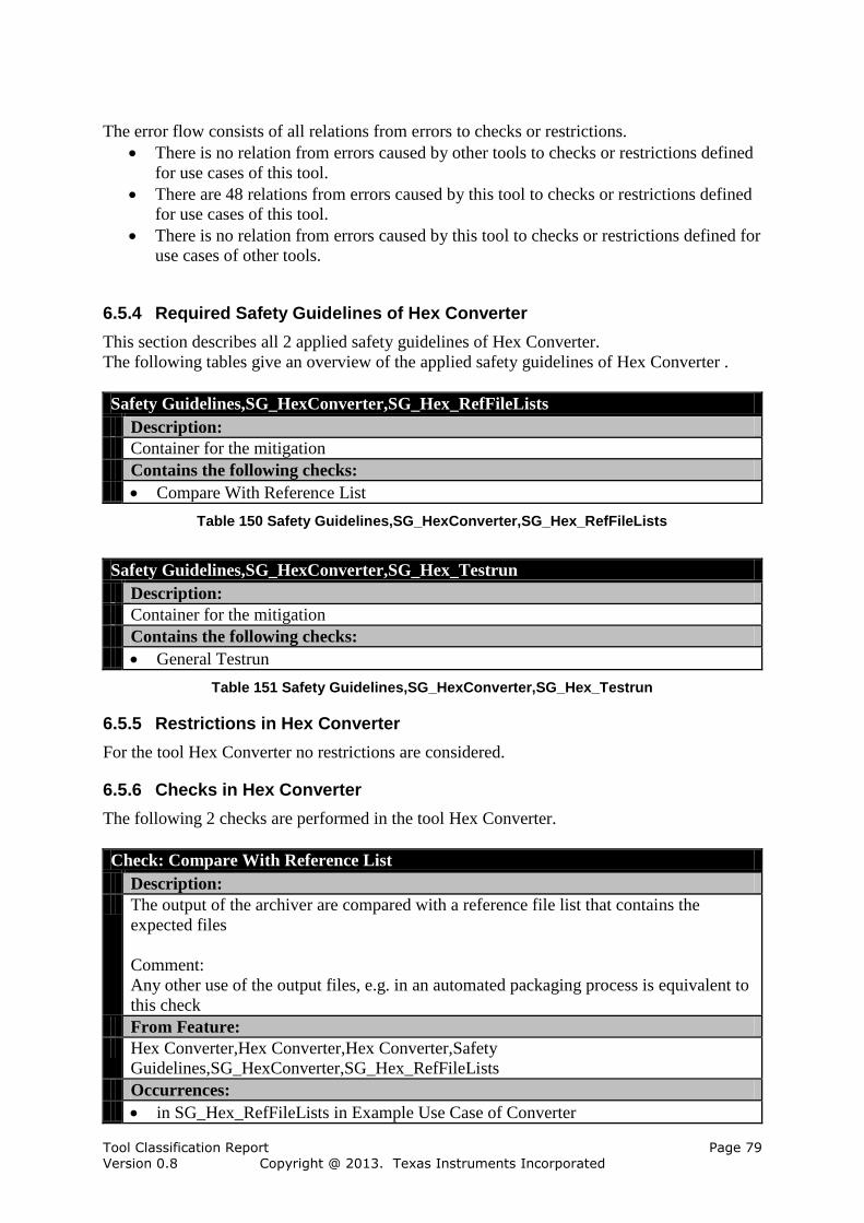
Tool Classification Report Page 79 Version 0.8 Copyright @ 2013. Texas Instruments Incorporated
The error flow consists of all relations from errors to checks or restrictions.
There is no relation from errors caused by other tools to checks or restrictions defined
for use cases of this tool.
There are 48 relations from errors caused by this tool to checks or restrictions defined
for use cases of this tool.
There is no relation from errors caused by this tool to checks or restrictions defined for
use cases of other tools.
6.5.4 Required Safety Guidelines of Hex Converter
This section describes all 2 applied safety guidelines of Hex Converter.
The following tables give an overview of the applied safety guidelines of Hex Converter .
Safety Guidelines,SG_HexConverter,SG_Hex_RefFileLists
Description:
Container for the mitigation
Contains the following checks:
Compare With Reference List
Table 150 Safety Guidelines,SG_HexConverter,SG_Hex_RefFileLists
Safety Guidelines,SG_HexConverter,SG_Hex_Testrun
Description:
Container for the mitigation
Contains the following checks:
General Testrun
Table 151 Safety Guidelines,SG_HexConverter,SG_Hex_Testrun
6.5.5 Restrictions in Hex Converter
For the tool Hex Converter no restrictions are considered.
6.5.6 Checks in Hex Converter
The following 2 checks are performed in the tool Hex Converter.
Check: Compare With Reference List
Description:
The output of the archiver are compared with a reference file list that contains the
expected files
Comment:
Any other use of the output files, e.g. in an automated packaging process is equivalent to
this check
From Feature:
Hex Converter,Hex Converter,Hex Converter,Safety
Guidelines,SG_HexConverter,SG_Hex_RefFileLists
Occurrences:
in SG_Hex_RefFileLists in Example Use Case of Converter
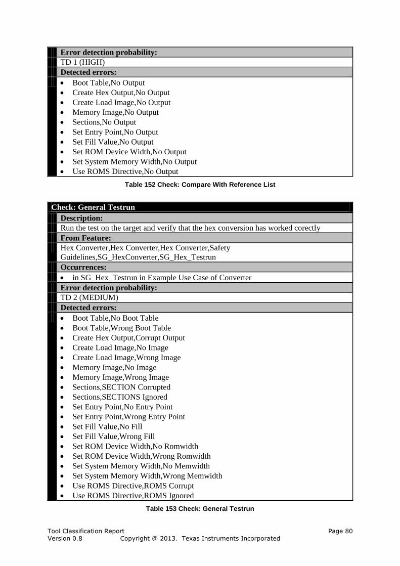
Tool Classification Report Page 80 Version 0.8 Copyright @ 2013. Texas Instruments Incorporated
Error detection probability:
TD 1 (HIGH)
Detected errors:
Boot Table,No Output
Create Hex Output,No Output
Create Load Image,No Output
Memory Image,No Output
Sections,No Output
Set Entry Point,No Output
Set Fill Value,No Output
Set ROM Device Width,No Output
Set System Memory Width,No Output
Use ROMS Directive,No Output
Table 152 Check: Compare With Reference List
Check: General Testrun
Description:
Run the test on the target and verify that the hex conversion has worked corectly
From Feature:
Hex Converter,Hex Converter,Hex Converter,Safety
Guidelines,SG_HexConverter,SG_Hex_Testrun
Occurrences:
in SG_Hex_Testrun in Example Use Case of Converter
Error detection probability:
TD 2 (MEDIUM)
Detected errors:
Boot Table,No Boot Table
Boot Table,Wrong Boot Table
Create Hex Output,Corrupt Output
Create Load Image,No Image
Create Load Image,Wrong Image
Memory Image,No Image
Memory Image,Wrong Image
Sections,SECTION Corrupted
Sections,SECTIONS Ignored
Set Entry Point,No Entry Point
Set Entry Point,Wrong Entry Point
Set Fill Value,No Fill
Set Fill Value,Wrong Fill
Set ROM Device Width,No Romwidth
Set ROM Device Width,Wrong Romwidth
Set System Memory Width,No Memwidth
Set System Memory Width,Wrong Memwidth
Use ROMS Directive,ROMS Corrupt
Use ROMS Directive,ROMS Ignored
Table 153 Check: General Testrun
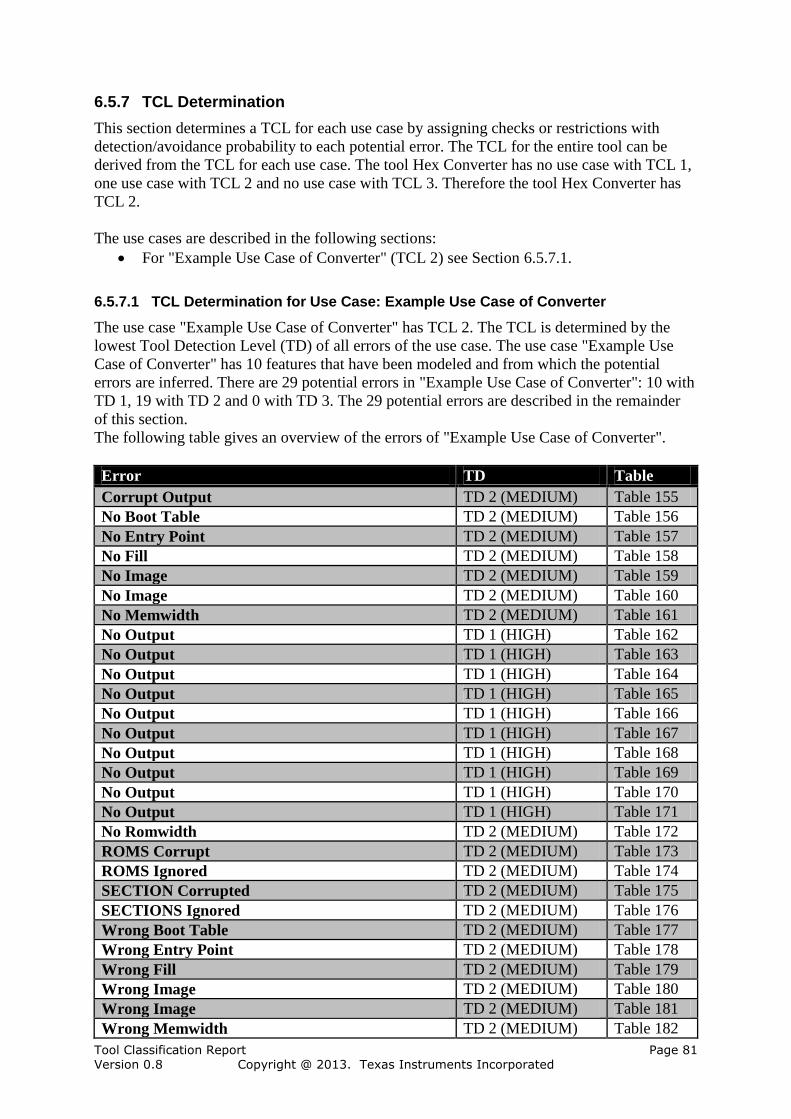
Tool Classification Report Page 81 Version 0.8 Copyright @ 2013. Texas Instruments Incorporated
6.5.7 TCL Determination
This section determines a TCL for each use case by assigning checks or restrictions with
detection/avoidance probability to each potential error. The TCL for the entire tool can be
derived from the TCL for each use case. The tool Hex Converter has no use case with TCL 1,
one use case with TCL 2 and no use case with TCL 3. Therefore the tool Hex Converter has
TCL 2.
The use cases are described in the following sections:
For "Example Use Case of Converter" (TCL 2) see Section 6.5.7.1.
6.5.7.1 TCL Determination for Use Case: Example Use Case of Converter
The use case "Example Use Case of Converter" has TCL 2. The TCL is determined by the
lowest Tool Detection Level (TD) of all errors of the use case. The use case "Example Use
Case of Converter" has 10 features that have been modeled and from which the potential
errors are inferred. There are 29 potential errors in "Example Use Case of Converter": 10 with
TD 1, 19 with TD 2 and 0 with TD 3. The 29 potential errors are described in the remainder
of this section.
The following table gives an overview of the errors of "Example Use Case of Converter".
Error TD Table
Corrupt Output TD 2 (MEDIUM) Table 155
No Boot Table TD 2 (MEDIUM) Table 156
No Entry Point TD 2 (MEDIUM) Table 157
No Fill TD 2 (MEDIUM) Table 158
No Image TD 2 (MEDIUM) Table 159
No Image TD 2 (MEDIUM) Table 160
No Memwidth TD 2 (MEDIUM) Table 161
No Output TD 1 (HIGH) Table 162
No Output TD 1 (HIGH) Table 163
No Output TD 1 (HIGH) Table 164
No Output TD 1 (HIGH) Table 165
No Output TD 1 (HIGH) Table 166
No Output TD 1 (HIGH) Table 167
No Output TD 1 (HIGH) Table 168
No Output TD 1 (HIGH) Table 169
No Output TD 1 (HIGH) Table 170
No Output TD 1 (HIGH) Table 171
No Romwidth TD 2 (MEDIUM) Table 172
ROMS Corrupt TD 2 (MEDIUM) Table 173
ROMS Ignored TD 2 (MEDIUM) Table 174
SECTION Corrupted TD 2 (MEDIUM) Table 175
SECTIONS Ignored TD 2 (MEDIUM) Table 176
Wrong Boot Table TD 2 (MEDIUM) Table 177
Wrong Entry Point TD 2 (MEDIUM) Table 178
Wrong Fill TD 2 (MEDIUM) Table 179
Wrong Image TD 2 (MEDIUM) Table 180
Wrong Image TD 2 (MEDIUM) Table 181
Wrong Memwidth TD 2 (MEDIUM) Table 182
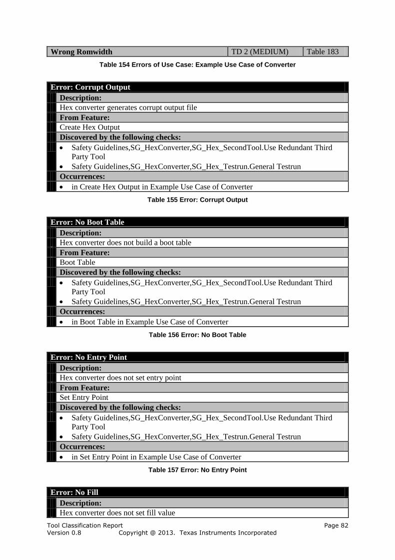
Tool Classification Report Page 82 Version 0.8 Copyright @ 2013. Texas Instruments Incorporated
Wrong Romwidth TD 2 (MEDIUM) Table 183
Table 154 Errors of Use Case: Example Use Case of Converter
Error: Corrupt Output
Description:
Hex converter generates corrupt output file
From Feature:
Create Hex Output
Discovered by the following checks:
Safety Guidelines,SG_HexConverter,SG_Hex_SecondTool.Use Redundant Third
Party Tool
Safety Guidelines,SG_HexConverter,SG_Hex_Testrun.General Testrun
Occurrences:
in Create Hex Output in Example Use Case of Converter
Table 155 Error: Corrupt Output
Error: No Boot Table
Description:
Hex converter does not build a boot table
From Feature:
Boot Table
Discovered by the following checks:
Safety Guidelines,SG_HexConverter,SG_Hex_SecondTool.Use Redundant Third
Party Tool
Safety Guidelines,SG_HexConverter,SG_Hex_Testrun.General Testrun
Occurrences:
in Boot Table in Example Use Case of Converter
Table 156 Error: No Boot Table
Error: No Entry Point
Description:
Hex converter does not set entry point
From Feature:
Set Entry Point
Discovered by the following checks:
Safety Guidelines,SG_HexConverter,SG_Hex_SecondTool.Use Redundant Third
Party Tool
Safety Guidelines,SG_HexConverter,SG_Hex_Testrun.General Testrun
Occurrences:
in Set Entry Point in Example Use Case of Converter
Table 157 Error: No Entry Point
Error: No Fill
Description:
Hex converter does not set fill value

Tool Classification Report Page 83 Version 0.8 Copyright @ 2013. Texas Instruments Incorporated
From Feature:
Set Fill Value
Discovered by the following checks:
Safety Guidelines,SG_HexConverter,SG_Hex_SecondTool.Use Redundant Third
Party Tool
Safety Guidelines,SG_HexConverter,SG_Hex_Testrun.General Testrun
Occurrences:
in Set Fill Value in Example Use Case of Converter
Table 158 Error: No Fill
Error: No Image
Description:
Hex converter does not generate a memory image
From Feature:
Memory Image
Discovered by the following checks:
Safety Guidelines,SG_HexConverter,SG_Hex_SecondTool.Use Redundant Third
Party Tool
Safety Guidelines,SG_HexConverter,SG_Hex_Testrun.General Testrun
Occurrences:
in Memory Image in Example Use Case of Converter
Table 159 Error: No Image
Error: No Image
Description:
Hex converter does not generate a ROM device width
From Feature:
Create Load Image
Discovered by the following checks:
Safety Guidelines,SG_HexConverter,SG_Hex_SecondTool.Use Redundant Third
Party Tool
Safety Guidelines,SG_HexConverter,SG_Hex_Testrun.General Testrun
Occurrences:
in Create Load Image in Example Use Case of Converter
Table 160 Error: No Image
Error: No Memwidth
Description:
Hex converter does not generate a memory width
From Feature:
Set System Memory Width
Discovered by the following checks:
Safety Guidelines,SG_HexConverter,SG_Hex_SecondTool.Use Redundant Third
Party Tool
Safety Guidelines,SG_HexConverter,SG_Hex_Testrun.General Testrun
Occurrences:

Tool Classification Report Page 84 Version 0.8 Copyright @ 2013. Texas Instruments Incorporated
in Set System Memory Width in Example Use Case of Converter
Table 161 Error: No Memwidth
Error: No Output
Description:
Hex converter does not create output file
From Feature:
Memory Image
Discovered by the following checks:
Safety Guidelines,SG_HexConverter,SG_Hex_RefFileLists.Compare With
Reference List
Occurrences:
in Memory Image in Example Use Case of Converter
Table 162 Error: No Output
Error: No Output
Description:
No output generated from hex converter when generating a ROM device width
From Feature:
Create Load Image
Discovered by the following checks:
Safety Guidelines,SG_HexConverter,SG_Hex_RefFileLists.Compare With
Reference List
Occurrences:
in Create Load Image in Example Use Case of Converter
Table 163 Error: No Output
Error: No Output
Description:
Hex converter does not create output file
From Feature:
Create Hex Output
Discovered by the following checks:
Safety Guidelines,SG_HexConverter,SG_Hex_RefFileLists.Compare With
Reference List
Occurrences:
in Create Hex Output in Example Use Case of Converter
Table 164 Error: No Output
Error: No Output
Description:
Hex converter does not create output file
From Feature:
Set Entry Point
Discovered by the following checks:

Tool Classification Report Page 85 Version 0.8 Copyright @ 2013. Texas Instruments Incorporated
Safety Guidelines,SG_HexConverter,SG_Hex_RefFileLists.Compare With
Reference List
Occurrences:
in Set Entry Point in Example Use Case of Converter
Table 165 Error: No Output
Error: No Output
Description:
No output generated from hex converter when building a boot table
From Feature:
Boot Table
Discovered by the following checks:
Safety Guidelines,SG_HexConverter,SG_Hex_RefFileLists.Compare With
Reference List
Occurrences:
in Boot Table in Example Use Case of Converter
Table 166 Error: No Output
Error: No Output
Description:
Hex converter does not create output file
From Feature:
Set Fill Value
Discovered by the following checks:
Safety Guidelines,SG_HexConverter,SG_Hex_RefFileLists.Compare With
Reference List
Occurrences:
in Set Fill Value in Example Use Case of Converter
Table 167 Error: No Output
Error: No Output
Description:
No output generated from hex converter when processing SECTIONS directives
From Feature:
Sections
Discovered by the following checks:
Safety Guidelines,SG_HexConverter,SG_Hex_RefFileLists.Compare With
Reference List
Occurrences:
in Sections in Example Use Case of Converter
Table 168 Error: No Output
Error: No Output
Description:
No output generated from hex converter when generating a memory width

Tool Classification Report Page 86 Version 0.8 Copyright @ 2013. Texas Instruments Incorporated
From Feature:
Set System Memory Width
Discovered by the following checks:
Safety Guidelines,SG_HexConverter,SG_Hex_RefFileLists.Compare With
Reference List
Occurrences:
in Set System Memory Width in Example Use Case of Converter
Table 169 Error: No Output
Error: No Output
Description:
No output generated from hex converter when processing ROMS directives
From Feature:
Use ROMS Directive
Discovered by the following checks:
Safety Guidelines,SG_HexConverter,SG_Hex_RefFileLists.Compare With
Reference List
Occurrences:
in Use ROMS Directive in Example Use Case of Converter
Table 170 Error: No Output
Error: No Output
Description:
No output generated from hex converter when generating a ROM device width
From Feature:
Set ROM Device Width
Discovered by the following checks:
Safety Guidelines,SG_HexConverter,SG_Hex_RefFileLists.Compare With
Reference List
Occurrences:
in Set ROM Device Width in Example Use Case of Converter
Table 171 Error: No Output
Error: No Romwidth
Description:
Hex converter does not generate a ROM device width
From Feature:
Set ROM Device Width
Discovered by the following checks:
Safety Guidelines,SG_HexConverter,SG_Hex_SecondTool.Use Redundant Third
Party Tool
Safety Guidelines,SG_HexConverter,SG_Hex_Testrun.General Testrun
Occurrences:
in Set ROM Device Width in Example Use Case of Converter
Table 172 Error: No Romwidth
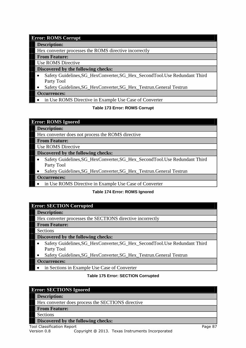
Tool Classification Report Page 87 Version 0.8 Copyright @ 2013. Texas Instruments Incorporated
Error: ROMS Corrupt
Description:
Hex converter processes the ROMS directive incorrectly
From Feature:
Use ROMS Directive
Discovered by the following checks:
Safety Guidelines,SG_HexConverter,SG_Hex_SecondTool.Use Redundant Third
Party Tool
Safety Guidelines,SG_HexConverter,SG_Hex_Testrun.General Testrun
Occurrences:
in Use ROMS Directive in Example Use Case of Converter
Table 173 Error: ROMS Corrupt
Error: ROMS Ignored
Description:
Hex converter does not process the ROMS directive
From Feature:
Use ROMS Directive
Discovered by the following checks:
Safety Guidelines,SG_HexConverter,SG_Hex_SecondTool.Use Redundant Third
Party Tool
Safety Guidelines,SG_HexConverter,SG_Hex_Testrun.General Testrun
Occurrences:
in Use ROMS Directive in Example Use Case of Converter
Table 174 Error: ROMS Ignored
Error: SECTION Corrupted
Description:
Hex converter processes the SECTIONS directive incorrectly
From Feature:
Sections
Discovered by the following checks:
Safety Guidelines,SG_HexConverter,SG_Hex_SecondTool.Use Redundant Third
Party Tool
Safety Guidelines,SG_HexConverter,SG_Hex_Testrun.General Testrun
Occurrences:
in Sections in Example Use Case of Converter
Table 175 Error: SECTION Corrupted
Error: SECTIONS Ignored
Description:
Hex converter does process the SECTIONS directive
From Feature:
Sections
Discovered by the following checks:

Tool Classification Report Page 88 Version 0.8 Copyright @ 2013. Texas Instruments Incorporated
Safety Guidelines,SG_HexConverter,SG_Hex_SecondTool.Use Redundant Third
Party Tool
Safety Guidelines,SG_HexConverter,SG_Hex_Testrun.General Testrun
Occurrences:
in Sections in Example Use Case of Converter
Table 176 Error: SECTIONS Ignored
Error: Wrong Boot Table
Description:
Hex converter builds wrong table
From Feature:
Boot Table
Discovered by the following checks:
Safety Guidelines,SG_HexConverter,SG_Hex_SecondTool.Use Redundant Third
Party Tool
Safety Guidelines,SG_HexConverter,SG_Hex_Testrun.General Testrun
Occurrences:
in Boot Table in Example Use Case of Converter
Table 177 Error: Wrong Boot Table
Error: Wrong Entry Point
Description:
Hex converter sets wrong entry point
From Feature:
Set Entry Point
Discovered by the following checks:
Safety Guidelines,SG_HexConverter,SG_Hex_SecondTool.Use Redundant Third
Party Tool
Safety Guidelines,SG_HexConverter,SG_Hex_Testrun.General Testrun
Occurrences:
in Set Entry Point in Example Use Case of Converter
Table 178 Error: Wrong Entry Point
Error: Wrong Fill
Description:
Hex converter sets wrong fill value
From Feature:
Set Fill Value
Discovered by the following checks:
Safety Guidelines,SG_HexConverter,SG_Hex_SecondTool.Use Redundant Third
Party Tool
Safety Guidelines,SG_HexConverter,SG_Hex_Testrun.General Testrun
Occurrences:
in Set Fill Value in Example Use Case of Converter
Table 179 Error: Wrong Fill
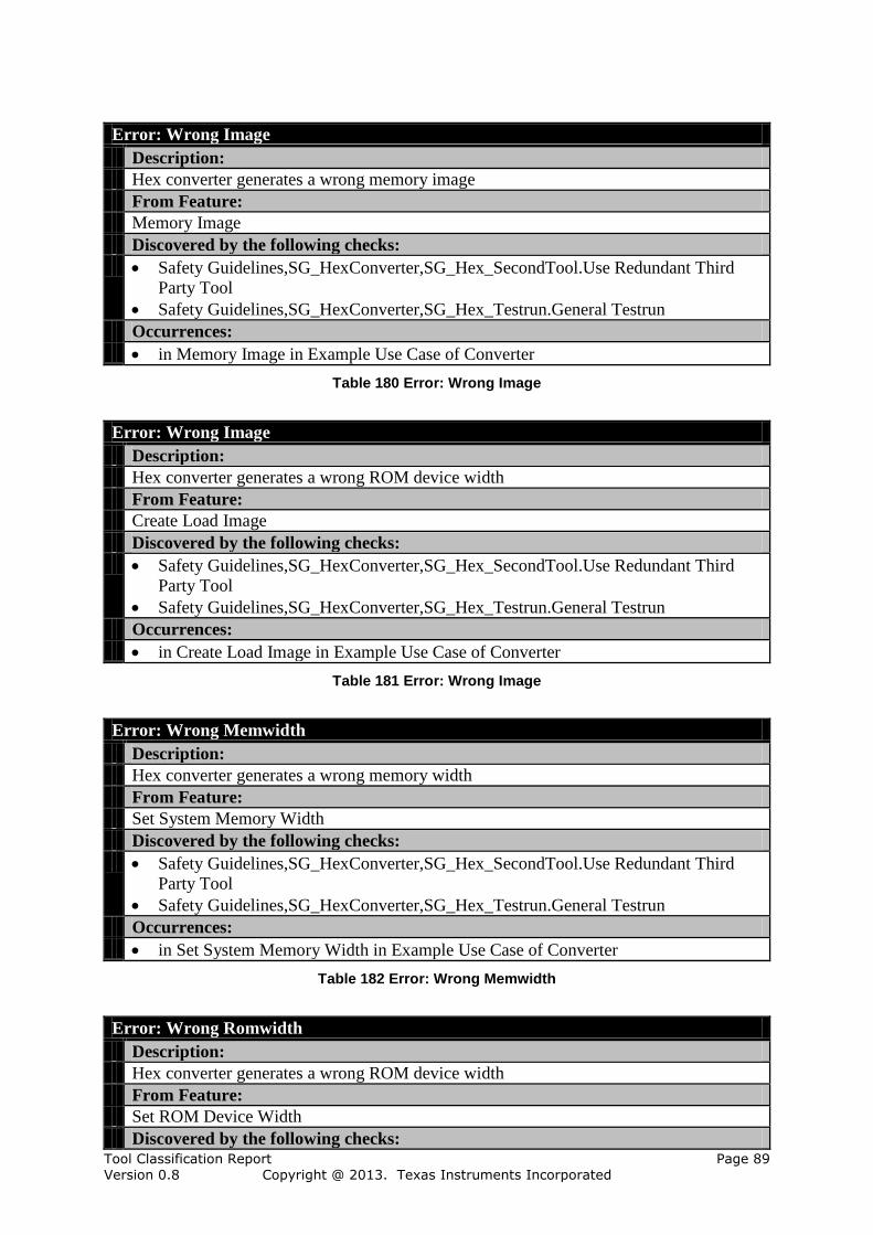
Tool Classification Report Page 89 Version 0.8 Copyright @ 2013. Texas Instruments Incorporated
Error: Wrong Image
Description:
Hex converter generates a wrong memory image
From Feature:
Memory Image
Discovered by the following checks:
Safety Guidelines,SG_HexConverter,SG_Hex_SecondTool.Use Redundant Third
Party Tool
Safety Guidelines,SG_HexConverter,SG_Hex_Testrun.General Testrun
Occurrences:
in Memory Image in Example Use Case of Converter
Table 180 Error: Wrong Image
Error: Wrong Image
Description:
Hex converter generates a wrong ROM device width
From Feature:
Create Load Image
Discovered by the following checks:
Safety Guidelines,SG_HexConverter,SG_Hex_SecondTool.Use Redundant Third
Party Tool
Safety Guidelines,SG_HexConverter,SG_Hex_Testrun.General Testrun
Occurrences:
in Create Load Image in Example Use Case of Converter
Table 181 Error: Wrong Image
Error: Wrong Memwidth
Description:
Hex converter generates a wrong memory width
From Feature:
Set System Memory Width
Discovered by the following checks:
Safety Guidelines,SG_HexConverter,SG_Hex_SecondTool.Use Redundant Third
Party Tool
Safety Guidelines,SG_HexConverter,SG_Hex_Testrun.General Testrun
Occurrences:
in Set System Memory Width in Example Use Case of Converter
Table 182 Error: Wrong Memwidth
Error: Wrong Romwidth
Description:
Hex converter generates a wrong ROM device width
From Feature:
Set ROM Device Width
Discovered by the following checks:

Tool Classification Report Page 90 Version 0.8 Copyright @ 2013. Texas Instruments Incorporated
Safety Guidelines,SG_HexConverter,SG_Hex_SecondTool.Use Redundant Third
Party Tool
Safety Guidelines,SG_HexConverter,SG_Hex_Testrun.General Testrun
Occurrences:
in Set ROM Device Width in Example Use Case of Converter
Table 183 Error: Wrong Romwidth
6.6 Linker
This section explains the determination of the Tool Confidence Level (TCL) for the tool
Linker.
Tool: Linker
Description:
The ARM linker in the executable armlnk
Impact:
TI 2 (Impact)
Tool Confidence Level:
TCL 3
Table 184 Tool: Linker
The tool Linker is modeled with 97 elements which have impact, none of them are
assumptions. In addition there have been modeled 45 features, none of them are assumptions.
Elements Amount (Assumptions)
Use Cases 1 (0)
Checks 2 (0)
Restrictions 0 (0)
Potential Errors 94 (0)
Table 185 Amount of Elements in Tool Linker
6.6.1 Use Cases of Linker
This section describes all analyzed use cases of Linker in separate subsections.
The following use cases of the tool Linker are considered:
1. Example Use Case of Linker, see Section 6.6.1.1
6.6.1.1 Use Case Example Use Case of Linker
This section describes the use case "Example Use Case of Linker".
Use Case: Example Use Case of Linker
Description:
This is just an example use case that shows how a use case is configured by selecting
your required features.
Comment:
Change use according to your needs.
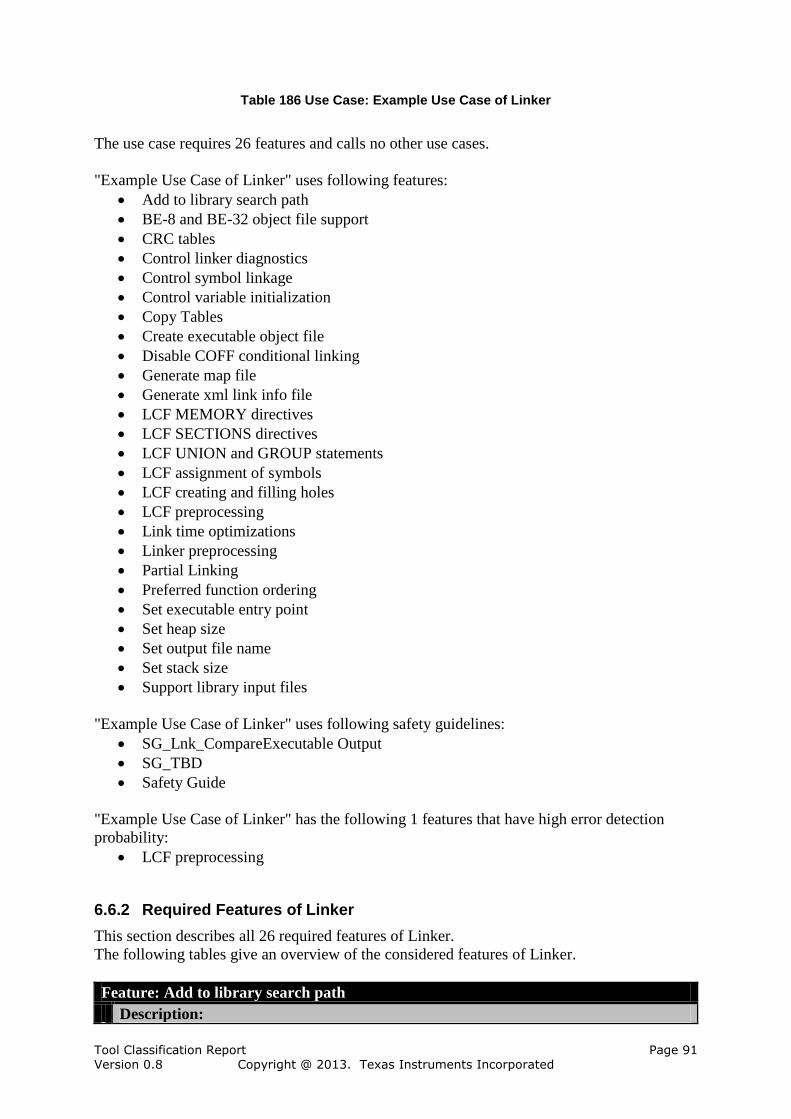
Tool Classification Report Page 91 Version 0.8 Copyright @ 2013. Texas Instruments Incorporated
Table 186 Use Case: Example Use Case of Linker
The use case requires 26 features and calls no other use cases.
"Example Use Case of Linker" uses following features:
Add to library search path
BE-8 and BE-32 object file support
CRC tables
Control linker diagnostics
Control symbol linkage
Control variable initialization
Copy Tables
Create executable object file
Disable COFF conditional linking
Generate map file
Generate xml link info file
LCF MEMORY directives
LCF SECTIONS directives
LCF UNION and GROUP statements
LCF assignment of symbols
LCF creating and filling holes
LCF preprocessing
Link time optimizations
Linker preprocessing
Partial Linking
Preferred function ordering
Set executable entry point
Set heap size
Set output file name
Set stack size
Support library input files
"Example Use Case of Linker" uses following safety guidelines:
SG_Lnk_CompareExecutable Output
SG_TBD
Safety Guide
"Example Use Case of Linker" has the following 1 features that have high error detection
probability:
LCF preprocessing
6.6.2 Required Features of Linker
This section describes all 26 required features of Linker.
The following tables give an overview of the considered features of Linker.
Feature: Add to library search path
Description:

Tool Classification Report Page 92 Version 0.8 Copyright @ 2013. Texas Instruments Incorporated
-l
Errors:
Change behavior
No output
Paths not used
Wrong paths
Table 187 Feature: Add to library search path
Feature: BE-8 and BE-32 object file support
Description:
-be8, -be32
Errors:
Change Behavior
Incorrect Objects Used
No Output
Table 188 Feature: BE-8 and BE-32 object file support
Feature: Control linker diagnostics
Description:
--diag_error, --diag_remark, --diag_warning, --diag_suppress, --warn_sections
Errors:
Change Behavior
No Diagnostics
No Output
Wrong Diagnostics
Table 189 Feature: Control linker diagnostics
Feature: Control symbol linkage
Description:
--globalize, --hide, --make_global, --make_static, --symbol_map
Errors:
Change Behavior
No Output
No Symbol Control
Wrong Symbol Control
Table 190 Feature: Control symbol linkage
Feature: Control variable initialization
Description:
--rom_model or -c, --ram_model or -cr
Errors:
Change behavior
No initialization
No output
Wrong initialization

Tool Classification Report Page 93 Version 0.8 Copyright @ 2013. Texas Instruments Incorporated
Table 191 Feature: Control variable initialization
Feature: Copy Tables
Description:
Linker generated copy tables
Errors:
Change Behavior
Copy Tables Defect
Copy Tables Ignored
No Output
Table 192 Feature: Copy Tables
Feature: CRC tables
Description:
Linker generated CRC tables
Errors:
Change Behavior
Incorrect CRC
No CRC
No Output
Table 193 Feature: CRC tables
Feature: Create executable object file
Description:
none, -a
Errors:
Change behavior
No executable
Wrong executable
Table 194 Feature: Create executable object file
Feature: Disable COFF conditional linking
Description:
-j, --disable_clink
Errors:
Change Behavior
No Disabling
No Output
Table 195 Feature: Disable COFF conditional linking
Feature: Generate map file
Description:
-m
Errors:
Change behavior

Tool Classification Report Page 94 Version 0.8 Copyright @ 2013. Texas Instruments Incorporated
No map file
No output
Wrong map file
Table 196 Feature: Generate map file
Feature: Generate xml link info file
Description:
--xml_link_info
Errors:
Change behavior
No info file
No output
Wrong info file
Table 197 Feature: Generate xml link info file
Feature: LCF assignment of symbols
Description:
Linker command file assignment of symbols
Errors:
Assignment Defect
Change Behavior
Igonre Assignment
No Output
Table 198 Feature: LCF assignment of symbols
Feature: LCF creating and filling holes
Description:
Linker command file creating and filling holes
Errors:
Change Behavior
Hole Filling Defect
Ignore Hole Filling
No Output
Table 199 Feature: LCF creating and filling holes
Feature: LCF MEMORY directives
Description:
Linker command file MEMORY directives
Errors:
Change Behavior
Ignore MEMORY Directive
MEMORY Directive Defect
No Output
Table 200 Feature: LCF MEMORY directives
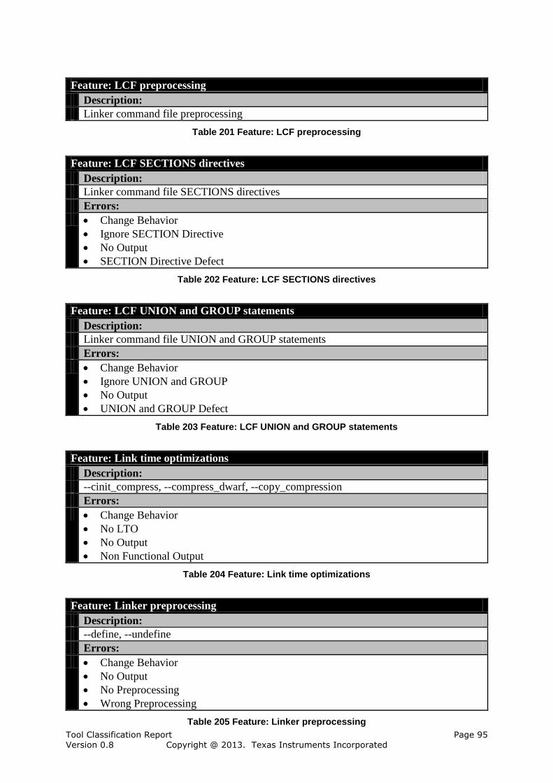
Tool Classification Report Page 95 Version 0.8 Copyright @ 2013. Texas Instruments Incorporated
Feature: LCF preprocessing
Description:
Linker command file preprocessing
Table 201 Feature: LCF preprocessing
Feature: LCF SECTIONS directives
Description:
Linker command file SECTIONS directives
Errors:
Change Behavior
Ignore SECTION Directive
No Output
SECTION Directive Defect
Table 202 Feature: LCF SECTIONS directives
Feature: LCF UNION and GROUP statements
Description:
Linker command file UNION and GROUP statements
Errors:
Change Behavior
Ignore UNION and GROUP
No Output
UNION and GROUP Defect
Table 203 Feature: LCF UNION and GROUP statements
Feature: Link time optimizations
Description:
--cinit_compress, --compress_dwarf, --copy_compression
Errors:
Change Behavior
No LTO
No Output
Non Functional Output
Table 204 Feature: Link time optimizations
Feature: Linker preprocessing
Description:
--define, --undefine
Errors:
Change Behavior
No Output
No Preprocessing
Wrong Preprocessing
Table 205 Feature: Linker preprocessing
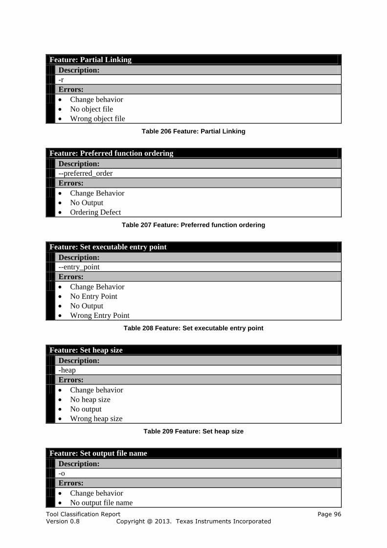
Tool Classification Report Page 96 Version 0.8 Copyright @ 2013. Texas Instruments Incorporated
Feature: Partial Linking
Description:
-r
Errors:
Change behavior
No object file
Wrong object file
Table 206 Feature: Partial Linking
Feature: Preferred function ordering
Description:
--preferred_order
Errors:
Change Behavior
No Output
Ordering Defect
Table 207 Feature: Preferred function ordering
Feature: Set executable entry point
Description:
--entry_point
Errors:
Change Behavior
No Entry Point
No Output
Wrong Entry Point
Table 208 Feature: Set executable entry point
Feature: Set heap size
Description:
-heap
Errors:
Change behavior
No heap size
No output
Wrong heap size
Table 209 Feature: Set heap size
Feature: Set output file name
Description:
-o
Errors:
Change behavior
No output file name
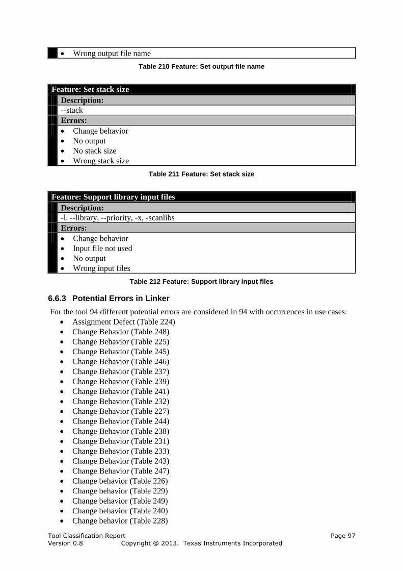
Tool Classification Report Page 97 Version 0.8 Copyright @ 2013. Texas Instruments Incorporated
Wrong output file name
Table 210 Feature: Set output file name
Feature: Set stack size
Description:
--stack
Errors:
Change behavior
No output
No stack size
Wrong stack size
Table 211 Feature: Set stack size
Feature: Support library input files
Description:
-l. --library, --priority, -x, -scanlibs
Errors:
Change behavior
Input file not used
No output
Wrong input files
Table 212 Feature: Support library input files
6.6.3 Potential Errors in Linker
For the tool 94 different potential errors are considered in 94 with occurrences in use cases:
Assignment Defect (Table 224)
Change Behavior (Table 248)
Change Behavior (Table 225)
Change Behavior (Table 245)
Change Behavior (Table 246)
Change Behavior (Table 237)
Change Behavior (Table 239)
Change Behavior (Table 241)
Change Behavior (Table 232)
Change Behavior (Table 227)
Change Behavior (Table 244)
Change Behavior (Table 238)
Change Behavior (Table 231)
Change Behavior (Table 233)
Change Behavior (Table 243)
Change Behavior (Table 247)
Change behavior (Table 226)
Change behavior (Table 229)
Change behavior (Table 249)
Change behavior (Table 240)
Change behavior (Table 228)
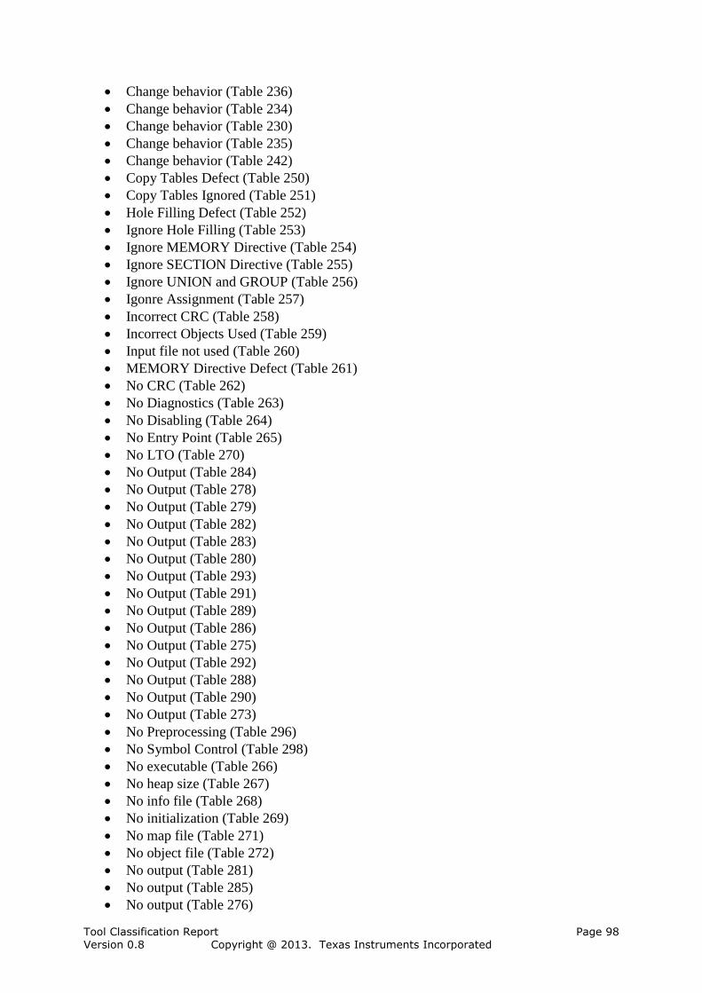
Tool Classification Report Page 98 Version 0.8 Copyright @ 2013. Texas Instruments Incorporated
Change behavior (Table 236)
Change behavior (Table 234)
Change behavior (Table 230)
Change behavior (Table 235)
Change behavior (Table 242)
Copy Tables Defect (Table 250)
Copy Tables Ignored (Table 251)
Hole Filling Defect (Table 252)
Ignore Hole Filling (Table 253)
Ignore MEMORY Directive (Table 254)
Ignore SECTION Directive (Table 255)
Ignore UNION and GROUP (Table 256)
Igonre Assignment (Table 257)
Incorrect CRC (Table 258)
Incorrect Objects Used (Table 259)
Input file not used (Table 260)
MEMORY Directive Defect (Table 261)
No CRC (Table 262)
No Diagnostics (Table 263)
No Disabling (Table 264)
No Entry Point (Table 265)
No LTO (Table 270)
No Output (Table 284)
No Output (Table 278)
No Output (Table 279)
No Output (Table 282)
No Output (Table 283)
No Output (Table 280)
No Output (Table 293)
No Output (Table 291)
No Output (Table 289)
No Output (Table 286)
No Output (Table 275)
No Output (Table 292)
No Output (Table 288)
No Output (Table 290)
No Output (Table 273)
No Preprocessing (Table 296)
No Symbol Control (Table 298)
No executable (Table 266)
No heap size (Table 267)
No info file (Table 268)
No initialization (Table 269)
No map file (Table 271)
No object file (Table 272)
No output (Table 281)
No output (Table 285)
No output (Table 276)

Tool Classification Report Page 99 Version 0.8 Copyright @ 2013. Texas Instruments Incorporated
No output (Table 294)
No output (Table 287)
No output (Table 277)
No output (Table 274)
No output file name (Table 295)
No stack size (Table 297)
Non Functional Output (Table 299)
Ordering Defect (Table 300)
Paths not used (Table 301)
SECTION Directive Defect (Table 302)
UNION and GROUP Defect (Table 303)
Wrong Diagnostics (Table 304)
Wrong Entry Point (Table 305)
Wrong Preprocessing (Table 315)
Wrong Symbol Control (Table 317)
Wrong executable (Table 306)
Wrong heap size (Table 307)
Wrong info file (Table 308)
Wrong initialization (Table 309)
Wrong input files (Table 310)
Wrong map file (Table 311)
Wrong object file (Table 312)
Wrong output file name (Table 313)
Wrong paths (Table 314)
Wrong stack size (Table 316)
The error flow consists of all relations from errors to checks or restrictions.
There is no relation from errors caused by other tools to checks or restrictions defined
for use cases of this tool.
There are 132 relations from errors caused by this tool to checks or restrictions defined
for use cases of this tool.
There is no relation from errors caused by this tool to checks or restrictions defined for
use cases of other tools.
There are 3 errors caused by this tool without any relation to checks or restrictions.
The following 3 error occurrences of Linker have no relation to any check or restriction:
Hole Filling Defect (Table 252)
Ignore MEMORY Directive (Table 254)
Wrong executable (Table 306)
6.6.4 Required Safety Guidelines of Linker
This section describes all 8 applied safety guidelines of Linker.
The following tables give an overview of the applied safety guidelines of Linker .
Safety Guide
Description:
-None-

Tool Classification Report Page 100 Version 0.8 Copyright @ 2013. Texas Instruments Incorporated
Table 213 Safety Guide
Safety Guide,SG_Linker
Description:
Safety guidelines for the linker feature
Table 214 Safety Guide,SG_Linker
Safety Guide,SG_Linker,SG_Lnk_CompareExecutable Output
Description:
Container for the safety guideline
Contains the following checks:
Linking with and without setting output file name
Table 215 Safety Guide,SG_Linker,SG_Lnk_CompareExecutable Output
Safety Guide,SG_Linker,SG_Lnk_CompOutputList
Description:
Guideline to compare the output file lists
Contains the following checks:
Compare Linker Output Files with Reference File List
Table 216 Safety Guide,SG_Linker,SG_Lnk_CompOutputList
Safety Guide,SG_Linker,SG_Lnk_ReviewDissaembler
Description:
Guideline to review the dissasembled output
Contains the following checks:
Review with Disassembler
Table 217 Safety Guide,SG_Linker,SG_Lnk_ReviewDissaembler
Safety Guide,SG_Linker,SG_Lnk_ReviewLinkInfo
Description:
Guideline to apply the review of the XML link file information
Contains the following checks:
Review Against Link Info
Table 218 Safety Guide,SG_Linker,SG_Lnk_ReviewLinkInfo
Safety Guide,SG_Linker,SG_Lnk_ReviewMapfileSimple
Description:
Guideline for reviewing the mapfile for simple elements that can be easy detected
Contains the following checks:
Review Mapfile
Table 219 Safety Guide,SG_Linker,SG_Lnk_ReviewMapfileSimple
Safety Guide,SG_TBD

Tool Classification Report Page 101 Version 0.8 Copyright @ 2013. Texas Instruments Incorporated
Description:
Container for safety guidelines that hvae to be defined from the user in his procss
Contains the following checks:
To Be Defined By User
Table 220 Safety Guide,SG_TBD
6.6.5 Restrictions in Linker
For the tool Linker no restrictions are considered.
6.6.6 Checks in Linker
The following 2 checks are performed in the tool Linker.
Check: Linking with and without setting output file name
Description:
And compare the executable using binary compare or test
From Feature:
Linker,Linker,Linker,Safety Guide,SG_Linker,SG_Lnk_CompareExecutable Output
Occurrences:
in SG_Lnk_CompareExecutable Output in Example Use Case of Linker
Error detection probability:
TD 1 (HIGH)
Detected errors:
Set output file name,Change behavior
Table 221 Check: Linking with and without setting output file name
Check: To Be Defined By User
Description:
This check has to be defined from the user to detect the assigned errors with a HIGH
probability
A high probability is usually achieved by autmated scripts or other tools that produce
comparable results and the results are compared with the results of this tool.
Comment:
Currently we do not have tests for that feature, but we are working on them in order to
reduce the tasks for the user to implement this check.
From Feature:
Linker,Linker,Safety Guide,SG_TBD
Occurrences:
in SG_TBD in Example Use Case of Linker
Error detection probability:
TD 1 (HIGH)
Detected errors:
CRC tables,Incorrect CRC
CRC tables,No CRC
CRC tables,No Output
Copy Tables,Copy Tables Defect
Copy Tables,Copy Tables Ignored
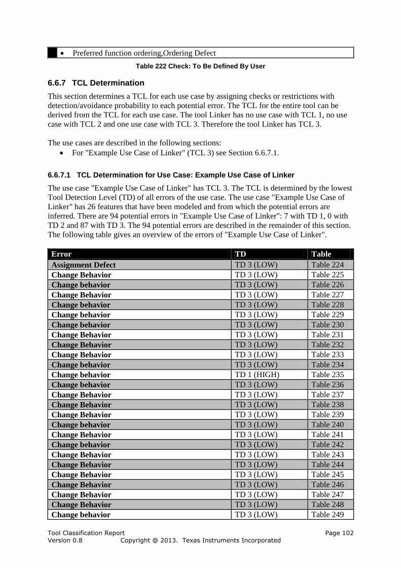
Tool Classification Report Page 102 Version 0.8 Copyright @ 2013. Texas Instruments Incorporated
Preferred function ordering,Ordering Defect
Table 222 Check: To Be Defined By User
6.6.7 TCL Determination
This section determines a TCL for each use case by assigning checks or restrictions with
detection/avoidance probability to each potential error. The TCL for the entire tool can be
derived from the TCL for each use case. The tool Linker has no use case with TCL 1, no use
case with TCL 2 and one use case with TCL 3. Therefore the tool Linker has TCL 3.
The use cases are described in the following sections:
For "Example Use Case of Linker" (TCL 3) see Section 6.6.7.1.
6.6.7.1 TCL Determination for Use Case: Example Use Case of Linker
The use case "Example Use Case of Linker" has TCL 3. The TCL is determined by the lowest
Tool Detection Level (TD) of all errors of the use case. The use case "Example Use Case of
Linker" has 26 features that have been modeled and from which the potential errors are
inferred. There are 94 potential errors in "Example Use Case of Linker": 7 with TD 1, 0 with
TD 2 and 87 with TD 3. The 94 potential errors are described in the remainder of this section.
The following table gives an overview of the errors of "Example Use Case of Linker".
Error TD Table
Assignment Defect TD 3 (LOW) Table 224
Change Behavior TD 3 (LOW) Table 225
Change behavior TD 3 (LOW) Table 226
Change Behavior TD 3 (LOW) Table 227
Change behavior TD 3 (LOW) Table 228
Change behavior TD 3 (LOW) Table 229
Change behavior TD 3 (LOW) Table 230
Change Behavior TD 3 (LOW) Table 231
Change Behavior TD 3 (LOW) Table 232
Change Behavior TD 3 (LOW) Table 233
Change behavior TD 3 (LOW) Table 234
Change behavior TD 1 (HIGH) Table 235
Change behavior TD 3 (LOW) Table 236
Change Behavior TD 3 (LOW) Table 237
Change Behavior TD 3 (LOW) Table 238
Change Behavior TD 3 (LOW) Table 239
Change behavior TD 3 (LOW) Table 240
Change Behavior TD 3 (LOW) Table 241
Change behavior TD 3 (LOW) Table 242
Change Behavior TD 3 (LOW) Table 243
Change Behavior TD 3 (LOW) Table 244
Change Behavior TD 3 (LOW) Table 245
Change Behavior TD 3 (LOW) Table 246
Change Behavior TD 3 (LOW) Table 247
Change Behavior TD 3 (LOW) Table 248
Change behavior TD 3 (LOW) Table 249

Tool Classification Report Page 103 Version 0.8 Copyright @ 2013. Texas Instruments Incorporated
Copy Tables Defect TD 1 (HIGH) Table 250
Copy Tables Ignored TD 1 (HIGH) Table 251
Hole Filling Defect TD 3 (LOW) Table 252
Ignore Hole Filling TD 3 (LOW) Table 253
Ignore MEMORY Directive TD 3 (LOW) Table 254
Ignore SECTION Directive TD 3 (LOW) Table 255
Ignore UNION and GROUP TD 3 (LOW) Table 256
Igonre Assignment TD 3 (LOW) Table 257
Incorrect CRC TD 1 (HIGH) Table 258
Incorrect Objects Used TD 3 (LOW) Table 259
Input file not used TD 3 (LOW) Table 260
MEMORY Directive Defect TD 3 (LOW) Table 261
No CRC TD 1 (HIGH) Table 262
No Diagnostics TD 3 (LOW) Table 263
No Disabling TD 3 (LOW) Table 264
No Entry Point TD 3 (LOW) Table 265
No executable TD 3 (LOW) Table 266
No heap size TD 3 (LOW) Table 267
No info file TD 3 (LOW) Table 268
No initialization TD 3 (LOW) Table 269
No LTO TD 3 (LOW) Table 270
No map file TD 3 (LOW) Table 271
No object file TD 3 (LOW) Table 272
No Output TD 3 (LOW) Table 273
No output TD 3 (LOW) Table 274
No Output TD 3 (LOW) Table 275
No output TD 3 (LOW) Table 276
No output TD 3 (LOW) Table 277
No Output TD 3 (LOW) Table 278
No Output TD 3 (LOW) Table 279
No Output TD 3 (LOW) Table 280
No output TD 3 (LOW) Table 281
No Output TD 3 (LOW) Table 282
No Output TD 3 (LOW) Table 283
No Output TD 3 (LOW) Table 284
No output TD 3 (LOW) Table 285
No Output TD 3 (LOW) Table 286
No output TD 3 (LOW) Table 287
No Output TD 3 (LOW) Table 288
No Output TD 3 (LOW) Table 289
No Output TD 3 (LOW) Table 290
No Output TD 3 (LOW) Table 291
No Output TD 3 (LOW) Table 292
No Output TD 1 (HIGH) Table 293
No output TD 3 (LOW) Table 294
No output file name TD 3 (LOW) Table 295
No Preprocessing TD 3 (LOW) Table 296
No stack size TD 3 (LOW) Table 297
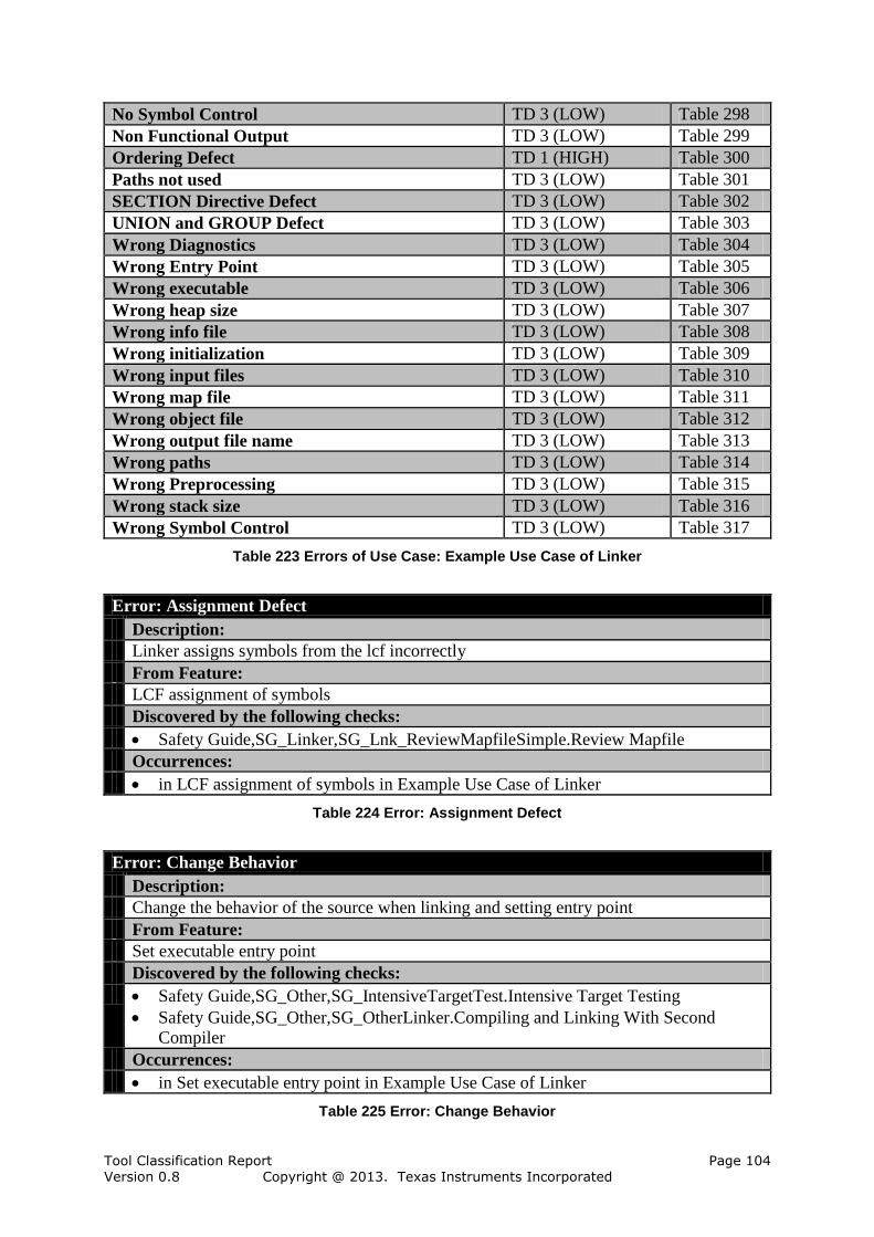
Tool Classification Report Page 104 Version 0.8 Copyright @ 2013. Texas Instruments Incorporated
No Symbol Control TD 3 (LOW) Table 298
Non Functional Output TD 3 (LOW) Table 299
Ordering Defect TD 1 (HIGH) Table 300
Paths not used TD 3 (LOW) Table 301
SECTION Directive Defect TD 3 (LOW) Table 302
UNION and GROUP Defect TD 3 (LOW) Table 303
Wrong Diagnostics TD 3 (LOW) Table 304
Wrong Entry Point TD 3 (LOW) Table 305
Wrong executable TD 3 (LOW) Table 306
Wrong heap size TD 3 (LOW) Table 307
Wrong info file TD 3 (LOW) Table 308
Wrong initialization TD 3 (LOW) Table 309
Wrong input files TD 3 (LOW) Table 310
Wrong map file TD 3 (LOW) Table 311
Wrong object file TD 3 (LOW) Table 312
Wrong output file name TD 3 (LOW) Table 313
Wrong paths TD 3 (LOW) Table 314
Wrong Preprocessing TD 3 (LOW) Table 315
Wrong stack size TD 3 (LOW) Table 316
Wrong Symbol Control TD 3 (LOW) Table 317
Table 223 Errors of Use Case: Example Use Case of Linker
Error: Assignment Defect
Description:
Linker assigns symbols from the lcf incorrectly
From Feature:
LCF assignment of symbols
Discovered by the following checks:
Safety Guide,SG_Linker,SG_Lnk_ReviewMapfileSimple.Review Mapfile
Occurrences:
in LCF assignment of symbols in Example Use Case of Linker
Table 224 Error: Assignment Defect
Error: Change Behavior
Description:
Change the behavior of the source when linking and setting entry point
From Feature:
Set executable entry point
Discovered by the following checks:
Safety Guide,SG_Other,SG_IntensiveTargetTest.Intensive Target Testing
Safety Guide,SG_Other,SG_OtherLinker.Compiling and Linking With Second
Compiler
Occurrences:
in Set executable entry point in Example Use Case of Linker
Table 225 Error: Change Behavior

Tool Classification Report Page 105 Version 0.8 Copyright @ 2013. Texas Instruments Incorporated
Error: Change behavior
Description:
Change the behavior of the source when linking and setting a stack size
From Feature:
Set stack size
Discovered by the following checks:
Safety Guide,SG_Other,SG_IntensiveTargetTest.Intensive Target Testing
Safety Guide,SG_Other,SG_OtherLinker.Compiling and Linking With Second
Compiler
Occurrences:
in Set stack size in Example Use Case of Linker
Table 226 Error: Change behavior
Error: Change Behavior
Description:
Change the behavior of the source when linking with lcf assigned symbols
From Feature:
LCF assignment of symbols
Discovered by the following checks:
Safety Guide,SG_Other,SG_IntensiveTargetTest.Intensive Target Testing
Safety Guide,SG_Other,SG_OtherLinker.Compiling and Linking With Second
Compiler
Occurrences:
in LCF assignment of symbols in Example Use Case of Linker
Table 227 Error: Change Behavior
Error: Change behavior
Description:
Change the behavior of the source when linking and setting a heap size
From Feature:
Set heap size
Discovered by the following checks:
Safety Guide,SG_Other,SG_IntensiveTargetTest.Intensive Target Testing
Safety Guide,SG_Other,SG_OtherLinker.Compiling and Linking With Second
Compiler
Occurrences:
in Set heap size in Example Use Case of Linker
Table 228 Error: Change behavior
Error: Change behavior
Description:
Change the behavior of the source when linking and using library input files
From Feature:
Support library input files
Discovered by the following checks:
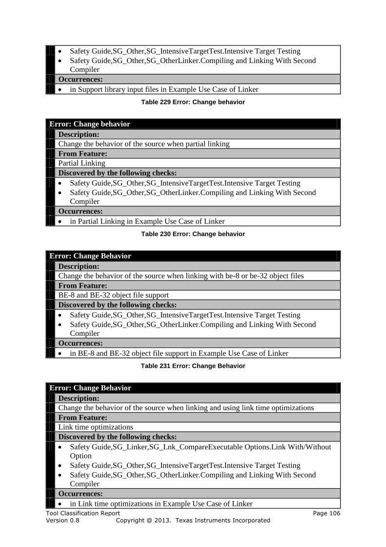
Tool Classification Report Page 106 Version 0.8 Copyright @ 2013. Texas Instruments Incorporated
Safety Guide,SG_Other,SG_IntensiveTargetTest.Intensive Target Testing
Safety Guide,SG_Other,SG_OtherLinker.Compiling and Linking With Second
Compiler
Occurrences:
in Support library input files in Example Use Case of Linker
Table 229 Error: Change behavior
Error: Change behavior
Description:
Change the behavior of the source when partial linking
From Feature:
Partial Linking
Discovered by the following checks:
Safety Guide,SG_Other,SG_IntensiveTargetTest.Intensive Target Testing
Safety Guide,SG_Other,SG_OtherLinker.Compiling and Linking With Second
Compiler
Occurrences:
in Partial Linking in Example Use Case of Linker
Table 230 Error: Change behavior
Error: Change Behavior
Description:
Change the behavior of the source when linking with be-8 or be-32 object files
From Feature:
BE-8 and BE-32 object file support
Discovered by the following checks:
Safety Guide,SG_Other,SG_IntensiveTargetTest.Intensive Target Testing
Safety Guide,SG_Other,SG_OtherLinker.Compiling and Linking With Second
Compiler
Occurrences:
in BE-8 and BE-32 object file support in Example Use Case of Linker
Table 231 Error: Change Behavior
Error: Change Behavior
Description:
Change the behavior of the source when linking and using link time optimizations
From Feature:
Link time optimizations
Discovered by the following checks:
Safety Guide,SG_Linker,SG_Lnk_CompareExecutable Options.Link With/Without
Option
Safety Guide,SG_Other,SG_IntensiveTargetTest.Intensive Target Testing
Safety Guide,SG_Other,SG_OtherLinker.Compiling and Linking With Second
Compiler
Occurrences:
in Link time optimizations in Example Use Case of Linker
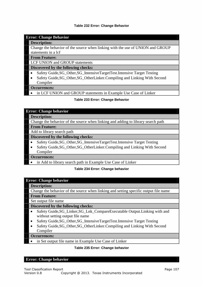
Tool Classification Report Page 107 Version 0.8 Copyright @ 2013. Texas Instruments Incorporated
Table 232 Error: Change Behavior
Error: Change Behavior
Description:
Change the behavior of the source when linking with the use of UNION and GROUP
statements in a lcf
From Feature:
LCF UNION and GROUP statements
Discovered by the following checks:
Safety Guide,SG_Other,SG_IntensiveTargetTest.Intensive Target Testing
Safety Guide,SG_Other,SG_OtherLinker.Compiling and Linking With Second
Compiler
Occurrences:
in LCF UNION and GROUP statements in Example Use Case of Linker
Table 233 Error: Change Behavior
Error: Change behavior
Description:
Change the behavior of the source when linking and adding to library search path
From Feature:
Add to library search path
Discovered by the following checks:
Safety Guide,SG_Other,SG_IntensiveTargetTest.Intensive Target Testing
Safety Guide,SG_Other,SG_OtherLinker.Compiling and Linking With Second
Compiler
Occurrences:
in Add to library search path in Example Use Case of Linker
Table 234 Error: Change behavior
Error: Change behavior
Description:
Change the behavior of the source when linking and setting specific output file name
From Feature:
Set output file name
Discovered by the following checks:
Safety Guide,SG_Linker,SG_Lnk_CompareExecutable Output.Linking with and
without setting output file name
Safety Guide,SG_Other,SG_IntensiveTargetTest.Intensive Target Testing
Safety Guide,SG_Other,SG_OtherLinker.Compiling and Linking With Second
Compiler
Occurrences:
in Set output file name in Example Use Case of Linker
Table 235 Error: Change behavior
Error: Change behavior
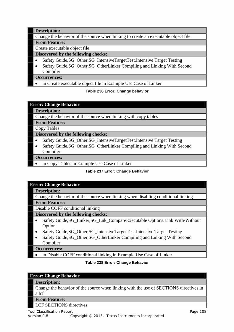
Tool Classification Report Page 108 Version 0.8 Copyright @ 2013. Texas Instruments Incorporated
Description:
Change the behavior of the source when linking to create an executable object file
From Feature:
Create executable object file
Discovered by the following checks:
Safety Guide,SG_Other,SG_IntensiveTargetTest.Intensive Target Testing
Safety Guide,SG_Other,SG_OtherLinker.Compiling and Linking With Second
Compiler
Occurrences:
in Create executable object file in Example Use Case of Linker
Table 236 Error: Change behavior
Error: Change Behavior
Description:
Change the behavior of the source when linking with copy tables
From Feature:
Copy Tables
Discovered by the following checks:
Safety Guide,SG_Other,SG_IntensiveTargetTest.Intensive Target Testing
Safety Guide,SG_Other,SG_OtherLinker.Compiling and Linking With Second
Compiler
Occurrences:
in Copy Tables in Example Use Case of Linker
Table 237 Error: Change Behavior
Error: Change Behavior
Description:
Change the behavior of the source when linking when disabling conditional linking
From Feature:
Disable COFF conditional linking
Discovered by the following checks:
Safety Guide,SG_Linker,SG_Lnk_CompareExecutable Options.Link With/Without
Option
Safety Guide,SG_Other,SG_IntensiveTargetTest.Intensive Target Testing
Safety Guide,SG_Other,SG_OtherLinker.Compiling and Linking With Second
Compiler
Occurrences:
in Disable COFF conditional linking in Example Use Case of Linker
Table 238 Error: Change Behavior
Error: Change Behavior
Description:
Change the behavior of the source when linking with the use of SECTIONS directives in
a lcf
From Feature:
LCF SECTIONS directives
Tool Classification Report Page 109 Version 0.8 Copyright @ 2013. Texas Instruments Incorporated
Discovered by the following checks:
Safety Guide,SG_Linker,SG_Lnk_CompOutputList.Compare Linker Output Files
with Reference File List
Safety Guide,SG_Other,SG_IntensiveTargetTest.Intensive Target Testing
Occurrences:
in LCF SECTIONS directives in Example Use Case of Linker
Table 239 Error: Change Behavior
Error: Change behavior
Description:
Change the behavior of the source when linking with xml link info file
From Feature:
Generate xml link info file
Discovered by the following checks:
Safety Guide,SG_Linker,SG_Lnk_CompareExecutable Info.Link with and without
generating an xml link info file
Safety Guide,SG_Other,SG_IntensiveTargetTest.Intensive Target Testing
Safety Guide,SG_Other,SG_OtherLinker.Compiling and Linking With Second
Compiler
Occurrences:
in Generate xml link info file in Example Use Case of Linker
Table 240 Error: Change behavior
Error: Change Behavior
Description:
Change the behavior of the source when linking with linker preprocessing
From Feature:
Linker preprocessing
Discovered by the following checks:
Safety Guide,SG_Other,SG_IntensiveTargetTest.Intensive Target Testing
Safety Guide,SG_Other,SG_OtherLinker.Compiling and Linking With Second
Compiler
Occurrences:
in Linker preprocessing in Example Use Case of Linker
Table 241 Error: Change Behavior
Error: Change behavior
Description:
Change the behavior of the source when linking with rom or ram model
From Feature:
Control variable initialization
Discovered by the following checks:
Safety Guide,SG_Other,SG_IntensiveTargetTest.Intensive Target Testing
Safety Guide,SG_Other,SG_OtherLinker.Compiling and Linking With Second
Compiler
Occurrences:
Tool Classification Report Page 110 Version 0.8 Copyright @ 2013. Texas Instruments Incorporated
in Control variable initialization in Example Use Case of Linker
Table 242 Error: Change behavior
Error: Change Behavior
Description:
Change the behavior of the source when linking and controlling symbol linkage
From Feature:
Control symbol linkage
Discovered by the following checks:
Safety Guide,SG_Other,SG_IntensiveTargetTest.Intensive Target Testing
Safety Guide,SG_Other,SG_OtherLinker.Compiling and Linking With Second
Compiler
Occurrences:
in Control symbol linkage in Example Use Case of Linker
Table 243 Error: Change Behavior
Error: Change Behavior
Description:
Change the behavior of the source when linking with filling holes in a lcf
From Feature:
LCF creating and filling holes
Discovered by the following checks:
Safety Guide,SG_Other,SG_IntensiveTargetTest.Intensive Target Testing
Safety Guide,SG_Other,SG_OtherLinker.Compiling and Linking With Second
Compiler
Occurrences:
in LCF creating and filling holes in Example Use Case of Linker
Table 244 Error: Change Behavior
Error: Change Behavior
Description:
Change the behavior of the source when linking with preferred function ordering
From Feature:
Preferred function ordering
Discovered by the following checks:
Safety Guide,SG_Other,SG_IntensiveTargetTest.Intensive Target Testing
Safety Guide,SG_Other,SG_OtherLinker.Compiling and Linking With Second
Compiler
Occurrences:
in Preferred function ordering in Example Use Case of Linker
Table 245 Error: Change Behavior
Error: Change Behavior
Description:
Change the behavior of the source when linking with controlled diagnostics

Tool Classification Report Page 111 Version 0.8 Copyright @ 2013. Texas Instruments Incorporated
From Feature:
Control linker diagnostics
Discovered by the following checks:
Safety Guide,SG_Linker,SG_Lnk_CompareExecutable Options.Link With/Without
Option
Safety Guide,SG_Other,SG_IntensiveTargetTest.Intensive Target Testing
Safety Guide,SG_Other,SG_OtherLinker.Compiling and Linking With Second
Compiler
Occurrences:
in Control linker diagnostics in Example Use Case of Linker
Table 246 Error: Change Behavior
Error: Change Behavior
Description:
Change the behavior of the source when linking with the use of MEMORY directives in
a lcf
From Feature:
LCF MEMORY directives
Discovered by the following checks:
Safety Guide,SG_Other,SG_IntensiveTargetTest.Intensive Target Testing
Safety Guide,SG_Other,SG_OtherLinker.Compiling and Linking With Second
Compiler
Occurrences:
in LCF MEMORY directives in Example Use Case of Linker
Table 247 Error: Change Behavior
Error: Change Behavior
Description:
Change the behavior of the source when linking with CRC tables
From Feature:
CRC tables
Discovered by the following checks:
Safety Guide,SG_Other,SG_IntensiveTargetTest.Intensive Target Testing
Safety Guide,SG_Other,SG_OtherLinker.Compiling and Linking With Second
Compiler
Occurrences:
in CRC tables in Example Use Case of Linker
Table 248 Error: Change Behavior
Error: Change behavior
Description:
Change the behavior of the source when linking with mapfile
From Feature:
Generate map file
Discovered by the following checks:
Safety Guide,SG_Linker,SG_Lnk_CompareExecutable Map.Link with and without

Tool Classification Report Page 112 Version 0.8 Copyright @ 2013. Texas Instruments Incorporated
generating a map file
Safety Guide,SG_Other,SG_IntensiveTargetTest.Intensive Target Testing
Safety Guide,SG_Other,SG_OtherLinker.Compiling and Linking With Second
Compiler
Occurrences:
in Generate map file in Example Use Case of Linker
Table 249 Error: Change behavior
Error: Copy Tables Defect
Description:
Linker does not generate copy tables
From Feature:
Copy Tables
Discovered by the following checks:
Safety Guide,SG_Linker,SG_Lnk_ReviewDissaembler.Review with Disassembler
Safety Guide,SG_TBD.To Be Defined By User
Occurrences:
in Copy Tables in Example Use Case of Linker
Table 250 Error: Copy Tables Defect
Error: Copy Tables Ignored
Description:
Linker does not generate copy tables
From Feature:
Copy Tables
Discovered by the following checks:
Safety Guide,SG_Linker,SG_Lnk_ReviewDissaembler.Review with Disassembler
Safety Guide,SG_TBD.To Be Defined By User
Occurrences:
in Copy Tables in Example Use Case of Linker
Table 251 Error: Copy Tables Ignored
Error: Hole Filling Defect
Description:
Linker fills holes incorrectly
From Feature:
LCF creating and filling holes
Occurrences:
in LCF creating and filling holes in Example Use Case of Linker
Table 252 Error: Hole Filling Defect
Error: Ignore Hole Filling
Description:
Linker does not fill holes
From Feature:
Tool Classification Report Page 113 Version 0.8 Copyright @ 2013. Texas Instruments Incorporated
LCF creating and filling holes
Discovered by the following checks:
Safety Guide,SG_Linker,SG_Lnk_ReviewMapfileSimple.Review Mapfile
Occurrences:
in LCF creating and filling holes in Example Use Case of Linker
Table 253 Error: Ignore Hole Filling
Error: Ignore MEMORY Directive
Description:
Linker ignores MEMORY directives in a lcf
From Feature:
LCF MEMORY directives
Occurrences:
in LCF MEMORY directives in Example Use Case of Linker
Table 254 Error: Ignore MEMORY Directive
Error: Ignore SECTION Directive
Description:
Linker ignores SECTIONS directives in a lcf
From Feature:
LCF SECTIONS directives
Discovered by the following checks:
Safety Guide,SG_Linker,SG_Lnk_ReviewMapfileSimple.Review Mapfile
Occurrences:
in LCF SECTIONS directives in Example Use Case of Linker
Table 255 Error: Ignore SECTION Directive
Error: Ignore UNION and GROUP
Description:
Linker ignores UNION and GROUP statements in a lcf
From Feature:
LCF UNION and GROUP statements
Discovered by the following checks:
Safety Guide,SG_Linker,SG_Lnk_ReviewMapfileSimple.Review Mapfile
Occurrences:
in LCF UNION and GROUP statements in Example Use Case of Linker
Table 256 Error: Ignore UNION and GROUP
Error: Igonre Assignment
Description:
Linker does not assign any symbols from the lcf
From Feature:
LCF assignment of symbols
Discovered by the following checks:
Safety Guide,SG_Linker,SG_Lnk_ReviewMapfileSimple.Review Mapfile
Tool Classification Report Page 114 Version 0.8 Copyright @ 2013. Texas Instruments Incorporated
Occurrences:
in LCF assignment of symbols in Example Use Case of Linker
Table 257 Error: Igonre Assignment
Error: Incorrect CRC
Description:
Linker generates incorrect CRC tables
From Feature:
CRC tables
Discovered by the following checks:
Safety Guide,SG_Linker,SG_Lnk_ReviewDissaembler.Review with Disassembler
Safety Guide,SG_TBD.To Be Defined By User
Occurrences:
in CRC tables in Example Use Case of Linker
Table 258 Error: Incorrect CRC
Error: Incorrect Objects Used
Description:
Linker does not use correct object files
From Feature:
BE-8 and BE-32 object file support
Discovered by the following checks:
Safety Guide,SG_Linker,SG_Lnk_ReviewMapfileSimple.Review Mapfile
Safety Guide,SG_Other,SG_GeneralTargetTest.General Testrun
Occurrences:
in BE-8 and BE-32 object file support in Example Use Case of Linker
Table 259 Error: Incorrect Objects Used
Error: Input file not used
Description:
Linker does not use any library input files
From Feature:
Support library input files
Discovered by the following checks:
Safety Guide,SG_Other,SG_GeneralTargetTest.General Testrun
Occurrences:
in Support library input files in Example Use Case of Linker
Table 260 Error: Input file not used
Error: MEMORY Directive Defect
Description:
Linker processes MEMORY directives incorrectly
From Feature:
LCF MEMORY directives
Discovered by the following checks:

Tool Classification Report Page 115 Version 0.8 Copyright @ 2013. Texas Instruments Incorporated
Safety Guide,SG_Linker,SG_Lnk_ReviewMapfileSimple.Review Mapfile
Occurrences:
in LCF MEMORY directives in Example Use Case of Linker
Table 261 Error: MEMORY Directive Defect
Error: No CRC
Description:
Linker does not generate CRC tables
From Feature:
CRC tables
Discovered by the following checks:
Safety Guide,SG_Linker,SG_Lnk_ReviewDissaembler.Review with Disassembler
Safety Guide,SG_TBD.To Be Defined By User
Occurrences:
in CRC tables in Example Use Case of Linker
Table 262 Error: No CRC
Error: No Diagnostics
Description:
Linker does not perform any controlled diagnostics
From Feature:
Control linker diagnostics
Discovered by the following checks:
Safety Guide,SG_Linker,Lnk_ReviewLogs.Log Review
Occurrences:
in Control linker diagnostics in Example Use Case of Linker
Table 263 Error: No Diagnostics
Error: No Disabling
Description:
Linker does not disable conditional linking
From Feature:
Disable COFF conditional linking
Discovered by the following checks:
Safety Guide,SG_Linker,SG_Lnk_ReviewDissaembler.Review with Disassembler
Occurrences:
in Disable COFF conditional linking in Example Use Case of Linker
Table 264 Error: No Disabling
Error: No Entry Point
Description:
Linker does not set the entry point
From Feature:
Set executable entry point
Discovered by the following checks:
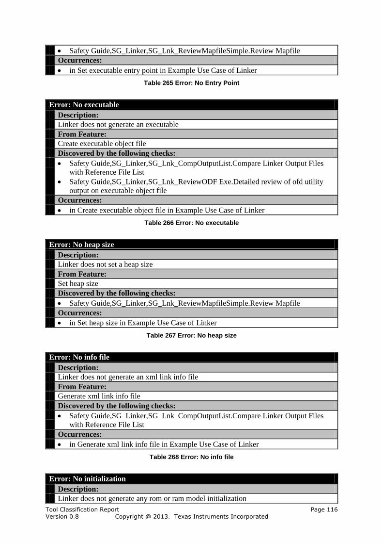
Tool Classification Report Page 116 Version 0.8 Copyright @ 2013. Texas Instruments Incorporated
Safety Guide,SG_Linker,SG_Lnk_ReviewMapfileSimple.Review Mapfile
Occurrences:
in Set executable entry point in Example Use Case of Linker
Table 265 Error: No Entry Point
Error: No executable
Description:
Linker does not generate an executable
From Feature:
Create executable object file
Discovered by the following checks:
Safety Guide,SG_Linker,SG_Lnk_CompOutputList.Compare Linker Output Files
with Reference File List
Safety Guide,SG_Linker,SG_Lnk_ReviewODF Exe.Detailed review of ofd utility
output on executable object file
Occurrences:
in Create executable object file in Example Use Case of Linker
Table 266 Error: No executable
Error: No heap size
Description:
Linker does not set a heap size
From Feature:
Set heap size
Discovered by the following checks:
Safety Guide,SG_Linker,SG_Lnk_ReviewMapfileSimple.Review Mapfile
Occurrences:
in Set heap size in Example Use Case of Linker
Table 267 Error: No heap size
Error: No info file
Description:
Linker does not generate an xml link info file
From Feature:
Generate xml link info file
Discovered by the following checks:
Safety Guide,SG_Linker,SG_Lnk_CompOutputList.Compare Linker Output Files
with Reference File List
Occurrences:
in Generate xml link info file in Example Use Case of Linker
Table 268 Error: No info file
Error: No initialization
Description:
Linker does not generate any rom or ram model initialization
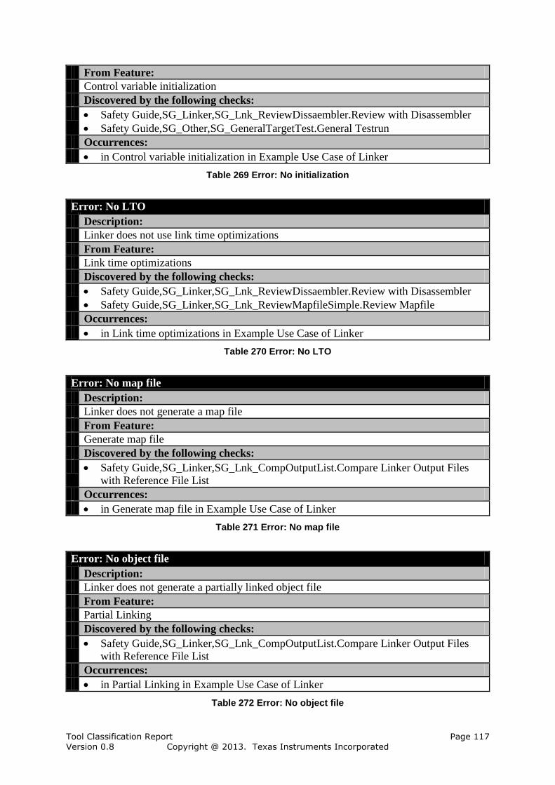
Tool Classification Report Page 117 Version 0.8 Copyright @ 2013. Texas Instruments Incorporated
From Feature:
Control variable initialization
Discovered by the following checks:
Safety Guide,SG_Linker,SG_Lnk_ReviewDissaembler.Review with Disassembler
Safety Guide,SG_Other,SG_GeneralTargetTest.General Testrun
Occurrences:
in Control variable initialization in Example Use Case of Linker
Table 269 Error: No initialization
Error: No LTO
Description:
Linker does not use link time optimizations
From Feature:
Link time optimizations
Discovered by the following checks:
Safety Guide,SG_Linker,SG_Lnk_ReviewDissaembler.Review with Disassembler
Safety Guide,SG_Linker,SG_Lnk_ReviewMapfileSimple.Review Mapfile
Occurrences:
in Link time optimizations in Example Use Case of Linker
Table 270 Error: No LTO
Error: No map file
Description:
Linker does not generate a map file
From Feature:
Generate map file
Discovered by the following checks:
Safety Guide,SG_Linker,SG_Lnk_CompOutputList.Compare Linker Output Files
with Reference File List
Occurrences:
in Generate map file in Example Use Case of Linker
Table 271 Error: No map file
Error: No object file
Description:
Linker does not generate a partially linked object file
From Feature:
Partial Linking
Discovered by the following checks:
Safety Guide,SG_Linker,SG_Lnk_CompOutputList.Compare Linker Output Files
with Reference File List
Occurrences:
in Partial Linking in Example Use Case of Linker
Table 272 Error: No object file

Tool Classification Report Page 118 Version 0.8 Copyright @ 2013. Texas Instruments Incorporated
Error: No Output
Description:
No output generated from linker when setting entry point
From Feature:
Set executable entry point
Discovered by the following checks:
Safety Guide,SG_Linker,SG_Lnk_CompOutputList.Compare Linker Output Files
with Reference File List
Occurrences:
in Set executable entry point in Example Use Case of Linker
Table 273 Error: No Output
Error: No output
Description:
No output generated from linker when setting a stack size
From Feature:
Set stack size
Discovered by the following checks:
Safety Guide,SG_Linker,SG_Lnk_CompOutputList.Compare Linker Output Files
with Reference File List
Occurrences:
in Set stack size in Example Use Case of Linker
Table 274 Error: No output
Error: No Output
Description:
No output generated from linker when using lcf assigned symbols
From Feature:
LCF assignment of symbols
Discovered by the following checks:
Safety Guide,SG_Linker,SG_Lnk_CompOutputList.Compare Linker Output Files
with Reference File List
Occurrences:
in LCF assignment of symbols in Example Use Case of Linker
Table 275 Error: No Output
Error: No output
Description:
No output generated from linker when setting a heap size
From Feature:
Set heap size
Discovered by the following checks:
Safety Guide,SG_Linker,SG_Lnk_CompOutputList.Compare Linker Output Files
with Reference File List
Occurrences:

Tool Classification Report Page 119 Version 0.8 Copyright @ 2013. Texas Instruments Incorporated
in Set heap size in Example Use Case of Linker
Table 276 Error: No output
Error: No output
Description:
No output generated from linker when using library input files
From Feature:
Support library input files
Discovered by the following checks:
Safety Guide,SG_Linker,SG_Lnk_CompOutputList.Compare Linker Output Files
with Reference File List
Occurrences:
in Support library input files in Example Use Case of Linker
Table 277 Error: No output
Error: No Output
Description:
No output generated from linker when using be-8 or be-32 object file
From Feature:
BE-8 and BE-32 object file support
Discovered by the following checks:
Safety Guide,SG_Linker,SG_Lnk_CompOutputList.Compare Linker Output Files
with Reference File List
Occurrences:
in BE-8 and BE-32 object file support in Example Use Case of Linker
Table 278 Error: No Output
Error: No Output
Description:
No output generated from linker when using link time optimizations
From Feature:
Link time optimizations
Discovered by the following checks:
Safety Guide,SG_Linker,SG_Lnk_CompOutputList.Compare Linker Output Files
with Reference File List
Occurrences:
in Link time optimizations in Example Use Case of Linker
Table 279 Error: No Output
Error: No Output
Description:
No output generated from linker when using UNION and GROUP statements in a lcf
From Feature:
LCF UNION and GROUP statements
Discovered by the following checks:

Tool Classification Report Page 120 Version 0.8 Copyright @ 2013. Texas Instruments Incorporated
Safety Guide,SG_Linker,SG_Lnk_CompOutputList.Compare Linker Output Files
with Reference File List
Occurrences:
in LCF UNION and GROUP statements in Example Use Case of Linker
Table 280 Error: No Output
Error: No output
Description:
No output generated from linker when adding to library search paths
From Feature:
Add to library search path
Discovered by the following checks:
Safety Guide,SG_Linker,SG_Lnk_CompOutputList.Compare Linker Output Files
with Reference File List
Occurrences:
in Add to library search path in Example Use Case of Linker
Table 281 Error: No output
Error: No Output
Description:
No output generated from linker when generating copy tables
From Feature:
Copy Tables
Discovered by the following checks:
Safety Guide,SG_Linker,SG_Lnk_CompOutputList.Compare Linker Output Files
with Reference File List
Occurrences:
in Copy Tables in Example Use Case of Linker
Table 282 Error: No Output
Error: No Output
Description:
No output generated from linker when disabling conditional linking
From Feature:
Disable COFF conditional linking
Discovered by the following checks:
Safety Guide,SG_Linker,SG_Lnk_CompOutputList.Compare Linker Output Files
with Reference File List
Occurrences:
in Disable COFF conditional linking in Example Use Case of Linker
Table 283 Error: No Output
Error: No Output
Description:
No output generated from linker when using SECTIONS directives in a lcf

Tool Classification Report Page 121 Version 0.8 Copyright @ 2013. Texas Instruments Incorporated
From Feature:
LCF SECTIONS directives
Discovered by the following checks:
Safety Guide,SG_Linker,SG_Lnk_CompOutputList.Compare Linker Output Files
with Reference File List
Occurrences:
in LCF SECTIONS directives in Example Use Case of Linker
Table 284 Error: No Output
Error: No output
Description:
No output generated from linker when generating xml link info file
From Feature:
Generate xml link info file
Discovered by the following checks:
Safety Guide,SG_Linker,SG_Lnk_CompOutputList.Compare Linker Output Files
with Reference File List
Occurrences:
in Generate xml link info file in Example Use Case of Linker
Table 285 Error: No output
Error: No Output
Description:
No output generated from linker when using linker preprocessing
From Feature:
Linker preprocessing
Discovered by the following checks:
Safety Guide,SG_Linker,SG_Lnk_CompOutputList.Compare Linker Output Files
with Reference File List
Occurrences:
in Linker preprocessing in Example Use Case of Linker
Table 286 Error: No Output
Error: No output
Description:
No output generated from linker when using rom or ram model
From Feature:
Control variable initialization
Discovered by the following checks:
Safety Guide,SG_Linker,SG_Lnk_CompOutputList.Compare Linker Output Files
with Reference File List
Occurrences:
in Control variable initialization in Example Use Case of Linker
Table 287 Error: No output
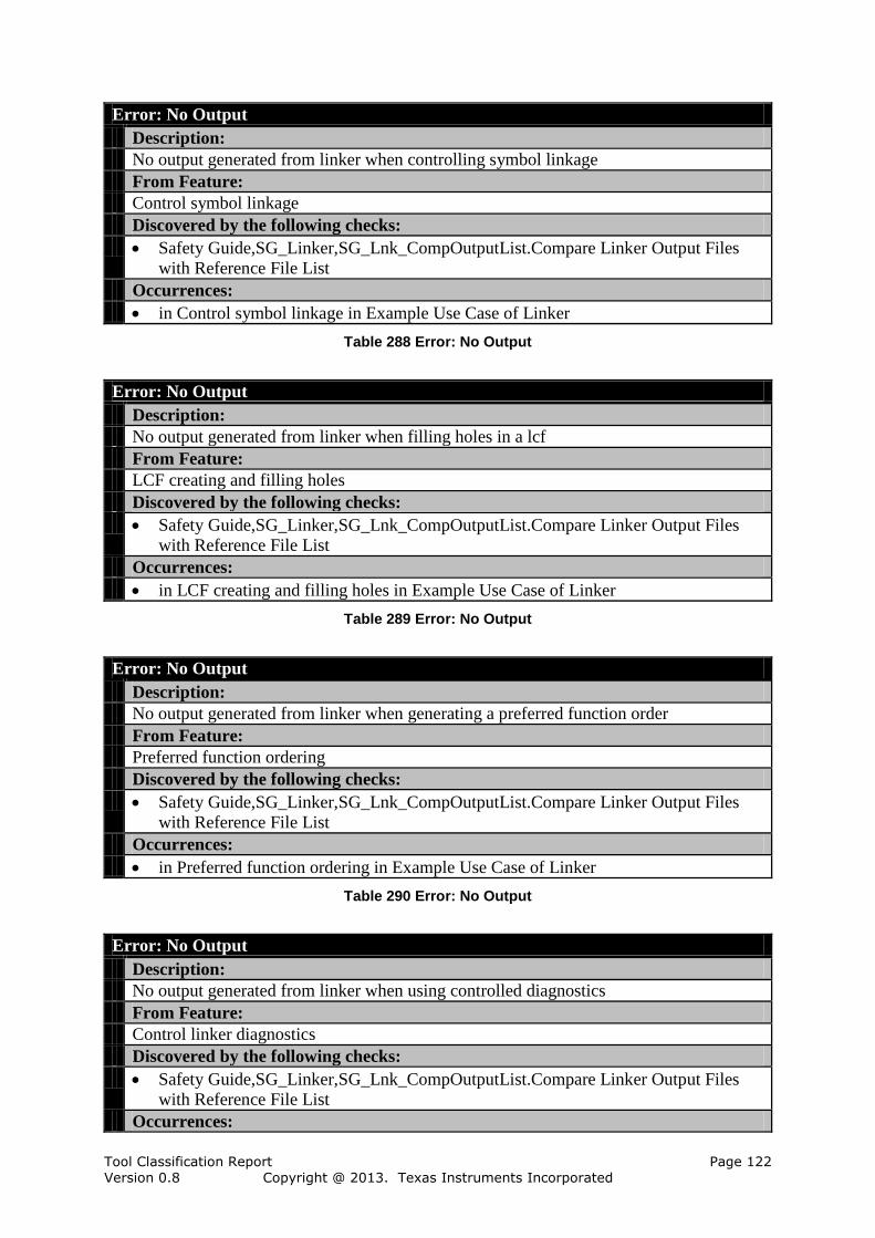
Tool Classification Report Page 122 Version 0.8 Copyright @ 2013. Texas Instruments Incorporated
Error: No Output
Description:
No output generated from linker when controlling symbol linkage
From Feature:
Control symbol linkage
Discovered by the following checks:
Safety Guide,SG_Linker,SG_Lnk_CompOutputList.Compare Linker Output Files
with Reference File List
Occurrences:
in Control symbol linkage in Example Use Case of Linker
Table 288 Error: No Output
Error: No Output
Description:
No output generated from linker when filling holes in a lcf
From Feature:
LCF creating and filling holes
Discovered by the following checks:
Safety Guide,SG_Linker,SG_Lnk_CompOutputList.Compare Linker Output Files
with Reference File List
Occurrences:
in LCF creating and filling holes in Example Use Case of Linker
Table 289 Error: No Output
Error: No Output
Description:
No output generated from linker when generating a preferred function order
From Feature:
Preferred function ordering
Discovered by the following checks:
Safety Guide,SG_Linker,SG_Lnk_CompOutputList.Compare Linker Output Files
with Reference File List
Occurrences:
in Preferred function ordering in Example Use Case of Linker
Table 290 Error: No Output
Error: No Output
Description:
No output generated from linker when using controlled diagnostics
From Feature:
Control linker diagnostics
Discovered by the following checks:
Safety Guide,SG_Linker,SG_Lnk_CompOutputList.Compare Linker Output Files
with Reference File List
Occurrences:

Tool Classification Report Page 123 Version 0.8 Copyright @ 2013. Texas Instruments Incorporated
in Control linker diagnostics in Example Use Case of Linker
Table 291 Error: No Output
Error: No Output
Description:
No output generated from linker when using MEMORY directives in a lcf
From Feature:
LCF MEMORY directives
Discovered by the following checks:
Safety Guide,SG_Linker,SG_Lnk_CompOutputList.Compare Linker Output Files
with Reference File List
Occurrences:
in LCF MEMORY directives in Example Use Case of Linker
Table 292 Error: No Output
Error: No Output
Description:
No output generated from linker when generating CRC tables
From Feature:
CRC tables
Discovered by the following checks:
Safety Guide,SG_TBD.To Be Defined By User
Occurrences:
in CRC tables in Example Use Case of Linker
Table 293 Error: No Output
Error: No output
Description:
No output generated from linker when generating map file
From Feature:
Generate map file
Discovered by the following checks:
Safety Guide,SG_Linker,SG_Lnk_CompOutputList.Compare Linker Output Files
with Reference File List
Occurrences:
in Generate map file in Example Use Case of Linker
Table 294 Error: No output
Error: No output file name
Description:
Linker does not generate output file with specific name
From Feature:
Set output file name
Discovered by the following checks:
Safety Guide,SG_Linker,SG_Lnk_CompOutputList.Compare Linker Output Files
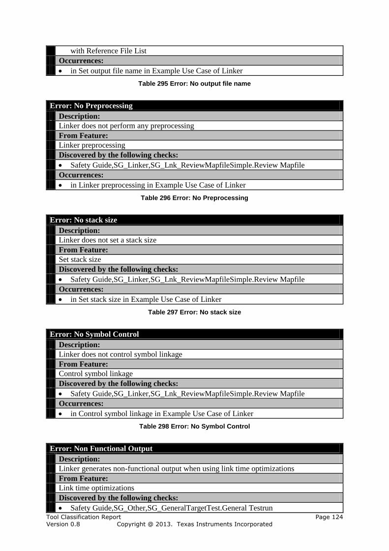
Tool Classification Report Page 124 Version 0.8 Copyright @ 2013. Texas Instruments Incorporated
with Reference File List
Occurrences:
in Set output file name in Example Use Case of Linker
Table 295 Error: No output file name
Error: No Preprocessing
Description:
Linker does not perform any preprocessing
From Feature:
Linker preprocessing
Discovered by the following checks:
Safety Guide,SG_Linker,SG_Lnk_ReviewMapfileSimple.Review Mapfile
Occurrences:
in Linker preprocessing in Example Use Case of Linker
Table 296 Error: No Preprocessing
Error: No stack size
Description:
Linker does not set a stack size
From Feature:
Set stack size
Discovered by the following checks:
Safety Guide,SG_Linker,SG_Lnk_ReviewMapfileSimple.Review Mapfile
Occurrences:
in Set stack size in Example Use Case of Linker
Table 297 Error: No stack size
Error: No Symbol Control
Description:
Linker does not control symbol linkage
From Feature:
Control symbol linkage
Discovered by the following checks:
Safety Guide,SG_Linker,SG_Lnk_ReviewMapfileSimple.Review Mapfile
Occurrences:
in Control symbol linkage in Example Use Case of Linker
Table 298 Error: No Symbol Control
Error: Non Functional Output
Description:
Linker generates non-functional output when using link time optimizations
From Feature:
Link time optimizations
Discovered by the following checks:
Safety Guide,SG_Other,SG_GeneralTargetTest.General Testrun

Tool Classification Report Page 125 Version 0.8 Copyright @ 2013. Texas Instruments Incorporated
Occurrences:
in Link time optimizations in Example Use Case of Linker
Table 299 Error: Non Functional Output
Error: Ordering Defect
Description:
Linker generates incorrect function orderong
From Feature:
Preferred function ordering
Discovered by the following checks:
Safety Guide,SG_Linker,SG_Lnk_ReviewDissaembler.Review with Disassembler
Safety Guide,SG_TBD.To Be Defined By User
Occurrences:
in Preferred function ordering in Example Use Case of Linker
Table 300 Error: Ordering Defect
Error: Paths not used
Description:
Linker does not use any library search paths
From Feature:
Add to library search path
Discovered by the following checks:
Safety Guide,SG_Other,SG_GeneralTargetTest.General Testrun
Occurrences:
in Add to library search path in Example Use Case of Linker
Table 301 Error: Paths not used
Error: SECTION Directive Defect
Description:
Linker processes SECTIONS directives incorrectly
From Feature:
LCF SECTIONS directives
Discovered by the following checks:
Safety Guide,SG_Linker,SG_Lnk_ReviewMapfileSimple.Review Mapfile
Occurrences:
in LCF SECTIONS directives in Example Use Case of Linker
Table 302 Error: SECTION Directive Defect
Error: UNION and GROUP Defect
Description:
Linker processes UNION and GROUP statements incorrectly
From Feature:
LCF UNION and GROUP statements
Discovered by the following checks:
Safety Guide,SG_Linker,SG_Lnk_ReviewMapfileSimple.Review Mapfile
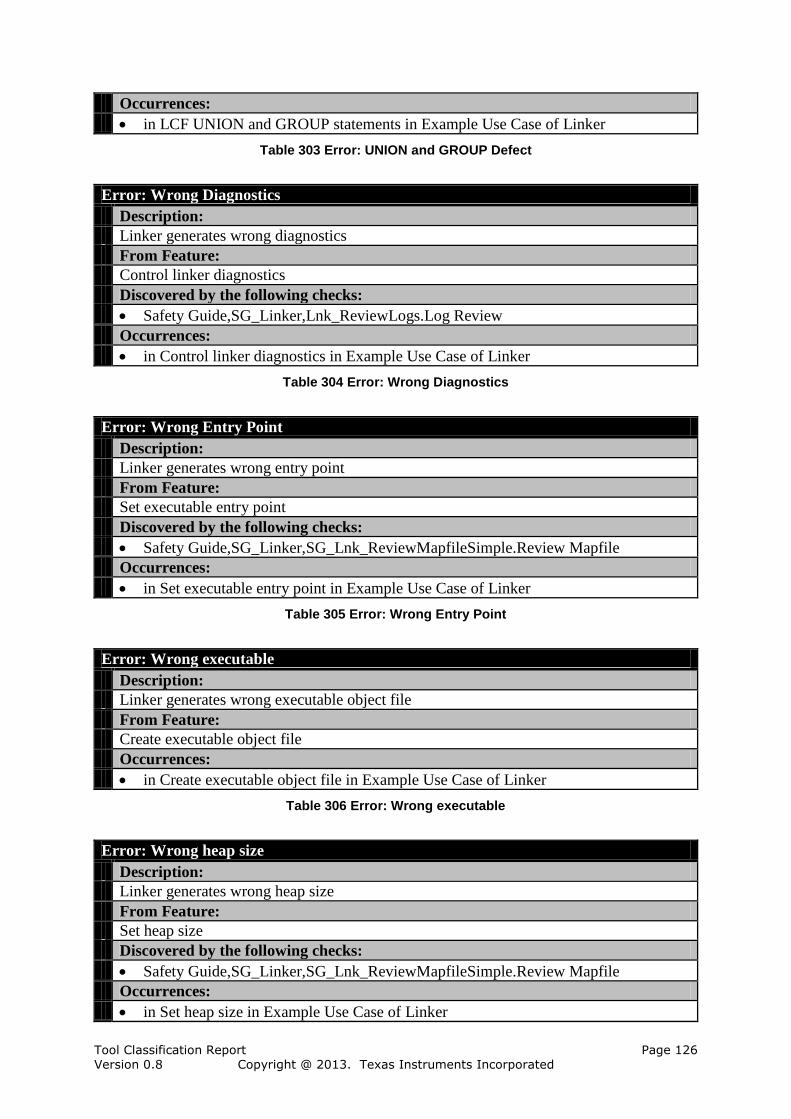
Tool Classification Report Page 126 Version 0.8 Copyright @ 2013. Texas Instruments Incorporated
Occurrences:
in LCF UNION and GROUP statements in Example Use Case of Linker
Table 303 Error: UNION and GROUP Defect
Error: Wrong Diagnostics
Description:
Linker generates wrong diagnostics
From Feature:
Control linker diagnostics
Discovered by the following checks:
Safety Guide,SG_Linker,Lnk_ReviewLogs.Log Review
Occurrences:
in Control linker diagnostics in Example Use Case of Linker
Table 304 Error: Wrong Diagnostics
Error: Wrong Entry Point
Description:
Linker generates wrong entry point
From Feature:
Set executable entry point
Discovered by the following checks:
Safety Guide,SG_Linker,SG_Lnk_ReviewMapfileSimple.Review Mapfile
Occurrences:
in Set executable entry point in Example Use Case of Linker
Table 305 Error: Wrong Entry Point
Error: Wrong executable
Description:
Linker generates wrong executable object file
From Feature:
Create executable object file
Occurrences:
in Create executable object file in Example Use Case of Linker
Table 306 Error: Wrong executable
Error: Wrong heap size
Description:
Linker generates wrong heap size
From Feature:
Set heap size
Discovered by the following checks:
Safety Guide,SG_Linker,SG_Lnk_ReviewMapfileSimple.Review Mapfile
Occurrences:
in Set heap size in Example Use Case of Linker
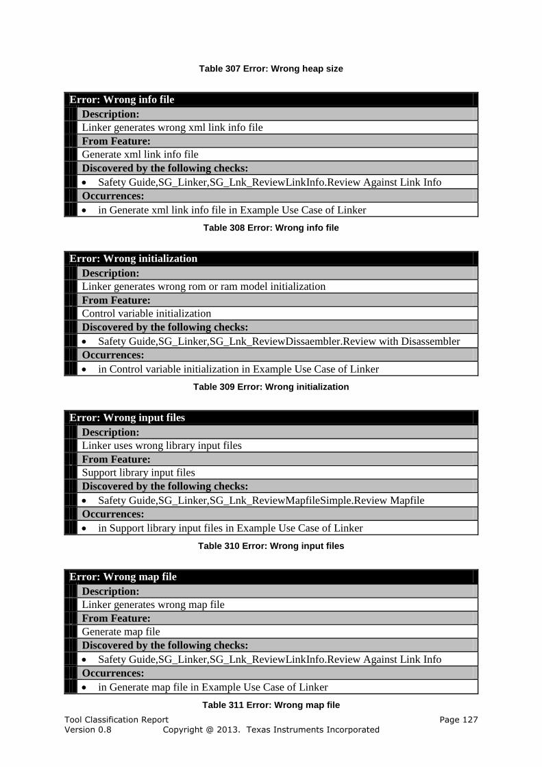
Tool Classification Report Page 127 Version 0.8 Copyright @ 2013. Texas Instruments Incorporated
Table 307 Error: Wrong heap size
Error: Wrong info file
Description:
Linker generates wrong xml link info file
From Feature:
Generate xml link info file
Discovered by the following checks:
Safety Guide,SG_Linker,SG_Lnk_ReviewLinkInfo.Review Against Link Info
Occurrences:
in Generate xml link info file in Example Use Case of Linker
Table 308 Error: Wrong info file
Error: Wrong initialization
Description:
Linker generates wrong rom or ram model initialization
From Feature:
Control variable initialization
Discovered by the following checks:
Safety Guide,SG_Linker,SG_Lnk_ReviewDissaembler.Review with Disassembler
Occurrences:
in Control variable initialization in Example Use Case of Linker
Table 309 Error: Wrong initialization
Error: Wrong input files
Description:
Linker uses wrong library input files
From Feature:
Support library input files
Discovered by the following checks:
Safety Guide,SG_Linker,SG_Lnk_ReviewMapfileSimple.Review Mapfile
Occurrences:
in Support library input files in Example Use Case of Linker
Table 310 Error: Wrong input files
Error: Wrong map file
Description:
Linker generates wrong map file
From Feature:
Generate map file
Discovered by the following checks:
Safety Guide,SG_Linker,SG_Lnk_ReviewLinkInfo.Review Against Link Info
Occurrences:
in Generate map file in Example Use Case of Linker
Table 311 Error: Wrong map file

Tool Classification Report Page 128 Version 0.8 Copyright @ 2013. Texas Instruments Incorporated
Error: Wrong object file
Description:
Linker generates wrong partially linked object file
From Feature:
Partial Linking
Discovered by the following checks:
Safety Guide,SG_Linker,SG_Lnk_ReviewMapfileComplex.Review Mapfile
Safety Guide,SG_Linker,SG_Lnk_ReviewODF Obj.Detailed review of ofd utility
output on partially linked object file
Occurrences:
in Partial Linking in Example Use Case of Linker
Table 312 Error: Wrong object file
Error: Wrong output file name
Description:
Linker generates wrong output file name
From Feature:
Set output file name
Discovered by the following checks:
Safety Guide,SG_Linker,SG_Lnk_CompOutputList.Compare Linker Output Files
with Reference File List
Occurrences:
in Set output file name in Example Use Case of Linker
Table 313 Error: Wrong output file name
Error: Wrong paths
Description:
Linker uses wrong library search paths
From Feature:
Add to library search path
Discovered by the following checks:
Safety Guide,SG_Linker,SG_Lnk_ReviewMapfileSimple.Review Mapfile
Occurrences:
in Add to library search path in Example Use Case of Linker
Table 314 Error: Wrong paths
Error: Wrong Preprocessing
Description:
Linker uses wrong preprocessin
From Feature:
Linker preprocessing
Discovered by the following checks:
Safety Guide,SG_Linker,SG_Lnk_ReviewMapfileSimple.Review Mapfile
Occurrences:

Tool Classification Report Page 129 Version 0.8 Copyright @ 2013. Texas Instruments Incorporated
in Linker preprocessing in Example Use Case of Linker
Table 315 Error: Wrong Preprocessing
Error: Wrong stack size
Description:
Linker generates wrong stack size
From Feature:
Set stack size
Discovered by the following checks:
Safety Guide,SG_Linker,SG_Lnk_ReviewMapfileSimple.Review Mapfile
Occurrences:
in Set stack size in Example Use Case of Linker
Table 316 Error: Wrong stack size
Error: Wrong Symbol Control
Description:
Linker generates wrong symbol linkage
From Feature:
Control symbol linkage
Discovered by the following checks:
Safety Guide,SG_Linker,SG_Lnk_ReviewMapfileSimple.Review Mapfile
Occurrences:
in Control symbol linkage in Example Use Case of Linker
Table 317 Error: Wrong Symbol Control
6.7 Additional Information
This section contains additional information from the formal model of the tool chain.
Additional information is not required from the ISO 26262 for the determination of the TCL,
but eases the modeling process and the understanding of the error flow.
6.7.1 Artifacts
The analysis incorporates artifacts for the validation of the model. If an error is checked by
another tool, then there should be information flow between them. Artifacts can be used to
model this flow and our analysis checks if there is an information flow between error sources
and error sinks.
The tool chain "TI Compiler Tools" is using 14 artifacts, which are described hereafter.
Artifact: Archived Object Library
Description:
A library of object files created by the archiver
Table 318 Artifact: Archived Object Library
Artifact: Assembly files
Description:
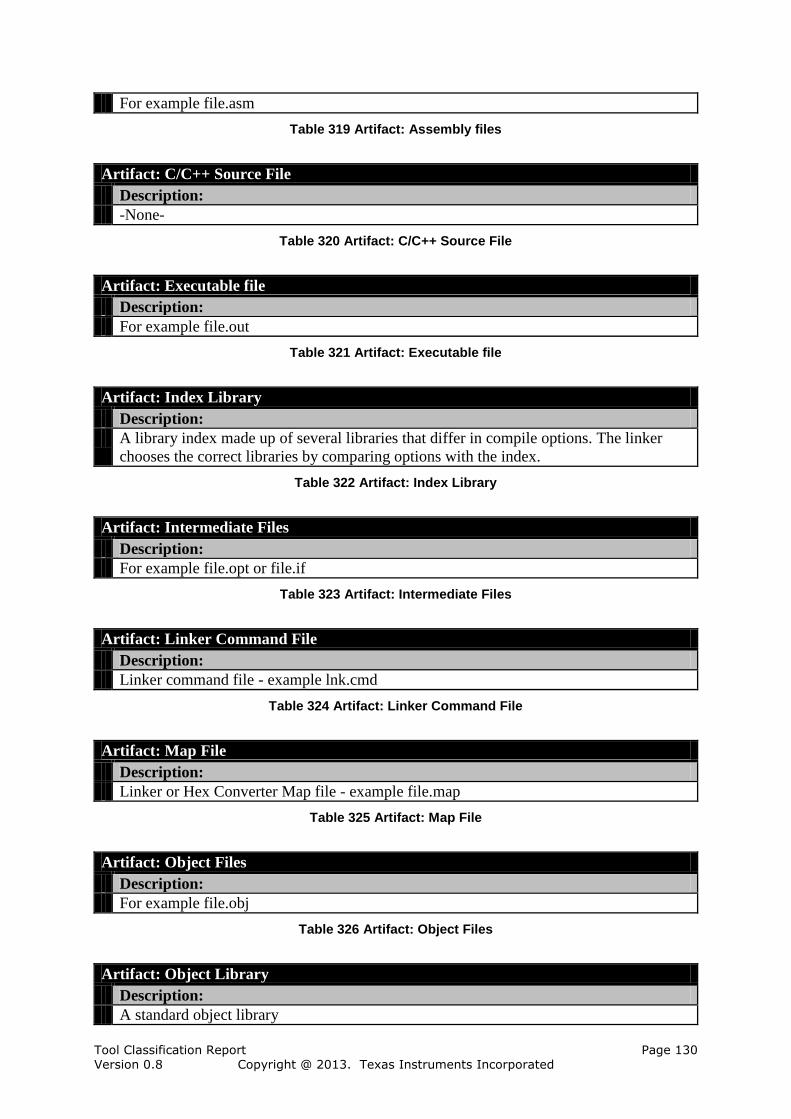
Tool Classification Report Page 130 Version 0.8 Copyright @ 2013. Texas Instruments Incorporated
For example file.asm
Table 319 Artifact: Assembly files
Artifact: C/C++ Source File
Description:
-None-
Table 320 Artifact: C/C++ Source File
Artifact: Executable file
Description:
For example file.out
Table 321 Artifact: Executable file
Artifact: Index Library
Description:
A library index made up of several libraries that differ in compile options. The linker
chooses the correct libraries by comparing options with the index.
Table 322 Artifact: Index Library
Artifact: Intermediate Files
Description:
For example file.opt or file.if
Table 323 Artifact: Intermediate Files
Artifact: Linker Command File
Description:
Linker command file - example lnk.cmd
Table 324 Artifact: Linker Command File
Artifact: Map File
Description:
Linker or Hex Converter Map file - example file.map
Table 325 Artifact: Map File
Artifact: Object Files
Description:
For example file.obj
Table 326 Artifact: Object Files
Artifact: Object Library
Description:
A standard object library

Tool Classification Report Page 131 Version 0.8 Copyright @ 2013. Texas Instruments Incorporated
Table 327 Artifact: Object Library
Artifact: Options and Commands
Description:
The options and commands for the Compiler (but not the arguments).
Table 328 Artifact: Options and Commands
Artifact: Preprocess Source File
Description:
Preprocessed source files - example file.pp
Table 329 Artifact: Preprocess Source File
Artifact: Relocatable (Partially-linked) Object file
Description:
-None-
Table 330 Artifact: Relocatable (Partially-linked) Object file
Artifact: XML Link Info File
Description:
XML link info file - example file.xml
Table 331 Artifact: XML Link Info File
6.7.2 Error Model for the TI Compiler Tools Tool Chain
The error model consists of general attributes that are mapped to the used tools or use cases.
Each of these mapped elements receives a copy of the listed errors.
In the following sections all used attributes, errors, checks and restrictions are described
6.7.2.1 Tool Attribute Descriptions
The following 3 general tool attributes have been used in the analysis of the "TI Compiler
Tools".
Tool Attribute: Compiling
Description:
-None-
Contains the following potential errors:
No Object File Generated
Wrong Object-Code Behavior
Wrong or Missing Source Files Compiled
Table 332 Tool Attribute: Compiling
Tool Attribute: File Generator
Description:
-None-
Contains the following potential errors:
No File Created

Tool Classification Report Page 132 Version 0.8 Copyright @ 2013. Texas Instruments Incorporated
Semantic Error
Syntax Error
Table 333 Tool Attribute: File Generator
Tool Attribute: Output messages to stdio
Description:
-None-
Contains the following potential errors:
Incomplete message to stdio
Table 334 Tool Attribute: Output messages to stdio
6.7.2.2 Artifact Attribute Descriptions
The following general artifact attribute has been used in the analysis of the "TI Compiler
Tools".
Artifact Attribute: XML
Description:
XML files have typical errors
Contains the following potential errors:
Contains wrong values
Syntax Errors
Wrong encoding
Table 335 Artifact Attribute: XML
6.7.2.3 Error Descriptions
The following 10 errors have been used in the analysis of the "TI Compiler Tools".
Error: Contains wrong values
Description:
Semantic erros in the xml
From artifact attribute:
XML
Table 336 Error: Contains wrong values
Error: Incomplete message to stdio
Description:
The message is not output completely to stdio.
From tool attribute:
Output messages to stdio
Table 337 Error: Incomplete message to stdio
Error: No File Created
Description:
Files, that are intented to be generated, are missing after generation (e.g. missing write
permissions)
From tool attribute:

Tool Classification Report Page 133 Version 0.8 Copyright @ 2013. Texas Instruments Incorporated
File Generator
Table 338 Error: No File Created
Error: No Object File Generated
Description:
-None-
From tool attribute:
Compiling
Table 339 Error: No Object File Generated
Error: Semantic Error
Description:
The generated file contains the wrong data or misses data
From tool attribute:
File Generator
Table 340 Error: Semantic Error
Error: Syntax Error
Description:
The generated file does not conform the expected syntax resp. format
From tool attribute:
File Generator
Table 341 Error: Syntax Error
Error: Syntax Errors
Description:
-None-
From artifact attribute:
XML
Table 342 Error: Syntax Errors
Error: Wrong encoding
Description:
-None-
From artifact attribute:
XML
Table 343 Error: Wrong encoding
Error: Wrong Object-Code Behavior
Description:
Object code does not behave as required or intended
From tool attribute:
Compiling

Tool Classification Report Page 134 Version 0.8 Copyright @ 2013. Texas Instruments Incorporated
Table 344 Error: Wrong Object-Code Behavior
Error: Wrong or Missing Source Files Compiled
Description:
-None-
From tool attribute:
Compiling
Table 345 Error: Wrong or Missing Source Files Compiled

Tool Classification Report Page 135 Version 0.8 Copyright @ 2013. Texas Instruments Incorporated
7 References
[61508] International Electrotechnical Commission, IEC 61508, Functional
safety of electrical/electronic/programmable electronic safety-related systmes, Edition 2.0, Apr 2010.
[DO178C] RTCA. DO-178C: Software Considerations in Airbone Systems and
Equipment Certification, 1st Edition 2011-12-13.
[DO330] RTCA. DO-330: Software Tool Qualification Considerations 1st Edition 2011-12-13.
[EN50128]: BS EN 50128:2011, Railway applications — Communication, signalling and processing systems — Software for railway control and protection
systems, BSI Standards Publication
[ISO26262] ISO/FDIS 26262 Road Vehicles –Functional safety–, Draft International Standard of International Organization for Standardization, BL19, 2010-12-07
[SAFECOMP12] Determining Potential Errors in Tool Chains: Strategies to Reach
Tool Confidence According to ISO 26262, SAFECOMP 2012, Wildmoser, Philipps, Slotosch
[TCA] TI C/C++ Compiler, tool available on www.validas.de/TCA.html, verwendete Version 1.8.1
[TI] Tool Impacts determination in TI C/C++ Compiler Chain
[TCA_UM] TI C/C++ Compiler, Version 1.8.1, User Manual Version, (<TCAHome>/plugins/Documentation/UserManual.pdf)
[TQP] Tool Qualification Plan for the tool(s) of TI C/C++ Compiler Chain to be constraint, generated during tool qualification
[TSM] Tool Saftey Manual for the tool(s) of TI C/C++ Compiler Chain to be
qualified, generated during tool qualification