to download the echoflex app - lighting design lab
TRANSCRIPT

To download the Echoflex App:
iTunes: https://itunes.apple.com/us/app/echoaccess/id1003870103?ls=1&mt=8
Google Play: https://play.google.com/store/apps/details?id=com.etc.echoaccessmobile

Unison Echo® EchoConnect® Station Power ETC®
1 of 8
Echo Control Series
O R D E R I N G I N F O R M A T I O N
EchoConnect Power SuppliesMODEL DESCRIPTION
E-SPS Echo Station Power Supply, Knockout Mount
E-SPS-DIN DIN Rail Mount Station Power Supply with 24V Aux
E-SPM DRd Station Power Module
E-SPM-A DRd Station Power Module with 24V Aux
E-SPM-RM Rack-Mount Station Power Module
E-SPM-RM-A Rack-Mount Station Power Module with 24V Aux
E-SPM-WM Wall-Mount Station Power Module
E-SPM-WM-A Wall-Mount Station Power Module with 24V Aux
E-APS 24V Aux Power Supply, Knockout Mount
EchoConnect Power Supply AccessoriesMODEL DESCRIPTION
E-C5T-ST Category-5 Station Wiring Kit
E-C5T-WM Category-5 Wiring Termination Box
E-C5T-RM Category-5 Wiring Termination Tray
G E N E R A L I N F O R M A T I O N
A member of ETC’s Unison® Echo family of lighting-control and power-control products, the Echo Station Power Supply provides EchoConnect power for stations, responsive controls and power controllers. Echo Station Power Supplies are designed for use with distributed Echo Control Systems, Unison DRd Power Enclosures with Echo control, Echo Relay Panels and Sensor3 Power Control Systems.
APPLICATIONS• Houses of worship • Education• Hospitality• Healthcare facilities• Office buildings• Conference rooms• Meeting rooms• Retail
FEATURES• Designed for use with any EchoConnect-enabled station,
responsive controls or Echo power controllers• EchoConnect: Two-wire, topology-free system gives you the
freedom to put stations where you need them• Multiple form factors and mounting options available• Plug and play: ready to go out of the box with no software or
programming required SYSTEM LIMITATIONS
• Up to 1640 feet (500 meters) of control wiring• DRd, Wall-, Rack- and DIN Rail Mount:
- Up to 16 stations and responsive controls - Up to 16 power controllers or panels
• Echo Station Power Supply - Up to six stations and responsive controls - Up to six power controllers or panels
GENERAL• UL and cUL LISTED• CE Marked (Except E-SPS and E-APS)
Supply

Unison Echo EchoConnect Station Power SupplyETC
2 of 8
Echo Control Series
S P E C I F I C A T I O N S
FUNCTIONAL• Provides EchoConnect power for up to 6 or16 stations or
Responsive Controls and 6 or 16 power controllers or panels• Supports 1640 feet (500 meters) of control wiring
MECHANICAL• Echo Station/Auxiliary Power Supply
- Mounts using half-inch conduit knockout - Constructed of injection-molded ABS plastic
• DRd, Wall and Rack Mount: - 18-gauge formed steel construction - Fine-texture, scratch-resistant, epoxy paint - Convection cooled - Fully contained plug-in module with no discrete wire
connections (DRd only) - Front panel status indicators - Wall-mount and 19-inch rack-mount variants available
• E-SPS-DIN - DIN Rail mounting complies with DIN43880 (35/7.5 rail)
ELECTRICAL• DRd, Wall and Rack Mount, E-SPS, E-APS:
- 100V-277V, 50/60Hz, two-wire+GND power input• E-SPS-DIN
- 100V-240V, 50/60Hz, two-wire+GND power input• Optional 24V Aux power options for connected devices • EchoConnect two-wire control network utilizing low-voltage
Class 2 wiring • Topology-free and polarity-independent wiring over Belden
8471 or equivalent and one #14 ESD drain wire• Wiring may be bus, loop, homerun or any combination
of these• Up to 1640 feet (500 meters) of control wiring per system• Supports optional Cat5 or better wiring using Belden 1583A
or equivalent - Requires optional Cat5 termination accessories
• E-SPS-DIN includes 24v power supply• UL and cUL LISTED• CE Marked (Except E-SPS and E-APS)
THERMAL • E-SPS, E-APS and E-SPS-DIN:
- Ambient room temperature: 0-50°C / 32-122°F - Ambient humidity: 5-95% non-condensing
• DRd, Wall- and Rack-Mount - Ambient room temperature: 0-40°C / 32-104°F - Ambient humidity: 10-90% non-condensing
E C H O C O N N E C T I N F O R M A T I O N
E-SPS EchoConnect Power Supply EchoConnect: Provides 6U of control power and
and 6U of Output Power
Auxiliary Power: Not provided
E-SPS-DIN EchoConnect Power Supply EchoConnect: Provides 16U of control power and
16U of Output Power
Auxiliary Power: Provides 1500mA
E-SPM EchoConnect Power Supply EchoConnect: Provides 16U of control power and
16U of Output Power
Auxiliary Power: Not Provided
E-SPM-A EchoConnect Power Supply EchoConnect: Provides 16U of control power and
16U of Output Power
Auxiliary Power: Provides 1500mA
E-SPM-RM EchoConnect Power Supply EchoConnect: Provides 16U of control power and
16U of Output Power
Auxiliary Power: Not Provided
E-SPM-RM-A EchoConnect Power Supply EchoConnect: Provides 16U of control power and
16U of Output Power
Auxiliary Power: Provides 1500mA
E-SPM-WM Power Supply EchoConnect: Provides 16U of control power and
16U of Output Power
Auxiliary Power: Not Provided
E-SPM-WM-A EchoConnect Power Supply EchoConnect: Provides 16U of control power and
16U of Output Power
Auxiliary Power: Provides 1500mA
APS Auxiliary Power Supply EchoConnect: Not Provided
Auxiliary Power: Provides 160mA

E C H O F A M I LY O F P R O D U C T S
EchoConnect Power SuppliesMODEL DESCRIPTION
E-SPS 6U Room Station Power Supply, Knockout Mount
E-SPS-DIN 16U DIN rail Station Power Supply with 24V Aux
E-SPM 16U DRd Station Power Module
E-SPM-A 16U DRd Station Power Module with 24V Aux
E-SPM-RM 16U Rack-Mount Station Power Module Aux
E-SPM-RM-A 16U Rack-Mount Station Power Module 24V Aux
E-SPM-WM 16U Wall-Mount Station Power Module
E-SPM-WM-A 16U Wall-Mount Station Power Module 24V Aux
E-APS 24V Aux Power Supply, Knockout Mount
Echo StationsMODEL DESCRIPTION
E1001 Inspire One Button Station
E1002 Inspire Two Button Station
E1004 Inspire Four Button Station
E1006 Inspire Six Button Station
E1008 Inspire Eight Button Station
E1104 Inspire Four Button with Fader Station
EPS05 Echo Preset Station - 5 Button
EPS10 Echo Preset Station - 10 Button
EPSLO Echo Lockout Station
E-ATC Echo TimeClock
Echo Responsive Controls MODEL DESCRIPTION
ELS Light Sensor
EOCC Ceiling-Mount PIR Occupancy Sensor
EVAC Ceiling-Mount PIR Vacancy Sensor
E-DOC-C Ceiling-Mount Dual Tech Occupancy Sensor
E-DVAC-C Ceiling-Mount Dual Tech Vacancy Sensor
E-DOC-W Wall-Mount Dual Tech Occupancy Sensor
E-DVAC-W Wall-Mount Dual Tech Vacancy Sensor
E-DOC-SM1 Switch-Mount Dual Tech Sensor - One Button
E-DOC-SM2 Switch-Mount Dual Tech Sensor - Two Button
Echo InterfacesMODEL DESCRIPTION
EACC EchoAccess™ Interface
EEB Echo Expansion Bridge
EDMXC Echo DMX Scene Controller
EEI Echo-Echofl ex Interface
ECII Echo Contact Input Interface
ECOI Echo Contact Output Interface
Zone ControllersMODEL DESCRIPTION
ERC One Zone Relay Controller
EDRC Two Zone Relay Controller
ELD One Zone 0-10V Dimming Controller
EDLD Two Zone 0-10V Dimming Controller
ESSC One Zone SmartSpace Controller
EDSSC Two Zone SmartSpace Controller
ELVD 600-Watt Phase Adaptive Dimmer
ELVD-277 600-Watt Phase Adaptive Dimmer- 277V
Room ControllersMODEL DESCRIPTION
ERMC4 Four Zone Room Controller
ERMCT4 Four Zone Room Controller with TimeClock
ERMC8 Eight Zone Room Controller
ERMCT8 Eight Zone Room Controller with TimeClock
Panel ProductsMODEL DESCRIPTION
ERP Echo Relay Panel Mains Feed
ERP-FT Echo Relay Panel Feed Through
SensorIQ Sensor IQ Intelligent Breaker System
SR3 Sensor3 Power Control System
DRd Unison DRd with Echo Control
Unison Echo EchoConnect Station Power SupplyETC
3 of 8
Echo Control Series

Unison Echo EchoConnect Station Power SupplyETC
4 of 8
Echo Control Series
SMALL SYSTEM
MEDIUM SYSTEM
CONFERENCE ROOM
S A M P L E E C H O S Y S T E M S

Unison Echo EchoConnect Station Power SupplyETC
5 of 8
Echo Control Series
MEDIUM BALLROOM
S A M P L E E C H O S Y S T E M S

Unison Echo EchoConnect Station Power SupplyETC
6 of 8
Echo Control Series
P H Y S I C A L
Module Dimensions*
MODEL HEIGHT WIDTH DEPTH
inches mm inches mm inches mm
E-SPM(-A) 2.6 67 12.2 310 5.9 150
E-SPM-WM(-A) 14 356 10.5 267 3.06 79
E-SPM-RM(-A) 3.46 88 19 483 10.04 255
E-SPS(-APS) 1.97 51 35 89 2.19 56
E-SPS-DIN 4.33 110 2.96 75 3.90 99
*Weights and dimensions typical
Module Weights*
MODEL WEIGHT SHIPPING WEIGHT
lbs kgs lbs kgs
E-SPM(-A) 4.8 2.18 5.8 2.63
E-SPM-WM(-A) 14.7 6.67 15.7 7.12
E-SPM-RM(-A) 15 6.80 16 7.26
E-SPS(-APS) 1 0.45 1.5 0.68
E-SPS-DIN 1 0.45 1.5 0.68
2.60”67mm
5.90”150mm
12.20”310mm
10.50”267mm 3.00”
77mm0.06”2mm8.70”
221mm
14.00”356mm
11.50”293mm(Mounting reference)
Mounting keyhole (typical)
E-SPM(-A)
E-SPM-WM(-A)

Unison Echo EchoConnect Station Power SupplyETC
7 of 8
Echo Control Series
14.00”356mm
19.00”483mm
0.23”6mm
0.12”4mm
9.33”237mm
0.71”19mm
3.00”77mm 3.46”
88mm
P H Y S I C A L
3.50”89mm
2.19”56mm
1.97”51mm
E-SPM-RM
E-SPS / E-APS

Unison Echo EchoConnect Station Power SupplyETC
Echo Control Series
P H Y S I C A L
ESPS-DIN
8 of 8
Corporate Headquarters n 3031 Pleasant View Rd, PO Box 620979, Middleton WI 53562 0979 USA n +1 608 831 4116
London, UK n Unit 26-28, Victoria Industrial Estate, Victoria Road, London W3 6UU, UK n +44 (0) 20 8896 1000
Rome, IT n Via Pieve Torina, 48, 00156 Rome, Italy n +39 (06) 32 111 683
Holzkirchen, DE n Ohmstrasse 3, 83607 Holzkirchen, Germany n +49 (80 24) 47 00-0
Hong Kong n Room 1801, 18/F, Tower 1 Phase 1, Enterprise Square, 9 Sheung Yuet Road, Kowloon Bay, Kowloon, Hong Kong n +852 2799 1220
Web n etcconnect.com n Copyright©2017 ETC. All Rights Reserved. All product information and specifications subject to change. 7186L1008 Rev K 08/17

Description 902 MHz ModelComplete Room Controller - 120/277/347 VAC ERDRC-FCU 120/277/347
Complete Room Controller - F Series
1
OverviewEchoflex’s lighting controllers use wireless technology to monitor the room’s environment. The ERDRC controller can activate lighting loads with received input from a linked sensor or switch. As a lighting controller, it operates lights based on:
• ambient light levels monitored by an wireless photo sensor
• occupancy state monitored by a wireless occupancy sensor
• occupancy state from a connected wired occupancy sensor
• switch action from a wireless wall switch• gateway control implementing scheduled events
The controller will fade lights up or down using the dimming output for a switched event. The controller can also be configured to fade lights based on an occupancy sensor ON or OFF event. With auto detection on the low voltage dimming interface, the controller can adjust between switching only to dimming automatically. A photo-inhibit feature disables Auto-ON when the natural light level measured by the light sensor is above set point.When only occupancy sensors are linked to the controller, the sensor will automate the lights both ON and OFF. Alternately, in Vacancy Sensor mode the controller will assume manual-ON, auto-OFF operation.The ERDRC-FC offers central command support to integrate with Building Management Systems gateways.The controller is Range Confirmation compatible, working with all Echoflex sensors equipped with the range confirmation feature to provide visual feedback of a linked sensors signal strength for optimal sensor placement. There are 3 ways to configure the controller which allows installers and facility operators to manage configuration settings without any tools, reducing call-backs and installation expense. Simple Tap uses the switches and sensors that are linked to the controller to set the associated configuration parameters.The ERDRC-F controllers have Echoflex’s Smart Click Technology which allow configuration changes to be made with a linked wireless switch. Echoflex also offers Garibaldi software which allows configuration of the controllers from a PC.
Features• Lighting circuit control with dimming ballast control
output (closed loop dimming option available)
• Integrated day-light harvesting control with Photo Inhibit mode
• Occupancy based lighting controls with auto- ON/OFF or manual ON, auto-OFF using wireless or wired occupancy sensors
• Automatically detects dimming loads for easy adaption between switching and dimming functions
• Listens for battery-free wall switches, photo sensors and occupancy sensors
• Range Confirmation (patent pending) allows optimal placement of linked sensors - (Echoflex sensors with range confirmation feature only)
• Central Command support for BMS gateway control
• Easy installation on electrical junction boxes with 1/2 ” mounting nipple
• Easy commissioning options available such as embedded Smart Click and Simple Tap plus availability to work with Garibaldi, our remote commission package
• Doubles as a telegram repeater
• CEC - Title 24 Compliant
ERDRC-FC
Ordering Information

Echoflex Solutions, Inc.#1, 38924 Queens Way | Squamish | BC | Canada | V8B 0K8Toll Free: 888-324-6359 | Phone: (778) 733-0111 | Fax: (604) 815-0078Email: [email protected] | www.echoflexsolutions.com
2
Equipment Profiles - Remote Devices Supported
Power Supply 120/277/347 VAC, 60 HzPower Consumption 5.0 W max. full loadPower Output 24 VDC @ 35 mAInput 24 VDC input
LEARN and CLEAR buttons for sensor assignmentOutputs N.O. Relay rating 20A@120 or 277 VAC,
15A@347VAC; Dimming Output 0-10 VDC @ 25mA maximum
Hardware Specifications
Operating Temperature -10 ° C to 45 ° C (14 ° F to 113 ° F) ambientRelative Humidity 5% to 95% RH (non-condensing)Weight 385 g (13.5 oz)Dimensions 91 x 48 x 49 mm (3.5 x 1.9 x 1.9”)Mounting ½ ” nipple
Mechanical Specifications
EEP: F6-02-02 Light and Blinds Control - US/Canada applicationEEP: A5-06-02 Light Sensor [range 0 - 1024 lux (0 - 102 fc)]EEP: A5-07-01 Occupancy SensorEEP: A5-38-08 Central Command - switching, dimming, set point
Radio Frequency 902 MHzAntenna WhipTransmission Range 24 m (80 ft) - commercial office spaces(typical),
up to 100m (330 ft) line of sight
Communications
ERDRC-FC
Block Diagram
Wiring Diagram
Dimensional Diagram
Red
RedWhite Neutral
Black 120V
Yellow 347V
Load
High Voltage
Brown 277V
Violet►
►
Grey
YellowBlackRed 24 +
24 -
0-10V+GND
Wired OccupancySensor
Low Voltage
ERDRC
Dimming Ballast
49.40 (1.9”)91.35 mm (3.5”)
48.0
0 (1
.9”)
A
PowerSupply 24VDC
►0-10V
Relay
LEARN
CLEAR
Sensor
rossecorPR
adio
Neu
tral
Line
Listings CEC Title 24 CompliantSafety ETL Recognized Component Conforms to UL Standard 508 Certified to CAN/CSA Std. C22.2 No.14 UL 2043 Plenum ratedRadio Frequency (902 MHz) FCC Part 15.231 -Remote Control Transmitter IC RSS-210
Specifications are subject to change without notification.| Smart Click and Simple Tap are trademarks of Echoflex Solutions, Inc.Range Confirmation Technology - Patent pending | Document 8DC-0442 | Revision 1.4 |

Decorator Style Switch
Description 902 MHz Models 868 MHz Models 315 MHz ModelsSingle Decorator Style Switch - White PTM265UW PTM265YW PTM265CWDual Decorator Style Switch - White PTM265DUW PTM265DYW PTM265DCWSingle Decorator Style Switch - Black PTM265UB PTM265YB PTM265CBDual Decorator Style Switch - Black PTM265DUB PTM265DYB PTM265DCBSingle Decorator Style Switch - Almond PTM265UA PTM265YA PTM265CADual Decorator Style Switch - Almond PTM265DUA PTM265DYA PTM265DCASingle Decorator Style Switch - Ivory PTM265UV PTM265YV PTM265CVDual Decorator Style Switch - Ivory PTM265DUV PTM265DYV PTM265DCVSingle Decorator Style Switch - Brown PTM265UR PTM265YR PTM265CRDual Decorator Style Switch - Brown PTM265DUR PTM265DYR PTM265DCR
OverviewOur Decorator style switches use a mechanical energy harvester that is powered by the touch of a finger and is completely battery free.These switches can be used with any of Echoflex’s lighting control solutions for On/Off and dimming control. They are available in either single or dual paddle in white, black, almond, ivory or brown. All colors match Leviton’s correlating cover plate colors (purchased separately). Mount in standard wall boxes or on any surface that is convenient (smooth surfaces for double sided tape (not included) or drillable for screw mounting).Create multi-input switching strategies for 3, 4 or up to 20 way switching with wireless Decorator style switches. Accessories available to order include two and three gang flush mounting plates and Antimicrobial Silicone Sleeves.
PTM-265
Equipment ProfilesSingle/Dual Rocker EEP: F6-02-02 Light and Blinds Control
Technical SpecificationsOperating Mode On/Off, DimmingPower Generation Electrodynamic Energy HarvesterCommunicationsRadio Frequency 902 MHz (U), 868 MHz (Y) or 315 MHz (C)Antenna Integrated whipTransmission Range 24m (80 ft) - commercial office space ( typical ), up to 100 m (330 ft) line of sight
Mechanical SpecificationsOperating Temperature -25°C to 65°C (-13°F to 145°F)Relative Humidity 5% to 92% RH (non-condensing)Weight 85 g (3 oz)Dimensions 115 x 71 x 20 mm (4.5 x 2.8 x 0.8“)Life Cycle 50,000 actuationsMounting Screws or double sided tape (not supplied)
Agency Listing & ComplianceFCC Part 15.231 - Remote Control TransmitterIC RSS-210
Specifications are subject to change without notification. | Smart Click and Simple Tap are trademarks of Echoflex Solutions, Inc.Document 8DC-0062| Revision 3.2
Echoflex Solutions, Inc.#1, 38924 Queens Way | Squamish | BC | Canada | V8B 0K8Toll Free: 888-324-6359 | Phone: (778) 733-0111 | Fax: (604) 815-0078Email: [email protected] | www.echoflexsolutions.com
Ordering Information

1
echoflexPowered by ETC
Resonate Vacancy / Occupancy Sensor RVS / RCS
Ordering InformationDescription 902 MHz Models 868 MHz ModelsResonate Vacancy Sensor - 450 sq. ft. RVS-A-UW RVS-A-YW
Resonate Vacancy Sensor - 1800 sq. ft. RVS-B-UW RVS-B-YW
Resonate Occupancy Ceiling Sensor - 450 sq. ft. - with Battery RCS-A-UW RCS-A-YW
Resonate Occupancy Ceiling Sensor – 1800 sq. ft. - with Battery RCS-B-UW RCS-B-YW
OverviewThe Echoflex RVS is a ceiling mount solar powered, passive infrared, wireless vacancy sensor. Optimized for spaces with ceiling heights of 8 to 10 feet, the RVS provides automatic OFF control, meeting today’s strictest energy codes. The Resonate Vacancy Sensor combines a sleek, non-intrusive design with advanced power management circuitry to minimize solar harvesting requirements. The RVS will operate as a self-powered vacancy sensor in low light conditions. The RCS is identical to the RVS with the addition of a battery to provide power for support of auto-on occupancy sensor applications.The Resonate Vacancy/Occupacy Sensors incorporate Echoflex’s latest diagnostic and configuration features to ensure reliable communications and solar harvesting capability. The RVS/RCS supports range confirmation* technology whereby simple button press and hold sequences result in LED indication of signal strength. Solar energy harvesting level indication under existing light levels is also provided on demand through LED indication. An efficient power supply design takes advantage of every foot-candle so the sensor will operate as a vacancy sensor with just the energy from artificial lights.Echoflex has incorporated a diagnostic walk-test feature that verifies motion detection plus sensitivity adjustment to prevent false motion triggers.The sensor transmits occupancy or vacancy states detected via the on-board motion detector. In vacancy sensor applications with a manual switch, the RVS sensor automatically triggers lights-off after the room is vacant and an egress timer expires. For occupancy sensor applications with the battery installed, the RCS transmits immediately upon a new occupied event allowing for full lights-on and lights-off automation. The RVS/RCS Sensors are a key component in Echoflex’s Smart Space solutions, delivering energy savings to classrooms, open office spaces and corridors.
*Note: Range Confirmation requires an “F series” Echoflex controller (“F” series is exclusive to 902 MHz at this time).
Features• Sleek low-profile design for architectural design acceptance
• Solar powered wireless vacancy sensor (RVS) or battery powered occupancy sensor (RCS)
• Innovative technology for radio range verification, plus energy harvesting evaluation ensures ideal placement of sensor (patent pending)
• Reliable radio reception range of 24 m (80 ft) - commercial office spaces (typical), up to 100m (330 ft) line of sight
• RVS operates with natural or artificial light sources
• RVS operates in low light conditions, 65 lux (6 fc)
• Sensitivity adjustment to prevent nuisance triggering
• Walk test mode ensures motion range coverage
• Ceiling mount with 360° angle of detection
• Removable cover for easy mounting
• Mounting- Integrated magnets for T-Bar Ceiling, Wire Strap. Provision for screw mount, double sided tape (not included)
• Quick start-up operation: RVS (no battery), 2 minutes @65 lux (6 f/c) RCS (with battery), instantaneous

Agency Listing & ComplianceCEC Title 24 Compliant 902 MHz modelFCC 15.231 - Remote Control Transmitter IC RSS-210 868 MHz modelCE Marking
Detection Area A lens - 450 ft2 at 8 ft. - 800 ft2 at 10 ft.B lens - 1,800 ft2 at 8 ft. - 3,000 ft2 at 10 ft.
Operating Temperature -10°C to 50°C (14°F to 122°F)Relative Humidity 5% to 92% RH (non-condensing)Weight 68 g (2.4 oz)Dimensions 98.0mm. x 25.5mm. (3.86” x 1.00“)Mounting Integrated magnets, wire bracket, screws (not
supplied), double sided tape (not supplied)
Radio Frequency 902 MHz(U) , 868 MHz(Y)Antenna Integrated whipTransmission Range 24 m (80 ft) - commercial office spaces (typical),
up to 100m (330 ft) line of sightTelegram Transmission Vacancy -On heartbeat
Occupancy - Immediately upon motion detection or heartbeat
Telegram Heartbeat 100 seconds min. - 1000 seconds max.Inputs Teach Button, Test Button
RVS - Vacancy SensorPower Supply Integrated Solar CellsOperational Light Level 65 lux (6 fc)Start-Up Period < 2 minutes @ 65 lux RCS Occupancy SensorPower Supply CR1632 coin cell batteryBattery life expectancy Shelf life as defined by the battery manufacturer
or 5 years, whichever occurs first.
Equipment ProfileEEP A5-07-01 Motion Sensor: PIR on, PIR off. Supply voltage monitor
2
RVS/RCSDimensioned Diagram
Block Diagram
Solar Cell
Power Supply
LINK/TEACH
A
Radio
PIR Sensor
Battery
(RCS
)
TEST Processor
Hardware Specifications
Mechanical Specifications
Communications
mm“
mm“
mm“
mm“
mm“
mm“
mm“
mm“
Echoflex Solutions, Inc.#1, 38924 Queens Way | Squamish | BC | Canada | V8B 0K8Toll Free: 888-324-6359 | Phone: (778) 733-0111 | Fax: (604) 815-0078Email: [email protected] | www.echoflexsolutions.com
Specifications are subject to change without notification. Smart Click and Simple Tap are trademarks of Echoflex Solutions, Inc.Range Confirmation Technology - Patent pending — Document 8DC-0670 | Revision 1.4
echoflexPowered by ETC

1
Description 902 MHz Model 868 MHz ModelDual Range Task Ambient Photo Sensor TAP-21U TAP-21Y
OverviewThe TAP-21 (Task Ambient Photo) sensor is designed to provide a reliable and simple method to increase energy savings by adding daylight harvesting to your wireless lighting control system.Use the TAP-21 to control a single Echoflex lighting controller or groups of controllers for either switching or dimming zone control in relation to the natural light contribution in the space.Batteries are not required for everyday operation due to the advanced solar energy harvesting and power management features of the sensor. Upon installation, the sensor will operate with exposure to as little as 50 Lux (5 fc) for 5 minutes. The TAP-21 is capable of operating over 80 hours in darkness from maximum charge levels.The TAP-21 photo sensor incorporates our latest diagnostic and configuration features to ensure reliable communications and solar harvesting capability. The TAP-21 supports range confirmation technology whereby simple button press and hold sequences result in LED indication of signal strength. Solar energy harvesting level indication under existing light levels is also provided on demand through LED indication. Echoflex’s Simple Tap configuration feature allows for setting operational parameters at the sensor by “tapping” the Teach button (see Functional Diagram) in a prescribed sequence. These built-in features assist the installer to position the sensor and be confident of its operation without using separate light meters, signal strength indicators and configuration devices.Note: Range Confirmation requires an “F Series” Echoflex controller (“F” series is exclusive to 902 MHz at this time).
Features• Solar powered wireless photo sensor for Daylight
Harvesting applications• Works in conjunction with Echoflex Lighting
Controllers• Integrated Range Confirmation via tricolored LED
indication (patent pending)• Integrated Solar Harvesting Light Level LED
indication • Reliable radio reception range of 24 m (80 ft) -
commercial office spaces (typical), up to 100m (330 ft) line of sight
• Simple Tap configuration of Light-On / Off or dimming settings
• Up to 80 hours operation in complete darkness• Initial operation at low light level and minimal
charging time• Switch selectable ranges 0 - 510 lux (0 – 50 fc) and
0-1024 lux (0 – 100fc) • Batteries not required, but start assist battery
option available• CEC- Title 24 compliant
TAP-21Wireless Task Ambient Photo Sensor21 Series
Ordering Information
echoflexPowered by ETC

Echoflex Solutions, Inc.#1, 38924 Queens Way | Squamish | BC | Canada | V8B 0K8Toll Free: 888-324-6359 | Phone: (778) 733-0111 | Fax: (604) 815-0078Email: [email protected] | www.echoflexsolutions.com
Specifications are subject to change without notification. | Smart Click and Simple Tap are trademarks of Echoflex Solutions, Inc.Range Confirmation Technology - Patent pending | Document 8DC-0466 | Revision 1.4
2
Power Supply Integrated solar cellOperational Light Level 40 lux (4 fc) minimumMinimum charge time to begin operation
5 minutes in 50 lux (5 fc)
Maintain charge time 3 hours per 24 hours @ 480 lux (48 fc)Maximum charge time 7.5 hours @ 960 lux (96 fc) Operating life at full charge 80 hours @ 0 luxBattery - start assist CR2032 (optional - not included)Input Teach button for assignment to receiverOutputs Test mode LEDs - red, green and amber
Radio Frequency 902 MHz(U) or 868 MHz(Y)Antenna Integrated whipTransmission Range 24 m (80 ft) - commercial office spaces (typical),
up to 100m (330 ft) line of sightTelegram Heartbeat Light Level Timer
< 50 lux (5 fc) 100 seconds> 50 lux (5 fc) linear ramp from 60 to 10 seconds
(as unit approaches full charge)
Operating Temperature -25°C to 65°C (-13°F to 149°F)Relative Humidity 5% to 92% RH (non-condensing)Weight 77 g (2.7 oz)Dimensions 100 x 24 mm (3.9 x 0.9”) diameterMounting screws or double sided tape (not supplied)
Hardware Specifications
Mechanical Specifications
Agency Listing & ComplianceCEC - Title 24 compliant902 MHz modelsFCC Part 15.231 - Remote Control TransmitterIC RSS-210868 MHz modelsCE Marking
Equipment ProfileEEP A5-06-02: Light sensor DB_1: 0 lux - 1020 lux (0 - 102 fc)
DB_2: 0 lux - 510 lux (0- 51 fc)DB_3: supply voltage 0…5.1V, linear n=0…255
Communications
TAP - 21
Dimensional Diagram
100mm(3.9”)
24 mm(0.9”)
Functional Diagram
Teach / Test Button
Solar cells under translucent lens
Block Diagram
Power Supply
Processor
A
Radio
Solar Cell
Energy Storage Battery
(Opti
onal)
TEACH/ TEST
echoflexPowered by ETC

Unison Echo® EchoAccess™ InterfaceETC®
1 of 3
Echo Interface Series
O R D E R I N G I N F O R M A T I O N
Product MODEL DESCRIPTION
EACC-_ EchoAccess Interface
Enter station color code in __ space provided: 1 = Cream (RAL 9001), 4 = Black (RAL 9004), 5 = Signal White (RAL 9003) Stations flush-mount (F) in industry-standard gang boxes. (By others)
EchoAccess Mobile AppMODEL DESCRIPTION
EACC-A EchoAccess Mobile App (Android)
EACC-I EchoAccess Mobile App (iOS)
Related EchoConnect Power SuppliesMODEL DESCRIPTION
E-SPM-A DRd Station Power Module with 24V Aux
E-SPM-WM-A Wall-Mount Station Power Module with 24V Aux
E-SPM-RM-A Rack-Mount Station Power Module with 24V Aux
E-SPS Echo Station Power Supply, Knockout Mount
E-APS 24V Aux Power Supply, Knockout Mount
Compatible Stations and SensorsMODEL DESCRIPTION
ELS Light Sensor
EOCC Occupancy/Vacancy Sensor
E100X Inspire® Button Stations
E1104 Inspire Fader Station
EPS05/ EPS10 Preset Stations
Compatible Output ProductsMODEL DESCRIPTION
ERC/EDRC One/Two Zone Relay Controllers
ELD/EDLD One/Two Zone 0-10V Dimming Controllers
ESSC/EDSSC One/Two Zone SmartSpace Controllers
ELVD 600-Watt Phase-Adaptive Dimmer
ERMCX Echo Room Controllers
ERP Echo Relay Panel
ERP-FT Echo Relay Panel Feedthrough
DRd Unison® DRd with Echo Control
SR3 Sensor3 Power Control System
EDMXC Echo DMX Scene Controller
G E N E R A L I N F O R M A T I O N
EchoAccess provides remote control and configuration of ETC Unison Echo lighting-control systems from any iOS or Android mobile device. When connected you are able to set lighting levels, combine spaces, and control zones directly, as well as record, activate and deactivate presets for connected Echo stations and sensors. EchoAccess communicates to other Echo devices allowing for remote configuration of various settings such and preset timing, button functionality and sensor configuration. For added security you can assign varying levels of system access and functionality with multiple system passwords.
APPLICATIONS • Education• Hospitality• Healthcare facilities• Office buildings• Conference rooms• Meeting rooms• Retail
FEATURES• Provides communication from the EchoAccess mobile app to
devices on the EchoConnect™ system bus via Bluetooth® Smart
• Mobile app available for Android and iOS• Preset, zone and color control for Echo products• Advanced feature configuration of Echo products• EchoConnect: two-wire topology-free system gives you the
freedom to easily place stations wherever they are neededGENERAL
• UL and cUL Listed• CE Marked

Unison Echo EchoAccess Interface ETC
2 of 3
Echo Interface Series
S P E C I F I C A T I O N S
FUNCTIONAL • Remote control of preset activation/deactivation, record, raise, lower, zone on/off control and room combine• Configuration of Echo Zone Controllers, Room Controllers, Responsive Controls, Inspire and Preset Stations • Configurable security levels for both connection and configuration
MECHANICAL • Gangable for custom applications• Enclosed electronics assembly and faceplate included• No visible means of attachment • Flush-mount in industry standard backbox, RACO 690 or equivalent• Surface-mount backboxes available from manufacture upon request• Constructed of injection-molded, ABS plastic in three RAL standard colors Cream (RAL 9001), Black (RAL 9004), and White (RAL 9003)• Power and Bluetooth activity indicators
- Blue power status indicatior - Amber Bluetooth activity indicator
ELECTRICAL • Connects via EchoConnect control network through low-voltage Class 2 wiring + 24Vdc auxiliary power
- Topology-free wiring over Belden 8471 or equivalent and one #14 ESD drain wire - Two #16 AWG wires for 24VDC auxiliary power
• Supports optional use of Belden 1583A or equivalent Ethernet control wire when used with Cat5 termination accessories• Wiring may be bus, loop, homerun or any combination of these• Supports up to 500 meters (1640 feet) of control wiring
- Up to 1000 feet using Cat5• MicroSD card slot for firmware maintenance• UL and cUL Listed, CE Marked
THERMAL • Ambient room temperature: 0-40°C / 32-104°F• Ambient humidity: 5-95% non-condensing
Unison Echo EchoAccess InterfaceETC
3 of 3
Echo Interface Series
P H Y S I C A L
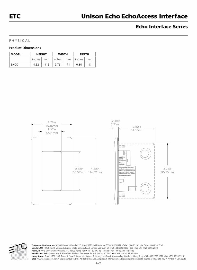
Product Dimensions
MODEL HEIGHT WIDTH DEPTH
inches mm inches mm inches mm
EACC 4.52 115 2.76 71 0.30 8
Corporate Headquarters • 3031 Pleasant View Rd, PO Box 620979, Middleton WI 53562 0979 USA • Tel +1 608 831 4116 • Fax +1 608 836 1736London, UK • Unit 26-28, Victoria Industrial Estate, Victoria Road, London W3 6UU, UK • Tel +44 (0)20 8896 1000 • Fax +44 (0)20 8896 2000Rome, IT • Via Ennio Quirino Visconti, 11, 00193 Rome, Italy • Tel +39 (06) 32 111 683 • Fax +44 (0) 20 8752 8486Holzkirchen, DE • Ohmstrasse 3, 83607 Holzkirchen, Germany • Tel +49 (80 24) 47 00-0 • Fax +49 (80 24) 47 00-3 00Hong Kong • Room 1801, 18/F, Tower 1 Phase 1, Enterprise Square, 9 Sheung Yuet Road, Kowloon Bay, Kowloon, Hong Kong • Tel +852 2799 1220 • Fax +852 2799 9325Web • www.etcconnect.com • Copyright©2016 ETC. All Rights Reserved. All product information and specifications subject to change. 7186L1015 Rev. A Printed in USA 02/16

Unison Echo® Inspire® Control StationsETC®
1 of 5
Echo Control Series
O R D E R I N G I N F O R M A T I O N
Product MODEL DESCRIPTION
E1001-_ Inspire 1-Button Control Station
E1002-_ Inspire 2-Button Control Station
E1004-_ Inspire 4-Button Control Station
E1006-_ Inspire 6-Button Control Station
E1008-_ Inspire 8-Button Control Station
E1104-_ Inspire 4-Button with Fader Control Station
Enter station color code in __ space provided:
1 = Cream (RAL 9001), 4 = Black (RAL 9004), 5 = Signal White (RAL 9003)
Stations flush-mount (F) in industry-standard gang boxes. (By others)
Related EchoConnect Power Supplies
MODEL DESCRIPTION
E-SPM(-A) DRd Station Power Module (24V Aux)
E-SPM-WM(-A) Wall-Mount Station Power Module (24V Aux)
E-SPM-RM(-A) Rack-Mount Station Power Module (24V Aux)
E-SPS Room Station Power Supply
E-APS 24V Aux Power Supply, Knockout Mount
Compatible Stations, Sensors and Interfaces
MODEL DESCRIPTION
ELS/ EOCC Echo Responsive Controls
EOCC Occupancy/ Vacancy Sensor
EPS05/ EPS10 Preset Stations
EACC EchoAccess™ Interface
EDMXC Echo DMX Scene Controller
E-ATC Echo TimeClock
EEB Echo Expansion Bridge
Compatible Output Products
MODEL DESCRIPTION
ERC/EDRC One/Two Zone Relay Controllers
ELD/EDLD One/Two Zone 0-10V Dimming Controllers
ESSC/EDSSC One/Two Zone SmartSpace Controllers
ELVD 600-Watt Phase Adaptive Dimmer
ERMCX Echo Room Controllers
ERP/ERP-FT Echo Relay Panel/Echo Relay Panel Feedthrough
DRd Unison® DRd with Echo Control
SR3 Sensor3 Power Control System
G E N E R A L I N F O R M A T I O N
The control you need – right at your fingertips. These EchoConnect™-powered stations are designed to initiate preset, zone, and space controls for your entire system. They communicate efficiently with dimmers, relays and power control panels to provide necessary control for any installation. You can choose your level of control with a variety of button and fader stations created with your solutions in mind.
APPLICATIONS • Education• Hospitality• Healthcare facilities• Office buildings• Conference rooms• Meeting rooms• Retail
FEATURES• EchoConnect: two-wire topology-free system gives you the
freedom to easily place stations wherever they are needed• Fastener-Free Faceplate System: no visible means of
attachment• Decorator style face places available in one-, two-, three- and
four-gang options• Color condition: rear-illuminated buttons that indicate system
status using blue for active and amber or off for inactive• Simple user-legend system supports use of a variety of
standard nomenclature, or user-supplied insertsGENERAL
• UL and cUL LISTED• CE marked

Unison Echo Inspire Control Stations ETC
2 of 5
Echo Control Series
S P E C I F I C A T I O N S
FUNCTIONAL • Button and fader functions include: preset activation/ deactivation, record, raise, lower, zone on/off control and room combine• Blue button illumination for active status• Amber or no button illumination for inactive status• Fader halo-illumination displays actual output level• Zone or preset control from any station with real-time user toggle
MECHANICAL • Standard configurations with 1, 2, 4, 6 and 8 buttons or 4 buttons and rotary fader• Gangable for custom applications• Enclosed electronics assembly and faceplate included• Cantilevered switch arrays with removable button caps• No visible means of attachment • Flush-mount in industry standard backbox, RACO 690 or equivalent• Surface-mount backboxes available from ETC upon request• Constructed of injection-molded, ABS plastic in three RAL standard colors Cream (RAL 9001), Black (RAL 9004), and White (RAL 9003)• User configurable legends on each button, or use standard legends that come with each station. Field configurable without the use of
tools • Integral LED response indicator for each button with indication of active(blue) and inactive(amber or off) state
ELECTRICAL • Connect via the EchoConnect control network via low-voltage Class 2 wiring• Topology-free wiring over Belden 8471 or equivalent and one #14 ESD drain wire• Supports optional use of Belden 1583A or equivalent Ethernet control wire when used with Cat5 termination accessories• Wiring may be bus, loop, homerun or any combination of these• Supports up to 500 meters (1640 feet) of control wiring
- Up to 1000’ using CAT5• All station terminations utilize removable connectors• UL and cUL LISTED, CE marked
THERMAL • Ambient room temperature: 0-50°C / 32-122°F• Ambient humidity: 5-95% non-condensing

Unison Echo Inspire Control Stations ETC
3 of 5
Echo Control Series
SMALL SYSTEM
MEDIUM SYSTEM
CONFERENCE ROOM

Unison Echo Inspire Control Stations ETC
4 of 5
Echo Control Series
MEDIUM BALLROOM

Unison Echo Inspire Control Stations ETC
5 of 5
Echo Control Series
P H Y S I C A L
Product Dimensions
MODEL HEIGHT WIDTH DEPTH
inches mm inches mm inches mm
E100X 4.52 115 2.76 71 0.30 8
E1104 4.52 115 2.76 71 0.55 14
Corporate Headquarters • 3031 Pleasant View Rd, PO Box 620979, Middleton WI 53562 0979 USA • Tel +1 608 831 4116 • Fax +1 608 836 1736London, UK • Unit 26-28, Victoria Industrial Estate, Victoria Road, London W3 6UU, UK • Tel +44 (0)20 8896 1000 • Fax +44 (0)20 8896 2000Rome, IT • Via Ennio Quirino Visconti, 11, 00193 Rome, Italy • Tel +39 (06) 32 111 683 • Fax +44 (0) 20 8752 8486Holzkirchen, DE • Ohmstrasse 3, 83607 Holzkirchen, Germany • Tel +49 (80 24) 47 00-0 • Fax +49 (80 24) 47 00-3 00Hong Kong • Room 1801, 18/F, Tower 1 Phase 1, Enterprise Square, 9 Sheung Yuet Road, Kowloon Bay, Kowloon, Hong Kong • Tel +852 2799 1220 • Fax +852 2799 9325Web • www.etcconnect.com • Copyright©2016 ETC. All Rights Reserved. All product information and specifications subject to change. 7186L1009 Rev. G Printed in USA 09/16
2.76”70.1mm
2.63”66.8mm
2.50”63.5mm
3.75”95.3mm
4.52”114.9mm
1.32”33.6mm

Unison Echo-Echoflex InterfaceETC®
1 of 3
Echo Interface Series
O R D E R I N G I N F O R M A T I O N
Product MODEL DESCRIPTION
EEI Echo-Echoflex Interface
AccessoriesMODEL DESCRIPTION
EEI-EA External Antenna Kit
ECHO-DIN Echo Low-Voltage DIN-Rail Cover Kit
Related EchoConnect Power SuppliesMODEL DESCRIPTION
E-SPM(-A) DRd Station Power Module (24V Aux)
E-SPM-WM(-A) Wall-Mount Station Power Module (24V Aux)
E-SPM-RM(-A) Rack-Mount Station Power Module (24V Aux)
E-SPS Room Station Power Supply
E-APS 24V Aux Power Supply, Knockout Mount
Compatible Stations, Sensors and InterfacesMODEL DESCRIPTION
E100X Inspire Button Stations
E1104 Inspire Fader Stations
EPS05/ EPS10 Preset Stations
ELS Light Sensor
EOCC Occupancy/ Vacancy Sensor
EACC EchoAccess™ Interface
EDMXC Echo DMX Scene Controller
E-ATC Echo TimeClock
EEB Echo Expansion Bridge
Compatible Output ProductsMODEL DESCRIPTION
ERC/EDRC One/Two Zone Relay Controllers
ELD/EDLD One/Two Zone 0-10V Dimming Controllers
ESSC/EDSSC One/Two Zone SmartSpace Controllers
ELVD 600-Watt Phase Adaptive Dimmer
ERMCX Echo Room Controllers
ERP/ERP-FT Echo Relay Panel/Echo Relay Panel Feedthrough
DRd Unison® DRd with Echo Control
SR3 Sensor3 Power Control System
G E N E R A L I N F O R M A T I O N
The Unison Echo-Echoflex Interface allows for wireless communication between Unison Echo® and Echoflex control systems. When it’s not practical to run wires between every device in your building’s control system, the Echo-Echoflex Interface is the solution. Using the built-in 902 MHz radio the Echo-Echoflex Interface can transmit or receive wireless signals to communicate with any Echoflex control device within 80 feet (24 meters). And since the Echo-Echoflex Interface is a DIN-rail-mount device, you can install it nearly anywhere.
APPLICATIONS • Retrofits • Hospitality• Healthcare facilities • Conference and meeting rooms• Retail• Houses of worship
FEATURES• Four Echoflex product inputs to trigger Echo Presets• Four Echo zone outputs to control Echoflex power products• Onboard configuration and testing tools • Input and output status indicators• EchoConnect™: two-wire topology-free system gives you the
freedom to easily place devices wherever they are needed• Optional external antenna kit available
GENERAL• UL and cUL LISTED• CE Marked

Unison Echo-Echoflex InterfaceETC
2 of 3
Echo Interface Series
S P E C I F I C A T I O N S
FUNCTIONAL • Receives wireless trigger from Echoflex system and translates it into an Echo preset trigger• Receives zone level from Echo system and translates it into a wireless Echoflex command• Compatible with Echo stations, senors, interfaces and power controllers• Compatible with Echoflex station, sensors and a power controllers
MECHANICAL • Buttons and LED indicators for wireless inputs and wired output configuration and status• Din-rail mounting complies with DIN43880 (35/7.5 rail)• Constructed of injection-molded black ABS plastic• Connection for external antenna (provided separately)
ELECTRICAL • Connects via two-wire EchoConnect control network through low-voltage Class 2 wiring + 24VDC auxiliary power
- Topology-free wiring over Belden 8471 or equivalent and one #14 ESD drain wire - Two #16 AWG wires for 24VDC auxiliary power
• Wiring may be bus, loop, homerun or any combination of these• Supports optional use of Belden 1583A or equivalent Ethernet control wire when used with Cat5 termination accessories• Supports up to 500 meters (1,640 feet) of control wiring
- Up to 300 meters (1,000 feet) using Cat5• MicroSD card slot for firmware maintenance• 902 MHz wireless radio• 80-foot (24-meter) open-air transmission range• UL and cUL Listed, CE Marked• UL2043 LISTED for use in plenum
THERMAL • Ambient room temperature: 0-50°C / 32-122°F• Ambient humidity: 5-95% non-condensing

Unison Echo-Echoflex InterfaceETC
3 of 3
Echo Interface Series
P H Y S I C A L
Product Information
MODEL HEIGHT WIDTH DEPTH WEIGHT
inches mm inches mm inches mm lbs kgs
EEI 3.5 90 3.0 76 1.0 25 0.22 0.10
Corporate Headquarters • 3031 Pleasant View Rd, PO Box 620979, Middleton WI 53562 0979 USA • Tel +1 608 831 4116 • Fax +1 608 836 1736London, UK • Unit 26-28, Victoria Industrial Estate, Victoria Road, London W3 6UU, UK • Tel +44 (0)20 8896 1000 • Fax +44 (0)20 8896 2000Rome, IT • Via Ennio Quirino Visconti, 11, 00193 Rome, Italy • Tel +39 (06) 32 111 683 • Fax +44 (0) 20 8752 8486Holzkirchen, DE • Ohmstrasse 3, 83607 Holzkirchen, Germany • Tel +49 (80 24) 47 00-0 • Fax +49 (80 24) 47 00-3 00Hong Kong • Room 1801, 18/F, Tower 1 Phase 1, Enterprise Square, 9 Sheung Yuet Road, Kowloon Bay, Kowloon, Hong Kong • Tel +852 2799 1220 • Fax +852 2799 9325Web • www.etcconnect.com • Copyright©2016 ETC. All Rights Reserved. All product information and specifications subject to change. 7186L1018 Rev. A Printed in USA 05/16

ERDRC-FD
Dimming Controller
F series
This guide covers the “F” series of the Dimming Controller, model numbers ERDRC-FDU-120/277 for input voltages of 120 or 277VAC and ERDRC-FDU-120/347 for input voltages of 120 or 347VAC. Both models are equipped with a 902 MHz radio.The box contents includes the controller with lock nut and installation guide.
Product OverviewThe ERDRC-FDU controller is intended for indoor use only. The Dimming Controller uses wireless technology to monitor any room’s environment, eliminating much of the wiring normally required for distributed lighting control. This translates into quick installations with less disruption to occupants, allowing facilities to accelerate retrofit schedules and start saving money sooner. The controller has patented Smart Click and Simple Tap technology which allows installers and facility operators to manage configuration settings without any tools, reducing call-backs and installation expense.

2
Controller OperationThe controller can activate lighting loads with received input from a linked sensor or switch. As a lighting controller, it operates lights based on:
• ambient light levels monitored by an wireless photo sensor• occupancy state monitored by a wireless occupancy sensor• switch action from a wireless wall switch• gateway control implementing scheduled or other events
The controller will fade lights up or down using the dimming output for a switched ON or OFF event. The controller can also be configured to fade lights based on an occupancy sensor ON or OFF event.The controller automatically detects when the dimming lines are connected to a current sourcing load. When the purple and gray dimming interface wires are un-connected, the dimming interface is disabled and fade timers are removed so the relay’s action is immediate upon the ON/OFF event. The controller does support current sinking loads configurable using Garibaldi commissioning software. To determine if the load is current sinking or sourcing, refer to the fixture documentation under the ballast or driver specifications.Changing the fade rates is possible using the Garibaldi configuration software.
Controller and Wall SwitchesThe controller works with the wireless single and dual rocker, wave and hand held switches. A switch ON action activates the relay closed (lights on) and the dimming output will increase to the last dim level. A quick double-press ON will fade up to maximum light output and accelerate the fade period to ½ second. A press OFF action will fade the lights down and then open the relay (lights off). A quick double-press OFF will accelerate the fade period to ½ second.Echoflex switches can also be used as dimmer switches – press and hold the on or off side to modulate the dimming output up or down.
Controller and Timed SwitchesThe controller can be configured so the single and dual rocker switches become timed switches. An ON action closes the relay (lights on) and a timer is set to count down. Once the timer expires, the relay opens (lights off).The time period is configurable and has 5 settings: no timer (default), 5 minutes, 15 minutes, 30 minutes and 1 hour. Additionally, if the user presses the wall switch ON multiple times ( to a total of 5 presses), the timer interval is added for each ON press. If ON is pressed while the light’s are on and the timer is counting down, an additional period of time is added to the timer total.Example: if the timer setting is 1 hour and the user pressed the switch ON twice, the total timer period is 2 hours. If there is 30 minutes left on the timer and ON is pressed again, the timer is extended to 1 hour 30 minutes before the light’s will turn off.

3
The controller will toggle the relay (flick-warn) 1 minute before the timer is due to expire to warn users of the pending OFF event.To configure, the time period, refer to the section on ”Configuring the Controller”.
Occupancy Based Lighting ApplicationsThe controller will turn the lights OFF when there is no motion detected in the room indicated by a linked motion sensor. If the application requires the lights to remain ON during vacant periods but at a dimmed level (i.e. warehouse or stairwell applications), a configuration property accessible using Garibaldi software can enable this feature.Occupancy sensors only: When only occupancy sensors are linked to the controller, the sensor will automate the lights both ON and OFF.Occupancy sensors with switches: When switches and sensors are linked, the controller will assume manual-ON, auto-OFF operation referred to as Vacancy Sensor Mode.The controller can also be configured to turn the lights ON immediately (Auto-ON) with motion, see the section titled “Configuring the Controller”. Photo Inhibit: This feature requires a linked photo sensor. When photo-inhibit is enabled, the Auto-ON feature will be ignored when the natural light level measured by the light sensor is above the day-lighting set point. The photo inhibit feature will not turn lights OFF if the lights are ON.Photo Inhibit Examples:
• Light level is < day-lighting set point – The lights do turn ON automatically when you enter the room.
• Light level is > day-lighting set point – The lights do not turn ON automatically when you enter the room.
• Lights are ON and the light level increases past day-lighting set point – The lights stay ON.
• Lights are OFF and the light level decreases past day-lighting set point – The lights will turn ON upon the next motion detected by the occupancy sensor.
Daylight Harvesting ApplicationsThe controller will modulate the light intensity from a dimming fixture based on the ambient light level in the room. A wireless photo sensor monitors light levels and must be linked to the controller to provide the light level in the room. The daylight control application has several variables:
• Maximum dimming level - the highest level the dimming output will reach. • Minimum dimming level - the lowest level the dimming output will reach. • Lighting set point - the daylight control set point serves two purposes,
closed loop control and open loop control.

4
Closed Loop Control - When the controller is configured for daylight harvesting and set to closed loop control, the set point becomes the absolute value in percent of light the controller will try to attain.Closed Loop Daylight Control example: A project specification item details that a certain value of light must be measured on a desktop. The dimming light fixture providing light to the desktop is controlled. The light sensor is located over the desk facing downwards. Place a hand-held light sensor on the desktop and using a linked switch, dim the lights up or down until the sensor matches the specification value. Use Simple Tap to capture the light level as the daylight control set point.NOTE: This process is best performed when there is no natural light; either close the blinds or complete this step at night.
Open Loop Control - When the controller is configured for daylight harvesting and set to open loop control, the set point is where the dimming output begins to dim the fixture as the natural light increases. NOTE: The TAP light sensor is designed to be mounted indoors to monitor reflected (not direct) natural light levels.
Open Loop Daylight Control example: A project requirement item details that the open area office lights shall dim down when sufficient natural light is present. Mount the wireless light sensor so it is facing downwards and monitoring reflected natural light. The Echoflex light sensor has two ranges; 0-500 lux (0-50 foot-candles) and 0-1024 lux (0-100 foot-candles). The lighting
set point default value is 60% of the sensors Full Scale Range (FSR). If the range is set to 50FC (500 lux), the controller will begin dimming down when the sensor records 30FC (300 lux) and will reach the minimum dimming level at 100% or 50FC (500 lux).Setting the set point is covered later in this document under “Configuring the Controller”. The daylight harvesting application will override the Auto-ON feature of occupancy sensors if the light level is sufficient and calls for the lights to be off. The daylight harvesting application can be overridden by a manual wall switch when the light is off by clicking on. If the light level remains above the Light-OFF-Set point, the controller will turn the light off again after 250 seconds.

5
The daylight harvesting application does not affect the operation of the wall switch or motion sensor when the light is on. If the light is on, either the switch or motion sensor can override the light off.See the section on Occupancy Based Lighting Application - Photo-inhibit for alternative functionality.
Radio Range ConfirmationThe “F series” controllers includes patent pending technology that works with all Echoflex sensors equipped with the range confirmation feature to provide visual feedback of a linked sensors signal strength for optimal sensor placement.To evaluate the radio signal strength, the sensor must be also support the test and be linked to the controller. Check the sensors documentation to find out if it supports radio range confirmation testing. Do not have any repeaters in the controllers vicinity enabled during the test.The range confirmation test is invoked at the sensor and sends unique telegrams to the controller. The controller will evaluate the signal strength from the sensor and send back a unique telegram containing the strongest signal value received. This value is displayed at the sensor using color LEDs. Consult the sensor installation guide for more details.
Important Safety InstructionsWARNING: ELECTRICAL SHOCK HAZARD - THE CONTROLLER USES HIGH VOLTAGE AND SHOULD ONLY BE INSTALLED BY A QUALIFIED INSTALLER OR ELECTRICIAN. FOLLOW ALL APPLICABLE ELECTRICAL CODES IN THE COUNTRY
OF INSTALLATION. INDOOR USE ONLY.
Preparing to Install the ControllerThe controller is mounted to an electrical junction box or panel with a ½” threaded nipple. The controller must be mounted on the outside of a junction box either directly at the electrical load or before the load in the circuit. The controller is for indoor use only. You will require hand tools to gain access to the junction box and remove any cover plates or other hardware.NOTE: If the circuit will have an additional hard wired switch, wire the controller in series before the switch.
Installing the ControllerReview these instructions completely before installing the controller.
1. Locate the circuit breaker panel and turn off the power to the circuit.2. Remove all face plates and other hardware from the junction box so you
can access the high voltage wires.3. The controller is mounted to the exterior of the junction box or panel with
the ½” threaded nipple.4. Refer to the wiring diagram to connect the controller to the line power,
neutral and load wires. Use wire nuts on all connections and cap any bare wires.

6
5. Replace the junction box faceplate.6. Restore power to the circuit.7. Refer to the section in this guide titled LEARN Button to assign a switch
to the controller. Alternatively, refer to the Smart Click instructions for assigning switches remotely.
Controller Wiring Diagram Line Voltage choose either Black 120V line power or Commercial Voltage (Brown - 277V
on model ERDRC-FDU-120/277) or (Yellow - 347V on model ERDRC-FDU-120/347) -Low voltage wiring is optional.
TIP: To link the first switch; triple click a wireless wall switch 3 times ON, followed by triple click OFF, then again triple click ON, all within 5 seconds. Use this switch to verify
the controller relay is turning the lights on and off.Wiring InstructionsPower to the controller is connected between the White (Neutral) and the Black (120V) Line power. Optionally, commercial voltages can be applied between the White (Neutral) and the models commercial voltage: Brown(277V) or Yellow(347V) .The controller has an orange external antenna. Do not cut, cap or connect this wire.Use only approved wire. Cap off all unused wires except the antenna wire. The violet and gray lines can be used to provide 0-10V control of a dimming ballast
Connection Color SpecificationLOAD x 2 Red 14AWG, 600VNeutral White 18AWGLine 120VAC Black 18AWGLine 277VAC Brown 18AWGLine 347VAC Yellow 18AWGDimming 0-10V Violet 22AWGDimming GND Grey 22AWG
Diagnostic LED’s and buttonsLEARN button The LEARN button is used to link switches or sensors to the controller.
Load 1
White (Neutral)
ERDRC-FDU
Red (Load)
Red (Line)
DimmingBallast
Grey0-10 V
Violet0-10 V
do not cut or removeOrange - antenna
White
Black
N
347V
120V
Brown Yellow277V
60 Hz
5 Watts
Max
White (Neutral)
Load 2
DimmingBallast
Red
(Load)
HOT
AdditionalDimming Ballast(s)
AdditionalSwitchedLoad(s)
18AWG
14AWG
600V
/OR
22AWG
7
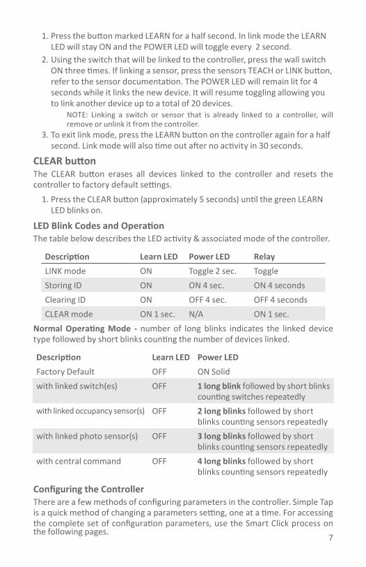
1. Press the button marked LEARN for a half second. In link mode the LEARN LED will stay ON and the POWER LED will toggle every 2 second.
2. Using the switch that will be linked to the controller, press the wall switch ON three times. If linking a sensor, press the sensors TEACH or LINK button, refer to the sensor documentation. The POWER LED will remain lit for 4 seconds while it links the new device. It will resume toggling allowing you to link another device up to a total of 20 devices.
NOTE: Linking a switch or sensor that is already linked to a controller, will remove or unlink it from the controller.
3. To exit link mode, press the LEARN button on the controller again for a half second. Link mode will also time out after no activity in 30 seconds.
CLEAR button The CLEAR button erases all devices linked to the controller and resets the controller to factory default settings.
1. Press the CLEAR button (approximately 5 seconds) until the green LEARN LED blinks on.
LED Blink Codes and OperationThe table below describes the LED activity & associated mode of the controller.
Description Learn LED Power LED RelayLINK mode ON Toggle 2 sec. ToggleStoring ID ON ON 4 sec. ON 4 secondsClearing ID ON OFF 4 sec. OFF 4 secondsCLEAR mode ON 1 sec. N/A ON 1 sec.
Normal Operating Mode - number of long blinks indicates the linked device type followed by short blinks counting the number of devices linked.
Description Learn LED Power LEDFactory Default OFF ON Solidwith linked switch(es) OFF 1 long blink followed by short blinks
counting switches repeatedlywith linked occupancy sensor(s) OFF 2 long blinks followed by short
blinks counting sensors repeatedlywith linked photo sensor(s) OFF 3 long blinks followed by short
blinks counting sensors repeatedlywith central command OFF 4 long blinks followed by short
blinks counting sensors repeatedly
Configuring the ControllerThere are a few methods of configuring parameters in the controller. Simple Tap is a quick method of changing a parameters setting, one at a time. For accessing the complete set of configuration parameters, use the Smart Click process on the following pages.
8
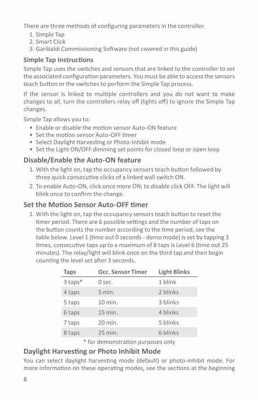
There are three methods of configuring parameters in the controller. 1. Simple Tap2. Smart Click3. Garibaldi Commissioning Software (not covered in this guide)
Simple Tap Instructions Simple Tap uses the switches and sensors that are linked to the controller to set the associated configuration parameters. You must be able to access the sensors teach button or the switches to perform the Simple Tap process. If the sensor is linked to multiple controllers and you do not want to make changes to all, turn the controllers relay off (lights off) to ignore the Simple Tap changes.Simple Tap allows you to:
• Enable or disable the motion sensor Auto-ON feature• Set the motion sensor Auto-OFF timer• Select Daylight Harvesting or Photo-Inhibit mode• Set the Light ON/OFF dimming set points for closed loop or open loop
Disable/Enable the Auto-ON feature 1. With the light on, tap the occupancy sensors teach button followed by
three quick consecutive clicks of a linked wall switch ON. 2. To enable Auto-ON, click once more ON; to disable click OFF. The light will
blink once to confirm the change.
Set the Motion Sensor Auto-OFF timer1. With the light on, tap the occupancy sensors teach button to reset the
timer period. There are 6 possible settings and the number of taps on the button counts the number according to the time period, see the table below. Level 1 (time out 0 seconds - demo mode) is set by tapping 3 times, consecutive taps up to a maximum of 8 taps is Level 6 (time out 25 minutes). The relay/light will blink once on the third tap and then begin counting the level set after 3 seconds.
Taps Occ. Sensor Timer Light Blinks3 taps* 0 sec. 1 blink4 taps 5 min. 2 blinks5 taps 10 min. 3 blinks6 taps 15 min. 4 blinks7 taps 20 min. 5 blinks8 taps 25 min. 6 blinks
* for demonstration purposes onlyDaylight Harvesting or Photo Inhibit ModeYou can select daylight harvesting mode (default) or photo-inhibit mode. For more information on these operating modes, see the sections at the beginning

9
of this guide titled Occupancy Based Lighting Applications – Photo Inhibit and Daylight Harvesting Application. A light sensor and wall switch must be linked to the controller before proceeding.
1. Press the photo sensors TEACH button once followed by clicking the switch ON three times within 5 seconds.
2. Either:• click the switch once more ON to activate Photo-Inhibit operating mode.• or click the switch once OFF to activate Daylight harvesting operating
mode.The set point values are a percentage of the full range of the linked photo sensor.
Set the Lighting Set PointThe controller will turn the light on and off or will modulate the dimming output (if enabled) based on the measured light level from the light sensor. The lighting set point is used to adjust how the dimming and relay respond to the relative light levels.There are two methods of setting the set-point.
1. Closed LoopYou can use the light sensor to function as a closed loop sensor. When set as a closed loop sensor, the controller will dim the lights until the light level recorded at the sensor meets the set point value. For more information on this operating mode, see the section at the beginning of this guide titled Daylight Harvesting Application. A light sensor must be linked to the controller before proceeding.NOTE: This process is best performed when there is no natural light; either close the blinds or complete this step at night.
1. With the light on, adjust the light level from the fixture using the switch until it matches the desired light level.
2. Tap the light sensor’s teach button 3 times to set the daylight harvesting parameters to a closed loop function. The light will blink once to acknowledge the change.
Open LoopThe lighting set-point can be set to an absolute value useful in open-loop sensor applications. If the dimming output is enabled, the absolute value selected becomes the maximum dimming set-point. If the output is disabled, the absolute value selected becomes the Light ON Set point, see the table below.
1. With the light on, tap the light sensors teach button 4 times to set the set point to 20%.
2. Tap the button additional times incrementing the set point value by 20%. Five (5) taps would equal 40%, seven (7) taps would be 80%.
3. The light will blink once at three taps and then begin blinking according to the level set to confirm the change after 3 seconds.

10
Dimming Output EnabledTaps Max. Dim SP Min. Dim SP Blinks4 taps 20% 100% 2 blinks5 taps 40% 100% 3 blinks6 taps 60% 100% 4 blinks7 taps 80% 100% 5 blinks
Dimming Output DisabledTaps Light ON Light OFF Blinks4 taps 20% 40% 2 blinks5 taps 40% 60% 3 blinks6 taps 60% 80% 4 blinks7 taps 80% 100% 5 blinks
Using Smart Click to Configure the ControllerConfiguring the controller requires that at least one wireless wall or hand held switch is linked to the controller. The Smart Click menu includes these parameters: Level 1 Learn Mode Level 2 Clear Switch/Clear All Level 3 Repeater Function Level 4 Status Telegram Function Level 5 Time out Periods Level 6 Auto-ON with Motion Function Level 7 Dimming Output Function Level 8 Daylight Harvesting Set-point Level 9 Maximum Dimming Output Level 10 Minimum Dimming Output
Linking the First SwitchUsing this method of linking a switch will only work if the controller does not have any other linked devices. Use the learn button or Smart Click to link additional switches.
1. Press the CLEAR button until the green LEARN led blinks ON, about 6 seconds.
2. With the controller cleared or in the factory default state, click the wireless switch ON three times, OFF three times and ON three times quickly within 5 seconds. The red POWER led will begin a blinking pattern [one long followed by one short], see the section on LED blink codes.
Entering Smart Click Configuration ModeIt is important to have feedback (attached light) from the controller during configuration. Perform the configuration changes when the controller has been

11
installed on a lighting circuit. The switch used to configure a controller using Smart Click should only be linked to the controller you’re configuring. Add an additional switch if necessary.
1. Using a linked switch (see above), turn the light OFF. 2. Press the switch OFF, and hold until the light turns on, about 10 seconds. 3. Press ON until the light blinks, about 5 seconds. The light will repeatedly
blink once every 5 seconds indicating it is at level 1 of Smart Click.NOTE: You can exit Smart Click at any time by pressing OFF for 5 seconds.
Level 1 - Linking an additional switch or sensor1. Enter Smart Click configuration mode and with the light blinking once,
press ON for 3 seconds. The light will begin blinking ON/OFF faster, once every second.
2. Add additional wireless switches by clicking the new switch ON 3 times quickly. Add sensors by pressing the TEACH or LINK button on the sensor.
3. To exit Smart Click press OFF for 5 seconds.Level 2 - Clear switches or sensors (restore factory defaults)
1. Enter Smart Click configuration mode and click the switch ON once so the light is blinking twice.
2. Press ON for three seconds.3. Click the switch ON 5 times to clear the switch, click ON 5 times again to
clear ALL switches and sensors and reset the controller to factory defaults.4. Press OFF for 5 seconds to complete clearing and exit Smart Click.
Level 3 - Repeater Function - repeats any telegram within range.The repeater function can be enabled/disabled by accessing the controller buttons.
1. Press the Clear button and hold, then quickly press the Learn button; once to disable, twice to enable single hop and three times to enable dual hop repeating. The learn LED will blink the corresponding value of the LEARN button presses.
2. Release the Clear button.If there is no access to the controllers buttons, follow these Smart Click steps.
1. Enter Smart Click configuration mode and click the switch ON twice until the light is blinking three times.
2. Press ON for 3 seconds. If the repeater function is enabled the light will turn ON, if disabled the light will be OFF.
3. Click ON to activate the single hop repeating function , OFF to deactivate. There is no selection for enabling dual hop repeating with Smart Click.
4. Exit Smart Click by pressing OFF for 5 seconds.Level 4 - Status Telegram - the controller can broadcast a status telegram per EEP: A5-11-01. The telegram will broadcast every 100 seconds.. If the controller has a wired occupancy sensor connected to the low voltage input, this sensor

12
status can be shared with other controllers. The controller must be first linked with the receiving controllers.Enabling the status telegram activates the shared occupancy feature and also sends the learn command to the other controllers for linking. The status telegram can be enabled/disabled by accessing the controller buttons. 1. Press the Learn button and hold, press the Clear button once to disable, twice to enable (this sends the learn telegram). 2. Release the Learn button. The learn LED will blink once when disabling, twice when enabling this telegram.If there is no access to the controllers buttons, follow these Smart Click steps.
1. Enter Smart Click Configuration Mode and click the switch three times until the light is blinking four times.
2. Click ON for 3 seconds. If the status telegram function is enabled the light will turn ON, if disabled the light will be OFF.
3. Click ON to activate this function, OFF to deactivate.4. Exit Smart Click by pressing OFF for 5 seconds.
Level 5 - Timeouts - the controller can be configured to wait a period of time after an ON event from a wireless switch or occupancy sensor before turning the load OFF (auto off).
1. Enter Smart Click Configuration Mode and click the switch ON four times until the light is blinking five times.
2. Press ON for 3 seconds. The light will turn OFF and then ON per the table settings below.
3. Using the linked switch, click ON to increase the timeout or OFF to decrease the timeout, in 5 minute increments.
4. Exit Smart Click by pressing OFF for 5 seconds.
Light Timed Switch Occ. Sensor Timer
OFF no auto-off 0 sec. (demo)
1 Blink 5 min. 5 min.
2 Blinks 15 min. 10 min.
3 Blinks 30 min. 15 min.
4 Blinks 60 min. 20 min.
5 Blinks N/A 25 min.Level 6 - Auto ON Function - use with a motion sensor to turn lights ON automatically when motion is detected. If a motion sensor is used with no switch then Auto-ON is enabled automatically. If a switch is linked later, Auto-ON is disabled.
1. Enter Smart Click Configuration Mode and click the switch ON five times until the light is blinking six times.
2. Press ON for 3 seconds. If the auto-on function is enabled the light will turn

13
ON, if disabled the light will be OFF.3. Click ON to activate this function, OFF to deactivate.4. Exit Smart Click by pressing OFF for 5 seconds.
Level 7 - Dimming Ballast Output -Enables or disables the dimming ballast output.
1. Enter Smart Click Configuration Mode and click the switch ON or OFF until the light is blinking seven times.
2. Press ON for 3 seconds. If the dimming output is enabled the light will turn ON, if disabled the light will be OFF
3. Click ON to activate this function, OFF to deactivate.4. Exit Smart Click by pressing OFF for 5 seconds.
Level 8 - Lighting Set point - The set point is a single value that can affect how the controller manages the light output depending on if the controller is setup for daylight harvesting or photo inhibit applications. When set for photo inhibit operation, the Auto-ON feature associated with a linked occupancy sensor will be ignored when the natural light level measured by the light sensor is above the lighting set point. The photo inhibit feature will not turn lights OFF if the lights are ON.Photo Inhibit Examples:
• Light level is < day-lighting set point – The lights do turn ON automatically when you enter the room.
• Light level is > day-lighting set point – The lights do not turn ON automatically when you enter the room.
• Lights are ON and the light level increases past day-lighting set point – The lights stay ON.
• Lights are OFF and the light level decreases past day-lighting set point – The lights will turn ON upon the next motion detected by the occupancy sensor.
When set for daylight harvesting operation, the set-point is used with a photo sensor (light sensor) and will automatically turn lights on and off or modulate dimming fixtures depending on ambient light levels. You can use the light sensor to function as a closed loop sensor. When set as a closed loop sensor, the controller will dim the lights until the light level recorded at the sensor meets the set-point value. For more information on this operating mode, see the section at the beginning of this guide titled Daylight Harvesting Application. If the light from the fixture does not impact the light reading at the sensor then it is an open loop application. When the dimming output is enabled, the value selected becomes the maximum dimming set point. With the dimming output disabled, the value becomes the Light-ON-Set point.

14
Control Response with Dimming Output EnabledIn the diagram below, the blue line indicates the dimming output. The output will begin lowering as the natural light level increases (green line). The point where the light output begins dimming down is the lighting set point (default 60% sensor FSR). The minimum dimming level is set to 100% sensor FSR.
Control Response with Dimming Output DisabledIn the diagram below, the blue line indicates the fixture light output. As the natural light increases (green line), the relay will open at a level 20% greater than the set point value (default 60% sensor FSR). As the natural light decreases, the relay will close once the light level decreases past the light set point.
To adjust the light set-point:1. Enter Smart Click Configuration Mode and click the switch ON seven times until
the light is blinking eight times.2. Press ON for 3 seconds. Default setting is 60% of the light sensors full scale
range. There are 4 steps from 20% to 80%. The light will blink the step count. (see table below). Click on to increase the set-point, off to decrease the set-point.
BlueGreen
Blue
Green
BlueGreen
Blue
Green

15
Dimming Output EnabledTaps Max. Dim SP Min. Dim SP Blinks
4 taps 20% 100% 2 blinks5 taps 40% 100% 3 blinks6 taps 60% 100% 4 blinks7 taps 80% 100% 5 blinks
Dimming Output DisabledTaps Light ON Light OFF Blinks
4 taps 20% 40% 2 blinks5 taps 40% 60% 3 blinks6 taps 60% 80% 4 blinks7 taps 80% 100% 5 blinks
3. Exit Smart Click by pressing OFF for 5 seconds.Level 9 - Maximum Dimming Output Level - sets the maximum level of the dimming output.
1. Enter Smart Click Configuration Mode and click the switch ON eight times until the light is blinking nine times.
2. Press ON for 3 seconds. Default setting is 100%. Adjust the maximum light level to the brightness level desired by clicking ON to increase and OFF to decrease in 2% increments.
3. Exit Smart Click by pressing OFF for 5 seconds.Level 10 - Minimum Dimming Output Level - sets the minimum level of the dimming output.
1. Enter Smart Click Configuration Mode and click the switch ON nine times until the light is blinking ten times.
2. Press ON for 3 seconds. Default setting is 9%. Adjust the min. light level to the brightness level desired by clicking ON to increase and OFF to decrease in 2% increments.
3. Exit Smart Click by pressing OFF for 5 seconds.
This concludes the configuration directions for the controller.

16
Default Settings for Controller Repeater disabled Status disabled Dimming Output auto-detect for current sourcing loads Motion sensor Time-out 15 minutes Switch Time-out no time out Auto-ON enabled with no linked switch, disabled with linked wall switch Light-ON-Set point 60% of sensor FSR Light-OFF-Set point 100% of sensor FSR with dimming enabled 80% of sensor FSR will dimming disabled Maximum Dimming Level 100% Minimum Dimming Level 9% Grace Timer 30 seconds Status Feedback Telegram EEP:A5-11-01 DB_3 Illumination 0 510lx, linear n=0…255 DB_2 illumination Set Point Min. … Max., linear n=0…255 DB_1: Dimming Output Level Min. … Max., linear n=0…255 DB_0.BIT_7: Repeater 0b0 disabled, 0b1 enabled DB_0.BIT_6: Power Relay Timer 0b0 disabled 0b1 enabled DB_0.BIT_5: Daylight Harvesting 0b0 disabled 0b1 enabled DB_0.BIT_4: Dimming 0b0 switching load 0b1 dimming load DB_0.BIT_3: Learn button 0b0 Teach-in telegram 0b1 Data telegram DB_0.BIT_2: Magnet Contact 0b0 open 0b1 closed DB_0.BIT_1: Occupancy 0b0 unoccupied 0b1 occupied DB_0.BIT_0: Power Relay 0b0 off 0b1 on
ListingsCEC Title 24 compliantETL Listed Component Conforms to UL Standard 508 Certified to CAN/CSA Std C22.2 No.14 UL 2043 Plenum rated
Regulatory Statements FCC Part 15.231 Contains FCC ID: SZV-TCM320U The enclosed device complies with Part 15 of the FCC Rules. Operation is subject to the following two conditions: (I.) this device may not cause harmful interference and (ii.) this device must accept any interference received, including interference that may cause undesired operation. IC RSS-210 Contains IC:5713A-TCM320U
Echoflex Solutions, Inc.#1, 38924 Queens Way | Squamish | BC | Canada | V8B 0K8Toll Free: 888-324-6359 | Phone: (778) 733-0111 | Fax: (604) 815-0078Email: [email protected] | www.echoflexsolutions.com
Copyright 2016 Echoflex Solutions, Inc. | Specifications subject to change without notice.Document #8DC-5377 | Revision 1.3| 8189M21-5694-1 | Rev D

This guide covers all models of MOS-IR and MOS-DT ceiling occupancy sensor.
The MOS-IR product family includes:
MOS-IR-xA Motion sensor with small motion short range lens (1000 sq. ft.)MOS-IR-xB Motion sensor with large motion large range lens (1900 sq. ft.)MOS-IR-xC Motion sensor with high bay lens (6300 sq. ft.)
The MOS-DT product family includes:
MOS-DT-xA Motion and audio sensor with small motion short range lens (1000 sq. ft.)MOS-DT-xB Motion and audio sensor with large motion large range lens (1900 sq. ft.)
Where x is the frequency of the unit: U=902 MHz, Y=868 MHz and J=928 MHz.The package includes the occupancy sensor, lens mask sticker and installation guide.
These Occupancy Sensors are intended for indoor use only in a dry location.
MOS-IR/DT
Wireless Ceiling Mount Sensor for Occupancy / Vacancy Detection
INSTALLATION GUIDE
NOTE: The MOS is a solar powered device that absorbs solar energy storing it for use during low light periods. Before assigning the MOS device to a receiver/controller, the device should be exposed to a good light source for a minimum of 5 minutes or install the start assist battery.
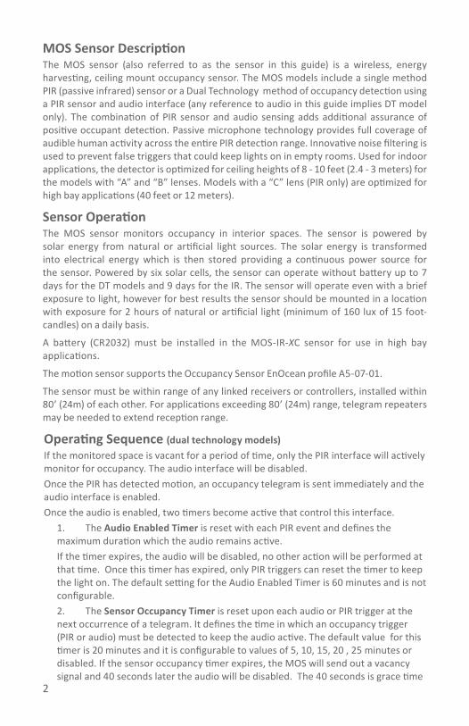
2
MOS Sensor DescriptionThe MOS sensor (also referred to as the sensor in this guide) is a wireless, energy harvesting, ceiling mount occupancy sensor. The MOS models include a single method PIR (passive infrared) sensor or a Dual Technology method of occupancy detection using a PIR sensor and audio interface (any reference to audio in this guide implies DT model only). The combination of PIR sensor and audio sensing adds additional assurance of positive occupant detection. Passive microphone technology provides full coverage of audible human activity across the entire PIR detection range. Innovative noise filtering is used to prevent false triggers that could keep lights on in empty rooms. Used for indoor applications, the detector is optimized for ceiling heights of 8 - 10 feet (2.4 - 3 meters) for the models with “A” and “B” lenses. Models with a “C” lens (PIR only) are optimized for high bay applications (40 feet or 12 meters).
Sensor Operation The MOS sensor monitors occupancy in interior spaces. The sensor is powered by solar energy from natural or artificial light sources. The solar energy is transformed into electrical energy which is then stored providing a continuous power source for the sensor. Powered by six solar cells, the sensor can operate without battery up to 7 days for the DT models and 9 days for the IR. The sensor will operate even with a brief exposure to light, however for best results the sensor should be mounted in a location with exposure for 2 hours of natural or artificial light (minimum of 160 lux of 15 foot-candles) on a daily basis.
A battery (CR2032) must be installed in the MOS-IR-XC sensor for use in high bay applications.
The motion sensor supports the Occupancy Sensor EnOcean profile A5-07-01.
The sensor must be within range of any linked receivers or controllers, installed within 80’ (24m) of each other. For applications exceeding 80’ (24m) range, telegram repeaters may be needed to extend reception range.
Operating Sequence (dual technology models)If the monitored space is vacant for a period of time, only the PIR interface will actively monitor for occupancy. The audio interface will be disabled. Once the PIR has detected motion, an occupancy telegram is sent immediately and the audio interface is enabled. Once the audio is enabled, two timers become active that control this interface.
1. The Audio Enabled Timer is reset with each PIR event and defines the maximum duration which the audio remains active. If the timer expires, the audio will be disabled, no other action will be performed at that time. Once this timer has expired, only PIR triggers can reset the timer to keep the light on. The default setting for the Audio Enabled Timer is 60 minutes and is not configurable.2. The Sensor Occupancy Timer is reset upon each audio or PIR trigger at the next occurrence of a telegram. It defines the time in which an occupancy trigger (PIR or audio) must be detected to keep the audio active. The default value for this timer is 20 minutes and it is configurable to values of 5, 10, 15, 20 , 25 minutes or disabled. If the sensor occupancy timer expires, the MOS will send out a vacancy signal and 40 seconds later the audio will be disabled. The 40 seconds is grace time

3
that allows an occupant to use sound to reset the sensor occupancy timer and keep the light on.
The audio interface has a sound threshold that when exceeded, will maintain the sensors occupied state while the timers are active. The threshold is slightly higher than the background noise level. The background noise level is averaged over a 30 second window and filtered out. Any other sound louder than this background level will trigger the audio.
For example: If a fan is running in the background while the space is occupied, only a sound slightly louder than the fan noise will trigger the audio.
Either the PIR or audio can maintain the sensors occupied state with telegrams being sent at minimum every 100 seconds. A red LED under the PIR lens will blink when an occupied state telegram is sent. A linked Echoflex controller has an occupancy timer that is reset only when receiving occupied state telegrams so the lights will remain on so long as the sensor continues to sense occupancy.See the controller install guide for details on setting up this timer and occupancy or vacancy modes of control.
Operating Sequence (PIR model only)The MOS-IR behaves similarly as the dual tech model; when vacant the PIR monitors for occupancy. Once motion is detected and the occupancy state is transmitted to the receivers, the minimum period to the next telegram is > 100 seconds. If no motion is detected in 200 seconds, a vacant telegram is sent. The sensor will transmit telegrams indicating vacancy every 1000 seconds. So long as linked controllers receive an occupied state telegram before their occupancy timer expires, the lights will remain on.
Wireless System Layout Hints• Reception range of 24 m (80 ft) - commercial office spaces (typical), up to 100m
(330 ft) line of sight• Avoid locating transmitters and receivers on the same wall.• Avoid locating transmitters and receivers where the telegrams must penetrate
walls at acute angles. This increases the material the telegram must pass through reducing the signal power.
• Avoid large metal obstructions as they create radio shadows. Place receivers in alternate locations to avoid the shadow or use repeaters to go around the obstacle.
• Do not locate receivers close to other high frequency transmitters. • Leave at least 3’ between the receiver and any other source of interference
including, ballasts, LED drivers, computers, video equipment, Wi-Fi/LAN routers, GSM modems and monitors.
Sensor RangeThe sensor is offered with different lens options.
There is a lens with a high sensor ray density pattern (lens A) suitable for small motion detection, however this lens has shorter detection

4
Dual Tech models only (A & B lenses) - Reliable audio detection > 18 ft provides overlapping coverage of monitored spaces.
The second lens (B) has a broader range but is less sensitive for small motion detection.
The third lens (C) is for high ceiling applications, for example: high bay warehouses (PIR models only).
Mounting the Sensor The mounting location of the sensor is important as this will directly affect the receivers reception of the telegrams. Before installing, refer to the sections in the guide detailing the installation of wireless devices, layout tips and test operation modes.
NOTE: The sensor cannot detect motion through solid objects including items placed by a tenant, such as file cabinets or shelves.NOTE: Do not locate the sensor near forced air vents as hot moving air may cause the sensor to false trigger. Leave at least 4’ (1.2 m) minimum between air vents and the sensor.NOTE: Incandescent lights may cause false trips when turning on.
1. Select a location to the mount the sensor on the ceiling by identifying the movement patterns that will be the most common in the space. • For smaller office spaces where hand motion on a desktop is common, locate
SIDE VIEW:
0 3.0m(10ft)
3.0m(10ft)
6.1m6.1m(20ft)(20ft)
9.1m9.1m(30ft)(30ft)
12.2m12.2m(40ft)(40ft)
0
12.2m(40ft)
6.1m
9.1m
(20ft)
(30ft)
12.2m(40ft)
9.1m(30ft)
6.1m(20ft)
SIDE VIEW:0
0.9m(3ft)
1.5m(5ft)
2.1m(7ft)
2.7m(9ft)
3.7m(12ft)01.5m
(5ft)2.1m(7ft)
2.7m(9ft)
3.7m(12ft)
0.9m(3ft)
8ft
High Bay Lens (C) 6300 sq.ft @ 40 ft.
SIDE VIEW:
0
8ft(2.4m)
0 2.4m(8ft)
4.3m(14ft)
7.3m(24ft)
0.9m(3ft)
7.3m(24ft)
4.3m(14ft)
2.4m(8ft)
0.9m(3ft)
0.9m(3ft)
0
8ft(2.4m)
10ft(3.0m)
12ft(3.7m)
0 12.2m(40ft)
9.1m(30ft)
6.1m(20ft)
3.0m(10ft)
3.0m(10ft)
6.1m(20ft)
9.1m(30ft)
12.2m(40ft)
Large Range Lens (B) 1900 sq.ft @ 9 ft.
SIDE VIEW:0
8ft(2.4m)
0.9m(3ft)
1.5m(5ft)
2.1m(7ft)
2.7m(9ft)
3.7m(12ft)0 0.9m
(3ft)1.5m(5ft)
2.1m(7ft)
2.7m(9ft)
3.7m(12ft)
0.9m(3ft)
fresnel technologies inc.
SIDE VIEW:0
0 6.1m(20ft)
4.6m(15ft)
3.0m(10ft)
1.5m(5ft)1.5m(5ft)
1.5m(5ft)
3.0m(10ft)
4.6m(15ft)
6.1m(20ft)
8ft(2.4m)
10ft(3.0m)
12ft(3.7m)
Short Range Lens (A) 1000 sq.ft @ 8 ft.
12.2 m(40 ft)
9.1m(30 ft)
6.1m(20 ft)
3.0m(10 ft)
012.2 m(40 ft)
9.1m(30 ft)
6.1m(20 ft)
3.0m(10 ft)
0
9.1m(30 ft)
6.1m(20 ft)
12.2 m(40 ft)

5
the sensor off to one end of the desk, in line with the desk edge or slightly behind so the PIR lens has direct line-of-sight to the keyboard desktop area. Insure that the PIR lens does not have direct line-of-sight out a doorway where walk-by traffic could trigger the sensor (or apply lens mask sticker - See Lens Masking).
• Larger offices where larger body motion is more common, placement of the sensor is less critical.
2. For the best sensor performance, mount the sensor so at least one of the solar cells is facing a light fixture. The sensor will operate in low light levels however for best performance, a minimum of 5 foot candles (54 lux) must be maintained. If the controlled lights in the space are dimmable either manually or via daylight harvesting, insure the light level at the lowest dimmed level meets this 5 FC requirement. If the light value does not meet this requirement, install a battery.
3. Remove the cover. Using a small screwdriver for leverage, insert under the clear plastic cover at one of the relief tabs in the base plate and pull up. You will need to repeat with at least two tabs until the cover pops free.
4. Choose a mounting method. The sensor can be mounted:• With the screws and anchors (not provided) to a wall-board ceiling. Use a pencil
to mark the mounting base key hole locations and remove the sensor. Using a drill, bore the two holes and insert the anchors. Install the screws, leaving them loose while you place the sensor. Tighten the screws.
• With double sided tape or Velcro™, not provided. Cut two lengths of tape and remove the backing. Place on the mounting surface of the sensors back plate, pressing down. Remove the backing from the tapes other side and place the sensor on the ceiling surface, pressing firmly.
5. Replace the sensor cover aligning the button hole with the teach button and press in place.
6. Refer to the section titled Linking the Sensor to a Receiver.
Lens MaskingLens mask stickers are provided in the packaging for your convenience.
1. As needed, peel off the lens masks to fit the desired area to be blocked.
2. Apply the mask gently to the section of the lens exterior to block the required area from occupancy sensing.
Linking the Sensor to a ReceiverThis process requires the controller or receiver to be mounted and powered and within range of the sensor to be linked.
1. Activate LEARN or LINK mode at the receiver, if necessary refer to the manufacturers documentation.
2. Tap the sensors TEACH button once.3. Deactivate LEARN mode at the receiver.
NOTE: If the sensor is already linked to a controller, linking again will un-link the sensor.
Installing or Replacing the Start Assist BatteryThe battery is not required for normal operation of the A and B lens models. The battery (model CR2032) may be useful for installation purposes (test mode operation and linking) or for applications where there are long periods of no light.
1. Using a small screwdriver for leverage, insert under the clear plastic cover at one of the relief tabs in the base plate and pull up. You will need to repeat with at least two tabs until the cover pops free.
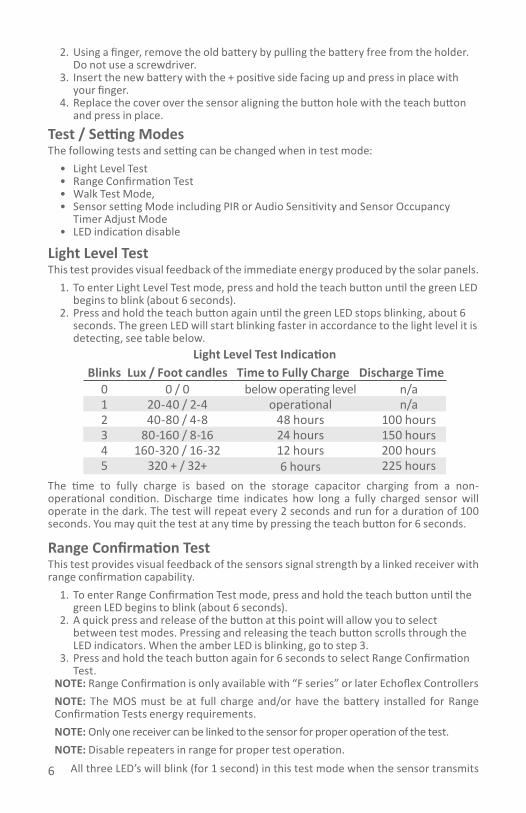
6
2. Using a finger, remove the old battery by pulling the battery free from the holder. Do not use a screwdriver.
3. Insert the new battery with the + positive side facing up and press in place with your finger.
4. Replace the cover over the sensor aligning the button hole with the teach button and press in place.
Test / Setting ModesThe following tests and setting can be changed when in test mode:
• Light Level Test• Range Confirmation Test• Walk Test Mode,• Sensor setting Mode including PIR or Audio Sensitivity and Sensor Occupancy
Timer Adjust Mode• LED indication disable
Light Level Test This test provides visual feedback of the immediate energy produced by the solar panels.
1. To enter Light Level Test mode, press and hold the teach button until the green LED begins to blink (about 6 seconds).
2. Press and hold the teach button again until the green LED stops blinking, about 6 seconds. The green LED will start blinking faster in accordance to the light level it is detecting, see table below.
Light Level Test IndicationBlinks Lux / Foot candles Time to Fully Charge Discharge Time
0 0 / 0 below operating level n/a1 20-40 / 2-4 operational n/a2 40-80 / 4-8 48 hours 100 hours3 80-160 / 8-16 24 hours 150 hours4 160-320 / 16-32 12 hours 200 hours5 320 + / 32+ 6 hours 225 hours
The time to fully charge is based on the storage capacitor charging from a non-operational condition. Discharge time indicates how long a fully charged sensor will operate in the dark. The test will repeat every 2 seconds and run for a duration of 100 seconds. You may quit the test at any time by pressing the teach button for 6 seconds.
Range Confirmation TestThis test provides visual feedback of the sensors signal strength by a linked receiver with range confirmation capability.
1. To enter Range Confirmation Test mode, press and hold the teach button until the green LED begins to blink (about 6 seconds).
2. A quick press and release of the button at this point will allow you to select between test modes. Pressing and releasing the teach button scrolls through the LED indicators. When the amber LED is blinking, go to step 3.
3. Press and hold the teach button again for 6 seconds to select Range Confirmation Test.
NOTE: Range Confirmation is only available with “F series” or later Echoflex ControllersNOTE: The MOS must be at full charge and/or have the battery installed for Range Confirmation Tests energy requirements.NOTE: Only one receiver can be linked to the sensor for proper operation of the test.NOTE: Disable repeaters in range for proper test operation.
All three LED’s will blink (for 1 second) in this test mode when the sensor transmits
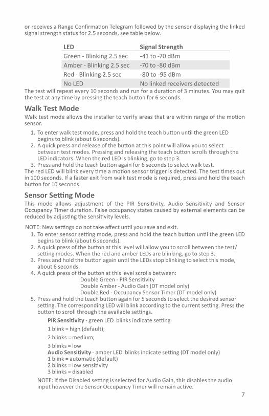
7
or receives a Range Confirmation Telegram followed by the sensor displaying the linked signal strength status for 2.5 seconds, see table below.
LED Signal StrengthGreen - Blinking 2.5 sec -41 to -70 dBm Amber - Blinking 2.5 sec -70 to -80 dBmRed - Blinking 2.5 sec -80 to -95 dBmNo LED No linked receivers detected
The test will repeat every 10 seconds and run for a duration of 3 minutes. You may quit the test at any time by pressing the teach button for 6 seconds.
Walk Test ModeWalk test mode allows the installer to verify areas that are within range of the motion sensor.
1. To enter walk test mode, press and hold the teach button until the green LED begins to blink (about 6 seconds).
2. A quick press and release of the button at this point will allow you to select between test modes. Pressing and releasing the teach button scrolls through the LED indicators. When the red LED is blinking, go to step 3.
3. Press and hold the teach button again for 6 seconds to select walk test. The red LED will blink every time a motion sensor trigger is detected. The test times out in 100 seconds. If a faster exit from walk test mode is required, press and hold the teach button for 10 seconds.
Sensor Setting ModeThis mode allows adjustment of the PIR Sensitivity, Audio Sensitivity and Sensor Occupancy Timer duration. False occupancy states caused by external elements can be reduced by adjusting the sensitivity levels.
NOTE: New settings do not take affect until you save and exit.1. To enter sensor setting mode, press and hold the teach button until the green LED
begins to blink (about 6 seconds).2. A quick press of the button at this level will allow you to scroll between the test/
setting modes. When the red and amber LEDs are blinking, go to step 3. 3. Press and hold the button again until the LEDs stop blinking to select this mode,
about 6 seconds.4. A quick press of the button at this level scrolls between:
Double Green - PIR SensitivityDouble Amber - Audio Gain (DT model only)Double Red - Occupancy Sensor Timer (DT model only)
5. Press and hold the teach button again for 5 seconds to select the desired sensor setting. The corresponding LED will blink according to the current setting. Press the button to scroll through the available settings.
PIR Sensitivity - green LED blinks indicate setting1 blink = high (default); 2 blinks = medium; 3 blinks = lowAudio Sensitivity - amber LED blinks indicate setting (DT model only)1 blink = automatic (default) 2 blinks = low sensitivity 3 blinks = disabled
NOTE: If the Disabled setting is selected for Audio Gain, this disables the audio input however the Sensor Occupancy Timer will remain active.

8
Sensor Occupancy Timer - red LED blinks indicate setting (DT model only)1 blink = disabled 2 blinks = 5 minutes 3 blinks = 10 minutes 4 blinks = 15 minutes5 blinks = 20 minutes (default) 6 blinks = 25 minutes
NOTE: If the Disabled setting is selected for the Sensor Occupancy Timer, the audio will remain active the entire 60 minute duration of the Audio Enabled Timer. Disabling both the Sensor Occupancy Timer and Audio Sensitivity setting will have the sensor behave exactly like the IR model.
6. To save the Sensor setting, press and hold the teach button until all the LEDs double blink. The unit will now be in normal operating mode with the new setting in effect.
LED Indication Enable/DisableNote: the settings do not take effect until you save and exit.
1. Enter Test mode as usual, press and hold the teach button until the green LED begins to blink (about 6 seconds).
2. A quick press and release of the button at this point will allow you to select between test modes. When the green and red LEDs are both blinking simultaneously, go to step 3.
3. Press and hold the teach button again for about 6 seconds until they stop blinking.4. The red LED blinking indicates the motion detection LED is active. The green
LED blinking indicates the LEDs are inactive. Tapping the teach button will toggle between these two states.
5. Save and exit by press and holding the teach button for 5 seconds.
Agency Listings and ComplianceCEC Title 24 CompliantBuilt in an ISO9001 certified facilityFCC Part 15.231 (902 MHz models only)
Contains FCC ID: TCM300UThe enclosed device complies with Part 15 of the FCC Rules.Operation is subject to the following two conditions: (I.) this device may not cause harmful interference and (ii.) this device must accept any interference received, including
interference that may cause undesired operation.IC RSS-210 (902 MHz models only)Contains IC: 5713A-STM300UCE Marking(868 MHz models only)ARIB STDT108 (928MHz models only)Complies with the Japanese radio law and is certified according to ARIB STDT108.This device should not be modified (otherwise the granted designation number will become invalid)
R 206-000372
Copyright 2017 Echoflex Solutions, Inc. | Specifications subject to change without notice. Document # 8DC-5707 | Revision 1.3| 8188M21-5707-1 | Rev D
Echoflex Solutions, Inc. #1, 38924 Queens Way | Squamish | BC | Canada | V8B 0K8
Toll Free: 888-324-6359 | Phone: (778) 733-0111 | Fax: (604) 815-0078Email: [email protected] | www.echoflexsolutions.com

RVS/RCS
This guide covers Resonate Vacancy/Occupancy sensor models, RVS-A-xW, RVS-B-xW, RCS-A-xW and RCS-B-xW. The RCS is identical to the RVS with the addition of a battery to provide power for support of auto-on occupancy sensor applications.The character x in the model number is replaced with U for 902MHz, Y for 868MHz radios, and J for 928MHz radios. The package includes the sensor, installation guide, lens mask sticker and two wire adaptor straps for soft ceiling tile mounting. The cover is removable. Please note: the cover must be fully seated for proper operation.
Resonate Vacancy/ Occupancy Sensor DescriptionThe RVS/RCS (also referred to as the sensor in this guide) is a wireless, energy harvesting sensor that monitors room occupancy state using a passive infrared motion (PIR) detector. The RVS/RCS sensors are intended for indoor use only, mounted on a ceiling at 8-10 feet from the floor.NOTE: The RVS is a solar powered device that absorbs solar energy from artificial or natural light sources. Before assigning the RVS sensor to a receiver or controller, the sensor should be exposed to a good light source for a minimum of 2 minutes.
Resonate Wireless Vacancy/Occupancy Sensor
Installation Guide
echoflexPowered by ETC

2
Sensor OperationThe RVS sensor is powered by solar energy from natural or artificial light sources. The solar energy is transformed into electrical energy which is then used as a power source for the sensor. Powered by two solar cells, the sensor will begin operation without a battery within 2 minutes of being in sufficient light. The sensor will operate with 6 foot candles (65 lux) light energy. The RCS has instantaneous operation (battery powered).
Wireless TelegramsThe motion sensor supports the Occupancy Sensor EnOcean profile A5-07-01. The sensor will transmit occupancy or vacancy depending on the occupancy state of the room. The sensor will broadcast occupancy immediately upon a state change from vacant to occupied. The sensor broadcasts a telegram when movement is detected and repeats occupied telegrams with a minimum 100 second period between subsequent transmissions. After detecting motion, the sensor is shut-down to conserve energy for 100 seconds. When the sensor awakens and further motion is detected, the sensor will transmit an occupied telegram. If no motion is detected within 100 seconds, the sensor transmits a vacancy telegram, 200 seconds total since the previous transmission. The sensor will remain active until the next occupancy state is triggered by motion detection. If the sensor does not detect motion, it resends the vacancy telegram every 1000 seconds.Motion DetectionThe sensors use a PIR sensor element that detects motion by measuring the infrared energy emitted by objects. The sensors are calibrated to detect the temperature range of the human body. The sensor has a lens that breaks the viewing angle of the sensor into zones (movement zones), infrared energy moving in and out of a zone is how the occupied state is defined. The amount of movement that triggers the sensor is dependent upon the density of the zones where the motion takes place. A
Lens B: use for large motion detection or larger rooms.
8ft/2.4m
30ft/9.1m 20ft/6m 10ft/3m 0 10ft/3m 20ft/6m 30ft/9.1m10ft/3m
0
8ft/2.4m
15ft/4.5m 10ft/3m 5ft/1.5m 0 5ft/1.5m 10ft/3m 15ft/4.5m10ft/3m
0
8ft/2.4m
15ft/4.5m 10ft/3m 5ft/1.5m 0 5ft/1.5m 10ft/3m 15ft/4.5m10ft/3m
0
Lens A: use for small motion detection or small rooms.

3
higher density of zones means smaller motion will trigger the sensor. For detection of small motion (typing, drinking from a coffee cup), use the A lens which has more movement zones. Place the sensor close to the location where the motion may occur. The sensor comes with a sticker that can be applied to the lens to mask off areas where motion detection is not desired.An LED under the lens will blink once every 100 seconds when the sensor is detecting motion. Additionally, the LED color indicates the status of the battery when applicable, see the following table.
LED Color Battery StatusRed No battery or weak
Amber 50% discharged
Green Full charge
Mounting the SensorThe mounting location of the sensor is important as this will directly affect the receivers’ reception of the telegrams. Before installing, refer to the sections in the guide detailing the installation of wireless devices, layout tips and test operation modes.NOTE: The sensor cannot detect occupancy through solid objects including items placed by a tenant, such as file cabinets or shelves.NOTE: Do not locate the sensor near forced air vents as hot moving air may cause the sensor to false trigger. Leave at least 4’ (1.2 m) minimum between air vents and the sensor.NOTE: Incandescent lights may cause false trips when turning on.
1. Select a location to mount the sensor on the ceiling by identifying the movement patterns that will be the most common in the space. • For smaller office spaces where hand motion on a desktop is common,
locate the sensor off to one end of the desk, in line with the desk edge or slightly behind so the PIR lens has direct line-of-sight to the keyboard desktop area. Insure that the PIR lens does not have direct line-of-sight out a doorway where walk-by traffic could trigger the sensor. Use the included lens mask stickers to mask off these areas.
• Larger offices where larger body motion is more common, placement of the sensor is less critical.
2. For the best sensor performance, mount the RVS sensor so at least one of the solar cells is facing a light fixture. The sensor will operate in low light levels however, for best performance; a minimum of 6 foot candles must be maintained. If the controlled lights in the space are dimmable either manually or via daylight harvesting, insure the light level at the lowest dimmed level meets this 6 FC requirement. If the light value does not meet this requirement, install a battery.

4
3. Remove the cover by inserting a small screwdriver under the white enclosures lip. Gently twist the screw driver and pull the cover away from the base.
4. Choose a mounting method. The RVS/RCS sensor can be mounted:• With the integrated magnets to a steel T-bar ceiling frame or other
metallic surface by placing the sensor on to the metal rail. • With screws and anchors (not provided) to a wall-board ceiling.
i. Use a pencil to mark the mounting base keyhole locations and remove the sensor.
ii. Using a drill, bore the two holes and insert the anchors.iii. Install the screws, leaving them loose while you place the sensor.iv. Tighten the screws.
• With the provided wire adapter straps to a soft ceiling tile. i. Mark the sensor mounting location on the
ceiling tile with a pencil. Remove the ceiling tile from the T-bar frame.
ii. Insert the soft ceiling tile adapters through the pair of small holes beside both keyholes on the sensors mounting plate.
iii. Poke the adapter tines through the ceiling tile, then bend each tine over in opposite directions for a secure fit.
iv. Replace the ceiling tile.• With double sided tape or Velcro™, not provided. Cut two lengths of
tape and remove the backing. Place on the mounting surface of the sensors back plate, pressing down. Remove the backing from the tapes other side and place the sensor on the ceiling surface, pressing firmly.
5. Refer to the section titled Linking the Sensor to a Receiver.6. Once linking is complete, replace the sensor cover. Ensure the cover is fully
seated. If the cover is not firmly attached, it could obstruct the lens and adversely affect operation.
Lens MaskingLens mask stickers are provided in the packaging for your convenience.
1. As needed, peel off the lens masks to fit the desired area to be blocked.
2. Apply the mask gently to the section of the lens exterior to block the required area from occupancy sensing.
Linking the Sensor to a ReceiverThis process requires the controller or receiver to be mounted, powered and within range of the sensor to be linked.
Lens Mask Applied
Wire Mounts

5
The sensor is a solar powered device that absorbs energy through a solar panel; storing it for use during low light periods. Before assigning the sensor to a receiver/controller, the RVS must be exposed to a good light source for at least 2 minutes.
1. Remove the cover by inserting a small screwdriver under the white enclosures lip. Gently twist the screw driver and pull the cover away from the base.
2. Activate LEARN or LINK mode at the receiver, if necessary refer to the manufacturers documentation.
3. Press the sensors LINK button.4. Deactivate LEARN mode at the receiver.
Installing or Replacing the BatteryThe battery is not required for normal operation when the RVS receives adequate natural or artificial light, minimum 6 foot candles or 65 lux. The RCS model comes with a battery (requires installation).
1. Remove the cover by inserting a small screwdriver under the white enclosures lip. Gently twist the screw driver and pull the cover away from the base.
2. To remove an old battery, use a small screwdriver as a lever and insert under the battery. Gently twist the screwdriver so the battery pops out.
3. Install or replace the battery with a new CR1632 coin cell battery insuring the positive side (+) will be facing up.
4. Place the battery in the holder and press in place with your thumb.
Test Operating ModesTest modes require a battery to be installed. For RVS units, insert a CR1632 battery to run tests. NOTE: An alternative to installing a battery is to use a bright light (hand-held LED light, or Smart Phone) and shine this on the sensor while in test mode. Depending on the light used, this may provide sufficient energy to run the test selected. Do not use this method for Light Level Test, Walk Test Mode or Range Confirmation . Remove the cover for access to the test button.The following 4 tests can be selected when in test mode operation.Light Level Test:
1. To enter Light Level Test mode, press and hold the test button for 6 seconds. The green LED will begin to blink (LEDs are located under the lens).
2. Press the test button again for 6 seconds to select Light Level Test. The green LED will blink in accordance to the light level it is detecting. This will
Battery HolderLink Button

6
change (2 second lag time) if you move the sensor to areas with different light levels. See blink indicator table on the next page.
LIGHT LEVEL TEST TABLEThe green LED will blink according to the energy produced by the solar cell
Blinks Lux Foot Candles Charge Level0 0 0 below operating level1 50-100 4.5 to 9 min. operating level2 100-200 9 to 18 operational3 200-400 18 to 36 operational4 400-800 36 to 72 operational5 800+ 72+ operational
The test will repeat every 2 seconds and run for a duration of 100 seconds. You may quit the test at any time by pressing the Test button for 10 seconds.Range Confirmation Test: provides visual feedback of the sensors signal strength by a linked receiver with range confirmation capability (only “F series” controllers have range confirmation ability). Have only one receiver linked to the sensor for proper operation of the test and disable repeaters in range for proper test operation).The Range Confirmation test requires a battery to be installed.
1. To enter Range Confirmation Test mode, press and hold the test button for 6 seconds. The green LED will begin to blink.
2. A quick press and release of the button at this point will allow you to select between test modes. Pressing and releasing the test button scrolls through the LED indicators. When the amber LED is blinking, go to step 3.
3. Press and hold the test button again for 6 seconds to select Range Confirmation Test.
4. All three LED’s will blink (for 1 second) in this test mode when the sensor transmits or receives a Range Confirmation Telegram followed by the sensor displaying the linked signal strength status for 2.5 seconds.
RANGE CONFIRMATION TEST TABLELED Signal Strength
Green - Blinking 2.5 sec -41 to -70 dBm Amber - Blinking 2.5 sec -70 to -80 dBmRed - Blinking 2.5 sec -80 to -95 dBmNo LED No linked receivers detected
The test will repeat every 4 seconds and run for a duration of 50 seconds. You may quit the test at any time by pressing the test button for 10 seconds.Walk Test Mode: In walk test mode, the red LED will blink on every motion event. This allows an installer to verify the sensor can monitor and detect motion in an area as required.
1. To enter Walk Test mode, press and hold the Test button for 6 seconds. The green LED will begin to blink.

7
2. A quick press and release of the button at this point will allow you to select between test modes. Pressing and releasing the test button scrolls through the LED indicators. When the red LED is blinking, go to step 3.
3. Press and hold the test button again for 6 seconds to select Walk Test mode. The red LED will begin blinking when motion is detected. The test will run for a duration of 100 seconds. You may quit the test at any time by pressing the test button for 10 seconds.
Sensitivity Adjust Mode: The sensitivity feature allows the installer to adjust the sensitivity level. False occupancy states caused by other elements can be reduced by reducing the sensitivity level. The default setting is max. sensitivity. To enter sensitivity adjust mode, press and hold the Test button for 6 seconds. The green LED will begin to blink.
1. A quick press and release of the button at this point will allow you to select between test modes. Pressing and releasing the test button scrolls through the LED indicators. When the red and amber LEDs are blinking simultaneously, go to step 2.
2. Press and hold the test button again for 6 seconds to select PIR sensitivity adjust mode. One of the LEDs will begin blinking based on the selected settings, see the Sensitivity Adjust Table.
3. A press and release of the button will allow you to scroll through the settings as shown in the sensitivity adjust table on page 7.
SENSITIVITY ADJUST TABLE
Setting Indication
High Green LED blinking
Medium Amber LED blinking
Low Red LED blinkingNOTE: The low sensitivity setting is used as the base line for the lens detection ray diagrams found on the data-sheet.
4. To select a setting press and hold the test button for 10 seconds when the desired LED is blinking. To exit without saving, allow the test to time-out in 60 seconds.
Installing Wireless DevicesCareful planning is needed when locating the receivers and transmitters based on the construction materials in the space and possibility of tenant’s furniture disrupting the transmissions.
The occupancy sensor should be installed in the space where the receiver is mounted and connected to the occupancy control equipment. The signal will travel through some material barriers.
Refer to the tables on the next page for range considerations with building materials that reduce the radio signal power.

8
Material AttenuationWood 0 - 10%Plaster 0 - 10%Glass 0 - 10%Brick 5 - 35%MDF 5 - 35%Ferroconcrete 10 - 90%Metal 90 - 100%Aluminum 90 - 100%
Wireless System Layout HintsAvoid locating transmitters and receivers on the same wall.Avoid locating transmitters and receivers where the telegrams must penetrate walls at acute angles. This increases the material the telegram must pass through reducing the signal power. Avoid large metal obstructions as they create radio shadows. Place receivers in alternate locations to avoid the shadow or use repeaters to go around the obstacle.Do not locate receivers close to other high frequency transmitters. Leave at least 3’ between the receiver and any other source of interference including, ballasts, LED drivers, computers, video equipment, Wi-Fi/LAN routers, GSM modems and monitors. Transmitters are not affected by these sources of interference.
echoflexPowered by ETC
Echoflex Solutions, Inc.#1, 38924 Queens Way | Squamish | BC | Canada | V8B 0K8Toll Free: 888-324-6359 | Phone: (778) 733-0111 | Fax: (604) 815-0078Email: [email protected] | www.echoflexsolutions.com
Copyright 2015-2017 Echoflex Solutions, Inc. | Specifications subject to change without notice.Document 8DC-5543 | Revision 1.6| 8188M21-5543-1 | Rev E
Agency Listings and ComplianceCEC Title 24 Compliant
Built in an ISO9001 certified facilityFCC Part 15.231 (902 MHz models only)Contains FCC ID: TCM300UThe enclosed device complies with Part 15 of the FCC Rules.Operation is subject to the following two conditions: (I.) this device may not cause harmful interference and (ii.) this device must accept any interference received, including interference that may cause undesired operation.IC RSS-210 (902 MHz models only)Contains IC: 5713A-STM300U
CE (868 MHz models only)
CE Marking
ARIB STDT108 (928MHz models only)Complies with the Japanese radio law and is certified according to ARIB STDT108.This device should not be modified (otherwise the granted designation number will become invalid)
Material Radio Range-typicalLine of sight: 80’ (24m) corridorsLine of sight: 150’ (46m)open hallsPlasterboard: 80’ (24m) through 3 wallsBrick: 33’ (10m) through 1 wallFerroConcrete: 33’ (10m) through 1 wallCeiling: not recommended
R 206-000372

TAP-21
Task Ambient Photo SensorInstallation Guide
OverviewThis guide covers all models of TAP-21 sensor.The TAP-21 product family includes:
• TAP-21U Photo Sensor with 902 MHz radio• TAP-21Y Photo Sensor with 868 MHz radio• TAP-21J Photo Sensor with 928 MHz radio
The package includes the photo sensor and installation guide.
TAP-21 Sensor DescriptionThe 21 series TAP Task Ambient Photo sensor (also referred to as the sensor in this guide) is a wireless, energy harvesting sensor that monitors light levels within interior spaces and transmits the value to lighting controllers.The sensor measures ambient light in two ranges: 0-510 lux (0 - 50 foot candles) and 0-1024 lux (0 - 100 fc) and is intended for indoor use only.NOTE: The TAP is a solar powered device that absorbs solar energy storing it for use during low light periods. Before assigning the TAP device to a receiver/controller, the device should be exposed to a good light source for a minimum of 5 minutes or install a start assist battery.

2
Page Left Blank Intentionally

3
Sensor OperationThe Task Ambient Photo (TAP) sensor monitors interior light levels. The TAP sensor is powered by solar energy from natural or artificial light sources. The solar energy is transformed into electrical energy which is then stored, providing a continuous power source for the sensor. The sensor will operate even with a brief exposure to light, however for best results the sensor should be mounted in a location with exposure of 3-6 hours of natural or artificial light (250 - 500 lux or 25-50 fc) on a daily basis.The sensor transmits telegrams containing the light level and storage capacitor voltage level. The sensor must be within range of any linked receivers or controllers, installed within 24m (80’) of each other. For applications exceeding 24m (80’) range, telegram repeaters may be needed to extend the reception range.The photo sensor supports the following Sensor profile:EEP A5-06-02: Light Sensor DB_1: 0 lux - 1024 lux DB_2: 0 lux - 512 lux DB_3: Supply Voltage 0…5.1V, linear n=0…255
Daylight HarvestingThe sensor will repeatedly broadcast a telegram on a timer (heart beat timer). The time period adjusts automatically to the ambient light levels and energy charge stored on the radio.
Light Level Timer< 50 lux (5 fc) 100 seconds> 50 lux (5 fc) linear ramp from 60 to 10 seconds (as
device approaches full charge)
Mounting the SensorThe sensor can be mounted on any surface; ceiling, wall, desk, cubicle wall, etc.The mounting location of the sensor is important as this will directly affect the receivers reception of the telegrams. Before installing, refer to the sections in the guide detailing the installation of wireless devices, layout tips and test operation modes.The sensor should be placed so there is direct exposure to a window. The most common mounting location for photo sensors is ceiling mount, centered with the window, about 4’ from the
TIP: To get feedback on the light level where the sensor is mounted, refer to sections “Test Operating Modes” and ‘Light Level Test”.
TIP: For range verification between the sensor and controller, refer to sections “Test Operating Modes” and ‘Installing Wireless Devices”.

4
window. The sensor must be installed in the space where the receiving lighting controller is operating the light fixtures. See the sections on light level test and range confirmation* to aid in optimal placement. * -(requires F series Echoflex controller)The sensor can be mounted using screws (not supplied) through the back plate or using double-sided tape or Velcro™ (not supplied).
Linking a Sensor to a Lighting Controller or ReceiverThis process requires the controller or receiver to be mounted and powered and within range of the sensor to be linked.
1. Activate LEARN or LINK mode at the receiver, if necessary refer to the manufacturers documentation.
2. Tap the sensors TEACH button.3. Deactivate LEARN mode at the receiver.
Selecting the Light Range on the TAP sensor1. Using a fingernail or small flat head screwdriver, pop the rear mounting
plate off the sensor to reveal the range slide switch.2. Slide the switch to the range setting required, 512 lux (50 foot-candles) or
1024 lux (100 foot-candles). The factory default is 512 lux.3. Press the rear mounting plate back into position.
Installing or Replacing the Start Assist BatteryThe battery is not required for normal operation. The battery may be useful for installation purposes (when using the Range Confirmation test and Daylight Harvesting test mode, which depletes the energy stores of the TAP quickly.)
1. Using a fingernail or small flat head screwdriver, pop the rear mounting plate off the sensor.
2. To remove old battery: Using a small flat head screwdriver or pen as a lever, insert pointed end under the battery’s edge and pop out of the holder.
3. Install or replace the battery in the clip with a new CR2032 coin cell battery insuring the battery edge is under the retaining clip and positive side (+) is facing up.
4. Press on the rear mounting plate until it snaps back into position.
Test Operating ModesThe following tests can be selected when in test mode.
1. Light level test2. Range confirmation test3. Daylight harvesting test mode
Light Level Test: This test provides visual feedback of the immediate energy produced by the solar panels.
Teach Button

55
1. To enter Light Level Test mode, press and hold the teach button until the green LED begins to blink (about 6 seconds - LEDs are located on right hand side of the solar panel).
2. Press and hold the teach button again until the green LED stops blinking, about 6 seconds. The green LED will start blinking faster in accordance to the light level it is detecting, see tables below.
At 510 Lux (50 fc) range ( default )
blinks lux foot candles time to fully charge discharge time
0 < 50 <5 below operating level n/a
1 < 142 <14 48.0 hours 67.0 hours
2 < 234 <23 26.5 hours 82.5 hours
3 < 326 <33 18.0 hours 86.75 hours
4 < 418 <42 13.25 hours 88.75 hours
5 >418 >42 11.0 hours 90.0 hours
At 1024 Lux (100 fc) range (switch selectable)
blinks lux foot candles time to fully charge discharge time
0 < 50 <5 below operating level n/a
1 < 244 <24 26.0 hours 82.5 hours
2 < 438 <44 12.5 hours 89.25 hours
3 < 632 <63 10.0 hours 90.75 hours
4 < 826 <83 9.5 hours 91.0 hours
5 > 826 >83 9.0 hours 91.25 hours
The time to fully charge is based on the storage capacitor charging from a non-operational condition. Discharge time indicates how long a fully charged sensor will operate in the dark. The test will repeat every 2 seconds and run for a duration of 100 seconds. You may quit the test at any time by pressing the teach button for 6 seconds.
Range Confirmation Test: This test provides visual feedback of the sensors signal strength by a linked receiver with range confirmation capability.Note:
• Range Confirmation only available with “F series” Echoflex Controllers.• The TAP must be at full charge and/or have the battery installed for Range
Confirmation Tests energy requirements.• Only one receiver can be linked to the sensor for proper operation of the test.• Disable repeaters in range for proper test operation.1. To enter Range Confirmation Test mode, press and hold the teach button
until the green LED begins to blink (about 6 seconds).2. A quick press and release of the button at this point will allow you to select
between test modes. Pressing and releasing the test button scrolls through

6
the LED indicators. When the amber LED is blinking, go to step 3.3. Press and hold the test button again for 6 seconds to select Range
Confirmation Test.All three LED’s will blink on and off (for 1 second) in this test mode, then if the sensor receives a range confirmation telegram, the sensor displays the linked signal strength status for 2.5 seconds, see table below.
LED Signal StrengthGreen - blinking 2.5 sec -41 to -70 dBmAmber - blinking 2.5 sec -70 to -80 dBmRed - blinking 2.5 sec -80 to -95 dBmNo LED No linked receivers detected
The test will repeat every 10 seconds and run for a duration of 50 seconds. You may quit the test at any time by pressing the test button for 6 seconds.
Commissioning Test Mode: This mode accelerates the time period between transmissions of the current light level to every 10 seconds, for a duration of 5 minutes (regardless of amount of energy stored - See “Daylight Harvesting” above). This test requires a start assist battery to be installed for the duration of the test.
1. To enter Commissioning Test Mode, press and hold the teach button until the green LED begins to blink (about 6 seconds).
2. A quick press and release of the button at this point will allow you to select between test modes. Pressing and releasing the test button scrolls through the LED indicators. When the red LED is blinking, go to step 3.
3. Press and hold the test button again for 6 seconds to select Commissioning Test Mode.
You may quit the test at any time by pressing the test button for 6 seconds.

7
Installing Wireless DevicesCareful planning is needed when locating the receivers and transmitters based on the construction materials in the space and possibility of tenant’s furniture disrupting the transmissions.The sensor should be installed in the space where the receiver is mounted. The signal will travel through some material barriers.Refer to the tables below for range considerations with building materials that reduce the radio signal power.
Material Attenuation
Wood 0 - 10%
Plaster 0 - 10%
Glass 0 - 10%
Brick 5 - 35%
MDF 5 - 35%
Ferro concrete 10 - 90%
Metal 90 - 100%
Aluminum 90 - 100%
Wireless System Layout Hints• Avoid locating transmitters and receivers on the same wall.• Avoid locating transmitters and receivers where the telegrams must
penetrate walls at acute angles. This increases the material the telegram must pass through reducing the signal power.
• Avoid large metal obstructions as they create radio shadows. Place receivers in alternate locations to avoid the shadow or use repeaters to go around the obstacle.
• Do not locate receivers close to other high frequency transmitters.
Material Range Typical
Line of sight 80’ (24m) corridorsLine of sight 330’ (100m) open
hallsPlasterboard 80’ (24m) through
3 wallsBrick 33’ (10m) through
1 wallFerro concrete 33’ (10m) through
1 wallCeiling Not Recommended

8
Agency Listings and ComplianceCEC Title 24 CompliantBuilt in an ISO9001 certified facility
FCC Part 15.231 (902 MHz models only)Contains FCC ID: TCM300UThe enclosed device complies with Part 15 of the FCC Rules.Operation is subject to the following two conditions: (I.) this device may not cause harmful interference and (ii.) this device must accept any interference received, including interference that may cause undesired operation.IC RSS-210 (902 MHz models only)Contains IC: 5713A-STM300U
CE (868 MHz models only)CE Marking
ARIB STDT108 (928MHz models only)Complies with the Japanese radio law and is certified according to ARIB STDT108.This device should not be modified (otherwise the granted designation number will become invalid)
Copyright 2013-2017 Echoflex Solutions, Inc. | Specifications subject to change without notice.
Document #8DC-5365 | Revision 1.7 | 8188M21-5365-1 | Rev E
Echoflex Solutions, Inc.#1, 38924 Queens Way | Squamish | BC | Canada | V8B 0K8Toll Free: 888-324-6359 | Phone: (778) 733-0111 | Fax: (604) 815-0078 Email: [email protected] | www.echoflexsolutions.com
R 206-000372

PTM-ETRechoflexPowered by ETC
Wireless SwitchesInstallation Guide
This guide covers all Echoflex switch models.The Echoflex switch models include:PTM265n* Single Decorator style wireless switchPTM265Dn* Dual Decorator style wireless switchETRS1n# Single Resonate Wave style switchETRS2n# Dual Resonate Wave style switchETRH1nW Single Resonate Handheld switch ETRH2nW Dual Resonate Handheld switch PTM265KCAnW Keycard Activated switchThe character n is replaced with U for 902MHz, Y for 868MHz, C for 315MHz and J for 928 MHz radios. The character * is replaced with W for white, B for black, A for almond, V for ivory and R for brown; # available in W - white or B - black onlyThe package includes the switch and installation guide. Note - cover plates for Decorator style switches are not included (can be ordered separately); Resonate Wave switches include double sided tape.

2
Product OverviewThe wireless switches communicate with controllers to activate the controllers internal relay. In most applications, the controller’s relay is connected to a lighting load or circuit and the wireless switch functions as a basic light switch.The switches requires no wiring connections and use no batteries. The kinetic energy of a finger press with the ON or OFF side of the switch generates enough energy to transmit the switch event.Some models have 4 buttons or dual paddles, these operate identically to the single paddle switches. With dual switch models, each switch is separate from the other and can be assigned to the same controller or a different controller.
Mounting the SwitchCareful consideration should be made for locating the controllers and switches based on the construction materials in the space and possibility of tenant’s furniture disrupting the transmissions. The switch should be installed in the space where the controller device is controlling the light fixtures or circuits however the signal will travel through material barriers, refer to the range planning section for more information.All switch models can be mounted on any surface; wall, desk, cubicle wall, etc. with double sided tape (supplied with ETRS models only) or Velcro™ (not supplied). The ON side of the switch should be mounted on the top; The “I” indicates ON (on the front of the Wave and the back of the Decora switches). The “O” indicates OFF. The Resonate Handheld switches have a depression on the ON side of the paddle.Decorator style switches have four (4) mounting holes in the rear mounting plate to attach the switch to a wall surface with screws and wall anchors (not supplied). Install a decorator style faceplate (Leviton 80401 or equivalent-not supplied) over the switch. Test operation of the switch. The paddle should return to a neutral position after release. An audible click is expected.The Wave switches come supplied with double sided tape, you can also remove the front cover of the switch and use the screw guides on the back plate of the switch to mount with screws and wall anchors (not supplied)Hand Held switches have round removable covers on the back (twist off, using small holes for leverage). There are keyholes behind the covers. Use with pre-installed screws (not supplied) - measure 6 cm center to center when placing screws.The Key Card switch is activated with an 85.60 x 53.98 mm (3.37 x 2.125”) card as specified by ISO/IEC7810 - ID-1 (thickness of 0.76 mm (0.03”). For wall mounting, the keycard switch faceplate must be removed before mounting with screws. For proper operation, the provided rear mounting plate must be used when mounting.
1. Remove the faceplate screws and faceplate assembly (includes front cover and insert with key depression tag).
2. There are four (4) mounting holes in the rear mounting plate to attach the switch to a wall surface with screws and wall anchors (not supplied).
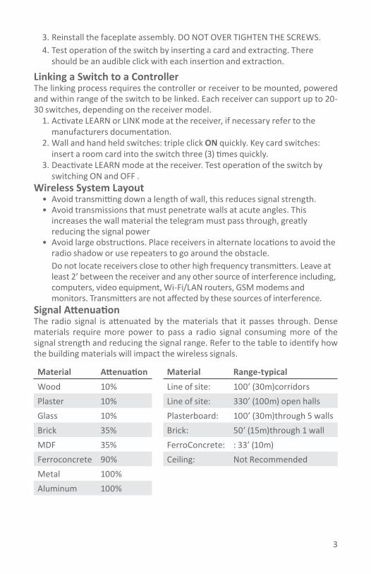
3
3. Reinstall the faceplate assembly. DO NOT OVER TIGHTEN THE SCREWS.4. Test operation of the switch by inserting a card and extracting. There
should be an audible click with each insertion and extraction.
Linking a Switch to a ControllerThe linking process requires the controller or receiver to be mounted, powered and within range of the switch to be linked. Each receiver can support up to 20-30 switches, depending on the receiver model.
1. Activate LEARN or LINK mode at the receiver, if necessary refer to the manufacturers documentation.
2. Wall and hand held switches: triple click ON quickly. Key card switches: insert a room card into the switch three (3) times quickly.
3. Deactivate LEARN mode at the receiver. Test operation of the switch by switching ON and OFF .
Wireless System Layout• Avoid transmitting down a length of wall, this reduces signal strength.• Avoid transmissions that must penetrate walls at acute angles. This
increases the wall material the telegram must pass through, greatly reducing the signal power
• Avoid large obstructions. Place receivers in alternate locations to avoid the radio shadow or use repeaters to go around the obstacle.
Do not locate receivers close to other high frequency transmitters. Leave at least 2’ between the receiver and any other source of interference including, computers, video equipment, Wi-Fi/LAN routers, GSM modems and monitors. Transmitters are not affected by these sources of interference.
Signal AttenuationThe radio signal is attenuated by the materials that it passes through. Dense materials require more power to pass a radio signal consuming more of the signal strength and reducing the signal range. Refer to the table to identify how the building materials will impact the wireless signals.
Material Attenuation Material Range-typicalWood 10% Line of site: 100’ (30m)corridorsPlaster 10% Line of site: 330’ (100m) open hallsGlass 10% Plasterboard: 100’ (30m)through 5 wallsBrick 35% Brick: 50’ (15m)through 1 wallMDF 35% FerroConcrete: : 33’ (10m)Ferroconcrete 90% Ceiling: Not RecommendedMetal 100%Aluminum 100%

4
Echoflex Solutions, Inc.#1, 38924 Queens Way | Squamish | BC | Canada | V8B 0K8Toll Free: 888-324-6359 | Phone: (778) 733-0111 | Fax: (604) 815-0078 Email: [email protected] | www.echoflexsolutions.comechoflex
Powered by ETC
Accessories - also available to order PTM2652GF - 2 gang flush mounting plate for decorator style switches (Leviton 80409 coverplate not supplied)PTM2653GF - 3 gang flush mounting plate for decorator style switches (Leviton 80411 coverplate not supplied)SC01- Antimicrobial Silicone Sleeve, for use with decorator switch onlyFCC Part 15.231 - Remote Control TransmittersThe enclosed device complies with Part 15 of the FCC Rules. Operation is subject to the following two conditions: (I.) this device may not cause harmful interference and(ii.) this device must accept any interference received, including interference that may cause undesired operation.IC RSS-210Devices equipped with 902 MHz radio: Contains FCC ID: SZV-PTM210U Contains IC: 5713A-PTM210UDevices equipped with 868 MHz radio: Contains FCC ID: SZV-PTM200 Contains IC: 5713A-PTM200Devices equipped with 315 MHz radio: Contains FCC ID: SZV-PTM200C Contains IC: 5713A-PTM200C
Devices equipped with 928 MHz radio: Contain PTM 210J which complies with the Japanese radio law and is certified according to ARIB STD-T108
Copyright 2013-2016 Echoflex Solutions, Inc. | Specifications subject to change without notice.Document #8DC-5303 | Revision 2.6 | 8188M21-5303-1 | Rev E