tn1331 introduction technical note
TRANSCRIPT

IntroductionThe mounting instructions provide the main recommendations to handle, assemble and rework the ISOTOP packageappropriately (Figure 1). It is necessary to follow some basic rules for assembly in order to limit thermal and mechanicalstresses and ensure an optimal thermal conduction.
The ISOTOP is a versatile package. The main cooling mechanism is the natural convection through the package heatsink.Indeed, its thick heatsink contributes a lot to thermal dissipation, as well as it ensures the package mechanical robustness.
Although heat extraction can be done by air forced or by heatsink with circulation of coolants, we will focus in this document onthe cooling by conduction method with a fixation to a heatsink with adequate thermal interface.
In addition, the ISOTOP products have a built-in ceramic to guarantee the compliance with insulation requirements as describedin UL1557.
Note: Important, STMicroelectronics strongly recommends the use of the screws delivered together with the product.The use of any other screw is entirely at the user’s own risk and will invalidate the warranty. Check the contentof this technical note for more details.
Figure 1. ISOTOP package dimensions
Assembly recommendations for STMicroelectronics ISOTOP package
TN1331
Technical note
TN1331 - Rev 1 - June 2020For further information contact your local STMicroelectronics sales office.
www.st.com

1 Package description
Table 1. ISOTOP package mechanical data
Ref.
Dimensions
Millimeters
Min. Max.
A 11.80 12.20
A1 8.90 9.10
B 7.80 8.20
C 0.75 0.85
C2 1.95 2.05
D 37.80 38.20
D1 31.50 31.70
E 25.15 25.50
E1 23.85 24.15
E2 24.80
G 14.90 15.10
G1 12.60 12.80
G2 3.50 4.30
F 4.10 4.30
F1 4.60 5.00
H -0.05 0.10
Diam P 4.00 4.30
P1 4.00 4.40
S 30.10 30.30
TN1331Package description
TN1331 - Rev 1 page 2/14
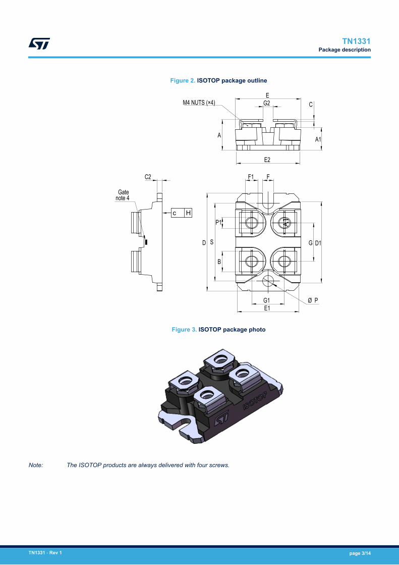
Figure 2. ISOTOP package outline
G1
F1
SD
P1
B
Ø PE1
G D1
F
EG2
A
C
A1
E2
M4 NUTS (×4)
C2
Gatenote 4
c H
Figure 3. ISOTOP package photo
Note: The ISOTOP products are always delivered with four screws.
TN1331Package description
TN1331 - Rev 1 page 3/14

Figure 4. ISOTOP package heatsink screws distance
Table 2. ISOTOP package heatsink specifications
Parameters Values
Flatness (max concavity or convexity between fixing holes) ≤ 20µm (0.78 mils)
Surface finish +/- 1.2 µm ( +/-0.05 mils)
Fixing holes L = 30 mm; +0.4/+1 mm (1.181 inch; +0.016/+0.039 inch)
Figure 5. ISOTOP package heatsink screwing
Table 3. ISOTOP package heatsink screws specifications
Parameters Values
Fixing screw M4 x 0.7 + lock washer
Torque 1.3 +/- 0,2 N.m (7.6 +/- 1.2 LBS.inch)
Rthj-case/heatinkD = M4 x 0.7
< or = 0.005 °CW
TN1331Package description
TN1331 - Rev 1 page 4/14

Table 4. ISOTOP package electrical connectors
Parameters Values
Screws M4 x 0.7 + lock washer
Torque 1.3 +/- 0,2 N.m (7.6 +/- 1.2 LBS.inch)
Pull test ( fast on pins) < or = 80 N
Twist test N/A
Contact area (screw version) 45 mm²
Lead inductance < or = 5 nH
Figure 6. Connectors M4 x 0.7, 8 mm length screws dimensions
Note: Dimensions are given in mm.
Table 5. ISOTOP Packaging details
Parameters Values
Tube 10 pcs + contact set ( screw + washer)
Elementary box ( bulk quantity) 100 units ( 10 tubes)
Ordered quantity Multiples of 10 pcs
TN1331Package description
TN1331 - Rev 1 page 5/14

2 Mounting techniques and recommendations
2.1 Electrical connectors screws and torque recommendation
Additional tests were performed to evaluate the maximum torque that the ISOTOP package may sustain beforemechanical destruction, while assembling the screw, nut and washers on the electrical connectors.The four M4 x 0.7 screws for electrical connection, provided by STMicroelectronics together with the ISOTOPdevices, are specified with a max torque value of 4.5 N.m, in order to prevent the damage of the thread.The nut itself, is guaranteed with a maximum torque value specified at 5 N.m.
Figure 7. ST M4 x 0.7 screw, nut and washer supplied with the ISOTOP package (x4)
• Spring washer outer diameter = 6.95 mm and thickness = 0.8 mm• Plain washer outer diameter = 8 mm and thickness = 0.8 mm
Experiment was led by fastening these M4 x 0.7 mm screws and nuts to the electrical connectors of the ISOTOPpackage. The torque applied was measured by using the adequate Philips screwdriver. Some cracks in themolding compound and lead deformation were observed when applying torque greater than 2.5 N.m.
Figure 8. Pictures of resulting mechanical damage on ISOTOP package
These results indicate that the failure mode is the torsion of the terminal, inducing molding compound breakage.Overtightening the screws may cause other mechanical damages such as ceramic cracks for instance.In order to ensure a correct thermal dissipation (current transfer) and the product electrical functionalities,maximum torque value needs to be respected. Following above destructive tests results, and considering that theweakest point is the resin, defined specification is a max screwing torque of 1.5 N.m.Recommended torque value is 1.3 N.m.
TN1331Mounting techniques and recommendations
TN1331 - Rev 1 page 6/14

The ISOTOP package integrity and performance are conditioned by its mounting on both electrical connectorsand heatsink side.ST Microelectronics strongly recommends to use the 4 screws, nuts and washers supplied together with theISOTOP device for the electrical connectors and to respect the torque values highlighted in this technical note.The usage of any other screw, nut and washer exposes to destructive mechanical stress. This choice is entirely atthe user’s own risk and will invalidate the warranty.Following examples are illustrating failure modes that could occur. This is not an exhaustive description:• If the screw is too long, or if the thread pitch is different from ST screw, the risk is to have the tip of the screw
in contact with the body of the package.• If this contact is too strong, this will generate package body cracks, which may impact product functionality
and reliability.• If the screw used is too short, it may not enter fully in the nut. In such case, there may be risks of damaging
the threads of the screw or the nut, as applied torque may be too high for the portion of thread in contact.
TN1331Electrical connectors screws and torque recommendation
TN1331 - Rev 1 page 7/14

2.2 Heatsink screws and thermal grease recommendations
2.2.1 Heatsink screwsTo fix the ISOTOP package on a chassis or a cooling system, STMicroelectronics recommends SEMS screws(M4, including spring/plain washer) as shown in the Figure 9 below. All mounting screws should have regularwashers and spring washer. It’s important to use the washer to optimize the pressure on heatsink and get auniform contact.
Figure 9. Example of SEMS Nickel plated screw size M4 x 0.7 with spring and plain washer
2.2.2 Thermal conductive greaseTo optimize the heat dissipation, it is necessary to enlarge the contact area as much as possible to minimize thecontact thermal resistance. It is recommended to apply a thermal conductive grease over the contact surfacebetween modules and heat sinks, which is also useful for preventing any corrosion at the contact surface.Of course, the cleanliness of the contact surface must be checked prior to apply the thermal grease. A minimumof 150 μm layer of thermal grease to the module base plate or heat sink is required.While fastening the module, the thermal compound should be observable around the rim of the mounted module.Grease characteristics check over time and across wide operating temperature ranges will help ensuring anoptimized thermal dissipation.A torque screwdriver must be used for fastening operation to the maximum specified torque rating. Exceeding themaximum torque limitation may cause module damage or degradation.
TN1331Heatsink screws and thermal grease recommendations
TN1331 - Rev 1 page 8/14

2.3 ISOTOP package assembly
2.3.1 Bus bar assembly recommendation (with ST screws)STMicroelectronics recommends a bus bar real tolerance of 1.6 mm + / - 0.4 mm. It is important not to place thebus bar between nut and connector because of the risk to damage the package (resin crack).
Figure 10. Bus bar assembly view
Assuming use of ST screws, the recommendation is to place the bus bar on the top, respecting the thicknesstolerances as below:• Max = 2 mm → Risk to damage the thread• Min = 1.2 mm → Risk to damage the package
Figure 11. Bus bar assembly tolerances
TN1331ISOTOP package assembly
TN1331 - Rev 1 page 9/14

2.3.2 Recommendations for heatsink design and assemblyFor the heatsink screw torque, we recommend 1.3 N.m, with 1.5 N.m max. The process window check didn’treveal any failures (package cracks, insulation failures, functional failures) up to 3 N.m. This is for informationpurpose only, as ST customers may use different screws and heatsink.It is required to have a perfect contact between the package bottom side and the heatsink to ensure optimumthermal dissipation. The heatsink or chassis surface should be clean and flat.The flatness recommendation is to get less than 40 microns.The assembly sequence is described as per below instructions:• Fasten temporarily in the sequence 1 → 2• Screw down permanently in the sequence 1 → 2
When using electrical or pneumatic screwdrivers, it is suggested to keep the revolution at 200 rpm max. as therapid impact of the screw may damage the screw or the heatsink. The torque of the electrical or pneumaticautomatic screwdriver must be controlled and adjusted.
Figure 12. Heatsink mounting sequence
A chamfer (90°) should be considered on the heatsink in order to avoid deformation and conserve the flatnessand a good thermal contact.
Figure 13. Heatsink design recommendation
TN1331ISOTOP package assembly
TN1331 - Rev 1 page 10/14

Revision history
Table 6. Document revision history
Date Version Changes
16-Jun-2020 1 Initial release.
TN1331
TN1331 - Rev 1 page 11/14

Contents
1 Package description . . . . . . . . . . . . . . . . . . . . . . . . . . . . . . . . . . . . . . . . . . . . . . . . . . . . . . . . . . . . . . .2
2 Mounting techniques and recommendations . . . . . . . . . . . . . . . . . . . . . . . . . . . . . . . . . . . . . . .6
2.1 Electrical connectors screws and torque recommendation . . . . . . . . . . . . . . . . . . . . . . . . . . . . 6
2.2 Heatsink screws and thermal grease recommendations . . . . . . . . . . . . . . . . . . . . . . . . . . . . . . 8
2.2.1 Heatsink screws . . . . . . . . . . . . . . . . . . . . . . . . . . . . . . . . . . . . . . . . . . . . . . . . . . . . . . . . . 8
2.2.2 Thermal conductive grease . . . . . . . . . . . . . . . . . . . . . . . . . . . . . . . . . . . . . . . . . . . . . . . . . 8
2.3 ISOTOP package assembly. . . . . . . . . . . . . . . . . . . . . . . . . . . . . . . . . . . . . . . . . . . . . . . . . . . . . . 9
2.3.1 Bus bar assembly recommendation (with ST screws) . . . . . . . . . . . . . . . . . . . . . . . . . . . . . 9
2.3.2 Recommendations for heatsink design and assembly. . . . . . . . . . . . . . . . . . . . . . . . . . . . 10
Revision history . . . . . . . . . . . . . . . . . . . . . . . . . . . . . . . . . . . . . . . . . . . . . . . . . . . . . . . . . . . . . . . . . . . . . . .11
Contents . . . . . . . . . . . . . . . . . . . . . . . . . . . . . . . . . . . . . . . . . . . . . . . . . . . . . . . . . . . . . . . . . . . . . . . . . . . . . .12
List of figures. . . . . . . . . . . . . . . . . . . . . . . . . . . . . . . . . . . . . . . . . . . . . . . . . . . . . . . . . . . . . . . . . . . . . . . . . .13
TN1331Contents
TN1331 - Rev 1 page 12/14

List of figuresFigure 1. ISOTOP package dimensions. . . . . . . . . . . . . . . . . . . . . . . . . . . . . . . . . . . . . . . . . . . . . . . . . . . . . . . . . . 1Figure 2. ISOTOP package outline . . . . . . . . . . . . . . . . . . . . . . . . . . . . . . . . . . . . . . . . . . . . . . . . . . . . . . . . . . . . . 3Figure 3. ISOTOP package photo. . . . . . . . . . . . . . . . . . . . . . . . . . . . . . . . . . . . . . . . . . . . . . . . . . . . . . . . . . . . . . 3Figure 4. ISOTOP package heatsink screws distance . . . . . . . . . . . . . . . . . . . . . . . . . . . . . . . . . . . . . . . . . . . . . . . . 4Figure 5. ISOTOP package heatsink screwing . . . . . . . . . . . . . . . . . . . . . . . . . . . . . . . . . . . . . . . . . . . . . . . . . . . . . 4Figure 6. Connectors M4 x 0.7, 8 mm length screws dimensions . . . . . . . . . . . . . . . . . . . . . . . . . . . . . . . . . . . . . . . . 5Figure 7. ST M4 x 0.7 screw, nut and washer supplied with the ISOTOP package (x4) . . . . . . . . . . . . . . . . . . . . . . . . . 6Figure 8. Pictures of resulting mechanical damage on ISOTOP package . . . . . . . . . . . . . . . . . . . . . . . . . . . . . . . . . . 6Figure 9. Example of SEMS Nickel plated screw size M4 x 0.7 with spring and plain washer . . . . . . . . . . . . . . . . . . . . . 8Figure 10. Bus bar assembly view . . . . . . . . . . . . . . . . . . . . . . . . . . . . . . . . . . . . . . . . . . . . . . . . . . . . . . . . . . . . . . 9Figure 11. Bus bar assembly tolerances . . . . . . . . . . . . . . . . . . . . . . . . . . . . . . . . . . . . . . . . . . . . . . . . . . . . . . . . . . 9Figure 12. Heatsink mounting sequence . . . . . . . . . . . . . . . . . . . . . . . . . . . . . . . . . . . . . . . . . . . . . . . . . . . . . . . . . 10Figure 13. Heatsink design recommendation . . . . . . . . . . . . . . . . . . . . . . . . . . . . . . . . . . . . . . . . . . . . . . . . . . . . . . 10
TN1331List of figures
TN1331 - Rev 1 page 13/14

IMPORTANT NOTICE – PLEASE READ CAREFULLY
STMicroelectronics NV and its subsidiaries (“ST”) reserve the right to make changes, corrections, enhancements, modifications, and improvements to STproducts and/or to this document at any time without notice. Purchasers should obtain the latest relevant information on ST products before placing orders. STproducts are sold pursuant to ST’s terms and conditions of sale in place at the time of order acknowledgement.
Purchasers are solely responsible for the choice, selection, and use of ST products and ST assumes no liability for application assistance or the design ofPurchasers’ products.
No license, express or implied, to any intellectual property right is granted by ST herein.
Resale of ST products with provisions different from the information set forth herein shall void any warranty granted by ST for such product.
ST and the ST logo are trademarks of ST. For additional information about ST trademarks, please refer to www.st.com/trademarks. All other product or servicenames are the property of their respective owners.
Information in this document supersedes and replaces information previously supplied in any prior versions of this document.
© 2020 STMicroelectronics – All rights reserved
TN1331
TN1331 - Rev 1 page 14/14