tmg j000 - signalling safeworking procedures - manual j · 2019-05-21 · minimum requirements to...
TRANSCRIPT
TN 096: 2014
A3907827 Asset Standards Authority © State of NSW through Transport for NSW Page 1 of 2
For queries regarding this document [email protected]
www.asa.transport.nsw.gov.au
Technical Note TN 096: 2014
Issued date 09 December 2014 Effective date 01 April 2015
Subject: Withdrawal of TMG J000 Signalling Safeworking Procedures (Manual J)
Asset Standards Authority (ASA) publications include legacy RailCorp engineering standards
that are applicable to TfNSW rail assets. These were transitioned to ASA as part of the rail
reform and include TMG J000 Signalling Safeworking Procedures, which was published as an
interim arrangement.
It has since been agreed by the relevant parties that signalling safeworking procedures, specific
to domain environments, be owned and published by operators/maintainers in meeting their
obligations to the rail regulator, as rail infrastructure managers.
To ensure a consistent and coherent application of signalling safeworking across the TfNSW rail
network, ASA has produced a standard that sets out the mandatory requirements to be included
in operator/maintainer signalling safeworking procedures. Accordingly, ASA standard
T HR SC 02000 ST Mandatory Requirements for Signalling Safeworking Procedure sets out the
minimum requirements to be included in the operator/maintainer signalling safeworking
procedures and specifies the authority levels of signalling personnel when working on the
operational or potentially operational signalling system.
T HR SC 02000 ST will be effective from 01 April 2015 at which time TMG J000 Signalling
Safeworking Procedures – Manual J will be withdrawn. This requires that from the effective
date, all applicable operator/maintainer organisations within the TfNSW network will have
applied their own signalling safeworking procedures compliant with T HR SC 02000 ST.

TN 096: 2014
Page 2 of 2
Authorisation
Technical content prepared by
Checked and approved by
Interdisciplinary coordination checked by
Authorised for release
Signature
Name Paul Zammit Peter McGregor David Spiteri Graham Bradshaw
Position Principal Engineer Signals Assurance
Lead Engineer Signals and Control Systems
Chief Engineer Principal Manager Network Standards & Services
Asset Standards Authority A3907827 © State of NSW through Transport for NSW
TN 002 : 2014
3115181_2.DOC Asset Standards Authority © State of NSW through Transport for NSW Page 1 of 1
For queries regarding this document
[email protected] www.asa.transport.nsw.gov.au
Technical Note TN 002 : 2014 Issued date 24 January 2014 Effective from 01 March 2014 Subject: Replacement of RailCorp Waiver Processes
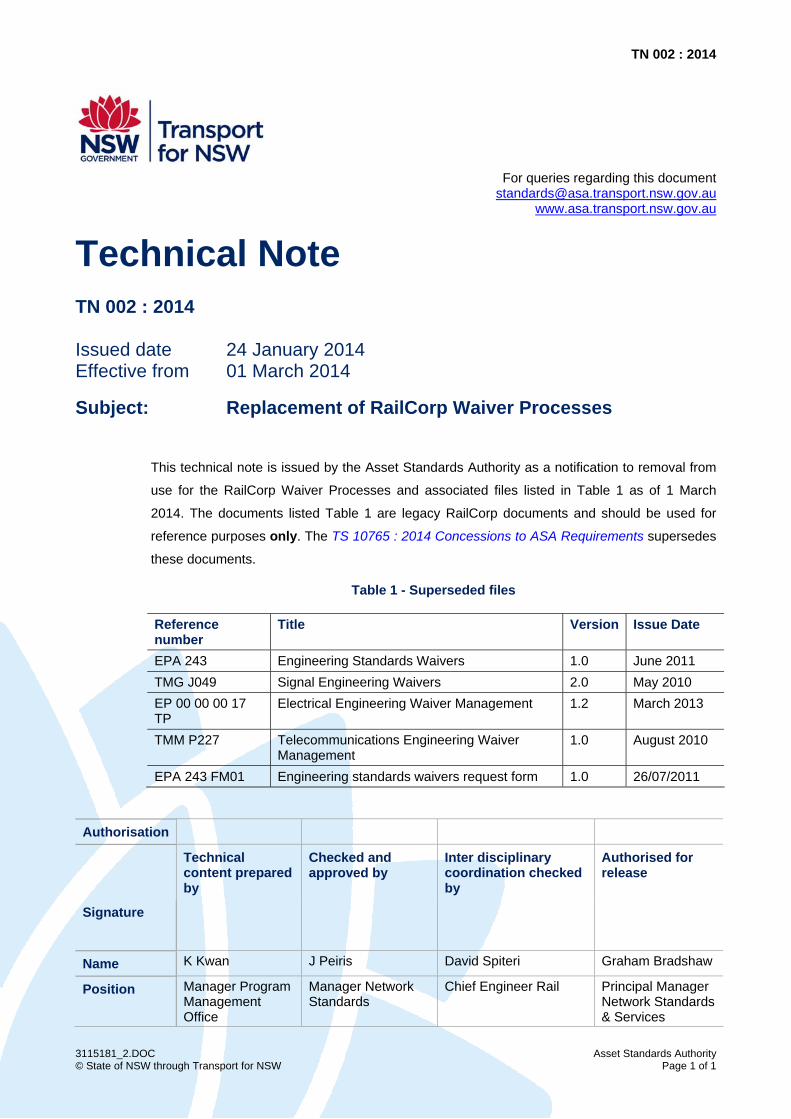
This technical note is issued by the Asset Standards Authority as a notification to removal from
use for the RailCorp Waiver Processes and associated files listed in Table 1 as of 1 March
2014. The documents listed Table 1 are legacy RailCorp documents and should be used for
reference purposes only. The TS 10765 : 2014 Concessions to ASA Requirements supersedes
these documents.
Table 1 - Superseded files
Reference number
Title Version Issue Date
EPA 243 Engineering Standards Waivers 1.0 June 2011 TMG J049 Signal Engineering Waivers 2.0 May 2010 EP 00 00 00 17 TP
Electrical Engineering Waiver Management 1.2 March 2013
TMM P227 Telecommunications Engineering Waiver Management
1.0 August 2010
EPA 243 FM01 Engineering standards waivers request form 1.0 26/07/2011
Authorisation
Technical content prepared by
Checked and approved by
Inter disciplinary coordination checked by
Authorised for release
Signature
Name K Kwan J Peiris David Spiteri Graham Bradshaw
Position Manager Program Management Office
Manager Network Standards
Chief Engineer Rail Principal Manager Network Standards & Services

TN 001 : 2014
tn-001.DOC Asset Standards Authority © State of NSW through Transport for NSW Page 1 of 1
For queries regarding this document [email protected]
www.asa.transport.nsw.gov.au
Technical Note TN 001 : 2014
Issued date 22 January 2014 Effective dates 22 January 2014 to 21 January 2015
Subject: Replacement of TMG J025 V2.4
This technical note is issued by the Asset Standards Authority to advise interim amendments to
RailCorp Signalling Safeworking Procedures Manual J issued in June 2013 pending its full
revision.
Section TMG J025 Track Circuits Version 2.4 of Manual J is superseded by TMG J025 Track
Circuits Version 2.5; January 2014 embedded in TMG J000 Signalling Safeworking Procedures
Manual J.
The Index page 2 of TMG J000 Signalling Safeworking Procedures Manual J; issued
June 2013, has been updated.
Authorisation
Technical content prepared by
Checked and approved by
Inter disciplinary coordination checked by
Authorised for release
Signature
Name Paul Zammit Peter McGregor David Spiteri Graham Bradshaw
Position Principal Engineer Signals Assurance
Lead Signals and Control Systems Engineer
Chief Engineer Rail
Principal Manager Network Standards & Services
Engineering Manual Signals Signalling Safeworking Procedures: Manual J
TMG J000
Engi
neer
ing
Man
ual
SIGNALLING SAFEWORKING PROCEDURES
MANUAL J
Issued June 2013
Owner: Chief Engineer Signals and Control Systems
Approved by:
Warwick Allison Chief Engineer Signals and Control Systems
Authorised by:
Paul Zammit Principal Engineer Signal Assurance
Disclaimer This document was prepared for use on the RailCorp Network only. RailCorp makes no warranties, express or implied, that compliance with the contents of this document shall be sufficient to ensure safe systems or work or operation. It is the document user’s sole responsibility to ensure that the copy of the document it is viewing is the current version of the document as in use by RailCorp. RailCorp accepts no liability whatsoever in relation to the use of this document by any party, and RailCorp excludes any liability which arises in any manner by the use of this document. Copyright The information in this document is protected by Copyright and no part of this document may be reproduced, altered, stored or transmitted by any person without the prior consent of RailCorp.
UNCONTROLLED WHEN PRINTED Page 1 of 4 Sup
erse
ded
by T
HR
SC
020
00 S
T
RailCorp Engineering Manual — Signals — Signalling Safeworking Procedures: Manual J Manual J TMG J000
© RailCorp Page 2 of 4 Issued June 2013 UNCONTROLLED WHEN PRINTED
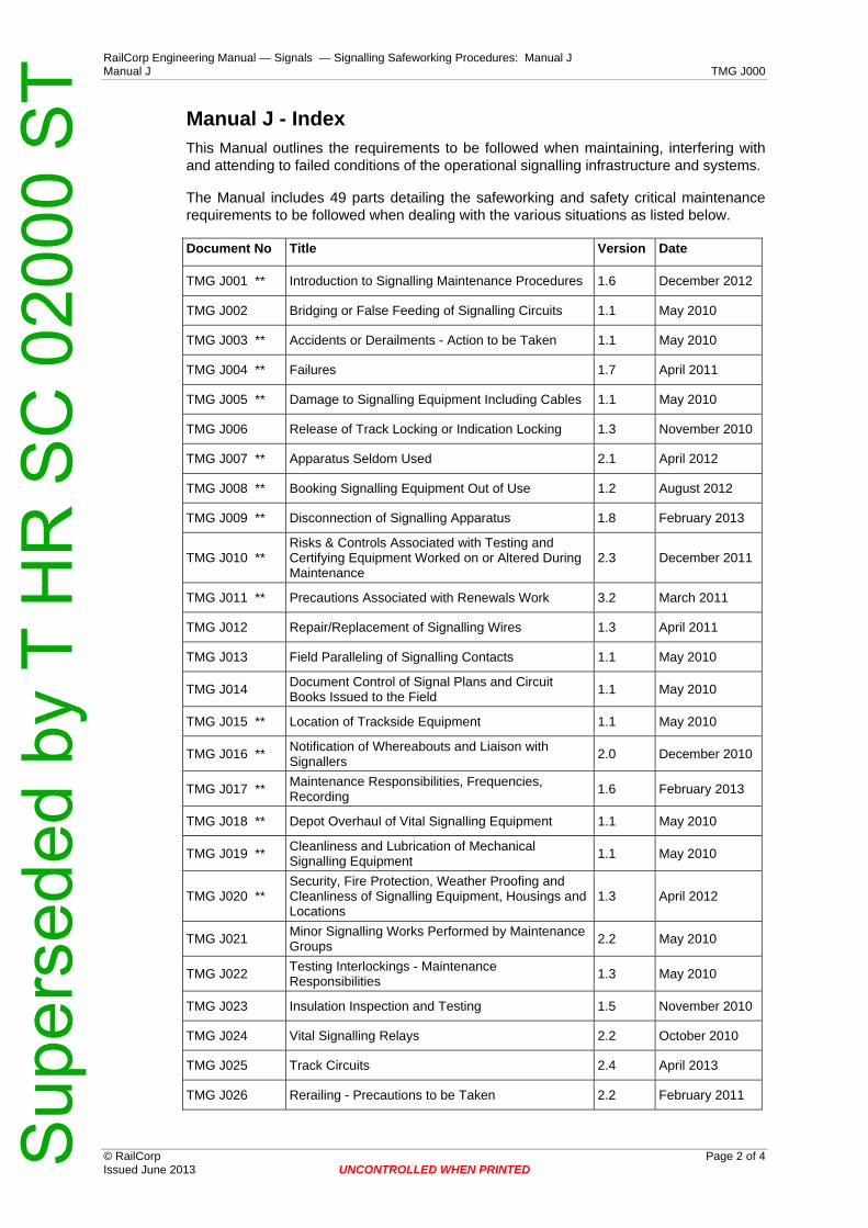
Manual J - Index This Manual outlines the requirements to be followed when maintaining, interfering with and attending to failed conditions of the operational signalling infrastructure and systems.
The Manual includes 49 parts detailing the safeworking and safety critical maintenance requirements to be followed when dealing with the various situations as listed below.
Document No Title Version Date
TMG J001 ** Introduction to Signalling Maintenance Procedures 1.6 December 2012
TMG J002 Bridging or False Feeding of Signalling Circuits 1.1 May 2010
TMG J003 ** Accidents or Derailments - Action to be Taken 1.1 May 2010
TMG J004 ** Failures 1.7 April 2011
TMG J005 ** Damage to Signalling Equipment Including Cables 1.1 May 2010
TMG J006 Release of Track Locking or Indication Locking 1.3 November 2010
TMG J007 ** Apparatus Seldom Used 2.1 April 2012
TMG J008 ** Booking Signalling Equipment Out of Use 1.2 August 2012
TMG J009 ** Disconnection of Signalling Apparatus 1.8 February 2013
TMG J010 ** Risks & Controls Associated with Testing and Certifying Equipment Worked on or Altered During Maintenance
2.3 December 2011
TMG J011 ** Precautions Associated with Renewals Work 3.2 March 2011
TMG J012 Repair/Replacement of Signalling Wires 1.3 April 2011
TMG J013 Field Paralleling of Signalling Contacts 1.1 May 2010
TMG J014 Document Control of Signal Plans and Circuit Books Issued to the Field 1.1 May 2010
TMG J015 ** Location of Trackside Equipment 1.1 May 2010
TMG J016 ** Notification of Whereabouts and Liaison with Signallers 2.0 December 2010
TMG J017 ** Maintenance Responsibilities, Frequencies, Recording 1.6 February 2013
TMG J018 ** Depot Overhaul of Vital Signalling Equipment 1.1 May 2010
TMG J019 ** Cleanliness and Lubrication of Mechanical Signalling Equipment 1.1 May 2010
TMG J020 ** Security, Fire Protection, Weather Proofing and Cleanliness of Signalling Equipment, Housings and Locations
1.3 April 2012
TMG J021 Minor Signalling Works Performed by Maintenance Groups 2.2 May 2010
TMG J022 Testing Interlockings - Maintenance Responsibilities 1.3 May 2010
TMG J023 Insulation Inspection and Testing 1.5 November 2010
TMG J024 Vital Signalling Relays 2.2 October 2010
TMG J025 Track Circuits 2.4 April 2013
TMG J026 Rerailing - Precautions to be Taken 2.2 February 2011
Sup
erse
ded
by T
HR
SC
020
00 S
T
RailCorp Engineering Manual — Signals — Signalling Safeworking Procedures: Manual J Manual J TMG J000
© RailCorp Page 3 of 4 Issued June 2013 UNCONTROLLED WHEN PRINTED
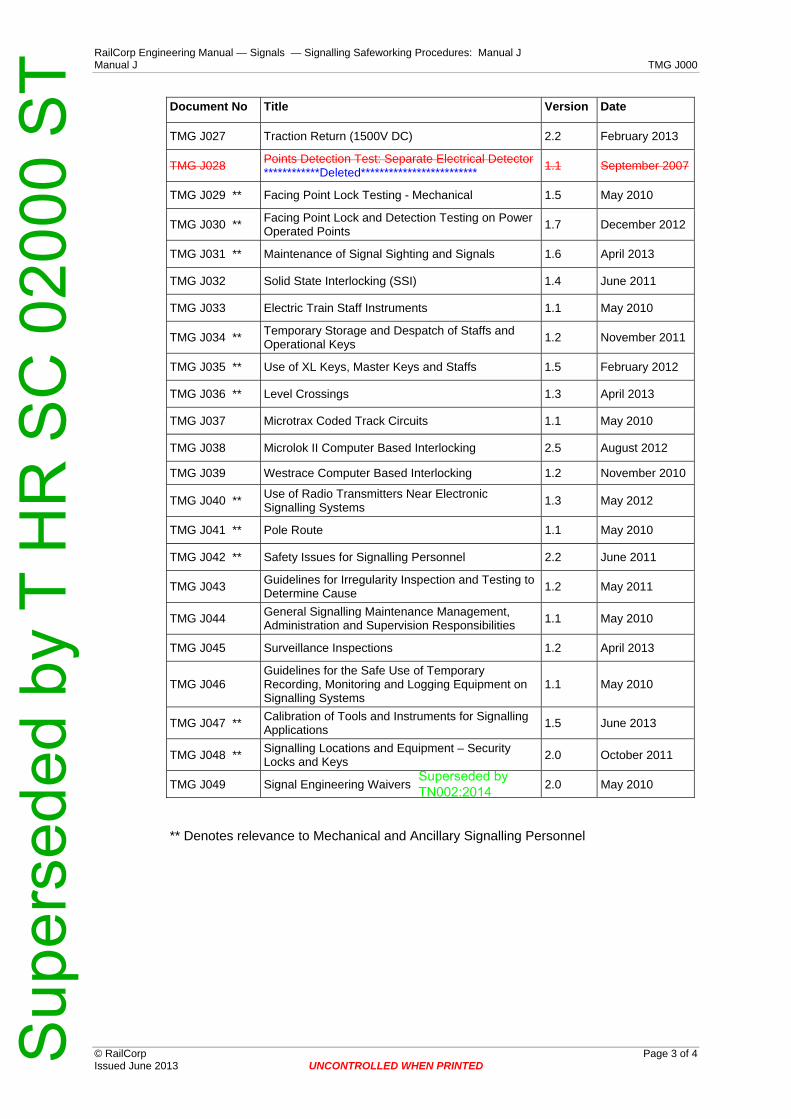
Date Document No Title Version
TMG J027 Traction Return (1500V DC) 2.2 February 2013
TMG J028 Points Detection Test: Separate Electrical Detector************Deleted************************* 1.1 September 2007
TMG J029 ** Facing Point Lock Testing - Mechanical 1.5 May 2010
TMG J030 ** Facing Point Lock and Detection Testing on Power Operated Points 1.7 December 2012
TMG J031 ** Maintenance of Signal Sighting and Signals 1.6 April 2013
TMG J032 Solid State Interlocking (SSI) 1.4 June 2011
TMG J033 Electric Train Staff Instruments 1.1 May 2010
TMG J034 ** Temporary Storage and Despatch of Staffs and Operational Keys 1.2 November 2011
TMG J035 ** Use of XL Keys, Master Keys and Staffs 1.5 February 2012
TMG J036 ** Level Crossings 1.3 April 2013
TMG J037 Microtrax Coded Track Circuits 1.1 May 2010
TMG J038 Microlok II Computer Based Interlocking 2.5 August 2012
TMG J039 Westrace Computer Based Interlocking 1.2 November 2010
TMG J040 ** Use of Radio Transmitters Near Electronic Signalling Systems 1.3 May 2012
TMG J041 ** Pole Route 1.1 May 2010
TMG J042 ** Safety Issues for Signalling Personnel 2.2 June 2011
TMG J043 Guidelines for Irregularity Inspection and Testing to Determine Cause 1.2 May 2011
TMG J044 General Signalling Maintenance Management, Administration and Supervision Responsibilities 1.1 May 2010
TMG J045 Surveillance Inspections 1.2 April 2013
TMG J046 Guidelines for the Safe Use of Temporary Recording, Monitoring and Logging Equipment on Signalling Systems
1.1 May 2010
TMG J047 ** Calibration of Tools and Instruments for Signalling Applications 1.5 June 2013
TMG J048 ** Signalling Locations and Equipment – Security Locks and Keys 2.0 October 2011
TMG J049 Signal Engineering Waivers 2.0 May 2010
** Denotes relevance to Mechanical and Ancillary Signalling Personnel
Superseded by TN002:2014
Sup
erse
ded
by T
HR
SC
020
00 S
T

RailCorp Engineering Manual — Signals — Signalling Safeworking Procedures: Manual J Manual J TMG J000
© RailCorp Page 4 of 4 Issued June 2013 UNCONTROLLED WHEN PRINTED
This page has been intentionally left blank
Sup
erse
ded
by T
HR
SC
020
00 S
T

RailCorp Engineering Manual — Signals — Signalling Safeworking Procedures: Manual J Introduction to Signalling Safeworking Procedures TMG J001
© RailCorp Page 1 of 6 Issued December 2012 UNCONTROLLED WHEN PRINTED Version 1.6
TMG J001
INTRODUCTION TO SIGNALLING SAFEWORKING PROCEDURES
Version 1.6
Issued December 2012
Document control
Version Date Summary of change
Replaced SC 00 52 00 01 SI Introduction to Signalling Maintenance Procedures
1.0 September 2005 RailCorp format 1.1 8 April 2008 Section 1.3 – Item 18 - Correction to title of Chief Engineer Signals 1.2 August 2009 Update in line with new SPG 0711.9 implementation
Clarified definition of Signalling Maintainer in 1.2.2 Added/updated items in Basic Requirements in 1.3
1.3 November 2009 Remove requirement for keeping a copy of J Manual Sections 1.1 – 1.4 revised Added "suitably licensed" to credentials Title name change
1.4 May 2010 Application of TMA 400 format 1.5 December 2011 Reference Authorised Person in document and better define
Signalling Maintainer. Added reference for definition of Commissioning Engineer. Included Like for Like provisions in section 1.5(r).
1.6 December 2012 Clarify the responsibility of Signal Maintenance Engineers & delegates.
Contents 1 Introduction .............................................................................................................................2
1.1 Purpose .....................................................................................................................2 1.2 Requirements ............................................................................................................2 1.3 Network Rules and Procedures & Signalling Safeworking Procedures ....................2 1.4 Position Roles and Responsibilities...........................................................................2
1.4.1 Maintenance Signal Engineer ....................................................................2 1.4.2 Commissioning Engineer ...........................................................................3 1.4.3 Signalling Maintainer ..................................................................................3 1.4.4 Authorised Person......................................................................................3
1.5 Basic Signalling Safeworking Requirements.............................................................3
Sup
erse
ded
by T
HR
SC
020
00 S
T

RailCorp Engineering Manual — Signals — Signalling Safeworking Procedures: Manual J Introduction to Signalling Safeworking Procedures TMG J001
© RailCorp Page 2 of 6 Issued December 2012 UNCONTROLLED WHEN PRINTED Version 1.6
1 Introduction 1.1 Purpose
The purpose of the Signalling Safeworking Procedures is to bring to the attention of signalling personnel, engaged in work that affects (or could affect) installed/operational signalling apparatus, the essential requirements, standard practices and instructions, that ensure the signalling system performs reliably and with integrity, thus allowing rail traffic to operate safely on the network and without delay.
1.2 Requirements
Signalling personnel shall have access to and familiarise themselves with the Signalling Safeworking Procedures, including any associated or referenced standards. They shall keep up to date with any changes that apply and develop an understanding of the principle intention of the changes.
Users of the Signalling Safeworking Procedures shall promptly bring to the attention of the Chief Engineer Signals & Control Systems (or delegated officer) for determination of any perceived omission, error, ambiguity, inconsistency or lack of clarity with the procedures as well as suggestions for improvement.
1.3 Network Rules and Procedures & Signalling Safeworking Procedures
The Network Rules and Procedures direct how work affecting the operation of signalling shall be safely carried out. The Signalling Safeworking Procedures shall be read and carried out in conjunction with the Network Rules and Procedures which they are intended to supplement, and in no way supersede.
Signalling personnel shall comply with the Network Rules and Procedures and the Signalling Safeworking Procedures.
1.4 Position Roles and Responsibilities
For the purpose of these procedures, titles such as Signal Engineer and Signalling Maintainer (including Signal Electrician, Mechanical Maintainer, Linesman, Maintenance Supervisor, Air-line Fitter, Rail Bond Welder, Cable Jointer, etc), unless otherwise stipulated, shall mean a person trained, qualified, competent and suitably licensed to perform the specific task referred to in the context of the procedures.
Persons who are not competent and suitably licensed must not interfere with operational signalling equipment. Additionally, persons who are not licensed or authorised shall not perform signalling work or enter a signalling location unless closely supervised.
Where individual responsibility is not explicit in the text of the Signalling Safeworking Procedures, signalling personnel shall contact a relevant, licensed Signal Engineer for clarification.
A full listing of licensed signalling and authorised personnel is available in TMG A1415 Signalling Personnel - Authorisation Status & Licensing Boards.
1.4.1 Maintenance Signal Engineer
The Maintenance Signal Engineer is the senior Signal Engineer responsible for the safety and integrity of the signalling infrastructure on their region/district, and unless otherwise stipulated, may delegate the various tasks specified to them in these procedures to
Sup
erse
ded
by T
HR
SC
020
00 S
T

RailCorp Engineering Manual — Signals — Signalling Safeworking Procedures: Manual J Introduction to Signalling Safeworking Procedures TMG J001
© RailCorp Page 3 of 6 Issued December 2012 UNCONTROLLED WHEN PRINTED Version 1.6
another licensed Signal Engineer on their region/district. However, in doing so, does not dispense with the responsibility. A document stating the responsibilities delegated to others in accordance with these Signalling Safeworking Procedures shall be kept by the Maintenance Signal Engineer to ensure all persons clearly understand their delegated responsibilities.
Maintenance Signal Engineers are still ultimately accountable for ensuring the task/s are appropriately handled and completed safely and in accordance with these procedures.
1.4.2 Commissioning Engineer
As defined in SPG 0711.1 Inspection & Testing of Signalling – Roles, Responsibilities and Authorities.
1.4.3 Signalling Maintainer
The Signalling Maintainer is a licensed person who is required, as part of their duties in accordance with their Certificate of Competency and Permit to Work, to interfere with the installed/operational signalling system as detailed throughout these procedures.
There are different licensing levels for Signalling Maintainers; they include Signal Electrician, Signals Mechanical and Signals Ancillary. These persons shall be assessed as competent by an approved process for the intended work and shall only perform signalling work within their delegated area of authority. The different licensing levels are described in detail in TMG A1412 Signalling Personnel – Authorisations & Licensing.
1.4.4 Authorised Person
An Authorised Person is a person who has been assessed as competent by an approved process to perform defined activities (generally signalling activities) in signalling equipment enclosures or on signalling equipment within their delegated area of authority, where the work will not interfere with operational signalling equipment.
There are different authorisation levels for Authorised Person, these are described in detail in TMG A1412 Signalling Personnel – Authorisations & Licensing.
1.5 Basic Signalling Safeworking Requirements
Some basic requirements relating to maintaining the signalling system are set out below. They are described in detail in the procedures in the following sections of the Signalling Safeworking Procedures.
a) Signalling maintenance shall be managed and performed to meet the relevant requirements of Australian Standards for Railway Safety Management AS4292 Part 1 General and Interstate Requirements and Part 4 Signalling and Telecommunications Equipment and Systems.
b) The installed signalling system and its components are to be maintained to prevent signalling system failures and associated train delays, and to ensure the safety provided by the system is maintained throughout its operational life.
c) Failed signalling equipment is to be attended to and restored for operational use without undue delay.
d) Details of signalling maintenance, signalling failures and irregularities are to be recorded and analysed to determine any corrective action necessary and to ensure equipment/system safety and reliability levels are maintained.
Sup
erse
ded
by T
HR
SC
020
00 S
T

RailCorp Engineering Manual — Signals — Signalling Safeworking Procedures: Manual J Introduction to Signalling Safeworking Procedures TMG J001
© RailCorp Page 4 of 6 Issued December 2012 UNCONTROLLED WHEN PRINTED Version 1.6
e) Only suitably licensed signalling persons, using authorised practices, test equipment, tools, materials and equipment are to maintain the operational signalling system or its components. Test equipment and tools in use are to be in proper working order.
f) Persons who are not suitably licensed or authorised shall not have access to enclosures housing vital signalling equipment except under the supervision of a suitably licensed or suitably authorised person, or as permitted in accordance with stipulated conditions.
g) Only suitably licensed persons, or persons directly supervised by suitably licensed persons, are to disconnect or connect to the operational signalling system equipment and circuits.
h) The movement of trains must be adequately protected when any maintenance action or other interference impairs, or could impair the protection provided by the signalling system or could affect the safety of the line.
i) Where the interlocking is disarranged or vital signalling equipment is disconnected from the interlocking, or is disassembled, or has safety critical adjustments altered, then its safe operation must be certified fit before restoring it for operational use.
j) Signalling equipment which has failed in an unsafe manner must be taken out of service and the train movements affected must be immediately protected.
The irregularity must be fully investigated, the defect rectified or addressed, and the equipment must be tested and certified as operating safely before being restored for operational use.
Subject to the former, should signalling apparatus be defective in any manner which potentially might endanger traffic operations, it is to be immediately repaired or replaced if practical. If it cannot be immediately repaired or replaced, its operation must be discontinued and traffic operations must be protected. Details must be immediately reported to controlling officers.
k) When any function of the signalling system affecting traffic operations is to be taken out of service, the system operator of the affected area is to be advised.
l) Release of track locking or signal indication locking must only be given as prescribed.
m) Temporary bridging of contacts of vital signalling control devices must only be carried out as prescribed.
n) Trainstops must only be manually suppressed for train services as prescribed.
o) Where locking facilities are normally provided, the signalling equipment is to be kept locked to prevent unauthorised interference.
p) Alterations or additions to the configuration of the signalling system or its components must not be made unless properly authorised.
q) Whenever the signalling system requires additions or modifications, then the requirements of Standard Specification SPG 0711 and these procedures shall be observed.
r) Prior approval of the Chief Engineer Signals & Control Systems is required before any aspect of the operational signalling system, vital or non-vital, that could affect the safety and/or reliability of the system, is introduced or altered.
Sup
erse
ded
by T
HR
SC
020
00 S
T
RailCorp Engineering Manual — Signals — Signalling Safeworking Procedures: Manual J Introduction to Signalling Safeworking Procedures TMG J001
© RailCorp Page 5 of 6 Issued December 2012 UNCONTROLLED WHEN PRINTED Version 1.6
This requirement includes, the application of experimental, new or modifications to design, signalling systems, signal equipment, train control systems, automatic train protection equipment, standards for manufacture, construction, operations, maintenance, disposal and procedures and practices, including practices that were not specifically covered by documented standards but for which a documented standard should apply.
Prior approval of the Chief Engineer Signals & Control Systems is not required for Like for Like Renewals where the equipment is replaced with an exactly identical item. Maintenance Signal Engineers are delegated to make determinations whether renewal work can be treated as Like for Like where items are not exactly identical. Like for Like Renewal determinations and conducted work shall be in accordance with TMG J011 Precautions Associated with Renewals Work and SPG 0711.9 Like for Like Renewals Procedures.
s) Signalling plans, diagrams and circuit books for operating and maintenance use must be available to those who need them to carry out their duties and be maintained up to date.
t) Off-site repair and overhaul of vital signalling equipment shall be authorised and controlled to ensure the equipment is restored to the required specification and standard before being re-used.
u) Temporary repairs of vital signalling equipment shall be done to an acceptable and safe standard, and procedures shall ensure the temporary repairs are brought up to the permanent standard before they present an unacceptable risk to the safe and reliable operation of the signalling system.
v) Malicious damage or interference to vital signalling equipment or circuits must be reported promptly to controlling officers.
w) Test equipment for measuring signalling system safety and reliability parameters shall be calibrated where required to verify acceptance/rejection criteria.
x) Prior approval of the Chief Engineer Signals & Control Systems is required before the engagement of contractors in senior signalling roles within RailCorp, for example a Commissioning Engineer or Maintenance Signal Engineer.
Sup
erse
ded
by T
HR
SC
020
00 S
T

RailCorp Engineering Manual — Signals — Signalling Safeworking Procedures: Manual J Introduction to Signalling Safeworking Procedures TMG J001
© RailCorp Page 6 of 6 Issued December 2012 UNCONTROLLED WHEN PRINTED Version 1.6
This page has been intentionally left blank
Sup
erse
ded
by T
HR
SC
020
00 S
T

RailCorp Engineering Manual — Signals — Signalling Safeworking Procedures: Manual J Bridging or False Feeding of Signalling Circuits TMG J002
© RailCorp Page 1 of 8 Issued May 2010 UNCONTROLLED WHEN PRINTED Version 1.1
TMG J002
BRIDGING OR FALSE FEEDING OF SIGNALLING CIRCUITS
Version 1.1
Issued May 2010
Document control
Version Date Summary of change 1.0 September 2005 Replaced SC 00 52 00 02 SI Bridging or False Feeding of
Signalling Circuits 1.1 May 2010 Application of TMA 400 format
Contents 1 Introduction .............................................................................................................................2 2 Momentary Bridging (Hand Held) for Releasing..................................................................2
2.1 Temporary Bridging Arrangements ...........................................................................2 3 Regulation Jumper Wires for Temporary Bridging .............................................................2 4 Authorisation for Bridging .....................................................................................................3 5 Momentary Bridging ...............................................................................................................3
5.1 Temporary Bridging ...................................................................................................4 5.2 Authority for Temporary Bridging of Contacts - Form SF J002/A..............................4 5.3 Testing of circuit after temporary bridging applied ....................................................4
6 Removal of Temporary Bridging ...........................................................................................5 6.1 Temporary Bridging for an Extended Period .............................................................5 6.2 Bridging for Planned Works.......................................................................................5 6.3 Temporary Bridging in exceptional circumstances....................................................6
7 Work Instructions for Planned Work.....................................................................................6 8 Network Procedures (NPR 704) .............................................................................................6 9 Testing Procedures When Bridging Removed ....................................................................7 10 Other Situations Not Detailed In The Procedures ...............................................................7 Appendix A Authority for Temporary Bridging of Contacts Form (SF J002/A ).....................8
Sup
erse
ded
by T
HR
SC
020
00 S
T
RailCorp Engineering Manual — Signals — Signalling Safeworking Procedures: Manual J Bridging or False Feeding of Signalling Circuits TMG J002
© RailCorp Page 2 of 8 Issued May 2010 UNCONTROLLED WHEN PRINTED Version 1.1
1 Introduction Bridging or false feeding is normally not permissible
The bridging of contacts on relays or on any circuit controlling device, which will in any way impair the protection normally provided by the relay or circuit controlling device, must not be done except when absolutely necessary and only in strict accordance with procedures prescribed in this Signalling Maintenance Procedure.
False feeding is a form of bridging and the restrictions similarly apply.
The use of bridging always requires that the protection defeated be provided by some alternate means.
2 Momentary Bridging (Hand Held) for Releasing Bridging of specific circuit contacts for release of track locking or indication locking, as prescribed in maintenance procedure TMG J006, requires the Signalling Maintainer manually giving the release to hold the bridge on momentarily for just sufficient time to allow the requested release.
The bridging wire should always be hand held by the Signalling Maintainer giving the release (at least at one end) and must never be left connected.
2.1 Temporary Bridging Arrangements
Temporary bridging does not include bridging which is hand held and momentarily applied for releasing purposes under prescribed conditions.
Temporary bridging is bridging permitted in only a few special circumstances, as prescribed, where it is necessary to minimise the disruption to rail traffic when signalling equipment is damaged or disconnected/disarranged for renewal or other work and where safe and reliable arrangements are able to be made to prevent conflicting train movements and/or to secure the apparatus concerned so that it cannot be moved out of correspondence with the interlocking.
Authorisation of temporary bridging will generally be confined to bridging of closed contacts of trackside signalling apparatus that indicate the locked, fail-safe position of the apparatus (e.g. the normal indicating contacts of signals at stop or trainstops at stop, or the detection contacts of points closed and locked) and will generally require that specific signalling apparatus be booked out of use and be disconnected from its power source in order to prevent its operation and to secure it in correspondence with the interlocking.
3 Regulation Jumper Wires for Temporary Bridging Where temporary bridging is permitted as prescribed in these Procedures, regulation jumper wires are to be used.
The jumper wires must be not less than 1.5 metres long, be flexible, minimum conductor cross section 1.5mm squared, with insulation 0.6/1kv standard and be a bright colour which is to be orange unless otherwise approved by the Signal Engineer who authorises the temporary bridging.
Jumper wires are to be registered with the Maintenance Signal Engineer. Where preferable, the owner may be the signalling employee in charge, who retains the
Sup
erse
ded
by T
HR
SC
020
00 S
T
RailCorp Engineering Manual — Signals — Signalling Safeworking Procedures: Manual J Bridging or False Feeding of Signalling Circuits TMG J002
© RailCorp Page 3 of 8 Issued May 2010 UNCONTROLLED WHEN PRINTED Version 1.1
numbered jumper wires locked in a box and issues them for particular work, as required, utilising a detailed register and signatures for receipt of issue and return.
Jumper wires are to be accounted for by the owner and if a jumper wire is lost or missing, the details are to be reported to the Maintenance Signal Engineer. Any jumper wire found is to be forwarded to the Maintenance Signal Engineer advising details of the finding. Details of lost or destroyed jumper wires are to be recorded in their respective register.
Acceptable options for meeting these requirements include:-
a) Do not keep bridging jumper wires on hand but make them up only as and when required to be used with the approval of the Maintenance Signal Engineer. Destroy immediately after use.
or
b) Keep bridging jumper wires secured in a locked unit in the depot/office and identify each of them by the depot/office name and consecutive number. Keep details in a register with individuals signing each bridging jumper wire in or out when it is issued and when returned.
or
c) Identify bridging jumper wires owned by individuals with their name or employee number or some other number they select and register with the Maintenance Signal Engineer.
The connection lugs, plugs or clips at each end of the jumper wire must be insulated as far as practical and applied and held secured so that there is no possibility of them connecting across adjacent circuit terminals or of an end coming loose and touching other exposed terminals.
Should it be necessary to place the bridging jumper wires within closed equipment housings and if the standard jumper wires will not fit then the particular jumper wires involved may be reduced in length on the authority of the authorising Signal Engineer with the objective of keeping jumper wires at their maximum practical length.
Before use the jumper wires are to be examined to check they are clean and in good condition and when not in use they are to be kept in separate containers or plastic bags, in the custody of the owner who is to keep a check that none are missing. The number of jumper wires retained should be limited and jumper wires no longer required should be destroyed.
In an emergency the authorising Signal Engineer can approve the making up of an improvised jumper wire for temporary bridging. The emergency jumper wire is to be fitted with an identification label. The authorising Signal Engineer will write down a description of this jumper wire in the margin of the Authorising Form. Immediately after the emergency use, the jumper wire is to be destroyed.
4 Authorisation for Bridging Bridging of contacts of vital signalling relays or control devices must only be applied by suitably accredited signalling employees.
5 Momentary Bridging Momentary bridging for the release of track locking or indication locking is permitted by Signalling Maintainers in accordance with the procedures prescribed here in and on
Sup
erse
ded
by T
HR
SC
020
00 S
T

RailCorp Engineering Manual — Signals — Signalling Safeworking Procedures: Manual J Bridging or False Feeding of Signalling Circuits TMG J002
© RailCorp Page 4 of 8 Issued May 2010 UNCONTROLLED WHEN PRINTED Version 1.1
request from the Signaller. All details of the request must be entered in the Train Register book and signed by both the Signaller and Signalling Maintainer.
5.1 Temporary Bridging
Note:
Temporary bridging around contacts in vital signalling circuits constitutes a disconnection of signalling equipment and the respective Network Rules and Procedures are to be observed.
Temporary bridging may be authorised by approved circuit diagrams. All other cases where temporary bridging is permitted as prescribed in these procedures require authorisation by a Signal Engineer on an appropriate, numbered form SF J002/A titled "Authority for Temporary Bridging of Contacts".
The signalling employee who is to apply the bridging must ensure that they have fully explained the details to the authorising Signal Engineer including the details of the terminal numbers that will be bridged.
The authorising Signal Engineer must ensure that he/she understands the circumstances requiring the bridging, and satisfy themselves that the bridging will be applied correctly by the signalling employee involved, that the protection defeated will be covered by alternate means of protection while the bridging is applied, and that the bridging will be removed and the normal functioning of the equipment will be tested before the alternate protection is removed.
The signalling employee applying the temporary bridging is also to ensure the local Signalling Maintainer responsible for the maintenance of the equipment concerned is made fully aware of the details.
5.2 Authority for Temporary Bridging of Contacts - Form SF J002/A
The Form ‘Authority for Temporary Bridging of Contacts SF J002/A’ is to be completed and signed by the authorising Signal Engineer when issuing the authority and again when advised that the bridging is removed.
In emergency and only when necessary, if the authorising Signal Engineer cannot reasonably obtain an “Authority for Temporary Bridging of Contacts” Form, then the Signal Engineer, provided he/she establishes that all the other temporary bridging requirements are met and it is safe to do so, may verbally issue an interim Authority for Temporary Bridging of Contacts with the details written on an improvised form. In this case the interim Bridging Authority Number shall be the initials of the authorising Signal Engineer followed by the date. Also, in this case, a proper “Authority for Temporary Bridging of Contacts” Form must be completed at the earliest opportunity by the authorising Signal Engineer to supersede the interim copy.
Each SF J002/A form issued from a particular office is to be numbered with the next consecutive Bridging Authority number. The Bridging Authority number shall be alphanumeric and identify the office from which it is issued.
5.3 Testing of circuit after temporary bridging applied
Following the application of a temporary bridge in a signalling circuit the signalling employee, after applying the temporary bridge must function test the circuit to ensure that all other contacts that are required to remain effective in the circuit do so. Where the circuit originates and or finishes at a remote signal location/s, it will only be necessary to test that part of the circuit including any contacts to local trackside equipment, between
Sup
erse
ded
by T
HR
SC
020
00 S
T
RailCorp Engineering Manual — Signals — Signalling Safeworking Procedures: Manual J Bridging or False Feeding of Signalling Circuits TMG J002
© RailCorp Page 5 of 8 Issued May 2010 UNCONTROLLED WHEN PRINTED Version 1.1
the incoming and outgoing cables where applicable, at the local signal location where the temporary bridge has been applied.
6 Removal of Temporary Bridging The signalling employee responsible for removing the bridging is to inform the authorising Signal Engineer that the bridging has been removed.
These arrangements for removal are to be discussed with the authorising Signal Engineer.
Wherever practical the signalling employee who applies the bridging is to be the signalling employee who removes the bridging. Where not the same signalling employee, arrangements must be made for the prompt return of jumper wires to the signalling employee who applied the bridging, this signalling employee is to follow up this return with the signalling employee responsible for their removal as soon as practical after the planned removal time.
In all cases the authorising Signal Engineer is to be promptly advised of the removal of the temporary bridging, either directly by telephone or by forwarding (or faxing) the field copy, signed off accordingly.
The authorising Signal Engineer is to pursue advice of the removal of bridging if he /she has not been so informed promptly after the planned removal time.
6.1 Temporary Bridging for an Extended Period
Where bridging is required to extend beyond one shift this would normally be for planned work and the bridging jumper wires should be ones issued from the depot/office concerned. These are to be left on between shifts where required, as prescribed.
In exceptional cases if a signalling employee applies their own personal bridging jumper wire(s) then they may remove them at the end of their shift and see them replaced by ones provided by the relieving signalling employee, provided the authorising Signal Engineer has been consulted and agrees with this arrangement. Frequent changing of bridging wires (between shifts) is to be avoided.
6.2 Bridging for Planned Works
For planned work by workforces who are not the local maintenance staff, or for planned work requiring the temporary bridging to be on for more than one shift, a field copy of the Bridging Authority in its written form is to be obtained by the signalling employee in charge of the field work before the work commences
Where applicable, a copy of the completed SF J002/A Form is to be forwarded by the authorising Signal Engineer to the local Maintenance Signal Engineer for his/her information and retention on file. The original is to be retained by the authorising Signal Engineer and kept with the book of forms.
The local Maintenance Signal Engineer is to examine the details on the copy of the completed SF J002/A Form, investigate any matters of concern and, when satisfied, initial the copy for filing in the District office.
Note:
If there is a possibility of confusion or the incorrect terminals being bridged (e.g. when signalling employees are unfamiliar with the particular equipment or the location, or circuits are unusual or complex, or circuits are undergoing modification including changes
Sup
erse
ded
by T
HR
SC
020
00 S
T
RailCorp Engineering Manual — Signals — Signalling Safeworking Procedures: Manual J Bridging or False Feeding of Signalling Circuits TMG J002
© RailCorp Page 6 of 8 Issued May 2010 UNCONTROLLED WHEN PRINTED Version 1.1
to naming or labelling etc.) then a sketch of the circuit diagram is to be prepared showing the temporary bridging to be applied.
A copy of the sketch is to be signed by the authorising Signal Engineer and forwarded to the signalling employee who is to apply the bridging.
The sketch is to be titled “Temporary Bridging for ............. equipment at ............. location on date ................ in accordance with Bridging Authority No. ...............”
The sketch is to be signed by the signalling employee who applies the bridging at the time of bridging and also is to be signed by the signalling employee who removes the bridging at the time of removal, and then promptly returned to the Signal Engineer who is to attach it with his/her copy to the book of SF J002/A forms.
6.3 Temporary Bridging in exceptional circumstances
For situations not prescribed in this Procedure, special approval is required from the Principal Engineer Signals Assurance, or a delegated senior Signal Engineer.
7 Work Instructions for Planned Work. Further to the above requirements, where there is work which is not of a minor nature, such as planned upgrading or project work, and which extends over more than one shift or involves different signalling employees applying and removing the bridging, then Work Instructions are to be prepared by the Signal Engineer in charge of the work and issued to the respective team leaders involved, specifying the bridging application and removal details as well as the testing requirements.
For planned works, the Signal Engineer in charge of the work should provide regulation jumper wires, individually registered and formally issued by and returned to him/her (or delegate) together with the associated Work Instructions; in such case the use of jumper wires from other sources for the work must be forbidden.
For planned works, a sketch of the circuit diagrams showing the temporary bridging should also be used.
Note:
New Non-Commissioned Equipment
With new signalling equipment, prior to it being commissioned into use, temporary bridging may be utilised to facilitate testing on the authority of the appointed Test Engineer or Commissioning Engineer; as the circuit controlling device at this stage has not yet been commissioned to provide protection, temporary bridging of its contacts does not come under the requirements of this procedure but under the relevant procedures in the manuals/specifications for testing and commissioning new and altered works.
8 Network Procedures (NPR 704) Where signalling equipment is booked out of use and bridging is applied, The requirements of Network Procedure NPR 704 is to be followed, the bridging authority number is to entered in the space provided at Section 4 on the Infrastructure Booking Authority form (NRF 003). The word ‘BRIDGED’ in brackets is to be entered against the effected equipment in the column headed “Infrastructure Equipment details” under Section 3 of the above form. following the entry.
e.g. ‘No... points (BRIDGED)’.
Sup
erse
ded
by T
HR
SC
020
00 S
T

RailCorp Engineering Manual — Signals — Signalling Safeworking Procedures: Manual J Bridging or False Feeding of Signalling Circuits TMG J002
© RailCorp Page 7 of 8 Issued May 2010 UNCONTROLLED WHEN PRINTED Version 1.1
When the signalling equipment is to be restored to use the signalling employee signing the form is to ensure that the bridging has been removed and the signalling is safe to restore to use.
By signing the NRF 003 form the signalling employee certifies that the signalling equipment has been tested and is operating safely and correctly and is fit to return to use.
9 Testing Procedures When Bridging Removed After the bridging is removed the signalling contacts that were bridged out must be function tested to be effective in their normal operation of the relevant signalling circuit. Such testing is to be completed before the alternate protection is removed and before the signalling equipment is booked back into use.
10 Other Situations Not Detailed In The Procedures Bridging of circuit contacts that in any way impairs the protection normally provided by the relay or circuit controlling device, is not permitted except as specifically prescribed by detailed procedures in this Signalling Maintenance Procedure or as specifically determined by the Principal Engineer Signals Assurance
In any case, temporary bridging must not be connected across any contacts of vital signalling equipment which is providing protection for the movement of trains where it:-
• prevents signalling apparatus properly returning to a more restrictive position or to a locking position, or
• allows signalling apparatus to indicate falsely that it is in a restrictive or locking position where it could actually be in an unprotected permissive or releasing position, or
• allows signalling apparatus to operate to a more permissive or unlocked position when it is not safe to do so.
Note:
Non-Vital Equipment and Circuits
If it is necessary to avoid significant disruption to services, the contacts of non-vital circuit controlling devices in non-vital circuits, or the contacts of non-vital circuit controlling devices providing non-vital switching in vital signalling circuits, may be temporally bridged by a suitably accredited signalling employee provided that the non-vital controlling devices and the terminals being bridged are clearly physically separate from the vital signalling equipment.
Sup
erse
ded
by T
HR
SC
020
00 S
T

RailCorp Engineering Manual — Signals — Signalling Safeworking Procedures: Manual J Bridging or False Feeding of Signalling Circuits TMG J002
© RailCorp Page 8 of 8 Issued May 2010 UNCONTROLLED WHEN PRINTED Version 1.1
Appendix A Authority for Temporary Bridging of Contacts Form (SF J002/A )
RAILCORP Signalling Form SF J002/A Rev.3
AUTHORITY FOR TEMPORARY BRIDGING OF CONTACTS THIS FORM MUST BE COMPLETED FOR AUTHORITY TO APPLY TEMPORARY BRIDGING (WHICH IS NOT AUTHORISED BY APPROVED CIRCUIT DIAGRAMS) AROUND CONTACTS OF SIGNALLING CONTROL DEVICES
AUTHORISATION
BRIDGING AUTHORITY No.
Authorising Signal Engineer : (Name & Position) Employee Authorised to Apply Bridging : (Name & Position) Employee Required to Remove Bridging : (Name & Position) Planned Application Date: / / Planned Removal Date : / / Location: Equipment : Circuits: Contacts: Reason for Bridging: Alternate Protection: Procedures to be Observed:
BRIDGING DETAILS (Sketch of circuits diagram issued YES NO Tick which is applicable)
Jumper Wire Circuit From Contact / Terminal To Contact / Terminal 1 2 3 4
Authorising Signal Engineer : (Name & Position) Local Signal Engineer consulted / advised on / / (if applicable) Authorising Engineer’s Signature: Date: / / After signature, authority may be issued verbally, advising the Bridging Authority Number; copies of the form should be sent to the signalling employee authorised to apply bridging and the local Signal Engineer and the local Maintenance Supervisor for their information, unless the bridging will be removed within the current shift. The original is to be retained with the book of forms and frequently checked by the Authorising Officer for follow up of outstanding removal advice.
Signature of Signalling Employee Receiving Handover
REMOVAL ADVICEThe jumper wire(s) for the bridging listed above were removed (inset number of) by (insert Name)
on: / /
(Advice received from ) Signature of Officer receiving advice: Date: / / Immediately upon completion of the form, a copy is to be forwarded by the Authorising Officer to the local Maintenance Supervisor for information and a copy forwarded to the local Signal Engineer. The local Maintenance Supervisor is to retain the copy on file. The completed original is to be retained by the Authorising Officer with the book of forms and the next form to be used is to be given the next consecutive Bridging Authority number.
Sup
erse
ded
by T
HR
SC
020
00 S
T
RailCorp Engineering Manual — Signals — Signalling Safeworking Procedures: Manual J Accidents or Derailments – Action to be Taken TMG J003
© RailCorp Page 1 of 4 Issued May 2010 UNCONTROLLED WHEN PRINTED Version 1.1
TMG J003
ACCIDENTS OR DERAILMENTS – ACTION TO BE TAKEN
Version 1.1
Issued May 2010
Document control
Version Date Summary of change 1.0 September 2005 Replaced SC 00 52 00 03 SI Accidents or Derailments – Action to
be Taken. 1.1 May 2010 Application of TMA 400 format.
Contents 1 Introduction .............................................................................................................................2
1.1 Protection and Initial Inspection.................................................................................2 1.2 Reporting Procedures................................................................................................2 1.3 Emergency Arrangements.........................................................................................3 1.4 Inspection & Examination ..........................................................................................3
Sup
erse
ded
by T
HR
SC
020
00 S
T

RailCorp Engineering Manual — Signals — Signalling Safeworking Procedures: Manual J Accidents or Derailments – Action to be Taken TMG J003
© RailCorp Page 2 of 4 Issued May 2010 UNCONTROLLED WHEN PRINTED Version 1.1
1 Introduction When a Signalling Maintainer is called to attend to a derailment, obstruction, or train stopped by other exceptional cause, the following procedures must be adopted:
1.1 Protection and Initial Inspection
The immediate priorities for all Signalling Maintainers involved in an incident must be the safety of all persons on or about the line and the protection of the train(s) and any adjacent obstructed line(s).
Ensure this protection is achieved by the replacement of all fixed signals which apply to the obstructed lines to danger (stop) in accordance with Network rule NSG 614 or by protection in accordance with Network procedure NPR 720.
The position of all levers, indications on the signal box indicator diagram, and point positions which may be applicable to the circumstances should be noted on arrival.
If it is alleged, or there is any reason to believe, that an accident or derailment has been the result of defective signalling, the equipment involved shall not be disturbed or interfered with until the mishap has been fully investigated by a suitably qualified Signal Engineer authorised in signalling safeworking, unless directed by the senior Network Control officer on site for safety reasons. Protection shall be given by placing the signal or signals next in rear at stop or, where this is not possible, by the provision of handsignaller protection. Any initial inspection of suspect signalling equipment carried out by Signalling Maintainers before the arrival of the investigating signal engineer shall be done in the presence of a suitable independent witness who holds the relevant safeworking qualifications.
Where a line is obstructed then, subject to the preceding paragraph, the signal routes leading over the obstructed track, plus outer signal routes whose overlap includes the section of obstructed track, plus any points foul of the obstruction or providing trap protection, should be disconnected and maintained at stop (signals) or in a safe position (points), unless other safe and secure arrangements are directed by a suitably experienced Signal Engineer authorised in signalling safeworking.
1.2 Reporting Procedures
a) When a major incident occurs, the first call notifying the incident must be made in accordance with Network Rule NGE 206 to the signaller or train controller and the Maintenance Signal Engineer. When this first call is made, the following details must be notified
i) the type of incident
ii) the location of the incident:
iii) the nearest signal (if known)
iv) the nearest station
v) the tracks involved
vi) whether persons are trapped and/or injured
vii) the train or run number
viii) the anticipated nearest access (if known).
Sup
erse
ded
by T
HR
SC
020
00 S
T

RailCorp Engineering Manual — Signals — Signalling Safeworking Procedures: Manual J Accidents or Derailments – Action to be Taken TMG J003
© RailCorp Page 3 of 4 Issued May 2010 UNCONTROLLED WHEN PRINTED Version 1.1
ix) If required, civil and emergency services (Police, Fire Brigade, Ambulance or Rescue Units) must be requested to attend.
b) When electric traction supplies are involved, find out if 'Electric Trouble' has been contacted in order to arrange isolations. If they have not been contacted, this should be done, providing the information listed in (a) above.
1.3 Emergency Arrangements
Make arrangements to enable the safe movement of traffic to take place.
If emergency site communications such as temporary telephones or radio units are required, arrange to have these set up
1.4 Inspection & Examination
After taking the necessary precautions and making reports, a detailed examination of the scene of the accident shall be carried out. This detailed examination shall be carried out in the presence of a suitable, competent independent witness who holds the relevant safeworking qualifications, if there is any allegation, or possible doubt about the integrity of the signalling system.
In addition to the details noted under Section 1.2, particular notes shall be made on the reported position of all relevant point mechanisms, the state of signals, and which routes were set at the time of the mishap.
By inspection determine and note the state of the interlocking taking particular note of the correspondence of relays with the position of signals and points.
Damage to point switches and point detectors shall be noted in particular.
All damage to signalling equipment shall be recorded and a full list of material required to make repairs shall be prepared.
The Maintenance Signal Engineer shall be informed of the details relating to incidents which do not require his attendance and the results of examinations and enquiries immediately they are completed. The Maintenance Signal Engineer must also be kept advised at regular intervals, of any further developments.
Sup
erse
ded
by T
HR
SC
020
00 S
T

RailCorp Engineering Manual — Signals — Signalling Safeworking Procedures: Manual J Accidents or Derailments – Action to be Taken TMG J003
© RailCorp Page 4 of 4 Issued May 2010 UNCONTROLLED WHEN PRINTED Version 1.1
This page has been intentionally left blank
Sup
erse
ded
by T
HR
SC
020
00 S
T

RailCorp Engineering Manual — Signals — Signalling Safeworking Procedures: Manual J Failures TMG J004
© RailCorp Page 1 of 20 Issued April 2011 UNCONTROLLED WHEN PRINTED Version 1.7
TMG J004
FAILURES
Version 1.7
Issued April 2011
Document control
Version Date Summary of change 1.0 Replaced SC 00 52 00 04 SI failures. 1.1 28 August 2006 Delete SIGCOM failures form at end
Amend 1.1 – deletions and additions; last paragraph of 1.6.1. 1.2 3 July 2007 Section 1.1, paragraph 5 - J004/A to read J005/A. 1.3 October 2009 New Section – 1.5 Signalling Logs & minor reformatting. 1.4 November 2009 Update procedure for attending simple cases of a signalling
irregularity. 1.5 May 2010 Application of TMA 400 format. 1.6 October 2010 References to Signalling Maintainer instead of signalling employee
Clarified requirements in the introduction & sections 1.1, 1.1.1, 1.1.2 Changed title of sections 1.1.1 & 1.3 Amended actions for trainstop failure & the provision for trainstop suppression in 1.6.7
1.7 April 2011 Included a reference for irregularity reporting in 1.1 Renamed report to detailed incident/failure report in 1.1.1 and made minor changes. Changes to utilisation of Signalling Logs in 1.4.1 Elaborated the process for treating signalling irregularities in 1.5. Provided new Signal Engineer's Signalling Incident Technical Report form SF J004/B (Appendix B).
Contents 1 Introduction .............................................................................................................................3
1.1 Reporting and Recording Failures.............................................................................3 1.1.1 Detailed Failure/Incident Report.................................................................3 1.1.2 No Cause Found Failure Report ................................................................4
1.2 Failures due to Other Disciplines...............................................................................4 1.3 Network Operational Procedures ..............................................................................5 1.4 Signalling Logs ..........................................................................................................5
1.4.1 General.......................................................................................................5 1.4.2 Log Information ..........................................................................................5 1.4.3 Verification of Logger System Time ...........................................................5 1.4.4 Verification of Log.......................................................................................5
1.5 Signalling Irregularities and Wrong-Side Failures .....................................................6 1.5.1 Definition ....................................................................................................6
1.5.1.1 Examples of Signal Irregularities and Wrong Side Failures .......................................................................................6
Sup
erse
ded
by T
HR
SC
020
00 S
T

RailCorp Engineering Manual — Signals — Signalling Safeworking Procedures: Manual J Failures TMG J004
© RailCorp Page 2 of 20 Issued April 2011 UNCONTROLLED WHEN PRINTED Version 1.7
1.5.2 Advising Reports of Signalling Irregularities ..............................................7 1.5.3 Protection of Signalling Irregularities..........................................................8 1.5.4 Attending the Investigation.........................................................................8
1.5.4.1 Simple Cases of Signalling Irregularity .......................................8 1.5.4.2 Responsibilities of the Investigating Signal
Engineer......................................................................................9 1.5.4.3 Responsibilities of Signalling Maintainers Assisting
with the Investigation ..................................................................9 1.5.5 Certifying Signalling Equipment Following Reports of
Signalling Irregularity................................................................................10 1.5.6 Advising the Principal Engineer Signals Assurance ................................10 1.5.7 Signal Engineer's Report..........................................................................11
1.6 Failures - Action to be Taken...................................................................................11 1.6.1 General.....................................................................................................11 1.6.2 Signal – Failure ........................................................................................11 1.6.3 Failure of Electric Lever Locks on Signals ...............................................12 1.6.4 Failure of Power Operated Points ............................................................12 1.6.5 Failure of Plunger Locks on Electro-Pneumatic or Isolating
Relays on Electrically Operated Points. ...................................................13 1.6.6 Failure of Point Detection due to Damage ...............................................13 1.6.7 Failure of Trainstops.................................................................................13
1.6.7.1 Irregular Operation....................................................................14 1.6.7.2 Trainstop Suppression – Emergency Situations.......................14 1.6.7.3 Rectification Work .....................................................................14
1.6.8 Failure of Level Crossing Protection Interlocked Gates or Boom Barriers ..........................................................................................14
1.6.9 Failure of Track Circuits ...........................................................................15 1.6.9.1 Track Failures General .............................................................15 1.6.9.2 Tracks Failing to Shunt .............................................................15 1.6.9.3 Broken Rails..............................................................................15
1.6.10 Relay Interlockings - Failure of Signal Reverse or Points Normal or Points Reverse Relays or Failure of Route Reverse Lock Relays (RLR) or Release Switch Normal and Reverse Lock Relays (NLR & RLR) - Not to be Lifted or Released ..................................................................................................15
1.6.11 Failure of Section Control Relays in Single Line Track Control Sections .......................................................................................16
Appendix A Signalling Forms – No Cause Found...................................................................17 Appendix B Signalling Forms – Signal Engineer's Report.....................................................18
Sup
erse
ded
by T
HR
SC
020
00 S
T

RailCorp Engineering Manual — Signals — Signalling Safeworking Procedures: Manual J Failures TMG J004
© RailCorp Page 3 of 20 Issued April 2011 UNCONTROLLED WHEN PRINTED Version 1.7
1 Introduction Signalling Maintainers shall clearly understand that the object of good maintenance is to prevent failures by intelligent anticipation rather than to wait until the failure occurs.
In the case of an accident, emergency or disruptive failure of signalling apparatus, Signalling Maintainers shall attend with all due urgency in order to deal promptly with the apparatus and rectify any failure and assist, when possible, to minimise train delays caused by the failure, as each failure is either a potential or actual source of traffic delay.
There are two types of failures as determined by maintenance standards. These are defined as:
• Functional Failure - The failure of an item to perform its normal or characteristic functions within specified limits. This failure type generally causes immediate impact on signal operation, subject to the level of available redundancy. Every signalling functional failure should be reported, recorded and analysed so that appropriate measures can be taken to reduce such failures to a minimum.
• Conditional Failure - The failure of an item to meet desired quantifiable
performance criteria which may be either an output or condition parameter and which indicate that conditional risk is unacceptable. Conditional failures, which do not impact directly on functional failures, shall be recorded and managed using RailCorp's defect management system - Teams III, and ensure the condition does not develop into a functional failure.
1.1 Reporting and Recording Failures
All signalling failures shall be thoroughly investigated. Full details of the findings for functional failures shall be reported to the Infrastructure Operations Centre (IOC) as soon as possible. The IOC representative shall then complete a failure report from the information supplied by entering this into the Infrastructure Failure Management System (IFMS).
Details such as the affected equipment, defective component(s), the nature and the root cause of the failure shall be entered into IFMS along with other relevant information.
Maintenance Signal Engineers shall frequently review and update as required, the IFMS entries for their area.
The process for reporting signalling irregularities (including reported alleged irregularities) shall be as prescribed in 1.5.2 of this procedure.
Signalling Maintainers attending failures outside normal working hours shall report the failure details to the IOC prior to ceasing duty. For any failure or damage to signalling and/or safeworking communications equipment, caused by a party other than RailCorp or its subcontractors, a ‘Damage to Signalling and Safeworking Equipment by Other Parties’ Form SF J005/A shall be instigated by the signalling person in charge of the repair work, and then forwarded to the Maintenance Signal Engineer.
1.1.1 Detailed Failure/Incident Report
A detailed failure/incident report shall be compiled whenever directed by the Maintenance Signal Engineer.
The Maintenance Signal Engineer shall carefully scrutinise the detailed failure/incident report and add any relevant details or comments as required and initiate any corrective or preventative actions.
Sup
erse
ded
by T
HR
SC
020
00 S
T

RailCorp Engineering Manual — Signals — Signalling Safeworking Procedures: Manual J Failures TMG J004
© RailCorp Page 4 of 20 Issued April 2011 UNCONTROLLED WHEN PRINTED Version 1.7
The detailed failure/incident report shall include details of train delays and other consequences of the failure/incident.
Specific information, as applicable, shall be included in the report for the certain types of signalling failure as follows:
• Were the points wound over by hand and by whom? (including the time that the crank handle was removed from the 'Emergency Switch Mechanism Lock' (ESML or EOL)
• Special working introduced and cancelled. • Name of signaller, if it is alleged that equipment has been incorrectly manipulated. • Identification of work group, if it is alleged that a specific work group is responsible
for the failure. • The time and details of advice provided to Electrical Operations Centre, Rail
Management Centre or other reporting body. • For multiple failures, a specific list of all items failed, when each item was damaged
and a general comment if this was as a consequence of say a derailment or power failure etc.
• Whether further investigation is to be carried out. • Any unusual circumstances. • The suspected cause for a no cause found failure. • The kilometrage of any Civil defect. • The nature of temporary repairs and the requirements for permanent repair. • The exact location (relative to a suitable structure) of joints made in multicore
cables or single conductors, types of cable routes in use, and the type of cable joint installed.
Comments shall be kept concise, while providing full detail of the failure and circumstances. Abbreviations other than well known ones such as FPL, CSEE, ESML, etc, shall be avoided.
1.1.2 No Cause Found Failure Report
In the case of a failure for which the cause is not immediately found, the failure must be fully investigated. A ‘No Cause Found Failure Report’ form SF J004/A (Appendix A) shall be completed on each occasion unless otherwise instructed by the Maintenance Signal Engineer.
The relevant parts of the ‘No Cause Found Failure Report’ form shall be completed by the Signalling Maintainer attending the failure and the follow up Investigator shall complete the ‘Follow up Investigation’ section of the form.
After signature by the Investigator, the ‘No Cause Found Failure Report’ form shall be forwarded to and filed in the Maintenance Signal Engineer's office.
1.2 Failures due to Other Disciplines
If Signalling Maintainers find a defect or failure in signalling apparatus, the cause of which is due to another discipline, they shall call the attention of the discipline representative concerned to the defect or failure. The cause of such failures shall be clearly described.
When Signalling Maintainers become aware of Civil defects affecting the operation or reliability of signalling equipment, procedures for co-ordinating signal and civil work shall be followed to ensure the matter receives appropriate attention.
Sup
erse
ded
by T
HR
SC
020
00 S
T

RailCorp Engineering Manual — Signals — Signalling Safeworking Procedures: Manual J Failures TMG J004
© RailCorp Page 5 of 20 Issued April 2011 UNCONTROLLED WHEN PRINTED Version 1.7
1.3 Network Operational Procedures
On arrival at a signal box to attend to a failure, the Signalling Maintainer shall obtain details from the Signaller and also check entries about the failure made by the Signaller in the ‘Train Register Book’.
Before any points, signals, facing point locks, lock bars or any other signalling safeworking equipment in connection therewith is disconnected, the Signalling Maintainer shall ensure the observance of Network Rules and Procedures NWT 312 and NPR 704.
When the failure has been rectified and the necessary tests carried out, the Signalling Maintainer in charge shall advise the signaller and check that an appropriate entry is made in the ‘Train Register Book’ by the Signaller.
1.4 Signalling Logs
1.4.1 General
Where logging facilities of vital or non vital systems are available they may be utilised by Signalling Maintainers as a failure diagnosing tool. However, when signalling logs or the interpretation of logged information are used for the purpose of information and/or evidence following a serious incident (such as signalling irregularity, derailment, collision, etc), they shall be reviewed by a licensed Signal Engineer before being passed on to other parties.
Signalling logs refer to electronic system data logged from either vital or non vital systems. These systems include SSI, Microlok, Westrace, ATRICS, Dupline, Kingfisher and Cerberus level crossing monitors. Some may incorporate replay and asset monitoring facilities.
Some of these systems are also governed by their own procedures which shall be referenced in conjunction with this standard when providing logged information. Reference to other standards may include TMG J036, J037, J038 and J039.
1.4.2 Log Information
The log information shall be an unaltered download, separately interpreted and attested by the Signal Engineer to be a true representation of the actual event.
When a log is provided for operational purposes, such log shall include a specific analysis along with accurate commentary to describe the event in plain language.
1.4.3 Verification of Logger System Time
Prior to analysing logger data, it is essential that the logger time is checked against real time to determine the difference.
1.4.4 Verification of Log
To provide an assurance of the log integrity, the critical inputs and outputs used in logged events, supplied as evidence for a serious or major incident, shall be verified by a suitably licensed Signal Engineer before releasing the information in written form.
Sup
erse
ded
by T
HR
SC
020
00 S
T

RailCorp Engineering Manual — Signals — Signalling Safeworking Procedures: Manual J Failures TMG J004
© RailCorp Page 6 of 20 Issued April 2011 UNCONTROLLED WHEN PRINTED Version 1.7
1.5 Signalling Irregularities and Wrong-Side Failures
1.5.1 Definition
Signalling irregularities are defined as the failure of a signalling unit or subsystem which is contrary to the design requirements, is not fail-safe, and which in combination with other failures or circumstances may bring the system to an unsafe condition (reference ESG 007).
Additionally, the definition of signalling irregularities is extended to items of signalling that are found with errors, where these errors have the potential to falsely energise a vital relay or other vital function.
Not all signalling irregularities result in immediate failure. Some may remain in the system as latent defects or errors to the design requirement, which may later emerge, adversely affecting the safe running of trains.
Predictable, common failure modes such as a single lamp failure (on a signal, level crossing equipment, etc), or a trainstop falsely at clear due to a mechanical problem, are not deemed signalling irregularities.
1.5.1.1 Examples of Signal Irregularities and Wrong Side Failures
A signalling irregularity is termed a wrong-side failure where a signal shows a less restrictive indication than conditions should allow, or a set of points are released under traffic conditions when they should be locked, or where automatic level crossing protection fails to operate for a train, that is, signalling irregularities which could directly endanger the safe running of trains in the particular circumstances pertaining.
Signalling irregularities may be ‘protected’ or ‘unprotected’ within the system design.
For instance, a failure of a signal control relay to de-energise may be proved in the track stick circuit, maintaining the signal in rear at Stop. The failed signal is returned and maintained at Stop by means of the VRR contact in the signal operating circuit. Therefore the signalling irregularity in this case is protected by the system design, thus preventing it becoming a wrong side failure.
Another instance is where a signal falsely displays a 'proceed' indication, but the system design has provided some protection by maintaining the signal in rear at Stop. In this case however, the signal irregularity is a wrong side failure.
Examples of signalling irregularities that are not wrong side failures:
• Irregular Signal Indication - A signal displaying no lights or an irregular combination of lights
• Level Crossing Protection – If interlocked level crossing protection equipment (wholly or partially) fails to operate, and where the system design provides proving of the boom position (XNR), thus maintaining the protecting signal/s at Stop (does not include level crossing when in manual operation).
• Vital Relays – If a vital relay becomes or remains falsely energised due to internal or external interference or defect (including defective or incorrect wiring), and where the system safety is not reduced due to the circuit design proving the affected relay in the de-energised position.
• Diagram Indications in Mechanical Signalled Areas - if a signal repeater (on a panel diagram or block shelf etc) shows Stop, (or a Distant Signal repeater shows Caution) when in fact the signal shows a Clear indication, or in the case of a track-circuit when the track indicator shows clear with the track circuit occupied. In these cases, Network Rules and Procedures protect against this risk.
Sup
erse
ded
by T
HR
SC
020
00 S
T

RailCorp Engineering Manual — Signals — Signalling Safeworking Procedures: Manual J Failures TMG J004
© RailCorp Page 7 of 20 Issued April 2011 UNCONTROLLED WHEN PRINTED Version 1.7
Examples of signalling irregularities that are wrong side failures:
• Point Detection - If point detection is made when the points are not in their correct position.
• Facing Points – If a signal can be cleared over facing points when the points are not locked or correctly detected.
• Signals - If a less restrictive indication is displayed by the signal than is correct for the conditions allowed.
• Track Circuit - If a track circuit fails to detect the presence of a vehicle/s. • Automatic Level Crossing – If automatic level crossing protection equipment fails to
operate (wholly or partially) for a train (does not include level crossing when in manual operation).
• Mechanical or Electrical Interlocking - If a release can be incorrectly obtained from the locked position.
• Vital Relays – If a vital relay becomes or remains falsely energised due to internal or external interference or defect (including defective or incorrect wiring), which subsequently causes a reduction in system safety (ie where the relay is not proven in the de-energised position or the proving is not effective in the circumstances).
• Electric Locks - If a lock is incorrectly free. • Staff Instruments - If a staff is incorrectly released. • Dual Control - if the restoration of any one control fails to return the signal to the
Stop position/indication.
In some cases of signalling irregularity, where it is clearly evident that the system has failed, there may still remain sufficient effective elements to provide a safe condition. These situations may permit a less stringent course of action.
Examples of these may be:
• A pedestrian swing gate not closing when required. The possible effective elements may be:
(a) The obvious activation of the level crossing protection. (b) The detection of the gate not closing (XNR / Cerberus)
• No lights illuminated in a signal. The possible effective elements may be:
(a) The driver recognising the loss of signal indication (b) The signal in rear displaying a caution indication
• A phantom signal indication from an external light source which has caused an
irregular signal indication. The possible effective elements may be:
(a) The driver recognising the irregular signal indication (b) The signal in rear correctly indicates the proceed-authority level of the
signal ahead (a Caution indication if the failed signal was at Stop) Maintenance Signal Engineers, after due consideration of the prevailing consequences, may treat these cases as Simple Cases as prescribed in section 1.5.4.1
1.5.2 Advising Reports of Signalling Irregularities
It is necessary to treat all reports of signalling irregularity as factual.
In the first instance, the signalling equipment suspected of causing an irregularity shall be immediately protected by Signalling Maintainers, by arranging the protecting signals to remain at Stop.
Sup
erse
ded
by T
HR
SC
020
00 S
T
RailCorp Engineering Manual — Signals — Signalling Safeworking Procedures: Manual J Failures TMG J004
© RailCorp Page 8 of 20 Issued April 2011 UNCONTROLLED WHEN PRINTED Version 1.7
Signalling Maintainers who become aware of signalling irregularities shall obtain as much relevant information as they immediately can, establish that the reported situation could constitute an irregularity and relay this information to the Maintenance Signal Engineer.
The Maintenance Signal Engineer must be verbally notified of all reports of signalling irregularities as soon as possible. If the Maintenance Signal Engineer is not immediately contactable, voice or text messages shall be left and the Infrastructure Operations Centre (IOC) notified to arrange further contact.
The details and actual circumstances surrounding the report must be fully understood by the Maintenance Signal Engineer.
1.5.3 Protection of Signalling Irregularities
The suspected signalling equipment shall not be disturbed or disconnected, but shall be booked out of use, using Infrastructure Booking Authority form NRF003. Protecting signal/s leading into the suspected area (signal/s in the rear) shall be booked out of use and disconnected in accordance with TMG J008 & J009.
If it is clearly evident that the cause of irregularity is not within the signal operating circuit or its controlling relay/module, then this signal may also be disconnected in conjunction with being booked out.
When/if the true cause of the irregularity is positively determined by the investigating Signal Engineer, but it cannot be rectified without delay, and if under the Network Rules and Procedures, traffic operations using the signal/s can be safely allowed, then the protecting signal/s leading into the signalling irregularity (signal/s in rear) can be restored. In this case, the defective apparatus can be disconnected in conjunction with being booked out of use, and the immediate signal/s and trainstop/s must remain at Stop, booked out and disconnected until the defect is rectified or addressed.
1.5.4 Attending the Investigation
All signalling irregularities, whether they result in an unsafe situation or not, shall be investigated.
The Maintenance Signal Engineer shall be the investigating Signal Engineer or otherwise shall delegate an appropriate officer to conduct the investigation. Only licensed Signal Engineers can conduct investigations of signalling irregularities.
Circumstances regarding the need for an independent investigation shall be considered by the Maintenance Signal Engineer before nominating the investigating Signal Engineer.
In cases of serious consequence or implication, the investigation shall be supervised or conducted by a suitably experienced, independent Signal Engineer nominated by the Chief Engineer Signals & Control Systems.
A suitable, independent officer (usually from Network Operations) shall be sought to act as a witness to the investigation in all cases except Simple Cases.
1.5.4.1 Simple Cases of Signalling Irregularity
In simple cases where there has been no injury or damage, no collision, derailment or near miss, and no extraordinary circumstances, and where the cause is non-contentious and obvious to the Signalling Maintainers conducting the preliminary examination, then it may not be necessary for the investigating Signal Engineer to attend on site in order to conduct the investigation.
Sup
erse
ded
by T
HR
SC
020
00 S
T

RailCorp Engineering Manual — Signals — Signalling Safeworking Procedures: Manual J Failures TMG J004
© RailCorp Page 9 of 20 Issued April 2011 UNCONTROLLED WHEN PRINTED Version 1.7
In this case, the Maintenance Signal Engineer is the person responsible to determine if the signalling system is safe to restore for normal operational use and must be satisfied that the identified cause of the incident satisfactorily explains the situation before doing so.
For example, if there is a report of irregular signal lights and the Signalling Maintainer finds the signal lamp case door open and this fully explains the reported irregularity then, after noting the door and lock condition and any evidence explaining why the door was open, and after ensuring there are no other factors involved, the Signalling Maintainer reports this to the Maintenance Signal Engineer who, when satisfied with the investigation and assured that the door is properly secured closed, arranges for the signalling to be restored for use. The Signalling Maintainer shall notify Network Control, stating the findings and provide advice of certification, noting the affected signalling equipment is booked back into use. The Maintenance Signal Engineer shall notify the Principal Engineer Signal Assurance as described in section 1.5.6.
In serious or complex cases, or where the irregularity is a wrong-side failure, or where no cause is obvious for a reported irregularity and evidence available does not allow a conclusion that there was no irregularity, a licensed Signal Engineer must attend and conduct the investigation on site.
1.5.4.2 Responsibilities of the Investigating Signal Engineer
It is the responsibility of the investigating Signal Engineer to determine that the signalling system is safe to restore for normal operational use.
The investigating Signal Engineer shall be satisfied that upon completion, the investigation has been properly and thoroughly conducted.
Where the cause of irregularity is not immediately obvious, the investigating Signal Engineer shall compile an inspection and test plan as part of the investigation strategy prescribed in TMG J043 Guidelines for Irregularity Inspection and Testing to Determine Cause. This document shall be sourced to provide guidance in relation to the investigation strategy and testing requirements needed to make a sound determination. The investigating Signal Engineer shall also liaise with senior, experienced Signal Engineers where the investigation is not straight forward, to ensure the strategy gathers and secures evidence which can identify the causal factors in order to provide a conclusive finding.
If the signalling is likely to be out of use for some time and train services are going to be seriously disrupted, the investigating Signal Engineer shall consult with the Maintenance Signal Engineer or other senior, experienced Signal Engineers to determine whether there are other permissible means of protection that will ensure a safe situation whilst minimising the disruption.
While testing is being carried out, book out and disconnect any signalling equipment which is subject to interference by the testing work, which may endanger the passage of trains.
1.5.4.3 Responsibilities of Signalling Maintainers Assisting with the Investigation
Signalling Maintainers shall arrange protection of the failed signalling equipment as prescribed in section 1.5.3.
Signalling Maintainers requested to assist with the investigation shall proceed to the site as soon as possible and act upon instructions from the Maintenance Signal Engineer or investigating Signal Engineer.
Sup
erse
ded
by T
HR
SC
020
00 S
T

RailCorp Engineering Manual — Signals — Signalling Safeworking Procedures: Manual J Failures TMG J004
© RailCorp Page 10 of 20 Issued April 2011 UNCONTROLLED WHEN PRINTED Version 1.7
The events and conditions causing signalling irregularity may be examined and noted by Signalling Maintainers assisting with the investigation, prior to the arrival of the investigating Signal Engineer, in an attempt to determine cause. However, this must be done without disturbing equipment or destroying evidence that could prevent a determination of the true cause, unless specifically instructed by the Maintenance Signal Engineer or investigating Signal Engineer.
Care must be taken when accessing signalling equipment, as movement or vibrations from movement, could release mechanically stuck devices or vary electrical leakage paths or otherwise remove evidence of the cause of a signalling irregularity.
The investigating Signal Engineer shall be advised of all examinations carried out by Signalling Maintainers.
1.5.5 Certifying Signalling Equipment Following Reports of Signalling Irregularity
Certification of the signalling system can only be made once the investigation has concluded, and either:
• A genuine cause has been determined and the affected apparatus rectified or addressed
Or
• If the alleged report is proven to be unsubstantiated by thorough testing which has verified the signalling to be working safely in accordance with the signalling design.
In all other cases, the matter shall be escalated to the Principal Engineer, Signals Assurance or another senior, experienced licensed Signal Engineer.
1.5.6 Advising the Principal Engineer Signals Assurance
Maintenance Signal Engineers shall promptly advise the Principal Engineer Signals Assurance of signalling irregularities, where:
• A wrong side failure or other significant incident occurs (derailment, collision or near collision) and the signalling system is suspected to be at fault.
• A recurrence of the irregularity cannot be ruled out and may result in serious consequences.
• An alleged or confirmed irregularity cannot be satisfactorily explained and the equipment is to remain booked out of use.
Deferred notification of a signalling irregularity can be provided verbally by the Maintenance Signal Engineer to the Principal Engineer Signals Assurance on the morning of the next working day following the incident, where:
• The investigation has determined a genuine cause and the affected apparatus rectified (or addressed) and certified for operational use,
Or
• The alleged report is proven to be unsubstantiated by thorough testing which has verified the signalling to be working safely in accordance with the signalling design and subsequently restored and certified for operational use,
A written report shall also be submitted as described in section 1.5.7.
Sup
erse
ded
by T
HR
SC
020
00 S
T
RailCorp Engineering Manual — Signals — Signalling Safeworking Procedures: Manual J Failures TMG J004
© RailCorp Page 11 of 20 Issued April 2011 UNCONTROLLED WHEN PRINTED Version 1.7
1.5.7 Signal Engineer's Report
Written reports of signalling irregularities shall be forwarded to the Principal Engineer Signal Assurance by the next working day following the incident.
The Maintenance Signal Engineer shall forward a comprehensive report of the incident using the Signal Engineer's - Signalling Incident Technical Report form SF J004/B (Appendix B).
A preliminary copy of the Signal Engineer's - Signalling Incident Technical Report may be forwarded by the investigating Signal Engineer where additional time is required for compiling a comprehensive report.
The comprehensive report shall contain events and details of the incident, including details of the technical investigation conducted, together with test results, logs, photos, etc and any rectification measures either completed or proposed (including further investigations if appropriate). The Signal Engineer may suggest recommendations including modifications to designs, installation methods, etc.
A separate file for each signalling irregularity shall be kept by the Maintenance Signal Engineer. These files shall not be closed until all investigations and inquiries have been completed and fully reported, and all recommendations, corrective and preventative actions have been satisfactorily implemented.
1.6 Failures - Action to be Taken
1.6.1 General
It is the duty of Signalling Maintainers responsible for maintenance of signalling equipment to attend failures promptly and restore the system to good working order, as soon as possible, to permit the resumption of traffic working under normal signalled conditions.
The rectification of failures shall be carried out in such a manner that the failure will not reoccur.
During a failure the best possible arrangements, consistent with safety and in accordance with the Safeworking Procedures, shall be made to minimise delay to traffic.
Under no circumstances shall Signalling Maintainers cause a signal to display a less restrictive signal indication to a driver or cause a signal to clear by means of manipulation or interference with circuits or bridging of relay contacts, or other similar actions, except as specifically laid down in these procedures.
When required, Signalling Maintainers shall attend to failures on sections other than their own. They shall leave details of the failure, its cause and repairs carried out, for the Signalling Maintainers who normally maintain the equipment.
When temporary repairs have been made to correct a failure condition they shall also be listed on the failure report by the Infrastructure Operations Centre and the Maintenance Signal Engineer and Maintenance Supervisor informed (see failure reporting).
1.6.2 Signal – Failure
Defective signals which have failed right-side shall be made to remain at Stop until the apparatus has been restored to correct working order.
In the case of a signal showing a less restrictive signal indication than conditions should allow, the signal next in rear must be disconnected and protected by appropriate
Sup
erse
ded
by T
HR
SC
020
00 S
T

RailCorp Engineering Manual — Signals — Signalling Safeworking Procedures: Manual J Failures TMG J004
© RailCorp Page 12 of 20 Issued April 2011 UNCONTROLLED WHEN PRINTED Version 1.7
safeworking procedures until the wrong-side failure is investigated by a Signal Engineer (see failure reporting).
1.6.3 Failure of Electric Lever Locks on Signals
When the normal electric lever lock fails on a signal lever, the lever shall be kept in the normal position until the failure has been rectified.
When the normal electric lever lock fails on a Distant Signal lever the Signalling Maintainer shall check that the Distant Signal displays a Caution indication, and the signal shall be kept at caution until the failure is rectified.
When the normal electric lever lock fails on a Stop signal the signal lever shall be maintained at 'Stop' and traffic shall be conducted in accordance with the applicable Network Rules and Procedures (NSG 608 & NPR 746) for passing that signal at Stop.
1.6.4 Failure of Power Operated Points
When power operated points have failed no attempt shall be made to unlock or move the points other than by normal operation from the lever (or operating console/panel/keyboard) unless:-
a) The points are disconnected and booked out of use.
Or
b) Emergency facilities, interlocked with the signalling, are specifically provided to enable failed power worked points to be operated by hand eg. ESML (Emergency switch machine lock and Annett Key with attached crank handle), EOL (Emergency Operation Lock), Plug Connector and Key.
In all cases the signaller is to be requested to place affected controlled signals at Stop before the emergency facilities are taken and closely approaching trains are to come to a stand before the points are manually operated.
In all cases of hand operation of power worked points during failure or emergency the controlling lever in the Signal Box should be placed to correspond to the position to which the points are operated by hand.
Power operated points shall not be moved out of correspondence with the interlocking unless they are disconnected electrically (and pneumatically when applicable) and the signals reading over the affected points are disconnected and securely maintained at Stop. Distant Signals or their equivalent shall also be arranged to be maintained at Caution.
Before traffic moves are permitted over power operated facing points which have failed, the requirements of Network Rule NSG 608 shall be observed.
After the emergency operating facilities have been returned to their cabinet:
a) The facing points do not have to be clipped and locked as long as the detector light on the Signaller's indicator diagram shows that the points have been correctly set.
Or
b) The facing points must be secured in the correct position by point clip and SL lock when the detector light on the Signaller's indicator diagram shows that the points have not been correctly set.
Sup
erse
ded
by T
HR
SC
020
00 S
T

RailCorp Engineering Manual — Signals — Signalling Safeworking Procedures: Manual J Failures TMG J004
© RailCorp Page 13 of 20 Issued April 2011 UNCONTROLLED WHEN PRINTED Version 1.7
In the case of power worked trailing points, the Qualified Worker must operate (wind) the trailing end of the points first; the handsignallers, etc are to ensure that all points on the intended route are in the correct position for the train to proceed.
Under these conditions Signalling Maintainers shall request that trailing points be clipped for hand signalled moves to avoid damage to point machines due to run throughs.
1.6.5 Failure of Plunger Locks on Electro-Pneumatic or Isolating Relays on Electrically Operated Points.
In the event of a failure of the Plunger lock on EP points or the isolating relay on electrically operated points the Signalling Maintainer may release the plunger lock, or isolating relay, at the points, on each separate occasion as required, to enable the points to be operated from the Signal Box.
If the plunger lock or isolating relay is not effectively locking and preventing the irregular movement of the points, then the points must be regarded as being defective and no traffic movements must be made over them until they have been secured by clip and lock.
1.6.6 Failure of Point Detection due to Damage
When a failure of electrical point detection is caused by damage or other reason requiring replacement of a significant part of the points detection mechanism and, if it is necessary to avoid significant disruption to traffic until it can be rectified, it will be permissible on authority being given to take emergency action to bridge the affected detection contacts to allow the normal clearance of signals leading over the diamond crossings or over the trailing end(s) of the defective points in question.
The emergency action shall be as prescribed in TMG J009, Disconnection of Points for Work on the Points: Points Detection not in Working Order (Exceptional Case) and in TMG J002 Bridging or False Feeding of Signalling Circuits.
1.6.7 Failure of Trainstops
Where a trainstop has failed such that it no longer provides the protection afforded by the trainstop, then a fixed mechanical trainstop shall be installed until the defective trainstop is repaired, replaced or the trip arm enabled in the raised position. The protecting signal adjacent to the failed trainstop shall be maintained at Stop and the trainstop Normal contact in the Track Stick circuit temporarily bridged in accordance with TMG J002. Traffic shall be conducted in accordance with Network Rules and Procedures NSG 608 & NPR 746 for passing that signal at Stop.
Where a fixed mechanical trainstop is unavailable, the signal in the rear shall also be maintained at Stop.
Where trainstops which do not provide protection due to the condition described above are provided with VCSR functionality, then these may be left suppressed without the need for temporary bridging. The signal(s) in this case may be left operational.
Where the trainstop, provided at a signal not protecting points, has failed to operate to the lowered position and a VCSR function is in operation, and if the failure is independent of and not consequent upon the signal controls failing, and the integrity of the trainstop Normal contacts and their circuits are not compromised or in doubt, then there is no need to apply temporary bridging. The trainstop arm may simply be suppressed and rail traffic progressed through the functionality of the VCSR operation. The signal in this case may be left operational.
Sup
erse
ded
by T
HR
SC
020
00 S
T

RailCorp Engineering Manual — Signals — Signalling Safeworking Procedures: Manual J Failures TMG J004
© RailCorp Page 14 of 20 Issued April 2011 UNCONTROLLED WHEN PRINTED Version 1.7
Signals may also be left operational where an indication other than Stop is displayed with the trainstop in a raised position as provided by the specific circuit design (eg: a Low Speed indication).
The Signalling Maintainer shall advise the Signaller of any operational impacts caused by the failed infrastructure.
1.6.7.1 Irregular Operation
If circumstances occur where a trainstop falsely indicates that it is at Stop when it is not, or, due to irregular circuit operation (and not a mechanical problem) is falsely at Clear, then the situation is deemed an irregularity and shall be treated accordingly.
1.6.7.2 Trainstop Suppression – Emergency Situations
In emergencies, the suppression of selected affected trainstops may be permissible upon suitable request from Network Operations in accordance with Network Rule NSY512 or NSY518. The permission to suppress trainstops may only be granted following an assessment conducted by a licensed Signal Engineer of the risks that apply for the particular situation and a determination to apply temporary bridging as applicable. In any case, the trainstop at the entry block post shall not be suppressed.
The Principal Engineer Signal Assurance or the Manager Signal Maintenance shall be advised prior to the commencement of any such arrangement to suppress trainstops.
Not withstanding the above considerations, if a trainstop is to be suppressed and the trainstop Normal contacts are to be temporarily bridged, then a Bridging Authority shall be issued in accordance with TMG J002 and the adjacent protecting signal shall be disconnected and maintained at Stop in accordance with TMG J009 before the trainstop is suppressed. The temporary bridge shall be placed within the trainstop and must be removed before the signal is reconnected.
Failed trainstops shall not be suppressed if the disruption to on-time running will be exacerbated by the time lost to apply and later remove the suppression instead of directly attending to the failure.
1.6.7.3 Rectification Work
If the trainstop is being replaced, or if the fixed wiring on the trainstop is removed from its terminals (not including spade-lug or plug-coupled terminations), or if trainstop contacts are interfered with repairing the failure, then the signal concerned together with the trainstop shall be disconnected and booked out of use in accordance with TMG J009.
Where the signal adjacent to the defective trainstop is required to be disconnected, it shall be left disconnected until the defective trainstop is either repaired or replaced.
1.6.8 Failure of Level Crossing Protection Interlocked Gates or Boom Barriers
In the event of a failure of interlocked boom barriers, or when carrying out repairs to this equipment which may interfere with the interlocking, traffic must be conducted over the level crossing in accordance with Network rule and Procedure NGE 218 and NPR 715.
The fixed signals protecting the interlocked level crossing shall be disconnected and the associated Distant Signals or equivalent shall be arranged to be securely maintained at caution, and traffic conducted past the protecting signals in accordance with the applicable Network Rules and Procedures.
Sup
erse
ded
by T
HR
SC
020
00 S
T

RailCorp Engineering Manual — Signals — Signalling Safeworking Procedures: Manual J Failures TMG J004
© RailCorp Page 15 of 20 Issued April 2011 UNCONTROLLED WHEN PRINTED Version 1.7
Handsignallers shall be provided in accordance with Network Procedure NPR 715 in event of failure or when work is being carried out which affects the normal operation of the level crossing.
1.6.9 Failure of Track Circuits
1.6.9.1 Track Failures General
In the event of the failure of a track circuit no attempt shall be made to clear any of the signals controlled by such track circuit by manipulating the track circuit relay, bridging across the track circuit relay contact terminals, etc.
The signals controlled by the track circuit shall remain at Stop until the track circuit is again in working order, and the traffic shall be conducted past them in accordance with Network Rule NSG 608 for passing the signal at Stop.
Track and indication locking controlled by a track circuit, which has failed, may be released by the Signalling Maintainer only as prescribed in procedure TMG J006.
1.6.9.2 Tracks Failing to Shunt
When rails in sections of a track circuit are in such a condition that vehicles cannot be relied upon to shunt the track relay, the Signalling Maintainer shall disconnect and book out of order all signals, points or level crossing protection affected by the track concerned until satisfied that a vehicle will properly shunt the track relay.
When the defective track controls the lock on any point lever, the points concerned shall be clipped and locked until such time as an effective shunt has been obtained.
The Signalling Maintainer, when booking the equipment concerned out of order, shall fill in Network form NRF 003, see that an entry is made in the Train Register Book and signed and exhibit a list of the defective track or tracks in the signal box until they are again in order. In all cases, where doubt regarding the proper shunting of a track circuit exists, Signalling Maintainers must immediately inform their Maintenance Supervisor, by telephone, advising the circumstances and action taken.
1.6.9.3 Broken Rails
Signalling Maintainers who become aware of a broken rail that is a danger to rail traffic are to arrange for the immediate protecting signal/s to be placed at `Stop' and disconnected, for a handsignaller to be provided (C.T.C. areas excepted) and for the attendance of the Civil representative.
Where the broken rail and track circuit failure is causing significant delays due to points being inoperable, or more than one signal or home/starting or starting signals (in CTC areas) are being held at 'Stop', the Signalling Maintainer after receiving assurance from the civil engineering person and confirmation from the signaller that temporary repairs have been made and the line is fit for traffic, may place a temporary bond around the break and restore the disconnected signal/s.
1.6.10 Relay Interlockings - Failure of Signal Reverse or Points Normal or Points Reverse Relays or Failure of Route Reverse Lock Relays (RLR) or Release Switch Normal and Reverse Lock Relays (NLR & RLR) - Not to be Lifted or Released
In standard relay interlockings if a failure occurs to the interlocking circuits resulting in a failure of a Reverse relay in the case of a signal lever, or a Reverse or Normal relay in the case of a point lever, or release switch lever, traffic shall be conducted in accordance with Network Rule NSG 608 until the failure is rectified.
Sup
erse
ded
by T
HR
SC
020
00 S
T

RailCorp Engineering Manual — Signals — Signalling Safeworking Procedures: Manual J Failures TMG J004
© RailCorp Page 16 of 20 Issued April 2011 UNCONTROLLED WHEN PRINTED Version 1.7
In route control interlockings should a failure occur of a route reverse lock relays (RLR or RUR) or release switch or point NLR or RLR, traffic shall be conducted in accordance with Network Rule NSG 608 until the failure is rectified.
On no account shall any of these relays be lifted, or unplugged and replaced by a relay in the Up position.
1.6.11 Failure of Section Control Relays in Single Line Track Control Sections
In the event of a failure of the section control relays in single line track controlled areas and with pilot working in use the Signalling Maintainer may temporarily bridge out (in accordance with TMG J002) the half pilot staff contacts at each or either end of the section for testing purposes, provided that the starting signals at both ends of the single line section are otherwise disconnected and booked out of use.
Sup
erse
ded
by T
HR
SC
020
00 S
T

RailCorp Engineering Manual — Signals — Signalling Safeworking Procedures: Manual J Failures TMG J004
© RailCorp Page 17 of 20 Issued April 2011 UNCONTROLLED WHEN PRINTED Version 1.7
Appendix A Signalling Forms – No Cause Found RailCorp Signalling Form SF J004/A
NO CAUSE FOUND FAILURE REPORT INITIAL INVESTIGATION FOLLOW UP INVESTIGATION
SECTION: LOCATION:
EQUIPMENT:
DATE OF FAILURES: TIME FAILED:
OK ON ARRIVAL CAME OK WHILE TESTING
INTERMITTENT OK AFTER TRAIN
OK AFTER POINTS WOUND OTHER (DETAILS BELOW) SYMPTOMS OF REPORTED FAILURE: DETAILS OF EQUIPMENT EXAMINED: TEST CONDUCTED & RESULTS: NOTE POSSIBLE CAUSES & ANY OTHER FACTS THAT MAY BE RELEVANT: Provide Copy of Track History Card if Failure was that of a Track Circuit:
ELECTRICIANS SIGNATURE DATE: / /
INVESTIGATORS SIGNATURE: DATE: / /
(use reverse side if not enough room for information)
TO: MAINTENANCE SIGNAL ENGINEER
Sup
erse
ded
by T
HR
SC
020
00 S
T

RailCorp Engineering Manual — Signals — Signalling Safeworking Procedures: Manual J Failures TMG J004
© RailCorp Page 18 of 20 Issued April 2011 UNCONTROLLED WHEN PRINTED Version 1.7
Appendix B Signalling Forms – Signal Engineer's Report RailCorp Signalling Form SF J004/B
SIGNAL ENGINEER'S - SIGNALLING INCIDENT TECHNICAL REPORT This form also available in MS Word format on the RailCorp Intranet
. PRELIMINARY REPORT COMPREHENSIVE REPORT
IRREGULARITY (Reported or Confirmed) SIGNAL PASSED AT DANGER (SPAD)
DERAILMENT SIGNAL RETURNED IN FACE OF DRIVER (RIFOD)
COLLISION MAJOR INCIDENT / FAILURE OF INTEREST
INCIDENT TITLE:
DISTRICT: INCIDENT LOCATION:
DATE OF INCIDENT: TIME OF INCIDENT:
INCIDENT BACKGROUND (Reported information, Symptoms, Sequence of Events, Relevant Conditions, Related Equipment History)
INCIDENT DESCRIPTION
Sup
erse
ded
by T
HR
SC
020
00 S
T
RailCorp Engineering Manual — Signals — Signalling Safeworking Procedures: Manual J Failures TMG J004
© RailCorp Page 19 of 20 Issued April 2011 UNCONTROLLED WHEN PRINTED Version 1.7
SIGNALLING PROTECTION ARRANGEMENTS (Equipment Booked Out of Use/Disconnected)
LIST OF RESOURCES USED TO GATHER EVIDENCE(Signalling Logs, Photographs, CCTV Footage, Observations, Audio Recordings, Witness Reports, Interview Notes, Personnel Assisting Investigation, Test Equipment, etc) 1.
1. Signalling Logs, photographs, etc shall be included as appendices to this report DETAILED INSPECTION & TEST STRATEGY(Consider Apparatus Inspection, Signal Sighting, Apparatus & System Function Test, Interlocking Test, Circuit Test, Insulation Test, Correspondence Test, Track Circuit Test, Design Documentation Review)
Sup
erse
ded
by T
HR
SC
020
00 S
T
RailCorp Engineering Manual — Signals — Signalling Safeworking Procedures: Manual J Failures TMG J004
© RailCorp Page 20 of 20 Issued April 2011 UNCONTROLLED WHEN PRINTED Version 1.7
TEST RESULTS & INVESTIGATION CONCLUSION
ACTION TAKEN
RECOMMENDATION
SIGNAL ENGINEER'S NAME:
DATE:
SIGNATURE:
TO: PRINCIPAL ENGINEER SIGNAL ASSURANCE (scan/email)
Sup
erse
ded
by T
HR
SC
020
00 S
T

RailCorp Engineering Manual — Signals — Signalling Safeworking Procedures: Manual J Damage to Signalling Equipment including Cables TMG J005
© RailCorp Page 1 of 6 Issued May 2010 UNCONTROLLED WHEN PRINTED Version 1.1
TMG J005
DAMAGE TO SIGNALLING EQUIPMENT INCLUDING CABLES
Version 1.1
Issued May 2010
Document control
Version Date Summary of change 1.0 September 2005 Replaced SC 00 52 00 05 SI Damage to Signalling Equipment
including Cables. 1.1 May 2010 Application of TMA 400 format
Contents 1 Introduction .............................................................................................................................2 Appendix A Signalling Forms......................................................................................................3
Sup
erse
ded
by T
HR
SC
020
00 S
T

RailCorp Engineering Manual — Signals — Signalling Safeworking Procedures: Manual J Damage to Signalling Equipment including Cables TMG J005
© RailCorp Page 2 of 6 Issued May 2010 UNCONTROLLED WHEN PRINTED Version 1.1
1 Introduction It is essential that repair of damage to vital signalling equipment including cables is completed to be safe and secure.
Details of incidents of damage in involving the replacement, reconnection or readjustment of vital signalling equipment including cables shall be reported to the Maintenance Signal Engineer who shall satisfy him/herself that the matter has received appropriate attention and shall instigate corrective action to prevent a recurrence, as required.
The Maintenance Signal Engineer shall maintain a record or database of damage to vital signalling equipment including cables, recording full details of the incident and personnel involved, and the repairs required and effected.
Repairs shall be carried out by suitably accredited personnel to proper standards and to the satisfaction of the Maintenance Signal Engineer.
Repairs shall be carried out in accordance with the respective safeworking procedures for working on signalling equipment.
The repaired equipment shall be tested by a suitable accredited person to ensure that the function operates correctly and reliably. Signalling cable repairs shall be insulation tested.
When repairs to damaged signalling equipment have been effected, a Detailed Report and/or “Damage to Signalling and Safeworking Equipment by Other Parties” forms (SF J005/A and SF J005/B) as applicable, shall be submitted to the Maintenance Signal Engineer by the senior signalling employee attending.
Full details of the cause of the damage shall be given. Units of plant owned or operated by either RailCorp or other parties shall be included in the report as well as the name of the operator.
Whenever temporary repairs are made to vital items of signalling equipment including cables then a report of the nature of the repairs is to be made to the Signal Engineer for inclusion on the records or in the database.
If a temporary repair has been made, the Signal Maintainer shall ensure that permanent repairs are carried out at the earliest opportunity and advise the Maintenance Signal Engineer for the records or database to be updated.
Where accredited persons other than the local Signal Maintainer attend a failure or damage incident and carry out temporary repairs, a copy of the Detailed Report is to be forwarded to the local Maintenance Signal Engineer describing the defect/damage and the temporary repairs.
A record of temporary repairs required to be made permanent shall be kept by the Maintenance Signal Engineer.
Sup
erse
ded
by T
HR
SC
020
00 S
T

RailCorp Engineering Manual — Signals — Signalling Safeworking Procedures: Manual J Damage to Signalling Equipment including Cables TMG J005
© RailCorp Page 3 of 6 Issued May 2010 UNCONTROLLED WHEN PRINTED Version 1.1
Appendix A Signalling Forms RailCorp Signalling Form SF J005/A Rev.2 DAMAGE TO SIGNALLING AND SAFEWORKING EQUIPMENT BY OTHER PARTIES LOCATION EQUIPMENT Date of accident: / / Time: am/pm Time of call am/pm
Time attended at scene am/pm Date remedied: / / Time remedied am/pm OTHER PARTIES INVOLVED (Full name and address, including Vehicle Registration where applicable, name both owner and driver)
LICENCE No. OF DRIVER POLICE OFFICER I/C INVESTIGATIONS
FULL DESCRIPTION OF HOW ACCIDENT OCCURRED NAME AND CLASSIFICATION OF OFFICER I/C REPAIRS: DESCRIPTION OF EQUIPMENT DAMAGE & REPAIRS REQUIRED (Refer SF J005/B)
WORK ORDER NO Signature
Date
CERTIFIED CORRECT: (Controlling Officer) (Covering Report Attached)
Sup
erse
ded
by T
HR
SC
020
00 S
T

RailCorp Engineering Manual — Signals — Signalling Safeworking Procedures: Manual J Damage to Signalling Equipment including Cables TMG J005
© RailCorp Page 4 of 6 Issued May 2010 UNCONTROLLED WHEN PRINTED Version 1.1
RailCorp Signalling Form SF J005/B Sh 1 of 2 Rev.2 DAMAGE TO SIGNALLING AND SAFEWORKING EQUIPMENT BY OTHER PARTIES
(Checklist for use in case of derailment or major incident)
INCIDENT DETAILS
Incident
Location:
Date: Time:
Report Compiled by (Name):
Position: Location:
THROUGH SERVICES Air Lines
Cable Troughing (GST)
GLT
Cable Pits
Cable - Multicore
Cable - Power
Cable - Communications
Aerial Line Wires / Cable
Line Poles
POINTS EQUIPMENT Channel Iron
Cranks, Compensators Etc.
Levers, Frames
Point Machines
Derails
EP Valve Units
Detectors, Indication Boxes
Locks (Facing Point, Plunger, Bracket)
Releasing Switches
Point Blades
Extension Irons
Spreaders, Rods, Etc.
Clamp Lock Pumps
Clamp Lock Piston Unit
Clamp / Claw Lock Mechanism
ESML
Sup
erse
ded
by T
HR
SC
020
00 S
T

RailCorp Engineering Manual — Signals — Signalling Safeworking Procedures: Manual J Damage to Signalling Equipment including Cables TMG J005
© RailCorp Page 5 of 6 Issued May 2010 UNCONTROLLED WHEN PRINTED Version 1.1
RailCorp Signalling Form SF J005/B Sh 2 of 2 Rev.2
EQUIPMENT HOUSINGS Termination Boxes / ‘DB’s
Equipment /Level Crossing Hut
Location Cases
Earthing Rods, Mats
SIGNAL EQUIPMENT Signal Gantries
Running Signals
Shunt Signals
Signal Lights
Point Indicators
Train Stops
Employee Warning Lights
Buffer Stop Lights
Notice Boards
Telephones
Trackside Monitoring Equipment
LEVEL CROSSING EQUIPMENT Lights Stand
Lights
Boom Lights
Boom Mechanism
Booms
Pedestrian Barriers / Lights
ARMCO Guardrails
TRACK CIRCUITS Insulated Joints
Bootleg Risers
Matching / Tuning Units
Track Connection Cables
Series Bonds, Parallel Bonds
Feed / Relay Fuses
Impedance Bonds
Impedance Bond Sideleads
Electrolysis Bonds / Cables
OHWS Spark Gap Connections
Solar feed Units
Sup
erse
ded
by T
HR
SC
020
00 S
T

RailCorp Engineering Manual — Signals — Signalling Safeworking Procedures: Manual J Damage to Signalling Equipment including Cables TMG J005
© RailCorp Page 6 of 6 Issued May 2010 UNCONTROLLED WHEN PRINTED Version 1.1
This page has been intentionally left blank
Sup
erse
ded
by T
HR
SC
020
00 S
T

RailCorp Engineering Manual — Signals — Signalling Safeworking Procedures: Manual J Release of Track Locking or Indication Locking TMG J006
© RailCorp Page 1 of 8 Issued November 2010 UNCONTROLLED WHEN PRINTED Version 1.3
TMG J006
RELEASE OF TRACK LOCKING OR INDICATION LOCKING
Version 1.3
Issued November 2010
Document control
Version Date Summary of change 1.0 Replaced SC 00 52 00 06 SI Release of Track Locking or
Indication Locking 1.1 September 2005 Removal of reference to Albury South 1.2 May 2010 Application of TMA 400 format 1.3 November 2010 Correct the objective for releasing point lock relays in 1.10
Contents 1 Introduction .............................................................................................................................2
1.1 General Releasing Conditions...................................................................................2 1.2 Release of Approach Locking....................................................................................3 1.3 Release of Route Holding..........................................................................................3 1.4 Release of Approach Stick Relays ............................................................................4 1.5 Release of NI Lever Locks on Signal levers..............................................................4 1.6 Release of Normal and Reverse Indication Locks on Point Levers ..........................4 1.7 Release of Normal and Reverse Locks on Point or FPL Levers. ..............................5 1.8 Release of Signal Normal Indication (NI) Relays or Signal Route
Normal Relays ...........................................................................................................6 1.9 Release of Point Lock Relays at Standard Relay Interlockings (Not
Route Control Type Interlockings) .............................................................................6 1.10 Release of a Point Lock Relays at Route Control Type Interlockings.......................7
Sup
erse
ded
by T
HR
SC
020
00 S
T

RailCorp Engineering Manual — Signals — Signalling Safeworking Procedures: Manual J Release of Track Locking or Indication Locking TMG J006
© RailCorp Page 2 of 8 Issued November 2010 UNCONTROLLED WHEN PRINTED Version 1.3
1 Introduction Under failure conditions or when an incorrect route for an approaching train is set up or when made necessary by the presence of a train which is delayed on a particular section of track, it may be necessary to provide a manual "release" to reduce train delays.
INTERLOCKING between conflicting signals and/or points and/or level crossings shall not be released.
TRACK LOCKING, either approach locking or route holding, may be released in certain circumstances in accordance with procedures prescribed hereinafter.
INDICATION LOCKS on mechanical levers, either signal normal indication locks or points normal or reverse indication locks, may be released in certain failure circumstances in accordance with procedures as prescribed hereinafter.
CAUTION In some installations, circuits may combine INTERLOCKING with TRACK
LOCKING or TRACK LOCKING with INDICATION LOCKING and care is necessary to ensure that only the specific locking concerned is released in
accordance with the respective procedure.
Manual releases are normally confined to release of approach locking in approach stick relays or to overcome failure of an NI electric lever lock on a mechanical signal lever or a normal or reverse electric lever lock on a mechanical points lever.
In exceptional circumstances only, where delays to trains would be otherwise extensive, manual releases may be provided as prescribed to release route holding locking in point lock relay circuits (route control interlockings) and to release point lock relays (standard relay interlockings) and signal normal indication relays (standard relay interlockings) or signal route normal lock relays (route control interlockings).
Manual releasing methods after observing the prescribed precautions are limited to:
Manually lifting the electric lever lock on mechanical levers while the lever is moved.
Momentarily bridging out track circuit contacts in approach stick circuits (via the stick finger) or in point lock relay circuits (route control interlockings). The bridge is to be immediately removed.
Momentarily energising a signal normal indication relay, a point lock relay (except route control interlockings) and a signal route normal lock relay. The false feed is to be immediately removed.
1.1 General Releasing Conditions
Releases may be given in accordance with this procedure on receipt of a request from the signaller or traffic officer. Details of the release request are to be entered into the train register book and signed by both the Signaller and Signalling Maintainer.
Where no train register book is available, details may be entered on Infrastructure Booking Authority form NRF 003 in Section 3 and signed by the Signalling Maintainer and the Signaller.
A separate request must be received for each and every release to be given and a separate entry made in the train register book or on Infrastructure Booking Authority form NRF 003.
Sup
erse
ded
by T
HR
SC
020
00 S
T
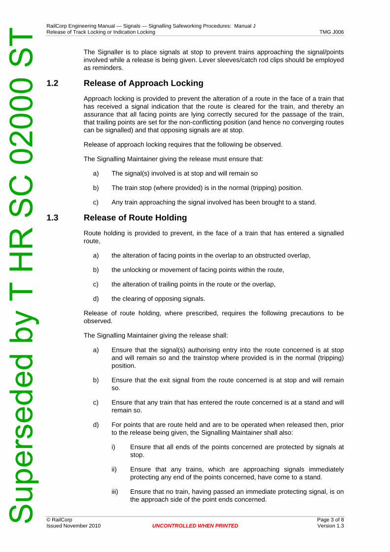
RailCorp Engineering Manual — Signals — Signalling Safeworking Procedures: Manual J Release of Track Locking or Indication Locking TMG J006
© RailCorp Page 3 of 8 Issued November 2010 UNCONTROLLED WHEN PRINTED Version 1.3
The Signaller is to place signals at stop to prevent trains approaching the signal/points involved while a release is being given. Lever sleeves/catch rod clips should be employed as reminders.
1.2 Release of Approach Locking
Approach locking is provided to prevent the alteration of a route in the face of a train that has received a signal indication that the route is cleared for the train, and thereby an assurance that all facing points are lying correctly secured for the passage of the train, that trailing points are set for the non-conflicting position (and hence no converging routes can be signalled) and that opposing signals are at stop.
Release of approach locking requires that the following be observed.
The Signalling Maintainer giving the release must ensure that:
a) The signal(s) involved is at stop and will remain so
b) The train stop (where provided) is in the normal (tripping) position.
c) Any train approaching the signal involved has been brought to a stand.
1.3 Release of Route Holding
Route holding is provided to prevent, in the face of a train that has entered a signalled route,
a) the alteration of facing points in the overlap to an obstructed overlap,
b) the unlocking or movement of facing points within the route,
c) the alteration of trailing points in the route or the overlap,
d) the clearing of opposing signals.
Release of route holding, where prescribed, requires the following precautions to be observed.
The Signalling Maintainer giving the release shall:
a) Ensure that the signal(s) authorising entry into the route concerned is at stop and will remain so and the trainstop where provided is in the normal (tripping) position.
b) Ensure that the exit signal from the route concerned is at stop and will remain so.
c) Ensure that any train that has entered the route concerned is at a stand and will remain so.
d) For points that are route held and are to be operated when released then, prior to the release being given, the Signalling Maintainer shall also:
i) Ensure that all ends of the points concerned are protected by signals at stop.
ii) Ensure that any trains, which are approaching signals immediately protecting any end of the points concerned, have come to a stand.
iii) Ensure that no train, having passed an immediate protecting signal, is on the approach side of the point ends concerned.
Sup
erse
ded
by T
HR
SC
020
00 S
T

RailCorp Engineering Manual — Signals — Signalling Safeworking Procedures: Manual J Release of Track Locking or Indication Locking TMG J006
© RailCorp Page 4 of 8 Issued November 2010 UNCONTROLLED WHEN PRINTED Version 1.3
iv) Ensure that no train or vehicle is foul of any of the point ends concerned.
e) In any instance where it is intended to by-pass a train with a second train, by releasing converging points that are route held by the first train, then the Signalling Maintainer giving the release shall be assured that the driver of the first train is aware that another train will be signalled across the path of his/her train.
1.4 Release of Approach Stick Relays
Approach locking in approach stick relay circuits may be released as follows:
The Signalling Maintainer giving the release shall:
a) After receiving a request from the Signaller for the release and an entry made in the train register book or on Infrastructure Booking Authority form NRF 003.
b) Ensure that the signal is at stop and will remain so, and that the train stop, where provided, is in the tripping position.
c) Ensure that any train approaching the signal involved is at a stand.
d) Momentarily bridge the approach stick finger contact on the approach stick relay. The bridge must be removed immediately.
If the relay does not pick up traffic is to be conducted in accordance with Network Rule NSG 608 until the situation is rectified.
1.5 Release of NI Lever Locks on Signal levers.
Signal NI lever locks apply signal normal indication locking and generally incorporate approach locking and also, in some cases, route holding locking.
The Signalling Maintainer giving the release shall:
a) After receiving a request from the signaller for the release and an entry made in the train register book or on Infrastructure Booking Authority form NRF 003.
b) Ensure that the signal involved is at stop and will remain so and that the train stop, where provided, is in the tripping position.
c) Ensure that any train approaching the signal, or on track circuits included in the NI lock circuit, is at a stand and clear of any points in the route ahead of the signal.
d) Manually lift the lock while the signal lever is placed full normal.
1.6 Release of Normal and Reverse Indication Locks on Point Levers
Normal or reverse indication locks on point levers apply indication locking and do not incorporate track locking.
Normal indication (NI) locks and Reverse indication (RI) locks on points levers may be released when the electric lock has failed to enable the points lever to be placed to the full normal or reverse position in correspondence with the points.
The Signalling Maintainer giving the release shall:
Sup
erse
ded
by T
HR
SC
020
00 S
T

RailCorp Engineering Manual — Signals — Signalling Safeworking Procedures: Manual J Release of Track Locking or Indication Locking TMG J006
© RailCorp Page 5 of 8 Issued November 2010 UNCONTROLLED WHEN PRINTED Version 1.3
a) After receiving a request from the signaller for the release and an entry made in the train register book or on Infrastructure Booking Authority form NRF 003.
b) Ensure that the points are lying in the position corresponding with the position of the point lever and are securely locked by the facing point lock, where provided.
c) Ensure that the points won't be unlocked or moved prior to giving the release, if necessary by electrically disconnecting the points or by clipping and locking the points.
d) Manually lift the respective indication lock while the lever is placed fully over by the Signaller.
If, after the release has been given, the points are found to be still out of order, the indication lock shall not be released again until the points have been disconnected or secured by clip and SL Lock.
Provided the points have been disconnected, and Network Rule NSG 608 and Procedure NPR 740 are in effect, the failed indication lock may be permanently released, if this is necessary, to enable the lever to be placed in correspondence with the points normal or reverse in order to obtain the sequence of the interlocking (when defective points are being manually operated and clipped and locked).
Note:
While the lever is in the normal indication (NI) or reverse indication (RI) position, no traffic must be allowed to pass over the facing points unless they are properly secured by clip and SL lock.
1.7 Release of Normal and Reverse Locks on Point or FPL Levers.
Normal and Reverse locks on point or F.P.L. levers incorporate track locking, generally both approach locking and route holding.
Normal and Reverse locks on point or facing point lock levers may be released when the electric lock is inoperative due to lock failure or approach locking.
The Signalling Maintainer giving the release shall:
a) After receiving a request from the signaller for the release and an entry made in the train register book or on Infrastructure Booking Authority form NRF 003.
b) ensure all protecting signals are at stop and will remain so and that train stops where provided are in the tripping position.
c) ensure any approaching train has been brought to a stand.
d) ensure that no train is foul of any of the connections worked by the points lever.
e) manually lift the electric lock while the lever is moved by the signaller.
If subsequent releases are required, this may be done provided the Signalling Maintainer and Signaller sign an entry in the Train Register Book. When this has been done the Signalling Maintainer may give a separate release for each lever movement required by the Signaller provided all steps (a) to (e) are followed for each release.
As an alternative to releasing the lock each time, the points must be secured with a clip and SL lock and a handsignaller stationed at them to act under the directions of the Signaller in accordance with Network rule NSG 608 and Procedure NPR 740. When this has been done and the entry prescribed by Network rule NGE 234 has been made in the
Sup
erse
ded
by T
HR
SC
020
00 S
T

RailCorp Engineering Manual — Signals — Signalling Safeworking Procedures: Manual J Release of Track Locking or Indication Locking TMG J006
© RailCorp Page 6 of 8 Issued November 2010 UNCONTROLLED WHEN PRINTED Version 1.3
Train Register Book and form Infrastructure Booking Authority form NRF 003 made out and signed, the lock may be permanently released or removed until repairs have been effected.
Note:
In hybrid installations containing both mechanical and relay interlocking, the Signalling Maintainer shall, in addition to the above, ensure that all relay interlocked functions are non-conflicting before a normal or reverse electric lock is released on a point or facing point lock lever.
Note:
The above procedure may also be used to release track locking (route holding) where a train has passed the outer protecting signal and has come to a stand at the immediate protecting signal provided the Signalling Maintainer has been assured and an entry made in the train register book or on Infrastructure Booking Authority form NRF 003 that the driver of this train has been informed that another train is to cross his/her path.
1.8 Release of Signal Normal Indication (NI) Relays or Signal Route Normal Relays
Failure of signal normal indication relays (standard relay interlockings) or signal normal route lock relays (route control relay interlockings) may be released as follows only if extensive train delays would otherwise occur.
If the failure is due to track locking then a release of the approach stick relay is to be provided.
If the failure is due to another cause then a release may be provided as under.
The Signalling Maintainer giving the release shall:
a) After receiving a request from the Signaller for the release and an entry made in the train register book or on Infrastructure Booking Authority form NRF 003.
b) ensure that the signal involved is at stop and will remain so and that the trainstop where provided is in the tripping position.
c) electrically disconnect the signal to prevent its operation and book it out of use
d) ensure that any approaching train has come to a stand
e) momentarily energise the NI relay or NLR relay (after driving the RLR relay down, if necessary). Immediately remove the false feed.
f) Conduct traffic past the disconnected signal in accordance with Network Rule NSG 608.
1.9 Release of Point Lock Relays at Standard Relay Interlockings (Not Route Control Type Interlockings)
Point lock relays in N.S.W. standard relay interlockings apply track locking, generally route holding and in some cases approach locking.
If approach stick relays are provided in the point lock relay circuit and approach locking needs to be released then the respective procedure for releasing approach stick relays shall be provided.
Sup
erse
ded
by T
HR
SC
020
00 S
T

RailCorp Engineering Manual — Signals — Signalling Safeworking Procedures: Manual J Release of Track Locking or Indication Locking TMG J006
© RailCorp Page 7 of 8 Issued November 2010 UNCONTROLLED WHEN PRINTED Version 1.3
In exceptional circumstances it may be necessary to energise a point lock relay to minimise excessive train delays. The relay may be energised after the following precautions have been observed:
a) After receiving a request from the signaller for the release and an entry made in the train register book or on Infrastructure Booking Authority form NRF 003.
b) ensure all protecting signals are at stop and will remain so and that train stops where provided are in the tripping position.
c) ensure any approaching train has been brought to a stand.
d) ensure that no train is foul of any of the connections worked by the points lever.
e) momentarily energise the point lock relay while the points are operated by the Signaller. Immediately remove the false feed.
Where it is necessary to bypass a train occupying route holding track circuits, provided that in addition to the above the Signalling Maintainer is assured that the driver of the train to be by-passed is made fully aware of the by-passing movement and a notation to this effect is made on the release form by the Signaller, the Signalling Maintainer may give the release.
1.10 Release of a Point Lock Relays at Route Control Type Interlockings
At Route Control type relay interlockings if a failure occurs in the circuit of a point lock relay, traffic must be conducted in accordance with Network Rule NSG 608 until the defect has been rectified, except as set out below.
At these interlockings in addition to track locking, the point lock relay circuits incorporate interlocking functions which must not be released.
In exceptional circumstances, if a failure of a point lock relay circuit occurs due to a failure of the track locking within the circuit, or if for other reasons, it is necessary to release the points with the route holding tracks occupied, and it is ascertained that the failure cannot be rectified quickly to avoid serious train delays, then the applicable point lock relays may be energised as follows to allow the point lock relays to be placed in correspondence with the points which have been operated locally by hand by the Signalling Maintainer in the case of EP points, or wound over in the case of electrically operated points, and have been secured by clip and SL lock.
The Signalling Maintainer must fully explain the circumstances to the controlling officer and obtain permission to effect the release as follows:
a) After receiving a request from the signaller for the release and an entry made in the train register book or on Infrastructure Booking Authority form NRF 003.
b) The Signalling Maintainer giving the release shall:
i) ensure that all signals that interlock with the points are normal and that any approaching trains are at a stand;
ii) ensure that any points or releases which interlock with the points are in non-conflicting positions;
iii) ensure there are no trains on routes over the points concerned;
iv) ensure that no train or vehicle is foul of any of the connections worked by the points lever.
Sup
erse
ded
by T
HR
SC
020
00 S
T

RailCorp Engineering Manual — Signals — Signalling Safeworking Procedures: Manual J Release of Track Locking or Indication Locking TMG J006
© RailCorp Page 8 of 8 Issued November 2010 UNCONTROLLED WHEN PRINTED Version 1.3
c) Place the point lever in route control interlockings to the position in correspondence with the points and fit lever sleeves on any signals which control routes which lead over any connections of the points.
d) In the point lock relay circuit concerned, bridge the appropriate contacts applying track locking and double check that the correct contacts and only those contacts are bridged. Then place the point lever to the centre position and observe the points 'free' indication. The Signaller shall then operate the point lever to the position concerned. Remove the bridge immediately the respective point lock relay picks up and check that the opposite point lock relay is down.
Note 1:
No attempt shall be made to operate the point lock relay or the points by operating route set buttons.
Note 2:
No contacts in the point lock relay circuit are to be bridged except those that apply track locking and on no account shall point lock relays be lifted or unplugged and replaced by a relay in the up position.
e) Where it is necessary to by-pass a train which is occupying the route holding track circuits which lock the points to be used for the by-passing movements, then, provided that in addition to the above requirements the driver of the train to be by-passed is made fully aware of the by-passing movements and that a notation to this effect is made in the train register book or on Infrastructure Booking Authority form NFR 003 by the signaller, the Signalling Maintainer may provide the release.
f) Separate requests and entries in the train register book or on Infrastructure Booking Authority form NFR 003 must be completed and a separate release must be given on each occasion it is necessary to operate the point lock relays and the points.
Sup
erse
ded
by T
HR
SC
020
00 S
T
RailCorp Engineering Manual — Signals — Signalling Safeworking Procedures: Manual J Apparatus Seldom Used TMG J007
© RailCorp Page 1 of 12 Issued April 2012 UNCONTROLLED WHEN PRINTED Version 2.1
TMG J007
APPARATUS SELDOM USED
Version 2.1
Issued April 2012
Document control
Version Date Summary of change Replaced SC 00 52 00 07 SI Apparatus Seldom Used
1.0 Sept 2005 New RailCorp format 1.1 9 March 2009 Rewrite of standard 1.2 May 2009 Section 2.2.4 becomes 2.3 & Section 2.2.3 becomes 2.4,
subsequently incremented following Sections to 2.5 & 2.6. Correction of typing errors
1.3 May 2010 Application of TMA 400 format 2.0 November 2010 Added provisions in section 2.4 Power Operated Points Left Operational
Old section 3 becomes section 2.7 Where Impractical To Operate Points Moved 72 hour rule items from TMGJ025 into new 3 section Added testing requirements following periods of track circuit non-use. Added risk assessment considerations for allowing safe use of signalling system when apparatus is seldom used.
2.1 April 2012 Clarify the requirement to book seldom used points out of use where they are impractical to operate for maintenance purposes.
Contents 1 Introduction .............................................................................................................................3
1.1 Closed Signal Boxes..................................................................................................3 2 Seldom Used Points ...............................................................................................................3
2.1 Emergency Crossovers .............................................................................................4 2.1.1 Ground frames released by Releasing Switches .......................................4 2.1.2 Ground frames released by Duplex Lock or similar
arrangement ...............................................................................................4 2.2 Crossovers for Out of Course Working......................................................................4
2.2.1 Power operated points disconnected.........................................................4 2.2.2 Power operated points disconnected for an extended period....................4
2.3 Power Worked Points at Sidings or Refuges.............................................................5 2.4 Power Operated Points Left Operational...................................................................5 2.5 Points at Sidings or Refuges Operated by an Adjacent Ground Frame
or Control Panel.........................................................................................................6 2.6 Installed Points Not Connected to the Signal Interlocking.........................................6 2.7 Where Impractical to Operate Points during Maintenance........................................6
Sup
erse
ded
by T
HR
SC
020
00 S
T

RailCorp Engineering Manual — Signals — Signalling Safeworking Procedures: Manual J Apparatus Seldom Used TMG J007
© RailCorp Page 2 of 12 Issued April 2012 UNCONTROLLED WHEN PRINTED Version 2.1
3 Seldom Used Track Circuits ..................................................................................................73.1 Risk Mitigation ...........................................................................................................7 3.2 Factors for Consideration ..........................................................................................8 3.3 Application of the 72 hour Rule .................................................................................9 3.4 Period of Non Use Affecting Wider Areas ...............................................................10
3.4.1 Track circuited areas at risk .....................................................................10 3.4.2 Testing adequate track shunt after a period of non use...........................10
Sup
erse
ded
by T
HR
SC
020
00 S
T

RailCorp Engineering Manual — Signals — Signalling Safeworking Procedures: Manual J Apparatus Seldom Used TMG J007
© RailCorp Page 3 of 12 Issued April 2012 UNCONTROLLED WHEN PRINTED Version 2.1
1 Introduction Signalling apparatus which is not used very often or never used owing to a change in traffic conditions shall be maintained in accordance with TMG J007, unless special approval is issued to the contrary by the Chief Engineer Signals and Control Systems on lines which traffic is suspended (ref TMG J017).
1.1 Closed Signal Boxes
Where signalling equipment is worked from a signal box which only opens occasionally, the apparatus shall be specially maintained upon notice being given that the signal box is to be brought into use.
2 Seldom Used Points Typically, seldom used points are as follows:
• Emergency crossovers operated by adjacent ground frame or control panel • A power worked double-ended crossover provided for out of course working • Remotely operated power worked points at sidings or refuges • Points at sidings or refuges operated by an adjacent ground frame or adjacent
control panel • Installed points not connected to the signal interlocking
Whenever points become seldom used, the risk of poor track shunt over the unused portion of a track circuit shall be mitigated, generally by the disconnection and booking out of use - signals and/or points, or otherwise by applying suitable and effective controls as determined by the Maintenance Signal Engineer prescribed in Section 2.4.
Where the points are booked out of service due to seldom use, and before a train is allowed to pass over the seldom used points, the Signalling Maintainer shall be present to certify the points fit for use prior to inserting the relevant fuses to permit operation of the points as requested, otherwise points must be clipped and SL locked for the intended move.
Except in the case described in Section 2.3, signals booked out of use as part of the risk mitigation strategy, shall not be re-connected until adequate shunting of the track is established and the points are certified fit for use.
Where the points are being operated manually in emergency conditions, all the signalled routes reading over them shall be booked out of use and disconnected.
Such seldom used points shall be listed at the Signal Box concerned.
Track circuits situated over seldom used points shall be included in a Contaminated Rail Register kept by the Maintenance Signal Engineer.
Note:
There may be situations where an approved arrangement is installed that is designed to operate with rusty rails, such as perway sidings and emergency crossovers that are power worked. In these cases, the specific interlocking arrangements provide inherent protection from the risks of rusty rail and such installations may be left fully operational irrespective of the rail shunt condition of the turnout route.
Sup
erse
ded
by T
HR
SC
020
00 S
T

RailCorp Engineering Manual — Signals — Signalling Safeworking Procedures: Manual J Apparatus Seldom Used TMG J007
© RailCorp Page 4 of 12 Issued April 2012 UNCONTROLLED WHEN PRINTED Version 2.1
2.1 Emergency Crossovers
Emergency crossovers are operated from an adjacent ground frame or adjacent control panel. On-site attendance provides an adequate control against the risk of a train left foul of points or running lines.
2.1.1 Ground frames released by Releasing Switches
Ground frames released by releasing switches are interlocked with protecting signals. In this case, each end of the emergency crossover shall be kept clipped and XL locked in the Normal position.
Signalling Maintainers are to examine the points in accordance with the Technical Maintenance Plan (TMP) and at intervals prescribed in the document. Where the points are impractical to operate for maintenance purposes, they shall be booked out of use and maintained as a minimum requirement, to the items listed in Section 2.7.
Where Safety Critical inspections are performed every 30 days as prescribed in the TMP and the points are fully operated in either direction, an SL lock can be fitted to the point clip(s) in lieu of the XL lock.
2.1.2 Ground frames released by Duplex Lock or similar arrangement
Ground frames released by duplex lock or similar arrangement do not offer the same protection as provided by a releasing switch. In this case, each end of the emergency crossover shall be kept clipped and XL locked in the Normal position.
Signalling Maintainers are to examine the points in accordance with the TMP and at intervals prescribed in the document. Where the points are impractical to operate for maintenance purposes, they shall be booked out of use and maintained as a minimum requirement, to the items listed in Section 2.7.
2.2 Crossovers for Out of Course Working
Some crossovers are provided for out-of-course working. To ensure their readiness and to maintain reliable operation of the track circuit over the points reverse, sufficient trains shall be timetabled through the crossover to clean the rail surfaces. Signalling Maintainers shall check that the rail surfaces on these crossovers are kept clean enough to maintain an effective shunt of the points track circuits involved.
Where inadequate track shunt is evident, the following risk control measures shall apply:
2.2.1 Power operated points disconnected
Seldom used power operated points shall be booked out of use, disconnected and SL locked in accordance with TMG J009. This is the preferred arrangement as the points whilst inoperative, can be easily maintained ensuring a desirable level of reliability. The signalled routes reading through the seldom used portion of track are also to be booked out of use and disconnected.
Signalling Maintainers are to examine the points and associated signalling apparatus in accordance with the TMP and at intervals prescribed in the document.
2.2.2 Power operated points disconnected for an extended period
Where points are booked out of use for an extended period, and the likelihood of restoration is low, the points may be XL locked and spiked in addition to the requirements of Section 2.2.1.
Sup
erse
ded
by T
HR
SC
020
00 S
T

RailCorp Engineering Manual — Signals — Signalling Safeworking Procedures: Manual J Apparatus Seldom Used TMG J007
© RailCorp Page 5 of 12 Issued April 2012 UNCONTROLLED WHEN PRINTED Version 2.1
This arrangement does not allow the points to be maintained easily and in most cases it would be impractical to arrange the points to be operated for maintenance purposes. Signalling Maintainers therefore shall perform as a minimum requirement, the inspection items listed in Section 2.7 at intervals prescribed in the TMP.
2.3 Power Worked Points at Sidings or Refuges
A greater level of risk exists where power operated points located at sidings or refuges become seldom used. In this situation, where inadequate track shunt is evident, there is a possibility that power operated points could be operated with a portion of the train foul of the turnout or a portion of the train left foul of the running line. In this case, the points and signalled routes through the turnout must be booked out and disconnected.
The points are to be clipped and XL locked.
These controls require the presence of a qualified person to provide direct observation, ensuring the train is not left foul of the points or the running line prior to restoring the operating facility.
It is preferable to have the shunt signal clear for the train entering into the siding or refuge thus providing an assurance that points within the route are in the correct position and locked. In this case, Signalling Maintainers are to be present to unclip and reconnect the points to allow the points to be operated to the desired position and resecure the point-clip. The fuse for the protecting shunt signal may then be reinserted to allow the signal to operate over the points.
Upon assuring the train is wholly within the siding or refuge and not left foul of the turnout or the running line, the signal is to be disconnected and points reinstated to the original position, disconnected, clipped and XL locked.
Where a Signalling Maintainer is unavailable, trains must be worked into the siding or refuge by a qualified person in accordance with the Network Rules & Procedures.
This arrangement does not allow the points to be maintained easily and in most cases it would be impractical to arrange the points to be operated for maintenance purposes. Therefore the points shall be maintained as a minimum requirement, to the items listed in Section 2.7 at intervals prescribed in the TMP.
2.4 Power Operated Points Left Operational
If the seldom used portion of a turnout is part of a run-off and there is no signal move for the turnout, then the points may be left operational.
Power operated points may also be left operational in certain circumstances to facilitate the maintenance of selective overlaps or to maximise the safe use of the signalling system eg; where it may be preferable to leave the route setting functional (with signals disconnected) to ensure points within the route are set in their correct position. These provisions shall be conditional upon a proper risk assessment conducted by the Maintenance Signal Engineer with outcomes determined as an acceptable level of risk.
Factors that Maintenance Signals Engineers should consider when determining the level of acceptable risk are prescribed in section 3.2.
Signal Maintenance Engineers shall advise the Principal Engineer Signal Operations & Assurance of the determination made to keep points operational and of the associated controls put in place as part of the risk mitigation strategy.
Sup
erse
ded
by T
HR
SC
020
00 S
T

RailCorp Engineering Manual — Signals — Signalling Safeworking Procedures: Manual J Apparatus Seldom Used TMG J007
© RailCorp Page 6 of 12 Issued April 2012 UNCONTROLLED WHEN PRINTED Version 2.1
Not withstanding any of the above, Signalling Maintainers shall continue to maintain the apparatus in accordance with the TMP and at intervals prescribed in the document unless alternative arrangements are approved by the Chief Engineer Signals and Control Systems.
2.5 Points at Sidings or Refuges Operated by an Adjacent Ground Frame or Control Panel
Where seldom used points are located at sidings or refuges operated by an adjacent ground frame or an adjacent control panel and the operator can easily observe the clearance point or other end of points, then the ground frame releasing arrangements may be left connected.
Where observation of the clearance point is not easily sighted, then the releasing arrangements are to be disconnected.
Each end of points shall be kept clipped and locked in the Normal position.
Signalling Maintainers are to examine the points in accordance with the TMP and at intervals prescribed in the document. Where the points are impractical to operate for maintenance purposes, they shall be booked out of use and maintained as a minimum requirement, to the items listed in Section 2.7.
Where Safety Critical inspections are performed every 30 days as prescribed in the TMP and the points are fully operated in either direction, then an SL lock can be fitted to the point clip(s). In all other cases the points shall be locked with an XL lock.
2.6 Installed Points Not Connected to the Signal Interlocking
Where a set of points is to be installed as a precursor to being connected to the signal interlocking or where the signal interlocking equipment is removed from a set of points pending removal, the points need to be adequately secured in accordance with the Signal Design Principle for Points - ESG100.14.
The maintenance of securing devices of points not connected to the signal interlocking must be scheduled at intervals as prescribed in the TMP or otherwise at 30 days. The tasks listed in Section 2.7 shall apply as a minimum requirement.
2.7 Where Impractical to Operate Points during Maintenance
Generally, points booked out of use are examined in accordance with the TMP at the intervals prescribed in the document.
However, where it is impractical to operate points for maintenance purposes, the following examination procedure must be followed to ensure a high level of integrity for the signalled routes that remain operational through the points in the Normal position.
In this case, the usual facing point lock (including claw lock or spherolock) and detection tests may be waived provided the examinations listed below are performed within the scheduled intervals as prescribed in the TMP.
Note: Certain other scheduled maintenance activities may also be waived during the extended period that the points remain booked out of use, provided the reliability and integrity of the working signalling is not jeopardised. For example, insulation testing of detection circuits that affect working signals is still required in accordance with the TMP. Full maintenance service shall resume prior to the points being booked back into use.
Sup
erse
ded
by T
HR
SC
020
00 S
T
RailCorp Engineering Manual — Signals — Signalling Safeworking Procedures: Manual J Apparatus Seldom Used TMG J007
© RailCorp Page 7 of 12 Issued April 2012 UNCONTROLLED WHEN PRINTED Version 2.1
a) Check the releasing arrangements are locked, including manual operating levers locked by special lock or Falcon 8 (as applicable).
b) Check there is no damage to any of the equipment or rodding.
c) Check all fastenings are secure and of the correct type (eg; nyloc).
d) Check the point spikes, clips and locks are securely fitted.
e) Ensure the point FPL's are securely plunged or claw lock or spherolock is effectively locking the points.
f) Check the closed switch is securely against the stock rail throughout its entire length and that the backdrive is not moving or flogging during train passage.
g) Ensure the detection mechanism is in its proper position (where applicable, using a 1mm / 2mm go/no go gauge as described in TMGE1341) and is secure.
h) Check the stretcher rods securely maintain the open switch in its correct position and provide minimum flange-way clearance.
i) Check there is no evidence of excessive movement or wear of the channel iron route or in the case of power operated points, the point mechanism gearbox is secured to prevent drifting (latched in the case of EP claw lock or spherolock points).
j) Check there is no evidence of excessive movement or wear of the perway at the points.
k) Inspect parallel bonds, including the hypalon insulation, the termination to rail and the clips holding the bonds or conduit to sleepers are all in good condition and secure. Where parallel bonds are not visible over their entire length, the continuity of the bonds is to be tested using a suitable tong ammeter.
3 Seldom Used Track Circuits Signalling Maintainers shall take every opportunity to inspect rail surface, observing for rust or other contaminants that may reduce the effectiveness of a good track shunt, particularly sections of track that are prone to seldom use including sidings, entry/exit points, refuges, branch lines, crossovers etc.
Whenever Signalling Maintainers become aware of rails that are rusty or otherwise contaminated such that the track circuit would not detect the presence of a train, they shall book out of use the affected signals/route controls and points and immediately advise the Maintenance Signal Engineer of the details. Potential problem sections of track shall also be reported.
The Maintenance Signals Engineer shall then determine an appropriate strategy for dealing with contaminated rail.
3.1 Risk Mitigation
Routine maintenance visits may need to be scheduled more frequently where the likelihood of contaminants prevail and a risk assessment has determined this requirement as part of a risk mitigation strategy.
Sup
erse
ded
by T
HR
SC
020
00 S
T

RailCorp Engineering Manual — Signals — Signalling Safeworking Procedures: Manual J Apparatus Seldom Used TMG J007
© RailCorp Page 8 of 12 Issued April 2012 UNCONTROLLED WHEN PRINTED Version 2.1
Maintenance Signal Engineers shall maintain a register of contaminated rail for track circuits on their area which are likely to be rusty and cause loss of train detection. They are to ensure that the potential for this is minimised by an appropriate mitigation strategy that would protect against the risk factors shown in section 3.2. Maintenance Signal Engineers and Signalling Maintainers shall be alert for changes in the rolling stock type, service operating frequency and tonnage in their area.
Maintenance Signal Engineers are to specify any change needed to the general requirement period of 72 hours nominated in Network rule NGE 220 and advise the Principal Engineer Signal Operations & Assurance of any more stringent requirements for ensuring track circuits do not fail to detect trains because of rusty rail and/or light weight trains and/or infrequent services.
Where a lesser period or longer are required for specific sections, the Maintenance Signal Engineer is to advise this as an exception to the general requirements. For example, reductions might be to 48 hours for non electrified main line areas and to 24 hours for non electrified branch line areas, longer periods may be due to the provision of impulse track circuits. Once approved, the Maintenance Signal Engineer shall arrange to implement these changes with Network Operations.
The decision to ensure the integrity of track circuits relative to the potential loss of track shunt due to contaminated rail needs to be determined on site.
3.2 Factors for Consideration Relevant factors that shall be considered when conducting a risk assessment for allowing the safe use of the signalling system to operate when apparatus is seldom used include:
• Effectiveness of Track Shunt - type of track circuit used, eg; impulse track circuit - loose or light coating of rust that can be easily cleaned - random contaminants causing intermittent loss of shunt - new or seldom used and heavily rusted rail, causing high likelihood for loss
of shunt • Location of Contaminated Rail
- does the area affect clearance point(s) - can a whole train or light engine be undetected - does the contamination span the entire track circuit - does the contamination span several track circuits - is a tuned loop affected
• Environment & Configuration
- does the area involve long straight or tangent track allowing smooth rolling of wheels on rails
- is the affected area part of a siding or refuge - do contaminated turnout rails form part of mainline crossover - are all rails in the points contaminated (turnout & straight) - are points operated from an adjacent ground frame or adjacent panel - do affected track circuits operate level crossing protection equipment - is the area prone to high humidity, rainfall, temperature extremes - rail susceptibility to rusting due to surrounding environment (eg; air borne
contaminants, ocean salt spray)
Sup
erse
ded
by T
HR
SC
020
00 S
T
RailCorp Engineering Manual — Signals — Signalling Safeworking Procedures: Manual J Apparatus Seldom Used TMG J007
© RailCorp Page 9 of 12 Issued April 2012 UNCONTROLLED WHEN PRINTED Version 2.1
• Maintenance/Administrative Controls - effective monitoring - regular grinding - utilisation of a temporary stop block to reduce risk - certain signal routes left connected subject to an acceptable level of risk - the arrangement of more frequent services - determine if manual safeworking operation would cause a higher risk - determine if blocking facilities applied to controls in lieu of apparatus
disconnection would cause a higher risk • Rolling Stock
- do trains with electric traction operate on the affected line - is the line normally designated for mixed rail traffic - do freight trains only operate on the affected line - do light engines operate on the affected line - what are the lengths/consists of typical rolling stock - speed of short light trains - axle loading & number of axles per train, gross tonnage - do rail vehicles have tread conditioning from brake shoes or only disk
brakes used - time and frequency between trains - wheel/rail profile interaction, variance of wheel to rail contact band
(especially the risk of "hollow" wheels) - would changes to the TOC manual provide an acceptable risk - do rail contaminants come from the type of train
Where adverse conditions exist and/or an infrequent or light weight traffic service runs, measures such as five second slow pick-up track repeat relays or impulse track circuits may be necessary. These options shall be discussed with the Chief Engineer Signals & Control Systems and the Signal Design section.
3.3 Application of the 72 hour Rule
The application of the 72 hour rule was designed for main line operations or frequently used lines where the rail head surface was already clean and free of contaminants (bright shiny) and maintained in that condition by the normal timetabled running and where the line was intermittently closed for periods of less than 72 hours.
The application of running one short train over a section of track circuited line once every 72 hours does not allow adequate cleaning of the rail head surface and over an extended period of time, allows a slow build-up of rust and other contaminants to accumulate, resulting in the subsequent intermittent loss of track circuit shunt.
The term "infrequently used lines" appears in a number of safeworking documents. For signalling purposes, "infrequently used lines" when applied to light engines or equivalent, refers to track circuited lines that have had less than the equivalent of six eight car trains or 5,000 tonnes traverse them at or near line speed in a 24 hour period.
The action of a train travelling at or near line speed, especially freight trains, has a "scrubbing effect" on the top of the rail head keeping it free from contaminants and rust. However there is a difference between the behaviour of a light engine & an electric train on the track circuits on "infrequently used lines". The electric train, because of the large traction current drawn, will break down contaminants on the rail head allowing the track circuit to shunt more effectively. This may result in a different safeworking requirement for electric rolling stock as to light engines or similar rail vehicles when applying to a tracked circuited line that comes under the category of an “Infrequently used lines”.
Sup
erse
ded
by T
HR
SC
020
00 S
T

RailCorp Engineering Manual — Signals — Signalling Safeworking Procedures: Manual J Apparatus Seldom Used TMG J007
© RailCorp Page 10 of 12 Issued April 2012 UNCONTROLLED WHEN PRINTED Version 2.1
3.4 Period of Non Use Affecting Wider Areas
Where rail traffic has stopped operating for periods greater than 72 hours affecting large areas of track circuited lines, suitable arrangements shall be put in place by the relevant Infrastructure Maintenance Districts involved. Whilst Maintenance Signal Engineers are responsible for ensuring that effective mitigation strategies are in place for events that could instigate non use of lines in these cases, adequate support shall be provided by the groups responsible for possession planning.
Periods of non use may be instigated by possession work, train strike or alteration to normal timetables or freight operations.
Proper and timely notification, liaising and planning with relevant parties are required to ensure that risks associated with loss of track shunt are managed effectively as to not cause a reduction in signalling integrity.
3.4.1 Track circuited areas at risk
Rail lines affected by possessions can be considered as follows:
• Track circuits directly worked on within the possession area: Risks associated with this work are mitigated by the relevant signalling safeworking procedure (eg; rerailing).
• Track circuits within a possession area, but are clear of track work: These track circuits are at risk of not providing effective track shunt if not used for a period of greater than 72 hours.
• Track circuits outside a possession area, but not used due to an operational variance caused by the possession:
These track circuits are at risk of not providing effective track shunt if not used for a period of greater than 72 hours.
3.4.2 Testing adequate track shunt after a period of non use
A risk assessment endorsed by the Maintenance Signal Engineer shall be arranged to form a strategy for testing following periods of non use - greater than 72 hours.
Testing shall provide an assurance of satisfactory track shunt. The method and scope of testing will vary dependant upon the reason for the event, length and track configuration, type of trains operating, weather conditions and the period of non use.
Testing strategies may require re-evaluation if the scope of work or possession arrangements alter throughout the period of non use.
Trains may be block worked through the affected sections until the lines are certified for normal operation.
Certification of the track circuits and subsequent running of train services must not exceed 24 hours from the conclusion of testing.
The following methods may provide an assurance of satisfactory track shunt. Maintenance Signal Engineers may determine that a combination of these tests is required.
Sup
erse
ded
by T
HR
SC
020
00 S
T

RailCorp Engineering Manual — Signals — Signalling Safeworking Procedures: Manual J Apparatus Seldom Used TMG J007
© RailCorp Page 11 of 12 Issued April 2012 UNCONTROLLED WHEN PRINTED Version 2.1
• Train Shunt Check: A Train Shunt Check, as prescribed in TMG J025, conducted over a selected sampling of affected track circuits, can assist to provide a confident assessment of track shunt capability for the affected area before certifying the track circuits into use. Consideration should be given to the type of track circuits in use, selecting a higher sampling rate from track circuits with a lesser shunting characteristic. Track circuits nominated in a contaminated rail register for the affected area should be included in the sample test. Consideration should also be given to the relevant factors listed in section 3.2.
• Competent Person Travelling on a Test Locomotive: Utilising a competent person travelling on a test locomotive who is capable of communicating their exact position in reference to track circuit, to a suitably licensed signalling person located in the signal box for the area being observed. The licensed signalling person is responsible for observing and ensuring that all track indications operate in correspondence as the test locomotive occupies and unoccupies each track circuit within the section of affected track prior to certifying the track circuits into use. The test must be conducted in a manner that each individual track circuit is clearly differentiated from the next. The generation of track sequencing alarms (if available) shall also be taken into account.
• Test Locomotive or Tabled Trains Traversing Under Block Working: A test locomotive or tabled trains, block worked in accordance with NGE 220, can be used to operate on the affected line(s) with a suitable licensed signalling person observing each affected track circuit indication and ensuring its operation as satisfactory as the locomotive/train traverses the section before certifying the track circuits into use. The generation of track sequencing alarms (if available) shall also be taken into account.
Sup
erse
ded
by T
HR
SC
020
00 S
T
RailCorp Engineering Manual — Signals — Signalling Safeworking Procedures: Manual J Apparatus Seldom Used TMG J007
© RailCorp Page 12 of 12 Issued April 2012 UNCONTROLLED WHEN PRINTED Version 2.1
This page has been intentionally left blank
Sup
erse
ded
by T
HR
SC
020
00 S
T

RailCorp Engineering Manual — Signals — Signalling Safeworking Procedures: Manual J Booking Signalling Equipment OUt of use TMG J008
© RailCorp Page 1 of 6 Issued August 2012 UNCONTROLLED WHEN PRINTED Version 1.2
TMG J008
BOOKING SIGNALLING EQUIPMENT OUT OF USE
Version 1.2
Issued August 2012
Document control
Version Date Summary of change
1.0 September 2005 Replaced SC 00 52 00 08 SI Booking Signalling Equipment Out of Use
1.1 May 2010 Application of TMA 400 format 1.2 August 2012 Introduction: Added the requirement for advertising in the Weekly
Notice where signalling equipment is booked out of use for an extended period (greater than 6 months) or indefinitely.
Contents 1 Introduction .............................................................................................................................2
1.1 Protection of Derailment Sites ...................................................................................3 1.2 Failure Investigation (in cases where investigation and rectification
would not affect safety integrity) ................................................................................4 1.3 Work which could affect safety integrity ....................................................................4
Sup
erse
ded
by T
HR
SC
020
00 S
T

RailCorp Engineering Manual — Signals — Signalling Safeworking Procedures: Manual J Booking Signalling Equipment OUt of use TMG J008
© RailCorp Page 2 of 6 Issued August 2012 UNCONTROLLED WHEN PRINTED Version 1.2
1 Introduction (Refer also to TMG J009)
Signalling equipment is referred to as “booked out of use”:-
a) When there is manual intervention to secure signalling equipment in a safe, de-energised or locked position so that it will not be operated as part of the safeworking system for the signalled movement of trains.
b) Alternatively, when the equipment is manually disconnected from the interlocking and this intervention formally documented and signed accordingly on Infrastructure Booking Authority form NRF 003 and in a Train Register Book or in other documents provided for the purpose.
Signallers may temporarily book controlled signalling equipment out of use by utilising lever sleeves or equivalent to secure signal levers in the normal position, or points levers in the normal or reverse position, or facing point lock levers in the points locking position, or by appropriately applying blocks to the signalling equipment concerned. Generally in these cases the signaller makes an entry in the Train Register Book or other book provided for the purpose. (However, by itself, this is not an acceptable level of protection if signalling equipment is to be disconnected from the interlocking or if the interlocking apparatus is to be disarranged).
When signalling employees are required to book signalling equipment out of use, they shall disconnect the equipment as a matter of course, (except in particular signalling irregularity investigations where it may be necessary to not disturb equipment which has failed wrong-side). They should also request the signaller to place a lever sleeve or block on the respective controlling levers, keys or pushbuttons. Disconnection should be carried out as described in procedure TMG J009 “Disconnection of Signalling Apparatus”.
Signalling Maintainers are to use Infrastructure Booking Authority form NRF 003 to book signalling equipment out of use and back into use in accordance with Network rules & Procedures NWT 312 and NPR 704 in order to ensure that there is an understanding reached with the Signaller of the work and the safeworking precautions to be taken, and to ensure that the affected signalling equipment is properly certified fit for use before being booked back into use.
In many cases testing to certify the equipment will involve operating the “booked-out” equipment from the signaller’s control panel and this must be done with the Signaller’s agreement under strict controls directed by the Signalling Maintainer in charge, in circumstances where it is safe to do so and where there is no possibility of endangering train movements or of drivers or operators acting on the operation of the equipment while it is being tested but still booked out of use.
Generally the NRF 003 form is to be used whenever signalling equipment is disconnected and out of use for traffic operations or when it is restored to use for traffic operations, that is:-
a) when signalling interlocking apparatus is disarranged.
or
b) when signalling equipment is disconnected from the interlocking, (includes temporary bridging of contacts of circuit control devices)
or
Sup
erse
ded
by T
HR
SC
020
00 S
T

RailCorp Engineering Manual — Signals — Signalling Safeworking Procedures: Manual J Booking Signalling Equipment OUt of use TMG J008
© RailCorp Page 3 of 6 Issued August 2012 UNCONTROLLED WHEN PRINTED Version 1.2
c) when signalling equipment that has been disconnected from the interlocking is restored to use
or
d) when signalling trackside equipment is rendered inoperative by disconnection of the power to motors and mechanisms and/or to control devices (but the equipment remains connected to the interlocking) and the equipment is left unattended or requires the provision of handsignallers for traffic movements
or
e) when work is being carried out on signalling equipment or circuits and there is risk of endangering the safe operation of the signalling system, or risk of incorrect restoration which could cause a signalling irregularity, or there is otherwise a risk to the safety of the line.
Signalling Maintainers are responsible for compiling NRF 003 form with the Signaller where work is to be carried out which involves disarrangement of the interlocking apparatus, or disconnection from the interlocking of signals, trainstops, points, facing point locks, locking bars, detectors, level crossing gates, boom barriers or type F flashing lights, or of track circuits affecting any of the foregoing.
Additionally, where signalling equipment is booked out of use for an extended period (greater than 6 months) or indefinitely, suitable arrangements shall be made for advertising these details in the Weekly Notice.
It is also necessary to disconnect, and maintain in a safe state, other signalling equipment which protects and interlocks with the signalling equipment that is disconnected from the interlocking or is affected by disarrangement of the interlocking apparatus.
These protecting signals and points, while not to be disconnected ‘from the interlocking’, are to be disconnected and maintained in a safe position (by removal of the power supply to the motors, mechanisms and/or control devices) and included on the NRF 003 form by the Signalling Maintainers involved.
Where work which affects the signalling is being carried out under total possession the signalling equipment which is to be disconnected from the interlocking and the associated protecting signals and points which would also normally be disconnected are still required to be disconnected and booked out of use on the NRF 003 form.
Where signalling apparatus is disconnected in order to render it inoperative and out of use for traffic operations, (but still safely connected to the interlocking), the suitably accredited Signalling Maintainer shall also compile the NRF 003 form and include this equipment as booked out of use.
In all cases, completing and signing the NRF 003 form for restoring signalling equipment to use, constitutes certification that the interlocking apparatus and signalling equipment that was disarranged or disconnected or which could have been affected, has been tested and is safe and fit to restore to normal use.
1.1 Protection of Derailment Sites
At derailment sites where the signalling employee disconnects signalling equipment to protect the site, the standard practice shall be to book out of use and disconnect all signals and points which lead into the sections of track which are obstructed by derailed vehicles. Signal routes through points which are disconnected and held in the opposite position to lead clear of the obstruction, need not be disconnected, but signals with their
Sup
erse
ded
by T
HR
SC
020
00 S
T

RailCorp Engineering Manual — Signals — Signalling Safeworking Procedures: Manual J Booking Signalling Equipment OUt of use TMG J008
© RailCorp Page 4 of 6 Issued August 2012 UNCONTROLLED WHEN PRINTED Version 1.2
overlap extending over an obstructed section of track shall be disconnected. In exceptional circumstances, disconnection may be limited to the immediate protecting signals and points provided there is no risk of collision with train over-running these protecting signals and provided the approval of controlling signal engineers is obtained.
1.2 Failure Investigation (in cases where investigation and rectification would not affect safety integrity)
When signalling equipment is failed and is being inspected and tested to find and fix the failure, or is being inspected and tested to certify its correct operation, and where such inspection, testing and rectification work will definitely not interfere with the safe operation of the signalling system, then it will not be necessary for signalling employees to book out and disconnect equipment, although Signallers may be requested to keep associated signals at stop, as required, by putting lever sleeves or equivalent on the controlling levers, keys or pushbuttons.
1.3 Work which could affect safety integrity
Whenever there is a possibility of inspection or testing or any other work on signalling equipment interfering with the safe operation of the signalling system, then the signalling equipment being worked on and the affected signals and points must be booked out of use and disconnected.
This is done to prevent the normal passage of trains past any signals, or over any points or level crossings, whose safe operation may be jeopardised by the work or by the testing of the completed work before it is booked back into use.
As a simplified example, if there is rewiring work on points detector contacts in a detection circuit then, in the normal case, the signal routes (including overlaps) which detect those points would be manually disconnected and booked out of use together with the points, even if the detector relay itself is not touched and is disconnected at cable links and isolated from the work on the detector contacts. (If the signal routes requiring the detector relay circuit were not disconnected and booked out of use then, if the detector circuit were wrongly reconnected, it may be possible that signals could be unsafely cleared, perhaps inadvertently).
When the rewiring work is completed the detector relay would be reconnected and the detector circuit would be fully inspected, tested and certified to be physically and functionally correct, while the affected signals remained disconnected. In this particular example, because it could be guaranteed that the detector relay itself and its contacts were isolated from the work and not touched, no further testing of the interlocking and controls would be necessary and the disconnected signals could be reconnected and booked back into use together with the points. Notwithstanding, because the signals have been disconnected, they are to be operated to test they are in working order before being booked back into use; beforehand, the Signaller is to be informed that the signals are being reconnected for test but are still out of use, and a check is to be made that any handsignallers are advised accordingly, and that there are no trains approaching that could be affected by the signal clearing during the testing.
Note :
Signalling equipment is disconnected ‘from the interlocking’ when the disconnection affects the integrity of the interlocking provided for the safety of train movements.
Other than for power supplies to signal lights, level crossing warning equipment and the like, the removal of power supply fuses, and the opening of circuits at terminal captive links or link pins or at indexed plug connectors, (if this secures signalling apparatus in a
Sup
erse
ded
by T
HR
SC
020
00 S
T

RailCorp Engineering Manual — Signals — Signalling Safeworking Procedures: Manual J Booking Signalling Equipment OUt of use TMG J008
© RailCorp Page 5 of 6 Issued August 2012 UNCONTROLLED WHEN PRINTED Version 1.2
de-energised, fail-safe position), would not be considered as disconnection ‘from the interlocking’.
The ‘interlocking’ is that part of the signalling system which applies the interlocking and track locking between conflicting routes, signals, trainstops, points, level crossing warning systems and which applies track circuit control to the clearance of signals and level crossing warning systems, and it includes all the vital control, indication and detection equipment and circuits that provide and prove correspondence between the respective signals, trainstops, points, track circuits and level crossing warning systems and the rest of the ‘interlocking’.
Sup
erse
ded
by T
HR
SC
020
00 S
T
RailCorp Engineering Manual — Signals — Signalling Safeworking Procedures: Manual J Booking Signalling Equipment OUt of use TMG J008
© RailCorp Page 6 of 6 Issued August 2012 UNCONTROLLED WHEN PRINTED Version 1.2
This page has been intentionally left blank
Sup
erse
ded
by T
HR
SC
020
00 S
T

RailCorp Engineering Manual — Signals — Signalling Safeworking Procedures: Manual J Disconnection of Signalling Apparatus TMG J009
© RailCorp Page 1 of 16 Issued February 2013 UNCONTROLLED WHEN PRINTED Version 1.8
TMG J009
DISCONNECTION OF SIGNALLING APPARATUS
Version 1.8
Issued February 2013
Document control
Version Date Summary of change 1.0 Replaced SC 00 52 00 09 SI Disconnection of Signalling Apparatus 1.1 14/01/2008 Added type ES to lists in 1.3 1.2 5/09/2008 Fix page numbering problem (e.g. Page 15 of 13). Also added
“Uncontrolled when Printed” in Footer. 1.3 March 2009 Amended 1.5 Level Crossing Protection – to accommodate new
EMR arrangement. Removed reference to power worked semaphore signals
1.4 May 2010 Corrected reference to TMG J004 in 1.3.2.2. Application of TMA 400 format
1.5 October 2010 Specify requirement for D84M points after manual operation in 1.3 Clarify the purpose of EMR arrangements in 1.5
1.6 March 2011 Referenced TMG J016 for operating signalling controls. Added new paragraph 1.1 for reference to CBI installations (note increment of subsequent paragraph numbers).
1.7 August 2012 Introduction: Added the requirement for advertising in the Weekly Notice where signalling equipment is booked out of use for an extended period (greater than 6 months) or indefinitely.
1.8 February 2013 Added High Voltage Impulse track circuits as an exception to disconnecting Feed & Relays ends in section 1.8. Clarified section 1.9 for booking out during Routine Maintenance
Contents 1 Introduction .............................................................................................................................3
1.1 Disconnection of Signalling Apparatus at Computer Based Interlocking (CBI) Installations ......................................................................................................3
1.2 Disconnection of Signals ...........................................................................................4 1.3 Disconnection of Points - Mechanical........................................................................4
1.3.1 Exception....................................................................................................5 1.4 Disconnection of Points - Power Operated................................................................5
Electric – All Types ....................................................................................................5 Electro – pneumatic Style C, D, E, S N & ES control valves units ............................6 Style E, S & ES modified control valves units ...........................................................6 Style T control valves units ........................................................................................6
Sup
erse
ded
by T
HR
SC
020
00 S
T

RailCorp Engineering Manual — Signals — Signalling Safeworking Procedures: Manual J Disconnection of Signalling Apparatus TMG J009
© RailCorp Page 2 of 16 Issued February 2013 UNCONTROLLED WHEN PRINTED Version 1.8
Style A control valves units........................................................................................6 1.4.1 Disconnection of Points for Work on the Points: Points
Detection in Working Order........................................................................7 1.4.2 Disconnection of Points for Work on the Points: Points
Detection Not in Working Order .................................................................8 1.4.2.1 Normal Case ...............................................................................8 1.4.2.2 Exceptional Case ........................................................................8 1.4.2.3 Unplanned Work During a Planned Possession.......................11
1.4.3 Disconnection of Points for Indefinite Period ...........................................11 1.5 Removal of Sidings..................................................................................................11 1.6 Level Crossing Protection........................................................................................12
1.6.1 General.....................................................................................................12 1.6.2 Where Trackwork affects the Operation of Level Crossing
Equipment ................................................................................................12 1.6.3 Level Crossings fitted with Master Emergency (EMR)
Arrangements...........................................................................................12 1.6.4 Level Crossing not fitted with an EMR Arrangement ...............................13 1.6.5 Disconnection of Level Crossing Protection ............................................13
1.7 Disconnection of Electric Locks and Releasing Switches .......................................13 1.8 Disconnection of Track Circuits ...............................................................................13 1.9 Routine Maintenance...............................................................................................14
Sup
erse
ded
by T
HR
SC
020
00 S
T

RailCorp Engineering Manual — Signals — Signalling Safeworking Procedures: Manual J Disconnection of Signalling Apparatus TMG J009
© RailCorp Page 3 of 16 Issued February 2013 UNCONTROLLED WHEN PRINTED Version 1.8
1 Introduction Whenever it is necessary to disconnect signalling apparatus (mechanical or electrical) the provisions of Network Rule and Procedure NWT 312 and NPR 704 shall be strictly observed. Refer also to Procedure TMG J008.
The Signalling Maintainer in charge of the work shall check that a suitable entry has been made in the 'Train Register Book', and, where practical, sign it after the signaller.
All involved in the work shall ensure there is a common understanding of who is in charge and responsible for these safeworking arrangements.
When it is necessary under the provisions of Network Rule and Procedure NWT 312 and NPR 704 for a 'Hand Signaller' to be provided in connection with the disarrangement of interlocking apparatus, or disconnection of points, signals, trainstops or level crossing warning systems from the interlocking, such 'Hand Signaller' shall be provided and work under the directions of the Signaller.
Signalling Maintainers shall not interfere with the connections until they have assured themselves that the required 'Hand Signaller' is in position.
Safe working form NRF 003 shall be filled in and countersigned by the Signaller/Network Control representative, in accordance with Network Rule and Procedure NWT 312 and NPR 704.
When the work involves the disarrangement of permanent way equipment (e.g. where rails, points or crossings are re- laid, removed or repaired) safeworking form NRF 003 shall also be used, and signed jointly by the Signalling, Network Control and Civil officers in charge.
When it is necessary to operate a signalling control during the execution of the work, then this shall be done in accordance with TMG J016 section 2.
When the apparatus which has been disconnected is again in working order, the Signalling Maintainer shall cause the signaller to make an entry in the 'Train Register Book', counter sign the entry, where practical, and fill in particulars on form NRF 003 and sign in conjunction with the Signaller/Network Control representative, and Civil representative where applicable.
Whenever any signalling apparatus is electrically disconnected by the removal of fuses, pins or links and the Signalling Maintainer cannot remain in attendance, then the points of disconnection shall be securely and clearly labelled to prevent the possibility of someone inadvertently replacing the fuse or pin or closing the link.
Additionally, where signalling equipment is booked out of use for an extended period (greater than 6 months) or indefinitely, suitable arrangements shall be made for advertising these details in the Weekly Notice.
1.1 Disconnection of Signalling Apparatus at Computer Based Interlocking (CBI) Installations
The following prescribed disconnection methods predominantly apply to hard wired or mechanical signalling systems. Where the interlocking system is computer based, then the specific methods for inhibiting (disconnecting) signalling apparatus for the purpose of signalling safeworking shall be observed in conjunction with the relevant parts of this procedure. In these cases, the following procedures shall be additionally referenced:
Sup
erse
ded
by T
HR
SC
020
00 S
T

RailCorp Engineering Manual — Signals — Signalling Safeworking Procedures: Manual J Disconnection of Signalling Apparatus TMG J009
© RailCorp Page 4 of 16 Issued February 2013 UNCONTROLLED WHEN PRINTED Version 1.8
• TMG J032 Solid State Interlocking (SSI) • TMG J038 Microlok Computer Based Interlocking • TMG J039 Westrace Computer Based Interlocking
1.2 Disconnection of Signals
When it is necessary to disconnect a signal to prevent its operation and maintain it at stop, the signal control circuit fuse shall be removed. The motor operating fuse of the associated trainstop shall also be removed.
Generally, on colour light signals, securely disconnect both the active (positive) leg and the common (negative) leg of the signal control relay circuit for the lowest proceed indication in the sequence, typically the caution (HR) relay circuit but in some cases the low speed (LSpR) relay circuit. Also disconnect the active (positive) or common (negative) legs of the signal control relay circuits for the higher indications in the signal.
On installations such as Sydney and Strathfield, where route termination links are provided this facility is used to disconnect the route(s) of the signal concerned instead of removing the common signal control circuit fuse.
Advise the signaller of the circumstances and request blocking facilities be applied to the signal lever.
In conjunction with any main line signal being disconnected and maintained at stop, the distant signals or equivalent shall also be arranged to be securely maintained at their correct restrictive indications ie., the mechanical distant signal shall be disconnected and maintained at caution and, in the case of power worked signals, the signal immediately in rear shall be maintained at caution, or low speed, as applicable, with the respective lower yellow, lower green or clear relay circuits etc., controlled by the main signal prevented from operating.
The respective control relay circuits for the higher indications of the signal in rear shall be disconnected by manually opening either the active (positive) or common (negative) legs of the circuits.
(Where the respective higher signal indications of the signal in the rear are double switched by the disconnected control relays for the main line signal and where the integrity of these circuits is not in doubt, then the manual disconnection is unnecessary.)
When it is necessary to disconnect a mechanical signal to prevent the operation of the signal, and maintain the signal in the stop position (Caution if distant signal), the catch rod handle shall be disconnected by removing the pivot pin, and a lever sleeve fitted to the lever, and in addition the signal wire is to be slackened off at the wire adjuster or with the GNR wheel for distant signals where provided.
Signals shall not be operated by hand from the stop position. (Should it be necessary to momentarily move the semaphore arm of a stop signal for maintenance, the Signalling Maintainer shall ensure there is no train approaching that could accept the signal arm movement as authority to proceed.)
1.3 Disconnection of Points - Mechanical
When it is necessary to disconnect mechanical points to prevent their operation the catch rod handles for the FPL lever and the point lever concerned shall be disconnected. Lever sleeves shall be fitted to the FPL lever and the points lever.
The procedures described above render the points inoperative but still safely connected to the interlocking with the points locked in position and the signals detecting and
Sup
erse
ded
by T
HR
SC
020
00 S
T

RailCorp Engineering Manual — Signals — Signalling Safeworking Procedures: Manual J Disconnection of Signalling Apparatus TMG J009
© RailCorp Page 5 of 16 Issued February 2013 UNCONTROLLED WHEN PRINTED Version 1.8
interlocked with the points. In such circumstances, provided the facing points are clipped and SL locked, the signals leading over the points may be left in order.
When it is intended that the points are to be further interfered with, worked on, manually operated or disconnected from the interlocking, then, in addition to the above, the signals protecting the points shall also be disconnected and maintained at stop and the associated distant signals or equivalent (ie., higher indications of the signals immediately in the rear) are to be disconnected so that these signals are restricted to a caution indication, or low speed, as applicable. Traffic moves shall be conducted with the points clipped and SL locked, and with the disconnected signals handsignalled.
1.3.1 Exception
If it is intended to work on the channel iron lead to the points or facing point lock and the points will not be moved during the course of this work it will be permissible to leave the protecting signals in working order provided the following precautions are observed.
a) Book the points and facing point lock out of order on form NRF 003.
b) Sign the required entry in the Train Register Book
c) Disconnect the catchrod of both the points lever and the facing point lock lever so that the levers and the interlocking cannot be moved out of correspondence with the points.
d) Disconnect the plunger of the facing point lock and securely wire the plunger into the plunger casting to securely lock the points.
e) Secure the points with clip and SL lock.
f) Provided the detection is in order and no attempt will be made to move the points, the signals leading through the points may be left working.
g) This procedure can only be adopted while the site is permanently attended by Signalling Maintainers; if it is required that the protecting signals remain operating while the Signalling Maintainers are not in attendance the points must also be spiked and XL locked in accordance with the procedures for 'Crossovers Seldom Used'.
1.4 Disconnection of Points - Power Operated
Electric – All Types When it is necessary to electrically disconnect power worked points to prevent their operation, the following arrangements shall apply; where the points are electrically operated the local power shall be disconnected from the motor by the removal of the motor operating fuse. The isolating switch shall also be switched to the off position. This shall be carried out for each point end worked from the points lever.
Note:
In the case of Westinghouse D84M point machines, where these points are booked out of use and disconnected, and the detection is still in working order for the purpose of train running, then a Signal Engineering representative shall control the process whenever there is a necessity to manually (hand) operate the points. The Signal Engineering representative shall ensure the points have fully operated to the desired position and additionally check that the dog-clutch has engaged following the manual operation prior to handing back the points detection to the Signal Box.
Sup
erse
ded
by T
HR
SC
020
00 S
T

RailCorp Engineering Manual — Signals — Signalling Safeworking Procedures: Manual J Disconnection of Signalling Apparatus TMG J009
© RailCorp Page 6 of 16 Issued February 2013 UNCONTROLLED WHEN PRINTED Version 1.8
To enforce this requirement, the EOL for the points operated by a Westinghouse D84M machine shall be locked with a Falcon 8 lock for the period that the points remain booked out of use.
Electro Pneumatic (EP) Points Style C, D, E, S, N & ES control valves units Where points are electro pneumatically operated and the point motor does not require “air on” continuously to prevent sagging back or switch creep (typically Signal Branch EP), the air shall be cut off. In addition to the air being removed the circuit fuse to the plunger lock valve (PLW) for each point end is to be removed for points controlled by style ‘C’, ‘D’, ‘E’, ‘S’, ‘ES’ and ‘N’ (Newcastle) control valve units.
Style E, S & ES modified control valves units EP Claw Lock points require “air on” continuously to prevent sag back against the motor latch and possible open switch creep and are not to be isolated from the air when disconnected to prevent their operation. Where the points are controlled by modified ‘S’, ‘E’ & ES control valve units for “air on” operation, the circuit fuse for the points operating solenoid opposite to that which the points are laying is to be removed. ie when the points are laying normal the fuse for the reverse solenoid (RW) circuit is to be removed or the normal solenoid (NW) fuse when the points are laying reverse.
Style T control valves units Where points are fitted with ‘T’ control valves for trailable operations, the cut off solenoid (LW) when de-energised maintains air to the respective side of the point’s motor for which the points are laying. When the LW solenoid is energised this allows the points to become trailable, therefore removal of the circuit fuse for the cut off valve solenoid (LW) is not recommended. These points are to be disconnected in accordance with the arrangements for modified ‘S’ and ‘E’ controls valves as detailed above.
Style A control valves units Where the points are controlled by an ‘A’ valve unit they are to be electrically isolated by the removal of the circuit fuse for the points contactor relay opposite to that which the points are laying. ie when the points are laying normal the fuse for the reverse points relay (RWR) circuit is to be removed or the normal points relay (NWR) circuit fuse when the points are laying reverse.
Note:
As an additional precaution the air slide valve to the side of the motor opposite to that which the points are laying may be turned off. It is recommended that where the points are to be booked out of order for an extended period (in excess of 72 hours) this arrangement should be implemented.
The electrically disconnected points shall be securely and clearly labelled to prevent the possibility of someone inadvertently replacing the fuses, closing links, switching on the power and/or turning on the air.
The signaller is to be advised of the circumstances and request blocking facilities be applied to the points lever for the position the points are in.
The method of disconnection of points in computer based interlocking (CBI) areas is described in the respective Sections in this manual dealing with the particular type of computer based interlocking.
Sup
erse
ded
by T
HR
SC
020
00 S
T
RailCorp Engineering Manual — Signals — Signalling Safeworking Procedures: Manual J Disconnection of Signalling Apparatus TMG J009
© RailCorp Page 7 of 16 Issued February 2013 UNCONTROLLED WHEN PRINTED Version 1.8
Note:
The procedures described above render the points inoperative but still safely connected to the interlocking with the points locked in position and the signals detecting and interlocked with the points. In such circumstances the signals leading over the points may be left operating provided that,
• if the electrically disconnected points are to be left unattended or out of use, the facing ends of the points are to be clipped and SL locked and form NRF 003 is to be filled in.
• the interlocking of the signals with the points is in proper working order, and will remain so.
• the point switches, connections and operating mechanisms are in proper adjustment and working order, and will remain so,
• the electrical detection is in proper adjustment and working order, and will remain so.
• the facing point lock is securely plunged and locking the switch hard against the stock rail, with the lock unable to be withdrawn due to the points being electrically (and electro-pneumatically where applicable) disconnected to prevent their operation.
• no attempt will be made to manually unlock or move the points. • the points are to be electrically disconnected for a limited period of time. When
points will be out of use for an indefinite period the procedures detailed in TMG J007 Apparatus Seldom Used shall be applied.
If it is intended that the points are to be further interfered with, worked on, manually operated or disconnected from the interlocking, then, in addition to the above, the signals protecting the points shall also be disconnected and maintained at stop and the associated distant signals or equivalent (ie., higher indications of the signals immediately in rear) are to be disconnected so that these signals are restricted to a caution indication, or low speed, as applicable. Traffic moves shall be conducted with the points clipped and SL locked and with the disconnected signals handsignalled. The requirements of Network Rule and Procedure NWT 312 and NPR 704 shall be observed.
Where ESML arrangements (Emergency Switch Machine Lock, Annett Key and attached crank handle) on electric points machines or EOL arrangements on E.P. points machines are provided for the manual operation of power worked points, the disconnection of the points and the protecting signals is accomplished automatically through use of the ESML or EOL arrangements. Similarly where Plug Connector and Key arrangements are utilised with Style D or Style E operated electro-pneumatic points, the affected signals and points are automatically disconnected. The ESML, EOL or Plug Connector and Key arrangements may be utilised during failure conditions and also for testing of facing point locks and detectors.
Electro-pneumatic points, and particularly those utilising type S, A and T valve units, must not be blown over by manipulating the valves unless it is assured that the points and affected signals on all lines have been securely disconnected by use of the EOL arrangements, where applicable, or by disconnection of Plug Connectors, (D, E & ES valves), where applicable, or for Style C valve & N (Newcastle) units by manual disconnection of the points detector circuit.
1.4.1 Disconnection of Points for Work on the Points: Points Detection in Working Order
Where work is to be carried out on power worked points fitted with electrical detection, then, in some cases, the signals leading over one or more of the ends of such points, and over the diamond crossings may be left working if it is safe to do so provided the following precautions are observed.
Sup
erse
ded
by T
HR
SC
020
00 S
T

RailCorp Engineering Manual — Signals — Signalling Safeworking Procedures: Manual J Disconnection of Signalling Apparatus TMG J009
© RailCorp Page 8 of 16 Issued February 2013 UNCONTROLLED WHEN PRINTED Version 1.8
a) Advise the signaller of the work to be done and request blocking facilities be applied to the points lever.
b) Fill in form NRF 003. Observe NWT 312 and NPR 704.
c) Electrically disconnect the points and turn the power off (electric or electro-pneumatic) to prevent their operation.
d) Clip and SL lock the points facing ends which are being worked on or are liable to be affected by the work.
e) If the points detection is in working order and will remain so, and if all ends that are or could be affected by the work are clipped and locked, the signals over the points may be left working while the Signalling Maintainer is in attendance to ensure the clips and SL locks are not removed. If the Signalling Maintainer cannot remain in attendance and if the integrity of the facing point lock cannot be relied upon, then the SL lock is to be changed to an XL lock and the points are also to be spiked, or otherwise the signals leading over the points ends and the diamond crossings are to be disconnected and maintained at stop, until the points are restored to use.
1.4.2 Disconnection of Points for Work on the Points: Points Detection Not in Working Order
1.4.2.1 Normal Case
a) Advise the signaller of the work to be done and request blocking facilities be applied to the points lever.
b) Fill in form NRF 003. Observe NWT 312 and NPR 704.
c) Electrically disconnect the points and turn the power off (electric or electro-pneumatic) to prevent their operation.
d) Clip and SL lock the facing ends of the points.
e) Clip and SL lock the trailing ends of the points.
f) Disconnect and maintain at stop the signals leading over the points ends and the diamond crossings and disconnect the mechanical distant signal or restrict the power worked signal in rear to a caution indication (or low speed where applicable).
1.4.2.2 Exceptional Case
Note:
The following procedure may also be applied when the points detection equipment has failed and the time to repair and the traffic delays will be extensive (refer to TMG J004 1.6.6).
(Where points are booked out of use and are clipped, XL locked and spiked pending removal, the detection, if in order, should be left in circuit and not bridged.)
With the points lying normal the signals leading over the trailing end, and over the diamond crossings on a middle road, may be allowed to work if it is safe to do so, by remaining connected and by bridging detection, provided the following precautions are strictly observed.
Sup
erse
ded
by T
HR
SC
020
00 S
T

RailCorp Engineering Manual — Signals — Signalling Safeworking Procedures: Manual J Disconnection of Signalling Apparatus TMG J009
© RailCorp Page 9 of 16 Issued February 2013 UNCONTROLLED WHEN PRINTED Version 1.8
a) Explain the work to and obtain authorisation on Form ‘Authority for Temporary Bridging of Contacts’ from the appropriate Authorising Officer (see procedure TMG J002).
Observe the requirements of TMG J002 ‘Bridging or False Feeding of Signalling Circuits’.
b) Advise the signaller and request blocking facilities to be applied to the points lever.
c) Compile Form NRF 003 booking the points out of use, include the notation ‘BRIDGED’ against the entry of the points booked out of use and sign the form.
Observe the requirements of NWT 312 and/or NPR 704, as applicable.
d) Electrically disconnect the points and turn the power off to prevent their operation. (Mechanical points shall have the catch handle rod of the point lever and the FPL lever disconnected to prevent their movement.)
e) In all cases, clip and SL lock the facing ends of the points.
f) Also clip and SL lock the trailing end points for traffic movements (in addition to the facing end points) if the work is being carried out on the trailing end points, or if the detection is out of order on the trailing end.
g) Disconnect and maintain at ‘Stop’ the signals leading over the facing ends of the points and disconnect the mechanical distant signal or restrict the power worked signal in rear to a caution indication (or low speed where applicable).
h) Disconnect the reverse detector circuit at the same location where the normal contacts are being bridged.
i) Bridge the detection contacts for the position the points are lying using regulation jumper wires (see procedure TMG J002), as follows:
i) Using the regulation jumper wires, strap and function test the contacts to be bridged to prove they are the correct contacts, then leave the bridging connected.
ii) Bridge only the detection contacts that are affected (eg. detector normal contacts or indication box normal contacts or plunger lock normal contacts, as applicable).
iii) Do not bridge out the contacts on points ends that are not affected.
iv) Do not bridge out the ESML contact (see Note 2 for exception).
v) Apply the bridging at the actual detection contacts where the detection is out of order, if practical. If this is not practical apply the bridging at the nearest respective cable terminals to the contacts themselves and open the cable links leading back to the contacts; correspondence must firstly be proved between the cable terminals and the respective detection contacts.
j) Once the bridging is applied, function test the point detection contacts at the end that is not affected to verify they are still effectively in the detection circuit.
k) Remain in attendance at the points while the bridge is on to ensure the points are not unclipped or unlocked, unless this can be otherwise guaranteed.
Sup
erse
ded
by T
HR
SC
020
00 S
T
RailCorp Engineering Manual — Signals — Signalling Safeworking Procedures: Manual J Disconnection of Signalling Apparatus TMG J009
© RailCorp Page 10 of 16 Issued February 2013 UNCONTROLLED WHEN PRINTED Version 1.8
l) REMOVE the bridging BEFORE the point clips and locks are removed.
REMOVE the bridging BEFORE the points are electrically reconnected.
REMOVE the bridging BEFORE the signals leading over the facing ends are reconnected.
REMOVE the bridging BEFORE reconnecting the reverse detector circuit.
m) Operate the points and function test the detection contacts through to the signallers panel BEFORE the points are booked back into use.
n) Complete the NRF 003 form and sign into use.
o) Advise the Authorising Officer that the bridging has been removed.
p) Authorising Officer completes the ‘Authority for Temporary Bridging of Contacts’
Note 1:
Facing end detection in order and facing end not affected by the work
If the work does not involve the facing end of points, and the detection is not bridged out on the facing end, and if (after the bridging is applied on the point ends affected by the work) the points normal detection on the facing end is tested and proved to be in working order, then, provided the facing end is clipped and SL locked normal and provided all other aspects of the above procedure are observed, the signals leading over the unaffected facing end of the points in the normal direction may be restored to use, if specifically authorised by the Authorising Officer for the temporary bridging.
Note 2:
Bridged points detection not permanently attended.
If it is not practical for Signalling Maintainers to remain in attendance all the time that the bridging is on then other precautions must be taken to ensure that the bridging will not be interfered with and points will not be unlocked or moved or restored to use before the bridging is removed and the detection tested. These precautions need to be authorised and documented.
For example, if it cannot be otherwise guaranteed that the points would not be unlocked and if there could be any train movements (including work trains) over ends of the points in a facing direction, then have those points ends XL locked and spiked; if the bridging is to remain on for an extended period, then also obtain authorisation on Form ‘Authority for Temporary Bridging of Contacts’ and bridge the ESML detection contact using regulation jumper wires and remove the ESML crank and key and keep it secure in your custody. Make a notation on the NRF 003 form that the ESML is bridged. Remove the ESML bridging when returning the crank and key.
If unable to remain in attendance while the detection is bridged out, then it will be necessary to close and lock signalling apparatus, disconnection boxes and equipment locations in which case the jumper wires may not remain obvious to any uninformed person becoming involved. Where practical leave the jumper wires protruding, or further disconnect the points near the terminals where the bridging is applied so that to reconnect the points the jumper wires will be noticeable.
Sup
erse
ded
by T
HR
SC
020
00 S
T

RailCorp Engineering Manual — Signals — Signalling Safeworking Procedures: Manual J Disconnection of Signalling Apparatus TMG J009
© RailCorp Page 11 of 16 Issued February 2013 UNCONTROLLED WHEN PRINTED Version 1.8
Note 3:
Work requiring clipped and locked points to be unclipped.
Where one end of a crossover set of points is being worked on and the nature of the work necessitates that the points be unclipped at some stage, then such work is to be carried out with the signals on that line (leading up to and over that end of the points) disconnected and booked out of use with handsignallers provided at the signal(s) for any train movements. The bridging of the points detection on that line must not be applied unless the Signalling Maintainer can ensure that the points will be kept clipped and locked in the non-conflicting (normal) position except for periods when there is no possibility of any train movement (including work trains) up to the points on that line: the Signalling Maintainer is to be in attendance when the points are unlocked or unclipped.
Note 4:
Testing when points equipment disconnected.
If the planned work involves the renewal of the points wiring or the disconnection and removal of more than one wire from its terminal at the one time, then the procedures for renewal or repair of signalling cables and wires are to be observed with testing of the wiring and points correspondence testing to ensure correct reconnection. If there are mechanical disconnections or track or permanent way adjustments then it will be necessary to perform facing point lock and detection tests.
1.4.2.3 Unplanned Work During a Planned Possession
If during the course of a planned possession it becomes obvious that the points equipment is at risk of damage and requires to be disconnected to protect the equipment or, if otherwise it becomes necessary to be disconnected, then bridging of the detection to maintain signalling on adjacent roads which are not affected by the possession, is only permitted if authorised and carried out in accordance with the requirements of Section 1.4.2.2 above.
1.4.3 Disconnection of Points for Indefinite Period
If it is necessary to disconnect either mechanically or power operated points for an indefinite period, the points must be spiked, clipped and XL locked in accordance with Network Rule and Procedure NWT 312 and NPR 704. Also TMG J007 Apparatus Seldom Used shall be referenced.
1.5 Removal of Sidings
When sidings operated by interlocked points are removed the procedures outlined in Network Rule and Procedure NWT 312 and NPR 704 must be observed.
If the siding is not straight railed on the advertised date the points must be spiked, clipped and XL locked, the interlocking equipment disconnected and the requirements prescribed in TMG J007 shall be observed.
NRF 003 forms must be signed by representatives of each discipline.
Subsequently when the siding is straight railed fresh NRF 003 forms will be signed and the siding will be deleted from publications.
Sup
erse
ded
by T
HR
SC
020
00 S
T

RailCorp Engineering Manual — Signals — Signalling Safeworking Procedures: Manual J Disconnection of Signalling Apparatus TMG J009
© RailCorp Page 12 of 16 Issued February 2013 UNCONTROLLED WHEN PRINTED Version 1.8
1.6 Level Crossing Protection
1.6.1 General
Where it is necessary to disconnect level crossing protection equipment (i.e. type 'F' warnings lights, bells, 1/2 arm booms and/or pedestrian warning lights, audible alarms, booms & gates), Signalling Maintainers must first be aware of the different arrangements that apply (i.e. level crossings fitted or not fitted with EMR arrangements).
1.6.2 Where Trackwork affects the Operation of Level Crossing Equipment
It is preferable to have the level crossing operational wherever possible to maximise the safe use of the signalling system.
Where the operation of the level crossing equipment is affected by planned trackwork, the Maintenance Signal Engineer shall evaluate the need to maintain the level crossing in an operational state.
In bi-directional areas where trackwork is conducted on one track only, consideration should be given to obtaining a signal design for bridging out the track control circuits that affect the level crossing, thus permitting the level crossing to operate normally for the unaffected track.
1.6.3 Level Crossings fitted with Master Emergency (EMR) Arrangements
Master Emergency (EMR) arrangements (where fitted) are provided at level crossings to enable full functionality of the level crossing protection equipment during manual operation of the crossing by Qualified Workers during emergencies or planned track work. Full functionality is achieved by operation of the Master Emergency switch and the Manual Operation switch by Qualified Workers irrespective of the availability of level crossing control circuits.
Operation of the Master Emergency switch will deactivate the level crossing operation and cause protecting signal(s) to be retained at Stop allowing road and pedestrian traffic to pass. When it becomes necessary to allow rail traffic to pass, the Manual Operating switch shall be used to activate the warning equipment. When the warning equipment has been proved normal, the protecting signal(s) may clear, subject to other controls (such as track circuits clear, route set, etc) being available.
Whenever the Master Emergency arrangements are in use, the level crossing shall remain attended by the Qualified Worker.
Where the level crossing equipment remains serviceable and it is necessary to operate the level crossing manually for emergencies or planned work, then level crossings with an EMR arrangement need not be disconnected.
However, use of the Master Emergency switch shall not be permissible in the situation where the level crossing warning equipment is required to be formally disconnected and booked out of use. Where disconnection of the crossing is required, it shall be performed in accordance with 1.6.5.
If it is necessary to carry out work on a damaged boom or associated equipment, then the boom shall be tied up (as required) clear of the road and the associated motor operating fuse removed - in conjunction with turning off the relevant Boom Emergency switch to place the boom out of service. Should damage be more extensive and operation of the Master Emergency switch does not cause the level crossing to cease, the arrangements shown in 1.6.5 are to be implemented.
Sup
erse
ded
by T
HR
SC
020
00 S
T

RailCorp Engineering Manual — Signals — Signalling Safeworking Procedures: Manual J Disconnection of Signalling Apparatus TMG J009
© RailCorp Page 13 of 16 Issued February 2013 UNCONTROLLED WHEN PRINTED Version 1.8
1.6.4 Level Crossing not fitted with an EMR Arrangement
In the case where an EMR arrangement is not provided, the level crossing shall be electrically disconnected as described in 1.6.5.
1.6.5 Disconnection of Level Crossing Protection
The crossing control (XR) fuse is to be removed and in addition, where up road and down road control relays are provided the circuit fuse for either relay is also to be removed if that circuit is directly affected i.e. when one or all of the approach track circuits have been disconnected. Where 1/2 arm booms are provided the motor control fuses for the up and down booms are to be removed and the booms arranged to be tied up clear of the road.
Pedestrian crossing booms are not to be tied up or gates held open. If the level crossing is situated on a single line then the up and down direction stick relays circuit fuse is also to be removed.
Where the level crossing is situated in an interlocking and protected by home signals the fixed signals protecting the interlocked level crossing are to be disconnected and maintained at stop and the associated distant signals or equivalent (i.e. higher indications of signals immediately in the rear) are to be disconnected so that these signals are restricted to a caution indication or low speed, as applicable.
In addition, hand signallers must be provided at the level crossing and affected signals, if applicable, in accordance with Network Rules and Procedures NWT 312, NPR 704, NGE 218 and NPR 715.
1.7 Disconnection of Electric Locks and Releasing Switches
When disconnecting a Releasing Switch or Electric lever lock to prevent its operation, the operating circuit fuse is to be removed and the common/negative side is also to be manually open-circuited.
A test is then to be made to ensure that the device is inoperative.
1.8 Disconnection of Track Circuits
When disconnecting track circuits the circuit fuses controlling the FEED and RELAY are to be removed.
The disconnection of FEED arrangements are as follows:
a) For transformer fed track circuits both AC & DC, the transformer primary fuse (typical 120v) and the links on the secondary side of the feed transformer are to be removed.
b) For battery fed track circuits where no fuse is provided an internal feed cable link on either the positive or negative side of the battery is to be open circuited. Alternatively the feed cable connected to the positive terminal (wing-nut) of the battery may be disconnected.
c) For Jeumont track circuits the 120v fuse to the transmitter is to be removed.
d) For Audio Frequency tracks, where a separate power supply is provided the 120v fuse feeding the P/S unit is to be removed. Where the track circuit is fed from a bus bar the fuse (typical 24v) feeding the transmitter is to be removed. Always pull the negative pin or links first before removing the fuse.
Sup
erse
ded
by T
HR
SC
020
00 S
T

RailCorp Engineering Manual — Signals — Signalling Safeworking Procedures: Manual J Disconnection of Signalling Apparatus TMG J009
© RailCorp Page 14 of 16 Issued February 2013 UNCONTROLLED WHEN PRINTED Version 1.8
The disconnection of RELAY arrangements are as follows:
a) For both conventional AC and DC track circuits the track side fuse controlling the relay is to be removed, the local fuse for an AC vane track relay need not be removed. Where no fuse is provided i.e. "some battery fed DC track circuits", one of the internal links on the incoming track cable to the relay is to be open circuited
b) For Jeumont track circuits at least one of the internal links on the incoming cables from the track is to be open circuited.
c) For Audio frequency track circuits the supply fuse to the receiver is to be removed (typical 24V fuse) or, alternatively, if the unit has its own separate power supply, the 120v+ fuse to the P/S may be removed. Always pull the negative pin or links first before removing the fuse.
In electrified areas, when traction return rails are to be broken (e.g. rerailing of a traction return rail) or traction bonding is to be disturbed, the track circuit equipment in the location is to be isolated by open circuiting the cable leads to the track in both the feed and relay end locations to prevent the potential of any traction return current or other extraneous voltages entering the track circuit equipment. This is not required in the case of jointless or high voltage impulse track circuits that incorporate an isolating transformer in the trackside termination.
1.9 Routine Maintenance
The safeworking procedures set out in the Network rules and Procedures shall be applied when working on signalling equipment except during routine maintenance where:
a) There is no interference with the working or interlocking of points, signals or level crossing protection, or
b) Where the work will not disarrange the interlocking or disconnect the signalling equipment from the interlocking but will make points or signals inoperative (or will cause level crossing warning equipment to operate) for a short period of time, provided that an understanding is reached with the signaller and a suitable opportunity between trains exists to enable the work to be completed without detriment either to safety or train working.
If the work cannot be completed within this short time between trains the apparatus concerned must be treated as being defective and the Network rules and Procedures must be applied.
The period of time for this working shall be shorter than the time between trains and less than thirty minutes.
Before undertaking any routine maintenance authorised by b) above, the Signalling Maintainer must advise the Signaller of the work required to be done and agree to when the work shall be carried out. Both parties must co-operate throughout, as necessary.
Note 1:
Section b) above may also be applied to work that will make inoperative (for a very short period of time), the lowering of only one half boom barrier, or the illumination of only one set of lights, of a Type F protected level crossing.
Sup
erse
ded
by T
HR
SC
020
00 S
T

RailCorp Engineering Manual — Signals — Signalling Safeworking Procedures: Manual J Disconnection of Signalling Apparatus TMG J009
© RailCorp Page 15 of 16 Issued February 2013 UNCONTROLLED WHEN PRINTED Version 1.8
Note 2:
Terms above have the following meanings:
Will make points or signals inoperative means that points are unable to be moved and that signals are unable to be cleared from the stop position.
Will cause level crossing warning equipment to operate means that the lights and audible alarms operate and the boom barriers, where applicable, lower to the horizontal position.
The work will not disarrange the interlocking or disconnect signalling equipment from the interlocking means that the vital signalling controls and indications (that prevent signals being wrongly cleared, or prevent points being wrongly moved or released, or that operate level crossing warning equipment) will not be interfered with and will remain effective and the work will not defeat any of the protection provided by the signalling system.
Sup
erse
ded
by T
HR
SC
020
00 S
T
RailCorp Engineering Manual — Signals — Signalling Safeworking Procedures: Manual J Disconnection of Signalling Apparatus TMG J009
© RailCorp Page 16 of 16 Issued February 2013 UNCONTROLLED WHEN PRINTED Version 1.8
This page has been intentionally left blank
Sup
erse
ded
by T
HR
SC
020
00 S
T

RailCorp Engineering Manual — Signals — Signalling Safeworking Procedures: Manual J Risks & Controls Associated with Testing and Certifying Equipment Worked on or Altered During Maintenance TMG J010
© RailCorp Page 1 of 10 Issued December 2011 UNCONTROLLED WHEN PRINTED Version 2.3
TMG J010
RISKS & CONTROLS ASSOCIATED WITH TESTING AND CERTIFYING
EQUIPMENT WORKED ON OR ALTERED DURING MAINTENANCE
Version 2.3
Issued December 2011
Document control
Version Date Summary of change 1.0 12 Sep 2005 Replaced SC 0052 00 10 SI Testing and Certifying Equipment
Worked on or Altered During Maintenance 1.1 30 March 2009 Section 1 new text added re tests for: Documentation, Correlation,
Points out of correspondence, Switch Openings & Facing Point Lock. Uncontrolled when Printed added to Footer
1.2 7 April 2009 Further updated suite of typical inspections and tests 1.3 July 2009 Update requirements for "Correspondence" testing. 2.0 August 2009 Standard name changed & updated in line with SPG 0711.9
implementation 2.1 May 2010 Application of TMA 400 format 2.2 July 2010 Insert section 7 – Renewal of Switches, Stockrails or Turnout
Added Aspect Sequence Test in typical inspection & tests 2.3 December 2011 Amend supervision requirements in reference to Authorised Person
(section 6.0)
Contents 1 Introduction .............................................................................................................................2 2 Assess the Risks, Take Adequate Precautions, Test on Completion ...............................2 3 Alterations Not Affecting the Principle of Circuits ..............................................................5
3.1 Renewal of Signalling Equipment..............................................................................6 4 Alterations Affecting the Principle of Circuits .....................................................................6 5 Relocating or Moving Relay Racks .......................................................................................7 6 Authority to Interfere with Working Signalling Circuits......................................................7
6.1 New Works and Alterations .......................................................................................8 7 Renewal of Switches, Stockrails or Turnout ........................................................................9
7.1 Checklist ....................................................................................................................9
Sup
erse
ded
by T
HR
SC
020
00 S
T

RailCorp Engineering Manual — Signals — Signalling Safeworking Procedures: Manual J Risks & Controls Associated with Testing and Certifying Equipment Worked on or Altered During Maintenance TMG J010
© RailCorp Page 2 of 10 Issued December 2011 UNCONTROLLED WHEN PRINTED Version 2.3
1 Introduction Having assured a safe, operational signalling installation by certification inspection and testing of new works and alterations, it is essential that this integrity is maintained and is not jeopardised by maintenance work that requires some necessary interference with vital parts of the signalling system.
When performing work on signalling equipment which involves disconnection, disarrangement, disassembly or adjustment, Signalling Maintainers shall take adequate precautions during the work and carry out proper tests at the completion of the work, commensurate with the risk of incorrect reconnection, assembly or adjustment and a resultant irregularity. This includes risks associated with polarity reversal.
This standard should be read in conjunction with the following procedures:
TMG J011 - Precautions Associated with Renewals Work TMG J012 - Repair/Replacement of Signalling Wires TMG J021 - Minor Signalling Works performed by Maintenance Groups TMG J025 - Track Circuits SPG 0711.9 - Like For Like Renewal Procedures
2 Assess the Risks, Take Adequate Precautions, Test on Completion Risk is a measure of probability of the undesired event occurring, multiplied by the severity of the consequences.
Whenever a wire is disconnected from its terminal there may be a risk that it could be reconnected to the wrong terminal.
The risk increases with the circumstances, eg: are there other terminals close by; are the terminals and the wires labelled; are they correctly labelled; is more than one wire disconnected at the same time; is the period of disconnection brief or extended; will the person who re-connects the wire be a different person to the one who disconnected the wire; is the person involved unfit, tired or under pressure; is complacency likely; is lighting and access good or poor and awkward; could wrong reconnection lead to an irregularity or would it instantly be detected by a right side failure?
Similarly, if an item of equipment is disconnected or disassembled, or replaced, is there a risk that it could be installed the wrong way around or upside down, and would such wrong assembly be detected by failure or could an irregularity result?
Similarly, if broken wires are repaired there is a risk they could be cross-connected and in certain cases this could cause an irregularity, if undetected.
Sup
erse
ded
by T
HR
SC
020
00 S
T

RailCorp Engineering Manual — Signals — Signalling Safeworking Procedures: Manual J Risks & Controls Associated with Testing and Certifying Equipment Worked on or Altered During Maintenance TMG J010
© RailCorp Page 3 of 10 Issued December 2011 UNCONTROLLED WHEN PRINTED Version 2.3
Signalling Maintainers are to assess these risks when disconnecting wiring and when disconnecting or disassembling equipment and are to take adequate precautions to minimise the risk, for example:
• Mark or label the wires and corresponding terminals. • Wire count and null count the existing equipment and compare this to the specific
circuit design. • Be aware to treat metal links as wires. • Disconnect and reconnect one wire at a time where possible. • Mark matching sides of items of equipment before disassembly. • Improve lighting and access; remove distractions or causes of pressure; apply a
methodical and systematic approach and concentrate the mind on the issues involved.
Most importantly, Signalling Maintainers are to follow up the precautions taken (to eliminate the probability of incorrect reconnection, assembly, repair or replacement) with a series of tests, in accordance with Standard Specification SPG 0711, of the reconnected circuit or item of equipment to ensure it is working correctly. Network rules and Procedures are to be followed wherever they apply.
Similarly, when equipment is adjusted, Signalling Maintainers are to assess the risks, take adequate precautions to eliminate the probability of incorrect adjustment and then carry out tests to verify the correct operation of the adjusted equipment.
In all such cases, where work on vital signalling equipment involves disconnection, disarrangement, disassembly or adjustment, then the principles shall be that:
• The equipment is worked on in accordance with the relevant Network rules and Procedures and these Signalling Procedures.
• Adequate precautions are taken to eliminate the probability of incorrect reconnection, assembly, replacement or adjustment.
• The equipment is tested to function correctly after the work is completed. • The work is recorded with the relevant documents completed and signed by the
Signalling Maintainer which shall signify that it has been tested and functions correctly prior to returning the apparatus into service.
• The documents are submitted to the Maintenance Signal Engineer, who actions it appropriately and retains the documented report on file.
Details shall be submitted on the following signed documents, which shall constitute certification:
• Relevant maintenance record documents (eg: FPL return, work order, etc). • Infrastructure Booking Authority form NRF 003 (if applicable). • A detailed report (if applicable). • A specific work instruction as prescribed in SPG 0711.9 - Like for Like Procedures,
or other work instruction (if applicable).
The Maintenance Signal Engineer shall ensure that reporting and recording procedures are adequate and be satisfied that the work has been properly carried out.
Signalling Maintainers are to select and perform inspections and tests that will satisfy the certification requirements for the particular work.
A list of various types of inspections and tests used to verify correct physical and functional compliance is attached.
Sup
erse
ded
by T
HR
SC
020
00 S
T
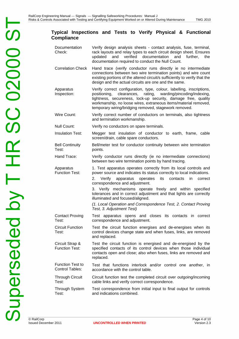
RailCorp Engineering Manual — Signals — Signalling Safeworking Procedures: Manual J Risks & Controls Associated with Testing and Certifying Equipment Worked on or Altered During Maintenance TMG J010
© RailCorp Page 4 of 10 Issued December 2011 UNCONTROLLED WHEN PRINTED Version 2.3
Typical Inspections and Tests to Verify Physical & Functional Compliance
Documentation Check:
Verify design analysis sheets - contact analysis, fuse, terminal, rack layouts and relay types to each circuit design sheet. Ensures updated and verified documentation and further, the documentation required to conduct the Null Count.
Correlation Check Hand trace (verify conductor runs directly ie no intermediate connections between two wire termination points) and wire count existing portions of the altered circuit/s sufficiently to verify that the design and the actual circuits are one and the same.
Apparatus Inspection:
Verify correct configuration, type, colour, labelling, inscriptions, positioning, clearances, rating, warding/pincoding/indexing, tightness, secureness, lock-up security, damage free, quality workmanship, no loose wires, extraneous items/material removed, temporary wiring/bridging removed, stagework removed.
Wire Count: Verify correct number of conductors on terminals, also tightness and termination workmanship.
Null Count: Verify no conductors on spare terminals.
Insulation Test: Megger test insulation of conductor to earth, frame, cable screen/drain, cable spare conductors.
Bell Continuity Test:
Bell/meter test for conductor continuity between wire termination points.
Hand Trace: Verify conductor runs directly (ie no intermediate connections) between two wire termination points by hand tracing.
Apparatus Function Test:
1. Test apparatus operates correctly from its local controls and power source and indicates its status correctly to local indications. 2. Verify apparatus operates its contacts in correct correspondence and adjustment. 3. Verify mechanisms operate freely and within specified tolerances and in correct adjustment and that lights are correctly illuminated and focused/aligned. (1. Local Operation and Correspondence Test, 2. Contact Proving Test, 3. Adjustment Test)
Contact Proving Test:
Test apparatus opens and closes its contacts in correct correspondence and adjustment.
Circuit Function Test:
Test the circuit function energises and de-energises when its control devices change state and when fuses, links, are removed and replaced.
Circuit Strap & Function Test:
Test the circuit function is energised and de-energised by the specified contacts of its control devices when those individual contacts open and close; also when fuses, links are removed and replaced.
Function Test to Control Tables:
Test that functions interlock and/or control one another, in accordance with the control table.
Through Circuit Test:
Circuit function test the completed circuit over outgoing/incoming cable links and verify correct correspondence.
Through System Test:
Test correspondence from initial input to final output for controls and indications combined.
Sup
erse
ded
by T
HR
SC
020
00 S
T
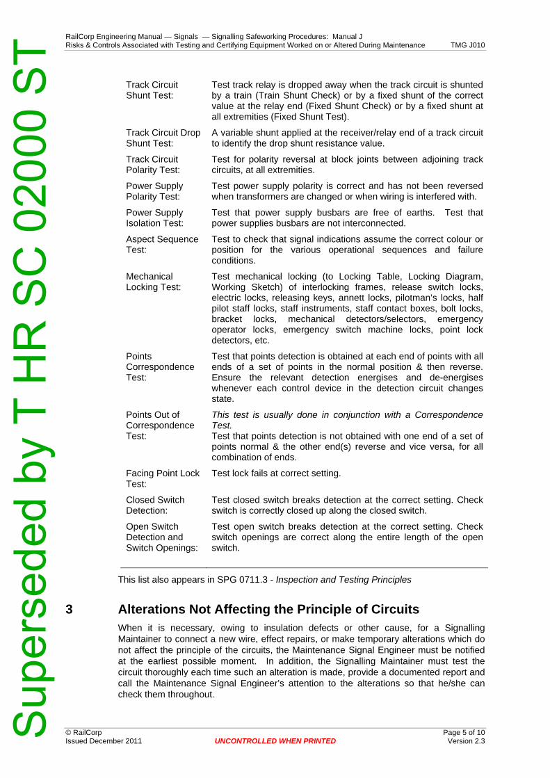
RailCorp Engineering Manual — Signals — Signalling Safeworking Procedures: Manual J Risks & Controls Associated with Testing and Certifying Equipment Worked on or Altered During Maintenance TMG J010
© RailCorp Page 5 of 10 Issued December 2011 UNCONTROLLED WHEN PRINTED Version 2.3
Track Circuit Shunt Test:
Test track relay is dropped away when the track circuit is shunted by a train (Train Shunt Check) or by a fixed shunt of the correct value at the relay end (Fixed Shunt Check) or by a fixed shunt at all extremities (Fixed Shunt Test).
Track Circuit Drop Shunt Test:
A variable shunt applied at the receiver/relay end of a track circuit to identify the drop shunt resistance value.
Track Circuit Polarity Test:
Test for polarity reversal at block joints between adjoining track circuits, at all extremities.
Power Supply Polarity Test:
Test power supply polarity is correct and has not been reversed when transformers are changed or when wiring is interfered with.
Power Supply Isolation Test:
Test that power supply busbars are free of earths. Test that power supplies busbars are not interconnected.
Aspect Sequence Test:
Test to check that signal indications assume the correct colour or position for the various operational sequences and failure conditions.
Mechanical Locking Test:
Test mechanical locking (to Locking Table, Locking Diagram, Working Sketch) of interlocking frames, release switch locks, electric locks, releasing keys, annett locks, pilotman’s locks, half pilot staff locks, staff instruments, staff contact boxes, bolt locks, bracket locks, mechanical detectors/selectors, emergency operator locks, emergency switch machine locks, point lock detectors, etc.
Points Correspondence Test:
Test that points detection is obtained at each end of points with all ends of a set of points in the normal position & then reverse. Ensure the relevant detection energises and de-energises whenever each control device in the detection circuit changes state.
Points Out of Correspondence Test:
This test is usually done in conjunction with a Correspondence Test. Test that points detection is not obtained with one end of a set of points normal & the other end(s) reverse and vice versa, for all combination of ends.
Facing Point Lock Test:
Test lock fails at correct setting.
Closed Switch Detection:
Test closed switch breaks detection at the correct setting. Check switch is correctly closed up along the closed switch.
Open Switch Detection and Switch Openings:
Test open switch breaks detection at the correct setting. Check switch openings are correct along the entire length of the open switch.
This list also appears in SPG 0711.3 - Inspection and Testing Principles
3 Alterations Not Affecting the Principle of Circuits When it is necessary, owing to insulation defects or other cause, for a Signalling Maintainer to connect a new wire, effect repairs, or make temporary alterations which do not affect the principle of the circuits, the Maintenance Signal Engineer must be notified at the earliest possible moment. In addition, the Signalling Maintainer must test the circuit thoroughly each time such an alteration is made, provide a documented report and call the Maintenance Signal Engineer’s attention to the alterations so that he/she can check them throughout.
Sup
erse
ded
by T
HR
SC
020
00 S
T

RailCorp Engineering Manual — Signals — Signalling Safeworking Procedures: Manual J Risks & Controls Associated with Testing and Certifying Equipment Worked on or Altered During Maintenance TMG J010
© RailCorp Page 6 of 10 Issued December 2011 UNCONTROLLED WHEN PRINTED Version 2.3
In the event of any relocation or alteration in the adjustment being necessary on any working contact, special reference of such alteration should be recorded and be brought to the attention of the Maintenance Signal Engineer.
Resistances, excepting track resistances, which are provided in certain portions of the equipment, should not be altered without authority from the Maintenance Signal Engineer unless absolutely necessary to meet an emergency. In such cases the resistances must be replaced as soon as normal conditions are restored.
Resistances in track circuits may be altered as required, care being taken to see that the relays are not receiving more energisation than is necessary for their normal operation. A careful check must be made of the track circuit to ascertain the necessity for the alteration, and, if possible, the cause removed and the resistance restored. The Maintenance Signal Engineer shall be promptly notified of any adjustment or alteration to resistance values. The Track History Card shall be updated to record any alteration.
In an emergency, a suitably accredited Signalling Maintainer may transfer a circuit from a defective contact or terminal to an equivalent spare contact or terminal or transfer a circuit from a defective cable core to a spare cable core provided the following procedure is also followed:
• The circuit is tested to prove that the circuit has not been altered in any way. • The Maintenance Signal Engineer shall be promptly notified of any changes. • Any rearrangement in vital signalling circuits to the existing wiring between
terminals, although there may be no change to the principle of the circuit, and even though the terminals may not be detailed in the existing circuit book, shall constitute a wiring alteration and, other than in emergency, require the prior approval of the Maintenance Signal Engineer.
• Design drawings are required to be brought up to date with any permanent changes; the Maintenance Signal Engineer shall be advised and make suitable arrangements with the Signal Design section.
3.1 Renewal of Signalling Equipment
When it is necessary to renew signalling equipment that has become defective or life expired, the Signalling Maintainer must be aware of the risks involved with the work including an assurance that the equipment being replaced is with an identical item.
Where the replacement item is not exactly identical, authorisation from the Maintenance Signal Engineer in accordance with SPG 0711.9 must be obtained.
4 Alterations Affecting the Principle of Circuits Alterations which affect the principle of the circuits shall be carried out only to approved design alterations as authorised by the Chief Engineer Signals.
A suitably licensed Signal Engineer shall be responsible for implementing and commissioning the alteration in accordance with Standard Specification SPG 0711 and hence shall be the "Commissioning Engineer". Testing and certification shall be carried out by the Commissioning Engineer or an independent, suitably licensed Signal Engineer (who did not install any part of the alteration) as nominated and instructed by the Commissioning Engineer.
Sup
erse
ded
by T
HR
SC
020
00 S
T

RailCorp Engineering Manual — Signals — Signalling Safeworking Procedures: Manual J Risks & Controls Associated with Testing and Certifying Equipment Worked on or Altered During Maintenance TMG J010
© RailCorp Page 7 of 10 Issued December 2011 UNCONTROLLED WHEN PRINTED Version 2.3
5 Relocating or Moving Relay Racks Moving, relocating or temporarily supporting relay racks with operational relays in service should be avoided wherever possible. Whenever it is unavoidable precautions must be taken to ensure that there is no possibility of irregular operation, otherwise all associated circuits are to be disconnected and booked out of use.
Similarly, when any abnormal activity could tilt or turn upside down vital signalling equipment which relies on gravity return, the work must not be carried out while the equipment or affected circuits are in operational service.
6 Authority to Interfere with Working Signalling Circuits Licensed Signal Engineers and suitably licensed Signalling Maintainers are permitted to interfere with vital signalling equipment and working circuits in the performance of their duties, in accordance with RailCorp standards and as approved by relevant Commissioning or Maintenance Signal Engineers.
Signalling personnel are deemed licensed when they have been trained and assessed as competent, have satisfactorily passed the RailCorp 'Licence to Practice' board examination and then hold a current RailCorp Certificate of Competency for their classification. The term 'suitably licensed' refers to the Signalling Maintainer being licensed for the work pertaining. For example, a Signal Electrician is permitted to disconnect electrical signalling in the course of their duties, where other classifications of licensed Signalling Maintainer are prohibited from this task unless appropriately supervised.
Persons who are not licensed in signalling are not to interfere with operational signalling circuits or equipment, nor shall they do anything that affects or could affect the adjustment of operational signalling equipment, except as specifically instructed and under direct and close supervision of suitably licensed Signalling Maintainers or licensed Signal Engineers who shall take responsibility for the work being performed by the non licensed person. This work shall include the removal or insertion of fuses, terminal pins and links in operational signalling circuits or equipment in association with booking apparatus out or into use.
Signalling personnel, including electrical mechanics, graduate engineers and unlicensed signal engineers, who are deemed 'Authorised Persons', may be permitted as directed by a licensed person, to perform limited signalling work as stated on their respective Certificate of Competency and their Permit to Work, with a reduced level of supervision.
Non RailCorp Licensed or Authorised signalling personnel are permitted to perform work in live signalling locations, apparatus and cable routes in accordance with the provisions specified in TMGA 1417 Authorisation of Non-Railcorp Personnel to Carry Out Signalling Works or TMG A1419 Authority to Work on Railcorp Signalling Infrastructure - Permit to Work, limited to the competencies stated on their respective Certificate of Competency.
The statement 'direct and close supervision' requires the supervised person to work in reasonable proximity to the supervising person. Reasonable proximity refers to the supervised works being clearly seen and heard within normal hearing and speaking distance given the ambient noise level. All supervised work shall meet these criteria for reasonable proximity. The use of non-licensed/non-authorised signalling personnel to perform similar duties at remote locations where the criteria of reasonable proximity cannot be met, or where it is necessary to use telephones or radios to communicate is strictly forbidden
Sup
erse
ded
by T
HR
SC
020
00 S
T

RailCorp Engineering Manual — Signals — Signalling Safeworking Procedures: Manual J Risks & Controls Associated with Testing and Certifying Equipment Worked on or Altered During Maintenance TMG J010
© RailCorp Page 8 of 10 Issued December 2011 UNCONTROLLED WHEN PRINTED Version 2.3
Additionally, the work shall be performed by persons competent of doing the work. For example, a relevant trade person shall be required for building, electrical or air conditioning works.
The supervised work shall be commensurate with the licence/authorisation level of the person providing the supervision (see examples below). Suitable instruction shall be provided to the person performing the work to ensure they understand the signalling requirements associated with the work.
Example 1: A suitably Licensed Signalling Maintainer (Signal Electrician) conducting track circuit testing or insulation testing of local equipment tail cables at a signal location, may use a non-licensed person to assist in the removal or insertion of fuses, terminal pins and links in existing operational signalling circuits where it is necessary to complete the work.
Example 2: A suitably Authorised Person (Signal Electrical Installer) may supervise another person who is not an Authorised Person to install wiring within a live signalling location within the limits pertaining to the Authorised Person's Certificate of Competency and Permit to Work.
Example 3: A suitably Authorised Person (Electrical Mechanic) may supervise another person who is not an Authorised Person to perform works such as maintenance of air conditioning systems, fire protection systems, security systems, building structures, etc, that are well clear of operational signalling equipment within a live signalling location.
The above examples are provisional of:
• The person having the applicable trade and other essential competencies • The person having been suitably instructed • The work meets the criteria for reasonable proximity
The practise, where signalling maintenance teams only comprise of a Signal Electrician & a Signal Mechanical person, and the Mechanical Person provides general assistance for electrical testing of signalling (meter readings, holding test leads, observations, etc), is recognised under these provisions and remains permissible. The level of assistance provided shall be at the discretion of the Signal Electrician who shall take responsibility for the entire work.
6.1 New Works and Alterations
Where signalling equipment and/or circuits are disconnected and booked out of use and where the precautions in place together with the inspection and testing activities to be conducted will adequately ensure that only the intended connections, disconnections and adjustments will occur, then non-licensed persons, suitably authorised and experienced, who receive proper instruction, may be used to progress the work on the disconnected signalling equipment and circuits under a level of supervision commensurate with the attendant risks.
The precautions in place, the inspections and tests to be conducted, and the level of supervision are also required to safeguard against:
• The possibility of inadvertent or mistaken interference with working signalling equipment and circuits in the vicinity that are not disconnected and booked out of use.
• The possibility of wiring connections being made inadvertently or mistakenly to the wrong terminals (and then the correct connections being made with separate wiring) and the incorrect wiring being overlooked and left connected in a situation where it would not necessarily be detected in functional testing of the intended alterations. (When carrying out new work and alterations, any incorrect wiring run or wiring incorrectly terminated is to be removed as soon as it is discovered.)
Sup
erse
ded
by T
HR
SC
020
00 S
T
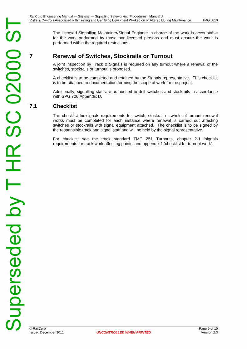
RailCorp Engineering Manual — Signals — Signalling Safeworking Procedures: Manual J Risks & Controls Associated with Testing and Certifying Equipment Worked on or Altered During Maintenance TMG J010
© RailCorp Page 9 of 10 Issued December 2011 UNCONTROLLED WHEN PRINTED Version 2.3
The licensed Signalling Maintainer/Signal Engineer in charge of the work is accountable for the work performed by those non-licensed persons and must ensure the work is performed within the required restrictions.
7 Renewal of Switches, Stockrails or Turnout A joint inspection by Track & Signals is required on any turnout where a renewal of the switches, stockrails or turnout is proposed.
A checklist is to be completed and retained by the Signals representative. This checklist is to be attached to documentation forming the scope of work for the project.
Additionally, signalling staff are authorised to drill switches and stockrails in accordance with SPG 706 Appendix D.
7.1 Checklist The checklist for signals requirements for switch, stockrail or whole of turnout renewal works must be completed for each instance where renewal is carried out affecting switches or stockrails with signal equipment attached. The checklist is to be signed by the responsible track and signal staff and will be held by the signal representative.
For checklist see the track standard TMC 251 Turnouts, chapter 2-1 ‘signals requirements for track work affecting points’ and appendix 1 ‘checklist for turnout work’.
Sup
erse
ded
by T
HR
SC
020
00 S
T
RailCorp Engineering Manual — Signals — Signalling Safeworking Procedures: Manual J Risks & Controls Associated with Testing and Certifying Equipment Worked on or Altered During Maintenance TMG J010
© RailCorp Page 10 of 10 Issued December 2011 UNCONTROLLED WHEN PRINTED Version 2.3
This page has been intentionally left blank
Sup
erse
ded
by T
HR
SC
020
00 S
T
RailCorp Engineering Manual — Signals — Signalling Safeworking Procedures: Manual J Precautions Associated with Renewals Work TMG J011
© RailCorp Page 1 of 8 Issued March 2011 UNCONTROLLED WHEN PRINTED Version 3.2
TMG J011
PRECAUTIONS ASSOCIATED WITH RENEWALS WORK
Version 3.2
Issued March 2011
Document control
Version Date Summary of change 1.0 12 Sep 2005 Replaced SC 00 52 00 11 Like for Like Renewals, Etc 2.0 May 2009 Name changed from ‘Like for Like Renewals’ to ‘Renewals Work’.
Sections changed: 1.1 ‘Overview’ added, 1.2 ‘Like for Like Renewal’ added, & 1.3 ‘General Renewals Work’ added. Ref to MIMS changed to Ellipse. Other minor changes to accommodate SPG 0711.9 procedures
3.0 August 2009 Standard name change and updated in line with SPG 0711.9 3.1 May 2010 Application of TMA 400 format 3.2 March 2011 Applicability changes to Like for Like Renewal section 1.2
Contents 1 Introduction .............................................................................................................................3
1.1 Overview....................................................................................................................3 1.2 Like for Like Renewal ................................................................................................3 1.3 Equipment Replacement which is not Like for Like...................................................3 1.4 General Renewals Work............................................................................................3
2 Relay Change - Plug-in Relays ..............................................................................................3 3 Relay Change - Shelf Relays..................................................................................................4 4 Equipment Change .................................................................................................................5 5 Rewiring ...................................................................................................................................5 6 Transformer Change...............................................................................................................6 7 Modifications to Existing Circuits .........................................................................................6 8 Instructions when Working Near or Interfering With Existing Signalling .........................6
8.1 Isolation from Working Circuits ..................................................................................6 8.2 Mixing of Old and New Circuits .................................................................................6 8.3 Loose Wires or Crimps ..............................................................................................6 8.4 Connection or Disconnection from Vital Circuits .......................................................6 8.5 Interference with Working Circuits, Security of Signalling Locations ........................6 8.6 Wiring Not in Use.......................................................................................................7 8.7 Tagging of Wiring at Termination Points ...................................................................7 8.8 Labelling of Stagework ..............................................................................................7
Sup
erse
ded
by T
HR
SC
020
00 S
T
RailCorp Engineering Manual — Signals — Signalling Safeworking Procedures: Manual J Precautions Associated with Renewals Work TMG J011
© RailCorp Page 2 of 8 Issued March 2011 UNCONTROLLED WHEN PRINTED Version 3.2
8.9 Temporary Wiring ......................................................................................................7 8.10 Spare Wires ...............................................................................................................7 8.11 Equipment Not in Use................................................................................................7 8.12 Insulating the Wire and Equipment Not in Use..........................................................8 8.13 Test Equipment..........................................................................................................8 8.14 Use of Spares or Reuse of Existing Equipment ........................................................8 8.15 Interfacing of New and Existing Work........................................................................8
Sup
erse
ded
by T
HR
SC
020
00 S
T

RailCorp Engineering Manual — Signals — Signalling Safeworking Procedures: Manual J Precautions Associated with Renewals Work TMG J011
© RailCorp Page 3 of 8 Issued March 2011 UNCONTROLLED WHEN PRINTED Version 3.2
1 Introduction 1.1 Overview
Whenever vital signalling equipment is renewed or replaced it shall be done in accordance with the applicable Network Rules and Procedures and the restored equipment shall be tested and certified correct before the apparatus is brought back into use.
The following precautions are to be adhered for the renewal or replacement of signalling equipment including relays, electrical apparatus, trackside equipment, and wiring to ensure that there is no alteration to the circuit, including no change of polarity or adjustment.
In the case of like for like replacement, the work shall be tested and certified by the Signalling Maintainer performing the work, meaning that the Signalling Maintainer is accountable for ensuring that it is correct and that no alteration has occurred.
Where there is any modification to the principle of the circuits or interlocking, a suitably licensed Signal Engineer shall be nominated to commission the alteration using an approved signal design.
1.2 Like for Like Renewal
SPG 0711.9 Like for Like Renewals Procedures shall be used for each like for like renewal of signalling equipment including shelf relays, electrical apparatus and trackside equipment. Where a specific work instruction for the type of renewal is not provided, the Maintenance Signal Engineer shall be consulted.
The procedure shall also apply where items of equipment are temporarily removed, (involving the removal of wiring/cable that connects the equipment to the interlocking), and later reinstated for use. For example, trainstop temporarily removed from track to allow for track work. In these cases, the work shall be treated as Like for Like.
1.3 Equipment Replacement which is not Like for Like
Where an item of vital signalling equipment is required to be replaced with an item which is not the same type and not equivalent in all respects then the matter shall be referred to the Maintenance Signal Engineer who shall determine if the renewal can proceed under the "like for like" process or otherwise it shall be deemed "general renewals work".
1.4 General Renewals Work
Except as provided for in SPG 0711.9 - Like for Like Procedures, all other renewals work will be deemed "general renewals work" which requires supporting documentation including an authorised design, work package, test plans, & work instructions as prescribed in Standard Specification SPG 0711. This work shall be certified by a Commissioning Engineer or a nominated, suitably licensed Signal Engineer.
2 Relay Change - Plug-in Relays This Section is to be read in conjunction with TMG J024 - Vital Signal Relays
The following precautions apply when replacing plug-in relays.
Plug-in relays may be changed over as traffic conditions permit between trains.
Sup
erse
ded
by T
HR
SC
020
00 S
T
RailCorp Engineering Manual — Signals — Signalling Safeworking Procedures: Manual J Precautions Associated with Renewals Work TMG J011
© RailCorp Page 4 of 8 Issued March 2011 UNCONTROLLED WHEN PRINTED Version 3.2
Prior to placing any plug-in relay in service it shall be closely inspected to see that the contacts are aligned correctly and it has not been damaged in transit. The replacement relay shall be checked to be of the same voltage, type, contact configuration, and coding pin index, as the existing relay.
The new relay is to be operationally tested in the plug-in relay test panel, prior to placing into service.
Magnetically latched relays must be driven down before they are placed in circuit.
After changing over, the principal functions controlled by the relay shall be checked to ensure they operate in accordance with the specific circuit design.
If the replaced relay had caused a failure, the change details shall be recorded in Teams III and IFMS failure recording system. Change details for certain plug-in relays (plug-in vane relays, electromechanical or thermal relays, track relays, etc) shall be recorded as prescribed in TMG J024 – Vital Signalling Relays or TMG J025 - Track Circuits as applicable.
3 Relay Change - Shelf Relays This Section applies to all AC and DC shelf relays and is to be read in conjunction with TMG J024 - Vital Signal Relays & SPG 0711.9 – Like for Like Procedures
Shelf relays that become defective or due for replacement must be replaced with a relay type of identical configuration to the relay being replaced. Where this is not practical, the Signalling Maintainer shall consult with the Maintenance Signal Engineer for advice prior to replacing the relay. In this case, the Maintenance Signal Engineer shall ensure that the specific circuit design principles have not been altered and that the replacement relay is treated as a "temporary repair" or otherwise, after obtaining approval from the Principal Engineer Signal Design, arrange for the affected circuit documentation to be updated.
Note:
It is permissible to replace a double element AC line relay with a single element type and vice versa provided due care is taken to ensure that local and control coils are correctly bridged in parallel for double element relays.
The replacement relay is to be examined and bench tested for correct operation and checked that it is of the same type and contact configuration as the one to be replaced and as shown in the circuit book prior to placing into service. The relay must be sealed and the seal must not be broken.
The replacement of shelf type relays is treated as safety-critical work and must be carried through by a Signalling Maintainer using the utmost care. Transfer to another person part way through is not permitted.
The procedure as prescribed in SPG 0711.9 - Like for Like Procedures shall be strictly followed for the replacement of shelf relays.
Whenever track relays are replaced, the Signalling Maintainer shall ensure that the shunt value is within the permissible range of values for the type of track and that the local coil voltage and current and track coil voltage and current are correctly adjusted.
When any DC shelf-mounted relay or DC standard 'B' size plug-in relay is changed the "pick-up", "drop-away" and "working" currents of the new relay shall be tested.
The change details shall be recorded in the form SF J024/B by the Signalling Maintainer and forward to the Maintenance Signal Engineer for recording as prescribed in TMG J024
Sup
erse
ded
by T
HR
SC
020
00 S
T

RailCorp Engineering Manual — Signals — Signalling Safeworking Procedures: Manual J Precautions Associated with Renewals Work TMG J011
© RailCorp Page 5 of 8 Issued March 2011 UNCONTROLLED WHEN PRINTED Version 3.2
– Vital Signalling Relays. The relay records or database shall be updated to reflect the change. Should the replacement be due to a relay failure, then details shall also be recorded in Teams III and IFMS failure recording system.
4 Equipment Change This Section is to be read in conjunction with SPG 0711.9 – Like for Like Procedures
The following precautions apply to the renewal of electrical signalling apparatus.
The replacement equipment is firstly to be inspected and tested to be the correct type and not defective.
If contacts are to be changed they are to be changed one contact at a time by the Signalling Maintainer.
If a contact carrier, circuit controller or other electrical equipment is required to be changed which requires the removal and reconnection of wires, then the provisions and procedures as prescribed in SPG 0711.9 - Like for Like Procedures shall be observed.
Caution must be taken when renewing mechanical equipment, including rodding, cranks, etc, to ensure that the operation of such apparatus is not altered by the renewed components. Where the renewal alters the configuration of interlocking equipment, it shall be certified to be accordance with an approved signal design by a suitably licensed Signal Engineer.
Adjustable equipment shall be tested in circuit (or insitu) for correct adjustment.
Refer also to Section 6 for change of transformers.
5 Rewiring This Section is to be read in conjunction with TMG J012 - Repair/Replacement of Signalling Wires & SPG 0711.9 – Like for Like Procedures
Rewiring of working circuits may be carried out by a Signalling Maintainer one wire at a time to the procedures specified under TMG J012 Repair/Replacement of Signalling Wires.
If more than one wire of the existing circuits is to be disconnected prior to the reconnection of the replacement wires, then the work shall be planned so that a suitably licensed Signal Engineer, or other suitably accredited, competent person, is in attendance to carry out circuit tests, and restore the apparatus into use.
If single wire cables are to be replaced by multi-core cables then a suitably licensed Signal Engineer, or other suitably accredited, competent person, shall carry out the tests and restore the apparatus into use.
Tests shall include pre and post polarity tests where there is any possibility of reversal of power supply wiring or of wiring in polarity sensitive circuits eg; track circuits, paired detector circuits.
Rewiring like-for-like on other than a one-for-one changeover basis requires the prior approval of the Maintenance Signal Engineer. Planned rewiring on other then a direct like-for-like basis requires certification on a circuit diagram by a suitably licensed Signal Engineer.
Sup
erse
ded
by T
HR
SC
020
00 S
T

RailCorp Engineering Manual — Signals — Signalling Safeworking Procedures: Manual J Precautions Associated with Renewals Work TMG J011
© RailCorp Page 6 of 8 Issued March 2011 UNCONTROLLED WHEN PRINTED Version 3.2
6 Transformer Change When a transformer is changed there is a possibility that the polarity of the output voltage will be reversed due to differences in the internal wiring of the transformers.
When power supply transformers or track circuit transformers are changed, test the polarity before and after the change to ensure that it has not been reversed.
7 Modifications to Existing Circuits These shall comply with the requirements in Standard Specification SPG 0711.
8 Instructions when Working Near or Interfering With Existing Signalling Below are precautions that shall be adhered when involved in interfering with existing circuits or when working near existing circuits.
8.1 Isolation from Working Circuits
Wires and equipment, de-commissioned from use, or not yet commissioned into use, shall not be connected at any point to working signalling circuits or power supplies and must be secured against and insulated from any possible metallic contact with working circuits.
8.2 Mixing of Old and New Circuits
If new wiring is to tap into old circuits none of the new wiring is to be connected into the existing working circuit before commissioning.
8.3 Loose Wires or Crimps
Loose wires with exposed conductors or with exposed crimps or lugs etc shall not be left unterminated near working circuits or equipment. They shall be clearly labelled and have their ends secured and insulated to prevent contact with one another or with any other equipment.
8.4 Connection or Disconnection from Vital Circuits
For New Works and Alterations, wires or equipment shall only be connected into or disconnected from vital signalling circuits when the affected signalling apparatus is disconnected and formally booked out of use.
8.5 Interference with Working Circuits, Security of Signalling Locations
All precautions shall be taken to ensure that working circuits cannot be mistakenly interfered with, accidentally damaged, or shorted out by tools, loose relay nuts, washers, bits of wire, etc.
All vital equipment and locations shall be fitted with locks and be locked when unattended.
Before closing up equipment or locations, persons shall check that everything is in order and properly connected and that nothing has been left loose, foul of standard clearances, or in a potentially unsafe condition.
Sup
erse
ded
by T
HR
SC
020
00 S
T

RailCorp Engineering Manual — Signals — Signalling Safeworking Procedures: Manual J Precautions Associated with Renewals Work TMG J011
© RailCorp Page 7 of 8 Issued March 2011 UNCONTROLLED WHEN PRINTED Version 3.2
Only persons who are properly instructed and authorised by the Maintenance Signal Engineer or Commissioning Engineer are permitted to work without close supervision (by suitably qualified staff) in equipment locations and relay rooms.
Only persons who are suitably licensed or closely supervised by a suitably licensed person are permitted to interfere with existing signalling circuits or equipment.
8.6 Wiring Not in Use
In working locations any wiring or equipment which is not in use for signalling shall be distinctively evident as such and shall be clearly and adequately labelled accordingly. It shall be kept isolated from any power supply except as necessary under supervised use.
8.7 Tagging of Wiring at Termination Points
At the termination point where new wiring is to be connected to working circuits, or where old wiring is to be disconnected from working circuits, the wire shall be fitted with a tag clearly identifying the circuit and terminal to which it applies and the terminal to which it runs; the other end of any such wire it is to be similarly tagged.
8.8 Labelling of Stagework
Wiring to be commissioned or de-commissioned in stages shall be clearly labelled as to what stage it is to be commissioned or de-commissioned. On changeover, the stage labelling shall be removed, the correct labelling applied and the arrangements made obviously permanent.
8.9 Temporary Wiring
Temporary stagework wiring is to be of a distinctive colour with a different colour for each stage.
Temporary wiring for testing purposes is to be of a distinctive type and colour.
The distinguishing colours for temporary wiring should be documented and displayed in the location concerned.
The use of temporary wiring must be strictly controlled and must be removed as soon as it has served its purpose and prior to through testing. All temporary wiring shall be documented for this purpose and records kept by the Maintenance Signal Engineer.
8.10 Spare Wires
Spare wires in equipment locations shall be properly terminated on spare terminals on termination racks; spare wires within trackside apparatus shall have the ends insulated, if there are no spare terminals available.
8.11 Equipment Not in Use
Equipment not in use and disconnected from the interlocking shall be securely open circuited and labelled accordingly.
It shall not be sufficient to only remove a fuse or open a link or remove a signal lamp etc ie, situations where someone could mistakenly insert a fuse or connect a link or insert a lamp etc and cause a potentially unsafe situation. The equipment shall be securely open circuited in two places where practical, and measures applied to prevent accidental or mistaken connection at both places.
Sup
erse
ded
by T
HR
SC
020
00 S
T

RailCorp Engineering Manual — Signals — Signalling Safeworking Procedures: Manual J Precautions Associated with Renewals Work TMG J011
© RailCorp Page 8 of 8 Issued March 2011 UNCONTROLLED WHEN PRINTED Version 3.2
8.12 Insulating the Wire and Equipment Not in Use
Where insulation of unconnected wiring or equipment out of use is required, a secure method shall be used.
Insulating tape or adhesive devices shall not be reused, new insulating tape etc., is required on each occasion. Approved closed and pre-insulated connectors properly crimped to wires shall be used where applicable.
Adhesive insulating tape should not be used directly on prepared conductor ends or on terminal lugs or pins etc, that are intended to be brought into use subsequently, as the adhesive may cause unreliable contact resistance.
The insulation method and application shall be checked to be effective.
8.13 Test Equipment
Approved test equipment only shall be connected to signalling circuits and equipment.
Test lamps shall not be used as they may provide a significant leakage path for circuit currents.
Test equipment shall be subject to calibration checks taken and recorded at appropriate intervals.
Electrical test instruments shall have insulated prods, etc.
8.14 Use of Spares or Reuse of Existing Equipment
Use of spares or reuse of redundant or existing equipment in New and Altered Works shall require the agreement of the Maintenance Signal Engineer.
All spares, redundant or existing wires, cable cores, contacts or other items of equipment which are to be utilised in new circuits or in altered parts of existing circuits must first be inspected and tested to ensure that:
• They are spare without any connection at any point with other conductors, contacts, power supplies, or other equipment.
• Their condition complies with the required standard. • They are properly insulated without any leak or potential leak of current to or from
earth or other circuits.
Special attention must be paid to ensure that terminals are not connected together by jumper bars or other strapping.
The results of the wire count, bell continuity test and insulation tests of the new circuit or altered parts of existing circuits, inclusive of the spare or reused items, shall be recorded and certified.
8.15 Interfacing of New and Existing Work
Where new or altered work is to interface with existing vital signalling, the Commissioning Engineer with the Signal Design Engineer shall together satisfy themselves of the accuracy of existing signalling plans and circuit diagrams to the as-built situation, in consultation with the Maintenance Signal Engineer. If there is reasonable cause to doubt that they are accurate then the existing arrangements, which are to be altered to connect with the new arrangements, shall be tested and certified.
Sup
erse
ded
by T
HR
SC
020
00 S
T

RailCorp Engineering Manual — Signals — Signalling Safeworking Procedures: Manual J Repair/Replacement of Signalling Wires TMG J012
© RailCorp Page 1 of 8 Issued April 2011 UNCONTROLLED WHEN PRINTED Version 1.3
TMG J012
REPAIR/REPLACEMENT OF SIGNALLING WIRES
Version 1.3
Issued April 2011
Document control
Version Date Summary of change
1.0 September 2005 Replaced SC 00 52 00 12 SI Repair/Replacement of Signalling Wires
1.1 May 2010 Application of TMA 400 format
1.2 July 2010 Added section 5.4 Additional testing procedure following cable damage Added section 7 Signalling Data Communication Links
1.3 April 2011 Clarify requirements for Additional Testing Procedure Following Cable Damage in 5.4
Contents 1 Emergency Repair/Replacement Procedures ......................................................................2 2 Single Wire Replacement .......................................................................................................2 3 Single Wire Repair ..................................................................................................................4 4 Track Circuit Wires-Repair, Replacement ............................................................................4 5 Multicore Cables - Repair, Replacement ..............................................................................4
5.1 Transfer to a spare cable core...................................................................................4 5.2 Jointing of broken cores.............................................................................................5 5.3 Replacement with another multicore cable................................................................6 5.4 Additional testing procedure following cable damage ...............................................7
6 Multiple Wires-Repair, Replacement.....................................................................................7 7 Signalling Data Communication Links .................................................................................7
7.1 Transfer to a spare copper cable pair........................................................................7 7.2 Transfer to a spare optical fibre conductor ................................................................7
Sup
erse
ded
by T
HR
SC
020
00 S
T

RailCorp Engineering Manual — Signals — Signalling Safeworking Procedures: Manual J Repair/Replacement of Signalling Wires TMG J012
© RailCorp Page 2 of 8 Issued April 2011 UNCONTROLLED WHEN PRINTED Version 1.3
1 Emergency Repair/Replacement Procedures Whenever wires are broken or defective or otherwise in need of repair or replacement, extreme care is necessary to ensure that wires are not cross connected or circuits interconnected.
The following emergency repair/replacement procedures for signalling wires are to be followed.
2 Single Wire Replacement If a new wire is needed to replace a single broken or defective wire the Signalling Maintainer shall:
a) Advise the signaller and book out of use the apparatus controlled by the affected circuit.
b) Identify and label both terminal ends of the broken or defective wire; hand trace where possible; ensure that there are no intermediate terminals or contacts; and ensure the wiring is in accordance with the circuit books. With external cables ensure that the cable does not go through any intermediate location.
c) Run the new wire and prepare ends for changeover. Keep ends clear and insulated from working circuits. Label ends with identity of terminal to which they will be connected.
d) Disconnect the affected circuits.
e) Disconnect the broken or defective wire and immediately connect the new wire, one end at a time. Cut back all ends of the broken or defective wire and carefully remove the wire. If the redundant wire cannot be removed then cut, turn back and insulate all ends securely (including ends at the break) and label with tags as "Defective".
f) Insulation test the new circuit wire to earth.
g) Test as required (see Note below).
h) Re-connect the affected circuit.
i) Advise the signaller and restore the apparatus into use.
j) Promptly advise the Signal Engineer and certify the repairs by submitting a Detailed Report advising details of the repair. The Signal Engineer shall check and assure themselves that the work was performed correctly.
Note:
If the identity of the terminal ends of the broken wire cannot be established with absolute certainty, then the testing shall be extended to include
tracing and verifying the existing wiring to the circuit book to one clear series contact, fuse or link each side of the new wire
or
strap and function testing to one clear series contact, fuse or link inclusive each side of the new wire.
Sup
erse
ded
by T
HR
SC
020
00 S
T

RailCorp Engineering Manual — Signals — Signalling Safeworking Procedures: Manual J Repair/Replacement of Signalling Wires TMG J012
[REFER TO ACCOMPANYING ILLUSTRATION RE: NECESSITY TO CORRECTLY IDENTIFY THE TERMINAL ENDS OF A DEFECTIVE WIRE]
Note:
Throughout the process ensure there is no possibility of there being a disconnected wire with one end loose and uninsulated with the other end connected to, or able to come into contact with, any “live” circuit elements.
Illustration Of Necessity To Correctly Identify The Terminal Ends Of ADefective Wire And Change Over Onto Those Same Terminals
4 7 3
A
5
B *
7
C
6
ACR
X B YXYR
A
5
B
1
C
6
ACR
X *B YXYR
ORStrap and function test to one contact clear of each point of connection (as shown in the circuit book)
ORTrace and verify wires on the other side of the contact at each point of connection
Change over at C6 point
Change over at B7 armature (suppose ACR relay picks up)
Strap and function test B7 and C6
EITHERHandtrace defective wire end to end
The above precautions apply whether the defective wire is connected to contacts, fuses or links. When carrying out circuitmodifications the same potential for wrongly interconnecting circuits exists if contact terminals, fuses or links are wronglyidentified.
ARC circuit and contact B7 as shown in the circuit book ARC circuit and contact B7 as it actually is
A
5
B
1
C
6
ACR
X
4
B
7
Y
3
XYR
A
5
B
1
C
6
ACR
X *B YXYR
A
5
B
1
C
6
ACR
4 7 3
X *B YXYR
F
F
A
5
B
1
C
6
ACR
4 7 3
X *B YXYR
F
F
T
T
A
5
B
1
C
6
ACR
4 7 3
X *B YXYR
F
F
T
T
A
5
B
1
C
6
ACR
4 7 3
X *B YXYR
FFT
F
4 7 3
A
5
B
1
C
6
ACR
X B YXYR
4 9 3 4 7 3
Run new wire to replace wire between B7 and C6
Suppose ACR circuit has failed and there is no positive voltage on the coil. Suppose in checking back through thecircuit as shown in the circuit book the first positive voltage is found on B7 armature and it is checked that there isno continuity between B7 armature and C6 point. Suppose the maintainer assumes that the wire between B7armature and C6 point is defective, open circuit somewhere along its length, and decides to replace the wire.
At this stage the test seem to indicate that the failure has been rectified, but in fact two separate circuits has beenwrongly interconnected. The following inspection and test are also necessary to verify the correct repair.
© RailCorp Page 3 of 8 Issued April 2011 UNCONTROLLED WHEN PRINTED Version 1.3 Sup
erse
ded
by T
HR
SC
020
00 S
T
RailCorp Engineering Manual — Signals — Signalling Safeworking Procedures: Manual J Repair/Replacement of Signalling Wires TMG J012
© RailCorp Page 4 of 8 Issued April 2011 UNCONTROLLED WHEN PRINTED Version 1.3
3 Single Wire Repair If a signalling failure is traced to a single broken wire or cable, the Signalling Maintainer shall correctly identify the ends of the wire and the circuit to which the wire belongs and, if it is obvious that only one wire is broken, the Signalling Maintainer shall join the broken wire ends together with a reliable, secure connection after otherwise disconnecting the circuit concerned.
Joins in wires shall be properly insulated and the Signalling Maintainer shall insulation test to earth joints made in external wires.
The Signalling Maintainer shall reconnect and test the circuit and ensure that the failure is rectified.
4 Track Circuit Wires-Repair, Replacement Should two or more track circuit leads to a location be broken or in need of replacement then the Signalling Maintainer shall follow the same procedure to that in Sections 2 and 3 changing over one wire at a time and shall include the following.
The Signalling Maintainer shall ensure that the wires have not been cross connected, test that the track relay of the track circuit concerned de-energises with a shunt across the rails, and carry out a polarity test and a shunt test on the adjacent track circuit at the location on the lines affected.
Where cut tracks are involved, the Signalling Maintainer shall test that a shunt across the rails of the adjacent track circuit removes the voltage from the rails of the cut track.
5 Multicore Cables - Repair, Replacement Should cores in a multicore cable be broken or defective then the Signalling Maintainer shall follow the same procedure to that in Sections 2 and 3, changing over one wire at a time, and shall also observe the following.
5.1 Transfer to a spare cable core
Follow the same procedure to that in Sections 2 and 3, as applicable, and also observe the following:
Should a core of a multicore cable used in a signalling circuit become open circuit or defective then replace the cable core concerned with a spare core of the same cable which is not defective, if available.
Identify and open the cable termination link at each end of the defective cable core after verifying the cable core number to the terminal and after verifying that the circuit connected to the cable termination link at each end is the same circuit.
Test the cable core identified to be the defective core. Fit the defective cable core with labels marked "Defective" at both termination ends. Open the respective cable termination link at each end and disconnect the defective cable core from the link terminal. Cut all ends cleanly off, turn back and insulate.
Sup
erse
ded
by T
HR
SC
020
00 S
T

RailCorp Engineering Manual — Signals — Signalling Safeworking Procedures: Manual J Repair/Replacement of Signalling Wires TMG J012
Figure 1 - Transferring a Circuit from a defective cable Core to Spare Cable Core
Check the circuit book to ensure that the cable is directly connected between the locations housing the cable links and that there are no intermediate terminals.
Continuity test the spare cable core selected using a separate spare cable core or the sheath as a test return wire, and also insulation test the selected spare to earth, to sheath and to other spare cores.
Transfer the circuit wire at each end from the cable termination link for the defective cable core to the cable termination link for the selected spare cable core.
Function test the circuit by opening and closing the link at each end in turn and observing the circuit function energise and de-energise accordingly. Connect a voltmeter across the circuit function and check that the voltage returns from the correct voltage to zero when the circuit is opened.
When more than one cable core is defective and more then one spare cable core is involved, close the cable termination links at each end for each circuit, one cable core at a time, and function test each circuit over the respective cable core and termination links prior to closing the links for the next cable core.
The Maintenance Signal Engineer shall be advised and shall arrange for the maintenance documentation to be updated.
5.2 Jointing of broken cores
Follow the same procedure to that in Sections 2 and 3, as applicable, and also observe the following.
Where cores in a multicore cable have been broken and it is intended to rejoin the broken cores then identify and label the cores at the break and at the immediate terminal ends, and identify the circuit to which each cable core belongs.
Open the cable termination links of the defective cores at the immediate terminal ends. Conduct a continuity test between these corresponding terminations (at each end) to further check that there is no continuity because of the break.
© RailCorp Page 5 of 8 Issued April 2011 UNCONTROLLED WHEN PRINTED Version 1.3 Sup
erse
ded
by T
HR
SC
020
00 S
T

RailCorp Engineering Manual — Signals — Signalling Safeworking Procedures: Manual J Repair/Replacement of Signalling Wires TMG J012
© RailCorp Page 6 of 8 Issued April 2011 UNCONTROLLED WHEN PRINTED Version 1.3
Joint the corresponding ends at the break of each of the cable cores and carry out a continuity test on each jointed cable core from the cable termination link to the corresponding cable termination link at the other end.
Then carry out an insulation test on the jointed cable cores to earth, to sheath, to one another and to any spare cores in the cable.
Function test each circuit by closing and opening the link at each end in turn and observing the circuit function energise and de-energise accordingly. Connect a voltmeter across the circuit function and check that the voltage returns from the correct voltage to zero when the circuit is opened.
Close the cable termination links at each end for each circuit, one cable core at a time, and function test each circuit over the respective cable core and termination links prior to closing the links for the next cable core.
5.3 Replacement with another multicore cable
Follow the same procedure to that in Sections 2 and 3, as applicable, and also observe the following.
Where a multicore cable is damaged or defective and is being replaced with another multicore cable then open the cable termination links at the immediate terminal ends of the defective multicore cable, and check the cable core numbers to be connected to the corresponding cable link terminal numbers at each end, and check that the circuit connected to the corresponding cable link terminals at both ends is the same circuit, and in accordance with the circuit book.
Disconnect the defective multicore cable and connect the replacement multicore cable, each cable core number corresponding to the cable link terminal number the same as the cable replaced. Carry out a continuity test and an insulation test on the cable cores as above.
Function test each circuit by opening and closing the link at each end in turn and observing the circuit function energise and de-energise accordingly. Connect a voltmeter across the circuit function and check that the voltage returns from the correct voltage to zero when the circuit is opened.
Close the cable termination links at each end for each circuit, one cable core at a time, and function test each circuit over the respective cable core and termination links prior to closing the links for the next cable core.
Sup
erse
ded
by T
HR
SC
020
00 S
T
RailCorp Engineering Manual — Signals — Signalling Safeworking Procedures: Manual J Repair/Replacement of Signalling Wires TMG J012
© RailCorp Page 7 of 8 Issued April 2011 UNCONTROLLED WHEN PRINTED Version 1.3
5.4 Additional testing procedure following cable damage
Where multicore cables are damaged by activities similar to excavation works or other earth works, there becomes a risk that the insulation between the conductors may also become damaged, providing a potential for short circuit current flow for a sustained period which may lead to deformed Q relay contacts.
Where this is the case, in addition to the preceding requirements, a licensed Signal Engineer shall be notified to consider the potential for sustained (exceeding one hour) short circuit current flow. If the cable is determined to be at risk, additional testing of all relay contacts in the affected circuit(s), on the fuse/supply side of the damaged cable, shall be conducted by either one of the following two methods:
1. Test the affected relay in a Relay Test Panel to ensure all contacts operate (open and close) in accordance with their configuration type.
Or
2. Circuit Function Test - functionally operate the affected relay in the circuit to ensure it effectively operates the circuit function as designed.
6 Multiple Wires-Repair, Replacement Should a number of single wires or multicore cables be broken then follow the same procedure to that above in Sections 2, 3 and 5, changing over one wire at a time, with the following exception.
A Signal Engineer, or other suitably accredited, competent person, shall test and certify the repairs prior to the apparatus being restored into use.
7 Signalling Data Communication Links Data communication links are utilised to connect RailCorp Microlok systems, Solid State Interlocking systems, Dupline, Kingfisher and SCADA telemetries, etc. These links consist of either copper communication type cables or optical fibre conductors.
7.1 Transfer to a spare copper cable pair
Where it has become necessary to initiate a change-over to a spare pair in a copper communication type cable, the Signalling Maintainer shall firstly establish the logically correct pair at both ends and then conduct an end-to-end continuity test by approved testing means, prior to certifying the operational signalling apparatus back into use.
7.2 Transfer to a spare optical fibre conductor
Where it has become necessary to initiate a change-over to a spare optical fibre conductor, the Signalling Maintainer shall firstly establish the logically correct fibre at both ends and then conduct an end-to-end continuity test by approved testing means, prior to certifying the operational signalling apparatus back into use.
Sup
erse
ded
by T
HR
SC
020
00 S
T
RailCorp Engineering Manual — Signals — Signalling Safeworking Procedures: Manual J Repair/Replacement of Signalling Wires TMG J012
© RailCorp Page 8 of 8 Issued April 2011 UNCONTROLLED WHEN PRINTED Version 1.3
This page has been intentionally left blank
Sup
erse
ded
by T
HR
SC
020
00 S
T

RailCorp Engineering Manual — Signals — Signalling Safeworking Procedures: Manual J Field Paralleling of Signalling Contacts TMG J013
© RailCorp Page 1 of 2 Issued May 2010 UNCONTROLLED WHEN PRINTED Version 1.1
TMG J013
FIELD PARALLELING OF SIGNALLING CONTACTS
Version 1.1
Issued May 2010
Document control
Version Date Summary of change 1.0 September 2005 Replaced SC 00 52 00 13 SI Field Paralleling of Signalling
Contacts. 1.1 May 2010 Application of TMA 400 format
Contents 1 Introduction .............................................................................................................................2
Sup
erse
ded
by T
HR
SC
020
00 S
T

RailCorp Engineering Manual — Signals — Signalling Safeworking Procedures: Manual J Field Paralleling of Signalling Contacts TMG J013
© RailCorp Page 2 of 2 Issued May 2010 UNCONTROLLED WHEN PRINTED Version 1.1
1 Introduction Signalling Maintainers may connect spare contacts of signalling trackside equipment in parallel with existing contacts (of the same type and setting) in a given circuit on the authority of the Maintenance Signal Engineer, provided that the additional wiring is run directly from the terminals of the existing contact in circuit to the terminals of the spare contact, and is not run to or from other circuit terminals. It is not necessary that an approved design be issued for this, however, the Maintenance Signal Engineer must authorise this change and arrange for the circuit books to be updated.
Each additional wire (two per contact) shall be fitted with beads labelled ‘PC’ or otherwise securely labelled as a ‘parallel contact’ wire.
The Signalling Maintainer must test the parallel pair in circuit before allowing the additional contact to be used in service for the running of trains. (eg: with the circuit energised over both contacts closed, check that the adjacent series contact either side of the parallel pair de-energies and re-energises the circuit function when each is opened and closed in turn; then check that it takes both of the parallel contacts to be open before the circuit will de-energise and that either one closed will energise the circuit).
When contacts are paralleled in the field the existing local circuit books are to be marked with the amendment by the Signalling Maintainer who is to sign and date the sheet next to the amendment.
Contacts in parallel can improve reliability by reducing the series contact resistance, and by helping maintain a low resistance under conditions that cause contacts to vibrate.
It can be also advantageous for maintenance if the contacts of trackside apparatus which require cleaning and tension checking are paralleled; if the contact is closed the tension and cleaning could still be checked one contact at a time without the risk of changing signal aspects in the face of trains. (Otherwise such closed contacts are only to be broken during maintenance when there are no trains approaching the signals that would be affected or else they are to be maintained when the contacts are in their open position. Closed normal contacts of train stops or semaphore signals at stop are similarly not to be broken with a train approaching the signal as, although signal aspects would not be changed, approach locking would be applied).
Reliable, low contact resistance is particularly important for input circuits to SSI trackside TFM modules which operate over very low voltages (5 volt) and use a coded circuit current. Loss of voltage or code through high or varying contact resistance can cause the TFM module to shut down.
Sup
erse
ded
by T
HR
SC
020
00 S
T

RailCorp Engineering Manual — Signals — Signalling Safeworking Procedures: Manual J Document Control of Signal Plans and Circuit Books IssuEd to the Field TMG J014
© RailCorp Page 1 of 8 Issued May 2010 UNCONTROLLED WHEN PRINTED Version 1.1
TMG J014
DOCUMENT CONTROL OF SIGNAL PLANS AND CIRCUIT BOOKS ISSUED
TO THE FIELD
Version 1.1
Issued May 2010
Document control
Version Date Summary of change 1.0 September 2005 Replaced SC 00 52 00 14 SI Document Control of Signal Plans
and Circuit Books Issued to the Field 1.1 May 2010 Application of TMA 400 format
Contents 1 Introduction .............................................................................................................................2 2 Configuration Control.............................................................................................................2 3 Document Control...................................................................................................................2
3.1 General ......................................................................................................................2 3.2 Particular Responsibilities: Maintenance Signal Engineer ........................................3 3.3 Particular Responsibilities: The Project Engineer .....................................................4 3.4 Particular Responsibilities: The Test Engineer (Commissioning
Engineer) ...................................................................................................................5 3.5 Signalling Maintainer’s Responsibilities (and Copy Holders Generally)....................5
Sup
erse
ded
by T
HR
SC
020
00 S
T
RailCorp Engineering Manual — Signals — Signalling Safeworking Procedures: Manual J Document Control of Signal Plans and Circuit Books IssuEd to the Field TMG J014
© RailCorp Page 2 of 8 Issued May 2010 UNCONTROLLED WHEN PRINTED Version 1.1
1 Introduction The purpose of this procedure is to set out the responsibilities and requirements for document control of signal plans and circuit books issued to the field.
The signal plans and circuit books referred to in this procedure include:
• Track Plans and Working Sketches, or combined Signalling Plans • Track Insulation Plans (track bonding plans) • Circuit Diagrams • Circuit Books • Locking Tables, • Locking Diagrams, • Lever Nameplates, • Modification sheets • Control Tables (SSI Installations) • Detailed Site Survey Drawings
2 Configuration Control Other then for like-for-like replacement for maintenance purposes, other specified exceptions, or specially authorised cases, the working signalling equipment and circuits are not to be altered, nor new signalling equipment or circuits commissioned into use, except in accordance with approved designs.
The changes are to be inspected and tested and the design drawings certified by suitably accredited signalling personnel. The masters shall be updated and amended drawings issued to replace out of date copies.
3 Document Control 3.1 General
All persons given a controlled copy of a signal plan or circuit book for their work are to treat it as a valuable document entrusted to their care. Such persons are called “Copy Holders”. Copy Holders may be responsible for one or more copies of the signal plan or circuit book.
All involved with the production, installation, maintenance, and use of signal plans and circuit books have a responsibility for ensuring that the drawings accurately record and correspond to the requirements and/or to the as-built status, as applicable, and they are to promptly advise any discrepancies and arrange to have them corrected without delay. All copy holders shall ensure that they have the latest version of control documents.
All persons with nominated responsibilities under these procedures are to be able to account for all controlled copies of signal plans and circuit books issued to them and, through them, to their subordinates.
Controlling officers of persons with nominated responsibilities under these procedures have a responsibility to satisfy themselves that the procedures are being followed.
Should the persons with the nominated responsibilities be off duty on sick leave, transfer to other jobs, resign or otherwise be unavailable, the controlling officers are to ensure that those responsibilities are appropriately reassigned and carried out.
Sup
erse
ded
by T
HR
SC
020
00 S
T
RailCorp Engineering Manual — Signals — Signalling Safeworking Procedures: Manual J Document Control of Signal Plans and Circuit Books IssuEd to the Field TMG J014
© RailCorp Page 3 of 8 Issued May 2010 UNCONTROLLED WHEN PRINTED Version 1.1
Transmittal notices, on standard “Memo of Document Exchange” forms, are to be included with the despatch of signal plans and for circuit books and the recipient must acknowledge receipt on the transmittal notice and promptly forward a copy back to the sender.
For project works, the requirements of RailCorp specification SPG 0703 “Signalling Documentation and Drawings” are to be complied with as well as RailCorp IMS procedures C15P02 “Document Control” and W45P02 “Finalise Archive Project Documentation”. Where approved Configuration Management Plans (CMP) cover particular signal plans and circuit books then the requirements of the CMP shall be complied with.
3.2 Particular Responsibilities: Maintenance Signal Engineer
The Maintenance Signal Engineer, for his/her area of responsibility, is responsible for:
a) Ensuring that, (except for like-for-like renewals and repairs, other specified exceptions and specially authorised cases) there are no changes to working signalling equipment and circuits without the approved signal plans and circuit books for the alterations.
b) Determining the allocation of controlled copies of signal plans and circuit books for maintenance personnel, and arranging the publication, issue and distribution of the required copies, updated to current arrangements.
c) Maintaining an effective document control system for all the field Maintenance copies of signal plans and circuit books. Checking the field copies versions against the master listing every 12 months and whenever needed. Recording details of copies destroyed.
d) Promptly advising Controlling Officers and arranging for changes to the signal plans and circuit books that are necessary for the correction of any discrepancies found in controlled copies of signal plans and circuit books or arising from maintenance changes due to like-for-like repairs, etc., (eg. cable core numbers, contact or terminal numbers changing because of defective cable cores, contacts or terminals, field parallelling of contacts or terminals) Obtaining acknowledgment of receipt of advice and following up that the corrections have been done by the Signal Design office within a reasonable time.
e) Marking up and signing (preferably in red pen) the Maintenance Signal Engineer’s copies with the corrections required, where such drawing correction is the obvious remedy to a discrepancy with the “as-built” installation, while waiting for updated copies.
f) Booking out of use any vital signalling equipment or circuit which is not in accordance with the signal plans or circuit books if there is any doubt about the integrity of the particular signalling equipment or circuit.
g) Promptly updating the Maintenance Signal Engineer’s office copies of signal plans and circuit books to the latest copies issued and received, and destroying the superseded copies.
h) Issuing the amended copies to the district staff responsible for them within one week of receipt and following up that they have updated their copies and destroyed the superseded copies.
Sup
erse
ded
by T
HR
SC
020
00 S
T

RailCorp Engineering Manual — Signals — Signalling Safeworking Procedures: Manual J Document Control of Signal Plans and Circuit Books IssuEd to the Field TMG J014
© RailCorp Page 4 of 8 Issued May 2010 UNCONTROLLED WHEN PRINTED Version 1.1
Note:
Where new works or alterations are being carried out, refer also to the responsibilities nominated under 'Project Engineer' and ‘Test Engineer’.
3.3 Particular Responsibilities: The Project Engineer
Refer also to RailCorp specification SPG 0703 and RailCorp IMS procedures C15P02 and W45P02.
The Project Engineer (the person carrying out the role of Engineer In Charge of the installation of the works) is responsible for:
a) Liaising with the Signal Design Engineer and agreeing on the number and distribution of copies of signal plans and circuit books for the construction phase of new and altered works.
b) Maintaining an effective document control system for all copies of signal plans and circuit books (including Modification Instruction Forms) issued to and received by the project staff including those copies of signal plans and circuit books (including Modification Instruction Forms) that the Test Engineer has accepted responsibility for.
c) Complying with the practices and procedures set out in standard Specifications in relation to signal plans and circuit books for new works and alterations.
d) Ensuring the delivery and receipt of any signal plans and circuit books forwarded from the Project Engineer’s office to the Signal Design office.
e) Collecting all copies of signal plans and circuit books issued for the project which are no longer in use and are not required by others, and destroying them at the end of the project. Recording details of the copies destroyed.
f) Liaising with the Maintenance Signal Engineer and maintaining updated as-built Maintenance copies during new and altered works, particularly between stages. Appointing a person with this specific responsibility where needed to minimise the risk of maintenance staff being misled by signal plans and/or circuit books no longer accurate.
g) Formally advising Controlling Officers, the Plan Room, and the Signal Design office, of any discrepancies noted with the existing signalling plans and circuit books.
h) Formally advising Controlling Officers and the Plan Room, and arranging for the current signal plans or circuit books to be amended where there have been changes carried out to the existing signalling system.
i) Requesting the Signal Design office to provide listings of ‘Signal plans and circuit books issued and not returned’ for new and altered signalling works on a regular basis and comparing the listings with the Project records and following up any discrepancy with the Signal Design office.
j) Collecting and returning to the Signal Design office all signal plans and circuit books for jobs that have been cancelled, or deferred, or are reprogrammed to a later time because of priority given to other new or altered work which will affect these signal plans and circuit books issued for the original job.
Sup
erse
ded
by T
HR
SC
020
00 S
T

RailCorp Engineering Manual — Signals — Signalling Safeworking Procedures: Manual J Document Control of Signal Plans and Circuit Books IssuEd to the Field TMG J014
© RailCorp Page 5 of 8 Issued May 2010 UNCONTROLLED WHEN PRINTED Version 1.1
Note:
The organisational structures for projects vary and the field person allocated these responsibilities may be designated by titles other than 'Project Engineer'.
3.4 Particular Responsibilities: The Test Engineer (Commissioning Engineer)
The Test Engineer (the person carrying out the role of Test Engineer (Commissioning Engineer)) is responsible for:
a) Liaising with the Signal Design Engineer and agreeing on the number and distribution of copies of signal plans and circuit books for the correlation, testing and commissioning phases of new and altered works. Advising the Project Engineer accordingly.
b) Advising the Project Engineer of the distribution of field copies which are the responsibility of the Test Engineer so that the Project Engineer’s document control system can be updated. This advice is to include advice of field copies returned to the Signal Design Office.
c) Ensuring that all copies of signalling plans and circuit books that carry certification inspection and testing markings and signatures are secured and forwarded via the Chief Engineer Signals, for permanent retention in the RailCorp Plan Room.
d) Completing the certification of the signal plans and circuit books immediately after commissioning and ensuring they are delivered to and received by the Signal Design office within one month of the commissioning.
e) Ensuring the Interim Maintenance copies are available for maintenance staff as soon as the work is commissioned into operational use including a copy for the Plan Room. (Agreeing the number of copies required with the Maintenance Signal Engineer and the Signal Design Engineer).
f) Formally advising Controlling Officers, the Plan Room, and the Signal Design office, of discrepancies noted with the existing signal plans or circuit books.
g) Prime responsibility for formally advising Controlling Officers and the Plan Room, and arranging for the current signal plans or circuit books to be amended where there have been changes carried out to the existing signalling system.
3.5 Signalling Maintainer’s Responsibilities (and Copy Holders Generally)
Signalling Maintainers (and Copy Holders generally, as applicable) are responsible for:
a) Maintaining the copies of signal plans and circuit books allocated to their area of responsibility in a satisfactory condition, ready for use, and updated with the latest amendments.
b) Retaining the signal plans and circuit books, when not in use, in their nominated location and available for reference by authorised persons for failure attendance, emergencies, etc.
c) Keeping circuit books bound and secure, except when required to insert or remove sheets for authorised amendments.
Sup
erse
ded
by T
HR
SC
020
00 S
T

RailCorp Engineering Manual — Signals — Signalling Safeworking Procedures: Manual J Document Control of Signal Plans and Circuit Books IssuEd to the Field TMG J014
© RailCorp Page 6 of 8 Issued May 2010 UNCONTROLLED WHEN PRINTED Version 1.1
d) Requesting the controlling Signal Engineer to arrange replacement copies of plans or circuit book sheets that have become illegible or dilapidated.
e) Advising the controlling Signal Engineer in writing of any discrepancies between the signal plans and circuit books and the 'as built' installation.
Marking up and signing (preferably with a red pen) the corrections required to the Copy Holder’s copies of signal plans or circuit book sheets, where such drawing correction is the obvious remedy to a discrepancy with the ‘as built’ installation, while waiting for updated copies.
Where the remedy should be to alter the 'as built' installation to match the signal plan or circuit book, promptly contacting the Signal Engineer for instruction.
Should the discrepancy bring to notice an imminent risk to the safety of the system, booking the vital signalling equipment concerned out of use until instructions are received.
f) Promptly advising the Signal Engineer, in writing, of any change needed to details in the signal plans or circuit books because of like-for-like repairs, eg. cable core numbers changed, contact numbers changed, or because a relay has had to be changed for one of a different type, or because contacts have been parallelled. Attaching copies of the advice to the Copy Holder’s copies. Marking up and signing (preferably in red pen) the Copy Holder’s copies with the corrections required while waiting for the updated copies.
g) Within one week of receipt of amended signal plans and circuit books, checking the amended plans and sheets for obvious discrepancies and for an understanding of what has been changed, replacing the affected plans and circuit book sheets with the new copies, inserting and completing associated control pages, destroying superseded copies, and returning the transmittal notices to the controlling Signal Engineer’s office advising details of the copies of the plans and circuit books that have been updated and the copies of superseded plans and circuit books that have been destroyed.
For copies that are kept in locations remote from the depot location, updating those as soon as practical and not later than the next scheduled maintenance visit.
h) When a new or alteration job is installed and commissioned and it is still necessary to retain the existing maintenance plans and/or circuit books, making a handwritten field note on the existing signal plan or circuit book control pages describing its status, noting that part has been superseded by job no. “........”, titled “........” and referring to any interim maintenance, construction or commissioning copies purposely left on the site until the existing signal plans and/or circuit books are updated.
i) Ensuring that copies of signal plans and circuit books, which are superseded by new or amended copies, are destroyed or, if they need to be temporarily retained, binding the superseded sheets together and clearly marking each sheet and plan as ‘superseded’.
j) Destroying these superseded copies as soon as practical and advising details of the copies destroyed to the controlling Signal Engineer’s Office. Before destruction, the superseded copies should first be checked for any relevant markups and these transferred with signatures to the new copies if the correction has not been made. In such case, written advice of the continuing discrepancy is to be forwarded to the Signal Engineer who is to follow it up in writing with Controlling Officers and the Plan Room.
Sup
erse
ded
by T
HR
SC
020
00 S
T

RailCorp Engineering Manual — Signals — Signalling Safeworking Procedures: Manual J Document Control of Signal Plans and Circuit Books IssuEd to the Field TMG J014
© RailCorp Page 7 of 8 Issued May 2010 UNCONTROLLED WHEN PRINTED Version 1.1
k) Reporting the circumstances and returning to the controlling Signal Engineer any signal plans or circuit books that are not in use or of unknown origin.
l) Ensuring that uncontrolled copies of signal plans or circuit books are marked ‘Uncontrolled Copy’ and are dated, and that they are destroyed as soon as they have served their purpose.
Sup
erse
ded
by T
HR
SC
020
00 S
T
RailCorp Engineering Manual — Signals — Signalling Safeworking Procedures: Manual J Document Control of Signal Plans and Circuit Books IssuEd to the Field TMG J014
© RailCorp Page 8 of 8 Issued May 2010 UNCONTROLLED WHEN PRINTED Version 1.1
This page has been intentionally left blank
Sup
erse
ded
by T
HR
SC
020
00 S
T

RailCorp Engineering Manual — Signals — Signalling Safeworking Procedures: Manual J Location of Trackside Equipment TMG J015
© RailCorp Page 1 of 2 Issued May 2010 UNCONTROLLED WHEN PRINTED Version 1.1
TMG J015
LOCATION OF TRACKSIDE EQUIPMENT
Version 1.1
Issued May 2010
Document control
Version Date Summary of change 1.0 September 2005 Replaced SC 00 52 00 15 SI Location of Trackside Equipment. 1.1 May 2010 Application of TMA 400 format
Contents 1 Introduction .............................................................................................................................2
1.1 Authorisation..............................................................................................................2 1.2 Inspection ..................................................................................................................2 1.3 Line Poles ..................................................................................................................2 1.4 Locations ...................................................................................................................2
Sup
erse
ded
by T
HR
SC
020
00 S
T
RailCorp Engineering Manual — Signals — Signalling Safeworking Procedures: Manual J Location of Trackside Equipment TMG J015
© RailCorp Page 2 of 2 Issued May 2010 UNCONTROLLED WHEN PRINTED Version 1.1
1 Introduction Signalling apparatus shall not be located so that it fouls the structure gauge unless special dispensation is given by the Chief Engineer Signals. Signalling infrastructure is to be installed to the approved specification, details of which are shown in SPG 0706 Installation of Trackside Equipment.
1.1 Authorisation
When equipment which is situated within the structure gauge is moved or renewed, authorisation shall be obtained from Chief Engineer Signals. In some cases it may be necessary to obtain approved design documentation before the work is carried out.
1.2 Inspection
Suitably accredited Signalling Maintainers involved in the maintenance of signalling equipment shall keep a look out for and report such things as stay wires, mechanical signalling equipment and especially ground signals which become foul of the structure gauge.
Branches of trees and bushes shall be kept clear of signal and communications line wires, and shall not obstruct the sighting of signals. If such obstructions come to the notice of Signalling Maintainers they shall be reported to the Maintenance Signal Engineer and arrangements made for the removal of the obstruction as soon as possible.
1.3 Line Poles
Line poles or lead in poles shall be in general located in a position where any collapse of the pole route or a line pole will not obstruct the track.
1.4 Locations
When siting signalling relay locations, enclosures and buildings care is to be taken to ensure that they are placed away from the track to minimise the risk of damage or destruction in the event of derailment.
In particular, locations etc must not be positioned where the throw off from a catchpoint or derail will direct a derailed vehicle toward the location or be placed close to the ends of sidings where a shunting error may lead to over run.
In yards, locations should be positioned well clear of non-interlocked points.
Care should also be taken when positioning locations near service or access roads. Preferably, no part of a location, enclosure or building should be within 1.5 metres of the edge of a service or access road. If closer placement cannot be avoided, the location must be protected with collision posts, barriers or similar.
At level crossings, the location should be placed clear of the immediate vicinity of the crossing and close to the RailCorp boundary and, where practical, at least 10 metres from the edge of the roadway. It should also be positioned to cause the least obstruction to a road vehicle driver's sight of approaching trains.
Sup
erse
ded
by T
HR
SC
020
00 S
T
RailCorp Engineering Manual — Signals — Signalling Safeworking Procedures: Manual J Notification of Whereabouts and Liaison with Signallers TMG J016
© RailCorp Page 1 of 4 Issued December 2010 UNCONTROLLED WHEN PRINTED Version 2.0
TMG J016
NOTIFICATION OF WHEREABOUTS AND LIAISON WITH SIGNALLERS
Version 2.0
Issued December 2010
Document control
Version Date Summary of change 1.0 September 2005 Replaced SC 00 52 00 16 SI Notification of Whereabouts and
Liaison with Signallers 1.1 May 2010 Application of TMA 400 format 2.0 December 2010 Updated entire chapter
Contents 1 Liaison with Signallers ...........................................................................................................2 2 Entry into Signal Boxes..........................................................................................................2 3 Whereabouts of Signalling Maintainers................................................................................3
Sup
erse
ded
by T
HR
SC
020
00 S
T

RailCorp Engineering Manual — Signals — Signalling Safeworking Procedures: Manual J Notification of Whereabouts and Liaison with Signallers TMG J016
© RailCorp Page 2 of 4 Issued December 2010 UNCONTROLLED WHEN PRINTED Version 2.0
1 Liaison with Signallers Signalling Maintainers shall regularly liaise with Signallers to determine the status of the operating signalling system, and if problems exist with the signalling equipment, then understand the symptoms and take any necessary action.
The Signalling Maintainer shall request the permission of the Signaller before commencing any work that could interfere with the operation of rail traffic.
When communicating the identification of specific signalling assets to Signallers for any purpose, it is imperative to convey the asset location along with the asset number. This is to avoid confusion where points or signals may have similar numbers at different locations on control panels operated by the same Signaller.
Before departing from a work site where the work interfered with signalling apparatus, the Signalling Maintainer shall request the Signaller to test the equipment to ensure that it is in proper operating order. Such operational tests shall be in addition to the precautions, inspections and tests carried out by the Signalling Maintainer to ensure the equipment is left in order.
2 Entry into Signal Boxes Signalling personnel shall not enter a signal box or control centre except in the execution of their duties and shall not remain longer than is necessary. Signallers shall not be disturbed in the exercise of their duties.
Signalling personnel shall not operate signalling controls for the movement of rail traffic.
Signallers shall be requested to operate signalling controls for the purpose of signalling maintenance or testing.
In certain circumstances, suitably licensed signalling personnel may be permitted to operate signalling controls for testing purposes only (and not for the operation of rail traffic). This shall be conditional on the affected signalling being booked out of use and an assurance obtained that no rail traffic will enter the test area, and there is no risk of inadvertent operation of signalling for rail traffic, and the Signaller has granted permission by a signed entry in the Train Register Book. Signalling personnel shall attain an understanding as to which controls may be operated, the extent of the test area and of the agreed time frame for the testing.
The above requirement also applies at ground frames, local panels and closed signal boxes.
Note:
Where releasing switches are provided at ground frames and the work will not disarrange or disconnect the equipment from the interlocking, then the above requirement for booking signalling apparatus out of use may be dispensed with.
Sup
erse
ded
by T
HR
SC
020
00 S
T

RailCorp Engineering Manual — Signals — Signalling Safeworking Procedures: Manual J Notification of Whereabouts and Liaison with Signallers TMG J016
© RailCorp Page 3 of 4 Issued December 2010 UNCONTROLLED WHEN PRINTED Version 2.0
3 Whereabouts of Signalling Maintainers Signalling Maintainers shall remain contactable or otherwise advise of their whereabouts throughout their shift (or after hours if on recall) so that controlling officers from the Infrastructure Operations Centre (IOC) or other relevant parties know where to contact them for signalling failure attendance or other emergencies.
At the commencement of duty, Signalling Maintainers shall advise the IOC of their attendance for duty and their intended work location/s. A group leader may provide the above advice on behalf of individual team members.
Sup
erse
ded
by T
HR
SC
020
00 S
T

RailCorp Engineering Manual — Signals — Signalling Safeworking Procedures: Manual J Notification of Whereabouts and Liaison with Signallers TMG J016
© RailCorp Page 4 of 4 Issued December 2010 UNCONTROLLED WHEN PRINTED Version 2.0
This page has been intentionally left blank
Sup
erse
ded
by T
HR
SC
020
00 S
T

RailCorp Engineering Manual — Signals — Signalling Safeworking Procedures: Manual J Maintenance Responsibilities, Frequencies, Recording TMG J017
© RailCorp Page 1 of 16 Issued February 2013 UNCONTROLLED WHEN PRINTED Version 1.6
TMG J017
MAINTENANCE RESPONSIBILITIES, FREQUENCIES, RECORDING
Version 1.6
Issued February 2013
Document control
Version Date Summary of change 1.0 September 2005 Replaced SC 00 52 00 17 SI Maintenance Responsibilities,
Frequencies, Recording 1.1 20 November 2007 Defined procedure for closing work orders in Section 2.2.4 1.2 03 March 2009 Update procedure in Section 2.2.4 if safety critical task exceed
latitude. 1.3 July 2009 Updates to Section 2.2.4. for return requirements & compliance
management and update to SF J017F 1.4 May 2010 Application of TMA 400 format 1.5 December 2012 In table 2.2.5, deleted “Safety Other” category - moved relevant
tasks to “Safety Significant”. Unproved Electric Locks moved to Safety Critical & Proved Electric Locks removed from Safety Significant Rationalised “Safety Critical” tasks in table 2.2.5.
1.6 February 2013 Periodic gauging of trainstops no longer required. Event driven task only. TS gauging removed from safety significant tasks
Contents 1 General Responsibilities ........................................................................................................2 2 Maintenance – Frequencies, Reports and Records ............................................................3
2.1 Maintenance Frequencies .........................................................................................4 2.2 Management and reporting of Safety related Examinations and
Inspection Tasks........................................................................................................5 2.2.1 Safety Importance ......................................................................................5 2.2.2 Safety Critical Task ....................................................................................5 2.2.3 Safety Significant Task...............................................................................5 2.2.4 Management and Reporting Compliance...................................................5 2.2.5 Tables of Signalling Safety Tasks ..............................................................6
2.3 Lines on Which Traffic is Suspended ........................................................................7 Appendix A ...................................................................................................................................9
Sup
erse
ded
by T
HR
SC
020
00 S
T

RailCorp Engineering Manual — Signals — Signalling Safeworking Procedures: Manual J Maintenance Responsibilities, Frequencies, Recording TMG J017
© RailCorp Page 2 of 16 Issued February 2013 UNCONTROLLED WHEN PRINTED Version 1.6
1 General Responsibilities Signalling maintainers are responsible for efficiently maintaining the equipment on their sections to ensure the availability of the equipment and its reliable operation to safely and efficiently regulate train movements.
When it is necessary for any work to be carried out on operational signalling equipment that will effect, or may have the capacity to effect the status of the indication displayed by signal/s for an approaching train or the status of signalling equipment indication displayed on the signallers’/areas controllers’ panel/s, the signalling maintainer prior to the work commencing shall contact the signaller/area controller responsible for the area advising them of the nature of the work to be performed and the equipment that will or maybe effected.
Prior to the removal or disturbance of any signalling apparatus such as ESML handles, relays, fuses, links, switches, or opening working contacts, the signalling maintainer is to contact the signaller/area controller for the effected area/s including automatic signalled areas, to ensure there are no trains approaching signals that may be affected by the interference of this equipment.
Signalling maintainers are responsible for the maintenance of the whole of the electrical and or mechanical signalling equipment, including the circuits and level crossing warning systems where applicable, on their assigned sections in accordance with the Network rules and procedures, maintenance instructions, maintenance rosters, technical maintenance plans & service schedules, standard practices and procedures and equipment manuals. If due to unavoidable circumstances the required maintenance frequency is missed, records shall be suitably endorsed with reasons.
Where maintenance of an item of equipment or circuit is carried out by separate working groups then the person in charge nominally responsible for the item of equipment or circuit is not responsible for the work of the group who do not report to them but is to be vigilant and report any equipment or circuit defect or maintenance attention required for correction by the other group.
For example, where signalling circuits extend over cables and/or linewires which are maintained by staff who do not report to the signal electrician then the signal electrician is not responsible for the maintenance performance by those staff but is required to assure themself, as far as reasonably practical, that the integrity and reliability of those circuits are not at risk. Any work involving disconnection or re-connection of signalling circuit wires and cables requires the attendance of the signal electrician.
Signalling maintainers in charge of persons carrying out work for which the signalling maintainer in charge does not normally hold accreditation, are to ensure that those persons hold current accreditation and are suitably experienced for the work to be carried out and are to reasonably assure themselves to the best of their ability that the work is carried out correctly and is satisfactorily completed.
Where signal electricians are in charge of mechanical maintenance employees they are also responsible for ensuring that the maintenance of the mechanical equipment on their sections is properly carried out.
Signalling maintenance employees in charge of a section are also responsible for the maintenance of all communication equipment on their sections excepting where provision is made for specified communications equipment to be maintained by communications technicians.
Signalling maintenance employees in charge of others are also responsible for the direction and supervision of persons placed under their control and in their care, and are
Sup
erse
ded
by T
HR
SC
020
00 S
T

RailCorp Engineering Manual — Signals — Signalling Safeworking Procedures: Manual J Maintenance Responsibilities, Frequencies, Recording TMG J017
© RailCorp Page 3 of 16 Issued February 2013 UNCONTROLLED WHEN PRINTED Version 1.6
to ensure the equipment on the section is effectively and efficiently maintained. They shall ensure that their signalling staff are knowledgeable and competent to perform their duties and they shall develop the skills and proficiency of their signalling staff. They shall train inexperienced and junior signalling employees as required. They are to ensure that their staff are aware of safety hazards, that they know the safety precautions and that they practice safe work methods.
Upon being assigned maintenance responsibilities for a particular section, accredited signalling employees shall as soon as practical become fully conversant with the equipment and circuits etc. on their section, including the particular condition and maintenance requirements of each item of equipment, and the applicable specifications, equipment manuals, technical maintenance plans & service schedules, instructions, procedures and Network rules and procedures. They shall familiarise themselves with relevant emergency arrangements.
As far as practicable, they are also to become fully conversant with the equipment on adjacent sections, and thus be capable of performing effective service also on adjacent sections when required to do so in an emergency.
Signalling maintenance employees shall be required, from time to time, to attend failures or carry out maintenance on other sections when the staff for that section are unavailable or require assistance. When tracing equipment failures on their own sections staff shall, if required work on adjacent sections to find and/or rectify the cause. In such cases the local signal electrician shall be notified as soon as practical.
Signalling maintainers, when attending equipment fitted with doors, covers, lids etc. are responsible for ensuring that they are left properly secured in position, closed and where applicable, locked.
Signalling maintenance employees shall check items of signalling equipment during regular maintenance visits, and whenever there is reasonable cause to suspect that reliable operation of equipment may have been jeopardised, e.g.; by construction activities, mechanised track maintenance activities, etc and also at other times when the opportunity arises and it is practical and advantageous to do so.
To ensure the reliable operation of equipment, it is the responsibility of signalling maintenance employees to keep a lookout for potential failures and potential failure situations so that preventative maintenance can be achieved.
The signalling employee in charge of maintaining the section shall report to the Signal Maintenance Engineer any matter which appears to require attention which is beyond their own means.
2 Maintenance – Frequencies, Reports and Records In order that maintenance of systems and equipment is carried out in a controlled and programmed manner it is necessary to keep accurate, updated records. Signalling maintainers are required to produce returns, reports and test records in accordance with these procedures.
In the event of a train accident in which the integrity of the signalling system may be questioned or thrown under suspicion, the maintenance reports and records form an important documented account, duly attested to the maintainer, of the maintenance of the system concerned.
Records of actual maintenance carried out are also required to assist in determining the optimum level of maintenance for each type of equipment.
Sup
erse
ded
by T
HR
SC
020
00 S
T
RailCorp Engineering Manual — Signals — Signalling Safeworking Procedures: Manual J Maintenance Responsibilities, Frequencies, Recording TMG J017
© RailCorp Page 4 of 16 Issued February 2013 UNCONTROLLED WHEN PRINTED Version 1.6
The actual maintenance actions carried out are to be on the basis that it should ensure that the signalling equipment will operate safety and reliably until the next maintenance visit.
2.1 Maintenance Frequencies
Maintenance Signal Engineers are responsible to ensure the performance of maintenance necessary to meet safety standards and reliability requirements.
Maintenance frequencies are set out in Technical Maintenance Plans and Service Schedules. Some regions/areas have Tailored Technical Maintenance Plans and Service Schedules to take account of the particular conditions relevant to that region/area.
Maintenance frequencies and maintenance tasks are to be in accordance with the Technical Maintenance Plan (TMP) and the associated Service Schedules or an approved Tailored Technical Maintenance Plan and service schedules where applicable.
Maintenance frequencies and tasks are subject to continuous review and Maintenance Signal Engineers should take the opportunity to advise the Principal Engineer Signals Assurance, the results of their experience to allow for improvements to be made.
The TMP maintenance periods are specified intervals for specified maintenance tasks included in the Service Schedules and are based on signalling equipment in fair and reasonable condition in an operating environment of a reasonable standard with a high level of main line passenger and/or freight traffic.
The Maintenance Signal Engineer is to direct that additional or more frequent maintenance be carried out where site specific conditions, (such as road movement, or equipment approaching its life expectancy, etc.) would otherwise cause a reduction in safety integrity or in reliability below requirements.
For non-vital equipment, or on non-passenger lines with low to medium levels of traffic, or on terminating branch passenger lines with a low level of traffic, then, provided the equipment and its operating environment are in reasonable order, the responsible Maintenance Signal Engineer after due deliberation, may apply for a Signal Engineering Concession to extend the TMP maintenance periods by up to 50% greater that the task period. (See Maintenance Procedure TMG J049.) This does not apply to the frequencies of safety related inspections and tests which are listed in the table of Signalling Safety Tasks under Section 2.2 of this procedure, where a Signal Engineering Waiver is required.
Where approval has been given to extend the maintenance frequencies and or modify the maintenance tasks the Maintenance Signal Engineer will be responsible for regularly reviewing the conditions to ensure that there are no changes that would affect the maintenance requirements.
Notwithstanding the scheduled maintenance tasks, signalling maintenance employees should be particularly vigilant when attending locations to detect any deficiency in items other than that which they are specifically maintaining during that visit. This includes bonding, notice boards, and any changes to track circuit ballast conditions that may have recently occurred. Any defects are to be attended to and not left for the next scheduled visit. Maintenance on such items are to be recorded and the Maintenance Signal Engineer advised.
Proposed changes to approved maintenance tasks and frequencies (e.g. tailored Technical Maintenance Plans) requires approval of the relevant group within engineering and authorisation by the Chief Engineer Signals.
Sup
erse
ded
by T
HR
SC
020
00 S
T

RailCorp Engineering Manual — Signals — Signalling Safeworking Procedures: Manual J Maintenance Responsibilities, Frequencies, Recording TMG J017
© RailCorp Page 5 of 16 Issued February 2013 UNCONTROLLED WHEN PRINTED Version 1.6
Details of the planned maintenance schedules and frequencies and the actual preventative and corrective maintenance performed, including safety related tests, shall be recorded using RailCorp’s maintenance reporting and recording system.
2.2 Management and reporting of Safety related Examinations and Inspection Tasks
2.2.1 Safety Importance
A system of managing and reporting compliance with standards for nominated maintenance tasks has been introduced for defined safety critical signalling assets and components. These assets/components are defined as item whose functional failure or secondary damage resulting from the functional failure, either by itself or as a hidden function in concert with one other failure, will result in the likelihood of a significant incident occurring, causing injury to the public or staff.
To manage the known failure modes of these safety critical assets/components the maintenance tasks have been categorised as Safety Critical or Safety Significant tasks and allocated set time periods with appropriate planning latitudes for the maintenance/inspections tasks to be carried out to mitigate the risk of critical failure.
The difference in importance between the tasks allocated to manage these safety critical assets/components is the failure characteristics of the condition being assessed by the examination task.
The failure characteristics of safety critical tasks are generally rapidly developing and adverse following the breach of the defined conditional criteria. There is a significant increase in risk associated with safety critical tasks being extended beyond the specified task period without defined and approved risk mitigation measures in place.
The failure characteristics of safety significant tasks are slower to manifest themselves and are less likely to be adverse following the breach of the defined conditional criteria.
The following definitions define the meaning of a safety critical and safety significant task.
2.2.2 Safety Critical Task
A Safety Critical task is one that protects against an immediately likely failure mode (or root cause of a system failure) in a safety critical asset/component where the failure mode is applicable to an individual asset/component.
For example: the safety critical asset/component being the “Facing Point Lock” and the allocated task being “Gauging the gap between switch and stockrail to ensure the lock has not drift beyond its specified limits”.
2.2.3 Safety Significant Task
A Safety Significant task is one that protects against an eventual possible failure mode (or root cause of a system failure) in a safety critical asset/component whose reliability performance is derived from that of a population of asset/components or is a quality check on staff performance
For example: Signal Engineer Level Crossing Inspections.
2.2.4 Management and Reporting Compliance
Safety inspections and tests are required with returns to provide verification and record compliance. Signalling form SFJ 017 or equivalent form shall be used for the return of Safety Critical and Safety Significant examinations and inspection tasks as detailed in the
Sup
erse
ded
by T
HR
SC
020
00 S
T

RailCorp Engineering Manual — Signals — Signalling Safeworking Procedures: Manual J Maintenance Responsibilities, Frequencies, Recording TMG J017
© RailCorp Page 6 of 16 Issued February 2013 UNCONTROLLED WHEN PRINTED Version 1.6
table 2.2.5. Additionally, a return shall be provided following any out of course adjustment/test made between routine maintenance inspections. Returns shall be duly submitted to the Maintenance Signal Engineer.
The Signalling Technical Maintenance Plan defines preventive maintenance tasks for signalling infrastructure equipment. Each task has a planning latitude which reflects the allowed variation around the task due date i.e. an earliest start and a latest finish time. Planning latitudes are 20% for tasks of 42 days or less and 10% for tasks greater than 42 days unless otherwise authorised in the TMP.
Safety Critical and Safety Significant tasks shall be completed within the defined planning latitude. For those tasks that cannot be achieved due to special technical circumstances, a Signal Engineering Waiver must be obtained in accordance with TMG J049. Failure to secure the appropriate Waiver will require removal of the particular asset from service.
When it comes to notice that a Safety Critical or Safety Significant task has exceeded compliance (including the latitude period) due to non-technical circumstances, then immediate action must be taken at the earliest opportunity (within 24 hours of receiving the notice) to satisfactorily complete the task. Failure to achieve satisfactory completion within the stated time frame will require removal of the particular asset from service.
Work orders that become due within the scheduled period and are completed, shall be closed off using RailCorp’s maintenance recording system as soon as practical, but no later than the commit date for the next period.
2.2.5 Tables of Signalling Safety Tasks
Safety Critical Task Test Frequency Checking of 50hz ACDR track circuits As per TMP Testing of facing point locks As per TMP Testing of electrical & mechanical detectors As per TMP Testing of selectors and bolt locks As per TMP Testing of unproved electric locks As per TMP
Safety Significant Task Test Frequency Testing of mechanical locking (Signal Engineers inspection) 2 Yearly Testing of staff instruments (Signal Engineers inspection) 2 Yearly Inspection of level crossing protection equipment (Signal Engineers inspection)
Refer to TMG J045 (section 2)
Testing of signal circuit insulation. Tail cables to vital signalling equipment including track circuit cables, from location to track side equipment/termination point. Vital signalling circuits (internal & external) not monitored by ELD devices. Single switched vital circuits (internal & external) not monitored by ELD devices.
As per TMP
Testing of slip/rainfall/etc detectors As per TMP Testing of shelf and large plug-in time limit relays As per TMP Overhaul of non-proved shelf and vane relays As per TMP
Maintenance records recording safety related tasks are to be arranged such that each critical item is individually signed for and submitted as required or alternatively a separate return listing all related items and signed for collectively, would fulfil the requirements for these returns.
Sup
erse
ded
by T
HR
SC
020
00 S
T

RailCorp Engineering Manual — Signals — Signalling Safeworking Procedures: Manual J Maintenance Responsibilities, Frequencies, Recording TMG J017
© RailCorp Page 7 of 16 Issued February 2013 UNCONTROLLED WHEN PRINTED Version 1.6
The Maintenance Signal Engineer is to analyse maintenance records regularly and arrange corrective action if required.
Where a Signal Engineering Waiver is being sought for extension of the safety critical tasks of FPL and detection testing, the Points Turnout Checklists at the end of this document are to be completed as part of the risk assessment for the particular points concerned and accompany the Waiver application.
Relay records
Relay records shall be prepared and submitted in accordance with the procedure on relays herein.
Battery records
Battery record cards shall be kept with the battery/cell in accordance with the procedure laid down herein.
Track circuit records
Track circuit test record cards (history cards) shall be kept near the track relay and track feed as specified in the track circuit procedure herein.
Insulation Test Records
Insulation test records shall be kept in the District Office and monitored against the programme.
Signal Engineer Inspection/Test Reports and Certificates
Reports and certificates shall be completed and kept by the Maintenance Signal Engineer for the specific inspections or tests required to be carried out by them or their suitably accredited delegate. These shall include locking test certificates, protected level crossing inspection reports, and signal sighting inspection reports.
2.3 Lines on Which Traffic is Suspended
Should traffic on the line be suspended, maintenance may also be suspended with the approval of the Chief Engineer, Signals. Network Control must be notified in writing that no maintenance is being carried out and that no trains must run until arrangements have been made to carry out the maintenance prior to any train running. Written acknowledgment is required from Network Control and a notation is to be made in the Train Register Book if provided at the controlling signal box or control centre. All signalling equipment on the line is to be collectively booked out of order. A CAN notice is to be sent.
2.4 Trainstop Gauging
The periodic gauging of trainstops is not required. However, it is important to ensure events which may affect the gauge of the trainstop trip arm are considered and thus trigger gauging to be performed as an event driven task.
Whenever trainstops are gauged, a return shall be duly submitted to the Maintenance Signal Engineer.
Typical events that require gauging of trainstops are as follows: • Occurrence of rerailing adjacent to the trainstop • Renewal of the trainstop
Sup
erse
ded
by T
HR
SC
020
00 S
T
RailCorp Engineering Manual — Signals — Signalling Safeworking Procedures: Manual J Maintenance Responsibilities, Frequencies, Recording TMG J017
© RailCorp Page 8 of 16 Issued February 2013 UNCONTROLLED WHEN PRINTED Version 1.6
• Reinstatement following temporary removal of the trainstop (ie; facilitating track work)
• Replacement of the trainstop trip arm • Renewal or adjustment of a trainstop component affecting the height of the trip
arm • Renewal or refastening of the trainstop mounting • Where signs or evidence indicates the trip arm is out of gauge (ie; nonaligned trip
marks on trip arm face) • Where the adjacent track alignment has changed or the rail fixings replaced or
adjusted
Sup
erse
ded
by T
HR
SC
020
00 S
T
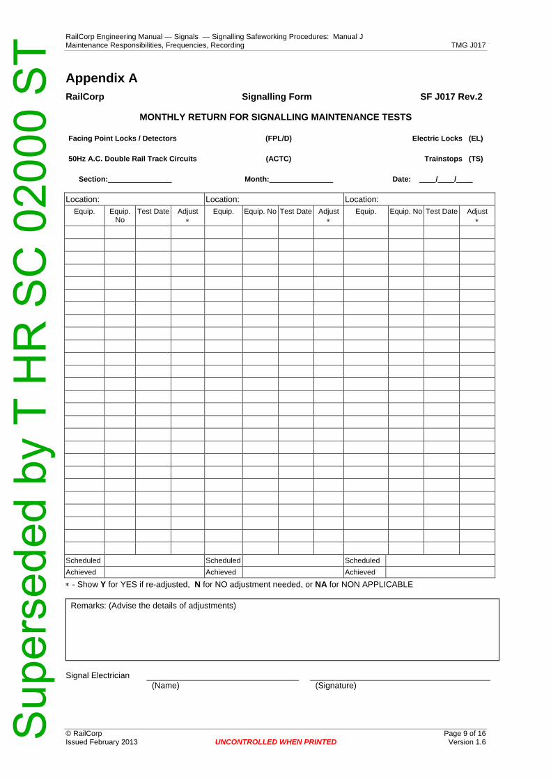
RailCorp Engineering Manual — Signals — Signalling Safeworking Procedures: Manual J Maintenance Responsibilities, Frequencies, Recording TMG J017
© RailCorp Page 9 of 16 Issued February 2013 UNCONTROLLED WHEN PRINTED Version 1.6
Appendix A RailCorp Signalling Form SF J017 Rev.2
MONTHLY RETURN FOR SIGNALLING MAINTENANCE TESTS
Facing Point Locks / Detectors (FPL/D) Electric Locks (EL)
50Hz A.C. Double Rail Track Circuits (ACTC) Trainstops (TS)
Section: Month: Date: / /
Location: Location: Location: Equip. Equip.
No Test Date Adjust
∗ Equip. Equip. No Test Date Adjust
∗ Equip. Equip. No Test Date Adjust
∗
Scheduled Scheduled Scheduled Achieved Achieved Achieved
∗ - Show Y for YES if re-adjusted, N for NO adjustment needed, or NA for NON APPLICABLE
Remarks: (Advise the details of adjustments)
Signal Electrician (Name) (Signature)
Sup
erse
ded
by T
HR
SC
020
00 S
T

RailCorp Engineering Manual — Signals — Signalling Safeworking Procedures: Manual J Maintenance Responsibilities, Frequencies, Recording TMG J017
© RailCorp Page 10 of 16 Issued February 2013 UNCONTROLLED WHEN PRINTED Version 1.6
POINTS TURNOUT CHECKLIST
To accompany Signal Engineering Waiver application for proposals to change Facing Point Lock and Detection Testing frequency
Date:- .................................
LOCATION................................................................................. POINTS No:- .....................
Turnout Type:- Conventional
1. General turnout condition including timbers or beams and ballast - do not include signalling equipment in this part of the assessment.
Condition Rating V Poor Poor Fair Good V Good 60 kg 1in 8¼ or 1 in 10½ on concrete beam ο ο ο ο ο or
60 kg 1 in 15 on concrete beams ο ο ο ο ο or
60 kg 1 in 8¼ or 1 in 10½ on timber sleepers ο ο ο ο v or
60 kg 1 in 15 on timber sleepers ο ο ο ο v or
53 kg 1 in 15 housed ο ο ο ο v or
53 kg 1 in 8¼ or 1 in 10½ std switch ο ο ο ο v or
53 kg 1 in 8¼ or 1 in 10½ thick switch ο ο ο ο v or
47 kg or lighter ο ο ο ο v
Ballast Condition (Fouled ⇒ Clean) ο ο ο ο ο
Ballast Height (Low/Excessive ⇒ Correct) ο ο ο ο ο
Is the turnout pumping ( High ⇒ negligible) ο ο ο ο ο
Has the ballast through the turnout been glued (bonded)
ο Yes ο No
Super-elevation through the turnout ο None ο <35mm ο >35mm
Switch tip condition ο ο ο ο ο
Type of chair ο Rail Brace ο Pressed Steel
Switch fit up to stockrail:
Normal ο ο ο ο ο
Reverse ο ο ο ο ο
Flangeway clearance (behind open switch) ο <50mm ο >50mm
General level and alignment ο ο ο ο ο
Sup
erse
ded
by T
HR
SC
020
00 S
T

RailCorp Engineering Manual — Signals — Signalling Safeworking Procedures: Manual J Maintenance Responsibilities, Frequencies, Recording TMG J017
Date:- .................................
LOCATION................................................................................. POINTS No:- …………....
Turnout Geometry ο ο ο
Drainage ο ο ο ο ο
Gauge ο <1432 ο 1432-1440
ο >1440
Turnout switch alignment ο within 25mm of square
ο more than 25mm out of square
Evidence of stockrail longitudinal movement
ο >20mm ο 10-20mm ο <10mm
Evidence of stockrail lateral movement ο <3mm ο >4mm
Heel condition (if not flexible switch) ο ο ο ο ο
© RailCorp Page 11 of 16 Issued February 2013 UNCONTROLLED WHEN PRINTED Version 1.6 Sup
erse
ded
by T
HR
SC
020
00 S
T

RailCorp Engineering Manual — Signals — Signalling Safeworking Procedures: Manual J Maintenance Responsibilities, Frequencies, Recording TMG J017
© RailCorp Page 12 of 16 Issued February 2013 UNCONTROLLED WHEN PRINTED Version 1.6
Date:- .................................
LOCATION................................................................................. POINTS No:- …………....
Turnout Type:- Conventional
2. Traffic:- Density, type and speed
Density: Trains per day ο <5 ο 5-20 ο 20-50
ο 50-100 ο 100-200 ο >200
Type ο EMU ο XPT or Mixed
ο Freight ο Heavy Haul
Speed
Straight Route ο < 60kph ο 60 - 90 ο 90 - 120
ο > 120 kph
Turnout Route ο < 20kph ο 20 - 40 ο >40kph
Percentage of trains through turnout route οο%
Line Class οο
3. Environment
Approach Conditions ο Continuously welded
ο Other turnouts
ο Rail joint within 3m of tip
Curvature approaching turnout ο none ο >400m ο <400m
Rising grade approaching turnout ο < 1 in 60 ο > 1 in 60
Level approaching turnout ο
Falling grade approaching turnout ο < 1 in 60 ο > 1 in 60
Locality Subject to flooding ο yes ο no
Corrosive (coal &mineral traffic) ο yes ο no
Seaboard ο yes ο no
Derailment Severity ## ο 5 ο 4 ο 3 ο 2 ο 1
## Derailment severity is defined by the location of the turnout relative to bridges over rivers or roads, embankments, other running lines, building or overbridge supports, frequented public areas.
Eg, a turnout immediately ahead of a bridge could rate “5”(very high) whereas a turnout on a single line in open flat country could rate “1” (very low)
.
Sup
erse
ded
by T
HR
SC
020
00 S
T

RailCorp Engineering Manual — Signals — Signalling Safeworking Procedures: Manual J Maintenance Responsibilities, Frequencies, Recording TMG J017
© RailCorp Page 13 of 16 Issued February 2013 UNCONTROLLED WHEN PRINTED Version 1.6
Date:- .................................
LOCATION................................................................................. POINTS No:- …………....
Turnout Type:- Conventional
4 Signalling Equipment:- Type and condition
Type ο Electric ο EP ο mech
ο Hydraulic
ο Clamp Lock ο Claw Lock
Back Driver(s) ο None ο One ο Two
V Poor Poor Fair Good V Good
Condition of external equipment ο ο ο ο ο
Condition of mechanism(s) ο ο ο ο ο
Installation Standard
Alignment of rodding ο ο ο
Electric Switch Machine Type
Mechanical Drive ο Interlock Machine ο Ground frame
60 kg 1in 8¼ or 1 in 10½, additional gauge rod fitted
ο Yes ο no
Type of extension piece ο ball joint ο rubber bush
For Mechanical operation only,
Adjustment remaining on 10x18 crank
ο < 65mm ο > 65mm
Escapement between bobbin and cradle
ο <10mm ο >10mm
Lock and/or Detection Adjustment History
ο <2 months ο 2 - 4 months Lock and/or detector required adjusted during testing or periodic maintenance at intervals of ο <4 - 6 months ο ο >6 months
Lock and/or detection failure history (include only “adjustment” failures)
No of failures past 3 months at intervals of ο
No of failures past 12 months ο
Signed: ........................................................................
District Signal Engineer
Sup
erse
ded
by T
HR
SC
020
00 S
T

RailCorp Engineering Manual — Signals — Signalling Safeworking Procedures: Manual J Maintenance Responsibilities, Frequencies, Recording TMG J017
POINTS TURNOUT CHECKLIST
To accompany Signal Engineering Waiver application for proposals to change Facing Point Lock and Detection Testing frequency
Date:- ..................................
LOCATION:-................................................................................. POINTS No:-......................
Turnout Type:- Tangential
1. General turnout condition including timbers or beams and ballast- do not include signalling equipment in this part of the assessment.
Condition Rating
V Poor Poor Fair Good V Good
190 - 250 m radius on concrete beams ο ο ο ο ο or
300 - 800 m radius on concrete beams ο ο ο ο ο or
1200 m radius on concrete beams ο ο ο ο ο or
190 - 250 m radius on timber sleepers ο ο ο ο v or
300 - 800 m radius on timber sleepers ο ο ο ο v or
1200 m radius on timber sleepers ο ο ο ο v
Ballast Condition (Fouled ⇒ Clean) ο ο ο ο ο
Ballast Height (Low/Excessive ⇒ Correct) ο ο ο ο ο
Is the turnout pumping ( High ⇒ negligible) ο ο ο ο ο
Has the ballast through the turnout been glued (bonded)
ο Yes ο No
Super-elevation through the turnout ο None ο <35mm ο >35mm
Switch tip condition ο ο ο ο ο
Switch fit up to stockrail:
Normal ο ο ο ο ο
Reverse ο ο ο ο ο
Flangeway clearance (behind open switch)
ο <50mm ο >50mm
General level and alignment ο ο ο ο ο
Turnout Geometry ο ο ο
Drainage ο ο ο ο ο
Gauge ο <1432 ο 1432-1440
ο >1440
Turnout switch alignment ο within 25mm of square
ο more than 25mm out of square
Evidence of stockrail longitudinal movement
ο >20mm ο 10-20mm ο <10mm
Evidence of stockrail lateral movement ο >4mm
© RailCorp Page 14 of 16 Issued February 2013 UNCONTROLLED WHEN PRINTED Version 1.6 Sup
erse
ded
by T
HR
SC
020
00 S
T

RailCorp Engineering Manual — Signals — Signalling Safeworking Procedures: Manual J Maintenance Responsibilities, Frequencies, Recording TMG J017
© RailCorp Page 15 of 16 Issued February 2013 UNCONTROLLED WHEN PRINTED Version 1.6
Date:- ..................................
LOCATION:-................................................................................. POINTS No:-......................
2. Traffic:- Density, type and speed
Density: Trains per day ο <5 ο 5-20 ο 20-50
ο 50-100 ο 100-200 ο >200
Type ο EMU ο XPT or Mixed
ο Freight ο Heavy Haul
Speed
Straight Route ο < 60kph ο 60 - 90 ο 90 - 120
ο > 120 kph
Turnout Route ο < 25kph ο 25-50 ο >60-80
ο > 80kph
Percentage of trains through turnout route οο%
Line Class οο
3. Environment
Approach Conditions ο Continuously welded
ο Other turnouts
ο Rail joint within 3m of tip
Curvature approaching turnout ο none ο >400m ο <400m
Rising grade approaching turnout ο < 1 in 60 ο > 1 in 60
Level approaching turnout ο
Falling grade approaching turnout ο < 1 in 60 ο > 1 in 60
Locality Subject to flooding ο yes ο no
Corrosive (coal & mineral traffic) ο yes ο no
Seaboard ο yes ο no
Derailment Severity ## ο 5 ο 4 ο 3 ο 2 ο 1
## Derailment severity is defined by the location of the turnout relative to bridges over rivers or roads, embankments, other running lines, building or overbridge supports, frequented public areas. Eg, a turnout immediately ahead of a bridge could rate “5” whereas a turnout on a single line in open flat country could rate “1”.
Sup
erse
ded
by T
HR
SC
020
00 S
T

RailCorp Engineering Manual — Signals — Signalling Safeworking Procedures: Manual J Maintenance Responsibilities, Frequencies, Recording TMG J017
© RailCorp Page 16 of 16 Issued February 2013 UNCONTROLLED WHEN PRINTED Version 1.6
Date:- .................................
LOCATION................................................................................. POINTS No:- …………....
Turnout Type:- Tangential
4 Signalling Equipment:- Type and condition
Type ο Electric ο EP
Back Driver(s) ο None ο One ο Two
ο One plus spring assist
V Poor Poor Fair Good V Good
Condition of external equipment ο ο ο ο ο
Condition of mechanism ο ο ο ο ο
Installation Standard
Alignment of rodding ο ο ο
OR
Electric Switch Machine Type ........................................................................
Back Driver(s) ο None ο One ο Two
ο One plus spring assist
V Poor Poor Fair Good V Good
Condition of external equipment ο ο ο ο ο
Condition of mechanism ο ο ο ο ο
Installation Standard
Alignment of rodding ο ο ο
Lock and/or Detection Adjustment History
ο <2 months ο 2 - 4 months Lock and/or detector required adjusted during testing or periodic maintenance at intervals of ο <4 - 6 months ο ο >6 months
Lock and/or detection failure history (include only “adjustment” failures)
No of failures past 3 months ο
No of failures past 12 months ο
Signed: ........................................................................
District Signal Engineer
Sup
erse
ded
by T
HR
SC
020
00 S
T

RailCorp Engineering Manual — Signals — Signalling Safeworking Procedures: Manual J Depot Overhaul of Vital Signalling Equipment TMG J018
© RailCorp Page 1 of 2 Issued May 2010 UNCONTROLLED WHEN PRINTED Version 1.1
TMG J018
DEPOT OVERHAUL OF VITAL SIGNALLING EQUIPMENT
Version 1.1
Issued May 2010
Document control
Version Date Summary of change 1.0 September 2005 Replaced SC 00 52 00 18 SI Depot Overhaul of Vital Signalling
Equipment. 1.1 May 2010 Application of TMA 400 format
Contents 1 Introduction .............................................................................................................................2
Sup
erse
ded
by T
HR
SC
020
00 S
T

RailCorp Engineering Manual — Signals — Signalling Safeworking Procedures: Manual J Depot Overhaul of Vital Signalling Equipment TMG J018
© RailCorp Page 2 of 2 Issued May 2010 UNCONTROLLED WHEN PRINTED Version 1.1
1 Introduction Vital signalling operating equipment which is defective or due for workshop inspection or overhaul shall be forwarded to an approved equipment repairer.
In some cases, workshop type inspections, repairs and/or overhauls for vital signalling operating equipment may be carried out in a district depot provided this is authorised by the Principal Engineer Signalling Technology after ensuring that the level of repair is documented and that the particular signalling employees involved are suitably trained and accredited and that the supporting facilities, tools, test equipment, methods and documentation are appropriate and available.
Complex or safety-critical depot repair or overhaul activity is to be covered by documented work instructions.
Depot repaired or overhauled equipment must be inspected and tested to specification requirements and fixed with a label detailing the testers name and title, the name of depot and the test date.
The Maintenance Signal Engineer is to keep a register of all authorised depot repair and overhaul arrangements. The register shall include for each particular type of equipment the respective signalling depot, signalling employees and the level of repair or overhaul authorised.
The Maintenance Signal Engineer shall consult with the Principal Engineer Signalling Technology or their respective staff for advice on requirements and in regard to any new arrangements.
Sup
erse
ded
by T
HR
SC
020
00 S
T

RailCorp Engineering Manual — Signals — Signalling Safeworking Procedures: Manual J Cleanliness and Lubrication of Mechanical Signalling Equipment TMG J019
© RailCorp Page 1 of 2 Issued May 2010 UNCONTROLLED WHEN PRINTED Version 1.1
TMG J019
CLEANLINESS AND LUBRICATION OF MECHANICAL SIGNALLING
EQUIPMENT
Version 1.1
Issued May 2010
Document control
Version Date Summary of change 1.0 September 2005 Replaced SC 00 52 00 19 SI Cleanliness and Lubrication of
Mechanical Signalling Equipment 1.1 May 2010 Application of TMA 400 format
Contents 1 Introduction .............................................................................................................................2
1.1 Cleaning.....................................................................................................................2 1.2 Interlocking Machines at Intermediate Sidings, including Drawer Locks ..................2
Sup
erse
ded
by T
HR
SC
020
00 S
T

RailCorp Engineering Manual — Signals — Signalling Safeworking Procedures: Manual J Cleanliness and Lubrication of Mechanical Signalling Equipment TMG J019
© RailCorp Page 2 of 2 Issued May 2010 UNCONTROLLED WHEN PRINTED Version 1.1
1 Introduction All mechanisms and connections shall be kept free from dirt and grit to reduce wear and help to reveal defects in their early stages.
1.1 Cleaning
Mechanical signalling equipment and connections, as applicable, shall be cleaned as explained below.
The cleaning should be done by means of knife or scraper and dry brush. After all dirt has been removed, the connections shall be lightly oiled. Any excess oil should be wiped off with a cloth or small brush.
Cotton waste shall not be used for applying or removing oil.
On sections where dusty conditions are experienced and in railway yards where various minerals are handled, the foregoing procedure shall be modified to suit circumstances, at the discretion of the Maintenance Signal Engineer. The surface of the connections should be painted with a suitable paint and oil applied only to the joints, pins etc.
All ballast, grit or dust or rubbish accumulating about connections shall be moved away, so that the connections work freely. Wet or damp conditions due to ineffective drainage, causing problems with equipment or connections, shall be reported to the civil staff.
Where required, points chairs are to be cleaned during routine maintenance or as rostered.
Steel wool must not be used in any area where there is electrical signalling apparatus or circuits.
1.2 Interlocking Machines at Intermediate Sidings, including Drawer Locks
These machines are to be oiled and cleaned by the Signalling Maintainer in the same way as the machines in signal boxes.
For this purpose, the lock faces of the Annett locks and the covers of the drawer locks may be removed but great care must be taken not to interfere with the locking mechanism.
Each time a cover has been removed and replaced the Annett Lock or Drawer Lock, as the case may be, must be carefully tested.
Sup
erse
ded
by T
HR
SC
020
00 S
T

RailCorp Engineering Manual — Signals — Signalling Safeworking Procedures: Manual J Security, Fire Protection, Weather PRoofing and Cleanliness of Signalling Equipment, Housings and Locations TMG J020
© RailCorp Page 1 of 4 Issued April 2012 UNCONTROLLED WHEN PRINTED Version 1.3
TMG J020
SECURITY, FIRE PROTECTION, WEATHER PROOFING AND
CLEANLINESS OF SIGNALLING EQUIPMENT, HOUSINGS AND
LOCATIONS
Version 1.3
Issued April 2012
Document control
Version Date Summary of change 1.0 Replaced SC 00 52 00 20 SI Security, Fire Protection, Weather
Proofing and Cleanliness of Signalling Equipment, Housings and Locations
1.1 July 2009 Removal of Section 1.5 Keys, (duplicated reference) and bring Section 1.1 into line with TMG J048
1.2 May 2010 Application of TMA 400 format 1.3 April 2012 Enhance the requirements in section 1.2 Prevention of Water Ingress
Contents 1 Introduction .............................................................................................................................2
1.1 Security ......................................................................................................................2 1.2 Prevention of Water Ingress ......................................................................................2 1.3 Tidiness .....................................................................................................................3 1.4 Fire Prevention ..........................................................................................................3 1.5 Access .......................................................................................................................3
Sup
erse
ded
by T
HR
SC
020
00 S
T

RailCorp Engineering Manual — Signals — Signalling Safeworking Procedures: Manual J Security, Fire Protection, Weather PRoofing and Cleanliness of Signalling Equipment, Housings and Locations TMG J020
© RailCorp Page 2 of 4 Issued April 2012 UNCONTROLLED WHEN PRINTED Version 1.3
1 Introduction Relay rooms, walk-in enclosures and lower floors of signal boxes and apparatus cupboards shall be kept clean and tidy. They shall be kept locked whenever possible. Surplus material shall not be stored in these places, unless it is neatly placed in racks or cupboards provided specially for that purpose. Highly inflammable material shall not be stored in these places.
Cleanliness and tidiness of signalling equipment and its surroundings facilitates access and visibility of the equipment for maintenance inspection and work as well as minimising the potential for failure caused by dirt and dust, corrosive conditions, loose objects obstructing or shorting out equipment, fire etc.
1.1 Security
Where electric locks are in use on interlocking machines, other than electric locks on Distant Signal levers, the doors, in the case of elevated boxes, or trap doors in platform level signal boxes, shall be secured by padlock or night latches.
All Signalling locations are to be secured by F04 Falcon Series locks and all field signalling equipment is to be secured by F08 Falcon Series locks, as per TMG J048 Appendix 1.
All signalling equipment operating mechanisms, relays, contacts, terminals etc, shall be housed in equipment units or in cupboards locked by Falcon Series locks as per TMG J048 Appendix 1, to prevent interference by unauthorised persons.
Locking arrangements are to be maintained in good condition and signalling apparatus and locations are to be left securely locked. Before closing up and locking equipment or locations, signalling personnel shall check that everything is in order and properly connected and that nothing has been left loose, foul of standard clearances, or in a potentially unsafe condition.
1.2 Prevention of Water Ingress
Signalling Maintainers are to keep insulating surfaces between electrical terminals clean and free from water to prevent leakage currents.
Signalling Maintainers are to ensure that signalling locations including relay rooms, cupboards, huts etc, are properly sealed to prevent the ingress of rainwater.
Conduit entries to trackside apparatus near ground level should be sealed with appropriate neutral cure silicon or similar sealants.
During routine maintenance Signalling Maintainers are to look for signs of water leakage and take appropriate corrective action.
During wet weather Signalling Maintainers are to avoid carrying out preventative maintenance which would allow water to enter equipment.
During wet weather Signalling Maintainers should examine the drainage around electrical apparatus to ensure water does not build up and enter the equipment, check locations housing vulnerable equipment for leaks, and remove any rubbish, cans etc, that have been blown or washed foul of operating equipment, drains, or into V or K crossings near insulated block joints etc.
After heavy rains Signalling Maintainers should check equipment, particularly in vulnerable locations and in areas additionally affected by extreme conditions, clean and
Sup
erse
ded
by T
HR
SC
020
00 S
T

RailCorp Engineering Manual — Signals — Signalling Safeworking Procedures: Manual J Security, Fire Protection, Weather PRoofing and Cleanliness of Signalling Equipment, Housings and Locations TMG J020
© RailCorp Page 3 of 4 Issued April 2012 UNCONTROLLED WHEN PRINTED Version 1.3
dry the equipment as necessary and utilise approved lubricating, penetrating and anti-corrosion sprays where advantageous. Where evidence of water ingress is apparent the equipment should be checked for correct operation.
Semi-sealed components shall be inspected to ensure that they are thoroughly dry and not internally contaminated. If there is evidence of foreign matter or moisture within the component, or it is not able to be easily checked, it shall be changed out.
Sealed components shall be checked to ensure the sealing remains effective.
Where wiring and contacts are not visible, but have been affected by water (such as Nippon point machine contactors and controllers), the apparatus is to be removed, cleaned and dried before replacement.
The Signalling Maintainers in charge of maintaining a section is responsible for reporting details of any water ingress which affects signalling equipment, to the Maintenance Signal Engineer.
1.3 Tidiness
Extensive damage may be caused to cables and equipment by fire; therefore inflammable materials such as paper, wood shavings, scrap timber, spent cleaning material and litter shall be cleared from and not be left near any cables, signal boxes, relay rooms, walk-in enclosures, equipment cupboards or cable pits and ducts.
1.4 Fire Prevention
It is essential that all Signalling Maintainers should take every precaution for the prevention of fires in or around signalling equipment and signal boxes and any situation considered to be a fire hazard shall be reported to the Maintenance Signal Engineer.
The underneath portions of elevated relay huts and equipment cupboards shall be enclosed to prevent the accumulation of rubbish.
Signalling Maintainers are responsible for ensuring that combustible material does not accumulate near in or around signalling apparatus, cables, cupboards or huts.
1.5 Access
Persons who are not required, as part of their normal duties, to examine or work on specific signalling equipment’s are not permitted entry to signalling locations housing such equipment, except under supervision.
Other than in emergencies, Signalling Maintainers who do not belong to the particular maintenance area are not to interfere with equipment on the particular maintenance area unless authorised by the Maintenance Signal Engineer responsible for the area concerned.
Sup
erse
ded
by T
HR
SC
020
00 S
T

RailCorp Engineering Manual — Signals — Signalling Safeworking Procedures: Manual J Security, Fire Protection, Weather PRoofing and Cleanliness of Signalling Equipment, Housings and Locations TMG J020
© RailCorp Page 4 of 4 Issued April 2012 UNCONTROLLED WHEN PRINTED Version 1.3
This page has been intentionally left blank
Sup
erse
ded
by T
HR
SC
020
00 S
T

RailCorp Engineering Manual — Signals — Signalling Safeworking Procedures: Manual J Minor Signalling Works Performed by Maintenance Groups TMG J021
© RailCorp Page 1 of 6 Issued May 2010 UNCONTROLLED WHEN PRINTED Version 2.2
TMG J021
MINOR SIGNALLING WORKS PERFORMED BY MAINTENANCE
GROUPS
Version 2.2
Issued May 2010
Document control
Version Date Summary of change 1.0 September 2005 First issue
2.0 August 2009 Standard name changed & updated in line with SPG 0711.9 implementation
2.1 December 2009 Remove SRA reference in Table 5 2.2 May 2010 Application of TMA 400 format
Contents 1 Introduction .............................................................................................................................2
1.1 Alterations and New Interfaces..................................................................................2 1.2 Responsibilities..........................................................................................................3 1.3 Weekly Notice............................................................................................................3 1.4 Certification................................................................................................................3 1.5 Project Handover .......................................................................................................4 1.6 Check List ..................................................................................................................4
Check List of Signalling Works ..................................................................................5
Sup
erse
ded
by T
HR
SC
020
00 S
T
RailCorp Engineering Manual — Signals — Signalling Safeworking Procedures: Manual J Minor Signalling Works Performed by Maintenance Groups TMG J021
© RailCorp Page 2 of 6 Issued May 2010 UNCONTROLLED WHEN PRINTED Version 2.2
1 Introduction Signalling work involving the installation, removal or alteration of signalling circuits and equipment, is generally distinguished from Maintenance Work and Like for Like Renewal Work by the requirement for certification by a Commissioning Engineer before the apparatus can be returned to service. General Renewals Work (as prescribed in TMG J011) also requires signalling apparatus to be certified by a Commissioning Engineer. The provisions of this standard particularly apply where minor signalling work is conducted by maintenance groups within their own region/district on behalf of the Maintenance Signal Engineer.
Before any signalling work is commenced, the Commissioning Engineer and the Maintenance Signal Engineer must collaborate to advise all affected parties, co-ordinate the works and obtain relevant approvals (eg: Engineering Change Request submitted to Configuration Control Board).
It is often necessary to ensure co-ordination and co-operation with Network Control and other affected parties when carrying out signalling works within operational areas.
The provisions of Standard Specification SPG 0711, shall apply, along with the applicable guidelines specified in the Project Management Methodology - Rail Asset Enhancement (RPMM RAE) module.
In addition, the precautions and procedures prescribed in TMG J010 Risks and Controls Associated with Testing and Certifying Equipment Worked on or Altered during Maintenance, TMG J011 Precautions Associated with Renewals Work and TMG J014 Document Control of Signal Plans and Circuit Books Issued to the Field shall be observed, as applicable.
1.1 Alterations and New Interfaces
The Maintenance Signal Engineer shall, as part of the Site Integrity Agreement for each signal job, nominate details of any other signal jobs at the location for which the submission of C.O.Cs is outstanding.
When there is more than one signalling job being performed in a location, the Maintenance Signal Engineer is to ensure that the accountability for all of the work in that location is clearly allocated to one Commissioning Engineer. The nominated Commissioning Engineer is to ensure that a clear separation exists between the signalling jobs and should a clear interface not exist (ie: one job is affecting the same circuit(s) as the other) then the process for changeover is to be confirmed with the Chief Engineer Signals and any staging arrangements necessary, is determined and implemented. A new design may be necessary if the sequence of work envisaged by the design is altered.
The Maintenance Signal Engineer and the Commissioning Engineer are to ensure any changes made are managed and that accountabilities remain clear for all the alterations.
Where an analysis of the new work identifies the presence of overlaps or interfaces, the Maintenance Signal Engineer shall ensure the work has reached completion, including the C.O.C returned to (and considered by) the design office before a new design is issued to the new Commissioning Engineer and before access is given to the next construction team. Alternatively, the Maintenance Signal Engineer shall initiate a joint investigation with the design office and the new Commissioning Engineer to determine any interfaces and risks. The agreed risk mitigation strategies shall be documented in the Site Integrity Agreement.
Sup
erse
ded
by T
HR
SC
020
00 S
T

RailCorp Engineering Manual — Signals — Signalling Safeworking Procedures: Manual J Minor Signalling Works Performed by Maintenance Groups TMG J021
© RailCorp Page 3 of 6 Issued May 2010 UNCONTROLLED WHEN PRINTED Version 2.2
1.2 Responsibilities
The Maintenance Signal Engineer is responsible for ensuring:
• The relevant approvals are obtained from the affected parties before any work is commenced.
• The installation, removal or alteration to signalling equipment is carried out by suitably licensed/authorised signalling personnel.
• The work is installed to approved signal design and equipment type approval. • Only one Commissioning Engineer is nominated where multiple works are being
performed within the same location. • All stakeholders are notified of the signalling changes. • The Network Rules and Procedures are followed. • The process for correcting the records is promptly initiated and followed through. • The availability of particular spares and the updating of the asset register as
applicable. • The RailCorp configuration policy is complied with. • The necessary documentation is complete and appropriately filed.
The Maintenance Signal Engineer may delegate these responsibilities to another Signal Engineer/Asset Engineer assigned to the region/district; however the Maintenance Signal Engineer is still ultimately accountable for the responsibilities listed.
The Commissioning Engineer is responsible for ensuring:
• The work is installed in accordance with the approved signal design & type approval and the installation complies with the relevant installation standards.
• The installation is tested in accordance with the Standard Specification SPG 0711, prior to the work being certified and restored for use.
• Ensure a clear interface for the work within a location. • Provide all necessary deliverables, in accordance with Standard Specification SPG
0711, to the Maintenance Signal Engineer.
1.3 Weekly Notice
All new signalling arrangements, removals, or alterations to the existing signalling arrangements must be advertised in the Weekly Notice prior to being brought into use in accordance with SPG 0703 Signalling Documentation and Drawings - Section 12.
1.4 Certification
A Commissioning Certificate (SPG 0711.7 Standard Forms) detailing the changes shall be completed for every alteration or addition to signalling arrangements which have been advertised in the weekly notice.
The certificate shall be completed and signed by the Commissioning Engineer.
A Certificate of Acceptance (SPG 0711.7 Standard Forms) shall also be compiled by the Commissioning Engineer and duly signed by both the Commissioning Engineer and the Maintenance Signal Engineer.
The relevant testing and certification records (SPG 0711.7 Standard Forms) shall be forwarded to the Maintenance Signal Engineer by the next business day after the work is complete.
Before signing the certificate the Commissioning Engineer shall be satisfied that the whole of the work has been inspected, tested and certified.
Sup
erse
ded
by T
HR
SC
020
00 S
T

RailCorp Engineering Manual — Signals — Signalling Safeworking Procedures: Manual J Minor Signalling Works Performed by Maintenance Groups TMG J021
© RailCorp Page 4 of 6 Issued May 2010 UNCONTROLLED WHEN PRINTED Version 2.2
If the Commissioning Engineer is unable to certify to the whole of the particular work referred to, the certificate shall be withheld, and a report forwarded to the Maintenance Signal Engineer. The certificate shall be forwarded as soon as all the work is complete.
The “booking-in certification” Section of the Infrastructure Booking Authority form (NRF 003) shall be signed jointly by the officers in charge on completion of the work. One copy shall be forwarded to the Maintenance Signal Engineer and one copy to Network Control.
A Mechanical/Relay/Route Control Locking Test Certificate (SF S4.304A/B) shall be completed whenever a new interlocking is brought into use, or whenever alterations are carried out to the locking in an existing interlocking machine. The certificate, signed off by the suitably accredited person who conducted the locking test, shall be forward to the Maintenance Signal Engineer, immediately the interlocking machine has been tested and brought into use.
The relevant documents shall be kept on a file relating to the particular project in the office of the Maintenance Signal Engineer.
Note:
All forms are to be kept on the Project File and/or Commissioning Work Package. Copies of the Interlocking Test Certificates are to be kept by the Maintenance Signal Engineer.
The Certified Office Copy shall be prepared signed and submitted in accordance with TMG J014, Document Control of Signal Plans and Circuit Books Issued to the Field.
1.5 Project Handover
A Project Handover shall be conducted in accordance with Section 10 of SPG 0711.2 Inspection and Testing of Signalling Plans, Programs, Documentation and Packages.
When the project has reached Practical Completion, the Commissioning Engineer shall advise the Maintenance Signal Engineer and arrange for a site inspection at the earliest convenience. Upon inspection, Practical Completion form W42F01 (RPMM RAE) shall be compiled and signed.
Any defects found shall be documented and an agreement reached on the rectification date.
Final completion of the project will be accepted once all defects have been rectified and once all configuration obligations including the following have been met:
a) All documentation including circuit books have been updated.
b) All asset information has been submitted and entered into applicable databases.
c) New equipment and spares have been catalogued and stock code numbers issued.
d) Any training obligations have been met.
Once these obligations have been met the Final Completion form W42F03 (RPMM RAE) can be signed off by the Commissioning Engineer and the Maintenance Signal Engineer.
1.6 Check List
The following check list covers typical items to be considered when carrying out minor signalling works.
Sup
erse
ded
by T
HR
SC
020
00 S
T
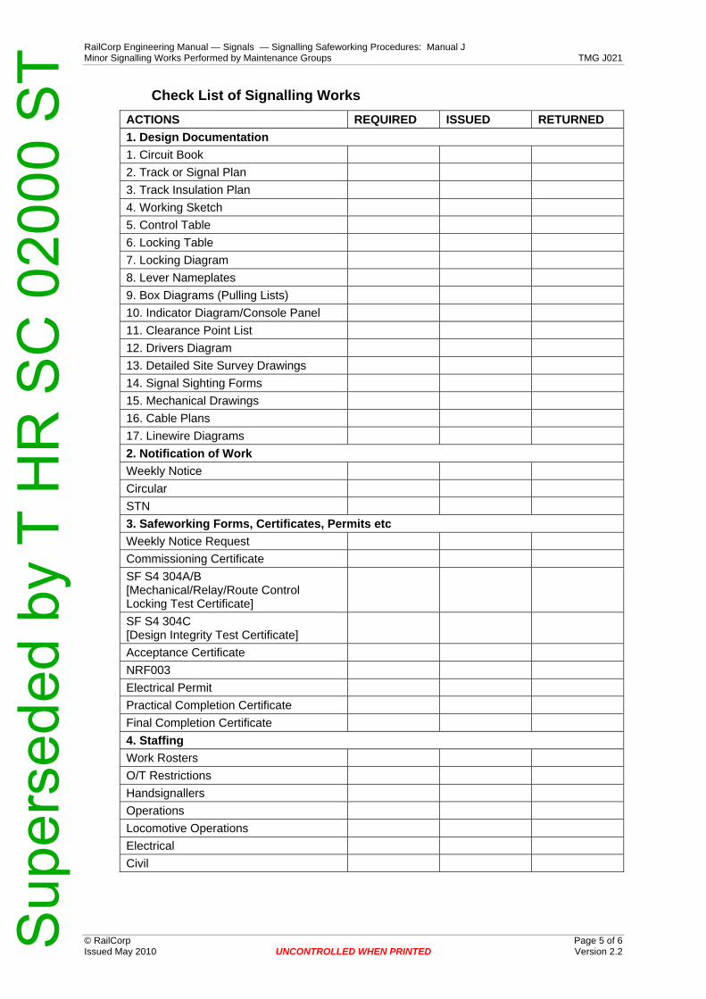
RailCorp Engineering Manual — Signals — Signalling Safeworking Procedures: Manual J Minor Signalling Works Performed by Maintenance Groups TMG J021
© RailCorp Page 5 of 6 Issued May 2010 UNCONTROLLED WHEN PRINTED Version 2.2
Check List of Signalling Works ACTIONS REQUIRED ISSUED RETURNED 1. Design Documentation 1. Circuit Book 2. Track or Signal Plan 3. Track Insulation Plan 4. Working Sketch 5. Control Table 6. Locking Table 7. Locking Diagram 8. Lever Nameplates 9. Box Diagrams (Pulling Lists) 10. Indicator Diagram/Console Panel 11. Clearance Point List 12. Drivers Diagram 13. Detailed Site Survey Drawings 14. Signal Sighting Forms 15. Mechanical Drawings 16. Cable Plans 17. Linewire Diagrams 2. Notification of Work Weekly Notice Circular STN 3. Safeworking Forms, Certificates, Permits etc Weekly Notice Request Commissioning Certificate SF S4 304A/B [Mechanical/Relay/Route Control Locking Test Certificate]
SF S4 304C [Design Integrity Test Certificate]
Acceptance Certificate NRF003 Electrical Permit Practical Completion Certificate Final Completion Certificate 4. Staffing Work Rosters O/T Restrictions Handsignallers Operations Locomotive Operations Electrical Civil
Sup
erse
ded
by T
HR
SC
020
00 S
T
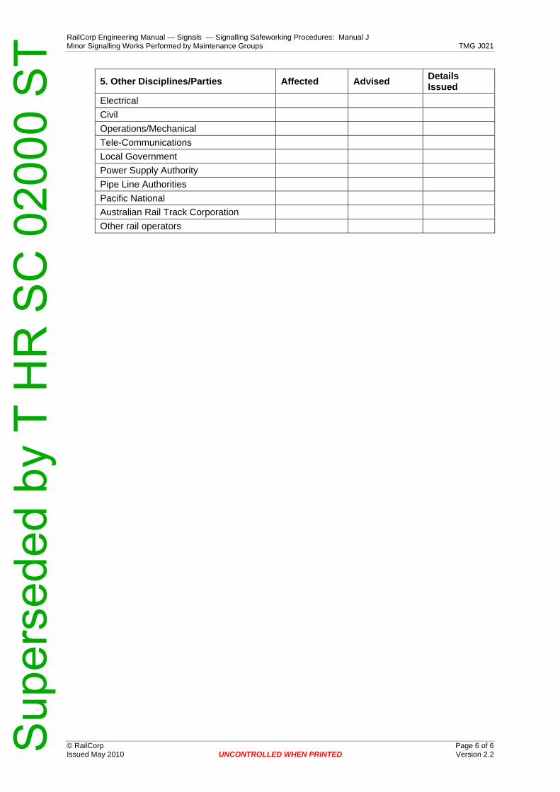
RailCorp Engineering Manual — Signals — Signalling Safeworking Procedures: Manual J Minor Signalling Works Performed by Maintenance Groups TMG J021
© RailCorp Page 6 of 6 Issued May 2010 UNCONTROLLED WHEN PRINTED Version 2.2
5. Other Disciplines/Parties Affected Advised Details Issued
Electrical Civil Operations/Mechanical Tele-Communications Local Government Power Supply Authority Pipe Line Authorities Pacific National Australian Rail Track Corporation Other rail operators
Sup
erse
ded
by T
HR
SC
020
00 S
T

RailCorp Engineering Manual — Signals — Signalling Safeworking Procedures: Manual J Testing of Interlockings – Maintenance Responsibilities TMG J022
© RailCorp Page 1 of 6 Issued May 2010 UNCONTROLLED WHEN PRINTED Version 1.3
TMG J022
TESTING OF INTERLOCKINGS – MAINTENANCE RESPONSIBILITIES
Version 1.3
Issued May 2010
Document control
Version Date Summary of change
1.0 September 2005 Replaced SC 00 52 00 22 SI Testing of Interlockings – Maintenance Responsibilities.
1.1 07 April 2008 Signal Engineer authorised to test Mechanical Interlocking (up to 8 levers)
1.2 3 March 2010 Requirements for testing mechanical frames greater than 8 levers following alteration to locking
1.3 May 2010 Application of TMA 400 format
Contents 1 Testing Interlockings..............................................................................................................2
1.1 Testing New Works and Alterations ..........................................................................2 1.2 Periodic Maintenance Interlocking Tests...................................................................2 1.3 Mechanical Locking ...................................................................................................2
1.3.1 Mechanical Locks.......................................................................................2 1.3.2 Mechanical Interlocking Frames ................................................................3
1.4 Relay and Route Control Interlockings ......................................................................3 1.5 Periodic Maintenance Interlocking Tests...................................................................4
2 Authority to Test Interlockings..............................................................................................4 2.1 Mechanical Locking and Mechanical Interlocking Frames – up to 8
levers .........................................................................................................................4 2.2 Mechanical Interlocking Frames – greater than 8 levers / Relay and
Route Control Interlockings .......................................................................................4 2.3 Design Integrity Tests ................................................................................................4 2.4 Function Tests to Control Tables and Circuit Design Principles ...............................4
Appendix A Forms........................................................................................................................5
Sup
erse
ded
by T
HR
SC
020
00 S
T
RailCorp Engineering Manual — Signals — Signalling Safeworking Procedures: Manual J Testing of Interlockings – Maintenance Responsibilities TMG J022
© RailCorp Page 2 of 6 Issued May 2010 UNCONTROLLED WHEN PRINTED Version 1.3
1 Testing Interlockings 1.1 Testing New Works and Alterations
Requirements for testing and certifying new works and alterations are detailed in Specification SPG 0711.1 to SPG 0711.6, “Inspection, Testing, Installation and Commissioning Requirements for Safety Assurance of New and Altered Works”.
When New Works or Alterations are commissioned into use, the Commissioning Engineer shall provide the Maintenance Signal Engineer with a copy of the associated locking table or control table, locking diagram and working sketch/signalling plan showing the locking details as commissioned. The Commissioning Engineer is to forward the Interlocking Test Certificates to the Maintenance Signal Engineer.
All changes are to be tested and certified by the Signal Engineer who carried out the tests and the tables and plans promptly brought up-to-date.
1.2 Periodic Maintenance Interlocking Tests Periodic maintenance interlocking tests shall be carried out by an authorised Signal Engineer (refer Section 2) for the primary reason of checking the interlocking and ensuring that it remains in accordance with the locking tables or interlocking portion of control tables, the locking diagrams and the working sketches/signalling plans.
The Maintenance Signal Engineer is responsible for adhering to interlocking test programs as set out in the Technical Maintenance Plan.
Performance indicators and/or status reports on the interlocking test programme shall be submitted by the Maintenance Signal Engineer at the agreed frequency.
Copies of the Interlocking Test Certificates are to be kept in the Maintenance Signal Engineer’s Office.
For mechanical and relay interlocking, Form S4.304 A/B, "Mechanical/Relay/Route Control Locking Test Certificate" should be used. This does not include track locking.
For new and altered works, Form S4.304C, "Design Integrity Test Certificate" is to be used, which would also encompass the certification electrical testing of relay interlockings, inclusive of track locking.
1.3 Mechanical Locking Mechanical locks and mechanical interlocking frames are subject to wear and tear.
1.3.1 Mechanical Locks
Locking tests on mechanical locking shall be completed and certified on a S4.304 A/B certificate by an authorised Signal Engineer (refer Section 2) every two (2) years.
The locking tests are performed to ensure that mechanical locking items (such as, Releasing Switch Locks, Annett Keys, Annett locks, Duplex Locks, Half Pilot Staff Locks, Emergency Locks, Bolt Locks, Bracket Locks, Staff Contact Locks, Staff Drawer Locks, Key Staffs, Loose Keys, Token Boards, Emergency Switch Machine Locks, Emergency Operation Locks, SL and XL locks on points) are effectively operational, safe and secure, and in accordance with Locking Tables, Control Tables, Locking Diagrams and Working Sketches/Signalling Plans.
Signalling notice boards are also to be checked as part of the interlocking certification.
Sup
erse
ded
by T
HR
SC
020
00 S
T

RailCorp Engineering Manual — Signals — Signalling Safeworking Procedures: Manual J Testing of Interlockings – Maintenance Responsibilities TMG J022
© RailCorp Page 3 of 6 Issued May 2010 UNCONTROLLED WHEN PRINTED Version 1.3
1.3.2 Mechanical Interlocking Frames
Mechanical interlocking machines as a matter of principle do not contain redundant interlocking.
Interlocking tests on mechanical interlocking frames shall be completed and certified on a S4.304A/B certificate by a suitably authorised Signal Engineer (refer Section 2) every two (2) years.
1.4 Relay and Route Control Interlockings Standard Relay and Route Control interlockings contain some redundancy for safety spread over the interlocking and control circuits.
Relay and Route Control interlocking integrity may be reduced by mechanical deterioration of electromechanical relays or by the deterioration of circuit and/or equipment insulation through aging, termite or rodent attack, overheating, fire, lightning damage etc or by electrical leakage paths tracking across insulating surfaces.
Defects, mechanical or electrical, which hold a relay falsely energised, are likely to be brought to early attention due to the back proving or cross proving of relays or due to equipment malfunction.
However, defects of a type which result in part of the selection in an interlocking circuit being bridged out may not necessarily come to attention.
Reliable earth leakage detection equipment and bus-bar voltage leak to earth tests together with down proving of relays assist in guaranteeing the integrity of a relay interlocking.
Relay and Route Control interlocking integrity may also be reduced by interference to the design configuration.
No person shall disconnect or connect wiring in working circuits unless they are qualified in signalling and do so in accordance with the rules and established procedures.
Relay and Route Control interlockings shall be electrically tested and certified on a S4.304A/B certificate every five years by a suitably authorised Signal Engineer (refer Section 2), in accordance with the locking tables or the interlocking portion of control tables except as follows.
Where the interlocking relays and interlocking circuits fully comprise
a) plug-in relays, and
b) P.V.C. insulated and sheathed cables, and
c) double switched external circuits to relays used for interlocking, and
d) reliable earth leakage detection fitted to vital supplies for interlocking circuits,
then they need not be subject to periodic interlocking tests except at the discretion of the Signal Engineer.
The mechanical locking associated with relay interlocking areas, (eg., Ground Frames, Releasing Switches, Annett Locks and Keys, E.S.M.L.'s etc), must be tested and certified every two years in accordance with applicable Locking Tables, Control Tables, Locking Diagrams and Working Sketches/Signalling Plans, as described for Mechanical Locking, and the S4.304A/B certificate shall be completed.
Sup
erse
ded
by T
HR
SC
020
00 S
T

RailCorp Engineering Manual — Signals — Signalling Safeworking Procedures: Manual J Testing of Interlockings – Maintenance Responsibilities TMG J022
© RailCorp Page 4 of 6 Issued May 2010 UNCONTROLLED WHEN PRINTED Version 1.3
1.5 Periodic Maintenance Interlocking Tests Form SF S4.304 A/B is the form to be used as “Mechanical/Relay/Route Control Locking Test Certificate”.
Form SF S4.304C is the form to be used as “Design Integrity Test Certificate”.
2 Authority to Test Interlockings 2.1 Mechanical Locking and Mechanical Interlocking Frames – up to 8
levers Signal Engineers (Field) are authorised, as part of their accreditation, to perform interlocking tests on Mechanical Locking and Mechanical Interlocking Frames of up to 8 levers.
2.2 Mechanical Interlocking Frames – greater than 8 levers / Relay and Route Control Interlockings Only Signal Engineers in possession of an Interlocking Certificate are authorised to perform interlocking tests on Mechanical Interlocking Frames greater than 8 levers, Relay and Route Control Interlockings.
Note:
Where the interlocking test is being performed to certify locking following an alteration to a Mechanical Interlocking Frame of greater than 8 levers, then two (2) Signal Engineers holding full interlocking accreditation (Interlocking Certificate) shall jointly conduct the test and subsequently both sign the test certificate to certify that the interlocking is correct.
A Design Integrity Test Engineer may substitute one of the two Signal Engineers holding full Interlocking Accreditation.
When conducting an interlocking test in this case, one tester shall observe the layout plan to ensure the relevant signalling principles are effective during the test eg: (levers pulled do not clear opposing signals, etc).
2.3 Design Integrity Tests The Design Integrity Test Engineer shall be accredited by the Chief Engineer Signals to conduct Design Integrity Tests.
2.4 Function Tests to Control Tables and Circuit Design Principles Signal Engineers (Field) are authorised, as part of their accreditation, to perform Function Tests to Control Tables and Circuit Design Principles as required.
Sup
erse
ded
by T
HR
SC
020
00 S
T
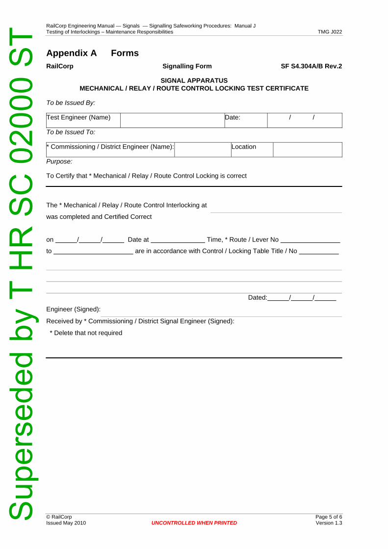
RailCorp Engineering Manual — Signals — Signalling Safeworking Procedures: Manual J Testing of Interlockings – Maintenance Responsibilities TMG J022
© RailCorp Page 5 of 6 Issued May 2010 UNCONTROLLED WHEN PRINTED Version 1.3
Appendix A Forms RailCorp Signalling Form SF S4.304A/B Rev.2
SIGNAL APPARATUS MECHANICAL / RELAY / ROUTE CONTROL LOCKING TEST CERTIFICATE
To be Issued By:
Test Engineer (Name) Date: / /
To be Issued To:
* Commissioning / District Engineer (Name): Location
Purpose:
To Certify that * Mechanical / Relay / Route Control Locking is correct
The * Mechanical / Relay / Route Control Interlocking at
was completed and Certified Correct
on / / Date at Time, * Route / Lever No
to are in accordance with Control / Locking Table Title / No
Dated: / /
Engineer (Signed):
Received by * Commissioning / District Signal Engineer (Signed):
* Delete that not required
Sup
erse
ded
by T
HR
SC
020
00 S
T

RailCorp Engineering Manual — Signals — Signalling Safeworking Procedures: Manual J Testing of Interlockings – Maintenance Responsibilities TMG J022
© RailCorp Page 6 of 6 Issued May 2010 UNCONTROLLED WHEN PRINTED Version 1.3
RailCorp Signalling Form SF S4.304C Rev.2
SIGNAL APPARATUS DESIGN INTEGRITY TEST CERTIFICATE
To be Issued By:
Test Engineer (Name) Date: / /
To be Issued To:
* Commissioning / District Engineer (Name): Location
Purpose:
To Certify that Design Integrity is correct
The Design Integrity Test at was completed and Certified Correct
on / / Date at Time, and is in accordance with
Control Table Title / No
Dated: / / and or
Design Integrity Test Plan/ Title No
Dated: / /
Test Engineer (Signed):
Received by * Commissioning / District Signal Engineer (Signed):
* Delete that not required
Sup
erse
ded
by T
HR
SC
020
00 S
T

RailCorp Engineering Manual — Signals — Signalling Safeworking Procedures: Manual J Insulation Inspection and Testing TMG J023
© RailCorp Page 1 of 14 Issued November 2010 UNCONTROLLED WHEN PRINTED Version 1.5
TMG J023
INSULATION INSPECTION AND TESTING
Version 1.5
Issued November 2010
Document control
Version Date Summary of change Replaced SC 00 52 00 23 SI - Insulation Inspection and Testing
1.1 27 June 2006 Test earth value changed & 70 volt bus test deleted 1.2 5 May 2009 Test Shunt value changed to 100K; Table added for IR
measurement temperature correction factors for common insulation material
1.3 May 2010 Application of TMA 400 format 1.4 July 2010 Temperature correction information amended to reference to SPG
0711 1.5 November 2010 Completed rewrite of Section 10 to Computer Based Interlocking
Systems (including exemptions to testing requirements)
Contents 1 Introduction .............................................................................................................................3
1.1 Purpose .....................................................................................................................3 1.2 Concept .....................................................................................................................3 1.3 New and Altered Work...............................................................................................3 1.4 Responsibilities..........................................................................................................3 1.5 Test Equipment..........................................................................................................4 1.6 Test Earths ................................................................................................................4 1.7 Inspection ..................................................................................................................5 1.8 Conditions For Testing...............................................................................................5 1.9 Test Frequencies .......................................................................................................5 1.10 Testing Complete Circuits..........................................................................................5
2 Relay Rooms, Signal Boxes, Level Crossing Huts, Walk-in Enclosures, equipment Location Cases and Cupboards.........................................................................6 2.1 Signalling Circuits : Internal .......................................................................................6
2.1.1 Power Supply Busbars...............................................................................6 2.1.2 Internal Wiring - Circuits with Earth Leakage Detectors. ...........................6 2.1.3 Internal Wiring - Circuits without Earth Leakage Detectors. ......................6 2.1.4 Wiring to Mechanical or Power Interlocking Frames..................................6
2.2 Method of Testing ......................................................................................................6
Sup
erse
ded
by T
HR
SC
020
00 S
T

RailCorp Engineering Manual — Signals — Signalling Safeworking Procedures: Manual J Insulation Inspection and Testing TMG J023
© RailCorp Page 2 of 14 Issued November 2010 UNCONTROLLED WHEN PRINTED Version 1.5
3 External Cables and wires .....................................................................................................7 4 External Power Supply Cables ..............................................................................................8 5 Non-Vital Wiring and Equipment ...........................................................................................9 6 Signal and Train Working Telephone Circuits .....................................................................9 7 Electric Staff Instruments.......................................................................................................9 8 Arrestors ..................................................................................................................................9 9 Track Circuit Cables ...............................................................................................................9 10 Computer Based Interlocking Systems (including exemptions to testing
requirements) ........................................................................................................................10 10.1 SSI Systems ............................................................................................................10 10.2 Microlok Systems.....................................................................................................10 10.3 Westrace Systems...................................................................................................10
11 Values of Insulation Resistance ..........................................................................................11
Sup
erse
ded
by T
HR
SC
020
00 S
T

RailCorp Engineering Manual — Signals — Signalling Safeworking Procedures: Manual J Insulation Inspection and Testing TMG J023
© RailCorp Page 3 of 14 Issued November 2010 UNCONTROLLED WHEN PRINTED Version 1.5
1 Introduction 1.1 Purpose
The purpose of maintenance insulation testing of circuits is to check for the process of degradation of the insulation of cables and wires and ultimately to determine the requirement for their renewal.
The purpose also is to detect and rectify insulation defects which could potentially result in irregularities due to current leakage cutting out one or more of the control elements of a circuit.
1.2 Concept
Insulation inspections and tests are to be performed to detect the presence of individual earths on conductors, degradation in the insulation of electrical circuits from earth and degradation in the insulation of electrical conductors from one another in multicore cables.
Leakage to earth significant enough to affect the safe and reliable operation of circuits, can occur through two individual earth faults or through the cumulative effects of a number of less significant earth faults - each less significant leakage path to earth adding up in parallel to give a significant total.
The ideal aim is to detect and rectify each single earth fault before a second earth fault develops.
Earth leakage detectors, voltage leak to earth tests, and insulation test instruments assist in detecting leakage to earth.
Visual inspections assist in detecting degradation of insulation.
Inspect and test for evidence of breakdown or degradation in the insulation of circuits from earth or from one another which may occur due to ageing, cracking, abrasion or other damage to the insulation, ingress of moisture into cables or across insulating surfaces, build up of dirt and grit etc. across insulating surfaces, distortion or movement of components affecting the clearance between metallic conductor parts, terminal lugs or wire strands coming into contact with frames, breakdown of surge arrestors, line wires coming into contact with trees, deposits caused by rotary contact wear, arcing, etc.
1.3 New and Altered Work
The cause of immediate or latent faults may be the result of poor installation practices, which can lead to undesirable electrical contact between wires, between cable cores, between wires and racks or equipment housings, and between wires and terminations.
Testing, either prior to commissioning or as a matter of routine, is no substitute for good installation practice and thorough supervision and management of the installation process.
New and altered work shall be supervised accordingly and shall be completely insulation tested and the results recorded before the installation is brought into use.
1.4 Responsibilities
Signalling Maintainers are responsible for earth leakage testing and insulation resistance testing of all electrical wiring and equipment in their sections.
Sup
erse
ded
by T
HR
SC
020
00 S
T
RailCorp Engineering Manual — Signals — Signalling Safeworking Procedures: Manual J Insulation Inspection and Testing TMG J023
© RailCorp Page 4 of 14 Issued November 2010 UNCONTROLLED WHEN PRINTED Version 1.5
They are responsible for routine inspection of visible wiring and equipment for signs of potential electrical leakage paths and for insulation damage or deterioration.
Signalling Maintainers shall record the insulation test results for circuits, cables and wires on Insulation Test Record sheets provided for the purpose.
On completion of the tests, the Signalling Maintainer shall forward results to the Maintenance Signal Engineer for checking.
Signalling Maintainers shall record busbar voltage leak to earth test results, and earth leakage detector tests, in a book or on cards, provided for the purpose and kept in the equipment location.
The Signalling Maintainer shall bring to the attention of the Maintenance Signal Engineer any abnormal earth leakage reading and the value of all insulation resistance which is less than the minimum required or is showing signs of deterioration, as well as any visual or other evidence indicating abnormal deterioration or damage of insulation.
The Principal Engineer Signal Operations & Assurance shall decide under which conditions the wiring or cabling shall remain in use.
Should the results of inspection or tests of insulation dictate that further special action/or testing is required, the Principal Engineer Signals Assurance shall direct accordingly.
The Maintenance Signal Engineer shall closely direct and control the insulation test programme, the defect repair programme and cable renewal programme.
The Maintenance Signal Engineer shall provide separate Insulation Test Records for each interlocking and associated block section.
Appropriate performance indicators shall be established to ensure that Maintenance Signal Engineer effectively and efficiently manage insulation testing, rectification of defects and cable renewals on the district.
Performance indicators and/or status reports on these programmes shall be submitted at the agreed frequency.
1.5 Test Equipment
The insulation test instrument used shall be an approved type. A 500 volt test instrument shall be used in all cases. In the case of impulse track circuit tail cables and 415V mains cables, the risk from earth faults is mitigated by other means, and the use of a 1000 volt test instrument is not required.
The 500 volt test instruments have a current rating of less than three (3) milliamps and may be used with safety on connected DC circuits.
Insulation test equipment shall be checked frequently to ensure that it works correctly. Faulty equipment shall be notified to the Maintenance Signal Engineer who will arrange for a replacement during repair and return.
1.6 Test Earths
The test earth used for insulation testing will normally be the main earth bus in the location, or a subsidiary earth bus bonded to the main earth bus.
A check shall be made to prove that a satisfactory test earth is obtained before testing commences, by measuring with the insulation tester between the earth bus and an alternate temporary test earth. The alternate earth may be the ELD Test Earth, GST Galvanised steel troughing or a temporary electrode.
Sup
erse
ded
by T
HR
SC
020
00 S
T

RailCorp Engineering Manual — Signals — Signalling Safeworking Procedures: Manual J Insulation Inspection and Testing TMG J023
© RailCorp Page 5 of 14 Issued November 2010 UNCONTROLLED WHEN PRINTED Version 1.5
Note: The rail of any track is not to be used as a test earth or alternate.
For insulation testing, any earth resistance that registers as a short circuit on the insulation tester (typically less than 10,000 ohms) will be a sufficient reference earth for insulation testing.
Where this earth resistance value cannot be obtained with standard earthing arrangements, the circumstances are to be referred to the Principal Engineer Signal Operations & Assurance for resolution.
1.7 Inspection
Before the testing of cables and wires is carried out, wires, cables and cable routes shall be visually examined for damage and deterioration of insulation as far as it is practical, particularly at points where there could be any possibility of disturbance which might cause chafing or mechanical damage to take place.
Replacement equipment shall be inspected to ensure it is in good order and condition before being placed in service.
At all times when maintaining equipment, Signalling Maintainers shall inspect as far as practical the condition of cable and wire insulation and the condition of insulating material and components comprising the equipment being maintained.
1.8 Conditions For Testing
Insulation tests should be carried out in wet/damp conditions whenever practicable. It is less effective to test external cables during dry or frosty conditions except where arid conditions always apply.
1.9 Test Frequencies
Any special tests stipulated by the Principal Engineer Signal Operations & Assurance shall be carried out as instructed and to the frequencies specified therein.
1.10 Testing Complete Circuits
Regular insulation testing of each external circuit, complete end to end, is not necessary as a general rule.
Should there be reason to believe that the integrity of circuits may be diminished because of undiscovered insulation defects then the Maintenance Signal Engineer shall include complete end-to-end circuit insulation testing as required.
The practice for regular insulation testing shall allow circuits to be divided into internal wiring in locations, main cables between locations, and local tail cables from trackside control equipment locations to trackside apparatus.
The requirements are prescribed as follows.
Sup
erse
ded
by T
HR
SC
020
00 S
T

RailCorp Engineering Manual — Signals — Signalling Safeworking Procedures: Manual J Insulation Inspection and Testing TMG J023
© RailCorp Page 6 of 14 Issued November 2010 UNCONTROLLED WHEN PRINTED Version 1.5
2 Relay Rooms, Signal Boxes, Level Crossing Huts, Walk-in Enclosures, equipment Location Cases and Cupboards
2.1 Signalling Circuits : Internal
2.1.1 Power Supply Busbars
Where earth leakage detectors are fitted they shall be tested and checked for reliable operation, by the operation of the test switch, on every maintenance visit.
Where power supply busbars are not fitted with reliable earth leakage detectors then, on each maintenance visit, the busbar voltage to earth for each leg shall be tested, with the fixed test equipment, where provided, or otherwise with a Fluke meter fitted with a 100K Ohm shunt (as use of 20K shunt might trip some ELDs set at low earth leakage sensitivity). Tests shall be daily at major interlockings where signalling staff are in attendance.
Under no circumstances is an ammeter to be connected between any busbar and earth.
2.1.2 Internal Wiring - Circuits with Earth Leakage Detectors.
All busbar voltage leak to earth test readings shall be recorded in an appropriate record book or on record cards provided for the purpose, and a check shall be made for any deviation from previous readings.
No maintenance insulation testing of internal wiring is required where reliable earth leakage detectors continuously monitor supply busbars that feed the internal wiring.
2.1.3 Internal Wiring - Circuits without Earth Leakage Detectors.
Where internal wiring is fed from power supply busbars without reliable earth leakage detection, then the internal wiring shall be insulation tested to earth and to frame every four (4) years for installations wired in standard PVC/nylon insulated wire, and every two (2) years for installations wired in other than PVC insulated wire.
2.1.4 Wiring to Mechanical or Power Interlocking Frames.
Circuit wiring to mechanical or power interlocking frames or to annett locks or safeworking instruments in signal boxes is to be treated as stipulated for tail cables in Section 3.
2.2 Method of Testing
For internal wiring and cabling of relay rooms, signal boxes, walk-in-enclosures, equipment location cases, cupboards, and level crossing huts, internal circuits (disconnected at outgoing cable links), shall be tested complete - with all relay contacts closed. Where this is not possible, the internal circuit shall be tested thoroughly by testing all the individual parts when the relay contacts can be closed.
These tests should be carried out only after the circuit to be tested has been disconnected from its power supply at both ends.
Electronic (solid state) based equipment such as rectifiers, diodes or transistors, electronic time limit or electronic flashing relays, solid state modules etc., shall be disconnected before testing to avoid damage from the insulation test meter voltage.
The insulation of each circuit should then be tested to earth using the same earth to which the metal of relay racks or location cupboards are connected (where these are earthed).
Sup
erse
ded
by T
HR
SC
020
00 S
T

RailCorp Engineering Manual — Signals — Signalling Safeworking Procedures: Manual J Insulation Inspection and Testing TMG J023
© RailCorp Page 7 of 14 Issued November 2010 UNCONTROLLED WHEN PRINTED Version 1.5
3 External Cables and wires The external main and local tail cables and wires which connect signal boxes, relay rooms, walk-in-enclosures and control equipment location cupboards and cases to one another and/or to vital signalling operating apparatus shall be tested as follows
a) Tests on vital signalling circuit wires and cables in an external route shall be applied to cover all of the following
i) all metallic screen sheaths or bare conductor drain wires in multicore cables - to earth, and to other conductors being tested in the cable.
and
ii) all spare conductors in each multicore cable - to screen/drain wire, to earth, and to one another.
and
iii) all spare single core conductors, - to earth and to one another.
and
iv) a minimum of two conductors (three if no screen/drain wire) in each multicore cable, - to earth, to screen/drain and to one another. (Spares count towards this minimum requirement e.g. if there are two (three if no screen/drain wire) or more spares in each multicore cable then the minimum requirement is satisfied by the testing of all spares, as in ii) above).
and
v) a minimum of three single core conductors, in each route connecting between equipment locations or operating apparatus, - to earth and to one another (Spares count towards this minimum requirement e.g. if there are three or more spares in the total number of single wires, then the minimum requirement is satisfied by the testing of all spares, as in iii) above).
and
vi) working conductors except where they are protected by reliable earth leakage detection or are connecting control elements which are double switched in the circuit - to earth, and, in multicore cables-to screen/drain and, in tail cables-to the metal casing/frame of the operating apparatus.
and
vii) in tail cables, except where the conductors are double switched in circuit, function test the external operating contact or apparatus to verify there are no core to core insulation defects. This is in preference to disconnecting wires from terminals for multicore cable core to core tests. Where links are provided at both ends, then core to core insulation tests may be carried out instead.
Tail cables are cables which are connected directly to trackside operating apparatus (e.g. release switches, annett locks, signals, points, track circuits, trainstops, level crossing lights and booms, and such like) or to mechanical interlocking machines (lever rotary contacts, catchrod
Sup
erse
ded
by T
HR
SC
020
00 S
T

RailCorp Engineering Manual — Signals — Signalling Safeworking Procedures: Manual J Insulation Inspection and Testing TMG J023
© RailCorp Page 8 of 14 Issued November 2010 UNCONTROLLED WHEN PRINTED Version 1.5
contacts, circuit controllers, electric locks, annett locks) or to safeworking instruments (electric staff instruments, block instruments).
If there are less spares then the minimum requirement in a multicore cable and working conductors are required to be disconnected, select from the outer layer of cores and record core numbers. Where some working conductors in the cable are connected directly through to busbars that are monitored by earth leakage detectors, and some are not, then those that are not shall be selected in preference. Where applicable the working conductors of single wire routes shall be similarly selected.
b) Where the cables and wires in the particular route are PVC insulated, PVC sheathed then insulation resistance testing shall be performed every four (4) years to the extent stipulated in a).
c) Where the cables and wires in the particular route are not PVC insulated, PVC sheathed (e.g. non PVC insulated line wires, VIR insulated wires, neoprene cables) then insulation testing shall be performed every two (2) years to the extent stipulated in a).
d) Cables with metallic screen sheaths or bare conductor drain wires earthed via lightning arrestors shall have the arrestors disconnected during tests.
e) The external cables and wires being tested shall be disconnected at the cable links from the internal equipment and wiring.
For external signalling cables and wires to operating apparatus, insulation testing of the metallic screen sheath or internal bare drain wire and of conductors to earth and to the metal structure of the individual trackside apparatus casing, should be done without disconnecting the operating apparatus but while the cables and wires are disconnected at the end remote from the apparatus which they service.(i.e. usually at the control equipment location cupboard, walk - in enclosure or relay room).
Note:
If the Metallic screen sheath of an external multicore cable has a low insulation resistance to earth then, except where reliable earth leakage detectors monitor the circuits, all single switched circuit conductors in the cable are to be insulation tested to screen and earth, and twenty percent of double switched circuit conductors are to be insulation tested to screen and earth.
4 External Power Supply Cables The metallic screen sheath of twin multicore signalling power cables shall be insulation tested to earth every four years for PVC insulated PVC sheathed cables and every two years for non PVC insulated cables.
Cables with metallic screen sheaths earthed via lightning arrestors shall have the arrestors disconnected during tests.
The conductors of signalling power cables and wires need not be tested where the supply busbars are connected to reliable earth leakage detectors or where residual current devices are fitted.
In other cases, signalling power cables and wires are to be insulation tested each conductor to earth every four years for PVC insulated PVC sheathed cables and every two years for non PVC insulated cables.
Sup
erse
ded
by T
HR
SC
020
00 S
T

RailCorp Engineering Manual — Signals — Signalling Safeworking Procedures: Manual J Insulation Inspection and Testing TMG J023
© RailCorp Page 9 of 14 Issued November 2010 UNCONTROLLED WHEN PRINTED Version 1.5
When the power cables and wires are being insulation tested they are to be disconnected from the supply and from the equipment, including disconnection from surge protection equipment.
Insulation testing of 120 volt AC power supply mains that only feed isolating transformers for SSI Trackside Functional Modules is not required.
5 Non-Vital Wiring and Equipment Non-vital wiring and/or equipment connected to non-vital busbars shall have the busbar voltage leak to earth tests carried out on each maintenance visit and the tests results shall be recorded.
Non-vital wiring and/or equipment connected into vital signalling circuits shall be insulation tested every two years unless protected by a reliable earth leakage detection system - to earth, to metal structures, and, if in a multicore cable, to screen/drain wire.
6 Signal and Train Working Telephone Circuits Signal and train working telephone circuit wires shall be insulation tested to earth every four (4) years, with multicore cables also tested metallic screen sheath to earth, and core to sheath.
7 Electric Staff Instruments The wiring of electric staff instruments shall be insulation tested during the examination of the instruments each two years by a Signal Engineer.
Signalling Maintainers are responsible for seeing that wiring insulation break down to frame does not occur in the equipment as a result of worn or damaged insulation or the replacement of screws.
8 Arrestors Arrestors or varistors to earth shall be tested using an ohm-meter or arrestor tester to ensure they are open circuit.
In lightning prone areas tests are to be carried out on each maintenance visit approaching, during, and immediately after, the lightning season.
Arrestor testers are provided for testing the breakdown voltage of arrestors or varistors; these breakdown voltage tests should be conducted every 52 weeks.
9 Track Circuit Cables Track circuit leads from the location to the bootleg riser, bond, or tuning unit, shall be disconnected at each end and each conductor insulation tested to earth and where applicable, metallic screen sheath to earth, every four years for PVC insulated PVC sheathed cable and every two years for non PVC insulated cable.
Measures must be taken to ensure the polarity is not reversed when reconnecting 50hz AC, DC and impulse track circuits.
Sup
erse
ded
by T
HR
SC
020
00 S
T

RailCorp Engineering Manual — Signals — Signalling Safeworking Procedures: Manual J Insulation Inspection and Testing TMG J023
© RailCorp Page 10 of 14 Issued November 2010 UNCONTROLLED WHEN PRINTED Version 1.5
10 Computer Based Interlocking Systems (including exemptions to testing requirements)
10.1 SSI Systems
Insulation testing is not required on the conductors of signal or point tail cables connected to TFM’s.
Insulation testing is also not required on:
• SSI Data Cables • Wiring associated with the MPM, DMPM, PPM and DLM equipment • Isolated power supplies between isolation transformers and modules
Refer to Solid State Interlocking (SSI) TMG J032 for additional Insulation testing requirements.
10.2 Microlok Systems
Insulation testing is not required on the conductors of tail cables that directly drive signal lamps from Microlok lamp driver cards.
Insulation testing is also not required on Microlok vital output relay circuits. Where isolation modules are in use, the circuit on the relay side is the equivalent of being double switched and isolated and insulation testing is not required.
50v input circuits shall be protected by an ELD, unless the input is independently driven by an isolated supply. In these cases, insulation testing is not required.
Insulation testing is not required on communication port and card addressing wiring.
On duplicated Microlok systems, insulation testing is required on that portion of the vital relay output between the duplication diodes and relay unless ELDs are fitted to all main 12v and 50v power supplies in the location.
Faults on direct drive signal lights and vital output drives will result in a shutdown of the cardfile.
Refer to Microlok Computer based Interlocking TMG J038 for additional Insulation testing requirements.
10.3 Westrace Systems
Westrace direct lamp drive circuits are not isolated but need not be insulation tested if a 120v AC ELD is fitted to the location.
Where isolation transformers are fitted to individual lamp drives, insulation testing is not required.
Westrace vital relay outputs are isolated outputs, however they are fitted with surge protection that may result in a lower resistance to earth. As the outputs are isolated, multiple specific faults are required to create an unsafe situation. As the likelihood is extremely low, insulation testing is not required.
Insulation testing on vital inputs is not required where ELD’s are fitted to these supplies (which may be in a different location) or the supply is isolated.
Insulation testing is not required on communications wiring.
Sup
erse
ded
by T
HR
SC
020
00 S
T
RailCorp Engineering Manual — Signals — Signalling Safeworking Procedures: Manual J Insulation Inspection and Testing TMG J023
© RailCorp Page 11 of 14 Issued November 2010 1.5 UNCONTROLLED WHEN PRINTED Version
Refer to Westrace Computer Based Interlocking TMG J039 for additional Insulation testing requirements.
11 Values of Insulation Resistance Values between infinity and 10 megohms insulation resistance to earth, irrespective of the type or length of cable, should be expected for signalling cables which are free of apparatus, ie, links disconnected.
Values between 10 and 1 megohm insulation resistance to earth may be expected for terminated cables and wires which are housed in location cupboards and walk-in enclosures.
Values better than 2 megohms insulation resistance to earth should be expected for local tail cables tested with the cable disconnected at the location but connected at the trackside apparatus.
Values below 1 megohm insulation resistance to earth for complete signalling or safeworking circuits and one half (1/2) megohm for telephone circuits are considered unsatisfactory.
If cable or wire insulation values are close to the minimum expected or the unsatisfactory values specified, and if they cannot be replaced promptly, the non-tested cores in the cable are also to be tested and the whole of that cable is to be retested at least annually until replaced.
When no obvious cause can be found and remedied for cables and wires that produce test results of a value less than the minimum expected values specified above, or less than the unsatisfactory values specified above, the details shall be reported immediately to the Maintenance Signal Engineer.
The Maintenance Signal Engineer shall analyse the insulation resistance results and inspect the cables and cable route to determine the risk involved and the urgency and extent of action required. Where all circuits are double switched the risk is less than with single switched circuits.
Immediate action pending renewal could include changing circuits on defective cores to non defective cores, temporary rewiring/recabling, insulation taping of defective sections, protective measures against disturbance, frequent insulation megger testing to monitor degradation, and monitoring busbar voltage to earth readings or installing earth leakage detectors.
Any vital signalling circuit with a conductor with an insulation resistance to earth value of 200,000 ohms or less shall be disconnected and booked out of use except where written authority is obtained from Principal Engineer Signal Operations & Assurance to retain the circuit in service under nominated conditions.
Note: Temperature Dependence of Insulation Resistance values
The insulation resistance of materials such as PVC is very temperature dependant, with the resistivity of PVC at 40°C being less that one tenth of the value at 20°C. While cables in buried routes are insulated against fluctuations in temperature, cables installed above ground, and especially in GST, may return apparently unacceptable insulation resistance values due to elevated temperatures alone. Where low IR values are measured and it is believed that elevated temperature may be the cause, the temperature of the cable should be estimated, and the equivalent 20°C IR value calculated as specified in SPG 0711.4 Clause 2.2.1.
Sup
erse
ded
by T
HR
SC
020
00 S
T

RailCorp Engineering Manual — Signals — Signalling Safeworking Procedures: Manual J Insulation Inspection and Testing TMG J023
Insulation Type ELD Fitted
Double Switched in Circuit
Apparatus Function Test/Core to Core
Insulation Test
Test Frequency (years)
Insulation Test Screen/ Drain Wire
Spare Conductors
Conductors Working or
Spare
PVC ELD D/S - - - NIL - PVC ELD NOT D/S - - - NIL - PVC NO ELD D/S - - - ALL 4 INTERNAL PVC NO ELD NOT D/S - - - ALL 4 CABLES/WIRES NON PVC ELD D/S - - - NIL - NON PVC ELD NOT D/S - - - NIL - NON PVC NO ELD D/S - - - ALL 2 NON PVC NO ELD NOT D/S - - - ALL 2
Table 1 - Test Frequencies
Note:
Wherever cables are visible they are to be regularly examined. If there are any indicators that cable insulation is deteriorating or defective then more extensive insulation testing than shown above is required.
© RailCorp Page 12 of 14 Issued November 2010 UNCONTROLLED WHEN PRINTED Version 1.5 S
uper
sede
d by
T H
R S
C 0
2000
ST

RailCorp Engineering Manual — Signals — Signalling Safeworking Procedures: Manual J Insulation Inspection and Testing TMG J023
Insulation Type ELD Fitted
Double Switched in
Circuit Apparatus Function Test/Core to Core
Insulation Test
Test Frequency (years)
Insulation Test *1)
Screen/ Drain Wire
Spare Conductors
*2)
Conductors Working or
Spare
PVC ELD D/S - ALL NIL 4 PVC ELD NOT D/S CC ALL MIN 2 4 PVC NO ELD D/S - ALL MIN 2 4 EXTERNAL PVC NO ELD NOT D/S CC ALL ALL 4 MAIN CABLES/WIRES NON PVC ELD D/S - - ALL MIN 3 2 NON PVC ELD NOT D/S CC - ALL MIN 3 2 NON PVC NO ELD D/S - - ALL MIN 3 2 NON PVC NO ELD NOT D/S CC - ALL ALL 2 PVC ELD/RCD - - - NIL 4 EXTERNAL PVC NO ELD - - - ALL 4 P OWER CABLES NON PVC ELD/RCD - - - - NIL - NON PVC NO ELD - - - - ALL 2
Table 2 - Test Frequencies
Note:
*1) CC Core to core insulation tests of the necessary working conductors in the multicore cable are to be used to verify no core to core insulation breakdown. The links in the locations at each end are to be opened.
*2) Include test of spare conductors to one another and, in multicore cables, to screen/drain wire. Where ever cables are visible they are to be regularly examined. If there are any indicators that cable insulation is deteriorating or defective then more extensive insulation testing than shown above is required.
© RailCorp Page 13 of 14 Issued November 2010 UNCONTROLLED WHEN PRINTED Version 1.5 S
uper
sede
d by
T H
R S
C 0
2000
ST

RailCorp Engineering Manual — Signals — Signalling Safeworking Procedures: Manual J Insulation Inspection and Testing TMG J023
Insulation Type ELD Fitted
Double Switched in circuit
Apparatus Function Test/Core to Core
Insulation Test
Test Frequency (years)
Insulation Test * 1)
Screen/Drain Wire
Spare Conductors
* 2)
Conductors Working or
Spare
PVC ELD D/S - ALL NIL 4 PVC ELD NOT D/S F/CC ALL MIN 2 4 PVC NO ELD D/S - ALL MIN 2 4 EXTERNAL PVC NO ELD NOT D/S F/CC ALL ALL 4 LOCAL (TAIL) CABLES/WIRES NON PVC ELD D/S - - ALL MIN 3 2 NON PVC ELD NOT D/S F/CC - ALL MIN 3 2 NON PVC NO ELD D/S - - ALL MIN 3 2 NON PVC NO ELD NOT D/S F/CC - ALL ALL 2
Table 3 - Test Frequencies
Note:
*1) F/CC Carry out function tests of external contacts of operating apparatus to verify no core to core insulation breakdown. Core to core insulation tests of all working conductors in the multicore cable may be used instead but not if more them one wire at a time has to be disconnected from its terminal in the apparatus. The links at the location end are to be opened.
*2) Include test of spare conductors to one another. Also test spare and working conductors to metal casing/frame of operating apparatus, and in multicore cables, to screen/drain.
Wherever cables are visible they are to be regularly examined. If there are any indicators that cable insulation is deteriorating or defective then more extensive insulation testing is required
© RailCorp Page 14 of 14 Issued November 2010 UNCONTROLLED WHEN PRINTED Version 1.5 S
uper
sede
d by
T H
R S
C 0
2000
ST

RailCorp Engineering Manual — Signals — Signalling Safeworking Procedures: Manual J Vital Signalling Relays TMG J024
© RailCorp Page 1 of 16 Issued October 2010 UNCONTROLLED WHEN PRINTED Version 2.2
TMG J024
VITAL SIGNALLING RELAYS
Version 2.2
Issued October 2010
Document control
Version Date Summary of change 1.0 September 2005 Replaced SC 00 52 00 24 SI Vital Signalling Relays. 1.1 22 December 2008 Provision of procedure for replacement of ACVL relays with Q
style plug in conversion units 2.0 August 2009 Standard updated in line with SPG 0711.9 2.1 May 2010 Application of TMA 400 format 2.2 October 2010 Clarified requirement to test AC vane plug-in relays in 1.2.1
Contents 1 Introduction .............................................................................................................................3
1.1 Sealing of Relays.......................................................................................................3 1.2 Cyclic Changing and Overhaul of Relays ..................................................................3
1.2.1 General Policy ............................................................................................3 1.2.2 Plug in Conversion Units for ACVL Line Relays ........................................4 1.2.3 Jeumont Schneider Track relays................................................................4
1.3 Type of wire connecting to shelf relays .....................................................................4 2 Placing Signalling Relays into Service .................................................................................5
2.1 General ......................................................................................................................5 2.2 Shelf type relay - Recording relay change information..............................................6
3 Miniature Plug-In Relays BRB Series: Care of/Handling ...................................................7 4 Large Size (Standard ‘B’ Type) Plug-In-Relays Distorted Contact Carrier........................7 5 Precautions to be Taken when Changing Magnetically Latched Relays ..........................7
5.1 Route NLR and RLR Relays......................................................................................7 5.2 Point NLR and RLR relays.........................................................................................8 5.3 Release Switch NLR or RLR Relays .........................................................................8
6 Routine Examinations and Tests ..........................................................................................9 6.1 Examination of AC Relays, Vane all types. ...............................................................9 6.2 Examination of DC Relays, Shelf-Mounted .............................................................10 6.3 Examination of Plug-in Relays.................................................................................10 6.4 Testing of Time Limit Relays ...................................................................................10 6.5 Examination of Suspect Relays, all types................................................................10
Sup
erse
ded
by T
HR
SC
020
00 S
T

RailCorp Engineering Manual — Signals — Signalling Safeworking Procedures: Manual J Vital Signalling Relays TMG J024
© RailCorp Page 2 of 16 Issued October 2010 UNCONTROLLED WHEN PRINTED Version 2.2
7 Despatch, Transport and Handling of Relays ....................................................................11 8 Re-Use of Q Type Relays......................................................................................................11
8.1 Visual Inspection......................................................................................................11 8.2 Operating Tests .......................................................................................................11 8.3 Contact Full Current Cleaning .................................................................................12 8.4 Relays with more than Ten Years Use ....................................................................12 8.5 Relays in Service .....................................................................................................12 8.6 Alterations requiring spare contacts to be brought into service...............................12
Appendix A Forms......................................................................................................................13
Sup
erse
ded
by T
HR
SC
020
00 S
T
RailCorp Engineering Manual — Signals — Signalling Safeworking Procedures: Manual J Vital Signalling Relays TMG J024
© RailCorp Page 3 of 16 Issued October 2010 UNCONTROLLED WHEN PRINTED Version 2.2
1 Introduction The Maintenance Signal Engineer shall ensure there is an up to date program for the changing and overhaul of relays as required by the policy.
As the proper working of all relays is essential, the following instructions shall be most carefully observed and where Signalling Maintainers are in doubt with regard to the condition of any relay they shall report it to the Maintenance Signal Engineer immediately.
1.1 Sealing of Relays
All vital relays supplied by manufacturers and workshops are sealed, and all relays installed in the field that are not presently sealed, shall be considered as sealed and not opened.
This seal shall not be broken in the field except in exceptional circumstances when directed by a suitably accredited Signal Engineer. In the event of a defect being observed in a relay the seal shall be left intact until the relay is examined by a suitably accredited Signal Engineer.
1.2 Cyclic Changing and Overhaul of Relays
1.2.1 General Policy
The policy for changing and overhauling all shelf mounted relays and AC vane type plug-in relays is based on two (2) main classifications of relays, "Proved" and "Unproved".
Unproved shelf mounted relays and AC vane type plug-in relays shall be changed after 15 years in service and overhauled in the workshops or scrapped.
Relays which are proved to release (down proved in circuit) are not required to be changed on a regular basis but on an "as needed" basis as determined by the normal inspections by the signal electricians.
Shelf mounted relays and AC vane type plug-in relays used for cut tracks are to be changed on a 10 year basis.
In the case of all other plug-in relays, (not AC vane type), a regular overhaul period is not laid down.
Samples of plug-in relays, other than AC vane type, from typical installations are to be inspected in detail after 20 years in service to assess the need for overhaul or replacement of the complete group, or to assess the period to the next sample inspection.
This inspection shall be carried out in the Signal Workshops, Rail Equipment Centre, and shall be arranged by the signal electrician in conjunction with the Signal Engineer who shall advise the Manager, Signal Workshops (Rail Equipment Centre). The sample relays are to be completely dismantled during the inspection.
The Workshop Manager shall obtain a report from the workshops and forward a copy to the Principal Engineer Signal Technology. After the inspection report is accepted by the Principal Engineer Signal Technology the sample relays which were dismantled for inspection may be discarded.
Shelf mounted Signal Branch type DC relays shall not be used. If in service they are to be immediately replaced, preferably with a DN 11 type shelf relay.
Sup
erse
ded
by T
HR
SC
020
00 S
T
RailCorp Engineering Manual — Signals — Signalling Safeworking Procedures: Manual J Vital Signalling Relays TMG J024
© RailCorp Page 4 of 16 Issued October 2010 UNCONTROLLED WHEN PRINTED Version 2.2
1.2.2 Plug in Conversion Units for ACVL Line Relays
Any ACVL relay determined for replacement shall be replaced with a Q style plug in conversion unit.
When arranging to replace an in-service ACVL relay with a Q style plug in conversion unit, it will be necessary to survey the circuit book contact analysis sheet to ensure that there are no circuits passing through the ACVL that has a current that exceeds the 3 Ampere rating of the Q relay contact e.g. trainstop motor circuits.
Prior to placing a Q style plug in conversion unit into service, the conversion unit as a whole (complete unit – not just the relay) is to be inspected and compared to the Test Certificate accompanying the relay, that it is the same relay and that the form is signed by the workshop tester and workshop supervisor.
Any straps between the local and the line coil terminals are to be removed and not reinstalled.
Installation and testing is to be in accordance with TMG J011 Precautions Associated with Renewals Work and SPG 0711.9 Like for Like Procedures.
Note: Maintenance Signal Engineer authorisation is required for renewal of shelf relays with plug-in conversion units.
Once an ACVL relay has been replaced with a Q style plug in conversion unit, a "Notice of Installation of Shelf Relay Conversion Unit" is to be completed and returned to the Manager Signal Documentation, for updating of the circuit book.
For maintenance purposes, Q style plug in conversion units are to be considered as plug in relays.
1.2.3 Jeumont Schneider Track relays.
This type of relay is to be kept under review until a fault or deterioration rate requires their replacement.
1.3 Type of wire connecting to shelf relays
When a shelf relay is fitted with a detachable top, flexible stranded wire (eg 9/0.30mm) may be terminated on the detachable top using appropriate insulated crimp lugs. Ensure that bakelite terminal covers are fitted and the lugs on different terminals do not cross one another.
When a shelf relay is not fitted with a detachable top, flexible stranded wire must not be terminated directly onto the relay.
Single strand, stiff wire (eg 1/1.70mm) without crimp lugs is to be used on these relays. Where this is required to run to a “Q” type relay or similar which will not accept this wire, an interfacing terminal block shall be used.
In cases where flexible, stranded wire has already been terminated directly onto shelf relays the following is required:
a) Ensure that crimp lugs do not touch one another or other terminals.
b) Whenever it is necessary to change the relay or to disconnect then reconnect the wiring for any reason:
i) Each wire must be labelled with its relay terminal number and
Sup
erse
ded
by T
HR
SC
020
00 S
T

RailCorp Engineering Manual — Signals — Signalling Safeworking Procedures: Manual J Vital Signalling Relays TMG J024
© RailCorp Page 5 of 16 Issued October 2010 UNCONTROLLED WHEN PRINTED Version 2.2
ii) Each crimp lug must be insulated as it is removed from the relay with either suitable sized plastic tubing which will fit tightly over the crimp lug or with another equally secure product.
2 Placing Signalling Relays into Service 2.1 General
When placing relays in service, particularly shelf relays, care should be taken to ensure that the level of signalling integrity is maintained throughout the work and that no alteration of the principle design occurs without approval. Reference to other standards shall be made including; TMG J011 for precautionary measures when renewals work is undertaken and SPG 0711.9 for the procedural requirements and applicable work instructions when replacing identical equipment.
The integrity of all vital signalling relays to be placed into service is paramount particularly as they may be installed in circuits where they are not proved to release when de-energised.
Signalling relays must be handled, transported and stored with care and not in any manner, condition or circumstance that would subject them to damage or deterioration.
The relays must be stored on racks in enclosed buildings in a clean, dry and non-corrosive environment. They must always be kept in the upright position in case of any undetected foreign matter which has fallen to the bottom of the case moves to a critical position.
Spare overhauled relays with workshop testing dates in excess of that specified below shall not be placed into service and shall be resubmitted to the Signal Maintenance Engineer for retesting.
Plug-in DC Relays Seven (7) Years Plug-in AC Relays Three (3) Years DC Shelf Relays Five (5) Years AC Shelf Relays Three (3) Years
New “Q” Type plug-in relays which have been stored in their original boxes or packaging for periods up to seven (7) years may be used without being overhauled provided that the relay passes the visual examination specified in Section 8.1 and the operating tests specified in Section 8.2.
Relays which do not pass the inspection and/or test should be forwarded to the Signal Maintenance Engineer as described in Sections 8.1 and 8.2.
Prior to placing any plug-in relay in service it shall be closely inspected to see that the contacts are aligned correctly and that it has not been damaged in transit. When plug-in relays are to be changed, before insertion into the plug-in base, the Signalling Maintainer shall ensure that the replacement relay is the same voltage, the same contact arrangement (by direct examination of the contacts) and that the code pins are present in the same indexing locations. The base shall be fitted with one set only of five index holes. The Signalling Maintainer shall check the contacts to ensure they are not high resistance. Where relay test panels are provided this facility is to be utilised. The Signalling Maintainer shall check the operation of the relay in circuit and ensure that the functions controlled by it operate correctly.
Immediately prior to any relay being placed in service it must be examined at a bench under full lighting conditions by the signal maintainer who is to install the relay. The Signalling Maintainer shall also arrange a test circuit to check the relay under operation.
Sup
erse
ded
by T
HR
SC
020
00 S
T

RailCorp Engineering Manual — Signals — Signalling Safeworking Procedures: Manual J Vital Signalling Relays TMG J024
© RailCorp Page 6 of 16 Issued October 2010 UNCONTROLLED WHEN PRINTED Version 2.2
The Signalling Maintainer is to examine the relay under normal electrical operation, observing the energise/de-energise cycle several times to ensure that the mechanical operation is normal, unrestricted but not pounding, and that the relay drops fully away.
Where there is any cause to suspect that the relay is not operating correctly it shall be immediately labelled accordingly and sent to the Maintenance Signal Engineer for more detailed testing together with written advice of the problem.
Once the relay has been installed it shall be observed to function fully in its operating circuit and shall not be certified until the Signalling Maintainer is satisfied that it is operating correctly.
The Principal Engineer Signal Assurance shall be promptly advised of all incidents of an unsafe condition whether in use or in storage of a vital signalling relay and shall nominate a signal engineer from the Signal Engineering section and, as required, a person from the Signal Workshops at the Rail Equipment Centre, to examine the relay before it is unsealed.
Before placing a shelf-mounted relay in service special care shall be taken to remove the armature securing screw provided to prevent damage during transport. The arrangement of terminals vary for different manufacturers of shelf-mounted relays, it is therefore necessary that Signalling Maintainers take special care when replacing a relay by one of a different manufacture to see that the connections are placed on the correct relative terminals and that circuit diagrams are updated for any change in contact numbers. The relay shall be examined and bench tested by the Signalling Maintainer prior to installation.
Also before placing the shelf-mounted relay in service the suitably accredited Signalling Maintainer shall remove the nuts on the studs and check that the bottom nut is tightened down. This is to ensure that the pigtail is securely maintained by a tight armature stud or that the carbon pillar is securely maintained in position by a tight point stud. Excessive force shall not be applied on the bottom nut as this could cause the stud to fracture.
When a shelf-mounted relay has been replaced the Signalling Maintainer changing the relay is responsible for seeing that a thorough test and check is made of all circuits passing through the relay to ensure that no incorrect connections have been made and that the circuits are in accordance with the circuit diagrams.
In addition when any DC shelf-mounted relay or DC plug-in track relay or DC standard 'B' size plug-in relay is changed the "pick-up", "drop-away" and "working" currents of the new relay shall be tested.
SF J024/B "Relay Changed Forms", at present, shall be made out in duplicate by the Signalling Maintainer for all shelf relays replaced and these forms shall be forwarded to the Maintenance Signal Engineer immediately after the relay or relays have been changed. The Signalling Maintainer shall show all relevant particulars on these forms and certify that the circuits through the shelf-mounted relays have been tested and are correct.
2.2 Shelf type relay - Recording relay change information
In the event of a shelf type relay being tested, installed or removed from service the Signalling Maintainer shall fill out the relay changed form SF J024/B Rev.1 form and forward it to the Maintenance Signal Engineer for recording.
When a relay has been replaced, newly installed or removed permanently from service the local relay records or database is to be bought up to date to reflect the change. Details of newly installed or replaced relays including the install date are to be included.
Sup
erse
ded
by T
HR
SC
020
00 S
T

RailCorp Engineering Manual — Signals — Signalling Safeworking Procedures: Manual J Vital Signalling Relays TMG J024
© RailCorp Page 7 of 16 Issued October 2010 UNCONTROLLED WHEN PRINTED Version 2.2
3 Miniature Plug-In Relays BRB Series: Care of/Handling Cases have occurred where newly installed miniature plug-in signalling relays have failed to operate, and it was found that their contacts were out of adjustment due to distortion of their stationary contact support brackets.
It has been demonstrated that this fault was a result of the relay having been dropped or struck during transport or installation.
Extreme care shall be exercised in transporting and handling relays. Any relay which is bumped or dropped should be closely examined and tested, and if need be sent to the workshops for overhaul.
Because of the risk that relays may have been dropped or damaged without knowledge, any relay which is to be placed in service shall be visually inspected, then inserted in a relay test unit and observed to operate correctly before being plugged into service.
If there is any sign of damage to the case or to the relay or if the operation or the relay is in any way suspect if shall not be put into service but sent for overhaul.
4 Large Size (Standard ‘B’ Type) Plug-In-Relays Distorted Contact Carrier Special note should be taken, by all Signalling Maintainers concerned with the handling and placing into service of large size plug in relays that contacts can become seriously out of adjustment due to rough handling.
Before placing a relay into service it must be carefully examined to see that all contacts, both front and back, make with sufficient over travel and open sufficiently (when applicable). If a relay is suspect or in any way damaged it shall be sent to the Maintenance Signal Engineer for inspection.
Large size plug-in relays are particularly prone to maladjustment of contacts due to the alloy casting which carries the coil becoming misaligned at some angle other than 90 degrees relative to the relay base. This is usually caused by the relay being dropped during transit or installation.
When these relays are transported by any means they must be packed with the contact springs vertical and "THIS SIDE UP" labels applied appropriately.
5 Precautions to be Taken when Changing Magnetically Latched Relays Magnetically latched relays remain in the position to which they were last operated and for this reason special precautions are required to ensure that a relay is "down" before it is plugged into service. Magnetically latched relays are used for the parent relay of the route, point and release lock relays and the procedure for changing these relays is as follows.
5.1 Route NLR and RLR Relays
Prior to unplugging a route NLR or RLR relay the Signalling Maintainer shall:
a) Ensure that the signal to which the route lock relay applies is at stop, the route normalised, and that any train which is approaching the signal has been brought to a stand.
Sup
erse
ded
by T
HR
SC
020
00 S
T

RailCorp Engineering Manual — Signals — Signalling Safeworking Procedures: Manual J Vital Signalling Relays TMG J024
© RailCorp Page 8 of 16 Issued October 2010 UNCONTROLLED WHEN PRINTED Version 2.2
b) The magnetically latched relay which is to be placed in service shall then be plugged into the magnetically latched relay test base and the indicator lamp observed to ensure that the relay is down.
The relay to be withdrawn from service is then unplugged and the new relay removed from the test base and plugged into service.
Note:
After changing a route NLR relay both the route NLR and RLR may be down. This will be indicated by a steady white light in the button knob controlling the route and the button shall be pulled to energise the NLR.
5.2 Point NLR and RLR relays Prior to unplugging a point NLR or RLR relay the Signalling Maintainer shall:
a) Ensure that no trains are standing foul of or passing over or approaching the points concerned.
b) Ensure that all signals which protect the points concerned are at stop and that any trains which may be approaching those signals have been brought to a stand.
c) The magnetically latched relay which is to be placed in service shall then be plugged into the magnetically latched relay test base and the indicator lamp observed to ensure that the relay is down.
d) The relay to be withdrawn from the service is then unplugged and the new relay is removed from the test base and plugged into service.
Note:
After changing a point lock relay both point NLR and RLR relays may be down. This will be indicated by both point position lights extinguished, and the transit light flashing. Under these conditions it will be necessary to move the point lever to the centre position and then to return the lever to its previous position and thereby energises the point lock relay for the position in which the points are laying.
5.3 Release Switch NLR or RLR Relays
Prior to unplugging a release NLR or RLR relay the Signalling Maintainer shall:
a) Ensure that no trains are standing foul of or passing over or approaching the ground frame points concerned.
b) Ensure that all signals which protect the ground frame points are at stop and that any trains which may be approaching those signals have been brought to a stand.
c) The magnetically latched relay which is to be replaced into service must then be plugged into the magnetically latched relay test base and the indicator lamp observed to ensure that the relay is down.
d) The relay to be withdrawn from service is then unplugged and the new relay is removed from the test base and plugged into service.
Sup
erse
ded
by T
HR
SC
020
00 S
T

RailCorp Engineering Manual — Signals — Signalling Safeworking Procedures: Manual J Vital Signalling Relays TMG J024
© RailCorp Page 9 of 16 Issued October 2010 UNCONTROLLED WHEN PRINTED Version 2.2
6 Routine Examinations and Tests 6.1 Examination of AC Relays, Vane all types.
Vane and polyphase AC relays, including contacts, pigtails and terminals, shall be inspected periodically for any signs of abnormal conditions.
Examine all non-proved vane AC relays every 52 weeks and whenever the opportunity presents.
Particular attention shall be paid to the working of the vane and for any indication of the following conditions, by observation through the glass case.
The relay shall be observed to operate correctly.
Check for abnormal release operation of a relay, eg sluggish, jerky or not falling fully to the stop position may be due to defective bearings, warped bakelite tops, wax or other foreign matter in the bearings, vane obstructions, etc.
Check that there is no foreign matter or flaking plating or paint inside the relay.
Check for deposits of wax, varnish or paint on the vane which may indicate overheating of coils or contact with pole faces.
Check for scratches or abrasions on the vane which may indicate that the vane is distorted or that air gap tolerances are incorrect.
Check if the bottom of the vane could be spread due to striking the bottom of the relay case. This condition can first be detected by a mark in the paint of the case bottom. A vane allowed to spread could become jammed between the pole faces.
Check that the vane is central between and clear of pole faces. Vane distortion may be evident from observing the relay in operation.
Check the surface of the vane spindle for any accumulation of dust or discolouration which may be attributed to wear of the bearings.
Do not place in service AC vane shelf relays fitted with black coils without coil formers, as some these are suspected of releasing wax from the coils when hot.
If other types of relays in service exhibit evidence of wax deposits then details are to be reported.
Examine all non-proved AC vane shelf relays with black coils without coil formers for the presence of wax coatings and, where noted, check the release operation of the relay. Also examine the contacts for any noticeable presence of wax contamination.
Immediately change out non-proved AC vane shelf relays with black coils without coil formers and with evidence of wax and program those without evidence of wax for priority changout, and have the Maintenance Signal Engineer scrap this type of relay after removal from service.
Keep on record in the section depot a separate list of each and every non-proved relay circuit function on the section which is fitted with an AC vane shelf relay. This list would include track relays, track indicating relays, signal N1 relays, release switch normal relays, detector relays etc.
If correct operation of a relay is in doubt, advise the Maintenance Signal Engineer and change out the relay immediately and label it accordingly. The Maintenance Signal Engineer is to promptly examine the relay as follows:
Sup
erse
ded
by T
HR
SC
020
00 S
T

RailCorp Engineering Manual — Signals — Signalling Safeworking Procedures: Manual J Vital Signalling Relays TMG J024
© RailCorp Page 10 of 16 Issued October 2010 UNCONTROLLED WHEN PRINTED Version 2.2
a) Check that ends of split pins are properly spread.
b) Check that the counter weight lock nut is locking the counter weight and that they have not moved.
c) Examine roller stops for evidence of grooving.
d) Examine spring type stops for evidence of grooving and ensure that the spring is effective and is not fouled by its bracket when the relay is energised and that they are tight and there is no sign of cracking.
6.2 Examination of DC Relays, Shelf-Mounted
Signalling Maintainers are responsible for the inspection of all DC shelf-mounted relays on their section. These relays shall be inspected every 52 weeks and whenever the opportunity presents for any unusual condition and to see that the armature is operating freely and drops away promptly when the relay is de-energised. If any sluggishness or failure of the armature to drop away promptly is observed, the relay shall be replaced immediately and the Maintenance Signal Engineer advised. When making this check due allowance should be made for a slow release relay.
6.3 Examination of Plug-in Relays
Signalling Maintainers shall examine, to the extent practical without removal, all plug-in relays, both Standard ‘B’ size and miniature, on their sections every 52 weeks and whenever the opportunity presents. They shall particularly be on the look out for:
a) Any signs of the clear plastic in the covers fouling the contact assembly due to warping or cracking.
b) Any signs of contact burning, or pitting of the carbon contacts, and any signs of displaced carriers.
c) Any signs of rust on plated components or signs of excessive deterioration of the plating.
Signalling Maintainers shall replace relays if any of these or other defects are detected and advise the Maintenance Signal Engineer.
6.4 Testing of Time Limit Relays
Electro-mechanical type and thermal type time limit relays shall be regularly tested at not more than two years intervals to see that they operate at the specified timing and the necessary details entered on a SF J024/C form and forwarded to the Maintenance Signal Engineer.
The relay shall be considered defective if the timing varies by more than ten percent of the specified timing.
Defective relays shall be sent to the Maintenance Signal Engineer for attention.
RailCorp type approved electronic time limit relays, such as QTD5 time limit relays are not required to be tested.
6.5 Examination of Suspect Relays, all types
The Maintenance Signal Engineer is to promptly arrange for a relay replaced because of doubtful operation to be examined by a Signal Engineer delegated by the Principal
Sup
erse
ded
by T
HR
SC
020
00 S
T

RailCorp Engineering Manual — Signals — Signalling Safeworking Procedures: Manual J Vital Signalling Relays TMG J024
© RailCorp Page 11 of 16 Issued October 2010 UNCONTROLLED WHEN PRINTED Version 2.2
Engineer Signalling Technology, and the Manager, Signal Workshops, Rail Equipment Centre.
7 Despatch, Transport and Handling of Relays Relays removed or replaced shall be forwarded to the Signal Workshops (Rail Equipment Centre) for overhaul or scrapping with a label detailing the reasons for its removal.
Relays should be handled and transported at all times with care and always be kept in the upright position in case any foreign matter has escaped detection and can move into a critical position to prevent proper operation.
8 Re-Use of Q Type Relays Before Q Type (BRB930) miniature plug in relays, which have been in service for ten years or less, are considered for reuse in new or altered works, the following procedure of inspection and operating tests shall be carried out and the relay shall meet all performance criteria.
8.1 Visual Inspection
Visually examine the relay to ensure that:
a) Seals are intact.
b) The cover and base (base of the relay itself) mouldings are not chipped, cracked or warped.
c) Register pins are straight and correctly coded.
d) Plug-in contact fingers are not bent, distorted or burnt and have not lost tension.
e) There is no sign of overheating within the relay.
f) There are no signs of the plastic cover fouling the contact assembly or the assembly being misaligned.
g) Plated components are not corroded and are not showing signs of deterioration.
h) There is no loose or foreign matter inside the cover.
i) The cover is still transparent and there is no internal coating of a rust coloured, metallic or greasy nature.
If the relay has any of the defects listed above or if the seals are broken, the relay is to be returned to the workshops for scrapping or overhaul.
Relays which in all respects pass the visual test shall be operationally tested as follows.
8.2 Operating Tests Place the relay into the miniature relay test set and check.
a) Pick up and drop away values (see Relays Manual)
b) Normal operation i.e. no chatter, excessive hum, slow to pick up or drop away (except where this is a function of the particular relay).
c) Pick up and drop away times (where applicable).
Sup
erse
ded
by T
HR
SC
020
00 S
T

RailCorp Engineering Manual — Signals — Signalling Safeworking Procedures: Manual J Vital Signalling Relays TMG J024
© RailCorp Page 12 of 16 Issued October 2010 2.2 UNCONTROLLED WHEN PRINTED Version
Note:
If the relay fails a) or b) it shall be scrapped. If the relay fails c) it shall be returned to the workshops for scrapping or overhaul.
d) Check the contact resistance of each contact pair in the relay.
If the resistance is greater than 2 ohms the contact maybe able to be cleaned by cycle testing the contact at its full rated current. Retest for resistance. If now less than 2 ohms the relay may be re-used. If still more than 2 ohms the relay must be sent to the workshops for mechanical cleaning and service.
Note:
A relay with contact resistance readings up to 7.5 ohms may be re-used as a temporary measure if no replacement is available. This relay must be replaced without delay. Such relays shall be marked "High resistance contacts, relay to be replaced”.
8.3 Contact Full Current Cleaning
All relays which have had contacts full current cleaned MUST have a permanent label affixed which states “Nos .........contacts full current cleaned on .................. Signed ....................”.
8.4 Relays with more than Ten Years Use
Any Q type relay removed from service which has been in operational use for more than ten years shall, provided it passes visual inspection, be returned to the workshops for overhaul.
8.5 Relays in Service
The above procedure for carrying out visual inspections and operating tests may also be used to test and clean relay contacts which are in service or which have been removed from service with suspected or proven high resistance contacts.
8.6 Alterations requiring spare contacts to be brought into service.
Whenever there are circuit alterations and circuits are connected to spare contacts that have not been in use for some time there is a probability that the contact may be high resistance. Again cycle testing the spare relay contact with its full rated current before it is connected in service may reduce the contact resistance and should be carried out, as required.
Sup
erse
ded
by T
HR
SC
020
00 S
T
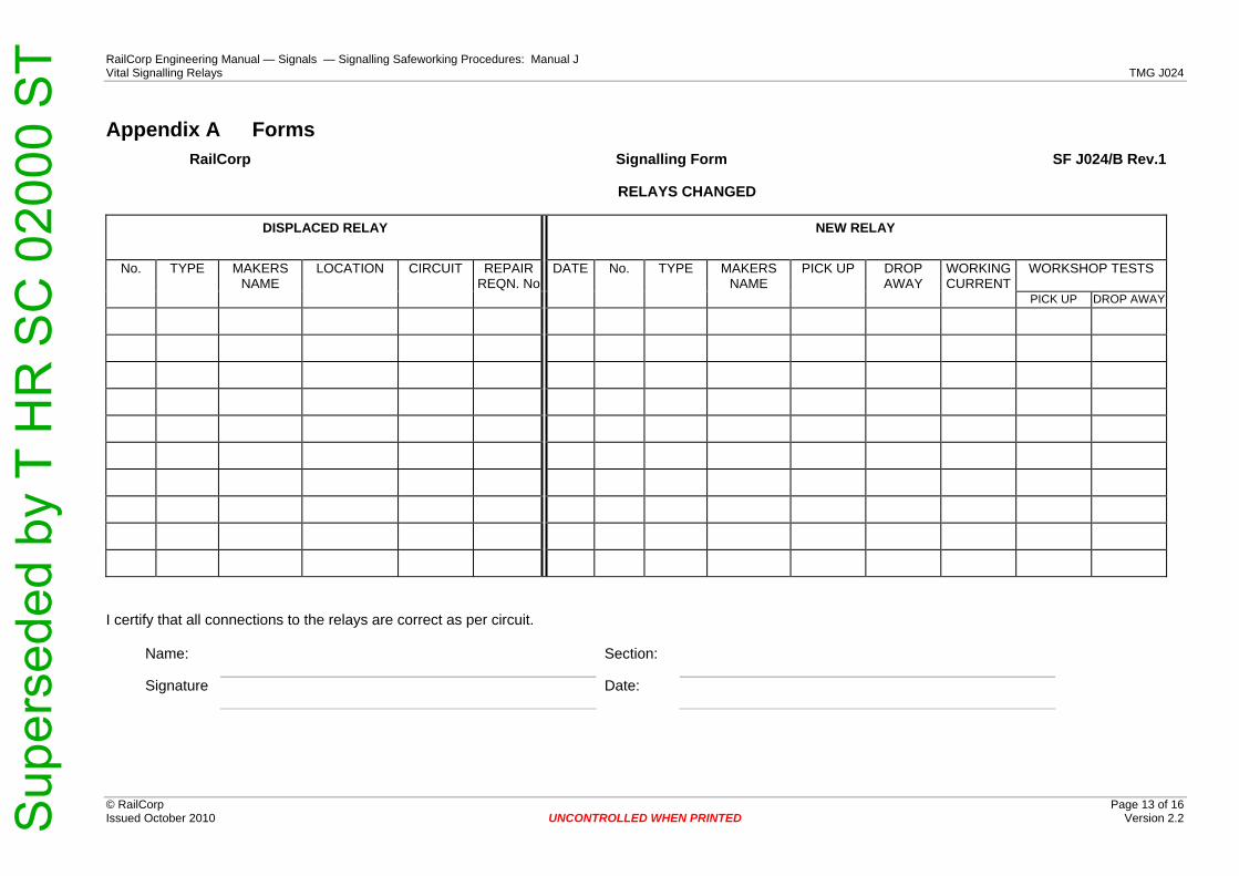
ering Manual — Signals — Signalling Safeworking Procedures: Manual J ys TMG J024
© RailCorp Page 13 of 16 Issued October 2010 Version 2.2
DISPLACED RELAY
NEW RELAY
No. TYPE MAKERS NAME
LOCATION CIRCUIT REPAIRREQN. No
DATE No. TYPE MAKERS NAME
PICK UP DROP AWAY
WORKINGCURRENT
WORKSHOP TESTS
PICK UP DROP AWAY
Appendix A Forms RailCorp Signalling Form SF J024/B Rev.1
RELAYS CHANGED
Name: Section:
Signature Date:
UNCONTROLLED WHEN PRINTED
I certify that all connections to the relays are correct as per circuit.
RailCorp EngineVital Signalling Rela
Sup
erse
ded
by T
HR
SC
020
00 S
T

RailCorp Engineering Manual — Signals — Signalling Safeworking Procedures: Manual J Vital Signalling Relays TMG J024
© RailCorp Page 14 of 16 Issued October 2010 UNCONTROLLED WHEN PRINTED Version 2.2
RailCorp Signalling Form SF J024/C Rev.1
2 YEARLY TEST OF ELECTROMECHANICAL OR THERMAL TIMING RELAYS
MONTH SECTION
CIRCUIT NAME RELAY TYPE TIME SETTING (DESIGN)
TESTED TIME (ACTUAL)
Name: Section:
Signature Date:
Sup
erse
ded
by T
HR
SC
020
00 S
T

RailCorp Engineering Manual — Signals — Signalling Safeworking Procedures: Manual J Vital Signalling Relays TMG J024
© RailCorp Page 15 of 16 Issued October 2010 UNCONTROLLED WHEN PRINTED Version 2.2
Rail Corporation New South Wales Signals Engineering Engineering Division Locked Bag 25 Haymarket NSW 1238 Asset Management Group Level 12, 477 Pitt Street Sydney NSW 2000 RailCorp
Notice of Installation of Shelf Relay Conversion Unit
To Documentation Manager, Signals Engineering, Lvl 12, 477 Pitt St, Sydney, DX 7000RS
Cc
From (Name)
Signal Engineer
Date
Location
Details of Relays changed:
Date Location Relay Name Old Type New Type Changed by
Name: Signature
Sup
erse
ded
by T
HR
SC
020
00 S
T
RailCorp Engineering Manual — Signals — Signalling Safeworking Procedures: Manual J Vital Signalling Relays TMG J024
© RailCorp Page 16 of 16 Issued October 2010 UNCONTROLLED WHEN PRINTED Version 2.2
This page has been intentionally left blank
Sup
erse
ded
by T
HR
SC
020
00 S
T

TMG J025
Manual
TMG J025 Track Circuits
Version 2.5 Issued Date: 22 January 2014 Effective Date: 22 January 2014 to 21 January 2015
Important Warning
This document is one of a set of standards developed solely and specifically for use on the rail network owned or managed by the NSW Government and its agencies. It is not suitable for any other purpose. You shall not use or adapt it or rely upon it in any way unless you are authorised in writing to do so by a relevant NSW Government agency.
If this document forms part of a contract with, or is a condition of approval by, a NSW Government agency, use of the document is subject to the terms of the contract or approval.
This document may not be current. Current standards are available for download from the Asset Standards Authority website at www.asa.transport.nsw.gov.au.
© State of NSW through Transport for NSW Page 1 of 31 Sup
erse
ded
by T
HR
SC
020
00 S
T

TMG J025 TMG J025 Track Circuits
Version 2.5 Effective Date: 22 January 2014 to 21 January 2015
© State of NSW through Transport for NSW Page 2 of 31
Document Control
Version Date Summary of change 1.0 September
2005 Replaced SC 00 52 00 25 SI Track Circuits
1.1 3 March 2010 Minor change to section 2.3 re: test for voltage drop across Audio Frequency track lead connections
1.2 May 2010 Application of TMA 400 format 2.0 November 2010 Moved references of rerailing and contaminated (rusty) rails to TMG
J007 & J026 of Signalling Safeworking Procedures Manual J. Added current balance test for side-lead cables (50Hz acDR) and rearranged bullet points in 2.3 Added additional column in Table 1 to commensurate with notation Added Drop Shunt test in 2.6c
2.1 August 2011 Polarity testing requirement moved to 2 years Section 2.7 Impedance Bond - Annual Maintenance incorporated into 2.5.1 Annual Inspections and Tests and delete Siemens DD131 impedance bond additional task requirement.
2.2 October 2012 Amend section 2.3 (f) to replace the words 'detonator cases' with "other metallic items". Remove requirement for testing spark gaps during normal track circuit maintenance. Included paragraph numbering in 2.3 for paragraphs L to P.
2.3 November 2012 Added FS2600 Train Shunt Check and Zero Feed Value in Table 1 2.4 April 2013 Clarified requirements for maintenance of traction bonding in
section 2.4. 2.5 January 2014 Content rearranged to read in a logical sequence, includes
swapping positions of Tables 1 & 2 such to be located with their relevant text.
Changes made to periodic Inspection, Test & Maintenance tasks and titles to align with new TMP requirements.
Shunt value of AF tracks now all 0.15ohms. FS2600 Zero Feed value in Table 2 (column 5) changed from
>150mV to >100mV ac (Consistent with THC & TMG E1631. Acceptable value of <500mV in column 4 retained)
FS2600 minimum Shunt value added in Table 1 Deleted references to dc track circuits. Emphasised importance & enhanced description of Zero Feed &
Polarity tests, as well as inspection requirements for Parallel Bonds.
Added THC for Microtrax (from TMG J037) Added THC for FS2600 (from TMG E1631) Reformatted into ASA template **Please read the procedure in its entirety**
For queries regarding this document
www.asa.transport.nsw.gov.auSup
erse
ded
by T
HR
SC
020
00 S
T

TMG J025 TMG J025 Track Circuits
Version 2.5 Effective Date: 22 January 2014 to 21 January 2015
© State of NSW through Transport for NSW Page 3 of 31
Table of contents
1. Introduction .......................................................................................................................................4 2. Track circuit test and examination..................................................................................................4 2.1 Track circuit test records (track circuit history cards)..................................................................4 2.2 Shunt tests.........................................................................................................................................5 2.3 Polarity test........................................................................................................................................8 2.4 Zero feed test.....................................................................................................................................9 2.5 Inspection of traction bonding ........................................................................................................9 2.6 Inspection of parallel bonds ..........................................................................................................10 3. Precautions Associated with Track Circuits ................................................................................11 3.1 Adjusting Track Circuits.................................................................................................................11 3.2 50 Hz ac track circuits – circulating currents...............................................................................12 3.3 Interference/repairs to track circuit wires ....................................................................................12 3.4 Contaminated (rusty) rails..............................................................................................................13 3.5 Excessive sanding of the track by locomotives ..........................................................................13 3.6 Inserting CSEE and Jeumont Schneider track circuit receivers................................................13 4. Periodic inspection, test and maintenance tasks........................................................................14 4.1 Safety inspection of double rail 50Hz ac track circuits...............................................................14 4.2 Level one inspection, test and maintenance................................................................................14 4.3 Level two inspection, test and maintenance................................................................................16 4.4 Level three inspection, test and maintenance .............................................................................17 4.5 Other circumstances requiring testing.........................................................................................18
Sup
erse
ded
by T
HR
SC
020
00 S
T

TMG J025 TMG J025 Track Circuits
Version 2.5 Effective Date: 22 January 2014 to 21 January 2015
© State of NSW through Transport for NSW Page 4 of 31
1. Introduction Signalling Maintainers are responsible for maintaining track circuits for safe and reliable
operation.
Signalling Maintainers shall perform, as a minimum, the periodic inspection, test and
maintenance tasks as described in this procedure and at frequencies specified below:
for 'Safety Critical' and 'Safety Significant' tasks – as stipulated in this procedure
where not stipulated in this procedure – frequencies as stipulated in the approved
Technical Maintenance Plan
Additionally, Signalling Maintainers shall be vigilant for potential track circuit problems whenever
the opportunity permits.
Track circuit inspection, test and maintenance requirements include five specific tasks:
examination of all track circuit components, as applicable including: power supplies,
transmitter or feed unit, receiver, track and ballast condition, insulated joints, relay, wiring,
lightning protection, track leads, bonding and connections
recording of track circuit voltages, currents and settings
shunt tests including train shunt test (where necessary)
polarity test (where applicable)
zero feed test
Signalling Maintainers shall make themselves aware of the relevant equipment manuals and
specifications for each type of track circuit which they are required to maintain.
2. Track circuit test and examination The objective of testing and examining track circuits is to find and remove any potential failure
condition, and ensure as far as possible, that the track circuit will function safely and
satisfactorily until the next scheduled examination.
Any condition found with the potential to reduce the reliability of the track circuit shall be
actioned immediately if practicable, or otherwise brought to the notice of the Maintenance
Signal Engineer and dealt with as soon as possible.
Any condition found with the potential to cause a wrong side failure shall be actioned
immediately, and the Maintenance Signal Engineer notified accordingly.
2.1 Track circuit test records (track circuit history cards) Track circuit test records (track circuit history cards) shall be kept near each track relay and
tests shall be recorded thereon. Sup
erse
ded
by T
HR
SC
020
00 S
T

TMG J025 TMG J025 Track Circuits
Version 2.5 Effective Date: 22 January 2014 to 21 January 2015
© State of NSW through Transport for NSW Page 5 of 31
Although preferable to have one card per track circuit located in the track relay location, it is
permissible to have a second card in the track feed location and the test readings recorded
separately for each end of the track circuit on the respective card.
The track circuit history card provides a past record of the performance of the track circuit.
Further to highlighting variations that need to be accounted for, observation and comparison of
values recorded provides a way of detecting trends in performance, allowing problems to be
detected before they cause a failure. Gradual consistent variations (e.g.: adjusting KRV upward
on a CSEE receiver by a small amount each visit) indicate the deterioration of some component
of the track circuit. The causes of these problems shall be identified and resolved.
When a track circuit history card is completely filled up, enter on the first lines of the new card,
the details of the first (full row) test record and last (full row) test record from the old card,
including the respective test dates. This provides a long term base-line against which to
compare changes.
The following shall be treated as a separate track circuit and tests and records carried out and
kept accordingly:
pin-point detectors (DPUs)
centre-fed track circuits
common transmitter track circuits
double-receiver track circuits
cut-section track circuits
Track history cards included at the end of this procedure are
indicative samples only.
2.2 Shunt tests Shunt tests using test resistors require two people, one to apply the shunt resistor and the other
to observe the contacts of the relay.
Shunt checks, using a train or fixed shunt resistor, may be performed by one person checking
that the track relay has dropped when the track is shunted.
The minimum shunt resistance for the relevant track circuit type shall be in accordance with the
value specified in Table 1.
2.2.1 Drop shunt test
The drop shunt resistance is the highest value of resistance which, when placed across the
rails, will cause the relay to drop away (i.e. become de-energised with all front contacts open).
The drop shunt resistance is measured using a variable shunt device called a shunt box.
Sup
erse
ded
by T
HR
SC
020
00 S
T

TMG J025 TMG J025 Track Circuits
Version 2.5 Effective Date: 22 January 2014 to 21 January 2015
© State of NSW through Transport for NSW Page 6 of 31
When taking the drop shunt measurement, the leads of the shunt box are connected across the
rails at the relay/receiver end of the track, set at a high value (at which the relay is energised),
and then the resistance is decreased until the relay drops away; the drop shunt value is then
measured.
The drop shunt test is repeated three times until consistent results are obtained. This result
shall then be recorded on the track circuit history card.
The drop shunt value obtained during initial track circuit set-up or subsequent adjustment shall
be in accordance with the set to work manual for the relevant track circuit type. In any case, the
drop shunt resistance value shall not be less than the value specified in Table 1 for the relevant
track circuit type.
2.2.2 Fixed shunt test
A fixed shunt test is carried out by connecting a resistive shunt across the rails and observing
that the track relay de-energises. Special shunt boxes are available for this purpose.
The value of the resistive shunt used for this test shall be in accordance with the specified
resistance for the relevant track circuit type in Table 1
The shunt resistor shall be connected across the rails at all extremities of the track circuit
(including within crossovers) and at the mid point of the track circuit. At each point the track
relay shall be observed to de-energise.
Table 1 - Minimum Shunt Resistance
Track Circuit Type Minimum Shunt Resistance
Jeumont Schneider impulse track (Double rail) (1xBRTCA2-Rx) 0.25 ohms
Jeumont Schneider impulse track (Double rail) (2xRVT600-Rx) 0.25 ohms
Jeumont Schneider impulse track (Double rail) (1xRVT600-Rx) 0.5 ohms
Jeumont Schneider impulse track (Single rail) (Normal/TV-TH1) 0.5 ohms
Jeumont Schneider impulse track (Single rail) (TV-THD2 or TV-LV) 0.25 ohms
ac track resistor fed - Signal Branch (Single rail) 0.25 ohms
ac track resistor fed – WBS (Single rail) 0.5 ohms
ac track resonant impedance bond 0.25 ohms
ac track AAR standards (Double rail) 0.06 ohms
CSEE audio frequency track 0.15 ohms
ML audio frequency track 0.15 ohms
WB&S audio frequency track (FS2500) 0.15 ohms
Sup
erse
ded
by T
HR
SC
020
00 S
T

TMG J025 TMG J025 Track Circuits
Version 2.5 Effective Date: 22 January 2014 to 21 January 2015
© State of NSW through Transport for NSW Page 7 of 31
Track Circuit Type Minimum Shunt Resistance
WB&S FS2600 0.5 ohms
USS Microtrax 0.25 ohms
2.2.3 Fixed shunt check
If it is necessary only to check that the track circuit will shunt at one point then a fixed shunt
check may be carried out using the fixed shunt resistor described in the fixed shunt test.
2.2.4 Train shunt check
A final test of the proper operation of a track circuit is the train shunt check, carried out to
ensure that there is effective rail/wheel contact and that a train is effectively detected during its
entire passage over the track circuit.
A train shunt check is required where there is doubt about the conductivity of the rail contact
surfaces, for example after re-railing or after an extended period of disuse.
The check is carried out by monitoring the track relay/receiver input voltage, while a train
passes over the whole length of the track circuit, and observing that the input voltage does not
exceed the maximum train shunt value. The test point and the maximum train shunt value for
each type of track circuit are given in Table 2.
Table 2 - Maximum Train Shunt & Zero Feed Values
Track Circuit Type
Test Point
Measure Units
Maximum Train Shunt or Zero Feed Value (see note 1 below)
Advise Maintenance Signal Engineer (see note 2 below)
50 Hz ac Control Terminals V ac <30% of D.A.
test value >10% of D.A. test value
CSEE UM 71 Receiver R1 R2 mV ac with filter <90 mV >30 mV
ML TI 21 Receiver R+ R- mV ac with filter (mV x GAIN) <100
(mV x GAIN) >35
WB&S FS2500 Receiver Monitor mV ac <400 mV >135 mV
Receiver Terminals
Jeumont Schneider C+/C1 (RVT-
600) 3/C1 (BRT-CA2)
V dc with integrator <100 V >35 V
WB&S FS2600 Receiver Monitor mV ac <500 mV >100 mV
Note 1:
Sup
erse
ded
by T
HR
SC
020
00 S
T

TMG J025 TMG J025 Track Circuits
Version 2.5 Effective Date: 22 January 2014 to 21 January 2015
© State of NSW through Transport for NSW Page 8 of 31
This check is best carried out with a Digital Multimeter with an
analogue bar display, set to a fixed voltage range (not auto ranging). On ac vane relays, supply to the local coil will also need to be
opened during the check.
The Drop Away (DA) test value for shelf relays is the drop away
value shown on the manufacturer's or workshop's test label on the relay, and for plug-in relays is the standard drop away value for that
type of relay as shown in the Relays Equipment Manual.
The track circuit shall be disconnected and booked out of use if
maximum train shunt value is exceeded under train shunt conditions.
Note 2:
Notwithstanding the specified maximum train shunt value, test
readings above ten percent of the Drop Away (DA) test value or above one third of the other values specified in Table 2 are to be
further investigated and immediately reported to the Maintenance Signal Engineer.
Note 3:
Where a rail vehicle is fitted with a Track Circuit Actuator (TCA), used to enhance the wheel to rail shunt capability, then the vehicle
cannot be used for a Train Shunt Check unless the TCA is turned off.
2.3 Polarity test A Polarity test is performed to ensure polarities across insulated rail joints of like track circuits
conform to the polarity shown on specific track insulation plan. In most cases the polarity of rail
voltages across insulated rail joints will be opposite. This requirement avoids an unsafe
condition arising, caused by a track circuit being fed from an adjacent track circuit in the event
of an insulated rail joint becoming short-circuit.
The existence of like polarities is only acceptable at a track feed to track feed interface, or
where a short-circuit insulated rail joint would result in both adjacent track circuits becoming de-
energised. Polarity reversal does not apply to audio frequency track circuits.
A Polarity test is performed by checking the rail voltage polarities using a voltmeter (and pulse
integrator where applicable) to ensure that the polarity across all insulated rail joints between
adjacent like track circuits (namely 50Hz ac to 50Hz ac, HV Impulse to HV Impulse and
Microtrax to Microtrax) conform to the specific track insulation plan.
Sup
erse
ded
by T
HR
SC
020
00 S
T

TMG J025 TMG J025 Track Circuits
Version 2.5 Effective Date: 22 January 2014 to 21 January 2015
© State of NSW through Transport for NSW Page 9 of 31
The Maintenance Signal Engineer shall be advised of incorrect polarities between track circuits
as soon as possible. The condition of insulated rail joints shall be checked to ensure they are
not liable to breakdown before the situation is corrected.
The Maintenance Signal Engineer shall consult with a signal design engineer as necessary to
determine appropriate design solutions.
2.4 Zero feed test A Zero Feed test is performed to ensure that the track circuit relay or receiver is not fed from
any other source other than its own track feed or transmitter. The test is generally only required
upon initial certification, or where the work could result in a cross connection of track circuit
feeds, or where there is doubt in regards to the integrity of the track circuit. In any case, a
periodic Zero Feed test shall be performed with a scheduled Level Three Test, Inspection &
Maintenance.
The Zero Feed test requires the track circuit feed or transmitter power supply to be temporarily
disconnected and during this time, the relay voltage or receiver input is measured to be near
zero and does not exceed the maximum Zero Feed values specified in Table 2. The track relay
shall also be observed to have de-energised.
Notwithstanding the specified maximum Zero Feed value, test readings above ten percent of
the Drop Away (DA) test value or above one third of the other values specified in the Table 2
shall be investigated and immediately reported to the Maintenance Signal Engineer.
Note
On ac vane relays, supply to the local coil will also need to be
opened.
On audio frequency track circuits, the transmitter for the track
adjacent to the receiver will also have to have the supply fuse removed unless a frequency selective voltmeter is used.
2.5 Inspection of traction bonding TMG J027 shall also be referenced for Traction Bonding.
Traction bonding includes parallel bonds between rails, tie-in bonds, cross bonds (rail to rail and
rail to impedance bond), and traction bonds from rails to section hut or substation busbars.
Signalling Maintainers shall ensure that traction bonding is in good condition, that open circuit
bonds are immediately replaced, that high resistance connections are immediately rectified, and
that deteriorated bonds are programmed for timely renewal.
Sup
erse
ded
by T
HR
SC
020
00 S
T
TMG J025 TMG J025 Track Circuits
Version 2.5 Effective Date: 22 January 2014 to 21 January 2015
© State of NSW through Transport for NSW Page 10 of 31
Signalling Maintainers shall check the integrity of the traction bond during maintenance visits.
Where traction bonds are visible throughout their entire length, an observation shall be sufficient
to check their integrity. Where traction bonds are buried, the integrity shall be checked using a
clamp meter on each parallel leg of the traction bond to ensure they are all carrying equal
current.
(Generally, series traction bonds to substations, etc, are buried, and parallel traction bonds are surface run).
2.6 Inspection of parallel bonds Parallel bonds on track circuits extending over points to a clearance point on another line, shall
be inspected at a frequency not exceeding three months. Where parallel bonds are surface run,
have hypalon insulation and welded rail connections, then the inspection frequency can be
extended to six month intervals. However, Signalling Maintainers shall take the opportunity to
inspect parallel bonds whenever opportunities arise (i.e. working in the vicinity of the points).
The inspection of parallel bonds is to ensure the bonding has not been damaged or removed by
track work, or vandals, copper thieves, etc, which could result in loss of train detection.
Sup
erse
ded
by T
HR
SC
020
00 S
T
TMG J025 TMG J025 Track Circuits
Version 2.5 Effective Date: 22 January 2014 to 21 January 2015
© State of NSW through Transport for NSW Page 11 of 31
3. Precautions Associated with Track Circuits 3.1 Adjusting Track Circuits
On installation, adjust the track circuit and complete all entries shown on the track circuit history
card.
Adjust track circuits with the track bonding (rail bonds, series bonds, parallel bonds,
impedance bond side leads) and rail connections in good condition with low resistance
Track circuit feed voltages shall not be increased to compensate for open circuit or
high resistance bonding. In electrified areas, high track feed voltages could
increase the probability of circulating currents through traction tie in bonding or
earths
Adjust track circuits and perform Drop Shunt tests preferably in dry ballast conditions.
Track circuits adjusted in wet or poor ballast conditions shall be retested when the track
has dried out, or the ballast conditions improved, to ensure correct shunting
the Maintenance Signal Engineer shall be informed of planned works or activities
which could change track or ballast conditions and affect the proper adjustment of
the track circuit and its ability to operate reliably and safely
signalling Maintainers are permitted to make minor adjustments but the
Maintenance Signal Engineer shall be promptly informed
intended large adjustments or adjustments required for unaccountable reasons
shall be immediately reported to the Maintenance Signal Engineer for instructions
Whenever the track circuit is readjusted, measure and record all track circuit voltage readings
on the track history card; perform a Fixed Shunt Test at all extremities and observe the relay
pick up and drop away correctly. Also perform a Drop Shunt test at the relay/receiver end.
The Signalling Maintainer shall regularly monitor the track circuit and the track shall be
readjusted immediately the ballast conditions have improved. The Maintenance Signal Engineer
shall ensure the timely correction of the adjustment.
Whenever a track circuit is adjusted an entry shall be made, stating the reason for the
adjustment, on the track circuit history card.
Sup
erse
ded
by T
HR
SC
020
00 S
T
TMG J025 TMG J025 Track Circuits
Version 2.5 Effective Date: 22 January 2014 to 21 January 2015
© State of NSW through Transport for NSW Page 12 of 31
3.2 50 Hz ac track circuits – circulating currents Where a fault condition causes 50 Hz ac track circuit currents to circulate via traction tie-in
bonds or earths, etc through other track circuits (or where a fault condition causes ac currents in
the dc traction supply) then a potentially unsafe condition can occur if a high resistance track
circuit condition arises. All cases of open circuit or high resistance rail bonds, series bonds,
impedance bond side leads, and their connections, shall be rectified promptly. Emergency
jumper bonds, in good condition and correctly applied, should be utilised as required but
replaced by permanent bonds as soon as possible. Any case where ac rail current unbalance is
detected shall be immediately reported to the Maintenance Signal Engineer, and the cause
found and rectified without delay.
The rail current balance of double rail 50 Hz ac track circuits shall be determined by measuring
the signalling current in both rails, at both the feed and relay ends of the track, using an
Induction meter. This test is not highly accurate, due to variations induced by traction current
harmonics; however the test does give a convenient indication of unbalance in the rail currents,
and any difference greater than 0.5 A shall be considered significant.
Measuring rail current balance using a meter that is not 50 Hz frequency selective may not be
an accurate indicator because of traction harmonics flowing in the traction rail. Differences
between the rail currents measured on an induction meter of greater than 1.25 A on single rail
50 Hz ac track circuits should be further investigated by checking other track circuits in the
vicinity.
While there should not be any stray 50 Hz currents emanating from balanced double rail track
circuits, this is not the case with single rail 50 Hz ac track circuits, where close tie in bonding
between the traction rails of parallel tracks provides an alternate low resistance path for stray
50 Hz ac track circuit currents. It may not then be unusual to measure unbalanced 50 Hz
currents in single rail track circuits.
A special periodic inspection is required to be scheduled as described in section 4.1. This
inspection is categorised as 'Safety Critical'.
3.3 Interference/repairs to track circuit wires Whenever two or more track circuit wires are disconnected and reconnected or repairs are
made to two or more broken wires to or from track circuit equipment, ensure that the track relay
has picked up and perform a Fixed Shunt check or Train Shunt check to ensure that it drops
away correctly. Where applicable, perform a Polarity test between the affected track circuit and
adjacent track circuits if there is any possibility of the track circuit polarity being altered.
Sup
erse
ded
by T
HR
SC
020
00 S
T

TMG J025 TMG J025 Track Circuits
Version 2.5 Effective Date: 22 January 2014 to 21 January 2015
© State of NSW through Transport for NSW Page 13 of 31
3.4 Contaminated (rusty) rails Signalling Safeworking Procedure TMG J007 Apparatus Seldom Used shall be referenced for
matters relating to the management of contaminated (rusty) rail caused by track circuits seldom
used.
Signalling Safeworking Procedure TMG J026 Rerailing – Precautions to be Taken shall be
referenced for matters relating to the certification of track circuits following a rerailing.
3.5 Excessive sanding of the track by locomotives When excessive sanding of tracks occurs in track circuited areas the effective shunting of track
circuits could be affected.
Any case of excessive sanding is to be immediately brought to the attention of the Maintenance
Signal Engineer, and also to the attention of the driver and/or nearest Signaller. Network control
personnel shall issue a Network Incident Notice (NIN) as per NGE 214, to report the instance of
excessive sanding.
Any instances of trains failing to shunt track circuits, intermittently or otherwise due to sand on
the rail head, are to be immediately reported to the Maintenance Signal Engineer and fully
investigated.
3.6 Inserting CSEE and Jeumont Schneider track circuit receivers It is critical that CSEE and Jeumont Schneider track circuit receivers are plugged into their
correct rack positions. The misalignment of a receiver by one module space can have unsafe
consequences, resulting in the permanent energisation of the track relay.
To prevent this occurrence, Signalling Maintainers shall ensure that these units are replaced
into their correct position whenever they are unplugged from their base, and additionally check
on all racking used for CSEE and Jeumont-Schneider track circuit equipment, that every vacant
module position above and below these units is fitted with obturation fittings and coding plugs.
Sup
erse
ded
by T
HR
SC
020
00 S
T

TMG J025 TMG J025 Track Circuits
Version 2.5 Effective Date: 22 January 2014 to 21 January 2015
© State of NSW through Transport for NSW Page 14 of 31
4. Periodic inspection, test and maintenance tasks 4.1 Safety inspection of double rail 50Hz ac track circuits
The following schedule of tasks is categorised as 'Safety Critical' and shall be performed at a frequency not exceeding one month.
Test double rail 50Hz ac track circuits in electrified areas as follows, and record the results on the Safety Inspection Track History Card:
track relay coil voltage, unoccupied
current in each rail, relay end, for balance
current in each rail, feed end, for balance
current in each cable of impedance bond side lead, up rail, for balance
current in each cable of impedance bond side lead, down rail, for balance
voltage drop across side lead connection to the up rail
voltage drop across side lead connection to the down rail
The track circuit shall be adjusted so the relay coil voltage reads approximately 50% (under normal working conditions) above the working/compression voltage shown on the relay's workshop label.
The current in each rail at the one location should be equal or within 0.5 A as measured on an induction meter.
Investigate unbalance (unequal) current readings and advise the Maintenance Signal Engineer without delay.
The currents measured in each cable of a side lead pair of cables should be equal, or within 10%. Uneven current sharing indicates a high resistance side lead or connection.
The voltage drop across a side lead connection to the rail should be less than 10 mV ac.
Investigate changes in values significantly different to previous readings.
4.2 Level one inspection, test and maintenance The following schedule of tasks shall be performed at a frequency in accordance with the approved Technical Maintenance Plan.
The following tasks shall be performed as part of this scheduled maintenance:
examine connections to the rails and the condition of cables for:
track circuit leads (shall include testing to ensure that the voltage drop across all
Audio Frequency track lead connections to rail head be of low resistance)
parallel bonds
series bonds
Sup
erse
ded
by T
HR
SC
020
00 S
T

TMG J025 TMG J025 Track Circuits
Version 2.5 Effective Date: 22 January 2014 to 21 January 2015
© State of NSW through Transport for NSW Page 15 of 31
mechanical fishplate bonds
electrolysis bonds
impedance bond side leads
traction tie-in leads
emergency jumper bonds
The voltage drop across impedance bond side lead connections to the bond and to the rail shall
be checked to be low resistance, i.e.; less than 10 mV ac.
examine connections to air-cored inductors, tuning units, compensating capacitors and
their connections
examine cable fasteners to rails and sleepers (including clip/cleating arrangements on
concrete sleepers)
examine insulated rail joints for:
deterioration.
rail burning/burring over
steel scale
clear of ballast and metallic items
using an induction meter, check the leakage through the insulated joints
where an insulated joint between track circuits is in need of repair, check for correct
polarity reversal as a precautionary measure
examine point rods, signal wires and debris such as spent drink cans or other metallic
items coming into contact with rails and crossing noses
check that traction bonding cables and other cables are clear of, and insulated from, rails
to which they are not bonded
check for rusty rails, sand or other contamination which could affect train shunts (on the
contact surface of the rail)
check that rail fasteners (including Pandrol clips) are clear of fishplate bolts at insulated
joints, and clip and chair insulation pads on concrete sleepered track. Rail fasteners and
rail bonds clear of steel structure on bridges
check the general condition of ballast
examine lightning protection equipment
Sup
erse
ded
by T
HR
SC
020
00 S
T

TMG J025 TMG J025 Track Circuits
Version 2.5 Effective Date: 22 January 2014 to 21 January 2015
© State of NSW through Transport for NSW Page 16 of 31
record the voltage at the track receiver/relay and check against the last recorded value
on 50 Hz ac track circuits, check and record the rail current balance
observe the track relay pick up and drop away operation where practical, when the track
circuit is shunted by a train
If the reading shows a variation from the last recorded value which is large enough that it cannot
be accounted for by normal variations in ballast conditions, then further investigation and tests
shall be carried out. Severe degradation of performance of the track circuit outside normal
behaviour or known symptoms of failure shall be reported to the Maintenance Signal Engineer
who shall arrange an investigation.
4.3 Level two inspection, test and maintenance In addition to the schedule of tasks listed above, the following schedule of tasks shall be
performed (as applicable) at a frequency in accordance with the approved Technical
Maintenance Plan.
Note: Level Two Inspection, Test & Maintenance tasks have been split across service schedules 1 and 2 of the approved technical maintenance plan.
impedance bonds fitted with removable lids which are installed inside the track below top
of sleeper level shall be internally inspected for wear and damage. The set screws
securing the yoke to the laminated core and all terminal studs shall be kept tight. The
windings shall be examined to ensure that the insulation is not displaced and that the coil
leads are not fractured. The bond shall be examined to see that it is clean and dry and
the case is not cracked. When replacing the lids of bonds installed in the four foot it is
essential that the sealing of the connection inlets and hemp lid packing or gasket will
effectively exclude the entry of water or other foreign matter. The set screws or bolts
securing the lid shall be kept in good order and the wooden packing, where provided,
maintained in position.
Impedance bonds installed on the outside of the track (on stands), or otherwise have fixed lids, do not require periodic internal
inspection.
Jeumont Schneider CIT 1400 impedance bonds can suffer from loose back nuts so
particular attention should be given to any loose terminations. The construction of this
bond brings out each half of the winding externally for traction connections. To prevent a
possible cause for unbalanced traction return a good solid connection shall be maintained
between the two centre copper bars. Inspect this connection to ensure that the two bus
bars form a good connection.
Sup
erse
ded
by T
HR
SC
020
00 S
T

TMG J025 TMG J025 Track Circuits
Version 2.5 Effective Date: 22 January 2014 to 21 January 2015
© State of NSW through Transport for NSW Page 17 of 31
on MJS and ABW 1000 amps per rail impedance bonds, the condition of the connections
is to be examined for looseness or any signs of oxidisation
on 2000 amps per rail impedance bonds there is an additional box mounted on the rear of
the bond containing either capacitors (2000R and 2000RAF) or a transformer (2000P).
The lid on the box is to be removed and a check made for any loose or imperfect
connections.
on resonated bonds the capacitor voltage is to be measured and recorded on the
respective impedance bond capacitor history card. Variation in the voltage compared to
previous records is to be investigated.
Signalling Maintainers shall also ensure that whenever a refurbished impedance bond is being
installed, an internal inspection is carried out to ensure that it has suffered no damage or
deterioration (e.g. damaged caused during storage or transport).
4.4 Level three inspection, test and maintenance The following schedule of tasks is categorised as Safety Significant. These tasks shall be
performed, in addition to the schedule of tasks listed above, at a frequency not exceeding two
years.
measure all voltage readings indicated on track circuit history card according to the
method prescribed for each track circuit type and record the results on a new line on the
card and compare with previous results
perform a Fixed Shunt test, with the appropriate resistance value for the type of track
circuit concerned (see Table 1), at all extremities of the track circuit including in points
turnouts and crossovers and especially where connected by parallel bonding. Record
details on the track history card.
if the track fails to shunt at the minimum shunt value specified for that type of track circuit,
then a Drop Shunt test shall be conducted and the Signal Engineer shall be informed
immediately. The track circuit shall not be left operating in an unsafe condition.
on compensated track circuit types, record the rail-rail voltage at each capacitor
connection and compare with previous results
on 50 Hz ac and high voltage impulse track circuits, perform a polarity test across all
insulated rail joints between adjacent track circuits of the same type, including at all
extremities where there are turnouts and crossovers. Ensure track polarities conform to
the specific track insulation plan
where adjacent track circuits of the same type are fed from different power supplies, then
ensure these supplies are operating on the Normal supply during the polarity test
advise any discrepancies to the Maintenance Signal Engineer
Sup
erse
ded
by T
HR
SC
020
00 S
T

TMG J025 TMG J025 Track Circuits
Version 2.5 Effective Date: 22 January 2014 to 21 January 2015
© State of NSW through Transport for NSW Page 18 of 31
insulation test track circuit leads from the location to the bootleg riser, bond or tuning unit,
and record values, every two years for non PVC insulated cables and every four years for
PVC insulated PVC sheathed cables.
on all track circuit types, perform a zero feed test.
If the track circuit readings show variations from the last recorded values which are large
enough that they cannot be accounted for by normal variations in ballast condition, then further
investigation shall be carried out. Severe degradation of performance of the track circuit outside
normal behaviour or known symptoms of failure shall be reported to the Maintenance Signal
Engineer for investigation.
4.5 Other circumstances requiring testing Non periodic inspection, test and maintenance are required whenever there are events that may
cause change(s) which could affect adjustment, polarity, etc and thus impair the safe and
reliable operation of track circuit.
in the case of 50 Hz ac track circuits with shelf relays, when a relay change has been
carried out. Perform a Fixed Shunt Check at the relay and measure the relay voltage
before and during the fixed shunt check. Compare the values with previous values, the
track relay workshop test values, and the normally required values. Assess the need for
readjustment.
following replacement of equipment items forming part of the track circuit has been
changed, e.g.: transformer, resistor, impedance bond, capacitor, transmitter, receiver,
tuning unit, matching unit, shielding unit. Perform a Drop Shunt test at the relay/receiver-
end to determine the value of shunt resistance required to shunt the track circuit. Also
perform a Fixed Shunt Check at the relay/receiver-end and measure the relay/receiver
voltage before and during the fixed shunt check. Compare the values with the previous
values, the track relay workshop test values and the normally expected values. Assess
the need for readjustment.
following track work such as relaying or ballast cleaning that has the potential of affecting
the adjustment of the track circuit. Perform a Fixed Shunt Check at the relay end and
measure the relay/receiver voltage before and during the fixed shunt check. Compare the
values with the previous values, the track relay workshop test values and the normally
required values. Assess the need for readjustment.
when track circuit readjustment is required proceed as stipulated in section 3.1. When a
track circuit is readjusted a Drop Shunt test is also required as well as a Fixed Shunt test
at all extremities.
whenever both track circuit feed wires and relay wires are disconnected and reconnected,
perform Polarity tests between adjacent track circuits requiring polarity reversal.
Sup
erse
ded
by T
HR
SC
020
00 S
T

TMG J025 TMG J025 Track Circuits
Version 2.5 Effective Date: 22 January 2014 to 21 January 2015
© State of NSW through Transport for NSW Page 19 of 31
whenever track circuit feed wires or relay wires have been reconnected, or a 50 Hz ac
track feed transformer has been changed, the track relay shall be observed to pick up
correctly to ensure that there has been no change to the circuit polarity
whenever the polarity of power supply transformers or wiring feeding the track circuits is
subject to change, perform Polarity tests between adjacent track circuits requiring polarity
reversal which are fed from different power supplies
when investigating no cause found failures or repeat failures, testing shall be performed
in accordance with guidelines or as instructed by the Maintenance Signal Engineer or as
otherwise deemed required to eliminate any potential cause
Whenever a track circuit is newly installed, a full suite of tests shall be performed in
accordance with the relevant track circuit set to work manual.
following an incident, perform specific tests as directed by the investigating Signal
Engineer
Sup
erse
ded
by T
HR
SC
020
00 S
T
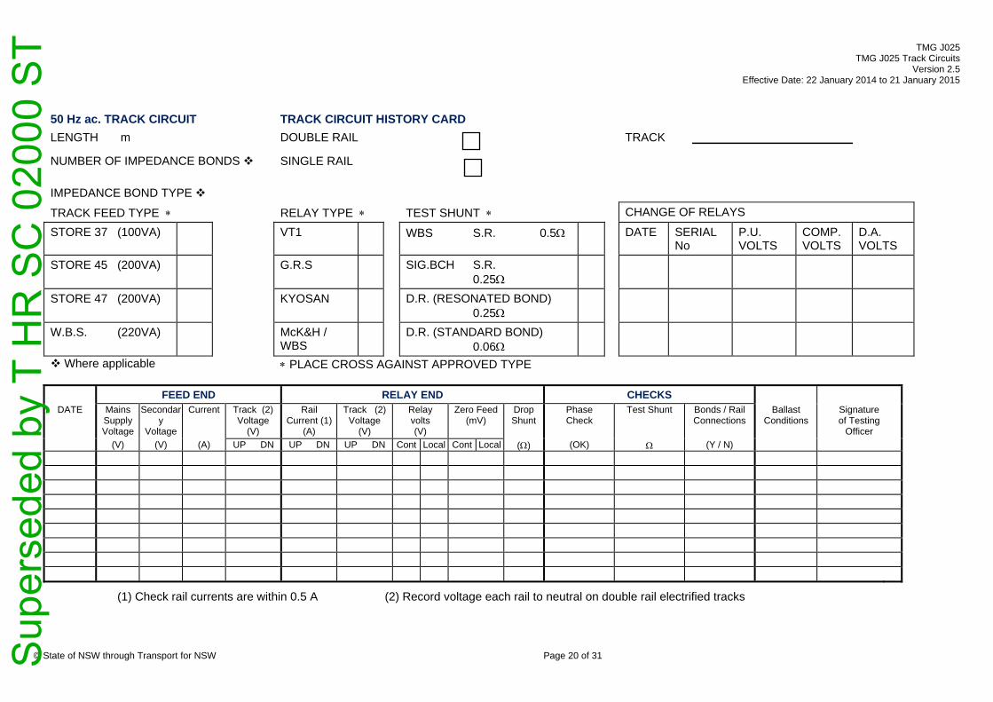
TMG J025 TMG J025 Track Circuits
Version 2.5 Effective Date: 22 January 2014 to 21 January 2015
50 Hz ac. TRACK CIRCUIT TRACK CIRCUIT HISTORY CARD LENGTH m DOUBLE RAIL TRACK
NUMBER OF IMPEDANCE BONDS
SINGLE RAIL
IMPEDANCE BOND TYPE
TRACK FEED TYPE RELAY TYPE TEST SHUNT CHANGE OF RELAYS
STORE 37 (100VA) VT1 WBS S.R. 0.5 DATE SERIAL No
P.U. VOLTS
COMP.VOLTS
D.A. VOLTS
STORE 45 (200VA) G.R.S SIG.BCH S.R. 0.25
STORE 47 (200VA) KYOSAN D.R. (RESONATED BOND) 0.25
W.B.S. (220VA) McK&H / WBS
D.R. (STANDARD BOND) 0.06
Where applicable PLACE CROSS AGAINST APPROVED TYPE
FEED END RELAY END CHECKS DATE Mains
Supply Voltage
Secondary
Voltage
Current
Track (2) Voltage
(V)
Rail Current (1)
(A)
Track (2) Voltage
(V)
Relay volts (V)
Zero Feed (mV)
DropShunt
Phase Check
Test Shunt
Bonds / Rail Connections
Ballast Conditions
Signature of Testing
Officer (V) (V) (A) UP DN UP DN UP DN Cont Local Cont Local () (OK) (Y / N)
(1) Check rail currents are within 0.5 A (2) Record voltage each rail to neutral on double rail electrified tracks
© State of NSW through Transport for NSW Page 20 of 31 S
uper
sede
d by
T H
R S
C 0
2000
ST
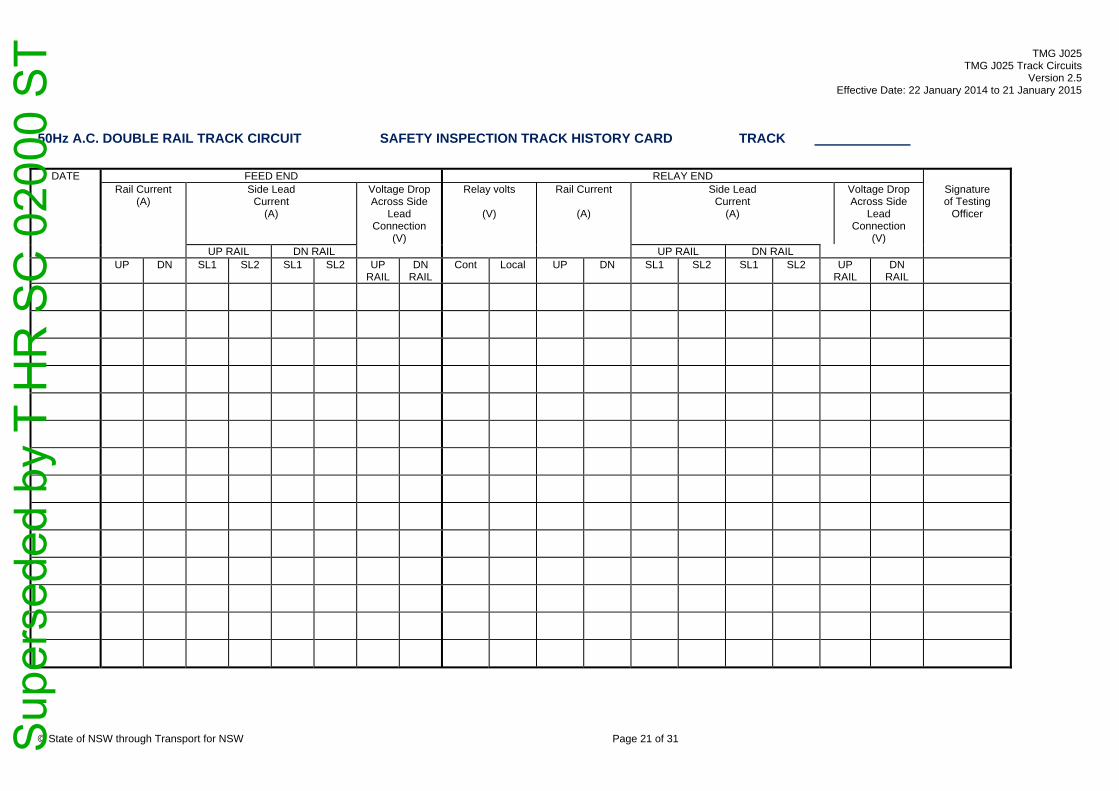
TMG J025 TMG J025 Track Circuits
Version 2.5 Effective Date: 22 January 2014 to 21 January 2015
50Hz A.C. DOUBLE RAIL TRACK CIRCUIT SAFETY INSPECTION TRACK HISTORY CARD TRACK
DATE FEED END RELAY END Rail Current
(A) Side Lead
Current (A)
Voltage DropAcross Side
Lead Connection
(V)
Relay volts
(V)
Rail Current
(A)
Side Lead Current
(A)
Voltage Drop Across Side
Lead Connection
(V)
Signature of Testing
Officer
UP RAIL DN RAIL UP RAIL DN RAIL UP DN SL1 SL2 SL1 SL2 UP
RAIL DN
RAIL Cont Local UP DN SL1 SL2 SL1 SL2 UP
RAIL DN
RAIL
© State of NSW through Transport for NSW Page 21 of 31 S
uper
sede
d by
T H
R S
C 0
2000
ST
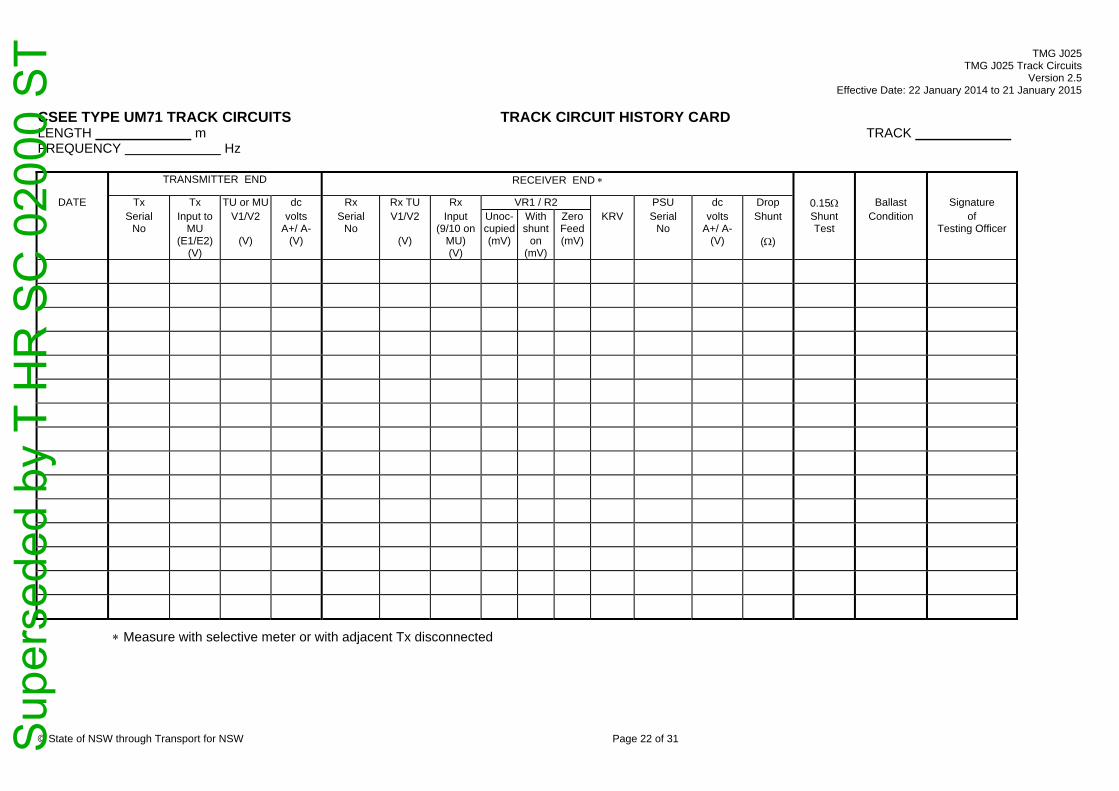
TMG J025 TMG J025 Track Circuits
Version 2.5 Effective Date: 22 January 2014 to 21 January 2015
© State of NSW through Transport for NSW Page 22 of 31
CSEE TYPE UM71 TRACK CIRCUITS TRACK CIRCUIT HISTORY CARD LENGTH m TRACK FREQUENCY Hz
TRANSMITTER END RECEIVER END
DATE Tx Tx TU or MU dc Rx Rx TU Rx VR1 / R2 PSU dc Drop 0.15 Ballast Signature Serial
No Input to
MU (E1/E2)
(V)
V1/V2
(V)
volts A+/ A-
(V)
Serial No
V1/V2
(V)
Input (9/10 on
MU) (V)
Unoc-cupied(mV)
With shunt
on (mV)
Zero Feed(mV)
KRV Serial No
volts A+/ A-
(V)
Shunt
()
Shunt Test
Condition of Testing Officer
Measure with selective meter or with adjacent Tx disconnected
Sup
erse
ded
by T
HR
SC
020
00 S
T
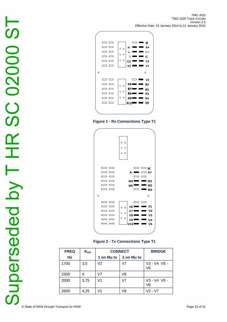
TMG J025 TMG J025 Track Circuits
Version 2.5 Effective Date: 22 January 2014 to 21 January 2015
© State of NSW through Transport for NSW Page 23 of 31
Figure 1 - Rx Connections Type T1
A-
M4 M5
A+
M1 M2 M3
M
V6 V7 V8 V9
V10
V2 V1
V3 V4 V5
Figure 2 - Tx Connections Type T1
FREQ KEM CONNECT BRIDGE Hz 1 on Mu to 2 on Mu to
1700 3,5 V2 V7 V3 - V4 V5 - V6
2300 4 V7 V8 2000 3,75 V1 V7 V3 - V4 V5 -
V6 2600 4,25 V1 V8 V2 - V7
Sup
erse
ded
by T
HR
SC
020
00 S
T

TMG J025 TMG J025 Track Circuits
Version 2.5 Effective Date: 22 January 2014 to 21 January 2015
KRV CONNECT BRIDGE KRV CONNECT BRIDGE KRV CONNECT BRIDGE KRV CONNECT BRIDGE R1 to R2 to R1 to R2 to R1 to R2 to R1 to R2 to
1 R3 R4 20 R9 R4 R3 - R8 39 R10 R5 R3 - R9 58 R10 R7 R4 - R6 R5 - R8
2 R5 R4 21 R9 R8 40 R10 R5 R4 - R9 59 R10 R7 R3 - R6 R5 - R8
3 R3 R5 22 R9 R3 R4 - R8 41 R10 R4 R3 - R9 60 R10 R5 R3 - R8
4 R5 R7 R3 - R6 23 R9 R4 R5 - R8 42 R10 R9 61 R10 R5 R4 - R8
5 R5 R7 R4 - R6 24 R9 R3 R5 - R8 43 R10 R3 R4 - R9 62 R10 R4 R3 - R8
6 R4 R7 R3 - R6 25 R9 R5 R3 - R6 R7 - R8 44 R10 R4 R5 - R9 63 R10 R8
7 R6 R7 26 R9 R5 R4 - R6 R7 - R8 45 R10 R3 R5 - R9 64 R10 R3 R4 - R8
8 R3 R7 R4 - R6 27 R9 R4 R3 - R6 R7 - R8 46 R10 R5 R3 - R6 R7 - R9 65 R10 R4 R5 - R8
9 R4 R7 R5 - R6 28 R9 R6 R7 - R8 47 R10 R5 R4 - R6 R7 - R9 66 R10 R3 R5 - R8
10 R3 R7 R5 - R6 29 R9 R3 R4 - R6 R7 - R8 48 R10 R4 R3 - R6 R7 - R9 67 R10 R5 R3 - R6 R7 - R8
11 R9 R7 R3 - R8 R5 - R6 30 R9 R4 R5 - R6 R7 - R8 49 R10 R6 R7 - R9 68 R10 R5 R4 - R6 R7 - R8
12 R9 R7 R4 - R8 R5 - R6 31 R9 R3 R5 - R6 R7 - R8 50 R10 R3 R4 - R6 R7 - R9 69 R10 R4 R3 - R6 R7 - R8
13 R9 R7 R3 - R8 R4 - R6 32 R10 R7 R5 - R6 R3 - R9 51 R10 R4 R5 - R6 R7 - R9 70 R10 R6 R7 - R8
14 R9 R7 R6 - R8 33 R10 R7 R5 - R6 R4 - R9 52 R10 R3 R5 - R6 R7 - R9 71 R10 R3 R4 - R6 R7 - R8
15 R9 R3 R4 - R7 R6 - R8 34 R10 R7 R4 - R6 R3 - R9 53 R10 R7 R5 - R6 R3 - R8 72 R10 R4 R5 - R6 R7 - R8
16 R9 R4 R5 - R7 R6 - R8 35 R10 R7 R6 - R9 54 R10 R7 R5 - R6 R4 - R8 73 R10 R3 R5 - R6 R7 - R8
17 R9 R3 R5 - R7 R6 - R8 36 R10 R7 R3 - R6 R4 - R9 55 R10 R7 R4 - R6 R3 - R8
18 R9 R5 R3 - R8 37 R10 R7 R4 - R6 R5 - R9 56 R10 R7 R6 - R8
19 R9 R5 R4 - R8 38 R10 R7 R3 - R6 R5 - R9 57 R10 R7 R3 - R6 R4 - R8
© State of NSW through Transport for NSW Page 24 of 31 S
uper
sede
d by
T H
R S
C 0
2000
ST

TMG J025 TMG J025 Track Circuits
Version 2.5 Effective Date: 22 January 2014 to 21 January 2015
WB&S FS2500 TRACK CIRCUITS TRACK CIRCUIT HISTORY CARD TRACK IMPEDANCE BONDS LENGTH m RESONATED Y / N FREQUENCY Hz RES.CAP. nF Tx OUTPUT LEVEL % HI / LO CAP. VOLTS V
TRANSMITTER END DPU RECEIVER END
DATE Tx TU TU PSU dc DPU Amp Amp Rx Rx TU Rx Monitor volts Rx Drop PSU dc 0.15 Ballast Signature Serial
No Input
(V)
T1/T2
(V)
Serial No
(V)
SerialNo
SerialNo
Gain (Hi / Lo)
InputCurren
t (mA)
Serial No
T1/T2
(V)
Input
(V)
Unoc-cupied (mV)
With shunt
on (mV)
Zero Feed(mV)
Sens
Shunt
()
Serial No
(V)
Shunt Check(OK)
Condition of Testing Officer
For Tracks with Intermediate Receivers Only
© State of NSW through Transport for NSW Page 25 of 31 S
uper
sede
d by
T H
R S
C 0
2000
ST

TMG J025 TMG J025 Track Circuits
Version 2.5 Effective Date: 22 January 2014 to 21 January 2015
Receiver sensitivity adjustment table Guide to Tx Output Level Adjustment
Sens Connect Bridge Nominal Track Circuit Length
Tx Output Level
Output Number
Terminals Used
A to B to 50 - 250 m 20% 1 (LO) 1 and 2 1.65 -45 +5 +45 to -15 +15 to -5 250 - 450 m 40% 2 1 and 3 1.60 -45 +15 +45 to -15 450 - 600 m 60% 3 3 and 4 1.55 -45 -5 +45 to -15 +15 to +5 600 - 750 m 80% 4 2 and 4 1.50 -45 +5 +45 to -5 750 - 900 m 100% 5 (HI) 1 and 4 1.45 -45 +45 1.40 -45 -5 +45 to +5 The Screen Terminal is Earthed 1.35 -45 +5 +45 to +15 -15 to -5 1.30 -45 -15 +45 to +15 1.25 -45 -5 +45 to +15 -15 to +5 1.20 -15 +5 +15 to -5 1.15 -15 +15 1.10 -15 -5 +15 to +5 1.05 -5 +5 1.00 B 0.95 +5 -5 0.90 +15 +5 -15 to -5 0.85 +15 -15 0.80 +15 -5 -15 to +5 0.75 +45 +5 -45 to -15 +15 to -5 0.70 +45 +15 -45 to -15 0.65 +45 -5 -45 to -15 +15 to +5 0.60 +45 +5 -45 to -5 0.55 +45 -45 0.50 +45 -5 -45 to +5 0.45 +45 +5 -45 to +15 -15 to -5 0.40 +45 -15 -45 to +15 0.35 +45 -5 -45 to +15 -15 to +5
© State of NSW through Transport for NSW Page 26 of 31 S
uper
sede
d by
T H
R S
C 0
2000
ST

TMG J025 TMG J025 Track Circuits
Version 2.5 Effective Date: 22 January 2014 to 21 January 2015
GEC - ALSTHOM JEUMONT SCHNEIDER
TRACK CIRCUIT HISTORY CARD TRACK
TRACK CIRCUIT TRACK TYPE *
Rx TYPE TOTAL Tx LOOP RES.
TEST SHUNT
RVT600 20 0.5 LENGTH m
DOUBLE RAIL BRTCA2 10 0.25
Tx LOOP RESISTANCE SINGLE RAIL
2 x RVT600 20 0.25
(* Place X next to applicable type)
POWER SUPPLY TRANSMITTER END RECEIVER END DATE PSU
Serial Mains Supply
Tx Serial
Tx Output volts
Track Voltage
Rx Serial
Track Voltage
Rx Input volts
Volts with shunt on Shunt Test
Polarity Check
Ballast Condition
Signature of Testing Officer
No (V)
No C+ / C-
(V)
No (V)
C+ / C2- or
C2+ / C2-
3 / C1-
C+ / C2- or
C2+ / C2-
3 / C1-
Hi Low Hi Low Hi Low Hi Low Hi Low Hi Low Hi Low
© State of NSW through Transport for NSW Page 27 of 31 S
uper
sede
d by
T H
R S
C 0
2000
ST

TMG J025 TMG J025 Track Circuits
Version 2.5 Effective Date: 22 January 2014 to 21 January 2015
TYPE ABB - ML TI 21 TRACK CIRCUITS TRACK CIRCUIT HISTORY CARD TRACK
LENGTH m FREQUENCY Tu INPUT POWER (Hi / Low)
TRANSMITTER END RECEIVER END mV Across 1
DATE Tx Serial
No
Tu Input (V)
Tu T1/T2
(V)
PSU Serial
No
dc volts
(V)
Rx Serial
No
Tu T1/T2
(V)
Rx Input (V)
Unoc-cupied
(mV)
With shunt
on
(mV)
Zero Feed
(mV)
Gain Setting
Drop Shunt Value( )
PSU Serial
No
dc volts
(V)
0.15 Shunt Test
BallastCondition
Signature of
Testing Officer
© State of NSW through Transport for NSW Page 28 of 31 S
uper
sede
d by
T H
R S
C 0
2000
ST

TMG J025 TMG J025 Track Circuits
Version 2.5 Effective Date: 22 January 2014 to 21 January 2015
TRACK
TRANSMITTER END RECEIVER END mV Across 1
DATE Tx Serial
No
Tu Input (V)
Tu T1/T2
(V)
PSU Serial
No
dc volts
(V)
Rx Serial
No
Tu T1/T2
(V)
Rx Input (V)
Unoc-cupied
(mV)
With shunt
on
(mV)
Zero Feed (mV)
Gain Setting
Drop Shunt Value( )
PSU Serial
No
dc volts
(V)
0.15 Shunt Test
BallastCondition
Signature of
Testing Officer
GAIN INPUT WIRING 1 H to Input 1 Bridge Bridge 1 1L 1H 2 3L 1L 1H - 3H 3 3L 3H 4 3L 1H 1L - 3H 5 9L 1L 1H - 3L 3H - 9H 6 9L 3L 3H - 9H 7 9L 1H 1L - 3L 3H - 9H 8 9L 1L 1H - 9H 9 9L 9H 10 9L 1H 1L - 9H 11 9L 1L 1H - 3H 3L - 9H 12 9L 3H 3L - 9H 13 9L 1H 1L - 3H 3L - 9H INPUT 2 is always connected to 1 Low.
© State of NSW through Transport for NSW Page 29 of 31 S
uper
sede
d by
T H
R S
C 0
2000
ST

TMG J025 TMG J025 Track Circuits
Version 2.5 Effective Date: 22 January 2014 to 21 January 2015
MICROTRAX CODED TRACK CIRCUIT HISTORY CARD
TRACK _______________________________ MASTER/SLAVE____________________
ACTUAL TRACK LENGTH ________________m DATE TRACK
LENGTH SET (m)
MARGIN %
MICROTRAX 12V SUPPLY VOLTAGE
LOCATION VOLTS (120v)
0.25 OHM SHUNT TEST
BALLAST CONDITIONS
WEATHER CONDITIONS
SIGNATURE OF TESTING OFFICER
COMMENTS / REMARKS
© State of NSW through Transport for NSW Page 30 of 31 S
uper
sede
d by
T H
R S
C 0
2000
ST

TMG J025 TMG J025 Track Circuits
Version 2.5 Effective Date: 22 January 2014 to 21 January 2015
© State of NSW through Transport for NSW Page 31 of 31 Sup
erse
ded
by T
HR
SC
020
00 S
T

RailCorp Engineering Manual — Signals — Signalling Safeworking Procedures: Manual J Track Circuits TMG J025
© RailCorp Page 1 of 26 Issued April 2013 UNCONTROLLED WHEN PRINTED Version 2.4
TMG J025 TRACK CIRCUITS
Version 2.4
Issued April 2013
Document control
Version Date Summary of change 1.0 September
2005 Replaced SC 00 52 00 25 SI Track Circuits
1.1 3 March 2010 Minor change to Section 2.3 re: test for voltage drop across Audio Frequency track lead connections
1.2 May 2010 Application of TMA 400 format 2.0 November 2010 Moved references of rerailing and contaminated (rusty) rails to TMG
J007 & J026 of Signalling Safeworking Procedures Manual J. Added current balance test for side-lead cables (50Hz ACDR) and rearranged bullet points in 2.3 Added additional column in table 1 to commensurate with notation Added Drop Away Shunt Test in 2.6c
2.1 August 2011 Polarity testing requirement moved to 2 years Section 2.7 Impedance Bond - Annual Maintenance incorporated into 2.5.1 Annual Inspections and Tests and delete Siemens DD131 impedance bond additional task requirement.
2.2 October 2012 Amend section 2.3 (f) to replace the words 'detonator cases' with "other metallic items". Remove requirement for testing spark gaps during normal track circuit maintenance. Included paragraph numbering in 2.3 for paragraphs L to P.
2.3 November 2012 Added FS2600 Train Shunt Check and Zero Feed Value in Table 1 2.4 April 2013 Clarified requirements for maintenance of traction bonding in
section 2.4.
Contents 1 Introduction .............................................................................................................................3
1.1 Track Circuit Examination..........................................................................................3 1.2 Track Circuit Test Records (Track Circuit History Cards) .........................................3 1.3 Shunt Test .................................................................................................................4
1.3.1 Drop Away Shunt Test ...............................................................................4 1.3.2 Fixed Shunt Test ........................................................................................4 1.3.3 Fixed Shunt Check .....................................................................................4 1.3.4 Train Shunt Check......................................................................................5
1.4 Polarity Test...............................................................................................................6 1.5 Track Circuit Adjustment............................................................................................6 1.6 Interference/Repairs to Track Circuit Wires...............................................................7
Sup
erse
ded
by T
HR
SC
020
00 S
T

RailCorp Engineering Manual — Signals — Signalling Safeworking Procedures: Manual J Track Circuits TMG J025
© RailCorp Page 2 of 26 Issued April 2013 UNCONTROLLED WHEN PRINTED Version 2.4
1.7 Precautions associated with Contaminated (Rusty) Rails.........................................7 1.8 Excessive sanding of the Track by Locomotives.......................................................7 1.9 Precaution to be taken when inserting track circuit receivers ...................................7
2 Track Circuit Cyclic Maintenance..........................................................................................8 2.1 One Monthly Check of Double Rail 50Hz track circuits in electrified
areas. .........................................................................................................................8 2.2 Regular Check of Parallel Bonds...............................................................................8 2.3 Rostered Maintenance Visits.....................................................................................9 2.4 Maintenance of Traction Bonding............................................................................11
2.4.1 Special Precautions Relating to AC Track Circuits ..................................11 2.5 Annual and Two Yearly Maintenance Visits ............................................................11
2.5.1 Annual Inspection and Tests....................................................................11 2.5.2 Two Yearly Inspection and Tests .............................................................12
2.6 Other Circumstances Requiring Testing..................................................................14
Sup
erse
ded
by T
HR
SC
020
00 S
T

RailCorp Engineering Manual — Signals — Signalling Safeworking Procedures: Manual J Track Circuits TMG J025
© RailCorp Page 3 of 26 Issued April 2013 UNCONTROLLED WHEN PRINTED Version 2.4
1 Introduction Signalling Maintainers are responsible for maintaining track circuits for safe and reliable operation. They shall work in accordance with the relevant maintenance requirements and schedules. As with other vital signalling equipment, Signalling Maintainers should be on the lookout and check for potential track circuit problems whenever the opportunity permits, as when visiting sites or walking through the section.
Maintenance requirements include four specific tasks:
a) track circuit examination
b) recording of track circuit voltages etc and settings
c) shunt test
d) polarity test
Signalling Maintainers shall make themselves aware of the relevant equipment manuals, specifications and maintenance/signalling safeworking procedures for each type of track circuit which they will be required to maintain.
1.1 Track Circuit Examination
The objective of examining track circuits is to find and remove any potential failure conditions and ensure that as far as possible the track circuit will function satisfactorily until the next examination.
Any conditions likely to cause trouble or reduce the reliability of the track circuit shall be dealt with immediately, if practicable, or brought to the notice of the Maintenance Signal Engineer and dealt with as soon as possible.
1.2 Track Circuit Test Records (Track Circuit History Cards)
Track circuit test record cards (track circuit history cards) shall be kept near each track relay and tests shall be made and recorded thereon.
Although preferable to have one card per track circuit located in the track relay location, it is permissible to have a second card in the track feed location and the test readings recorded separately for each end of the track circuit on the respective card.
The track circuit history card provides a past record of the performance of the track circuit. Further to highlighting variations that need to be accounted for, observation and comparison of values recorded provides a way of detecting "trends" in performance, allowing problems to be detected before they cause a failure. Gradual consistent variations (e.g.: adjusting KRV upward on a CSEE receiver by a small amount every quarterly visit) indicate the deterioration of some component of the track circuit. The causes of these problems shall be sought out and attended to.
When a track circuit history card is filled up enter on the first line of the new card, an exact copy of the details recorded on the first and last lines of the old card, including the respective test dates. This provides a long term base-line against which to compare changes.
Sup
erse
ded
by T
HR
SC
020
00 S
T
RailCorp Engineering Manual — Signals — Signalling Safeworking Procedures: Manual J Track Circuits TMG J025
© RailCorp Page 4 of 26 Issued April 2013 UNCONTROLLED WHEN PRINTED Version 2.4
The following shall be treated as separate track circuits and tests and records carried out and kept accordingly:
• pin-point detectors (DPUs),• centre-fed track circuits,• common transmitter track circuits,• double-receiver track circuits and• cut-section track circuits
1.3 Shunt Test
Shunt tests using test resistors require two people, one to apply the shunt resistor and the other to observe the contacts of the relay.
Shunt checks, using a train or fixed shunt resistor, may be able to be performed by one person checking that the track relay has dropped when the track is shunted.
The minimum drop shunt resistance value for various types of track circuit is as laid down in Table 2.
1.3.1 Drop Away Shunt Test
The "drop shunt" resistance is the highest value of resistance which, when placed across the rails, will cause the relay to drop away (i.e. become de-energised with all front contacts open).
The drop shunt resistance is measured by aid of a variable shunt device (known as a "shunt box").
When taking the "drop away shunt" measurement the leads of the shunt box are connected across the rails at the relay/receiver end of the track, set at a high value (at which the relay is energised), and then the resistance is decreased until the relay drops away; the 'drop shunt' value is then measured.
The drop away shunt test is repeated three times until consistent results are obtained. This result shall then be recorded on the track circuit history card.
1.3.2 Fixed Shunt Test
A `fixed shunt test' is carried out by connecting the specified value fixed shunt across the rails and observing that the track relay drops (de-energises). Special shunt boxes are available for this purpose.
These are fitted with leads and a special set of clamps to minimise rail-lead contact resistance.
For a fixed shunt test the fixed shunt resistor is connected across the rails at all extremities of the track circuit (including within crossovers) and at the mid point of the track circuit. At each point the track relay is observed to drop away.
The value of the fixed shunt resistor will be the figure shown in Table 2, which is the minimum drop away shunt value for the type of track circuit concerned.
1.3.3 Fixed Shunt Check
If it is necessary only to check that the track circuit will shunt at one point then a fixed shunt check may be carried out using the fixed shunt resistor described in the fixed shunt test.
Sup
erse
ded
by T
HR
SC
020
00 S
T
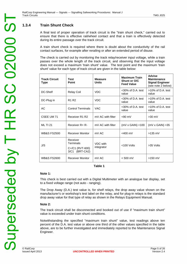
RailCorp Engineering Manual — Signals — Signalling Safeworking Procedures: Manual J Track Circuits TMG J025
© RailCorp Page 5 of 26 Issued April 2013 UNCONTROLLED WHEN PRINTED Version 2.4
1.3.4 Train Shunt Check
A final test of proper operation of track circuit is the "train shunt check," carried out to ensure that there is effective rail/wheel contact and that a train is effectively detected during its entire passage over the track circuit.
A train shunt check is required where there is doubt about the conductivity of the rail contact surfaces, for example after rerailing or after an extended period of disuse.
The check is carried out by monitoring the track relay/receiver input voltage, while a train passes over the whole length of the track circuit, and observing that the input voltage does not exceed a maximum 'train shunt' value. The test point and the maximum 'train shunt' value for each type of track circuit are given in the table below:
Track Circuit Type
Test Point
Measure Units
Maximum Train Shunt or O/C Feed Value
Advise Maintenance Signal Engineer (see note 2 below)
DC-Shelf Relay Coil VDC <30% of D.A. test value
>10% of D.A. test value
DC-Plug in R1 R2 VDC <30% of D.A. test value
>10% of D.A. test value
AC Control Terminals VAC <30% of D.A. test value
>10% of D.A. test value
CSEE UM 71 Receiver R1 R2 mV AC with filter <90 mV >30 mV
ML TI 21 Receiver R+ R- mV AC with filter (mV x GAIN) <100 (mV x GAIN) >35
WB&S FS2500 Receiver Monitor mV AC <400 mV >135 mV
Receiver Terminals
J/S C+/C1 (RVT-600) 3/C1 (BRT-CA2)
VDC with integrator <100 Volts >35 Volts
WB&S FS2600 Receiver Monitor mV AC < 500 mV >150 mV
Table 1
Note 1:
This check is best carried out with a Digital Multimeter with an analogue bar display, set to a fixed voltage range (not auto - ranging).
The Drop Away (D.A.) test value is, for shelf relays, the drop away value shown on the manufacturer's or workshop's test label on the relay, and for plug-in relays is the standard drop away value for that type of relay as shown in the Relays Equipment Manual.
Note 2:
The track circuit shall be disconnected and booked out of use if "maximum train shunt" value is exceeded under train shunt conditions.
Notwithstanding the specified "maximum train shunt" value, test readings above ten percent of the D.A. test value or above one third of the other values specified in the table above, are to be further investigated and immediately reported to the Maintenance Signal Engineer.
Sup
erse
ded
by T
HR
SC
020
00 S
T
RailCorp Engineering Manual — Signals — Signalling Safeworking Procedures: Manual J Track Circuits TMG J025
© RailCorp Page 6 of 26 Issued April 2013 UNCONTROLLED WHEN PRINTED Version 2.4
1.4 Polarity Test
Rail voltage polarities shall be checked using a voltmeter (and pulse integrator where applicable) to ensure that there is polarity reversal across all insulated rail joints between adjacent track circuits of the same type, namely 50Hz AC to 50Hz AC, DC to DC, Impulse to Impulse.
The existence of like polarities on these track circuits is acceptable only at a track feed to track feed interface, or with cut tracks where the track relay directly cuts the adjacent feed.
Polarity reversal does not apply to audio frequency track circuits.
The Maintenance Signal Engineer shall be advised of incorrect polarities between track circuits as soon as possible. The condition of the insulated rail joints shall be checked to ensure they are not liable to breakdown before the situation is corrected to the instructions of a Signal Engineer.
The Maintenance Signal Engineer shall consult with the Principal Engineer Signal Design, as necessary, to determine design solutions.
1.5 Track Circuit Adjustment
On installation, adjust track circuits and complete all entries shown on the track circuit history card.
a) Adjust track circuits with the track bonding (rail bonds, series bonds, parallelbonds, impedance bond side leads) and rail connections in good condition withlow resistance.
i) Track circuit feed voltages shall not be increased to compensate for opencircuit or high resistance bonding - in electrified areas high track feedvoltages could increase the probability of circulating currents throughtraction tie in bonding or earth’s.
b) Adjust and drop away shunt test track circuits preferably in dry ballastconditions. Track circuits adjusted in wet or poor ballast conditions shall bedrop away shunt tested again when the track has dried out, or the ballastconditions improved, to ensure correct shunting.
i) The Signalling Maintainer is to keep informed of planned works oractivities which could change track or ballast conditions and affect theproper adjustment of the track circuit and its ability to operate reliably andsafely.
ii) Minor adjustments should be carried out first and the Maintenance SignalEngineer is to be promptly informed.
iii) Should large adjustment or adjustment for unaccountable reason berequired, the Maintenance Signal Engineer shall be immediatelycontacted for instructions.
Whenever the track circuit is readjusted, measure and record all track circuit voltage readings on the track history card; carry out a fixed shunt test at all extremities and observe the relay pick up and drop away correctly. Also carry out a drop away shunt test at the relay/receiver end; if the variable shunt box is not on hand the drop away shunt test shall be performed as soon as practical.
Sup
erse
ded
by T
HR
SC
020
00 S
T

RailCorp Engineering Manual — Signals — Signalling Safeworking Procedures: Manual J Track Circuits TMG J025
© RailCorp Page 7 of 26 Issued April 2013 UNCONTROLLED WHEN PRINTED Version 2.4
In exceptional circumstances, if it is necessary to temporarily readjust a track circuit to compensate excessively wet or poor ballast conditions, an entry to that effect shall be made on the track circuit history card.
The Maintenance Signal Engineer shall be promptly advised and shall suitably record such advice. The suitably accredited Signalling Maintainer must regularly monitor the track circuit and the track must be readjusted immediately the ballast conditions have improved, the Maintenance Signal Engineer shall ensure the timely correction of the adjustment.
1.6 Interference/Repairs to Track Circuit Wires
Whenever two or more track circuit wires are disconnected and reconnected or repairs are made to two or more broken wires to or from track circuit equipment, ensure that the track relay has picked up and carry out a fixed shunt check or train shunt check to ensure that it drops away correctly. Where applicable, carry out a polarity reversal test between the affected track circuit and adjacent track circuits if there is any possibility of the track circuit polarity being altered.
1.7 Precautions associated with Contaminated (Rusty) Rails
Signalling Safeworking Procedure TMG J007 Apparatus Seldom Used shall be referenced for matters relating to the management of contaminated (rusty) rail caused by track circuits seldom used.
Signalling Safeworking Procedure TMG J026 Rerailing – Precautions to be Taken shall be referenced for matters relating to the certification of track circuits following rerailing.
1.8 Excessive sanding of the Track by Locomotives
When excessive sanding of tracks occurs in track circuited areas the effective shunting of track circuits could be affected.
Any case of excessive sanding is to be immediately brought to the attention of the Maintenance Signal Engineer, and also to the attention of the driver and/or nearest Signaller. The Network Control staff are to be requested to issue a NIN (NGE 214) Network Incident Notice to report the instance of excessive sanding.
Any instances of trains failing to shunt track circuits, intermittently or otherwise due to sand on the rail head, are to be immediately reported to the Maintenance Signal Engineer and fully investigated.
1.9 Precaution to be taken when inserting track circuit receivers
It is critical that CSEE receivers, especially, be plugged into their correct rack positions. The misallocation of a receiver by one module space can have unsafe consequences, with the permanent energisation of the track relay.
To prevent the occurrence of similar irregularities staff shall check that on all racking used for CSEE and Jeumont-Schneider track circuit equipment, every vacant module position above or below a unit of installed equipment is fitted with all obturation fittings and coding plugs.
Sup
erse
ded
by T
HR
SC
020
00 S
T

RailCorp Engineering Manual — Signals — Signalling Safeworking Procedures: Manual J Track Circuits TMG J025
© RailCorp Page 8 of 26 Issued April 2013 UNCONTROLLED WHEN PRINTED Version 2.4
2 Track Circuit Cyclic Maintenance 2.1 One Monthly Check of Double Rail 50Hz track circuits in
electrified areas.
Test 50Hz AC double rail track circuits in electrified areas on a monthly basis as follows, and record the results on the monthly check card:
a) track relay coil voltage, unoccupied
b) current in each rail, relay end, for balance
c) current in each rail, feed end, for balance
d) current in each cable of impedance bond side lead, up rail, for balance
e) current in each cable of impedance bond side lead, down rail, for balance
f) voltage drop across side lead connection to the up rail
g) voltage drop across side lead connection to the down rail
The track relay coil voltage should be roughly one volt under normal unoccupied conditions.
The current in each rail at the one location should be equal or within 0.5 amp as measured on an induction meter.
Investigate unbalance (unequal) current readings and advise the Maintenance Signal Engineer without delay.
The currents measured in each cable of a side lead pair of cables should be equal, or within 10%. Uneven current sharing indicates a high resistance side lead or connection.
The voltage drop across a side lead connection to the rail should be less than 10 millivolts AC.
Investigate changes in values significantly different to previous readings.
2.2 Regular Check of Parallel Bonds
Parallel bonds on track circuits extending over points to a clearance point on another line, shall be inspected on each occasion the set of points or the track circuit is maintained and whenever suitably accredited Signalling Maintainers are working in the vicinity of the points.
Where the track relay is connected such that open circuit or high resistance parallel bonds would fail the track circuit, then the inspections need only be carried out on the normal rostered maintenance visit to the track circuit.
To deter theft of copper traction bonds used for parallel bonding, maintenance staff should consider converting vulnerable bonds to aluminium or encase them in concrete filled surface conduits.
Staff must be vigilant when visiting locations where parallel bonding is provided to ensure bonding has not been damaged/removed by track machines, vandals or copper thieves.
Sup
erse
ded
by T
HR
SC
020
00 S
T

RailCorp Engineering Manual — Signals — Signalling Safeworking Procedures: Manual J Track Circuits TMG J025
© RailCorp Page 9 of 26 Issued April 2013 UNCONTROLLED WHEN PRINTED Version 2.4
2.3 Rostered Maintenance Visits
Specific attention and visual inspection shall be given, and necessary action taken on the following items:
a) Connections to the rails and the condition of cables for:
i) track circuit leads ( this shall include testing to ensure that the voltage drop across all Audio Frequency track lead connections to rail head to be of low resistance)
ii) series and parallel bonds
iii) mechanical fishplate bonds
iv) electrolysis bonds
v) impedance bond side leads
vi) traction tie-in leads
vii) emergency jumper bonds
The voltage drop across impedance bond side lead connections to the bond and to the rail shall be checked to be low resistance, ie; less than 10 millivolts AC.
b) Connections to air-cored inductors, tuning units, compensating capacitors and their connections.
c) Cable fasteners to rails and sleepers (including clip/cleating arrangements on concrete sleepers).
d) Insulated rail joints:
i) deterioration
ii) rail burning/burring over
iii) steel scale
iv) clear of ballast and metallic items
Note:
Use an induction meter to detect leakage through the insulated joints.
e) Where an insulated joint between track circuits is in need of repair, check for correct polarity reversal as a precautionary measure.
f) Point rodding, signal wires and debris such as spent drink cans or other metallic items coming into contact with rails and crossing noses.
g) Electric traction bonds or other cables being installed clear of, and insulated from, rails to which they are not bonded.
h) Rusty rails, sand or other contamination which could affect train shunts (on the contact surface of the rail).
Sup
erse
ded
by T
HR
SC
020
00 S
T

RailCorp Engineering Manual — Signals — Signalling Safeworking Procedures: Manual J Track Circuits TMG J025
© RailCorp Page 10 of 26 Issued April 2013 UNCONTROLLED WHEN PRINTED Version 2.4
i) Rail fasteners or Pandrol clips clear of fishplate bolts at insulated joints, and clipand chair insulation pads on concrete-sleepered track. Rail fasteners and railbonds clear of steel structure on bridges.
j) General condition of ballast.
k) Lightning protection equipment.
l) Relay track coil voltage on 50Hz AC DR track circuits 1 monthly (Passenger lines)
m) Record the voltage at the track receiver/relay and check against the lastrecorded value). 2 monthly
(Freight Only lines)
n) Relay track coil voltage on 50Hz AC SR track circuits 3 monthly
o) Relay track coil voltage on DC track circuits 3 monthly
p) Receiver Reference voltage on jointless and impulse type track circuits.3 monthly(6 monthly for ML type)
q) Rail current balance for 50Hz track circuits in electric traction areas,(double rail passenger - 1 monthly, double rail freight only - 2 monthly orsingle rail - 3 monthly).
r) Track relay pick up and drop away operation where practical, when the trackcircuit is shunted by a train.
s) On DC track circuits, battery condition, battery voltage, electrolyte level, and onprimary batteries the battery drain current. Record electrical readings andcompare with track circuit battery record card and battery life expectancy.
If the reading shows a variation from the last recorded value which is large enough that it cannot be accounted for by normal variations in ballast conditions, then further investigation and tests (see Section 2.6) shall be carried out. Severe degradation of performance of the track circuit outside normal behaviour or known symptoms of failure must be reported to the Maintenance Signal Engineer who shall arrange investigation.
In the case of double rail 50Hz AC track circuits, the current balance shall be determined by measuring the signalling current in both rails, at both the feed and relay ends of the track, using an Induction meter. This test is not highly accurate, due to variations induced by traction current harmonics; the test does give a convenient indication of unbalance in the rail currents, and any difference greater than 0.5 amps may be considered significant.
While there should not be stray 50Hz currents emanating from balanced double rail track circuits this is not the case with single rail 50Hz track circuits, where close tie in bonding between the traction rails of parallel tracks provides an alternate low resistance path for stray 50Hz track circuit currents. It may not then be unusual to measure unbalanced 50Hz currents in single rail track circuits.
Measuring rail current balance using a meter that is not 50Hz frequency selective may not be an accurate indicator because of traction harmonics flowing in the traction rail. Differences between the rail currents measured on an induction meter of greater than 1.25 amps on single rail 50Hz track circuits should be further investigated by checking other track circuits in the vicinity.
Sup
erse
ded
by T
HR
SC
020
00 S
T

RailCorp Engineering Manual — Signals — Signalling Safeworking Procedures: Manual J Track Circuits TMG J025
© RailCorp Page 11 of 26 Issued April 2013 UNCONTROLLED WHEN PRINTED Version 2.4
2.4 Maintenance of Traction Bonding
TMG J027 shall also be referenced for Traction Bonding.
Traction bonding includes parallel bonds between rails, tie-in bonds, cross bonds (rail to rail and rail to impedance bond), and traction bonds from rails to section hut or substation busbars.
Signalling Maintainers must ensure that traction bonding is in good condition, that open circuit bonds are immediately replaced, that high resistance connections are immediately rectified, and that deteriorated bonding is programmed for timely renewal.
Signalling Maintainers shall check the integrity of the traction bond during maintenance visits. Where traction bonds are visible throughout their entire length, an observation shall be sufficient to check their integrity. Where traction bonds are buried, the integrity shall be checked using a clamp meter on each parallel leg of the traction bond to ensure they are all carrying equal current. (Generally, series traction bonds to substations, etc, are buried, and parallel traction bonds are surface run).
The Maintenance Signal Engineer shall ensure that these bonding maintenance requirements are met.
2.4.1 Special Precautions Relating to AC Track Circuits
Where a fault condition causes AC track circuit currents to circulate via traction tie-in bonds or earths, etc through other track circuits (or where a fault condition causes AC currents in the DC traction supply) then a potentially unsafe condition can occur if a high resistance track circuit condition arises. All cases of open circuit or high resistance rail bonds, series bonds, impedance bond side leads, and their connections, shall be rectified promptly. Emergency jumper bonds, in good condition and correctly applied, should be utilised as required but replaced by permanent bonds as soon as possible. Any case where AC rail current unbalance is detected shall be immediately reported to the Signal Engineer, and the cause found and rectified without delay.
2.5 Annual and Two Yearly Maintenance Visits
2.5.1 Annual Inspection and Tests
In addition to the inspection and tests which are carried out on a normally rostered maintenance visit (see Section 2.3), the following impedance bond inspections and tests shall be carried out at intervals not exceeding 12 months.
a) Where impedance bonds, fitted with removable lids, are installed inside the track below top of sleeper level, then the lid shall be removed and the inside of the bond examined. Where these bonds are installed on the outside of the track on stands, or have fixed lids, then there is no requirement for periodic internal inspection.
The set screws securing the yoke to the laminated core and all terminal studs shall be kept tight. The windings shall be examined to ensure that the insulation is not displaced and that the coil leads are not fractured. The bond shall be examined to see that it is clean and dry and the case is not cracked. When replacing the lids of bonds installed in the four foot it is essential that the sealing of the connection inlets and hemp lid packing or gasket will effectively exclude the entry of water or other foreign matter. The set screws or bolts securing the lid shall be kept in good order and the wooden packing, where provided, maintained in position.
Sup
erse
ded
by T
HR
SC
020
00 S
T

RailCorp Engineering Manual — Signals — Signalling Safeworking Procedures: Manual J Track Circuits TMG J025
© RailCorp Page 12 of 26 Issued April 2013 UNCONTROLLED WHEN PRINTED Version 2.4
b) Jeumont Schneider CIT 1400 impedance bonds can suffer from loose back nutsso particular attention should be given to any loose terminations. Theconstruction of this bond brings out each half of the winding externally for tractionconnections. To prevent a possible cause for unbalanced traction return a goodsolid connection must be maintained between the two centre copper bars.Inspect this connection to ensure that the two bus bars form a good connection.
c) On MJS and ABW 1000 amps per rail impedance bonds the condition of theconnections is to be examined for looseness or any signs of oxidisation.
d) On 2000 Amps per rail impedance bonds there is an additional box mounted onthe rear of the bond containing either capacitors (2000R and 2000RAF) or atransformer (2000P). The lid on the box is to be removed and a check made forany loose or imperfect connections.
e) On resonated bonds the capacitor voltage is to be measured and recorded on therespective impedance bond capacitor history card. Variation in the voltagecompared to previous records is to be investigated.
Signalling Maintainers must also ensure that whenever a refurbished impedance bond is being installed, an internal inspection is carried out to ensure that it has suffered no damage or deterioration (e.g. damaged caused during storage or transport).
2.5.2 Two Yearly Inspection and Tests
In addition to the above, the following inspections and tests shall be carried out at intervals not exceeding two years.
a) Measure all voltage readings indicated on track circuit history cards according tothe methods prescribed for the type of track circuit under test and fill the resultsout on a new line on the card and compare with previous results.
b) Carry out a fixed shunt test, with the appropriate resistance value for the type oftrack circuit concerned (see Table 2), at all extremities of the track circuitincluding in points turnouts and crossovers and especially where connected byparallel bonding. Record details on the history card.
If the track fails to shunt at the minimum drop shunt value specified for that typeof track circuit, then a drop away shunt test shall be conducted and the SignalEngineer shall be informed immediately. The track circuit shall not be leftoperating in an unsafe condition.
c) In the case of compensated track circuits, record the rail-rail voltage at eachcapacitor connection for comparison with previous results.
d) Remove the track feed fuse and observe the track relay de-energise properly andcheck the track relay/receiver input voltage measures near zero and does notexceed the maximum O/C Feed values specified in the Table 1.
Notwithstanding the specified maximum "O/C Feed" value, test readings aboveten percent of the D.A. test value or above one third of the other values specifiedin the Table 1 are to be further investigated and immediately reported to theMaintenance Signal Engineer.
On DC track circuits, open circuiting of the track feed is important in determiningwhether there is any galvanic action (battery effect) between the rails or residualmagnetism in the relay. All cases where a DC track relay does not de-energisenormally with the track feed disconnected shall be promptly reported to theMaintenance Signal Engineer.
On AC vane relays supply to the local coil will also need to be opened.
Sup
erse
ded
by T
HR
SC
020
00 S
T
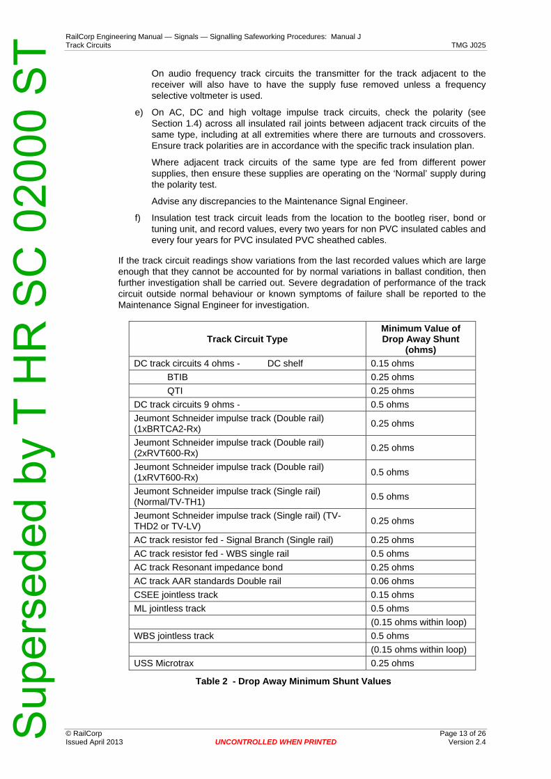
RailCorp Engineering Manual — Signals — Signalling Safeworking Procedures: Manual J Track Circuits TMG J025
© RailCorp Page 13 of 26 Issued April 2013 UNCONTROLLED WHEN PRINTED Version 2.4
On audio frequency track circuits the transmitter for the track adjacent to the receiver will also have to have the supply fuse removed unless a frequency selective voltmeter is used.
e) On AC, DC and high voltage impulse track circuits, check the polarity (see Section 1.4) across all insulated rail joints between adjacent track circuits of the same type, including at all extremities where there are turnouts and crossovers. Ensure track polarities are in accordance with the specific track insulation plan.
Where adjacent track circuits of the same type are fed from different power supplies, then ensure these supplies are operating on the ‘Normal’ supply during the polarity test.
Advise any discrepancies to the Maintenance Signal Engineer.
f) Insulation test track circuit leads from the location to the bootleg riser, bond or tuning unit, and record values, every two years for non PVC insulated cables and every four years for PVC insulated PVC sheathed cables.
If the track circuit readings show variations from the last recorded values which are large enough that they cannot be accounted for by normal variations in ballast condition, then further investigation shall be carried out. Severe degradation of performance of the track circuit outside normal behaviour or known symptoms of failure shall be reported to the Maintenance Signal Engineer for investigation.
Track Circuit Type Minimum Value of Drop Away Shunt
(ohms) DC track circuits 4 ohms - DC shelf 0.15 ohms BTIB 0.25 ohms QTI 0.25 ohms DC track circuits 9 ohms - 0.5 ohms Jeumont Schneider impulse track (Double rail) (1xBRTCA2-Rx) 0.25 ohms
Jeumont Schneider impulse track (Double rail) (2xRVT600-Rx) 0.25 ohms
Jeumont Schneider impulse track (Double rail) (1xRVT600-Rx) 0.5 ohms
Jeumont Schneider impulse track (Single rail) (Normal/TV-TH1) 0.5 ohms
Jeumont Schneider impulse track (Single rail) (TV-THD2 or TV-LV) 0.25 ohms
AC track resistor fed - Signal Branch (Single rail) 0.25 ohms AC track resistor fed - WBS single rail 0.5 ohms AC track Resonant impedance bond 0.25 ohms AC track AAR standards Double rail 0.06 ohms CSEE jointless track 0.15 ohms ML jointless track 0.5 ohms (0.15 ohms within loop) WBS jointless track 0.5 ohms (0.15 ohms within loop) USS Microtrax 0.25 ohms
Table 2 - Drop Away Minimum Shunt Values
Sup
erse
ded
by T
HR
SC
020
00 S
T

RailCorp Engineering Manual — Signals — Signalling Safeworking Procedures: Manual J Track Circuits TMG J025
© RailCorp Page 14 of 26 Issued April 2013 UNCONTROLLED WHEN PRINTED Version 2.4
2.6 Other Circumstances Requiring Testing
The inspections and tests required on maintenance visits shall also be carried out whenever there are changes which could affect the adjustment or polarity of the track circuits, including:
a) When the track circuit is newly installed.
b) In the case of 50Hz AC track circuits and DC track circuits with shelf relays,when a relay change has been carried out. Carry out a fixed shunt check at therelay and measure the relay voltage before and during the fixed shunt check.Compare the values with previous values, the track relay workshop test values,and the normally required values. Assess the need for readjustment.
c) After any of the following equipment items forming part of the track circuit hasbeen changed, eg: transformer, resistor, impedance bond, capacitor,transmitter, receiver, tuning unit, matching unit, shielding unit. Carry out a DropAway Shunt test at the relay/receiver-end to determine the value of shuntresistance required to shunt the track circuit. Also carry out a Fixed ShuntCheck at the relay/receiver-end and measure the relay/receiver voltage beforeand during the fixed shunt check. Compare the values with the previous values,the track relay workshop test values and the normally expected values. Assessthe need for readjustment.
d) After track work such as relaying or ballast cleaning which can affect theadjustment of the track circuit. Carry out a fixed shunt check at the relay endand measure the relay/receiver voltage before and during the fixed shunt check.Compare the values with the previous values, the track relay workshop testvalues and the normally required values. Assess the need for readjustment.
e) When track circuit readjustment is required proceed as stipulated in Section 1.5.When a track circuit is readjusted a drop away shunt test is also required aswell as a fixed shunt test at all extremities.
f) As required, when investigating No Cause Found failures, etc.
g) Whenever both track circuit feed wires and relay wires are disconnected andreconnected, carry out polarity tests between adjacent track circuits requiringpolarity reversal.
Whenever track circuit feed wires or relay wires have been reconnected, or a50Hz track feed transformer has been changed, the track relay must beobserved to pick up correctly to ensure that there has been no change to thecircuit polarity.
Whenever the polarity of power supply transformers or wiring feeding the trackcircuits is subject to change, carry out polarity tests between adjacent trackcircuits requiring polarity reversal which are fed from different power supplies.
h) When a mishap has occurred in which the signalling arrangements are beingquestioned, under the direction of the investigating Signal Engineer.
Sup
erse
ded
by T
HR
SC
020
00 S
T

RailCorp Engineering Manual — Signals — Signalling Safeworking Procedures: Manual J Track Circuits TMG J025
© RailCorp Page 15 of 26 Issued April 2013 UNCONTROLLED WHEN PRINTED Version 2.4
50Hz A.C. TRACK CIRCUIT TRACK CIRCUIT HISTORY CARD LENGTH m DOUBLE RAIL TRACK
NUMBER OF IMPEDANCE BONDS SINGLE RAIL
IMPEDANCE BOND TYPE TRACK FEED TYPE ∗ RELAY TYPE ∗ TEST SHUNT ∗ CHANGE OF RELAYS STORE 37 (100VA)
VT1 WBS S.R. 0.5Ω DATE
SERIAL No
P.U. VOLTS
COMP.VOLTS
D.A. VOLTS
STORE 45 (200VA)
G.R.S SIG.BCH S.R. 0.25Ω
STORE 47 (200VA)
KYOSAN D.R. (RESONATED BOND) 0.25Ω
W.B.S. (220VA) McK&H / WBS
D.R. (STANDARD BOND) 0.06Ω
Where applicable ∗ PLACE CROSS AGAINST APPROVED TYPE
FEED END RELAY END CHECKS DATE Mains
Supply Voltage
Secondary
Voltage
Current
Track (2) Voltage
(V)
Rail Current (1)
(A)
Track (2) Voltage
(V)
Relay Volts (V)
Zero Feed (mV)
Drop Shunt
Phase Check
Test Shunt
Bonds / Rail Connections
Ballast Conditions
Signature of Testing
Officer (V) (V) (A) UP DN UP DN UP DN Cont Local Cont Local (Ω) (OK) Ω (Y / N)
(1) CHECK RAIL CURRENTS ARE WITHIN 0.5A (2) RECORD VOLTAGE EACH RAIL TO NEUTRAL ON DOUBLE RAIL ELECTRIFIED TRACKS
Sup
erse
ded
by T
HR
SC
020
00 S
T
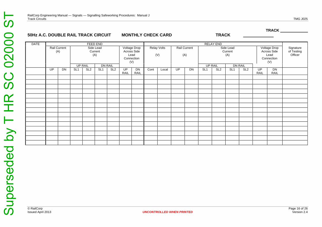
RailCorp Engineering Manual — Signals — Signalling Safeworking Procedures: Manual J Track Circuits TMG J025
© RailCorp Page 16 of 26 Issued April 2013 UNCONTROLLED WHEN PRINTED Version 2.4
TRACK 50Hz A.C. DOUBLE RAIL TRACK CIRCUIT MONTHLY CHECK CARD TRACK
DATE FEED END RELAY END Rail Current
(A) Side Lead
Current (A)
Voltage DropAcross Side
Lead Connection
(V)
Relay Volts
(V)
Rail Current
(A)
Side Lead Current
(A)
Voltage Drop Across Side
Lead Connection
(V)
Signature of Testing
Officer
UP RAIL DN RAIL UP RAIL DN RAIL UP DN SL1 SL2 SL1 SL2 UP
RAIL DN
RAIL Cont Local UP DN SL1 SL2 SL1 SL2 UP
RAIL DN
RAIL
Sup
erse
ded
by T
HR
SC
020
00 S
T

RailCorp Engineering Manual — Signals — Signalling Safeworking Procedures: Manual J Track Circuits TMG J025
© RailCorp Page 17 of 26 Issued April 2013 UNCONTROLLED WHEN PRINTED Version 2.4
DC TRACK CIRCUITS TRACK CIRCUIT HISTORY CARD LENGTH m TRACK POS. RAIL (UP / DN)
FEED END RELAY END Date (√)
New Battery
Mains Supply
DC Supply
Feed Resistance
Volts on Track Terminals
Volts on Track Terminals (V)
Polarity Drop Shunt
Fixed Shunt Test
Ballast Condition
Signature of
Testing Officer (V) (V) (Ω) Unoc-
cupied With
Shunt On
Zero Feed
(OK) (Ω) (Ω
)
TRACK FEED TYPE PRIMARY BATTERY CHRGR.+ SEC.BATT.
RELAY TYPE DC SHELF 4Ω
TEST SHUNT 0.15Ω
SOLAR STR.70 + PR.BATT.
BT 1B 4Ω QT1 4Ω
0.25Ω 0.25Ω
STORE 72 TR 17
QTM1 4Ω QT1 9Ω
0.25Ω 0.5Ω
DC (AC IMMUNE) QTA1 9Ω 0.5Ω Place X against appropriate type
Sup
erse
ded
by T
HR
SC
020
00 S
T

RailCorp Engineering Manual — Signals — Signalling Safeworking Procedures: Manual J Track Circuits TMG J025
© RailCorp Page 18 of 26 Issued April 2013 UNCONTROLLED WHEN PRINTED Version 2.4
CSEE TYPE UM71 TRACK CIRCUITS TRACK CIRCUIT HISTORY CARD LENGTH m TRACK FREQUENCY Hz
TRANSMITTER END RECEIVER END ∗
DATE Tx Tx TU or MU DC Rx Rx TU Rx VR1 / R2 PSU DC Drop 0.15Ω Ballast Signature Serial
No Input to
MU (E1/E2)
(V)
V1/V2
(V)
Volts A+/ A-
(V)
Serial No
V1/V2
(V)
Input (9/10 on
MU) (V)
Unoc-cupied(mV)
With shunt
on (mV)
Zero Feed (mV)
KRV Serial No
Volts A+/ A-
(V)
Shunt
(Ω)
Shunt Test
Condition of Testing Officer
∗ Measure with Selective Meter or with Adjacent Tx Disconnected
Sup
erse
ded
by T
HR
SC
020
00 S
T

RailCorp Engineering Manual — Signals — Signalling Safeworking Procedures: Manual J Track Circuits TMG J025
© RailCorp Page 19 of 26 Issued April 2013 UNCONTROLLED WHEN PRINTED Version 2.4
Rx CONNECTIONS TYPE T1 Tx CONNECTIONS TYPE T1
A -L -T
C 2 V 3
A + L + C C 1 V 1
M
R 6 R 7 R 8 R 9
R 1 0
R 1 R 2R 3 R 4 R 5
V 2
A -
M 4 M 5
A +
M 1 M 2 M 3
M
V 6 V 7 V 8 V 9
V 1 0
V 2 V 1
V 3 V 4 V 5
FREQ KEM CONNECT BRIDGE Hz 1 on Mu to 2 on Mu to
1700 3,5 V2 V7 V3 - V4 V5 - V6
2300 4 V7 V8 2000 3,75 V1 V7 V3 - V4 V5 -
V6 2600 4,25 V1 V8 V2 - V7
Sup
erse
ded
by T
HR
SC
020
00 S
T
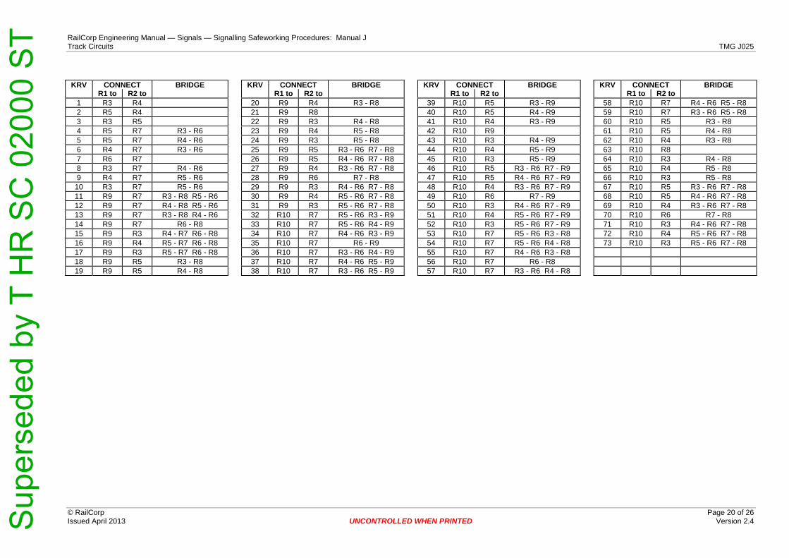
RailCorp Engineering Manual — Signals — Signalling Safeworking Procedures: Manual J Track Circuits TMG J025
© RailCorp Page 20 of 26 Issued April 2013 UNCONTROLLED WHEN PRINTED Version 2.4
KRV CONNECT BRIDGE KRV CONNECT BRIDGE KRV CONNECT BRIDGE KRV CONNECT BRIDGE
R1 to R2 to R1 to R2 to R1 to R2 to R1 to R2 to 1 R3 R4 20 R9 R4 R3 - R8 39 R10 R5 R3 - R9 58 R10 R7 R4 - R6 R5 - R8 2 R5 R4 21 R9 R8 40 R10 R5 R4 - R9 59 R10 R7 R3 - R6 R5 - R8 3 R3 R5 22 R9 R3 R4 - R8 41 R10 R4 R3 - R9 60 R10 R5 R3 - R8 4 R5 R7 R3 - R6 23 R9 R4 R5 - R8 42 R10 R9 61 R10 R5 R4 - R8 5 R5 R7 R4 - R6 24 R9 R3 R5 - R8 43 R10 R3 R4 - R9 62 R10 R4 R3 - R8 6 R4 R7 R3 - R6 25 R9 R5 R3 - R6 R7 - R8 44 R10 R4 R5 - R9 63 R10 R8 7 R6 R7 26 R9 R5 R4 - R6 R7 - R8 45 R10 R3 R5 - R9 64 R10 R3 R4 - R8 8 R3 R7 R4 - R6 27 R9 R4 R3 - R6 R7 - R8 46 R10 R5 R3 - R6 R7 - R9 65 R10 R4 R5 - R8 9 R4 R7 R5 - R6 28 R9 R6 R7 - R8 47 R10 R5 R4 - R6 R7 - R9 66 R10 R3 R5 - R8
10 R3 R7 R5 - R6 29 R9 R3 R4 - R6 R7 - R8 48 R10 R4 R3 - R6 R7 - R9 67 R10 R5 R3 - R6 R7 - R8 11 R9 R7 R3 - R8 R5 - R6 30 R9 R4 R5 - R6 R7 - R8 49 R10 R6 R7 - R9 68 R10 R5 R4 - R6 R7 - R8 12 R9 R7 R4 - R8 R5 - R6 31 R9 R3 R5 - R6 R7 - R8 50 R10 R3 R4 - R6 R7 - R9 69 R10 R4 R3 - R6 R7 - R8 13 R9 R7 R3 - R8 R4 - R6 32 R10 R7 R5 - R6 R3 - R9 51 R10 R4 R5 - R6 R7 - R9 70 R10 R6 R7 - R8 14 R9 R7 R6 - R8 33 R10 R7 R5 - R6 R4 - R9 52 R10 R3 R5 - R6 R7 - R9 71 R10 R3 R4 - R6 R7 - R8 15 R9 R3 R4 - R7 R6 - R8 34 R10 R7 R4 - R6 R3 - R9 53 R10 R7 R5 - R6 R3 - R8 72 R10 R4 R5 - R6 R7 - R8 16 R9 R4 R5 - R7 R6 - R8 35 R10 R7 R6 - R9 54 R10 R7 R5 - R6 R4 - R8 73 R10 R3 R5 - R6 R7 - R8 17 R9 R3 R5 - R7 R6 - R8 36 R10 R7 R3 - R6 R4 - R9 55 R10 R7 R4 - R6 R3 - R8 18 R9 R5 R3 - R8 37 R10 R7 R4 - R6 R5 - R9 56 R10 R7 R6 - R8 19 R9 R5 R4 - R8 38 R10 R7 R3 - R6 R5 - R9 57 R10 R7 R3 - R6 R4 - R8
Sup
erse
ded
by T
HR
SC
020
00 S
T
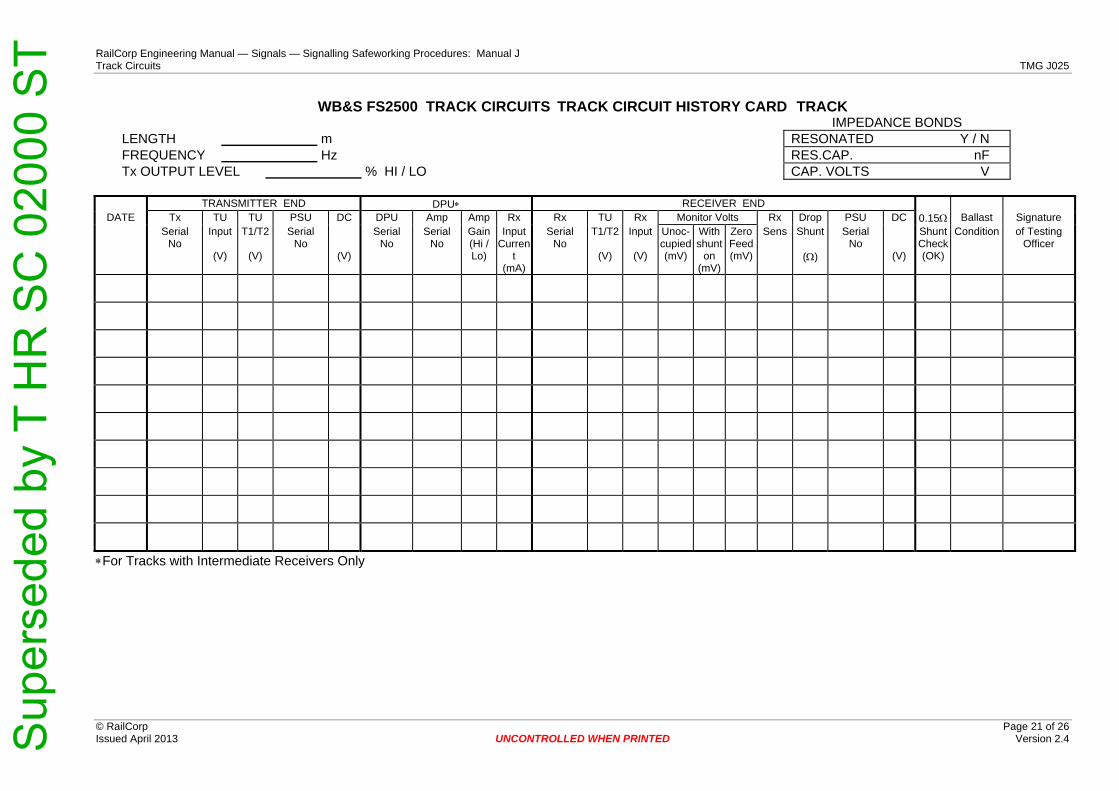
RailCorp Engineering Manual — Signals — Signalling Safeworking Procedures: Manual J Track Circuits TMG J025
© RailCorp Page 21 of 26 Issued April 2013 UNCONTROLLED WHEN PRINTED Version 2.4
WB&S FS2500 TRACK CIRCUITS TRACK CIRCUIT HISTORY CARD TRACK IMPEDANCE BONDS
LENGTH m RESONATED Y / N FREQUENCY Hz RES.CAP. nF Tx OUTPUT LEVEL % HI / LO CAP. VOLTS V
TRANSMITTER END DPU∗ RECEIVER END DATE Tx TU TU PSU DC DPU Amp Amp Rx Rx TU Rx Monitor Volts Rx Drop PSU DC 0.15Ω Ballast Signature
Serial No
Input
(V)
T1/T2
(V)
Serial No
(V)
SerialNo
SerialNo
Gain (Hi / Lo)
InputCurren
t (mA)
Serial No
T1/T2
(V)
Input
(V)
Unoc-cupied(mV)
With shunt
on (mV)
Zero Feed(mV)
Sens Shunt
(Ω)
Serial No
(V)
Shunt Check(OK)
Condition of Testing Officer
∗For Tracks with Intermediate Receivers Only
Sup
erse
ded
by T
HR
SC
020
00 S
T

RailCorp Engineering Manual — Signals — Signalling Safeworking Procedures: Manual J Track Circuits TMG J025
© RailCorp Page 22 of 26 Issued April 2013 UNCONTROLLED WHEN PRINTED Version 2.4
RECEIVER SENSITIVITY ADJUSTMENT TABLE GUIDE TO Tx OUTPUT LEVEL ADJUSTMENT
SENS CONNECT BRIDGE Nominal Track Circuit Length
Tx Output Level
Output Number
Terminals ∗ Used
A to B to 50 - 250 m 20% 1 (LO) 1 and 2 1.65 -45 +5 +45 to -15 +15 to -5 250 - 450 m 40% 2 1 and 3 1.60 -45 +15 +45 to -15 450 - 600 m 60% 3 3 and 4 1.55 -45 -5 +45 to -15 +15 to +5 600 - 750 m 80% 4 2 and 4 1.50 -45 +5 +45 to -5 750 - 900 m 100% 5 (HI) 1 and 4 1.45 -45 +451.40 -45 -5 +45 to +5 ∗The Screen Terminal is Earthed 1.35 -45 +5 +45 to +15 -15 to -5 1.30 -45 -15 +45 to +15 1.25 -45 -5 +45 to +15 -15 to +5 1.20 -15 +5 +15 to -5 1.15 -15 +151.10 -15 -5 +15 to +5 1.05 -5 +51.00 B0.95 +5 -50.90 +15 +5 -15 to -5 0.85 +15 -150.80 +15 -5 -15 to +5 0.75 +45 +5 -45 to -15 +15 to -5 0.70 +45 +15 -45 to -15 0.65 +45 -5 -45 to -15 +15 to +5 0.60 +45 +5 -45 to -5 0.55 +45 -450.50 +45 -5 -45 to +5 0.45 +45 +5 -45 to +15 -15 to -5 0.40 +45 -15 -45 to +15 0.35 +45 -5 -45 to +15 -15 to +5
Sup
erse
ded
by T
HR
SC
020
00 S
T
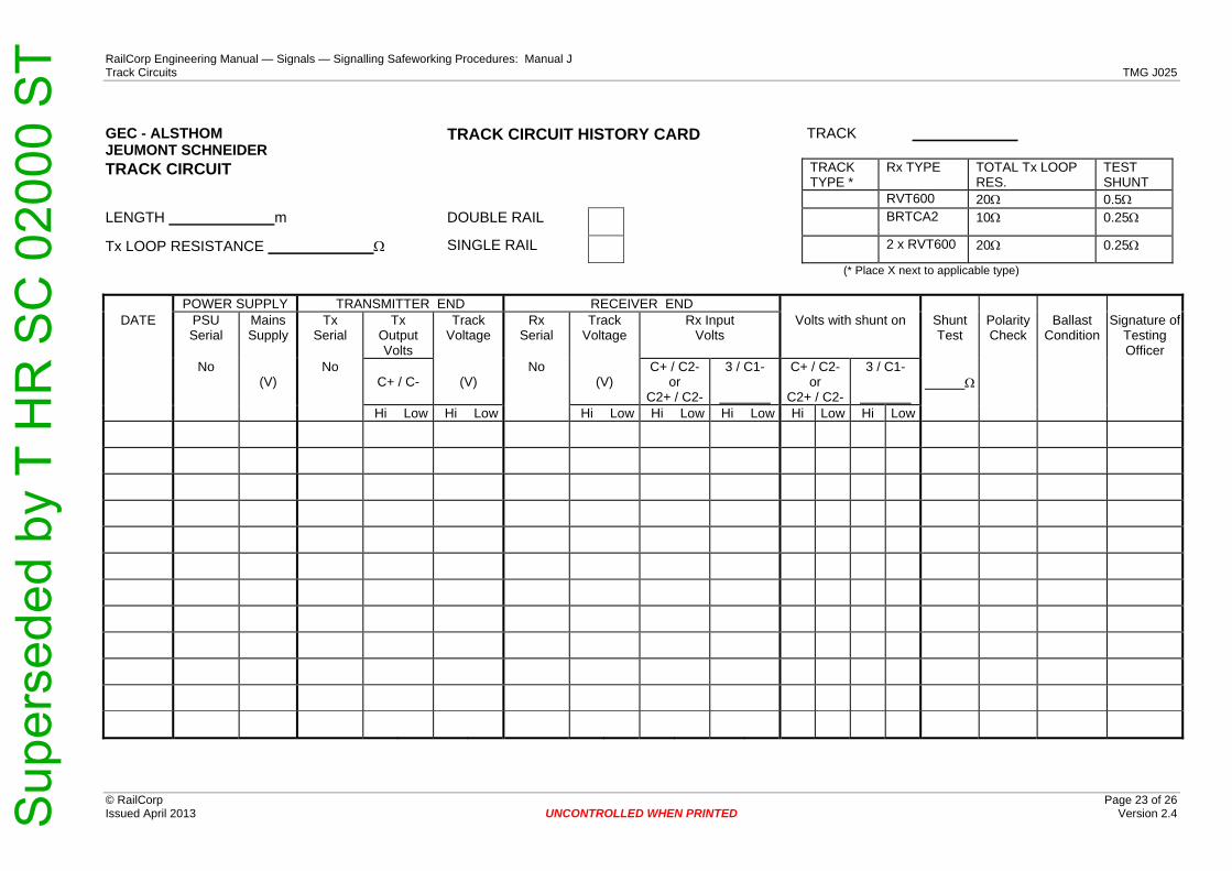
RailCorp Engineering Manual — Signals — Signalling Safeworking Procedures: Manual J Track Circuits TMG J025
© RailCorp Page 23 of 26 Issued April 2013 UNCONTROLLED WHEN PRINTED Version 2.4
GEC - ALSTHOM JEUMONT SCHNEIDER
TRACK CIRCUIT HISTORY CARD TRACK
TRACK CIRCUIT TRACK TYPE *
Rx TYPE TOTAL Tx LOOP RES.
TEST SHUNT
RVT600 20Ω 0.5Ω LENGTH m DOUBLE RAIL BRTCA2 10Ω 0.25Ω
Tx LOOP RESISTANCE Ω SINGLE RAIL 2 x RVT600 20Ω 0.25Ω
(* Place X next to applicable type)
POWER SUPPLY TRANSMITTER END RECEIVER END DATE PSU
Serial Mains Supply
Tx Serial
Tx Output Volts
Track Voltage
Rx Serial
Track Voltage
Rx Input Volts
Volts with shunt on Shunt Test
Polarity Check
Ballast Condition
Signature of Testing Officer
No (V)
NoC+ / C- (V)
No(V)
C+ / C2- or
C2+ / C2-
3 / C1- C+ / C2- or
C2+ / C2-
3 / C1- Ω
Hi Low Hi Low Hi Low Hi Low Hi Low Hi Low Hi Low
Sup
erse
ded
by T
HR
SC
020
00 S
T

RailCorp Engineering Manual — Signals — Signalling Safeworking Procedures: Manual J Track Circuits TMG J025
© RailCorp Page 24 of 26 Issued April 2013 UNCONTROLLED WHEN PRINTED Version 2.4
TYPE ABB - ML TI 21 TRACK CIRCUITS TRACK CIRCUIT HISTORY CARD
TRACK LENGTH m FREQUENCY Tu INPUT POWER (Hi / Low)
TRANSMITTER END RECEIVER END mV Across 1Ω
DATE Tx Serial
No
Tu Input (V)
Tu T1/T2
(V)
PSU Serial
No
DC Volts
(V)
Rx Serial
No
Tu T1/T2
(V)
Rx Input (V)
Unoc-cupied
(mV)
With shunt
on
(mV)
Zero Feed
(mV)
Gain Setting
Drop Shunt Value( Ω )
PSU Serial
No
DC Volts
(V)
0.15Ω Shunt Test
Ballast Condition
Signature of
Testing Officer
Sup
erse
ded
by T
HR
SC
020
00 S
T
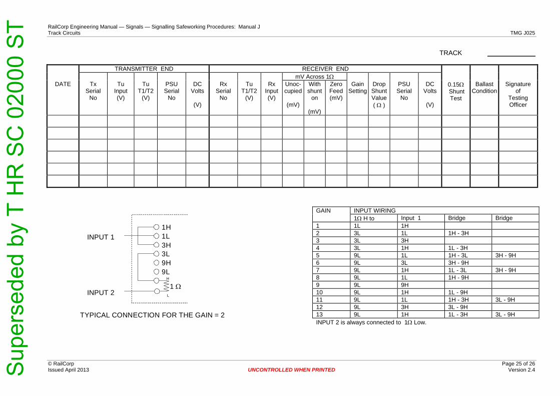
RailCorp Engineering Manual — Signals — Signalling Safeworking Procedures: Manual J Track Circuits TMG J025
© RailCorp Page 25 of 26 Issued April 2013 UNCONTROLLED WHEN PRINTED Version 2.4
TRACK
TRANSMITTER END RECEIVER END mV Across 1Ω
DATE Tx Serial
No
Tu Input (V)
Tu T1/T2
(V)
PSU Serial
No
DC Volts
(V)
Rx Serial
No
Tu T1/T2
(V)
Rx Input (V)
Unoc-cupied
(mV)
With shunt
on
(mV)
Zero Feed (mV)
Gain Setting
Drop Shunt Value( Ω )
PSU Serial
No
DC Volts
(V)
0.15Ω Shunt Test
Ballast Condition
Signature of
Testing Officer
GAIN INPUT WIRING 1Ω H to Input 1 Bridge Bridge 1 1L 1H 2 3L 1L 1H - 3H 3 3L 3H 4 3L 1H 1L - 3H 5 9L 1L 1H - 3L 3H - 9H 6 9L 3L 3H - 9H 7 9L 1H 1L - 3L 3H - 9H 8 9L 1L 1H - 9H 9 9L 9H 10 9L 1H 1L - 9H 11 9L 1L 1H - 3H 3L - 9H 12 9L 3H 3L - 9H 13 9L 1H 1L - 3H 3L - 9H INPUT 2 is always connected to 1Ω Low.
1H1L3H3L9H9L
1 ΩH
L
INPUT 1
INPUT 2
TYPICAL CONNECTION FOR THE GAIN = 2
Sup
erse
ded
by T
HR
SC
020
00 S
T
RailCorp Engineering Manual — Signals — Signalling Safeworking Procedures: Manual JTrack Circuits
© RailCorp Page 26 of 26 Issued April 2013 UNCONTROLLED WHEN PRINTED Version 2.4
This page has been intentionally left blank
Sup
erse
ded
by T
HR
SC
020
00 S
T

RailCorp Engineering Manual — Signals — Signalling Safeworking Procedures: Manual J Rerailing – Precautions to be Taken TMG J026
© RailCorp Page 1 of 10 Issued February 2011 UNCONTROLLED WHEN PRINTED Version 2.2
TMG J026 RERAILING – PRECAUTIONS TO BE
TAKEN Version 2.2
Issued February 2011
Document control
Version Date Summary of change Replaced SC 00 52 00 26 SI Rerailing – Precautions to be Taken.
1.1 30 July 2008 Clarify booking out and disconnection process in 1.2 1.2 May 2010 Application of TMA 400 format 2.0 July 2010 Rewrite of document to clearly describe rerailing precautions and
process. 2.1 October 2010 Removed provision for trainstop suppression in 3.1.1
Deleted duplicated paragraph 3.3.2 Added requirement for isolation of 1500V DC in 3.1.2
2.2 February 2011 Changed paragraph title - section 3.3 to "Newly Installed Rail"
Contents 1 Introduction .............................................................................................................................3 2 Authorisation and Attendance...............................................................................................3 3 Precautions..............................................................................................................................4
3.1 Prior to the Commencement of Rerailing ..................................................................4 3.1.1 Affected Apparatus.....................................................................................4 3.1.2 Electrified Areas .........................................................................................5
3.2 Reinstatement Process following Rerailing ...............................................................6 3.3 Newly Installed Rails.................................................................................................6
3.3.1 Exception to Train Shunt Check.................................................................7 3.3.1.1 Short Sections of New Rail (not exceeding 15 metres in
length) ........................................................................................................7 3.3.1.2 Long Sections of New Rail (exceeding 15 metres in length) .....................7
3.4 Rerailing Affecting Parallel Bonding ..........................................................................7 4 Guidelines for the use of Temporary Rail Bonds ................................................................8
4.1 Scope.........................................................................................................................8 4.2 Restriction for Double Rail Track Circuits..................................................................8 4.3 Applicable Circumstances .........................................................................................8 4.4 Applicable Procedures...............................................................................................8 4.5 Competence ..............................................................................................................8 4.6 Issuing Temporary Rail Bonds ..................................................................................9
Sup
erse
ded
by T
HR
SC
020
00 S
T
RailCorp Engineering Manual — Signals — Signalling Safeworking Procedures: Manual J Rerailing – Precautions to be Taken TMG J026
© RailCorp Page 2 of 10 Issued February 2011 UNCONTROLLED WHEN PRINTED Version 2.2
4.7 Application in Electrified areas ..................................................................................9 4.8 Application in Non Electrified areas...........................................................................9 4.9 Special Situations ......................................................................................................9
Sup
erse
ded
by T
HR
SC
020
00 S
T

RailCorp Engineering Manual — Signals — Signalling Safeworking Procedures: Manual J Rerailing – Precautions to be Taken TMG J026
© RailCorp Page 3 of 10 Issued February 2011 UNCONTROLLED WHEN PRINTED Version 2.2
1 Introduction When rerailing (or other trackwork which involves breaking the rail) occurs on track circuited or electrified areas, certain precautions shall be taken to ensure all the risks associated with the work are understood and controlled. Generally these precautions include the protection of trains, alternative arrangements for traction return and the testing and certification of affected track circuits and associated signalling before restoring the apparatus back into use.
This document outlines the general precautions that apply when rerailing and shall be read in conjunction with other chapters of the Signalling Safeworking Procedures including:
• TMG J002 Bridging or False Feeding of Signalling Circuits
• TMG J008 Booking Signalling Equipment Out of Use
• TMG J009 Disconnection of Signalling Apparatus
• TMG J025 Track Circuits
• TMG J027 Traction Return (1500V DC)
2 Authorisation and Attendance Planned rerailing work requiring a track possession is carried out in accordance with Network Rules & Procedures.
The Signalling Maintainer shall attend whenever there is replacement of rail in the following cases:
• Within interlocked areas, except in areas where outer home signals are provided and the intervening track circuits do not impact on the operation of the interlocking.
• At points, in any intermediate location outside an interlocking.
• In plain track areas, where the length of rerailing exceeds 6 metres.
• In single line electrified areas.
• In the vicinity of insulated joints, tuned loops or any other track interface, including short sections of rail in the vicinity of the clearance point between converging tracks.
• Outside sub-stations and sectioning huts.
• Wherever traction bonding cable or track circuit cabling could be interfered with.
When the Signalling Maintainer is in attendance, they shall disconnect the track circuit and the affected signalling, and if required provide an alternative path for the traction return current. Upon completion, the Signalling Maintainer shall reinstate and test the affected track circuit/s and ensure that the rail surfaces are clean before restoring the signalling back into use.
Sup
erse
ded
by T
HR
SC
020
00 S
T

RailCorp Engineering Manual — Signals — Signalling Safeworking Procedures: Manual J Rerailing – Precautions to be Taken TMG J026
© RailCorp Page 4 of 10 Issued February 2011 UNCONTROLLED WHEN PRINTED Version 2.2
Where it is not necessary for the Signalling Maintainer to attend trackwork (as described in section 4.3 of this procedure), Temporary Rail Bonds are authorised by a Signal Engineer for use by the Civil Discipline representative in accordance with these procedures. The Civil Discipline representative shall be properly instructed and qualified in the use of the Temporary Rail Bonds. Refer to section 4 of this procedure for more detail.
3 Precautions 3.1 Prior to the Commencement of Rerailing
3.1.1 Affected Apparatus
Prior to commencement of the rerailing, an Infrastructure Booking Authority (IBA) NRF 003 form shall be compiled in accordance with Signalling Safeworking Procedure TMG J008 and Network Rules & Procedures NWT 312 & NPR 704, showing the full particulars of the equipment affected and signed by the Civil and Signalling Discipline representatives. Where the Electrical Discipline is involved, the representative of that discipline shall also sign the form.
Where the rerailing affects the operation of signals and points controlled from a Signal Box, an entry shall also be made in the Train Register Book and the signed IBA form (or a transmitted/transcribed copy) shall be attached to the current page of that book.
The relevant signalling apparatus must not be disconnected until the IBA form has been duly signed by the Network Control Officer. Trackwork affecting the track circuit must not commence until authorised by the Signalling Maintainer in attendance, stating the relevant signalling apparatus has been disconnected and alternative traction arrangements (as required) have been implemented.
Disconnection of affected signalling and the placement of handsignallers shall be in accordance with Signalling Safeworking Procedure TMG J009 and the Network Rules & Procedures, particularly ensuring that:
• Handsignallers (where required) are positioned at their posts before the signals protecting the section where the rerailing is to take place are disconnected and maintained at stop.
• Where rerailing occurs on the overlap track circuits, the signal in the rear shall also be disconnected and maintained at stop.
• Trainstops provided at protecting signal/s affected by the rerailing work shall be maintained in the trip position.
• In areas where two-way operation occurs, the immediate protecting signal in each direction shall be booked out of use and disconnected in conjunction with the track relay of the particular track affected. Where signals other than the immediate protection signals are affected by the rerailing, and it is impractical to disconnect each signal, then it is sufficient to only book these signals out of use without the requirement to disconnect. Where Starting signals are not directly affected by the rerailing work, then these signals may be left operational.
When rerailing affects the operation of an automatic level crossing, the crossing shall be protected in accordance with Signalling Safeworking Procedure TMG J009 & Network Procedure NPR 715.
Sup
erse
ded
by T
HR
SC
020
00 S
T

RailCorp Engineering Manual — Signals — Signalling Safeworking Procedures: Manual J Rerailing – Precautions to be Taken TMG J026
© RailCorp Page 5 of 10 Issued February 2011 UNCONTROLLED WHEN PRINTED Version 2.2
Where the level crossing is situated in double line automatic areas, and is disconnected in accordance with TMG J009, the signals approaching the level crossing on the track not affected by the rerailing may be left working if required.
Where level crossing protection is disconnected as a result of rerailing, it shall be fully tested (by operation of the approach track circuits) before the level crossing protection is booked back into use.
3.1.2 Electrified Areas
In 1500V DC electrification areas, before any interference with the rails forming part of the traction return is permitted, adequate provision shall be made for a safe return path for the traction current to the sub-station or section hut. At the same time the signalling equipment shall be safeguarded against damage due to a possible rise in traction return voltage.
When rerailing past a section hut care shall be taken that one negative connection to the rail/impedance bonds is maintained at all times.
Where negative cable connections are to a single rail, rerailing shall be done in two stages, up to one side of the mechanical joint as a first stage, and when bonding of that portion is complete and the negative cable connection to the section hut is restored the remainder of the rerailing may be carried out as the second stage.
In the case of negative cable connections to impedance bonds, the rerailing should be carried out on one rail at a time, with the other rail fully bonded and its negative connection complete via the impedance bond.
In all cases where rerailing is to be carried out involving the 1500V DC negative rail connection at a sectioning hut or sub-station, the staff of the Discipline responsible for the work must notify the Electrical Operations Centre (EOC) of the work to be performed before rerailing commences.
In areas where the mechanical joint has been welded out, and there is only the one set of negative connections, the rails must first be cut so as both connections are not broken simultaneously. Where it is not possible for the rail to be cut, isolation of the 1500V DC traction must be initially obtained.
In all cases, where there are negative connections and the entire track is to be removed and replaced, isolation of the 1500V DC traction must be initially obtained.
Signalling Safeworking Procedure TMG J027 shall be referenced for additional information in relation to the precautions and safeguards which apply to traction return, particularly where there are multiple negative connections or when it is necessary to disconnect traction bonding and impedance bonds.
Sup
erse
ded
by T
HR
SC
020
00 S
T

RailCorp Engineering Manual — Signals — Signalling Safeworking Procedures: Manual J Rerailing – Precautions to be Taken TMG J026
© RailCorp Page 6 of 10 Issued February 2011 UNCONTROLLED WHEN PRINTED Version 2.2
3.2 Reinstatement Process following Rerailing
When the rerailing is complete, the Civil Discipline representative can sign-off their portion of the IBA form. The Signalling Maintainer (when in attendance) shall test the track circuit/s affected by rerailing in accordance with Signalling Safeworking Procedure TMG J025.
In particular, the following requirements shall be applied before the work can be certified and the signalling brought back into use:
• On AC & DC track circuits, ensure the track relay operates correctly and drops away freely when de-energised. Compare the values with the previous values, the track relay workshop test values and the normally required values. Assess the need for readjustment.
• On AC, DC & Jeumont Schneider track circuits, where track connections have been disturbed or insulated rail joints installed, testing shall be carried out to see that the tracks are of correct polarity.
• Carry out a Fixed Shunt Check at the relay end and measure the relay/receiver voltage before and during the Fixed Shunt Check.
• Carry out a Train Shunt Check to ensure satisfactory shunting of the rails by the train wheels.
If trainstops have been affected by the rerailing, they shall be regauged and any temporary bridging removed.
All affected signalling shall be observed to be operational prior to being available for use.
The IBA form can then be completed and signed by the Signalling Maintainer and the Network Control Officer. Handsignallers may then be withdrawn.
3.3 Newly Installed Rails
After rerailing, where rail surfaces are not clean and thus contaminated with rust or other foreign substances, the Signalling Maintainer shall conduct a Train Shunt Check to ensure that a train is effectively detected over the complete length of the track circuit.
Rail surfaces must be clean for sections of track even as short as 2 metres (the wheel base of a single bogie) when that section of track is located within 15 metres (a vehicle wheel base) of an insulated rail joint between adjacent track circuits.
When insulated rail joints are renewed, a dangerous situation could arise, for example: a rear bogie of a train could come to stand on the rusty portion of the new rail of an insulated rail joint which may be located just at the clearance point between two converging tracks and not be detected. Similarly, short sections of new rail within a tuned loop, if critically located in respect of a clearance point might also cause problems.
In these cases, the Signalling Maintainer shall request the Civil Discipline representative to grind the surface of the rail head that is in contact with the wheels for the full width of the head and along the entire length of the newly installed section of rail to clean off any protective coating, rust or other contamination and provide a shiny metallic surface for good electrical contact with the wheels. Alternatively restoration of the track circuit is to wait until the passage of trains has cleaned the rail surface to ensure satisfactory shunting.
Sup
erse
ded
by T
HR
SC
020
00 S
T

RailCorp Engineering Manual — Signals — Signalling Safeworking Procedures: Manual J Rerailing – Precautions to be Taken TMG J026
© RailCorp Page 7 of 10 Issued February 2011 UNCONTROLLED WHEN PRINTED Version 2.2
3.3.1 Exception to Train Shunt Check
Where the following conditions are applied to each affected track circuit, then it shall not be necessary to conduct a Train Shunt Check before restoring the track circuit back into use.
A Train Shunt Check shall be conducted if all the conditions cannot be met.
3.3.1.1 Short Sections of New Rail (not exceeding 15 metres in length)
• A hand operated rail grinder has been used on the short section of new rail to provide a clean and shiny surface, and
• An inspection has shown that the new rail (at the wheel contact band) is free of contamination, and
• A satisfactory Fixed Shunt Check is conducted in the centre on the newly installed length of rail.
3.3.1.2 Long Sections of New Rail (exceeding 15 metres in length)
• The new rail has been fully profile-ground by mechanised apparatus, and
• The grinding has been completed within 72 hours of certification, and
• An inspection has shown that the entire length of the new rail (at the wheel contact band) is free of contamination, and
• For each track circuit, a satisfactory Fixed Shunt Test is conducted in the vicinity of each end and in the centre on the newly installed length of rail.
Signalling Maintainers shall liaise with the Civil Discipline representative to ensure they are aware of the rail cleaning requirement in these instances.
3.4 Rerailing Affecting Parallel Bonding
Where rerailing affects parallel bonds, the Signalling Maintainer shall ensure that the parallel bonds are correctly and effectively connected after the rerailing and that the portion of the track circuit connected via the parallel bonds is tested to shunt correctly before the track circuit is booked back into use.
Sup
erse
ded
by T
HR
SC
020
00 S
T
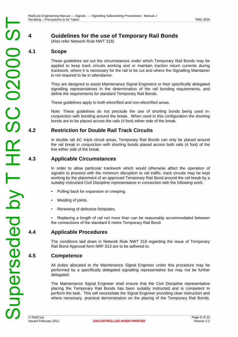
RailCorp Engineering Manual — Signals — Signalling Safeworking Procedures: Manual J Rerailing – Precautions to be Taken TMG J026
© RailCorp Page 8 of 10 Issued February 2011 UNCONTROLLED WHEN PRINTED Version 2.2
4 Guidelines for the use of Temporary Rail Bonds (Also refer Network Rule NWT 318)
4.1 Scope
These guidelines set out the circumstances under which Temporary Rail Bonds may be applied to keep track circuits working and or maintain traction return currents during trackwork, where it is necessary for the rail to be cut and where the Signalling Maintainer is not required to be in attendance.
They are designed to assist Maintenance Signal Engineers or their specifically delegated signalling representatives in the determination of the rail bonding requirements, and define the requirements for standard Temporary Rail Bonds.
These guidelines apply to both electrified and non-electrified areas.
Note: These guidelines do not preclude the use of shorting bonds being used in-conjunction with bonding around the break. When used in this configuration the shorting bonds are to be placed across the rails (4 foot) either side of the break.
4.2 Restriction for Double Rail Track Circuits
In double rail AC track circuit areas, Temporary Rail Bonds can only be placed around the rail break in conjunction with shorting bonds placed across both rails (4 foot) of the line either side of the break.
4.3 Applicable Circumstances
In order to allow particular trackwork which would otherwise affect the operation of signal/s to proceed with the minimum disruption to rail traffic, track circuits may be kept working by the placement of an approved Temporary Rail Bond around the rail break by a suitably instructed Civil Discipline representative in connection with the following work:
• Pulling back for expansion or creeping.
• Welding of joints.
• Renewing of defective fishplates.
• Replacing a length of rail not more than can be reasonably accommodated between the connections of the standard 6 metre Temporary Rail Bond.
4.4 Applicable Procedures
The conditions laid down in Network Rule NWT 318 regarding the issue of Temporary Rail Bond Approval form NRF 013 are to be adhered to.
4.5 Competence
All duties allocated to the Maintenance Signal Engineer under this procedure may be performed by a specifically delegated signalling representative but may not be further delegated.
The Maintenance Signal Engineer shall ensure that the Civil Discipline representative placing the Temporary Rail Bonds has been suitably instructed and is competent to perform the task. This will necessitate the Signal Engineer providing clear instruction and where necessary, practical demonstration on the placing of the Temporary Rail Bonds.
Sup
erse
ded
by T
HR
SC
020
00 S
T

RailCorp Engineering Manual — Signals — Signalling Safeworking Procedures: Manual J Rerailing – Precautions to be Taken TMG J026
© RailCorp Page 9 of 10 Issued February 2011 UNCONTROLLED WHEN PRINTED Version 2.2
For each issue, the Signal Engineer shall provide the Civil Representative a simple diagram depicting the placement of Temporary Rail Bonds.
The Maintenance Signal Engineer shall ensure that the Civil Discipline representative installing the Temporary Rail Bonds understands that the bonds are not to be removed until the break has been welded out or permanent bonds installed.
Where traction bonding is concerned, the Maintenance Signal Engineer shall ensure that the skill level required is not beyond the ability of the Civil Discipline representative who will be responsible for installing the Temporary Rail Bonding and there will be minimum risk to personnel or system by the work and bonding methods.
4.6 Issuing Temporary Rail Bonds
Temporary Rail Bonds shall be to an approved design fitted with approved rail clamps. The maximum length of Temporary Rail Bonds must not exceed 6 metres. (This will generally limit the maximum rail cut to approximately 4.8 metres; however this is only an approximation and is not to be taken as the specified maximum). Temporary Rail Bonds used as shorting bonds are to be limited to 2 metres in length.
Maintenance Signal Engineers are responsible for the issue of Temporary Rail Bonds, limiting their issue to two 6 metre bonds and two 2 metre bonds per work team.
Temporary Rail Bonds shall be inspected every 6 months to assess their condition and effectiveness. Where a bond is or may be used in electrified areas, special attention shall be made of the bond’s condition and where there is evidence of damage to the cable or rail clips the bond should be replaced.
Each bond and its associated rail clips are to be uniquely numbered and Maintenance Signal Engineers are to fix tags showing this number and the inspection date prior to issue and update and or renew the tags on subsequent 6 monthly inspections.
The Maintenance Signal Engineer shall keep a register specifically for the purpose of recording the above mentioned details.
4.7 Application in Electrified areas
In electrified areas special consideration shall be given to maintaining the traction return path.
In multiple line electrified areas, the Civil Discipline representative is to be instructed that only one rail may be broken at any one time between adjacent traction sub-stations.
4.8 Application in Non Electrified areas
In non electrified areas, the Civil Discipline representative is to be instructed that at any one locality, only one rail joint is to be broken or rail cut made in each rail of a line and cuts/breaks shall be made at no more than two positions at any one time. A locality for the purpose of these guidelines shall mean an area within a worksite where the breaks in the rail are opposite or in close proximity to each other.
4.9 Special Situations
Where these guidelines do not address complex situations or where circumstances arise, causing doubt as to whether these guidelines satisfactorily control the risk, the matter shall be referred to the Principal Engineer Signal Operations & Assurance for determination.
Sup
erse
ded
by T
HR
SC
020
00 S
T

RailCorp Engineering Manual — Signals — Signalling Safeworking Procedures: Manual J Rerailing – Precautions to be Taken TMG J026
© RailCorp Page 10 of 10 Issued February 2011 UNCONTROLLED WHEN PRINTED Version 2.2
This page has been intentionally left blank
Sup
erse
ded
by T
HR
SC
020
00 S
T

RailCorp Engineering Manual — Signals — Signalling Safeworking Procedures: Manual J Traction Return (1500V DC) TMG J027
© RailCorp Page 1 of 8 Issued February 2013 UNCONTROLLED WHEN PRINTED Version 2.2
TMG J027
TRACTION RETURN (1500V DC)
Version 2.2
Issued February 2013
Document control
Version Date Summary of change Replaced SC 00 52 00 27 SI Traction Return (1500V DC)
1.1 19/02/2008 Correction to cross reference in last paragraph of Section 2.8 1.2 July 2008 Correct the version number and issue date (July 2008) 1.3 3 February 2010 New Section 3 - Temporary Rail Connection of Overhead Wiring 1.4 May 2010 Application of TMA 400 format 2.0 July 2010 Replaced "General" with "Introduction".
Specified "licensed" with Signal Engineer title. Moved precautions relating to Rerailing at Sectioning Huts to TMG J026. Enhanced sections 2.1, 2.9 & 3
2.1 December 2010 New section 2 for Safe Arrangements for Working with Traction Return Current Added "sectioning huts" in 3.7.1and titled paragraph "General" Provision of additional precautions in 3.7.2
2.2 February 2013 Remove references of periodic Spark Gap maintenance inspections in section 3.8
Sup
erse
ded
by T
HR
SC
020
00 S
T
RailCorp Engineering Manual — Signals — Signalling Safeworking Procedures: Manual J Traction Return (1500V DC) TMG J027
© RailCorp Page 2 of 8 Issued February 2013 UNCONTROLLED WHEN PRINTED Version 2.2
Contents 1 Introduction .............................................................................................................................3 2 Safe Arrangements for Working with Traction Return Currents........................................3
2.1 Principles ...................................................................................................................3 2.2 Traction Return Provision ..........................................................................................4 2.3 Sub-station or Section Hut Disconnection .................................................................4 2.4 Where No Provision for Traction Return is Required ................................................4
3 Precautions When Renewing Bonds or Replacing Rails....................................................5 3.1 Broken Traction Continuity ........................................................................................5 3.2 Protection of Double Rail AC Track Circuits..............................................................5 3.3 Single Lines and Single Rail Track Circuits...............................................................5 3.4 Double Lines..............................................................................................................5 3.5 Quadruple lines..........................................................................................................5 3.6 Impedance Bonds......................................................................................................6 3.7 Traction Return Connections to Substations and Sectioning Huts ...........................6
3.7.1 General.......................................................................................................6 3.7.2 Arrangements for Continuity of Negative Connections ..............................6
3.8 Rail Spark Gap Arrestors...........................................................................................7 3.9 Electrolysis Bond Connections ..................................................................................7
4 Temporary Rail Connection of Overhead Wiring.................................................................8
Sup
erse
ded
by T
HR
SC
020
00 S
T

RailCorp Engineering Manual — Signals — Signalling Safeworking Procedures: Manual J Traction Return (1500V DC) TMG J027
© RailCorp Page 3 of 8 Issued February 2013 UNCONTROLLED WHEN PRINTED Version 2.2
1 Introduction This document describes the precautions necessary when work is performed that may affect any part of the traction return in 1500V DC electrified areas. These precautions and associated procedures shall be read in conjunction with other chapters of the Signalling Safeworking Procedures including:
• TMG J008 Booking Signalling Equipment Out of Use
• TMG J009 Disconnection of Signalling Apparatus
• TMG J025 Track Circuits
• TMG J026 Rerailing – Precautions to be Taken
The relevant requirements of Network Rule NWT 318 shall also be complied with.
In 1500V DC electrified areas, before any interference with the rails forming part of the traction return is permitted, adequate provision shall be made for the traction return current.
A safe path shall be provided for the traction current to the substation or sectioning hut.
At the same time the signalling equipment shall be safeguarded against damage due to a possible dangerous rise in traction return voltage.
2 Safe Arrangements for Working with Traction Return Currents
2.1 Principles
When breaking rails or connections to sub-stations or section huts suitable provision needs to be made that the traction current is provided for and that unsafe voltages do not develop across rail or cable breaks.
There are two specific situations that are required to be made safe by different methods.
These are, firstly, where rails need to be removed, and secondly, where substation or section hut connections are to be disconnected.
Whenever the break is confined to a single rail or single cable before the break is made, confirmation is to be obtained that an alternate path is functional. This may require the placing of temporary bonding around the break.
Temporary traction bonding is direct (rail to rail) and should not be run along the track for any distance.
Where the break is to occur on all rails, or a sub-station or section hut is to be completely disconnected, it will be necessary to make alternate arrangements to ensure traction return is provided for and unsafe voltages do not develop.
Sup
erse
ded
by T
HR
SC
020
00 S
T

RailCorp Engineering Manual — Signals — Signalling Safeworking Procedures: Manual J Traction Return (1500V DC) TMG J027
© RailCorp Page 4 of 8 Issued February 2013 UNCONTROLLED WHEN PRINTED Version 2.2
2.2 Traction Return Provision
Traction currents may flow between areas either side of the work area. This traction may be provided for by:
• Rail connecting the OHW at each end of the work area; or
• Laying an additional rail in the cess and bonding this to the remaining rails either side of the worksite, or connecting to an adjacent, unaffected line.
Where the overhead wiring rail connection is used, care must be taken to:
• Bond locally across traction rails at the break so the OHW rail connection is effective on all traction rails,
• Not break any rails until the connection is in place
• Ensure the Signals representative takes an Electrical Permit to Work, to ensure the OHW rail connections are not removed until the normal rail and bonding is restored.
• Ensure the OHW remains continuous during the work.
In all cases, the Signals representative is to monitor and ensure that all temporary arrangements remain in place.
2.3 Sub-station or Section Hut Disconnection
In all cases of a complete disconnection of sub-station, or section hut rail connections, the Signal representative must sign onto an Electrical Permit to Work before work commences and must not release it until the new cables and connections have been restored and certified.
2.4 Where No Provision for Traction Return is Required
Where the absence of traction return is assured, then no additional bonding or protection is required to assure safety.
In these cases the absence of traction return is assured by:
• A new railway being constructed where either end is not connected to a working railway and there is no energised overhead wiring over, or adjacent to, the track.
• An isolation of an existing railway branch line where the last sub-station is rail connected and an Electrical Permit to Work has been issued to the Signals representative, and there is no electric traction in use between that point and the end of the line.
• Removal of track in an area where the Signals representative has signed onto an Electrical Permit to Work for the area, and no electric traction can operate near or past the site on adjacent tracks.
Sup
erse
ded
by T
HR
SC
020
00 S
T

RailCorp Engineering Manual — Signals — Signalling Safeworking Procedures: Manual J Traction Return (1500V DC) TMG J027
© RailCorp Page 5 of 8 Issued February 2013 UNCONTROLLED WHEN PRINTED Version 2.2
3 Precautions When Renewing Bonds or Replacing Rails 3.1 Broken Traction Continuity
If the traction continuity of both rails in one or more tracks at a location is found to have been broken, all rails adjoining the break must be assumed to be live at traction voltage until it can be established that traction continuity is maintained through bonding further along the track.
3.2 Protection of Double Rail AC Track Circuits
Before any interference with the rails forming part of the traction return circuit on a track circuited line is permitted, the feed and relay of the track circuit shall be disconnected at the outgoing terminals in accordance with Signalling Safeworking Procedure TMG J009.
This action isolates the equipment from a rise in D.C. traction current and eliminates a source of possible circulating A.C. track circuit current.
3.3 Single Lines and Single Rail Track Circuits
On a single line track or on the traction rail of a single rail track circuit, before the fishplates or the bond of a bonded rail joint are taken off, the rails on each side of the joint shall be connected together by means of temporary traction jumper bonds.
Before a rail is removed from a single line track or before the traction rail is removed from a single rail track, temporary jumper bonds shall be provided and connected for an alternative traction return path to take the place of the rail which is to be removed.
Both rails of a single line or of a single rail track circuit shall not be broken at any one time until an alternate path is provided. Signalling Maintainers shall refer all such cases to a licensed Signal Engineer for direction regarding the special arrangements necessary.
3.4 Double Lines
On double lines, where the four rails are used for traction return, the continuity of the circuit shall not be broken in more than one of these four rails in the section between any two adjacent cross bonds at any one time.
3.5 Quadruple lines
On quadruple lines, where the eight rails are used for the traction return, the continuity of the circuit shall not be broken in more than two of these eight rails in the section between any two adjacent cross bonds at any one time.
Note:
The requirements stipulated in sections 3.3, 3.4 & 3.5 are the minimum rail requirements to ensure a low resistance path is provided for the traction return currents. However circumstances may arise where it is not possible, due to the nature of the work, to provide the minimum rail requirement. Where such circumstances arise, the matter is to be referred to the Maintenance Signal Engineer for determination of the traction return current arrangements. The Maintenance Signal Engineer is to liaise with the Principal Engineer Signal Design to ensure and agree on the proposed traction return arrangements, this may necessitate temporary track bonding design being issued where a level of complexity exist or as determined by the Principal Engineer Signal Design, in accordance with the principles in section 2.
Sup
erse
ded
by T
HR
SC
020
00 S
T

RailCorp Engineering Manual — Signals — Signalling Safeworking Procedures: Manual J Traction Return (1500V DC) TMG J027
© RailCorp Page 6 of 8 Issued February 2013 UNCONTROLLED WHEN PRINTED Version 2.2
3.6 Impedance Bonds
Before an impedance bond is disconnected, the feed and relay of the track concerned shall be disconnected and temporary bonding connections provided for traction return between the neutral point of the impedance bond of the adjacent track circuit and one of the rails of the track circuit from which the bond is to be disconnected. Where the adjacent track circuit is single rail, the same effect can be obtained by connecting one of the rails to the traction rail of the adjacent single rail track circuit.
3.7 Traction Return Connections to Substations and Sectioning Huts
3.7.1 General
The traction return to substations and sectioning huts is provided by cables connecting either direct to the rail in the case of single rail track circuits or on non track circuited lines, or via impedance bonds in the case of double rail track circuits.
Under no circumstances shall the traction return connections from the track to the substation or sectioning hut be broken without providing an adequate return to the substation or sectioning hut or otherwise obtaining an isolation of the 1500 DC traction by the Signals representative signing onto an Electrical Permit to Work.
In all cases of work being carried out at the negative connections at substations or sectioning huts, the Electrical discipline shall be advised.
Temporary arrangements shall be confirmed by a licensed Signal Engineer.
3.7.2 Arrangements for Continuity of Negative Connections
At substations and sectioning switch locations of the 1500V DC overhead supply, at least two (2) negative cable connections are provided from the traction rails.
Before either cable is disconnected, a representative from the Electrical discipline should confirm the continuity and effectiveness of the remaining cable and connection.
The location of negative cable connections is indicated by a notice plate, generally attached to the sleepers, the inscription reading "Danger 1500 volt negative, do not break cable".
Care should always be exercised in the maintenance of these connections as a break in the cables would result in a potential difference of 1500 volts across the break.
Older Sectioning Hut installations:
Two negative cable connections are made to the same rail, on either side of a mechanical joint.
• No more than one negative cable shall be disconnected at the same time.
• If a negative cable connection cannot be maintained, isolation of the 1500V DC traction is required by the Signals representative signing onto an Electrical Permit to Work.
Sup
erse
ded
by T
HR
SC
020
00 S
T

RailCorp Engineering Manual — Signals — Signalling Safeworking Procedures: Manual J Traction Return (1500V DC) TMG J027
© RailCorp Page 7 of 8 Issued February 2013 UNCONTROLLED WHEN PRINTED Version 2.2
Substation and newer Sectioning Hut installations:
Negative cable connections are made to all traction rails.
On multi-track lines, the Electrical discipline's usual practice is to provide negative busbars on both sides of the tracks, for termination of the rail connections. The substation or sectioning hut location is also used as a traction tie-in location.
On double rail tracks the negative cable connections are made by impedance bonds.
On single rail tracks the negative cable connections are made directly to the traction rail. A mechanical joint need not be provided so long as at least one busbar connection can be maintained at all times.
• No more than one set of negative cable connections from impedance bond or rail to the substation or sectioning hut busbar/s shall be broken at the same time.
• If all negative cable connections cannot be maintained, isolation of the 1500V DC traction is required by the Signals representative signing onto an Electrical Permit to Work, before any connection is broken.
3.8 Rail Spark Gap Arrestors
Certain overhead metal structures to which 1500V DC wiring is attached are provided with a rail spark gap arrestor and a cable connection to the traction return rail. In cases where a spark gap connection to rail is found to have become broken, or requires disconnection, the overhead structure and the cable connected to it must be treated as being live at traction voltage, until such time as it has been tested and declared safe by a representative of the Electrical discipline, in accordance with instruction ETN 04/05 OHW Structure to Rail Bonding.
During routine examination of track circuits any spark gap connection cables which pass under the rails shall be examined for insulation damage and reported to the Maintenance Supervisor if deterioration has occurred.
3.9 Electrolysis Bond Connections
At certain locations indicated on the bonding plans a negative connection is provided to the neutral point of an impedance bond or a special transformer for the purpose of providing a low resistance one way path for "earth" leakage current from adjacent power and telephone cables, gas and water mains, the connection being made through what is known as an electrolysis bond. These connections can also be made to the traction rail of single rail track circuits. These connections shall be carefully checked and maintained at all times.
Sup
erse
ded
by T
HR
SC
020
00 S
T

RailCorp Engineering Manual — Signals — Signalling Safeworking Procedures: Manual J Traction Return (1500V DC) TMG J027
© RailCorp Page 8 of 8 Issued February 2013 UNCONTROLLED WHEN PRINTED Version 2.2
4 Temporary Rail Connection of Overhead Wiring During any work that requires the 1500V traction supply to be isolated, and except where permanent overhead sectioning/earthing switches have been installed, there will be a requirement to provide temporary rail connections from the overhead wiring.
The licensed Signal Engineer shall, upon a request from the Electrical discipline, identify an appropriate connection point by marking a copy of the track insulation plan with the location where the temporary connection may be made, and providing this to the electrical discipline.
Where there is doubt about a correct connection being made a signal representative should attend to supervise the connection.
No connections shall be made unless the licensed Signal Engineer has agreed to the connection, or it is on a formally approved track insulation plan issued by Signal Design.
The licensed Signal Engineer shall ensure that the temporary connections are only made as follows:
• To the traction rail of a single rail track circuit; or
• To the neutral point of an audio frequency track circuit, or neutral point of an impedance bond for a double rail track circuit, or
• Direct to a rail of an audio frequency track circuit or double rail track circuit, but only if that track circuit is not required to be energised during the work
The connection point shall be a secure point external to any work taking place in the possession to ensure traction return to the substation is not affected.
If the track circuit is to be de-energised in conjunction with this connection, the track circuit shall be booked out of order and disconnected. In this case, care shall be taken to identify any points or other signalling equipment that may be required as operational during the time the connection is made, to avoid disruption to the movement of track machines and trains.
At the completion of the work the Electrical discipline is responsible for the removal of all temporary connections and if necessary, the licensed Signal Engineer will arrange for the reconnection and booking in of any affected track circuits.
Sup
erse
ded
by T
HR
SC
020
00 S
T

RailCorp Engineering Manual — Signals — Signalling Safeworking Procedures: Manual J Facing Point Lock and Detector Testing - Mechanical TMG J029
© RailCorp Page 1 of 4 Issued May 2010 UNCONTROLLED WHEN PRINTED Version 1.5
TMG J029
FACING POINT LOCK AND DETECTOR TESTING - MECHANICAL
Version 1.5
Issued May 2010
Document control
Version Date Summary of change Replaced SC 00 52 00 29 SI Facing Point Lock Testing -
Mechanical. 1.1 6 March 2007 Amendment of second sentence in item 2b. 1.2 4 September 2007 Addition of Sections 3 & 4. 1.3 July 2009 Addition of ‘Facing Point Lock’ and ‘Points Lock Detectors
(HLM)’ Adjustment Sub Sections and removal of ‘Use of Points Lock Detectors (HLM)’ Section.
1.4 November 2009 Correct reference in Section 3 1.5 May 2010 Application of TMA 400 format
Contents 1 General Procedure ..................................................................................................................2 2 Adjustments ............................................................................................................................2
2.1 Facing Point Lock ......................................................................................................2 2.2 Points Lock Detectors (HLM).....................................................................................3
3 Electrical Point Detectors on Mechanical Points ................................................................4
Sup
erse
ded
by T
HR
SC
020
00 S
T
RailCorp Engineering Manual — Signals — Signalling Safeworking Procedures: Manual J Facing Point Lock and Detector Testing - Mechanical TMG J029
© RailCorp Page 2 of 4 Issued May 2010 UNCONTROLLED WHEN PRINTED Version 1.5
1 General Procedure Point locks shall be periodically tested to ensure the reliable operation of the points and that with the lock engaged the switches are held within 3.2mm of the running face of the stock rail, and to ascertain if the slide chairs in the vicinity of the points rodding have worn, or the stock rails have worn, or the track gauge has varied.
The lock plunger travel is to be 200mm, except in the case of double lock plungers worked by one lever, where the travel is 175mm. When the lock plunger is withdrawn the clearance between the end of the lock plunger and the slotted lock rod or locking rod block is to be 20mm. For the point lock detector the lock must enter in the notches with clearance on both sides.
When gauge testing a facing point lock the 3.2mm gauge shall be used and the lock shall be maintained sufficiently tight to ensure that the movement of the F.P.L. lever cannot be completed with the gauge inserted between the point switch and the stock rail in line with the stretcher at the toe of the points. The switch shall be operated by means of the lever in the interlocking machine. When the F.P.L. locks the points both ways, each switch shall be tested.
When gauge testing a point lock detector the 3.2mm gauge shall be used and the lock shall be maintained sufficiently tight to ensure that the lock does not engage with the gauge inserted between the point switch and the stock rail in line with the stretcher at the toe of the points. The switch shall be operated by means of the lever in the interlocking machine. When the facing point lock detector locks the points both ways, each switch shall be tested.
Some locations as follows may have special arrangements where a wider notch is permitted in the point lock detector:
• Lithgow 3.2mm gauge go, 4.8mm gauge no go.
The Signalling Maintainer shall confirm that the track is to gauge at the points, looking for signs of excessive wear or movement of the track that would affect the safe or reliable operation of the points equipment.
The Signalling Maintainer shall notify the Civil representative of any undue movement or wear of the track at the points and request rectification of same.
In routine testing of point locks and point detection, the Signalling Maintainer carrying out the tests shall liaise with the signaller so that the testing is conducted without detriment to safety or train working.
The Signalling Maintainer carrying out the tests shall arrange for the signals protecting the points concerned to be securely maintained at stop during testing.
Where adjustment is required the signals protecting the points are to be booked out of use for traffic movements in accordance with Network Rule NWT 312 and Procedure NPR 704.
2 Adjustments 2.1 Facing Point Lock
If, during testing under normal operation, the switches do not fit hard up against the stockrail with some spring then the points drive may need adjustment.
Sup
erse
ded
by T
HR
SC
020
00 S
T
RailCorp Engineering Manual — Signals — Signalling Safeworking Procedures: Manual J Facing Point Lock and Detector Testing - Mechanical TMG J029
© RailCorp Page 3 of 4 Issued May 2010 UNCONTROLLED WHEN PRINTED Version 1.5
If, during testing under normal operation, the facing point lock plunger is tight with the point switch blades fitting hard up against the stock-rail then the points may need adjustment.
If, during gauge testing it is found that the facing point lock lever can be put fully home with the gauge between the point switch and stock-rail, then adjustment is necessary.
Before adjustment ensure that there is no movement due to loose F.P.L casting or movement of stockrail or chairs.
Adjustment shall be immediately made as follows:
a) Loosen the two bolts at the joint in the lock rod, sufficiently to allow the disengagement of the serrations. Adjust the lock rod bar accordingly and re- engage the serrations at the required new position. Tighten the bolts.
b) If the required adjustment is less than that provided by the serrations, or if the lock rod is of the non-serrated type, shims shall be used. These are to be inserted between the switch and the lock rod.
c) If the extent of the wear is such that a properly adjusted lock cannot be obtained the worn fittings shall be replaced.
A facing point lock return shall be provided as and when locks are tested or on a regular period basis for locks tested during that period and then forwarded to the Maintenance Signal Engineer. Details of adjustments made shall be included in the return. The period should be at least monthly.
2.2 Points Lock Detectors (HLM)
If, during testing under normal operation, the switches do not fit hard up against the stockrail with some spring then the points drive may need adjustment.
If, during testing under normal operation, the facing point detector lock is not in the centre of the notch with the point switch blades fitting hard up against the stock-rail then the points may need adjustment.
Before adjustment ensure all fastenings are tight, especially the sleeper and bedplate fixings, and rodding.
Where the travel on the lock slide is insufficient or excessive, adjustment shall be immediately made as follows:
a) Loosen the two bolts at the joint in the lock rod, sufficiently to allow the disengagement of the serrations. Adjust the lock rod bar accordingly and re- engage the serrations at the required new position. Tighten the bolts.
b) If the required adjustment is less than that provided by the serrations, or if the lock rod is of the non-serrated type, shims shall be used. These are to be inserted between the switch and the lock rod.
c) If the extent of the wear is such that a properly adjusted lock cannot be obtained the worn fittings shall be replaced.
d) If the lock is not in the centre of the slide, adjust the lock rod to correctly centre the notch around the lock.
A facing point detector return shall be provided as and when locks are tested or on a regular period basis for locks tested during that period and then forwarded to the
Sup
erse
ded
by T
HR
SC
020
00 S
T

RailCorp Engineering Manual — Signals — Signalling Safeworking Procedures: Manual J Facing Point Lock and Detector Testing - Mechanical TMG J029
© RailCorp Page 4 of 4 Issued May 2010 UNCONTROLLED WHEN PRINTED Version 1.5
Maintenance Signal Engineer. Details of adjustments made shall be included in the return. The period should be at least monthly.
3 Electrical Point Detectors on Mechanical Points The adjustment of the point detectors shall be as per Sections 1.6.1, 1.6.3, 1.7 and 1.8 of TMG J030 – Facing Point Lock and Detection Testing on Power Operated Points.
Sup
erse
ded
by T
HR
SC
020
00 S
T

RailCorp Engineering Manual — Signals — Signalling Safeworking Procedures: Manual J Facing Point Lock and Detection Testing on Power Operated Points TMG J030
© RailCorp Page 1 of 10 Issued December 2012 UNCONTROLLED WHEN PRINTED Version 1.7
TMG J030
FACING POINT LOCK AND DETECTION TESTING ON POWER
OPERATED POINTS
Version 1.7
Issued December 2012
Document control
Version Date Summary of change 1.0 12/09/2005 Replaced SC 00 52 00 30 SI Facing Point Lock and Detection
Testing – Combined Point Machine 1.1 04/09/2007 Title amended, changed to be a generic document and TMG J028
deleted 1.2 August 2008 Added reference to Claw Lock manual in Section 1.5.2 1.3 July 2009 Parameter made generic in Section 1.1, return requirements in
Section 1.3, new reference for HLM point lock detectors on EP swing nose crossings in Sections 1.11 & 1.12 and formatting update
1.4 September 2009 Removed reference to U5A detector from Section 1.10.1. 1.5 May 2010 Application of TMA 400 format 1.6 August 2011 Added reference to Removal of Lock-Slides and provision for
Wide-cut Notch on Lock-Slides. Appropriately renumbered paragraphs in this document.
1.7 December 2012 Better describe the different methods of testing EP Clawlock & Spherolock point operating bar detection in 5.1, 5.2 & 5.3. Tests only required after initial set up and as described.
Contents 1 Introduction .............................................................................................................................3
1.1 Aim of Points Maintenance........................................................................................3 1.2 Points Adjustment Strategy .......................................................................................3 1.3 Maintenance Inspections...........................................................................................3 1.4 Safety Arrangements for Points Testing and Adjustments........................................3
2 Facing Point Lock Testing and Adjustment .........................................................................4 2.1 Conventional Type Mechanisms ...............................................................................4
2.1.1 Provision for Removal of Lock-Slides ........................................................4 2.1.2 Provision for a Wide-Cut Lock-Slide ..........................................................4
Sup
erse
ded
by T
HR
SC
020
00 S
T

RailCorp Engineering Manual — Signals — Signalling Safeworking Procedures: Manual J Facing Point Lock and Detection Testing on Power Operated Points TMG J030
© RailCorp Page 2 of 10 Issued December 2012 UNCONTROLLED WHEN PRINTED Version 1.7
2.1.3 Requirements for Removal of Lock-Slides or Provision of a Wide-Cut Lock-Slide...................................................................................5
2.2 Claw Lock Mechanisms.............................................................................................6 2.3 Spherolock Mechanisms............................................................................................6
3 Detection of Switches.............................................................................................................6 3.1 Actions requiring Detection Adjustment.....................................................................6 3.2 Machines with Interlocked FPL and Detection ..........................................................7 3.3 Setting of Detection contacts.....................................................................................7 3.4 Westinghouse 84M & HM Detectors .........................................................................8 3.5 Increase of Detection Settings on Trailing-Only Points and
Catchpoints................................................................................................................8 4 Back Drive detectors ..............................................................................................................8 5 Detection of Operating Bars (Claw Lock and Spherolock).................................................8
5.1 EP Points ...................................................................................................................9 5.2 EP Catchpoints and Independent Switches ..............................................................9 5.3 EP Point Motors fitted with Micro Switches ...............................................................9 5.4 84M Type Machines ..................................................................................................9
6 Locking of Operating Bars.....................................................................................................9 7 Swing Nose Crossings ...........................................................................................................9
Sup
erse
ded
by T
HR
SC
020
00 S
T

RailCorp Engineering Manual — Signals — Signalling Safeworking Procedures: Manual J Facing Point Lock and Detection Testing on Power Operated Points TMG J030
© RailCorp Page 3 of 10 Issued December 2012 UNCONTROLLED WHEN PRINTED Version 1.7
1 Introduction 1.1 Aim of Points Maintenance
All point machines shall be periodically tested to ensure the reliable operation of the points and that, with the facing point lock engaged the switches are held within specified limits of the running face of the stock rail
1.2 Points Adjustment Strategy
Older types of point mechanisms had the detection contacts mechanically interlocked with the facing point lock such that it was not possible to obtain detection with the lock not plunged. Later point mechanisms may have separate independent lock and detector contacts. For Claw Lock and Spherolock type operating mechanisms, an assurance of locking is determined by the position of the drive bar.
In all cases (except Claw Lock mechanisms – ref 2.2) the lock is adjusted to provide a 'go' setting of 1.6mm switch opening and a 'no-go' setting of 3.2mm switch opening. The switch detection is complementary and should be just made at 3.2mm and broken at 4.8mm switch opening.
These settings ensure that when a switch lock is correctly set within these limits, detector contacts are firmly made and will not ‘bounce’ with train passage over the points.
1.3 Maintenance Inspections
Facing point lock returns shall be provided in accordance with TMG J017 Maintenance Responsibilities, Frequencies, Recording for locks tested during the maintenance period and forwarded to the Maintenance Signal Engineer. Additionally, a return shall be provided following any out of course adjustment/test made between routine maintenance inspections.
The Signalling Maintainer shall confirm that the track is correct to gauge at the points, looking for signs of excessive wear or movement of the track that would affect the reliable operation of the points equipment. In particular, wear on the slide chairs or the foot of the switch shall be inspected.
The Signalling Maintainer shall notify the Civil representative of any undue movement or wear of the track at the points and request and follow up rectification.
1.4 Safety Arrangements for Points Testing and Adjustments
In routine testing of facing point locks and point detection, the Signalling Maintainer carrying out the tests shall liaise with the signaller so that the testing is conducted without detriment to safety or train working. The signaller is to place affected controlled signals at stop before the testing is allowed to commence.
The Signalling Maintainer carrying out the tests shall either use the ESML or EOL or Plug Connector and Key arrangements where available, or arrange for the signals protecting the points concerned to be otherwise securely maintained at stop during testing.
Where Plug Connector and Key or manual actuator arrangements for Style E or ES electro pneumatic points are used, or where ESML or EOL arrangements are used, the signals protecting the points concerned must first be placed at stop and approaching trains brought to a stand before the Plug Connector is disconnected or the ESML or EOL keys are taken.
Sup
erse
ded
by T
HR
SC
020
00 S
T

RailCorp Engineering Manual — Signals — Signalling Safeworking Procedures: Manual J Facing Point Lock and Detection Testing on Power Operated Points TMG J030
© RailCorp Page 4 of 10 Issued December 2012 UNCONTROLLED WHEN PRINTED Version 1.7
Where the ESML, EOL or Plug Connector and Key arrangements are not being used and adjustment is required, the signals protecting the points are to be booked out of use for traffic movements in accordance with Network Rule NWT 312 and Procedure NPR 704 before commencing adjustment.
2 Facing Point Lock Testing and Adjustment 2.1 Conventional Type Mechanisms
The points shall be operated both normal and reverse to see if the switches fit hard up against the stock rail and if the point lock plunger enters and withdraws from the notch freely and with sufficient clearance. Adjustments shall be made as necessary.
Electric motor operated points shall be operated by hand using the applicable ESML handle (and maintenance handle where provided) or the hand throw lever for point machines so equipped.
The facing point lock shall be tested in accordance with the procedure laid down for the particular type of points machine in the Points Equipment Manuals. Avoid switch roll as far as possible as this will introduce error into the test.
The facing point lock test shall be carried out using in turn gauges for openings of 3.2mm and 1.6mm between the stockrail running face and the switch at a position approximately, and not more than, 75mm back from the tip of a conventional type of switch. For asymmetric type rail sections, the test position shall be in line with the drive rod connection.
The lock shall not enter with a switch opening of 3.2mm, but shall enter with a switch opening of 1.6mm.
Ideally, on those machines with the locking notch approximately 3.2mm wider than the locking dog, the locking dog should be centred in the notch with the switch closed against the stockrail. This situation will avoid lock wear and tight locks on both locking and non-locking sides and will comply with the go, no-go figures specified above.
2.1.1 Provision for Removal of Lock-Slides
In certain circumstances, where the reliability of trailing only points can be improved by the removal of the facing point lock slides, then it may be permissible to implement such arrangement subject to the approval and adherence of the requirements in accordance with ESG 100.14 Signal Design Principles – Points and the requirements listed in section 2.1.3 below.
This provision only applies for the following arrangements:
• Trailing Only points (both directions) operated by a Combined Electric Switch Machine.
2.1.2 Provision for a Wide-Cut Lock-Slide
In certain circumstances, where the reliability of points can be improved by the provision of a wide-cut notch in the facing point lock-slide, then it may be permissible to implement such arrangement subject to approval and adherence of the requirements in accordance with ESG 100.14 Signal Design Principles – Points and the requirements listed in section 2.1.3 below.
Sup
erse
ded
by T
HR
SC
020
00 S
T
RailCorp Engineering Manual — Signals — Signalling Safeworking Procedures: Manual J Facing Point Lock and Detection Testing on Power Operated Points TMG J030
© RailCorp Page 5 of 10 Issued December 2012 UNCONTROLLED WHEN PRINTED Version 1.7
This provision only applies for the following arrangements:
• The Open switch on catchpoints operated by Combined Electric Switch machines • The Open switch on catchpoints operated by Signal Branch EP assemblies • The Trailing Only position operated by Signal Branch EP assemblies
This permits a coarser adjustment of the detection as referenced in 3.5.
2.1.3 Requirements for Removal of Lock-Slides or Provision of a Wide-Cut Lock-Slide
• Where the removal of Lock-Slides is approved for Trailing ONLY points operated by Combined Electric Switch Machines:
(a) The unused guideways on both sides of the machine are to be plugged to prevent entry of dust and grit.
(b) The Signal Maintenance Engineer shall maintain a register of switch machines with lock-slides removed for the maintenance district.
• Where the provision of a Wide-Cut Notch is approved for the Open switch on a
catchpoint operated by Combined Electric Switch Machine: (a) The allowable cut-out for the wide-cut notch shall not exceed 13mm
wider then the respective locking dog, conforming to the requirements of section 3.5 for the increase of detector settings.
(b) Facing Point Lock Adjustment: The Open switch facing point lock shall be typically adjusted to be
in the centre of the notch, but in any case, the lock shall not enter with a switch opening of 100mm or less. (Note the Closed switch lock shall be adjusted in accordance with section 1.2).
(c) The lock-slide shall be stamped “Wide Cut Notch” together with the applicable point end number - all in 6mm letters.
(d) The stamped text shall be adjacent to the wide-cut notch on one side of the slide and on the top and bottom face at the end between the elongated slot and second hole.
(e) An additional set of lines shall be inscribed on the opposite face corresponding to the new wide-cut notch and the old marks shall be stamped with a cross.
(f) The wide-cut notch shall be machined at an engineering machine shop.
(g) Installation of modified lock-slides shall be controlled by the Signal Maintenance Engineer and certified on installation by a suitably licensed Signal Engineer.
(h) The Signal Maintenance Engineer shall maintain a register of all point machines fitted with a wide-cut notch lock-slide for the maintenance district.
(i) The Signal Engineer, as part of the 2 yearly mechanical interlocking inspection, shall inspect the lock-slides of points with wide-cut notches to ensure the integrity of the arrangement is maintained and that the inscriptions are in accordance with the signal plan or working sketch.
(j) The lock-slide with a wide-cut notch shall always belong to its respective point-end at the specified location, or otherwise when made redundant, shall be destroyed.
Sup
erse
ded
by T
HR
SC
020
00 S
T
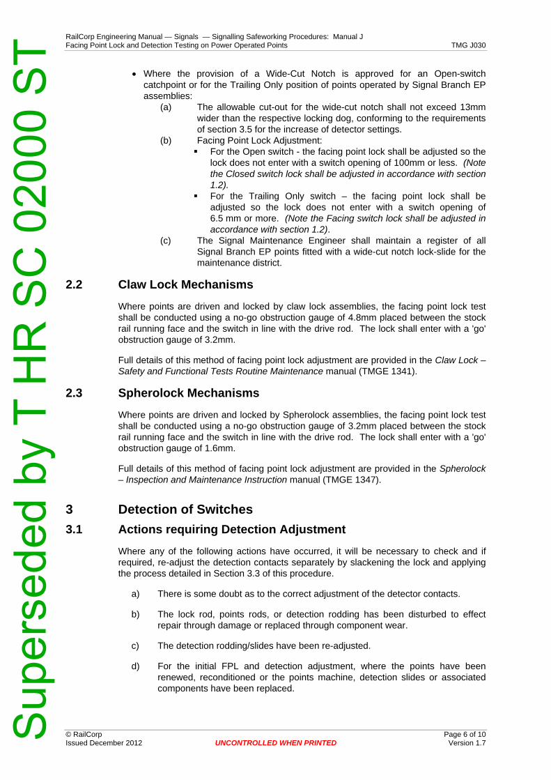
RailCorp Engineering Manual — Signals — Signalling Safeworking Procedures: Manual J Facing Point Lock and Detection Testing on Power Operated Points TMG J030
© RailCorp Page 6 of 10 Issued December 2012 UNCONTROLLED WHEN PRINTED Version 1.7
• Where the provision of a Wide-Cut Notch is approved for an Open-switch catchpoint or for the Trailing Only position of points operated by Signal Branch EP assemblies:
(a) The allowable cut-out for the wide-cut notch shall not exceed 13mm wider than the respective locking dog, conforming to the requirements of section 3.5 for the increase of detector settings.
(b) Facing Point Lock Adjustment: For the Open switch - the facing point lock shall be adjusted so the
lock does not enter with a switch opening of 100mm or less. (Note the Closed switch lock shall be adjusted in accordance with section 1.2).
For the Trailing Only switch – the facing point lock shall be adjusted so the lock does not enter with a switch opening of 6.5 mm or more. (Note the Facing switch lock shall be adjusted in accordance with section 1.2).
(c) The Signal Maintenance Engineer shall maintain a register of all Signal Branch EP points fitted with a wide-cut notch lock-slide for the maintenance district.
2.2 Claw Lock Mechanisms
Where points are driven and locked by claw lock assemblies, the facing point lock test shall be conducted using a no-go obstruction gauge of 4.8mm placed between the stock rail running face and the switch in line with the drive rod. The lock shall enter with a 'go' obstruction gauge of 3.2mm.
Full details of this method of facing point lock adjustment are provided in the Claw Lock – Safety and Functional Tests Routine Maintenance manual (TMGE 1341).
2.3 Spherolock Mechanisms
Where points are driven and locked by Spherolock assemblies, the facing point lock test shall be conducted using a no-go obstruction gauge of 3.2mm placed between the stock rail running face and the switch in line with the drive rod. The lock shall enter with a 'go' obstruction gauge of 1.6mm.
Full details of this method of facing point lock adjustment are provided in the Spherolock – Inspection and Maintenance Instruction manual (TMGE 1347).
3 Detection of Switches 3.1 Actions requiring Detection Adjustment
Where any of the following actions have occurred, it will be necessary to check and if required, re-adjust the detection contacts separately by slackening the lock and applying the process detailed in Section 3.3 of this procedure.
a) There is some doubt as to the correct adjustment of the detector contacts.
b) The lock rod, points rods, or detection rodding has been disturbed to effect repair through damage or replaced through component wear.
c) The detection rodding/slides have been re-adjusted.
d) For the initial FPL and detection adjustment, where the points have been renewed, reconditioned or the points machine, detection slides or associated components have been replaced.
Sup
erse
ded
by T
HR
SC
020
00 S
T
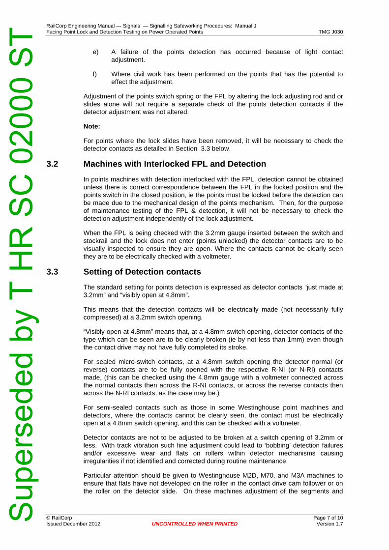
RailCorp Engineering Manual — Signals — Signalling Safeworking Procedures: Manual J Facing Point Lock and Detection Testing on Power Operated Points TMG J030
© RailCorp Page 7 of 10 Issued December 2012 UNCONTROLLED WHEN PRINTED Version 1.7
e) A failure of the points detection has occurred because of light contact adjustment.
f) Where civil work has been performed on the points that has the potential to effect the adjustment.
Adjustment of the points switch spring or the FPL by altering the lock adjusting rod and or slides alone will not require a separate check of the points detection contacts if the detector adjustment was not altered.
Note:
For points where the lock slides have been removed, it will be necessary to check the detector contacts as detailed in Section 3.3 below.
3.2 Machines with Interlocked FPL and Detection
In points machines with detection interlocked with the FPL, detection cannot be obtained unless there is correct correspondence between the FPL in the locked position and the points switch in the closed position, ie the points must be locked before the detection can be made due to the mechanical design of the points mechanism. Then, for the purpose of maintenance testing of the FPL & detection, it will not be necessary to check the detection adjustment independently of the lock adjustment.
When the FPL is being checked with the 3.2mm gauge inserted between the switch and stockrail and the lock does not enter (points unlocked) the detector contacts are to be visually inspected to ensure they are open. Where the contacts cannot be clearly seen they are to be electrically checked with a voltmeter.
3.3 Setting of Detection contacts
The standard setting for points detection is expressed as detector contacts “just made at 3.2mm” and “visibly open at 4.8mm”.
This means that the detection contacts will be electrically made (not necessarily fully compressed) at a 3.2mm switch opening.
“Visibly open at 4.8mm” means that, at a 4.8mm switch opening, detector contacts of the type which can be seen are to be clearly broken (ie by not less than 1mm) even though the contact drive may not have fully completed its stroke.
For sealed micro-switch contacts, at a 4.8mm switch opening the detector normal (or reverse) contacts are to be fully opened with the respective R-NI (or N-RI) contacts made, (this can be checked using the 4.8mm gauge with a voltmeter connected across the normal contacts then across the R-NI contacts, or across the reverse contacts then across the N-RI contacts, as the case may be.)
For semi-sealed contacts such as those in some Westinghouse point machines and detectors, where the contacts cannot be clearly seen, the contact must be electrically open at a 4.8mm switch opening, and this can be checked with a voltmeter.
Detector contacts are not to be adjusted to be broken at a switch opening of 3.2mm or less. With track vibration such fine adjustment could lead to ‘bobbing’ detection failures and/or excessive wear and flats on rollers within detector mechanisms causing irregularities if not identified and corrected during routine maintenance.
Particular attention should be given to Westinghouse M2D, M70, and M3A machines to ensure that flats have not developed on the roller in the contact drive cam follower or on the roller on the detector slide. On these machines adjustment of the segments and
Sup
erse
ded
by T
HR
SC
020
00 S
T

RailCorp Engineering Manual — Signals — Signalling Safeworking Procedures: Manual J Facing Point Lock and Detection Testing on Power Operated Points TMG J030
© RailCorp Page 8 of 10 Issued December 2012 UNCONTROLLED WHEN PRINTED Version 1.7
cams on the contact drive is not to be carried out on-site as a maintenance task and, if such adjustment is required, the complete assembly must be removed and adjusted under workshop conditions.
Signalling Maintainers are to use gauges for openings of 3.2mm and 4.8mm between the stockrail running face and the switch (at a position approximately, and not more than, 75mm from the tip) to test for correct detection adjustments.
3.4 Westinghouse 84M & HM Detectors
A common semi-sealed contact block, but with contacts that are able to be inspected, is in use in these detectors.
Detection testing is by using a 1mm ‘go’ and 2mm ‘no-go’ gauge inserted between the switch roller and the slide notch, with the switch closed hard against the stockrail. Full details of this method of detection adjustment are provided in the Claw Lock – Safety and Functional Tests Routine Maintenance manual (TMGE 1341).
3.5 Increase of Detection Settings on Trailing-Only Points and Catchpoints
With trailing points it may be permissible to increase the detection limit from 4.8mm up to 6.4 mm under certain circumstances as follows:
a) This increased limit is necessary to avoid failures and delays to traffic.
b) There is no signalled move through the trailing points in the facing direction.
c) There is no reversing move where part of the train would set back through the points in a facing direction.
d) The condition causing the inability to obtain reliable detection at the lower limits is to receive attention to correct the problem.
e) An approved Signal Design has been obtained by denoting the arrangement in the relevant Signal Plan or Working Sketch.
f) A record is kept of such arrangements in the Maintenance Signal Engineer’s Office and monitored by the Maintenance Signal Engineer.
On single blade catchpoints, detection of the open switch position, usually the normal position may be coarsely adjusted to make at about 13mm, measured from the switch stop, ie with the points open at least 100mm.
4 Back Drive detectors Backdrive detectors, where fitted should be adjusted to be broken at approximately 6.4mm switch opening (at the backdrive detector) and be made with a switch opening of 4.8 mm (at the backdrive detector).
A flange way switch opening of 60mm +/- 5mm is to be maintained.
5 Detection of Operating Bars (Claw Lock and Spherolock) When point mechanisms are used that require the operating bar to be maintained in position to guarantee the lock is maintained, this operating bar is detected in position.
Sup
erse
ded
by T
HR
SC
020
00 S
T

RailCorp Engineering Manual — Signals — Signalling Safeworking Procedures: Manual J Facing Point Lock and Detection Testing on Power Operated Points TMG J030
© RailCorp Page 9 of 10 Issued December 2012 UNCONTROLLED WHEN PRINTED Version 1.7
Testing of the operating bar detection is only required after initial set up, or whenever there is any change that affects the switch opening or the detection of the switch opening. Periodic testing is not required.
Refer to TMG E1341 Claw Lock – Safety and Functional Tests Routine Maintenance and TMG E1347 Spherolock – Inspection and Maintenance Instruction for further information regarding these point types.
5.1 EP Points
In EP Claw Lock & Spherolock points, where the open-switch detector is used to prove the position of the operating bar to ensure adequate lock coverage, this detector shall be open when the operating bar has travelled 20mm or less from the full Normal or full Reverse position. This will provide at least 25mm (20mm for 53kg) of lock coverage for the closed switch at the moment the open switch detection is broken.
5.2 EP Catchpoints and Independent Switches
Where EP catchpoints or independent switches are provided with a separate detector (typically U5A) on the operating bar to ensure adequate lock coverage, this detector shall be open when the operating bar has travelled 20mm or less from the full Normal or full Reverse position (as applicable). This will provide at least 25mm (20mm for 53kg) of lock coverage for the closed-switch at the moment the operating bar detection is broken.
5.3 EP Point Motors fitted with Micro Switches
Where EP Claw Lock point motors are fitted with micro switches that prove the position of the motor/operating bar to ensure adequate lock coverage, these micro switches shall be open when the motor/operating bar has travelled 4-5mm from the full Normal or full Reverse position. This will provide the maximum amount of lock coverage for the closed-switch at the moment the motor/operating bar detection is broken.
The method of adjustment shown in TMG E1341 provides the above parameter.
5.4 84M Type Machines These machines incorporate operating bar detection.
6 Locking of Operating Bars Where HLM style point lock detectors are used to secure operating bars, the lock is to be adjusted to operate in the middle of the notch provided. The maximum no-go tolerance is 6.4mm.
For EP swing nose crossing operating bar locking, the lock can not be tested by the use of gauge blocks. The only test is visual confirmation that the lock enters the notch with equal clearance on both sides.
7 Swing Nose Crossings Both locking and detection settings are the same as for claw lock points.
The purpose of a HLM point lock detector when fitted to an EP swing nose crossing is to lock the claw lock operating bar at the extremities of its 180mm travel. Ensure that the HLM lock enters each notch centrally with equal clearance on either side.
Sup
erse
ded
by T
HR
SC
020
00 S
T

RailCorp Engineering Manual — Signals — Signalling Safeworking Procedures: Manual J Facing Point Lock and Detection Testing on Power Operated Points TMG J030
© RailCorp Page 10 of 10 Issued December 2012 UNCONTROLLED WHEN PRINTED Version 1.7
This page has been intentionally left blank
Sup
erse
ded
by T
HR
SC
020
00 S
T

RailCorp Engineering Manual — Signals — Signalling Safeworking Procedures: Manual J Maintenance of Sighting, Signals and Signs TMG J031
© RailCorp Page 1 of 12 Issued April 2013 UNCONTROLLED WHEN PRINTED Version 1.6
TMG J031
MAINTENANCE OF SIGHTING, SIGNALS AND SIGNS
Version 1.6
Issued April 2013
Document control
Version Date Summary of change
Replaced SC 00 52 00 31 SI Maintenance of Signal Sighting and Signals
1.1 03-02-06 Inclusion of LED lights, structural integrity checks and signage
1.2 April 2009 Signal structural maintenance procedure referenced to TMG E1590
1.3 September 2009 Addition of references to Signal Sighting Checklist in Section 4 1.4 May 2009 Application of TMA 400 format
1.5 November 2012 Corrected reference to responsibilities (Signalling Maintainer / Signal Maintenance Engineer). Reference to Form 1 and Form 2 in Paragraph 11 and Appendix A
1.6 April 2013 Amended Title Reorder paragraphs Clarified requirements in sections 3, 4, 6 & 7 Added headers to Inspection Forms in Appendix A
Sup
erse
ded
by T
HR
SC
020
00 S
T

RailCorp Engineering Manual — Signals — Signalling Safeworking Procedures: Manual J Maintenance of Sighting, Signals and Signs TMG J031
© RailCorp Page 2 of 12 Issued April 2013 UNCONTROLLED WHEN PRINTED Version 1.6
Contents 1 Scope and Application........................................................................................................... 3 2 Introduction............................................................................................................................. 3 3 Sighting Check ....................................................................................................................... 3 4 Signs........................................................................................................................................ 4 5 Lenses ..................................................................................................................................... 4
5.1 Incandescent Lenses ................................................................................................ 5 6 Incandescent Lamps/Lamp Changing.................................................................................. 5 7 LED Signals............................................................................................................................. 6 8 Mechanical Signals ................................................................................................................ 7 9 Signal Post and Gantry – Structural..................................................................................... 7 10 Inspections Forms.................................................................................................................. 7
Appendix A SIGNAL STRUCTURE INSPECTION FORMS 8 Form 1 – Ground Mount Structures Structural Assessment Records...................................... 8 Form 2 – Gantry Cage Mounted Signal Equipment Structural Assessment Record ............. 10
Sup
erse
ded
by T
HR
SC
020
00 S
T

RailCorp Engineering Manual — Signals — Signalling Safeworking Procedures: Manual J Maintenance of Sighting, Signals and Signs TMG J031
© RailCorp Page 3 of 12 Issued April 2013 UNCONTROLLED WHEN PRINTED Version 1.6
1 Scope and Application This document defines the procedures and tests to be followed when carrying out signal and sign checks, supply voltage checks and other maintenance activities on colour light and mechanical signals, signs and their support structures.
Signage referred to in this document shall include all signs viewed by train drivers and level crossing users as part of the safe working and operating systems of the railway. Signage may be passive, retro-reflective or active types such as LED.
2 Introduction It is essential that signals give an unmistakable indication to train drivers and that running signals display the optimal indication from the lens systems and that the applicable driver’s view of the indication is as long and continuous as practical.
Signals shall be inspected by signalling maintainers as part of their normal duties when visiting sites or walking through the section on regular maintenance visits.
Suitably Licensed Signalling Maintainers are responsible for the maintenance of electrical signals and shall ensure that any defect or damage to the signal that affects or potentially affects the visibility and correct observation of the signal is attended to immediately and promptly rectified.
The interior of all lamp cases shall be checked to be painted matt black to minimise reflection of any external light.
The matt black paint on the hoods and on the front of backgrounds shall be checked to be in good condition and be such that there can be no reflection of external lights. Repainting should be carried out using matt black exterior enamel paint.
Signalling Maintainers shall regularly examine the colour light signal lamp case doors to ensure that they fit neatly closed to prevent external light entry and that the securing devices or locks are in good condition and are effectively securing the doors closed. Before they leave the signal they shall check that the doors are securely closed and locked.
The back of a colour light signal shall not be opened with a train approaching, or if the back is already open it shall be closed to prevent a false aspect being displayed to the driver.
3 Sighting Check At all times when in the vicinity of signals, Signalling Maintainers shall note the visibility of the signal lights and be vigilant for any condition that could be detrimental to signal sighting by train drivers or, in the case of level crossing signals, by road users.
Any growth of trees or shrubs or new construction or any change of background or lighting conditions (whether on or off the rail corridor) which may affect the sighting of signals must be reported and acted on promptly. In difficult cases where the signal indication cannot be distinguished due to sunlight shining directly onto the lenses, the Maintenance Signal Engineer shall be notified to provide an appropriate solution. Any configuration change in this regard shall be approved by the Chief Engineer Signals & Control Systems.
For Type F level crossing signals, similar action is required to ensure that road and pedestrian users receive good sighting of the level crossing lights and signs. Signalling Maintainers shall check the signal focus and intensity as part of their maintenance visit. This will necessitate viewing the signals from a distance of approximately 100 meters (or the maximum sighting distance if less than 100m) on all approaches to the crossing.
Sup
erse
ded
by T
HR
SC
020
00 S
T

RailCorp Engineering Manual — Signals — Signalling Safeworking Procedures: Manual J Maintenance of Sighting, Signals and Signs TMG J031
© RailCorp Page 4 of 12 Issued April 2013 UNCONTROLLED WHEN PRINTED Version 1.6
For passive type level crossings, similar action is required to ensure that road and pedestrian users receive good visibility of the level crossing warning signs.
All running signals shall be regularly checked from the drivers cab by the Maintenance Signal Engineer or delegated representative for correct focusing and optimum light intensity. This inspection shall preferably be done in collaboration with a lead train crewing representative, providing an opportunity to obtain their perspective whilst enabling effective liaison.
Running signals shall be checked every 26 weeks on passenger main lines and annually on other lines.
The lights displayed by mechanical signals shall be checked after nightfall while colour light signals should be checked during daylight.
Maintenance Signal Engineers (or delegated representatives) are to assess and determine those signals which may be subject to phantom indications, (by inspection from a train 90 minutes after dawn and 90 minutes before dusk if necessary.)
Where a false proceed indication is possible from sunlight, arrangements must be made to have anti-phantom filters fitted to the lens units concerned.
Where a Signal Sighting Committee is formed to review the sighting of a signal due to a SPAD or other sighting issues, then the committee shall use the Signal Sighting Checklist to assist in the completion of the Signal Sighting Form. (Signal Sighting Checklist and Forms are included in Standard Forms SPG 0711.7).
4 Signs Signs referred to in this section pertain to signage as shown on a Signalling Plan or Working Sketch.
Signs shall be regularly cleaned and inspected for: damage, legibility and clear sighting.
Signs shall be cleaned with water and mild detergent. Cleaning products that contain abrasives or solvents must not be used. Where it is found that cleaning cannot re-instate legibility at the required viewing distance, the signage must be replaced.
Signs shall be checked for colour fade and retro-reflective signs shall be checked during both day and night conditions. Where it is found that the retro-reflectivity has significantly diminished (worn off), the sign shall be replaced.
Where signage has been subjected to graffiti attack, an approved graffiti removal product may be used. If the graffiti removal product cannot reinstate legibility at the required viewing distance, the signage shall be replaced.
Where signage is regularly subjected to graffiti attack, an approved graffiti protective coating may be applied.
5 Lenses Lenses shall be regularly cleaned. Since many lenses are made of plastic, water with soap or mild detergent only shall be used as a cleaning agent. Cleaning products which contain abrasives or solvents must never be used.
Plastic lenses are easily scratched and care needs to be taken during cleaning, installation or transport activities. When transporting LED light modules or lenses, they shall be appropriately packaged or wrapped against damage.
Sup
erse
ded
by T
HR
SC
020
00 S
T

RailCorp Engineering Manual — Signals — Signalling Safeworking Procedures: Manual J Maintenance of Sighting, Signals and Signs TMG J031
© RailCorp Page 5 of 12 Issued April 2013 UNCONTROLLED WHEN PRINTED Version 1.6
Where a lens has been subjected to graffiti attack, a ‘Signals’ approved graffiti removal product may be used.
Where lenses are regularly subjected to graffiti attack, an approved graffiti protective coating may be applied.
5.1 Incandescent Lenses
Outer lenses of colour light signals shall be checked to be intact to ensure that phantom indications are not possible from external light reflecting back through the coloured lens.
If there are partially or completely missing outer lenses, these must either be replaced immediately or the coloured lens or roundel be removed or securely covered with dark non-reflective material and the lamp must be removed and the respective controlling relay disconnected.
On running signals, the indications more restrictive than the defective indication may be left working. For example, if the outer lens for a full clear green indication is defective then the medium and caution indications may be left working, but if the outer lens for the most restrictive proceed indication (caution or low speed as applicable) is defective then the running signal must be retained at stop. The signal indications (clear or medium) or the signal (if the caution or low speed indications are affected) shall be booked out of use and an entry made in the train register book by the signaller. Particulars of temporary repairs shall be included in the failure report.
These immediate measures concerning partially missing outer lenses are not normally necessary in the case of the signal red aspect where phantom indications would be a safe side condition.
In all cases, broken and damaged lens units shall be attended to as soon as possible and partially or completely missing outer lens units shall be replaced within 24 hours.
Wherever outer lenses are replaced, they shall be replaced by the same type and care shall be taken to ensure that spreadlight lenses and deflecting sectors are correctly oriented.
6 Incandescent Lamps/Lamp Changing Where both filaments of a lamp have failed or where no aspect is displayed, the defect shall be reported in accordance with the failure reporting procedures and the defect promptly rectified.
Care must be taken to ensure that any lamp used is the correct type by checking that the voltage, wattage and filament arrangement are suitable for the circuit in which they are to be used.
Multi-filament lamps (SL 35 type) shall be a good fit in the holder and properly seated with the main filament at the focal point of the lens. Multi-filament lamps shall be inserted in the holder so that the main filament is normally illuminated. It shall also be checked that on breaking the main filament circuit, that the auxiliary filament is illuminated.
When replaced, new lamps shall be observed to light up before being left in service.
New lamps shall be kept in their wrapping and stored in a dry place until they are put into service, to prevent any damage or deterioration due to corrosion.
To obtain maximum life from a lamp it is necessary to adjust the lamp voltage as near as possible to the minimum voltage shown below. The lamp voltage shall be measured across the terminals of the lamp holder.
Sup
erse
ded
by T
HR
SC
020
00 S
T

RailCorp Engineering Manual — Signals — Signalling Safeworking Procedures: Manual J Maintenance of Sighting, Signals and Signs TMG J031
© RailCorp Page 6 of 12 Issued April 2013 UNCONTROLLED WHEN PRINTED Version 1.6
Level crossing light voltages are to be measured using a "Fluke" meter of a type which can measure the maximum voltage with the level crossing test switch in the ‘Normal’ position and all lamps operating normally.
Signal lamp voltages are to be checked on installation and whenever lamps are changed or at intervals not exceeding that specified in the TMP.
Lamp Rating Maximum Minimum Voltage Voltage 10 Volt 5 Watt 9. 7v 9.4v 10 Volt 11 Watt 9. 7v 9.4v 10 Volt 13/3.5Watt 9. 7v 9.4v 10 Volt 18 Watt 9.5v 9.0v 10 Volt 18/3.5 Watt 9.5v 9.0v
10 Volt 25 Watt 9.7v 9.4v (Level crossings) 12 Volt 2/2 Watt 10.7v 9.0v
12 Volt 24/24 Watt 11.7v (11.5v)* 11.3v (11.1v)*
12 Volt 24/24 Watt 10.7v [11.3v]+
10.2v [11.1v]+ (Subsidiary and Marker lights only)
12 Volt 36 Watt 11.2v 10.7v
12 Volt 36 Watt 10.1v 9.5v (Subsidiary lights only)
120 Volt 15 Watt Bus Bar Volt 130 Volt 60 Watt Bus Bar Volt
Table 1
* The value shown in brackets applies where separate voltage taps are not provided for the main and auxiliary filaments and the auxiliary filament is not subject to the voltage drop across the filament changeover relay coils.
+ The value shown in brackets applies to SSI installations only.
7 LED Signals Where individual LEDs have failed or where no aspect is displayed, the defect shall be reported in accordance with the failure reporting procedures and the defect promptly rectified.
When up to approximately 25% of the display or 25% of individual LEDs have failed or are flickering, the signalling maintainer should commence to manage a change-out of the faulty LED light module.
When up to approximately 50% of the display or 50% of the individual LEDs have failed or are flickering, the signalling maintainer should arrange to change the faulty LED light module at the earliest convenient opportunity.
Care must be taken to ensure that any replacement LED module used, is the correct type by checking that the voltage, colour and model are suitable for the circuit in which they are to be used, and that any conditioning resistors fitted within the signal head are also re-fitted correctly.
Sup
erse
ded
by T
HR
SC
020
00 S
T

RailCorp Engineering Manual — Signals — Signalling Safeworking Procedures: Manual J Maintenance of Sighting, Signals and Signs TMG J031
© RailCorp Page 7 of 12 Issued April 2013 UNCONTROLLED WHEN PRINTED Version 1.6
Whenever a LED module is changed or wiring has been altered, the voltage at the LED module shall be checked.
When a LED module is replaced or wiring has been altered and circuit proving is employed in that circuit, the current shall be checked and the proving circuit shall be checked for functionality by breaking the circuit to the lit LED module. Aldridge type LED modules used with QSR3 circuit proving relays shall be checked by testing according to the published guidelines for Aldridge LED modules.
When replaced, new LED modules shall be checked for defective LEDs and intensity compatible with other lights in that signal.
8 Mechanical Signals The cleaning of lower quadrant mechanical signals shall be attended to by Signalling Maintainers. It is essential that a thoroughly efficient light be maintained in all signals. Signalling Maintainers shall rectify all cases of dirty lamps, dirty lenses and spectacles.
Signal lamps are to be focused for the driver’s view. If, when adjusting the focus, an obstruction is observed it is to be removed. If it is not practicable to remove the obstruction, the facts must be reported for further action.
The back spectacle must be so adjusted as to observe the light when the arm is lowered a few degrees below the horizontal.
Signal arms, particularly the enamelled type, must be kept clean and bright. Any grime should be removed as necessary by the application of cleaning compound and water.
Signalling Maintainers when on their section must observe the working of the electrical repeaters, and at once arrange a suitably licensed Signalling Maintainer to rectify any defects or irregularities which they themselves cannot rectify.
9 Signal Post and Gantry – Structural The structural integrity of signal posts, including the condition of all equipment fitted to signal posts, shall be examined by the Signalling Maintainer on a regular basis.
The structural integrity of signal gantries, including the structure components, fixed ladders, signal cages, walkways (handrails and grating) and foundations are examined by the Civil Structures Managers / Bridges Examiners discipline.
The structural integrity of signal mounting brackets shall be examined by the Signalling Maintainer on a regular basis.
For full details and guidelines on structural inspection of signal posts and gantries, including level crossing posts, warning light posts, guard indicator posts and associated equipment, reference shall be made to the Signal Structures manual – Examination and Maintenance TMG E1590.
Maintenance frequencies shall be in accordance with the relevant Technical Maintenance Plan (TMP).
10 Inspections Forms Form 1 and Form 2, included in Appendix A of this chapter, are only required to be compiled as an exception where an inspection has initiated a rectification action of the signal structure.
Sup
erse
ded
by T
HR
SC
020
00 S
T

RailCorp Engineering Manual — Signals — Signalling Safeworking Procedures: Manual J Maintenance of Sighting, Signals and Signs TMG J031
© RailCorp Page 8 of 12 Issued April 2013 Version 1.6 UNCONTROLLED WHEN PRINTED
Appendix A SIGNAL STRUCTURE INSPECTION FORMS RAILCORP SIGNALLING FORM FORM 1
Form 1 – Ground Mount Structures Structural Assessment Records
Tools required:
As required under the TMP
Instructions:
Insert detail of: Location, Signal or Reference No., Structure or Signal Type, Inspector's Name, Date of Inspection, approximate Structure Age, in the appropriate section of the form for the structure inspected.
Assess each component listed below, and tick the applicable box.
A tick in the NO box indicates further action is required. Briefly describe the problem and the planned action to resolve the problem and photograph where required.
A tick in the YES box indicates no further action or remedial action has been carried out on the spot, such as tightening of loose bolts or patch painting surface corrosion.
Sup
erse
ded
by T
HR
SC
020
00 S
T

RailCorp Engineering Manual — Signals — Signalling Safeworking Procedures: Manual J Maintenance of Sighting, Signals and Signs TMG J031
Form 1 – Ground Mount Structures - Structural Assessment Record
Location: Signal or Reference No: Structure or Signal Type: Inspected by: Date: Structure Age:
COMPONENT TEST INSPECTION COMMENTS TICK FOR YES
TICK FOR NO
Is the exposed structure free of visible significant cracks >0.3mm, rust stained cracks and spalling. CONCRETE SUPPORT FOUNDATION STRUCTURE Does the structure appear in good general condition, i.e. not significantly damaged, misaligned or undermined.
Is the concrete pad free of visible significant cracks >0.3mm, trip hazards and spalling. CONCRETE LADDER BASE PAD Does the concrete pad appear in good general condition, i.e not significantly damaged, misaligned or
undermined.
Is the post visibly free of severe pitting, i.e. a structural defect. STEEL POST Are the exposed portions of the base plate hold down bolts threads and nuts in good condition, i.e. not cracked
and showing no signs of severe pitting/corrosion.
Are equipment mounting bolts/nuts/brackets in good condition, and obviously not loose, bent or broken. POST MOUNTED EQUIPMENT Are equipment mounting bolts/nuts/brackets free of severe pitting/corrosion. Is the ladder, including safety hoop and ladder cage (where fitted) & associated fixing bolts/nuts/brackets in good general condition, i.e. not loose and no visible cracks. Is the ladder, including safety hoop and ladder cage (where fitted) & associated fixing bolts/nuts/brackets free of severe pitting/corrosion. Is the ladder cage fitted with a lockable access grill. If the answer is NO, arrange to have one fitted.
STEEL ACCESS LADDER/S
Is the lockable access grill fully functional and fitted with a lock. If the answer is NO, arrange to have it repaired. Are the Working Platform/s and associated safety rails, toe rail, safety chain with hook (or swing bar), fixing bolts, ‘U’ bolts etc, in good condition, i.e. not loose and stable. Are the Working Platform/s and associated safety rails, toe rail, safety chain with hook (or swing bar), fixing bolts, ‘U’ bolts etc, free of visible cracks, severe pitting/corrosion, no missing or broken sections. STEEL WORKING PLATFORMS
Are the Working Platform/s concrete anchor bolts free of visible cracks, severe pitting/corrosion. Is the stainless steel ring & mounting bolt/nut in excellent condition & fixed securely i.e. not loose, no visible cracks, no signs of surface corrosion. If the answer is NO, photograph & obtain advice. Note: The only maintenance option for the stainless steel ring & mounting bolt/nut is replacement with new items.
Is the structural component to which the ring is fixed, in excellent condition & fixed securely i.e. not loose, no visible cracks, no signs of pitting. If the answer is NO, photograph & obtain advice.
LANYARD ATTACHMENT RING (where fitted)
Is the ring identification name plate in good condition i.e. not loose or damaged and inspection expiry date valid. If the answer is NO, photograph & obtain advice.
MISCELLANEOUS EQUIPMENT (List equipment here)
Is the identified equipment is good condition and fixed securely i.e. not loose, no visible cracks, no signs of severe pitting/corrosion.
Note: Structural assessment and advice associated with structures must be carried out by suitably qualified persons.
© RailCorp Page 9 of 12 Issued April 2013 UNCONTROLLED WHEN PRINTED Version 1.6 S
uper
sede
d by
T H
R S
C 0
2000
ST
RailCorp Engineering Manual — Signals — Signalling Safeworking Procedures: Manual J Maintenance of Sighting, Signals and Signs TMG J031
RAILCORP SIGNALLING FORM FORM 2
Form 2 – Gantry Cage Mounted Signal Equipment Structural Assessment Record
Tools required:
As required under the TMP.
Instructions:
Insert detail of: Location, Signal or Reference No., Structure or Signal Type, Inspector's Name, Date of Inspection, approximate Structure Age, in the appropriate section of the form for the structure inspected.
Assess each component listed below, and tick the applicable box.
A tick in the NO box indicates further action is required. Briefly describe the problem and the planned action to resolve the problem and photograph where required.
A tick in the YES box indicates no further action or remedial action has been carried out on the spot, such as tightening of loose bolts or patch painting surface corrosion.
© RailCorp Page 10 of 12 Issued April 2013 UNCONTROLLED WHEN PRINTED Version 1.6 S
uper
sede
d by
T H
R S
C 0
2000
ST

ering Manual — Signals — Signalling Safeworking Procedures: Manual J Sighting, Signals and Signs TMG J031
© RailCorp Page 11 of 12
Form 2 – Gantry Cage Mounted Signal Equipment - Structural Assessment Record
Location: Signal or Reference No: Structure or Signal Type: Inspected by: Date: Structure Age:
COMPONENT TEST INSPECTION COMMENTS TICK FOR YES
TICK FOR NO
Is the signal cage fully screened. If the answer is NO, arrange to have the cage screened.
SIGNAL CAGE & LADDER Is the cage ladder & associated bolts/brackets in good condition, i.e. not loose, no visible cracks, free of severe pitting/corrosion.
Are bolts/nuts associated with equipment mounted from the cage in good condition, and obviously not loose. SIGNAL EQUIPMENT MOUNTING Are signal heads, their mounting brackets and bolts/nuts free of severe pitting/corrosion. Is the backing board and associated mountings secure & in good condition. BACKING BOARD
Is the backing board background painted surface in good condition. If the answer is NO, arrange to have repainted (flat black).
Is the stainless steel ring & mounting bolt/nut in excellent condition & fixed securely i.e. not loose, no visible cracks, no signs of surface corrosion. If the answer is NO, photograph & obtain advice. Note: The only maintenance option for the stainless steel ring & mounting bolt/nut is replacement with new items.
Is the structural component to which the ring is fixed, in excellent condition & fixed securely i.e. not loose, no visible cracks, no signs of pitting. If the answer is NO, photograph & obtain advice.
LANYARD ATTACHMENT RING (where fitted)
Is the ring identification name plate in good condition i.e. not loose or damaged and inspection expiry date valid. If the answer is NO, photograph & obtain advice.
MISCELLANEOUS EQUIPMENT (List equipment here)
Is the identified equipment in good condition & fixed securely i.e. not loose, no visible cracks, no signs of severe pitting/corrosion.
Issued April 2013 Version 1.6
Note: Structural assessment and advice associated with signal gantries must be carried out by suitably qualified person
UNCONTROLLED WHEN PRINTED
RailCorp EngineMaintenance of
Sup
erse
ded
by T
HR
SC
020
00 S
T

RailCorp Engineering Manual — Signals — Signalling Safeworking Procedures: Manual J Maintenance of Sighting, Signals and Signs TMG J031
© RailCorp Page 12 of 12 Issued April 2013 UNCONTROLLED WHEN PRINTED Version 1.6
This page has been intentionally left blank
Sup
erse
ded
by T
HR
SC
020
00 S
T
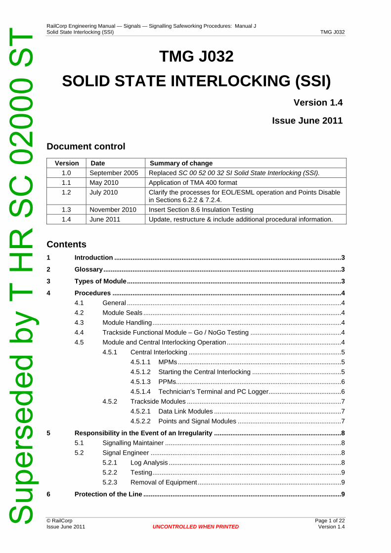
RailCorp Engineering Manual — Signals — Signalling Safeworking Procedures: Manual J Solid State Interlocking (SSI) TMG J032
© RailCorp Page 1 of 22 Issue June 2011 UNCONTROLLED WHEN PRINTED Version 1.4
TMG J032
SOLID STATE INTERLOCKING (SSI)
Version 1.4
Issue June 2011
Document control
Version Date Summary of change 1.0 September 2005 Replaced SC 00 52 00 32 SI Solid State Interlocking (SSI). 1.1 May 2010 Application of TMA 400 format 1.2 July 2010 Clarify the processes for EOL/ESML operation and Points Disable
in Sections 6.2.2 & 7.2.4. 1.3 November 2010 Insert Section 8.6 Insulation Testing 1.4 June 2011 Update, restructure & include additional procedural information.
Contents 1 Introduction .............................................................................................................................3 2 Glossary...................................................................................................................................3 3 Types of Module......................................................................................................................3 4 Procedures ..............................................................................................................................4
4.1 General ......................................................................................................................4 4.2 Module Seals .............................................................................................................4 4.3 Module Handling........................................................................................................4 4.4 Trackside Functional Module – Go / NoGo Testing ..................................................4 4.5 Module and Central Interlocking Operation...............................................................4
4.5.1 Central Interlocking ....................................................................................5 4.5.1.1 MPMs..........................................................................................5 4.5.1.2 Starting the Central Interlocking .................................................5 4.5.1.3 PPMs...........................................................................................6 4.5.1.4 Technician’s Terminal and PC Logger........................................6
4.5.2 Trackside Modules .....................................................................................7 4.5.2.1 Data Link Modules ......................................................................7 4.5.2.2 Points and Signal Modules .........................................................7
5 Responsibility in the Event of an Irregularity ......................................................................8 5.1 Signalling Maintainer .................................................................................................8 5.2 Signal Engineer .........................................................................................................8
5.2.1 Log Analysis ...............................................................................................8 5.2.2 Testing........................................................................................................9 5.2.3 Removal of Equipment ...............................................................................9
6 Protection of the Line .............................................................................................................9
Sup
erse
ded
by T
HR
SC
020
00 S
T

RailCorp Engineering Manual — Signals — Signalling Safeworking Procedures: Manual J Solid State Interlocking (SSI) TMG J032
© RailCorp Page 2 of 22 Issue June 2011 UNCONTROLLED WHEN PRINTED Version 1.4
6.1 Technician's Controls ................................................................................................9 6.2 Disconnections ........................................................................................................10
6.2.1 Disconnection of Signals..........................................................................10 6.2.2 Disconnection of Points............................................................................10
7 Failures...................................................................................................................................11 7.1 Interlocking Cubicle .................................................................................................12
7.1.1 Interlocking MPM......................................................................................12 7.1.1.1 Failure of one MPM...................................................................12 7.1.1.2 Failure of two or three MPMs....................................................12
7.1.2 Panel Processors .....................................................................................12 7.2 Points Modules ........................................................................................................13
7.2.1 Output Interface Failures..........................................................................13 7.2.2 Input Interface Failures.............................................................................13 7.2.3 Complete Module Failure .........................................................................13 7.2.4 Points Motor drive Output ........................................................................13 7.2.5 Slow Operation.........................................................................................13
7.3 Signal Modules ........................................................................................................14 7.3.1 Output Interface Failures..........................................................................14 7.3.2 Input interface Failures.............................................................................14 7.3.3 Complete Module Failure .........................................................................14
7.4 Data Link..................................................................................................................14 7.5 Technicians Terminal and PC Logger .....................................................................15 7.6 Reporting .................................................................................................................15 7.7 Track Circuits...........................................................................................................15 7.8 Faulting and Maintenance Manuals.........................................................................15
8 Maintenance ..........................................................................................................................15 8.1 Use of SSI Test Equipment .....................................................................................15
8.1.1 Data Link Telegram Generator.................................................................16 8.1.2 Data Link Interrogator...............................................................................16 8.1.3 Conventional test equipment....................................................................16
8.2 Power Supplies........................................................................................................16 8.2.1 Testing the Change-over Function...........................................................16 8.2.2 Maintenance By-Pass Switch...................................................................17
8.3 Rostered Maintenance Visits ...................................................................................17 8.3.1 Peripheral Equipment...............................................................................17 8.3.2 Technicians Terminal PC Logger.............................................................17 8.3.3 Data Link Line Measurements .................................................................17
8.4 Installed SSI Software Record.................................................................................17 8.5 Spares......................................................................................................................17 8.6 Insulation Testing.....................................................................................................18
Appendix A Forms......................................................................................................................19
Sup
erse
ded
by T
HR
SC
020
00 S
T

RailCorp Engineering Manual — Signals — Signalling Safeworking Procedures: Manual J Solid State Interlocking (SSI) TMG J032
© RailCorp Page 3 of 22 Issue June 2011 UNCONTROLLED WHEN PRINTED Version 1.4
1 Introduction SSI employs microelectronic technology to maintain the integrity of the railway signalling, and for the transmission of safety data to the line-side. Microprocessors and programmable devices are installed within the interlocking, and within points and signal modules which control ground signalling equipment. The software programs resident within these devices are fixed and protected. The overall system is of modular design: all modules are plug coupled, and first line fault rectification is limited to the exchange of modules.
SSI is made up of two main groups of equipment; the central interlocking that contains the main processing units and the trackside functional modules. The two groups of equipment are linked by a dedicated communications bearer enabling the interlocking to be located a great distance from the trackside modules it controls. This allows control of a large area from a central point where a number of interlockings are co-located.
SSI incorporates a system of automatic fault monitoring. Faults to line-side equipment, such as signal lamp failures and loss of point detection are detected by the diagnostic system and an appropriate fault message provided to the technician’s terminal and an audible alarm raised. SSI module failures are also detected and similarly reported. In addition a system logger is provided which records all messages sent to and from the interlocking. This log is available for analysis as required.
2 Glossary DLI Data Link Interrogator DLM Data Link Module DLTG Data Link Telegram Generator LDT Long Distance Terminal MM Memory Module MPM MultiProcessor Module NVRAM Non-Volatile Random Access Memory PM Points Module PPM Panel Processor Module SM Signal Module SSI Solid State Interlocking TFM Trackside Functional Module TT Technicians Terminal
3 Types of Module SSI utilises the following modules:
MultiProcessor Module MkII & MkIII Memory Module MkII & MkIII Panel Processor Module MkII Long Distance Terminal MkII Data Link Module MkII, MkIII & MkIIIA Signal Module MkII & MkIIIA Points Module MkII & MkIIIA
Sup
erse
ded
by T
HR
SC
020
00 S
T

RailCorp Engineering Manual — Signals — Signalling Safeworking Procedures: Manual J Solid State Interlocking (SSI) TMG J032
© RailCorp Page 4 of 22 Issue June 2011 UNCONTROLLED WHEN PRINTED Version 1.4
4 Procedures 4.1 General
The procedures given hereunder are those specific to SSI. They are supplementary to other procedures contained within this manual, which must be obeyed where relevant.
All SSI modules are fitted with 50 way or 75 way plug couplers fitted with coding pins. It is therefore not possible to connect the incorrect type of SSI module to the fixed wiring when exchanging modules. The connectors are secured by two hand operated retaining bolts and care must be exercised when removing/replacing these connectors to ensure that the bolts are unscrewed/screwed evenly or damage to the connector may result.
4.2 Module Seals
With the exception of memory modules, all other modules supplied by their manufacturers are factory sealed. These seals shall not under any circumstances be broken in the field by maintenance staff.
Memory modules are sealed by the Signal Design office or an accredited Design Office.
Modules with broken seals or no seal fitted on are not to be used. Non-sealed modules are to be reported to the Principal Engineer, Signals Assurance for investigation.
4.3 Module Handling
The integrity of SSI modules being placed into service is safety critical. All modules must be handled, transported and stored with care, and not in any manner, condition or circumstance that would subject them to damage or deterioration. SSI modules must be stored on racks in enclosed buildings or locations in a clean, dry non corrosive environment below 70°C.
Solid State Interlocking equipment contains electronic components that may be damaged by misuse. No SSI module is to be disconnected unless its power has been turned off first.
4.4 Trackside Functional Module – Go / NoGo Testing
A Go / NoGo Tester is provided to enable a PM or SM to be functionally tested before being installed, for example as a replacement for a failed module. The Go / NoGo Tester causes the contents of the TFM’s NVRAM to be updated. This sets the interlocking identity to zero, thus enabling modules taken from one interlocking to be re-installed in another.
Note: In the event of a signalling irregularity or an alleged signalling irregularity, the associated point or signal modules must not be tested using a TFM tester as this will erase the contents of the memory.
All modules shall be tested on the TFM Go / NoGo Tester before being put into operational use or being placed into the local spares holding.
4.5 Module and Central Interlocking Operation
When it is necessary to remove interlocking or diagnostic multi processor modules, or panel processor modules from the interlocking cubicle they shall be removed complete with their associated memory module, and replaced by new units which are also fitted with the appropriate memory module. Faulty or suspect MPMs and PPMs shall be promptly returned to the manufacturers, accompanied by the appropriate documentation
Sup
erse
ded
by T
HR
SC
020
00 S
T

RailCorp Engineering Manual — Signals — Signalling Safeworking Procedures: Manual J Solid State Interlocking (SSI) TMG J032
© RailCorp Page 5 of 22 Issue June 2011 UNCONTROLLED WHEN PRINTED Version 1.4
as detailed in Section 7.6, unless there is a need to retain the unit for further investigation.
Note: During major failure situations with limited spare programmed Memory Modules, it is permissible to re-use Memory Modules that were not in-service during the original failure.
4.5.1 Central Interlocking
4.5.1.1 MPMs
When a MPM needs to be changed from an operational interlocking, the following steps must be taken to ensure the entire interlocking is not shut down in error;
• The MPM to be changed is identified,
• Use the Technician’s Terminal to ‘disable’ the MPM via the Command Menu. This will force the interlocking into a “2 from 2” mode using the remaining MPMs to carry out the interlocking functions.
• Once the Technician’s Terminal message confirms the MPM is ‘disabled’. Turn off the MPM by using the power switch at the rear of the unit. The wiring plug couplers are then removed.
• Check the replacement MPM’s configuration to confirm MPM and MM comply with the hardware, fixed programs and site specific data requirements of the Installed SSI software record as per sections 8.4 before installation.
• Check that the seals are intact and the power switch is off.
• Install the replacement MPM. Connect the plug couplers. Turn on by the power switch on the rear of the unit.
• The MPM will then become operational without further intervention from the Signal Maintainer.
• Do not turn on any other MPM for at least one minute. This step only applies when turning on 2 or more MPMs to start an interlocking.
• Do not disable, turn off or remove any other MPM for at least 10 minutes.
4.5.1.2 Starting the Central Interlocking
If two or more replacement MPMs or MMs are installed or a prolonged shutdown has occurred then the Central Interlocking will have to be started from the Technician’s Terminal.
a) Replace the MPMs as per section 4.5.1.1.
b) List the Technician’s Controls and check them against the Technician’s Terminal Control Log Book.
c) Update and confirm that the Technician’s Controls are in accordance with the Technician’s Terminal Control Log Book.
d) Wait until the MPM’s have been running for at least 4 minutes so that the interlocking timeout has elapsed. During this period on a panel controlled system the panel indication for “normal working failed” will be FLASHING and for a VDU controlled system there will be an “interlocking timing out” alarm.
Sup
erse
ded
by T
HR
SC
020
00 S
T

RailCorp Engineering Manual — Signals — Signalling Safeworking Procedures: Manual J Solid State Interlocking (SSI) TMG J032
© RailCorp Page 6 of 22 Issue June 2011 UNCONTROLLED WHEN PRINTED Version 1.4
e) After this 4 minute timeout period on a panel controlled system the panel indication for “normal working failed” will be ON and for a VDU controlled system the “interlocking disable” alarm will be set.
f) Perform the “Start Interlocking” command. There will be a prompt to enter further technician’s controls or verify that there are no more to be added. Following this response the interlocking will commence its start-up process.
g) When normal operation is resumed the "normal working failed" indication on a panel controlled system will turn off and the “interlocking disabled” alarm will clear on a VDU controlled system.
h) For each set of points;
i) Arrange for the signaller to “key points” from the centre position to the last known position and return to the point key centre position to regain the ‘points free’ indication.
ii) Then, arrange for the signaller to “key points” from the centre position to the last known position and return to the point key centre position to regain point detection.
Note: Disabled points need to be managed in accordance with section 6.2.2.
4.5.1.3 PPMs
When a PPM needs to be changed from an operational interlocking, the following steps need to be taken;
• The PPM is turned off by the power switch at the rear of the PPM.
• Check the replacement PPM’s configuration in accordance with section 8.4 before being installed.
• Check the seals are intact and the power switch is off.
• Install the PPM and connect the plug coupler. Turn on the power switch at the rear of the unit.
• The PPM will then become operational without further intervention from the Signal Maintainer.
4.5.1.4 Technician’s Terminal and PC Logger
The Technician’s Terminal provides the facilities for the Signal Maintainer to access and control up to six SSI Central Interlockings. The Technician’s Terminal is connected to each Diagnostic MPM and this processes all fault and diagnostic information. Each Diagnostic MPM will send a message to the Technician’s Terminal for;
• the occurrence of a fault,
• the clearance of a fault,
• the occurrence and clearance of an intermittent fault.
Each fault has an alarm status that is repeated on the Signalman’s Control Panel;
• Critical. There will be an immediate effect on train movements,
• Non Critical. There will be no immediate effect on train movements but there will be intervention required before further system degradation occurs that could affect train movements.
Sup
erse
ded
by T
HR
SC
020
00 S
T
RailCorp Engineering Manual — Signals — Signalling Safeworking Procedures: Manual J Solid State Interlocking (SSI) TMG J032
© RailCorp Page 7 of 22 Issue June 2011 UNCONTROLLED WHEN PRINTED Version 1.4
Access to the facilities of the Technician’s Terminal is by password. The Maintenance Signal Engineer is responsible for the password and for changing it if this becomes necessary. Signal Maintainers may be requested to enter their name, location and purpose by the system.
The Technician’s Terminal can be remotely accessed by a PC in another location via a modem and telephone line to gain information on faults and to monitor system activity. This facility may be used before proceeding to site, or to assist in providing immediate advice to the attending Signalling Maintainer. During a remote access session, local terminal access is disabled and fault printer records the access details.
The technicians terminal fault printer generates records of all faults, all accesses to the Technician’s Terminal, controls applied and other associated information. The hard copy output from the printer shall be retained and held on site in the technicians terminal records file.
Generally hard copies are to be held for a minimum of 6 months. Records relating to incidents should be kept for 7 years.
The PC logger records;
• all changes of state of the SSI,
• all faults as they occur and are cleared,
• all Technician’s Controls as they are applied and removed.
This data can be downloaded and used to generate a log of operations of the SSI.
4.5.2 Trackside Modules
Before removing the plug coupler that attaches a trackside module to the fixed wiring, it must have its power removed as outlined in Sections 4.5.2.1 and 4.5.2.2.
When installing a trackside module the module retaining screws and plug coupler must be secured before restoring power.
4.5.2.1 Data Link Modules
When it is necessary to remove operational DLMs from a working system, care must be exercised to ensure that disruption to transmissions, with the loss of data by associated TFMs, does not occur. Under normal circumstances removal of any one DLM will have no effect on the operation of the signalling as the data link transmission system is duplicated. A DLM must be powered down by removing its BX supply fuse or NX disconnect pin.
Faulty or suspect DLMs shall be promptly returned to the manufacturers, accompanied by the appropriate documentation as detailed in Section 7.6 unless there is a need to retain the unit for further investigation.
4.5.2.2 Points and Signal Modules
When it is necessary to remove operational point or signal modules from a working installation they must first be powered down by removing the appropriate module 110V NX disconnect pin. All modules being placed into service shall have first been confirmed operational by being satisfactorily tested on the TFM Go / NoGo Tester referred to in Section 4.4.
There is a 9 to 12 second initialisation period before a module comes on line after the application of its 110V ac supply.
Sup
erse
ded
by T
HR
SC
020
00 S
T

RailCorp Engineering Manual — Signals — Signalling Safeworking Procedures: Manual J Solid State Interlocking (SSI) TMG J032
© RailCorp Page 8 of 22 Issue June 2011 UNCONTROLLED WHEN PRINTED Version 1.4
Points will not show detection status to the signaller when a Points Module (PM) is replaced or powered off and on. The signaller is to be contacted and requested to key the points to the last known position so that detection is restored when a PM is powered on.
If it becomes necessary to transfer point and signal modules from one SSI interlocking to another, these modules must, before re-installation, be tested on the TFM Go / NoGo Tester in order to erase their old interlocking identity number as detailed in Section 4.4.
Faulty or suspect modules shall be promptly returned to the manufacturers accompanied by the appropriate documentation as detailed in Section 7.6 unless there is a need to retain the unit for further investigation.
5 Responsibility in the Event of an Irregularity 5.1 Signalling Maintainer
The Signalling Maintainer's first duty is protection of the line in accordance with Procedure TMG J004 - Failures and Section 6 herein.
a) Incident reporting, inspections and examinations shall also be carried out in accordance with Procedure TMG J004 - Failures.
b) The Technician’s Terminal fault print out should be examined for evidence of equipment failure or malfunction.
Current system activity, particularly telegram data to and from the trackside, should be monitored using the facilities provided for this purpose on the Technician’s Terminal. All unexpected activity shall be recorded in the Technician’s Terminal Controls Log Record Book or another book provided for the purpose.
c) Evidence of system operation during the incident is recorded on the PC system logger. The Signalling Maintainer is solely responsible for ensuring that the logger is not touched or tampered with in any manner, prior to the arrival of the investigating Signal Engineer.
d) The indications displayed on all relevant SSI modules, both trackside and interlocking shall be recorded, along with their associated serial numbers. It may be necessary for these modules to be removed later for investigation.
5.2 Signal Engineer
5.2.1 Log Analysis
A Signal Engineer is responsible for investigating the incident in accordance with Procedure TMG J004 – Failures.
The Signal Engineer shall copy the relevant data message file from the SSI Technician’s Terminal PC system logger to floppy disk, and then, using the analysis program, analyse the data bits in the messages to check on what controls and indications were sent to and from the line-side during the time of the incident.
In the event of an irregularity being detected in the transmitted data messages then the site will be protected in accordance with Procedure TMG J004 - Failures. The Signal Engineer will determine whether the interlocking shall be stopped via the Technician’s Terminal. They shall examine the signalling control tables and data listings and give appropriate instructions for any further action to be taken.
The log analysis shall form part of the Incident Report.
Sup
erse
ded
by T
HR
SC
020
00 S
T

RailCorp Engineering Manual — Signals — Signalling Safeworking Procedures: Manual J Solid State Interlocking (SSI) TMG J032
© RailCorp Page 9 of 22 Issue June 2011 UNCONTROLLED WHEN PRINTED Version 1.4
5.2.2 Testing
The Technician’s Terminal may be used to test the conditions leading up to an incident by the application of track circuit occupancy via the Technician controls. The logger will be recording all system activity and can be later analysed and compared with the original incident log.
5.2.3 Removal of Equipment
SSI modules suspected of mal-operation shall be initially subjected to functional tests in situ. These tests shall simulate, as accurately as possible, the events leading to the irregularity, and module behaviour shall be observed and recorded. If the incident warrants, the module in question shall be removed and returned to the appropriate third line facility for a detailed examination. Full details shall be recorded of any module so removed.
TFM modules under investigation must not be placed in a TFM Go / NoGo tester as it can destroy the history of the module’s operation.
6 Protection of the Line 6.1 Technician's Controls
Facilities are provided within the SSI Technician's Terminal to allow the application and removal of restrictive controls to the interlocking. The following technician’s controls are provided from the Command Menu – option 6 from the Main Menu:
0 – Return to Main Menu
1 – Aspect disconnect
2 – Temporary approach control
3 – Track circuit occupy
4 – Route bar
5 – Points disable
6 – Start interlocking
7 – Stop interlocking
8 – Disable MPM
9 – Select interlocking
The application and removal of these controls must be done as per Section 6.2. All controls applied must be recorded on Technician’s Terminal Controls Log book.
A book of forms SF J032/B shall be used as the “Technician’s Terminal Controls Log”.
When a SSI has been stopped and switched off, then restarted, any Technician’s Controls that were applicable may have been lost. In this instance the Signalling Maintainer must check and reapply any Technician’s Controls that have been lost that are shown in the Technician’s Terminal Controls Log Record Book before starting the interlocking.
Facilities are also provided within the Technician's Terminal for the interlocking to be stopped or re-started for emergencies. The "Stop Interlocking" command will cause all signals to revert to stop, and route setting will no longer be possible.
Sup
erse
ded
by T
HR
SC
020
00 S
T

RailCorp Engineering Manual — Signals — Signalling Safeworking Procedures: Manual J Solid State Interlocking (SSI) TMG J032
© RailCorp Page 10 of 22 Issue June 2011 UNCONTROLLED WHEN PRINTED Version 1.4
6.2 Disconnections
When it is required to disconnect signalling apparatus, the necessary safe working procedures shall be strictly observed as stipulated in TMG J009 – Disconnection of Signalling Apparatus.
6.2.1 Disconnection of Signals
The following action should be taken in order to place any signal controlled by an SSI signal module to its most restrictive aspect. When it is required to disconnect a signal controlled from an SSI signal module in order to place it at stop and prevent it from clearing, the signal shall be at stop with no route set from it, then a ‘route bar’ shall be applied from the Technician's Terminal.
If the Technician's Terminal is not available then:
a) For a running signal with a trainstop, the signal train stop motor fuse shall be removed and the trainstop reverse indication into the module shall be opened at the external cable link. This places the trainstop and the signal at stop.
This method is also to be used if it is required to disconnect the trainstop itself or if authority is obtained to suppress the trainstop in failure conditions.
b) If trainstop control of the signal is not provided then the signal "A" track circuit shall be disconnected to force the signal to be retained at stop. It should be remembered that this may cause other signals to be returned to stop and associated points to be track locked.
c) If methods a) and b) are not practical, the signal module can be forced to adopt the "red retaining" mode of operation by removal and replacement of the link in the NX (current path) return from the signal head. On removal of the external cable link the module "output interface" indication will be extinguished. After a period of at least 5 seconds the link should be re-inserted and confirmation obtained that a red aspect is displayed.
Fuses to the signal's aspects other than red shall then be removed.
To return the signal module to normal operation it is necessary to power down the module and then power up. All functions provided by the module will obviously be lost whilst the power is off.
Note: It must be appreciated that a main power supply interruption will also re-initialise the module and thus reinstate its output interface removing the "red retaining" feature. In this event if the signal is then cleared, the red lights will extinguish and the signal will be blacked out.
6.2.2 Disconnection of Points
When it is necessary to electrically disconnect a set of points controlled from an SSI points module in order to prevent their operation, then in addition to the requirements prescribed in TMG J009 - Disconnection of Signalling Apparatus, it is preferable that the points shall also be disabled via the Technician’s Terminal as described herein, after communicating with the Signaller.
To ‘book out’ a set of points normal, a points disable normal technicians control is used. A points disable reverse technician’s control is used to ‘book out’ a set of points reverse.
Sup
erse
ded
by T
HR
SC
020
00 S
T

RailCorp Engineering Manual — Signals — Signalling Safeworking Procedures: Manual J Solid State Interlocking (SSI) TMG J032
© RailCorp Page 11 of 22 Issue June 2011 UNCONTROLLED WHEN PRINTED Version 1.4
When technician’s controls for points disable normal are applied, the points identity number is used and the following is applicable;
• if the set of points are lying in the normal position they will remain in the normal position and be disabled from moving from the normal position until the points disable command is removed, or
• if the set of points are lying in the reverse position they will remain in the reverse position until such times as they are driven normal by either the signaller or a route call. Once the set of points are lying in the normal position they will remain in the normal position and be disabled from moving from the normal position until the disable command is removed.
The same philosophy is applicable to disabling in the reverse position. The number 64 is added to the points identity number to disable the points in the reverse position.
Note: The action of disabling points may result in the loss of detection in the event of a power failure at the controlling point module. The following joint intervention will be required by the Signalling Maintainer and the Signaller to restore the points detection and the disable control. The Signal Maintainer must remove the disable control from the points, then the Signaller must remove their block on the points key and centre the points control key, then restore it to the same position as the points are lying to restore point detection. The Signaller must then reapply their block on the points key and the Signal Maintainer must then reapply the points disable command.
Where ESML arrangements (Emergency Switch Machine Lock, Annett Key and attached crank handle) on electric points machines or EOL or plug connector arrangements on E.P. points machines are provided for the manual operation of power worked points, the disconnection of the points and the protecting signals is accomplished through use of ESML, EOL or plug connector arrangements.
When the ESML, EOL or plug connector arrangements are utilised during failure conditions or for the testing (only) of facing point locks and detectors, then it will not be necessary to disable the points from the Technician's Terminal.
ESML, EOL or plug connector arrangements are not to be restored while trains are approaching or moving over the points.
Following ESML or EOL operation, the points control will need to be operated from the control panel to correspond with the points position in order to re-establish the detection and control. The points control may then be reinstated to the centre position.
Note: In the case where there is loss of detection only, the points module will attempt to re-drive the points to the last controlled position. This operation is limited by a time-out feature of approximately 8-9 seconds.
7 Failures The SSI System maintenance and fault finding manual contains the detailed procedures for dealing with faults to the SSI system and equipment. The information given in this section outlines the module failure modes and key actions required.
It is not desirable to install a spare of an older type to effect repairs, but permissible where no suitable spares are available. In these instances the module installed is to be tagged for replacement with a correct type of module as soon as is practical.
Sup
erse
ded
by T
HR
SC
020
00 S
T

RailCorp Engineering Manual — Signals — Signalling Safeworking Procedures: Manual J Solid State Interlocking (SSI) TMG J032
© RailCorp Page 12 of 22 Issue June 2011 UNCONTROLLED WHEN PRINTED Version 1.4
7.1 Interlocking Cubicle
The SSI System cubicle incorporates duplicated panel processor modules and triplicated interlocking multi-processor modules. One PPM failure and/or one interlocking MPM failure will therefore have no effect on the operation of the signalling.
The Diagnostic MPM is not duplicated and failure of this module results in loss of all diagnostics and technicians terminal facilities.
7.1.1 Interlocking MPM
Where a MPM is to be replaced it is imperative that the status of the MM is checked before powering on the MPM. The MMs in use MUST have the same date, version etc as detailed on the software record located on the inside of the rear door of the interlocking cubicle. If this does not occur a MPM with the incorrect MM may have its safety fuse blown, or, possibly shut down the entire interlocking.
7.1.1.1 Failure of one MPM
Failure of one MPM has no operational effect on the interlocking. This will be indicated to the signaller by a non-critical alarm and the Signal Maintainer will receive an error message on the technician’s terminal printout.
The interlocking will operate in “2 from 2” mode, meaning there must be correlation between the two remaining MPMs at all times. This situation will persist until a serviceable module is installed in place of the faulty equipment.
Section 4.5.1.1 details the replacement procedure. “2 from 3” mode of operation will then be resumed.
7.1.1.2 Failure of two or three MPMs
Failure of two or more MPMs results in a total shut-down of the interlocking. This may be indicated to the signaller by a critical alarm with all panel indications frozen.
All signals will revert to stop.
This failure will persist until the faulty MPMs have been replaced. Section 4.5.1.1 details the procedure.
The Central Interlocking will then need to be started. Section 4.5.1.2 details the procedure.
7.1.2 Panel Processors
Failure of a single PPM will have no operational effect and result in a non-critical alarm to the signaller. However in exceptional cases a single faulty PPM can result in the loss of the Technician’s controls functionality.
Failure of both PPMs will result in loss of communication between the signalling control panel and the interlocking.
All panel indications will be extinguished and this failure will be indicated by an audible and visual alarm on the signaller's panel. The interlocking will continue to function normally with routes that are already set remaining so with signals cleared as appropriate, and trains will be moving in response to the signalling. It will not be possible to set any further routes.
These failures will persist until a serviceable PPM is installed with correct MM in place of the faulty equipment.
Sup
erse
ded
by T
HR
SC
020
00 S
T
RailCorp Engineering Manual — Signals — Signalling Safeworking Procedures: Manual J Solid State Interlocking (SSI) TMG J032
© RailCorp Page 13 of 22 Issue June 2011 UNCONTROLLED WHEN PRINTED Version 1.4
7.2 Points Modules
Failure of point equipment connected to the module such as loss of detection, or failure to drive are detected by the diagnostic system and alarmed via the Technician’s Terminal. Failures to points module themselves are also diagnosed and fall into 5 categories:
7.2.1 Output Interface Failures
Points modules can control two sets of points, known as X and Y and will disable outputs to either of these in the event of a fault occurring. A critical alarm will be given to the Signaller and the Technician’s Terminal will report "Points Module nn output interface". The points concerned will continue to be detected, but it will not be possible to move them from the signaller's panel.
This failure will persist until the points module is powered down and rebooted.
7.2.2 Input Interface Failures
All inputs, both point detection and general purpose are detected by a duplicated processor system within the module. If the processors disagree on the state of an input then an input interface fault is declared and the input concerned is set to its most restrictive state. A critical alarm will be given to the signaller and the Technician’s Terminal will report "Points Module nn input interface".
This failure will persist until the points module is powered down and rebooted. The Signal Maintainer should check the external circuits connecting to the points module for high resistance or bouncing contacts as these can cause this type of fault.
7.2.3 Complete Module Failure
In the event of a complete module failure, known as a "shutdown" a critical alarm will be given to the signalman and the Technician’s Terminal will report "no reply from TFM nn both links". The points will remain locked in their last set position, the interlocking will have lost detection and this will indicate to the signaller in the usual way. If a module fails to receive data on both data links A & B it will cease all transmissions. This is detected by the interlocking as the same as a module shutdown.
When the interlocking detects a module shutdown condition it immediately puts all input functions associated with that module to their most restrictive state, and retains this state until normal communications with the affected module are resumed.
This failure will persist until failed module is powered down and replaced by a new module.
7.2.4 Points Motor drive Output
The points module motor drive outputs failure modes include permanently ON and permanently OFF as they are not safety critical outputs. If a motor drive output fails in the permanently ON state then a fault message will appear on the Technicians Terminal and the ESMLR will remain energised. Loss of points detection will occur due to the back proving of the detection circuit through of the ESMLR down.
This fault will persist until the points module is changed.
7.2.5 Slow Operation
Slow points detection can occur due to back proving of the points control relays in the detection circuit. In this case points detection will only be achieved after the points module 8 second time out for motor control has elapsed.
Sup
erse
ded
by T
HR
SC
020
00 S
T

RailCorp Engineering Manual — Signals — Signalling Safeworking Procedures: Manual J Solid State Interlocking (SSI) TMG J032
© RailCorp Page 14 of 22 Issue June 2011 UNCONTROLLED WHEN PRINTED Version 1.4
7.3 Signal Modules
Failure of signalling equipment connected to the module, such as lamp failures, are detected by the diagnostic system and alarmed via the Technician’s Terminal. Failures to signal modules themselves are also diagnosed and fall into three categories:
7.3.1 Output Interface Failures
In the event of a fault occurring in the signal module output circuitry the module will disable its outputs and apply a "red retaining" feed to selected outputs, generally the red lamp(s) of its associated signals. A critical alarm will be given to the signaller and the Technician’s Terminal will report "Signal Module nn output interface". Current proving, and other inputs, will continue to be transmitted to the interlocking, but it will not be possible to clear the signal from the signaller's panel.
This failure will persist until the signal module is powered down and rebooted. The Signal Maintainer should check the external circuits to ensure that there is no voltage showing on outputs that are de-energised, and that there are no high resistance connections in the current sensing leg of any external circuits.
7.3.2 Input interface Failures
All inputs are detected by a duplicated processor system within the module. If the processors disagree on the state of an input then an input interface fault is declared and the input concerned is set to its most restrictive state. A critical alarm will be given to the signaller and the Technician’s Terminal will report "Signal Module nn input interface".
This failure will persist until the signal module is powered down and rebooted. The Signal Maintainer should check the external circuits connecting to the signal module for high resistance or bouncing contacts as these can cause this type of fault.
7.3.3 Complete Module Failure
In the event of a complete module failure, known as a "shutdown" a critical alarm will be given to the signaller and Technician’s Terminal will report "No reply from TFM nn both links". Any signal controlled by the failed module will be displaying a red (or most restrictive) aspect.
If a module fails to receive data on both data links A and B, it will cease all transmissions. This is detected by the interlocking as the same as a module shutdown. When the interlocking detects a module shutdown condition it immediately puts all input functions associated with that module to their most restrictive state and retains this state until normal communications with the affected module are resumed.
This failure will persist until failed module is powered down and replaced by a new module.
7.4 Data Link
Data link modules interface between the interlocking and the points and signal modules. The data link transmission system is duplicated, and under normal circumstances a failure to either link A or link B will have no effect on system operation, but will be detected by the diagnostics and a non critical alarm will be given to the signaller.
In some cases an intermittent fault on one data link can affect system operation if the other data link is disturbed. If a data link becomes unstable it may be necessary to turn it off by powering down the appropriate DLM at the central interlocking. Then find and repair the fault in the data link before restoring it to service.
Sup
erse
ded
by T
HR
SC
020
00 S
T
RailCorp Engineering Manual — Signals — Signalling Safeworking Procedures: Manual J Solid State Interlocking (SSI) TMG J032
© RailCorp Page 15 of 22 Issue June 2011 UNCONTROLLED WHEN PRINTED Version 1.4
Failures due to data link cable faults or data link bearer systems are also diagnosed and alarmed, and a printout is available to the technician indicating the position of the fault.
Failure of both data links results in the interlocking losing communications with all or some of its points and signal modules. Such failures are potentially serious and could cause the interlocking to be completely inoperative.
Diverse routes are generally adopted for the two transmission systems and thus complete failure to both links simultaneously is very rare.
Lightning protection is provided by surge protection units. These are installed at every location containing data link modules. Failure of these units is likely to affect many locations attached to the same data link.
7.5 Technicians Terminal and PC Logger
Should the technician’s terminal and / or the PC Logger fail the interlocking will continue to operate normally and the Signaller will receive a critical alarm. In this scenario the interlocking will not be able to be stopped or have any further Technician’s controls applied to, or removed from it. The logging function will also cease and the fault list in the buffer will be lost.
The PC logger functionality is critical for incident investigations. Failures of the PC logger must be dealt with promptly.
7.6 Reporting General failure reporting requirements are detailed in Procedure TMG J004 – Failures.
In addition a Solid State Interlocking Equipment Failure Report must be completed with the appropriate information associated for each failure at an SSI installation. This form shall be signed and attached to the associated Failure Report Form, and a copy attached to the faulty SSI module.
7.7 Track Circuits
SSIs do not allow for conventional methods to manually release route holding or approach locking. Track circuit failures will need to be rectified and affected traffic operated under the rules and regulations.
7.8 Faulting and Maintenance Manuals
Documents are provided which specify the detailed procedures for fault finding and maintenance. These documents shall be referred to as required.
8 Maintenance 8.1 Use of SSI Test Equipment
Test equipment specifically designed for SSI use is provided, and shall be operated in accordance with the manufacturers instructions.
Unauthorised development or use of other special diagnostic or test equipment is forbidden.
The types of test equipment provided are detailed in the following subsections;
Sup
erse
ded
by T
HR
SC
020
00 S
T

RailCorp Engineering Manual — Signals — Signalling Safeworking Procedures: Manual J Solid State Interlocking (SSI) TMG J032
© RailCorp Page 16 of 22 Issue June 2011 UNCONTROLLED WHEN PRINTED Version 1.4
8.1.1 Data Link Telegram Generator
This portable test unit simulates data link transmission from an interlocking and is designed for testing TFMs installed in locations before an installation is commissioned.
Data Link Telegram Generators are only to be issued for use of Signal Engineers authorised by Principal Engineer Signal Design.
Use of this equipment on working installations is strictly forbidden.
Unauthorised use could cause unsafe behaviour of the interlocking. It is critical that DLTG units are stored securely away from working installations and are only issued for use to suitably accredited Signal Engineers.
8.1.2 Data Link Interrogator
This portable test unit which is receive only, is used to monitor data link messages sent to or from the interlocking. It is attached to special test points provided in each location or bungalow where TFMs and DLMs are installed. DLIs are provided to Signalling Maintainers to assist in first line maintenance. Some DLIs also provide an output to trigger an oscilloscope when used in observing messages on the data link during second line maintenance. This enables only data from specific modules to be analysed from the constant stream of data passing between the interlocking and TFMs.
8.1.3 Conventional test equipment
Low input impedance test equipment could bypass input circuits for points and signal modules during testing. That is, the test equipment could be used to ‘bridge’ an input, resulting in a less restrictive input and therefore potentially an unsafe output.
Therefore:
• Digital MultiMeters (DMM) with an input impedance of less than 100kΩ shall NOT be used with SSI equipment.
• Fluke 114, 116, 117 and 289 DMMs have a LoZ (low AC impedance) mode for voltage measurements. This setting is NOT to be used in fault finding on SSI inputs.
• 20kΩ shunts must NOT be used on DMMs when fault finding on SSI inputs.
Sometimes Digital Storage Oscilloscopes are required to carry out conventional measurements. Mains powered and mains earthed oscilloscopes can be used providing that they have floating isolated input channels. Oscilloscopes that do not have floating, isolated input channels must not be directly connected to a data link as this will earth one leg and could cause the data link to fail.
8.2 Power Supplies
All SSI equipment operates from the signalling 120V ac supply. Normal and emergency primary supplies are provided, with automatic change-over controlled by a static switch, mechanical ECO or GGI (inverter).
8.2.1 Testing the Change-over Function
Correct operation of the static switch or GGI shall be tested on every maintenance visit and at least every 12 weeks by failing the normal supply and observing that the load is taken by the emergency supply with no effect on the SSI or associated signalling equipment. On restoration of the normal supply the static switch will automatically change back to this supply. A record of all such tests shall be maintained. The
Sup
erse
ded
by T
HR
SC
020
00 S
T

RailCorp Engineering Manual — Signals — Signalling Safeworking Procedures: Manual J Solid State Interlocking (SSI) TMG J032
© RailCorp Page 17 of 22 Issue June 2011 UNCONTROLLED WHEN PRINTED Version 1.4
mechanical block contactor on the normal supply input to the static switch or GGI must be inspected to confirm that the contactor de-energises when the normal supply is failed.
8.2.2 Maintenance By-Pass Switch
The static switch and GGI have a three position switch fitted to the unit to allow maintenance whilst the load is being directly supplied from either of the two sources. This should be left in the ‘auto’ position for the GGI and the ‘normal’ position for the static switch.
8.3 Rostered Maintenance Visits
Solid state interlocking equipment consists of a number of sealed modules requiring no maintenance and therefore routine maintenance in SSI areas will continue to be dominated by conventional signalling equipment.
8.3.1 Peripheral Equipment
The SSI Technician’s Terminal incorporates peripheral equipment such as printers, PC Logger and remote dial in modems which require maintenance in accordance with the manufacturer's recommendations. The Maintenance Signal Engineer shall program maintenance accordingly.
8.3.2 Technicians Terminal PC Logger
In order to prove that the logging feature is working correctly, the logging dialog is inspected to confirm correct time, date and log file updates have occurred. This test shall be carried out in accordance with the TMP.
8.3.3 Data Link Line Measurements
The SSI diagnostic system is designed to raise alarms when significant faults in the data link occur. However it is useful to check line levels as this will enable deterioration in the transmission line, or data link modules to be detected at an earlier stage and it will provide records on which to base future judgements on the line.
Line measurements should be taken and recorded. Generally this is done at the control centre, using a digital storage oscilloscope, with a data link interrogator providing the trigger source. Full details of the procedures for line measurements are given in the appropriate manuals.
The event logs shall be checked to confirm that no telegrams are being lost on either data link.
8.4 Installed SSI Software Record
Each SSI Central Interlocking has an ‘Installed SSI Software Record’ which details compatible hardware type and version as well as fixed program and site specific data identification.
The site copy is securely attached to the inside of each central interlocking cubicle rear door. The Installed SSI Software Record is provided and maintained by Signal Design.
8.5 Spares
It is important to ensure that any spare module provided is of the correct type for the system. Full details of module types and compatibilities are included in the installed software records referred to in section 8.4.
Sup
erse
ded
by T
HR
SC
020
00 S
T

RailCorp Engineering Manual — Signals — Signalling Safeworking Procedures: Manual J Solid State Interlocking (SSI) TMG J032
© RailCorp Page 18 of 22 Issue June 2011 UNCONTROLLED WHEN PRINTED Version 1.4
All spare modules shall be tested and stored in accordance with Section 4.4.
The following should be used as a guide when selecting an appropriate SSI module to replace a failed unit;
• MPM. Use the same brand, type (MkII or MkIII), Mod State (Ver). This is critical where internal data links are used.
• MM. Ensure the same type and configuration as per the installed system records.
• PPM. The preference is for the same brand. They are all MkII
• DLM. The preference is for the same brand. They are all interchangeable.
• LDT. There is only one type currently approved for use.
• SM. They must be the same brand and it is desirable for the same type (MkII or MkIIIA). It is permissible to upgrade from a MkII to a MkIIIA, unless the particular TFM is labelled as ‘MkII only’.
• PM. They must be the same brand and it is desirable for the same type (MkII or MkIIIA). It is permissible to upgrade from a MkII to a MkIIIA.
Note: DLMs, signal and points modules are moving towards higher types, MkII to MkIII etc., due to improved reliability.
The numbers of spare SSI equipment held is a logistics issue and will be determined by the local Signal Maintenance Engineer.
8.6 Insulation Testing
SSI equipment is not to be insulation tested.
Insulation testing is only undertaken on fixed wiring in a location or wiring to trackside apparatus. The SSI equipment is to be powered off and disconnected from the fixed wiring prior to insulation testing taking place.
Refer to TMG J023 - Insulation Inspection and Testing for more detailed information and exemptions to testing requirements.
Sup
erse
ded
by T
HR
SC
020
00 S
T

RailCorp Engineering Manual — Signals — Signalling Safeworking Procedures: Manual J Solid State Interlocking (SSI) TMG J032
© RailCorp Page 19 of 22 Issue June 2011 UNCONTROLLED WHEN PRINTED Version 1.4
Appendix A Forms RailCorp Signalling Form SF J032/A Sh.1 of 2 Rev.1
S S I E Q U I P M E N T F A I L U R E R E P O R T Report No.: District: Control Centre : What Interlocking is equipment connected to: Please complete all relevant sections by ticking appropriate boxes and answering appropriate questions. Append one copy to any failed equipment returned to the manufacturer and forward another copy and append to the Failure Report Form. 1. TIME Time of Failure: Date of Failure: Tech. Terminal Fault Printout: 2. DESCRIPTION (INTERNAL EQUIPMENT) (Tick the appropriate box) What piece of equipment failed:
Panel Processor Module Multi Processor Module Diagnostic Processor Module Other (Specify) 3. DESCRIPTION (EXTERNAL EQUIPMENT) What piece of equipment failed: Signal Module At what system address: Manufacturer: What type(s) of Signal does the module drive : Which indications were alight on arrival at site:
Power System Rx Data Outputs Points Module At what system address: Manufacturer: What type(s) of Points does the module drive :
Air Points or what type of point machine : Which indications were alight on arrival at site:
Power System Rx Data Points X Points Y
Sup
erse
ded
by T
HR
SC
020
00 S
T

RailCorp Engineering Manual — Signals — Signalling Safeworking Procedures: Manual J Solid State Interlocking (SSI) TMG J032
© RailCorp Page 20 of 22 Issue June 2011 1.4 UNCONTROLLED WHEN PRINTED Version
RailCorp Signalling Form SF J032/A Sh.1 of 2 Rev.1
S S I E Q U I P M E N T F A I L U R E R E P O R T Data Link Module At which location: Which Data Link (A or B) Manufacturer: Long Distance Terminal At which location: Which Data Link (A or B) Manufacturer: What indications were alight on arrival at sight:
System Data from SSI Data to SSI Data to PCM
PCM Tx Clock PCM Rx Clock PCM Rx Line Power 4. HOW WAS THE FAULT RESTORED ?
Module recovered on its own: Module recovered after being powered down then up: Module replaced with the spare, serial numbers below Failed Module Serial No.: Replacement Module Serial No: 5. OTHER INFORMATION
DC Electrified Area: YES NO Weather conditions at time of failure(e.g. dry, wet, hot, lightning): Other comments(e.g. power failure or interruption etc.): Signed: Date: / /
Sup
erse
ded
by T
HR
SC
020
00 S
T

RailCorp Engineering Manual — Signals — Signalling Safeworking Procedures: Manual J Solid State Interlocking (SSI) TMG J032
© RailCorp Page 21 of 22 Issue June 2011 Version 1.4 UNCONTROLLED WHEN PRINTED
RailCorp Signalling Form SF J032/B Rev.1
TECHNICIAN TERMINAL CONTROLS LOG
Control Centre :
Interlocking Name:
TIME & DATE CONTROL APPLIED BY WHOM REASON FOR
CONTROL CONTROL REMOVED BY WHOM TIME & DATE
Sup
erse
ded
by T
HR
SC
020
00 S
T

This page has been intentionally left blank
UNCONTROLLED WHEN PRINTED Page 22 of 22 Sup
erse
ded
by T
HR
SC
020
00 S
T

RailCorp Engineering Manual — Signals — Signalling Safeworking Procedures: Manual J Electric Train Staff Instruments TMG J033
© RailCorp Page 1 of 12 Issued May 2010 UNCONTROLLED WHEN PRINTED Version 1.1
TMG J033
ELECTRIC TRAIN STAFF INSTRUMENTS
Version 1.1
Issued May 2010
Document control
Version Date Summary of change 1.0 September 2005 Replaced SC 00 52 00 33 SI Electric Train Staff Instruments. 1.1 May 2010 Application of TMA 400 format
Contents 1 Introduction .............................................................................................................................2 2 Servicing of Staff Instrument.................................................................................................2 3 Special Requirements.............................................................................................................4
3.1 Intermediate Instrument.............................................................................................4 3.2 Automatic Switch Boxes ............................................................................................4 3.3 Isolating Relays .........................................................................................................4
4 Signal Engineer’s Tests..........................................................................................................5 4.1 District Audit...............................................................................................................5
5 Lost Staff..................................................................................................................................5 6 Damaged Staff .........................................................................................................................7 7 Staff Balancing by Signalling Maintainers ...........................................................................8
7.1 Balancing at Intermediate Instruments ......................................................................9 7.2 General Requirements...............................................................................................9
8 Changing of Staff Instruments ............................................................................................10 Appendix A Forms......................................................................................................................11
Sup
erse
ded
by T
HR
SC
020
00 S
T
RailCorp Engineering Manual — Signals — Signalling Safeworking Procedures: Manual J Electric Train Staff Instruments TMG J033
© RailCorp Page 2 of 12 Issued May 2010 UNCONTROLLED WHEN PRINTED Version 1.1
1 Introduction Prior to commencing work on the staff instruments the Signalling Maintainer shall advise and obtain the concurrence of the Signallers at both ends of the section (or, if unattended, the Train Controller) of the work to be carried out and ensure that the switchbox, if provided, is in ordinary working.
The testing signal (3-5-3) shall be transmitted on the bell and acknowledged in accordance with the procedures.
A full understanding of the work to be carried out shall be reached by all parties concerned.
When working on intermediate staff instruments the four line wires shall then be disconnected by opening the links provided at the terminals and not re-connected until the work/examination is complete. When the line wires have been re-connected the instruments shall be tested.
The Signalling Maintainer shall not remove or place a staff in the staff instrument in connection with the working of trains. The suitably accredited Signalling Maintainer shall not inadvertently give permission to the signaller at the opposite end of the section to withdraw a staff by holding down on the bell key.
Staff instruments shall never be left open or any staffs left out during the absence of the Signalling Maintainer. Therefore, if the Signalling Maintainer has cause to leave the instrument while engaged in examining or cleaning it, s/he shall replace all the staffs in the instrument and lock the instrument.
Should a train arrive at a station before the Signalling Maintainer has completed the work, and the instrument is not ready to receive the incoming staff, the signaller (if in attendance) shall retain possession of the staff until the instrument is ready to receive it. The work shall be completed as quickly as possible so that the staff can be replaced in the instrument.
A staff shall not be withdrawn for a train until the work has been completed and the instruments have been tested.
The Maintenance Signal Engineer shall keep a register with updated, accurate details of all staff instruments, staffs, key staffs, staff exchangers, automatic switch boxes, etc on the maintenance area.
2 Servicing of Staff Instrument On each rostered maintenance visit the following service procedure shall be carried out:
a) Immediately on opening the instrument the position of the cam shall be noted and recorded in relation to the number of staffs in the instrument. On completion of maintenance the position of the cam shall be checked again in relation to the number of staffs in the instrument.
b) Remove the top spindle and clean and oil. Thoroughly clean all lock components and inspect locking faces for wear.
Sup
erse
ded
by T
HR
SC
020
00 S
T

RailCorp Engineering Manual — Signals — Signalling Safeworking Procedures: Manual J Electric Train Staff Instruments TMG J033
© RailCorp Page 3 of 12 Issued May 2010 UNCONTROLLED WHEN PRINTED Version 1.1
Only clock oil shall be used on the instrument. The oiling of spindles and bearings shall be carried out by using a clean oily rag sparingly. Under no
circumstances is an oil can to be used. It is vital that oil is not allowed to reach the fluted faces of magnetic locks.
c) Rotate the drum and inspect for rust, accumulation of dust, or any stiffness of operation. Wipe the top surfaces of the drum clean.
In the event of any heavy rusting or stiffness in operation remove the drum, clean off the rust, and lightly oil spindle.
Whenever the drum is removed the opportunity shall be taken to thoroughly clean the inside of the instrument and inspect, clean and oil the back locks and springs where provided.
d) Check the magnetic lock for residual magnetism. Check that the magnetic lock does not stick due to oil or foreign matter on the pole faces. Check the fluted brass faces to ensure that they are securely fastened to the armature ie. riveted and soldered. Clean the flutes and faces carefully.
It is vital that no oil is allowed on these faces.
e) When replacing the spindles they must be carefully rotated into place. Do not bump them with the hand of any other object when replacing. Tighten the retaining screws of the top spindle to prevent it from moving or turning.
f) Remove the five contact fingers one at a time and clean the bearing pin. Examine each contact for signs of fracture and loss of tension. Check that the clearance between make and break is ample. (Note where an automatic switchbox is in use at the other end of the section 1mm overlap, (make before break), is provided on number two (2) contact).
g) Test the condition of all cells in the local, line, and the bell batteries.
h) Check all screws and nuts for tightness (except for bottom locks which shall be checked on 12 monthly service and each time that the drum is removed).
i) Examine the gauge block or gauge plate and test with staffs from adjoining sections.
(See also twelve monthly service for gauge block or gauge plate).
j) Check that the insulated extension piece opens the index switch where staff is withdrawn. The contact shall break as soon as (but not before) the drum has rotated sufficiently for the lock to clear the index in the drum.
k) At intermediate instruments details of the currents through both coils shall be recorded on a Staff Instrument Record Card (kept in the terminal box).
l) Test the operation of the electric lock with no current through the line coils by attempting to withdraw a staff and also manually to ensure that there is no tendency for the lock to lift. Check that the safety lever locks the ringing key, as it starts to lift and throughout the whole of its travel also, and that the electric lock is locked by the safety lever when the bell key is depressed, ie. before number three (3) contact makes.
m) Test and record the line and local coil currents on the staff instrument record card. Whenever possible, these tests shall be made with both ends in ordinary
Sup
erse
ded
by T
HR
SC
020
00 S
T
RailCorp Engineering Manual — Signals — Signalling Safeworking Procedures: Manual J Electric Train Staff Instruments TMG J033
© RailCorp Page 4 of 12 Issued May 2010 UNCONTROLLED WHEN PRINTED Version 1.1
working, when this is not possible a note shall be made on the record card. When a new Staff Instrument Record Card has been compiled, the old card shall also be retained so that a minimum of 12 months record is kept. The record cards shall be kept in the battery cupboard which shall be kept locked and sealed at all times.
n) Examine all staffs to ensure that rings are not loose or broken and the inscriptions and numbers are clear and legible.
o) Examine staff transfer magazines to check that they engage the attachments on the instruments and that the keys and locks function correctly. Examine instruments to check that a staff cannot be withdrawn between the separators of the column or from the space between the top of the separators and the head of the instrument.
The screws holding the faceplates on the instrument and transfer magazine locks shall be checked for tightness. At least two of these screws are recessed and must be sealed with a lead plug to avoid unauthorised interference. The box provided for the transport of the magazine shall be examined to ensure it is in good order and is legibly inscribed. A certificate shall be forwarded to Maintenance Signal Engineer every six months in January and July stating that the transfer magazines and instruments have been examined and are in order.
p) With the instrument closed and a staff withdrawn test the instrument to ensure that a second staff cannot be obtained.
3 Special Requirements When carrying out maintenance services to the TMP and Service schedules the following shall apply:
3.1 Intermediate Instrument
Prior to commencing any work on an intermediate instrument the signallers at both ends of the section shall be notified. When the signallers have been notified, the four line wires shall be disconnected by opening the links at the line termination terminals which are situated in the cupboard adjacent to and separate from the staff instrument and left opened until the work is complete. When the links at the line termination terminals have been closed the instruments shall be tested to ensure the correct phase relationship of the whole of the instruments concerned.
3.2 Automatic Switch Boxes
When maintaining the automatic switch box the operation of the time delay mechanism shall be checked. In the case of a relay type switch box ensure that the 'A' relay does not hold in due to residual magnetism. The air gap between the pole face and the armature is to be approximately 0.05mm which is equivalent to the thickness of ordinary writing paper.
3.3 Isolating Relays
Isolating relays are used on miniature electric train staff sections where the line voltage is in excess of 70 Volts or 46 cells are used. Isolating relays shall be tested as frequently as possible to ensure that satisfactory contact conditions are being maintained. Isolating relays are provided to eliminate the possibility with high voltage DC circuits of a staff instrument contact, on opening, drawing and sustaining an arc.
Sup
erse
ded
by T
HR
SC
020
00 S
T

RailCorp Engineering Manual — Signals — Signalling Safeworking Procedures: Manual J Electric Train Staff Instruments TMG J033
© RailCorp Page 5 of 12 Issued May 2010 UNCONTROLLED WHEN PRINTED Version 1.1
4 Signal Engineer’s Tests After the completion of the twelve monthly service work on every second year in the presence of the Maintenance Signal Engineer the instrument shall be tested as follows:-
Test 1 A working test of line and local coils at failing currents shall be carried out using an adjustable resistor(rheostat). The failing current line coil is 90ma and for the local coil is 95ma.
Test 2 When the circuit does not have an isolating relay, the local line battery at the station being tested, shall be connected across the line coil with the local coil disconnected, and an observation made that the lock does not lift, while lifting a staff into the head of the instrument.
Test 3 Test that the line coil incoming current does not allow the lock to lift, while lifting a staff to the head of the instrument, while the local coil is disconnected.
Test 4 Test that the local coil normal battery current does not enable the lock to lift while lifting a staff to the head of the instrument, while the line coil is disconnected.
Line Coil 115mA Minimum 130mA Maximum
Local Coil 110mA Minimum 125mA Maximum
All readings shall be recorded on the Staff Instrument Record Card. A minimum of twelve months record shall be kept. The record card shall be kept in the battery cupboard. The lock of the cupboard shall be sealed with a cupboard seal.
4.1 District Audit
The Maintenance Signal Engineer shall conduct an annual audit of the number of train staffs and their respective numbers on each Electric Train Staff section on the district.
If the audit does not agree with that shown on the Staff Instrument number plate the Maintenance Signal Engineer is to notify the Principal Engineer Signals Assurance and the Network control representative for the area.
5 Lost Staff When a staff is lost the provisions of Network Rule NSY 504 are to be followed. The train Controller will advise the Signalling Maintainer of the loss, arrange to have blue emergency covers placed over the relevant instruments and introduce a method of special working as required.
The Signalling Maintainer shall proceed to the station concerned and in the company of a Network Control representative and test the instrument to ensure that a staff cannot be withdrawn. Then establish the individual number of the lost staff as follows:
a) Examine the brass plate in the lid of the instrument, make a numerical list of the information shown thereon eg. 1 to 36.
b) Mark off the numbers of the staffs in the instrument at that end of the section.
c) Ring the signaller/safeworking employee at the other end of the section, have him read the numbers off each staff and mark these off the list. If the location is unattended the Signalling Maintainer shall attend and record the staff numbers. In addition the numbers of each staff in any intermediate instrument are to
Sup
erse
ded
by T
HR
SC
020
00 S
T

RailCorp Engineering Manual — Signals — Signalling Safeworking Procedures: Manual J Electric Train Staff Instruments TMG J033
© RailCorp Page 6 of 12 Issued May 2010 UNCONTROLLED WHEN PRINTED Version 1.1
checked and marked off the list. Check entry in train Register Book for staff no. issued to last train to enter section where provided.
d) Allow for any staffs which may be out of the instrument for repairs.
e) The number not marked off will be the number of the lost staff.
When the individual number of the lost staff has been established the signal electrician shall carry out a thorough eight hour daylight search for the staff accompanied by the safeworking employee delegated by the Network Control representative.
This shall include:
a) A search of the train involved
b) Station buildings and surrounds at both ends of the section
c) Sidings in the section
Additional assistance to carry out this search may be arranged by the Maintenance Signal Engineer who shall be advised as early as possible of the circumstances and kept informed throughout these procedures.
If the staff cannot be found during the eight hour daylight search, The Train Controller must be notified and when it is declared that the staff has been lost, the train controller will arrange for a Network Incidence Notice (NGE 214) to be made out advising of the loss and advertise the loss at the affected locations in accordance with Network Rule NSY 504. Details are to be sent to the Principal Engineer Signals Assurance advising of the loss and that the search has failed to locate the missing staff together with full particulars of the lost staff.
The Principal Engineer Signals Assurance shall forward advice authorising the signal maintainer to place the instrument in order. This is done by turning the drum a quarter of a turn. The signal maintainer shall then turn each brass plate in the instruments over, and write thereon 'STAFF NO ____ LOST".
The Maintenance Signal Engineer shall requisition new number plates showing the staffs remaining on the section. On receipt the Maintenance Signal Engineer shall check and forward these number plates to the signal maintainer who shall fit them in each instrument.
If after a period of six months the staff has not been found, the Maintenance Signal Engineer shall requisition a new staff (nominating a new number) together with new number plates.
On receipt the Maintenance Signal Engineer shall check the new number plates, check the inscription (and key wards if applicable) and gauge the new staff using a test gauge and forward them to the Signalling Maintainer in a SWI locked box.
The Signalling Maintainer shall not place the new staff in the instrument until the work has been authorised by the Train Controller and the replacement has been advertised in a Network Incident Notice (NIN) stating the time and date on which this may be done. The Maintenance Signal Engineer shall arrange with the Train Controller for the issue of such notice.
The new staff shall be tested in all the instruments, locks, and releases on the section. It shall also be tested on adjoining sections to ensure that it will not enter the apparatus. The staff may then be placed in the instrument which previously had the drum turned. The drum shall then be turned a further quarter of a turn and the instruments tested to ensure that only one staff can be withdrawn. The Maintenance Signal Engineer is to be
Sup
erse
ded
by T
HR
SC
020
00 S
T
RailCorp Engineering Manual — Signals — Signalling Safeworking Procedures: Manual J Electric Train Staff Instruments TMG J033
© RailCorp Page 7 of 12 Issued May 2010 UNCONTROLLED WHEN PRINTED Version 1.1
advised when the work is completed and that the instruments are correct and operating as designed.
If the staff is found after the Network Incident Notice (NGE 214) has been sent it must be secured out of use and the train controller informed in accordance with Network Rule NSY 504. The train controller will advise the Signalling Maintainer and both shall confer as to the arrangements for returning the staff to the instrument and advertising the return in a Network Incident Notice (NIN).
If the staff is found in a damaged condition after the Network Incident Notice (NIN) has been issued, the Signalling Maintainer shall advise the Maintenance Signal Engineer and forward the damaged staff with details in a SW1 locked box to the Maintenance Signal Engineer. The Maintenance Signal Engineer shall arrange for the repair, replacement or destruction of the damaged staff. A record of destroyed staffs shall be kept by the Maintenance Signal Engineer.
Form SF J033/A (Keys/Staffs Sent for Repairs or Alterations) shall be used when forwarding/returning keys/staffs sent for repairs or alterations.
The Maintenance Signal Engineer shall ensure that electric train staff records are updated and kept accurate.
6 Damaged Staff When an electric train staff is broken or damaged the provisions of Network Rule NSY 504 must be observed. It shall not be replaced in the instrument and the Signalling Maintainer shall take charge of the staff and the applicable procedures shall be adopted after a Network Incident Notice (NIN) has been sent.
a) The Signalling Maintainer shall remove the damaged staff and one other staff from one of the instruments, in order to balance the staff section. The damaged staff together with the other staff shall be placed in a staff dispatch box and secured with a SW1 padlock. If the undamaged staff does not require repairs it shall be labelled 'removed for balancing purposes, repairs not required'.
Form SF J033/A (Keys/Staffs Sent For Repairs or Alterations) shall be compiled and forwarded with the staff/s sent for repairs or alterations.
Note:
Care shall be taken when compiling the SF J033/A form that all details are legible and that the staff sections shown are exactly as shown on the staff. When the staffs are returned the inscriptions shall be checked to ensure they are identical to the other staffs on the section.
b) Details of the damage staff shall be forwarded to the Maintenance Signal Engineer and the train controller An entry shall be made in the Train Register Book (if available) at each end of the section by the signaller/safeworking employee and signed by the signaller/safeworking employee and the Signalling Maintainer.
c) The locked box containing the damaged staff/s together with the completed SF 175/A form shall be forwarded to the Maintenance Signal Engineer. The Maintenance Signal Engineer shall then arrange repair of the damaged staff.
d) When the staff/s have been repaired and returned, the Maintenance Signal Engineer shall check the staff/s for correct inscription, number and gauge using a test gauge, and forward them to the Signalling Maintainer in a locked box.
Sup
erse
ded
by T
HR
SC
020
00 S
T

RailCorp Engineering Manual — Signals — Signalling Safeworking Procedures: Manual J Electric Train Staff Instruments TMG J033
© RailCorp Page 8 of 12 Issued May 2010 UNCONTROLLED WHEN PRINTED Version 1.1
Prior to replacing the staff/s in the instrument from which they were withdrawn, the staffs shall be tested in all the instruments, drawer locks and key releases on the section. At each end of the section they shall also be tested to ensure that they will not enter the staff instrument for the adjoining section.
e) An entry shall be made in the Train Register Book (if available) by the signaller / safeworking employee and signed by the signaller / safeworking employee and the Signalling Maintainer. The train controller is to be advised and form SF J033/A (Keys / Staffs set for repair or Alteration) is to be completed and forwarded to the Maintenance Signal Engineer.
7 Staff Balancing by Signalling Maintainers On electric train staff sections, due to traffic conditions, staffs may accumulate at one end of the section and must as a result be transferred back to the opposite end. Where the frequency of balancing warrants, Staff Transfer Magazines are fitted and balancing is carried out by traffic staff.
On sections where staff transfer magazines are not in use balancing shall be carried out by the Signalling Maintainer following the procedures set out below.
a) When the number of staffs in the instrument at one end of the section has reduced to six (6) and it is evident that they will not be balanced by train operations, the signaller or Train Controller shall notify the Signalling Maintainer that balancing is required.
b) On arrival at the station from which staffs are to be balanced the Signalling Maintainer shall advise the signaller where attended or Train Controller where unattended of there intentions. The Signaller or Signalling Maintainer shall then advise the Signaller at the opposite end of the section where provided. At attended stations the Signaller shall be present during the whole of the time that the balancing operation is taking place.
c) At an attended station the Signalling Maintainer shall ensure that the automatic switchbox is in ordinary working or at an unattended location switch the automatic switchbox to ordinary working before withdrawing or replacing any staffs.
d) When opening the staff instrument the position of the cam shall be checked in relation to the number of staffs in the instrument. The position of the cam shall be noted in the 'Staff Balancing Book'.
e) An even number of staffs shall be removed from the instrument.
f) The number of staffs to be removed shall be determined by consultation between the Signalling Maintainer and the Signaller or train Controller.
g) As the staffs are removed from the instrument, their individual number and the total number of staffs removed shall be recorded in the 'Staff Balancing Book' ("Register of Staffs Transferred") by the Signalling Maintainer and in the 'Train Register Book' by the Signaller if applicable, before they are placed in the 'Balancing Box'. The 'Balancing Box' shall then be secured by an S.W.I. padlock and shall remain in the possession of the Signalling Maintainer until the staffs are replaced in the instrument at the opposite end of the section.
h) Prior to closing the staff instrument the Signalling Maintainer shall check the position of the cam which should be in the same position as before the staffs were withdrawn (as previously recorded in the 'Staff Balancing Book'), verifying that an even number of staffs have been withdrawn.
Sup
erse
ded
by T
HR
SC
020
00 S
T
RailCorp Engineering Manual — Signals — Signalling Safeworking Procedures: Manual J Electric Train Staff Instruments TMG J033
© RailCorp Page 9 of 12 Issued May 2010 UNCONTROLLED WHEN PRINTED Version 1.1
i) At attended stations the Signaller, shall insert the time of the transaction in the 'Staff Balancing Book' and sign the entry. The Signalling Maintainer shall then sign the entry in the Train Register Book. At an unattended station the Signalling Maintainer shall endorse the entry ‘Unattended Station’ and sign the entry The staff instruments shall be tested.
j) On arrival at the other end of the section the Signalling Maintainer shall inform the Signaller if attended or train Controller if unattended of the intention to replace the staffs.
k) After ensuring that the switch box is in ordinary working the Signalling Maintainer shall open the instrument and check the position of the cam in relation to the number of staffs in the instrument. The position of the cam shall then be noted in the 'Staff Balancing Book'.
l) The staffs may now be inserted in the instrument. As the staffs are inserted they shall be counted. The total number of staffs transferred and the position of the cam, when all staffs have been inserted, shall be checked against the details shown in the 'Staff Balancing Book'. The automatic switch box shall then be returned to automatic working and the staff instruments shall be tested.
m) The 'Staff Balancing Book' shall be dated and signed by the Signaller at an attended station, certifying that the correct number of staffs have been replaced or at an unattended station the Signalling Maintainer shall endorse the entry ‘Unattended Station’ and sign the entry.
7.1 Balancing at Intermediate Instruments
When balancing at intermediate staff instruments the following provisions are to be strictly observed.
When balancing at intermediate staff instruments the Signalling Maintainer shall advise the signallers at each end of the section where the stations are attended or the train controller when both stations are unattended, before the instrument is interfered with. The work shall be carried out when there is neither a train in section nor a staff out for other traffic requirements.
The four line wires shall be disconnected by opening the links at the line termination terminals which are situated in the cupboard adjacent to and separate from the staff instrument before staffs are withdrawn. The individual numbers and number of the staffs removed shall be entered in the 'Staff Balancing Book', and the Signallers at each end shall count and report the number of staffs in the instrument, at their respective stations. Where a station is unattended the Signalling Maintainer shall count the number of staffs These numbers together with the number of staffs remaining in the intermediate instrument shall be entered in the 'Staff Balancing Book' by the Signalling Maintainer. After the removal of the staff/s the four links at the line termination terminals shall be closed and the instruments tested to ensure that they are in correct phase relationship with the whole of the instruments concerned.
The entry in the 'Staff Balancing Book' shall be checked by the Signaller at an attended station where the staffs are replaced after transfer or at an unattended the Signalling Maintainer shall endorse the entry ‘Unattended Station’ and sign the entry.
7.2 General Requirements
Two Balancing Books shall be kept by the Signalling Maintainer, one for each alternate month and each book shall be forwarded at the end of the relevant month to the Maintenance Signal Engineer for checking.
Sup
erse
ded
by T
HR
SC
020
00 S
T

RailCorp Engineering Manual — Signals — Signalling Safeworking Procedures: Manual J Electric Train Staff Instruments TMG J033
© RailCorp Page 10 of 12 Issued May 2010 UNCONTROLLED WHEN PRINTED Version 1.1
The Signalling Maintainer, before joining a train for the purpose of balancing, shall inform the Signaller at that station if attended, or if unattended, the Signaller at the opposite end of section if attended, or if unattended, the Train Controller, the number of the train by which the balancing will be carried out and the sections affected. The Signaller or Train Controller to whom the information is supplied shall immediately advise other Signallers concerned regarding the proposed balancing, so that proper arrangements may be made in connection with the crossing of trains.
When balancing staffs, care shall be taken to ensure that the staff received from an incoming train has been placed in the instrument, or a staff has been withdrawn for an outgoing train, before commencing the balancing operation.
8 Changing of Staff Instruments When it is necessary to change a staff instrument the provisions of Network Rules and Procedures NWT 312 and NPR 704 are to be observed.
If it is necessary to change a staff instrument the following procedures are adopted:
a) The work must be carried out while no staffs are out of the instruments.
b) The staffs must remain locked in the old instrument until the new instrument is installed and tested, the staffs may then be transferred with suitable entries made in the balancing book and Train Register Book where provided.
c) The entry in the Train Register Book must be signed by both the Signalling Maintainer and Signaller and show:
i) Date and time instrument disconnected
ii) Date and time new instrument connected
iii) Total number and individual numbers of staffs transferred.
d) When the station is unattended the Maintenance Signal Engineer must make arrangements for a suitably qualified safeworking representative to be in attendance.
Sup
erse
ded
by T
HR
SC
020
00 S
T

RailCorp Engineering Manual — Signals — Signalling Safeworking Procedures: Manual J Electric Train Staff Instruments TMG J033
© RailCorp Page 11 of 12 Issued May 2010 UNCONTROLLED WHEN PRINTED Version 1.1
Appendix A Forms STAFF INSTRUMENT RECORD CARD
No. of instrument:
Description
Location:
Section:
DATE WORK DONE OPERATING CURRENT INITIALS REMARKS COILS LINE Line Local In Out
Sup
erse
ded
by T
HR
SC
020
00 S
T

RailCorp Engineering Manual — Signals — Signalling Safeworking Procedures: Manual J Electric Train Staff Instruments TMG J033
© RailCorp Page 12 of 12 Issued May 2010 UNCONTROLLED WHEN PRINTED Version 1.1
RailCorp Signalling Form SF J033/A Rev.2
KEYS / STAFFS SENT FOR REPAIRS OR ALTERATION
Key/s Staffs No/s:________________________ Section: _________________________________
Type: _______________________
The above key/s staff/s have been forwarded to the Signal Maintenance Engineer for repairs.
FROM Signal Electrician:
Signed:
Dated:
TO Signal Maintenance Engineer
Please arrange to repair / replace the above mentioned key/s staff/s.
Cost Code:
FROM Signal Maintenance Engineer:
Signed:
Dated:
TO Manager REC Strathfield
The above key/s staff/s have been repaired / replaced and forwarded to the Signal Maintenance Engineer.
FROM Manager REC Strathfield:
Signed:
Dated:
TO Signal Maintenance Engineer
The above key/s staff/s have been inspected and forwarded to the Signal Electrician a ____________
FROM Signal Maintenance Engineer:
Signed:
Dated:
TO Signal Electrician
Key/s Staff/s No.: have been replaced on section: ____________ at_______________ hours
FROM Signal Electrician:
Signed:
Dated:
TO Signal Maintenance Engineer
Sup
erse
ded
by T
HR
SC
020
00 S
T

RailCorp Engineering Manual — Signals — Signalling Safeworking Procedures: Manual J TempoRary Storage and Despatch of StaffS and operational Keys TMG J034
© RailCorp Page 1 of 4 Issued November 2011 UNCONTROLLED WHEN PRINTED Version 1.2
TMG J034
TEMPORARY STORAGE AND DESPATCH OF STAFFS AND
OPERATIONAL KEYS
Version 1.2
Issued November 2011
Document control
Version Date Summary of change 1.0 September 2005 Replaced SC 00 52 00 34 SI Custody, Storage and Dispatch of
Staffs and Keys. 1.1 May 2010 Application of TMA 400 format 1.2 November 2011 Title name change, minor word and paragraph numbering
changes. Removed reference to Master Keys and Master Staffs (as these have been withdrawn from use)
Contents 1 Temporary Removal Of Use...................................................................................................2 2 Despatch of Staffs and Keys for Repairs or Cancellation ..................................................2
2.1 Return of Staffs and Keys to Section.........................................................................3
Sup
erse
ded
by T
HR
SC
020
00 S
T
RailCorp Engineering Manual — Signals — Signalling Safeworking Procedures: Manual J TempoRary Storage and Despatch of StaffS and operational Keys TMG J034
© RailCorp Page 2 of 4 Issued November 2011 UNCONTROLLED WHEN PRINTED Version 1.2
1 Temporary Removal Of Use When any of the staffs or operational keys listed below are taken temporarily out of use, they shall be kept in a safe, or other appropriate lock-up area in the Maintenance Signal Engineer’s office:
a) Electric Train Staffs
b) 1/2 Pilot Staffs
c) Bank Engine Keys
d) Shunting Keys
e) Annett Keys
f) Guards Keys
g) Closing Keys
h) Staff Boxes
In the case of Electric Train Staffs, those for each section shall be kept in a separate metal staff box fitted with padlock, which shall then be stored in the Maintenance Signal Engineer's appropriate lock-up area. A card containing full particulars and initialled by the Maintenance Signal Engineer shall be attached to each box.
All other items listed above shall be clearly labelled giving full particulars and kept locked inside the Maintenance Signal Engineer's safe, or appropriate lock-up area.
Stock records shall be kept, containing the particulars of all the items listed above. These records shall be kept in the Maintenance Signal Engineer’s office. Care shall be exercised to ensure that these records are kept up to date and the movements of the items correctly recorded.
2 Despatch of Staffs and Keys for Repairs or Cancellation When despatching Electric Train Staffs, 1/2 Pilot Staffs, Bank Engine Keys, Shunting Keys, Annett Keys, Guards Keys, or Closing Keys for repairs, or cancellation, the details shall be entered on the Keys/Staffs Sent for Repairs or Alterations form SF J033/A, which shall be forwarded immediately by secure means to the Maintenance Signal Engineer.
Form SF J033/A Keys/Staffs Sent for Repairs or Alteration shall be used in conjunction with forwarding/returning keys, or staffs for repairs or alterations.
Note
Care shall be taken when completing the SF J033/A form to ensure that the station names which are on the staffs are recorded as is. No abbreviations shall be used unless these also appear on the staff.
An SWI padlock shall be used to lock metal despatch boxes for staffs and keys. In the event of a staff box being returned to the Maintenance Signal Engineer without a lock the Maintenance Signal Engineer must rectify this matter.
Sup
erse
ded
by T
HR
SC
020
00 S
T

RailCorp Engineering Manual — Signals — Signalling Safeworking Procedures: Manual J TempoRary Storage and Despatch of StaffS and operational Keys TMG J034
© RailCorp Page 3 of 4 Issued November 2011 UNCONTROLLED WHEN PRINTED Version 1.2
The Maintenance Signal Engineer upon receipt of the SF J033/A form and the locked staff box, shall check the article/s, requisition the article/s for repair and despatch the article/s together with the SF J033/A forms in the locked staff box addressed to the Manager, Signals Workshops Rail Equipment Centre (REC).
Where the items for repair are not returned within 14 days of dispatch, the Maintenance Signal Engineer must investigate the matter to establish the cause of the delay.
2.1 Return of Staffs and Keys to Section
When staffs keys are repaired/manufactured by the signals workshops, the Manager, Signals Workshop REC, shall despatch the repaired/manufactured article/s together with SF J033/A form in a SWI locked staff box addressed to the Maintenance Signal Engineer and send a separate covering letter and provide telephone advice.
Where a receipt is not acknowledged by the Maintenance Signal Engineer within 7 days, the Manager Signals Workshop REC shall investigate the cause of the delay.
The Maintenance Signal Engineer shall check the new/repaired article/s for correct inscription, number and gauge using a test gauge. If correct the article/s shall be forwarded to the suitably accredited Signalling Maintainer in the locked staff box together with the SF J033/A Form.
The Signalling Maintainer shall acknowledge receipt, and shall complete and return the SF J033/A form to the Maintenance Signal Engineer.
Sup
erse
ded
by T
HR
SC
020
00 S
T

RailCorp Engineering Manual — Signals — Signalling Safeworking Procedures: Manual J TempoRary Storage and Despatch of StaffS and operational Keys TMG J034
© RailCorp Page 4 of 4 Issued November 2011 UNCONTROLLED WHEN PRINTED Version 1.2
This page has been intentionally left blank
Sup
erse
ded
by T
HR
SC
020
00 S
T
RailCorp Engineering Manual — Signals — Signalling Safeworking Procedures: Manual J Use of XL Keys, Master Keys and Master Staffs TMG J035
© RailCorp Page 1 of 4 Issued February 2012 UNCONTROLLED WHEN PRINTED Version 1.5
TMG J035
USE OF XL KEYS, MASTER KEYS AND MASTER STAFFS
Version 1.5
Issued February 2012
Document control
Version Date Summary of change 1.0 10/09/2005 Replaced SC 00 52 00 35 SI Use of Master Keys and Staffs 1.1 28/08/2007 Update for Use Of XL Keys 1.2 18/12/2007 Removal of Master Key & Master Staff references 1.3 May 2010 Application of TMA 400 format 1.4 October 2011 Minor Title Change
Restructured procedure including minor changes Amended requirement for points not yet commissioned
1.5 February 2012 Removed section regarding Non Commissioned Swing Nose Crossings and replaced with a reference to ESG 100.14.16
Contents 1 Master Keys and Master Staffs..............................................................................................2
1.1 Withdrawn from Use ..................................................................................................2 1.2 Exception ...................................................................................................................2
2 Issue of XL Keys .....................................................................................................................2 2.1 Approval.....................................................................................................................2 2.2 Transferring Possession............................................................................................2
3 Use of XL Keys ........................................................................................................................3 3.1 Seldom Used Equipment ...........................................................................................3 3.2 Non-Commissioned Points ........................................................................................3 3.3 Redundant Points ......................................................................................................3
Sup
erse
ded
by T
HR
SC
020
00 S
T

RailCorp Engineering Manual — Signals — Signalling Safeworking Procedures: Manual J Use of XL Keys, Master Keys and Master Staffs TMG J035
© RailCorp Page 2 of 4 Issued February 2012 UNCONTROLLED WHEN PRINTED Version 1.5
1 Master Keys and Master Staffs 1.1 Withdrawn from Use
All Master Keys and Master Staffs are effectively withdrawn from use.
1.2 Exception
The lead Interlocking Fitter may retain a Master Key for sole use within a workshop environment.
Under emergency situations, the Interlocking Fitter may be instructed to use their Master Key, as authorised by a licensed Signal Engineer. Alternatively, if authorised by the Signal Maintenance Engineer, the Annett Lock or face plate may be removed under strict adherence to procedures laid out in TMG J006, J008 & J009.
2 Issue of XL Keys This procedure only governs the issue of XL keys to signalling personnel
where the key is required for signalling infrastructure work.
2.1 Approval
XL keys used for signalling installation, maintenance, or renewal purposes shall only be issued to Maintenance Signal Engineers.
The Maintenance Signal Engineer issued with an XL key shall be responsible for its safe custody, and except in the case provided for transfer, shall not allow the XL key out of their possession.
The Principal Engineer Signal Assurance shall maintain a record of XL keys issued to Signal Maintenance Engineers and hold in safe keeping XL keys returned by signalling personnel.
2.2 Transferring Possession
In order to facilitate work during alterations or renewals, the Maintenance Signal Engineer may transfer their XL key to the suitably accredited person in charge of the work.
An accredited signalling person in this case, is a person who is Licensed or Authorised to perform signalling safeworking work for RailCorp, holds a current Certificate of Competency and an appropriate Permit to Work for the intended use of the XL key.
A receipt must be obtained each time an XL key is transferred.
The Maintenance Signal Engineer must maintain a record, specifying the nature of the work and the period that the XL Key will be required. The Maintenance Signal Engineer must arrange for the XL Key to be returned to them at the expiration of the period.
Sup
erse
ded
by T
HR
SC
020
00 S
T

RailCorp Engineering Manual — Signals — Signalling Safeworking Procedures: Manual J Use of XL Keys, Master Keys and Master Staffs TMG J035
© RailCorp Page 3 of 4 Issued February 2012 UNCONTROLLED WHEN PRINTED Version 1.5
3 Use of XL Keys 3.1 Seldom Used Equipment
In addition to the requirements prescribed in TMG J007 & J009 for the use of XL keys in seldom used points and signalling apparatus booked out of use, the following procedures shall be adhered to for points installed pending commissioning or removal.
3.2 Non-Commissioned Points
Where new points are installed in running lines and they are not immediately connected to the interlocking and brought into use, then the Signal Engineer in charge of the work shall ensure that an XL lock and clip is fitted to the closed switch, and the points are spiked.
Additionally, a minimum of two stretcher bars shall be fitted to the points to maintain the open switch in the correct position. Alternatively, the method prescribed in Signal Design Principal ESG 100.14 section 14.16.2 for securing the open switch can be applied.
Swing Nose Crossings pending commissioning shall be treated similar to facing points in accordance with ESG 100.14.16.
The above precautions shall be completed prior to certifying the line fit for rail traffic.
Where the new points are facing points, then they shall be detected in accordance with Signal Design Principal ESG 100.14 section 14.16.4 in addition to the above requirements. The loss of detection shall place at stop the immediate signals reading over the points.
3.3 Redundant Points
Where points become redundant and are not immediately removed from the running line, and they are disconnected from the Signalling System, then the Signal Engineer in charge of the work shall ensure that an XL lock and clip is fitted to the closed switch, and the points are spiked.
Additionally, a minimum of two stretcher bars shall be fitted to the points to maintain the open switch in the correct position.
The above precautions shall be completed prior to certifying the line fit for rail traffic.
This arrangement is allowable only for a short period of time. If the expiry date stated in the Civil Track Notice has been exceeded, or otherwise is excessive, then the points shall be detected as prescribed in 3.2 in addition to the above requirements.
Sup
erse
ded
by T
HR
SC
020
00 S
T

RailCorp Engineering Manual — Signals — Signalling Safeworking Procedures: Manual J Use of XL Keys, Master Keys and Master Staffs TMG J035
© RailCorp Page 4 of 4 Issued February 2012 UNCONTROLLED WHEN PRINTED Version 1.5
This page has been intentionally left blank
Sup
erse
ded
by T
HR
SC
020
00 S
T
RailCorp Engineering Manual — Signals — Signalling Safeworking Procedures: Manual J Level Crossings TMG J036
© RailCorp Page 1 of 6 Issued April 2013 UNCONTROLLED WHEN PRINTED Version 1.3
TMG J036
LEVEL CROSSINGS
Version 1.3
Issued April 2013
Document control
Version Date Summary of change Replaced SC 00 52 00 36 SI Level Crossings
1.1 September 2009 New Section 1.1 - Cantilevered Flashing Light Signal Post 1.2 May 2010 Application of TMA 400 format 1.3 April 2013 Added testing requirements where Test Switches are not fitted
Added testing requirements where remote monitoring/testing is not operating correctly Clarified other requirements and relocated existing content in logical order.
Contents 1 Introduction .............................................................................................................................2 2 Maintenance and Inspection..................................................................................................2
2.1 Additional Inspections................................................................................................3 2.2 Upper Quadrant Signal Mechanisms Used to Operate Pedestrian
Boom Barriers............................................................................................................3 2.3 Pedestrian Swing Gates ............................................................................................3 2.4 Cantilevered Flashing Light Signal Posts ..................................................................3
3 Investigating Reports of Power Supply Failure ...................................................................4 3.1 Daily Level Crossing Operation Test .........................................................................4
3.1.1 Level Crossings fitted with Remote Monitoring and Testing. .....................4 3.1.2 Level Crossings not fitted with Test Switches............................................4 3.1.3 Reinstatement ............................................................................................4
4 Remote Level Crossing Monitors..........................................................................................5
Sup
erse
ded
by T
HR
SC
020
00 S
T

RailCorp Engineering Manual — Signals — Signalling Safeworking Procedures: Manual J Level Crossings TMG J036
© RailCorp Page 2 of 6 Issued April 2013 UNCONTROLLED WHEN PRINTED Version 1.3
1 Introduction Level crossing protection systems and level crossing mechanisms shall be installed and maintained in accordance with Signal Design Principles, the Level Crossing Equipment Manuals, and these Signalling Safeworking Procedures.
2 Maintenance and Inspection The moving parts of boom gates and half boom barriers including pedestrian boom gates, swing gates and emergency gates shall be kept clean, adequately lubricated and checked for efficient operation at each scheduled maintenance visit by the Signalling Maintainer. Boom gates and half boom barriers are to be balanced when installed and the balance shall not be altered unless an alteration has been made to the booms or fittings.
In the case of AC electric type gate mechanism particular attention shall be given to the magnetic brake and the armature shall be adjusted as necessary to compensate for brake shoe wear. The friction drive or clutch shall also be checked and adjusted as necessary.
Where automatic half boom barriers are provided, the Signalling Maintainer shall observe for the correct operation of the mechanism and check the operating time. All cases where the descending or ascending times are considered excessive shall be reported to the Maintenance Signal Engineer for investigation.
It is essential that good visibility of the lights and signs is available to road users. Signalling Maintainers shall check the signal focus and intensity of lights as part of their maintenance visit. This will necessitate viewing signals and signs from a distance of approximately 100 metres (or the maximum sighting distance if less than 100m) on all road approaches to the level crossing.
Where the sighting of lights is affected by direct sunlight shining on the lens, then these shall be investigated thoroughly and the Maintenance Signal Engineer notified to provide an appropriate solution. Any configuration change in this regard shall be approved by the Chief Engineer Signals & Control Systems.
The operation and focus of Type "F" flashing lights shall be checked regularly, the lenses and reflectors kept clean and replaced when scratched or tarnished, and lamps replaced as necessary. The voltage on each of the lamps shall be checked under operating conditions (with the mains power supply isolated) to meet the recommended value at intervals not exceeding six months, refer to TMG J031 for more information.
Where the lights are of the LED type, the diode array is to be checked to ensure that at least 75% of the LEDs are still functioning, where this is not the case the LED unit is to be replaced. Where resistors are installed to adjust the LED current, they are to be inspected for deterioration and heat damage and replaced if necessary.
Signalling personnel shall notify the local road authority of situations where road signs at level crossings positioned outside the railway boundary are obscured, missing, or damaged. Any such report should be recorded and the Maintenance Signal Engineer advised.
A level crossing location maintenance visit sheet shall be kept in each level crossing location/cupboard and tests and observations carried out each maintenance visit shall be recorded thereon.
Sup
erse
ded
by T
HR
SC
020
00 S
T
RailCorp Engineering Manual — Signals — Signalling Safeworking Procedures: Manual J Level Crossings TMG J036
© RailCorp Page 3 of 6 Issued April 2013 UNCONTROLLED WHEN PRINTED Version 1.3
2.1 Additional Inspections
Signalling Maintainers shall be vigilant when travelling in the vicinity of level crossings or when performing nearby maintenance duties to observe for damage or vandalism that may affect the safe operation of the level crossing protection equipment including lights, bells, and booms/gates (where applicable).
Further to maintenance by Signalling Maintainers, an additional inspection by Signal Engineers shall be scheduled at no less than the following intervals for level crossings fitted with: • Lights & Bells (no Booms/Gates), not Remotely Monitored & Tested – 3 monthly • Lights & Bells (no Booms/Gates), Remotely Monitored & Tested – 6 monthly • Lights, Bells & Booms/Gates, not Remotely Monitored & Tested – 6 monthly • Lights, Bells & Booms/Gates, Remotely Monitored & Tested – 12 monthly
2.2 Upper Quadrant Signal Mechanisms Used to Operate Pedestrian Boom Barriers
Upper quadrant signal mechanisms on pedestrian boom barriers are to be used in the normal direction of rotation only, ie, looking from the back (hold clear end) of the motor, rotation clockwise to lift and anti -clockwise to drop.
(If the direction of rotation is changed from the normal direction, the uni-directional ratchet wheel has to be reversed and this alters the relationship between wheel, motor shaft, pawl and pawl pivot. The result is a tendency of the pawl to be pulled toward the ratchet wheel with load on the mechanism and failure of the hold clear mechanism to release even though the hold clear coils are open circuit).
2.3 Pedestrian Swing Gates There is little periodic maintenance required for the swing gate mechanism.
At two yearly intervals the gate hinges should be removed, cleaned and regreased with a high-temperature (wheel bearing) grease. Ensure the roll pins are replaced in the hinge pins.
At around four to six years depending on rail traffic density, it is recommended that the motor/gearbox assembly be removed and returned to the manufacturer for service.
2.4 Cantilevered Flashing Light Signal Posts
Where level crossing cantilevered flashing light signal posts are installed, a suitable maintenance contractor shall be engaged to rectify such lights as they become defective. The contractor must be qualified in the use of appropriate lifting equipment and the protection of their own work within the road environment.
The maintenance requirements are as follow:
• The lights are to be inspected from the ground only. • Cleaning of these lights is to be on an ‘as needed basis’ as a result of inspection
from the ground. • Structural maintenance is the responsibility of RailCorp Bridges and Structures
Engineers.
The work shall be carried out under the supervision of a suitably licensed Signalling Maintainer who shall disconnect the links in the local terminal box or in the location prior to permitting the contractor’s access.
Sup
erse
ded
by T
HR
SC
020
00 S
T
RailCorp Engineering Manual — Signals — Signalling Safeworking Procedures: Manual J Level Crossings TMG J036
© RailCorp Page 4 of 6 Issued April 2013 UNCONTROLLED WHEN PRINTED Version 1.3
Following the work, the Signalling Maintainer shall reconnect the links and perform a voltage leak to earth test of the relevant supply to confirm the wiring integrity. A function test of the affected light shall also be conducted.
3 Investigating Reports of Power Supply Failure The Signalling Maintainer shall immediately investigate any report of defect associated with the level crossing power supply (as either indicated by an extinguished PSI lights, or an alarm generated by the remote monitoring device - where fitted).
3.1 Daily Level Crossing Operation Test
A daily level crossing operation test is required at active level crossings. This test shall consist of a two minute load test checking for the correct operation of all lights, bells and booms/gates (where applicable). This test is initiated by operation of the Test Switch (refer to section 3.1.2 if test switch not fitted). PSI lights shall be observed to be ON at the conclusion of the test. These tests are performed by Signalling Maintainers or Qualified Workers in accordance with NPR 716.
A level crossing operation test shall also be performed by Signalling Maintainers during scheduled maintenance visits or whenever investigating reports of defective level crossing equipment (including power supply).
3.1.1 Level Crossings fitted with Remote Monitoring and Testing.
Where level crossings are fitted with remote monitoring and testing, and these devices are operating effectively, then there is no requirement for a daily test. Signalling Maintainers are still required to perform the required tests in accordance with the technical maintenance plan or when investigating reports of defects associated with the level crossing protection equipment.
Where the remote monitor/tester is not operating correctly a daily test shall be performed as described in section 3.1 until the remote monitor is again functional.
3.1.2 Level Crossings not fitted with Test Switches
At some level crossings where a remote monitor/tester is fitted, a test switch may not be installed. In these cases, it is important for Signalling Maintainers to first isolate the mains supply to the battery charger before activating the level crossing for the operation test. The Manual Operation Switch shall be used to activate the level crossing for two minutes.
PSI lights located inside the equipment location shall be observed to indicate normal supply during this test.
3.1.3 Reinstatement
Before leaving the level crossing Signalling Maintainers shall ensure that the level crossing is fully operational and that nothing has been left switched off, disconnected or unlocked including battery chargers, power supplies, test switches, emergency switches and manual operating switches. All equipment, switch boxes and equipment housings shall be left secured.
Sup
erse
ded
by T
HR
SC
020
00 S
T
RailCorp Engineering Manual — Signals — Signalling Safeworking Procedures: Manual J Level Crossings TMG J036
© RailCorp Page 5 of 6 Issued April 2013 1.3 UNCONTROLLED WHEN PRINTED Version
4 Remote Level Crossing Monitors Fault and warning indications displayed by the level crossing monitor or remotely reported by the level crossing monitor are to be investigated and rectified with appropriate urgency.
The level crossing monitor system has a facility to prevent false alarms being reported to its control centre when maintenance is carried out. The fault reset button is to be pressed and held until the LOGIC led starts to flash (about 5 seconds) in order to temporarily disable reporting of alarms and warnings. At the completion of maintenance activities all fault and warning conditions brought up by any of the maintenance actions must be cleared and then the fault reset button pressed to resume normal operation.
The maintenance disable does time out (nominally 45 minutes) and any alarms and warnings that have not been cleared will be reported to the control centre.
All fault and warning conditions detected by the level crossing monitor are latched and must be cleared by maintenance staff in accordance with the level crossing monitor equipment manual.
Fault and warnings will not clear until the level crossing monitor has detected that the actual fault or warning condition has been rectified. For example, all lamps must operate for at least 20 seconds after a failed lamp has been replaced to clear a lamp fault.
If the level crossing lamps are replaced or re-adjusted then the crossing should be operated for 30 seconds to confirm that the level crossing monitor’s lamp detection is working correctly. If a lamp fault or warning occurs then the lamp learn procedure is to be carried out in accordance with the level crossing monitor equipment manual.
Sup
erse
ded
by T
HR
SC
020
00 S
T

© RailCorp Page 6 of 6 Issued April 2013 Version 1.3
UNCONTROLLED WHEN PRINTED
LEVEL CROSSING LOCATION MAINTENANCE VISIT SHEET LOCATION:
DATE OF VISIT
CHARGE CURRENT (A) (500 MA into Battery)
FLOAT VOLTAGE (V)
UNDER VOLTAGE ALARM (V) (12.2V - 10 Cell or 14.64V - 12 Cell)
MR6 DIODE CHECK
ELECTROLYTE LEVEL
LAMP VOLTAGE SS & CS (6 MONTHLY)
OPERATING LOAD CURRENT (A)
VOLTAGE OF CELLS UNDER LOAD (Lowest Cell & Battery Voltage) AFTER 2 MINUTES OPERATION
EARTH LEAKAGE (AC) Active & Common Bus
EARTH LEAKAGE (DC) Positive & Negative Bus
ALIGNMENT OF LAMPS
LAMP CHANGEOUT
MONITOR
REMARKS
SIGNATURE (initials)
Sup
erse
ded
by T
HR
SC
020
00 S
T
RailCorp Engineering Manual — Signals — Signalling Safeworking Procedures: Manual J Microtrax Coded Track Circuits TMG J037
© RailCorp Page 1 of 8 Issued May 2010 UNCONTROLLED WHEN PRINTED Version 1.1
TMG J037
MICROTRAX CODED TRACK CIRCUITS
Version 1.1
Issued May 2010
Document control
Version Date Summary of change 1.0 September 2005 Replaced SC 00 52 00 37 SI Microtrax Coded Track Circuits. 1.1 May 2010 Application of TMA 400 format
Contents 1 References...............................................................................................................................2 2 Repair .......................................................................................................................................2 3 Maintenance ............................................................................................................................2
3.1 Master and Slave Units..............................................................................................2 3.2 Power Down Before Removing or Replacing Cards .................................................2 3.3 Track Circuit Shunt Tests and Adjustment ................................................................3 3.4 Insulation Testing.......................................................................................................3
4 Analysis of Data ......................................................................................................................3 4.1 Error Codes ...............................................................................................................3 4.2 Margin........................................................................................................................3
5 System Failure and Initialisation ...........................................................................................4 5.1 Initialisation ................................................................................................................4 5.2 Failure of CPU Module ..............................................................................................4 5.3 Failure of EPROM......................................................................................................4 5.4 Replacement of Modules...........................................................................................4 5.5 Failure Reporting .......................................................................................................5
6 Booking Equipment Out of Use at Microtrax Crossing Loops...........................................5 6.1 Points .........................................................................................................................5 6.2 Signal to the Loop......................................................................................................5 6.3 Signal to the Main and Point Indicators .....................................................................5 6.4 Microtrax Track ..........................................................................................................5
7 Operators Keys for Crossing Loops .....................................................................................5 8 Booking Equipment Out of Use on Microtrax Sections ......................................................6
8.1 Signal Driven directly by Microtrax ............................................................................6 8.2 Microtrax Track ..........................................................................................................6
9 Security of Microtrax Software ..............................................................................................6
Sup
erse
ded
by T
HR
SC
020
00 S
T

RailCorp Engineering Manual — Signals — Signalling Safeworking Procedures: Manual J Microtrax Coded Track Circuits TMG J037
© RailCorp Page 2 of 8 Issued May 2010 UNCONTROLLED WHEN PRINTED Version 1.1
1 References The Microtrax Coded Track Circuit System Service Manual 6470B is required. In particular Section V Field Maintenance forms the basis for these instructions. Where there is conflict between this document and Manual 6470B, this document will take precedence.
2 Repair Field repairs are not to be carried out on any Microtrax plug-in module, or track interface module. These items must be returned to the manufacturer, or his agent, for repair.
3 Maintenance 3.1 Master and Slave Units
Every three months the following tasks are to be conducted at both Master and Slave ends of the Microtrax:
a) Ensure the card file is securely mounted and all plug-in modules are fully inserted and the front panel hold down screws are tight. Vacant positions are to have cover plates fitted at all times. Ensure these are also tightly secured.
b) Check all wiring terminations for loose or defective connections and rectify as necessary. Check for any damaged lightning protection equipment.
c) Using the display, determine and log the margin.
d) Download the event log and the error log into a laptop computer. This is to be backed up onto a floppy disk. One disk should be kept for each Microtrax unit. The log files should be examined for any abnormal occurrences. After down loading the log files the Microtrax log is to be cleared to ensure that only entries since the last maintenance visit are recorded. The time and date are to be checked and corrected if necessary. The reports from each maintenance visit are to be printed and collated into a single document for each Microtrax unit for easy reference. The action taken should also be noted, together with the name of the signal electrician on the printout. Critical errors are to be transferred to a Critical Error log form attached.
e) Record the Microtrax supply voltage, and the location supply voltage. Also record the voltages to earth as required in TMG J023. During the maintenance visit the Microtrax should be operated on batteries only (ie. turn off battery charger). This is done to ensure sufficient battery charge. Measure the battery terminal voltage to ensure it is not below the battery specifications. Switch the battery charger back on before leaving the site.
f) Use the attached Track History Card for recording maintenance visit details.
g) Wiring from the Microtrax unit to the Track Interface Panel should not be shorted or open circuited with the Microtrax in operation. The Microtrax must be turned off at both ends before interfering with this wiring. Failure to do so this will place the Microtrax in selective shut down mode.
3.2 Power Down Before Removing or Replacing Cards
Do not remove or replace any cards or the Vital Power Failure Relay (VPFR) with the Microtrax unit powered as noted in Section 5.2C of Service Manual 6470B.
Sup
erse
ded
by T
HR
SC
020
00 S
T

RailCorp Engineering Manual — Signals — Signalling Safeworking Procedures: Manual J Microtrax Coded Track Circuits TMG J037
© RailCorp Page 3 of 8 Issued May 2010 UNCONTROLLED WHEN PRINTED Version 1.1
3.3 Track Circuit Shunt Tests and Adjustment
Track circuit shunt tests are to be performed in accordance with TMG J025 in the usual way. No relay is provided for the Microtrax although in some installations an equivalent track relay may be added. When shunt testing, go to the Master end, and setup the Display Margins on the front panel. A zero percent margin level indicates the track is de-energised. A good shunt is observed when the Master end has a Margin of 0% and indicates that the track is shunted with the AS 0000 indication. The valid message LED will be extinguished and the track LEDS will not be lit when the Master is in Receive mode. The units can take up to 15 seconds to indicate a shunt.
A Drop Shunt test should be conducted at the Master end with a 0.4ohm drop shunt. A fixed shunt test of 0.25Ω should be conducted at both ends and at any other extremities.
Adjustment to the programmed track circuit length must only be performed after consultation with the Maintenance Signal Engineer by use of a laptop computer, and cannot be adjusted by the front panel switches. It is important that both ends are set to the same length at all times.
The master and slave units must be connected so as to be able to communicate with each other. Adjacent Microtrax tracks must have opposite polarity across the block joints. This polarity test is done using the supplied test meter or with a storage oscilloscope.
Some Microtrax tracks have additional 0.2 - 0.25 ohm series resistors installed in the Track Interface Panels at each end of the track. This resistor is in series with the track connection leads. This resistor is necessary to give a higher drop shunt. Removal of this resistor will affect the track shunt characteristics.
After re-railing has occurred a test needs to be done to confirm that trains can correctly shunt the track. This confirmation is done by going to the Microtrax slave end and observe the track LEDS. If the track LEDS are permanently extinguished when the train is on the re-railed section of track then a proper shunt is being achieved ie. no messages from the master are reaching the slave due to a proper train shunt. If the track LEDS are flashing then this indicates that the slave unit is receiving some signals from the master end and that a perfect shunt has not been achieved. Note that it is still possible for the slave end to have the valid message LED lit even though the track LEDS are extinguished because of the good shunt.
3.4 Insulation Testing
Care is to be taken that wiring connected directly to the Microtrax is not insulation tested. However testing must be carried out on wiring which can be isolated from the Microtrax by the removal of fuses, links, or by the de-energisation or removal of relays.
4 Analysis of Data 4.1 Error Codes
Error Codes are provided with explanations in the 6470B Manual Appendix B. Any codes that indicate a possible safety related problem are to be referred immediately to the Principal Engineer Signalling Technology. Reliability related codes are to be referred to the Maintenance Signal Engineer.
4.2 Margin
A track circuit where the margin is reduced to 110% or less is in danger of failing. Ensure that there is an explanation for any variation such as weather conditions or ballast conditions and bring to the attention of the Maintenance Signal Engineer any continuing
Sup
erse
ded
by T
HR
SC
020
00 S
T

RailCorp Engineering Manual — Signals — Signalling Safeworking Procedures: Manual J Microtrax Coded Track Circuits TMG J037
© RailCorp Page 4 of 8 Issued May 2010 UNCONTROLLED WHEN PRINTED Version 1.1
trend in the Margin. Should the margin exceed 260% the Maintenance Signal Engineer must be advised and the track should be shunt tested.
5 System Failure and Initialisation 5.1 Initialisation
When initialising the system, or restoring from a critical failure follow the instruction in Section 5.3 of the 6470B Manual. Never remove or insert modules unless the power to the unit is turned off.
In the event of a power interruption, the system will restore to normal operation after power has been available for about 1 minute.
For Microtrax units operating at crossing loops the following should be noted. Should the points have been in the reverse position when the power failure has occurred, then it is possible that the system did not see a train entering or departing the loop and hence the self-normalising call would not have been made.
In this situation, if the Points Free Light is available, call the points normal by depressing the appropriate push button, and then cancelling any signal clearance that may occur. If The Points Free Light is not lit, press the ‘CANCEL’ button to restore any signal or point indicator that is set and the points should drive normal automatically after two minutes.
5.2 Failure of CPU Module
In the event of a CPU Module failure, the EPROMs must be removed from the defective module and inserted into the new module where EPROM’s are not fitted. EPROMS must be installed in the correct position with respect to the notch (ie not backwards). Ensure that EPROMs are not damaged during this process, or interchanged, and that any switches on the new module are adjusted to the same position as the module being replaced.
5.3 Failure of EPROM
Spare EPROMs must be registered and kept in a secured place under strict version control by the Maintenance Signal Engineer. The Maintenance Signal Engineer is to attend and supervise the installation of replacement EPROM’s.
Care must be taken that the correct EPROM is installed.
A report on the EPROM change is to be made to the Principal Engineer Signal Design at the same time a replacement EPROM is requested. The defective EPROM from site is to be labelled ‘DEFECTIVE’ on the underside and on the topside (the version details are to remain visible) and be returned to the Principal Engineer Signal Design for cancellation. Under no circumstances are vital EPROM’s to be duplicated by maintenance staff.
5.4 Replacement of Modules Do not remove or replace any cards or the VPFR with the Microtrax unit powered.
Should any modules be replaced as being initially considered faulty, and the fault not be rectified, the original module should be returned to the unit, prior to further testing.
Any time a module is removed and replaced, the periodic inspection in Manual 6470B, Section 5.2C is to be carried out, to the limit restricted by the change of that module only. As a general rule, modules should not be removed and replaced unless fault finding.
Sup
erse
ded
by T
HR
SC
020
00 S
T
RailCorp Engineering Manual — Signals — Signalling Safeworking Procedures: Manual J Microtrax Coded Track Circuits TMG J037
© RailCorp Page 5 of 8 Issued May 2010 UNCONTROLLED WHEN PRINTED Version 1.1
After any module has been removed or changed, the inputs and outputs to that module should be checked for correct operation by exercising each function and observing the correct operation of the LED’s provided on the panel face.
Defective modules are to be tagged with the date, defect, and location and returned for repair in accordance with the procedures required by the manufacturer.
5.5 Failure Reporting
It is important that all failures and problems with the Microtrax are carefully recorded so that an accurate assessment can be made of the reliability of the system.
Items to be recorded should include:
• fault observed • error codes reported by Microtrax error log • faulty cards/items replaced
Items such as even a reset of the Microtrax should be recorded.
The repair turn around time on faulty cards should also be recorded.
All card serial numbers and locations should have been provided to the maintenance staff for their records.
6 Booking Equipment Out of Use at Microtrax Crossing Loops
6.1 Points
Points disconnected in the normal position are to have the points switch turned off, and fuses removed. Disable the “Points Reverse” non-vital relay by removing the pin in that circuit.
6.2 Signal to the Loop
The signal to the loop may be disconnected by removing the fuse and common link on the shunt signal operating circuit.
6.3 Signal to the Main and Point Indicators
It is not possible to disconnect the main signal or the point indicators. In circumstances that require these to remain at stop, then they are to be booked out of use and disabled by switching off the Microtrax units at both ends of the loop. Both the fuse and the negative link are also to be removed when switching off a Microtrax unit.
This action will disable the entire interlocking and points will require to be wound over to use the loop for traffic purposes and clipped for all facing movements.
6.4 Microtrax Track
The Microtrax unit at both ends (Master and Slave units) are to have the fuse and negative link removed.
7 Operators Keys for Crossing Loops Operators Keys are provided to prevent unauthorised access to the point and signal control push buttons. Only staff required to operate the push buttons will be issued with
Sup
erse
ded
by T
HR
SC
020
00 S
T

RailCorp Engineering Manual — Signals — Signalling Safeworking Procedures: Manual J Microtrax Coded Track Circuits TMG J037
© RailCorp Page 6 of 8 Issued May 2010 1.1 UNCONTROLLED WHEN PRINTED Version
Operators Keys. The keys are numbered and will be a personal issue. Staff will be responsible for the security of the key issued to them. Keys must not be lent to other personnel.
8 Booking Equipment Out of Use on Microtrax Sections 8.1 Signal Driven directly by Microtrax
Powering down the Microtrax will result in the signal displaying a Red aspect via the back contacts of the VPFR relay. The Microtrax unit at both ends (Master and Slave units) are also to have the fuse and negative link removed and the signals are to be observed to confirm that they are displaying a Red aspect.
8.2 Microtrax Track
The Microtrax unit at both ends (Master and Slave units) are to have the fuse and negative link removed.
9 Security of Microtrax Software Configuration software must remain in the sole possession of the Maintenance Signal Engineer and not on the suitably accredited Signalling Maintainer’s computer.
Under no circumstances is any Microtrax diagnostic and configuration software to be copied onto third party machines or supplied to unauthorised personnel.
Sup
erse
ded
by T
HR
SC
020
00 S
T

RailCorp Engineering Manual — Signals — Signalling Safeworking Procedures: Manual J Microtrax Coded Track Circuits TMG J037
© RailCorp Page 7 of 8 Issued May 2010 Version 1.1 UNCONTROLLED WHEN PRINTED
MICROTRAX CODED TRACK CIRCUIT HISTORY CARD
TRACK _______________________________ MASTER/SLAVE____________
ACTUAL TRACK LENGTH ________________ m
DATE TRACK LENGTH SET m
MARGIN % MICROTRAX 12V SUPPLY
VOLTAGE
LOCATION VOLTS (120v)
0.25 OHM SHUNT TEST
BALLAST CONDITIONS
WEATHER CONDITIONS
SIGNATURE OF TESTING
OFFICER
COMMENTS / REMARKS
Sup
erse
ded
by T
HR
SC
020
00 S
T

This page has been intentionally left blank
UNCONTROLLED WHEN PRINTED Page 8 of 8 Sup
erse
ded
by T
HR
SC
020
00 S
T
RailCorp Engineering Manual — Signals — Signalling Safeworking Procedures: Manual J Microlok II Computer Based Interlocking TMG J038
© RailCorp Page 1 of 16 Issued August 2012 UNCONTROLLED WHEN PRINTED Version 2.5
TMG J038
MICROLOK II COMPUTER BASED INTERLOCKING
Version 2.5
Issued August 2012
Document control Version Date Summary of change
Replaced SC 00 52 00 38 SI Microlok Computer Based Interlocking v2.1 of July 2004
2.0 1 May 2007 Revised to incorporate v2.1 of SC 00 52 00 38 SI 2.1 8 May 2009 Amendment to Section 1.10.3 re note on CPU card 2.2 May 2010 Application of TMA 400 format 2.3 June 2010 1.4 reference to changing time to and from daylight saving; 1.4.1 New
section about Daylight Saving time; 1.7 – add reference to checking for PCMCIA card
2.4 November 2010
Update Section 1.8 Insulation Testing Insert new section 1.15 Use of Diagnostic Workstations
2.5 August 2012
Major revision. Inclusion of Object Controller. Elsafe modules update and module replacement.
Contents 1 Scope........................................................................................................................................3 2 References...............................................................................................................................3 3 Repair .......................................................................................................................................3 4 Equipment Specific Issues ....................................................................................................3
4.1 General ......................................................................................................................3 4.2 Microlok II Cardfile .....................................................................................................4 4.3 Object controller.........................................................................................................4 4.4 Eastern Standard and Eastern Daylight Time ...........................................................5 4.5 Powering Down of equipment....................................................................................5
5 Elsafe Modules ........................................................................................................................6 6 Maintenance ............................................................................................................................6 7 Insulation Testing ...................................................................................................................8
Sup
erse
ded
by T
HR
SC
020
00 S
T

RailCorp Engineering Manual — Signals — Signalling Safeworking Procedures: Manual J Microlok II Computer Based Interlocking TMG J038
© RailCorp Page 2 of 16 Issued August 2012 UNCONTROLLED WHEN PRINTED Version 2.5
8 Analysis of Error Codes .........................................................................................................8 9 System Failure and Initialisation ...........................................................................................8
9.1 Initialisation ................................................................................................................8 9.2 CPS Shutdown ..........................................................................................................9
10 Replacement of a Microlok II CPU Module ...........................................................................9 11 Replacement of Modules......................................................................................................10 12 Replacement of an Object Controller..................................................................................10
12.1 Configuration of a replacement Object Controller ...................................................11 12.2 Replacement of the Object Controller EEPROM Dongle ........................................12 12.3 Reconnection of a disconnected Object Controller EEPROM Dongle ....................13
13 Failure Reporting ..................................................................................................................13 14 Protection of the Line ...........................................................................................................13
14.1 Disconnections ........................................................................................................13 14.2 CBI Workstation.......................................................................................................14 14.3 Blocking Pins ...........................................................................................................14 14.4 Relay interface.........................................................................................................15 14.5 Lamp Driver Outputs................................................................................................15 14.6 Microtrax Coded Track Circuit .................................................................................15
15 Security of Microlok II Software ..........................................................................................16 16 Security of write enabler for Object Controller dongle .....................................................16 17 Diagnostic Workstations......................................................................................................16
Sup
erse
ded
by T
HR
SC
020
00 S
T
RailCorp Engineering Manual — Signals — Signalling Safeworking Procedures: Manual J Microlok II Computer Based Interlocking TMG J038
© RailCorp Page 3 of 16 Issued August 2012 UNCONTROLLED WHEN PRINTED Version 2.5
1 Scope The following instructions relate only to Ansaldo STS (formerly Union Switch & Signal) Microlok II cardfile and Object Controller equipment.
2 References Many Microlok II installations have site specific maintenance instructions, which need to be referenced before conducting maintenance activities. They also contain important information relating to power supply setup, communications links and operating environments.
The Microlok II documentation is contained in the following manufacturer manuals:
• SM 6800A – Microlok II Integrated Vital Interlocking, Coded Track Circuit, and Non-vital Code Line Controller – System Description
• SM 6800B – Microlok II Integrated Vital Interlocking, Coded Track Circuit, and Non-vital Code Line Controller – Hardware Installation
• SM 6800C – Microlok II Integrated Vital Interlocking, Coded Track Circuit, and Non-vital Code Line Controller – System Startup, Troubleshooting, and Maintenance.
• SM 9494 – Microlok Object Controller, Installation and Operation Manual
Microtrax Coded Track Circuits Signalling Maintenance Procedure TMG J037 is also relevant as Microtrax Coded Track Circuit boards can be housed within the Microlok II cardfile.
Where there is conflict between this document and the Ansaldo STS documents, this document will take precedence. Discrepancies should be reported to the Chief Engineer Signals and Control Systems.
3 Repair Field repairs are not to be carried out on any Microlok II plug-in modules, track interface module, or Object Controller unit. These items must be returned to the manufacturer, or their agent, for repair.
4 Equipment Specific Issues 4.1 General
The equipment contains a Real Time Clock. The Real Time Clock is not used for any safety critical functions. The Clock is only used for event and error logging. Refer to Section 4.4 for the handling of the synchronisation process with Eastern Standard and Eastern Summer (Daylight savings) time.
The indicator LED’s provided on the equipment are not fail safe. The LEDs provide diagnostic information and aid. The passive state of an indicator LED is not sufficient as the sole information for a safety critical test.
Application data has logic to check that the application data is correct for the particular equipment location. If the application data is not correct for the particular location then application logic will perform a “kill” function, which will put the equipment into CPS shutdown. The correct application data and/or settings must be installed before the CPS shutdown can be successfully cleared.
Sup
erse
ded
by T
HR
SC
020
00 S
T
RailCorp Engineering Manual — Signals — Signalling Safeworking Procedures: Manual J Microlok II Computer Based Interlocking TMG J038
© RailCorp Page 4 of 16 Issued August 2012 UNCONTROLLED WHEN PRINTED Version 2.5
The Microlok II Development System and Microlok Object Controller Network Adapter Advanced Tools, provide maintenance facilities and facilities to alter safety critical data and settings.
As part of the replacement of a CPU module or Object Controller, Maintenance staff are permitted to:
• Upload the executive as detailed on the Installed Data Form. • Upload the application as detailed on the Installed Data Form. • Check and set any adjustable items as per the site specific maintenance
procedure.
Maintenance staff must not, unless it is under the direction of an accredited Signal Designer:
• Alter adjustable configuration items to a value other than that detailed in the site specific maintenance manual.
• Upload the executive other than that detailed on the Installed Data Form. • Upload an application other than that detailed on the Installed Data Form. • Upload the Network Configuration files for an Object Controller other than that
detailed on the Installed Data Form.
4.2 Microlok II Cardfile
The indications on the module front panel LEDs are based on the external wiring plugged into the board, and not the board position. If the external connectors are swapped between modules of the same type then the LEDs on the modules will have swapped meanings.
If signal lights are directly driven by the Microlok II, maintainers must pay special attention to all terminations and associated bleed resistor mounted in the signal head. Maintainers should ensure that these terminals and connections are tight, properly mounted, and that faults are unlikely. This requirement is because an open circuit in either the signal LED light or resistor legs has a significant risk of causing the Microlok II to reset and ultimately enter CPS shutdown. If it is necessary to disconnect or work on the resistor or signal LED light terminations, the pins or Elsafe module for that particular signal LED light in the location must be removed first. An open circuit on the cable to the signal terminations will produce a lamp out (which results in a flashing front panel LED on the Vital Lamp Driver Module), and will not initiate a reset or failure of the Microlok II.
A Microlok II cardfile is not to be put into operational service with any disabled Vital Lamp Driver modules (LP16) or Microtrax Coded Track Boards.
4.3 Object controller
Object Controller specific issues:
• Keys are provided on input and output connectors to prevent incorrect connection of the connectors – if the keys are broken the plug or Object Controller must be replaced.
• The connector keys can be damaged by excessive force. Check the correct keying before plugging in.
• The input/output connectors are colour coded. The colours are to be matched.
• Wiring is controlled to prevent the possibility of swapping connectors with another Object Controller. If the wiring is found to be loose or uncontrolled in a way that may permit swapping of connectors then it must be repaired.
Sup
erse
ded
by T
HR
SC
020
00 S
T

RailCorp Engineering Manual — Signals — Signalling Safeworking Procedures: Manual J Microlok II Computer Based Interlocking TMG J038
© RailCorp Page 5 of 16 Issued August 2012 UNCONTROLLED WHEN PRINTED Version 2.5
• A Dongle is provided to verify that the application data in the Object Controller is correct for the specific location.
• The Dongle is labelled and securely attached to the rack. Loss of the label or non-secure connection to the location must be repaired.
• The Dongle securing point is such that it can only plug into one Object Controller. Dongle securing that permits it to be plugged into multiple Object Controllers must be repaired.
• The Object Controller is labelled to identify application CRC, Executive version, model number and IP addresses. Arrange for any unlabelled Object Controllers to have the correct label fitted.
• Verification of the correct dongle plugged into the Object Controller is determined by comparing the Dongle label, Object Controller label, the application data information obtained via the WebTool and the Installed Data Form in the Circuit Book.
During replacement of an Object Controller, Maintenance staff are also permitted to:
• Upload the Network Configuration Files for the COM1, COM2 and WebTool Ethernet ports as detailed on the Installed Microlok Object Controller Installed Data Form
• Program a new EEPROM serial dongle to replace a damaged or lost EEPROM serial dongle as detailed on the Installed Data Form
4.4 Eastern Standard and Eastern Daylight Time
All Microlok equipment clocks are to be set to Eastern Standard Time (EST).
Usually the equipment time is set using a PC/laptop computers time as the reference.
The PC/laptop time is to be checked and corrected to Eastern Standard Time prior to setting the time. This is usually done after the downloading of logs.
Station LED clocks, Mobile phones with automatic update enabled and the computer network time can be used as a time reference.
All cardfiles that form one system should be set using the same time reference. For example, from the one PC/laptops time.
If the installation is configured with a CLOCK MASTER then only Microloks configured as CLOCK MASTER need to have their time checked and set.
The Microlok equipment clocks do not have their times adjusted due to Daylight Saving time changes.
4.5 Powering Down of equipment
Microlok II equipment must be powered down using the B12 fuse or switch (if provided). N12 connections to the equipment must not be disconnected
without the equipment being powered down first.
Do not remove or replace any modules or the Vital Cutoff Relay (VCOR) with the Microlok II equipment powered.
Sup
erse
ded
by T
HR
SC
020
00 S
T

RailCorp Engineering Manual — Signals — Signalling Safeworking Procedures: Manual J Microlok II Computer Based Interlocking TMG J038
© RailCorp Page 6 of 16 Issued August 2012 UNCONTROLLED WHEN PRINTED Version 2.5
5 Elsafe Modules Elsafe modules have been provided that have a base with test points, and a plug in module. Coloured tags (called T-bars) that clip into the base and match the front cover colour of the module have been provided to ensure that the correct type of Elsafe module is plugged into the base. It is important that the correct types of module are used for each circuit.
The use of yellow 50V immunisation modules type 216640 has been discontinued due to undesirable failure modes in some configurations. Type 216643 is now used instead.
Type 216643 Elsafe module is approved as a direct maintenance replacement for the type 216640 Elsafe module.
Faulty or failed type 216640 modules can be replaced with a type 216640 module or a type 216643 module. The preference is to replace them with type 216643 modules. Faulty or failed type 216643 modules can only be replaced with type 216643 modules.
6 Maintenance Scheduled maintenance is carried out as per the Technical Maintenance Plan schedule.
A copy of the system event log and system error log is to be downloaded and kept on a maintenance PC. These logs are to be examined. Any abnormal occurrences are to be investigated or referred to the Maintenance Signals Engineer.
Note: The above task can be performed remotely.
Microlok equipment clock date and time is to be checked and corrected if necessary to Eastern Standard Time.
Confirm that the User data log is operating and holds the expected duration for either the internal memory or the add-on PCMCIA memory card.
Voltage Balance to Earth tests for a DC bus are performed by:
a) Setup a DMM set to measure DC voltage with a 100K shunt on the meter input.
b) Measure the DC voltages: Bus voltage, Bus positive to earth and Bus negative to earth. Note: Polarity of the voltages is ignored.
c) Investigate and correct the cause of any Bus to Earth voltage greater than 10% of the bus voltage. Bus to Earth voltages should be similar. Differences of more that 5% of the Bus voltage between positive and negative voltages to earth also indicate that an earth leak is present.
All power supplies associated with the Microlok (that don’t have an Earth Leakage Detector (ELD) fitted) are to be tested for Voltage Balance to Earth. These typically include: B12 and B50. Sometimes B15, 5V, +12V and -12V are also provided.
A Microlok battery load test is performed by:
a) Advise the Signaller of the expected alarm.
b) Connect a DMM set to measure DC voltage across the B12 bus.
c) Set the meter for min/max recording and display the minimum value.
d) Turn off the battery chargers.
Sup
erse
ded
by T
HR
SC
020
00 S
T
RailCorp Engineering Manual — Signals — Signalling Safeworking Procedures: Manual J Microlok II Computer Based Interlocking TMG J038
© RailCorp Page 7 of 16 Issued August 2012 UNCONTROLLED WHEN PRINTED Version 2.5
e) Monitor the B12 voltage for up to 5 minutes.
f) If the B12 minimum voltage drops below 12.0 volts within 5 minutes then turn on the battery chargers.
g) After 5 minutes turn on the battery chargers.
Batteries that do not maintain the B12 supply above 12.0 volts for at least 5 minutes are to be replaced.
AC ripple voltage test on B12 supply is performed by:
a) Connect a True RMS DMM set to measure AC voltage across the B12 bus.
b) Set the meter for min/max recording and display the maximum value.
c) Monitor the B12 voltage for at least 10 seconds.
d) If the maximum recorded value is greater than 250mVAC then investigate and correct the cause of the AC ripple voltage.
Note: An acceptable alternative is to measure DC voltage using fast min/max. The difference between minimum and maximum recorded values is to be less than 0.5 VDC.
A functional check of the VCOR relay is performed by:
a) Arrange access to shutdown the Microlok cardfile.
b) Measure voltage drop across each used contact. Replace relay if the voltage drop is greater than 0.5VDC.
c) Remove the B12 fuse for the VCOR supply to the first OUT16 module whilst observing the VCOR relay.
d) Monitor the operation of the VCOR relay (and any repeat relays) for two shutdown and re-start cycles.
e) Replace any VCOR (or repeat) relay if it does not drop away and pick up cleanly then retest.
f) Restore the removed fuse.
g) Perform a CPS reset if required and check that the Microlok starts operating correctly.
Note: An acceptable alternative test is to remove the B15 fuse for the VCOR supply to a LAMP16 module.
Signal lights directly driven by the Microlok II must be checked to confirm that:
a) lamp currents for signal lights fed from B15 power supplies are greater than 1.22A.
b) lamp currents for signal lights fed from B12 power supplies are greater than 1.5A.
The different lamps current values are set because, when the battery is supplying the load, the B12 supply voltage drops as the battery discharges. An increased margin is needed in this case for the lamp currents as they will reduce with some models of LED signals.
Sup
erse
ded
by T
HR
SC
020
00 S
T

RailCorp Engineering Manual — Signals — Signalling Safeworking Procedures: Manual J Microlok II Computer Based Interlocking TMG J038
© RailCorp Page 8 of 16 Issued August 2012 UNCONTROLLED WHEN PRINTED Version 2.5
Microtrax coded track modules installed in the Microlok cardfile are maintained in accordance with the Microtrax Coded Track Circuits Signalling Maintenance Procedure TMG J037.
7 Insulation Testing Care is to be taken that wiring connected directly to the Microlok II or Object Controller is not insulation tested whilst the modules or connectors are plugged in. Testing must be carried out on wiring isolated by the removal of connectors, modules, fuses, links, relays or by the de-energisation of relays.
Refer to Insulation Inspection and Testing TMG J023 for more detailed information and exemptions to testing requirements.
8 Analysis of Error Codes Any errors from the logs that indicate a possible safety related problem are to be referred immediately to the Maintenance Signals Engineer & the Chief Engineer Signals and Control Systems. Reliability related codes are to be referred to the Maintenance Signals Engineer for action.
9 System Failure and Initialisation 9.1 Initialisation
All N12 connections to a Microlok II cardfile or Object Controller must be connected prior to power on.
The Microlok II cardfile or Object Controller is to be powered up by installing the B12 fuse or turning on the switch (if provided).
Refer to the site specific maintenance manual for any particular procedures for the location.
Normal or reverse points detection is required to initialise the internal points lock relay functions.
Microlok application data initialises its internal points lock relays based on the point detection at start-up.
If both internal points lock relays (NLR and RLR) become de-energised during operation they can be re-initialised by the points being keyed centre (on the signallers panel) for at least 15 seconds. The internal points lock relays will then be set based on detection of the points.
In some installations, the internal lock relays may be forced to initialise in the normal state if the points are not detected.
Sup
erse
ded
by T
HR
SC
020
00 S
T

RailCorp Engineering Manual — Signals — Signalling Safeworking Procedures: Manual J Microlok II Computer Based Interlocking TMG J038
© RailCorp Page 9 of 16 Issued August 2012 UNCONTROLLED WHEN PRINTED Version 2.5
9.2 CPS Shutdown
A CPS (Conditional Power Supply) shutdown, which must be cleared by Maintenance action occurs when the equipment has repeatedly detected critical errors (typically more than 5 in less than 1 minute of operating time).
CPS shutdown is indicated by the CPS LED not lit on Object Controller or Cardfile PSU. The status can also be checked by the diagnostic applications.
If CPS shutdown has occurred then:
a) Clear the CPS shutdown.
Microlok II cardfile: CPS is cleared by CPU front panel toggle switches or Development System Reset Microlok II command.
Object Controller: CPS is cleared by the WebTool, Network Diagnostic Tool, Reset Unit command.
b) If the system does not recover then carry out the necessary fault finding activities to find and correct the failure. Note that as well as the modules, the fault could be due to power supply to the modules, or external wiring faults being detected by the Microlok II or Object Controller.
c) After the fault has been cleared, collect the following information and provide it to the Maintenance Signals Engineer for investigation:
i) A copy of the system event log, and User event log
ii) Power supply voltages
iii) Details of any power disruption, or storm activity at the time
iv) Any other information that could be relevant.
d) Check that the Microlok equipment clock time is correct.
10 Replacement of a Microlok II CPU Module In the event of a CPU Module failure, the replacement CPU module must be configured with the correct executive software version AND correct application data for the location. The circuit book verification sheet, file size, date, checksum and version number must match the application data file which is being used to configure the replacement CPU. The Maintenance Signals Engineer must be notified of the CPU module replacement.
The Maintenance Signals Engineer or nominated representative has been issued a CDROM copy of the current application data AND executive software versions for each installed Microlok II cardfile.
Details on how to upload data are contained in the Manufacturers Manuals and on the Maintenance CD.
The CPU Module Flash programming voltage is normally set to 5V.
Upload the executive and application data for the cardfile then check against the Installed data form.
Check and set any adjustable items as per the site specific maintenance procedure.
Sup
erse
ded
by T
HR
SC
020
00 S
T

RailCorp Engineering Manual — Signals — Signalling Safeworking Procedures: Manual J Microlok II Computer Based Interlocking TMG J038
© RailCorp Page 10 of 16 Issued August 2012 UNCONTROLLED WHEN PRINTED Version 2.5
Test the correct operation of the CPU module by confirming that no errors or warnings have been recorded in the event log during the first five minutes of operation.
Report the CPU module failure and its replacement to the Maintenance Signals Engineer & the Chief Engineer Signals and Control Systems.
Note: If retrieval of the logs is required after a CPU module is removed from the cardfile, then this must be carried out within 4 hours as the back-up power will discharge and the logs will not be able to be recovered. Whenever possible, logs shall be retrieved before the CPU is removed from the cardfile.
11 Replacement of Modules Modules are not generally to be removed and replaced unless fault finding.
Power down the cardfile as per Section 4.5 Powering down of equipment.
The maintainer must touch earthed metalwork with both hands before replacing any modules or preferably use an earth strap.
Modules are to be checked for physical condition prior to installation or use. Modules that are not in good physical condition or have loose parts are not to be used. They must be treated as defective.
The original module should be restored prior to further testing if a replacement module did not correct the fault.
All modules must be plugged in and fully secured by top and bottom screws prior to powering on a Microlok II cardfile for operational use.
After any module has been removed or changed, the inputs and outputs to that module should be checked for correct operation by exercising a sample of each function and observing the correct operation of the indication LED’s provided on the panel face.
Defective modules are to be tagged with the date, defect, and location and returned for repair in accordance with the procedures required by the manufacturer.
12 Replacement of an Object Controller The Object Controller is replaced as a single unit. The replacement Object Controller must be properly configured prior to being put into operational use.
The Maintenance Signals Engineer is to be notified of the Object Controller unit replacement.
Detailed procedures are provided on the Maintenance CD and in the Ansaldo STS Object Controller manuals. Section 12.1 below describes the process for configuring a replacement Object Controller.
Labelling is provided on the Object Controller for the Application CRC, Executive version and network IP addresses for the Ethernet ports (COM1, COM2, WEB TOOL). These labels are normally attached to the replacement Object Controller during the configuration process, prior to the installation.
Sup
erse
ded
by T
HR
SC
020
00 S
T
RailCorp Engineering Manual — Signals — Signalling Safeworking Procedures: Manual J Microlok II Computer Based Interlocking TMG J038
© RailCorp Page 11 of 16 Issued August 2012 UNCONTROLLED WHEN PRINTED Version 2.5
Installation of a replacement Object Controller requires several steps as described below.
1. Turn off the existing Object Controller by operating the power switch at the back of the unit. Disconnect the power connection, all input connectors and all output connectors from the back of the Object Controller. Disconnect the Ethernet cables and EEPROM dongle from the front.
2. Install the new Object Controller and configure it in as per Section 12.1 Configuration of a replacement Object Controller.
3. Ensure that the same input connectors, output connectors, network cables and EEPROM dongle that were attached to the faulty unit are also re-connected to the replacement unit. The EEPROM dongle must be secured onto the front DB9 socket by fastening the screws on the plug.
4. After the replacement of the unit, power on and function test a sample input/output from each input and output connector.
5. Check that the Object Controller clock is set to the correct time. Use the WebTool / Network Diagnostic Tool, ‘Set Clock’ link to check the Object Controller system time. If the system time is incorrect then set the time from the computer’s time. Ensure the computer time is correct for Eastern Standard Time (not daylight savings) before applying its time to the Object Controllers system time.
6. Arrange for the replacement Object Controller to have a label fitted that matches the original unit and Circuit Book. Labels typically show details of the application CRC, Executive version, model number and IP addresses.
Note: The WAGO connectors used for the inputs and outputs can be snapped apart. Care must be taken when disconnecting and re-connecting these connectors. The assembly provides wiring and connector keying.
Defective Object Controller units are to be tagged with the date, defect and location. Return the defective unit for repair in accordance with the procedures required by the manufacturer.
12.1 Configuration of a replacement Object Controller
Replacement Object Controller units must have the correct Executive, Application data and network configuration files uploaded. A controlled copy of the approved configuration data is provided on the Maintenance CD.
The configuration details must be checked against those shown on the Installed Data Form in the Circuit Book.
Configuration of the Object Controller can be performed remotely via the network, locally or offsite.
Sup
erse
ded
by T
HR
SC
020
00 S
T

RailCorp Engineering Manual — Signals — Signalling Safeworking Procedures: Manual J Microlok II Computer Based Interlocking TMG J038
© RailCorp Page 12 of 16 Issued August 2012 UNCONTROLLED WHEN PRINTED Version 2.5
Three Ethernet network ports are provided with the Object Controller, COM1 and COM2 ports are for signalling. They may have identical IP addresses and network configuration files for redundancy. The third port is the WebTool diagnostic port. Each port has its own Network Configuration File and is configured separately. However, the network configuration file name for all ports is identical; the filename for all ports is ‘niacfg.ini’. Ensure the correct ‘niacfg.ini’ file is used for the port.
Incorrect uploading of network configuration files for the WEB TOOL Ethernet port can fail the Object Controller.
Confirm the correct file and process prior to performing this action.
SM9494 Microlok Object Controller Installation and Operation Manual details the processes.
Notes: Only one un-configured Object Controller can be turned on and connected to a network. An un-configured Object Controller WebTool port has a factory default IP address. Conflicts in the configuration process will arise if multiple Object Controllers, with identical factory default IP addresses, are connected to the network.
Only the Object Controller Ethernet port being configured is to be connected until all ports have been configured.
Notebook/Laptop computers need a straight network cable and Auto-Negotiation set on the network port or a crossover network cable for direct connection to the Object Controller.
12.2 Replacement of the Object Controller EEPROM Dongle
Confirm that the Object Controller EEPROM dongle is faulty and requires replacement by the following steps:
1. Check the label on the EEPROM Dongle to ensure that it is for the correct Object Controller unit.
2. Check that the EEPROM Dongle is plugged in correctly and securely connected to the Object Controller.
3. Review the System event log to identify the reason CPS has remained in shutdown mode:
4. If an entry Configuration warning – saved configuration unusable is found when the Object Controller was last started then the dongle is not connected, faulty or has never been programmed. Corrective action is to program a replacement dongle.
5. If an entry Configuration warning – wrong application or executive for saved configuration is found when the Object Controller was last started then the dongle is for a different application or executive. Corrective action is to configure the Object Controller to match the dongle and the Installed Data Form in the Circuit Book.
The AnsaldoSTS Microlok Object Controller EEPROM Dongle Update Procedure has instructions on how to program an EEPROM dongle for site specific application data.
Note: An adjustable system configuration parameter needs to be changed during the EEPROM dongle Application data writing stage. The adjustable parameter to
Sup
erse
ded
by T
HR
SC
020
00 S
T

RailCorp Engineering Manual — Signals — Signalling Safeworking Procedures: Manual J Microlok II Computer Based Interlocking TMG J038
© RailCorp Page 13 of 16 Issued August 2012 UNCONTROLLED WHEN PRINTED Version 2.5
change is Board Configuration, IN6.OUT6 board. Disable then enable the first board.
Ensure the following when replacing a EEPROM dongle:
• The Maintenance Signals Engineer is informed of any EEPROM dongle replacements and agrees to the verification arrangements.
• The Configuration of the Object Controller is done as per Section 12.1 Configuration of a replacement Object Controller.
• Verification by an independent accredited person is done to confirm that the Object Controller is configured in accordance with the Installed Data Form in the Circuit Book.
• The Write Enabler is removed once the replacement EEPROM dongle has been programmed.
• The EEPROM dongle attachment to the rack is to be checked as per the Object Controller specific issues in Section 4.3.
• Arrange for a label to be applied to the EEPROM dongle.
12.3 Reconnection of a disconnected Object Controller EEPROM Dongle
The Object Controller requires a EEPROM dongle that matches its application configuration to start from power on or reset otherwise CPS will be disabled.
Disconnected dongles must be reconnected to the correct Object Controller. Each EEPROM dongle has a label indicating which Object Controller it connects to. Ensure that the EEPROM dongle is reconnected to the Object Controller shown on the dongle label. Correct operation is to be verified by restarting the Object Controller under controlled conditions.
Report the reconnection of a disconnected Object Controller EEPROM dongle to the Maintenance Signals Engineer.
13 Failure Reporting It is important that all failures and problems with the Microlok II are carefully recorded so that an accurate assessment can be made of the reliability of the system.
Information to be recorded as part of a failure report includes:
• Fault observed • Error codes reported in the error log • Faulty modules/items replaced • Possible contributing factors to the fault • CPS resets performed
Failure reporting as per the normal Signals failure reporting procedure is carried out.
14 Protection of the Line 14.1 Disconnections
When it is required to disconnect signalling apparatus, the necessary Network Rules, and Network Procedures, as well as the disconnection philosophy as stipulated in Disconnection of Signalling Apparatus Signalling Maintenance Procedure TMG 009 shall be strictly observed.
Sup
erse
ded
by T
HR
SC
020
00 S
T

RailCorp Engineering Manual — Signals — Signalling Safeworking Procedures: Manual J Microlok II Computer Based Interlocking TMG J038
© RailCorp Page 14 of 16 Issued August 2012 UNCONTROLLED WHEN PRINTED Version 2.5
Five alternative arrangements have been implemented for Disconnections as part of installations.
a) Using a CBI Workstation
b) Using Blocking pins
c) Using the Relay interface
d) Using Lamp Driver Outputs
e) Microtrax Coded Track Circuit
14.2 CBI Workstation
Where a CBI workstation is provided, facilities are available for signalling maintainers to block and unblock signal routes, points in the normal or reverse position and track circuits. The blocks are applied within the vital Microlok application data and prevent the clearing of a signal route, or movement of points. Blocking a track circuit forces it to an occupied state and would prevent the operation of functions that the track circuit controls.
Before applying the block, ensure that:
a) points are in the correct lie,
b) affected routes are normalised, and auto-reclear is not set.
Ensure that when a block is applied or removed that the appropriate indication confirming the action is received, and that records are kept of the application and removal of the block.
It is essential that any failures of the CBI workstation be promptly attended to, to ensure its availability to apply and remove vital blocks.
Blocks are applied through the CBI workstation where the workstation is an integral part of the installation.
14.3 Blocking Pins
At certain locations, blocking pins are provided to permit the disabling of routes and points.
Before applying the block, ensure that:
a) points are in the correct lie,
b) affected routes are normalised, and auto-reclear is not set.
When disabling a route or points using these facilities, always test that the blocking is effective by attempting to operate the function and observing that it fails to operate.
Similarly, when inserting a pin, or operating a switch to remove a block, always test that the function is again operable.
A register of removed blocking pins is to be kept at the location.
Sup
erse
ded
by T
HR
SC
020
00 S
T

RailCorp Engineering Manual — Signals — Signalling Safeworking Procedures: Manual J Microlok II Computer Based Interlocking TMG J038
© RailCorp Page 15 of 16 Issued August 2012 UNCONTROLLED WHEN PRINTED Version 2.5
14.4 Relay interface
In cases where the Microlok controls signalling equipment via relay interface circuits the Disconnection of Signalling Apparatus Signalling Maintenance Procedure TMG 009 is applied with the following clarifications:
a) A disconnect terminal on the positive side of the circuit is considered equivalent to the fuse.
b) If it is a duplicated system then the disconnect terminals for both systems are to be operated.
c) Some duplicated systems have plug in diode modules provided on the positive side of the circuit. The diode modules are also provided for disconnection purposes. Care is required to ensure they are plugged in correctly as they can be forced in with the incorrect orientation.
d) If no positive disconnect terminal or individual fuse has been provided then remove, tag, and securely insulate the Relay coil positive as the alternative to removing the fuse.
This method is provided because:
i) The disconnect procedure requires two breaks in the circuit.
ii) Just removing the negative pin may also expose the system to shutdowns due to noise.
14.5 Lamp Driver Outputs.
Some installations of Microlok have the Boolean application logic arranged so that the cold lamp proving of the yellow and green lamps will prevent the signal clearing up if these lamps are not present. This permits the holding of a signal at stop by the removal of the pins or Elsafe modules feeding the higher aspects.
Subsidiary aspects are disconnected by the removal of the pins or Elsafe modules feeding the lights.
A listing of the removed pins or Elsafe modules is to be provided in each location.
Pins or Elsafe modules must always be completely removed for a disconnection.
If the disconnections, are to be left unattended, tape is to be applied over the links and the disconnections clearly labelled to prevent inadvertent reconnection. Blue Maintenance flags for Elsafe Modules can also be used to identify the disconnection.
Ensure a lever sleeve is applied to the lever on the panel (or a non vital route block for a VDU based system).
Each aspect is to be function tested after reconnection.
14.6 Microtrax Coded Track Circuit
Microtrax coded track circuits can be housed within a Microlok II cardfile.
It may not be practical to perform the disconnection as per the Microtrax Coded Track Circuits Signalling Maintenance Procedure TMG 037 when the Microtrax coded track circuit module is installed in a Microlok II cardfile.
Sup
erse
ded
by T
HR
SC
020
00 S
T
RailCorp Engineering Manual — Signals — Signalling Safeworking Procedures: Manual J Microlok II Computer Based Interlocking TMG J038
© RailCorp Page 16 of 16 Issued August 2012 UNCONTROLLED WHEN PRINTED Version 2.5
Disconnecting the links between the Microtrax track circuit module in the cardfile and outgoing track connection cable will cause a selective shutdown of the cardfile due to load mis-matching on the Microtrax module.
The Microtrax Track interface Panel has a set of links for isolating the track bonds to the track interface panel.
Disconnection of both links in the Microtrax Track Interface panel so that the Microtrax Track circuit is fully isolated at the Master AND Slave ends of the Microtrax track circuit is the preferred method for Microtrax coded track circuits housed within a Microlok II cardfile.
15 Security of Microlok II Software Under no circumstances is any Microlok II maintenance and configuration software to be copied onto third party machines or supplied to unauthorised personnel.
Only authorised Signal Design staff are permitted to make application data changes in accordance with the relevant procedures.
16 Security of write enabler for Object Controller dongle A write enabler allows an Object Controller dongle to be configured for site specific application data. Its use is part of the process for controlling the alteration of site specific application data.
Signal Design Engineers use a write enabler to make changes to the site specific configurations. Write enablers are to be kept securely in the Design office to prevent unauthorised use. Use of the write enabler on-site is to be controlled by a register.
Signal Engineers may use a write enabler to replace a dongle that has been confirmed as faulty. The write enabler is to be kept in a secure location to prevent unauthorised use.
The Principal Engineer Signal Design is responsible for the registration and issue of write enablers to Signal Design, Maintenance and Control System Engineers.
17 Diagnostic Workstations Diagnostic workstations may utilise the communications network used for the safety critical communications by Microlok II and Object controller equipment.
The diagnostic workstation network connection must be disconnected from the safety critical communications network whilst it is not in use. An exception to this is when fully duplicated systems are used. In this case one diagnostic workstation may be left connected.
Sup
erse
ded
by T
HR
SC
020
00 S
T

RailCorp Engineering Manual — Signals — Signalling Safeworking Procedures: Manual J Westrace Computer Based Interlocking TMG J039
© RailCorp Page 1 of 10 Issued November 2010 UNCONTROLLED WHEN PRINTED Version 1.2
TMG J039
WESTRACE COMPUTER BASED INTERLOCKING
Version 1.2
Issued November 2010
Document control Version Date Summary of change
1.0 September 2005 Replaced SC 00 52 00 39 SI Westrace Computer Based Interlocking.
1.1 May 2010 Application of TMA 400 format 1.2 November 2010 Update Section 6.7 Insulation Testing
Contents 1 Introduction .............................................................................................................................3
1.1 Scope.........................................................................................................................3 1.2 References ................................................................................................................3
2 Westrace Procedures .............................................................................................................3 2.1 General ......................................................................................................................3 2.2 Module handling ........................................................................................................3
3 Responsibility in the Event of an Irregularity ......................................................................4 3.1 Signalling Maintainer .................................................................................................4 3.2 Signal Engineer .........................................................................................................4
3.2.1 Log Analysis ...............................................................................................4 3.2.2 Removal of Equipment ...............................................................................4
4 Protection of the Line .............................................................................................................5 4.1 Disconnection’s..........................................................................................................5
4.1.1 Disconnection of Signals............................................................................5 4.1.2 Disconnection of Points..............................................................................5
5 Failures.....................................................................................................................................5 5.1 Panel Processors.......................................................................................................5 5.2 Failure of Westrace....................................................................................................6 5.3 Reporting ...................................................................................................................6 5.4 Track Circuits.............................................................................................................6
6 Maintenance Policy.................................................................................................................6 6.1 Test Equipment..........................................................................................................6
6.1.1 Use of Special Westrace Test Equipment..................................................6 6.1.2 Westrace GO/NO-GO tester ......................................................................6
Sup
erse
ded
by T
HR
SC
020
00 S
T

RailCorp Engineering Manual — Signals — Signalling Safeworking Procedures: Manual J Westrace Computer Based Interlocking TMG J039
© RailCorp Page 2 of 10 Issued November 2010 UNCONTROLLED WHEN PRINTED Version 1.2
6.2 Exchange of Modules ................................................................................................76.2.1 Repair .........................................................................................................7 6.2.2 Removal of Modules...................................................................................7
6.3 Failure of HVLC Module ............................................................................................7 6.4 Failure of EPROMs....................................................................................................8 6.5 Application Logic Changes ........................................................................................8 6.6 Failure Log.................................................................................................................8 6.7 Insulation Testing.......................................................................................................8 6.8 Monthly Maintenance.................................................................................................8 6.9 Every 3 Months..........................................................................................................9 6.10 Equipment Records ...................................................................................................9
6.10.1 Hardware Records .....................................................................................9 6.10.2 Software Records.......................................................................................9
6.11 Spares......................................................................................................................10 7 S2 Panel Processor...............................................................................................................10 8 Glossary of Terms - Abbreviations .....................................................................................10
Sup
erse
ded
by T
HR
SC
020
00 S
T

RailCorp Engineering Manual — Signals — Signalling Safeworking Procedures: Manual J Westrace Computer Based Interlocking TMG J039
© RailCorp Page 3 of 10 Issued November 2010 UNCONTROLLED WHEN PRINTED Version 1.2
1 Introduction The following instructions relate to Westrace computer based interlocking equipment. A Westrace card file can be considered as having the equivalent function as a rack of relays, with the interlocking logic programmed in Boolean.
1.1 Scope
Westrace can be configured in various ways from a single card file interfacing to standard relay circuits, to a series of distributed card files connected with vital serial communication links, and direct lamp driver modules.
Some installations use the Westrace only as the central interlocking with the interface to external equipment using conventional relays.
Westrace can operate from a local control panel via a panel multiplexer or can operate from a remote control centre.
At Wyong a Westinghouse S2 system provides the interface to the Westrace and can be considered as equivalent to a non-vital relay panel and telemetry system.
1.2 References
The Westrace and S2 systems are detailed in the following Westinghouse publications:
Westrace First Line Maintenance Manual - Wyong
Document CI WRTOWYON, Issue 1.0 27th July 1995 and Westrace first line Maintenance Manual Issue 5.0, 3/8/01
Westrace System Overview Manual
Document CI WRTOOVER, Issue 1.2 19th May 1995 to Issue 4.0, 29/9/00
The maintenance procedures detailed in these manuals must be followed.
The Westrace First Line Maintenance Manual - Wyong is specifically tailored to the Westrace installation at Wyong. Future installations will have a generic First Line Maintenance Manual with an attached supplement for each particular installation.
2 Westrace Procedures 2.1 General
Where there is a conflict between this document and the two Westinghouse manuals listed in 1.2, this document is to take precedence. The procedures given hereunder are those specific to Westrace. They are supplementary to other procedures contained within this manual, which are to be followed where relevant.
2.2 Module handling
The integrity of Westrace modules being placed into service is paramount. All modules must be handled, transported and stored with care, and not in any manner, condition or circumstance that would subject them to damage or deterioration. Westrace modules must be in enclosed buildings or locations in a clean, dry non corrosive environment. The Anti-Static Protection handling procedures listed in the Maintenance Manual are to be followed when handling the modules.
Sup
erse
ded
by T
HR
SC
020
00 S
T

RailCorp Engineering Manual — Signals — Signalling Safeworking Procedures: Manual J Westrace Computer Based Interlocking TMG J039
© RailCorp Page 4 of 10 Issued November 2010 UNCONTROLLED WHEN PRINTED Version 1.2
3 Responsibility in the Event of an Irregularity 3.1 Signalling Maintainer
The Signalling Maintainers first duty is protection of the line in accordance with Procedure TMG J003 and Section 4 herein.
Incident reporting, inspections and examinations shall also be carried out in accordance with Procedure TMG J003.
The technicians event log stored on the PC (or PC’s if more than one) should be examined for evidence of equipment failure or malfunction. The PC based Diagnostic Module (DM) Technician Interface or Moviola PC should be used to determine the errors listed by the Diagnostic Module (s).
All unexpected activity shall be recorded in the Westrace log book provided for the purpose at each location where Westrace is used.
Evidence of system operation during the incident is recorded on the Westrace DM PC Logging Package or Moviola PC. The Signalling Maintainer is solely responsible for ensuring that the logger is not touched or tampered with in any manner, prior to the arrival of a Signal Engineer.
The indications displayed on all Westrace modules, shall be recorded, along with their associated serial numbers. It may be necessary for these modules to be removed later for investigation. Ensure that all of the panel indications, S2 indications, relevant relay positions, field equipment etc are also recorded as they may provide valuable information.
3.2 Signal Engineer
3.2.1 Log Analysis
A Signal Engineer is responsible for investigating the incident.
The Signal Engineer shall copy the relevant log files from all the event loggers to floppy disk, and then, using the edit/view program, analyse the event data to check what events occurred in the Westrace interlocking during the time of the incident.
An incident report shall be produced from the analysis. In the event of an irregularity being detected the Principal Engineer Signals Assurance is to be immediately contacted. The signalling control tables and application data listings will be examined and appropriate instructions for any further action will be given. The Configuration Check Sub System (CCSS) software may be used to download the application data to do a Configuration Check of the Application Data.
3.2.2 Removal of Equipment
Westrace modules suspected of mal-operation shall be initially subjected to functional tests in-situ. These tests shall simulate, as accurately as possible, the events leading to the irregularity, and module behaviour shall be observed and recorded. If the incident warrants, the module in question shall be removed and returned to Westinghouse for a detailed examination. Full details shall be recorded of any modules removed.
Sup
erse
ded
by T
HR
SC
020
00 S
T

RailCorp Engineering Manual — Signals — Signalling Safeworking Procedures: Manual J Westrace Computer Based Interlocking TMG J039
© RailCorp Page 5 of 10 Issued November 2010 UNCONTROLLED WHEN PRINTED Version 1.2
4 Protection of the Line 4.1 Disconnection’s
When it is required to disconnect signalling apparatus, the necessary safe working procedures shall be strictly observed as stipulated in TMG J009.
4.1.1 Disconnection of Signals
Signals operated by Westrace can be controlled using BRB Q style relays via a Vital Relay Output Module (VROM) or they may be directly driven from a Vital Lamp Output Modules (VLOM)
a) For Signals using BRB Q style relays use the conventional method for disconnecting the signal and placing at stop.
b) For Signals Controlled by a VLOM use the following method for disconnecting the signal and placing it at stop:
Westrace interlockings will have the boolean application logic arranged so that the cold lamp proving of the yellow and green lamps will prevent the signal clearing up if both these lamps are not present.
This allows the holding of a signal at stop by the removal of the pins feeding the higher aspects. Where this method of disconnection is used, a listing of the pins that need to be removed is to be provided in each location, for the signals fed from that location. Pins must always be completely removed.
When disconnected, and the location is to be left unattended, tape is to be applied over the links and the disconnection’s clearly labelled to prevent inadvertent reconnection.
Ensure a lever sleeve is applied to the lever on the panel (or a non vital route block for a VDU based system).
When reconnecting, test that the higher aspects function and cancel the error messages that indicate the lamps were out.
4.1.2 Disconnection of Points
All Westrace systems use conventional BRB Q relay based interface circuits for points operation and detection. The disconnection of the points is the same as a conventional relay based interlocking.
5 Failures The Westrace First Line Maintenance Manual contains detailed procedures
for dealing with faults within the Westrace equipment. The information given in this section outlines the module failure modes and principal
actions required.
5.1 Panel Processors
Failure of both S2 panel processors or WestCad will result in loss of communication between the signalling panel and the Westrace interlocking.
Panel indications may freeze. This failure should be indicated by an audible and visual alarm on the signaller's panel.
Sup
erse
ded
by T
HR
SC
020
00 S
T

RailCorp Engineering Manual — Signals — Signalling Safeworking Procedures: Manual J Westrace Computer Based Interlocking TMG J039
© RailCorp Page 6 of 10 Issued November 2010 UNCONTROLLED WHEN PRINTED Version 1.2
The Westrace interlocking will continue to function normally. Routes that are already set will remain set with signals cleared as appropriate, and trains will be moving in response to the signalling. It will not be possible to set or cancel any routes.
This failure will persist until a serviceable panel processor(s) is installed in place of the faulty equipment.
5.2 Failure of Westrace
All signals will remain at stop and all points will remain in their current position. This situation will persist until serviceable modules are installed in place of the faulty equipment.
When a Westrace interlocking is first switched on after successful repair there is approximately 28 seconds to start up followed by a 2 minute application data delay before normal working can be resumed.
5.3 Reporting
The failure reporting requirements are detailed in TMG J004.
A further Westrace Equipment Failure Report Form, as detailed in the Westinghouse First Line Maintenance Manual, must be completed with the appropriate information associated for each failure at the Westrace installation. This form shall be signed and attached to the associated Failure Report Form.
A copy of this Westrace Equipment Failure Report is to be sent to the Maintenance Signal Engineer responsible.
Westinghouse Brake & Signal South Melbourne must be sent a copy of the Westrace Equipment Failure Report as specified in the maintenance manual.
5.4 Track Circuits
Westrace interlockings do not allow for conventional methods to manually release route holding or approach locking.
Track circuit failures will need to be rectified and affected traffic operated under the appropriate Safeworking Unit procedures.
6 Maintenance Policy 6.1 Test Equipment
6.1.1 Use of Special Westrace Test Equipment
Test equipment specifically designed for Westrace is provided, and shall be operated in accordance with the manufacturers instructions.
6.1.2 Westrace GO/NO-GO tester
This is provided to enable Westrace system modules to be functionally tested before being installed, for example as a replacement for a failed module.
All modules shall be tested on the GO/NO-GO tester before being installed on a working installation.
Sup
erse
ded
by T
HR
SC
020
00 S
T

RailCorp Engineering Manual — Signals — Signalling Safeworking Procedures: Manual J Westrace Computer Based Interlocking TMG J039
© RailCorp Page 7 of 10 Issued November 2010 UNCONTROLLED WHEN PRINTED Version 1.2
The GO/NO GO tester does not fully test all functions of all modules. It is possible although unlikely for a module to work correctly in the tester but fail to operate in a Westrace system.
When a module is suspected of having failed, test it in the Westrace GO/NO GO tester to confirm the fault before sending for repair in accordance with Section 3. If the module is not initially proven defective in the Westrace Go-No Go Test Unit, then the module is to be left operating continuously for 7 days in the test unit. If no errors occur then it may be returned to service, otherwise return for repair with details of the errors.
6.2 Exchange of Modules
6.2.1 Repair
Field repairs are not to be carried out on any vital Westrace modules. These items must be returned to Westinghouse Brake & Signal (WBSA) South Melbourne, or their agent, for repair. The NVC module and the S2 modules although non-vital are not to be repaired in the field. These modules must also be returned to WBSA South Melbourne, or their agent, for repair.
6.2.2 Removal of Modules
DO NOT remove any modules for routine maintenance unless a failure has occurred and there has been a need to replace a Westrace module. Always power off the Westrace and follow the Anti-Static Protection handling procedures listed in the Maintenance Manual before removing or inserting any modules.
Should any module be replaced as being initially considered faulty, and the fault not be rectified by the replacement module, the original module should be returned to the card file, prior to further testing.
Any time a module is removed and replaced, inspect the module for damage and ensure the backplane connectors are not loose or damaged. As a general rule, modules should not be removed or replaced unless fault finding.
After any module is replaced, the inputs or outputs of that module are to be checked for correct operation. For VROM modules, ensure that the procedure (First Line Maintenance Manual Section 6.2.2) for testing the VROM outputs for short circuits is carried out.
After changing a lamp driver module, the lamp voltages for the lamps operated by the module are to be checked and adjusted if necessary. In the case of other modules, ensure the Westrace system as a whole is functional by coming out of reset with no errors. Full details of tests are provided in the first line maintenance manual.
6.3 Failure of HVLC Module
In the event of a HVLC module failure, the Application Data EPROMs must be removed from the defective module and inserted into the new module. Ensure that the Anti-Static Protection procedures are followed as specified in the First Line Maintenance Manual.
Only remove and install one EPROM at a time. Take care to ensure they are inserted into the correct place and that the notch position is correct (ie. not installed backwards). Ensure that EPROMs are not damaged during changing. Use the supplied EPROM removal and insertion tools. Ensure that the Configuration DIP switch on the new module is adjusted to be the same as the configuration documentation in the circuit book. After startup of the Westrace a check of the configuration should be made using the Diagnostic Module Technician Terminal Interface to confirm that the Westrace has been configured as specified by the documentation.
Sup
erse
ded
by T
HR
SC
020
00 S
T

RailCorp Engineering Manual — Signals — Signalling Safeworking Procedures: Manual J Westrace Computer Based Interlocking TMG J039
© RailCorp Page 8 of 10 Issued November 2010 UNCONTROLLED WHEN PRINTED Version 1.2
It is not necessary to re-check the application logic EPROMS using the ICS software as any EPROM errors will result in failure of the Westrace system.
6.4 Failure of EPROMs
Westrace Application Data EPROMs are vital EPROMs as they contain the interlocking data. Spare Application data EPROMs must be registered and kept in a secured place under strict version control by the Maintenance Signal Engineer and in accordance with the manufacturer’s recommendations.
The Maintenance Signal Engineer is to attend and supervise the installation of replacement EPROM’s
Care must be taken that the correct EPROM is installed by checking the details shown on the labels, and ensuring that they are identical with the failed EPROMs and the circuit book documentation. The correct version number, date and checksum must be verified.
After installation, ensure the system comes out of reset and that no errors occur.
An EPROM change report is to be made to the Principal Engineer Signal Design at the same time as a replacement EPROM is requested. The defective EPROM from site is to be labelled “DEFECTIVE” on the underside and on the topside (the version details are to remain visible) and is to be returned to the Principal Engineer Signal Design for cancellation. Under no circumstances are vital EPROMs to be duplicated by maintenance staff.
6.5 Application Logic Changes
Application Logic changes can only be done by a suitably accredited supplier. Upgrade of version numbers, etc must only be done in conjunction with a full design integrity test, and will require updating of the Configuration DIP switch on the HVLC module and documentation.
6.6 Failure Log
The suitably accredited Signalling Maintainer is to maintain a log of Westrace module failures and Westrace system shutdowns for future analysis of reliability and as a record of the age of the installed modules.
This record should be on the attached Westrace failure form and an entry should be made in the Westrace log book kept on-site with the Westrace interlocking and is additional to the normal SIGCOM failure report.
6.7 Insulation Testing
Care is to be taken that wiring connected directly to the Westrace is not insulation tested. However, testing must be carried out on wiring which can be isolated from the Westrace by the removal of plugs, fuses, links or by the de-energisation or removal of relays.
Refer to Insulation Inspection and Testing TMG J023 for more detailed information and exemptions to testing requirements.
6.8 Monthly Maintenance
Every month the following tasks are to be conducted:
a) Check event logger or Moviola by viewing the log and confirm that the logger is operating correctly. Any errors are to be noted and their causes determined and
Sup
erse
ded
by T
HR
SC
020
00 S
T

RailCorp Engineering Manual — Signals — Signalling Safeworking Procedures: Manual J Westrace Computer Based Interlocking TMG J039
© RailCorp Page 9 of 10 Issued November 2010 UNCONTROLLED WHEN PRINTED Version 1.2
resolved. The PC time/date and the DM module time/date are to be checked and adjusted as required.
Error codes are provided with explanations in the first line maintenance manual. All critical errors and errors that may indicate a possible safety related problem are to be referred immediately to the Principal Engineer Signal Design by the Maintenance Signal Engineer.
Reliability related codes are to be referred to the Maintenance Signal Engineer. Codes that reflect a failure rectified by a Signalling Maintainer (eg. lamp out) need not be referred.
b) For areas with cold standby Westrace interlockings:
Ensure all routes are cancelled and points are normalised while the Westrace is operating from the ‘A’ side.
Power up ‘B’ side Westrace and switch to ‘B’ side and also switch event logger PC to ‘B’ side. Confirm that the Westrace ‘B’ system and the event logger is operating correctly. This confirmation is done by clearing some signals and confirming that the event changes are in the event log file. The error log file is to be checked to confirm that no errors are present with the ‘B’ system.
When correct operation has been achieved from the ‘B’ side the Westrace system and the event log PC are to be switched back to the ‘A’ side. The system is then to be checked to see that the Westrace system is now correctly operating on the ‘A’ side. The ‘B’ side is then to be switched off.
c) Record the Westrace 24V battery supply and check the charger for correct operation.
6.9 Every 3 Months
Every 3 months the following tasks are to be conducted:
a) Ensure all modules are firmly home in the cardfile.
b) Visually check all wiring terminations and plugs for looseness or defective connections and rectify as necessary. If necessary, confirm tightness by a gentle wire pull.
c) Delete all event log files older than 4 weeks
6.10 Equipment Records
6.10.1 Hardware Records
Each Westrace interlocking area shall maintain a database containing the detailed records of all Westrace equipment associated with the area. This record should contain all module serial numbers and operating days for each module as well as information on module failures and stocks of spare modules.
6.10.2 Software Records
All Westrace interlockings shall maintain proper documentation for the Application data configurations and of the Westrace vital application logic currently in use.
Sup
erse
ded
by T
HR
SC
020
00 S
T
RailCorp Engineering Manual — Signals — Signalling Safeworking Procedures: Manual J Westrace Computer Based Interlocking TMG J039
© RailCorp Page 10 of 10 Issued November 2010 UNCONTROLLED WHEN PRINTED Version 1.2
6.11 Spares
The level of spares holdings is determined by the type and number of installed modules.
Full lists of the spares provided for the control centre shall be made available and maintained at the appropriate depot.
It is important to ensure that any spare module installed is of the correct version for the system.
Spare modules should be tested on a 2 yearly basis to ensure the spares remain viable. All spare modules shall be fully tested and certified as operational before being placed into the stock of spares. Spare modules are to be appropriately stored in a secured place, in their protective envelopes.
On receipt of a new spare module or a repaired module, test the module in the Westrace Go-No Go Test Unit provided before storage. Label the module envelope with the date of the test and whom it was performed by.
7 S2 Panel Processor The S2 forms the non-vital part of the Westrace system. A failure of both sides of the S2 will result in loss of controls and loss of indications for the entire interlocking.
All faulty modules are to be returned to the manufacturers for repair.
All failures of the S2 are to be recorded and a copy of the failure report is to be sent to WBSA South Melbourne and to Signal Engineering Technical group. The standard equipment failure report form and associated procedures are to be utilised.
8 Glossary of Terms - Abbreviations VPIM Vital Parallel Input Card VROM Vital Relay Output Module VLOM Vital Lamp Output Module HVLC Hot standby Vital Logic Card HVLM Hot standby Vital Logic Module DM Diagnostic Module ICS Integrated Configuration System
S2 System 2 Telemetry system capable of panel processing (Westinghouse)
EPROM Erasable Programmable Read Only Memory
Sup
erse
ded
by T
HR
SC
020
00 S
T

RailCorp Engineering Manual — Signals — Signalling Safeworking Procedures: Manual J Use of Radio Transmitters Near Electronic Signalling Systems TMG J040
© RailCorp Page 1 of 4 Issued May 2012 UNCONTROLLED WHEN PRINTED Version 1.3
TMG J040
USE OF RADIO TRANSMITTERS NEAR ELECTRONIC SIGNALLING SYSTEMS
Version 1.3
Issued May 2012
Document control
Version Date Summary of change 1.0 September 2005 Replaced SC 00 52 00 40 SI Use of Radio Transmitters Near
Electronic Signalling Systems.. 1.1 May 2010 Application of TMA 400 format 1.2 June 2011 Revised and Updated. 1.3 May 2012 Inclusion of Wi-Fi enabled devices and ATP test and programming
equipment requirements
Contents 1 Introduction .............................................................................................................................2 2 Background .............................................................................................................................2 3 Procedure ................................................................................................................................2
3.1 Mobile and Cordless Telephones ..............................................................................2 3.2 GRN, Handheld and CB Radios ................................................................................2 3.3 Wi-Fi Enabled Devices ..............................................................................................2 3.4 ATP Programming and Test Equipment....................................................................2 3.5 Other Transmitting Devices not listed........................................................................3 3.6 Test Equipment..........................................................................................................3
Sup
erse
ded
by T
HR
SC
020
00 S
T
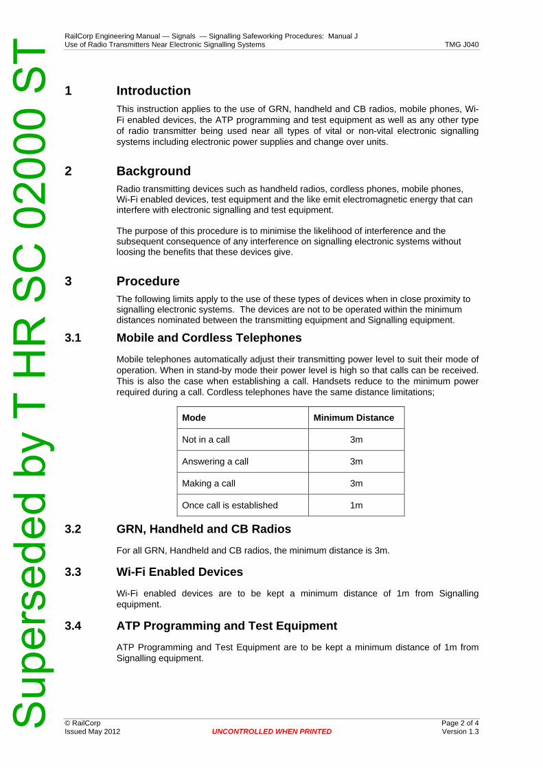
RailCorp Engineering Manual — Signals — Signalling Safeworking Procedures: Manual J Use of Radio Transmitters Near Electronic Signalling Systems TMG J040
© RailCorp Page 2 of 4 Issued May 2012 UNCONTROLLED WHEN PRINTED Version 1.3
1 Introduction This instruction applies to the use of GRN, handheld and CB radios, mobile phones, Wi-Fi enabled devices, the ATP programming and test equipment as well as any other type of radio transmitter being used near all types of vital or non-vital electronic signalling systems including electronic power supplies and change over units.
2 Background Radio transmitting devices such as handheld radios, cordless phones, mobile phones, Wi-Fi enabled devices, test equipment and the like emit electromagnetic energy that can interfere with electronic signalling and test equipment. The purpose of this procedure is to minimise the likelihood of interference and the subsequent consequence of any interference on signalling electronic systems without loosing the benefits that these devices give.
3 Procedure The following limits apply to the use of these types of devices when in close proximity to signalling electronic systems. The devices are not to be operated within the minimum distances nominated between the transmitting equipment and Signalling equipment.
3.1 Mobile and Cordless Telephones
Mobile telephones automatically adjust their transmitting power level to suit their mode of operation. When in stand-by mode their power level is high so that calls can be received. This is also the case when establishing a call. Handsets reduce to the minimum power required during a call. Cordless telephones have the same distance limitations;
Mode Minimum Distance
Not in a call 3m
Answering a call 3m
Making a call 3m
Once call is established 1m
3.2 GRN, Handheld and CB Radios
For all GRN, Handheld and CB radios, the minimum distance is 3m.
3.3 Wi-Fi Enabled Devices
Wi-Fi enabled devices are to be kept a minimum distance of 1m from Signalling equipment.
3.4 ATP Programming and Test Equipment
ATP Programming and Test Equipment are to be kept a minimum distance of 1m from Signalling equipment.
Sup
erse
ded
by T
HR
SC
020
00 S
T

RailCorp Engineering Manual — Signals — Signalling Safeworking Procedures: Manual J Use of Radio Transmitters Near Electronic Signalling Systems TMG J040
© RailCorp Page 3 of 4 Issued May 2012 UNCONTROLLED WHEN PRINTED Version 1.3
3.5 Other Transmitting Devices not listed
Where other known transmitting devices are being used, the minimum distance is 3m.
3.6 Test Equipment
The readings displayed on test equipment can be affected (and in error) when used in close proximity to a radio transmitting device. Tong or clamp meter current measurements are made by detecting electromagnetic fields and will be more significantly affected.
Measurements for certification of signalling equipment are not to be made within the minimum distances nominated in this procedure.
Sup
erse
ded
by T
HR
SC
020
00 S
T
RailCorp Engineering Manual — Signals — Signalling Safeworking Procedures: Manual J Use of Radio Transmitters Near Electronic Signalling Systems TMG J040
© RailCorp Page 4 of 4 Issued May 2012 UNCONTROLLED WHEN PRINTED Version 1.3
This page has been intentionally left blank
Sup
erse
ded
by T
HR
SC
020
00 S
T

RailCorp Engineering Manual — Signals — Signalling Safeworking Procedures: Manual J Pole Route TMG J041
© RailCorp Page 1 of 6 Issued May 2010 UNCONTROLLED WHEN PRINTED Version 1.1
TMG J041
POLE ROUTE
Version 1.1
Issued May 2010
Document control
Version Date Summary of change 1.0 September 2005 Replaced SC 00 52 00 41 SI Pole Route. 1.1 May 2010 Application of TMA 400 format
Contents 1 Introduction .............................................................................................................................2 2 Prevention of Accidents.........................................................................................................2
2.1 Responsibility of Linesmen in Charge .......................................................................2 2.2 Testing Poles before Climbing...................................................................................2 2.3 Ladders used in Climbing Poles ................................................................................3 2.4 Body Belts..................................................................................................................3 2.5 Linewires....................................................................................................................3 2.6 Line Poles, Erection, Alteration, Removal .................................................................3 2.7 Temporary Poles to be Stayed ..................................................................................4 2.8 Dangerous Poles .......................................................................................................4 2.9 Linesmen not to Climb Poles with Condemned Mark (X)..........................................4 2.10 Erection of Poles or Wires in vicinity of Transmission Lines .....................................4
3 Safe Working Instrument Line Wires ....................................................................................4 3.1 Precautions to be observed when handling...............................................................4 3.2 Transpositions ...........................................................................................................5
4 Signalling Power Mains Erected on RailCorp Poles ...........................................................5 5 Stay Wires................................................................................................................................5 6 Clearing Growth from Line Routes .......................................................................................5
Sup
erse
ded
by T
HR
SC
020
00 S
T
RailCorp Engineering Manual — Signals — Signalling Safeworking Procedures: Manual J Pole Route TMG J041
© RailCorp Page 2 of 6 Issued May 2010 UNCONTROLLED WHEN PRINTED Version 1.1
1 Introduction Suitably accredited linesmen are responsible for the maintenance of the signalling and communications line pole routes on their respective areas, but the Signalling Maintainer is responsible for the efficiency of the circuits operating over the linewires, and shall become conversant with the methods of installation and maintenance. Linesmen and Signalling Maintainers shall co-operate fully during testing and fault finding.
Linesmen are to make regular maintenance inspections as programmed by the Maintenance Signal Engineer and TMP of all pole routes on their sections. In addition to the checking of line wire tension, line wire insulation, stay wires, other fittings, clearance over roadways, growth of trees, etc., each pole should be tested and if considered dangerous must be adequately strengthened until renewal is possible.
Linewires used for signalling, safeworking and communications circuits shall be maintained as free as possible from any type of fault. It is the duty of linesmen and Signalling Maintainers to observe the linewires whilst travelling their areas and take immediate action to rectify any fault or have potential faults attended to promptly.
All line pole route maintenance, testing and faulting shall also be carried out in accordance with:
Booklet S.R.A. 81-12 Line Route Maintenance and Construction. Question and Answers.
2 Prevention of Accidents NOTICE
Linesmen are not to ascend any pole in course of erection until it has been properly set in the ground and the whole of the earth filled in and rammed.
2.1 Responsibility of Linesmen in Charge
Linesmen in charge of work are to clearly understand that they will be held responsible for seeing that every possible care is exercised to prevent accidents, that all gear is in good order, that any pole used as a derrick is sound, that the hooks of all pulley blocks are moused and that they alone issues orders during the lifting of the pole.
2.2 Testing Poles before Climbing
Before any linesman climbs a pole it is to be tested. When working in parties the responsibility for this test rests with the leading or senior linesman in charge of the gang. An effort should be made to force the pole over by pushing against it across the line of the wires. Though this test is not conclusive in the majority of cases, it will be sufficient to disclose any serious weakness in the pole. If there is still any doubt as to the condition of a pole, additional tests should be made:-
a) by opening up the ground for a depth of about 300 to 400 mm, and then hitting the edges at the foot of the pole by means of a bar or with a tomahawk to determine its soundness.
b) by applying a force as near the top of the pole as possible. It could be applied by two linesmen using a long pike giving the pole a swing, or by placing a ladder against the pole and applying a push-over as near the top of the pole as possible.
Sup
erse
ded
by T
HR
SC
020
00 S
T

RailCorp Engineering Manual — Signals — Signalling Safeworking Procedures: Manual J Pole Route TMG J041
© RailCorp Page 3 of 6 Issued May 2010 UNCONTROLLED WHEN PRINTED Version 1.1
c) by boring wooden poles with an auger bit to ascertain the amount of sound timber.
2.3 Ladders used in Climbing Poles
Before using a ladder it must carefully be examined with a view to ensuring that is in sound condition appropriate to the task, and placed in a safe working position. All ladders used should be non metallic and properly fitted with tie-bolts.
Where ladders are used in climbing poles, care must be taken that the bottom of the ladder is secured from slipping. The distance from the base of the pole to the foot of the ladder should be approximately one quarter of the length of the ladder. The ladder should always be tied to the pole at the top, and in any case where there is a liability of the ladder slipping, owing to the unevenness of the ground or unusual spread, the ladder should be also secured by tying to the pole at or near the foot. Linesmen must not stand on the top of the stiles.
On no account must one ladder be placed against a pole and another then rested on its top, nor should ladders be joined together.
Unless under very exceptional circumstances, more than one linesman shall not stand upon a ladder at one time, and where it is necessary to send up additional tools, etc., this should be done by passing down a rope.
Ladders shall not be placed against crossarms as these may break or shift under weight.
2.4 Body Belts A safety belt or body line must always be used when climbing poles.
2.5 Linewires
a) When handling a line wire it shall be held near to the end to avoid injury due to the line wire flicking.
b) When line wires are being removed from a line pole which is stayed (as at angle or termination) the strain of the stay-wire shall be counteracted by a temporary strut or stay before the lines are cut.
2.6 Line Poles, Erection, Alteration, Removal
The erection, alteration, and removal of poles must only be undertaken with an adequate number of linesmen and, should any difficulty arise, the linesman in charge of the work should at once communicate (by telephone if possible) with the Maintenance Signal Engineer
When erecting a new pole in place of another, upon the erection of the new pole the old one is to be, if possible, be securely lashed to it within a few feet of the top, so that is will not be possible for the old pole to fall when linesman are working on it. If this cannot be done, the old pole is to be temporarily stayed fore and aft and also side-stayed, so that it will be perfectly safe for linesmen to work on it.
The digging out of an existing pole must not be commenced until the linesmen have completed the removal of the wires and descended to the ground. Under no conditions shall a pole be even partially dug out before or during the time that the linesmen are dismantling the wires from it. Where the poles are set in concrete they should be cut off at ground level.
Sup
erse
ded
by T
HR
SC
020
00 S
T

RailCorp Engineering Manual — Signals — Signalling Safeworking Procedures: Manual J Pole Route TMG J041
© RailCorp Page 4 of 6 Issued May 2010 UNCONTROLLED WHEN PRINTED Version 1.1
2.7 Temporary Poles to be Stayed
When temporary poles are erected in connection with any work, they shall be adequately stayed before linesmen are permitted to work upon them.
2.8 Dangerous Poles
Nothing is to stand in the way of renewing or adequately strengthening any dangerous poles, and such work shall always be considered as of primary urgency. Records shall be kept showing the date on which poles were condemned and the dates they are renewed.
2.9 Linesmen not to Climb Poles with Condemned Mark (X)
Where wood poles have been condemned as dangerous and unfit to climb, they shall be marked with one cross (X), and all linesmen are forbidden to climb any pole bearing such a mark.
If it is necessary to access hardware or linewires attached to the pole then an Elevated Platform vehicle (EPV) is to be used. Refer to Safety Standard A10-02-N111 for elevated work platforms.
2.10 Erection of Poles or Wires in vicinity of Transmission Lines
Where poles or wires are to be erected in the vicinity of transmission lines approval is required from the Principal Engineer Electrical Design.
The minimum clearance between transmission lines and signalling and communication linewires and poles shall be in accordance with the following table:
VOLTAGE NOT EXCEEDING A SPAN LENGTH OF
60.0m 100m 120m Up to 650 Volts 1.20m 1.40m 1.50 Above 650 but not exceeding 22,000 volt 1.80m 2.00m 2.10m
Above 22,000 but not exceeding 33,000 volts 2.00m 2.10m 2.30m
Above 33,000 but not exceeding 66,000 volts 2.10m 2.30m 2.60m
Above 66 000 but not exceeding 132,000 volts 3.80m 4.20m 4.70m
Above 132 000 volts BY APPROVAL
3 Safe Working Instrument Line Wires 3.1 Precautions to be observed when handling
Where line wire returns are in use for safe working instruments, under no circumstances must the leading-in wires or jumper wires used at intermediate points be disconnected and re-connected by the linesman without the Signalling Maintainer being present. When work involving the disconnection of these wires is necessary, the Signalling Maintainer and linesman must work in conjunction, and the former will be responsible for seeing that the wires are re-connected correctly and the instruments subsequently tested and certified correct.
Sup
erse
ded
by T
HR
SC
020
00 S
T

RailCorp Engineering Manual — Signals — Signalling Safeworking Procedures: Manual J Pole Route TMG J041
© RailCorp Page 5 of 6 Issued May 2010 UNCONTROLLED WHEN PRINTED Version 1.1
3.2 Transpositions
Safeworking instrument line wires must not be transposed. Any transpositions found in safeworking instrument line wires must be brought to the attention of the Maintenance Signal Engineer.
4 Signalling Power Mains Erected on RailCorp Poles Before carrying out any repairs on aerial conductors, and where those conductors carry 120v circuits, or where there is a risk of coming into contact with circuits that carry 120v, the linesman should arrange with the Signalling Maintainer for the power supply to be cut off during the time the work is in hand.
Where possible, the work should be carried out during the time the section is unoccupied. Insulating rubber gloves must be used by the linesman.
Attention is drawn to the serious risks involved when staff are working on line wires or poles adjacent to power substations, electric power supply lines or other conductors carrying high voltages and, before any work is undertaken at locations where their is any possibility of contact with 'live' conductors, it will be the personal responsibility of the employee in charge of the work to see that the supply is disconnected.
It should be borne in mind at all times that any power conductor must be regarded as 'alive'. Should any doubt exist in this regard, work must not be allowed to proceed until investigations have been made and action taken accordingly. This would include testing for voltage on the wires to confirm disconnection by use of a meter, testing that equipment is no longer functioning.
5 Stay Wires A clearance of not less than 50mm must be maintained between stay wires and line wires.
Stay wires to be renewed shall not be removed before the new wires have been fixed unless temporary stay wires are used.
6 Clearing Growth from Line Routes It is the responsibility of all Maintenance Linesmen to ensure that the line route is free from tree and scrub growth.
During patrols of the line route notes should be taken of areas needing attention, and work programs generated to remove excessive tree and scrub growth.
Overhanging branches should also be removed from above the route. If trees growing outside the RailCorp boundary are noted as a concern then every effort must be made to contact the property owner prior to any lopping taking place.
Sup
erse
ded
by T
HR
SC
020
00 S
T
RailCorp Engineering Manual — Signals — Signalling Safeworking Procedures: Manual J Pole Route TMG J041
© RailCorp Page 6 of 6 Issued May 2010 UNCONTROLLED WHEN PRINTED Version 1.1
This page has been intentionally left blank
Sup
erse
ded
by T
HR
SC
020
00 S
T

RailCorp Engineering Manual — Signals — Signalling Safeworking Procedures: Manual J Safety Issues for Signalling Personnel TMG J042
© RailCorp Page 1 of 26 June 2011 UNCONTROLLED WHEN PRINTED Version 2.2
TMG J042
SAFETY ISSUES FOR SIGNALLING PERSONNEL
Version 2.2
June 2011
Document control
Version Date Summary of change Replaced Work on Signalling Power Mains TMG J042 v1.0 of
September 2005 1.0 September 2005 Reformat from SC 00 52 00 42 SI 2.0 June 2006 Fundamental change with new title and name change. 2.1 May 2010 Update 8.2 - SMS reference. Application of TMA 400 format 2.2 June 2011 Review, Update and reformatting where appropriate
Contents 1 Introduction .............................................................................................................................3 2 Basic Safe Work Principles....................................................................................................3 3 Electrical Work ........................................................................................................................4 4 Signalling Electrical System - AC Power..............................................................................5
4.1 Earth Leakage Faults.................................................................................................5 4.1.1 Assessment................................................................................................6 4.1.2 Actions........................................................................................................6
4.2 Power Supplies without ELDs ...................................................................................6 4.3 Independent Power Supplies.....................................................................................7 4.4 Emergency Change-Over Contactors .......................................................................7 4.5 Testing, Adjustment or Fault Finding – AC Circuits...................................................8 4.6 SSI Points Modules ...................................................................................................8 4.7 Work on Electrical Supply Transformers ...................................................................8 4.8 Isolation of Power Mains............................................................................................8
4.8.1 Test for De-energisation.............................................................................9 4.8.2 Work Carried out by the person doing the isolation ...................................9 4.8.3 Work Carried out by persons other than the person doing the
isolation ......................................................................................................9 4.8.4 Lost Permits .............................................................................................10 4.8.5 Unknown Danger Tags............................................................................10
4.9 AC Power Maintenance Activities............................................................................11 4.9.1 Testing of Earth Leakage Detectors.........................................................11 4.9.2 Enclosure of Equipment ...........................................................................11 4.9.3 Testing of Protective Enclosure Earthing.................................................11
Sup
erse
ded
by T
HR
SC
020
00 S
T
RailCorp Engineering Manual — Signals — Signalling Safeworking Procedures: Manual J Safety Issues for Signalling Personnel TMG J042
© RailCorp Page 2 of 26 June 2011 UNCONTROLLED WHEN PRINTED Version 2.2
5 Signalling DC Circuits ..........................................................................................................11 5.1 Earth Leakage Faults...............................................................................................11
5.1.1 Assessment..............................................................................................11 5.1.2 Actions......................................................................................................12
5.2 Secondary Batteries ................................................................................................12 5.2.1 Safety Precautions with Secondary Batteries ..........................................12 5.2.2 Vented Cell Batteries................................................................................13 5.2.3 Sealed Cell Batteries................................................................................14
5.3 Capacitors................................................................................................................14 5.4 Electrical Work on DC Circuits ................................................................................14 5.5 Testing, Adjustment or Fault Finding – DC Circuits ................................................15 5.6 SSI Points Modules .................................................................................................15
6 Signalling Compressed Air System ....................................................................................16 7 Touch Potentials on Metalwork ...........................................................................................17 8 Traction Return .....................................................................................................................18
8.1 Spark Gap Connections...........................................................................................18 9 Test Equipment .....................................................................................................................19
9.1 Test Leads ...............................................................................................................19 9.2 Test Equipment Rating ............................................................................................19 9.3 Current Measurements ............................................................................................19 9.4 Megger and Bell Megger .........................................................................................20 9.5 Integrators for Jeumont Track Circuits ....................................................................20 9.6 Insulated Tools, Insulating Covers, Mats and Gloves .............................................20
10 Impulse Track Circuits - Precautions..................................................................................21 11 Resonated Impedance Bonds..............................................................................................21 12 Fibre Optics and Lasers .......................................................................................................21 13 Equipment Hazards...............................................................................................................22 14 Hazardous Materials .............................................................................................................22 15 Rail Drilling ............................................................................................................................23 16 Cadwelding ............................................................................................................................23 17 Working at Heights ...............................................................................................................24 18 Confined or Restricted Spaces............................................................................................24 19 Excavations ...........................................................................................................................24 20 Manual Handling ...................................................................................................................24 21 Work in Old Signalling Locations........................................................................................25 22 Mechanical Lever Frames ....................................................................................................25 23 Superseded Instructions......................................................................................................25
Sup
erse
ded
by T
HR
SC
020
00 S
T
RailCorp Engineering Manual — Signals — Signalling Safeworking Procedures: Manual J Safety Issues for Signalling Personnel TMG J042
© RailCorp Page 3 of 26 June 2011 UNCONTROLLED WHEN PRINTED Version 2.2
1 Introduction RailCorp has a Safety Management System (SMS), which details RailCorp’s policy, processes and procedures for a safe work environment. The documents are held in the SMS area of the RailCorp intranet.
General electrical installations are covered by SMS Element 06 Risk Management, OHS Risk Management: Electrical Safety guides and instructions.
This procedure highlights safety issues that are specific to the Signalling System.
The “Occupational Health and Safety Regulation 2001” covers a broad range of matters affecting the health of persons in a workplace, including referring to ‘work’ on ‘electrical installations’. Australian Standard AS 4836 Safe Working on low-voltage Electrical installations outlines principles and procedures of safe work, organisation and performance on or near low-voltage electrical equipment.
WorkCover NSW has issued a Code of Practice for Low Voltage Electrical Work. This Code of Practice is focused on standard AS 3000 compliant installations, but provides useful information on safe work methods and risk management for electrical work.
Both the Australian Standard AS 4836 and the WorkCover NSW Code of Practice for Low Voltage Electrical Work have been used as significant sources for the development of this procedure.
This procedure:
• Alerts personnel to the typical issues and hazards that are particular to the signalling system.
• Identifies issues that personnel working on the signalling system need to consider for their own safety and the safety of others.
• Details actions signalling personnel must take to protect themselves.
A number of issues maybe common sense, however they need to be considered when performing work on the signalling system.
2 Basic Safe Work Principles The basic principles for working safely are to assess hazards and then remove them, or implement mitigation measures to reduce the risk of those hazards by:
a) Setting up a safe work area.
b) Preventing the work from causing a hazard for others. e.g. signalling safety hazards due to the work, or other people nearby.
c) Managing the electrical hazards by:
i) Isolation and proven de-energised as applicable and/or
ii) Temporary use of insulation or covers to prevent the hazards of electric shock and flash burns due to accidental short circuits and/or
iii) Use of a safety observer.
d) Managing the physical hazards due to operation of equipment by disconnection, isolation, or physical disabling of equipment.
e) Training staff in First Aid to render assistance.
Sup
erse
ded
by T
HR
SC
020
00 S
T

RailCorp Engineering Manual — Signals — Signalling Safeworking Procedures: Manual J Safety Issues for Signalling Personnel TMG J042
© RailCorp Page 4 of 26 June 2011 UNCONTROLLED WHEN PRINTED Version 2.2
3 Electrical Work All work on Signalling electrical systems is to be carried out by, or under the direct supervision of, persons trained and accredited to do so.
TMG J001 – Introduction to Signalling Maintenance Procedures details the accreditation and authorization of personnel.
The term electrical work in the context of the signalling systems refers to any changes to wiring, including connection or disconnection of fuses or links on open terminal blocks, or the removal or installation of un-insulated wires and lugs on terminations, or jointing and termination of cables irrespective of working voltage.
The term electrical work does not include: the closing or opening of switches, or the removal or replacement of fuses or link pins in fully enclosed (SAK type) terminal blocks, or use of a meter to measure voltage, or the use of a current tong or current clamp.
A test to prove that the circuit is de-energised is required before work commences. Any wiring changes or re-termination of signalling AC circuits at any voltage shall be carried out with the circuit isolated and proven de-energised by use of a meter. Section 4.8.1 details the test method.
The methods of isolation are detailed in TMG J008 – Booking Equipment Out of Use and TMG J009 – Disconnection of Signalling Apparatus.
Work that requires touching of wires or wiring but is unlikely to risk contact with potentials above the limits of 25VAC or 60VDC is not considered electrical work. If it is likely that contact with potentials above the limits of 25VAC or 60VDC can occur then it is considered to be electrical work. Exposed terminals, or exposed conductors, with potentials above the limits of 25VAC or 60VDC are considered to represent a likely risk of contact.
The voltage limits have been set based on PELV values that do not require protection against direct contact as per Section 1.5.7 of AS 3000:2007 Wiring Rules.
Some examples for hand tracing of wires in a relay room are:
a) Hand tracing of wires near exposed stud terminals for 120VAC circuits requires protection by an insulating cover against direct contact with the terminals or is considered to be electrical work and requires isolation.
b) Hand tracing of wires near SAK fuses and terminals for 120VAC circuits is not considered to be electrical work but should include in the pre-work brief that the test points on the SAKC10 terminals and the front bussing on SAK4 terminals do not comply with touch proof requirements and a possible risk of direct contact with potentials above 25VAC or 60VDC exists.
Adjacent circuits (particularly those below the work area) that have exposed terminals must be insulated or isolated prior to work.
Sup
erse
ded
by T
HR
SC
020
00 S
T

RailCorp Engineering Manual — Signals — Signalling Safeworking Procedures: Manual J Safety Issues for Signalling Personnel TMG J042
© RailCorp Page 5 of 26 June 2011 UNCONTROLLED WHEN PRINTED Version 2.2
A number of hazards exist within the signalling electrical system. These hazards and associated controls are:
Hazard Control Measure
Electric shock due to contact with live terminals
Work in accordance with the SMS and guidance provided by Sections 3, 4, 5, 7, 8, 9, 10, 11 and 21 of this procedure.
Electric shock due to stored electrical charge
Work in accordance with the SMS and guidance provided by Sections 5.3, 9.4 and 9.5 of this procedure.
Arc, blast and flash injuries Work in accordance with the SMS and guidance provided by Sections 3, 4, 5, 8 and 9 of this procedure.
Physical injury from equipment operation
Work in accordance with the SMS and guidance provided by Sections 4.4 and 13 of this procedure.
Toxic substances and gases from secondary batteries
Work in accordance with the SMS and guidance provided by Section 5.2 of this procedure.
4 Signalling Electrical System - AC Power Signalling electrical system power distribution generally conforms to the Isolation Transformers (IT) system of earthing (unearthed) as detailed in IEC 60364 Electrical Installations in Buildings. This system uses isolation transformers to provide an AC power supply system that does not rely on earth connections for safety of people or property.
The basis for the alignment of the signalling power supply to the IT system of earthing is:
a) By maintaining high impedance to earth, any fault currents to earth are limited. This in turn prevents false operation of signalling safety equipment, and allows power to be maintained whilst faults are found and corrected.
b) By maintaining a high impedance to earth, body shock currents due to contact with live conductors are limited.
c) The use of an earth leakage detector (known as a permanent insulation monitor in the standard) with the IT system allows detection and subsequent correction of any compromised insulation prior to a hazardous situation occurring.
At supply points to the signalling electrical system, equipment on the supply side of the signalling supply step-down or isolating transformers is excluded from these instructions. These transformers are subject to SMS Element 06 Risk Management, OHS Risk Management: Electrical Safety guides and instructions..
4.1 Earth Leakage Faults
The use of Earth Leakage Detectors (ELDs) allows detection of any compromised insulation prior to or when a potentially hazardous situation occurs.
If a short circuit earth fault occurs on one leg of the 120VAC signalling power supply then contact with the other leg can result in an electric shock that could harm a person.
If two faults occur on one signalling AC power supply then it is possible for a “touch potential” to exist between the case of one faulty item of equipment and earth that exceeds the internationally accepted limit of 50VAC.
Sup
erse
ded
by T
HR
SC
020
00 S
T

RailCorp Engineering Manual — Signals — Signalling Safeworking Procedures: Manual J Safety Issues for Signalling Personnel TMG J042
© RailCorp Page 6 of 26 June 2011 UNCONTROLLED WHEN PRINTED Version 2.2
For example, if a fault occurs where Nx120 is short circuit to earth at a location, and then a second fault occurs in a train stop with Bx120 short circuit to the train stop case, the fuse may not “blow”, and a person touching the particular train stop case may receive an electric shock.
As a result of the potential signalling safety hazard and the electrical safety hazard for personal that work on the signalling equipment it is necessary to rectify the causes of ELD alarms as a high priority.
4.1.1 Assessment
The maintainer must assess each AC ELD fault to determine if an immediate Signalling safety hazard or electrical safety hazard exists. If the fault causes a measured voltage of more than:
• 75 volts from either leg of the supply to earth for a 120V supply; or • 80% of the nominal voltage for extended voltage supplies
e.g. 332 volts on a 415 volt supply,
then the AC power supply shall be considered as hazardous. Voltages are measured using a 100KΩ shunt across the multimeter.
Higher voltages to earth may be acceptable in some cases. Such cases should be submitted to the Chief Engineer Signals and Control Systems for consideration.
4.1.2 Actions
If the signalling AC power supply is considered hazardous based on the assessment then treat all exposed terminals and field equipment as potentially the source of a serious electric shock and the fault must be found and isolated or corrected. If the fault is unable to be found or isolated then advise the Maintenance Signal Engineer. Action must then be taken to manage the hazard until it can be rectified.
If the earth fault results in an assessment that it is not hazardous then the earth fault is to be addressed as part of routine maintenance, with a priority equal to other routine safety critical maintenance tasks. The earth fault must be monitored at least weekly until corrected. Regular monitoring is required to confirm that a second fault has not occurred.
Report any items of external equipment (not equipment installed within locations as it is inherently connected to the location earth) that have had faults to exposed metalwork to the Chief Engineer Signals and Control Systems to determine appropriate equipment design changes to prevent re-occurrence.
4.2 Power Supplies without ELDs A number of older locations do not have ELDs fitted to the 120VAC supply.
Some power supplies like the secondary of SSI isolation transformers do not have ELDs fitted.
Prior to working in locations that do not have ELDs fitted, where it is possible to come in contact with exposed terminals, a check of the voltage between both Bx and Nx to earth of the supply is required using a 100KΩ shunt across the multimeter.
If the measured voltage is more than:
• 75 volts from either leg of the supply to earth for a 120 volt supply
then the AC power supply shall be considered as hazardous.
Sup
erse
ded
by T
HR
SC
020
00 S
T

RailCorp Engineering Manual — Signals — Signalling Safeworking Procedures: Manual J Safety Issues for Signalling Personnel TMG J042
© RailCorp Page 7 of 26 June 2011 UNCONTROLLED WHEN PRINTED Version 2.2
Higher voltages to earth may be acceptable in some cases:
• The 110 volt supply for SSI TFMs may have up to 100 volts from either leg of the supply to earth before being considered hazardous due to inherent imbalances.
• Other cases should be submitted to the Chief Engineer Signals and Control Systems for consideration.
If the signalling AC power supply is considered hazardous based on the assessment then treat all exposed terminals and field equipment as potentially the source of a serious electric shock. Find and isolate or correct the fault. If the fault is unable to be found or isolated then advise the Maintenance Signal Engineer. Action must then be taken to manage the hazard until it can be rectified.
If the earth fault results in an assessment that it is not hazardous then the earth fault is to be addressed as part of routine maintenance, with a priority equal to other routine safety critical maintenance tasks. The earth fault must be monitored at least weekly until corrected. Regular monitoring confirms that a second fault has not occurred.
Report any items of external equipment (not equipment installed within locations as it is inherently connected to the location earth) that have had faults to exposed metalwork to the Chief Engineer Signals and Control Systems to determine appropriate equipment design changes to prevent re-occurrence.
4.3 Independent Power Supplies
The two independent power supplies provided at power locations may have the same or different phasing, meaning that if the two independent supplies were connected together, then voltages of up to twice the supply voltage could occur between different parts of the circuit.
If testing requires the commons / Nxs to be temporarily connected to test phasing then:
a) Ensure no other work is being done on either power supply.
b) Apply a temporary connection between Nxs by approved controlled bridge/s.
c) Use test equipment rated for the maximum potential voltages. This is not normally a problem with standard test equipment for 120V, but may not be rated for voltages that could occur at higher supply voltages.
d) Remove the temporary connection between Nxs.
e) Test independence of supplies (if appropriate) after the removal of the bridge/s, by measuring voltage between the Bx of one supply and the Nx of the other supply and then Nx to Nx to confirm the voltages are below 30V. A 100KΩ shunt is not required across the multimeter for this measurement.
4.4 Emergency Change-Over Contactors
Emergency Change Over contactors (ECO) as well as operating with high force and speed have two independent sources of power supply. Isolation of both supplies to the ECO requires the booking out of use of a large quantity of signalling equipment, and this is to be avoided if possible.
Work within an ECO cabinet using block contactors may only be carried out when:
a) one incoming supply is isolated and proven de-energised by use of a meter, and
b) the remaining supply terminals are insulated by insulating barriers or covers to control the risk of flash burns due to accidental short circuits.
Sup
erse
ded
by T
HR
SC
020
00 S
T

RailCorp Engineering Manual — Signals — Signalling Safeworking Procedures: Manual J Safety Issues for Signalling Personnel TMG J042
© RailCorp Page 8 of 26 June 2011 UNCONTROLLED WHEN PRINTED Version 2.2
or
c) both supplies are isolated and proven de-energised by use of a meter.
Work within an ECO cabinet using bar contactors may only be carried out when:
a) one incoming supply is isolated and proven de-energised by use of a meter, and,
b) the remaining supply terminals are insulated by insulating barriers or covers to control the risk of flash burns due to accidental short circuits, and
c) a barrier or physical separation is fitted to protect against harm due to operation of the contactor.
or
d) both supplies are isolated and proven de-energised by use of a meter.
4.5 Testing, Adjustment or Fault Finding – AC Circuits
Signalling testing, adjustment and fault finding on circuits or mains at a nominal 120V that are protected by fuse or circuit breaker rated at;
• more than 25 amps require control measures to be in place to prevent short circuit faults whilst testing without isolation. Safety glasses and long sleeves are to be worn to protect against the risk of flash burns.
• up to 25 amps is permitted without isolation.
Adjustment and fault finding on AC circuits at voltages more than the nominal 120V is not permitted without isolation. However, voltage measurement with a meter and current measurement with a current clamp or tong meter is permitted without isolation.
Current clamps or tong meters are to be used for current measurements in circuits that are protected by a fuse or circuit breaker rated at more than 10A.
4.6 SSI Points Modules
SSI points modules use 140VAC for the motor outputs. The 140VAC is fed from an isolation transformer via the ESML contacts to the points module.
The 140VAC circuits for SSI points modules are limited and do not represent a significantly different hazard to the normal 120VAC installation.
The 140VAC circuits for the SSI points modules should be treated as per the normal 120VAC circuits.
4.7 Work on Electrical Supply Transformers
Power isolating transformers provide power to the signalling system and form one of the interfaces to the electrical discipline.
Electrical work on and adjustment of electrical supply power isolating transformers must be in accordance with SMS Element 06 Risk Management, OHS Risk Management: Electrical Safety guides and instructions. This will require a “Low Voltage Access Permit” to be issued by the electrical discipline.
4.8 Isolation of Power Mains Isolation of the signalling power mains is by:
Sup
erse
ded
by T
HR
SC
020
00 S
T
RailCorp Engineering Manual — Signals — Signalling Safeworking Procedures: Manual J Safety Issues for Signalling Personnel TMG J042
© RailCorp Page 9 of 26 June 2011 UNCONTROLLED WHEN PRINTED Version 2.2
a) Opening the supply-side circuit breaker or isolator (which isolates both legs of the circuit).
b) Securing the operating lever in the open position by affixing a tie through the holes provided for this purpose. The tie may be the same used to affix the label (see following).
c) Identifying the circuit breaker or isolator as having been deliberately isolated by attaching a label or danger tag showing the name of the person who affixed the tag, the date and the reason for the isolation.
d) Testing that the power mains are “dead” as close as practical to the actual work location to confirm that the power is off.
4.8.1 Test for De-energisation
A test for de-energisation consists of using a multimeter on AC voltage (with a 100KΩ shunt across the multimeter) to check:
• A live circuit has voltage to prove that the meter works.
Then:
a) Bx to Nx has no voltage (<1VAC on meter).
b) Bx to Earth has no voltage (<1VAC on meter).
c) Nx to Earth has no voltage (<1VAC on meter).
The earth for the test is the nearest metalwork bonded to earth. If no metalwork is nearby then one probe is pushed into the ground (dirt, not concrete or floor covering).
4.8.2 Work Carried out by the person doing the isolation
If the work to be carried out is being done by the person who does the isolation, then no further action is required.
4.8.3 Work Carried out by persons other than the person doing the isolation
If the work is to be carried out by persons other than the person who will be isolating and restoring the circuit, then before commencement of any work the Signal electrician or engineer in charge shall:
• Isolate, identify and test de-energisation of the circuit as per 4.8 and 4.8.1 above.
• Complete a “LOW VOLTAGE ACCESS PERMIT” which is available as Stock code 1886910.
• The permit number shall be of the form “SIGNALS/ggggg/xx/yymmdd/n” where “ggggg” identifies the work area issuing the permit, “xx” is the initials of the person issuing the permit, “yymmdd” is the date the permit is issued in year, month, day, and “n” is a sequence number for the day (1 to 9). For example SIGNALS/strath/pz/060116/1.
• A separate danger tag is applied to the circuit breaker or isolator and a separate permit issued for each work group.
• If multiple isolations are required and work could be done so that the permits can be progressively handed back then the issue of multiple danger tags and permits is preferred. The additional danger tags can be tied to the first tag.
Sup
erse
ded
by T
HR
SC
020
00 S
T

RailCorp Engineering Manual — Signals — Signalling Safeworking Procedures: Manual J Safety Issues for Signalling Personnel TMG J042
© RailCorp Page 10 of 26 June 2011 UNCONTROLLED WHEN PRINTED Version 2.2
While the work is ongoing the permit holder shall comply with the instructions printed on the reverse of the permit. The key instructions include:
a) The work description on the permit. This fully describes the work to be carried out. No work may be carried out on or near the isolated equipment other than that specified on the permit.
b) The low voltage equipment that is covered by the permit. Persons carrying out the work must understand which low voltage equipment is covered by the permit and is safe to work on or near. All other exposed equipment must be treated as live.
c) Warnings for persons carrying out the work:
i) not to allow any part of their bodies, clothes, tools or materials they may be using or carrying, to come within the electrical safe working distances of any exposed equipment, other than the isolated equipment in the electrically safe work area, and
ii) not to pass over or under work area markers, safety fences or other barriers.
d) Adequate work process controls to ensure that persons do not work beyond the limits of the electrically safe work area.
e) Precautions required prior to the permit being returned. Before returning the permit all persons and material are to be clear of all low voltage equipment for which the permit was issued, and have been instructed to treat the equipment as live.
On completion of the work:
f) The permit holder and the work party sign off the work as being complete and return the “Low Voltage Access Permit” form to the signalling person in charge.
g) The signalling person in charge countersigns the form, removes the danger tag for that permit, and restores the power when all danger tags have been removed.
4.8.4 Lost Permits
If a permit has been lost while the work is still in progress then a duplicate permit is to be issued and all personnel must re-sign. The duplicate must be endorsed “Replacement for lost permit”.
If a permit has been lost after the work has been completed, but before returning it to the signalling person in charge, then written confirmation from each workgroup is required that they have completed their work to confirm that the permit is no longer required. This is to be done on the duplicate copy.
4.8.5 Unknown Danger Tags
If a danger tag is found and its reason for being in place is unclear or unknown then the danger tag may need to be overridden.
To override a danger tag, the Maintenance Engineer, Signals and Signal Planning Engineer must consult and confirm that the danger tag is not valid as:
• There is no work occurring where the isolation has taken place, and • The circuit is safe to be re-energised.
Sup
erse
ded
by T
HR
SC
020
00 S
T

RailCorp Engineering Manual — Signals — Signalling Safeworking Procedures: Manual J Safety Issues for Signalling Personnel TMG J042
© RailCorp Page 11 of 26 June 2011 UNCONTROLLED WHEN PRINTED Version 2.2
The Maintenance Engineer, Signals and Signal Planning Engineer can then jointly authorise the removal of an unknown danger tag.
4.9 AC Power Maintenance Activities
4.9.1 Testing of Earth Leakage Detectors
All ELDs must be tested by operation of the push button provided on the device to confirm that the device, alarms and indications function correctly. These intervals are specified in the Technical Maintenance Plan Service Schedules.
4.9.2 Enclosure of Equipment
All equipment operating at voltages above 120V nominal must have the protective enclosures in position and correctly secured at all times. Covers may be removed for testing purposes only, or when the equipment has been isolated to permit work to take place.
Where work is undertaken within an enclosure where only partial isolation has occurred, then all live parts are to be temporarily enclosed before work commences. These arrangements are to be approved by a responsible Engineer.
All covers are to be reinstated if the location is to be left unattended.
4.9.3 Testing of Protective Enclosure Earthing
All power supply equipment operating at voltages above 120V nominal are housed within a protective cover, where any metal components are earthed.
The Technical Maintenance Plan and/or Service Schedules must include two yearly tests to ensure that the resistance from these metal covers and enclosures to the main earth busbar does not exceed 2Ω. This test should be aligned with the power supply insulation test.
5 Signalling DC Circuits Signalling DC circuits are unearthed.
The reason for maintaining earth free circuits is to prevent false operation of signalling safety equipment due to a single earth fault. A secondary benefit is the reduced risk of electric shock by contact with one live conductor.
5.1 Earth Leakage Faults
The use of ELDs allows detection of any compromised insulation prior to or when a hazardous situation occurs.
As a result of the potential significant signalling safety hazard and the potentially minor electrical safety hazard for personnel that work on the signalling equipment it is necessary to rectify causes of ELD faults as a high priority.
5.1.1 Assessment
The maintainer must assess each DC ELD fault to determine if an immediate signalling safety hazard or electrical safety hazard exists. If the fault causes a measured voltage of more than:
• 40 volts from either leg of the supply to earth for a 50 volt supply; or • 80% of the nominal voltage for extended voltage supplies
Sup
erse
ded
by T
HR
SC
020
00 S
T

RailCorp Engineering Manual — Signals — Signalling Safeworking Procedures: Manual J Safety Issues for Signalling Personnel TMG J042
© RailCorp Page 12 of 26 June 2011 UNCONTROLLED WHEN PRINTED Version 2.2
e.g. 56 volts on a 70 volt supply
then the DC power supply shall be considered as hazardous.
Earth faults need to be responded to in accordance with the assessment to address the system safety hazard. 50VDC unfiltered supplies may just exceed the internationally accepted limits for touch potentials whereas 12VDC and 24VDC supplies do not.
5.1.2 Actions
If the signalling DC power supply is considered hazardous based on the assessment then treat all exposed terminals and field equipment as potentially the source of a minor electric shock. The fault must be found and isolated or corrected. If the fault is unable to be found or isolated then advise the Signal Maintenance Engineer. Action must then be taken to manage the hazard until it can be rectified.
If the earth fault results in an assessment that it is not hazardous then the earth fault is to be addressed as part of routine maintenance, with a priority equal to other routine safety critical maintenance tasks. The earth fault must be monitored at least weekly until corrected. Regular monitoring is required to confirm that a second fault has not occurred.
Report any items of external equipment (not equipment installed within locations as it has a connection to the location earth) that have faults to exposed metalwork to the Chief Engineer Signals and Control Systems to determine appropriate equipment design changes to prevent re-occurrence.
5.2 Secondary Batteries
DC battery installations are used at various locations at voltages up to 120 volts.
Always follow the manufacturer’s recommended procedures and safety instructions when handling or maintaining secondary batteries. Hazards include highly corrosive electrolytes, the capacity to generate very high currents through accidental short-circuits and the ability to generate highly explosive gases. Should a metal watchband or other jewellery accidentally short-circuit one or more cells, they can weld to the electrical terminals and quickly become hot enough to cause third degree burns or worse to the wearer.
Disposal of batteries must be in strict accordance with the Environmental guidelines or instructions.
Towards the end of a charge cycle or under overcharge conditions, electrolysis within a cell may cause amounts of hydrogen and oxygen to be generated.
The design of battery installations includes the provision of ventilation and the use of explosion-proof caps if vented cells are used.
Ventilation is important to prevent the build up of explosive gases around batteries. An explosion may occur if a spark is introduced to a combination of hydrogen and oxygen in a confined area. The explosion can have sufficient force to shatter the case of the cell and violently scatter electrolyte over the surroundings.
Vented batteries should not be used or if in use they should be identified and be planned for replacement in the medium term.
5.2.1 Safety Precautions with Secondary Batteries
The following precautions should be followed when installing, maintaining or recharging lead-acid or nickel-cadmium batteries;
Sup
erse
ded
by T
HR
SC
020
00 S
T
RailCorp Engineering Manual — Signals — Signalling Safeworking Procedures: Manual J Safety Issues for Signalling Personnel TMG J042
© RailCorp Page 13 of 26 June 2011 UNCONTROLLED WHEN PRINTED Version 2.2
a) use safety glasses and insulated tools.
b) do not wear metallic wristbands.
c) ensure there is adequate ventilation prior to starting work on or near batteries.
d) ensure that suitable fire fighting equipment is available. It may be in the vehicle.
e) ensure that non-sealed batteries have explosion-proof cell caps fitted to all cells, and kept closed on all except the one cell that is being maintained.
f) ensure ample clean water and an eyebath are available to treat a spill or splash to skin or especially eyes. Battery electrolytes are harmful – when handling wear protective clothing and eyewear. In the event of contact with skin or clothing wash immediately with running water and obtain immediate medical attention.
g) do not carry cigarettes, burning materials or sources of ignition such as mobile phones in the vicinity of open cells, or cells without explosion-proof caps.
h) when recharging batteries off-line ensure the area is well-ventilated and away from equipment or machines that produce sparks or flame.
i) use distilled water only for topping up of all cells.
j) battery terminals and wiring to the initial protection devices (e.g. fuse or circuit breaker) must not be left exposed or in a condition that allows accidental short circuiting of the battery output.
k) batteries and individual cells can exceed 20kg in mass. Manual handling precautions must be taken.
5.2.2 Vented Cell Batteries
Australian Standard AS2676.1:1990 Guide to installation, maintenance, testing and replacement of secondary batteries in buildings - Vented cells applies to battery installations of greater than 24V nominal and 10Ah capacity. The standard recommends:
a) Personal Protective Equipment – the minimum is face shield or goggles for water top up and acid resistant clothing and gloves.
b) Safety Signs: “Danger – Risk of Battery Explosion” on access doors and Electrolyte Burns emergency information in the room.
c) Water supply: Disposable sterile eye irrigators as minimum.
d) Precautions during installation and during maintenance that include PPE and general safety information.
e) Fire Fighting: Equipment for fighting electrical fires to be in the room.
Level crossing battery installations use vented cells and are below the 24V nominal and do not need to comply with the Australian Standard recommendations.
Telemetry 24V no break supply battery installations should comply with the Australian Standard recommendation.
50V no break supply battery installations must comply with the Australian Standard recommendation.
Eye wash facilities are to be provided for all installations of 100Ah or more. The presence and operation of the eyewash is to be checked prior to any work being done on or near the batteries.
Sup
erse
ded
by T
HR
SC
020
00 S
T
RailCorp Engineering Manual — Signals — Signalling Safeworking Procedures: Manual J Safety Issues for Signalling Personnel TMG J042
© RailCorp Page 14 of 26 June 2011 UNCONTROLLED WHEN PRINTED Version 2.2
5.2.3 Sealed Cell Batteries
Australian Standard AS2676.2:1992 Guide to installation, maintenance, testing and replacement of secondary batteries in buildings – Sealed cells applies to battery installations of greater than 24V nominal and 10Ah capacity. The standard recommends:
a) Personal Protective Equipment (PPE) – face shield or goggles and insulated tools.
b) Safety Signs: Restricted access and caution signs.
c) Precautions during installation and during maintenance that include PPE and general safety information.
d) Fire Fighting: Equipment for fighting electrical fires to be provided for installation.
Microlok II installation batteries are 12V and do not need to comply with the Australian Standard recommendations.
Telemetry 24V no break supply battery installations should comply with the Australian Standard recommendations.
50V no break supply battery installations must comply with the Australian Standard recommendations.
Battery installations for UPS or GGIs must comply with the Australian Standard recommendations.
5.3 Capacitors
A capacitor’s stored energy charge may remain for a long time after the power has been isolated or disconnected. The presence of capacitors must be considered before working on DC circuits or equipment. Circuits are to be proven de-energised before work is carried out.
The preferred method of disconnection in these cases is to disconnect the power to the supply first and then disconnect the load afterwards. This will normally discharge any capacitors.
5.4 Electrical Work on DC Circuits
Normally wiring changes on signalling DC circuits at any voltage shall be carried out with the circuit isolated and de-energised. The risks that these measures control are:
a) electric shock,
b) flash burn,
c) false energisation of an in-service circuit,
d) confusing signalling indications resulting from random energisation and de-energisation of circuits ‘downstream’ from the one being worked on.
e) accidental tripping of circuit protection upstream of the circuit being worked on, causing failures of multiple items of equipment.
f) damage to equipment due to intermittent or repeated disconnection and reconnection.
Re-termination of individual wires protected by a fuse of 4A or less, with a working voltage of 50VDC nominal or less using insulated tools without isolation should be
Sup
erse
ded
by T
HR
SC
020
00 S
T

RailCorp Engineering Manual — Signals — Signalling Safeworking Procedures: Manual J Safety Issues for Signalling Personnel TMG J042
© RailCorp Page 15 of 26 June 2011 UNCONTROLLED WHEN PRINTED Version 2.2
avoided. It is however permitted after a site specific risk assessment has been completed.
The methods of isolation are detailed in TMG J008 – Booking Equipment Out of Use and TMG J009 – Disconnection of Signalling Apparatus.
5.5 Testing, Adjustment or Fault Finding – DC Circuits
Signalling testing, adjustment and fault finding on circuits or mains that are protected by fuse or circuit breaker rated at:
• more than 25 amps requires control measures to prevent short circuit faults whilst testing without isolation. Safety glasses and long sleeves are to be worn to protect against the risk of flash burns.
• less than 25 amps is permitted without isolation.
Current Clamps or Tong meters are to be used for current measurements for circuits that are protected by a fuse or circuit breaker rated at more than 10A (or meter rating).
5.6 SSI Points Modules SSI Points modules use 120VDC for their valve outputs.
The 120VDC circuits from the SSI points modules must be de-energised before any electrical work.
The 120VDC circuits are normally limited to the NWRO, RWRO resistors, and NWR, RWR relays.
Sup
erse
ded
by T
HR
SC
020
00 S
T

RailCorp Engineering Manual — Signals — Signalling Safeworking Procedures: Manual J Safety Issues for Signalling Personnel TMG J042
© RailCorp Page 16 of 26 June 2011 UNCONTROLLED WHEN PRINTED Version 2.2
6 Signalling Compressed Air System Equipment operated by compressed air moves with both speed and force. A control measure must be put in place to prevent operation of equipment when work is being carried out on or near compressed air powered equipment. This may require isolation of the air supply to the particular item of equipment.
Australian Standard AS 4343:2005 Pressure equipment – Hazard levels is used to determine the hazard levels of the compressed air system. The calculated hazard level for the signalling compressed air system general pipe work is hazard level E (negligible hazard). The calculated hazard level for the air receivers depends on their size. The hazard level is typically hazard level C (low hazard) for receivers less than 3,000 litres capacity. Hazard level B (medium hazard) applies for receivers of more than 3,000 litres capacity.
Australian Standard AS 3788:2001 Pressure equipment – In-service inspection requires inspections for compressed air containing vessels based on the working pressure and volume.
Compressed air containing vessels used in the signalling compressed air system like:
• Air receivers of 150 litres or more in regulated air system • Air receivers or siphons of 300 litres or more used in the air line or unregulated air
systems.
must be registered with WorkCover as pressure vessels and are subject to regular inspections.
Any maintenance or alterations to air receivers must comply with Australian Standard AS 3788:2001 Pressure equipment – In-service inspection.
A number of hazards exist within the signalling compressed air system. These include:
Hazard Cause Control measure
Foreign objects in eyes.
Compressed air travels at high speeds with great force, which can blow dust, grit, etc into eyes.
Safety Glasses. Ensure exhaust air and leaking air is directed away from people and objects it may reflect off.
Compressed air itself
High-pressure compressed air directed at the skin may break the skin and enter the blood stream.
Ensure exhaust air and leaking air is directed away from people and objects it may reflect off.
Noise Compressors and exhaust air can be produce loud noise. Hearing protection as required.
Burst or leaking hoses or connections
Damaged, or worn hoses and connections can fail resulting major air leaks blowing dust, grit, etc.
Inspections of hoses and connections. Use of correctly rated hoses and fittings.
Explosion of pressure vessels
Pressure vessels may explode if the structure is weakened, or if they are operated at more than the rated pressure, or if the vessel is heated.
Work that may heat or cause physical contact with the air receiver is not to be carried out without approval of the responsible engineer or supervisor. Inspections of the pressure vessels as per AS 3788.
Compressed air released from
Pressure relief valves may vent exhaust air at any time.
Work is not to be done near pressure relief valves without protection against exhaust air.
Sup
erse
ded
by T
HR
SC
020
00 S
T

RailCorp Engineering Manual — Signals — Signalling Safeworking Procedures: Manual J Safety Issues for Signalling Personnel TMG J042
© RailCorp Page 17 of 26 June 2011 UNCONTROLLED WHEN PRINTED Version 2.2
Hazard Cause Control measure pressure relief valves
Air filter bowl breakage
Physical damage causing broken glass, and compressed air leak.
Vigilance and care when working near Air filter bowls.
Equipment movement
Equipment operated by compressed air moves with both speed and force.
Prevent operation of equipment when work is being carried out on or near compressed air powered equipment. This may require isolation of the air supply to the particular item of equipment.
7 Touch Potentials on Metalwork Under conditions where earth faults have occurred, transferred earth potentials due to a conductive path from one site to another could exist, which may then allow the touch potential limits to be exceeded.
Potential hazards and their control measures are listed below. The control measures are listed so that they can be verified as being in place.
Electric shock hazard from: Control Measure
Galvanised Steel Troughing between equipment locations.
Two insulated joints in the Galvanised Steel Troughing between any signalling locations so that the touch potential across any insulated joint will not exceed the limits.
Cable ladders between equipment locations
Two insulated joints in the Cable ladders between any signalling locations so that the touch potential across any insulated joint will not exceed the limits
Metallic pipes for Air Lines or cables between equipment locations.
Two insulated joints in the Air Lines between any signalling locations so that the touch potential across any insulated joint will not exceed the limits.
Metallic cable sheaths, or protective layers.
Provide Arrestors to earth from metallic cable sheaths at one end only. The end to have the arrestors installed will be the end of the cable furthest away from the power supply distribution point or at the location if the cable goes to trackside equipment.
Metallic cable sheaths or protective layers for Telecommunications cables.
Sheath is connected through and not earthed at Signalling Locations.
Metal fences.
Two insulated Sections in the metal fencing between any Signalling locations if the fence is within 2 meters of the location at both locations so that the touch potential across any insulated joint will not exceed the limits.
Multiple earth faults on the Signalling AC power Maintain the signalling AC power as earth free.
Touch Potential on metal work in power rooms Earth bonding of metal work to power earth.
Fallen Power lines Visual inspection prior to entering location.
Overhead Wiring (OHW) structures
OHW Structures may become live due to insulator failures on the Overhead Wiring. The Electrical Discipline carries out inspections and tests on the OHW structures. OHW structures without spark gap connections should not be touched unnecessarily.
Sup
erse
ded
by T
HR
SC
020
00 S
T

RailCorp Engineering Manual — Signals — Signalling Safeworking Procedures: Manual J Safety Issues for Signalling Personnel TMG J042
© RailCorp Page 18 of 26 June 2011 UNCONTROLLED WHEN PRINTED Version 2.2
Touch potential between rails and nearby earthed equipment
Awareness that touching rail (or rail connected equipment) and earthed metal work (or conductors) can cause an electric shock due to voltages in the electric traction return path. Limit the amount of earthed equipment that is within touching distance of the nearest rail.
8 Traction Return Traction return cables can carry current of up to 4,000 amps, and form part of the 1500 volt traction supply ‘circuit’ for electric trains. Under certain circumstances the full traction supply voltage can appear across a break in the traction return path – it is therefore critical to maintain the traction return path in an unbroken state.
Traction return cables include all series, parallel and tie-in bonding cables.
Before any traction return cable is disconnected a suitably rated alternative traction return path must be provided and confirmed.
Detailed traction return procedures are provided in TMG J027 – Traction Return (1500VDC).
8.1 Spark Gap Connections
Some nominated steel structures supporting 1500 volt equipment are connected to a traction return rail through a rail spark gap and rail bond.
The rail spark gap device, normally bolted to the structure, is fitted with a brass or copper spark gap capsule. These capsules are normally open circuit and are designed to short circuit in the event of failure of the 1500 volt insulation on the structure.
Safety Management System SMS-06-EN-0568 Work on 1500 Volt Negative Equipment Outside Substations has instructions for work on rail spark gaps. The instruction contains the warning:
Persons must not touch the structure and the rail bond at the same time unless the bond and the structure are bridged together with a jumper lead.
Maintenance of rail spark gaps (including replacement) is an Electrical Discipline responsibility.
Failure of rail spark gaps causes failure of track circuits and may also cause electrolysis problems.
Rail spark gaps may fail:
a) Due to lightning or a transient condition,
b) Because the OHW structure is live, or was momentarily live.
c) Because of train overloads or train defects.
d) Due to traction return defects.
Removal of a failed spark gap unit or rail connection may create a hazard if an OHW structure is live. That is 1500V DC could be present between the OHW structure and the rail connection cable when the spark gap unit is removed, or between the rail connection cable and the rail if the rail connection is removed.
Sup
erse
ded
by T
HR
SC
020
00 S
T
RailCorp Engineering Manual — Signals — Signalling Safeworking Procedures: Manual J Safety Issues for Signalling Personnel TMG J042
© RailCorp Page 19 of 26 June 2011 UNCONTROLLED WHEN PRINTED Version 2.2
Significant leakage current may be flowing from traction return system via the rail spark gap connection, which may present an arcing hazard if disconnected.
If the structure is live and the rail spark gap has broken down then the traction supply circuit breaker will normally have tripped.
Failed rail spark gaps that have been identified as the cause of a signalling failure may be disconnected by Signal personnel given that they:
Remove the failed rail spark gap capsule by use of an insulated tool. Safety Glasses must be worn as arcing may occur as the capsule is removed. Advise the responsible Electrical Discipline personnel or EOC that the particular unit needs to be replaced.
Disconnection and reconnection of rail connections for rail spark gaps for re-railing and new work is permitted given that Signal personnel:
Test with a tong meter to confirm less than 0.1A DC current is flowing in the connection prior to performing the disconnection.
Broken or disconnected rail connections for rail spark gaps found by Signal personnel are:
Reported to the responsible Electrical Discipline personnel or EOC that the particular connection needs to be replaced.
9 Test Equipment Faulty, incorrectly rated or poorly designed test equipment can pose a danger to the user due to electric shock or flash burns due to short circuits.
9.1 Test Leads
Test leads must be in good condition, which is indicated by, being clean, without any cracked or broken insulation.
Only test leads complying with IEC cat III 600V are to be used.
Some older test equipment like TFAs, Integrators, and 20KΩ shunts did not have safety sockets (shrouded) and required the shrouds to be cut off the test equipment end of the test leads. The change to the use of safety sockets (shrouded) on these products has been made.
The use of IEC cat III 600V test leads with the shrouds removed is no longer permitted. Older TFAs, Integrators, and 20KΩ shunts that do not have safety sockets are to be phased out as new test equipment is purchased.
9.2 Test Equipment Rating
Test equipment for direct connection to the signalling system must be rated for IEC Over voltage III at 600V as a minimum due to the potential risk of over voltages due to surges. Newer meters are marked “600V CAT III” to indicate that they comply.
9.3 Current Measurements
Current clamps or tong meters shall be used for current measurements on circuits that are protected by a fuse or circuit breaker rated at more than 10A.
Sup
erse
ded
by T
HR
SC
020
00 S
T

RailCorp Engineering Manual — Signals — Signalling Safeworking Procedures: Manual J Safety Issues for Signalling Personnel TMG J042
© RailCorp Page 20 of 26 June 2011 UNCONTROLLED WHEN PRINTED Version 2.2
9.4 Megger and Bell Megger
Both the megger tester and bell megger tester products produce voltages sufficient to cause an uncomfortable, but not harmful, electric shock.
Approved meggers are current limited to 3mA short-circuit output, which is significantly below the value of DC current that may be hazardous.
The most likely risk arises from the sudden involuntary movement made when the shock is felt, which could result in minor muscle strain or bruising from coming into violent contact with a fixed object.
Care is required to avoid contact with probes while using Meggers.
Cable cores and sheathes tested on long cable runs can hold a charge for a number of minutes after Megger testing. So either discharge cable conductors after megger testing or avoid contact for at least 5 minutes.
9.5 Integrators for Jeumont Track Circuits
The Jeumont Schneider integrator functions by charging a capacitor up to the peak pulse voltage present. A high impedance digital multimeter reads the peak pulse voltage, held on the capacitor. The value measured can be as high as 550 volts. To maintain a steady reading, the capacitor discharge time is a couple of seconds. If the integrator is unplugged before the capacitor has had time to discharge, contact with the output pins can deliver a painful, but not harmful shock.
The polarity switch on the integrator is a three-position switch, with the centre position provided to give a fast discharge of the capacitor between measurements. The integrator also provides a ‘bypass’ function to make it unnecessary to unplug the integrator to make direct circuit voltage measurements.
The following precautions will eliminate the possibility of suffering a shock;
a) Use the ‘bypass’ function to make direct voltage readings without integration,
b) Place the polarity switch to the centre ‘discharge’ position before unplugging the integrator.
9.6 Insulated Tools, Insulating Covers, Mats and Gloves
Tools are not considered to be insulated unless they have been manufactured to meet a relevant standard. The use of electrical tape is not considered sufficient for a tool to be considered insulated.
Insulated tools are typically rated for 1000V and been manufactured to meet EN60900:2004 Live Working. Hand Tools for use up to 1000Vac and 1500Vdc.
Insulating covers must comply with Australian Standard AS 4202:1994 Insulating covers for electrical purposes or similar international standard.
Insulating mats must comply with Australian Standard AS 2978:1995 Insulating mats for electrical purposes or similar international standard.
Insulation gloves must be rated for voltages up to 650V and comply with Australian Standard AS 2225:1994 Insulating gloves for electrical purposes or similar international standard.
Sup
erse
ded
by T
HR
SC
020
00 S
T

RailCorp Engineering Manual — Signals — Signalling Safeworking Procedures: Manual J Safety Issues for Signalling Personnel TMG J042
© RailCorp Page 21 of 26 June 2011 UNCONTROLLED WHEN PRINTED Version 2.2
10 Impulse Track Circuits - Precautions In some parts of impulse track circuit arrangements, there are voltages present, which may be of sufficient magnitude and energy to present a risk of electric shock.
On single rail impulse track circuits, the repetitive ‘high’ pulse may exceed 120 volts at the rail. More importantly, on all Jeumont-Schneider track circuits, the wiring between transmitter and matching transformer or impedance bond, and between impedance bond or matching transformer and receiver, carries repetitive impulse voltages typically of between 400 and 600 volts.
Some parts of Jeumont-Schneider track circuit wiring have open stud terminals, in particular impedance bonds, matching transformers, adjustable resistors and capacitors.
Persons doing work on this equipment must either use insulated tools or, where practical, disconnect supply from the transmitter before performing electrical work.
A significant shock can be experienced from a single live terminal, if some other part of the person’s body is making good contact with earth.
Personnel should avoid touching across both rails or across both sides of a block joint at the same time.
11 Resonated Impedance Bonds The voltages across the resonating capacitors inside the capacitor boxes mounted on some impedance bonds for audio frequency track circuits, and 50Hz track circuits can exceed 400VAC. The terminals within the capacitor box are an electrical shock hazard.
The protective cover for the capacitor box is to be kept in-place except whilst testing, adjusting or repairing the capacitor box.
Signal staff making adjustments to the capacitor setting or repairs must use insulated tools, or apply a short across the capacitors or, where practical, disconnect supply from the track circuit transmitter before performing electrical work.
12 Fibre Optics and Lasers Only fibre optic modems and equipment that does not exceed hazard level 1 as per AS 2211.2:2004 Laser Safety Part 2 Safety of optical fibre communications systems are used as part of the signalling system itself.
Fibre optic test equipment should not exceed the limits of a class 1 laser. If it is necessary to use test equipment that exceeds the limits of a class 1 laser then the particular issues need to be considered in a specific risk assessment.
Australian Standard AS 2211.2:2004 Laser Safety Part 2 Safety of optical fibre communications systems includes Section D6 Recommended working practices, which includes the following recommendations:
a) Do not stare at fibre ends or fibre optic connectors with unprotected eyes.
b) Do not point fibre ends or fibre optic connectors at people’s faces.
c) End caps should always be fitted to unused connectors or patch leads.
d) Unterminated fibre ends must be covered when not worked on. They should not be readily visible and sharp ends should not be exposed.
e) Fibre cut offs should be collected and disposed of in an approved container.
Sup
erse
ded
by T
HR
SC
020
00 S
T

RailCorp Engineering Manual — Signals — Signalling Safeworking Procedures: Manual J Safety Issues for Signalling Personnel TMG J042
© RailCorp Page 22 of 26 June 2011 UNCONTROLLED WHEN PRINTED Version 2.2
13 Equipment Hazards Equipment Hazards not addressed in other Sections include:
Burns: In some cases resistors are operated at temperatures above 55° Celsius, which can cause a burn. This is commonly the case with track resistors in AC track circuits, especially of the double-rail variety.
Operation of Surge Protection equipment
If lightning activity is occurring in the vicinity (visible strikes in the sky) then do not touch or remain in close proximity of the surge protection equipment (i.e. < 1m)
Cuts: Cuts due to broken glass from signal lens and globes. Handling fibre optic cables and wire strands.
Eye damage: Due to intense light from fibre optic modems, or electrical shorts. Looking directly into a signal light at close range.
Mechanical:
Pinch points exist in points, point machines, train stops, ground frames, level crossing boom mechanisms, electro-mechanical frames, mechanical signals, and crimping tools. Mechanical equipment that uses a ratchet should have a release mechanism. Personnel should be made aware of the release mechanisms and how to use them.
Hydraulic power:
Hydraulic power units are capable of producing large forces. Beware of pinch points etc near hydraulic powered units.
Acoustic shock: Audible test equipment on communications lines with Dupline telemetry equipment connected can cause acoustic shock. Do not listen while connecting.
Smoke inhalation and burns:
If smoke is observed coming from equipment then: comply with SMS Incident Response; isolate power to equipment and prepare fire-fighting equipment before opening equipment covers or enclosures.
14 Hazardous Materials The following hazardous materials can also be found in parts of the signalling system;
• Asbestos can be found in:
a) Some track and level crossing resistors,
b) CSEE SI units manufactured prior to September 1987. (The asbestos is well protected and should not be disturbed.)
c) Used in old cable troughing, and slab type signal huts.
d) Tape on cables made before 1960.
e) Lagging on exhaust pipes for motor generator sets.
f) Type J impedance bond gasket material.
A number of standards, procedures and safe work method statements exist as part of the SMS for asbestos.
• Lead was used as a sheath in older communications cables and lead based paint has been used on air-lines and on older equipment. Ensure appropriate PPE is used when handling lead contaminated equipment.
• Hydraulic fluid used in JAH train stops, and hydraulic point operating mechanisms may be a hazardous substance. Avoid direct contact and comply with MSDS control measures.
Sup
erse
ded
by T
HR
SC
020
00 S
T

RailCorp Engineering Manual — Signals — Signalling Safeworking Procedures: Manual J Safety Issues for Signalling Personnel TMG J042
© RailCorp Page 23 of 26 June 2011 UNCONTROLLED WHEN PRINTED Version 2.2
• Rocol and other materials used to lubricate point switch chairs may be a hazardous substance. Avoid direct contact and comply with MSDS control measures.
• Welding charges used for rail bonding etc, are hazardous substances. Avoid direct contact and comply with MSDS control measures.
• PVC plasticizer can leak from the ends of a nylon jacketed wire leaving an oily residue. The substance is not toxic, but contact with skin, mouth and particularly eyes is to be avoided. Where contact occurs, wash off with soap and water as soon as practical.
• ETCS Eurobalises degrade over time due to UV exposure. Loose fibres can form on the Eurobalise surface. The fibres do not pose any known health risk but may cause skin irritations. Other pollutants in the rail corridor also accumulate on the Eurobalise. Appropriate Personal Protective Equipment (PPE) must be used when handling old Eurobalises, namely the use of work gloves and long sleeved shirts.
15 Rail Drilling The SMS has safe work methods statements for rail drilling that is necessary for some rail bonding activities. Rail drilling machines are clearly not light, non-powered hand tools.
Only personnel that have been instructed in the use of Rail Drilling machines are permitted to use the machines. In these cases it must be ensured that;
• the appropriate Personal Protective Equipment (PPE) must be worn, including safety glasses and work gloves.
• hair and loose items of clothing and jewellery are not caught up in moving parts.
• the rail drilling machine is correctly and securely fitted to the rail prior to starting the motor.
• the machine must be switched off prior to changing drills or re-fuelling.
Excessive rail drilling can weaken the rail and cause a hazardous situation. Ensure that the rail is only drilled with approved size drills in the specified locations.
16 Cadwelding The SMS has safe work methods statements for Cadwelding. Only personnel that have been instructed in the use of Cadweld products are permitted to use the product.
Safety issues that must be considered include:
a) checking the installation guide and MSDS details before use.
b) using the appropriate Personal Protective Equipment (PPE) including safety glasses, and heavy canvas gloves with leather palms.
c) using extended igniters - this is preferred type.
d) removal or protection of fire hazards in the immediate vicinity of the welding.
e) confirmation that this process is permitted during a Fire Ban.
f) checking that the site has adequate ventilation for the fumes generated by the process.
Sup
erse
ded
by T
HR
SC
020
00 S
T
RailCorp Engineering Manual — Signals — Signalling Safeworking Procedures: Manual J Safety Issues for Signalling Personnel TMG J042
© RailCorp Page 24 of 26 June 2011 UNCONTROLLED WHEN PRINTED Version 2.2
g) not using worn broken equipment – this is not permitted.
h) use of material in good condition only.
i) checking that the mould and material is dry before use.
j) ensuring that the starting material is not accidentally ignited from cigarettes or other sources of ignition.
k) ensuring direct eye contact with the flash from the ignition of the starting material is avoided
l) ensuring contact with hot material is avoided.
17 Working at Heights Work on signal gantries and on main line signal heads is considered working at heights.
Therefore work on equipment in these locations must be performed in accordance with the SMS Element 06 Risk Management, OHS Risk Management: Working at Heights procedure.
18 Confined or Restricted Spaces The SMS has procedures for identifying and working within confined spaces. These also cover restricted spaces.
Cable pits more than 1 metre deep are considered to be a confined space.
Areas under some old signal boxes may be a confined space and need to be evaluated in accordance with the procedures prior to entry.
19 Excavations The SMS has procedures for excavations and earthworks.
These activities typically only occur in signals construction activities.
20 Manual Handling The SMS has procedures for manual handling. A number of signalling equipment items are both heavy and awkward to lift. These include: Impedance bonds, train stops, point machines, larger transformers, power supplies, batteries, and signal heads.
Mechanical lifting devices should be used to reduce manual handling hazards. e.g. a Train Stop Lifter.
Sup
erse
ded
by T
HR
SC
020
00 S
T

RailCorp Engineering Manual — Signals — Signalling Safeworking Procedures: Manual J Safety Issues for Signalling Personnel TMG J042
© RailCorp Page 25 of 26 June 2011 UNCONTROLLED WHEN PRINTED Version 2.2
21 Work in Old Signalling Locations In older style signalling relay rooms and location huts dating from before the introduction of BRB-style relays, most equipment operates at 120VAC, with almost all wiring on open stud terminals with narrow aisle-ways between the rows of equipment.
Hazards to be considered are:
a) Inadvertent contact with live terminals, especially while reaching into the restricted space above shelf relays and when bending to reach terminals close to the floor of the location.
b) Contact from metallic wristbands, jewellery and keys to live terminals that can cause flash burns.
c) Contact with metallic toolboxes and un-insulated tools.
22 Mechanical Lever Frames Mechanical frames were designed and built at a time when Occupational Health and Safety for the maintainer was not as carefully considered.
Counterbalances, lever tails, and the area beneath frames all contain significant hazards for personnel who perform work or are in close proximity to mechanical frames.
Head protection should be worn when working underneath a mechanical lever frame.
Signal wires and channel iron runs from mechanical frames to equipment can cause hazards due to their presence and movement.
23 Superseded Instructions This signalling safeworking procedure supersedes the following Engineering Instructions:
0307 Earth Leakage faults on Signalling 120V Power supplies July 2003 0301 High Voltage Impulse Tracks - Care when using Integrator February 2003 0108 Work on Electrical Installations Dec 2001 9702 Working at Heights – Signal Gantries Jun 1997 9701 Enclosed spaces Jun 1997
This maintenance procedure supersedes the following Special Instructions:
• Special Instruction 33 CSEE SI Possible asbestos hazard.
Sup
erse
ded
by T
HR
SC
020
00 S
T
RailCorp Engineering Manual — Signals — Signalling Safeworking Procedures: Manual J Safety Issues for Signalling Personnel TMG J042
© RailCorp Page 26 of 26 June 2011 UNCONTROLLED WHEN PRINTED Version 2.2
This page has been intentionally left blank
Sup
erse
ded
by T
HR
SC
020
00 S
T

RailCorp Engineering Manual — Signals — Signalling Safeworking Procedures: Manual J Guidelines for Irregularity Inspection and Testing to Determine Cause TMG J043
© RailCorp Page 1 of 22 Issued May 2011 UNCONTROLLED WHEN PRINTED Version 1.2
TMG J043
GUIDELINES FOR IRREGULARITY INSPECTION AND TESTING TO
DETERMINE CAUSE
Version 1.2
Issued May 2011
Document control
Version Date Summary of change 1.0 September 2005 Replaced SC 00 52 00 43 SI Guidelines for Irregularity Inspection
and Testing to Determine Cause. 1.1 May 2010 Application of TMA 400 format 1.2 May 2011 Replace 20K ohm shunt with 100K ohm shunt section 2, part f,
point vii on page 8
Contents 1 Irregularity Investigation to Determine Cause .....................................................................3
1.1 Investigation of Irregularities to Determine Cause ....................................................3 1.2 Securing the Evidence...............................................................................................3 1.3 History of the Apparatus Involved..............................................................................4 1.4 Investigation Strategy ................................................................................................4
2 Inspections and Tests ............................................................................................................5 3 Function Testing Observations .............................................................................................9 4 Examples of Some Tests for Particular Irregularity Incidents .........................................10
4.1 Interlocked Signal alleged Falsely at Clear or at Less Restrictive aspect. .....................................................................................................................10 4.1.1 Interlocking Test .......................................................................................10 4.1.2 Function Test............................................................................................10 4.1.3 Insulation Testing .....................................................................................10 4.1.4 Track Shunt Tests ....................................................................................11 4.1.5 Circuit Testing ..........................................................................................11
4.2 Automatic Signal alleged Falsely at Clear or at Less Restrictive aspect. .....................................................................................................................11 4.2.1 Interlocking Test .......................................................................................11 4.2.2 Function Test............................................................................................11 4.2.3 Insulation Testing .....................................................................................11 4.2.4 Track Shunt Tests ....................................................................................12 4.2.5 Circuit Testing ..........................................................................................12
4.3 Points Run Through, or Operated in Front of Train.................................................12
Sup
erse
ded
by T
HR
SC
020
00 S
T
RailCorp Engineering Manual — Signals — Signalling Safeworking Procedures: Manual J Guidelines for Irregularity Inspection and Testing to Determine Cause TMG J043
© RailCorp Page 2 of 22 Issued May 2011 UNCONTROLLED WHEN PRINTED Version 1.2
4.3.1 Interlocking Test .......................................................................................12 4.3.2 Function Test............................................................................................12 4.3.3 Insulation Testing .....................................................................................12 4.3.4 Track Shunt Tests ....................................................................................12 4.3.5 Circuit Testing ..........................................................................................12
5 Guidelines for Testing of Track Circuits in Irregularity Investigations ...........................13 5.1 Introduction ..............................................................................................................13 5.2 Possible Causes ......................................................................................................13
5.2.1 Recent History, Background ....................................................................13 5.2.2 Manipulation .............................................................................................13 5.2.3 Relay Fault ...............................................................................................13 5.2.4 Circuit Error ..............................................................................................14 5.2.5 Circuit Fault ..............................................................................................14 5.2.6 Adjustment/Sensitivity ..............................................................................14 5.2.7 False Energisation....................................................................................15
5.2.7.1 Extraneous feeds ......................................................................15 5.2.7.2 Circulating Currents in AC and Audio Frequency
Track Circuits ............................................................................15 5.2.8 Fail to Shunt .............................................................................................16
5.3 Rectification .............................................................................................................17 5.4 Conclusion ...............................................................................................................17 5.5 Track Circuit Investigation Checklist........................................................................17
6 Irregularities and Wrong Side Failures, Types, Factors and Defects..............................18 6.1 Irregularity Type.......................................................................................................18 6.2 Factors.....................................................................................................................19 6.3 Defect type...............................................................................................................21
6.3.1 Mechanical Defect....................................................................................21 6.3.2 Optical Defect...........................................................................................21 6.3.3 Electrical Defect .......................................................................................21 6.3.4 Damage....................................................................................................22 6.3.5 Personnel Defect......................................................................................22 6.3.6 Management Defect .................................................................................22
Sup
erse
ded
by T
HR
SC
020
00 S
T

RailCorp Engineering Manual — Signals — Signalling Safeworking Procedures: Manual J Guidelines for Irregularity Inspection and Testing to Determine Cause TMG J043
© RailCorp Page 3 of 22 Issued May 2011 UNCONTROLLED WHEN PRINTED Version 1.2
1 Irregularity Investigation to Determine Cause 1.1 Investigation of Irregularities to Determine Cause
The requirements in relation to the investigation and reporting of accidents and irregularities are covered in maintenance procedures TMG J003 and TMG J004.
The purpose of this document is to provide guidelines for investigating Signal Engineers in the determination of whether there has been a signalling irregularity and if so its technical cause, through inspection and testing of the signalling apparatus. It is not to be considered a definitive or comprehensive procedure.
It is difficult to prescribe particular inspections and tests for irregularity investigations as circumstances can vary greatly and reports may range from anonymous, vague recollections, to specific allegations, to cases where the irregularity occurrence is obvious.
Whatever the case, the investigating Signal Engineer is accountable for certifying that the signalling involved is safe by signing the equipment back into use.
Investigating engineers must therefore satisfy themselves that the correct cause has been conclusively identified and rectified or that the integrity of the signalling has been verified.
There is the further requirement that the investigating Signal Engineer and management determine and correct any deficiency in the signalling or in the management control systems including deficiencies in staff competency, supervision, and control procedures.
1.2 Securing the Evidence
As with other failures, irregularities may be intermittent or only be evident under a certain set of circumstances which may have changed by the time signal investigation staff are in attendance.
In some incidents, an irregularity may be alleged but not be independently substantiated, or following an accident the integrity of the signalling may need to be verified and proven not to have been a contributing factor.
It is imperative that the cause of an irregularity be identified and corrected so that trains can resume normal signalled operations with the guaranteed safety provided by the system.
Attention to the protection of the site from further risk and to anyone seriously injured is the first priority. Restoration of the service to minimise disruption will be necessary in most cases although the signalling concerned will be taken out of service. It is usually not practical to isolate and hold captured all factors that might be involved in the incident.
However, it is necessary that the incident circumstances and the signalling concerned be kept as undisturbed as possible until relevant symptoms are noted and inspections and tests are conducted by authorised persons.
Where tests necessarily require the equipment to be interfered with or disturbed, then the investigating signal engineer shall arrange to carry out these tests after carrying out other non-disturbing inspections and tests that may determine the cause or reduce the possibilities by elimination.
Photographs may by useful and all observations, measurements and witness reports should be recorded in writing.
Sup
erse
ded
by T
HR
SC
020
00 S
T

RailCorp Engineering Manual — Signals — Signalling Safeworking Procedures: Manual J Guidelines for Irregularity Inspection and Testing to Determine Cause TMG J043
© RailCorp Page 4 of 22 Issued May 2011 UNCONTROLLED WHEN PRINTED Version 1.2
1.3 History of the Apparatus Involved
An examination of the failure, maintenance and operating history of the apparatus concerned may provide useful evidence
It may be that a defect has been present for some time and has only come to attention under the circumstances of the irregularity incident
For an irregularity to occur after a previous history of correct operation then something must have changed, such as,
a) a set of operating conditions occur for which deficient signalling design or incorrect installation does not provide protection
b) degradation or catastrophic change occurs in the physical properties of materials or equipment on which the fail-safe operation of vital circuits and equipment are dependent
c) a false feed occurs from one circuit to another
d) a current leakage path falsely qualifies part of the correct selection path in a circuit
e) detection or indicating equipment becomes out of adjustment
f) foreign matter interferes with correct train detection
g) foreign matter or lack of lubrication obstructs gravity return or spring return devices
h) worn or defective bearings or linkages obstruct gravity return or spring return devices or cause lost motion in drive mechanisms or in detection mechanisms
i) worn, loose, bent or fractured mechanical interlocking defeats locking
j) a complete interruption of power supply to protection systems occurs
k) time limit release devices shorten from the time interval stipulated
l) interference from personnel alters adjustment, correspondence
m) damage occurs affecting the integrity of the equipment in the operating environment
1.4 Investigation Strategy
The investigating Signal Engineer will need to gather the evidence and study the circumstances and details of the alleged irregular incident, accident or derailment.
The investigating Signal Engineer will need to devise a strategy and plan for investigating the cause. This could change as evidence unfolds or as suspect items are eliminated.
The investigating Signal Engineer may need to,
Analyse: whether the evidence allows the cause to be localised to the trackside apparatus itself or the controls to, or indications from, the trackside apparatus.
Identify: all the related circuits and equipment items that control and operate the trackside apparatus and provide indications of its operation.
Sup
erse
ded
by T
HR
SC
020
00 S
T
RailCorp Engineering Manual — Signals — Signalling Safeworking Procedures: Manual J Guidelines for Irregularity Inspection and Testing to Determine Cause TMG J043
© RailCorp Page 5 of 22 Issued May 2011 UNCONTROLLED WHEN PRINTED Version 1.2
Inspect and Test: those circuits and equipment items to check that they are installed and operate correctly to the specifications, design drawings and to the interlocking and control tables.
Deduce: what omission, interference or other deviation factor could have caused irregular operation of the apparatus or the related circuits and equipment items.
Ascertain:
whether those factors are or could have been present at the time of the incident using appropriate inspection and tests together with analysis of witness reports, event recorders and other clues.
Attempt: to reproduce the alleged irregularity.
The investigating Signal Engineer should develop familiarity with structured analysis methods such as Kepner-Tregoe Problem Analysis techniques and Fault Tree Analysis techniques which could be helpful. Essentially they will need to understand the respective signalling system, its components and the operating environment.
Investigating Signal Engineers are to seek expert advice and assistance if they are not satisfied that their inspections and tests have successfully determined the true cause or verified the integrity of the signalling.
2 Inspections and Tests The investigation will involve similar inspections and tests as used in the commissioning of new and altered works and in general maintenance. eg. general apparatus inspection, circuit testing, apparatus function testing and system function testing.
Similarly, the investigation will seek to verify conformance with the designs, compliance with installation standards and correct adjustment, correspondence, interlocking and control of the trackside apparatus concerned.
The investigating Signal Engineer is to be conversant with the procedures and typical inspections and tests described in the Specification SPG 0711.5.
The inspections and tests would generally start with a close, critical examination of the operating equipment involved, particularly of the mechanical operation of mechanisms such as relays, looking for signs of damage, interference or irregular behaviour.
Electrical wiring and terminations, and mechanical linkages and connections would be similarly inspected.
Depending on the situation, the investigation might next move to function tests (to the control tables) of the interlocking and controls between the items of trackside apparatus involved, correspondence and adjustment tests of those items, and then delve more deeply into the individual elements of the controls and indications.
Look first, and only when satisfied, proceed to function test, insulation test, circuit test etc.
When a defect is found that conclusively accounts for the problem, and the investigating Signal Engineer considers that multiple causes would not exist, then further testing need not be performed.
Depending on the incident the inspection and tests could typically involve the following.
a) Inspection of the aspects of signals, including level crossing signals.
Inspection of the positions of points, facing point locks, points detectors, semaphore signal arms, level crossing booms, trainstops, releasing switches, operating levers and keys, rotary controllers, relays, etc.
Sup
erse
ded
by T
HR
SC
020
00 S
T

RailCorp Engineering Manual — Signals — Signalling Safeworking Procedures: Manual J Guidelines for Irregularity Inspection and Testing to Determine Cause TMG J043
© RailCorp Page 6 of 22 Issued May 2011 UNCONTROLLED WHEN PRINTED Version 1.2
Inspection and tests that the mechanisms operate freely and correctly.
b) Mechanical Interlocking inspections and tests including:
i) interlocking frames
ii) trackside equipment eg. bolt locks, selectors, train bars, facing point lockbars,
iii) keys and locks eg. E.S.M.L., annett keys and locks,
c) Electro-mechanical Interlocking inspection and tests including:
i) electric lever locks
ii) electric releasing switches,
d) Electrical Interlocking and Control tests including
i) route to route interlocking (signal to signal, signal to points, points to points)
ii) indication locking (correspondence of signal/trainstop with signal normal indication relays and correspondence of points switch and lock positions with points detection relays).
iii) track control of signals, trainstops and points
iv) points detection control of signals and points
v) approach locking of signals and points
vi) route holding of points and opposing signals
vii) release of approach locking, route holding
viii) proving features such as track sticks, back contacts,
Function testing of signal control circuits is typically performed as follows:
i) Clear signal,
ii) Observe signal clear
iii) Drop first track (lever stick),
iv) Observe signal/trainstop return to stop
v) Pick up first track
vi) Observe signal/trainstop held at stop
vii) Reclear signal
viii) Observe signal/trainstop clear
ix) Drop second track
x) Observe signal/trainstop return to stop
xi) Pick up second track
Sup
erse
ded
by T
HR
SC
020
00 S
T
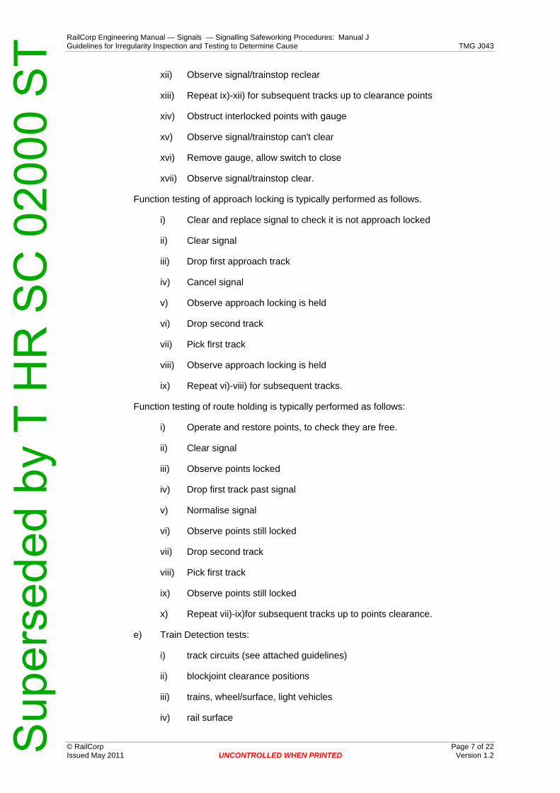
RailCorp Engineering Manual — Signals — Signalling Safeworking Procedures: Manual J Guidelines for Irregularity Inspection and Testing to Determine Cause TMG J043
© RailCorp Page 7 of 22 Issued May 2011 UNCONTROLLED WHEN PRINTED Version 1.2
xii) Observe signal/trainstop reclear
xiii) Repeat ix)-xii) for subsequent tracks up to clearance points
xiv) Obstruct interlocked points with gauge
xv) Observe signal/trainstop can't clear
xvi) Remove gauge, allow switch to close
xvii) Observe signal/trainstop clear.
Function testing of approach locking is typically performed as follows.
i) Clear and replace signal to check it is not approach locked
ii) Clear signal
iii) Drop first approach track
iv) Cancel signal
v) Observe approach locking is held
vi) Drop second track
vii) Pick first track
viii) Observe approach locking is held
ix) Repeat vi)-viii) for subsequent tracks.
Function testing of route holding is typically performed as follows:
i) Operate and restore points, to check they are free.
ii) Clear signal
iii) Observe points locked
iv) Drop first track past signal
v) Normalise signal
vi) Observe points still locked
vii) Drop second track
viii) Pick first track
ix) Observe points still locked
x) Repeat vii)-ix)for subsequent tracks up to points clearance.
e) Train Detection tests:
i) track circuits (see attached guidelines)
ii) blockjoint clearance positions
iii) trains, wheel/surface, light vehicles
iv) rail surface
Sup
erse
ded
by T
HR
SC
020
00 S
T

RailCorp Engineering Manual — Signals — Signalling Safeworking Procedures: Manual J Guidelines for Irregularity Inspection and Testing to Determine Cause TMG J043
© RailCorp Page 8 of 22 Issued May 2011 UNCONTROLLED WHEN PRINTED Version 1.2
f) Electrical Insulation/Isolation inspections and tests:
i) Inspect cable insulation, cable entries, cable clamps, cable troughing, cable joints for signs of damage/deterioration of insulation, water entry, burning,
ii) Inspect cable terminations, crimps, connections for signs of bare metal, wire strands, looseness, arcing, burning,
iii) Inspect insulating surfaces for signs of electrical tracking, water, burning, arcing, metallic dust etc.
iv) Inspect contacts for signs of sustained arcing, sticking, welding etc., and for adequate air gap, proper adjustment, proper clearances.
v) Close circuit, operate function and check for correct voltage across function.
Open circuit by removing fuse and check function de-energises and voltage across function goes to zero (if AC circuit in multicore cable check induced voltage is well below de-energise voltage).
Repeat test but open circuit by removing negative/common terminal instead of fuse.
Maintain other circuits closed and operating normally during tests to detect any leakage current present.
vi) Check earth leakage detectors
vii) Check busbar voltages to earth using voltage-to-earth meters or Fluke meter with 100K ohm shunt. Compare with records.
viii) Check power supplies are isolated from one another
ix) Megger test the circuit to earth and to equipment racks, equipment cases, and cable sheaths where these are insulated from earth.
x) Megger test multicore cables core to core, core to sheath, core to earth, sheath to earth.
Should the investigating Signal Engineer require further megger testing directly between circuits or directly across open contacts, the method of testing needs to be carefully considered as to the disconnection of semi-conductor devices, including power supply units, and the use of temporary bridging around open contacts or around semi-conductor devices removed for the test. The use of temporary bridging must be strictly controlled by the investigating Signal Engineer and bridges must be recorded and recovered immediately after each application.
xi) Hand trace and examine the circuit wiring. If this could disturb suspect wiring it should be the last test of the circuit or if a number of circuits are to be tested all other tests of all relevant circuits should be performed before the wiring is disturbed.
Note:
In the case of internal circuits in a main relay room fitted with earth leakage detection, it may not be necessary to initially insulation test each circuit individually, providing the earth leakage detection is operating
Sup
erse
ded
by T
HR
SC
020
00 S
T

RailCorp Engineering Manual — Signals — Signalling Safeworking Procedures: Manual J Guidelines for Irregularity Inspection and Testing to Determine Cause TMG J043
© RailCorp Page 9 of 22 Issued May 2011 UNCONTROLLED WHEN PRINTED Version 1.2
correctly, and proved to be so by the application of a test earth on each busbar and observing the earth leakage detector drop out.
g) Circuit Test to the Wiring Diagrams:
i) Check equipment for correct type, correct indexing, pin coding etc.
ii) Close circuit, operate function and check for correct voltage across the function, including correct polarity where relevant.
iii) Open and close each fuse, contact and link in turn noting the function de-energise and the voltage reduce to zero
iv) Wire count the complete circuit (s). Null count the terminals on equipment items in the circuit.
v) Prove contacts are in correct adjustment and operate in correspondence with their operating mechanisms.
h) Security Inspections:
i) location locks
ii) signalling equipment locks
i) Signal Inspections:
If the irregularity involves the passing of a signal at stop or allegedly at clear the investigating engineer should inspect the signal sighting and check the following, among other things:
sighting distance; focus; lamp filament; lamp voltage; lens condition; lens colour; lampcase lock; lampcase seal from external light; lampcase internal finish in matt black; possibility of confusion with background lighting; possibility of vegetation, structures or vehicles on other lines affecting line of sight; possibility of confusion with other signals or reading through; possibility of reflected phantom indication; possibility of indication being "washed out" with bright incident light; possibility of power supply interruption etc.
If needed the signal should be observed from the same type of train travelling at the same time of day under the same weather conditions etc.
3 Function Testing Observations Function testing is testing in which the function is operated through its controls to check that it achieves its specified purpose and includes testing that it will not operate from a safe position if any of the required controls are incorrect or missing.
Investigating Signal Engineers should ensure that their observations cover all levels of the operation that they need to check when function testing, viz the trackside apparatus, the local controls and indications, intermediate controls and indications, the central controls and indications and the operator's control console and indicator diagram.
There are a number of levels at which signal equipment may be observed to operate/not operate, for example, in the case of a signal:
a) signal aspects
b) signal UCR relay
Sup
erse
ded
by T
HR
SC
020
00 S
T

RailCorp Engineering Manual — Signals — Signalling Safeworking Procedures: Manual J Guidelines for Irregularity Inspection and Testing to Determine Cause TMG J043
© RailCorp Page 10 of 22 Issued May 2011 UNCONTROLLED WHEN PRINTED Version 1.2
c) signal HR/DR relays
d) signal repeater on diagram
There are a number of levels at which controls may be opened and closed in order to observe the operation/non-operation of signalling equipment, for example, in the case of a track circuits:
a) track circuit rail shunt
b) track circuit relay.
c) track circuit relay contact.
If, for example, a signal repeater is observed to correctly change status when a track relay circuit fuse is removed, this would not in itself include proof that the signal repeater is in correspondence with the signal control relays or the signal aspects, and would not in itself include proof that the specific track circuit relay contact concerned would put the signal to stop when a train occupied the track circuit.
Investigating Signal Engineers are to be aware that through correspondence tests may need to be completed in addition to the interlocking and control function tests (at a particular level) between elements which control or indicate the operation of the trackside apparatus.
4 Examples of Some Tests for Particular Irregularity Incidents
4.1 Interlocked Signal alleged Falsely at Clear or at Less Restrictive aspect.
4.1.1 Interlocking Test
All functions interlocked with the signal (as shown on the Locking Table) are to be proved to be so locked by performing interlocking tests with those functions.
4.1.2 Function Test
The signal is to be proved to correctly return to stop when each controlling track circuit and point detector function is de-energised.
The signal is to be proved to be correctly approach locked. The first approach track to the signal is to be dropped and the signal returned to stop. Then each approach track is to be dropped in turn up to the signal to ensure the approach locking is not released. The approach locking time limit release is also to be checked.
Lamp proving is to be proved to be effective.
The track stick circuit is to be proved to be effective, also any trainstop VCSR circuit.
Aspect sequence is to be checked.
4.1.3 Insulation Testing
The signal light operating circuit and all control and indication circuits for the signal are to be considered for insulation resistance testing.
These include RUR, UCR, LSpR, HR, HDR, DR and ALSR circuits or their equivalents (Relay Interlocking - Reverse relay, NI relay, Control, Caution, Medium, Clear, Approach
Sup
erse
ded
by T
HR
SC
020
00 S
T

RailCorp Engineering Manual — Signals — Signalling Safeworking Procedures: Manual J Guidelines for Irregularity Inspection and Testing to Determine Cause TMG J043
© RailCorp Page 11 of 22 Issued May 2011 UNCONTROLLED WHEN PRINTED Version 1.2
stick etc; Electromechanical Interlocking - N lock, NI lock, LPR, Control etc;) and related repeat relays.
Also included are the signal repeater circuit, and the track stick circuit.
All operating, control, and indication circuits for an associated trainstop are also to be considered.
The controls within the above circuits may also need to be considered for insulation testing eg., detector relays, track relays etc.
4.1.4 Track Shunt Tests
Each track circuit in the approach locking and track control of the signal is to be shunt tested. The track relays and all their track repeat relays are to be observed to correctly operate for these tests, to prove correspondence. As all these relays are unproved, close examination of their operation is required.
4.1.5 Circuit Testing
Where further testing is required, the circuits considered for insulation testing may need to be considered for circuit strap and function testing, wire counting, and bell continuity testing or hand tracing.
4.2 Automatic Signal alleged Falsely at Clear or at Less Restrictive aspect.
4.2.1 Interlocking Test
Not applicable.
4.2.2 Function Test
Each track circuit (and any other function) is to be proved to return the signal to stop.
Lamp proving is to be proved to be effective.
The track stick circuit is to be proved to be effective, also any trainstop VCSR circuit.
Aspect sequence is to be checked.
4.2.3 Insulation Testing
The signal light operating circuit and all control and indicating circuits for the signal are to be considered for insulation resistance testing.
These include:-
LSpR, HR, HDR, DR, circuits or their equivalents.
Also included is the track stick circuit.
All operating, control and indication circuits for an associated trainstop are also to be considered.
The controls within the above circuits may also need to be considered for insulation testing eg. track relays, release switch normal relays etc.
Sup
erse
ded
by T
HR
SC
020
00 S
T

RailCorp Engineering Manual — Signals — Signalling Safeworking Procedures: Manual J Guidelines for Irregularity Inspection and Testing to Determine Cause TMG J043
© RailCorp Page 12 of 22 Issued May 2011 UNCONTROLLED WHEN PRINTED Version 1.2
4.2.4 Track Shunt Tests
Each track circuit in the signal route is to be shunt tested and the track relay and any repeat relays are to be observed to operate correctly and in correspondence.
4.2.5 Circuit Testing
Where further testing is required, the circuits considered for insulation testing may need to be considered for circuit strap and function testing, wire counting, and bell continuity testing or hand tracing.
4.3 Points Run Through, or Operated in Front of Train
4.3.1 Interlocking Test
All functions interlocked with the points (as shown on the locking table) are to be proved to be so locked by performing interlocking tests with those functions.
4.3.2 Function Test
Each track circuit that dead locks the points shall be proved to do so.
Where there is route holding between protecting signals and the points, this route holding is to be tested by clearing the signal and dropping the first track circuit and then restoring the signal. Each track up to the points should then be dropped in turn to ensure the route locking is effective.
Any timed release of route locking is to be checked to be functioning correctly.
4.3.3 Insulation Testing
All points operating, control, and indication circuits are to be considered for insulation resistance testing.
These include NLR/RLR, NWR/RWR, NKR/RKR, NWKR/RWKR, NLKPR/RLKPR, NWAR, RWAR, WZR, WJR, IR and point motor operating circuits, or the equivalents in other interlockings (Relay Interlocking - Normal and Reverse Relays, Lock Relays, Contactors, Route Sticks etc. Electromechanical Interlocking-LPR's, Contactors, N & R locks, NI - RI locks, etc).
4.3.4 Track Shunt Tests
All local track circuits, and all route holding tracks from a protecting signal to the points are to be shunt tested. The track relays and the track repeat relays are to be observed to correctly operate for these tests, to prove correspondence. As all these relays are unproved, close observation of their operation is required.
4.3.5 Circuit Testing
Where further testing is required, the circuits considered for insulation testing may need to be considered for circuit strap and function testing, wire counting, and bell continuity testing or hand tracing.
Sup
erse
ded
by T
HR
SC
020
00 S
T
RailCorp Engineering Manual — Signals — Signalling Safeworking Procedures: Manual J Guidelines for Irregularity Inspection and Testing to Determine Cause TMG J043
© RailCorp Page 13 of 22 Issued May 2011 UNCONTROLLED WHEN PRINTED Version 1.2
5 Guidelines for Testing of Track Circuits in Irregularity Investigations
5.1 Introduction
When a signalling irregularity is reported, it is critical that the testing which follows be completed as quickly as possible, at the same time ensuring that it is sufficiently detailed and comprehensive to identify any possible cause.
The use of a comprehensive checklist as an 'aide-memoire' can ensure that all necessary testing is completed, with minimum wasted effort and time.
This guideline recommends a general series of steps to be followed in investigating an incident believed to involve the false indication of a track circuit as 'clear', while occupied by a train.
Prior to these activities being undertaken, preliminary investigations will have established that there is substantial evidence that an irregularity has in fact occurred, and that it may involve the irregular operation of one or more track circuits.
The procedure's purpose is to check in a logical manner, for anomalies in all parts and operating characteristics of a track circuit.
Caution Where the incident leading to the investigation is of a serious nature, take care to avoid, as far as possible without compromising safety, making any
change which might be considered to alter conditions material to any subsequent investigation.
5.2 Possible Causes
5.2.1 Recent History, Background
Has there been any work carried out recently which might affect the signalling system, or give rise to unusual indications in the course of the work?
Check the recent history of the area concerned, for all activities which might affect the operation of the signalling system. Activities could include routine maintenance, repairs, installation, trackwork etc.
5.2.2 Manipulation
Was the relay held in the energised position by manipulation?
Check the location for signs of entry, the relay for broken seals or other signs of manipulation. Were any persons noticed in or about the relay location at the time of the incident?
If 'yes', record the details, and continue the tests.
5.2.3 Relay Fault
Is there any mechanical defect in the relay which could cause it to remain in an energised position, or for one or more contacts to remain closed with the relay de-energised?
Do a close visual inspection of the relay.
Sup
erse
ded
by T
HR
SC
020
00 S
T

RailCorp Engineering Manual — Signals — Signalling Safeworking Procedures: Manual J Guidelines for Irregularity Inspection and Testing to Determine Cause TMG J043
© RailCorp Page 14 of 22 Issued May 2011 UNCONTROLLED WHEN PRINTED Version 1.2
If an obvious fault is found (for instance, relay still being held up with zero volts applied), have it verified, then try to determine the cause of the mechanical fault without disturbing the relay. If it is not possible to accurately determine the cause of the fault, record all that can be seen, then gently remove the relay, taking the utmost care to retain the faulty condition. Return the relay for a full workshop examination and repair. Replace with a new relay, then carry out a normal comprehensive track circuit test, as done when a relay is replaced in routine maintenance.
If an apparent fault is found, record the details, then continue with this procedure, to identify any other possible cause.
If no definite cause is subsequently found, replace the relay as a precautionary measure, and return the relay for a full workshop examination and repair.
5.2.4 Circuit Error
Is the track circuit, including bonding, wired correctly?
Check that the track circuit is wired according to the circuit book and track insulation plans, and that the drawings themselves are correct.
If an error is found in one or both, record the details, then continue with this procedure, to identify any other possible cause.
After completing the other inspections and tests, make the necessary corrections and then carry out a full test of the track circuit's operation.
5.2.5 Circuit Fault
Is there a fault in the track circuit wiring?
Megger test all track circuit wiring; include tests on relay and feed cables, from each core to earth and to adjacent track circuits' relay and feed cables.
If any faults are found, record the details, and whether they could result in false energisation of the relay. Continue with this procedure, to identify any other possible cause.
After completing the other inspections and tests, return and correct the fault and then carry out a full test of the track circuit's operation.
5.2.6 Adjustment/Sensitivity
Are any track circuit fuses open circuit?
If open-circuit, examine the fuse wire to determine the nature of the failure. Record the details. Retain the defective fuse, and fit a replacement unit.
Is the track circuit incorrectly adjusted, resulting in reduced sensitivity to shunts?
Check all operating voltages. Measure the drop shunt resistance value of the track circuit, at all extremities and at several points evenly spaced along the track circuit. Note the relay control voltage when shunted, for each shunting point.
If any values are out of specified range, record them, and continue the tests.
After completing the other inspections and tests, return and adjust track circuit levels and then carry out a full test of the track circuit's operation.
Sup
erse
ded
by T
HR
SC
020
00 S
T

RailCorp Engineering Manual — Signals — Signalling Safeworking Procedures: Manual J Guidelines for Irregularity Inspection and Testing to Determine Cause TMG J043
© RailCorp Page 15 of 22 Issued May 2011 UNCONTROLLED WHEN PRINTED Version 1.2
5.2.7 False Energisation
5.2.7.1 Extraneous feeds
Is the track relay being energised by current from an external source?
Check polarity reversal to adjacent tracks (on DC, 50Hz and J/S tracks). If any error is found, record the details,
After completing the other inspections and tests, and before final retesting, return and correct any phasing error that was found.
Switch off track feed (O/C fuse to feed set or to feed transformer primary) and check that the residual voltage on the track relay is zero or near zero (less than 0.02 volts for double-element AC relay, or a higher voltage but at adjacent track circuit frequency on jointless track circuit).
On an AC track circuit, also remove the local fuse and check that local and control coil voltages are completely zero.
If the relay residual voltage is not zero, then the track relay is subject to current from an external source which must be identified and corrected.
Check external connections to rails; note particularly the condition of any spark gaps, and record the position of any that are short-circuited. Use a Clancy meter to locate any point where current is entering or leaving the track circuit. Individually clear and replace any extraneous connections found, checking the track relay input each time.
On jointless track, check attenuation of tuned loops between the suspect track and adjacent tracks operating at the same frequency.
In single rail track circuits areas a level of stray signalling current could be expected in the traction rail. Stray current shall not be permitted to cause a residual voltage of greater than 30 percent of the drop away value of the track relay.
On D.C. tracks any residual voltage due to track battery effect must be less then thirty percent of the drop away voltage of the track relay.
5.2.7.2 Circulating Currents in AC and Audio Frequency Track Circuits
Is there a stray circulating current, able to affect the operation of the relay?
Using an Induction meter, measure the currents in opposite rails of the track circuit and the current between the track circuits (eg. in the impedance bond neutral connections on double rail A.C. track circuits or in the traction rail opposite the signalling rail blockjoint in single rail track circuits).
If rail currents are unequal, this indicates the presence of stray alternating current in the rails (In single rail track circuit areas the Clancy meter reading will include traction harmonics in the traction rail and this could account for differences between the signalling rail and the traction rail currents). The source may be the suspect track circuit itself.
Disconnect the power supply to the track feed. Measure the rail currents and the current between the track circuits. Restore the track feed power supply connection.
If these currents dropped to zero, the track circuit itself is the source of the circulating current.
This indicates the presence of a resistance (impedance) unbalance in the track circuit, which can render it prone to false energisation by a stray current. The unbalance may be
Sup
erse
ded
by T
HR
SC
020
00 S
T

RailCorp Engineering Manual — Signals — Signalling Safeworking Procedures: Manual J Guidelines for Irregularity Inspection and Testing to Determine Cause TMG J043
© RailCorp Page 16 of 22 Issued May 2011 UNCONTROLLED WHEN PRINTED Version 1.2
caused by one or more high resistance rail or bond connections, high resistance mechanical joints, broken rails, defective insulated blockjoints, defective impedance bonds or low resistance leakage paths to earth.
Examine the track carefully for open-circuit or high-resistance connections or bonds. High resistance rail connections can be checked by measuring the track circuit voltage drop between the rail connection cable and the head of the rail. Good connections for AC and audio frequency track circuits measure less than a few millivolts AC; any connection that measures more than 10 millivolts, or significantly more than the connections adjacent to it, should be regarded as suspect.
For a conclusive test of rails and impedance bond connections on a double rail track circuit, measure simultaneously the traction currents in both sets of sideleads with high current D.C. tongmeters; the degree to which traction current is unequally shared indicates the amount of resistance unbalance in the track circuit. Individual checking of each side lead in both sets further determines the equality of the connections.
If the source of the circulating current is external, the current between the track circuits will be unchanged when the feed power supply is disconnected and, in balanced double rail track circuits, the rail currents will each equal about half of the neutral current.
Trace the circulating current to its source, and correct the fault that causes it. On any balanced double rail track circuit in the path of the circulating current, the neutral current will be equal to the difference in the currents in the two rails.
5.2.8 Fail to Shunt
If all tests to this stage have identified no cause for the irregular operation of the track, check for conditions leading to a failure of a train or track vehicle to shunt the track.
Was the train involved in the irregularity of short length, and/or consist of very light vehicles?
If the train was one or more light engines only, were they electric or diesel powered?
If it was a light rail vehicle, was it one that had been authorised to work under track block operating conditions, was it travelling at speed?
Inspect the rails of the track circuit, and in particular the rail contact surfaces and surroundings.
Do the wheels appear to adequately clean the rail or do they track only on a narrow width of the rail head.
Is the suspect track circuit itself very short?
Is it infrequently used, or are there long periods without traffic over the track?
Does the rail show signs of recent corrosion on its contact surfaces?
Are there signs of gross contamination on or immediately adjacent to the rail?
These checks may indicate a combination of conditions in which it is likely that all or part of the train could have failed to shunt the track circuit due to the presence of an insulating layer on the rail and/or wheel contact surfaces.
If all other factors have already been eliminated as possible causes, then the final check is to monitor the operation of the track circuit under track and train conditions which reproduce as closely as possible those which existed at the time of the reported irregularity.
Sup
erse
ded
by T
HR
SC
020
00 S
T
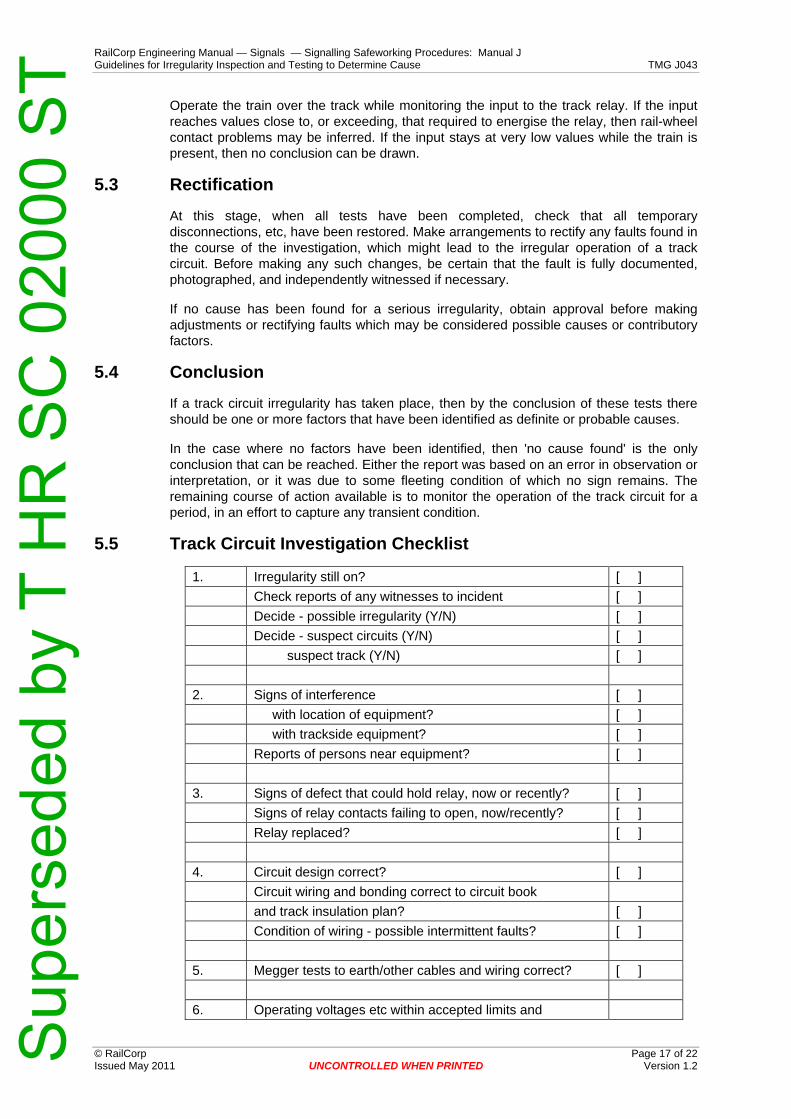
RailCorp Engineering Manual — Signals — Signalling Safeworking Procedures: Manual J Guidelines for Irregularity Inspection and Testing to Determine Cause TMG J043
© RailCorp Page 17 of 22 Issued May 2011 UNCONTROLLED WHEN PRINTED Version 1.2
Operate the train over the track while monitoring the input to the track relay. If the input reaches values close to, or exceeding, that required to energise the relay, then rail-wheel contact problems may be inferred. If the input stays at very low values while the train is present, then no conclusion can be drawn.
5.3 Rectification
At this stage, when all tests have been completed, check that all temporary disconnections, etc, have been restored. Make arrangements to rectify any faults found in the course of the investigation, which might lead to the irregular operation of a track circuit. Before making any such changes, be certain that the fault is fully documented, photographed, and independently witnessed if necessary.
If no cause has been found for a serious irregularity, obtain approval before making adjustments or rectifying faults which may be considered possible causes or contributory factors.
5.4 Conclusion
If a track circuit irregularity has taken place, then by the conclusion of these tests there should be one or more factors that have been identified as definite or probable causes.
In the case where no factors have been identified, then 'no cause found' is the only conclusion that can be reached. Either the report was based on an error in observation or interpretation, or it was due to some fleeting condition of which no sign remains. The remaining course of action available is to monitor the operation of the track circuit for a period, in an effort to capture any transient condition.
5.5 Track Circuit Investigation Checklist
1. Irregularity still on? [ ] Check reports of any witnesses to incident [ ] Decide - possible irregularity (Y/N) [ ] Decide - suspect circuits (Y/N) [ ] suspect track (Y/N) [ ] 2. Signs of interference [ ] with location of equipment? [ ] with trackside equipment? [ ] Reports of persons near equipment? [ ] 3. Signs of defect that could hold relay, now or recently? [ ] Signs of relay contacts failing to open, now/recently? [ ] Relay replaced? [ ] 4. Circuit design correct? [ ] Circuit wiring and bonding correct to circuit book and track insulation plan? [ ] Condition of wiring - possible intermittent faults? [ ] 5. Megger tests to earth/other cables and wiring correct? [ ] 6. Operating voltages etc within accepted limits and
Sup
erse
ded
by T
HR
SC
020
00 S
T

RailCorp Engineering Manual — Signals — Signalling Safeworking Procedures: Manual J Guidelines for Irregularity Inspection and Testing to Determine Cause TMG J043
© RailCorp Page 18 of 22 Issued May 2011 UNCONTROLLED WHEN PRINTED Version 1.2
consistent with history card? [ ] Track drop shunt within specifications? [ ]
7. Relay has 'zero' residual voltage with feed power supply removed? [ ]
Phasing to adjacent tracks correct? [ ] Blockjoints and bonding OK? [ ] Spark gaps in good conditions (V greater than 5.0v)? [ ] No other rail connections [ ] Rail currents balanced and no sudden increase/decrease? [ ] Tuned loop rejection value greater than 10? [ ] Are rail currents unequal? [ ]
Do currents drop to zero with feed power supply removed? [ ]
Check all bonds and sidelead connections OK [ ] Does difference in rail currents equal bond neutral current? [ ] Trace circulating current to source, and correct [ ] 8. Check for train failing to shunt - [ ] Train short [ ] light weight [ ] authorised for track-block operation [ ] Train speed over trainlength prior to incident [ ] powering or coasting? [ ] diesel or electric traction? [ ] Rail contact surfaces clean and polished? [ ] signs of recent oxide film? [ ] signs of heavy contamination? [ ] signs of contaminates at foot of rail? [ ] Track circuit short length? [ ]
6 Irregularities and Wrong Side Failures, Types, Factors and Defects
6.1 Irregularity Type Irregularities which do not result in false proceed or false release.
False proceed signal indication, train ahead.
False proceed signal indication, conflicting route.
False proceed signal indication, points not correctly set and secured.
False warning signal indication, less restrictive.
False line clear indication, block instrument.
Second staff issue, electric train staff instrument.
Sup
erse
ded
by T
HR
SC
020
00 S
T

RailCorp Engineering Manual — Signals — Signalling Safeworking Procedures: Manual J Guidelines for Irregularity Inspection and Testing to Determine Cause TMG J043
© RailCorp Page 19 of 22 Issued May 2011 UNCONTROLLED WHEN PRINTED Version 1.2
Facing points released with train present, loss of approach/route holding locking.
Facing points opening with train present, defective points equipment.
Ground frame irregularly released, train approaching.
Trainstop falsely clear.
Level Crossing protection inoperative.
6.2 Factors
Track Circuit Not Detecting Train
out of adjustment
track relay defective
stray/induced currents
contaminated rail surfaces, light rail vehicles
defective, damaged track circuit equipment
open circuit parallel bonds
incorrect polarity reversal, short circuit blockjoint
Circuit Wiring and Contacts Incorrect/Ineffective
Incorrect
faulty design
faulty installation
Ineffective
coupled/induced currents
leakage currents, defective insulation/isolation
contacts not switching
contacts out of adjustment
Relay falsely energised
electrically held
contacts welded
mechanically held
magnetically held (residual magnetism)
timing short
Points Detection Incorrect/Ineffective
out of adjustment
Sup
erse
ded
by T
HR
SC
020
00 S
T
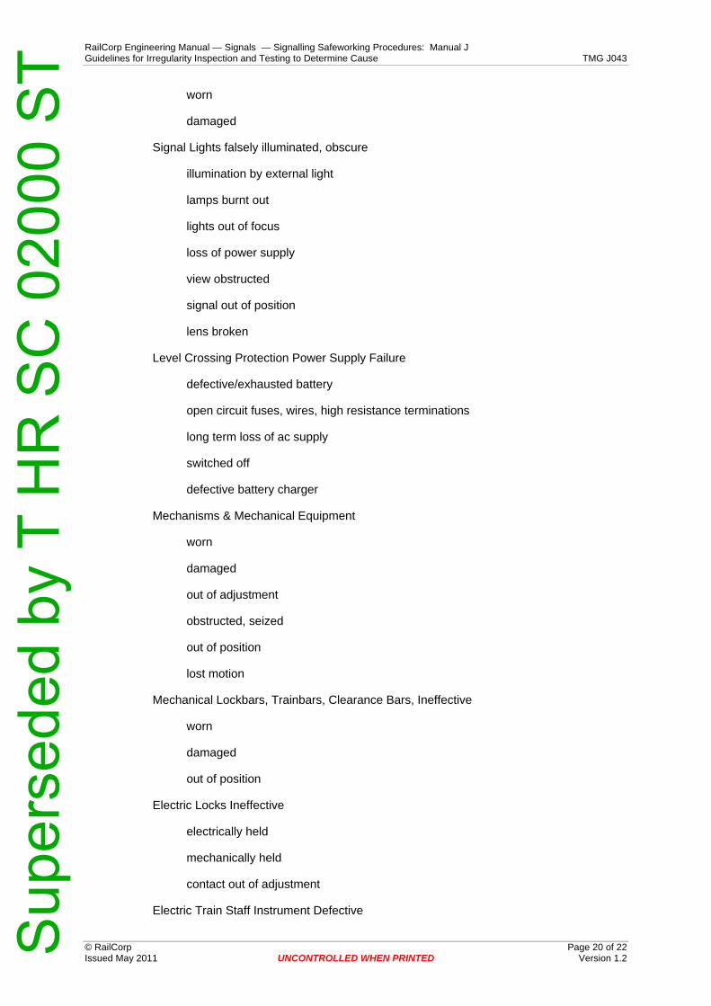
RailCorp Engineering Manual — Signals — Signalling Safeworking Procedures: Manual J Guidelines for Irregularity Inspection and Testing to Determine Cause TMG J043
© RailCorp Page 20 of 22 Issued May 2011 UNCONTROLLED WHEN PRINTED Version 1.2
worn
damaged
Signal Lights falsely illuminated, obscure
illumination by external light
lamps burnt out
lights out of focus
loss of power supply
view obstructed
signal out of position
lens broken
Level Crossing Protection Power Supply Failure
defective/exhausted battery
open circuit fuses, wires, high resistance terminations
long term loss of ac supply
switched off
defective battery charger
Mechanisms & Mechanical Equipment
worn
damaged
out of adjustment
obstructed, seized
out of position
lost motion
Mechanical Lockbars, Trainbars, Clearance Bars, Ineffective
worn
damaged
out of position
Electric Locks Ineffective
electrically held
mechanically held
contact out of adjustment
Electric Train Staff Instrument Defective
Sup
erse
ded
by T
HR
SC
020
00 S
T

RailCorp Engineering Manual — Signals — Signalling Safeworking Procedures: Manual J Guidelines for Irregularity Inspection and Testing to Determine Cause TMG J043
© RailCorp Page 21 of 22 Issued May 2011 UNCONTROLLED WHEN PRINTED Version 1.2
Block Instrument Defective
Trainstop Defective
out of gauge
damaged
obstructed
Mechanical Interlocking Defective
6.3 Defect type
6.3.1 Mechanical Defect
Component/assembly dislocated, deformed, damaged, degraded (physical properties), disintegrated, fractured, fatigued, flooded, obstructed, tight, loose, stuck, corroded, worn, welded, overheated, vibration affected,
Equipment out of adjustment, tolerances exceeded,
Faulty equipment design, manufacture, installation, maintenance,
6.3.2 Optical Defect
Signal lens illuminated by external light
Lens broken
Lens colour change
6.3.3 Electrical Defect
Circuit incorrectly designed
Circuit incorrectly wired
Isolated conducting parts moving into contact
Leakage currents tracking across contaminated/wet insulating surfaces
Leakage currents tracking through defective insulation directly between circuits
Leakage currents to earth through defective arrestors, metallic connections, defective insulation
Electromagnetic induction/capacitive coupling between alternating current circuits.
Direct current arcing across switching contacts
Residual magnetism in magnetic cores
Circuit adjustment incorrect
Contact adjustment incorrect
Contacts welded, struck
Contaminated rail and/or wheel surfaces preventing correct shunting of track circuits, light rail vehicles.
Sup
erse
ded
by T
HR
SC
020
00 S
T
RailCorp Engineering Manual — Signals — Signalling Safeworking Procedures: Manual J Guidelines for Irregularity Inspection and Testing to Determine Cause TMG J043
© RailCorp Page 22 of 22 Issued May 2011 UNCONTROLLED WHEN PRINTED Version 1.2
Interfering harmonics in track circuits from chopper trains, defective substation supplies, parallel H. V. powerlines,
Battery effect on D.C. track circuits
High resistances resulting in circulating currents through connected functions, track circuits etc.
Insulated blockjoint failure and track circuit polarities not reversed.
Open circuit parallel bonds in a track circuit
Loss of power supply to Level Xing lights (open circuit fuse, exhausted/defective battery, defective battery charger, high resistance/broken connections/wires).
Faulty equipment design, manufacture, installation
Variation in properties of timing circuit components
6.3.4 Damage
Due to power surges, lightning, fire, flood etc
Due to construction, maintenance activity,
Due to accidents
Vandalism
Sabotage
6.3.5 Personnel Defect
Design checking deficient
Inspection and testing incorrectly performed
Emergency releases incorrectly given
Work wrongly performed, procedures not followed, substandard
Signal lens door left open allowing external light to illuminate lens.
Level crossing test switch left turned on, or emergency switch left turned off.
Accidental damage, interference
6.3.6 Management Defect
Faulty or deficient standards
Faulty or deficient procedures
Faulty or deficient training, accreditation
Faulty or deficient supervision, quality control
Sup
erse
ded
by T
HR
SC
020
00 S
T
RailCorp Engineering Manual — Signals — Signalling Safeworking Procedures: Manual J General Signalling Maintenance Management, Administration and Supervision Responsibilities TMG J044
© RailCorp Page 1 of 6 Issued May 2010 UNCONTROLLED WHEN PRINTED Version 1.1
TMG J044
GENERAL SIGNALLING MAINTENANCE MANAGEMENT,
ADMINISTRATION AND SUPERVISION RESPONSIBILITIES
Version 1.1
Issued May 2010
Document control
Version Date Summary of change 1.0 September 2005 Replaced SC 00 52 00 44 SI General Signalling Maintenance
Management, Administration and Supervision Responsibilities. 1.1 May 2010 Application of TMA 400 format
Contents 1 Introduction .............................................................................................................................2
1.1 General Responsibilities............................................................................................2 1.2 Duties.........................................................................................................................2
Sup
erse
ded
by T
HR
SC
020
00 S
T

RailCorp Engineering Manual — Signals — Signalling Safeworking Procedures: Manual J General Signalling Maintenance Management, Administration and Supervision Responsibilities TMG J044
© RailCorp Page 2 of 6 Issued May 2010 UNCONTROLLED WHEN PRINTED Version 1.1
1 Introduction This document sets out general signalling maintenance management, administration and supervision responsibilities to be covered. The responsibilities and authority for specific positions will be determined by RailCorp and Signalling Standards and as set out in particular position descriptions and duty statements.
1.1 General Responsibilities
Responsibility for the safe, reliable and efficient day-to-day running of the maintenance area including the maintenance, installation and renewal of all signalling and nominated communications systems and equipment thereon.
Responsibility for the supervision, welfare, safety and discipline of subordinate personnel. Responsibility for appropriate environmental protection from signalling equipment and activities on the maintenance area.
Responsibility for maintaining an up to date Asset Register of signalling equipment on the maintenance area.
1.2 Duties
The activities associated with the responsibilities listed below shall be assigned to suitably competent and accredited staff, as applicable.
The responsibilities shall include:
a) The planning and control of a system of programmed maintenance and renewals and regular testing and inspection of systems and equipment ensuring that the specified frequencies, laid down programmes, standards and practices are adhered to by all staff involved
b) The supervision, welfare, safety, training and discipline of subordinate personnel.
c) Compliance with OH & S Act requirements relative to maintenance personnel and activity personnel.
d) Compliance with Environment Protection requirements relative to the maintenance area.
e) In emergency situations, additional responsibility on the person’s own judgement, in the best interest of the public and RailCorp and in accordance with stipulated procedures.
f) Giving immediate attention to any report of a signalling or level crossing irregularity, derailment or accident, and carrying out a thorough examination to determine and rectify the cause. Assessing the risk of such an irregularity being repeated or occurring elsewhere and following up with actions to prevent such an occurrence. Responsibility for the proper investigation of irregularities and the certification of the signalling as safe to be restored to use.
g) Performing inspections to:
primarily
Sup
erse
ded
by T
HR
SC
020
00 S
T
RailCorp Engineering Manual — Signals — Signalling Safeworking Procedures: Manual J General Signalling Maintenance Management, Administration and Supervision Responsibilities TMG J044
© RailCorp Page 3 of 6 Issued May 2010 UNCONTROLLED WHEN PRINTED Version 1.1
i) monitor the condition of the equipment throughout the maintenance area in order to determine priority based programs and budgets for renewal, repair or rehabilitation.
ii) monitor the standard of maintenance throughout the maintenance area in order to direct any required corrective actions and to plan for improvement.
iii) monitor the level of compliance throughout the maintenance area with required procedures and practices, special instructions, etc. in order to direct any required corrective actions and/or recommend improvements to the procedures etc.
and secondly
iv) to monitor the cost-effectiveness of maintenance in order to direct any required corrective actions and to plan for improvements.
v) to monitor the efficiency and effectiveness of the signalling system in meeting the operational requirements in order to correct deficiencies and propose improvements.
vi) to communicate directly with staff in their work environment and to give them the opportunity to directly raise issues and receive feed back on matters affecting them.
vii) to communicate directly with local operations and other discipline staff who are serviced by or provide services to the signalling discipline.
h) The preparation and approval of estimates for maintenance and renewal work for recommendation to controlling officers for inclusion in the annual budget, ensuring the material requirements are standard stores items where possible and where plant or other discipline services are required that the necessary costs are included. The control of expenditure to meet budget allocations and maintenance requirements. The approval and control of overtime for subordinate personnel.
i) Organising and/or controlling a program of planned renewals and new works to ensure that the authorised works are executed within the specified authority by the effective use of labour, materials and plant, by scheduling the work effectively, progressing the work, monitoring expenditure and bringing to the immediate attention of controlling officers any changes which may result in over spending.
j) Identifying renewal or modification requirements and inputting to and reviewing tender specifications prepared by project groups for new or altered works affecting the maintenance area; liaison and co-ordination with the project group during the project; preparation of defect lists and acceptance of the completed signalling work.
k) Planning and controlling the allotted activities of subordinates, ensuring all maintenance personnel conform to the safeworking procedures, standards of discipline, and carry out established procedures correctly, and preparing and maintaining appropriate staff duty statements.
l) Being familiar with the maintenance area and the systems, equipment and all the maintenance procedures relative thereto, and ensuring that these procedures are properly carried out.
Sup
erse
ded
by T
HR
SC
020
00 S
T

RailCorp Engineering Manual — Signals — Signalling Safeworking Procedures: Manual J General Signalling Maintenance Management, Administration and Supervision Responsibilities TMG J044
© RailCorp Page 4 of 6 Issued May 2010 UNCONTROLLED WHEN PRINTED Version 1.1
Controlling this by a system of reports and inspections and by directly observing staff performing duties on safety related equipment so that equipment and systems are properly maintained, installed and kept in a satisfactory condition.
m) Organising the development and training of maintenance staff including the examination of staff for competency, interviewing staff and trainees and recommending or approving appointment. Participating on staff examination boards, in mentor systems and counselling sessions
n) Ensuring staff are issued with the proper documentation relevant to the performance of their duties and that this is kept updated. Controlling this with an appropriate document control system and by carrying out audits. Ensuring that important messages in new or changed documentation are communicated to and understood by all staff who need to know through discussion with their supervising officers.
o) A constant review of work practices to improve safety, reliability and economy.
p) Through effective labour management and in conjunction with other staff, proposing area manning revisions including the approval of maintenance and installation work schedules. Seeking opportunities to reduce costs and authorising overtime for work which cannot be performed during normal working hours. Making relief arrangements for the supervisors and maintenance staff and, in particular rosters, for emergencies. With the support of controlling officers contributing to the high morale and good efficiency among all subordinate personnel.
q) Paying particular attention to all equipment failures with the objective of:
i) ascertaining if there was there any undue delay in rectifying the fault.
ii) determining the cause of the fault and any action necessary to prevent a recurrence.
iii) identifying any trend or pattern of repetitive faults.
iv) reducing the incidence of failures, and making recommendations to controlling officers for improvements in the design, maintenance, servicing or repair of the apparatus or equipment in question.
r) Maintaining a high standard of "housekeeping" including but not limited to, a regular survey of
i) safety equipment and clothing, ladders and safety belts.
ii) tools, plant and equipment.
iii) meters and test equipment.
iv) justified spare material.
v) depots and work areas for cleanliness and tidy appearance.
s) The clean up of material released and unserviceable and its appropriate disposal.
t) Keeping a specific record of all temporary repairs made and ensuring that permanent repairs are carried out without undue delay.
Sup
erse
ded
by T
HR
SC
020
00 S
T

RailCorp Engineering Manual — Signals — Signalling Safeworking Procedures: Manual J General Signalling Maintenance Management, Administration and Supervision Responsibilities TMG J044
© RailCorp Page 5 of 6 Issued May 2010 UNCONTROLLED WHEN PRINTED Version 1.1
u) Identifying and maintaining a register of sections of line which are likely to have rust build up and cause loss of train detection. Ensuring that the potential for this is minimised and that if it is likely to occur it will be detected and protected against. Being alert for changes in the type, frequency and tonnage of traffic over the lines.
v) Whenever a complaint has been received concerning the focusing of a signal nominating a competent representative to inspect the signal reported and to have it adjusted accordingly.
w) When there has been a change of wiring or circuits on any vital signalling controls ensuring that the new work is properly tested by suitably competent persons before it is commissioned into service.
x) Maintenance of an asset register of signalling equipment on the maintenance area.
y) Maintaining a register of depots and maintenance personnel authorised to carry out workshop type repairs and overhauls on vital signalling equipment.
z) Maintaining maintenance records of maintenance support equipment, tools, vehicles and plant requiring maintenance, including calibration.
aa) Liaison with the officers of other engineering and operating disciplines on the maintenance area
bb) Arranging as necessary and/or attending communication and co-ordination meetings with other disciplines, other staff and internal and external parties as appropriate to ensure good co-operation, effective planning and the application of appropriate standards and procedures. Preparing agendas and minutes, as required.
cc) In conjunction with other disciplines, if appropriate, making arrangements for track possessions, the requisitioning of plant or material which may be necessary, and the transport of staff to work sites.
dd) Determining methods and procedures for putting into practice fire precautions in the accommodation allotted to depots, in equipment rooms, stores, premises and for line side equipment. The periodical inspection of plant and equipment to eliminate avoidable hazards and accidents. Providing for safe custody of RailCorp property including materials, machines and small tools.
ee) Administering the maintenance area, its assets and resources, in accordance with the approved policies and procedures.
ff) Preparing returns, assessments, and reports, as required by controlling officers, relating to the current state of affairs on the maintenance area.
gg) Investigating third party proposals, as required, for their possible effect on the existing signalling system.
Sup
erse
ded
by T
HR
SC
020
00 S
T

RailCorp Engineering Manual — Signals — Signalling Safeworking Procedures: Manual J General Signalling Maintenance Management, Administration and Supervision Responsibilities TMG J044
© RailCorp Page 6 of 6 Issued May 2010 UNCONTROLLED WHEN PRINTED Version 1.1
This page has been intentionally left blank
Sup
erse
ded
by T
HR
SC
020
00 S
T

RailCorp Engineering Manual — Signals — Signalling Safeworking Procedures: Manual J Surveillance Inspections TMG J045
© RailCorp Page 1 of 4 Issued April 2013 UNCONTROLLED WHEN PRINTED Version 1.2
TMG J045
SURVEILLANCE INSPECTIONS
Version 1.2
Issued April 2013
Document control
Version Date Summary of change 1.0 September 2005 Replaced SC 00 52 00 45 SI Surveillance Inspections. 1.1 May 2010 Application of TMA 400 format 1.2 April 2013 Updated requirements and frequency of surveillance inspections
Added paragraph titles to identify requirements
Contents 1 Introduction .............................................................................................................................2 2 Objectives of Surveillance Inspections ................................................................................2 3 Scheduling & Conducting Surveillance Inspections...........................................................2 4 Notes of Inspection & Action Requirements........................................................................3 5 Other Specific Signal Engineer Inspections and Tests ......................................................3
Sup
erse
ded
by T
HR
SC
020
00 S
T

RailCorp Engineering Manual — Signals — Signalling Safeworking Procedures: Manual J Surveillance Inspections TMG J045
© RailCorp Page 2 of 4 Issued April 2013 UNCONTROLLED WHEN PRINTED Version 1.2
1 Introduction Surveillance inspections by experienced Maintenance Signalling Engineers form part of the regime for assuring the safety integrity and reliability of the signalling system.
2 Objectives of Surveillance Inspections The intention of surveillance inspections is to meet seven key objectives as listed below. There are three primary objectives which are directed at the safety, reliability and technical capability of signalling, and four secondary objectives which contribute towards the efficiency and sustainability of signalling, and provides for effective stakeholder relations and continual improvement.
Primary Objectives: a) Monitor the standard of maintenance throughout the maintenance area in order
to direct any required corrective actions (which may be directed at the asset or the maintainer's technical capability), and to plan for improvement.
b) Monitor the condition of signalling assets throughout the maintenance area in order to determine priority based programs for repair, renewal, or redesign.
c) Monitor the level of compliance throughout the maintenance area with relevant procedures and practices, technical maintenance plans, engineering instructions, etc, in order to direct any required corrective actions and/or recommendations for improvement to the procedures, etc.
Secondary Objectives: d) Monitor the efficiency and effectiveness of maintenance in order to direct any
required corrective actions and to plan for improvements.
e) Monitor the efficiency and effectiveness of the signalling system in meeting the operational requirements in order to correct deficiencies and propose improvements.
f) Communicate directly with maintenance personnel in their work environment and to give them the opportunity to directly raise issues and receive feed back on matters affecting them.
g) Communicate directly with local operations and other stakeholders who are serviced by or provide services to the signalling discipline.
3 Scheduling & Conducting Surveillance Inspections Surveillance inspections shall be performed by experienced Maintenance Signal Engineers and be scheduled on an annual basis. The scheduling shall be such that an adequate inspection sample is conducted of no less than 20% of the maintenance district, eventually covering the whole area over a five year period.
While it may not be practical for surveillance inspections to cover every single item of equipment on the maintenance district every five years, the scope of inspections and observations shall adequately achieve the seven objectives listed above. The inspections shall include in-depth examination and tests of judiciously selected items and activities from selected areas of aging or brand new installations, or where signalling equipment is out of the way or awkward to access or maintain, or where it may be missed or not performed well by inexperienced signalling personnel, or has a poor performance history. The inspections shall include checks of facing point locks and detector adjustments, track circuit history card records and level crossing test records.
Sup
erse
ded
by T
HR
SC
020
00 S
T

RailCorp Engineering Manual — Signals — Signalling Safeworking Procedures: Manual J Surveillance Inspections TMG J045
© RailCorp Page 3 of 4 Issued April 2013 UNCONTROLLED WHEN PRINTED Version 1.2
It is important that dedicated surveillance inspections are scheduled annually and are conducted by experienced Signal Engineers. However, there are many other opportunities where Maintenance Signal Engineers can capitalise on fulfilling the scope of surveillance inspections. These opportunities may include: mechanical interlocking testing, signal sighting inspections, level crossing inspections, site integrity meetings, practical completion inspections, failure follow-up investigations, irregularity investigations, asset condition inspections and general observations of work being performed by signalling personnel.
4 Notes of Inspection & Action Requirements The surveillance inspections shall be recorded and the results of the inspections shall be documented and retained on file. The documentation shall provide objective evidence of the performance of the inspection. Documented outcomes could be ‘Notes of Inspection’ issued with action requirements (which should be priority based and time scaled where appropriate), training programmes to improve competency, arrangements for increased supervision, adjustments to rosters, local instructions to correct deficiencies, renewal programs, recommendations for changes to procedures, etc.
A defect management system such as Teams III or similar shall be used to manage defects raised for corrective action, and to prioritise and program work to accepted timeframes.
Surveillance inspections provide a vital opportunity to assess a person's competence and compliance with signalling procedures. The most effective way to know if people understand their work and ensure they comply is to observe them doing the work or otherwise by asking them to demonstrate how they would do the work. Signalling Maintenance Engineers shall take every opportunity to be satisfied with the competence and compliance of signalling persons (including supervisors) for work performed within their area of responsibility.
Signalling Maintenance Engineers shall record occasions where they have directly observed personnel performing signalling related tasks. These shall include safety critical and safety significant tasks.
The surveillance inspections shall also monitor environmental safety aspects.
5 Other Specific Signal Engineer Inspections and Tests In addition to the surveillance inspections, there are a number of other specifically nominated inspections and tests required to be carried out by the Maintenance Signal Engineer.
These inspections and tests are:
a) Mechanical Locking/Interlocking tests, conducted every two years (TMG J022).
b) Relay Interlocking tests (where required), conducted every five years (TMG J022).
c) Active Level Crossing Protection inspections and tests, conducted at frequencies stated in TMG J036.
d) Electric Staff Instrument inspections and tests, conducted every two years (TMG J033).
e) Signal Sighting (front of train) inspection, conducted every 6 or 12 months in accordance with TMG J031.
Sup
erse
ded
by T
HR
SC
020
00 S
T

RailCorp Engineering Manual — Signals — Signalling Safeworking Procedures: Manual J Surveillance Inspections TMG J045
© RailCorp Page 4 of 4 Issued April 2013 UNCONTROLLED WHEN PRINTED Version 1.2
This page has been intentionally left blank
Sup
erse
ded
by T
HR
SC
020
00 S
T

RailCorp Engineering Manual — Signals — Signalling Safeworking Procedures: Manual J Guidelines for the Safe Use of Temporary Recording, Monitoring and Logging Equipment on Signalling Systems TMG J046
© RailCorp Page 1 of 6 Issued May 2010 UNCONTROLLED WHEN PRINTED Version 1.1
TMG J046
GUIDELINES FOR THE SAFE USE OF TEMPORARY RECORDING,
MONITORING AND LOGGING EQUIPMENT ON SIGNALLING
SYSTEMS
Version 1.1
Issued May 2010
Document control
Version Date Summary of change 1.0 September 2005 Replaced SC 00 52 00 46 Guidelines for the Safe Use of
Temporary Recording, Monitoring and Logging Equipment on Signalling Systems.
1.1 May 2010 Application of TMA 400 format
Contents 1 Introduction .............................................................................................................................2 2 Equipment Selection...............................................................................................................2
2.1 General ......................................................................................................................2 2.2 Input Isolation ............................................................................................................2 2.3 Input Impedance ........................................................................................................3
3 Equipment Installation............................................................................................................3 3.1 Wiring Standards .......................................................................................................3 3.2 Connections and Terminations..................................................................................4
4 Special Circumstances...........................................................................................................4 4.1 Track Circuits.............................................................................................................4 4.2 CBI Interface Circuitry................................................................................................4 4.3 Current Measurement................................................................................................4 4.4 Test Lamps ................................................................................................................5
5 Usage and Maintenance .........................................................................................................5
Sup
erse
ded
by T
HR
SC
020
00 S
T

RailCorp Engineering Manual — Signals — Signalling Safeworking Procedures: Manual J Guidelines for the Safe Use of Temporary Recording, Monitoring and Logging Equipment on Signalling Systems TMG J046
© RailCorp Page 2 of 6 Issued May 2010 UNCONTROLLED WHEN PRINTED Version 1.1
1 Introduction When installing and using any type of recording, monitoring and logging equipment (herein known recording equipment), it is imperative that the signalling systems’ safety, integrity, reliability and availability are maintained at all times.
Reasons for connecting this type of equipment to the signalling system include:
a) fault finding and identification of intermittent failures
b) tracking of high resistance relay contacts
c) short term logging/counting of relay operations
d) track sequencing
The types of equipment that this document applies to include:
a) Chart Recorders
b) Logic Analysers
c) Event Recorders
d) Oscilloscopes
e) PC Based recording/monitoring equipment
2 Equipment Selection 2.1 General
All equipment that is intended for monitoring, recording or logging of signalling circuits must have been approved for use by the Principal Engineer Signalling Technology.
When selecting recording equipment for connection to the signalling system, the requirements outlined below must be adhered to.
If recording equipment is required to be used that does not meet these requirements, or if it is unknown if the requirements are met, then approved third party isolation and/or signal conditioning devices may be used to interface the equipment to the signalling system.
2.2 Input Isolation
The equipment must not allow cross coupling of signalling circuits through common negative or earth returns. This means that each input to the monitoring equipment must meet or exceed following galvanic isolation requirements:
• 1000 Vpeak input channel to device power supply isolation • 1000 Vpeak input channel to earth isolation • 1000 Vpeak input channel to output isolation • 1000 Vpeak input channel to input channel isolation
The device that provides the electrical isolation shall not fail under any conditions in a manner that provides an electrical connection of less than 2 megohms at 500 volts between the signalling circuit and the indication circuit.
Sup
erse
ded
by T
HR
SC
020
00 S
T
RailCorp Engineering Manual — Signals — Signalling Safeworking Procedures: Manual J Guidelines for the Safe Use of Temporary Recording, Monitoring and Logging Equipment on Signalling Systems TMG J046
© RailCorp Page 3 of 6 Issued May 2010 UNCONTROLLED WHEN PRINTED Version 1.1
2.3 Input Impedance
For direct connection to signalling circuits for voltage type measurements, a 500 volt rated resistor shall be provided in each leg of the input circuit of the monitoring device. The two resistors shall have the same value. The value of the resistors shall be such that when one of the resistors and any other internal active component of the recording device is shorted out, the leakage current drawn is less than that which is required to maintain energised the relay of the signalling circuit being monitored.
The table below lists typical values for various signalling circuits.
Signalling Circuit Maximum Allowable Leakage Current 12 Volt DC 8 milliamperes DC 50 Volt DC 5 milliamperes DC 120 Volt AC 4 milliamperes AC
3 Equipment Installation Before any installation work is commenced, a complete circuit diagram of the recording equipment connections (both power and I/O) must be drawn up and approved for use by the Maintenance Signal Engineer. This approval shall remain valid for a maximum period of four weeks before it expires.
If there is a requirement to still have the recording equipment connected after this time, then a review of the original failure conditions and an assessment of the investigation procedures is to be made before any further approvals are given.
To ensure that the integrity of signalling system is not compromised with the connection of the recording equipment, all wiring to the recording equipment must be independently checked for correct installation. Assurance must also be made that no signalling functions are by-passed by the recording equipment and its wiring.
Two marked up copies of the affected signalling circuits must be made. One copy is to be left on site and the second copy left at the Maintenance Signal Engineer’s office. These circuits are to be removed from site when the recording equipment is disconnected and removed.
3.1 Wiring Standards
Wiring to the monitoring equipment is to be done to at least to the same standard as that of vital stage work wiring. The wire used must have a minimum insulation rating of 0.6/1kV and temperature rating of V75.
At all times, there is to be minimal disruption to the existing signalling circuit wiring.
In general, the wiring shall be a highly visible colour and shall contrast sufficiently so that it cannot be mistaken for existing wiring. More importantly, it shall not be black in colour nor shall it be of the same colour as any existing or planned future stage work wiring for that site.
All recording equipment power supply circuits and wiring to voltage free contacts from signalling power supplies are to be protected with a suitably rated fuse to no more than 4 amperes.
Sup
erse
ded
by T
HR
SC
020
00 S
T

RailCorp Engineering Manual — Signals — Signalling Safeworking Procedures: Manual J Guidelines for the Safe Use of Temporary Recording, Monitoring and Logging Equipment on Signalling Systems TMG J046
© RailCorp Page 4 of 6 Issued May 2010 UNCONTROLLED WHEN PRINTED Version 1.1
3.2 Connections and Terminations
If the person is to remain in attendance 100% of the time then temporary connections to the signalling circuits are permitted using recording equipment approved for such temporary connection (eg. Fluke Meter probes on the back of a miniature plug-in relay).
For installations where the recording equipment is to be left unattended, all wiring and connections shall be properly identified, lugged and terminated. If connections cannot be terminated by any standard means or if it is required to tap into a signalling circuit where no spare connection is available, then the proposed method of connection shall be approved before hand by the Maintenance Signal Engineer.
An approved method for temporarily connecting recording equipment leads to existing wiring in the back of BRB miniature plug-in relays is by the insertion of wire that is crimped with a Q-style crimp which has had the locking loop and locating tag cut off. Once placed in the back of the relay, the temporary wiring is then to be securely fastened with a cable tie or other similar means to the adjacent wiring harness.
Alligator clips, banana plugs or other types of probes intended for temporary unattended connections or that could become dislodged are not permitted.
The temporary wire must be clearly labelled with the number of the relay and the contact to which it is connected
4 Special Circumstances The special circumstances listed below have been identified as a result of specific cases that have arisen in the past. These cases are by no means the only ones that this document can be applied to. If a need or situation arises that is not clearly covered by this document, then further clarification is to be sought from the Principal Engineer Signalling Technology.
4.1 Track Circuits
Under no circumstances will the feed/transmitter and the relay/receiver of the same track circuit be fed into two separate channels of the same recording device.
This stipulation is to prevent the possibility of electrically bypassing the presence of a train on a track circuit and applies even if all other isolation requirements mentioned above are adhered to.
4.2 CBI Interface Circuitry
Special consideration needs to be made when wiring to CBI interface circuitry. The wiring shall not allow for the induction of electrical noise onto sensitive CBI inputs.
Independent or duplicated data busses and communication channels must not be cross-coupled through the recording device’s signal channel returns or via any earthing connections.
4.3 Current Measurement
Alterations to existing wiring, for the purpose of inserting current shunts are not permitted for measuring current in signalling circuits. Insertion of a shunt by plugging in across an existing disconnection link (eg. Klippon SAKC10) is permissible.
Sup
erse
ded
by T
HR
SC
020
00 S
T

RailCorp Engineering Manual — Signals — Signalling Safeworking Procedures: Manual J Guidelines for the Safe Use of Temporary Recording, Monitoring and Logging Equipment on Signalling Systems TMG J046
© RailCorp Page 5 of 6 Issued May 2010 UNCONTROLLED WHEN PRINTED Version 1.1
The disconnection and reconnection of a wire from a terminal for the purposes of passing that wire through a Hall Effect type transducer or similar device is permissible if carried out by suitably qualified staff.
4.4 Test Lamps
Under no circumstances shall a Test Lamp be used on signalling circuits. The input impedance of the lamp is too low and can cause wrong-side failures by false feeding or bridging out vital logic circuits if used incorrectly.
5 Usage and Maintenance Regular weekly maintenance visits must be carried out on installed recording equipment. Maintenance tasks shall include, but not be limited to the following:
a) confirmation of the integrity of the wiring, connections and terminations of the recording equipment
b) inspection of recording equipment to ensure continued correct operation
c) downloading or extraction of any stored log information (if required)
Sup
erse
ded
by T
HR
SC
020
00 S
T

RailCorp Engineering Manual — Signals — Signalling Safeworking Procedures: Manual J Guidelines for the Safe Use of Temporary Recording, Monitoring and Logging Equipment on Signalling Systems TMG J046
© RailCorp Page 6 of 6 Issued May 2010 UNCONTROLLED WHEN PRINTED Version 1.1
This page has been intentionally left blank
Sup
erse
ded
by T
HR
SC
020
00 S
T

RailCorp Engineering Manual — Signals — Signalling Safeworking Procedures: Manual J Calibration of Tools and Instruments for Signalling Applications
© RailCorp Page 1 of 8 Issued June 2013 UNCONTROLLED WHEN PRINTED
TMG J047
CALIBRATION OF TOOLS AND INSTRUMENTS FOR SIGNALLING
APPLICATIONS Version 1.5
Issued June 2013
Document control
Version Date Summary of change Replaced SC 00 52 00 47 Calibration of Tools and Instruments for
Signalling Applications 1.1 05/06/2007 Calibration frequency adjusted to ‘before use’ for Points Gauge 1.2 07/08/2007 Nominated calibration frequency for TFA / SFTM & calibration
requirements for meter functions on clamp meters 1.3 July 2009 Reference SMS in General Requirements and correct trainstop gauge
calibration accuracy 1.4 May 2010 Application of TMA 400 format
1.5 June 2013 Calibration requirements reviewed. Calibration period of multimeters changed to 3 years from 2 years for approved meters based on historical performance and calibration data analysis; Updated Table
Contents 1 Introduction .............................................................................................................................2 2 Applicable Documents ...........................................................................................................2 3 Notes on Calibration...............................................................................................................2 4 Calibration Standard/Specification .......................................................................................2 5 Extended Calibration Intervals ..............................................................................................2 6 Equipment Failing Manufacturer’s Calibration Specification.............................................3 7 Signals Calibration Requirements ........................................................................................4
Sup
erse
ded
by T
HR
SC
020
00 S
T

RailCorp Engineering Manual — Signals — Signalling Safeworking Procedures: Manual J Calibration of Tools and Instruments for Signalling Applications
© RailCorp Page 2 of 8 Issued June 2013 UNCONTROLLED WHEN PRINTED
1 Introduction This document describes the calibration requirements of tools and test equipment used in the maintenance, testing, installation and commissioning of signalling equipment on the RailCorp network. The following applicable documents are referred to and these documents take precedence in case of any conflict arises.
2 Applicable Documents AS/NZS ISO 10012:2004: Measurement management systems- Requirements for
measurements processes and measuring equipment.
RailCorp SMS-16-SR-0057: Workplace health & safety inspection
BMS-033-PR-002: Control of monitoring and measuring equipment.
SMS-16-TP-0229: Calibrate inspection, testing and monitoring equipment
3 Notes on Calibration Where a particular item of equipment or test application is not listed in the following table, it is to be referred to the Chief Engineer Signals and Control Systems for determination, and any required action that may arise from such determination. Under no circumstances the equipment is to be use on operational signalling equipment/systems until approval has been obtained for its use. Calibration requirements are related to specific tasks being performed. An instrument used for multiple applications needs to be calibrated only to the highest standard required, and only on the measurement ranges applicable. RailCorp requirements regarding the maintenance, inspection, testing, calibrating and monitoring of RailCorp work practices, plant, equipment and workplaces are provided in the SMS document SMS-16-SR-0057 “Inspection and Testing”. Calibration of test equipment used for signalling applications is to be carried out at a minimum to the frequency and accuracy shown in the table on the following pages. Where a manufacturer guarantees that an instrument will exceed the accuracy stated in the following table without recalibration, for the life of the instrument or for longer intervals than stated, then the calibration frequency may be amended accordingly.
4 Calibration Standard/Specification Test equipment is to be calibrated to manufacturer’s specification, unless specified otherwise in table below. A minimum accuracy for RailCorp application is provided to cater for the typical use in signalling applications which generally can tolerate a wider accuracy range without any risk of signalling operational reliability and integrity
5 Extended Calibration Intervals Calibration intervals for approved test equipment have been extended from the equipment manufacturer’s recommendations. This has been determined by analysis of historical records of calibration and adjustment requirements. These extended intervals are only applicable for the approved test equipment as listed.
Sup
erse
ded
by T
HR
SC
020
00 S
T
RailCorp Engineering Manual — Signals — Signalling Safeworking Procedures: Manual J Calibration of Tools and Instruments for Signalling Applications
© RailCorp Page 3 of 8 Issued June 2013 UNCONTROLLED WHEN PRINTED
6 Equipment Failing Manufacturer’s Calibration Specification Test equipment is calibrated to manufacturer's specification as detailed in the calibration frequency in Table below. When test equipment fails a scheduled calibration to the manufacturer's specification a detailed report is to be produced listing the specific functions and range which failed with the tolerance shown and the measured variation to the tolerance. The test equipment owner is to review the variation and assess against the Minimum accuracy for RailCorp application. Where the test equipment is within the Minimum accuracy for RailCorp application no further action is required other than the test equipment is to be readjusted and recalibrated to the manufacturer's specification and new calibration certificate issued. When test equipment has failed a calibration to the manufacturer's specification and the variation is beyond the Minimum accuracy for RailCorp application, the asset owner must assess whether a retesting of equipment certified with this test equipment is necessary. This determination should be conducted with consultation to signalling engineering staff to ensure any signalling operational risks are correctly addressed.
Sup
erse
ded
by T
HR
SC
020
00 S
T
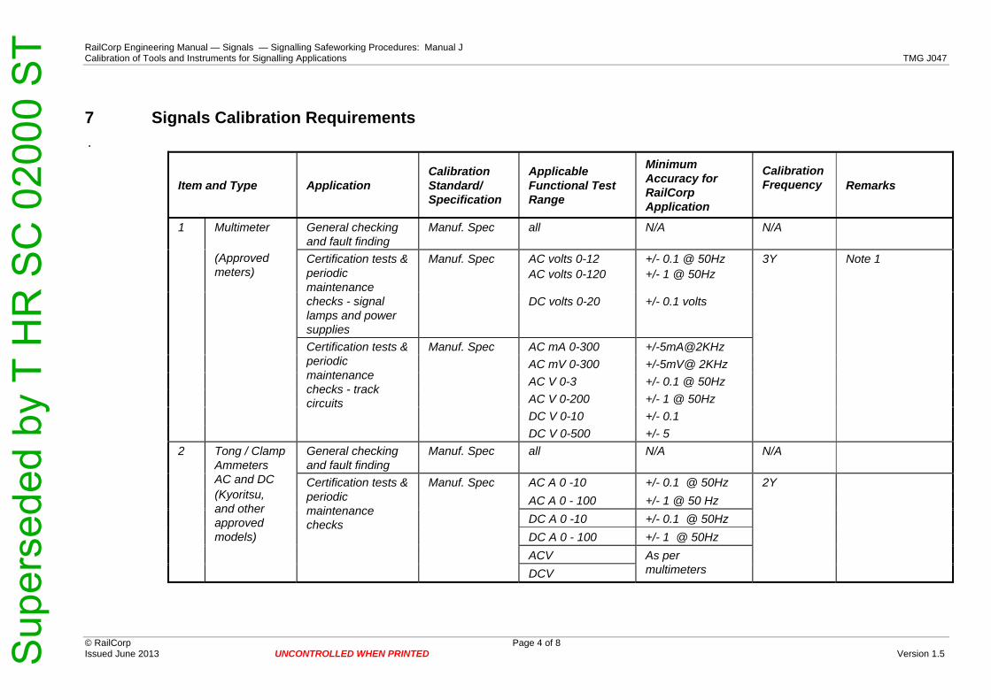
RailCorp Engineering Manual — Signals — Signalling Safeworking Procedures: Manual J Calibration of Tools and Instruments for Signalling Applications TMG J047
7 Signals Calibration Requirements .
Item and Type Application Calibration Standard/ Specification
Applicable Functional Test Range
Minimum Accuracy for RailCorp Application
Calibration Frequency
Remarks
General checking and fault finding
Manuf. Spec all N/A N/A
AC volts 0-12 AC volts 0-120
+/- 0.1 @ 50Hz +/- 1 @ 50Hz
Certification tests & periodic maintenance checks - signal lamps and power supplies
Manuf. Spec
DC volts 0-20 +/- 0.1 volts
AC mA 0-300 +/-5mA@2KHz AC mV 0-300 +/-5mV@ 2KHz AC V 0-3 +/- 0.1 @ 50Hz AC V 0-200 +/- 1 @ 50Hz DC V 0-10 +/- 0.1
1 Multimeter (Approved meters)
Certification tests & periodic maintenance checks - track circuits
Manuf. Spec
DC V 0-500 +/- 5
3Y Note 1
General checking and fault finding
Manuf. Spec all N/A N/A
AC A 0 -10 +/- 0.1 @ 50Hz AC A 0 - 100 +/- 1 @ 50 Hz DC A 0 -10 +/- 0.1 @ 50Hz DC A 0 - 100 +/- 1 @ 50Hz ACV
2 Tong / Clamp Ammeters AC and DC (Kyoritsu, and other approved models)
Certification tests & periodic maintenance checks
Manuf. Spec
DCV As per multimeters
2Y
© RailCorp Page 4 of 8 Issued June 2013 UNCONTROLLED WHEN PRINTED Version 1.5 S
uper
sede
d by
T H
R S
C 0
2000
ST

RailCorp Engineering Manual — Signals — Signalling Safeworking Procedures: Manual J Calibration of Tools and Instruments for Signalling Applications TMG J047
Item and Type Application Calibration Standard/ Specification
Applicable Functional Test Range
Minimum Accuracy for RailCorp Application
Calibration Frequency
Remarks
Meg Ohms */- 5% Output volts 500+10V
3 Insulation resistance tester - ‘Megger’
Measure insulation resistance
Manuf. Spec
Output current into short cct
<3mA
2Y
4 Track circuit Pulse Integrator
General checking and fault finding & certification
RailCorp N/A N/A N/A
General checking and fault finding
RailCorp N/A N/A N/A
ACV 0-2 +/- [email protected] ACV 0-20 +/- 1 @ 2kHz ACV 0-20 +/- 1 @ 2.3kHz ACV 0-20 +/- 1 @ 2.6kHz
5 TFA - Track Circuit Frequency Adaptor
Periodic maintenance checks
RailCorp
ACV 0-20 +/- 1 @ BB
2Y
General checking and fault finding
N/A N/A N/A
ACV 0-2, 20, 200 +/- [email protected] ACV 0-2, 20, 200 +/- 1 @ 2kHz ACV 0-2, 20, 200 +/- 1 @ 2.3kHz ACV 0-2, 20, 200 +/- 1 @ 2.6kHz
6 SFTM - Selective Frequency Track Meter
Periodic maintenance checks
RailCorp
ACV 0-2, 20, 200 +/- 1 @ BB
2Y Tests for all ranges
7 Track Shunt Tester - DN2000
Certification tests & periodic maintenance checks
RailCorp N/A -0 /+5% 4Y See note-2 below
© RailCorp Page 5 of 8 Issued June 2013 UNCONTROLLED WHEN PRINTED Version 1.5 S
uper
sede
d by
T H
R S
C 0
2000
ST

RailCorp Engineering Manual — Signals — Signalling Safeworking Procedures: Manual J Calibration of Tools and Instruments for Signalling Applications TMG J047
Item and Type Application Calibration Standard/ Specification
Applicable Functional Test Range
Minimum Accuracy for RailCorp Application
Calibration Frequency
Remarks
Meg Ohms +/-5% Output volts 500+10V
Measure insulation resistance
Output current into short cct
<3mA
8 Combination Insulation & Continuity Test Set
Continuity
Manuf. Spec
Maximum Ohms 100/+0
4Y
9 Continuity (Bell Test) Set
Continuity Manuf. Spec Maximum Ohms 100/+0 N/A
General checking and fault finding
RailCorp all N/A N/A
AC A 0 -5 +/- 0.2 @ 50Hz 4Y
10 ‘Clancy’ Rail current meter
Periodic and certification testing
RailCorp AC A 0 -55 +/- 0.5 @ 50Hz
(see Note-3 below)
General checking and fault finding
RailCorp N/A N/A N/A
AC A 0 -10 +/- 0.2@ 50Hz 4Y
11 ‘Ras Coil’ rail current transformer Periodic and
certification testing RailCorp
AC A 0 -10 +/- 0.2@ 2Kz
(see Note-3 below)
12 Chart recorder - Analogue
System monitoring Manuf. Spec all manufacturer’s specification
Manuf.Recom.
13 Chart recorder - digital
Event monitoring Manuf. Spec N/A N/A N/A
14 Oscilloscope General testing and fault finding
Manuf. Spec all N/A N/A
© RailCorp Page 6 of 8 Issued June 2013 UNCONTROLLED WHEN PRINTED Version 1.5 S
uper
sede
d by
T H
R S
C 0
2000
ST

RailCorp Engineering Manual — Signals — Signalling Safeworking Procedures: Manual J Calibration of Tools and Instruments for Signalling Applications TMG J047
Item and Type Application Calibration Standard/
Specification
Applicable Functional Test
Range
Minimum Accuracy for
RailCorp Application
Calibration Frequency
Remarks
General testing and fault finding
Manuf. Spec all N/A N/A 15 Oscilloscope / meter combination Measure critical
levels Manuf. Spec all manufacturer’s
specification
Manuf.Recom.
Limiting volts Low scale
+/- 20V 16 Lightning Arrestor Tester
Test arrestors & varistors
RailCorp
High scale +/- 50V
4Y,
see Note-4 below
17 Points gauge Check points adjustment
RailCorp thickness +0 mm 1Y Inspect for damage
18 Trainstop gauge
Check trainstop arm adjustment
RailCorp dimensions +/- 10 mm 1Y Inspect for damage
19 Annett key gauge
Check Annett lock warding
RailCorp N/A N/A N/A
20 Torque wrench
Manuf. Spec torque - Nm Manufacturer’s specification
N/A
21 Cable locator Manuf. Spec Manufacturer’s specification
Manuf.Recom.
22 Measuring wheel
Non-critical distance measurements
Manuf. Spec metres +/- 2% 1Y Inspect for wheel wear
23 Crimping tool Manuf. Spec Tension test on sample crimps
Sigs Std Spec 707
1 wk See Note-5 below
© RailCorp Page 7 of 8 Issued June 2013 UNCONTROLLED WHEN PRINTED Version 1.5 S
uper
sede
d by
T H
R S
C 0
2000
ST
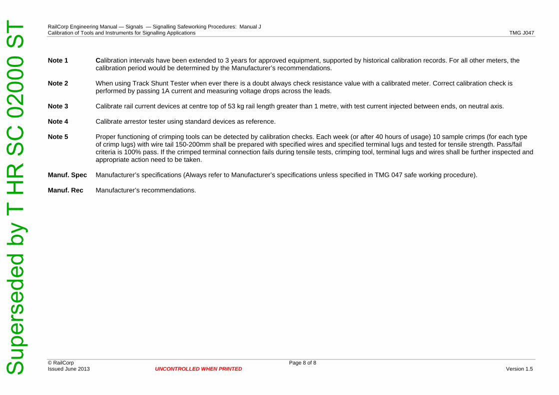
RailCorp Engineering Manual — Signals — Signalling Safeworking Procedures: Manual J Calibration of Tools and Instruments for Signalling Applications TMG J047 Note 1 Calibration intervals have been extended to 3 years for approved equipment, supported by historical calibration records. For all other meters, the
calibration period would be determined by the Manufacturer’s recommendations. Note 2 When using Track Shunt Tester when ever there is a doubt always check resistance value with a calibrated meter. Correct calibration check is
performed by passing 1A current and measuring voltage drops across the leads. Note 3 Calibrate rail current devices at centre top of 53 kg rail length greater than 1 metre, with test current injected between ends, on neutral axis. Note 4 Calibrate arrestor tester using standard devices as reference. Note 5 Proper functioning of crimping tools can be detected by calibration checks. Each week (or after 40 hours of usage) 10 sample crimps (for each type
of crimp lugs) with wire tail 150-200mm shall be prepared with specified wires and specified terminal lugs and tested for tensile strength. Pass/fail criteria is 100% pass. If the crimped terminal connection fails during tensile tests, crimping tool, terminal lugs and wires shall be further inspected and appropriate action need to be taken.
Manuf. Spec Manufacturer’s specifications (Always refer to Manufacturer’s specifications unless specified in TMG 047 safe working procedure). Manuf. Rec Manufacturer’s recommendations.
© RailCorp Page 8 of 8 Issued June 2013 UNCONTROLLED WHEN PRINTED Version 1.5 S
uper
sede
d by
T H
R S
C 0
2000
ST
RailCorp Engineering Manual — Signals — Signalling Safeworking Procedures: Manual J Signalling Locations and Equipment – Security Locks and Keys TMG J048
© RailCorp Page 1 of 12 Issued October 2011 UNCONTROLLED WHEN PRINTED Version 2.0
TMG J048
SIGNALLING LOCATIONS AND EQUIPMENT – SECURITY LOCKS AND
KEYS Version 2.0
Issued October 2011
Document control
Version Date Summary of change 1.0 Replaced SC 00 52 00 48 Signalling Locations and Equipment –
Security Locks and Keys. 1.1 14/01/2008 Changes to reflect the split of signalling infrastructure into separate
ARTC and RailCorp systems and how to deal with locks & keys at the interface between the systems. Also changes to reflect the current usage of keys by licensed RailCorp employees and contractors.
1.2 8/05/2009 Minor amendment to Appendix 2 re design and technical engineers. 1.3 July 2009 Minor amendment to Table 5.1, Section 13, Appendix 1 & 2 1.4 May 2010 Application of TMA 400 format 2.0 October 2011 Updated complete document to reflect current business requirements,
associate the process exclusively for keys issued for signalling infrastructure work, restructure the layout to logically read better.
Contents 1 Introduction .............................................................................................................................3 2 Definitions................................................................................................................................3 3 Old Series Signalling Security Keys .....................................................................................3 4 SL Keys ....................................................................................................................................4 5 Falcon Series Signalling Security Keys................................................................................4
5.1 Series Hierarchy ........................................................................................................4 5.2 Core Configuration Authority .....................................................................................5 5.3 Key Cutting and Numbering ......................................................................................5 5.4 The Locktech Security Keying System......................................................................5
6 Signalling Security Keys - Control Process.........................................................................5 6.1 District Key Controllers ..............................................................................................5 6.2 Supply of Keys...........................................................................................................6 6.3 Key Pool Storage.......................................................................................................6 6.4 Issuance Control........................................................................................................6 6.5 Return of Issued Keys ...............................................................................................6 6.6 Maintenance of Records............................................................................................7
Sup
erse
ded
by T
HR
SC
020
00 S
T

RailCorp Engineering Manual — Signals — Signalling Safeworking Procedures: Manual J Signalling Locations and Equipment – Security Locks and Keys TMG J048
© RailCorp Page 2 of 12 Issued October 2011 UNCONTROLLED WHEN PRINTED Version 2.0
6.7 Key Holder Responsibilities.......................................................................................7 6.7.1 Improper Use..............................................................................................7 6.7.2 Stolen or Lost Keys ....................................................................................7
7 Dual Access Locations...........................................................................................................7 8 Access to Communication Locations...................................................................................8 9 Signal Box Security ................................................................................................................8
9.1 Operational Areas......................................................................................................8 9.2 Underside of Mechanical Signal Boxes .....................................................................8 9.3 Major Signal Boxes....................................................................................................8
10 Emergency Access to Signal Locations...............................................................................8 Appendix A Falcon Key Hierarchy..............................................................................................9 Appendix B Key Types...............................................................................................................10
Sup
erse
ded
by T
HR
SC
020
00 S
T

RailCorp Engineering Manual — Signals — Signalling Safeworking Procedures: Manual J Signalling Locations and Equipment – Security Locks and Keys TMG J048
© RailCorp Page 3 of 12 Issued October 2011 UNCONTROLLED WHEN PRINTED Version 2.0
1 Introduction This procedure describes the issue and use of signalling security keys and locks used to secure signal infrastructure throughout the RailCorp network.
This procedure only governs the issuance of keys used for the purpose of signalling infrastructure work (not for operational purposes).
2 Definitions Central Key Controller: The position of Technical Specialist Mechanical Signalling within the Chief Engineers Division, delegated to approve District Key Controllers and control the bulk issue of keys issued to the District Key Controller.
District Key Controller: The positions in RailCorp responsible for the control of the District Key Pool, for the issue of keys to a Key Holder and to maintain such records.
Central Key Pool: The stock of keys held by the Central Key Controller to service requests for stock from District Key Controllers.
District Key Pool: The stock of keys held by the District Key Controller.
Key Holder: The person authorised to be in possession of any signalling security key.
Keys Types: As listed in Appendix B
3 Old Series Signalling Security Keys Typically, these keys are not in general use and will therefore only be issued on a needs basis to signalling personnel as defined in Table 1.
Position Key
Licensed Signal
Engineer
Signal Electrician
Licensed Signals
Mechanical
Licensed Signals Ancillary
Signals Authorised
Person Best 7 Yes No No No No Best 8 N/A Yes Yes Yes Yes Yale 6 Yes Yes No No Yes Yale 9 Yes Yes Yes Yes Yes Yale R Yes Yes No No No SWI old Yes Yes No No No SWI new Yes Yes No No No Staff old Yes Yes No No No Staff new Yes Yes No No No STEL Yes Yes Yes Yes Yes
PIM Yes Yes Interlocking Fitter only No No
Corbin old Yes Yes No No No Corbin new Yes Yes No No No
Table 1 - Old Series Signalling and Safeworking Keys
Sup
erse
ded
by T
HR
SC
020
00 S
T
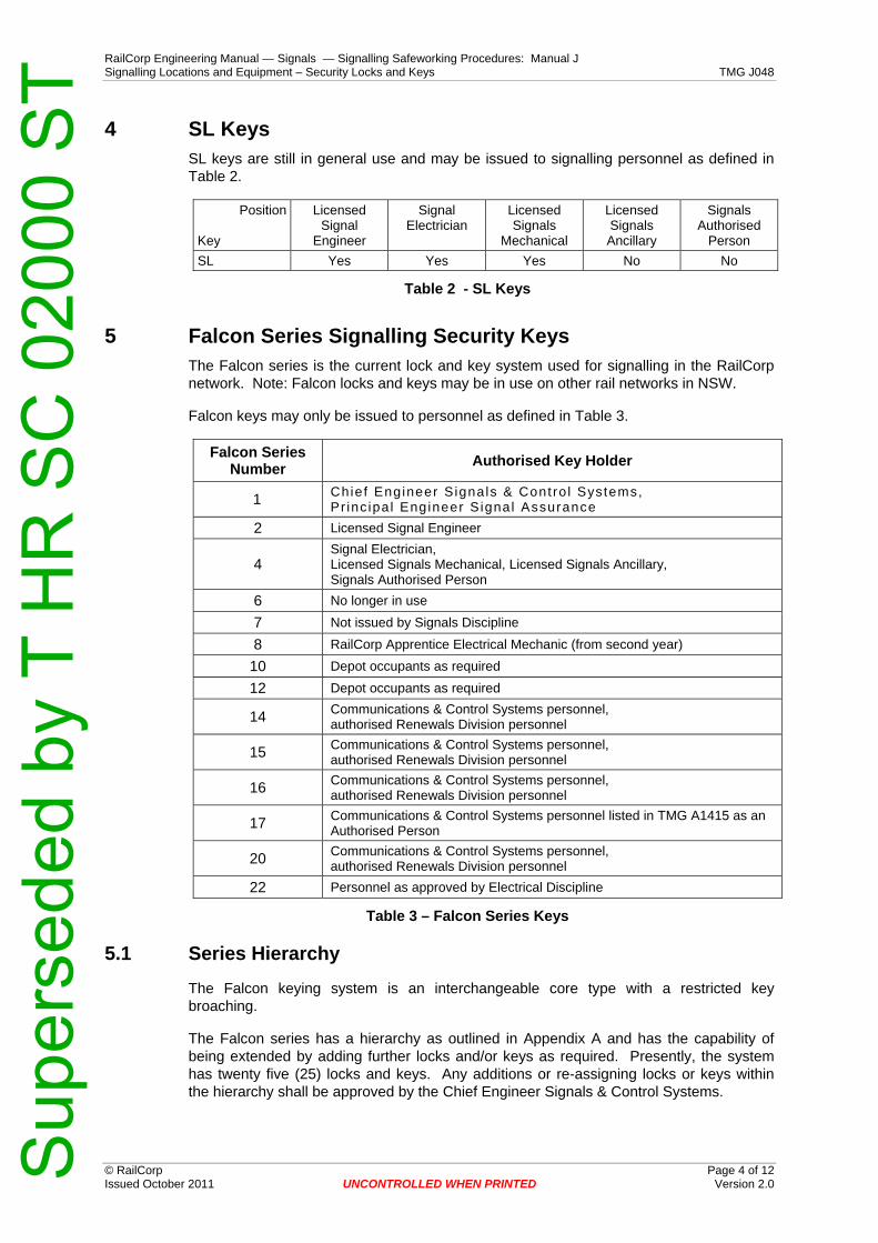
RailCorp Engineering Manual — Signals — Signalling Safeworking Procedures: Manual J Signalling Locations and Equipment – Security Locks and Keys TMG J048
© RailCorp Page 4 of 12 Issued October 2011 UNCONTROLLED WHEN PRINTED Version 2.0
4 SL Keys SL keys are still in general use and may be issued to signalling personnel as defined in Table 2.
Position Key
Licensed Signal
Engineer
Signal Electrician
Licensed Signals
Mechanical
Licensed Signals Ancillary
Signals Authorised
Person SL Yes Yes Yes No No
Table 2 - SL Keys
5 Falcon Series Signalling Security Keys The Falcon series is the current lock and key system used for signalling in the RailCorp network. Note: Falcon locks and keys may be in use on other rail networks in NSW.
Falcon keys may only be issued to personnel as defined in Table 3.
Falcon Series Number Authorised Key Holder
1 Chief Engineer S ignals & Contro l Systems, Pr inc ipa l Engineer S ignal Assurance
2 Licensed Signal Engineer
4 Signal Electrician, Licensed Signals Mechanical, Licensed Signals Ancillary, Signals Authorised Person
6 No longer in use
7 Not issued by Signals Discipline
8 RailCorp Apprentice Electrical Mechanic (from second year)
10 Depot occupants as required
12 Depot occupants as required
14 Communications & Control Systems personnel, authorised Renewals Division personnel
15 Communications & Control Systems personnel, authorised Renewals Division personnel
16 Communications & Control Systems personnel, authorised Renewals Division personnel
17 Communications & Control Systems personnel listed in TMG A1415 as an Authorised Person
20 Communications & Control Systems personnel, authorised Renewals Division personnel
22 Personnel as approved by Electrical Discipline
Table 3 – Falcon Series Keys
5.1 Series Hierarchy
The Falcon keying system is an interchangeable core type with a restricted key broaching.
The Falcon series has a hierarchy as outlined in Appendix A and has the capability of being extended by adding further locks and/or keys as required. Presently, the system has twenty five (25) locks and keys. Any additions or re-assigning locks or keys within the hierarchy shall be approved by the Chief Engineer Signals & Control Systems.
Sup
erse
ded
by T
HR
SC
020
00 S
T

RailCorp Engineering Manual — Signals — Signalling Safeworking Procedures: Manual J Signalling Locations and Equipment – Security Locks and Keys TMG J048
© RailCorp Page 5 of 12 Issued October 2011 UNCONTROLLED WHEN PRINTED Version 2.0
5.2 Core Configuration Authority
The configuration of Falcon interchangeable cores shall be performed by the RailCorp Locksmith. Where this is not achievable, then the configuration shall be performed by a qualified external locksmith who is member of the Master Locksmiths Association, with close supervision from a licensed Signal Engineer to ensure the security of the pinning charts is maintained.
5.3 Key Cutting and Numbering
The RailCorp Locksmith shall hold all key blanks and arrange for the cutting and numbering of all keys, ensuring that the allocation of numbers is unique.
Each key shall be stamped with the key number, a unique allocation number and "RAILCORP DO NOT COPY".
5.4 The Locktech Security Keying System
An approved alternate supply of cylinder cores and keys has been arranged through Locktech Industries. There is a slight difference in the key profile between the Falcon and Locktech keys. The Locktech cores can be pinned the same as the Falcon system and can be opened by either a Falcon or a Locktech key. The Locktech keys cannot be used to open locks fitted with Falcon cores.
6 Signalling Security Keys - Control Process 6.1 District Key Controllers
The listing of Key Controllers is defined in Table 4. The delegation of officers shall be approved by the Chief Engineer Signals & Control Systems and managed by the Central Key Controller.
Series Number Business Group District Key Controller
1, 2, 4 and SL Chief Engineers Division – Signals & Control Systems
Technical Specialist Mechanical Signalling
2, 4, 6, 8, 9, 10, 11, 12 18 and SL Infrastructure Maintenance Division Maintenance Signal Engineers,
IOC Manager
Renewals Division Delegated Renewals Division Signalling Officer
Projects Division Delegated Projects Division Signalling Officer 4, 6, 8, 10, 13 and
SL
External Signalling Resources
Relevant Division Key Controller issuing the Permit to Work certificate or Technical Specialist Mechanical Signalling
7 Network Operations Not controlled by Signals Discipline
14, 15, 16 17 and 21
Communications & Control Systems – Communications Delegated officer in C&CS Division
4 Communications & Control Systems – Control Systems
Technical Specialist Mechanical Signalling
22 Electrical Maintenance Engineer Engineering Operations Manager
Delegated officer in Electrical Discipline
Table 4 - Approved District Key Controllers
Sup
erse
ded
by T
HR
SC
020
00 S
T

RailCorp Engineering Manual — Signals — Signalling Safeworking Procedures: Manual J Signalling Locations and Equipment – Security Locks and Keys TMG J048
© RailCorp Page 6 of 12 Issued October 2011 UNCONTROLLED WHEN PRINTED Version 2.0
6.2 Supply of Keys
The Central Key Controller shall maintain a Key Pool to meet expected demand.
The RailCorp Locksmith shall supply keys for the Central Key Pool upon request from the Central Key Controller.
The District Key Controller shall maintain a Key Pool to meet the expected demand.
The Central Key Controller shall supply keys for the District Key Pool upon request from District Key Controllers.
The RailCorp Locksmith shall maintain comprehensive records of:
• All requests for the supply of keys and locks. • Key blanks in stock. • Keys issued to or returned by the Central Key Controller.
6.3 Key Pool Storage
District Key Pools are to be stored in a safe, or in a secure cabinet. Access to the key pool should be restricted to the District Key Controller and no more than one other person nominated by them. Storing the keys on a rack of hooks, or in a multi-compartment case within the safe or cabinet should simplify the process of finding the relevant keys. If the District Key Controller is not the custodian of the key for the safe then a lockable cashbox or something similar is to be used to store the keys within the safe.
The RailCorp Locksmith shall secure all blanks and cut keys in a safe or secure cabinet.
6.4 Issuance Control
Signalling personnel listed in TMG A1415 who hold a current RailCorp Permit to Work may make application to the District Key Controller for the issue of appropriate security keys required for the work in accordance with this procedure.
Senior Signal Engineers in RailCorp as listed in TMG A1415 may hold appropriate signalling security keys in accordance with Table 3 without requiring a Permit to Work certificate.
The issue of security keys shall be recorded with details of the individual concerned (position, location, contact details, employer, etc.) and date of issue.
Issued keys may be retained by the Key Holder subject to the provisions prescribed in 6.5.
6.5 Return of Issued Keys
Key Holders shall return their signalling security keys to their respective Key Controller when there is no longer justification for the person to have those keys, or where a person ceases carrying out work for RailCorp, or where a RailCorp Permit to Work expires or is revoked.
RailCorp employees exiting from the organisation shall also return their signalling keys to the District Key Controller. A new issue of keys shall be provided in accordance within the provisions stated in 6.4.
Sup
erse
ded
by T
HR
SC
020
00 S
T

RailCorp Engineering Manual — Signals — Signalling Safeworking Procedures: Manual J Signalling Locations and Equipment – Security Locks and Keys TMG J048
© RailCorp Page 7 of 12 Issued October 2011 UNCONTROLLED WHEN PRINTED Version 2.0
6.6 Maintenance of Records
Databases shall be used to record and control the supply, issue, transfer, maintenance and return of signalling security keys.
The maintenance of records shall be the responsibility of the Central Key Controller and the District Key Controllers nominated in 6.1.
When signalling personnel transfer to another RailCorp position or depot location, and they are authorised to retain their signalling keys, then their key record shall be transferred with them.
6.7 Key Holder Responsibilities
The responsibility for the proper use and care of keys lies with the individual key holder. Keys are not to be lent, copied or defaced and any damaged or broken keys shall be immediately returned to the appropriate Key Controller for replacement.
6.7.1 Improper Use
Improper use of signalling security keys will result in the keys being confiscated. Improper use would include:
• Use of a key without appropriate authorisation • Use of a key to unlock infrastructure and fail to make it secure before leaving the
site • Failing to adequately secure keys against theft or loss • Allowing issued keys to be used by unauthorised persons • Use of a key when not engaged to undertake work for RailCorp
6.7.2 Stolen or Lost Keys
Key Holders shall report all keys that are lost or stolen. The report shall be in the form of a Statutory Declaration detailing the circumstances of the loss. This report shall be sent to the issuing Key Controller and a copy forwarded to the Key Holder's controlling officer.
7 Dual Access Locations Dual access to signalling, communication and electrical equipment locations shall be provided on a needs basis to persons where the work required to be done, is performed within their respective area of authority.
Dual access to communication locations shall be provided by installation of a Falcon No.17 lock. The provision of these locks shall be jointly approved the Chief Engineer Signals & Control Systems and the Chief Engineer Telecommunications. Issue of Falcon No.17 keys to Communications & Control Systems personnel shall be approved by the GM Communications & Control Systems. Signalling personnel may gain access to these locations using a Falcon No.4 key.
Dual access to electrical locations shall be provided by installation of a Falcon No.22 lock. The provision of these locks shall be jointly approved the Chief Engineer Signals & Control Systems and the Chief Engineer Electrical. Issue of Falcon No.22 keys to Electrical Discipline personnel shall be approved by the Electrical Maintenance Engineer Engineering Operations Manager. Signalling personnel may gain access to these locations using a Falcon No.4 key.
Sup
erse
ded
by T
HR
SC
020
00 S
T
RailCorp Engineering Manual — Signals — Signalling Safeworking Procedures: Manual J Signalling Locations and Equipment – Security Locks and Keys TMG J048
© RailCorp Page 8 of 12 Issued October 2011 2.0 UNCONTROLLED WHEN PRINTED Version
Note: Non-signalling personnel shall only enter a signalling location if authorised by the Maintenance Signal Engineer or Commissioning Engineer in accordance with TMG A1412.
Keys shall be issued by the respective District Key Controller.
8 Access to Communication Locations The District Key Controller in Renewals Division shall nominate personnel to the GM Communications & Control Systems for authorisation to gain access to communications facilities for the purpose of cable locating, cable jointing and other similar roles.
The GM Communications & Control Systems shall authorise the District Key Controller in Renewals Division to issue the required Falcon keys as deemed necessary for the work.
9 Signal Box Security 9.1 Operational Areas
Falcon No.7 locks are no longer fitted to the operational areas of existing Signal Boxes. The locks to these areas are the responsibility of operational managers.
9.2 Underside of Mechanical Signal Boxes
Falcon No.7 locks are no longer fitted to the underside of mechanical Signal Boxes. This access shall now be secured with a Falcon No.4 lock.
9.3 Major Signal Boxes
Major Signal Boxes (Control Centres) are fitted with propriety card type security access systems. The maintenance of these systems is the responsibility of operational managers. The Maintenance Signal Engineer, or his delegated representative, shall ensure only authorised signalling personnel have access to signalling rooms within these buildings.
Signalling equipment rooms within Major Signal Boxes are to be secured with appropriate Falcon series locks.
10 Emergency Access to Signal Locations An emergency Falcon No.4 key shall be kept at the Infrastructure Operations Centre (IOC) for emergency access to signal locations.
Sup
erse
ded
by T
HR
SC
020
00 S
T

ering Manual — Signals — Signalling Safeworking Procedures: Manual J ons and Equipment – Security Locks and Keys TMG J048
© RailCorp Page 9 of 12 Issued October 2011 Version 2.0
3 4 5 6 7 8 11 12 13 17 224 RELAY ROOM 4 ELECT 4 6 7 8 9 10 11 12 17 22
4X RELAY ROOM 4 45 PROJECT SECURITY 2 5 4 5 6 7 8 11 12 13 17 226 U/S SIGNAL BOXES 6 6 7 8 9 10 11 127 OPERATIONS (SIG BOXES) 7 E S 78 SIGNALLING EQUIPMENT 8 PADLOCK (STEL replacement) 89 DISTRICT STORES 9 910 ELECTRICIANS/SECTMANS DEPOT 10 10 11 1211 AMENITIES (RESTRICTED) 1 1112 AMENITIES (GENERAL) 12 ERAL) 1213 PROJECT STORES 13 1314 COMMS-CITYRAIL 14 L 14 15 16 18 2115 COMMS-CITYRAIL 15 COMMS-CITYRAIL 15 18 20A 2116 COMMS-SPARE 16 COMMS-SPARE 1617 COMMS-JOINT ACCESS 17 COMMS-JOINT ACCESS 1718 COMMS-CITYRAIL 18 COMMS-CITYRAIL NOT FOR ISSUE 18 20A 2119 SPARE 19 SPARE20 SPARE ON LOAN 20 SPARE ON LOAN TRAIN RADIO 20 20A
20A COMMS-TRAIN RADIO 20A TRAIN RADIO 20A21 COMMS-CITYRAIL 21 COMMS-CITYRAIL FOR USE BY TELSTRA 2122 ELECTRICAL (R SERIES) 22 ELECTRICAL (R) (OPTION 22,23,24) 2223 ELECTRICAL 23 ELECTRICAL 2324 ELECTRICAL 24 ELECTRICAL 2425 ELECTRICAL SPARE 25 ELECTRICAL SPARE 2526 26 EMERGENCY KEY 4 6
UNCONTROLLED WHEN PRINTED
NOT REQUIREDSUB-MAST MAINNOT REQUIREDNOT REQUIREDNOT REQUIREDOP RATION
NOT REQUIREDDEPOT
1 NOT REQUIREDAMENITIES (GENNOT REQUIREDCOMMS-CITYRAI
LOCK No. KEY OPENS LOCKS1 1 MASTER 1 2 3 4 5 6 7 8 9 10 11 12 13 14 15 16 17 18 19 20 20A 21 22 23 24 252 DISTRICT SECURITY 2 SUB-MASTER D.E. 2 4 6 7 8 9 10 11 12 17 223 PROJECT SECURITY 1 3
Appendix A Falcon Key Hierarchy
RailCorp EngineSignalling Locati
Sup
erse
ded
by T
HR
SC
020
00 S
T

RailCorp Engineering Manual — Signals — Signalling Safeworking Procedures: Manual J Signalling Locations and Equipment – Security Locks and Keys TMG J048
Appendix B Key Types
In General Use
Falcon Series Numbered
SL Not Numbered
Not in General Use
Best Series Numbered
Yale 6 Numbered
Yale 9 Numbered
Yale R Numbered
© RailCorp Page 10 of 12 Issued October 2011 UNCONTROLLED WHEN PRINTED Version 2.0 Sup
erse
ded
by T
HR
SC
020
00 S
T

RailCorp Engineering Manual — Signals — Signalling Safeworking Procedures: Manual J Signalling Locations and Equipment – Security Locks and Keys TMG J048
Not in General Use (cont'd)
STEL Not Numbered (all numbered 1020)
Corbin New Not Numbered
Corbin Old Not Numbered
SWI New - ABLOY Numbered
SWI Old Numbered
Staff New Numbered
Staff Old Numbered
PIM Numbered
© RailCorp Page 11 of 12 Issued October 2011 UNCONTROLLED WHEN PRINTED Version 2.0 Sup
erse
ded
by T
HR
SC
020
00 S
T

RailCorp Engineering Manual — Signals — Signalling Safeworking Procedures: Manual J Signalling Locations and Equipment – Security Locks and Keys TMG J048
© RailCorp Page 12 of 12 Issued October 2011 UNCONTROLLED WHEN PRINTED Version 2.0
This page has been intentionally left blank
Sup
erse
ded
by T
HR
SC
020
00 S
T

RailCorp Engineering Manual — Signals — Signalling Safeworking Procedures: Manual J Signal Engineering Waivers TMG J049
© RailCorp Page 1 of 8 Issued May 2010 UNCONTROLLED WHEN PRINTED Version 2.0
TMG J049 SIGNAL ENGINEERING WAIVERS
Version 2.0
Issued May 2010
Document control
Version Date Summary of change 1.0 Replaced SC 00 52 00 49 SI Signal Engineering Waivers. 1.1 10 October 2007 Update Sections 3.2, 3.3 & 4.1 1.2 03 November 2008 Update 2.1 Requesting Officer definitions
2.0 May 2010
Rewrite of complete document to clearly describe process. Amend Signal Engineering Waiver Request for Approval form. Signal Concession separated from this document. Application of TMA 400 format
Contents 1 Introduction .............................................................................................................................2
1.1 Scope.........................................................................................................................2 1.2 Purpose .....................................................................................................................2
2 Approval Process for Signalling Design ..............................................................................2 3 Definitions................................................................................................................................3 4 Waiver Categories...................................................................................................................3 5 Waiver Evaluation and Submission ......................................................................................4 6 Waiver Review .........................................................................................................................4 7 Waiver Approval......................................................................................................................5 8 Waiver Registration and Distribution....................................................................................5 9 Waiver Rejection .....................................................................................................................5 10 Expired Waivers ......................................................................................................................5 11 Waiver Periodic Review..........................................................................................................5 Appendix A Signal Engineering Waiver Approval Form...........................................................6
Sup
erse
ded
by T
HR
SC
020
00 S
T

RailCorp Engineering Manual — Signals — Signalling Safeworking Procedures: Manual J Signal Engineering Waivers TMG J049
© RailCorp Page 2 of 8 Issued May 2010 UNCONTROLLED WHEN PRINTED Version 2.0
1 Introduction Engineering Authority for the Signalling Discipline is held by the RailCorp Chief Engineer Signals & Control Systems. Signal Engineering Standards, Signalling Safeworking Procedures and Signalling Equipment Specifications provide the processes required to design, supply, install and maintain signalling infrastructure, ensuring a safe and reliable system.
Unless a Signal Engineering Waiver (here on known as a waiver) or Concession is granted, or an approved design is issued, variation from the specified standard or procedure shall not be permitted.
1.1 Scope This document sets out the RailCorp Signalling Discipline requirement for the submission, evaluation and approval of temporary variations from Signal Engineering Standards, Signalling Safeworking Procedures and Signalling Equipment.
Variation of permanent situations, such as requests for one-off approvals of distinctive equipment, eg: treatment of a manufacturer's one-off supply of a multicore cable missing inscription on one core, shall be submitted as a Signal Engineering Concession. The Signal Engineering Concession process is described separately in TMG J050.
1.2 Purpose The purpose of this document is to specify the requirement to:
a) Determine and evaluate the initial need to vary from current RailCorp Signal Engineering Standards, Signalling Safeworking Procedures and Signalling Equipment Specifications.
b) Assess all the risks associated with the variation, apply mitigating risk controls/conditions and identify persons responsible for actioning risk controls.
c) Appraise waiver requests at the recommendation stage.
d) Approve or decline waiver requests.
This will ensure that all the safety and technical risks associated with the variation are satisfactorily identified, mitigated and managed throughout the valid period of the waiver prior to granting approval for the waiver.
2 Approval Process for Signalling Design Approval for the issue of new or altered signalling design, including vital data, electrical and mechanical designs, are to be in accordance with the design approval process described in the Signal Engineering Standards, particularly SPG 0711 and SPG 0703.
Where specific variation is required for a particular situation, eg: a variation from standard design for the installation of a signal base, then this can be arranged as a design approval by due consideration and endorsement from the relevant signal project engineer and subsequent approval from the Chief Engineer Signals & Control Systems or delegated subject matter expert.
The process for temporary cable routes is described in specification SPG 0705.
Sup
erse
ded
by T
HR
SC
020
00 S
T

RailCorp Engineering Manual — Signals — Signalling Safeworking Procedures: Manual J Signal Engineering Waivers TMG J049
© RailCorp Page 3 of 8 Issued May 2010 UNCONTROLLED WHEN PRINTED Version 2.0
3 Definitions The following defined terms are used throughout this procedure:
Signal Engineering Waiver (waiver) An approved temporary variation from Signal Engineering Standards, Signalling Safeworking Procedures or Signalling Equipment Specifications.
Signal Engineering Standards Refers to the suite of RailCorp Signal Engineering Standards and Specifications, including Inspection & Testing Procedures, Competency and Licensing Standards that are required for the installation, inspection, testing and commissioning of new or altered signalling infrastructure.
Signalling Safeworking Procedures Refers to the suite of RailCorp Signalling Safeworking Procedures, including Competency and Licensing Standards and any other applicable signalling procedure or instruction that is required for proper maintenance and asset management of the signalling system.
Signalling Equipment Specifications Refers to type approval of equipment or system, including supporting systems and products, which form part of signalling infrastructure. Also includes measuring and locating equipment or speciality tools used on signalling infrastructure.
Requesting Officer A person who identifies and proposes a temporary variation of an item or matter that does not, or will not comply with RailCorp’s Signal Engineering Standards, Signalling Safeworking Procedures or Signalling Equipment Specifications.
The Requesting Officer shall be a licensed Signal Engineer or a person with the appropriate signal engineering authority.
Risk Control Officer A suitable person identified as having responsibility for actioning risk mitigation control(s) as addressed in the waiver submission.
Sponsor Typically a licensed RailCorp Signal Engineer at managerial level with relevant authority who shall provide comment and endorsement on the signal engineering waiver submission.
Reviewing Officer A subject matter expert with delegated authority from RailCorp Chief Engineers Division, Signals & Control Systems, who is responsible for evaluating the waiver request prior to submission for approval.
Approving Officer The Chief Engineer Signals & Control Systems.
4 Waiver Categories Waivers are defined into five fundamental elements that permit acceptance of a non compliant signalling item or matter. Waiver categories are as follows:
a) Signalling safeworking & maintenance (TMG Manual J).
b) Inspection, testing & commissioning of new or altered signalling (SPG 0711).
c) Signalling installation – temporary situations not provided by another process (Construction Specifications).
d) Signalling products, equipment & technical matters – temporary use of these items (Equipment Specifications).
e) Competency of signalling personnel to work on RailCorp signalling infrastructure (TMG A1415/1417 & TMG J001/010).
Sup
erse
ded
by T
HR
SC
020
00 S
T
RailCorp Engineering Manual — Signals — Signalling Safeworking Procedures: Manual J Signal Engineering Waivers TMG J049
© RailCorp Page 4 of 8 Issued May 2010 UNCONTROLLED WHEN PRINTED Version 2.0
5 Waiver Evaluation and Submission The Requesting Officer shall submit a Signal Engineering Waiver - Request for Approval form, requesting a waiver in response to an identified temporary variation to a non compliant signalling item or matter.
The submission shall include an evaluation of the waiver request and a safety and technical risk assessment of the waived variation which shall be submitted with the Signal Engineering Waiver - Request for Approval form. The risk assessment shall identify all risks associated with the variation and specify the controls necessary to manage such risks. A Risk Control Officer shall be identified to action each of the risk controls.
Where the Requesting Officer is not a suitably licensed Signal Engineer or the waiver is complex, or involves a high level of risk, then a Sponsor shall be arranged to provide comment on the waiver request. The provision of a Sponsor may also be requested by the Principal Engineer Signal Operations & Assurance. The Sponsor, if satisfied that all the requirements have been met, shall endorse the waiver request. Typically, the Sponsor shall be a licensed RailCorp Signal Engineer at managerial level with relevant authority.
Affected stakeholders shall be notified of the pending waiver and additionally provide comment on the submission.
The Signal Engineering Waiver - Request for Approval form, including all supporting documentation, shall be forwarded to the Principal Engineer Signal Operations and Assurance.
6 Waiver Review Waiver submissions shall be registered upon receipt by the Principal Engineer Signal Operations & Assurance prior to review.
The Reviewing Officer shall ensure the reason for waiver, detail of variation, identification of risks, specification of controls and conditions (including operating circumstances) are clearly compiled on the Signal Engineering Waiver – Request for Approval form, including all supporting material, photos, calculations, drawings and any other correspondence necessary to demonstrate adequate management of all identified risks.
The Reviewing Officer shall evaluate the need for the waiver, review the safety and technical risk assessment and ensure all associated risks are mitigated by suitable controls and conditions necessary to manage the risks and that a Risk Control Officer has been allocated to action each of the risk controls.
Risks associated with any temporary variation of a non compliant signalling item or matter may be judged to be acceptable, either by implementing suitable controls to manage the risk or by assessing local operating conditions of that signalling infrastructure to be less rigorous than those assumed by the formal standard, procedure or specification.
The Reviewing Officer shall ensure all affected stakeholders have been identified, notified and had the opportunity to provide comment. Their comments shall be taken into account during the review phase. The Reviewing Officer may liaise with the Requesting Officer, Sponsor or affected stakeholders to establish a clear understanding of the key elements of the waiver request.
The Reviewing Officer shall provide comment where necessary and either recommend (if satisfied that all the requirements have been met) or not-recommend the waiver request, then forward the submission to the Chief Engineer Signals & Control Systems for determination.
Sup
erse
ded
by T
HR
SC
020
00 S
T

RailCorp Engineering Manual — Signals — Signalling Safeworking Procedures: Manual J Signal Engineering Waivers TMG J049
© RailCorp Page 5 of 8 Issued May 2010 UNCONTROLLED WHEN PRINTED Version 2.0
7 Waiver Approval The Approving Officer shall examine the presented evidence including any recommendations or concerns raised by the Reviewing Officer and judge that all significant risks have been identified and adequately addressed in the proposed conditions of the waiver.
Once satisfied, the Approving Officer can approve the waiver.
Once approved, the Signal Engineering Waiver – Request for Approval form shall be returned to the Principal Engineer Signal Operations & Assurance along with all supporting documentation.
8 Waiver Registration and Distribution Once a waiver request is approved, the Principal Engineer Signal Operations & Assurance shall:
a) Update the waiver database.
b) Advise and return a copy of the approved Signal Engineering Waiver Request for Approval form to the Requesting Officer, Sponsor (as applicable) and affected stakeholders.
9 Waiver Rejection Waivers not approved by the Approving Officer shall have comments explaining the reasons for rejection and then returned to the Principal Engineer Signal Operations & Assurance for final processing
The Principal Engineer Signal Operations & Assurance shall either contact or arrange the Reviewing Officer (subject matter expert) to contact and advise the Requesting Officer of the details for the waiver rejection and where appropriate, recommend alternate arrangements.
The Requesting Officer may re-submit the waiver request where they are able to demonstrate, to the satisfaction of the Reviewing Officer, that an alternate approach or provision of additional risk controls would address the reasons / concerns stated in the original waiver’s rejection.
10 Expired Waivers Requesting Officers shall be responsible for ensuring waived provisions do not exceed the expiry date.
Request for any extension to a waiver period shall be made in a timely manner prior to the expiry date with due consideration of the impacts or additional risks imposed by the extension.
Where current waivers are no longer required, notification shall be made to the Principal Engineer Signal Operations & Assurance to have the waiver withdrawn.
11 Waiver Periodic Review The Principal Engineer Signal Operations & Assurance shall conduct an annual review of all issued waivers to determine status and risk. The review shall assess the requirement to update any standards relating to a particular waiver. All waivers which are determined to be no longer required shall be withdrawn.
Sup
erse
ded
by T
HR
SC
020
00 S
T

RailCorp Engineering Manual — Signals — Signalling Safeworking Procedures: Manual J Signal Engineering Waivers TMG J049
Appendix A Signal Engineering Waiver Request for Approval
Signalling Safeworking & Maintenance.
Inspection, Testing & Commissioning of new or altered Signalling.
Signalling Installation Practices – temporary situations.
Signalling Products, Equipment & Technical matters – temporary use.
Competency Signalling Personnel to work on RailCorp Signalling Infrastructure.
Waiver Category
Waiver Number: (Allocated by Principal Engineer Signal Operations & Assurance)
START DATE:
EXPIRY DATE:
REQUESTED BY:
RELEVANT STANDARD / PROCEDURE:
DISTRICT OR PROJECT:
LOCATION:
EQUIPMENT AFFECTED: (As applicable)
VARIATION DESCRIPTION:
VARIATION DETAILS:
© RailCorp Page 6 of 8 Issued May 2010 UNCONTROLLED WHEN PRINTED Version 2.0 Sup
erse
ded
by T
HR
SC
020
00 S
T

RailCorp Engineering Manual — Signals — Signalling Safeworking Procedures: Manual J Signal Engineering Waivers TMG J049
© RailCorp Page 7 of 8 Issued May 2010 UNCONTROLLED WHEN PRINTED Version 2.0
Waiver Number:
RISKS/ CONTROLS / CONDITIONS: (A Risk Control Officer, responsible for actioning each risk control / condition, is to be clearly identified)
ATTACHMENTS: (As applicable)
REQUESTING OFFICER
Signature: Date:
Name:
Position:
STAKEHOLDER: (As applicable)
Name / Comment:
Sup
erse
ded
by T
HR
SC
020
00 S
T

RailCorp Engineering Manual — Signals — Signalling Safeworking Procedures: Manual J Signal Engineering Waivers TMG J049
© RailCorp Page 8 of 8 Issued May 2010 UNCONTROLLED WHEN PRINTED Version 2.0
Waiver Number:
SPONSOR’S ENDORSEMENT: (As applicable)
Comment:
Signature: Date:
Name:
Position:
REVIEWING OFFICER
Recommended Not Recommended (Cross out not applicable)
Comment:
Signature: Date:
Name:
Position:
APPROVING OFFICER:
Decision: Approved Not Approved (Cross out not applicable)
Comments:
Signature: Date:
Name:
Position: Chief Engineer Signals & Control Systems
Sup
erse
ded
by T
HR
SC
020
00 S
T