tmg e1420 engineering manual - transport for nsw · railcorp engineering manual — signals —...
TRANSCRIPT

Engineering Manual Signals Maintenance Manual
TMG E1420
MECHANICAL POINTS ANDGROUND FRAMES
Version 2.1
Issued May 2010
Owner: Warwick Allison, Chief Engineer Signals and Control Systems
Approved Warwick Allison Authorised Paul Szacsvay by: Chief Engineer by: Principal Engineer
Signals and Control Systems Signal Technology
Disclaimer
This document was prepared for use on the RailCorp Network only.
RailCorp makes no warranties, express or implied, that compliance with the contents of this document shall be sufficient to ensure safe systems or work or operation. It is the document user’s sole responsibility to ensure that the copy of the document it is viewing is the current version of the document as in use by RailCorp.
RailCorp accepts no liability whatsoever in relation to the use of this document by any party, and RailCorp excludes any liability which arises in any manner by the use of this document.
Copyright
The information in this document is protected by Copyright and no part of this document may be reproduced, altered, stored or transmitted by any person without the prior consent of RailCorp.
En
gin
eeri
ng
Man
ual

RailCorp Engineering Manual — Signals — Maintenance Manual Mechanical Points and Ground Frames TMG E1420
Document control
Version Date Summary of change
Replaced SC 07 34 01 11 EQ – Mechanical Points and Ground Frames – v1.1 of 23 January 2006.
1.0 21/08/2007 New RailCorp format.
2.0 24/03/2010 New RailCorp format. Added Westinghouse HDLM point lock and detector. Edited reference to facing point lock.
2.1 May 2010 Application of TMA 400 format.
© RailCorp Page 2 of 46 Issued May 2010 UNCONTROLLED WHEN PRINTED Version 2.1

RailCorp Engineering Manual — Signals — Maintenance Manual Mechanical Points and Ground Frames TMG E1420
Contents
1 Introduction .............................................................................................................................5
1.1 Scope.........................................................................................................................5
1.2 Referenced Publications............................................................................................5
1.3 Definitions ..................................................................................................................5
2 Equipment Description...........................................................................................................7
2.1 Physical Description ..................................................................................................7
2.1.1 Mechanical Ground Frames.......................................................................7
2.1.2 Channel Rodding Drive ..............................................................................7
2.1.3 Mechanical Points ....................................................................................11
2.2 Principles of Operation ............................................................................................14
2.2.1 Compensation ..........................................................................................14
2.2.1.1 Types of Compensator..............................................................15
2.2.1.2 Unequal Arm Cranks.................................................................16
2.2.1.3 Shaded Sections of Channel Rodding......................................16
2.2.1.4 Compensation for Ground Frames ...........................................16
2.2.2 Two and Three Lever Ground Frame Locking .........................................17
2.3 Facing Point Lock ....................................................................................................21
2.4 Westinghouse HDLM Point Lock with Detector.......................................................21
3 Operational and Functional Checks....................................................................................22
3.1 Check Intervals ........................................................................................................22
3.2 Ground Frames........................................................................................................22
3.2.1 Ground Frames - Interlocking Test ..........................................................22
3.2.1.1 Ground Frames fitted with Electric Locks .................................22
3.2.1.2 Ground Frames fitted with Annett Locks orOperators Locks........................................................................23
3.2.1.3 Two Lever Frames – Typical “In One Way” FacingPoint or Trailing Point Application.............................................23
3.2.1.4 Three Lever Frames – Typical “In Both Ways”Facing Point Application ...........................................................23
3.2.1.5 Two and Three Lever Frames – Other Applications.................24
3.3 Channel Rodding Drive............................................................................................24
3.4 Points .......................................................................................................................27
3.4.1 Trailing points ...........................................................................................27
3.4.2 Facing Points............................................................................................27
4 On System Maintenance.......................................................................................................28
4.1 Tasks .......................................................................................................................28
4.2 Tools and Materials .................................................................................................28
4.3 Instructions ..............................................................................................................28
4.3.1 Ground frames .........................................................................................28
4.3.2 Electric Locks ...........................................................................................30
4.3.3 Channel Rodding......................................................................................30
4.3.4 Points........................................................................................................31
5 Fault Diagnosis .....................................................................................................................32
5.1 Ground Frame, Channel Rodding and Points .........................................................32
© RailCorp Page 3 of 46Issued May 2010 UNCONTROLLED WHEN PRINTED Version 2.1

RailCorp Engineering Manual — Signals — Maintenance Manual Mechanical Points and Ground Frames TMG E1420
5.2 Electric Locks...........................................................................................................32
6 Installation .............................................................................................................................33
6.1 Ground Frame .........................................................................................................33
6.1.1 Application................................................................................................33
6.1.2 Location ....................................................................................................35
6.1.3 Foundations..............................................................................................38
6.1.3.1 Type E Ground Frame ..............................................................38
6.1.3.2 Type G Ground Frame..............................................................38
6.1.3.3 Type F Single Lever..................................................................39
6.1.3.4 Westinghouse Ground Frame...................................................39
6.2 Channel Rodding and Cranks .................................................................................39
6.3 Facing Points ...........................................................................................................41
6.4 Installation Procedure Trailing Points ......................................................................44
© RailCorp Page 4 of 46Issued May 2010 UNCONTROLLED WHEN PRINTED Version 2.1

RailCorp Engineering Manual — Signals — Maintenance Manual Mechanical Points and Ground Frames TMG E1420
1 Introduction
1.1 Scope This manual has been prepared for maintainers and installers of mechanical signalling equipment and describes the operation, maintenance and installation of 2 and 3-lever ground frames, the channel rodding drives from the ground frame to the points and of the non-trailable mechanical points equipment.
Typical locking for 2 and 3-lever ground frames and the methods for calculating the position of compensators in channel rodding are included.
It has been assumed that the users of this manual will have at least completed training in basic mechanical signalling.
1.2 Referenced Publications SC 00 51 00 00 MPSignalling Technical Maintenance Plan
SC 00 51 00 00 SS Signalling TMP Service Schedules
1.3 Definitions ‘In one way’ locking means that with the points normal and the point lock lever normal, the point lock is engaged but that with the points reverse, the facing point lock cannot be engaged.
‘In both ways’ locking means that with the points normal or reverse and the point lock lever normal, the point lock is engaged.
‘Out one way’ locking means that with the points normal and the point lock lever normal, the point lock is disengaged. The point lock lever must be pulled reverse to engage the point lock. The point lock cannot be engaged with the points reverse.
‘Out both ways” locking means that with the point lock lever normal the point lock is disengaged. The point lock lever must be pulled reverse to engage the facing point lock with the points either normal or reverse.
Note
Locking of mechanical points is usually only provided on facing ends and is generally termed “facing point locks”.
© RailCorp Page 5 of 46 Issued May 2010 UNCONTROLLED WHEN PRINTED Version 2.1

RailCorp Engineering Manual — Signals — Maintenance Manual Mechanical Points and Ground Frames TMG E1420
Figure 1 - Type E Ground Frame
Figure 2 - Figure 3 2 Lever Type G Ground Frame Type F Single Lever
© RailCorp Page 6 of 46 Issued May 2010 UNCONTROLLED WHEN PRINTED Version 2.1

RailCorp Engineering Manual — Signals — Maintenance Manual Mechanical Points and Ground Frames TMG E1420
2 Equipment Description
2.1 Physical Description
2.1.1 Mechanical Ground Frames
There are three types of mechanical ground frames in common usage, these being;
Type E manufactured by McKenzie and Holland in 2, 3, 4, 5, 6, 7 and 8 lever variants. In this machine the tails of the levers project below the frame as shown in Figure 1. While still in common usage, this machine and major parts for it, have not been manufactured for over 25 years and it should not be used for any new work.
Type G was manufactured originally by NSW railway workshops in 2, 3, 4, 6 and 8 lever variants. In this machine the tails of the levers are contained within the frame as shown in Figure 2. In later years, this machine has been manufactured by a number of suppliers with a steel frame in place of the original cast iron frame.
Type F single lever in which connection to the channel rodding is above the lever fulcrum is shown in Figure 3. This single lever provides the operator with far less mechanical advantage than type E and G machines and is not suitable for driving more than a single end of points. Its use in any main line points, even if trailing, is to be avoided.
There may also be a small number of recently built Westinghouse 2 and 3 lever ground frames in use on the Illawarra line between Waterfall and Wollongong. These machines are similar to (but not the same as) Type G ground frames. If removed from service, these machines should not be re-used.
2.1.2 Channel Rodding Drive
The standard method in NSW for driving points from an interlocking machine is by way of rodding made from a rolled steel channel section, the dimensions of which are shown in Figure 4.
Figure 4 - Channel Rodding
© RailCorp Page 7 of 46 Issued May 2010 UNCONTROLLED WHEN PRINTED Version 2.1

RailCorp Engineering Manual — Signals — Maintenance Manual Mechanical Points and Ground Frames TMG E1420
Figure 5 - Channel Rodding A frames and Stands
© RailCorp Page 8 of 46 Issued May 2010 UNCONTROLLED WHEN PRINTED Version 2.1

RailCorp Engineering Manual — Signals — Maintenance Manual Mechanical Points and Ground Frames TMG E1420
Figure 6 - Deflecting Crank
© RailCorp Page 9 of 46 Issued May 2010 UNCONTROLLED WHEN PRINTED Version 2.1

RailCorp Engineering Manual — Signals — Maintenance Manual Mechanical Points and Ground Frames TMG E1420
Figure 7 - Elevating Crank
Figure 8 - Adjusting Crank
© RailCorp Page 10 of 46 Issued May 2010 UNCONTROLLED WHEN PRINTED Version 2.1

RailCorp Engineering Manual — Signals — Maintenance Manual Mechanical Points and Ground Frames TMG E1420
Figure 9 - Figure 10 -Assymetric Switch Tangential Turnout Conventional 60kg Switch
This channel section has not been manufactured for several years and any new installation or repair to existing installations is reliant on stocks of channel in stores and at maintenance depots.
The channel is carried on, and guided, by cast iron rollers in “A” frames which are fixed to concrete block foundations with suitable brackets as shown in Figure 5.
Change in direction is accomplished with either 90º angle cranks, or, for small angular changes, with deflecting cranks, examples of which are shown in Figure 6. Changes in height can be accomplished with elevating cranks as shown in Figure 7. The amount of movement in the rodding, normally about 125mm where it leaves the ground frame lever, can be increased or reduced using adjusting cranks illustrated in Figure 8.
Since the channel is made from steel, it will expand and contract according to its temperature. This change in length is taken into account by using compensating crank assemblies (compensators) which are described in more detail in Section 2.2.
While there are still a small number of round rodding installations on some class 5 branch lines, there are few, if any, details of components for this type of drive and no description has been included here.
2.1.3 Mechanical Points
This manual does not include a description of the permanent way aspects of the turnout except those necessary to identify the type of turnout.
For the purposes of this manual there are two basic types of turnout:
Tangential, where the switch is machined from a reduced height, thick web section as shown in Figure 9.
Conventional, where the switch is machined from the same steel section as the stockrail, shown in Figure 10.
Tangential turnouts types are defined by turnout radius and crossing angle with the radius being the more important descriptor for the application of signalling equipment. At present all tangential turnouts are made from 60 kg rail.
© RailCorp Page 11 of 46 Issued May 2010 UNCONTROLLED WHEN PRINTED Version 2.1

RailCorp Engineering Manual — Signals — Maintenance Manual Mechanical Points and Ground Frames TMG E1420
Figure 11 - Typical Facing Point
Figure 12 - Typical Facing Point with Westinghouse HDLM Point Lock and Detector
© RailCorp Page 12 of 46 Issued May 2010 UNCONTROLLED WHEN PRINTED Version 2.1

RailCorp Engineering Manual — Signals — Maintenance Manual Mechanical Points and Ground Frames TMG E1420
Figure 13 - Typical Catch Point
Conventional turnout types are defined by switch length and crossing angle with the switch length being the more important descriptor for the application of signalling equipment. Conventional turnouts may be made from (60lb, 71½lb, 80lb)#, 47 kg (94lb), 50 kg, 53 kg (107lb) and 60 kg rail.
A typical mechanical facing point layout is shown in Figure 11 and consists of front and back rods connecting the switches together, a lock rod, facing point lock, extension pieces and detector rods and a detector. Where Westinghouse HDLM point lock and detectors (Figure 12) are used the facing point lock is not required
Drive is connected to the front rod through a cradle and bobbin assembly.
Connection from the channel rodding to the points drive is through an adjusting crank and to the facing point lock plunger (if fitted) through an adjusting crank and an angle crank.
A trailing point installation is similar except that there is no point lock or connections.A typical catchpoint installation is shown in Figure 13. This catchpoint is shown in ‘trailing’ configuration, without facing point lock. If point locking is required on a catchpoint, then it is treated similarly to a full set of points except that no backrod is fitted and guides are provided to support the free ends of the front rod and lock rod.
# There is no metric equivalent of these railsections. All are old standard, no longer manufactured, and there is considerable variety of cross section within each.
© RailCorp Page 13 of 46 Issued May 2010 UNCONTROLLED WHEN PRINTED Version 2.1

RailCorp Engineering Manual — Signals — Maintenance Manual Mechanical Points and Ground Frames TMG E1420
2.2 Principles of Operation
2.2.1 Compensation
Compensation is provided in the channel rodding to minimise the effect of expansion and contraction on the length of the channel rodding between the interlocking machine lever and the points caused by variations in temperature.
If, for example, a 100 metre long channel rodding run is installed when the temperature is 20ºC, then at a temperature of 10ºC the rodding will be 11.3mm shorter and at 40ºC, the rodding will be 22.6mm longer.
Since at any one location the temperature of the steel channel itself can easily range between 0ºC and 60ºC, it is obvious that without the provision of compensation it would be impossible to hold a set of points in the closed position using a channel rodding drive.
Figure 14 - Standard Compensator
© RailCorp Page 14 of 46 Issued May 2010 UNCONTROLLED WHEN PRINTED Version 2.1

RailCorp Engineering Manual — Signals — Maintenance Manual Mechanical Points and Ground Frames TMG E1420
Figure 15 – Reverse action crank – compensating effect
Figure 16 - Unequal arm crank – proportional compensating effect
2.2.1.1 Types of Compensator
The most common form of compensation is the compensating crank assembly (commonly called ‘compensator’) shown in Figure 14. There were two versions of this assembly, the “old pattern” capable of compensating up to 180 metres of channel rodding and the standard, illustrated, capable of compensating up to 400 metres.
However any crank which reverses the direction of movement of the channel rodding will automatically provide compensation for at least part of the channel rodding as shown in Figure 15.
© RailCorp Page 15 of 46 Issued May 2010 UNCONTROLLED WHEN PRINTED Version 2.1

RailCorp Engineering Manual — Signals — Maintenance Manual Mechanical Points and Ground Frames TMG E1420
2.2.1.2 Unequal Arm Cranks
If an unequal arm crank is used, whether even or reverse action, then because of the multiplying or dividing effect of the crank, temperature variation will not cause the same amount of movement in each leg of the run. This difference, as shown in Error! Reference source not found., will need to be taken into account when calculating the position of the compensator.
2.2.1.3 Shaded Sections of Channel Rodding
Where part of a channel rodding run is in permanent shade, such as under a long bridge, or in a cutting where it is not exposed to direct sunlight, allowance must be made for the difference in temperature rise in the exposed and shaded parts of the run.
If the shaded part of the run is less than 10 metres in length, it may be ignored when positioning the compensator, since the imbalance will be minimal and can be taken up in the “spring” on the points.
If between 10 and 20% of the run is in permanent shade then the compensator can be repositioned as shown in Figure 17, if the shaded section is more than 20%, it can be separately compensated as shown in Figure 18.
2.2.1.4 Compensation for Ground Frames
Compensator locations for typical 2 and 3 lever ground frame operated points are shown in Figure 19.
Figure 17 - Partial Shade up to 20%
© RailCorp Page 16 of 46 Issued May 2010 UNCONTROLLED WHEN PRINTED Version 2.1

RailCorp Engineering Manual — Signals — Maintenance Manual Mechanical Points and Ground Frames TMG E1420
Figure 18 - Partial Shade Greater Than 20%
Figure 19 - Ground Frame Compensation
2.2.2 Two and Three Lever Ground Frame Locking
Where a 2 lever ground frame is used to drive a set of facing points, No 1 lever is always used to drive the facing point lock and is also the lever which is released by the key from the releasing switch or signal box, or the key on the staff or the operators key.
© RailCorp Page 17 of 46 Issued May 2010 UNCONTROLLED WHEN PRINTED Version 2.1

RailCorp Engineering Manual — Signals — Maintenance Manual Mechanical Points and Ground Frames TMG E1420
1 Frame locked, points normal and locked – Annett or operators key can be removed.
2 Frame unlocked, No 1 lever reverse – points normal but unlocked.
3 Frame unlocked, both levers reverse – points reverse but unlocked.
Figure 20 - 2 Lever Ground Frame Locking
No 1 lever when in the normal position (facing point lock engaged) locks No 2 lever in the normal position (points closed normal). When No 1 lever is pulled reverse it releases No 2 lever which can then be pulled to move the points to the reverse position. When No 2 lever is in the reverse position, No 1 lever cannot be restored to normal.
Facing points operated by a 2 lever machine can only be locked one way and are described as being “in one way”.
Locking within the locking box is shown in Figure 20.
With a 3 lever machine, No 1 lever is the lever released by the key from the releasing switch or signal box, or the key on the staff or the operators key but No 1 lever does not operate the facing point lock.
The facing point lock is operated by No 2 lever and the points by No 3 lever.
No 1 lever in the normal position locks No 2 and No 3 levers in the normal position.
© RailCorp Page 18 of 46 Issued May 2010 UNCONTROLLED WHEN PRINTED Version 2.1

RailCorp Engineering Manual — Signals — Maintenance Manual Mechanical Points and Ground Frames TMG E1420
1 All levers normal – frame can be locked and Annett/operators key removed.
2 Frame unlocked, lever 1 reverse – points normal and locked.
3 Frame unlocked, levers 1 and 2 reverse – points normal but unlocked.
4 Frame unlocked, all levers reverse – points reverse but unlocked.
Frame unlocked, levers 1 and 3 reverse, lever 2 normal – points reverse and 5
locked.
Figure 21 - 3 Lever Ground Frame Locking
When No 1 lever is pulled to the reverse position it releases No 2 and No 3 levers but No 3 lever remains locked by No 2. When No 2 lever is pulled reverse it releases No 3 lever and locks No 1 lever in the reverse position. No 3 lever may now be pulled to operate the points reverse and when pulled it also locks No 1 lever in the reverse position. No 2 lever is then restored to normal to engage the facing point lock with the points reverse. No 1 lever cannot be restored since it is still locked reverse by No 3 and the key cannot be removed from the Annett or operators lock on the lever.
Points operated by a 3 lever machine are locked both ways and are described as being “in both ways”.
Locking within the locking box is as shown in Figure 21.
© RailCorp Page 19 of 46 Issued May 2010 UNCONTROLLED WHEN PRINTED Version 2.1

RailCorp Engineering Manual — Signals — Maintenance Manual Mechanical Points and Ground Frames TMG E1420
Figure 22 - Type D Mechanical Facing Point Lock
Lock rod Lock rod
Facing Point Lock plunger cannot pass this side of block
Lock rod block for Lock rod block for Both Ways Locking One Way Locking
Figure 23 - Lock Rods for “Both Ways” and “One Way” Locking
© RailCorp Page 20 of 46 Issued May 2010 UNCONTROLLED WHEN PRINTED Version 2.1

RailCorp Engineering Manual — Signals — Maintenance Manual Mechanical Points and Ground Frames TMG E1420
Clearance 20mm
LOCKED UNLOCKED
Figure 24 - Facing Point Lock in Locked and Unlocked Positions
2.3 Facing Point Lock The standard type D mechanical facing point lock is shown in Figure 22.
The facing lock operates by driving a locking plunger in beside a block fixed to the lock rod between the switches. Depending on the type of block on the rod, the lock is able to be engaged only with the points in the normal position, “one way locking”, or with the points normal or reverse, “both ways locking” as shown in Figure 23.
The Type D facing point lock is provided with a cross or detection slide, operated by the lock plunger, which, when connected to an electrical or a mechanical detector, provides an indication that the facing point lock is engaged. Note that the cross slide does not necessarily indicate that the lock plunger is disengaged but only that it is either “engaged” or “not fully engaged”.
Figure 24 shows the facing point lock in the engaged and disengaged positions.
2.4 Westinghouse HDLM Point Lock with Detector The Westinghouse HDLM point lock with detector is shown in Figure 25..
Point locking is achieved by a horizontally sliding lock bar and vertically sliding U-shaped lock bolt. The lock bar has slots machined into each side, into which drops the lock bolt when the lock bar slides into position. The locked position is detected internally within the HDLM unit with a pair of changeover contacts.
Locking release is accomplished by an electro-magnet that lifts the lock bolt free of the lock bar. In addition, an external manual release lever is provided to release point locking when the electric release is unable to do so.
The position of either one or two detector slides is determined by detection switches internal to the HLM unit. The detection switches are actuated by cutouts on the detector slides via bell cranks and rollers.
© RailCorp Page 21 of 46 Issued May 2010 UNCONTROLLED WHEN PRINTED Version 2.1

RailCorp Engineering Manual — Signals — Maintenance Manual Mechanical Points and Ground Frames TMG E1420
Figure 25 - The Westinghouse HDLM point lock with detector
3 Operational and Functional Checks
3.1 Check Intervals The tasks and tests listed herein are to be carried out at the intervals specified in the baseline Signalling Technical Maintenance Plan SC 00 51 00 00 MP and Service Schedules SS 00 51 00 00 SS or at the intervals specified in the approved tailored Technical Maintenance Plan for the region, district or line section in which the equipment is situated.
3.2 Ground Frames
3.2.1 Ground Frames - Interlocking Test
3.2.1.1 Ground Frames fitted with Electric Locks
Before requesting the release from the signaller check that no lever in the frame can be moved.
Request the release and confirm with the signaller that the release has been given. Check that the indicator is illuminated.
Press the button and pull No 1 lever part way reverse. Restore No 1 lever to normal and attempt to again pull reverse without pressing the release button. The lever should not move from normal.
© RailCorp Page 22 of 46 Issued May 2010 UNCONTROLLED WHEN PRINTED Version 2.1

RailCorp Engineering Manual — Signals — Maintenance Manual Mechanical Points and Ground Frames TMG E1420
3.2.1.2 Ground Frames fitted with Annett Locks or Operators Locks
Obtain the key which unlocks the ground frame observing the relevant safeworking rules.
Annett Lock
Test the wards on the Annett lock key with the appropriate gauge and check that theinscription on the key is correct.
Check that the inscription on the key matches the frame identity (not applicable to keystaffs).
Test the wards on the Annett lock face with the appropriate gauge.
Check the operation of the Annett lock.
Check that the Annett key cannot be removed from the lock when No 1 lever is out of thenormal notch.
Operators Lock or Fortress Lock
Check that the index inscription on the key matches that on the lock and (whereapplicable) the inscription on the key matches the ground frame identity.
Check that the operators key or Fortress key cannot be removed from the lock when No 1lever is out of the normal notch.
3.2.1.3 Two Lever Frames – Typical “In One Way” Facing Point or Trailing Point Application
Check that No 1 lever cannot be moved from the normal position.
Unlock the frame with the Annett or operators key.
Without moving No 1 lever, check that No 2 lever cannot be moved from the normalposition.
Pull No 1 then No 2 levers reverse. With No 2 lever reverse ensure that No 1 lever cannotbe restored to normal.
Restore Nos 2 and 1 levers to normal and re-lock the frame.
3.2.1.4 Three Lever Frames – Typical “In Both Ways” Facing Point Application
Check that No 1 lever cannot be moved from the normal position.
Unlock the frame with the Annett or operators key.
Without moving No 1 lever, check that Nos 2 and 3 levers cannot be moved from thenormal position.
Pull No 1 lever reverse. Without moving No 2 lever, check that No 3 lever cannot bemoved from the normal position.
Pull No 2 lever reverse. Check that No 1 lever cannot be moved from the reverseposition.
Pull No 3 lever reverse. Check that No 1 lever cannot be moved from the reverseposition.
© RailCorp Page 23 of 46 Issued May 2010 UNCONTROLLED WHEN PRINTED Version 2.1

3.3
RailCorp Engineering Manual — Signals — Maintenance Manual Mechanical Points and Ground Frames TMG E1420
Restore No 2 lever to the normal position. Check that Nos 1 and 3 levers cannot be moved from the reverse position.
Pull No 2 lever reverse, then restore Nos 3, 2 and 1 levers to normal in order and re-lock the frame.
3.2.1.5 Two and Three Lever Frames – Other Applications
Where 2 or 3 lever frames are used for other applications, reference should be made to the locking table for the particular application to determine the sequence in which levers are to be operated to test the locking.
Channel Rodding Drive Check that there is no foreign matter obstructing channel rodding, A frame rollers, cranksor compensators.
Check for lost motion between ground frame and points.
If two persons are present:
One person should operate the ground frame while the other looks for loose pins and/orcrank bearings and any movement of A frames.
If only one person is present:
Unload the FPL (if fitted) and points drives in turn by pulling the levers out of the normalnotch, then check for loose pins and crank bearings.
or
Mark the channel rodding against an A frame either side of the compensator andmeasure any difference in movement when the levers are pulled from the normal to thereverse position.
Note that there will always be some lost motion through a compensator or crank but thisshould not exceed 3 to 4 mm for a compensator and 1 to 2 mm for a crank.
A single person can check for A frame movement by observing any lift or sidewaysmovement of the channel rodding as the lever is being pulled.
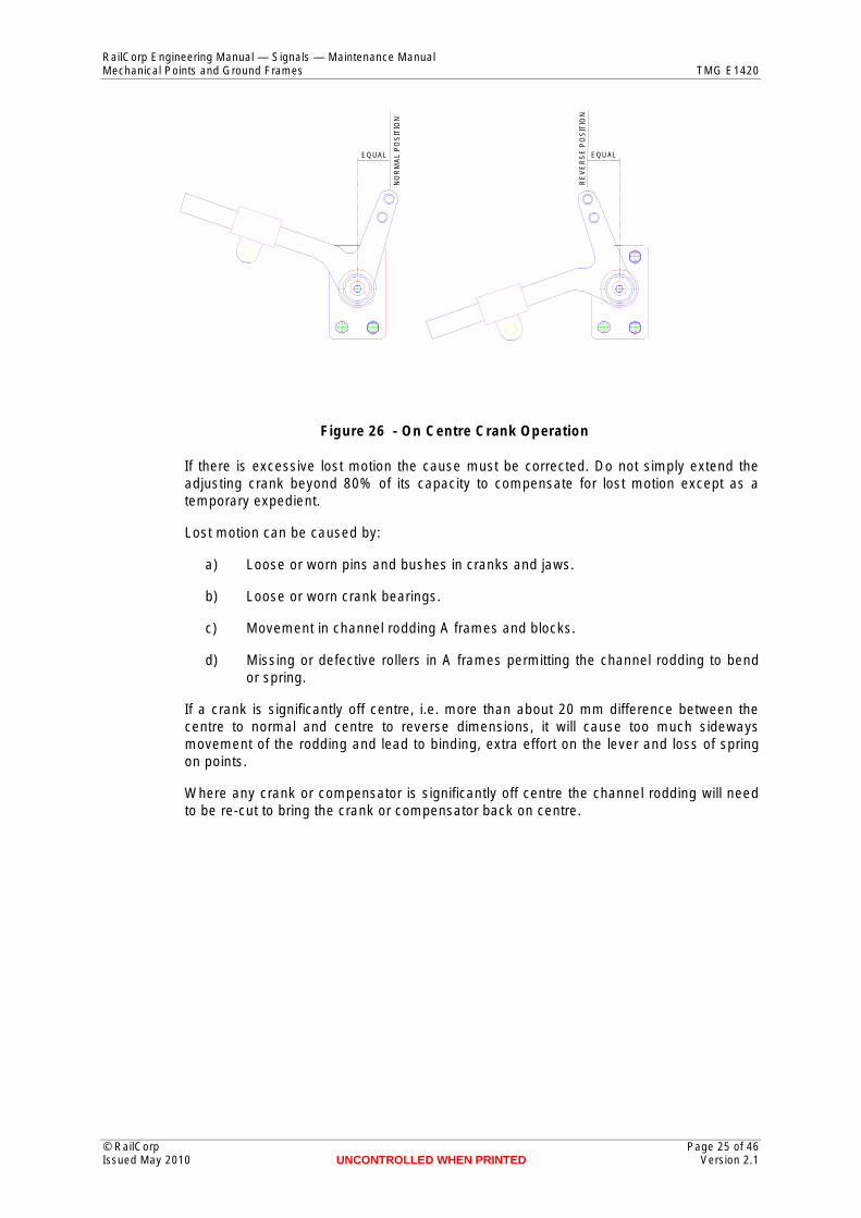
Check that cranks and compensators are operating on centre or close to on centre.
© RailCorp Page 24 of 46 Issued May 2010 UNCONTROLLED WHEN PRINTED Version 2.1
Mechanical Points and Ground Frames TMG E1420
EQUAL
OO
RM
AL
PS
II
TO
N
Figure 26 - On Centre Crank Operation
If there is excessive lost motion the cause must be corrected. Do not simply extend the adjusting crank beyond 80% of its capacity to compensate for lost motion except as a
Loose or worn pins and bushes in cranks and jaws. R
RailCorp Engineering Manual — Signals — Maintenance Manual
UNCONTROLLED WHEN PRINTED
R
EQUAL
N
EE
EV
SP
OS
II
TO
N
Loose or worn crank bearings.
Movement in channel rodding A frames and blocks.
Missing or defective rollers in A frames permitting the channel rodding to bend
If a crank is significantly off centre, i.e. more than about 20 mm difference between the centre to normal and centre to reverse dimensions, it will cause too much sideways movement of the rodding and lead to binding, extra effort on the lever and loss of spring
Where any crank or compensator is significantly off centre the channel rodding will need to be re-cut to bring the crank or compensator back on centre.
temporary expedient.
Lost motion can be caused by:
a)
b)
c)
d) or spring.
on points.
© RailCorp Page 25 of 46 Issued May 2010 Version 2.1
RailCorp Engineering Manual — Signals — Maintenance Manual Mechanical Points and Ground Frames TMG E1420
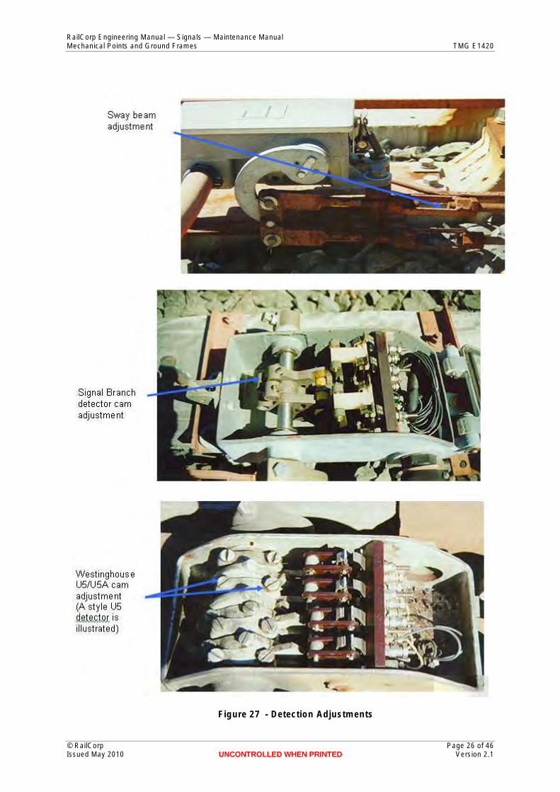
Figure 27 - Detection Adjustments
© RailCorp Page 26 of 46 Issued May 2010 UNCONTROLLED WHEN PRINTED Version 2.1

RailCorp Engineering Manual — Signals — Maintenance Manual Mechanical Points and Ground Frames TMG E1420
3.4 Points
3.4.1 Trailing points
Test the “spring” on the points.
For the end of points closest to the machine, spring may be checked by steadily pulling the lever to the normal or reverse positions until the switch lays up against the stockrail without any pressure. At this point the lever should be approximately the thickness of the catchrod block out of the normal or reverse notch.
For the end of a crossover or the catchpoint furthest from the machine, it is better to check the points themselves by levering the switch away from the stockrail with a 600 mm pinch bar or similar. This should not require undue effort and the switch should return firmly to the stockrail when pressure is released.
If the switch cannot be moved off the stockrail or requires excessive force to move, the spring is too great.
Adjust spring at the bobbins on the front rod if required.
Test the electrical detector settings by placing a 4.8mm gauge between the switch and stockrail 75 to 100mm from the tip of the switch. Detector contacts should be open.
Repeat with a 3.2mm gauge. Detector contacts should be at the point of making or be just made.
Repeat with a 1.6mm gauge. Detector contacts should be made.
Adjust the detector rods on slide type detectors such as the ML and Westinghouse HM2/3 or the sway beam or cams on Signal Branch and Westinghouse U5/5A detectors if necessary (Figure 27).
Repeat all tests for the reverse position.
3.4.2 Facing Points
Carry out the same tests as for trailing points. Note that the facing point lock or Westinghouse HDLM point locking must be disengaged to carry out spring tests.
In addition test the facing point lock or Westinghouse HDLM point locking by placing a 3.2mm gauge between the switch and stockrail immediately behind the lock rod. It should not be possible to engage the lock.
Repeat with a 1.6mm gauge. It should now be possible to engage the lock, although it may rub against the side of the lock rod block.
Adjust detector rods if necessary on Westinghouse HDLM detectors (if fitted).
Adjust the lock rod if necessary. Repeat all tests for the reverse position.
Test the facing point lock detection (if fitted). Detector contacts should not make until the plunger has completed 2/3 of its stroke (130 to 140 mm of the 200 mm stroke) to the engaged position.
Test the Westinghouse HDLM point lock detection (if fitted).
Adjust the turnbuckle at the detector crank if required.
© RailCorp Page 27 of 46 Issued May 2010 UNCONTROLLED WHEN PRINTED Version 2.1

RailCorp Engineering Manual — Signals — Maintenance Manual Mechanical Points and Ground Frames TMG E1420
4 On System Maintenance
4.1 Tasks The tasks to be carried out for on system maintenance of ground frames are as listed in the Signalling Technical Maintenance Plan Service Schedules SC 00 51 00 00 SS, Schedule SS 05 21 02 and for channel rodding and points in Schedule SS 07 34 01.
The intervals at which these tasks are to be carried out are as specified in the baseline Signalling Technical Maintenance Plan SC 00 51 00 00 MP or in approved tailored TMPs which apply to the line or section in which the equipment is located.
4.2 Tools and Materials The following tools and materials are recommended for carrying out the on systemmaintenance tasks:
Adjustable spanners 200, 300 and 375mm.
Two each 24 and 30mm ring/open end spanners (or socket set).
Ball peen hammer.
Podger.
Combination pliers 200mm.
Forked spanner for Annett lock cover.
Shovel.
Brush cutter (petrol powered).
Lubricating Oil SAE 80-90.
Long nose pliers 160mm.
600 grade wet and dry paper.
Screwdrivers flat blade 200, 250 and 300mm.
Cheese cloth.
Point Lock and detection gauge with 1.6, 3.2 and 4.8mm blades.
4.3 Instructions
4.3.1 Ground frames
Examine the condition of the frame and floor plates for any sign of cracking. Pay particular attention to the base of the end frames where they are secured to the foundation. Cracks in cast iron frames cannot be successfully field repaired and these must be replaced if cracked. Steel frames can be repaired by welding.
Check:
That the bolts securing the frame to the foundation are tight and not seriously corroded.
© RailCorp Page 28 of 46 Issued May 2010 UNCONTROLLED WHEN PRINTED Version 2.1

RailCorp Engineering Manual — Signals — Maintenance Manual Mechanical Points and Ground Frames TMG E1420
That the bolts securing the floor plates to the frames, the locking box brackets to the frames and the locking box to the brackets are secure.
That the lever shaft bearing caps are secure and that the lever bearings are secure.
Check that the catchrod handle is properly secured to the lever with split pins installed and spread, that the bolts securing the catchrod box to the lever are secure and that the catchrod engages fully in the notch in the floor plate when in the released position.
Examine the condition of the catch rod block and the floor plate for grooving of the block (to be no more than about 2mm) or rounding off of the edge of the notch in the floor plate.
Check that the bolts securing the Annett lock to the lever are tight, the bolts securing the Annett lock cover are tight and that the key hole cover does not jam in the open position.
Check that split pins are installed and spread in the connections between the levers and the channel rodding.
Remove the locking box cover and clean and lubricate the tappets and slides. During this task removal of the locking is to be avoided.
Replace the locking box cover ensuring that the cover bolt(s) is tight and the cover is secure.
Note:
A dry lubricant may be used in place of oil for locking box lubrication. However this requires that the tappets and locking dogs be removed and the box, tappets and dogs be thoroughly
cleaned with an appropriate solvent to remove oil residue before the dry lubricant is applied. It will then be necessary to carry out
an interlocking test after the locking box is re-assembled.
Figure 28 - Electric Lock Tappet Adjustment
Lubricate the lever bearings and the pins in the catch rod handle and connections to the channel rodding. Wipe any excess oil off the catchrod handle and lever.
© RailCorp Page 29 of 46 Issued May 2010 UNCONTROLLED WHEN PRINTED Version 2.1

RailCorp Engineering Manual — Signals — Maintenance Manual Mechanical Points and Ground Frames TMG E1420
4.3.2 Electric Locks
Examine the condition of the weatherproof cover over the electric lock and ensure that it is not permitting water to enter the lock.
Remove the weatherproof cover and check the security of the bolts securing the lock to the frame, and the extension to the locking tappet (or if mounted opposite to the locking, the lock tappet to the lever).
Examine the air gap between the pole face and the armature and ensure that the stop screw is standing proud of the armature face and that there is a 0.5 mm (0.4 to 0.6 mm) gap between the armature and the pole face when the lock is lifted. Ensure that the locknut on the stop screw is tight.
Lift and drop the lock several times to ensure that the locking dog is dropping cleanly into the hole in the tappet and that it does not rub or ledge on one side of the hole as shown in Figure 28.
Examine the condition of the lock drop contacts and clean if necessary with cheesecloth. If heavy contamination or burning is evident, first clean with 600 grade wet and dry paper, then burnish with cheesecloth.
Check that the contacts do not make until the dog is engaged in the tappet by at least 5mm. Adjust if necessary by carefully bending the spring contact finger.
Clean the contact block and check that wiring connections are secure and insulation is undamaged.
4.3.3 Channel Rodding
Check that “A” frames are secure on the stands and that the stands are secure in the ground. Any stands which are leaning away from vertical or are significantly higher or lower than adjacent stands are likely to be loose in ground.
Check that all rollers are present and that no rollers are twisted due to badly worn or missing axles.
Check that cranks and compensators are secure on the baseplates or foundations and that the baseplates or foundations are not moving in the ground.
© RailCorp Page 30 of 46 Issued May 2010 UNCONTROLLED WHEN PRINTED Version 2.1

RailCorp Engineering Manual — Signals — Maintenance Manual Mechanical Points and Ground Frames TMG E1420
Figure 29 - Crank with sintered bronze main bearing
Lubricate the connections on compensators and cranks and the bearings on older style cranks. Do not lubricate the main bearings on cranks fitted with sintered main bearings, Figure 29.
Clear any potential obstructions away from the vicinity of the channel rodding and cranks.
4.3.4 Points
Check that chair bolts and screw spikes are secure and that there are no bolts or switchstops likely to become dislodged and foul the switch or rodding.
Check that the switches are bearing on, or within 1.5mm of the ‘A’ and ‘B’ chairs.
If possible observe the behaviour of the points under a train to determine whether there is“pumping” around the ‘A’ and ‘B’ timbers or whether the switch is kicking up as wheelspass over the heel.
If permanent way defects are found either correct the defect or report the defect forcorrection by civil staff in accordance with local work instructions.
Check that bolts securing the front rod, back rod, extension pieces and lock rod are tight.
Check that the facing point lock (if fitted) is properly secured and that there is nomovement between the lock and sleeper. Check that the bolts securing the angle crank inthe four foot are tight and that the crank base shows no signs of movement.
Check that all pins are fitted with split pins and that the split pins are properly spread.
Lubricate the facing point lock plunger (if fitted) and cross slide.
Lubricate the lock rod where it passes through the facing point lock (if fitted).
© RailCorp Page 31 of 46 Issued May 2010 UNCONTROLLED WHEN PRINTED Version 2.1

RailCorp Engineering Manual — Signals — Maintenance Manual Mechanical Points and Ground Frames TMG E1420
Lubricate pinned connections at the facing point lock (if fitted), angle crank and detector.
For Signal Branch and Westinghouse U5 detectors, clean the detector and examine the condition of and tension on the contacts. Tension should be sufficient to prevent “bobbing” (opening under passage of a train) but not so high that it leads to grooving in the moving contacts.
Contacts should normally only be burnished with cheesecloth. If heavier cleaning is required, this should be carried out only as a temporary expedient pending replacement of the contact as soon as possible.
For ML, Westinghouse U5A, HM2 and HM3 detectors, clean the detector.
For Westinghouse HDLM point lock and detectors, clean the detector and examine the unit for any signs of damage or case cracking. Ensure all fastenings are tight, especially the sleeper and bedplate fixings, and rodding. Apply grease to the detector and lock slides.
Inspect the lock proving contacts on Westinghouse HDLM point lock and detectors (if fitted). An aerosol spray cleaner for electrical use may be used to clean the contacts or blow off contamination. The contacts are not to be adjusted. Replace the contacts if there is serious evidence of pitting, or they are bent or deformed.
Check that the detector is secure and that there are no signs of movement on the sleeper or baseplate.
5 Fault Diagnosis
5.1 Ground Frame, Channel Rodding and Points Where a fault occurs with a ground frame or the channel rodding drive or the mechanical points, it will be obvious due to the simple open nature of the equipment. Provided that the equipment is correctly installed and not expected to perform beyond it’s capabilities, failures will be due to visible wear, fracture or movement of “A” frame or crank foundations in the ground, stockrail movement at the points or loose fixings and fasteners allowing components to slip out of position.
5.2 Electric Locks There are two failure modes for electric locks, fail to pick up and fail to drop. In both cases, it is possible that the cause of the failure is not directly related to the electric lock but is in the circuitry between the electric lock and the controlling signalling interlocking.
If the lock fails to pick up, first check that there is power at the lock coil. If power is present, check that the locking dog is not jamming in the tappet.
If power is present and there is no indication that the locking dog is jamming then the electric lock itself is defective and must be replaced.
If power is not present, the fault lies in the circuitry between the signalling interlocking and the electric lock and must be traced through the circuits to the electric lock.
If the lock fails to drop and remains fully in the up position, the fault is due either to residual magnetism within the coil or to an extraneous supply maintaining power to the lock circuit.
Provided that the air gap between armature and pole face has been maintained, residual magnetism is unlikely and is even more unlikely to hold the lock up for any length of time.
© RailCorp Page 32 of 46 Issued May 2010 UNCONTROLLED WHEN PRINTED Version 2.1

RailCorp Engineering Manual — Signals — Maintenance Manual Mechanical Points and Ground Frames TMG E1420
If the lock drops only part way then the fault is due to the dog ledgeing on the tappet.
6 Installation
6.1 Ground Frame
6.1.1 Application
The Type G ground frame is suitable for operating the following maximum combinations of points or any lesser combination:
a) A crossover constructed from 60kg rail provided that:
i) The ground frame is placed no more than 5 metres from one end of the crossover.
ii) Neither end of the crossover requires a backdrive.
iii) The two ends of the crossover are not more than 75 metres apart.
b) One end of points plus a catchpoint constructed from 60kg rail. The points may have a backdrive as shown in Figure 30.
c) A single end of tangential points of 190 or 250 metre radius provided that the points are fitted with claw locks. Claw lock installation is covered in the Claw Lock Manual TMG E1343 and TMG E 1344.
d) A 190 or 250 metre tangential crossover provided that a 3 lever machine is used with lever 2 driving the remote end of the crossover and lever 3 driving the closest end. Locking for this machine must be as shown in Figure 31. (Note that no separate point lock is required with claw locks)
e) A crossover plus single catchpoint constructed from 53kg or lighter rail provided the frame is located within 5 meters of one end of the crossover.
Ground frames must not be used to drive:
f) Any crossover which requires backdrives both ends, eg 60kg 9150 switches on 1 in 15 turnouts
g) Any tangential turnout larger than 250 metre radius.
The Type F single lever should not be used for any new applications.
No new installations of ground frames operating claw locks is permissible
© RailCorp Page 33 of 46 Issued May 2010 UNCONTROLLED WHEN PRINTED Version 2.1

RailCorp Engineering Manual — Signals — Maintenance Manual Mechanical Points and Ground Frames TMG E1420
(The backdrive components and connections are identical to those used with electric switch machines).
Figure 30 - Backdrive Fitted to Ground Frame Operated Points
© RailCorp Page 34 of 46 Issued May 2010 UNCONTROLLED WHEN PRINTED Version 2.1

RailCorp Engineering Manual — Signals — Maintenance Manual Mechanical Points and Ground Frames TMG E1420
Figure 31 - Locking for 3 Lever Machine Operating Claw Locks
6.1.2 Location
The ground frame should be located between 3 and 5 metres from the points in the main (or more important) line with the centre line of the closest lever 1830mm from running face, Figure 32.
For a main line crossover the ground frame should be located at the most convenient end taking into account the space available and the nature of the ground onto which the machine is to be mounted.
Wherever possible, the machine should be mounted so that the operator is facing the points worked by the ground frame.
© RailCorp Page 35 of 46 Issued May 2010 UNCONTROLLED WHEN PRINTED Version 2.1

RailCorp Engineering Manual — Signals — Maintenance Manual Mechanical Points and Ground Frames TMG E1420
Figure 32 - Ground Frame Location
Figure 33 - Typical ground frame installation
© RailCorp Page 36 of 46 Issued May 2010 UNCONTROLLED WHEN PRINTED Version 2.1

RailCorp Engineering Manual — Signals — Maintenance Manual Mechanical Points and Ground Frames TMG E1420
Figure 34 - Typical channel rodding installation
Ground frames should not be mounted between tracks unless there is at least 300mm clearance to structure gauge from the closest lever on each side.
Where a track or signalling plan or working sketch shows the location of a ground frame relative to the points, this location should be adhered to unless there is reasonable justification to relocate such as lack of space, bad ground, poor access or obstructions to the channel rodding drive.
Figure 33 and Figure 34 show typical ground frame and channel rodding drive locations.
© RailCorp Page 37 of 46 Issued May 2010 UNCONTROLLED WHEN PRINTED Version 2.1

RailCorp Engineering Manual — Signals — Maintenance Manual Mechanical Points and Ground Frames TMG E1420
Figure 35 - Type G ground frame on concrete slab foundation
6.1.3 Foundations
6.1.3.1 Type E Ground Frame
Type E ground frames should not be used for any new installations.
6.1.3.2 Type G Ground Frame
The original foundation for a Type G ground frame was made from reclaimed rails mounted in pre-cast concrete footings. More recently this built up foundation has been replaced by a concrete slab or concrete slab and steel frame as shown in Error! Reference source not found. and Figure 36. The steel frame may be made up of angle or channel sections.
Handrails should be provided each side of the platform as shown in Error! Reference source not found. and one or two steps to the operating platform, depending on height above ground, are required.
© RailCorp Page 38 of 46 Issued May 2010 UNCONTROLLED WHEN PRINTED Version 2.1

6.2
Topmost hole in lever tail should be approximately 40mm below rail level
= 750 = 900
The Type F single lever should not be used for any new installation.
A foundation similar to the Type G foundation was used for these machines.
Channel rodding should be installed so that the top of the rodding is approximately 25 mm below rail level. This will permit maximum sets of 76mm in connections between the channel rodding and cranks and compensators and 76mm maximum sets where it is
channel rodding at a lower level to ensure that the A frames blocks are secure in the ground. If it is necessary to mount the channel rodding lower, it will not be possible to
extended sleepers and these must be
Determine whether the cranks at the points are to be mounted on extended sleepers or
If a separate stand (or stands) are necessary, determine the position (locate from the tip of the points, or, if the point rods are already installed, from the front rod) and height required, mount the stands and concrete securely into the ground.
If a separate stand is used for each crank it is of benefit to mount both in a single
Determine the position of the compensator(s) and concrete the stand(s) into the ground,
RailCorp Engineering Manual — Signals — Maintenance Manual Mechanical Points and Ground Frames TMG E1420
Handrail
For a 2 lever machine WSteps - width = W, maximumrise 300mm For a 3 lever machine W
H
W
Ground Level
H to suit rail level height above Re-inforced concrete slab 200 minimumthick ground minimum150mmin ground
or legs extended and concreted into ground
Bolt machine to frame with 20 minimumthick hardwood packing between frame and frame
Figure 36 - Type G Foundation
6.1.3.3 Type F Single Lever
6.1.3.4 Westinghouse Ground Frame
Channel Rodding and Cranks
necessary for the run to pass under tracks.
However, in with very high ballast profiles, it may be necessary to install theareas
mount the adjusting cranks at the points on mounted on separate stands.
To install a channel rodding run proceed as follows:
on a separate stand.
concrete foundation.
Figure 37.
© RailCorp Page 39 of 46 Issued May 2010 UNCONTROLLED WHEN PRINTED Version 2.1

RailCorp Engineering Manual — Signals — Maintenance Manual Mechanical Points and Ground Frames TMG E1420
Determine the location of any other cranks required, such as deflecting or elevating cranks and concrete the stands into the ground.
Allow at least 72 hours and preferably 96 hours for concrete curing before the cranks are mounted onto the stands.
Figure 37 - Cranks mounted on separate stands
Install the A frames, stands and foundations at maximum 2 metre centres, ensuring that the A frames are in line (or in a smooth, gentle curve) and are all at the same height relative to rail level.
If necessary, in soft ground or where the concrete block cannot be fully buried, add additional concrete around the block so that it will remain secure and stable and not lift when the channel rodding is used.
Fit the connections (joints) to the ground frame, cranks and compensators.
The channel rodding can be placed in the A frames and fixed to the ground frame but must not be cut to length or drilled for crank or compensator connections until the points equipment has been installed (refer 6.3 below).
Since the closest end of points to the ground frame is normally connected to the channel rodding by a drop lug, Figure 38, it is simpler to commence cutting in the channel rodding at the points furthest from the frame.
Place the ground frame levers at mid stroke, the points at mid stroke and, facing point lock (if fitted) at mid stroke and the compensator(s) at mid stroke.
© RailCorp Page 40 of 46 Issued May 2010 UNCONTROLLED WHEN PRINTED Version 2.1

6.3
RailCorp Engineering Manual — Signals — Maintenance Manual Mechanical Points and Ground Frames TMG E1420
Figure 38 - Drop Lug Connection To Channel Rodding
Measure and cut and/or drill the channel rodding and bolt the joints to the cranks and compensators to the channel rodding with the appropriate sized 12mm or ½ inch hexagon or tee-head bolts.
Check the operation of the channel rodding and points but do not carry out final adjustments or testing at this stage.
Return to the end of points nearest the frame and place the ground frame levers, the points and the facing point lock (if fitted) at mid stroke.
Mark and drill the channel rodding for the lugged fishplates and bolt the fishplates to the channel rodding.
Check the operation of both ends of points and test spring, facing point lock or Westinghouse HDLM point lock and detector adjustments.
Facing Points The following set up procedure assumes that the turnout has been installed in the track and has been ballasted, lined, levelled and tamped. If set up off site, the procedure is essentially the same except that no testing can be carried out and it will be necessary to re-adjust the lock rod, the FPL plunger position (if fitted) and detector rods after the turnout is installed in the track. Note that even if cranks have been set up on centre off site, they may be slightly off centre when the turnout is installed due to minor twisting of the turnout. If fixed length rods have been used, it is not necessary to cut-in new rods if the cranks are within, or can be brought within, ±20mm of centre.
a) Before commencing installation, examine the turnout and ensure that:
i) The correct timbers have been installed (refer to Drawing M10-301. (Note: if cranks are to be mounted on separate stands extended timbers are required only for detectors).
© RailCorp Page 41 of 46 Issued May 2010 UNCONTROLLED WHEN PRINTED Version 2.1

RailCorp Engineering Manual — Signals — Maintenance Manual Mechanical Points and Ground Frames TMG E1420
ii) Chair bolts and studs are tight and studs are not fouling any part of the switch.
iii) Each switch lays up to the stockrail correctly when barred closed and remains against the stockrail when the force is removed. (Note: with dry chairs it will probably be necessary to bar the switch in several places).
iv) With the switch closed against the stockrail, any gap between the tip of the switch and the stockrail is less than 1mm.
v) Note: It is not uncommon for a switch to close up hard just back from the tip but leave a small gap at the tip. This gap, if small, can sometimes be corrected by adjusting the back rod relative to the front rod (i.e. spreading the back rod slightly). Care is required here however, since spreading the back rod may distort the opposite switch. If the gap is more than about 1mm, it cannot be corrected with the signalling equipment and the switch must be crowed.
b) Fit the front and back rods to both switches.
c) Close one switch (usually the normally closed switch) against the stockrail and clamp closed (Note: It is better to use a G-clamp at the rail head rather than a point clip since this will avoid introducing switch roll).
d) Adjust the front and back rods so that the other switch is open 114 – 115mm.
e) Release the clamp and bar the points over and back several times to check how each switch is laying against its stockrail. Adjust the rods as necessary to correct any deficiencies. Make sure to maintain the 114-115mm switch opening.
f) For points locked with a Westinghouse HDLM point lock and detector proceed to step 32. Remove the cover from the facing point lock and remove the plunger and cross slide. Place the facing point lock casting onto the “A” timber with the centre of the lock at a distance of 635mm from running face on the normally closed switch side.
g) Fit the lock rod and extension pieces to each switch. Hand tighten only sufficient bolts to hold the lock rod in position.
h) Align the plunger casting so that at mid stroke it is at right angles to the lock rod and the lock rod is centred in the notch in the lock casting. Note:- If work is carried out on a very cold day, the clearance between the lock rod and the lock casting on the “B” timber side should be decreased by 1-2mm, if carried out on a very hot day this clearance should be increased by 1-2mm.
i) When satisfied the lock casting is correctly positioned mark the four holes to be drilled in the “A”timber.
j) Remove the lock rod and lock casting and drill the four holes 21mm diameter.
k) Bolt the lock casting onto the “A” timber with a 6mm packing plate under the casting.
l) Refit the lock rod and the extension pieces to each switch. (If the switch is drilled and countersunk for it, and if the extension piece provides for it, fit the 7/8 bolt through the lock rod and extension piece).
m) Refit the lock plunger and cross slide to the facing point lock. Bar the points to the normal position and clamp the switch to the stockrail. (Again use a G-clamp at the head of the rail rather than a point clip). Loosen and separate the
© RailCorp Page 42 of 46 Issued May 2010 UNCONTROLLED WHEN PRINTED Version 2.1

RailCorp Engineering Manual — Signals — Maintenance Manual Mechanical Points and Ground Frames TMG E1420
serrated plates on both sides of the lock rod. Move the centre part of the lock rod so that the plunger can be pushed fully home. Move the centre portion of the lock rod back so that the block rests against the side of the plunger. Tighten one bolt in each serration ensuring that the teeth in the serrations are properly engaged.
n) Move the plunger in and out. It should operate with slight binding or be marginally clear. If tight, back off one serration.
o) For points locked one way (normal) proceed to step 17. For points locked both ways withdraw the plunger, remove the clamp, bar the points to the reverse position and clamp the reverse switch closed.
p) Push the plunger home and check its clearance from the block on the lock rod. If adjustment is required, it will be necessary to adjust the reverse side of the lock rod and the switch opening on the front and back rods.
q) Tighten both bolts in each serrated part of the lock rod.
r) Fit the adjustable, insulated, set shackle length to the plunger and to a 250 x 250 angle crank. Place the crank on the A2 timber with the crank arm on centre, the shackle length aligned with the plunger and the plunger at the mid stroke position. Mark and drill the holes for the crank base. Fit the crank base and check that the crank and plunger move freely.
s) For points fitted with an electrical detector, fit the detector and baseplate (detectors and brackets if 2 Signal Branch detectors are used) to the “A” and/or “A1” timber where shown on the points layout. Fit the drop lug to the facing point lock cross slide.
t) Fit the rod to the appropriate crank or slide on the detector(s). Move the points to the normal position and push the lock plunger fully home. Position the crank or slide in the detector so that the relevant contacts (NB the normal contacts in U5, HM3 and ML detectors) are well made. It will be necessary to position the other slides in HM3 and ML detectors so that the roller can fall into the notch. Mark and drill the rod and bolt it to the drop lug on the lock cross slide.
u) Fit the drop lug to the angle crank in the four foot and fit the cradle to the front rod.
v) Where the adjusting cranks are to be attached to the “A2” and “B” timbers place the baseplate between the “A2” and “B” timbers and place the adjusting cranks for the FPL and drive in their approximate positions. If the cranks are to be mounted onto a separate stand or stands refer to Section 6.2.
w) Adjust the clip on each crank to 410mm from crank centre.
x) Place the facing point lock plunger at mid stroke. Place the adjusting crank for the FPL at mid stroke (i.e. fixed arm at right angles to the channel rodding from the interlocking machine) and align the clip with the drop off lug on the crank in the four foot. Align the base of the crank with the baseplate.
y) Withdraw the lock plunger and place the points at the mid position. Place the adjusting crank for the drive at mid stroke and align the clip with the centre of the hole in the cradle. Align the base of the crank with the baseplate.
z) Mark and drill the baseplate and the “A2” and “B” timbers.
aa) Bolt the cranks and baseplate to the timbers.
© RailCorp Page 43 of 46 Issued May 2010 UNCONTROLLED WHEN PRINTED Version 2.1

6.4
RailCorp Engineering Manual — Signals — Maintenance Manual Mechanical Points and Ground Frames TMG E1420
bb) Place the adjusting crank for the drive at mid stroke, fit the driving rod and bobbins into the cradle and fit the 75mm set up joint to the crank. Mark and drill the channel and fit between the driving rod and set up joint.
cc) Move the points to the normal position and place the lock plunger at mid stroke. Place the adjusting crank for the FPL at mid stroke and fit a 75mm set up joint to the crank. Mark and drill the channel and fit between the set up joint and the drop off lug on the angle crank.
dd) Place the FPL lever in the interlocking machine at mid stroke, and all cranks and compensators in the channel rodding lead from the interlocking machine at mid stroke. Fit the appropriate set up joint to the adjusting crank and measure and drill for attachment to the channel rodding.
ee) The FPL may now be adjusted to provide full 200mm travel and to be 20mm clear of the lock rod block with the lever in the reverse position.
ff) For points locked with a facing point lock proceed to step 35. Fit the HDLM detector and baseplate to the “A” and “A1” timbers where shown on the points layout.
gg) Fit the lock rod to each switch and to the lock bar on the HDLM unit. Move the points to the normal position. Adjust the lock bar until the lock bolt falls into position on the lock bar.
hh) Fit the detector rod or rods (2 detector rods where normal and reverse detection is required) to each switch and to the appropriate detector slide on the HDLM unit. Move the points to the normal position and engage the point lock. Adjust the appropriate detector slide until the relevant contacts are well made. Repeat for the reverse position if necessary.
ii) Bar the points to the mid position and place the point lever in the interlocking machine and all cranks and compensators in the channel rodding lead at mid stroke. Fit the appropriate set up joint to the adjusting crank and measure and drill for attachment to the channel rodding.
jj) The points may now be tested for correct operation normal and reverse. Adjust the clip on the adjusting crank to provide 18 to 22mm escapement at the bobbins.
kk) Test the facing point lock or Westinghouse HDLM point lock and detection in accordance with Section 3.
ll) Fit split pins to all turned pins and check that all bolts are tight.
Installation Procedure Trailing Points a) Before commencing installation, examine the turnout and ensure that:
i) The correct timbers have been installed, refer to drawing M10-301. (Note if cranks are to be mounted on separate stands, extended timbers are required only for detectors).
ii) Chair bolts and studs are tight and studs are not fouling any part of the switch.
iii) Each switch lays up to the stockrail correctly when barred closed and remains against the stockrail when the force is removed. (Note: with dry chairs it will probably be necessary to bar the switch in several places).
© RailCorp Page 44 of 46 Issued May 2010 UNCONTROLLED WHEN PRINTED Version 2.1

RailCorp Engineering Manual — Signals — Maintenance Manual Mechanical Points and Ground Frames TMG E1420
iv) With the switch closed against the stockrail, any gap between the tip of the switch and the stockrail is less than 1mm.
Note
It is not uncommon for a switch to close up hard just back from the tip but leave a small gap at the tip. This gap, if small, can
sometimes be corrected by adjusting the back rod relative to the front rod (i.e. spreading the back rod slightly). Care is required
here however, since spreading the back rod may distort the opposite switch. If the gap is more than about 1mm, it cannot be corrected with the signalling equipment and the switch must be
crowed.
b) Fit the front and back rods to both switches.
c) Close one switch (usually the normally closed switch) against the stockrail and clamp closed (Note: It is better to use a G-clamp at the rail head rather than a point clip since this will avoid introducing switch roll).
d) Adjust the front and back rods so that the other switch is open 114 – 115mm.
e) Release the clamp and bar the points over and back several times to check how each switch is laying against its stockrail. Adjust the rods as necessary to correct any deficiencies. Make sure to maintain the 114-115mm switch opening.
f) For points fitted with a mechanical detector (wire lock) refer to Section 2.3.
g) For points fitted with an electrical detector, fit the detector and baseplate (detectors and brackets if 2 signal branch detectors are used) to the “A” and/or “A1” timber where shown on the points layout.
h) Fit the extension pieces to each switch.
i) For a Signal Branch or U5/5A detector bar the points to the mid position and place the detector crank so that the hole in the end of the crank is vertically below the shaft. Fit the sway beam and detector rods and position the sway beam vertically. Mark and drill the detector rods from the extension pieces. Fit the rods to the extension pieces and sway beam. (If round rods with rubber bushes are used, no marking or drilling is required).
j) For ML and HM2/3 detectors bar the points to the normal position and position the slides in the detector so that the normal contacts are just made. Fit the normal detector rod (mark and drill if necessary). Bar the points to the reverse position and repeat for the reverse detector rod.
k) Bar the points to mid stroke and place the adjusting crank for the drive at mid stroke, fit the driving rod and bobbins into the cradle and fit the 75mm set up joint to the crank. Mark and drill the channel and fit between the driving rod and set up joint.
l) Place the point lever in the interlocking machine and all cranks and compensators in the channel rodding lead at mid stroke. Fit the appropriate set up joint to the adjusting crank and measure and drill for attachment to the channel rodding.
m) The points may now be tested for correct operation normal and reverse. Adjust the clip on the adjusting crank to provide 18 to 22mm escapement at the bobbins.
© RailCorp Page 45 of 46 Issued May 2010 UNCONTROLLED WHEN PRINTED Version 2.1

RailCorp Engineering Manual — Signals — Maintenance Manual Mechanical Points and Ground Frames TMG E1420
n) Test the detection in accordance with Section 3.
o) Fit split pins to all turned pins and check that all bolts are tight.
© RailCorp Page 46 of 46 Issued May 2010 UNCONTROLLED WHEN PRINTED Version 2.1