tmc 114 maintenance plan - knapsack gully viaduct · 2017-11-30 · app 7 app 8 railcorp...
TRANSCRIPT

Engi
neer
ing
Man
ual
Engineering Manual Structures
TMC 114
MAINTENANCE PLAN- KNAPSACK GULLY VIADUCT
Version 1.2
Issued July 2010
Owner: Chief Engineer Civil
Approved by: John Stapleton Authorised by: Richard Hitch A/Principal Engineer Chief Engineer Civil Technology & Standards
Disclaimer This document was prepared for use on the RailCorp Network only. RailCorp makes no warranties, express or implied, that compliance with the contents of this document shall be sufficient to ensure safe systems or work or operation. It is the document user’s sole responsibility to ensure that the copy of the document it is viewing is the current version of the document as in use by RailCorp. RailCorp accepts no liability whatsoever in relation to the use of this document by any party, and RailCorp excludes any liability which arises in any manner by the use of this document. Copyright The information in this document is protected by Copyright and no part of this document may be reproduced, altered, stored or transmitted by any person without the prior consent of RailCorp
UNCONTROLLED WHEN PRINTED Page 1 of 53

RailCorp Engineering Manual — Structures Maintenance Plan- Knapsack Gully Viaduct TMC 114
Document control Revision Date of Approval Summary of change
1.2 July, 2010 Changes detailed in chapter revisions
1.1 November, 2009 Reformat throughout; update position titles & references to Chief Engineer to reflect organization changes
1 May, 2009 First issue as a RailCorp document
Summary of changes from previous version Chapter Current Revision Summary of change
Control Pages
1.2 Update version history
Ch 1 1.2 No change
Ch 2 1.2 No change
Ch 3 1.2 No change
Ch 4 1.2 No change
Ch 5 1.2 No change
Ch 6 1.2 No change
Ch 7 1.2 No change
App 1 1.2 No change
App 2 1.2 No change
App 3 1.2 No change
App 4 1.2 No change
App 5 1.2 No change
App 6 1.2 No change
App 7 1.2 Change period and latitude for monitoring of viaduct tasks to make consistent with the specified details in the text
App 8 1.2 SSC 284: update personnel, equipment, references & task details to make consistent with the specified details in the text
SSC 285: update equipment, references & task details to make consistent with the specified details in the text
SSC 286: update personnel, equipment, references & task details to make consistent with the specified details in the text
App 9 1.2 No change
© Rail Corporation Page 2 of 53 Issued July 2010 UNCONTROLLED WHEN PRINTED Version 1.2

RailCorp Engineering Manual — Structures Maintenance Plan- Knapsack Gully Viaduct TMC 114
Contents General....................................................................................................................................... 4Chapter 1
C1-1 Purpose....................................................................................................................................... 4 C1-2 Engineering Investigations And Reports..................................................................................... 4 C1-3 Description Of Structure And Access ......................................................................................... 4 C1-4 References.................................................................................................................................. 5 C1-5 Definitions, abbreviations and acronyms .................................................................................... 5
Technical Maintenance Plans.................................................................................................. 7Chapter 2 C2-1 General ....................................................................................................................................... 7 C2-2 Competency................................................................................................................................ 7 C2-3 Safety Importance....................................................................................................................... 7 C2-4 Management and Reporting .......................................................................................................8 C2-5 Technical Maintenance Plan User Information ........................................................................... 8
Chapter 3 Responsibilities and Authorities........................................................................................... 10
C3-1 General ..................................................................................................................................... 10 C3-2 Bridge Examiner ....................................................................................................................... 10 C3-3 Structures Manager .................................................................................................................. 10 C3-4 Civil Maintenance Engineer ...................................................................................................... 10 C3-5 Chief Engineer Civil .................................................................................................................. 10
Structural Condition ............................................................................................................... 11Chapter 4 C4-1 Load Rating............................................................................................................................... 11 C4-2 Speed........................................................................................................................................ 11 C4-3 Current Condition...................................................................................................................... 11 C4-4 Significant Structural Aspects ................................................................................................... 12
Chapter 5 Maintenance History............................................................................................................... 13
C5-1 General ..................................................................................................................................... 13 C5-2 Investigations ............................................................................................................................ 13 C5-3 Repairs and Strengthening ....................................................................................................... 13
Chapter 6 Inspection and Monitoring Requirements............................................................................ 15
C6-1 Normal Examination Requirements .......................................................................................... 15 C6-2 Additional Examination Requirements...................................................................................... 15 C6-3 Specific Yearly Monitoring ........................................................................................................ 15 C6-4 Documentation.......................................................................................................................... 16 C6-5 Defect Limits and Mandatory Response...................................................................................16 C6-6 Inspection after Earthquake ...................................................................................................... 17
Chapter 7 Maintenance Requirements ................................................................................................... 19
C7-1 Preventive Maintenance ........................................................................................................... 19 C7-2 Exploratory Tasks ..................................................................................................................... 19 C7-3 Corrective Maintenance ............................................................................................................ 19 C7-4 Other Works .............................................................................................................................. 19
Appendix 1 Technical Integrity Report 2005 ............................................................................................ 21
Appendix 2 General Arrangement Drawing.............................................................................................. 26
Appendix 3 Drawing List............................................................................................................................. 27
Appendix 4 Photos ...................................................................................................................................... 28
Appendix 5 Failure Mode Chart ................................................................................................................. 32
Appendix 6 Parapet Monitoring ................................................................................................................. 34
Appendix 7 Technical Maintenance Plan.................................................................................................. 36
Appendix 8 Service Schedules .................................................................................................................. 39
Appendix 9 Examination Reports .............................................................................................................. 43
© Rail Corporation Page 3 of 53 Issued July 2010 UNCONTROLLED WHEN PRINTED Version 1.2

RailCorp Engineering Manual — Structures Maintenance Plan- Knapsack Gully Viaduct TMC 114
Chapter 1 General C1-1 Purpose
This document specifies the Technical Maintenance Plan (TMP) for the Knapsack Gully Viaduct at Lapstone 61.739km on the Main West Line.
The Maintenance Plan specifies preventive maintenance tasks which are either not covered in ESC 100 “Civil Technical Maintenance Plan” or are to be carried out at frequencies other than those specified in ESC 100, and specifies some corrective maintenance tasks. The requirements in ESC 100 apply unless superseded by this TMP.
This document is based on the findings and recommendations of the Knapsack Gully Viaduct Integrity Audit Report 2005 (see Appendix 1) and previous investigation reports.
This document is provided for the use of personnel responsible for programming and implementing the specified tasks.
The maintenance tasks and minimum frequencies defined in this document are mandatory.
C1-2 Engineering Investigations And Reports The following is a list of investigations and reports of the viaduct carried out to date:
1996 Management Plan by RSA (Copy held by Structures Manager, West)
2000 Summary and Recommendation by Rail Access Corporation
2005 Summary and Recommendation Review by Bridges and Structures Services
2005 Technical Integrity Audit Report by Bridges and StructuresMW/TIA/0002), refer to Appendix 1 of this TMP.
Services (Report No.
C1-3 Description Of Structure And Access The viaduct, constructed in 1913 on a 400 m radius, consists of 8 brick arch spans with an overall length of 125 m. The brick abutments and piers are founded on mass concrete spread footings on sandstone bedrock.
Location of Bridge
Figure 1: Location Map
No guard rail exists at present.
Drawings showing General Arrangement (plan and elevation) of the viaduct are attached in Appendix 2.
© Rail Corporation Page 4 of 53 Issued July 2010 UNCONTROLLED WHEN PRINTED Version 1.2

RailCorp Engineering Manual — Structures Maintenance Plan- Knapsack Gully Viaduct TMC 114
A detailed list of drawings for the viaduct is attached at Appendix 3.
Photos of the bridge are in Appendix 4.
C1-3.1 Access To Abutment 1 1. Travel in a westerly direction along the M4 Motorway. Take the Russell Street Exit and then
turn right at the roundabout. 2. Turn left at the traffic lights to the Great Western Highway. Continue about 150m past the rail
overbridge to arrive at the parking area near the steel pipe gate. (This area is known as John Whitton Memorial Place.). Pass through the gate and travel along the unsealed access road towards the Railway line.
3. Pass through the Railway boundary gate on the Upside of the Main West Line and travel along the access road next to the track in the Down direction towards the Viaduct.
4. Gain access to the top of the viaduct and vehicle access under the Arch 1 span.
C1-3.2 Access to Abutment 2 on the Track Approach 1. Proceed to the end of the M4 Motorway. Pass under the steel arch underbridge. 2. Take the next left turn to Lapstone. Turn left in to the unsealed access road about 100m past
the water tank/reservoir. Pass through the boundary gate, and the up side of the Main Western Line.
3. Turn left along access road to arrive at the abutment 2.
C1-3.3 Access to Abutment 2 under the Arch 1. Proceed to the end of M4 Motorway. Pass under the steel arch underbridge. Take the next left
turn to Lapstone at the water tank/reservoir. 2. Take a U-Turn at the water tank. Pass through the under pass of the M4 Motorway. 3. Head back towards Sydney and towards the steel arch underbridge. 4. On approaching the Steel Arch Bridge, be aware of the high speed road traffic, indicate, slow
down and pull up on the left at the stopping/breakdown area. Access to the area under Span 8 of the viaduct can be gained by walking through this gate.
C1-4 References Report No. 848623-R-1 Stanwell Park Viaduct Condition Assessment, Cardno MBK,
2003
Report No 848623-R-2 Stanwell Park Viaduct Design Capacity Review, Cardno MBK, 2004
C1-5 Definitions, abbreviations and acronyms BMS Bridge Management System
Safety Critical An asset/component whose functional failure or secondary Asset/Component damage resulting from the functional failure, either by itself or as
a hidden function in concert with one other failure, will result in an increase in the likelihood of an incident which could involve significant injury to public or staff.
Failure The inability of a system or item to perform its intended function (eg pump water at 1000L/min ± 10L) or satisfy some predetermined conditional attribute (eg rail head profile or gap size).
Safety Critical Task A task that protects against a failure mode (or root cause of a system failure) in a Safety Critical Asset/Component where the failure mode may be applicable to an individual asset/component (e.g. measurement of the gap in a single facing point lock that may drift beyond limits).
© Rail Corporation Page 5 of 53 Issued July 2010 UNCONTROLLED WHEN PRINTED Version 1.2

RailCorp Engineering Manual — Structures Maintenance Plan- Knapsack Gully Viaduct TMC 114
Safety Significant A task that: Task - protects against an eventual possible failure mode (or root
cause of a system failure) in a Safety Critical Asset/Component whose reliability performance is derived from that of a population of asset/components or
- is a quality check on staff performance on safety critical activities.
Engineering Waiver Engineering waivers shall be obtained for non-compliance to any standard. For the TMP, a waiver approved by the relevant Chief Engineer (Track or Civil) is required to allow the completion of a Safety Critical Task or a Safety Significant Task to be delayed beyond the specified task latitude.
No waiver will be issued unless a satisfactory risk mitigation management process is in place.
Regional Waiver Waiver approved by a Civil Maintenance Engineer to allow the completion of a Safety Significant Task to be delayed beyond the specified task latitude.
No waiver will be issued unless a satisfactory risk mitigation management process is in place.
Task Period The minimum frequency at which relevant maintenance tasks should be carried out.
Task Planning The allowed variance of a TMP task from its target date. Latitude Latitudes are for planning purposes, as tasks cannot always be
completed on the actual day due.
The average time between maintenance events should still be in accordance with the specified minimum.
© Rail Corporation Page 6 of 53 Issued July 2010 UNCONTROLLED WHEN PRINTED Version 1.2

RailCorp Engineering Manual — Structures Maintenance Plan- Knapsack Gully Viaduct TMC 114
Chapter 2 Technical Maintenance Plans C2-1 General
The maintenance plan specifies maintenance tasks to ensure this bridge structure remains in a condition commensurate with RailCorp’s safety and reliability objectives.
There are three types of maintenance specified:
− Preventive maintenance
− Exploratory tasks
− Corrective maintenance.
The maintenance plan for this structure was developed after consideration of possible failure modes for the structure. Refer to Appendix 5.
C2-1.1 Preventive maintenance Preventive maintenance is undertaken to keep an item in a specified operating condition through regular maintenance tasks and through systematic examination to detect and prevent potential failures. The former of these includes routine servicing and regular scheduled maintenance based on time or traffic. The latter comprises surveillance examinations, condition monitoring and functional checks. The Technical Maintenance Plan details periods at which preventive maintenance is performed.
C2-1.2 Exploratory tasks Exploratory tasks are undertaken to obtain more detailed information and data on the condition of specified components. It includes additional detailed examinations, specific testing, monitoring, assessment and design investigations and analysis. The Maintenance Plan details tasks and periods at which they are to be performed.
C2-1.3 Corrective maintenance Corrective maintenance is undertaken to restore items to a specified condition by repairing or replacing items. Corrective maintenance is carried out as a result of failures or unsatisfactory conditions detected during preventive maintenance examinations and checks. Corrective maintenance tasks are detailed in the TMP.
C2-2 Competency All maintenance inspection, assessment, monitoring and review functions shall only be carried out by accredited staff.
C2-3 Safety Importance Not all safety related tasks are of equal importance and hence necessitate differing compliance regimes for cost-effective management. RailCorp has divided its assessed safety tasks into two categories, safety critical and safety significant. There are other tasks that are not directly safety related.
The difference in importance between safety critical tasks and safety significant tasks is the failure characteristic of the condition being assessed by the examination task.
The failure characteristics of safety critical tasks are generally rapidly developing and adverse following the breach of defined conditional criteria. There is a significant increase in risk associated with safety critical tasks being extended beyond the specified task period without defined and approved risk mitigation measures in place.
The failure characteristics of safety significant tasks are slower to manifest themselves and less likely to be adverse following the breach of defined conditional criteria.
© Rail Corporation Page 7 of 53 Issued July 2010 UNCONTROLLED WHEN PRINTED Version 1.2

RailCorp Engineering Manual — Structures Maintenance Plan- Knapsack Gully Viaduct TMC 114
C2-4 Management and Reporting Civil Maintenance Engineers shall establish and maintain systems to ensure that the following requirements for the completion of Safety related tasks are met: 1. Safety Critical Tasks shall be completed within the defined planning latitude. An Engineering
Waiver shall be sought for those tasks exceeding the planning latitude. 2. Safety Significant Tasks should be completed within the defined planning latitude.
∼ Civil Maintenance Engineers shall review the compliance of Safety Significant, and other, tasks at the end of each month.
∼ If any task became overdue beyond its planning latitude during the month, but has been completed before the end of the month, it should be reviewed to establish if management action is required to ensure that future inspections will comply with scheduled task requirements.
∼ If any Safety Significant task is overdue beyond its planning latitude at the end of the month, a Regional Waiver shall be established within 7 days. A Regional Waiver may only be authorised up to a period 50% greater than the task period, at which time an Engineering Waiver must be obtained.
WARNING. Failure to secure the appropriate Waiver will require IMMEDIATE (same day) action to
bring the risk back to acceptable levels. This action may include seeking an Engineering Waiver for an extension, removal of the asset from service or placement of service
restrictions on the particular asset.
4. A documented risk mitigation process designed to manage the increase in risk of extending the task period must accompany an application for a waiver.
5. All regional waivers shall be documented. The records, including risk assessment, shall be maintained for audit purposes.
C2-5 Technical Maintenance Plan User Information The TMP table has the following elements:
− Brief description of the maintenance/service to be performed
− Safety Importance
− Applicability of the Service to specified asset configurations or operating environments
− Service Schedule reference
− Minimum task frequencies or periods (including task planning latitudes).
C2-5.1 Service Description This column provides a brief description of preventive, exploratory and corrective maintenance tasks or sets of tasks defined in the Service Schedule.
C2-5.2 Safety Importance Some scheduled examination tasks have been categorised as Safety Critical (C) or Safety Significant (S). Tasks that are unscheduled (ON EVENT tasks) are shown as NA.
C2-5.3 Applicability This column provides information about how maintenance tasks are to be applied across various asset configurations.
C2-5.4 Service Schedule Reference This column provides the alpha-numeric reference code of the Service Schedule applicable for the maintenance tasks.
© Rail Corporation Page 8 of 53 Issued July 2010 UNCONTROLLED WHEN PRINTED Version 1.2

C2-5.5 Period The “Period” column defines the minimum frequency at which relevant maintenance should be carried out for each asset and configuration. Period references include:
ON EVENT Maintenance or examination is to be carried out when the relevant event occurs
Any reduction in the minimum recommended frequencies (lengthening time between tasks) shall be authorised, as appropriate, by the Chief Engineer Civil.
C2-5.6 Latitude This column specifies any latitude that may be allowed for scheduling purposes. The average time between maintenance events should still be in accordance with the specified minimum.
Latitudes are generally expressed in days. That is, a task with a period of 4 months and scheduling latitude of 12 days should be completed within a period of 120 days + or - 12 days.
RailCorp Engineering Manual — Structures Maintenance Plan- Knapsack Gully Viaduct TMC 114
© Rail Corporation Page 9 of 53 Issued July 2010 UNCONTROLLED WHEN PRINTED Version 1.2

RailCorp Engineering Manual — Structures Maintenance Plan- Knapsack Gully Viaduct TMC 114
Chapter 3 Responsibilities and Authorities C3-1 General
District management is responsible for ensuring that the examination, assessment and repair of this structure are carried out by competent persons in accordance with this Manual, TMC 301 “Structures Examination” and TMC 302 “Structures Repair”.
The respective responsibilities of personnel in the implementation of this Maintenance Plan are detailed below.
C3-2 Bridge Examiner The Bridge Examiner is responsible for tasks specified in TMC 301 and for the following additional tasks:
− Earthquake examination of components as specified in this Maintenance Plan.
C3-3 Structures Manager The Structures Manager is responsible for tasks specified in TMC 301 and for arranging the following additional tasks:
− Survey monitoring of parapets
− Monitoring of Span 5 longitudinal crack
− Monitoring of spandrel wall movement between arches 4 and 5
− Routine maintenance
− Steelwork maintenance
− Risk analysis
− Upgrade access road to Span 5
− Design of remedial work
− Monitoring system for the stress bar
− Load rating
− Increase wall height
− Install new refuges
− Removable weather protection cap.
C3-4 Civil Maintenance Engineer The Civil Maintenance Engineer is responsible for tasks specified in TMC 301 and for the following additional tasks:
− Ensuring that preventive maintenance, exploratory tasks, corrective maintenance and other work specified in this Maintenance Plan is carried out.
− Ensuring that management and reporting requirements specified in C2-4 are carried out for the tasks specified in this Maintenance Plan.
C3-5 Chief Engineer Civil The Chief Engineer Civil is responsible for tasks specified in TMC 301 and for the following additional tasks:
− Allocation of Civil Engineers to review and update this Maintenance Plan every three (3) years.
© Rail Corporation Page 10 of 53 Issued July 2010 UNCONTROLLED WHEN PRINTED Version 1.2

RailCorp Engineering Manual — Structures Maintenance Plan- Knapsack Gully Viaduct TMC 114
Chapter 4 Structural Condition C4-1 Load Rating
The viaduct carries freight and passenger trains on the Main West lines, on a curved alignment with a radius of 400 m.
There has not been any structural analysis undertaken to determine the load capacity of Knapsack Gully Viaduct. However, the results of the structural analysis of Stanwell Park Viaduct (with a similar structure) can be used to provide an estimate.
The load capacity of Stanwell Park Viaduct is 300-A-12 + Impact at 40km/hour on both tracks, which is equivalent to Class 81 locomotives with 100t coal wagons at 45 km/hour or Tangara at 70 km/hour.
The following issues are relevant when Knapsack Gully (KG) and Stanwell Park (SP) are compared:
− Critical load case: Resistance of piers to lateral load.
− Track curvature: KG = 400 mm, SP = 240 m.
− Maximum pier height: KG = 27 m, SP = 20 m.
Considering these factors, the load capacity of Knapsack Gully is at least equal to that of Stanwell Park.
C4-2 Speed The speed on the bridge is:
Up Main: 40/60MU i.e. 60 km/hr for XPT and all multiple unit trains; 40 km/hr for other rail traffic.
Down Main: 75/80 i.e. 75 km/hr for freight & normal passenger and 80 km/hr for XPT.
Any maintenance involving the use of Dynamic Track Stabilisers or the TLM over the viaduct is subject to special restrictions.
C4-3 Current Condition The following defects have been identified. Refer to the photos in Appendix 1.
C4-3.1 Arch brickwork All spans: General hairline cracks with water seepage.
Span 5: Longitudinal cracking and movement on the Up side crown. Relative movement of crack is monitored with a scaled bar across the crack, current crack maximum width is 40 to 50 mm.
Span 7: Crack across arch at ¾ height with water seepage.
C4-3.2 Spandrel Wall Between Arch No. 4 and 5: Cracked with outward movement.
C4-3.3 Parapet Wall All spans: Movement and cracking reported since 1985.
At No. 1 refuge: About 10 m from refuge, vertical crack along and across the depth of the wall.
C4-3.4 Brickwork All spans: Stains on the brickwork due to the drainage discharge from the deck.
C4-3.5 Stress Bars Down Side of All spans: Severe to moderate corrosion of the ends of the exposed stress bars.
© Rail Corporation Page 11 of 53 Issued July 2010 UNCONTROLLED WHEN PRINTED Version 1.2
C4-3.6 OHWS All: Moderate corrosion of supporting structures
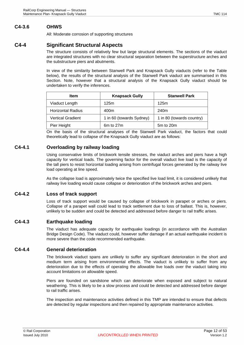
C4-4 Significant Structural Aspects The structure consists of relatively few but large structural elements. The sections of the viaduct are integrated structures with no clear structural separation between the superstructure arches and the substructure piers and abutments.
In view of the similarity between Stanwell Park and Knapsack Gully viaducts (refer to the Table below), the results of the structural analysis of the Stanwell Park viaduct are summarised in this Section. Note, however that a structural analysis of the Knapsack Gully viaduct should be undertaken to verify the inferences.
RailCorp Engineering Manual — Structures Maintenance Plan- Knapsack Gully Viaduct TMC 114
Item Knapsack Gully Stanwell Park
Viaduct Length 125m 125m
Horizontal Radius 400m 240m
Vertical Gradient 1 in 60 (towards Sydney) 1 in 80 (towards country)
Pier Height 6m to 27m 5m to 20m On the basis of the structural analyses of the Stanwell Park viaduct, the factors that could theoretically lead to collapse of the Knapsack Gully viaduct are as follows:
C4-4.1 Overloading by railway loading Using conservative limits of brickwork tensile stresses, the viaduct arches and piers have a high capacity for vertical loads. The governing factor for the overall viaduct live load is the capacity of the tall piers to resist horizontal loading arising from centrifugal forces generated by the railway live load operating at line speed.
As the collapse load is approximately twice the specified live load limit, it is considered unlikely that railway live loading would cause collapse or deterioration of the brickwork arches and piers.
C4-4.2 Loss of track support Loss of track support would be caused by collapse of brickwork in parapet or arches or piers. Collapse of a parapet wall could lead to track settlement due to loss of ballast. This is, however, unlikely to be sudden and could be detected and addressed before danger to rail traffic arises.
C4-4.3 Earthquake loading The viaduct has adequate capacity for earthquake loadings (in accordance with the Australian Bridge Design Code). The viaduct could, however suffer damage if an actual earthquake incident is more severe than the code recommended earthquake.
C4-4.4 General deterioration The brickwork viaduct spans are unlikely to suffer any significant deterioration in the short and medium term arising from environmental effects. The viaduct is unlikely to suffer from any deterioration due to the effects of operating the allowable live loads over the viaduct taking into account limitations on allowable speed.
Piers are founded on sandstone which can deteriorate when exposed and subject to natural weathering. This is likely to be a slow process and could be detected and addressed before danger to rail traffic arises.
The inspection and maintenance activities defined in this TMP are intended to ensure that defects are detected by regular inspections and then repaired by appropriate maintenance activities.
© Rail Corporation Page 12 of 53 Issued July 2010 UNCONTROLLED WHEN PRINTED Version 1.2

RailCorp Engineering Manual — Structures Maintenance Plan- Knapsack Gully Viaduct TMC 114
Chapter 5 Maintenance History C5-1 General
The viaduct performed satisfactorily until 1985 when the cracking and movement in the Up side parapet wall and the crown of arch No. 5 were observed. These defects were attributed to the passage of 100 t coal wagons and the gradual raising of the track.
C5-2 Investigations C5-2.1 Fill material
Investigation of the fill material below the track was carried out during 1988/89. Contrary to the original design drawing, the fill material was found to consist of a mixture of rock and clay.
C5-2.2 Photogrammetric Survey Between 1990 and 1992, a photogrammetric survey was undertaken by BHP. The survey, limited to the longitudinal direction, indicated minor movements, which were within the expected range.
C5-3 Repairs and Strengthening 1985 - 1986 − Installation of horizontal tie bars. As a result of the cracking and movement at the crown of
arch No 5, horizontal mild steel tie bars, spanning across the width of the bridge, were installed approximately 600mm below the rail level to reduce further widening of the cracks.
− Monitoring of parapet movement by installing survey marks
− Grouting of several cracks with epoxy
− Monitoring of ground movement. Due to the parapet cracking and concerns on the geological conditions, particularly the effect of sloping bedding planes, of the foundation, several holes were bored for monitoring ground movement by inclinometer. The monitoring indicated that there was no ground movement.
− Speed restriction of 20km/hour for freight train.
1988 - 1989 − Installation of horizontal ‘VSL’ stress bar and vertical rods. Following an assessment of the
crack and the stability of the Up parapet wall, 32 mm diameter horizontal ‘VSL’ stress bars were installed across the width of the bridge for the full length of the viaduct (2 off at 2 m centres at piers and 2 off at 3 m centres at mid spans). In addition, the Up parapet was secured to the deck with vertical rods.
1990 − Inspection after the Newcastle earthquake
− Re-stressing of stress bars and installation of a longitudinal concrete protection beam on the Up side ends of the bars.
− Monitoring of ground movement at the No. 2 abutment. Due to concerns associated with the proximity of excavation behind the No. 2 abutment (for the construction of an underbridge over the M4 expressway), an inclinometer hole was bored through the No. 2 abutment. Regular monitoring during the excavation did not reveal any movement.
1992 − Replacement of timber sleepers with concrete sleepers as part of the Blue Mountain Line
upgrading
1995 − Replacement of concrete sleepers due to a derailment
© Rail Corporation Page 13 of 53 Issued July 2010 UNCONTROLLED WHEN PRINTED Version 1.2

RailCorp Engineering Manual — Structures Maintenance Plan- Knapsack Gully Viaduct TMC 114
− The derailment did not cause any structural damage to the viaduct.
− The track was lowered to design level.
2000 − Speed restriction for freight train lifted to 40km/hour
2001 − Rail height warning signs installed
2003 − Several OHWS bases rebuilt, or repaired or repainted
− Fabreeka rail pads installed on the up line to reduce vibration effects on the brickwork.
© Rail Corporation Page 14 of 53 Issued July 2010 UNCONTROLLED WHEN PRINTED Version 1.2

RailCorp Engineering Manual — Structures Maintenance Plan- Knapsack Gully Viaduct TMC 114
Chapter 6 Inspection and Monitoring Requirements C6-1 Normal Examination Requirements
The following tasks are to be carried out in accordance with ESC 100 “Civil Technical Maintenance Plan”:
− Detailed structures examination
− Visual structures examination
− Special examinations
− Structural bridge assessment.
A close-up visual examination in accordance with TMC 301 is to be made of all the structural components of this bridge during detailed examination.
C6-2 Additional Examination Requirements The additional examination requirements for Knapsack Gully Viaduct are detailed below and documented in Appendix 7 “Technical Maintenance Plan – Knapsack Gully Viaduct” and Appendix 8 “Service Schedules”.
Following an earthquake or any other unforeseen event, a 'special examination' shall be undertaken.
This examination schedule shall be reviewed after any recorded ground movements approaching the specified intervention levels; any earthquake event greater than Richter magnitude 5.5 or any change in operating regime.
C6-3 Specific Yearly Monitoring C6-3.1 Parapet Lateral Distance Along Viaduct (By Survey)
The relative movements of the Up and Down parapet walls at mid spans and above piers are monitored yearly. With a clear distance between the parapets in the range of 7.8 and 8.0m, the latest survey measurement, taken in July 2006, indicated a maximum difference of 2mm when compared to 2000. The results are shown graphically in Appendix 6 and suggest that there has been an insignificant relative movement between the Up and Down parapets during the last 6 years. Since relative movement is possible due to accidental or overloading of the deck and parapet, the yearly monitoring should continue.
The Civil Maintenance Engineer is responsible for the yearly monitoring. The graphs in Appendix 6 should be updated as results become available.
C6-3.2 Longitudinal Crack On Up Side Of Span 5 C6-3.2.1 Crack widening at the crown
The relative widening of the crack has been monitored for some time using binoculars to view a scaled bar across the crack in the vicinity of the crown. The insignificant widening of the crack, currently 40mm-50mm at its maximum location, during the last 10-15 years strongly suggests that the remedial works undertaken between 1985 and 1992 have been successful in inhibiting further widening.
The crack width monitoring should continue. Due to the criticality of this defect and the need to undertake close visual examinations, consideration should be given by 2009 to erect permanent scaffolding for monitoring at close range. Alternatively, strain gauges could be considered to remotely monitor the gap in real time.
© Rail Corporation Page 15 of 53 Issued July 2010 UNCONTROLLED WHEN PRINTED Version 1.2

RailCorp Engineering Manual — Structures Maintenance Plan- Knapsack Gully Viaduct TMC 114
C6-3.2.2 Crack lengthening There has been limited reporting associated with the crack characteristics in the longitudinal direction and no information on the extent and propagation of the crack during the last 15 years is available.
The longitudinal extent of the crack (with associated crack widths at 15-20 locations) should be measured and recorded on a developed plan of span 5 arch by 2009. This can only be achieved by accessing the crack at close range.
C6-3.3 Movement Of Spandrel Wall Between Arch No. 4 And No. 5 The cracked spandrel wall with the localised outward movement of a section of the wall between arch No 4 and No. 5 has been reported for some time. A close visual examination should be undertaken by 2009 and the extent, profile and outward movement of the crack measured. The crack should be monitored yearly and a sketch, showing the essential features of the crack, should be prepared as a basis for yearly comparison.
C6-4 Documentation Examination and monitoring results are to be documented in the Bridge Management System using the examination report proformas in Appendix 9.
The report format has been developed to act as a prompt for areas to be examined and also to permit recording of defect dimensions so that any changes in defect characteristics over time can be detected.
The Examination Report is comprised of:
− Sheets 1 to 5 for recording general comments on defects associated with the various viaduct elements
− Sheets 6 to 10 for recording defect dimensions.
The Structures Manager shall enter all configuration data, identified defects and any changes in defect condition in the Bridge Management System and TEAMS III.
The viaduct is to be managed like all bridges in the network. Defects shall be recorded with repair priority assigned and actions taken accordingly. Depending on criticality, defects are listed in Weekly Summary of Exceedents.
C6-5 Defect Limits and Mandatory Response C6-5.1 General
Specific defect limits and mandatory responses have been determined for Knapsack Gully Viaduct.
C6-5.2 Ground Movements In the mid 1980’s, due to concerns on the geological conditions that could have an adverse impact on the viaduct foundation, several holes were bored for monitoring ground movement by inclinometer. No movement was detected and the monitoring was discontinued after several years. Similarly ground movement was measured by inclinometer on the up side of the viaduct and no movement was found.
Sydney Water have been drilling and taking water from aquifers about 400 m away from the viaduct. This could have possible impact on ground movement. RailCorp should be named as an interested party and be kept informed of the extent and nature of the works and any possible effects due to the actions of Sydney Water.
In the future, consideration should be given to measuring any differential ground movement, including vertical and lateral subsidence, at the piers and abutments. The monitoring of survey marks (in the ground and on the structure) over a period of time, in combination with inclinometers could be used to detect ground movement.
© Rail Corporation Page 16 of 53 Issued July 2010 UNCONTROLLED WHEN PRINTED Version 1.2

RailCorp Engineering Manual — Structures Maintenance Plan- Knapsack Gully Viaduct TMC 114
C6-5.3 Cracks The following limits apply to new cracks observed at the structural members of the structure, i.e. arches, spandrels or piers. Whilst the parapets are not structural members, new cracking might indicate structure deformation.
The limits also apply to changes in existing cracks. For example, if an existing crack in a brick arch is 5 mm wide by 600 mm long and is observed at the next inspection to have grown to 5 mm wide by 1700 mm long then the intervention level of crack change of 5 mm by 1000 mm will have been exceeded and the mandatory response will need to be implemented.
Cracks in Members
Intervention Level
Mandatory Response
Crack in brick Arches
5mm by 1000mm long
Impose speed restriction 10km/h, investigate, advise Chief Engineer, Civil within two days
Crack in brick Arches
10mm by 2000mm long
Close bridge for traffic, investigate, advise Chief Engineer, Civil within one day
Cracks in brick Spandrels
10mm by 500mm long
Impose speed restriction 10 km/hr, investigate, advise Chief Engineer, Civil within two days
Cracks in brick Spandrels
20mm by 1000mm long
Close bridge for traffic, investigate, advise Chief Engineer, Civil within one day
Cracks in brick Piers
10mm by 1000mm long
Impose speed restriction 10km/h, investigate, advise Chief Engineer, Civil within two days
Cracks in brick Piers
20mm by 2000mm long
Close bridge for traffic, investigate, advise Chief Engineer, Civil within one day
Crack in parapet 5mm by 500mm long
Advise Chief Engineer, Civil within seven days, investigate
Crack on upside of Arch 5 (Existing Crack)
5mm wide or 250mm long
Impose speed restriction 10km/h, investigate, advise Chief Engineer, Civil within two days
Crack on upside of Arch 5 (Existing Crack)
10mm wide or 500mm long
Close bridge for traffic, investigate, advise Chief Engineer, Civil within one day
Crack in Spandrel Wall between Arch No. 4 and 5
Outward movement = 3mm
Impose speed restriction 10 km/hr, investigate, advise Chief Engineer, Civil within two days
Crack in Spandrel Wall between Arch No. 4 and 5
Outward movement = 6mm
Close bridge for traffic, investigate, advise Chief Engineer, Civil within one day
Table 1 Crack Limits
All other defects shall be treated as per RailCorp Standards.
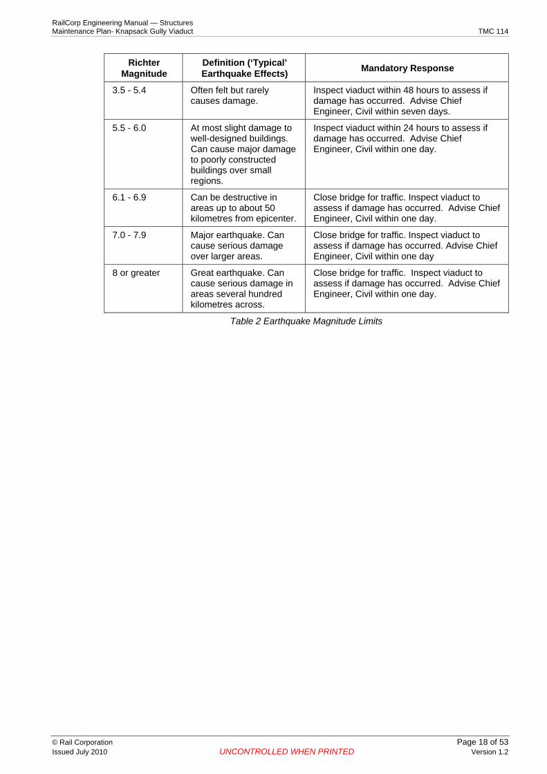
C6-6 Inspection after Earthquake If an earthquake affects the Knapsack Gully viaduct site, action shall be taken according to the table below based on the Richter Magnitude at the Knapsack Gully site.
There is no direct relationship between Earthquake loading and Richter scale. The responses are based on engineering judgment applied conservatively.
Richter Magnitude
Definition (‘Typical’ Earthquake Effects) Mandatory Response
Less than 3.5 Generally not felt, but recorded.
No action required.
© Rail Corporation Page 17 of 53 Issued July 2010 UNCONTROLLED WHEN PRINTED Version 1.2
RailCorp Engineering Manual — Structures Maintenance Plan- Knapsack Gully Viaduct TMC 114
Richter Magnitude
Definition (‘Typical’ Earthquake Effects) Mandatory Response
3.5 - 5.4 Often felt but rarely causes damage.
Inspect viaduct within 48 hours to assess if damage has occurred. Advise Chief Engineer, Civil within seven days.
5.5 - 6.0 At most slight damage to well-designed buildings. Can cause major damage to poorly constructed buildings over small regions.
Inspect viaduct within 24 hours to assess if damage has occurred. Advise Chief Engineer, Civil within one day.
6.1 - 6.9 Can be destructive in areas up to about 50 kilometres from epicenter.
Close bridge for traffic. Inspect viaduct to assess if damage has occurred. Advise Chief Engineer, Civil within one day.
7.0 - 7.9 Major earthquake. Can cause serious damage over larger areas.
Close bridge for traffic. Inspect viaduct to assess if damage has occurred. Advise Chief Engineer, Civil within one day
8 or greater Great earthquake. Can cause serious damage in areas several hundred kilometres across.
Close bridge for traffic. Inspect viaduct to assess if damage has occurred. Advise Chief Engineer, Civil within one day.
Table 2 Earthquake Magnitude Limits
© Rail Corporation Page 18 of 53 Issued July 2010 UNCONTROLLED WHEN PRINTED Version 1.2

RailCorp Engineering Manual — Structures Maintenance Plan- Knapsack Gully Viaduct TMC 114
Chapter 7 Maintenance Requirements C7-1 Preventive Maintenance
Scheduled preventive maintenance tasks are detailed in Appendix 7 “Technical Maintenance Plan – Knapsack Gully Viaduct”.
C7-2 Exploratory Tasks Exploratory tasks are detailed in Appendix 7 “Technical Maintenance Plan – Knapsack Gully Viaduct”.
C7-3 Corrective Maintenance C7-3.1 General
Bridge examination reports detail the scope of maintenance work required for Knapsack Gully Viaduct.
The following general maintenance activities are likely to be required over the remaining life of the viaduct. The programme for these activities will depend on the observed frequency of recurrence of the maintenance issue.
− Monitor ballast depth to avoid gradual build up of excessive ballast
− Ensure that warning signs (regarding track level) are visible
− Remove local track depressions at abutments to reduce impact effects on viaduct
− Clear deck drainage systems
− Repoint joints in brickwork where severe mortar loss has occurred
− Seal cracks in brickwork to prevent dirt penetration and plant growth
− Remove plant growth from brickwork
− Repair or replace deteriorated safety handrails and walkways.
This work is detailed in Appendix 7.
Maintenance programmes to carry out this work shall be developed and implemented in a timely manner to prevent further deterioration of bridge condition.
C7-3.2 Brickwork Members Maintenance is to be done on an “as needed” basis, and no defined routine maintenance tasks are required. Brickwork structures are considered to be basically maintenance free under normal circumstances.
C7-3.3 Steel Members Maintenance of the OHWS steelwork and support brackets, exposed stress bar and anchor plate is to be carried out by June 2009 and in accordance with RailCorp’s Structures Repair Manual.
The refuges shall be inspected for structural integrity and the safety of personnel, in particular with regards to its connection to the spandrel wall.
C7-4 Other Works The access road leading to the area underneath Span 5 should be upgraded and widened to allow the entry and use of vehicle mounted boom lifts for close visual examinations. A design should be produced to stabilise the area around the creek with gabions and concrete to support the weight of the vehicles.
The works described below shall be carried within the time frame shown.
© Rail Corporation Page 19 of 53 Issued July 2010 UNCONTROLLED WHEN PRINTED Version 1.2

RailCorp Engineering Manual — Structures Maintenance Plan- Knapsack Gully Viaduct TMC 114
Work Completion
Perform risk analysis on the need to install guardrails for both tracks December 2009.
Upgrade access road leading to Span 5 to allow vehicle mounted boom lifts to be used
Design by June 2009
Installation by June 2010
Close visual examination of the Upside of Span 5 arch to design remedial work
Examination by June 2010.
Remedial work by June 2011.
Research, develop, trial and commission a monitoring system for the stress bar
Development by Dec 2010
Trial by Dec 2011
Commission by June 2012
Perform a load rating for track maintenance machines Complete by Dec 2008
Increase height of parapet wall at refuges on the Up side.
Design by June 2009
Installation by June 2010
Install new refuges at alternate piers and staggered to those on the Up Side.
Design by June 2010.
Design to consider implications of minimum warning time requirements.
Installation, if required, by June 2011
Removable weather protection cap to the stress bar and anchor plate on the Down Side
Design by June 2009
Installation by June 2010
Table 3 Future Works Program
© Rail Corporation Page 20 of 53 Issued July 2010 UNCONTROLLED WHEN PRINTED Version 1.2
RailCorp Engineering Manual — Structures Maintenance Plan- Knapsack Gully Viaduct TMC 114
Appendix 1 Technical Integrity Report 2005
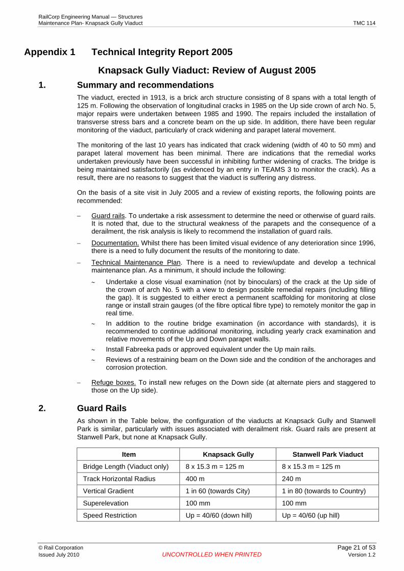
Knapsack Gully Viaduct: Review of August 2005 1. Summary and recommendations
The viaduct, erected in 1913, is a brick arch structure consisting of 8 spans with a total length of 125 m. Following the observation of longitudinal cracks in 1985 on the Up side crown of arch No. 5, major repairs were undertaken between 1985 and 1990. The repairs included the installation of transverse stress bars and a concrete beam on the up side. In addition, there have been regular monitoring of the viaduct, particularly of crack widening and parapet lateral movement.
The monitoring of the last 10 years has indicated that crack widening (width of 40 to 50 mm) and parapet lateral movement has been minimal. There are indications that the remedial works undertaken previously have been successful in inhibiting further widening of cracks. The bridge is being maintained satisfactorily (as evidenced by an entry in TEAMS 3 to monitor the crack). As a result, there are no reasons to suggest that the viaduct is suffering any distress.
On the basis of a site visit in July 2005 and a review of existing reports, the following points are recommended:
− Guard rails. To undertake a risk assessment to determine the need or otherwise of guard rails. It is noted that, due to the structural weakness of the parapets and the consequence of a derailment, the risk analysis is likely to recommend the installation of guard rails.
− Documentation. Whilst there has been limited visual evidence of any deterioration since 1996, there is a need to fully document the results of the monitoring to date.
− Technical Maintenance Plan. There is a need to review/update and develop a technical maintenance plan. As a minimum, it should include the following:
∼ Undertake a close visual examination (not by binoculars) of the crack at the Up side of the crown of arch No. 5 with a view to design possible remedial repairs (including filling the gap). It is suggested to either erect a permanent scaffolding for monitoring at close range or install strain gauges (of the fibre optical fibre type) to remotely monitor the gap in real time.
∼ In addition to the routine bridge examination (in accordance with standards), it is recommended to continue additional monitoring, including yearly crack examination and relative movements of the Up and Down parapet walls.
∼ Install Fabreeka pads or approved equivalent under the Up main rails. ∼ Reviews of a restraining beam on the Down side and the condition of the anchorages and
corrosion protection.
− Refuge boxes. To install new refuges on the Down side (at alternate piers and staggered to those on the Up side).
2. Guard Rails As shown in the Table below, the configuration of the viaducts at Knapsack Gully and Stanwell Park is similar, particularly with issues associated with derailment risk. Guard rails are present at Stanwell Park, but none at Knapsack Gully.
Item Knapsack Gully Stanwell Park Viaduct
Bridge Length (Viaduct only) 8 x 15.3 m = 125 m 8 x 15.3 m = 125 m
Track Horizontal Radius 400 m 240 m
Vertical Gradient 1 in 60 (towards City) 1 in 80 (towards to Country)
Superelevation 100 mm 100 mm
Speed Restriction Up = 40/60 (down hill) Up = 40/60 (up hill)
© Rail Corporation Page 21 of 53 Issued July 2010 UNCONTROLLED WHEN PRINTED Version 1.2

RailCorp Engineering Manual — Structures Maintenance Plan- Knapsack Gully Viaduct TMC 114
Item Knapsack Gully Stanwell Park Viaduct
Down = 70/75 (up hill) Down = 40/60 (down hill)
Pier Height (below rail) 6 m – 27 m 5 m - 20 m
Guard Rails? No Yes
Travel Direction on Down To Sydney Travel Direction on Up
In accordance with RailCorp standard, guard rails are required for ballast top bridges with any individual span > 20 m. For other spans, a risk assessment should be undertaken to determine whether guard rails are required. Criteria to be considered should include bridge height, span, risk of derailment, track alignment and train speed and density. Note that, there was a derailment in 1995, necessitating the replacement of concrete sleepers.
It is recommended to perform a risk assessment. However due to the structural weakness of the parapets and the consequence of a derailment, it is likely that the assessment would recommend the installation of guard rails. Of the two tracks at Knapsack Gully, the Up track (with a 1 in 60 down hill vertical grade and a 40/60 speed restriction) is more critical.
3. Monitoring Since 1996, in addition to the normal examination requirements as per standards, field personnel performed the following tasks:
− A yearly visual examination by the Civil Maintenance Engineer using binoculars, in particular to monitor the longitudinal crack at the Up side of the crown of arch No. 5 (illustrated below). To date, there has been limited propagation of the crack (note that the crack width is about 40 to 50 mm). In July 2005, photos indicated no signs of movement (without white showing between the red and black marks on the measure stick). To remind maintenance personnel, this critical task is entered in TEAMS 3 under “Survey bridge to take comparative measurement”.
© Rail Corporation Page 22 of 53 Issued July 2010 UNCONTROLLED WHEN PRINTED Version 1.2

RailCorp Engineering Manual — Structures Maintenance Plan- Knapsack Gully Viaduct TMC 114
− The relative movements of the Up and Down parapet walls at mid spans and above piers are monitored yearly. With a clear distance between the parapets in the range of 7.8 and 8.0 m, the latest survey measurement, taken in August 2005, indicated maximum differences of 2 mm and 3 mm respectively when compared to 2004 and 2000.
− To reduce the risk of increasing lateral loads on parapets, warning signs were installed.
Whilst there is no visual evidence of any deterioration since 1996, there is a need to fully document the results of the monitoring and prepare an updated technical maintenance plan.
4. Technical Maintenance Plan As a minimum, the maintenance plan should include the following:
− Down side anchorages to transverse stress bars. The bars are 32 mm diameter VSL in a fully grouted PVC duct. The ends of the bars on the Up side are embedded in a beam, therefore of no concerns.
Up Side Restraining Beam
For the Down side anchorages and bar ends, the 1989 design drawing denotes “protection via an approved Denso wrapping system. Bar ends shall be left with a 200 to 300 mm projection to allow for possible construction of restraining beam”. The need for a restraining beam (similar to that on the Up side) should be reassessed in view of the monitoring results to date. If no beam is required, there is a need to review the condition of the anchorages and corrosion protect.
© Rail Corporation Page 23 of 53 Issued July 2010 UNCONTROLLED WHEN PRINTED Version 1.2

RailCorp Engineering Manual — Structures Maintenance Plan- Knapsack Gully Viaduct TMC 114
Down Side: Exposure of Anchorages to Stress Bars
− Longitudinal crack at the Up side of the crown of arch No. 5. There is a need to undertake a close visual examination of the crack to determine its extent and design possible remedial repairs (including filling the gap). Access to the crack is difficult and it can only be monitored via binoculars, which is less than satisfactory. It is suggested to either erect a permanent scaffolding for monitoring at close range or install strain gauges (of the fibre optical fibre type to remotely monitor the gap in real time).
− Additional Monitoring: In addition to the routine bridge examination (in accordance with standards), it is recommended to continue additional monitoring, including yearly crack examination and relative movements of the Up and Down parapet walls.
− Reduction of vibration loading on Up Main track: It is recommended to install Fabreeka pads or approved equivalent under the Up main rails.
5. Refuge Refuge boxes (900 mm wide by 900 mm deep) at 30 m on the Up side (at alternate piers) were constructed around 1990. They are not in accordance with standards, which call for refuges to be 1500 mm wide by 700 mm deep and located at a maximum spacing of 20 m staggered on both sides. While rectifying the dimensions of the existing refuges (to conform to standards) is not warranted, it is recommended to erect new refuges on the Down side (at alternate piers and staggered to those on the Up side). The height of the existing refuge boxes, at approximately 900 mm, is inadequate (because of the possibility of falling over), therefore it is recommended to increase the height for the new refuges to 1.1 m.
6. Viaduct History The viaduct was built in 1913 and performed satisfactorily until 1985 with the observation of cracking / movement in the Up side parapet wall and the crown of arch No. 5. In 1985-86, horizontal steel bars were installed across the width of bridge, some cracks epoxy grouted, movement of parapets monitored and a permanent speed restriction of 20 Km/hour applied to for freight trains. Further assessments indicated a stability problem and as a result, in 1989, high strength bars were installed across the bridge. In 1990, the horizontal tension bars were re-stressed and a longitudinal concrete beam cast on to the Up ends of the bars. During 1990-92, photogrammetric survey indicated minor movements, which were within expected range. In 1992,
© Rail Corporation Page 24 of 53 Issued July 2010 UNCONTROLLED WHEN PRINTED Version 1.2

RailCorp Engineering Manual — Structures Maintenance Plan- Knapsack Gully Viaduct TMC 114
as part of upgrade of the Blue Mountain Line, timber sleepers were replaced with concrete and track reinstated. In 1995, concrete sleepers were replaced due to derailment.
© Rail Corporation Page 25 of 53 Issued July 2010 UNCONTROLLED WHEN PRINTED Version 1.2

RailCorp Engineering Manual — Structures Maintenance Plan- Knapsack Gully Viaduct TMC 114
Appendix 2 General Arrangement Drawing
Extracted from Cardno MBK drawing No. CV 0129138
© Rail Corporation Page 26 of 53 Issued July 2010 UNCONTROLLED WHEN PRINTED Version 1.2

RailCorp Engineering Manual — Structures Maintenance Plan- Knapsack Gully Viaduct TMC 114
Appendix 3 Drawing List 1913 ORIGINAL STRUCTURE
Drawing No Title
CV0254076 Knapsack Viaduct Elevation
CV0125282 Knapsack Viaduct Elevation
CV0254077 Knapsack Viaduct Elevation
CV0125283 Knapsack Viaduct Masonry
CV0125284 Knapsack Viaduct Centring of Brick Arches
CV0126494 Knapsack Viaduct Plan of Piers
CV0363731 Showing dimensions of Top of Brickwork at Knapsack Viaduct
CV0078520 Proposed method of fixing structures Knapsack Viaduct
CV0363730 Plan of bull nosed course of Masonry Knapsack Viaduct
CV0386325 Knapsack Viaduct location of Boreholes
1985-1990 REPAIR AND RECONSTRUCTION WORKS Drawing No Title
CV0129138 Repairs to Knapsack Gully Viaduct Up Balustrade, General Arrangement and Details
CV0129139 Repairs to Knapsack Gully Viaduct Up Balustrade Refuge Box Details
CV0125415 Knapsack Gully Viaduct Portal Support Bracket
© Rail Corporation Page 27 of 53 Issued July 2010 UNCONTROLLED WHEN PRINTED Version 1.2

RailCorp Engineering Manual — Structures Maintenance Plan- Knapsack Gully Viaduct TMC 114
Appendix 4 Photos 1. General
Figure 1.1: Up Side Restraining Beam
Figure 1.2: Down Side showing exposed stress bars and anchor plates
Figure 1.3: Views of track on Viaduct
© Rail Corporation Page 28 of 53 Issued July 2010 UNCONTROLLED WHEN PRINTED Version 1.2
RailCorp Engineering Manual — Structures Maintenance Plan- Knapsack Gully Viaduct TMC 114
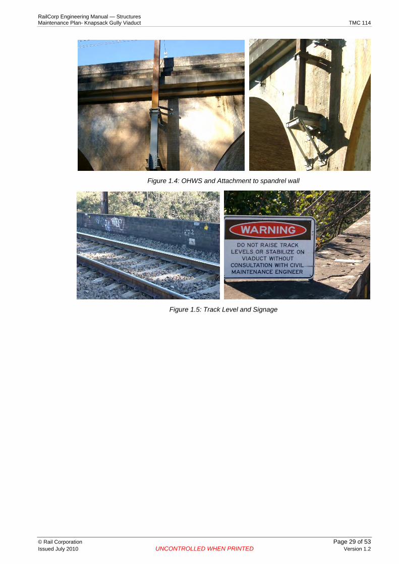
Figure 1.4: OHWS and Attachment to spandrel wall
Figure 1.5: Track Level and Signage
© Rail Corporation Page 29 of 53 Issued July 2010 UNCONTROLLED WHEN PRINTED Version 1.2

RailCorp Engineering Manual — Structures Maintenance Plan- Knapsack Gully Viaduct TMC 114
2. Defects
Figure 2.1: Longitudinal Crack on Upside Arch of Span 5
© Rail Corporation Page 30 of 53 Issued July 2010 UNCONTROLLED WHEN PRINTED Version 1.2

RailCorp Engineering Manual — Structures Maintenance Plan- Knapsack Gully Viaduct TMC 114
Figure 2.2: Crack on Spandrel Wall between spans No. 4 and 5
Figure 2.3: Sub standard Refuge
© Rail Corporation Page 31 of 53 Issued July 2010 UNCONTROLLED WHEN PRINTED Version 1.2

RailCorp Engineering Manual — Structures Maintenance Plan- Knapsack Gully Viaduct TMC 114
Appendix 5 Failure Mode Chart The following chart was prepared to represent possible sequences of events leading to a situation where satisfactory track support no longer exists.
A scenario leading to loss of track support is covered in Figure 1: Failure Mode.
Information shown in the diagram on risk of failure is not comprehensive. It may be possible that other failure modes exist.
Intervention levels shown in the TMP are based on sound engineering judgment and requirements of typical railway bridges. Except for the issue of sudden ground movements, the risk levels associated with Knapsack Gully Viaduct are similar to other RailCorp bridges.
The risk of a derailment on the viaduct shall be managed in accordance with RailCorp Standards and includes guardrails, lower track speed and installation of concrete sleeper.
© Rail Corporation Page 32 of 53 Issued July 2010 UNCONTROLLED WHEN PRINTED Version 1.2

RailCorp Engineering Manual — Structures Maintenance Plan- Knapsack Gully Viaduct TMC 114
Knapsack Gully Viaduct – Possible Failure Sequence
Lateral forces due to earth pressure
Loss of support at Pier base due to scour
Differential Ground movement
Centrifugal force due to Train LL
Failure of stress bar
Failure of spandrel on parapet
Failure of Arch
Failure of Pier
Failure of Abutment
Loss of adequate track support
Cause Effect
Ultimate Effect
Figure 1 – Failure Mode
© Rail Corporation Page 33 of 53 Issued July 2010 UNCONTROLLED WHEN PRINTED Version 1.2
RailCorp Engineering Manual — Structures Maintenance Plan- Knapsack Gully Viaduct TMC 114
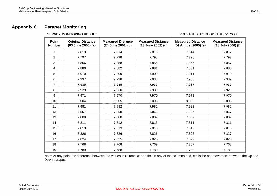
Appendix 6 Parapet Monitoring SURVEY MONITORING RESULT PREPARED BY: REGION SURVEYOR
Point Number
Original Distance (03 June 2000) (a)
Measured Distance (24 June 2001) (b)
Measured Distance (13 June 2002) (d)
Measured Distance (04 August 2005) (e)
Measured Distance (18 July 2006) (f)
1 7.813 7.814 7.813 7.814 7.812 2 7.797 7.798 7.798 7.798 7.797 3 7.856 7.858 7.856 7.857 7.857 4 7.880 7.882 7.881 7.881 7.880 5 7.910 7.909 7.909 7.911 7.910 6 7.937 7.938 7.938 7.938 7.939 7 7.935 7.935 7.935 7.937 7.937 8 7.929 7.930 7.930 7.932 7.929 9 7.971 7.970 7.970 7.971 7.970
10 8.004 8.005 8.005 8.006 8.005 11 7.981 7.982 7.982 7.982 7.982 12 7.857 7.858 7.858 7.857 7.857 13 7.808 7.808 7.809 7.809 7.809 14 7.811 7.812 7.813 7.811 7.811 15 7.813 7.813 7.813 7.816 7.815 16 7.826 7.826 7.826 7.826 7.827 17 7.824 7.825 7.825 7.827 7.826 18 7.768 7.768 7.769 7.767 7.768 19 7.789 7.788 7.789 7.789 7.789
Note: At any point the difference between the values in column ‘a’ and that in any of the columns b, d, etc is the net movement between the Up and Down parapets.
© Rail Corporation Page 34 of 53 Issued July 2010 UNCONTROLLED WHEN PRINTED Version 1.2

Parapet Survey Monitoring Results
8.~ .-------------------------------------------------------------------------------.
8.000 ________ ~ __ ___ __________ ' __ __ ___ ________ o __ __ _____________ ___ ____________ ___ ____________ ___ _ o ___________ ___ _ ~ ___________ __ ___ ________ _
-§. 7.950 Q) u
~ WO 7.900 i5
~ ... 7.850 ::I Cl)
7 .8(1) --------. -- --- --------- 11 · ---- ---------1t · --- ------------ --- ------------ --- ------------ --- -= ---------- --- -. ----------- -- ------------
7.750 00/1 2199 19/04/01 01109/02 14/01/04 2&1)5,{)5 10/10/06 22/02AJB
Date
-+-Point 1 --- Point 2 --.-- Point 3 --><- Point 4 --Point 5 -+- PointS -+- Point? - PointS - Point9 -o- Point 10 -a-Point 11 --.:rPoint 12 ~-Point 13 --Point 14 -+- Point 15 Point16 - Point17 - Point18 -+- Point 19
RailCorp Engineering Manual — Structures Maintenance Plan- Knapsack Gully Viaduct TMC 114
© Rail Corporation Page 35 of 53 Issued July 2010 UNCONTROLLED WHEN PRINTED Version 1.2
RailCorp Engineering Manual — Structures Maintenance Plan- Knapsack Gully Viaduct TMC 114
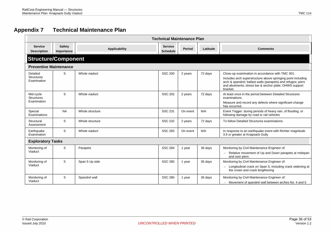
Appendix 7 Technical Maintenance Plan Technical Maintenance Plan
Service Description
Safety Importance
Applicability Service
Schedule Period Latitude Comments
Structure/Component Preventive Maintenance Detailed Structures Examination
S Whole viaduct SSC 200 2 years 72 days Close-up examination in accordance with TMC 301. Includes arch superstructure above springing point including arch & spandrel; ballast walls (parapets) and refuges; piers and abutments; stress bar & anchor plate; OHWS support bracket.
Mid-cycle Structures Examination
S Whole viaduct SSC 202 2 years 72 days At least once in the period between Detailed Structures examinations. Measure and record any defects where significant change has occurred.
Special Examinations
NA Whole structure SSC 231 On event N/A Event Trigger: during periods of heavy rain, of flooding, or following damage by road or rail vehicles
Structural Assessment
S Whole structure SSC 232 2 years 72 days To follow Detailed Structures examinations.
Earthquake Examination
S Whole viaduct SSC 283 On event N/A In response to an earthquake event with Richter magnitude 3.5 or greater at Knapsack Gully
Exploratory Tasks Monitoring of Viaduct
S Parapets SSC 284 1 year 36 days Monitoring by Civil Maintenance Engineer of: − Relative movement of Up and Down parapets at midspan
and over piers Monitoring of Viaduct
S Span 5 Up side SSC 285 1 year 36 days Monitoring by Civil Maintenance Engineer of: − Longitudinal crack on Span 5, including crack widening at
the crown and crack lengthening
Monitoring of Viaduct
S Spandrel wall SSC 286 1 year 36 days Monitoring by Civil Maintenance Engineer of: − Movement of spandrel wall between arches No. 4 and 5
© Rail Corporation Page 36 of 53 Issued July 2010 UNCONTROLLED WHEN PRINTED Version 1.2

RailCorp Engineering Manual — Structures Maintenance Plan- Knapsack Gully Viaduct TMC 114
Technical Maintenance Plan
Service Description
Safety Importance
Applicability Service
Schedule Period Latitude Comments
Corrective Maintenance Routine NA Deck drainage systems TMC 302 On Event N/A Clear deck drainage systems. Maintenance Brickwork
Ballast Signage Bridge ends
Repoint joints in brickwork where severe mortar loss has occurred; seal cracks in brickwork; remove plant growth from brickwork. Monitor ballast depth to avoid gradual build-up of excessive ballast. Ensure warning signs re track level are visible. Remove local track depressions at abutments to reduce impact effects on viaduct.
Steelwork Maintenance
NA Steel members: − OHWS and support brackets − Exposed stress bar and anchor plate
TMC 302 On Event N/A Maintenance to be carried out within 2 years of the publication of this maintenance Plan.
Other Work Risk analysis NA Guard rails N/A On Event N/A Perform risk analysis on the need to install guardrails for both
tracks Complete by December 2009
Upgrade NA Access road N/A On Event N/A Upgrade access road leading to Span 5 to allow vehicle access road mounted boom lifts to be used. leading to Span 5 to allow vehicle
Complete design by June 2009 Installation by June 2010
mounted boom lifts to be used
Design of NA Span 5 arch N/A On Event N/A Close visual examination of the Upside of Span 5 arch to remedial work design remedial work
Examination by June 2010 Remedial work by June 2011
Monitoring NA N/A On Event N/A Research, develop, trial and commission a monitoring system for the system for the stress bar stress bar Development by Dec 2010
Trial by Dec 2011 Commission by June 2012
Load rating NA Track maintenance machines N/A On Event N/A Perform a load rating for track maintenance machines Complete by Dec 2008
© Rail Corporation Page 37 of 53 Issued July 2010 UNCONTROLLED WHEN PRINTED Version 1.2

RailCorp Engineering Manual — Structures Maintenance Plan- Knapsack Gully Viaduct TMC 114
Technical Maintenance Plan
Service Description
Safety Importance
Applicability Service
Schedule Period Latitude Comments
Increase wall height
NA Refuges N/A On Event N/A Increase height of parapet wall at refuges on the Up side. Design by June 2009 Installation by June 2010
Install new refuges
NA Refuges N/A On Event N/A Investigate installation of new refuges at alternate piers and staggered to those on the Up Side. Design by June 2010. Design to consider implications of minimum warning time requirements. Installation, if required, by June 2011
Removable weather protection cap
NA Stress bar Anchor plate
N/A On Event N/A Removable weather protection cap to the stress bar and anchor plate on the Down Side Design by June 2009 Installation by June 2010
© Rail Corporation Page 38 of 53 Issued July 2010 UNCONTROLLED WHEN PRINTED Version 1.2

RailCorp Engineering Manual — Structures Maintenance Plan- Knapsack Gully Viaduct TMC 114
Appendix 8 Service Schedules
SSC 283 Earthquake Examination of Knapsack Gully Viaduct Service Schedule No. SSC 283 Page 1 of 1
Description Ellipse Standard Job
Examination of Knapsack Gully Viaduct following nominated earthquake event
Personnel Accredited to examine structures and identify structural defects
Equipment Nil
Reference TMC 301 Structures Examination; TMC 114 Maintenance Plan Knapsack Gully Viaduct
Task
Start The Job
1 Examine structure visually for general condition and for evidence of earthquake damage
2 Examine FOOTINGS. Pay particular attention to damage
3 Examine ABUTMENTS. Pay particular attention to cracking, movement/misalignment of abutment walls, condition of masonry
4 Examine PIERS. Pay particular attention to cracking, movement/misalignment of abutment walls, condition of masonry
5 Examine ARCHES. Pay particular attention to cracking, displacement or deflection of spandrel walls, loose masonry, condition of tie-rods and other fastenings
6 Examine ANCILLARY equipment. Pay particular attention to the serviceability of personnel refuges, parapets, OHWS supports
7 Examine approach track visually for formation failure, settlement or unevenness
8 Examine signs for condition and effectiveness
9 Identify and record all defects
10 Protect site (if required) pending further corrective actions
11 Repair defects (where time and resources are available) or report/arrange corrective action
Finish The Job
12 Compile weekly summary of exceedents
13 Update defect listing and examination report
14 Complete examination certification
© Rail Corporation Page 39 of 53 Issued July 2010 UNCONTROLLED WHEN PRINTED Version 1.2
RailCorp Engineering Manual — Structures Maintenance Plan- Knapsack Gully Viaduct TMC 114
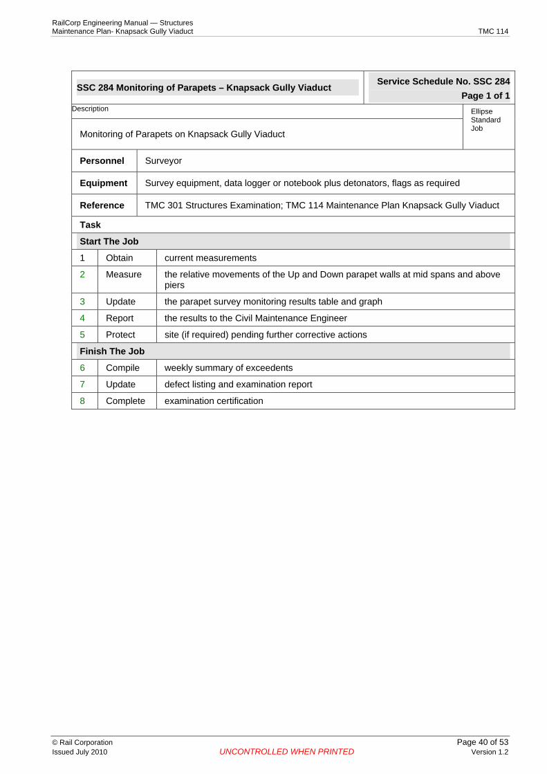
SSC 284 Monitoring of Parapets – Knapsack Gully Viaduct Service Schedule No. SSC 284 Page 1 of 1
Description Ellipse Standard Job
Monitoring of Parapets on Knapsack Gully Viaduct
Personnel Surveyor
Equipment Survey equipment, data logger or notebook plus detonators, flags as required
Reference TMC 301 Structures Examination; TMC 114 Maintenance Plan Knapsack Gully Viaduct
Task
Start The Job
1 Obtain current measurements
2 Measure the relative movements of the Up and Down parapet walls at mid spans and above piers
3 Update the parapet survey monitoring results table and graph
4 Report the results to the Civil Maintenance Engineer
5 Protect site (if required) pending further corrective actions
Finish The Job
6 Compile weekly summary of exceedents
7 Update defect listing and examination report
8 Complete examination certification
© Rail Corporation Page 40 of 53 Issued July 2010 UNCONTROLLED WHEN PRINTED Version 1.2

RailCorp Engineering Manual — Structures Maintenance Plan- Knapsack Gully Viaduct TMC 114
SSC 285 Monitoring of Span 5 – Knapsack Gully Viaduct Service Schedule No. SSC 285 Page 1 of 1
Description Ellipse Standard Job
Monitoring of longitudinal crack on Up side of Span 5 Knapsack Gully Viaduct
Personnel Accredited to examine bridges and identify bridge defects
Equipment Access equipment, binoculars, measuring tape, crayon, data logger or notebook plus detonators, flags as required
Reference TMC 301 Structures Examination; TMC 114 Maintenance Plan Knapsack Gully Viaduct
Task
Start The Job
1 Obtain current measurements, examination report and layout sketch
2 Monitor the width of the existing crack on the Up side of Span 5 by viewing the scaled bar
3 Measure and record the longitudinal extent of the existing crack (with associated crack widths at 15-20 locations)
4 Map the crack length and widths on a plan of Span 5
5 Report any significant changes to the Civil Maintenance Engineer
6 Protect site (if required) pending further corrective actions
Finish The Job
7 Compile weekly summary of exceedents
8 Update defect listing and examination report
9 Complete examination certification
© Rail Corporation Page 41 of 53 Issued July 2010 UNCONTROLLED WHEN PRINTED Version 1.2

RailCorp Engineering Manual — Structures Maintenance Plan- Knapsack Gully Viaduct TMC 114
SSC 286 Monitoring of Spandrel Wall – Knapsack Gully Viaduct Service Schedule No. SSC 286 Page 1 of 1
Description Ellipse Standard Job
Monitoring of cracked spandrel wall between arches 4 and 5 Knapsack Gully Viaduct
Personnel Accredited to examine bridges and identify bridge defects
Equipment Access equipment, measuring tape, crayon, data logger or notebook plus detonators, flags as required
Reference TMC 301 Structures Examination; TMC 114 Maintenance Plan Knapsack Gully Viaduct
Task
Start The Job
1 Obtain current measurements, examination report and layout sketch
2 Measure and record the extent, profile and outward movement of the existing crack in the spandrel wall between arches 4 and 5
3 Map the essential features of the crack on a sketch
4 Report any significant changes to the Civil Maintenance Engineer
5 Protect site (if required) pending further corrective actions
Finish The Job
6 Compile weekly summary of exceedents
7 Update defect listing and examination report
8 Complete examination certification
© Rail Corporation Page 42 of 53 Issued July 2010 UNCONTROLLED WHEN PRINTED Version 1.2

RailCorp Engineering Manual — Structures Maintenance Plan- Knapsack Gully Viaduct TMC 114
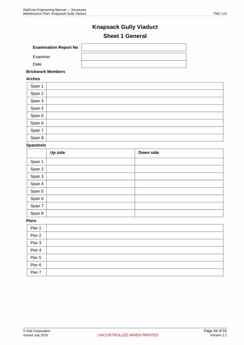
Appendix 9 Examination Reports Examination Reports The format adopted for the Stanwell Park Viaduct is to be used for reporting shown in this Appendix. The Bridge Examiner shall use this reporting format for all future inspection cycles.
Sheets 1 to 10 with the recorded information shall be forwarded to the Chief Engineer, Civil at the end of each detailed inspection. The TMP will be updated to include this information.
© Rail Corporation Page 43 of 53 Issued July 2010 UNCONTROLLED WHEN PRINTED Version 1.2
RailCorp Engineering Manual — Structures Maintenance Plan- Knapsack Gully Viaduct TMC 114
Knapsack Gully Viaduct Sheet 1 General
Examination Report No
Examiner
Date
Brickwork Members
Arches
Span 1
Span 2
Span 3
Span 4
Span 5
Span 6
Span 7
Span 8
Spandrels
Up side Down side
Span 1
Span 2
Span 3
Span 4
Span 5
Span 6
Span 7
Span 8
Piers
Pier 1
Pier 2
Pier 3
Pier 4
Pier 5
Pier 6
Pier 7
© Rail Corporation Page 44 of 53 Issued July 2010 UNCONTROLLED WHEN PRINTED Version 1.2

RailCorp Engineering Manual — Structures Maintenance Plan- Knapsack Gully Viaduct TMC 114
Knapsack Gully Viaduct Sheet 2 General
Examination Report No
Examiner
Date
Abutments
Abut 1
Abut 2
Wingwalls
No 1
No 2
No 3
No 4
Parapets
Up side Down side
Span 1
Span 2
Span 3
Span 4
Span 5
Span 6
Span 7
Span 8
Refuges
Up side Down side
Span 1
Span 2
Span 3
Span 4
Span 5
Span 6
Span 7
Span 8
© Rail Corporation Page 45 of 53 Issued July 2010 UNCONTROLLED WHEN PRINTED Version 1.2

RailCorp Engineering Manual — Structures Maintenance Plan- Knapsack Gully Viaduct TMC 114
Knapsack Gully Viaduct Sheet 3 General
Examination Report No
Examiner
Date
Stress Bar, Anchorages
Bar Number Condition/ Description
Span 1
Span 2
Span 3
Span 4
Span 5
Span 6
Span 7
Span 8
OHW Structures
Upside Connection Downside Connection Steel Gantry Connections
Pier 1
Pier 3
Pier 5
Pier 7
© Rail Corporation Page 46 of 53 Issued July 2010 UNCONTROLLED WHEN PRINTED Version 1.2

RailCorp Engineering Manual — Structures Maintenance Plan- Knapsack Gully Viaduct TMC 114
Knapsack Gully Viaduct Sheet 4 General
Examination Report No
Examiner
Date
Concrete/CRC Protection Cover and Cap to anchorages
Upside
Downside
Deck
Drainage
Ballast Depth
Guardrails
Track at Bridge ends
Water proof deck membrane
© Rail Corporation Page 47 of 53 Issued July 2010 UNCONTROLLED WHEN PRINTED Version 1.2

RailCorp Engineering Manual — Structures Maintenance Plan- Knapsack Gully Viaduct TMC 114
Knapsack Gully Viaduct Sheet 5 General
Examination Report No
Examiner
Date
General
Comments – CME, Structures Manager, BE
© Rail Corporation Page 48 of 53 Issued July 2010 UNCONTROLLED WHEN PRINTED Version 1.2

RailCorp Engineering Manual — Structures Maintenance Plan- Knapsack Gully Viaduct TMC 114
Knapsack Gully Viaduct Sheet 6 – Parapet Defect Details
Examination Report No
Examiner
Date
Defect Dimensions
Defect No1 Length ‘Ave’
Width Offset2 Photo No Change3 Comment4
NOTES 1 Prepare sketch to show defect locations. Mark size and location of defects 2 Record misalignment of adjacent surfaces at a crack 3 Indicate � = change; � = no change 4 Include comment where change has occurred. Compare with Defect Intervention Level
© Rail Corporation Page 49 of 53 Issued July 2010 UNCONTROLLED WHEN PRINTED Version 1.2

RailCorp Engineering Manual — Structures Maintenance Plan- Knapsack Gully Viaduct TMC 114
Knapsack Gully Viaduct Sheet 7 – Spandrel Defect Details
Examination Report No
Examiner
Date
Defect Dimensions
Defect No1 Length ‘Ave’
Width Offset2 Photo No Change3 Comment4
NOTES 1 Prepare sketch to show defect locations. Mark size and location of defects 2 Record misalignment of adjacent surfaces at a crack 3 Indicate � = change; � = no change 4 Include comment where change has occurred. Compare with Defect Intervention Level
© Rail Corporation Page 50 of 53 Issued July 2010 UNCONTROLLED WHEN PRINTED Version 1.2

RailCorp Engineering Manual — Structures Maintenance Plan- Knapsack Gully Viaduct TMC 114
Knapsack Gully Viaduct Sheet 8 – Arch Defect Details
Examination Report No
Examiner
Date
Defect Dimensions
Defect No1 Length ‘Ave’
Width Offset2 Photo No
Change 3 Comment4
NOTES 1 Prepare sketch to show defect locations. Mark size and location of defects 2 Record misalignment of adjacent surfaces at a crack 3 Indicate � = change; � = no change 4 Include comment where change has occurred. Compare with Defect Intervention Level
© Rail Corporation Page 51 of 53 Issued July 2010 UNCONTROLLED WHEN PRINTED Version 1.2

RailCorp Engineering Manual — Structures Maintenance Plan- Knapsack Gully Viaduct TMC 114
Knapsack Gully Viaduct Sheet 9 – Abutment Defect Details
Examination Report No
Examiner
Date
Defect Dimensions
Defect No1 Length ‘Ave’
Width Offset2 Photo No Change3 Comment4
NOTES 1 Prepare sketch to show defect locations. Mark size and location of defects 2 Record misalignment of adjacent surfaces at a crack 3 Indicate � = change; � = no change 4 Include comment where change has occurred. Compare with Defect Intervention Level
© Rail Corporation Page 52 of 53 Issued July 2010 UNCONTROLLED WHEN PRINTED Version 1.2

RailCorp Engineering Manual — Structures Maintenance Plan- Knapsack Gully Viaduct TMC 114
Knapsack Gully Viaduct Sheet 10 – Pier Defect Details
Examination Report No
Examiner
Date
Defect Dimensions
Defect No1 Length ‘Ave’
Width Offset2 Photo No Change3 Comment4
NOTES 1 Prepare sketch to show defect locations. Mark size and location of defects 2 Record misalignment of adjacent surfaces at a crack 3 Indicate � = change; � = no change 4 Include comment where change has occurred. Compare with Defect Intervention Level
© Rail Corporation Page 53 of 53 Issued July 2010 UNCONTROLLED WHEN PRINTED Version 1.2