tm femur antegrade gt/pf nailing systemaz621074.vo.msecnd.net/syk-mobile-content-cdn/... · pf...
TRANSCRIPT
T2 AlphaTM Femur Antegrade GT/PF
Nailing System
Operative technique

2
ContentsIndications, contraindications and intended use .................................................. 3
MRI Safety Information ....................................... 4
Additional information......................................... 5
Locking options .................................................... 7
Operative technique ............................................11
Pre-operative planning .................................11
Patient positioning and fracture reduction ....11
Incision ......................................................... 12
Entry point ................................................... 13
Opening ........................................................ 14
Guide wire insertion & reaming ................. 16
Reaming ........................................................17
Nail selection ................................................ 18
Nail insertion ............................................... 19
Recon locking mode ..................................... 23
Antegrade proximal locking mode .............. 29
Internal apposition / compression mode ..... 34
External compression mode ........................ 36
Guided distal locking ................................... 37
Freehand distal locking ............................... 46
Advanced locking screws ............................ 48
Set screw and end cap insertion .................. 51
Nail removal ................................................. 52
This publication sets forth detailed recommended procedures for using Stryker devices and instruments. It offers guidance that you should heed, but, as with any such technical guide, each surgeon must consider the particular needs of each patient and make appropriate adjustments when and as required. A workshop training is recommended prior to performing your first surgery. All non-sterile devices must be cleaned and sterilized before use.
Follow the instructions provided in our cleaning and sterilization guide (OT-RG-1). Multi-component instruments must be disassembled for cleaning. Please refer to the corresponding assembly/disassembly instructions.
Please remember that the compatibility* of different product systems has not been tested unless specified otherwise in the product labeling.
See package insert (Instructions for Use) (L22000034, L22000035, L22000045, L22000007) for a complete list of potential adverse effects, contraindications, warnings and precautions. The surgeon must discuss all relevant risks including the finite lifetime of the device with the patient when necessary.
Use instruments/implants as described inthis operative technique to avoid damageto instruments/implants or bone and softtissue.
T2 AlphaFemur Antegrade GT/PF Nailing System
* The terms 'all Stryker IM Nailing Systems' / 'all titanium-madeStryker IM Nailing Systems' (described in IFU L22000035 andL22000045) are defined as T2 Alpha Femur Antegrade GT/PF NailingSystem and T2 Alpha Tibia Nailing System.
3
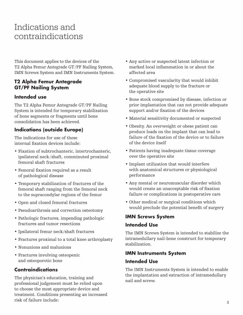
This document applies to the devices of the T2 Alpha Femur Antegrade GT / PF Nailing System, IMN Screws System and IMN Instruments System.
T2 Alpha Femur Antegrade GT/PF Nailing System
Intended use
The T2 Alpha Femur Antegrade GT / PF Nailing System is intended for temporary stabilization of bone segments or fragments until bone consolidation has been achieved.
Indications (outside Europe)
The indications for use of these internal fixation devices include:
• Fixation of subtrochanteric, intertrochanteric,ipsilateral neck / shaft, comminuted proximalfemoral shaft fractures
• Femoral fixation required as a resultof pathological disease
• Temporary stabilization of fractures of thefemoral shaft ranging from the femoral neckto the supracondylar regions of the femur
• Open and closed femoral fractures
• Pseudoarthrosis and correction osteotomy
• Pathologic fractures, impending pathologicfractures and tumor resections
• Ipsilateral femur neck/shaft fractures
• Fractures proximal to a total knee arthroplasty
• Nonunions and malunions
• Fractures involving osteopenicand osteoporotic bone
Contraindications
The physician’s education, training and professional judgement must be relied upon to choose the most appropriate device and treatment. Conditions presenting an increased risk of failure include:
• Any active or suspected latent infection ormarked local inflammation in or about theaffected area
• Compromised vascularity that would inhibitadequate blood supply to the fracture orthe operative site
• Bone stock compromised by disease, infection orprior implantation that can not provide adequatesupport and/or fixation of the devices
• Material sensitivity documented or suspected
• Obesity. An overweight or obese patient canproduce loads on the implant that can lead tofailure of the fixation of the device or to failureof the device itself
• Patients having inadequate tissue coverageover the operative site
• Implant utilization that would interferewith anatomical structures or physiologicalperformance
• Any mental or neuromuscular disorder whichwould create an unacceptable risk of fixationfailure or complications in postoperative care
• Other medical or surgical conditions whichwould preclude the potential benefit of surgery
IMN Screws System
Intended Use
The IMN Screws System is intended to stabilize the intramedullary nail-bone construct for temporary stabilization.
IMN Instruments System
Intended Use
The IMN Instruments System is intended to enable the implantation and extraction of intramedullary nail and screw.
Indications and contraindications

4
The MRI safety information provided is based on testing which did not include supplementary devices. If there are supplementary devices (i.e. plates, screws, wires, etc.) present in proximity to the T2 Alpha Femur Antegrade GT/PF Nailing System and IMN Screws System, this could result in additional MRI effects and the information provided above may not apply.
Non-clinical testing has demonstrated that the T2 Alpha Femur Antegrade GT/PF Nailing System and IMN Screws System are MR Conditional. A patient with this device can be safely scanned in an MR system meeting the following conditions:
• Static magnetic field of 1.5T or 3.0T
• Maximum spatial field gradientof 3,000 gauss/cm (30 T/m)
• Maximum MR system reported, wholebody averaged specific absorption rate(SAR) of 2 W/kg (Normal Operating Mode)
Under the scan conditions defined above, the T2 Alpha Femur Antegrade GT/PF Nailing System and IMN Screws System are expected to produce a maximum temperature rise of less than 6.9°C after 15 minutes of continuous scanning.
In non-clinical testing, the image artifact caused by the device extends approximately 27mm from the T2 Alpha Femur Antegrade GT/PF Nailing System and IMN Screws System when imaged with a spin echo or gradient echo pulse sequence and a 3.0 T MRI system.
MRI Safety Information

5
T2 Alpha Femur Antegrade GT/PF Nailing System
T2 Alpha Femur Antegrade GT / PF Nailing System includes two options for antegrade femoral nailing: The Femoral Nail GT for greater trochanteric entry and the Femoral Nail PF for piriformis fossa entry.
Nail diameter
Ø9mm – Ø15mm*
Nail length
240mm – 480mm in 20mm increments
Compression Screw Femur
Femoral Nail GTFemoral Nail PF
Additional Information
Set Screw GT / PF
End Cap Lower Extremity** and End Caps GT / PF
+5mm(Ø13mm)
+10mm(Ø13mm)
+15mm(Ø13mm)
+20mm(Ø13mm)
+0mm(Ø8mm)
IMN Screws
Locking Screw
Ø5mm, 25mm – 120mm length 25mm - 60mm in 2.5mm increments 60mm - 120mm in 5mm increments
Advanced Locking Screws
Ø5mm, 30mm – 100mm length 30mm - 60mm in 2.5mm increments 60mm - 100mm in 5mm increments
T2 Lag Screws Recon***
Ø6.5mm, 65mm – 130mm length
*Check with local representative regarding availability of implant sizes**T2 Alpha Tibia Nailing System***Existing screws of T2 Recon Nailing SystemScrew length measures from top of head to tip
6
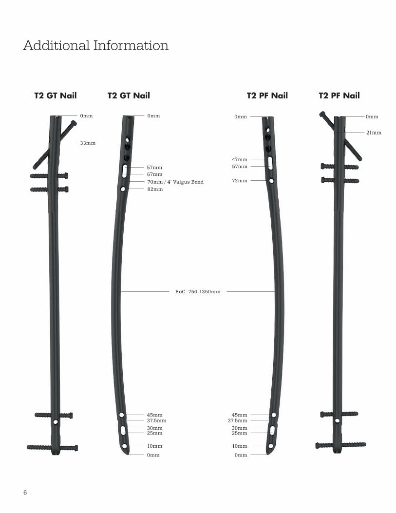
Additional Information
45mm37.5mm30mm25mm
10mm
0mm
T2 GT Nail
0mm0mm
33mm
70mm / 4º Valgus Bend
57mm67mm
82mm
T2 GT Nail T2 PF Nail
0mm 0mm
21mm
45mm37.5mm
30mm25mm
10mm
0mm
47mm57mm
72mm
RoC: 750-1350mm
T2 PF Nail
7
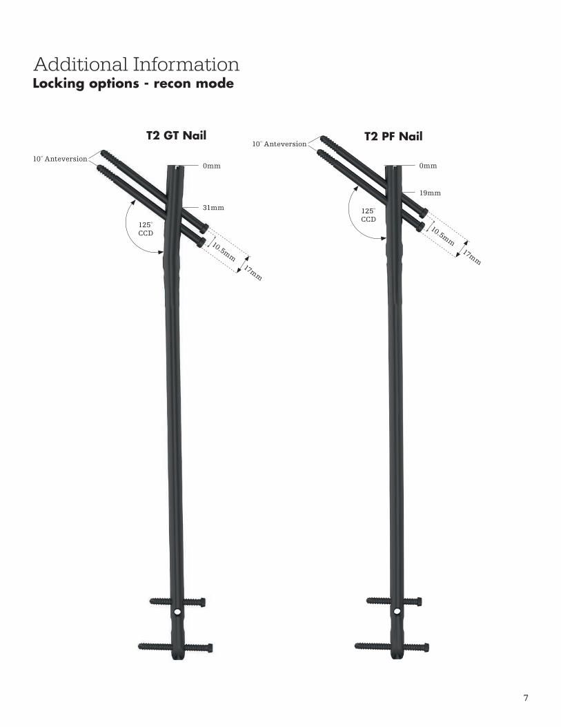
125º CCD
125º CCD
10º Anteversion
10º Anteversion
0mm
31mm
0mm
19mm
T2 GT Nail T2 PF Nail
Additional InformationLocking options - recon mode
10.5mm17mm
10.5mm17mm
8
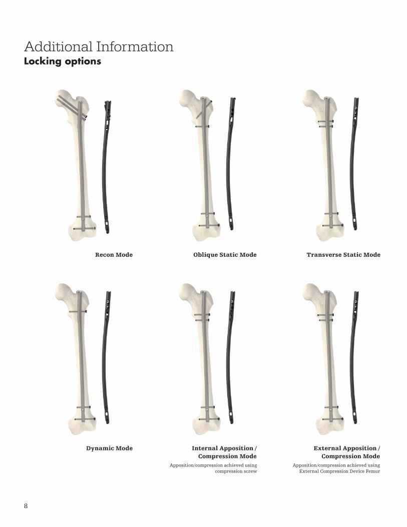
Recon Mode
Dynamic Mode
Oblique Static Mode
Internal Apposition / Compression Mode
Transverse Static Mode
External Apposition / Compression Mode
Apposition/compression achieved using External Compression Device Femur
Apposition/compression achieved using compression screw
Additional InformationLocking options
9
Additional InformationPackaging
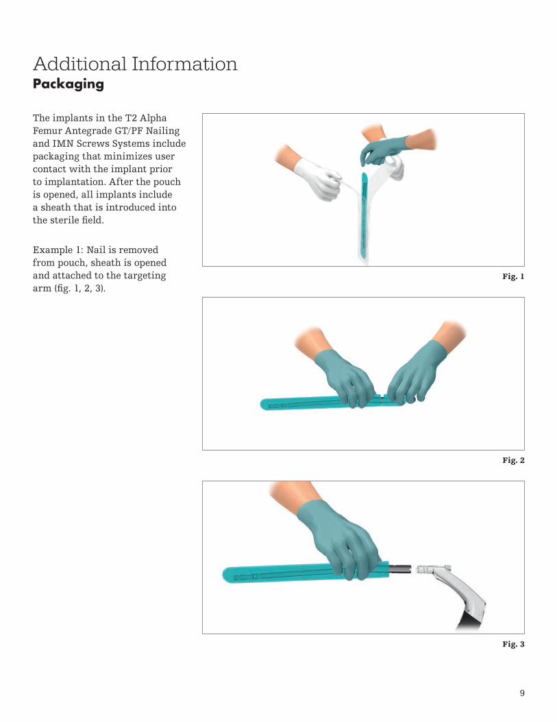
The implants in the T2 Alpha Femur Antegrade GT/PF Nailing and IMN Screws Systems include packaging that minimizes user contact with the implant prior to implantation. After the pouch is opened, all implants include a sheath that is introduced into the sterile field.
Example 1: Nail is removed from pouch, sheath is opened and attached to the targeting arm (fig. 1, 2, 3).
Fig. 1
Fig. 2
Fig. 3
10
Additional InformationPackaging
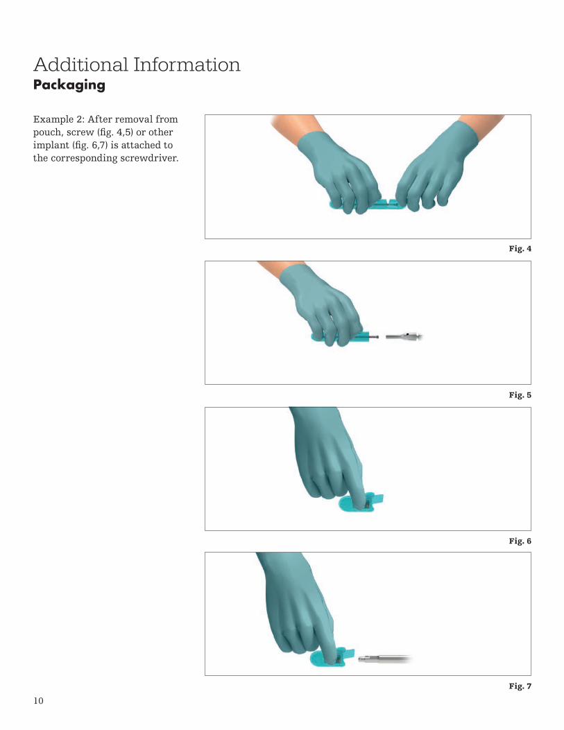
Example 2: After removal from pouch, screw (fig. 4,5) or other implant (fig. 6,7) is attached to the corresponding screwdriver.
Fig. 4
Fig. 5
Fig. 6
Fig. 7

11
Thorough evaluation of pre-operative radiographs of the affected extremity is critical. Careful radiographic examination of the trochanteric region and intercondylar regions may prevent certain intra-operative complications.
The proper nail length when using the Femoral Nail GT should extend from the tip of the greater trochanter to the distal epiphyseal scar. The proper nail length when using the Femoral Nail PF should extend from the piriformis fossa to the distal epiphyseal scar.
Operative techniquePre-operative planning
Patient positioning and reduction
The T2 Alpha Femur Antegrade GT Nailing System and the T2 Alpha Femur Antegrade PF Nailing System offer two options for antegrade femoral nailing. The design of the Femoral Nail GT allows for insertion through the tip of the greater trochanter and the Femoral Nail PF allows for insertion through the piriformis fossa.
Patient positioning for the T2 Alpha femoral nail insertion is surgeon dependent. It is recommended to position the patient in the supine position on a fracture table (fig.8) or in a lateral position on a radiolucent table. Anatomic reduction of the fracture should be performed prior to reaming and nail insertion.
Fig. 8

12
Incision – Greater Trochanteric Entry – Femoral Nail GT
The tip of the greater trochanter can be located by palpation. Then, a longitudinal skin incision is made 2cm above the greater trochanter extending 3cm towards the iliac crest (fig. 9). Be prepared to lengthen the incision as needed.
The greater trochanter can also be located using X-ray.
Incision – Piriformis Fossa Entry – Femoral Nail PF
A skin incision is made beginning at the level of the greater trochanter extending proximal and slightly posterior, in line with the gluteus muscle, exposing the piriformis fossa for nail insertion.
Operative techniqueApproach
Fig. 9
13
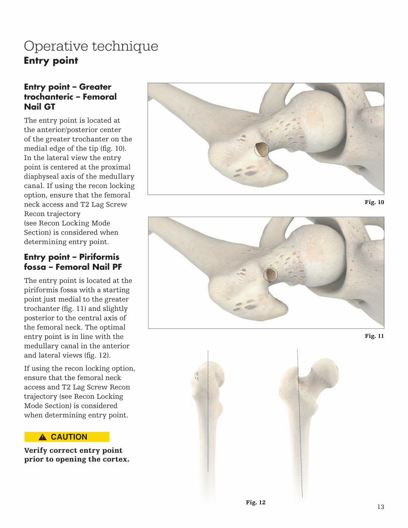
Entry point – Greater trochanteric – Femoral Nail GT
The entry point is located at the anterior/posterior center of the greater trochanter on the medial edge of the tip (fig. 10). In the lateral view the entry point is centered at the proximal diaphyseal axis of the medullary canal. If using the recon locking option, ensure that the femoral neck access and T2 Lag Screw Recon trajectory (see Recon Locking Mode Section) is considered when determining entry point.
Entry point – Piriformis fossa – Femoral Nail PF
The entry point is located at the piriformis fossa with a starting point just medial to the greater trochanter (fig. 11) and slightly posterior to the central axis of the femoral neck. The optimal entry point is in line with the medullary canal in the anterior and lateral views (fig. 12).
If using the recon locking option, ensure that the femoral neck access and T2 Lag Screw Recon trajectory (see Recon Locking Mode Section) is considered when determining entry point.
Operative techniqueEntry point
Verify correct entry point prior to opening the cortex.
Fig. 10
Fig. 11
Fig. 12
14
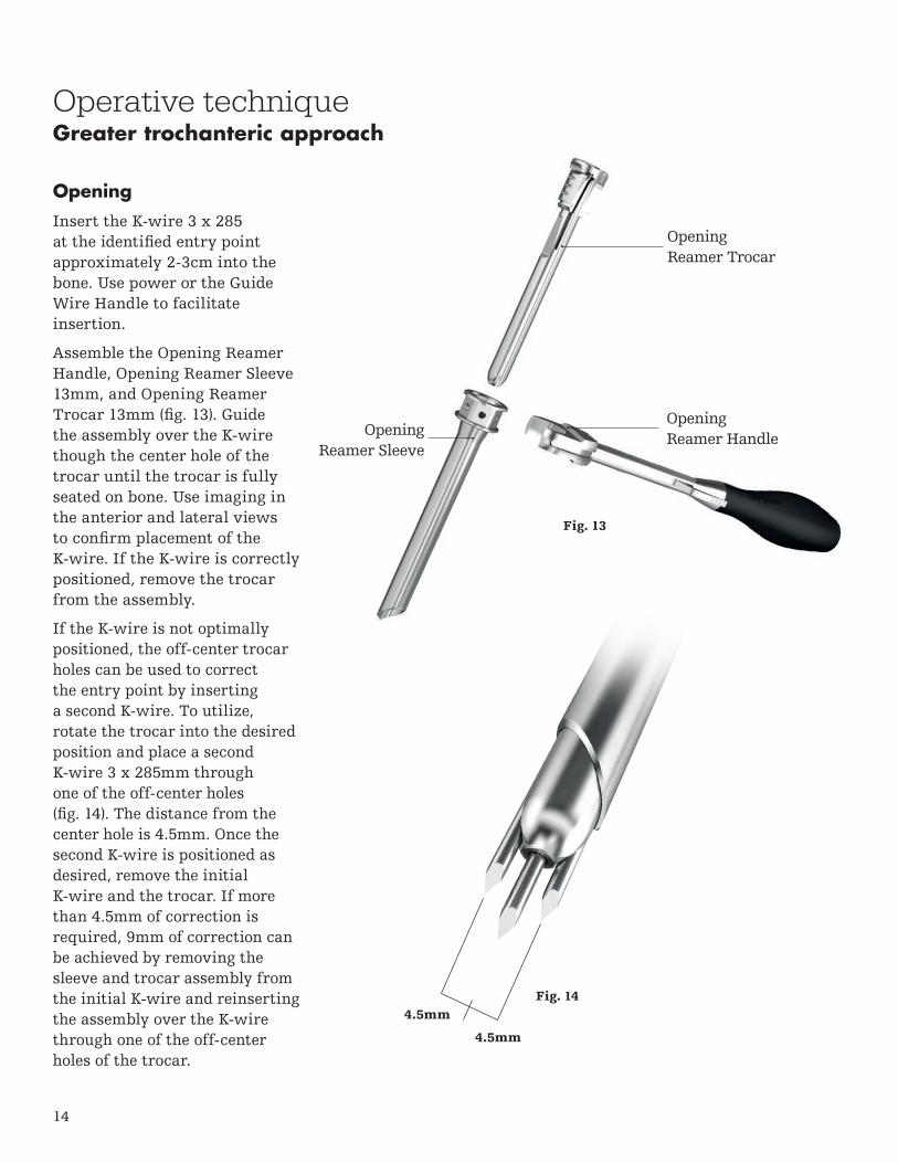
Opening
Insert the K-wire 3 x 285 at the identified entry point approximately 2-3cm into the bone. Use power or the Guide Wire Handle to facilitate insertion.
Assemble the Opening Reamer Handle, Opening Reamer Sleeve 13mm, and Opening Reamer Trocar 13mm (fig. 13). Guide the assembly over the K-wire though the center hole of the trocar until the trocar is fully seated on bone. Use imaging in the anterior and lateral views to confirm placement of the K-wire. If the K-wire is correctly positioned, remove the trocar from the assembly.
If the K-wire is not optimally positioned, the off-center trocar holes can be used to correct the entry point by inserting a second K-wire. To utilize, rotate the trocar into the desired position and place a second K-wire 3 x 285mm through one of the off-center holes (fig. 14). The distance from the center hole is 4.5mm. Once the second K-wire is positioned as desired, remove the initial K-wire and the trocar. If more than 4.5mm of correction is required, 9mm of correction can be achieved by removing the sleeve and trocar assembly from the initial K-wire and reinserting the assembly over the K-wire through one of the off-center holes of the trocar.
Fig. 14
Operative techniqueGreater trochanteric approach
Opening Reamer Trocar
Opening Reamer Sleeve
Opening Reamer Handle
4.5mm
4.5mm
Fig. 13
15
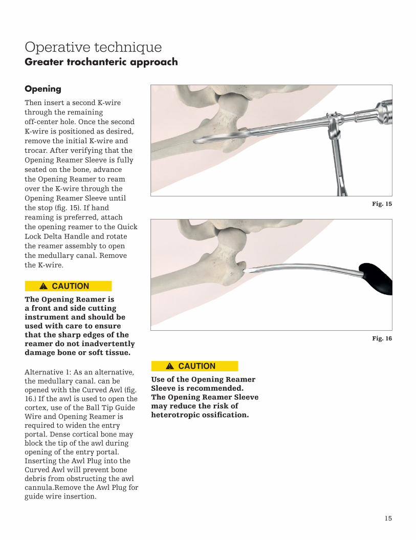
Opening
Then insert a second K-wire through the remaining off-center hole. Once the second K-wire is positioned as desired, remove the initial K-wire and trocar. After verifying that the Opening Reamer Sleeve is fully seated on the bone, advance the Opening Reamer to ream over the K-wire through the Opening Reamer Sleeve until the stop (fig. 15). If hand reaming is preferred, attach the opening reamer to the Quick Lock Delta Handle and rotate the reamer assembly to open the medullary canal. Remove the K-wire.
Operative techniqueGreater trochanteric approach
The Opening Reamer is a front and side cutting instrument and should be used with care to ensure that the sharp edges of the reamer do not inadvertently damage bone or soft tissue.
Use of the Opening ReamerSleeve is recommended. The Opening Reamer Sleeve may reduce the risk of heterotropic ossification.
Alternative 1: As an alternative, the medullary canal. can be opened with the Curved Awl (fig. 16.) If the awl is used to open the cortex, use of the Ball Tip Guide Wire and Opening Reamer is required to widen the entry portal. Dense cortical bone may block the tip of the awl during opening of the entry portal. Inserting the Awl Plug into the Curved Awl will prevent bone debris from obstructing the awl cannula.Remove the Awl Plug for guide wire insertion.
Fig. 15
Fig. 16

16
Operative technique
Do not use bent guide wires.
Guide wire insertion
Insert the Ball Tip Guide Wire 3 x 1000mm through the Guide Wire Handle (fig. 17). Adjust the handle as desired and lock the assembly by closing the fixation lever. Advance the Ball Tip Guide Wire through the fracture site to the level of the distal epiphyseal scar or the mid pole of the patella. Verify position of the guide wire tip in the anterior and lateral views.
The Guide Wire Handle can accommodate guide wires and K-wires with diameters from 1.8mm – 4mm. If necessary, loosen or tighten the adjustment wheel to increase or decrease the diameter of the insertion hole.
The Reduction Rod and Quick Lock Delta Handle assembly may be used as a fracture reduction tool to facilitate guide wire insertion through the fracture site (fig. 18).
Confirm correct position of guide wire prior to reaming.
Guide wire insertion
Release lever
Fixation lever
Adjustment wheel
Fig. 17
Fig. 18

17
Operative technique
Care must be taken to ensure that the entry portal is not extended laterally during reaming. This could lead to resection of more bone at the entry site, which in turn would lead to an offset position for the nail and a risk of shaft fracture.
Excessive heat generation during reaming / drilling can cause soft tissue or bone damage.
Reaming
Once the guide wire is positioned as desired, remove the Guide Wire Hand and, if a reamed technique is used, commence reaming in 0.5mm increments (fig. 19) until the desired diameter is achieved. The ball tip at the end of the guide wire will stop the reamer head.
To help maintain the position of the guide wire during reamer shaft extraction, press the funnel tip end of the Guide Wire Pusher (fig. 20) to the end of the power tool while extracting the reamer from the medullary canal.
Alternatively, the T2 Alpha Femoral Nail may be inserted without reaming of the subtrochanteric and diaphyseal region of the femur, particularly in elderly patients with wide medullary canals. If appropriate, after opening of the canal has been performed using the opening reamer, the nail can be inserted without further reaming of the medullary canal.
Fig. 19
Fig. 20

18
End of Guide Wire Ruleris the measurement reference Fig. 22
Operative technique
Ensure by fluoroscopy that curvature, length and diameter of selected nail fit the patient's anatomy.
Diameter
The diameter of the selected T2 Alpha Femoral Nail should be 1 - 1.5mm smaller than that of the last reamer used. The diameter may be determined by using the X-ray ruler at the smallest diameter of the medullary canal at the femoral isthmus under fluoroscopy (fig. 21).
Length
Determine appropriate nail length by measuring the remaining length of the Ball Tip Guide Wire. Place the Guide Wire Ruler (fig. 22) on the Ball Tip Guide Wire and read the correct nail length at the end of the Ball Tip Guide Wire on the Guide Wire Ruler. Ensure that the tip of the Guide Wire Ruler is fully seated on the bone prior to determining measurement. If the Ball Tip Guide Wire is between two length markings, use of the shorter nail is recommended.
The diameter of the selected T2 Alpha Femoral Nail must be at least 1mm – 1.5mm smaller than the last reamer used.
Do not touch sharp edges of drill bits, reamer heads, and cutting tools with surgical gloves. Take care when handling sharp edges of packaging and instruments.
Image indicates an estimated canal diameter/width of 9mm.
Fig. 21
Nail selection

19
Operative technique
To assemble the Targeting Arm Femur GT or Targeting Arm Femur PF, place the Nail Holding Screw GT or Nail Holding Screw PF / Tibia in the opening of the appropriate targeting arm and attach the selected T2 Alpha Femoral Nail to the screw (fig. 23). Pre-tighten the screw to the nail by hand. Use the Ball Tip Screwdriver to tighten the assembly until secure (fig. 24).
If recon locking is desired, the Recon Knob must be assembled to the appropriate targeting arm (fig. 25).
Prior to nail insertion, verify correct alignment by inserting a drill through the sleeve and targeting arm assembly (fig. 26). The drill must pass through the appropriate hole of the nail. If using the distal targeting device, confirm distal alignment as described in the Guided Distal Locking section.
Nail insertion
Fig. 23 Fig. 24
Fig. 25 Fig. 26

20
Insert the nail over the Ball Tip Guide Wire and into the entry site. Advance the nail and targeting arm assembly to the appropriate depth while rotating the assembly externally (fig. 27).
If dense bone is encountered, first confirm that sufficient reaming has been achieved. If hammering is desired, thread the Delta Strike Plate into the targeting arm and deliver light blows with the Slotted Hammer to further insert the nail (fig. 28). Alternatively, the T2 Strike Plate can be used for nail insertion.
Do not apply excessive force during reaming and nail insertion. If severe resistance is encountered, removal of the nail and additional reaming or selection of a nail with a smaller diameter is recommended.
Do not hit the targeting arm with the Slotted Hammer; only hit the strike plate.
Operative techniqueNail insertion
Fig. 27
Fig. 28
Final implant position must be confirmed by X-ray.

21
Operative technique
Three circumferential grooves are located on the insertion post at 1mm, 10mm, and 15mm from the driving end of the T2 Alpha Femoral Nail (fig. 29). Depth of insertion may be visualized with the aid of fluoroscopy.
When the T2 Alpha Femoral Nail is inserted in the dynamic mode, or when active apposition / compression is planned, the recommended depth of insertion is at least 10mm to avoid protrusion of the T2 Alpha Femoral Nail.
Additionally, the K-wire 3 x 285mm may be inserted through the dedicated K-wire hole on the targeting arm (fig. 30) femur antegrade which serves to identify the junction of the nail and insertion post to aid in identifying nail depth under X-ray. If the nail is countersunk, the K-wire can be used to prevent unintended movement of the targeting arm.
Remove the guide wire prior to drilling or recon K-wire insertion.
Fig. 29
Fig. 30
10
1 15
Nail insertion

22
Operative techniqueNail insertion
Two aspects regarding the T2 Alpha Femoral Nail / T2 Lag Screw Recon position must be verified with the image intensifier prior to drilling into the femoral head:
• Alignment of the anteversion(lateral view)
• Depth of nail insertion(anterior view)
The inferior T2 Lag Screw Recon should pass through the calcar region in the AP view (fig. 31) and should be centered into the femoral head in the ML view.
Assembly
Assemble the Recon Tissue Protection Sleeve and Recon K-wire Sleeve (fig. 32). Prior to inserting the sleeves through the targeting arm, ensure that the Recon Knob is in the unlocked position. The inferior hole is labeled (A) and the superior hole is labeled (B). Insert the sleeve assembly through the inferior recon hole (A) of the targeting arm (fig. 33).
Fig. 32
Nail is appropriate depth for insertion of the T2 Lag
Screws Recon
Fig. 31
Fig. 33
23
Operative techniqueRecon locking mode
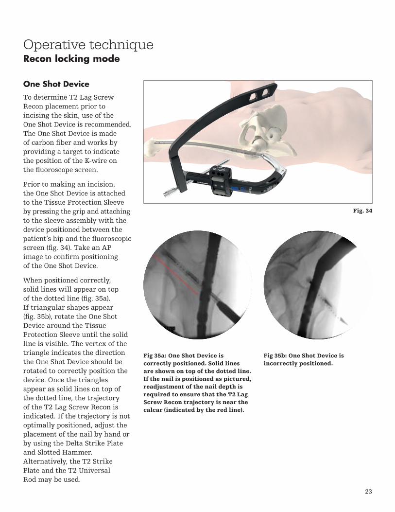
One Shot Device
To determine T2 Lag Screw Recon placement prior to incising the skin, use of the One Shot Device is recommended. The One Shot Device is made of carbon fiber and works by providing a target to indicate the position of the K-wire on the fluoroscope screen.
Prior to making an incision, the One Shot Device is attached to the Tissue Protection Sleeve by pressing the grip and attaching to the sleeve assembly with the device positioned between the patient’s hip and the fluoroscopic screen (fig. 34). Take an AP image to confirm positioning of the One Shot Device.
When positioned correctly, solid lines will appear on top of the dotted line (fig. 35a). If triangular shapes appear (fig. 35b), rotate the One Shot Device around the Tissue Protection Sleeve until the solid line is visible. The vertex of the triangle indicates the direction the One Shot Device should be rotated to correctly position the device. Once the triangles appear as solid lines on top of the dotted line, the trajectory of the T2 Lag Screw Recon is indicated. If the trajectory is not optimally positioned, adjust the placement of the nail by hand or by using the Delta Strike Plate and Slotted Hammer. Alternatively, the T2 Strike Plate and the T2 Universal Rod may be used.
Fig 35a: One Shot Device iscorrectly positioned. Solid linesare shown on top of the dotted line. If the nail is positioned as pictured, readjustment of the nail depth is required to ensure that the T2 Lag Screw Recon trajectory is near the calcar (indicated by the red line).
Fig 35b: One Shot Device isincorrectly positioned.
Fig. 34
24
Operative technique
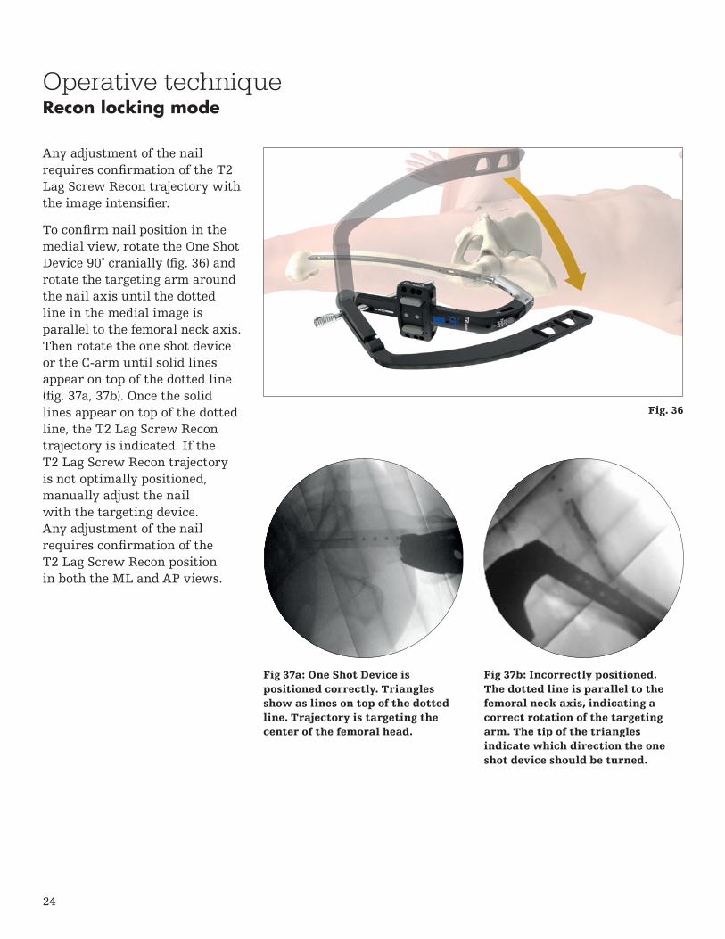
Any adjustment of the nail requires confirmation of the T2 Lag Screw Recon trajectory with the image intensifier.
To confirm nail position in the medial view, rotate the One Shot Device 90º cranially (fig. 36) and rotate the targeting arm around the nail axis until the dotted line in the medial image is parallel to the femoral neck axis. Then rotate the one shot device or the C-arm until solid lines appear on top of the dotted line (fig. 37a, 37b). Once the solid lines appear on top of the dotted line, the T2 Lag Screw Recon trajectory is indicated. If the T2 Lag Screw Recon trajectory is not optimally positioned, manually adjust the nail with the targeting device. Any adjustment of the nail requires confirmation of the T2 Lag Screw Recon position in both the ML and AP views.
Fig 37a: One Shot Device is positioned correctly. Triangles show as lines on top of the dotted line. Trajectory is targeting the center of the femoral head.
Fig 37b: Incorrectly positioned. The dotted line is parallel to the femoral neck axis, indicating a correct rotation of the targeting arm. The tip of the triangles indicate which direction the one shot device should be turned.
Recon locking mode
Fig. 36

25
Operative techniqueRecon locking mode
T2 Lag Screw Recon Placement
Once the position of the nail and the screw trajectory has been verified, make a small skin incision at the site of sleeve entry and advance the sleeves through the incision until the tip contacts the lateral cortex. Ensure that the paddle tip of the sleeve assembly is positioned along the frontal plane and is fully seated on the bone. The grips of the K-wire and tissue protection sleeves must be positioned as shown to ensure that the second set of sleeves can be inserted without interference. Turn the Recon Knob to “A” to lock the sleeve assembly.
Using a power tool, insert the Drill Tip Recon K-wire or the Threaded tip recon K-wire into the K-wire sleeve and through the lateral cortex (fig. 38). Advance the K-wire until the subchondral bone of the femoral head has been reached.
Use imaging to verify that the K-wire is placed along the calcar region in the AP view and central in the ML view.
Verify position of K-wire in both planes before lag screw drilling.
Do not advance K-wire into the pelvis.
Fig. 38

26
Operative technique
If the K-wire is positioned incorrectly, remove the K-wire and correct the nail position by rotating the targeting arm while avoiding applying soft tissue pressure, or by adjusting the depth of the nail. If a more proximal position is required, the Delta Strike Plate may be threaded into the targeting arm and backslapping may be performed using the Slotted Hammer to carefully extract the assembly (fig. 39). Alternatively, the T2 Universal Rod may be used.
Any adjustments to the nail require verification of K-wire placement with fluoroscopic.
The final position of the K-wire should indicate the position of the lag screw tip. Once the K-wire has been correctly positioned, the screw length can be determined by pulling the recon K-wire Sleeve off the bone until the proximal end is flush with the end of the K-wire (fig. 40, fig. 41). The number next to the grip of the tissue protection sleeve indicates the appropriate reaming depth and length of the inferior T2 Lag Screw Recon measured from the tip of the K-wire.
Recon locking mode
Wire sleeve is flush with the K-wire
Depth marking for appropriate screw length
Fig. 39
Fig. 40
Fig. 41
27
Operative techniqueRecon locking mode
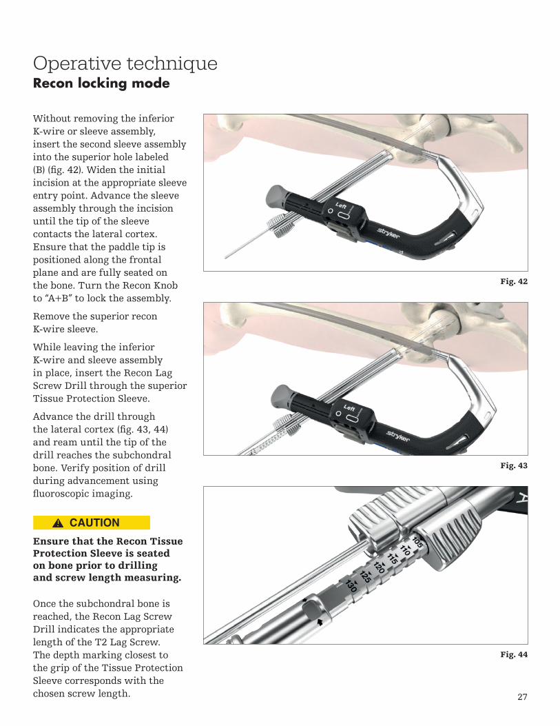
Without removing the inferior K-wire or sleeve assembly, insert the second sleeve assembly into the superior hole labeled (B) (fig. 42). Widen the initial incision at the appropriate sleeve entry point. Advance the sleeve assembly through the incision until the tip of the sleeve contacts the lateral cortex. Ensure that the paddle tip is positioned along the frontal plane and are fully seated on the bone. Turn the Recon Knob to “A+B” to lock the assembly.
Remove the superior recon K-wire sleeve.
While leaving the inferior K-wire and sleeve assembly in place, insert the Recon Lag Screw Drill through the superior Tissue Protection Sleeve.
Advance the drill through the lateral cortex (fig. 43, 44) and ream until the tip of the drill reaches the subchondral bone. Verify position of drill during advancement using fluoroscopic imaging.
Ensure that the Recon Tissue Protection Sleeve is seated on bone prior to drilling and screw length measuring.
Once the subchondral bone is reached, the Recon Lag Screw Drill indicates the appropriate length of the T2 Lag Screw. The depth marking closest to the grip of the Tissue Protection Sleeve corresponds with the chosen screw length.
Fig. 42
Fig. 43
Fig. 44

28
Operative techniqueRecon locking mode
The depth stop of the drill can be used to limit drilling to a value smaller than measured with the inferior K-wire.
Select the appropriate T2 Lag Screw Recon and insert the T2 Lag Screw Recon through the superior Tissue Protection Sleeve using the recon lag screwdriver bit and delta handle assembly (fig. 45).
Thread the screw through the bone and into the femoral head until the subchondral bone is reached. The screw is nearing its proper seating position when the black marking on the driver approaches the end of the tissue protection sleeve. Take an image to verify that the screw head is positioned as desired.
To insert the inferior T2 Lag Screw Recon, remove the inferior K-wire and K-wire sleeve and perform drilling using the technique previously described.
Insert the inferior T2 Lag Screw Recon using the Recon Lag Screwdriver. Take an image to verify that both T2 Lag Screws Recon are positioned as desired and remove the inferior sleeve.
Once both T2 Lag Screws Recon have been inserted (fig. 46), guided distal locking or freehand distal locking should be performed. See relevant section for instructions.
Damage of the nail during drilling may reduce the fatigue strength of the implant which could cause the nail to break.
Fig. 45
Fig. 46

29
Transverse static: (fig. 48)
Round ML Static
Oblong ML Static (Inferior position)
T2 Alpha Femoral Nails offer several options for guided proximal locking in antegrade mode. When performing proximal ML locking, the LEFT side of the targeting arm femur antegrade must be used for a left nail and the RIGHT side for a right nail.
Static Mode
For static proximal locking, the following combinations can be used:
Oblique static: (fig. 47)
Round ML Static
Oblique Static
1
4
1
2
Operative techniqueAntegrade proximal locking mode
Fig. 47
Fig. 48
221
14

30
3
3
1
Operative techniqueAntegrade proximal locking mode
Dynamic mode
In controlled dynamic mode and / or controlled internal apposition / compression mode, use of the dynamic hole is required (fig. 49).
Oblong ML dynamic (superior position)
Internal apposition /compression & external apposition / compression
In internal and external compression modes, use of the dynamic hole is required (fig. 50).
Fig. 49
Fig. 50
Use of an additional ML static locking screw is recommended after active compression has been applied.
Oblong ML dynamic (superior position)
Round ML static (recommended)
3
31
Dynamic locking might be associated with bone shortening during the healing period. Simultaneous utilization of distal and proximal dynamization option could lead to unintended bone shortening.

31
Operative techniqueAntegrade proximal locking mode
Guided proximal lockingThe Tissue Protection Sleeve, Long together with the Drill Sleeve, Long and Trocar, Long (fig. 51) are positioned through the appropriate hole in the targeting arm. Make a small skin incision at the sleeve entry point and advance the assembly through the incision until contact is made with the lateral cortex (fig. 52). If using the Locking Scalpel, push the sleeve assembly against the skin to leave a mark, remove the sleeves and insert the scalpel through the appropriate hole of the targeting arm and make an incision to accommodate the path of the sleeve (fig. 53). Then advance the sleeve assembly through the incision until it is in contact with the lateral cortex. Fully seat the tissue protection sleeve on the cortex. This will drive the head of the trocar from the sleeve assembly (fig. 53). Remove the trocar and ensure that the paddle tip of the tissue protection sleeve is positioned in the frontal plane is fully seated on the bone (fig. 54).
Avoid applying soft tissue pressure to the sleeve assembly prior to the skin incision.
Fig. 51
Fig. 52
Fig. 53
Fig. 54 - Drill sleeve and tissue protection sleeve seated on bone
To prevent skiving ofthe sleeve while ensuringbone contact for correctscrew measurement, ensurethat neither excessive norinsufficient forces areapplied to the sleeve.

32
Operative techniqueAntegrade proximal locking mode
Advance the 4.2 x 360mm locking drill through the drill sleeve and onto the cortex (fig. 55). Drill both cortices. Position the drill tip at the desired final position of the screw tip. Determine screw measurement by rotating the grip of the drill sleeve and pulling the sleeve towards the drill attachment until the sleeve hits the stop. Read the measurement on the drill sleeve at the junction of the tissue protection sleeve (fig. 56).
Ensure sleeve assembly is seated on bone prior to drilling and screw length measuring. Verify correct position of sleeve under imaging prior to drilling
The gray friction lockmechanism is designedto maintain the position ofthe drill sleeves. To removethe sleeve assembly fromthe Targeting Arm FemurAntegrade, press the graymechanism while pullingthe sleeves and trocar.
Drilling past the medial cortex may damage soft tissue.
Fig. 55
Fig. 56
Applying excessive force may result in breakage of the drill which could require recovery. Recovery could result in an iatrogenic fracture and/or bone damage may occur.
33
Operative techniqueAntegrade proximal locking mode
Fig. 57 - Depth marking for appropriate screw length
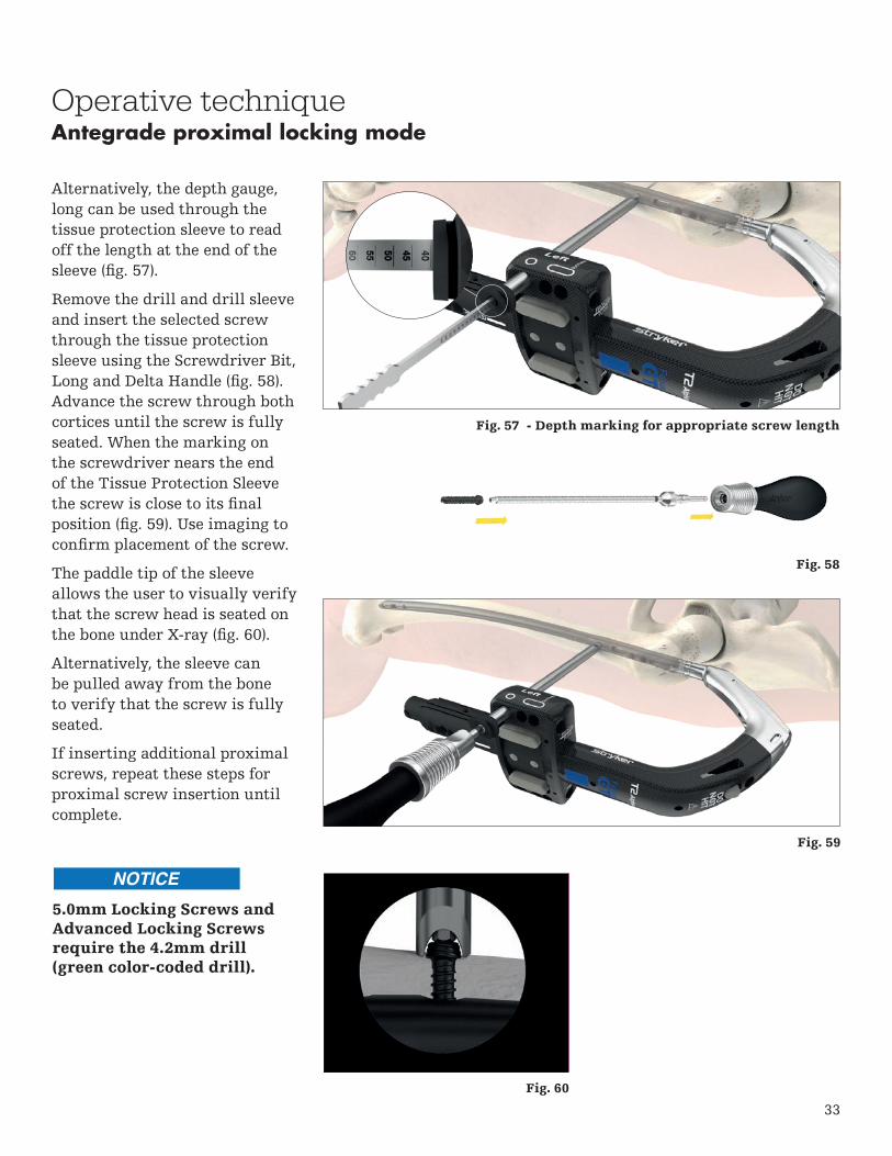
Alternatively, the depth gauge, long can be used through the tissue protection sleeve to read off the length at the end of the sleeve (fig. 57).
Remove the drill and drill sleeve and insert the selected screw through the tissue protection sleeve using the Screwdriver Bit, Long and Delta Handle (fig. 58). Advance the screw through both cortices until the screw is fully seated. When the marking on the screwdriver nears the end of the Tissue Protection Sleeve the screw is close to its final position (fig. 59). Use imaging to confirm placement of the screw.
The paddle tip of the sleeve allows the user to visually verify that the screw head is seated on the bone under X-ray (fig. 60).
Alternatively, the sleeve can be pulled away from the bone to verify that the screw is fully seated.
If inserting additional proximal screws, repeat these steps for proximal screw insertion until complete.
Fig. 60
Fig. 58
Fig. 59
5.0mm Locking Screws and Advanced Locking Screws require the 4.2mm drill (green color-coded drill).
34
Operative techniqueInternal apposition / compression mode
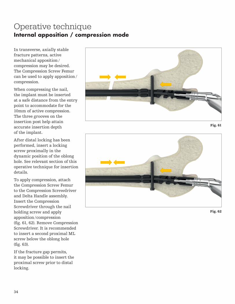
In transverse, axially stable fracture patterns, active mechanical apposition /compression may be desired. The Compression Screw Femur can be used to apply apposition /compression.
When compressing the nail, the implant must be inserted at a safe distance from the entry point to accommodate for the 10mm of active compression. The three grooves on the insertion post help attain accurate insertion depth of the implant.
After distal locking has been performed, insert a locking screw proximally in the dynamic position of the oblong hole. See relevant section of this operative technique for insertion details.
To apply compression, attach the Compression Screw Femur to the Compression Screwdriver and Delta Handle assembly. Insert the Compression Screwdriver through the nail holding screw and apply apposition / compression (fig. 61, 62). Remove Compression Screwdriver. It is recommended to insert a second proximal ML screw below the oblong hole (fig. 63).
If the fracture gap permits, it may be possible to insert the proximal screw prior to distal locking.
Fig. 61
Fig. 62

35
Operative techniqueInternal apposition / compression mode
Apposition / compression must be carried out under X-ray control. Over-compression may cause the nail or screw to fail.
The Compression Screw must be screwed in correctly and with reasonable force to provide desired function and to avoid damage of implants/instruments. Deformation of the Locking Screw may indicate unreasonable force.
When using the compression screw femur, the proximal oblique locking hole cannot be used.
Remove the guide wire prior to drilling or Recon K-wire insertion.
Fig. 63Initial signs of screw bending indicate that sufficient compression has been achieved.

36
Operative techniqueExternal compression mode
As an alternative to internal compression, the External Compression Device Femur can be used to apply apposition / compression.
After two static locking screws have been inserted distally, insert a locking screw proximally in the dynamic position of the oblong hole.
To apply compression, attach the External Compression Device, femur to the Quick Lock Delta Handle (fig. 64) and insert the compression device through the nail holding screw to engage the internal threads of the nail. Rotate the external compression device femur to apply compression (fig. 65, 66).
When compressing the fragments, the implant must be inserted at a safe distance from the entry point to accommodate up to 10mm of active compression. The three grooves on the insertion post help attain accurate insertion depth of the implant.
After apposition / compression has been achieved, insertion of a second proximal screw in the static ML hole is recommended to maintain the compression. Once the second screw has been inserted, the external compression device can be detached. If the fracture gap permits, it may be possible to perform insert the proximal screw prior to distal locking.
Fig. 64
Fig. 65
Fig. 66

37
Fig. 67
Operative techniqueGuided distal locking
Introduction
Use of the Distal Targeting Arm Femur Antegrade is an alternative to the perfect circle technique and is recommended when performing distal locking of the ML screws.
The distal AP screw requires freehand distal locking.
Adjusting Device Femur
Distal Targeting Arm Femur Antegrade

38
Operative techniqueGuided distal locking
Assembly
To assemble, first insert the center pin of the Adjusting Device Femur through the hole of the Distal Targeting Arm Femur Antegrade that corresponds with the selected nail length (fig. 68). Turn knob to lock into position.
Then, slide the opening of the Distal Targeting Arm Femur Antegrade through the Proximal Targeting Arm Femur Antegrade (fig. 69). A click will be felt when the distal targeting arm is correctly positioned. Tighten the fixation knob to secure.
Prior to intra-operative assembly, it is recommended to preassemble the device to perform length verification. Intra-operative assembly should be performed after nail insertion just prior to distal screw insertion.
Center Pin
Fig. 68
Fig. 69

39
Guided distal locking includes the following steps:
1. Pre-operative Length Verification
2. Oblique C-Arm Positioning
3. Height and Orbital Rotation of the C-arm
4. Sleeve Adjustment
5. Locking
Step 1: Pre-operative Length Verification
To ensure that the adjusting device is correctly assembled to the targeting arm, pre-operative length verification is recommended prior to nail insertion. On the back table, assemble the distal targeting arm and insert the tissue protection sleeve into the most proximal of the distal holes of the Adjusting Device and confirm correct alignment with nail (fig. 70). If the sleeve is aligned, disassemble the distal targeting arm from the proximal targeting arm and place on the back table. Do not disassemble the adjusting device.
Proceed with nail and proximal screw insertion as required, and reassemble Distal Targeting Arm Femur Antegrade prior to distal ML screw insertion.
Operative technique
Fig. 70
Guided distal locking
Sleeve aligned with hole of nail

40
30º
K-wire
Operative techniqueGuided distal locking
Step 2: Oblique C-arm Positioning
To perform the guided distallocking, it is essential to placethe X-ray beam of a C-armapproximately 30º oblique to theaxis of the drill sleeve assembly(fig. 71).
As an option, the K-wire3 x 285mm can be insertedfrom the lateral opening of the Adjusting Device. Thiswire indicates 30º oblique to theaxis of the drill sleeve assemblyand helps to adjust the C-arm.
Fig. 71
41
X-ray tube
12
Operative techniqueGuided distal locking
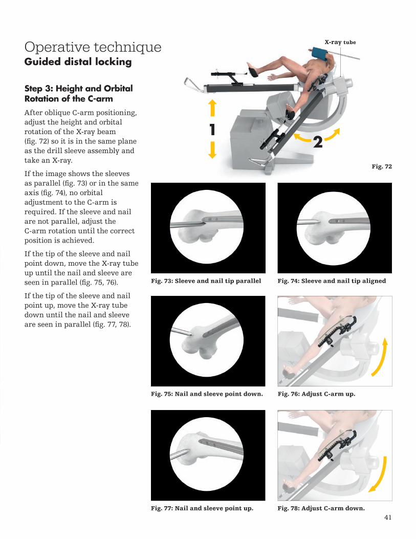
Step 3: Height and Orbital Rotation of the C-arm
After oblique C-arm positioning, adjust the height and orbital rotation of the X-ray beam (fig. 72) so it is in the same plane as the drill sleeve assembly and take an X-ray.
If the image shows the sleeves as parallel (fig. 73) or in the same axis (fig. 74), no orbital adjustment to the C-arm is required. If the sleeve and nail are not parallel, adjust the C-arm rotation until the correct position is achieved.
If the tip of the sleeve and nail point down, move the X-ray tube up until the nail and sleeve are seen in parallel (fig. 75, 76).
If the tip of the sleeve and nail point up, move the X-ray tube down until the nail and sleeve are seen in parallel (fig. 77, 78).
Fig. 73: Sleeve and nail tip parallel
Fig. 75: Nail and sleeve point down. Fig. 76: Adjust C-arm up.
Fig. 77: Nail and sleeve point up. Fig. 78: Adjust C-arm down.
Fig. 74: Sleeve and nail tip aligned
Fig. 72
42
Operative techniqueGuided distal locking
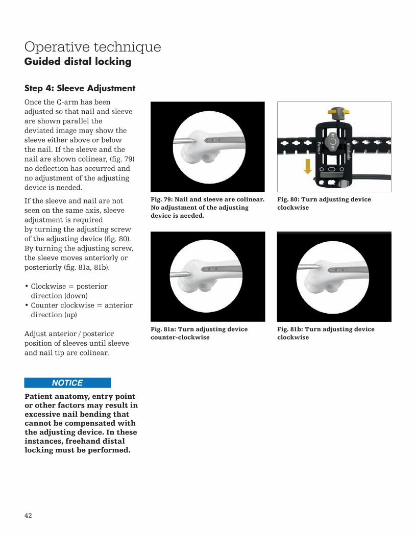
Step 4: Sleeve Adjustment
Once the C-arm has beenadjusted so that nail and sleeveare shown parallel thedeviated image may show thesleeve either above or belowthe nail. If the sleeve and thenail are shown colinear, (fig. 79)no deflection has occurred and no adjustment of the adjusting device is needed.
If the sleeve and nail are notseen on the same axis, sleeve adjustment is requiredby turning the adjusting screwof the adjusting device (fig. 80).By turning the adjusting screw,the sleeve moves anteriorly orposteriorly (fig. 81a, 81b).
• Clockwise = posteriordirection (down)
• Counter clockwise = anteriordirection (up)
Adjust anterior / posteriorposition of sleeves until sleeve and nail tip are colinear.
Fig. 79: Nail and sleeve are colinear. No adjustment of the adjusting device is needed.
Fig. 80: Turn adjusting device clockwise
Fig. 81a: Turn adjusting device counter-clockwise
Fig. 81b: Turn adjusting device clockwise
Patient anatomy, entry point or other factors may result in excessive nail bending that cannot be compensated with the adjusting device. In these instances, freehand distal locking must be performed.

43
Guided distal lockingOperative technique
Step 5: Locking
Once the sleeve has been correctly positioned, incise the skin at the sleeve entry point. Ensure that the incision is straight to avoid forces on the sleeve. Advance the assembly through the incision until contact is made with the lateral cortex (fig. 82).
Once distal drilling and locking commences, the operative steps are the same as when performing guided proximal locking.
Then reinsert the sleeve assembly into the hole and advance the assembly through the incision until it is in contact with the lateral cortex.
Avoid soft tissue pressure tothe sleeve assembly prior tothe skin incision.
Fig. 82
44
Operative technique
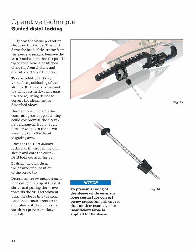
Fully seat the tissue protection sleeve on the cortex. This will drive the head of the trocar from the sleeve assembly. Remove the trocar and ensure that the paddle tip of the sleeve is positioned along the frontal plane and are fully seated on the bone.
Take an additional X-ray to confirm positioning of the sleeves. If the sleeves and nail are no longer in the same axis, use the adjusting device to correct the alignment as described above.
Unintentional contact after confirming correct positioning could compromise the sleeve /nail alignment. Do not apply force or weight to the sleeve assembly or to the distal targeting arm.
Advance the 4.2 x 360mm locking drill through the drill sleeve and onto the cortex. Drill both cortices (fig. 83).
Position the drill tip at the desired final position of the screw tip.
Determine screw measurement by rotating the grip of the drill sleeve and pulling the sleeve towards the drill attachment until the sleeve hits the stop. Read the measurement on the drill sleeve at the junction of the tissue protection sleeve (fig. 84).
Fig. 84
Guided distal Locking
To prevent skiving ofthe sleeve while ensuringbone contact for correctscrew measurement, ensurethat neither excessive norinsufficient force is applied to the sleeve.
Fig. 83

45
Operative technique
Alternatively, the Depth Gauge, Long can be used through the tissue protection sleeve to read off the length at the end of the sleeve (fig. 85). To use, remove the drill sleeve and pass the depth gauge, long through the tissue protection sleeve and hook the distal end of the gauge onto the far cortex. Read the measurement on the depth gauge closest to the end of the tissue protection sleeve.
Remove the drill and drill sleeve, and insert the selected screw through the tissue protection sleeve using the screwdriver bit, long with the quick lock delta handle (fig. 86). Advance the screw through both cortices until the screw is fully seated. Use imaging to confirm placement of screw.
To insert an additional ML screw(s), use the image intensifier to align the sleeves and repeat the aforementioned steps for sleeve adjustment, drilling and screw insertion.
Freehand distal locking must be used to insert a screw in the distal AP hole.
Guided distal Locking
Fig. 85
Fig. 86

46
Operative techniqueFreehand distal locking
As an alternative to distal targeting, the freehand technique may be used to insert the locking screws.
The critical step with any freehand locking technique is to visualize a perfectly round locking hole or perfectly oblong locking hole with the C-arm (fig. 87, 88).
After making an incision (fig. 89, 90), the freehand drill is held at an oblique angle to the center of the locking hole.
Upon X-ray verification, the drill is placed perpendicular to the nail and drilled through the lateral and medial cortex. Confirm in both the anterior and lateral planes by X-ray that the freehand drill passes through the hole in the nail.
Use the screw scale with the freehand drill to read off the screw length directly at the color coded marking (fig. 91).
Alternatively, the freehand depth gauge long or freehand depth gauge short may be used after drilling to determine the required screw length (fig. 92).
Fig. 87: Locking hole is not perfectly circular. The C-arm is incorrectly positioned.
Fig. 88: Locking hole is perfectly circular. The C-arm is correctly positioned.
Fig. 89 Fig. 90
Fig. 91
Fig. 92

47
Operative techniqueFreehand distal locking
Routine locking screw insertion is employed with screwdriver bit, self retaining sleeve and delta handle assembly (fig. 93).
The self-retaining screwdriver assembly may be used to facilitate freehand locking. To use, assemble the Self-Retaining Screwdriver Sleeve to the Screwdriver Bit, and Quick Lock Delta Handle and attach the screwdriver to the screw. Secure the connection by turning the sleeve counterclockwise (fig. 94).
Take care to avoid capturing soft tissue during freehand drilling.
Fig. 93
Fig. 94

48
Ø4.5mm
Ø5.3mm
Ø5.7mm
Operative techniqueAdvanced locking screws
When used with the T2 Alpha Antegrade Femoral Nails, the Advanced Locking Screws are designed to limit the relative axial and angular movement between the nail and screw construct. The respective implants are designed to increase construct stability within unstable fracture patterns and/or poor bone quality conditions.
The effect of axial stability between nail and Advanced Locking Screw is achieved by a threaded interface. Insertion characteristics of the Advanced Locking Screws might be susceptible to user-related parameters such as drilling angulation or translational offsets during the pre-drilling and insertion processes. Anatomic conditions such as bone quality and cortical bone dimensions might also influence screw insertion.
Encountering elevated insertions torques caused by one or more of the above-mentioned parameters might indicate that axial stable locking might not be necessary. Carefully observe the torque during the screw insertion process and be prepared to switch to a standard locking screw if excessive force is required. Advanced Locking Screws may be inserted in any 5mm circular hole of the nail; they cannot be used in the dynamic / oblong holes. The near cortex must be overdrilled prior to insertion of the Advanced Locking Screws.
Colors indicate where Advanced Locking Screws can be utilized. Advanced Locking Screws are not accepted in the oblong or recon holes of the nail.
49
Operative techniqueAdvanced locking screws
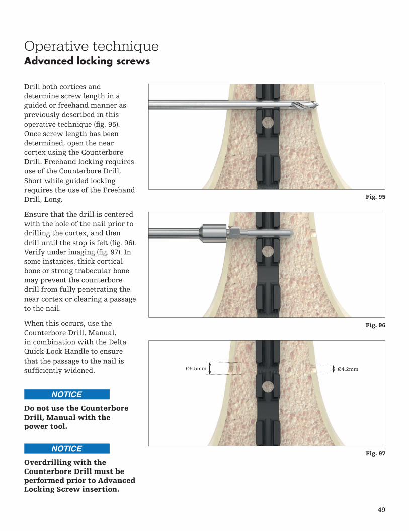
Drill both cortices and determine screw length in a guided or freehand manner as previously described in this operative technique (fig. 95). Once screw length has been determined, open the near cortex using the Counterbore Drill. Freehand locking requires use of the Counterbore Drill, Short while guided locking requires the use of the Freehand Drill, Long.
Ensure that the drill is centered with the hole of the nail prior to drilling the cortex, and then drill until the stop is felt (fig. 96). Verify under imaging (fig. 97). In some instances, thick cortical bone or strong trabecular bone may prevent the counterbore drill from fully penetrating the near cortex or clearing a passage to the nail.
When this occurs, use the Counterbore Drill, Manual, in combination with the Delta Quick-Lock Handle to ensure that the passage to the nail is sufficiently widened. Ø5.5mm Ø4.2mm
Do not use the Counterbore Drill, Manual with the power tool.
Overdrilling with the Counterbore Drill must be performed prior to Advanced Locking Screw insertion.
Fig. 95
Fig. 96
Fig. 97

50
Operative techniqueAdvanced locking screws
To use the Counterbore Drill, Manual, insert the drill into the path created by the first counterbore drill and turn the drill in a gentle clockwise motion with moderate axial pressure until the pathway to the nail has been opened (fig. 98).
Once drilling has been completed, insert the Advanced Locking Screw with gentle axial force using the appropriate screwdriver through the near cortex without turning the screw, while ensuring that the axis of the screw is aligned with the corresponding locking hole.
Push the screw until the leading tip is engaged with the nail hole. X-ray verification can be used to confirm position.
To confirm correct starting point and axial alignment of the screw, gently rotate the screw counterclockwise while applying gentle axial force (fig. 99). A click sound or snapping of the thread indicates that the screw is in the correct position. Once position has been confirmed, insert the screw by rotating clockwise until the screw is fully seated (fig. 100). Use X-ray to confirm.
The Advanced Locking Screw must be inserted using reasonable force
to provide desired function and to avoid damaging the screw. If unreasonable insertion torque is noticed, stop insertion, turn the screw counterclockwise
and then attempt to insert the screw. If unreasonable insertion torque is still noticed, remove the screw and proceed with a Locking Screw.
Fig. 98
Fig. 99
Fig. 100

51
Operative techniqueSet screw and end cap insertion
After removal of the target device, a set screw or end cap can be used.
The Set Screw GT or Set Screw PF is designed to tighten down on the proximal T2 Lag Screw Recon or the oblique locking screw. If a set screw is used, an end cap cannot be inserted. The End Cap GT/PF or End Cap Lower Extremity are available to adjust nail length. After imaging confirms satisfactory reduction and hardware implantation the set screw can be inserted with the Screwdriver Bit and Quick-Lock Delta Handle assembly (fig. 101).
The end cap can be inserted with the Screwdriver Bit, Long and Quick Lock Delta Handle assembly (fig. 102) or with the Compression Screwdriver. Optionally, the end cap can be inserted over any K-wire with a diameter of 3.2mm or less.
Ensure that the end cap or set screw is fully seated to minimize the potential risk for loosening.
Fig. 101
Fig. 102

52
Operative technique
The set screw or end cap is removed with the Screwdriver Bit, Long and Quick-Lock Delta Handle Assembly. To remove the nail, first assemble the Extraction Shaft and the Delta Strike Plate by threading the Delta Strike Plate into the nail. The cannulated extraction shaft is inserted into the driving end of the nail. All locking screws are removed with the standard screwdriver bit. If necessary, the compression screw should be loosened and removed with the Compression Screwdriver.
For removal of the T2 Lag Screw Recon, use the Recon Lag Screwdriver Rod together with the Spreading Recon Lag Screwdriver Bit.
Use the Slotted Hammer with the Extraction Shaft and Delta Strike Plate to extract the nail in a controlled manner (fig. 103). Alternatively, the T2 Universal Rod may be connected to the Extraction Shaft.
Stryker offers a universal implant extraction set that is not compatible with the T2 Alpha Femoral Nail GT or Femoral Nail PF. Use of the T2 Alpha Extraction Shaft is required for removal. The universal implant extraction set may be used for removal of IMN Screws or other internal fixation systems.
The T2 Alpha femoral nail is designed for temporary implantation until bone consolidation occurs. If bone consolidation does not occur or if the consolidation is insufficient, the implant may break. The aim of post- operative care must be to ensure the promotion of bone consolidation.
The T2 Alpha femoral nail is not intended for full weight bearing in patients with complex unstable fractures until bone consolidation is confirmed in the follow-up X-rays.
Fig. 103
Nail removal

53
Notes

54
Notes

55
Notes

This document is intended solely for the use of healthcare professionals. A surgeon must always rely on his or her own professional clinical judgment when deciding whether to use a particular product when treating a particular patient. Stryker does not dispense medical advice and recommends that surgeons be trained in the use of any particular product before using it in surgery.
The information presented is intended to demonstrate a Stryker product. A surgeon must always refer to the package insert, product label and/or instructions for use, including the instructions for cleaning and sterilization (if applicable), before using any Stryker product. Products may not be available in all markets because product availability is subject to the regulatory and/or medical practices in individual markets. Please contact your Stryker representative if you have questions about the availability of Stryker products in your area.
Stryker Corporation or its divisions or other corporate affiliated entities own, use or have applied for the following trademarks or service marks: Stryker, T2 Alpha. All other trademarks are trademarks of their respective owners or holders.
Content ID: T2-ST-17_Rev-5, 02-2019
Copyright © 2018 Stryker
Manufacturer:
Stryker Trauma GmbH Prof.-Küntscher-Str. 1-5 24232 Schönkirchen Germany
stryker.com