tm 11-5820-474-14 department of the army technical...
TRANSCRIPT

TM 11-5820-474-14
DEPARTMENT OF THE ARMY TECHNICAL MANUAL
OPERATOR'S, ORGANIZATIONAL,DIRECT SUPPORT, AND GENERAL SUPPORT
MAINTENANCE MANUAL
RADIO SET AN/GRC-109
(NSN 5820-00-892-0881:)
This copy is a reprint which includes current:,pages from Changes 4 through 6.'
HEADQUARTERS, DEPARTMENT OF THE ARMY18 MAY 1962

TM 11-5820-474-14
RADIATION HAZARD
STD-RW-2
Tube type OB2 used in this radio set containsradioactive material. This tube is potentially hazardouswhen broken: see qualified medical personnel and thesafety director if you are exposed to or cut by brokentubes. Use extreme care in replacing these tubes (para87) and follow safe procedures in their handling,storage, and disposal (para 38.3)
Never place radioactive tubes in your pocket. Useextreme care not to break radioactive tubes whilehandling them. Never remove radioactive tubes fromcartons until ready to use them. Refer to paragraph38.3 on handling, storage, and disposal of radioactivematerial.
WARNING
DANGEROUS VOLTAGES EXIST IN THIS EQUIPMENTBe extremely careful when servicing the power supplies and transmitter; voltage above 450 volts may be present. Takecare not to contact the ac power source when connecting power supplies; voltages up 260 may be encountered.
WARNING
When selenium rectifiers fail because of burnout or arc-over, poison fuses and component fumes and compounds arereleased. The fumes have a strong odor and must not be inhaled. Provide adequate ventilation immediately and do nothandle the rectifier until it has cooled.
DON’T TAKE CHANCES!

TM 11-5820-474-14
TECHNICAL MANUAL HEADQUARTERSDEPARTMENT OF THE ARMY
No. 11-5820-474-14 WASHINGTON 25, DC, 18 May 1962
OPERATOR'S, ORGANIZATIONAL, DIRECT SUPPORT AND GENERAL SUPPORT
MAINTENANCE MANUAL
RADIO SET AN/GRC-109
(NSN 5820-00-892-0881)
Paragraph PageCHAPTER 1. INTRODUCTIONSection I. General ............................................................................................... 1, 2 3
II Description and data .......................................................................... 3 - 10 3 - 10CHAPTER 2. INSTALLATION ................................................................................. 11- 15 11 - 15
3. OPERATING INSTRUCTIONSSection I. Operating controls and indicators ....................................................... 16, 17 17
II. Operation under usual conditions ........................................................ 18 - 26 20 - 22III. Operation under unusual conditions .................................................... 27 - 29 23
CHAPTER 4. OPERATOR'S MAINTENANCE ......................................................... 30 - 34 24 - 265. SECOND ECHELON MAINTENANCE ............................................... 35 - 40 316. THEORY
Section I. Theory of Radio Transmitter T-784/GRC-109 ..................................... 41 - 46 34, 35II. Theory of Radio Receiver R-1004/GRC-109 ....................................... 47 - 53 36 - 38
III. Theory of Power Supply PP-2684/GRC-109........................................ 54 - 58 39 - 42IV. Theory of Power Supply PP-2685/GRC-109........................................ 59, 60 42
CHAPTER 7. TROUBLESHOOTINGSection I. General troubleshooting techniques ................................................... 61 - 63 44, 45
II Troubleshooting Radio Receiver R-1004/GRC-109 ............................ 64 - 69 45 - 56III. Troubleshooting Radio Transmitter T-784/GRC-109 ........................... 70 - 75 56, 57IV. Troubleshooting Power Supply PP-2684/GRC-109 ............................. 76 - 80 63 - 65V. Troubleshooting Power Supply PP-2685/GRC-109.............................. 81 - 84 69, 70
VI. Troubleshooting Voltage Regulator CN-690/GRC-109......................... 85, 86 73CHAPTER 8. REPAIRS AND ALIGNMENT ............................................................. 87 - 92 75 - 77
9. FOURTH ECHELON TESTING PROCEDURES ................................. 93 - 107 78 - 105APPEND I. REFERENCES ................................................................................... 108
II. MAINTENANCE ALLOCATION .......................................................... 109III. BASIC ISSUE ITEMS LIST ................................................................ 113
INDEX ........................................................................................................... 135
Change 6 1

TM 11-5820-474-14
Figure 1. Radio Set AN/GRC-109 in operation.
Change 6 2

TM 11-5820-474- 14
CHAPTER 1
INTRODUCTION
Section I. GENERAL
1. Scope
This manual contains instructions for the installation,operation, maintenance, and repair of Radio SetAN/GRC-109 (fig. 1). It also includes three appendixeswhich list references, the basic issue items list and itemstroop installed or authorized list, and maintenanceallocation.
1.1. Indexes of Publications
a. DA Pam 310-4. Refer to the latest issue of DAPam 310-4 to determine whether there are new editions,changes, or additional publications pertaining to theequipment.
b. DA Pam 310-7. Refer to DA Pam 310-7 todetermine whether there are modification work orders(MWO's) pertaining to the equipment.
2. Forms and Records
a. Reports of Maintenance and UnsatisfactoryEquipment. Maintenance forms, records, and reportswhich are to be used by maintenance personnel at allmaintenance levels are listed in and prescribed by TM38-750 (Army).
b. Report of Packaging and Handling Deficiencies.Fill out and forward DD Form 6 (PackagingImprovement Report) as prescribed in AR 700-58,/NAVSUPINST 4030.29.: AFR 71-13./MCOP4030.29A, and DLAR 4145.8.
c. Discrepancy in Shipment Report (DISREP) (SF361). Fill out and forward Discrepancy in ShipmentReport (DISREP) (SF 361) as prescribed in AR 55-38/NAVSUPINST 4610.33B/ AFR 75-18/MCOP4610.19C, and DLAR 4500.15.
2.1. Destruction of Army
Materiel Demolition and destruction of electronicequipment will be under the direction of the commanderand in accordance with TM 750-244-2.
2.2. Administrative Storage
Prior to or after an administrative storage period,perform the maintenance procedures contained inparagraphs 31 through 33.
2.3. Reporting of Errors
Report of errors, omissions, and recommendations forimproving this publication is authorized and encouraged.Reports should be submitted on DA Form 2028(Recommended Changes to Publications and BlankForms) and forwarded direct to Commander, US ArmyCommunications and Electronics Materiel ReadinessCommand, ATTN: DRSEL-MA-Q, Fort Monmouth, NJ07703.
2.4. Reporting Equipment ImprovementRecommendations (EIR)
EIR's will be prepared using DA Form 2407,Maintenance Request. Instructions for preparing EIR'sare provided in TM 38-750, the Army MaintenanceManagement System. EIR's should be mailed direct toCommander, US Army Communications and ElectronicsMateriel Readiness Command, ATTN: DRSEL-MA-Q,Fort Monmouth, NJ 07703. A reply will be furnisheddirect to you.
Section II. DESCRIPTION AND DATA
3. Purpose and Use
a. Radio Set AN/GRC-109 is a compact, portableradio station used for continuous wave (cw)communications, at distances up to 75 miles, under awide range of climatic conditions. Two power supplies
and a voltage regulator permit operation from a varietyof power sources.
b. Only cw signals can be transmitted, butamplitude-modulated (am) voice and tone signals aswell as cw signals can be received. Transmissions
Change 6 3

TM 11-5820-474-14
can be made by use of a built-in hand key, an externalhand key, or an external high-speed, automatic keyer.
4. Technical Characteristics
a. Radio Transmitter T-784/GRC-109.
Frequency range, 3 to 22 mc:Band 1 ......................................3.0 to 6.0 mc.Band 2 ......................................6.0 to 10.0 mc.Band 3 ...................................... 10.0 to 17.0 mc.Band 4 ......................................17.0 to 22.0 mc.Number of tubes ......................2.Type of transmission Cw.Frequency control .....................Crystal.Distance range .........................Approximately 75
miles1 (121 kilo-meters).
Power requirements .................450 volts dc at 100 ma,and 6.3 volts ac or dcat 1.2 amp.
Power output .............................10 to 15 w, dependingon frequency.
Antenna ...................................Single, horizontal-wire,25 to 75 feet long,depending onfrequency.
1Range will vary considerably according to frequency,terrain, and atmospheric conditions.
b. Radio Receiver R-1004/GRC-109.
Receiver type ............................Superheterodyne.Number of tubes ......................6.Frequency range, 3 to 24 mc:Band 1 ......................................3.0 to 6.0 mc.Band 2 ......................................6.0 to 12 mc.Band 3 ......................................12 to 24 mc.Types of signals ........................Am., cw, and mcw.
received.Sensitivity ................................5 uv for 10-db signal-
to-noise ratio.Intermediate frequency 455 kc.If bandwidth .............................. 9 kc (6 db down).Fixed-frequency opera- Crystal used in localtion. oscillator.Power input ..............................1.3 to 1.5 volts dc
at 300 ma, and 90 to108 volts dc at 20ma.
Power output .............................30 mw audio into a4,000-ohm load.
Antenna ...................................Same as transmitter,or a separate,single-wire2.
2Separate transmitting and receiving antennas mayimprove operation, particularly at lower frequencies.
c. Power Supply PP-2684/GRC-109.
Alternate power inputs:Alternating cur- 75 to 260 volts, 40rent to 400 cycles.Battery, wet-cell 6 volts at 13 amp (keyof not less than down); 660 ampere-hour volts at 5 amp (keycapacity. up).Direct Current 450 volts dc at 115 ma;Generator 6 volts dc at 2.5 amp.G-43 G.Power outputs:For Radio Trans- 450 volts dc at 100mitter T-784 ma; 6.3 volts ac or dcGRC-109. at 1.5 amp.For Radio Re- 108 volts de regulatedceiver R-1004 at 20 ma; 1.5 volts dcGRC-109. regulated at 0.3 amp.For battery 6 volts dc at 3.8 amp.charging.Number of tubes ......................1 (voltage regulator).
d. Power Supply PP-26851/GRC-109.
Power inputs ............................75 to 260 volts ac, 40to 400 cycles.Power outputs:For Radio Trans- 450 volts dc at 100 ma;mitter T-784 6.3 volts ac atGRC-109. 1.5 amp.For Radio Re- 108 volts dc regulatedceiver R-1004 at 20 ma; 1.5 voltsGRC-109. dc regulated at 0.3amp.Number of tubes ......................1 (voltage regulator).
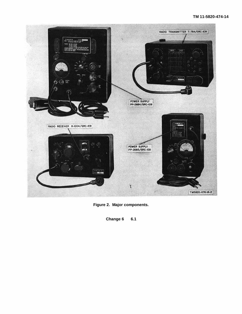
5. Components of Radio Set AN/GRC-109
a. Components (fig. 2). The components of RadioSet AN/GRC-109 are listed in the following table:
Change 6 4

TM 11-5820-474-14
Height Depth Width UnitQuantity Item (in.) (in.) (in.) Weight
(lb)1 .....................Radio Transmitter T-784/GRC-109................ 8-5/8 ....... 5-1/2 ......... 5-7/16 ............. . 91 .....................Radio Receiver R-1004/GRC-109 ................. 8-5/8 ........ .5-1/2 ........ 5-7/16 ............. 101 .....................Power Supply PP-2684/GRC-109 ................. 10. ......... 8-1/2 ......... 5-1/2 ............... .24.51 ......................Power Supply PP-2685/GRC-109 ................. .8-5/8 ...... 5-1/2 ......... 5-7/16 ............. .121 set ................Operating accessories (b below)1 set ................Running spares (c below)
b. Items Comprising an Operable Radio Set FSN QTY Nomenclature, part No., and mfr. codeAN/GRC-109 (FSN 5820-892-0681). Group IRadio Set AN/GRC-109
NOTEThe part number is followed by the applicable 5-digit Federal supply code for manufacturers(FSCM) identified in SB 708-42 and used to identify manufacturer, distributor, or Governmentagency, etc.
Change 6 4.1

TM 11-5820-474-14
b.Items Comprising an Operable Radio Set AN/GRC-109 (FSN 5820-892-0881).
FSN Qty Nomenclature part No., and mfr.code
5820-863-3498 1 Antenna As-1722GRC-109: (Notin-stalled) (Not mounted)
5995-863-3499 1 Cable Assembly, Power,ElectricalCX-11042GRC-109: (Not in-stalled) (Not mounted)
5995-863-3497 1 Cable Assembly, SpecialPurpose,Electrical CY-11041/GRC-109:(Not installed) (Not mounted)
5965-223-4572 1 Headset H465U:(Notinstalled)(Not mounted)
5820-788-5496 1 Maintenance Kit, ElectronicEquipment MK33/GRC-109:(Not installed) (Not mounted)
5820-823-2363 1 Power Supply PP-2684/GRC-109:(Not installed) (Not mounted)
5820-823-2364 1 Power Supply PP-2685/GRC-109:(Not installed) (Not mounted)
5820-892-0882 1 Receiver, Radio R-1004/GRC-109:(Not installed) (Not mounted)
6110-823-2365 1 Regulator, Voltage CN690/GRC-109: (Not installed) (Notmounted)
5820-892-4880 1 Transmitter, RadioT-784/GRC-109:(Not installed) (Not mounted)
6145-548-2742 125 Wire: rubber covered; BeldenWire
ft No. 8898 (1 ea coil 100 t, 1 eacoil25 ft); (Not installed) (Notmounted)Group IIMaintenance Kit, ElectronicEquip-ment MK-833/GRC-109 (RunningSpare Items restoredin this kit in addition to itemslisted below)
6240-864-3330 1 Adapter, Lampholder ToConnectorMX479I2GRC-109
5995-985--8074 1 Adapter, Headset Cable MX-6793/GRC,109
5975-247-4855 1 Clamp, Electrical: and clamp 58;12701
5935-1991-1787 1 Connector, Adapter; lampbaseadapter; SM-B-4&3891; 80063
c. Operating Accessories (fig. 5). The followingoperating accessories are supplied with the radio set.FSN Quantity Item},
1 Technical manuals6110-823-2365 ...1 Voltage Regulator CN-690/
GRC-109
5965-223-4572....1 Headset H45/U1 Maintenance Kit (MK43S/
GRC-109)6145-548-2742 ...100 ft Wire, rubber-covered No. 185820-863-3498 ...1 Antenna AS-172'2GRC-1095995-863-3499 ...1 Cable Assembly, Power, Elec-
trical CX-11042/GRC1096995-863-3497 ...1 Cable Assembly, Special Pur-
pose, Electrical CX-11041/GRC-109
6145-548-2742 ...25 ft Wire, rubber-covered, No. 18Note. The 100-foot and 25-footlengths of No. 18rubbercoveredwire is supplied as a single 125-footlength on contract DA-36-039-AMC04556(E)
d. Maintenance Kit (fig. 4) The following itemscomprise Maintenance Kit, Electrical Equipment MK-833/GRC109.FSN Quantify Item
1 Adapter MX-6792/GRC-109(lampholder)1 Adapter, Headset Cable MX-6793/GRC-109 (headset)
1 Case CY-4621/GRC-1091 Clamp, Electrical (ground)1 Connector, adapter (amp base)1 Knife TL-291 Pliers, long-nosed1 Screwdriver1 Wrench, open end1 Wrench, Allen No. 81 set Running spares (as follows)
5960-166-7648 ..... 2 Electron tube, MIL type OB25960-262-0187 ..... .1 Electron tube, MIL type1L65960-188-3595 ..... 2 Electron tube, MIL type IT45960-892-3460 ..... 1 Electron tube MIL type1U5WA5960-188-8569 ..... 1 Electron tube, MIL type 2E265960-166-7666 ..... 1 Electron tube, MIL type 6AC75960-280-4960 ..... 5 Fuses, 2-amp, type 3AG5920-012-0151 ..... 3 Fuses, 15-amp, type 3AG5970-356-0633 ..... 6 Insulators, white porcelain6240-155-8706 ..... 1 Lamp, incandescent, GE No. 476130-863-3576 ...... 1 Vibrator, 6-volt
6. Nomenclature and Common NamesNomenclature .............................. Common nameRadio Set AN/GRC-109 .............. .Radio setRadio Transmitter ....................... TransmitterT-784iGRC-109.Radio Receiver ........................... ReceiverR-1004/GRC-109Power Supply ............................. . Large power supplyPP-2684/GRC-109.Power Supply ............................. .Small power supplyPP-2685/GRu-iuo.Voltage Regulator . ................... .Voltage regulatorCN-690/GRC- 109.Direct Current Generator ............. Hand-cranked GeneratorG-43/G.Headset H-65/U .......................... .Headset
Change 5 5

TM 11-5820-474-14
7. Description of Radio Set AN/GRC-109
a. The radio set includes a transmitter, a receiver,two power supplies, and a simple antenna system.Figure 2 shows the major components of the radio set,which is portable and requires no mounts. With theexception of the antenna system, the radio set -may beassembled without the use of tools. The majorcomponents are sealed for operation in extremeenvironmental conditions and protected againstexcessive moisture by renewable desiccates.
b. The transmitter and receiver may be operatedfrom either of the two power supplies or from the hand-cranked generator with the addition of the voltageregulator. Permanently attached power cables on thetransmitter and receiver plug into the designatedconnectors on the power supplies or the voltageregulator. The large and small power supplies' canoperate on a variety of alternating-current (ac) voltagesand frequencies. The large power supply can also beoperated from a 6-volt storage battery or the hand-cranked generator. The large power supply alsosupplies 6 volts for recharging the storage battery.Cables and adapters necessary for connecting thepower supplies to various power sources are supplied as
part of the operating accessories. Figure 5 shows allpossible power options for operating the radio : 1 set.
c. A common antenna may be used for both thetransmitter and receiver, or a separate antenna may beused for each of the two components. Break-inoperation is possible when a common antenna is beingused. Slightly better performance may be obtained onlower frequencies by the use of separate antennas.Antenna connections are made to binding posts on thefront panel of the transmitter and receiver.
8. Description of Major Components
a. Radio Transmitter T-7841GRC-109. (fig. 2).The transmitter is a miniature, crystal controlled cwtransmitter that covers 3 to 22 megacycles (me) in fourbands. The power output is 10 to 15 watts, dependingon the operating frequency. The transmitter is tuned bythree front-panel controls with the aid of a tuning chartand tuning lamps. Any single wire system with animpedance of 72 to 1,200 ohms may be used as anantenna A front-panel telegraph key is used for manualoperation. There is also provision for attaching anexternal key or an automatic high-speed keyer. Thetransmitter is housed in a sealed, waterproof case.
Change 5 6
TM 11-5820-474-14
Figure 2. Major components.
Change 6 6.1

TM 11-5820-474-14
Figure 3. Operating accessories.
7

TM 11-5820-474-14
Figure 4. Maintenance Kit, Electrical equipment MK-8333/GRC-109.
8

TM 11-5820-474-14
Figure 5. Primary power options.
9

TM 11-5820-474-14
b. Radio Receiver R-1004/GRC-109 (fig. 2).The receiver is a miniature, Superheterodyne
communications receiver that can receive am., cw, andmodulated continuous wave (mew) signals from 3 to 24me. The range is covered in three 'bands. Provision ismade for fixed-frequency operation by a front-panelplug-in crystal. A frequency dial and a vernier scalepermit accurate tuning. Headphone, ground, andantenna connections are made to the front-panel bindingposts. The receiver is housed in a sealed, waterproofcase.
c. Power Supply PP-2684/GRC-109. The largepower supply (fig. 2) furnishes B + and filamentvoltages for the transmitter and receiver. The voltagessupplied to the receiver are regulated. This powersupply may be operated from either of three powersources: ac, from 75 to 260 volts, 40 to 400 cycles; a 6-volt storage battery; a hand-cranked generator. Inaddition, when operated from ac lines, the large powersupply may be used to recharge a 6-volt storage battery.A meter on the front panel indicates the voltage of theac source to which the power supply is connected. Thelarge power supply is housed in a sealed, waterproofcase.
d. Power Supply PP-2685/GRC-109. The smallpower supply (fig. 2) furnishes B + and filamentvoltages to the receiver and transmitter. The voltagessupplied to the receiver are regulated. The small powersupply operates only from ac sources which supply 75 to260 volts, 40 to 400 cycles. A meter on the front panelindicates the voltage of the ac source to which thepower supply is connected. The small power supply ishoused in a sealed, waterproof case.
9. Description of Minor Components
The minor components of Radio Set AN/ GRC-109 areshown in figure 3.
a. Voltage Regulator CN-690/GRC-109. Thevoltage regulator is used when the transmitter and
receiver are directly powered by the hand-crankedgenerator. The power cables from the transmitter andreceiver will plug directly into the appropriate jacks onthe volt- ' age regulator. The voltage regulator regulatesB+ and filament voltages for the receiver.
b. 7-Foot Power Cable. This cable is used toconnect the hand-cranked generator to the large powersupply.
c. 100-Foot Extension Cord. The extension cord isused to connect the large or small power supplies to theUGP-12 gasoline-engine generator when the generatoris used.
d. AN/GRC-109 Antenna System. The antennasystem used with the radio set is a simple inverted L. Itis constructed of 100 feet of bare copper wire and twoporcelain insulators.
e. Headset H-65/U. The headset is used withRadio Receiver R-1004/GRC109 and terminates theaudio output of the receiver.It is connected to the PHONES binding posts on thefront panel of the receiver through Adapter, 'HeadsetCable MX6793/GRC-109.
10. Additional Equipment Required
The following equipment is not supplied as part of theradio set but may be used with it under certainconditions:
a. Vehicular Storage Battery. A 6-volt storagebattery instead of an ac source or hand crankedgenerator may be used with the large power supply topower the radio set.
b. Direct Current Generator G-43/G. The hand-cranked generator may be used with the large powersupply or with' the voltage regulator to power the radioset.
10

TM 11-5820-474-14
CHAPTER 2
INSTALLATION
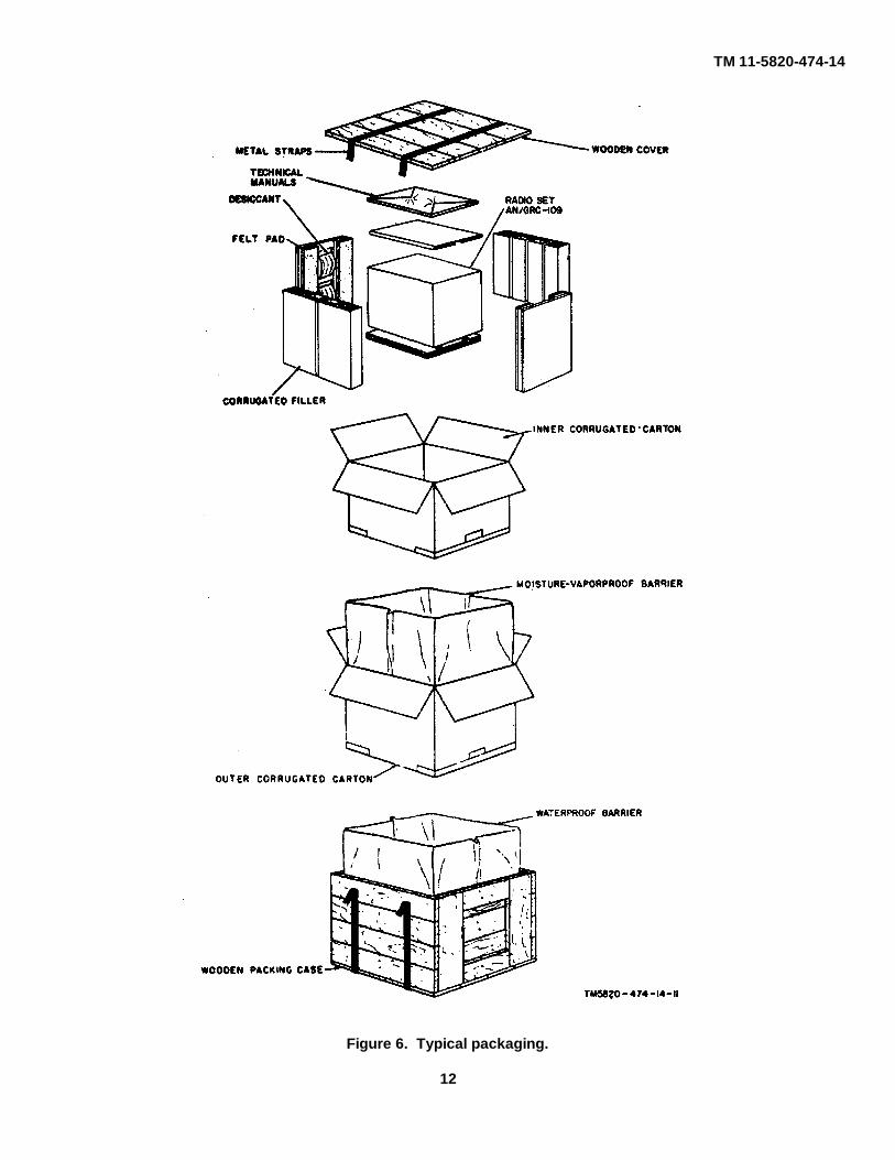
11. Unpacking(fig. 6)
a. Packing Data. When packed for shipment, eachof the four major components of the radio set is sealedin two corrugated cardboard cartons consisting of aninner carton with cardboard fillers, and an outer carton.
For certain types of shipments, the four doubly boxedunits are packed in a sealed, wooden packing casebound with metal straps; the spare parts andaccessories are. packed in. a separate wooden packingcase.
Carton No. Height (in.) Width (in.) Depth.(in.)) Volume (cu ft) Unit Weight (lb Contents of box1 of 5 9-1/4 6-1/4 6 0.2 11 Transmitter2 of 5 9-.1/4 6-1/4 6 0.2 12 Receiver3 of 5 10-3/4 9-1/4 6-1/4 0.36 27 Large power supply4 of 5 9-1/4 6-1/4 6 0.2 14 Small power supply5 of 5 12-1/4 3-7/8 6-1/4 0. 17 17 Spare parts box
Total weight 81 pounds
b. Removing Contents. Perform all the proceduresoutlined below when unpacking the equipment from thewooden packing cases. When unpacking the equipmentin cartons, omit the procedures given in (1) through (4)below.
(1) Position the wooden packing case on aflat surface with the top of the caseuppermost as indicated by the lettering onthe box.
(2) Cut the metal straps that bind the woodenpacking case; use shearing snips or theshearing jaws of ordinary pliers.
(3) Pull out the nails along the four edges ofthe top cover with a nail-puller andremove the cover. Do not attempt to pryoff the cover because the equipment maybecome damaged..
(4) Remove the outer cartons from thewooden packing cases. Open any torncarton immediately ((5) below) todetermine whether the equipment isdamaged.
(5) Open the cartons by tearing away thetaped flaps and withdrawing the innerpacking box. Open the inner carton andremove the contents. Do not force sharpor pointed objects into the cartons.
12. Checking Unpacked Equipment
a. Damage. Inspect the components for externaldamage. Loosen the four captive locking screws oneach corner of the front panels of the majorcomponents. The airtight covers may have to be priedoff, particularly if they have been kept in extendedstorage. Take care not to damage the sealing gasketunder the cover. Inspect the control panels for damageto the knobs, lamps, dials, and meter faces. Refer toparagraph 2 if any damage is noted.
b. Equipment Inventory. After the cartons areopened, check for completeness against the tables ofcomponents (para 5).
13. Siting
a. Power Source. The availability and suitability ofa power source are important in the choice of anoperating site. If ac line power is to be used, makecertain that it is alternating current between 75 and 260volts, and that the frequency is between 40 and 400cycles.
Caution: Operation from 25-cycle ordirect-current-lines will damage theequipment. The characteristics ofthe ac source can often bedetermined by an examination of theelectrical appliances that arepowered by the intended ac source.Normally,
11
TM 11-5820-474-14
Figure 6. Typical packaging.
12

TM 11-5820-474-14
electrical appliances carry amanufacturer's rating on a label,which specifies the operating voltageand frequency. If possible, verify thecharacteristics of the ac power bymaking inquiries of local personnel.
b. Antenna Location. When locating the iantenna, consider the following:
(1) Radio signals are absorbed andsometimes reflected by adjacentobstructions, such as hills, metalbuildings, and bridges; or by telephonelines that extend above the height of theantenna. Transmitted and receivedsignals have a greater range when theantenna is as high a b o v e level groundor bodies of water as possible.
(2) If transmission and reception in alldirections are desired, locate the antennaon the highest hill in the area.
(3) When operating in rear areas, keep theequipment as far as possible from sourcesof interference, such as power ortelephone lines, radar equipment, andfield hospitals.
(4) Jamming action against the receiver isalways a possibility. The effects ofjamming may be reduced by locating theantenna so that nearby obstructions act asa screen in the direction of probable sitesof jamming transmitters. This screeningaction may also reduce the transmittedsignal strength in the direction of thejamming transmitter, thereby makinginterception of signals more difficult.
14. Installation of Radio Set AN/GRC-109
a. Positioning of Equipment at Operating Site. Thepositioning of equipment at the operating site dependsupon three major considerations: available power,antenna location, and equipment location.
(1) Available power source. If no ac power isavailable, operation from a storagebattery or hand-cranked generator isnecessary. if the correct ac power is
available, either of the two power suppliesmay be /I used.
(2) Antenna location. Antenna. location isoften a primary determining factor whenpositioning the equipment at the operatingsite. Therefore, before the antenna iserected, determine which end of it is to beconnected to the radio set.
(3) Equipment location. Position the receiver,the transmitter, and the power supply on aflat, stable, and dry surface, preferably atable, box, or shelf of convenient heightthat permits operation over long periodsof time without operator fatigue.
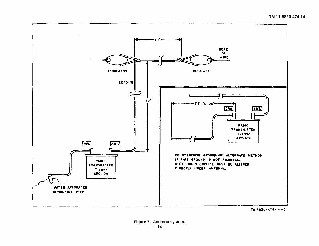
b. Erection of Antenna. To provide reliablecommunication over maximum distances, an efficientand correctly installed antenna is essential. Theantenna system supplied consists of a 100-foot coil ofbare antenna wire, two coils of rubber covered wire (100feet and 25 feet in length), insulators, and a groundclamp. To erect the antenna, proceed as follows:
(1) Install a long-wire, inverted antenna (fig.7); use the 100-foot length of antennawire and the insulators. If possible, makethe horizontal portion of the antenna 60 to70 feet long, and the vertical portion 30 to40 feet long. If the suggested horizontaland vertical dimensions cannot befollowed, use any combination ofhorizontal and vertical lengths with thetotal length at least 100 feet, and thehorizontal portions as high as possible.
(2) If the antenna length cannot be made tototal 100 feet, operation is possible withshorter lengths, depending on theoperating frequency. Use the followingchart to determine the minimum antennalengths for various operating frequencies.
Frequency (mc) Total minimum length (ft)3 to 5 755 to 7 507 to 9 35
9 to 22 25
13
TM 11-5820-474-14
Figure 7. Antenna system.14
TM 11-5820-474-14
(3) If difficulty is experienced in loading aparticular antenna, lengthen or shortenthe antenna about 10 percent.
c. Ground System (fig. 7). The efficiency of theantenna system is largely determined by the quality ofthe ground system. A good ground' is essential when astorage battery or hand-cranked generator is used topower the radio set, and highly desirable when operatingfrom an ac power source. Described below are twoground systems: pipe grounding, and counterpoisegrounding.
(1) Pipe grounding. Use this method ofgrounding if possible. The wire betweenthe GND post on the transmitter and theconnection to ground (soil) must be asshort as possible. To obtain a goodground, connect the g r o u n d wire to acold-water pipe with the ground clamp. Ifno cold-water pipe is available, drive apipe 4 to 6 feet into the soil, and thenconnect the ground clamp and groundwire to the pipe. Keep soil about the pipesaturated with water.
(2) Counterpoise grounding. If conditions atthe operating site prohibit p i p egrounding, a counterpoise must beinstalled. A counterpoise consists of oneor more extended lengths of wire, 75 to100 feet in length, connected to the GNDbinding post on the transmitter and placedon the surface of the ground d i r e (i t 1 ybeneath the horizontal portion of theantenna.
d. Preliminary Connections, Common AntennaSystem (fig. 8 and 9).
(1) Connect the H-65/U to the PHONESbinding posts (fig. 9) on the receiver.
(2) Connect the antenna lead-in to the ANTbinding post (fig. 8) on the transmitter.
(3) Connect a length of rubber-covered wirebetween the ANT bindingpost on thereceiver (fig. 9) and the RCVR ANTbinding post (fig. 8) on the transmitter.Keep this connection as short as possible.
(4) Connect a wire between the GRD bindingpost on the receiver and the RCVR GND.binding post on the transmitter. Keep thisconnection as short as possible.
(5) Connect the ground system to the GNDbinding post on the transmitter.
e. Preliminary Connections, Separate Transmittingand Receiving Antennas (fig.8 and 9). Separatetransmitting and receiving antennas may prove to bemore effective under poor transmission conditions,particularly at lower frequencies.. Separate transmittingand receiving antennas are recommended when usingan external high-speed keyer.
(1) Connect the headset to the PHONESbinding posts (fig. 9) on the receiver.
(2) Connect one lead-in to the ANT bindingpost (fig. 8) on the transmitter.
(3) Connect the other antenna lead-in to theANT binding post (fig. 9) on the receiver.
(4) Connect the RCVR GND binding post (fig.8) on the transmitter to the GND bindingpost on the receiver with a short wire.
(5) Connect the ground system to the GNDbinding post on the transmitter.
(6) Connect the REC ANT bindingpost andthe REC GND binding post on thetransmitter with a short wire.
15. Unit Interconnections, Primary Power Options
This paragraph contains instructions for connecting thetransmitter and the receiver to the optional powersources.
CautionDo not make connections to primarypower sources until all units areinterconnected.
NoteWhen not using the hand-crankedgenerator, be sure that the cover is inplace on the HAND GEN INPUTreceptacle on the large power supply(fig. 10).
a. Ac Line Operation.(1) Plug the transmitter interconnecting cable
into the TRANS. PWR. receptacle on thelarge or s m all power supply (fig. 10 and11).
15

TM 11-5820-474-14
(2) lug the receiver interconnecting cable intothe RCVR PWR. receptacle on the largeor small power supply.
(3) Turn the power selector switch on thepower supply to OFF.
(4) Connect the power supply power cord tothe ac source.
b. 6-Volt Storage Battery Operation.(1) Plug the transmitter interconnecting cable
into the TRANS. PWR. receptacle on thelarge power supply (fig. 10).
(2) Plug the receiver interconnecting cableinto the RCVR PWR. receptacle on thelarge power supply.
(4) Turn the CHARGE-OPERATE switch toOPERATE.
(5) Connect the red battery lead to thepositive terminal of the battery.
(6) Connect the black battery lead to thenegative terminal of the battery.
c. Hand--Cranked Generator Operation with LargePower Supply.
(1) Connect the transmitter interconnectingcable to the TRANS. PWR.receptacle on the large power supply (fig.10).
(2) Connect the receiver interconnectingcable to the RCVR PWR.receptacle on the large power supply.
(3) Connect the hand-cranked generator tothe HAND GEN. INPUT receptacle on thepower supply with.the 7-foot power cable.
(4) Turn the power selector switch to OFF.d. Hand-Cranked Generator 'Operation with VoltageRegulator.
(1) Connect the transmitter interconnectingcable .to the proper receptacle on thevoltage regulator.
(2) Connect the receiver interconnectingcable to the proper receptacle on thevoltage regulator,
(3) Connect the interconnecting cable on thevoltage regulator to the receptacle on thehand-cranked generator.
16

TM 11-5820-474-14
CHAPTER 3
OPERATING INSTRUCTIONS
Section I. OPERATING CONTROLS AND INDICATORS
16. Damage from Improper Settings(fig. 10 and 11)
Take the following precautions when setting the powersupply controls:
a. Before connecting either power supply to the acsource, be sure that the power selector switch is in theOFF position.
b. If the A.C. VOLTS meter indicates a voltagevalue that is between markings on the power selectorswitch, always use the higher numbered switch setting.Example: If the A.C. VOLTS meter reads 120 volts,turn the power selector switch to the 130 position.Never advance the power selector switch to a settinglower in numerical value than the A.C. VOLTS meterindication. If the switch is set to a value lower than thevoltmeter indication, the 2-ampere fuse will blow.
c. Do not turn the CHARGE-OPERATE switch onthe large power supply to the CHARGE position whenoperating from a 6-volt storage battery. To charge abattery, the power must be available from the ac source.The transmitter and receiver cannot be operated withthe large power supply during charging. For charging,turn the power selector switch to the proper position asindicated on the A.C. VOLTS meter, connect the battery
leads to the proper terminals on the battery, and turn theCHARGE-OPERATE switch to the CHARGE position.
17. Controls and Indicators
a. Radio Transmitter T-784/GRC-109 (fig. 8).Note: Numbers in parenthesis beloware circled on the panel.
Control or indicator FunctionBand switch (1) ............. Selects frequency bandExciter tuning control (2) Tunes exciter plate circuitPower amplifier tuning Tunes power amplifiercontrol (3)- plate circuit.TUNE control (4) ........... Tunes antenna circuitPower amplifier lamp ..... Indicates tuning of power
amplifier.Exciter lamp .................. Indicates tuning of exciter
stage.Antenna lamp ................ Indicates tuning of antennaTelegraph key ............... Keys transmitter for cw
operation.
Figure 8. Radio transmitter, t-184/GRC-109, front panel.
17

TM 11-5820-474-14
b. Radio Receiver R-1004/GRC-109 (fig. 9).
Control or indicator FunctionTUNING control ............ Tunes receiverRANGE switch Selects frequency bandBEAT OSC control ......... Varies pitch of received
signal. for cw receptionGAIN-BAT OFF control . Adjusts audio level in
headset, turns receiver onand off
Frequency dial .............. Indicates received signalfrequency
c. Power Supply PP-2685/GRC-109 (fig. 10).
Control or indicator FunctionPower selector switch..... Connects circuit for ac
source voltage available;connects circuit for
Control or indicator Functionbattery or had-crankedgenerator operation; turnspower supply off.
A. C. VOLTS meter Indicates ac source voltage.CHARGE-OPERATE Permits battery operationswitch. of set in OPERATE posi-
tion; charge battery inCHARGE position whenpower supply is connectedto ac source.
d. Power Supply PP-2685/GRC-109 (fig. 11).
Control or indicator FunctionPower selector switch Connects circuit for ac
source voltage available;turns power supply off.
A. C. VOLTS meter Indicates ac source voltage.
Figure 9. Radio Receiver R-100/GRC-109, front panel
18

TM 11-5820-474-14
Figure 10. Power Supply PP-2684/GRC-109, front panel.
19
TM 11-5820-474-14
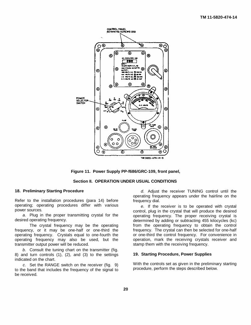
Figure 11. Power Supply PP-f686/GRC-109, front panel,
Section II. OPERATION UNDER USUAL CONDITIONS
18. Preliminary Starting Procedure
Refer to the installation procedures (para 14) beforeoperating; operating procedures differ with variouspower sources.
a. Plug in the proper transmitting crystal for thedesired operating frequency.
The crystal frequency may be the operatingfrequency, or it may be one-half or one-third theoperating frequency. Crystals equal to one-fourth theoperating frequency may also be used, but thetransmitter output power will be reduced.
b. Consult the tuning chart on the transmitter (fig.8) and turn controls (1), (2), and (3) to the settingsindicated on the chart.
c. Set the RANGE switch on the receiver (fig. 9)to the band that includes the frequency of the signal tobe received.
d. Adjust the receiver TUNING control until theoperating frequency appears under the hairline on thefrequency dial.
e. If the receiver is to be operated with crystalcontrol, plug in the crystal that will produce the desiredoperating frequency. The proper receiving crystal isdetermined by adding or subtracting 455 kilocycles (kc)from the operating frequency to obtain the controlfrequency. The crystal can then be selected for one-halfor one-third the control frequency. For convenience inoperation, mark the receiving crystals receiver andstamp them with the receiving frequency.
19. Starting Procedure, Power Supplies
With the controls set as given in the preliminary startingprocedure, perform the steps described below.
20

TM 11-5820-474-14
NoteIf an abnormal indication is obtainedduring the starting or tuningprocedure, refer to the operationalchecklist (para 33) for the correctivemeasures.
a. For operation from an ac source,; observe theindication on the A.C. VOLTS meter, and then advancethe power selector switch on the power supply (fig. 10or 11) to the setting that corresponds to the voltmeterindication. If the voltmeter indicates a value betweenswitch settings, set the switch at the higher numbericalswitch position.
b. For operation 'from a 6-volt storage battery, turnthe CHARGE-OPERATE switch on the large powersupply to the OPERATE position. Turn the powerselector switch to the BAT. position.
c. For hand-cranked generator operation with thelarge power supply, leave the power selector switch inthe OFF position.
d. Allow several minutes for the equipment towarm up.
20. Starting and Tuning Procedure, RadioTransmitter T-784/GRC-109(fig. 8)
a. Depress the telegraph key.b. Adjust control (2) for maximum brightness on
the exciter lamp. If maximum brightness is obtained atmore than one setting of the control, turn the control tothe nearest figure indicated on the tuning chart.
c. Adjust control (3) for maximum brightness onthe power amplifier lamp. If maximum brightness isobtained at more than one location of the control, adjustthe control to the nearest figure indicated in the tuningchart.
d. Adjust control (4) slowly, first to the left then tothe right; at the same time, readjust control (3) to obtainmaximum brightness of the antenna lamp. Maximumbrightness of the antenna lamp is subject to widevariation, depending on the antenna length and theoperating frequency. If the 1/2 illumination of theantenna lamp is perceptible, make the initial antennaadjustment by turning control (4) for maximumbrightness of the power amplifier lamp. Adjust 1/2control (3) to give maximum brightness of the power
amplifier lamp each time. control (4) is adjusted.Continue this procedure, alternately adjusting controls(3) and (4) for maximum brightness of the poweramplifier lamp, until a perceptable glow observed in theantenna lamp; then adjust controls (3) and (4) formaximum brightness of the antenna lamp.
e. When further adjustment of controls (3) and (4)does not yield an increase in antenna lamp brightness,adjust control (2) very slightly for maximum brightnessof the antenna lamp. This final adjustment of control (2)is very important, especially if the crystal being used isone-fourth the operating frequency.
f. Release the telegraph key; the transmitter isnow tuned.
21. Starting -and Tuning Procedure, Radio ReceiverR-1004/GRC-109
(fig. 9)
a. Advance the GAIN control clockwise until arushing (hissing) sound is heard in the headphones.
b. If both the receiver and the transmitter areoperated on the same frequency, use the transmittersignal to tune the receiver. Under these conditions,depress the telegraph key on the transmitter and slowlyrock the receiver tuning dial above and below theapproximate frequency setting until a squeal is heard.Release the telegraph key; the squeal should stop at thesame instant. If the squeal does not stop when thetelegraph key is released, the receiver is not tuned tothe transmitter frequency. Depress the telegraph keyand continue to slowly turn the tuning dial; check eachtime a squeal is heard by releasing the telegraph keyuntil the receiver is tuned to the transmitter frequency.
22. Operating Procedures
For operating convenience, a logging scale and avernier scale (fig. 9) are provided on the receiver.These scales can be used to accurately record thefrequency of a received signal for future reference..Note that 10 units on the vernier scale correspond toone unit on the logging scale.
a. Continuous-Wave Reception. Start
21

TM 11-5820-474-14
the equipment as instructed in paragraphs 18, 19, and21.
(1) Rotate the TUNING dial to tune in thesignal.
(2) Adjust the GAIN control for the desiredsound level in the headset.
(3) Adjust the BEAT OSC control until thereceived signal has the desired pitch.
b. Amplitude-Modulated (AM.) Reception. Startthe equipment as instructed in paragraphs 18, 19, and21.
(1) Turn. the BEAT OSC control to OFF.(2) Rotate the TUNING control to tune in the
signal.(3) Adjust the GAIN control for the desired
sound level in the headset.c. Transmission. Start the equipment as instructed
in paragraphs 18, 19, and 20.(1) Telegraph key. After the transmitter has
been tuned (para 20), transmit byoperating the telegraph key.
(2) External telegraph key. If operation isdesired with an external telegraph key,connect the leads from the external key tothe binding posts marked EXT. KEY andGND.
NoteThe front-panel key and the externalkey are now connected in parallel;the front-panel key is still operative.
(3) High-speed keyer. To operate with ahigh-speed keyer, remove the dummyplug from the connector marked KEYER,and plug the highspeed keyer into theconnector.
23. Operating Precaution
Overheating may occur if the radio set is operated ininclosed space without adequate ventilation. Always try.to provide ventilation when operating the equipment.
24. Recognition and Identification of Jamming
The receiver may be jammed purposely or accidentallyby other stations in the area. Jamming is accomplishedby the transmission of a strong signal on the samefrequency, which makes it difficult or impossible to hearthe desired signal. Unusual noises or stronginterference heard on the receiver may be caused byintentional jamming, noise from a local source, or adefective receiver. To determine whether theinterference is originating in the receiver, disconnect theantenna and short the ANT post to the chassis.. If theinterference continues, the receiver is defective.Jamming signals may be classified as cw or modulated.A jamming signal may be intended to block a singlefrequency; this method is called spot jamming. One ormore transmitters may be used to jam a band offrequencies; this method is called barrage jamming.
25. Antijamming
When it is known that a receiver is being jammed, theoperator will notify his superior officer immediately andcontinue to operate the equipment. To providemaximum intelligibility of jammed signals, follow theoperational procedure: below:
a. Adjust and operate the receiver as outlined inparagraphs 21 and 22.
b. Vary the TUNING dial several vernier units oneach side of the desired signal.
This may cause some separation of the desiredsignal and the jamming signal.
c. Vary the GAIN control setting. This may reducethe jamming signal enough to permit the weaker desiredsignal to be heard.
d. If the above procedures do not provide sufficientsignal separation for operation, change. .to an alternatefrequency and alternate call sign.
26. Stopping Procedure
a. When operating with the large or small powersupply, shut down the entire radio set by turning thepower supply power selector switch (figs. 10 and 11) tothe OFF position.
b. To remove the power from the receiver only,rotate the receiver GAIN control (fig. 9)counterclockwise to the BAT. OFF position.
22

C4, TM 11-5820-474-14
Section III. OPERATION UNDER UNUSUAL CONDITIONS
27. Operation at Low Temperatures
a. Do not operate the. radio at temperatures below-15°C (+5oF). At temperatures lower than -15°C,operate the radio in a heated shelter where thetemperature is maintained within the operating limits ofthe set.
b. Protect the equipment from freezing rain, sleet,and snow during both operation and storage.
28. Operating Under Tropical Conditions
The radio set may be operated in tropical, swampyareas where extreme moisture conditions exist. Try 'tokeep the equipment dry, and use silica gel or anotherdesiccant to help keep the equipment dry when it isstored.
29. Operation in Desert Climate
Do not operate the radio set at temperatures higher'than 55°C (+131oF). In temperatures higher than+55°C, the equipment must be operated in a coolshelter.
23/(24 BLANK)
C4, TM 11-5820-474-14
CHAPTER 4
OPERATOR'S MAINTENANCE
30. Scope of Operator's Maintenance
The maintenance duties assigned to the operator ofRadio Set AN/GERC109 are listed below with referenceparagraphs covering the specific maintenance functions.
a. Daily preventive maintenance checks andservices (para 31.2).
b. Cleaning (para 34.1).c. Operational checks, (para 33).d. Recharging desiccator (para 34).e. Replacement of fuses, tubes, vibrator, and
antenna lamp (para 34).
31. Preventive Maintenance
Preventive maintenance is the systematic care,servicing and inspection of. equipment to prevent theoccurrence of trouble, to reduce downtime, and toassure that the equipment is serviceable.
a. Systematic Care. The procedures given inparagraph 31.1 and 31.2 cover routine systematic careand cleaning essential to proper upkeep and operationof the equipment.
b. Preventive Maintenance Checks and Services.The preventive maintenance checks and services chart(par. 31.2) outlines functions to be performed at specific
intervals. These checks and services are to maintainArmy electronic equipment in a combat serviceablecondition; that is, in good general (physical) conditionand in good operating condition. To assist operators inmaintaining combat serviceability, the chart indicateswhat to check, how to check, -and what the normalconditions are. The References column' lists theillustrations, paragraphs, or manuals that containdetailed repair or replacement procedures. If the defectcannot be remedied by the operator, higher echelonmaintenance or repair is required. Records and reportsof these checks and services must be made inaccordance with the requirements set forth in TM38-750.
31.1. Preventive Maintenance Checks and ServicesPeriods
Paragraph 31.2 specifies check and services that mustbe accomplished daily and under special conditionslisted below in transportable and mobile installation
a. When the equipment is initially installed.b. When the equipment is reinstalled after removal
for any reason.c. At least once each week if the equipment is
maintained in a standby condition.
24.1

C4, TM 11-5820-474-14
31.2. Daily Preventive Maintenance Checks and Services Chart
SequenceNo.
Item Procedure References
1 Completeness Check for completeness of the radio set. App III.2 Publications See that all publications are complete,
serviceable,DA Pan 310.
and current.3 Cleanliness See that the equipment is clean. Para 34.1.4 Cables and connectors Inspect cables and connectors for cracks and
break.Figs 2 and 8.
5 Desiccator crystals Check desiccator crystals for a change from blueto
Para 34b.
pink.6 Fuse caps, lamps Check fuse caps and lamps for looseness.7 Battery cable clips Check battery cable clips for corrosion.8 Telegraph keys Check telegraph keys for corrosion and loose
adjust Fig. 8.ments.
9 Insulators Check insulators for dirt and moisture. Fig. 7.10 Glass Check meter glass and frequency-indicator glass
forFigs. 9 and 10.
breaks and cracks.11 Antenna wire Check antenna wire for corrosion, proper length,
and Fig. 8.. breaks
12 Controls While making the operational test (item 13),check Fig. 9.
. he action of each control for binding or scraping13 Operational test Check the radio set for normal operation. Para 38.
32. Visual Inspectiona. When the equipment fails to operate properly, turn off the power and check. all the items listed below.
WarningDo not check any item with the power on.
(1) Wrong settings of controls and switches (para 17).
24.2

TM 11-5820-474-14
(2) Poor connections of cables, headset cord,or antenna lead-in wire.
(3) Disconnected cables, plugs, or headsetcord.
(4) Grounded or broken antenna or antennalead-in wire.
(5) Bad ground connection (para 14).(6) Burned-out fuses. (This usually indicates
some other fault.)(7) Low battery voltage.
b. If the above checks do not locate the trouble,proceed to the operational checklist (para 33).
33. Operational Checklist
a. General. The operational checklist assists theoperator in quickly locating the source of trouble. Thecorrective measures are used to repair the trouble.If the measures suggested do not restore normalequipment performance, troubleshooting is required at ahigher echelon.
Note on the repair tag what corrective measureswere taken and how the equipment performed at thetime of failure.
b. Procedure. Place the set operation (para 18-21). After the equipment warms up, perform theprocedures in c below in the order given. Observe theequipment operation and perform any necessarycorrective measures.
c. Operational Checklist.
Action Normal indication Corrective measure1. Connect large or small power supply Ac voltage from 75 to 260 volts. Check 2 AMP FUSE in large powerac cord to ac source. supply.
Check FUSE in small power supply.Check to see that A. C. VOLTSmeter movement is not binding orstuck.
2. On large power supply, turn Operation of transmitter and re- Check 15 AMP FUSE.CHARGE-OPERATE switch to ceiver. Check to see that vibrator hums.OPERATE for operation from 6-volt Replace if necessary.battery; turn power selector switch Check interconnecting power cablesto BAT. and receptacles.
Check battery for proper voltageand condition of electrolyte.
3. On large power supply, turn power Operation of transmitter and Check interconnecting power cablesselector switch to OFF for opera- receiver. and connector- receptacle combi-tion from hand-cranked generator; nations.connect generator power cable toproper receptacle on unit; crankgenerator.4. Depress telegraph key and adjust Maximum brightness of lamp Check transmitter crystal by sub-control (2) for maximum brilliance situation. Replace oscillator tube,of exciter lamp (para 20b). V1, 6AC7 (para 34e).5. Depress telegraph key and adjust Maximum brightness of power Replace power amplifier tube V2,control (3) for maximum brilliance amplifier lamp. 2E26 (para 34).of power amplifier lamp (para 20c).6. Depress telegraph key and adjust Maximum brightness of antenna Check antenna system for shortscontrols (4) and (3) (para 20d and lamp and power amplifier lamps. and improper connections.e). Replace antenna lamp (para 34).
Replace power amplifier tube V2,2E26 (para 34).
7. Monitor receiver while advancing Rushing (hissing) sound in head- Check PHONES connections.GAIN control toward MAX. set. Check headset.
Check power source, interconnect-ing cables, and connector-recep-tacle combinations.By substitution, check receivertubes V1, IT4; V2, 1L6; V3,IT4; VS, IU5 (para 34f).
8. Tune receiver to transmitter fre- Tone appears and disappears as Check transmitter crystal by subquency, turn on BEAT OSC control, telegraph key is depressed and situation. Check transmitterdepress telegraph key, and moni- released, power source, telegraph key con-tor signal. tacts, interconnecting cables,
and connector-receptacle combi-nations.,Check transmitter and receiverantennas.
25

TM 11-5820-474-14
Action Normal indication Corrective measure-9. Adjust BEAT OSC control during Pitch varies with BEAT OSC Check to see that BEAT OSC con-cw reception. control rotation. trol is tight on shaft.
Replace BFO tube, V6, IT4 (para 34).
34. Repairs and Adjustments
a. Replacement of Fuses. On the large powersupply, the ac line fuse is marked 2 AMP FUSE and thebattery supply fuse is marked 15 AMP FUSE. On thesmall power supply, the ac line fuse is only markedFUSE (rated at 2 amperes). The replacementprocedure is identical for all three fuses.
(1) Rotate the knurled fusecapcounterclockwise until it is disengagedfrom the holder, and extract the fuse fromthe fuseholder.
(2) Push the fuse gasket against thefuseholder body.
(3) Withdraw the fuse from the recession inthe fusecap.
(4) Insert a new fuse of proper value into thefusecap.
(5) Replace the fuse and cap in thefuseholder, and rotate 'the cap clockwiseuntil it is tight.
b. Recharging of Desiccator Cartridges.(1) Rotate the knurled knob on the desiccator
window cover counterclockwise until it isloose from the case.
(2) Withdraw the brass desiccator cartridgeand plug the access hole tightly with a softclean cloth.
(3) Unscrew the screened brass cover cap onthe opposite end of the desiccatorcartridge and pour the desiccant into aclean metallic container. Do not heat thedesiccator cartridge.
(4) Heat the desiccant in a stove, oven,furnace, or fire until it is blue.
(5) Allow the desiccant to cool until a fewgrains can be held between the fingers fora short time without causing pain.
(6) Pour the warm desiccant into the brassdesiccator cartridge and replace thescreened brass cover cap by rotating itclockwise until it is tight.
(7) Replace the desiccator cartridge tightly inthe case by turning the cartridgeclockwise.
c. Replacement of Vibrator in Large Power Supply(fig. 36).
(1) Use the Phillips screwdriver to turn allcontrol panel retaining screwscounterclockwise until they are loose, andthen remove them.
CautionBe careful not to damage the rubbersealing gasket during the followingprocedure.
(2) Withdraw the power supply from the caseand place the control panel down.
(3) Remove the 16 screws from the sides ofthe chassis and remove the bottom coverplate.
(4) Insert a screwdriver blade between thebottom of vibrator G1 and the i vibratorsocket.
(5) With one hand, use the screwdriver to prythe vibrator from its socket; with the otherhand, rock the vibrator out of its socket.
(6) Orient the socket pins of the replacementvibrator so that the two largest pins fit intosocket pins 1 and. 6 (nearest the upperright, corner of the vibrator socketsupporting bracket) and press the 'vibratorfirmly into place.
(7) Replace the bottom cover plate and the16 screws.
(8) Replace the power supply into its case.(9) Replace all panel retaining screws and
tighten them firmly with a Phillipsscrewdriver.
d. Replacement of Power Supply Tubes.(1) Remove the case and bottom cover plate
from the large power supply, as describedin c above, and place the control paneldown.
Next printed page is 29.
26

TM 11-5820-474-14C4
(2) Remove voltage regulator tube V1, OB2,located next to the desiccator cartridge(fig. 11), by grasping and pulling it with aslight rocking motion to held ease the tubeout.
WarningThe OB2 tube contains radioactivematerial. Handle carefully to avoidbreakage (Cobalt 60 isotope, 0.0067microcuries.
(3) In the small power supply the voltageregulator tube can be removed withouttaking the unit out of its case.
(4) Use the open-end wrench supplied, andcarefully turn the VR TUBE OB2 (fig. 11)cover cap counterclockwise until it isloose enough to turn by hand. Loosenand remove it.
(5) Firmly grasp the short exposed portion ofthe OB2 with a dry finger-thumbcombination and simultaneously rock andpull the tube out of its socket.
(6) Carefully align the replacement OB2 pinswith the socket holes and press the tubefirmly into place.
(7) Cover the replacement OB2 with OB2cover cap, press it down to engage thethreads between the control panel and thecover cap, and carefully turn the covercap clockwise until it is handtight. Tightenit snugly with the open-end wrench.
e. Replacement of Transmitter Tubes (fig. 30).(1) Remove the 20 control panel retaining
screws by rotating them counterclockwisewith the Phillips screwdriver supplied.
(2) Remove the desiccator cartridge.(3) Carefully withdraw the chassis from the
case and place the control panel down.(4) To remove oscillator tube V1 (type 6AC7,
metal tube) loosen the tube retaining bandaround the base of the tube with ascrewdriver blade. Turn the locking screwcounterclockwise and remove the screw.
(5) Insert the screwdriver blade between thetube base and the socket.
(6) Carefully pry the tube from its socket androll the tube out of the chassis.
(7) Align the replacement tube pins with thesocket holes.
(8) Press the tube into the socket with firmpressure and seat the tube 'against thesocket securely.
(9) Insert the locking screw into the hole ofthe tube-retaining band; then turn thelocking screw clockwise with ascrewdriver.
(10) Tighten the locking screw, in the lockingnut, to secure the retaining band aroundthe tube.
(11) Removal and replacement of poweramplifier tube (type 2E26 glass tube withcap on top) is the same procedure as thatused for the exciter tube ((1)-(9) above)except, the plate connector on top of tubetype 2E26 must be removed andreplaced. Rotate control (3) to zero forsufficient space to remove the plate capconnector.
(12) Replace the transmitter in the case; besure that the desiccator cartridge is at thetop of the case.
(13) Replace and tighten the control panelretaining screws with the Phillipsscrewdriver.
(14) Replace the desiccator cartridge.f. Replacement of Receiver Tubes (fig. 19).
(1) Remove the desiccator cartridge.(2) Remove the 20 control panel screws with
the Phillips screwdriver.(3) Carefully withdraw the chassis from the
case.(4) Press down on the tube shield and, at the
same time, twist counterclockwise.(5) Pull the tube shield up and off the tube.(6) Grasp the tube firmly. Pull and gently
rock the tube to remove it from thesocket.
(7) Insert the replacement tube by orientingthe blank pin space on the tube, with theblank space in the socket. are aligned withthe pins in the socket, before exertingforce to seat the tube in the socket. Thisis very important because the pins on theminiature tubes are easily, bent.
29

TM 11-5820-474-14C4
(9) If the receiver remains inoperative,remove the new tube and put. back theoriginal tube. Repeat this procedure witheach suspected tube until the defectivetube is located.
(10) Replace the tube shield by pushing downagainst the spring tension and turning thetube shield clockwise.
(11) Replace the receiver in the case; be surethat the desiccator cartridge hole is at thetop of the case.
(12) Replace and tighten the control panelretaining screws.
(13) Replace the desiccator cartridge.g. Replacement of Transmitter Antenna Lamp (fig.
8).(1) Remove the antenna lamp plastic cover
by turning it counterclockwise with thefingers.
(2) ]Remove the lamp by turning itcounterclockwise until it springs out.
(3) Insert the replacement lamp by orientingthe pins on the side of the lamp with theslots in the lamp socket.
(4) Push the lamp against the tension springin the socket until the lamp, is in place.Turn the lamp clockwise to lock it inplace.
(5) Replace the lamp cover and tighten it withthe: fingers.
34.1. Cleaning.Inspect the exterior of the cases. The exterior
surfaces must be free of dust, dirt, grease, -and fungus..Warning
Cleaning Compound (FSN 7930-395-9542) is flammable and its fumes aretoxic. Provide adequate ventilation.Do not use near a flame.
a. Remove dust and dirt with a soft, clean cloth.Dampen the cloth with cleaning compound if necessary.
b. Remove grease, fungus, and ground-in dirt fromthe cases; use a cloth dampened (not wet) with cleaningcompound.
c. Remove dust and dirt from the jacks andreceptacles with a brush.
30
TM 11-5820-474-14C4
CHAPTER 5
ORGANIZATIONAL MAINTENANCE
35. Scope of Organizational MaintenanceOrganizational maintenance consists of the following:
a. Quarterly preventive maintenance checks andservices (para 38.1).
b. Troubleshooting by use of the operationalchecklist (para 33).
c. Replacing, when necessary, electron tubes,fuses, transmitter antenna lamp, large power supplyvibrator, and knobs (para 34).
36. Equipment Required for OrganizationalMaintenance
a. Multimeter AN/URM-105.b. Test Set, Electron Tube TV-7/U.c. Tool Kit, Radio Repair TK-115/G.
37. Preventive Maintenancea. Preventive maintenance is the systematic care,
inspection, and servicing of equipment to maintain it inserviceable condition, prevent breakdowns, and assureminimum operational capability. Preventivemaintenance is the responsibility of all echelons
concerned with the equipment, and includes inspection,testing, and repair or replacement of parts,subassemblies, or units that inspection and testsindicate probably would' fail before the next scheduledperiodic se vice. Preventive maintenance checks andservices of Radio Set AN/GRC-109 at the organizationallevel are made at quarterly intervals unless otherwisedirected by the Commanding Officer.
b. Maintenance forms and records to be used andmaintained in this equipment are specified in TM 38-750.
38. Quarterly MaintenanceQuarterly preventive maintenance checks and
services on Radio Set AN/GRC-109 are required.Periodic daily services (para 31.2) constitute a part (ifthe quarterly maintenance checks and services andmust be performed concurrently. All deficiencies andshortcomings will be recorded in ,accordance with therequirements of TM 38-750. Perform all checks andservices listed in the quarterly maintenance checks andservices chart (para. 37.2) in the .sequence listed.
38.1. Quarterly Preventive Maintenance Checks and Services Chart
Sequence Item Procedure ReferencesNo.1 Modifications ..................... Determine whether new applicable MWO's have TM 38-750, DA Pam
been published. All normal MWO's must be 310-4. applied immediately; all routine MWO's must be scheduled.
2 Preservation ....................... Check all surfaces for evidence of fungus. Remove TM 9-213 rust and corrosion with # 000 sandpaper and paint bare slots.
3 Switches and transformers. Inspect switches and transformers for looseness. Figs. 36, 38, and 40.4 Tubes and vibrators. Inspect tubes and vibrators for proper seating. Figs. 19, 30, and 36.5 Resistors ........................... Inspect resistors for cracks, chipping, discoloration, Figs. 21, 23, 24, 26.,
and blistering. 31, 32, 38, 41, 43, and 45
6 Capacitors ......................... Inspect capacitors for dirt, corrosion, and loose Figs. 21, 23, 24, 26, contacts. 31 through 34, 36
through :39 and 43.7 Variable capacitors Inspect variable capacitors for dirt and corrosion. Figs. 19, 21, 25, 30,
and 31.8 Dry rectifiers ...................... Inspect dry rectifiers for looseness and corrosion. Figs. 36, 42, 43, 44,
and 46
31

TM 11-5820-474-14C4
39. Troubleshooting by Using Operational Checklist
The equipment operational checklist (para 33) willhelp maintenance personnel determine whether theradio set is functioning properly. The checklist gives theitem to be checked, the normal indication of correctoperation, and the corrective measures that can betaken. If the corrective measures given d6 not fix thedefective component, troubleshooting at a higherechelon is required. Note on the repair tag how thecomponent performed.
40. Tube-Testing Techniques
Warning:The OB2 tube contains radioactivematerial. Handle carefully to avoidbreakage.
When trouble occurs, check the interconnecting powercables, the antenna connections, and the controlpositions before removing the , tubes. If tube failure issuspected, use the applicable procedure below to checkthe tubes. Refer to paragraph 34 for the instructions onremoving and replacing tubes.
a. Use of Tube Tester. Remove and test one tubeat a time. Discard a' tube only if its defect is obvious, orif the tube tester shows it to be defective. Do notdiscard a tube that tests at or near its minimum test limiton the tube tester. Reinsert the original tube beforetesting the next one.
b. Tube Substitution Method. Replace a suspectedtube with a new or good tube. If the unit remainsinoperative, remove the new tube and put back theoriginal tube. Repeat this procedure with eachsuspected tube until the defective tube is located.
32/(33 BLANK)
CHAPTER 6
THEORY
Section I. THEORY OF RADIO TRANSMITTER T-784/GRC-109
41. Relationship Between Unitsa. Common Antenna. If a common antenna is
used for transmitting and receiving, the receiver isconnected to the antenna through a network in thetransmitter. Under these conditions, the receiverantenna terminals is shorted directly to ground when thetransmitter is keyed.
b. Separate Antenna. When separate antennasare used for transmitting and receiving, the transmitterand receiver have no interrelated functions.
42. Block Diagram (fig. 14)The signal path in the transmitter is shown in the block
diagram (fig. 14) and is discussed in a and below. Forcomplete circuit details, refer to paragraphs 43 through46 and to the overall schematic diagram (fig. 64).
a. The radiofrequency (rf) signal is generated bycrystal oscillator V1. The crystal frequency may be theoperating frequency, or one-half, or one-third of theoperating frequency. Crystals equal to one-fourth theoperating frequency may also be used, but thetransmitter output power will be reduced. The necessarydoubling, tripling, or quadrupling of the crystal frequencyis accomplished in the plate circuit of V1, where thesignal is amplified and coupled to power amplifier stageV2.
b. The signal from the oscillator is amplified by V2and coupled to the antenna.The transmitter is keyed by grounding the cathodereturns of V1 and V2.
43. Oscillator (fig. 64)The oscillator stage is a combination Pierce oscillator
and a radiofrequency amplifier-multiplier. The screengrid acts as the anode for the oscillator circuit and the
signal is electron coupled to the plate circuit. A dummyplug, P2, completes certain circuits in the oscillator andpower amplifier stages when an external automatickeyer is not used. Although only one crystal is used, twocrystal sockets are provided on the front panel toaccommodate crystal holders with pins spaced eitherone-half or three-fourths of an inch.
a. Capacitor C1 blocks the direct current (dc)voltage on the screen grid from the crystal. Resistor R1develops grid leak bias (with the capacitance of thecrystal holder and C1) and returns the control grid toground. Cathode bias is developed by R2 and C2 whenthey are grounded through the keying circuit.
b. The plate and screen grid circuits are decoupledfrom the power supply by the network made up of C7,R6, and R7. Capacitor C3 returns the screen grid toground for rf, and L5 and R4 form the load for thescreen grid circuit.
c. The oscillator plate circuit is tuned by variablecapacitor C6 and coils L1 and L2. When band selectorswitch S1A is in position 1 (3-6 mc), L1 and L2, inseries, are connected across C6 through C7. With S1Ain position 2 (6-10 mc), a portion of L2 is shorted out.For operation in position 3 (10-17 mc), S1A shorts outL2, so that only L1 is connected across C6. With S1A inposition 4 (17-22 mc), the tuned circuit consists of only aportion of L1 connected across C6. Proper tuning of theoscillator is indicated when neon lamp DS1 glows withmaximum brightness when the plate circuit is tuned toresonance by C6. Resistor R3 in series with the lamplimits current through the lamp to a safe value. Theoscillator signal is coupled to the control grid of poweramplifier V2 through capacitor C8.
34

Figure 14. Radio Transmitter T-784/GRC-109, blockdiagram.
44. Power Amplifier (fig. 64)a. The power amplifier uses a 2E26 tetrode (V2) in
a conventional class C amplifier circuit. Grid leak biasis developed across grid resistor R8. Cathode bias isdeveloped across paralleled cathode resistors R9A andR9B. Radiofrequency choke L6 in series with R8presents a high impedance load to the signal from theoscillator. It prevents the loss of a large portion of thesignal to ground through the relatively small resistanceof R8. Capacitor C9 is the cathode bypass. CapacitorC11 is an rf bypass for the common oscillator-poweramplifier B+ supply. Screen grid voltage is appliedthrough paralleled voltage-dropping resistors R10 andR11. Capacitor C10 is the screen grid bypass.Paralleled resistor R12 and choke L8 are used tosuppress very-high frequency (vhf) parasitic oscillations.
b. A pi network is used for plate circuit tuning andantenna coupling and tuning. The network is composedof C12, coiled L3 or IA (depending on the band beingused), and C16. Switch S3 is ganged with C16 so thatS3 is closed when tuning low impedance (LO Z)antennas, and open when tuning high impedance (HI Z)antennas. When S3 is closed, C15 is placed in parallelwith C16 This arrangement gives a continuouslyvariable output capacity, from 20 to 380micromicrofarads (uuf), so that a wide range of antennaimpedances can be matched by the power amplifier.
c. Antenna tuning lamp DS3 glows with maximumbrightness when the antenna is properly tuned. ResistorR13 in parallel with DS3 limits the current through thelamp to a safe value. Capacitor C12 tunes the platecircuit. Neon lamp DS2 glows with maximum brightnesswhen the circuit is at resonance. There is sufficient rfpower in the plate circuit so that only one lead of DS2 isconnected for an indication of resonance. The capacityto ground of the clipped, unattached lead completes thecircuit through the lamp. Coil L3 or LA is selected byS1B and S1C, depending on the band in use. All of L4is in the circuit for band 1; only a portion is used forband 2. All of L3 is in the circuit for band 3; only aportion is used for band 4. Capacitor C13 is used tocouple the signal from the pi network to the antenna,and isolates the antenna from the B+ in the plate circuit.Radiofrequency choke L9 presents a high impedance tothe rf currents in the pinet-work to keep them out of thepower supply.
45. Receiving Antenna Circuit (fig. 64)When a common antenna is used for transmitting and
receiving, the receiver is connected to the antennathrough capacitors C4 and C14 by a jumper from thereceiver antenna binding post to J3, the RCVR ANT.post on the transmitter. The input circuit of the receiveris protected from rf power during transmission by theground through the key. Any rf voltage on C4 when thekey is down is shorted directly to ground by the rectifiercircuit composed of germanium diodes CR1 and CR2.CR1 conducts on positive voltage peaks; CR2 conductson negative peaks. When the key is up, rf choke L7, inseries with the cathode circuits of V1 and V2, preventsthe received signal from being shunted to groundthrough the low-impedance path in the cathode circuits.46. Keying (fig. 64) The transmitter is keyed bybreaking the cathode circuits of V1 and V2. Normallythis is done by the front-panel telegraph key, S2.However, an external key may be connected betweenEXT. KEY post J2 and ground. In this case, the panelkey and the external key are connected in parallel; and
35

either can be used to operate the transmitter. Anautomatic high-speed keyer can be connected to theKEYER jack, J1, after removing plug P2. Plug P2 mustbe in place to operate the transmitter manually. The
parallel combination of resistor R5 and capacitor C5, inseries with the cathode circuits of V1 and V2, is a keyclick filter.
Section II. THEORY OF RADIO RECEIVER R-1004/GRC-109
47. Block Diagram (fig. 15)a. The receiver can be used for the reception of
am. cw, and mcw signals. Fixed-frequency operation ispossible by the use of a plug-in front-panel crystal. Thesignal path is shown in the block diagram and isdiscussed in b below. For complete circuit details, seeparagraphs 48 through 53 and the overall schematicdiagram (fig. 63).
b. Signals from the antenna are applied to rfamplifier V1. The amplified output from this stage iscoupled to converter V2. The 455-kc converter output isamplified by intermediate-frequency (if.) amplifiers V3and V4. The amplified if. output is applied to detector-audio amplifier V5. The detector section of V5demodulates the if. signal, and the resulting audiosignal is amplified by the amplifier section of V5.Output from the audio amplifier is applied to thereceiver headset binding posts. Beat-frequencyoscillator (bfo) V6 supplies the rf signal necessary toproduce an audio note during the reception of cwsignals, and also generates bias voltage for V1, V3, V4,and V5. The bfo output is coupled to the detectorsection of V5.
NoteThe conditions described inparagraphs 48 and 49 are producedwith the RANGE switch in the band 1position. Operation is identical withthe RANGE switch in any of the threepositions. Only the values of thecomponents needed to tune thehigher frequencies are' changed.
48. Radiofrequency Amplifier (fig. 63)a. Rf amplifier V1 uses a 1T4 pentode operating as
a class A voltage amplifier. The signal from theantenna is fed to the primary of antenna coil L1 bysegment X of band selector switch S1A rear. CapacitorsC1 and C13, which shunt the secondary of L1, limit thehighest frequency to which the secondary will tune.Tracking at the high-frequency end of the band isaccomplished by adjusting C1; tracking at the low-frequency end is accomplished by adjusting thepowdered-iron core of L1. The secondaries of theunused antenna coils are shorted together by S1A frontto prevent interaction with the coil in use. Grid bias forV1 is fed through resistor R1 from the receiver biassupply. The gain of the stage is controlled by varyingthe bias and is dependent on the setting of receiverGAIN control R28. Capacitor C16 prevents rf or if.signals from other amplifier stages from entering thegrid circuit of V1 through the bias line.
Figure 15. Radio Receiver R-1004/GRC-109, block diagram.
36

b. The rf signal developed across the secondary ofL1 is fed to the grid of V1 through segment Y of S1Arear. The grid circuit is tuned to the signal frequency byC10, a section of the main tuning capacitor. CapacitorC17 bypasses any rf currents in the filament circuit ofV1, to ground. Screen voltage is dropped to the propervalue by R2. Capacitor C18 bypasses rf currents in thescreen voltage, to ground. Capacitor C45 is an rfbypass filter for the B+ supply.
c. The plate circuit is tuned to the incoming signalfrequency by C11. Section S1B rear connects L4 acrossC11. Tracking at the high end of the band isaccomplished by adjusting C4; tracking at the low end isadjusted by turning the powdered iron core in L4A. Theunused plate circuit coils are shorted together by S1Bfront to prevent interaction with the coil in use. ResistorR3 and capacitor C19 form a plate-decoupling network.The amplified signal is coupled to the converter throughcapacitor C20.
49. Converter (fig. 63)a. Converter V2 uses a 1L6 pentagrid tube to
produce a 455-kc output from the mixing of the inputsignal and the oscillator signal. The oscillator sectionmay be operated as a variable frequency oscillator or asa crystal-controlled oscillator for fixed-frequencyoperation.
b. The signal from V1 is applied to the signal grid(pin 6) of V2. Grid leak bias is developed acrossresistor R4. Capacitor C22 and choke L12 form a filtercircuit to prevent rf signals from entering the filamentline. Screen grid voltage is dropped to the proper valueby thermistor RT6, which helps stabilize the circuit.Capacitor C23 is the screen grid bypass. Resistor R8and capacitor C26 form a plate decoupling network.The 455-kc if. signal is inductively coupled to the first if.amplifier through T1. Capacitors C24 and C64 resonatethe primary of T1 to the if frequency; tuning adjustments
are made by turning the powdered-iron cores inside thetransformer.
c. When the oscillator section of the converter iscontinuously tunable, segments X and Y of S1C rearselect the proper oscillator coil for the band in use.Section S1C front shorts out the unused grid windings.The plate coil of L7 is an untuned tickler winding thatprovides feedback to the oscillator grid. The oscillatorplate (pin 3) receives its voltage through thermistorRT27 and the tickler winding. Capacitor C59 and RT27form a decoupling circuit. Without a crystal in crystalsocket XY1, R7 is shorted out of the circuit. The gridwinding of L7 is shunted by trimmer capacitor C7, whichis used to adjust oscillator tracking at the high end of theband. Tracking at the low end of the band isaccomplished by turning Use powdered iron cord in L7.Capacitor C12 is the main oscillator tuning capacitor.Grid leak bias for the oscillator is provided by theparalleled resistor RS-capacitor C21 combination inseries with resistor R18. Capacitor C42 is an rf bypass.
d. Placing a crystal in crystal socket XY1 convertsthe oscillator to a conventional Pierce oscillator with thecrystal connected directly between the oscillator grid(pin 4) and anode (pin 3). Capacitor C21 is removedfrom the circuit and capacitors C55 and C56 are added.Resistor R7 is placed in series with the oscillator plate Bline. Grid leak bias is developed by the combination ofC7, R18, and C42. Resistor R7 isolates the plate ticklercoils from the circuit. Capacitors C55 and C56 areadded to provide better control over oscillator excitation.
50. First If. Amplifier (fig. 63)First if. amplifier V3 uses a 1T4 pentode as a voltage
amplifier for the 455-kc signal from the converter. Thesignal is inductively coupled to the secondary of iftransformer T1. The transformer secondary is tuned toresonance by paralleled capacitors C25 and C65. Gridbias is supplied through resistor R9 from the biassupply. Capacitor C27 and R9 decouple the
37

grid circuit from the common bias line. The gain of V3is determined by the setting of GAIN control R28.Screen grid voltage is dropped to the proper value byresistor R10. Capacitor C28 is the screen grid bypass.Resistor R11 and capacitor C31 form a plate circuitdecoupling network. The amplified if. signal is fed fromthe plate of V3, to the primary of if. transformer T2.The primary of T2 is tuned to resonance by fixedcapacitors C29 and C61; tuning adjustments are madeby adjusting the powdered-iron cores in T2.
51. Second If. Amplifier (fig. 63)Second if. amplifier V4 is identical in function and
operation to the first if. amplifier. There are twophysical differences between the stages. The 10-uufpadding capacitor (C63), across the secondary of T2, ismounted outside of the transformer can. The primary ofT3 is tuned to resonance by a single capacitor, C34,rather than two capacitors.
52. Defector-Af Amplifier (fig. 63)Detector-audiofrequency (af) amplifier V5 uses a 1U5
diode-pentode to demodulate the if. signals, and toamplify the resulting audio to drive the receiver headset.The if. signal from V4 is inductively coupled lo thesecondary of T3. Capacitors C35 and C62 resonate thesecondary to 455-kc. Rectification of the if. signaltakes place at the diode (pin 4) of V5. The resultingaudio voltage is developed across diode load resistorsR15 and R16. Capacitors C37 and C38 filter out the455-kc component of the rectified signal. The audiosignal is coupled to the grid (pin 6) of the pentodesection by C39. Grid bias is supplied through resistorR17 from the junction of voltage divider resistors R21and R22 in the bias supply line. Paralleled capacitorsC41 and C58 provide filtering for the power supply, andare audio bypasses for the screen grid circuit. Theamplified[ audio signal from the plate is coupled to theheadset binding posts by output transformer T4. Thetransformer provides a 4,000-ohm output impedance atthe PHONES jacks J3 and J4. Capacitors C40 and C57
short-circuit audio frequencies above 3,000 cycles persecond (cps), because these frequencies add little to theintelligibility of voice signals, and can be the source ofnoise.
53. Beat-Frequency Oscillator (fig. 63)a. The bfo uses a triode-connected 1T4 (V6)
pentode in a Hartley oscillator circuit, to supply thesignal necessary to make cw signals audible. Theoutput of the bfo is also rectified to produce bias voltagefor V1, V3, V4, and V5. Since bias is necessary whetheram., mcw, or cw signals are being received, the bfofunctions continuously. When signals other than cw arebeing received, the bfo is tuned to a frequency highenough to make the beat note inaudible.
b. Plate voltage for V6 is obtained from the powersupply through voltage-dropping resistor R23 and thecenter tap of L10, the oscillator coil. Capacitor C49 isan rf bypass and places the center tap of L10 at rfground potential, permitting the rf voltage on the plateand grid to be in phase to sustain oscillations. Thefrequency of oscillation is determined by capacitor C50in parallel with series capacitors C51 and C52, and L10.The bfo frequency can be shifted slightly on each sideof the 455-kc if. frequency by adjusting C52 to obtainthe desired beat note. When the BEAT OSC: control isin the OFF position, the plates of C52 short together andremove the capacitor from the circuit. The bfofrequency is then sufficiently high to make the beat noteinaudible. Operating bias is developed by C54 and R25.Capacitor C54 provides a positive feedback path fromthe plate circuit to the grid circuit. Choke L11 preventsthe bfo signal from being fed into the filament line.Stray capacitances couple the bfo output to the diodesection cf V5 where mixing of the received signal andthe bfo signal takes place.
c. Germanium diode CR1 rectifies the bfo outputto provide the bias supply. Capacitor C48 blocks theplate voltage from the rectifier circuit.
38

The pulsating negative dc voltage from CR1 is filteredby resistor R24 and capacitor C47, and then is fed tovoltage-dividing circuits. Fixed bias for V5 is obtainedfrom the junction of resistors R21 and R22. A variablebias voltage for V1, V3, and V4 is obtained frompotentiometer R28, the receiver GAIN control, in series
with R26. Capacitor C46 is an rf bypass for the grid biasline. BAT. OFF switch S2, mounted on the rear of thegain control, is the receiver on-off switch. It disables thereceiver by disconnecting the filament voltage.Capacitor C53 is a. bypass filter for the filament line.
Section III THEORY OF POWER SUPPLY PP-2684/GRC-109
54. Block Diagram (fig. 16)a. Power Supply PP-2684/GRC-109 furnishes B+
and filament voltages to operate the transmitter and thereceiver. The large power supply can be operated fromeither of three primary power sources:
(1) Ac lines that furnish 75 to 260 volts, 40 to400 cycles.
(2) Six-volt storage battery.(3) Hand-cranked generator. When operated
from ac lines, the power supply can alsobe used to charge a 6-volt storagebattery. The modes of operation areshown in the block diagram and discussedin b through e below. For complete circuit
details, refer to paragraphs 55 through 58and the overall schematic diagram (fig.65).
b. When operated from ac lines, powertransformer T1 steps up the line voltage for thetransmitter and receiver B+ supplies, and steps downthe line voltage for the transmitter and receiver filamentsupplies. High voltage from the secondary of T1 isrectified by rectifiers CR1 through CR4, and is filtered toprovide 450 volts for transmitter B+. Rectifiers CR1 andCR3 of the bridge circuit also operate to provide 108volts receiver B+ after regulation by V1 and filtering.Transmitter filament voltage of 6.3 volts ac is takenfrom a separate secondary winding on T1.
Figure 16. Power Supply PP-2684/GRC-109, block diagram.
39

The rectifier filament voltage is derived from anadditional secondary winding on T1. The voltage isrectified by rectifiers CR5 and CR6, filtered, and 'thenregulated by selenium rectifier CR7. The output is 1.3volts dc.
c. When operated from a 6-volt storage battery,vibrator G1 is connected across the vibrator winding onthe primary of T1. An ac voltage appears in thesecondary. Transmitter and receiver B+ voltages arerectified, filtered, and regulated as they are when thepower supply is operated from the ac line. Transmitterfilament voltage is taken direct from the storage battery.A portion of the battery voltage is filtered, and thenregulated by CR7 to supply the receiver filaments.
d. When the power supply is operated from thehand-cranked generator, T1 is bypassed and the 450-volt dc generator output is applied at the input to therectifier circuit. The transmitter and receiver B.+voltages are treated as they are when the power supplyis operated from the ac line. The 6-volt dc generatoroutput is supplied directly to the transmitter filaments; aportion of this voltage is filtered, then regulated by CR7to supply the receiver filaments.
e. When the large power supply is used for batterycharging. CHARGE-OPERATE switch S1 must be inthe CHARGE position. The ac line voltage is steppeddown by T1 and rectified by CR5 and CR6. The dccharging voltage is applied through S1A to the positive6-volt battery terminal.
55. AcLine Operation (fig. 65)a. Ac voltage is fed to the primary of T1 through
plug P3, fuse F2, and pins 1 and 2 of the chassis-paneldisconnect combination plug P7 and jack J1. Fuse F2protects T1 if power selector switch S2 is set at a lowervalue than that of the ac line voltage. Ac voltmeter M1is connected directly across the ac line to indicate linevoltage. The meter is used to determine the propervoltage setting for S2. Capacitors C12 and C13,connected across the ac line, filter any rf interferencefrom the power source.
b. There are three primary windings on T1. One ofthe primary windings (black, blue-white and black leads)is the vibrator winding and is not used for ac operation. Proper taps, depending on the line voltage, are selectedon the two primary windings selected by S2E, S2F, andS2G. The windings are connected in series foroperation a from 150-, 180-, 220-, and 260-volt lines,and in parallel for operation from 75-, 90-, 110-, and130-volt lines. The voltage is stepped up by the high-voltage secondary and rectified by selenium rectifiersCR1, CR2, CR3, and CR4, a full-wave, bridge rectifiercircuit. The pulsating dc output from the bridge isfiltered by the series parallel combination of electrolyticcapacitors C4A, C4B, C5A, and C5B, and then fed topin 3 of the TRANS PWR. plug P4. Resistors R8 andR9 equalize the voltage distribution across theelectrolytic capacitors. Radiofrequency choke L1 isused to suppress radiofrequency interference (hash)caused by sparking at the vibrator contacts when thevibrator is in use.
c. Receiver high voltage comes from the samewinding on T1 as the transmitter high voltage. RectifiersCR1 and CR3 operate as a full-wave rectifier circuit inaddition to their function in the bridge rectifier circuit.Output voltage is taken from the center tap of the high-voltage winding. This voltage is approximately one-halfthe value of that obtained at the output of the bridgerectifier circuit. Filtering of the pulsating dc is done byelectrolytic capacitors C7A and C7B, and resistor R6.Resistors R5 and R6 are shorted out by the jumperinside the cover of HAND GEN. INPUT plug P6. Thevoltage is held at 108 volts by V1, an OB2 gas-filledvoltage-regulator tube. Resistor R7 prevents V1 fromacting as a low frequency relaxation oscillator. Rf chokeL5 is used for hash suppression. The regulated voltageis fed to pin 3 in the RCVR PWR plug P5.
d. Receiver filament voltage is derived from aseparate secondary winding on T1. To produce filamentvoltage, the ac from a winding on T1 is rectified byselenium rectifiers CR5 and CR6 in a full-wave rectifiercircuit. The rectified voltage is
40
taken from the center tap of the transformer winding andfed through S1A, voltage-dropping resistor R3, S2C,and voltage-dropping resistor R4 to the input of thefilter-regulator circuit. Filtering is accomplished byelectrolytic capacitors C8 and C9 and filter choke L2.The filtered voltage is regulated at 1.3 volts by seleniumrectifier CR7 and fed to pin 4 of RCVR PWR plug P5.
e. Transmitter filament voltage is obtained from a6.3-volt secondary winding on T1. The voltage is fedthrough S2D to pin 5 of TRANS PWR plug P4.Capacitor C11 is a hash filter that prevents rfinterference from the vibrator when used. The 6.3-voltwinding of T1 is used only when the power supply isoperated from ac lines.
56. Storage Battery Operation (fig. 65)a. When the large power supply is operated from a
6-volt storage battery, power selector switch S2 must bein the BAT. position. The battery is connected to the 6VOLT INPUT battery cables P1 and P2. Current flowsthrough fuse F1 and pin 3 of the panel-!chassisdisconnect combination J1 and P7, to S2B, S2C, andS2D. Capacitor C14 is a filter that prevents hash frombeing radiated through the positive battery cable.Battery voltage on S2B is fed through a hash filter circuitcomposed of capacitors C1 and C2 and choke L4, andthen to the center tap of the vibrator winding on T1. Thetwo primary windings used when operating from ac linesare disconnected by S2E and S2G. Vibrator G1 isconnected across the vibrator winding by S2A. Thevibrator rapidly interrupts the battery current in thevibrator winding at regular intervals. This results insquare wave dc pluses which cause an ac voltage to bedeveloped in the secondary. The induced voltage isthen rectified, filtered, and regulated as it is duringoperation from the ac lines. Resistors R1 and R2 aredamping resistors that reduce sparking at the vibratorcontacts and assist in the elimination of radiated hash.Capacitor C3 across the high-voltage secondary of T1 is
a buffer capacitor that absorbs voltage surges whichoccur when the vibrator. breaks' the primary current.When the primary current is broken, the primarymagnetic field collapses very rapidly and induces avery-high voltage in the secondary.
b. Battery voltage at S2D is fed directly to pin 5 ofTRANS PWR plug P4 for the transmitter filaments.Receiver filament voltage is taken from the batteryvoltage applied to S2C. The voltage is fed throughvoltage-dropping resistor R4 and the filter-regulatorcircuit composed of C8, L2, C9, and CR7, to pin 4 ofRCVR PWR plug P5.
57. Hand-Cranked Generator Operation (fig. 65)a. To operate the large power supply from the
hand-cranked generator, power selector switch S2 mustbe in the OFF position. This disconnects the primariesof T1, which are not used in this mode of operation.Removing the cover of the HAND GEN. INPUT plug P6disconnects the jumper across resistor R5 and placesthe generator in the circuit.
b. The 450-volt dc input from the hand crankedgenerator is fed through pin 3 of P6 to the junction of rfchoke L3 and resistor R5. Transmitter B+ is thus fed tothe center tap of the high-voltage winding of T1, andthen passes through selenium rectifiers CR2 and CR4.The rectifiers offer little resistance to the de voltage.The voltage is filtered before being fed to pin 3 of P4.
c. Receiver B+ is also obtained at the junction ofL3 and R5. Resistor R5 drops the voltage to the propervalue for the receiver. The voltage is then filtered andregulated in the same manner as when the power supplyis operated from ac lines.
d. Hand-cranked generator 6-volt dc filamentpower input is fed into pin 5 of P6, and then to S2C andS2D. The voltage on S2D is fed to pin 5 of TRANS.PWR. plug P4. The voltage on S2C is fed to voltagedropping resistor R4, and then filtered and regulated inthe same manner as when the power supply is operatedfrom ac lines.
41

58. Battery-Charging OperationWhen the large power supply is used for charging a 6-
volt storage battery, CHARGE-OPERATE switch S1must be in the CHARGE position. Power selector switchS2 must be in the correct position for the ac line voltagebeing used. The high-voltage secondary is
disconnected from the circuit by S1B and S1C. ResistorR10, a current-limiting resistor, is placed in the chargingcircuit by S1A. Selenium rectifiers CR5 and CR6 rectifythe charging current which is fed through R10 to thepositive battery cable, P2.
Section IV. THEORY OF POWER SUPPLY PP-2685/GRC-109
59. Block Diagram (fig. 17)a. Power Supply PP-2685/GRC-109 furnishes B+
and filament voltages to operate the transmitter and thereceiver. Voltages supplied to the receiver areregulated. The small power supply operates from aclines only, 75 to 260 volts, 40 to 400 cycles. Forcomplete circuit details, see paragraph 60 and theoverall schematic diagram (fig. 66).
b. Power transformer T1 steps up the line voltagefor B+ supplies, and steps, it down for filament supplies.High voltage from T1 is rectified by CR1 through CR4,and filtered to provide 450 volts for transmitter B+.Rectifiers CR1 and CR3 also operate to provide 108volts receiver B+ after filtering and regulation by V1.Transmitter filament voltage is 6.3 volts ac from T1.
Receiver filament voltage is also derived from T1. Thevoltage is rectified by rectifiers CR6 and CR7, filtered,and regulated by rectifier CR5 to provide 1.3 volts dc.
60. Circuit Analysis (fig. 66)a. Ac voltage is fed to the primary of power
transformer T1 through line cord plug P3 and fuse F1.Fuse F1 protects T1 in the event input power selectorswitch S1 is set at a lower value than that of the ac linevoltage. Ac voltmeter M1 is connected directly acrossthe ac line and indicates the line voltage. The meter isused to determine the proper voltage setting for switchS1. b. Proper taps of the two primary windings of T1are selected by S1, depending on the voltage of the acline.
Figure 17. Power Supply PP-2685/GRC-109, block diagram.
42

The windings are connected in series for operation from150-, 180-, 220-, and 260-volt lines. They areconnected in parallel by S1B for operation from 75-, 90-,110-, and 130-volt lines. The primary voltage is steppedup by the high-voltage secondary of T1 and rectified byselenium rectifiers CR1, CR2, CR3, and CR4, a full-wave bridge rectifier circuit. The pulsating dc outputfrom the bridge is filtered by a single electrolyticcapacitor, C5, and fed to pin 3 of TRANS PWR plug P1.
c. Receiver B+ comes from the same high-voltagewinding of T1 as the transmitter B+. Rectifiers CR1 andCR3 operate as a full-wave rectifier circuit, in addition totheir function in the bridge-rectifier circuit. The pulsatingdc voltage is approximately one-half the value of thatobtained from the bridge-rectifier circuit. Filtering is byelectrolytic capacitors C1 and C2, and resistor R2. Thevoltage is regulated at approximately 108 volts by V1,
and OB2 gas-filled voltage-regulator tube. Resistor R3prevents V1 from acting as a low-frequency relaxationoscillator. the regulated voltage is fed to pin 3 of PCVRPWR plug P2.
d. Transmitter filament voltage is obtained -from a6.3-volt secondary wing on T1. The voltage is feddirectly to pin 5 of TRANS PWR plug P1. Filamentvoltage for the receiver comes from a separatesecondary winding. The voltage is rectified by CR6 andCR7 in a full-wave rectifier circuit. The pulsating dc istaken from the center tap of the transformer winding andfed through voltage-dropping resistor R1 to the input ofthe filter-regulator circuit. Filtering is by electrolyticcapacitors C3 and C4, and filter choke L1. The filteredvoltage is regulated at 1.3 volts by selenium rectifierCR5 and fed to pin 4 of RCVR PWR plug P2.
43/(44 BLANK)

TM 11-5820-474-14C4
CHAPTER 7
TROUBLESHOOTING
Note:All troubleshooting procedures may be performed by third or fourth echelon personnel.
Section I. GENERAL TROUBLESHOOTING TECHNIQUES
Warnings: 1. Be extremely careful when servicing the power supplies and transmitter because voltagesabove 450 may be present. Do not contact the ac lines when connecting power supplies;voltages up to 260 may be encountered. 2, When selenium rectifiers fail because of burnout or arc-over, poisonous fumes andcompounds are released, The fumes have a strong odor and must not be inhaled. Provideadequate ventilation. Do not handle the rectifier until it has cooled.
61. General InstructionTroubleshooting at field and depot maintenance level
includes all the techniques outlined for organizationalmaintenance, and any special or additional techniquesrequired to isolate a defective part. The fieldmaintenance procedures are not complete inthemselves, but supplement the procedures described inthe organizational maintenance section of this manual.The systematic troubleshooting procedure, which beginswith the operational and sectionalization checks that canbe performed at an organizational level, must becompleted by means of localizing and isolatingtechniques.
62. Organization of Troubleshooting Proceduresa. General. The first step in servicing a defective
radio set is to sectionalize the fault. Sectionalizationmeans tracing the fault to a major component. Thesecond step is localization. Localization means tracingthe fault to a defective stage or circuit of the majorcomponent. The defective part responsible for theabnormal operation is then isolated by voltage,resistance, and continuity checks. Some faults, such asburned-out resistors, and arcing and shortedtransformers, can often be located by sight, smell, andhearing. The majority of faults, however, must beisolated by checking voltages and resistances.
b. Sectionalization. Radio Set AN/GRC-109consists of a transmitter, a receiver, and two powersupplies. Only one of the power supplies is required tooperate the receiver and transmitter. The first step in
tracing trouble is to locate the component at fault by thefollowing methods:
(1) Visual inspection. The purpose of visualinspection is to locate faults withouttesting or measuring circuits.
(2) Operational tests. Operational tests mayindicate the component at fault. In somecases, they will help to determine thespecific fault. The checklist given inparagraph 33 is an operational test.
c. Localization. The tests listed below will aid inlocalizing the trouble to a single stage or circuit of acomponent.
(1) Troubleshooting charts. Thetroubleshooting charts (para 66, 73, 79,and 83) give a systematic method oflocating malfunctioning circuits.
(2) Signal substitution. Signal substitutioncharts (para 67), when used in conjunctionwith the troubleshooting chart, provide amethod of localizing trouble to a particularstage of the receiver.
d. Isolation. The defective part is usually locatedby voltage and resistance measurements. The voltageand resistance charts (fig. t8 and 35) will aid in locatingthe defective' part in the receiver and transmitter. Takereadings and compare them with normal readings on thechart. Consult the overall schematic diagrams whentaking voltage and resistance readings in the powersupplies.
44.1/(44.2 BLANK)

TM 11-5820-474-14C4
NoteDuring these tests, the possibility ofintermittent troubles should not beoverlooked. If present, this type oftrouble often may be made toreappear by tapping thecomponents.
63. Test Equipment RequiredThe following chart lists the test equipment required
when troubleshooting Radio Set AN/GRC-109. Theassociated technical manuals and the assigned commonnames are also listed.
Test equipment Technical manual Common name
Test Set, Electron Tube TV-7/U ........................ TM 11-6625-274-12 ................... Tube testerMlultimeter 1U-26/U ........................................... TM 11 6625-200-12.................... VtvmR. F. Signal Generator AN/URM-25A ............... TM 11-5551A ............................ Rf signal generatorAudio Oscillator TS-382A/U .............................. TM 11-6625-261-12 ................... Audio oscillatorWattmeter AN/URM-120 ................................... TM 11-6625-446-15 ................... WattmeterVariable Transformer CN-16/U .......................... .................................................. Variable transformerMultimeter TS-352/U ......................................... TM 11-5527 ............................... Multimeter
Section II. TROUBLESHOOTING RADIO RECEIVER R-1004/GRC-109
CautionDo not attempt removal or replacement of parts before reading the instructions given inparagraph 87.
64. Checking Receiver Filament and B+ Circuit forShorts
a. When to Check. When either of the followingconditions applies, check for short circuits and clear thetrouble before applying power.
(1) When the receiver is being serviced apartfrom other units of Radio Set AN/GRC-109 and the nature of the abnormalsymptoms is not known.
(2) When abnormal symptoms reported fromoperational tests indicate the possibility of
a short circuit in the filament or B+circuits.
b. Conditions for Tests. To prepare for the short-circuit tests, perform the following. procedures:
(1) Remove the receiver from its case.(2) Remove all tubes.
c. Measurements. Make the resistancemeasurements indicated in the following chart. Ifabnormal readings are obtained, make the additionalisolating checks outlined. When the faulty part is found,make repairs before applying power.
Short-circuit testsPoint of measurement Normal resistance Isolating procedure
Between pins 2 and 3 of power Plug P1 Approximately 15 megohms If resistance is zero, check for (fig. 18). shorted capacitor C40, C41, C45,
or C58 (fig. 24 and 27), or for short-circuited B+ wiring.If resistance Is low. check for leak- age in one of above capacitors or other shorted capacitor in one of plate or screen grid circuits, or in C49 (fig. 21) in bfo assembly (fig. 19).
Between pins 2 and 4 of power plug P1 Infinite If resistance is zero, check for (fig. 18). shorted capacitor C17, C22, or
C53 (fig. 24 and 27), or for short-circuited filament wiring.
45

TM 11-5820-474-14
65. Test Setup (fig. 18)a. Bench tests of the receiver require connection
to a power source and to various test equipments. Thepower source must be connected to the receiver for alldynamic servicing procedures. The test equipmentconnections vary from test to test.
b. Either the large or small power supply is themost convenient power source for use : in receiverbench tests. If either is available, connect the receiverpower cable to the RCVR PWR jack on the powersupply. If one of these is not available, use a powersource capable of supplying 108 volts dc at 20milliamperes (ma) (regulated) and 0.3 volts dc at 300ma (regulated).
66. Localizing Troublesa. General. The procedures are outlined in the
following chart for localizing troubles to the af, if., and rfsections of the receiver, and for localizing troubles to astage within the various sections. Parts locations areshown in figures 19 through 27. Figure 22 shows the rf-if chassis. Various views of this chassis are shown in
figures 23 through 26. One or more of the localizingprocedures may be necessary, depending on the natureof the operational symptoms. When the trouble hasbeen localized to a particular stage, use the techniquesoutlined in paragraph 68 to isolate the trouble to aparticular j part.
b. Use of Chart. The troubleshooting chart (dbelow) supplements the operational checks detailed inparagraph 33. If the previous operational checks haveresulted in a symptom listed in this chart, go direct to thesymptom.
Caution: If the operational symptomsare not known, of if they indicate thepossibility of short circuits within thereceiver, make the short-circuitchecks described in paragraph 64before applying power.
c. Conditions for Tests. All the checks outlined inthe chart are to be conducted with the receiverconnected to a power source as described in paragraph65.
d. Troubleshooting Chart.
Item Symptom Probable trouble Procedure
1 No output or hum ............................... Defective audio stage ............................. Check V5 (fig. 19).Make voltage and resistance meas- urements on XV5 (fig. 28).Check C57 (fig. 19) and secondary of T4 (terminals 3 and 4) (fig. 27).
Defective headset.................................... Check headset by substitution.2 No output; slight hum ......................... Defective detector section of V5. Check V5.
Make voltage and resistance meas- urements on XV5 (fig. 28).
3 Weak output, and no change Receiver misaligned ............................... Align receiver (para 89). in output when receiver is tuned.
4 No output when 455-kc modu- Defective first or second if. stage............ Check V3 and V4. lated signal is applied to pin Make voltage and resistance meas- 6 of V3 (fig. 19 and 27). urements on XV3 and XV4 (fig.
28).Make signal substitution tests (para 67).
5 Rushing noise, but no signal Defective rf or oscillator stage ................. Check V1 and V2. output. Make voltage and resistance meas-
urements on XV1 and XV2 (fig. 28).Make signal substitution tests (para 67).
6 No output on one band; other Defective oscillator coil ........................... Check L7, L8, or L9 (fig. 25), de- two bands normal. pending on defective band.
7 Low output on one band; other Defective antenna coil ............................ Check L1, L2, or L3 (fig. 25), de- two bands normal. pending on defective band.
8 No bfo action; no control of Defective bfo stage ................................. Check V6. receiver gain. Make voltage and resistance meas-
urements on XV6 (fig. 28).9 Normal bfo action; no control Defective bias rectifier ....................... Check CR1 (fig. 21) by substitution
of receiver gain.46

C4, TM 11-5820-474-14
Item Symptom Probable trouble Procedure10 No bfo action; normal control Defective bfo stage Check alignment of L10 (fig. 21 and
of receiver gain. para 92).See that C52 does not remain shorted throughout its rotation.
11 Receiver noisy while being Dirty plates in tuning capacitor Clean between plates of ganged tuning tuned to various stations. capacitor.
12 Excessive distortion when Leaky audio coupling capacitor Check C39 (fig. 27) for leakage. listening to am. stations.
Figure 18. Test setup for troubleshooting receiver.
Figure 19. Receiver, top of chassis.
47

Figure 20. Receiver, bottom of chassis.
48

Figure 21. Receiver bfo assembly, cover removed.
Figure 22. Receiver orientation of rf-if. Chassis.
49

Figure 23. Receiver, left side of rf-if. chassis.
Figure 24. Receiver, top inside view of rf-if, chassis.
50

Figure 25. Receiver, bottom inside view of rf- if, chassis.
51

Figure 26. Receiver, front and rear views of rf-if, chassis.
52

Figure 27. Receiver if.-audio chassis.
67. Signal Substitutiona. General. The signal substitution procedures
help to localize troubles to a stage of the receiver. Anexternally generated signal is substituted for the signalnormally present in each stage. The test equipmentrequired for the tests in b through d below is listed inparagraph 63. Ground one side of the rf signalgenerator or audio oscillator to the receiver chassis andconnect the other side to the receiver test point
indicated. Because of the compactness of the receiverchassis, it is advisable to use a seven-pin test socketadapter for making connections to the test points. Applythe signals through a 0.01 uf capacitor.
b. Audiofrequency Tests. Connect the output ofthe audio oscillator to the points indicated. The headsetwill serve as an indication of receiver volume.
(1) Set the audio oscillator for a 400-cycleoutput.
53
(2) Connect the headset to PHONES jacks J3and J4.
(3) Apply the audio signal to pin 2 (plate) ofV5 (fig. 27). Listen for a signal in theheadset. If no signal is heard, checktransformer T4 and capacitors C40 (fig.27) and C57 (fig. 19).
(4) Apply the audio signal to pin 6 (grid) ofV5. If no increase in output is obtained inthe headset, check V'5 and the associatedcircuit components.
(5) Apply the audio signal to the junction ofresistor R15 and capacitor C39 (fig. 27).If the signal is not heard at the samevolume as in the procedure given in (4)above, check C39 (fig. 27).
c. Intermediate-Frequency Tests. Start the tests atthe output of the second if. amplifier stage (V4) andwork forward to the first if. amplifier stage (V3).
(1) Set the rf signal generator for amodulated output at 455 kc.
(2) Connect the headset to PHONES jacks J3and J4.
(3) Apply the signal to pin 2 (plate) of V4 (fig.27). Listen for a modulated output. If nosignal is heard, check if. transformer T3and the associated circuit components onthe secondary of the transformer.
(4) Apply the if. signal to pin 6 (grid) of V4(fig. 27). The output signal shouldincrease. If no increase is obtained,check V4 and the associated circuitcomponents.
(5) Apply the if. signal to pin 2 (plate) of' V3.Listen for a modulated output. If no signalis heard, check if transformer T2 andcapacitors C31, C32, and C63.
(6) Apply the if. signal to pin 6 (grid) of V3.If no increase in output signal is obtained,check V3 and the associated circuitcomponents.
(7) Apply the if. signal to pin 2 (plate) of V2.Listen for a modulated output. If no signalis heard, check if transformer T1,capacitors C26 (fig. 24) and C27, andresistor R9 (fig. 27).
d. Radiofrequency Tests. Start the rf tests at thesignal grid of (pin 6) of-the converter (V2) and work backto the antenna terminal.
(1) Set the rf signal generator for amodulated output at 4 mc.
(2) Tune the receiver to 4 me.(3) Connect the headset to PHONES jacks J3
and J4.(4) Apply the rf signal to pin 6. If no
modulated output is heard, check V2 andthe associated circuit components.
(5) Apply the rf signal to pin 2 (plate) of V1.Listen for a modulated output. If nooutput is heard, check capacitor C20 (fig.24), coil L4 (fig. 25), and the contacts ofswitch S1B front and rear (fig. 23).
(6) Apply the rf signal to pin 6 (grid) of V1. Ifno increase in the signal is obtained,check V1 and the associated circuitcomponents.
(7) Apply the rf signal to ANT jack J1. If nomodulated output is heard, check antennacoil L1, capacitors C1 and C3 (fig. 25),and the contacts of S1A front and rear(fig. 23).
68. Isolating Trouble Within A StageWhen trouble has been localized to a stage, either
through operational checks or signal substitution (para67), use the techniques in a through d below to isolatethe defective part.
a. Test the suspected tube in a tube tester or bysubstituting a tube known to be good.
b. Make voltage measurements at the tubesockets (fig. 28) and other points related to the stage inquestion. Use a seven-pin test socket adapter whenmaking tube socket measurements.
c. If voltage readings are abnormal, makeresistance measurements (fig. 28) to isolate open andshort circuits. Refer also to the resistances oftransformers and coils (para 69).
d. If signals are weak, and all checks fail toindicate a defective part, check the alignment of thereceiver (para 89 through 92).
54

Figure 28. Receiver tube socket voltage and resistance diagram.
55

69. Resistance of Transformers and CoilsThe resistances of transformer windings and coils in
the receiver are listed in the table below.
Transformer Terminals Resistanceor coils (ohm)
L1 Primary Less than 1Secondary Less than 1
L2 Primary Less than 1Secondary Less than 1
L3 Primary Less than 1Secondary Less than 1
L4 ......................... Less than 1L5 ......................... Less than 1L6 Primary Less than 1
Secondary Less than 1L7 Primary Less than 1
Transformer Terminals Resistanceor coils (ohm)
Secondary Less than 1L8 Primary Less than 1
Secondary Less than 1L9 Primary Less than 1
Secondary Less than 1L10 1-2 9.6
2-3 3.6L11 ......................... Less than 1L12 ......................... Less than 1T1 Blue-red 10
Green-black 9T2 Blue-red 9
Green-black 9.5T3 Blue-red 13
Green-black 9T4 1-2 3,400
3-4 115
Section III. TROUBLESHOOTING RADIO TRANSMITTER T-784/GRC-109
70. Reference Designation ChangesDifferences exist between chassis stenciling for some
transmitter parts and their designation on the schematicdiagram (fig. 64). The following chart gives theconversion from chassis marking to schematicdesignation:
Chassis marking Schematic designationLMP- 1 DS3N-1 DS1N-2 DS2RFC- 1 L5RFC-2 L7RFC-3 L9RFC-4 L6SW-1 S1-SW-2 S3
71. Checking B+ Circuit for Shortsa. When to Check. When either of the following
conditions applies, check for short circuits and clear thetrouble before applying power.
(1) When the transmitter is serviced apartfrom other components of the radio setand the nature of the abnormal symptomsis not known.
(2) When symptoms reported fromoperational tests indicate the possibility ofa short circuit in B+ circuits.
b. Measurement. Make resistance measurementsbetween pin 1 and pin 3 at power cable plug Pl. Aninfinite resistance indication should be obtained. If an
abnormal reading is obtained, remove the transmitterfrom its case and make additional isolating checks tolocate the faulty part. Correct the trouble beforeapplying power.
72. Test Setup (fig. 29)a. Bench tests of the transmitter require
connection to a power source and to various testequipments. The power source must be connected tothe transmitter for all dynamic-servicing procedures; thetest equipment connections vary from test to test.
Figure 29. Test setup for troubleshootingtransmitter.
b. Either the large or small power supply is themost convenient power source for use in bench testing.If either power supply is available, connect power plugP1 of the transmitter to the TRANS PWR jack on thepower supply. If neither power supply is available, usean equivalent power source capable of supplying 6 voltsat 1.5 amp, ac or dc and 450 volts at 100 ma dc.
56

73. Localizing Troublesa. General. Procedures are outlined in the chart in
d below for localizing troubles to the oscillator andpower amplifier stages. Part locations are shown infigures 30 through 34. One or more of the localizingprocedures may be necessary, depending on thesymptoms. When the trouble has been localized to astage, use the techniques outlined in paragraph 74 toisolate the faulty part.
b. Use of Chart. The troubleshooting chartsupplements the operational checks detailed in the
operational checklist (para 33). If previous operationalchecks have resulted in a symptom listed in this chart,go directly to the symptom.
Caution: If operational symptoms arenot known, or they indicate thepossibility of short circuits, make theshort-circuit checks (para 71) beforeapplying power to the transmitter.
c. Conditions for Tests. All checks outlined in thechart are to be conducted with the transmitter connectedto a power source (para 72).
d. Troubleshooting Chart.
Item Symptom Possible trouble Procedure
1 No output, no Indication on any Open B+ circuit ............................. Make resistance and continuity tuning lamp. checks on B+ circuits.
Open V1 and V2 cathode circuits.... Clean contacts of telegraph key.Check L7 (fig. 34).
Defective oscillator stage ............... Check V1.Make voltage and resistance meas- urements on V1 (fig. 35).
2 No output, no indication on an- Defective antenna tuning circuit...... Check C14 (fig. 33), C15, S1, R13, tenna tuning lamp. Power and DS3 (fig. 30). amplifier and oscillator tun- Check wiring of antenna tuning cir- ing normal. cuit for shorts.
3 No output, no indication on Defective power amplifier stage...... Check V2. power amplifier tuning lamp. Make voltage and resistance meas-Exciter tuning normal. urements on V2 (fig. 35).
4 Transmitter on continuously; Shorted key click filter ................... Check C5. key has no effect.
5 Transmitter tunes properly, Low output from oscillator .............. Check V1. but has low output on high Make voltage and resistance meas- frequencies. urements on V1 (fig. 35).
Check crystal by substitution.6 Transmitter keying chirpy or Oscillator not properly tuned .......... Check adjustment of C6 (fig. 31).
sluggish. Check V1.Check crystal by substitution.
7 Transmitter unstable. Output Power amplifier oscillating .. Check C10 (fig. 32), C11 (fig. 33), present with crystal re- L8, and R12 (fig. 30). moved.
8 Antenna "hot" with key up ............ Shorted blocking capacitor ............. Check C13.
74. Isolating Trouble Within StageWhen trouble has been localized to a stage, use the
techniques in a through c below to isolate the defectivepart.
a. Test the suspected tube in a tube tester or bysubstituting a tube known to be good.
b. Make voltage measurements at the tubesockets (fig. 35) and other points related to the stage inquestion.
c. If voltage indications are abnormal, makeresistance measurements (fig. 35) to isolate open andshort circuits. Refer also to the resistances of coils andchokes listed in paragraph 75.
75. Resistance of Coils and ChokesThe resistances of coils and chokes in the transmitter
are listed in the chart below.Coil or choke Resistance (ohm)
L1 Less than 1L2 Less than 1L3 Less than 1L4 Less than 1L5 22L6 22L7 22L8 22L9 40
57

Figure 30. Transmitter, rear view.
58

Figure 31. Transmitter, right side view.
59

Figure 32. Transmitter terminal boards TB1 and TB3.60

Figure 33. Transmitter terminal board TB2.
Figure 34. Transmitter terminal board TB4.
61

Figure 35. Transmitter tube socket voltage and resistance diagram.
62

Section IV. TROUBLESHOOTING POWER SUPPLY PP-2684/GRC-109
76. Reference Designation ChangesDifferences exist between chassis stenciling for somelarge power supply parts and their designation on theschematic diagram (fig. 65). The following chart givesthe conversion from chassis marking to schematicdesignation.
Chassis marking Schematic designationSS-1 CR1SS-2 CR2SS-3 CR3SS-4 CR4SS-5 CR5SS-6 CR6SS-7 CR7SW-1 S1SW-2 S2
77. Checking Transmitter, Filament and B+ Circuitsfor Shorts
a. When to Check. When either of the followingconditions applies, check for short circuits and clear thetrouble before applying power.
(1) The nature of the abnormal symptoms isnot known.
(2) Symptoms reported from operational testsindicate the possibility of a short circuit inthe large power supply.
b. Measurements. Make the resistancemeasurements indicated in the chart below.If abnormal results are obtained, remove the powersupply from its case and make the additional isolatingchecks outlined. When the faulty part is found, correctthe trouble before applying power to the unit.
Short circuit testsPoints of measurement Normal resistance Isolating procedure
Between pins 1 and 3 of RCVR PWR. Approximately 300K ......... If resistance is zero, check C7Bjack. (fig. 36) for short, or for short-
circuited B, wiring.If resistance is low, check C7Bfor leakage; check C7A, C6 (fig.38), and C10 for shorts and/orleakage.
Between pins 1 and 4 of RCVR PWR. Approximately 90 ohms.... If resistance is zero, check C8 andjack. C9 for short, or for short-
circuited filament wiring.If resistance is low, check C8 andC9 (fig. 36) for leakage.
Between pins 1 and 3 of TRANS Approximately 110K ........ If resistance is low, check C4A.PWR. jack. C4B, C5A, and C5B for short, or
for short-circuited B wiring.If resistance is low, check C4A.
C4B, C5A, and C5B (fig. 36) for leakage.
78. Test Setupa. General. Complete bench tests of the large
power supply require connection to three different powersources: 75 to 260 volts ac, 40 to 400 cycles; 6 volts dcat 12.5 amperes; and the handcranked generator. Thelarge power supply must be connected to a powersource for all dynamic-servicing procedures. It mustalso be connected to various test equipment for benchtests. Test equipment connections vary from test totest.
b. Alternate Power Sources. Power required forchecking the large power supply is normally supplied byac lines and the 6 volts de from a storage battery. A 6-volt battery eliminator with good regulation can be usedin plate of the storage battery. The hand-crankedgenerator can be replaced by a power supply with anoutput of 450 volts dc at 115 ma, and 6 volts dc at 2.5amperes.
63

79. Localizing Troublesa. General. Procedures are outlined in the chart in d below for localizing troubles to the rectifier, filter, regulator,
and vibrator circuits of the large power supply. Part locations are shown in figures 36 through 39. One or more of thelocalizing procedures may be necessary, depending on the nature of the operational symptoms. When the trouble hasbeen localized to a particular circuit, make voltage and resistance measurements to isolate the trouble to a particularpart.
b. Use of Chart. The troubleshooting chart supplements the operational checks detailed in the operational checklist(para 33). If previous operational checks have resulted in a symptom listed in this chart, go directly to the symptom.
CautionIf operational symptoms are not known, or they indicate the possibility of short circuits, make theshort-circuit checks (para 77) before applying power.
c. Conditions for Tests. All checks outlined in the chart are to be conducted with the large power supply connectedto a power source (para 78).
d. Troubleshooting Chart.Item Symptom Possible trouble Procedure
1 No output voltage for re- Fuse blown Check fuse F2 (fig. 37).ceiver or transmitter during Shorted hash filters Check C6, C12 and C13 (fig. 33).operation from ac lines. Noindication on ac voltmeter.
2 No output voltage for receiver Defective power transformer Check the two ac primary windingsor transmitter during opera- of T1 (fig. 40).tion from ac lines. Ac volt- Defective power selector switch. Check S2E. S2F, and S2G (fig. 36).meter reading normal.
3 No output voltages for trans- Fuse blown Check fuse F1 (fig. 37).mitter or receiver during Shorted hash filter Check C14 (fig. 37).operation from storagebattery.
4 No B+ voltages for transmitter Defective power transformer Check high voltage secondary wind-or receiver during operation ing of T1.from ac lines. Filament volt- Defective bridge rectifier Check CR1, C2., CR3, and CR4ages normal. (fig. 36) by substitution.
Shorted buffer capacitor Check C3 (fig. 36) for short.5 No B+ voltage for transmitter Defective vibrator G1 Check vibrator (fig. 36) by substi-
or receiver during operation tution.from storage battery. Fila- Shorted hash filter capacitors Check C1. C2 (fig. 39), and C6ment voltages normal. (fig. 38)
Shorted buffer capacitor Check C3 (fig. 36).Defective power transformer Check vibrator winding on primary
Defective switches of T1 (fig. 36).6 No B+ voltage for transmitter Shorted hash filter Check C6 (fig. 38).
or receiver when operatedfrom hand-cranked genera-tor. Filament voltages nor-mal.
7 No transmitter B+ during Open rf choke Check L1 (fig. 36).operation from ac lines or Defective rectifier Check CR2 and CR4 (fig. 36) bystorage battery. All other substitution.voltages normal.
8 No transmitter B+ during Open rf chokes Check L1 (fig. 36) and L3 (fig. 38).operation from hand-cranked Defective CHARGE-OPERATE Check S1B (fig. 36).generator. All other volt- switch.ages normal.
9 No receiver B+, during opera- Open receiver B+ filter circuit. Check L3, L5. R5. R6, and R7tion from ac lines or storage (fig. 38).battery. All other voltagesnormal.
10 No receiver B+, during opera- Open in receiver B+ filter circuit. Check R5, R6, R7, and L5.tion from hand-crankedgenerator. All other voltagesnormal.
64
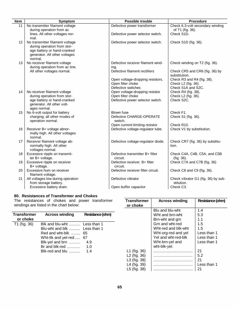
Item Symptom Possible trouble Procedure11 No transmitter filament voltage Defective power transformer Check 6.3-volt secondary winding
during operation from ac of T1 (fig. 36).lines. All other voltages nor- Defective power selector switch. Check S1D.mal.
12 No transmitter filament voltage Defective power selector switch. Check S1D (fig. 36).during operation from stor-age battery or hand-crankedgenerator. All other voltagesnormal.
13 No receiver filament voltage Defective receiver filament wind- Check winding on T2 (fig. 36).during operation from ac line. ing.All other voltages normal. Defective filament rectifiers Check CR5 and CR6 (fig. 36) by
substitution.Open voltage-dropping resistors. Check R3 and R4 (fig. 38).Open filter choke Check L2 (fig. 36).Defective switches Check S1A and S2C.
14 No receiver filament voltage Open voltage-dropping resistor Check R4 (fig. 38).during operation from stor- Open filter choke Check L2 (fig. 36).age battery or hand-cranked Defective power selector switch. Check S2C.generator. All other volt-ages normal.
15 No 6-volt output for battery Blown fuse Check F1.charging; all other modes of Defective CHARGE-OPERATE Check S1 (fig. 36).operation normal. switch.
Open current-limiting resistor Check R10.16 Receiver B+ voltage abnor- Defective voltage-regulator tube. Check V1 by substitution.
mally high. All other voltagesnormal.
17 Receiver filament voltage ab- Defective voltage-regulator diode. Check CR7 (fig. 36) by substitu-normally high. All other tion.voltages normal.
18 Excessive ripple on transmit- Defective transmitter B+ filter Check C4A, C4B, C5A, and C5Bter B+ voltage. circuit. (fig. 36).
19 Excessive ripple on receiver Defective receiver. B+ filter Check C7A and C7B (fig. 36)B+ voltage. circuit.
20 Excessive hum on receiver Defective receiver filter circuit. Check C8 and C9 (fig. 36).filament voltage.
21 All voltages low during operation Defective vibrator Check vibrator G1 (fig. 36) by sub-from storage battery. stitution.Excessive battery drain. Open buffer capacitor Check C3.
80. Resistances of Transformer and ChokesThe resistances of chokes and power transformerwindings are listed in the chart below:
Transformer Across winding Resistance (ohm)or choke
T1 (fig. 36) Blk and blu-wht .......... Less than 1Blu-wht and blk .......... Less than 1Red and wht-blk ........ 65Wht-tlk and yel-red ..... 67Blk-yel and brn .......... 4.9Br and blk-red ............ 1.0Blk-red and blu .......... 1.4
Transformer Across winding Resistance (ohm)or choke
Blu and blu-wht 1.4Wht and brn-wht 5.3Brn-wht and grn 1.1Grn and wht-red 1.5Wht-red and blk-wht 1.5Wht-org-red and yel Less than 1Yel and wht-red-blk Less than 1Wht-brn-yel and Less than 1wht-blk-yel.
L1 (fig. 36) ................................... 21L2 (fig. 36) ................................... 5.2L3 (fig. 38) ................................... 21L4 (fig. 39) ................................... Less than 1L5 (fig. 38) ................................... 21
65

Figure 36. Large power supply, rear view.
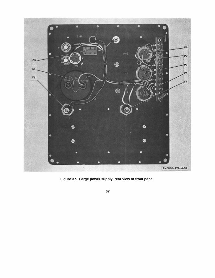
Figure 37. Large power supply, rear view of front panel.
67

Figure 38. Large power supply, underside of chassis.
Figure 39. Large power supply, area behind vibrator.
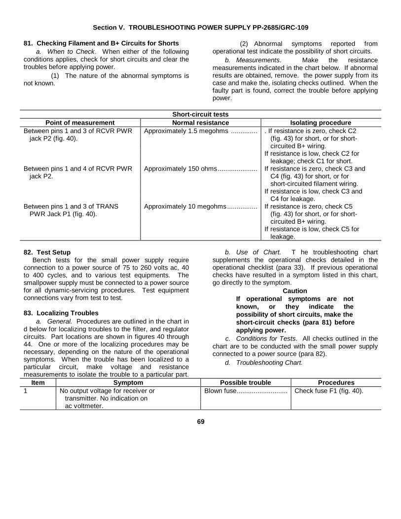
Section V. TROUBLESHOOTING POWER SUPPLY PP-2685/GRC-109
81. Checking Filament and B+ Circuits for Shortsa. When to Check. When either of the following
conditions applies, check for short circuits and clear thetroubles before applying power.
(1) The nature of the abnormal symptoms isnot known.
(2) Abnormal symptoms reported fromoperational test indicate the possibility of short circuits.
b. Measurements. Make the resistancemeasurements indicated in the chart below. If abnormalresults are obtained, remove. the power supply from itscase and make the, isolating checks outlined. When thefaulty part is found, correct the trouble before applyingpower.
Short-circuit testsPoint of measurement Normal resistance Isolating procedure
Between pins 1 and 3 of RCVR PWR Approximately 1.5 megohms .............. . If resistance is zero, check C2jack P2 (fig. 40). (fig. 43) for short, or for short-
circuited B+ wiring.If resistance is low, check C2 for
leakage; check C1 for short.Between pins 1 and 4 of RCVR PWR Approximately 150 ohms..................... If resistance is zero, check C3 and
jack P2. C4 (fig. 43) for short, or forshort-circuited filament wiring.
If resistance is low, check C3 andC4 for leakage.
Between pins 1 and 3 of TRANS Approximately 10 megohms ................ If resistance is zero, check C5PWR Jack P1 (fig. 40). (fig. 43) for short, or for short-
circuited B+ wiring.If resistance is low, check C5 for
leakage.
82. Test SetupBench tests for the small power supply require
connection to a power source of 75 to 260 volts ac, 40to 400 cycles, and to various test equipments. Thesmallpower supply must be connected to a power sourcefor all dynamic-servicing procedures. Test equipmentconnections vary from test to test.
83. Localizing Troublesa. General. Procedures are outlined in the chart in
d below for localizing troubles to the filter, and regulatorcircuits. Part locations are shown in figures 40 through44. One or more of the localizing procedures may benecessary, depending on the nature of the operationalsymptoms. When the trouble has been localized to aparticular circuit, make voltage and resistancemeasurements to isolate the trouble to a particular part.
b. Use of Chart. T he troubleshooting chartsupplements the operational checks detailed in theoperational checklist (para 33). If previous operationalchecks have resulted in a symptom listed in this chart,go directly to the symptom.
CautionIf operational symptoms are notknown, or they indicate thepossibility of short circuits, make theshort-circuit checks (para 81) beforeapplying power.
c. Conditions for Tests. All checks outlined in thechart are to be conducted with the small power supplyconnected to a power source (para 82).
d. Troubleshooting Chart.
Item Symptom Possible trouble Procedures1 No output voltage for receiver or Blown fuse........................... Check fuse F1 (fig. 40).
transmitter. No indication onac voltmeter.
69

Item Symptom Possible trouble Procedures2 No output voltage for receiver or Defective power transformer Check primary windings of T1 (fig. 40).
transmitter. Ac voltmeter indi-cation normal. Defective power selector switch Check S1.
3 No transmitter or receiver B+ Defective power transformer Check high voltage secondary ofFilament voltages normal. T1 (fig. 40).
Defective bridge rectifier Check CR1. CR2, CR3, and CR4(fig. 43) by substitution.
4 No transmitter B+. All other Defective rectifier Check CR2 arid CR4 (fig. 43) byvoltages normal. substitution.
5 No receiver B+. All other volt- Open in receiver B+ filter circuit Check R2 (fig. 41) and R3 (fig. 43).ages normal.
6 No transmitter filament voltage. Defective power transformer Check 6.3-volt secondary windingAll other voltages normal. of T1 (fig. 40).
7 No receiver filament voltage. All Defective power transformer Check receiver filament windingother voltages normal. of T1 (fig. 40).
Defective filament voltage recti- Check CR6 and CR7 (fig. 42) byfier. substitution.
Open voltage-dropping resistor Check R1 (fig. 41).Open filter choke Check L1 (fig. 44).
8 Receiver B+ abnormally high. Defective voltage-regulator tube Check V1 by substitution.All other voltages normal.
9 Receiver filament voltage abnor- Defective voltage-regulator diode Check CR5 (fig. 44) by substitution.normally high. All other voltagesnormal.
10 Excessive ripple on transmitter Defective filter capacitor Check C5 (fig. 43).B+ voltage.
11 Excessive ripple on receiver B+ Defective receiver B+ filter circuit Check C1 and C2 (fig. 43).voltage
12 Excessive ripple on receiver Defective receiver B+ filter circuit Check C3 and C4 (fig. 43).filament voltage.
84. Resistances of Transformer and ChokeThe resistances of the power transformer and filterchoke are given in the chart below:
Transformer Winding Resistanceor choke (ohm)
L1 (fig. 44) .......................... 5.5T1 (fig. 40) Red and blk ...... 55
Blk and red-yel .. 55Blk-yel and brn .. 4.3
Transformer Winding Resistanceor choke (ohm)
Brn and blk-red 1.0Blk-red and blu 1.2Blu and blu-wht 1.2Wht and grn-wht 4.7Grn-wht and grn 1.0Grn-and red-wht 1.3Red-wht and blk-wht 1.3Orn-red and yel Less than 1Yel and blu Less than 1Blu and blk-yel Less than 1
70

Figure 40. Small power supply, rear view of front panel.
71

Figure 41. Small power supply, resistor coverremoved.
Figure 42. Small power supply, right side view.
72

Figure 43. Small power supply, bottom view.Figure 44. Small power supply, underside of
chassis.
Section VI. TROUBLESHOOTING VOLTAGE REGULATOR CN-690/GRC-109
85. GeneralThe voltage regulator is an accessory unit supplied -withthe radio set and may be used in place of the largepower supply when the receiver and transmitter areoperated from the hand-cranked generator. The voltageregulator is used to regulate B+ and filament voltagesfrom the hand-cranked generator for the receiver.Transmitter B+ and filament voltages pass from thehand-cranked generator through the voltage regulatorunaltered. Part locations in the voltage regulator areshown in figure 45; figure 60 is the schematic diagram.
86. TroubleshootingTroubleshooting the voltage regulator consists mainly ofcontinuity checks and resistance measurements. If thereceiver filament voltage is excessively high, checkselenium rectifier CR1 (fig. 45) by substitution. If thereceiver B+ voltage is excessively high, check voltageregtuator V1 by substitution.
73

Figure 45. Voltage regulators interior view, V1 and mounting bracket removed.
74

C4, TM 11-5820-474-14CHAPTER 8
REPAIRS AND ALIGNMENT
Note. All repairs and alignment may be performed by third or fourth echelon personnel.
87. General Parts Replacement TechniquesWarning: The OB2 tube contains radioactive
material. Handle carefully to avoid breakage.Parts in the transmitter and in the two power supplies
can be reached easily and replaced without specialprecautions. Special precautions are required in thereceiver, because the internal construction is extremelycompact. Careless replacement of parts in the receivermay result in damage to adjacent parts or unsatisfactoryperformance caused by incorrect placement of criticalleads or parts. For soldering operations in the receiver,use a pencil-type iron with a maximum capacity of 25watts. Before removing a part in the rf amplifier andconverter circuits, note the position, of the part and itsleads. Install replacement parts in essentially the sameposition as the original part to avoid undesired couplingand spurious oscillations.
a. If regulator CR7 in the large power supply mustbe replaced, make the following adjustments beforeconnecting the receiver to the large power supply:
(1) Replace CR7.(2) Connect a 4.5-ohm, 1-watt resistor across
pins 1 and 4 of RCVR PWR. plug P5.(3) Operate the power supply from a fully
charged 6-volt battery.(4) Set the multimeter for dc volts and
connect it across the 4.5-ohm resistor(positive probe to pin 4).
(5) Locate resistors R3 and R4 (fig. 38).(6) Adjust the slider on R4 until the
multimeter indicates 1.3 volts.(7) Disconnect the 6-volt battery.(8) Connect the variable transformer (para
63) between an ac supply and the ac inputto the large power supply.
(9) Adjust the voltage selector dial on thevariable transformer until the ac input tothe power supply is exactly 110 volts.
(10) Turn the power selector switch (fig. 10) onthe power supply to 110.
(11) Adjust the slider on R3 until themultimeter connected across the 4.5ohmresistor indicates 1.3 volts. Do notreadjust R4.
b. If regulator CR5 in the small power supply mustbe replaced, make the following adjustments beforeconnecting the receiver to the small power supply:
(1) Replace CR5.(2) Connect a 4.5-ohm, one-watt resistor
across pins 1 and 4 of RCVR PWR.plug P2.
(3) Set the multimeter for dc volts andconnect it across the 4.5-ohm resistor(positive probe to pin 4).
(4) Connect the variable transformer betweenan ac supply and the ac input to the powersupply.
(5) Adjust the voltage selector dial on thevariable transformer until the ac input tothe small power supply is exactly 110volts.
(6) Turn the power selector switch on thesmall power supply to 110.
(7) Remove the small cover at the top centerof the front panel (fig. 41).
(8) Adjust the slider on R1 until the voltmeterconnected across the 4.5ohm resistorindicates 1.3 volts.
88. Test Equipment and Special Tools Required forReceiver Alignment Tests
Item Applicable Common nametechnical manual
Signal Generator TM 11-5551A SignalAN, URM-25A. generator
Electronic TM 11-6625-320-12 Ac vtvmVoltmeterME-30A/U.
Seven-pin testsocket adapter.
Resistor, 4,000ohms, 1 watt.
Insulated align-ment tool.
75

C4, TM 11-5820-474-14
89. Alignment InstructionsAlign the receiver as instructed in paragraphs 90through 92. Refer to figures 19 and 20 for the locationof components. Use the insulated alignment tool foradjusting transformers and coils.
90. If. Alignment ProcedureNote: Locations of if. transformers are shown in figure
19.a. Set the signal generator to 455 kc, 30-percent
modulation at 400 cps.b. Remove V2, replace it with the test socket
adapter, and insert V2 into the test adapter.c. Couple the signal generator through the CX-
1.363/U test lead (part of the signal generator) to pin 6of the test adapter.
d. Connect the ac vtvm to PHONES jacks J3 andJ4.
e. Connect the 4,000-ohm resistor in parallel withthe ac vtvm at the PHONES jacks.
f. Set the receiver TUNING control to 3 mc, shortthe ANT post to the GRD post with a jumper wire, andturn the BEAT OSC control to OFF.
g. Turn the GAIN control two thirds down from theMAX position.
h. Set the rf signal generator output to give areference reading of 5 volts on the ac vtvm.
i. Adjust both tuning slugs in if. transformer T3 toobtain maximum indication on the ac vtvm. Adjust theoutput level of the signal generator as necessary tomaintain approximately 5 volts on the ac vtvm.
j. Adjust both tuning slugs in if. transformer T2 toobtain maximum indication on the ac vtvm.
k. Adjust both tuning slugs in if. transformer T1 toobtain maximum indication oh the ac vtvm.
l. Adjust the transformer slugs a second time inthe order indicated in i through k above.
91. Rf Alignment ProcedureLocations of adjustable coils and capacitors in the rf
section are shown in figure 20. Connect the 4,000-ohmresistor and the ac vtvm in parallel across the PHONESjacks. Connect the signal generator output through theImpedance Adapter MX-1074/ URM-25 (part of thesignal generator) to i the ANT and GRD posts. Reducethe output of the rf signal generator as necessary during
alignment to maintain a constant reading on the acvtvm.
a. Alignment of Band 1 (3 to 6 Mc).(1) Set the RANGE switch to 1.(2) Set the signal generator to 3 mc, 30-
percent modulation at 400 cps.(3) Set the receiver TUNING control to 3 me,
the GAIN control to two thirds down fromMAX, and turn the BEAT OSC control toOFF.
(4) Adjust L7 for maximum output on the acvtvm.
(5) Set the receiver TUNING control andsignal generator to 3.2 me and adjust L1and LA for maximum output on the acvtvm.
(6) Set the receiver TUNING control and thesignal generator to 6 me and adjust C7 formaximum output on the ac vtvm.Note. Look for two peaks and select theone that corresponds to the leastcapacitance in C7.
(7) Set the receiver TUNING control and thesignal generator to 5.5 me and adjustcapacitors C1 and C4 for maximumoutput on the ac vtvm.
b. Alignment of Band 2 (6 to 12 Mc).(1) Set the RANGE switch to 2.(2) Set the signal generator to 6 me, 30-
percent modulation at 400 cps.(3) Set the receiver TUNING control to 6 me,
the GAIN control to two thirds down fromMAX, and turn the BEAT OSC control toOFF.
(4) Adjust L8 for maximum output on the acvtvm.
(5) Set the receiver TUNING control and thesignal generator to 6.5 mc and adjust L2and L5 for maximum output on the acvtvm.
(6) Set the receiver TUNING control and thesignal generator to 12 mc and adjust C8for maximum output on the ac vtvm.Note: Look for two peaks and select theone that corresponds to the leastcapacitance in C8.
76
C4, TM 11-5820-474-14
(7) Set the receiver TUNING and the signalgenerator to 11.5 mc and adjust C2 and C5 for maximum output on the ac vtvm.
c. Alignment of Band 3 (12-24 Mc).(1) Set the RANGE switch to 3.(2) Set the signal generator to 12 mc, 30-
percent modulation at 400 cps.(3) Set the receiver TUNING control to 12
mc, the GAIN control to two thirds downfrom MAX, and turn the BEAT OSCcontrol to OFF.
(4) Adjust L9 for maximum output on the acvtvm.
(5) Set the receiver TUNING control and thesignal generator to 13 me and adjust L3and L6 for maximum output on the acvtvm.
(6) Set the receiver TUNING control and thesignal generator to 24 mc and adjust C9for maximum output on the ac vtvm.Note: Look for two peaks and select theone that corresponds to the leastcapacitance in C9.
(7) Set the receiver TUNING control and therf signal generator to 22 mc and adjust C3and C6 for maximum output on the acvtvm.
92. Adjustment and Check of Beat-FrequencyOscillator
The slug of coil L10, referred to in d below, protrudesfrom the bfo assembly shown in figure 19. Connect theoutput of pie rf signal generator to pin 6 of V2. Connectthe headset to the PHONES jack on the receiver.
a. Set the rf signal generator to 455 kc; turn themodulation off.
b. Turn the GAIN control to the normal receptionlevel (about two thirds from MAX).
c. Set the BEAT OSC control to 0.d. Adjust the slug in L10 to obtain a zero beat. If
the tuning is broad, increase the clockwise setting of theGAIN control.
e. Rotate the BEAT OSC control to position 2 onone side of 0; then to position 2 on the other side of 0.At either position 2 setting, a high beat note(approximately 4 kc) should be heard.
77/(78 BLANK)

C4, TM 11-5820-474-14
CHAPTER 9
GENERAL SUPPORT TESTING PROCEDURES
93. Generala. Testing procedures are prepared for use by
Electronic Field Maintenance Shops and ElectronicService Organizations responsible for general supportmaintenance of electronic equipment to determine theacceptability of repaired signal equipment. Theseprocedures set forth specific requirements that repairedsignal equipment must meet before it is returned to theusing organization. The testing procedures may also beused as a guide for the testing of equipment that hasbeen repaired at third echelon if the proper tools andtest equipment’s are available. A summary of theperformance standards is given in paragraph 107.
b. Comply with the instructions preceding the chartbefore proceeding to the chart. Perform each test insequence. Do not vary the sequence. For each step,perform all the actions required in the Test equipmentcontrol settings and Equipment under test controlsettings columns; then perform each specific testprocedure and verify it against its performancestandard.
94. Test Equipment, Tools, and MaterialsAll test equipment, tools, materials, and other
equipment required to perform the testing proceduresgiven in this section are listed in the charts below andare authorized under TA 11-17 and TA 11-100(11-17).
a. Test Equipment.Federal
Nomenclature stock No. Technical manualMultimeter 6625-242-5023 TM 11-5527
TS-352(*) Ua,Audio Oscillator 6625-192-5094 TM 11-6625-261-12
TS-382(*) Ub.Electronic 6625-669-0742 TM 11-6625-320-12
VoltmeterME-30(*) Uc.
R.F. Signal 6625-309-5381 TM 11-5551AGenerator SetAN URM-25A
Nomenclature Federalstock No. Technical manual
Variable Power 5950-235-2086TransformerCN-16(*) Ud.
Multimeters TM 11-6625-200-12
ME-26A U,ME-26B U, andME-26C U.
Wattmeter 6625-790-2746 TM 11-6625-446-15AN URM-120.
a Indicates TS-352 U, TS-352A U, and TS-352B U.b Indicates TS-382 U, TS-382A U, TS-382B U, TS-382EU, and TS-382F U.c Indicates ME-30 U, ME30A U,ME-30B U, and ME-30CU.d Indicates CN-16 U and CN-16B U.
b. Tools and Materials.
(1) Insulated alignment tool.(2) Resistor, fixed, noninductive, 50 ohms, 20
watts.(3) Resistor, fixed, wirebound, 4.500 ohms,
10% 50 watts.(4) Resistor, fixed, wirebound 4.2 ohms, 10%,
50 watts.(5) Resistor, fixed, wirebound 5,000 ohms,
10%, 5 watts.(6) Resistor, fixed, composition 4.5 ohms,
10%, 1 watt.(7) Resistor, fixed, composition 4,000 ohms,
10%, 1 2 watt.(8) Storage battery, 6-volt.
c. Other Equipment.Equipment Federal Technical
stock No. ManualContinental adapter (to con- None None.
vert round European-typepower pins to flat Ameri-can type).
Set-up transformer, 1:2 None None.turns ratio.
95. Fabrication of Special Test Leadsa. Test Cable No. 1 (fig. 46). Test cable No. 1 is
used to connect the output of the CN-16 (*) U to theprimary of the step-up transformer when either powersupply is tested. One cable is required.
78.1

C4, TM 11-5820-474-14
Figure 46. Test Cable No. 1, construction details.
b. Test Cable No. 2 (fig. 47). Test cable No. 2 isused to connect the secondary of the step-up.transformer to the ac input power cable when eitherpower supply is tested. One cable is required.
Figure 47. Test cable No. 2, construction details.
c. Test Cable No. 3 (fig. 48). Test cable No. 3 isused to connect the RCVR PWR jack to the dummyload resistors when either power supply is tested. Onecable is required.
Figure 48. Test cable No. 3, construction details.
d. Test Cable No. 4 (fig. 49). Test cable No. 4 isused to connect the TRANS PWR jack to the dummyload resistors when either power supply is tested. Onecable is required.
5 PIN CONNECTOR(AMPHENOL 91-5MOR EOUIV.I
Figure 49. Test cable No. 4, construction details.
e. Test Cable No. 5 (fig. 50). Test cable No. 5 is ageneral-purpose test lead. It is used in several tests toconnect test points to equipment input terminals. Fourcables are required.
Figure 50. Test cable No. 5, construction details.
f. Test Cable No. 6 (fig. 51). Test cable No. 6 isused to connect the output of the transmitter to the inputof the AN/URM120 when transmitter output power istested. One cable is required.
Figure 51. Test cable No. 6, construction details.
g. Test Cable No. 7 (fig. 52). Test cable No. 7 isused to connect the output of the AN/URM-25Aimpedance adapter to the input of the receiver. Onecable is required.
Figure 52. Test cable No. 7, construction details.
79

C4, TM 11-5820-474-14
96. Power Supply PP-2684/GRC-109 Physical Tests and Inspectiona. Test Equipment and Materials. None.b. Test Connections and Conditions. Do not connect the large power supply to a power source.c. Procedure.
Test equipment Equipment under testcontrol settings control settings Test procedure Performance standard
N/A Controls may be in any position a. Inspect the large power supply case and a. No damage or loose or missing parts arepanel for loose or missing parts, dam- evident. External surfaces do not showage, and condition of finish. bare metal. Panel lettering is legible.
b. Inspect the power cables and plugs for b. The power cables and plugs are in gooddamage and signs of deteriorated insu- condition, free from damage and deteri-lation. orated insulation.
c. Turn the power selector switch and the c. The switches operate freely withoutCHARGE-OPERATE switch to each of binding or excessive looseness. Thethe indicated-positions. switch detents are positive. The knobs
are tight on the shafts and are properlyindexed.
d. Remove the fuseholders and inspect d. The fuseholders are in serviceable con-them for damage; inspect the fuses for dition. The fuses are of the proper valueproper size and rating. as indicated on the panel.
97. Power Supply PP-2685/GRC-109 Physical Tests and Inspectiona. Test Equipment and Materials. None.b. Test Connections and Conditions. Do not connect the small power supply to a power source.c. Procedure.
Test equipment Equipment under testcontrol settings control settings Test procedure Performance standard
N/A Controls may be in any position a. Inspect the small power supply case a. No damage or loose or missing parts areand panel for loose or missing parts, evident. External surfaces, do not showdamage, and condition of finish. bare metal. Panel lettering is legible.
b. Inspect the power cable and plug for b. The power cable and plug are in gooddamage and signs of deteriorated insula- condition, free from damage and deteri-tion. orated insulation.
c. Turn the power selector switch to each c. The switch operates freely withoutof the indicated positions. binding or excessive looseness. The
switch detents are positive. The knob istight on the shaft and is properly indexed.
d. Remove the fuseholder and inspect it d. The fuseholder is in serviceable condi-(for damage; inspect the fuse for proper tion. The fuse is rated at 2 amp.size and rating.
80
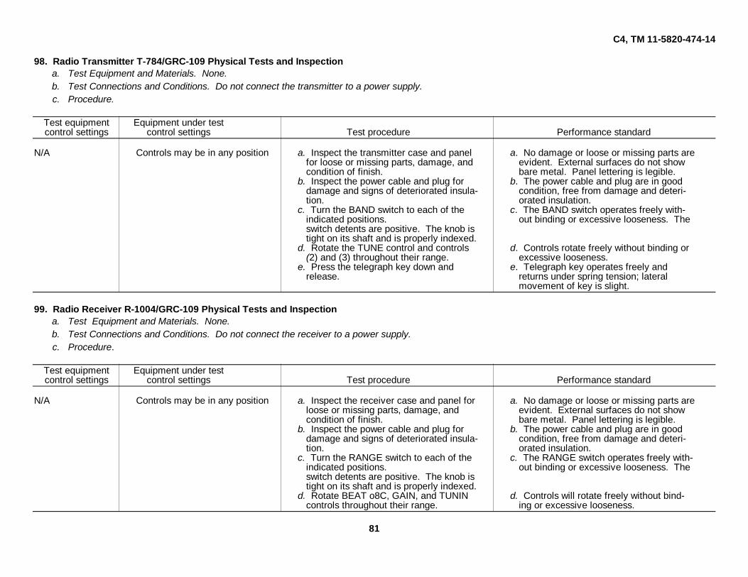
C4, TM 11-5820-474-14
98. Radio Transmitter T-784/GRC-109 Physical Tests and Inspectiona. Test Equipment and Materials. None.b. Test Connections and Conditions. Do not connect the transmitter to a power supply.c. Procedure.
Test equipment Equipment under testcontrol settings control settings Test procedure Performance standard
N/A Controls may be in any position a. Inspect the transmitter case and panel a. No damage or loose or missing parts arefor loose or missing parts, damage, and evident. External surfaces do not showcondition of finish. bare metal. Panel lettering is legible.
b. Inspect the power cable and plug for b. The power cable and plug are in gooddamage and signs of deteriorated insula- condition, free from damage and deteri-tion. orated insulation.
c. Turn the BAND switch to each of the c. The BAND switch operates freely with-indicated positions. out binding or excessive looseness. Theswitch detents are positive. The knob istight on its shaft and is properly indexed.
d. Rotate the TUNE control and controls d. Controls rotate freely without binding or(2) and (3) throughout their range. excessive looseness.
e. Press the telegraph key down and e. Telegraph key operates freely andrelease. returns under spring tension; lateral
movement of key is slight.
99. Radio Receiver R-1004/GRC-109 Physical Tests and Inspectiona. Test Equipment and Materials. None.b. Test Connections and Conditions. Do not connect the receiver to a power supply.c. Procedure.
Test equipment Equipment under testcontrol settings control settings Test procedure Performance standard
N/A Controls may be in any position a. Inspect the receiver case and panel for a. No damage or loose or missing parts areloose or missing parts, damage, and evident. External surfaces do not showcondition of finish. bare metal. Panel lettering is legible.
b. Inspect the power cable and plug for b. The power cable and plug are in gooddamage and signs of deteriorated insula- condition, free from damage and deteri-tion. orated insulation.
c. Turn the RANGE switch to each of the c. The RANGE switch operates freely with-indicated positions. out binding or excessive looseness. Theswitch detents are positive. The knob istight on its shaft and is properly indexed.
d. Rotate BEAT o8C, GAIN, and TUNIN d. Controls will rotate freely without bind-controls throughout their range. ing or excessive looseness.
81
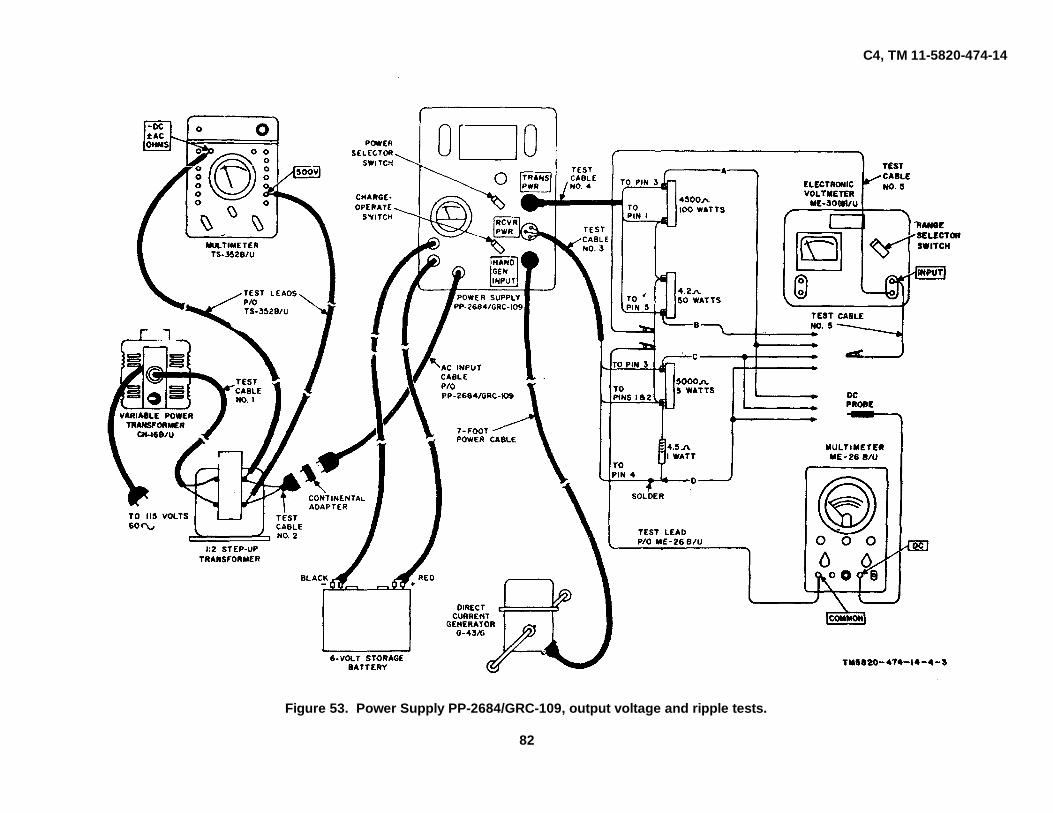
C4, TM 11-5820-474-14
Figure 53. Power Supply PP-2684/GRC-109, output voltage and ripple tests.
82

C4, TM 11-5820-474-14
101. Power Supply PP-2685/GRC-109 Output Voltage and Ripple Tests
a. Test Equipment and Materials.Multimeter TS-352(*)/UElectronic Voltmeter ME-30(*)/UElectronic Multimeter TS-505(*)/UVariable Power Transformer CN-16(*)/UStep-up transformer, 1:2 turns ratioContinental adapterTest cable No. 1Test cable No. 2Test cable No. 3Test cable No. 4Test cable-No. 5 (2)Resistor, 4,500 ohms, 100 wattsResistor, 4.2 ohms, 50 wattsResistor, 5,000 ohms, 5 wattsResistor, 4.5 ohms, 1 watt
b. Test Connections and Conditions. Connect the equipment as shown in figure 54. Turn on the test equipment and allow 15 minutes to warm up beforeproceeding. Be sure the voltage selector dial on the CN-16(*)/U is set to zero.
c. Procedure.
Step Test equipment Equipment under test Test procedure Performance standardNo. Control settings control settings
1 TS-352(*)/U: PP-2685/CRC-109: a. Connect the test leads from the ME-30(*)/U a. None.FUNCTION: AC VOLTS Power selector switch: 220 and the TS-505(*)/U to agree with connection
ME-30(*)/U: A, figure 54.Range selector switch: b. Adjust the voltage selector dial on the CN- b. None.
10V. 16(*)/U for in indication of 220 volts o theTS-505 (*)/U: TS-352(*)/U.
FUNCTION: +D. C. c. Note the indication on the ME-30()/U. c. ME-30(*)/U indication is less thanRANGE: 1000V 10 volts.
d. Note the indication on the TS-605(*)/U d. TS-505(*)/U indication 450 volts± 25.
e. Adjust the voltage selector dial on the CN- e. None.16(*)/U for an indication of 75 volts on theTS-352(*)/U.
f. Turn the power selector switch on the PP- f. None.2685/GRC-109 to 75.
g. Note the indication on the ME-30(*)/U g. ME-30(*)/U indication is less than10 volts.
h. Note the indication on the TS505*)/U h. TS-505(*)/U Indication is 450 volts± 25.
i. Turn the power selector switch on the PP- i. None.2685/G R C-109 to 110.
j. Adjust the voltage selector dial on the CN- j. None.16(*)/U for an indication of 110 volts on theTS-352(*)/U.
k. Note the Indication on the ME-30(*)/U k. ME-30(*)/U indication is less than10 volts.
l. Note the indication on the TS-505(*)/U l. TS-505(*)/U indication is 450 volts±25.
2 As last indicated As last indicated a. Connect the test lead from the ME-30(*)/U a. None.to agree with connection B, figure 54.
b. Note the indication on the ME-930()/U b. ME-30SO)/U indication is 6.3 volts±0.4.
c. Adjust the voltage selector dial on the CN- c. None.16(*)/U for an indication of 75 volts on theTS-352()/U.
d. Turn the power selector switch on the PP- d. None.2685/GRC-109 to 75.
e. Note the indication on the ME-30(*)/U e. ME-30(*)/U Indication is 6.3 volt±0.4.
f. Turn the power selector switch on the PP- f. None.2685/GRC-109 to 220.
g. Adjust the voltage selector dial on the CN- g. None.16(*)/U for an indication of 220 volts on theTS-352(*)/U.
h. Record the indication on the ME-30()/U h. ME-30(*)/U indication is 6.3 volts±0.4.
3 As last indicated As last indicated a. Connect the test leads from the ME-30(*)/U a. None.and the TS-505(*)/U to agree with connectionC, figure 54.
b. Turn the rang selector switch on the ME- b. None.30(*)/U to 0.1 volt.
c. Turn the RANGE switch on the TS-505(*)/U c. None.to 200 V.
d. Note the Indication on the ME-30(*)/U d. ME-30(*)/U indication is less than0.04 volt.
e. Note the indication on the TS-505()/U e. TS-505(*)/U indication is 100 volts±10
f. Adjust the voltage selector dial on the CN- f. None.16(*)/U for an indication of 75 volts on theTS-352(*)/U.
g. Turn the power selector switch on the PP- g. None.2685/GRC-109 to 75.
h. Note the indication on the ME-30(*)/U h. ME-30(*)/U indication is less thn0.04 volts.
i. Note the indication on the TS-505()/U i. TS-505(*)/U indication is 100 volts±10.
j. Turn the power selector switch on the PP- j. None.2685/GRC-109 to 110.
k. Adjust the voltage selector dial on the CN- k. None.16(*)/U for an indication of 110 volts on theTS-352(*)/U.
l. Note the indication on the ME-30(*)/U l. ME-30S)/U indication is less than0.04 volt.
m. Note the indication on the TS-505(*)/U m. TS-505(*)/U Indication is 100 volts±10.
4 As last indicated As last indicated a. Connect the test leads from the IE-30(a)/U a. None.and the TS-505(*)/U to agree with connectionD, figure 53.
b. Turn the RANGE switch on the TS-505(*)/U b. None.to 2 V.
c. Note the indication on toe ME-30(*)/U c. ME-30(*)/U indication is less than0.04 volt.
d. Note the indication on the TS-505(*)/U d. TS-505()/U indication is 1.35 volts±0.1.
e. Adjust the voltage selector dial on the CN- e. None.16(*)/U for :in indication of 75 volts on theTS-3J52()/U.
f. Turn the power selector switch on the PP- f. None.2684/(;RC-109 to 75.
g. Note the indication on the Ml:-30(*)/U g. ME-30(*)/U indication is less than0.04 volt.
h. Note the indication on the TS-505(*)/U h. TS-505(*)/U indication is 1.35 volts± 0.1.
i. Turn the power selector switch on the PP- i. None.2684/GRC-109 to 220.
j. Adjust the voltage selector dial on the CN- j. None.16(*)/U for an indication of 220 volts on theTS-352(*)/U.
k. Note the indication on the ME-30(*)/U k. ME-30(*)/U indication is less than0.04 volts.
I. Note the indication on the TS-505(*)/U l. TS-505(*)/U indication is 1.35 volts±0.1.
5 As last indicated As last indicated a. Turn the power selector switch on the FP- a. None.2684/GRC-109 to OFF.
b. Unplug the PP-26.,4/GRC-!09 ac input b. None.cable.
c. Disconnect the ME-30*)/U test leads c. None.d. Connect the test lead from the TS-505(*)/U d. None.
to agree with connection A, figure 53.e. Turn the RANGE switch on the TS-505(*)/U e. None.
to 1000 V.f. Turn the power selector switch on the PP- f. None.
2684/GRC-109 to BAT.g. Note the indication on the TS-SCS(*)/UL g. TS-505(*)/U indication is 450 volts
6 As last indicated As last indicated a. On the PP-2654/CRC-109, remove the a. None.cover from the HAND GEN INPUT and con-nect the G-43/C (fig. 53).
b. Turn the power selector switch on the PP- .b. None.2684/GRC-109 to OFF.
c. Operate the crank on the G-43/G at 60 rpm; c. TS-505(*)/U indication is 450 voltsnote the indication on the TS-505(*)/U, ± 25.
83

C4, TM 11-5820-474-14
This page intentionally left blank
85

C4, TM 11-5820-474-14
Figure 54. Power Supply PP-2685/GRC-109, output voltage and ripple tests.
86

C4, TM 11-5820-474-14
100. Power Supply PP-2684/GRC-109 Output Voltage and Ripple Testsa. Test Equipment and Materials.
Multimeters TS-352(*)/UElectronic Voltmeter ME-30(*)/UElectronic Multimeter TS-505(*)/UVariable Power Transformer CN-16(*)/UDirect Current Generator G-43/GStorage battery, 6-volt7-foot power cableTest cable No. 1Test cable No. 2Test cable No. 3Test cable No. 4Test cable No. 5 (2)Step-up transformer, 1:2 turns ratioContinental adapterResistor, 4,500 ohms, 100 wattsResistor, 4.2 ohms, 50 wattsResistor, 5,000 ohms, 5 wattsResistor, 4.5 ohms, 1 watt
b. Test Connections and Conditions. Connect the equipment, except the G-43/G, as shown in figure 53. Turn on the test equipment and allow it to warm upfor 15 minutes before proceeding. Be sure the voltage selector dial on the CN16(*)/U is set to zero.
c. Procedure.
Step Test equipment Equipment under test Test procedure Performance standardNo. Control settings control settings
1 TS-352(*) U: PP-2684 GRC-109: a. Connect the test leads from the ME-30(*)/U a. None.FUNCTION: AC VOLTS Power selector switch: 220 and the TS-505(*)/U to agree with connection
ME-30(*) U: CHARGE-OPERATE switch A in figure 53,Range selector switch: OPERATE. b. Adjust the voltage selector dial on the CN- b. None
10V. 16(*)/U for an indication of 220 volts on theTS-352(*)/U.
FUNCTION: D.C. c. Note the indication on ME-30(*)/U c. ME-30(*)/U indication is less than 5RANGE: 1000V volts.
d. Note the indication on TS-505(*)/U d. TS-505(*) indication is 450 volts± 25.
e. Adjust the voltage selector dial on the CN- e. None.16(*)/U for an indication of 75 volts on theTS-352(*)/U.
f. Turn the power selector switch on the PP- f. None.2684/GRC-109 to 75.
g. Note the indication on ME-30(*)/U g. ME-30(*)/U indication is less than 5volts.
h. Note the indication on TS-505(*)/U h. TS-505(*)/U indication is 450 volts± 25.
i. Turn the power selector switch on the PP- i. None.2684/GRC-109 to 110.
j. Adjust the voltage selector dial on UN- j. None.16(*)/U for an indication of 110V on the TS-352(*)/U.
k. Record the indication on the ME-30(*)/U k. ME-30(*)/U indication is less than 5volts.
l. Record the indication on the TS-505(*)/U l. TS-505(*)/U indication is 450 volts± 25.
2 As last indicated As last indicated a. Connect the test lead from the ME-30(*)/U a. None.to agree with connection B, figure 53.
b. Note the indication on the ME-30(*)/U b. ME-30(*)/U indication is 6.3 volts± 0.4.
c. Adjust the voltage selector dial on the CN- c. None.16(*)/U for an indication of 75 volts on theTS-352(*)/U.
d. Turn the power selector switch on the PP- d. None.2684/GRC-109 to 75.
e. Note the indication on the ME-30(*)/U e. ME-30(*)/U indication is 6.3 volts± 0.4.
f. Turn the power selector switch on the PP- f. None.2684/GRC-109 to 220.
g. Adjust the voltage selector dial on the CN- g. None.16(*)/U for an indication of 220 volts on theTS-352(*)/U.
h. Note the indication on the ME-30(*)/U h. ME-30(*)/U indication is 6.3 volts± 0.4.
3 As last indicated As last indicated a. Connect the test leads from the ME-30(*)/U a. None.and the TS-505(*)/U to agree with connectionC, figure 53.
b. Turn the range selector switch on the ME- b. None.30(*)/U to 0.1 volt.
c. Turn the RANGE switch on the TS-505(*)/U c. None.to 200 volts.
d. Note the indication on the ME-30(*)/U d. ME-30(*)/U indication is less than± 0.04 volt.
e. Note and record indication on TS-505(*)/U e. TS-505(*)/U indication is 100 volts± 10.
f. Adjust the voltage selector dial on the CN. f. None.16('*)/U for an indication of 75 volts on theTS-352(*)/U.
g. Turn the power selector switch on the PP- g. None.2684/GRC-109 to 75.
h. Note the indication on the ME-30(*)/U h. ME-30(*)/U indication is less than0.04 volt.
i. Note the indication on the TS-505(*)/U i. TS-505(*)/U indication is 100 volts ·±10.'
j. Turn the power selector switch on the PP- j. None.2684-/GtC-109 to 110.
k. Adjust the voltage selector dial on the CN- k. None.16(*)/U for an indication of 110 volts on theTS-352(*)/U.
l. Note the indication on the ME-30(*)/U l. ME-30(*)/U indication is less than0.04 volt.
m. Note the indication on the TS-505(*)/U m. TS-505(*)/U indication is 100 volts± 10
4 As last indicated As last indicated a. Connect the test leads from the ME-30(*)/U a. None.and the TS-505(*)/U to agree with connectionD, figure 54.
b. Turn the RANGE switch on the TS-505(*)/U b. None.to 2 V.
c. Note the indication on the ME-30(*)/U c. ME-30(*)/U indication is less than0.04 volt.
d. Note the Indication on the TS-505(*)/U d. TS-505(*)/U Indication is 1.35 volts± 0.1.
e. Adjust the voltage selector dial on the CN- e. None.16(*)/U for an Indication of 75 volts on theTS-352(*)/U.
f. Turn the power selector switch on the PP- f. None,2685/GRC-109 to 75.
g. Note the indication on the ME-30(*)/U g. ME-30(*)/U indication is less than0.04 volt.
h. Note the Indication on the TS-505(*)/U h. TS-505(*)/U indication 1.35 volts± 0.1.
i. Turn the power selector switch on the PP- i. None.2685/GRC-109 to 220V.
j. Adjust the voltage selector dial on the CN- j. None.16(*)/U for an indication M 220 volts on theTS-352(*)/U.
k. Record the indication on the ME-30()/U k. ME-30(*)/U indication is less than0.04 volt
l. Record the indication on the TS-505(*)/U l. TS-505(*)/U indication is 1.35 volts+ 0.1.
87

C4, TM 11-5820-474-14
This page left blank intentionally.
89

C4, TM 11-5820-474-14
Figure 55. Transmitter power output test.
90

C4, TM 11-5820-474-14
102. Radio Transmitter T-784/GRC-109 Power Output Testa. Test equipment and Materials.
wattmeter AN/URM-120Power Supply PP-2684/GRC-109, PP-2685/GRC-109, or equivalentCrystals, 3.0, 4.0, 4.5, and 5.5 mcTest cable No. 6
b. Test Connections and Conditions. Connect the equipment as shown in figure 55. Turn on the equipment and allow 15 minutes to warm up beforeproceeding.
c. Procedure.
Step Test equipment Equipment under test Test procedure Performance standardNo. Control settings control settings
1 AN/URM-120: T-784/GRC-109: a. Plug the 3-mc crystal into the crystal a. None.Power range selector: Band switch: socket.
50 WATTS. Exciter tuning: 10 b. Depress the key and adjust the exciter tun- b. None.PP-2684/GRC-109: Power amplifier: 10 ing control for maximum brilliance in the
Power selector switch: 110 Antenna TUNE: LO Z 50 exciter lamp.CHARGE-OPERATE switch: c. Depress the key and adjust the power am- c. None.
OPERATE. plifier tuning control for maximum brilliancein the power amplifier lamp.
d. Depress the key and adjust the antenna d. None.TUNE control for maximum brilliance in theantenna lamp.
e. Repeat b, c, and d above e. None.f. Note the indication on AN/URM-120 f. AN/URM-120 indication is more than
10 watts.2 Same as step 1 T-784/GRC-109: a. Remove the 3. O-mc crystal and insert the a. None.
Band switch: 1 5.5-mc crystal.Exciter tuning: 95 b. Repeat step lb through e b. None.Power amplifier: 95 c. Note the indication on the AN/URM-120 c. AN/URM-120 indication is more thanAntenna TUNE: LO Z 50 5 watts.
3 Same as step 1 T-784/GRC-109: Repeat step 1b through f with the 5.5-mc -cry- Same as step 1a through f.Band switch: 2 tal installed.Exciter tuning: 20Power amplifier: 30Antenna TUNE: LO Z 50
4 Same as step 1 T-784/GRC-109: a. Remove S.5-mc crystal and insert 4.5-mc a. None.Band switch: 2 crystal (9.0-mc output).Exciter tuning: 75 b. Repeat step lb through f b. Same as step 1a through f.Power amplifier: 85Antenna TUNE: LO Z 50
5 Same as step 1 T-784/GRC-109: Repeat step lb through f with the 4.5-mc crys- Same as step 1a through f.Band switch: 3 tal installed (9.0-mc output).Exciter tuning: 35Power amplifier: 40Antenna tune: LO Z 50
6 Sam as step 1 T-784/GRC-109: a. Remove the 4.5 -m crystal and install the a. None.Band switch: 3 4.0-mc crystal (16-mc output).Exciter tuning : 85 b. Repeat step 1b through f b. Same as step 1a through f.Power amplifier: 95Antenna TUNE: LO Z 50
7 Same as step 1 T-784/GRC-109: Repeat step lb through f with the 4.0-mc crys- Same as step 1a through f.Bind switch: 4 tal (16-me output).Exciter tuning: 60Power amplifier: 80Antenna TUNE: LO Z 50
8 Same as step 1 T-784/ORC-109: a. Remove the 4. 0-mc crystal and install the Same as step 1a through f.Band switch: 4 5.5-mc crystal (22-me output).Exciter tuning: 100 b. Repeat step 1b through f.Power amplifier: 95Antenna TUNE: LO Z 50
91

C4, TM 11-5820-474-14
This page left blank intentionally.
93

C4, TM 11-5820-474-14
Figure 56. If. Bandwidth test.
94

C4, TM 11-5820-474-14
101. Radio receiver R-1004/GRC-109 If. Bandwidth Testa. Test Equipment and Materials.
RF. Signal Generator Set AN/URM-25AElectronic Voltmeter ME-30(*)/UResistor, noninductive, 50 ohms, 20 wattsResistor, 4,000 ohms, 1/2 wattTest cable No. 5 (4)Power Supply PP-2685/GRC-109 or PP-2684/GRC-109, or equivalent
b. Test Connections and Conditions. Connect the equipment as shown in figure 56. Turn on all equipment and allow 15 minutes to warm up beforeproceeding.
c. Procedure.
Step Test equipment Equipment under test Test procedure Performance standardNo. Control settings control settings
1 PP-2685/GRC-109: R-1004/GRC-109: a. Adjust main tuning dial on AN/URM-2SA to 455 kc a. None.Power selector switch: 110 GAIN: 2/3 from MAX b. Adjust % MODULATION control on AN/URM-25A for b. None.
AN/URM-25A: BEAT OSC: OFF 30% modulation.FREQUENCY BAND switch: D c. Adjust MICROVOLTS control of AN/URM-25A to c. None.CARRIER CONTROL: maximum obtain reference reading of 5 volts on ME-30(*)/U.
counterclockwise. d. Note and record output level on AN/URM-2SA. This d. None.CARRIER RANGE switch: D is the output reference level.Main dial: 455 on the e. Increase the output level from the AN/URM-25A 6 db a. None.
frequency scale. (twice) above the reference level noted in d above.MULTIPLIER dial: 1000 f. Turn the main tuning dial on the AN/URM-2SA to f. ME-30(*)/U indication it 5% MODULATION control: increase the output frequency above 455 kc until the volts.
maximum counterclockwise. ME-30(*)/U indicates 6 volts.MOD SELECTOR: 400 g. Note and record the output frequency indicated n the g. AN/URM-25 indication isMICROVOLTS control: maxi- AN/URM-25A. higher than 459.5 kc.
mum counterclockwise. h. Turn the main tuning dial on the AN/URM-25A to h. None.ME. 30(*)/U: decrease the output frequency below 455 kc until the
RANGE SELECTOR switch: 10V ME-30s)/U indicates 5 volts.i. Note the output frequency indicated on the AN/URM- i. AN/URM-2A indication is
25A. not lower than 450.6 kc.j. Increase the rf output level from the AN/UR-25SA j. None.
60 db (1,000 times) above the reference level noted ind above.
k. Turn the main tuning dial on the AN/URM-2SA to k. ME-3S0)/U indication isincrease the output frequency above 4S5 kc until the 5 volts.ME-S30(*)/U indicates S volts.
l. Note the output frequency indicated on the AN/URM- l. AN/URI-2SA indication:25A. not higher than 470 kc.
m. Turn the main tuning dial on the AN/URM-26A to m. None.decrease the output frequency below 455 kc until theME-30(*)/U indicates 5 volts.
n. Note the output frequency Indicated on the AN/URM- n. AN/URM-25A indication is25A. not lower than 440 kc.
95

C4, TM 11-5820-474-14
Figure 57. Receiver signal-to-noise ratio test.
96

C4, TM 11-5820-474-14104. Radio Receiver R-1004/GRC-109 Signal-to-Noise Ratio Test
a. Test Equipment and Materials.R. F. Signal Generator Set AN/URM-25AElectronic Voltmeter ME-30(*)/UResistor, 4,000 ohms, 1/2 wattPower Supply PP-2685/GRC-109, PP-2684/GRC-109, or equivalentTest cable No. 5 (4)Test cable No. 7
b. Test Connections and Conditions. Connect the equipment as shown in figure 57. Turn on the test equipment and allow 15 minutes to warm up beforeproceeding.
c. Procedure.Step Test equipment Equipment under test Test procedure Performance standardNo. Control settings control settings
1 PP-2685/GRC-109: R-1004/GRC-109: a. Disconnect the output of the AN/URM-25A from the a. None.Power selector switch: 110 GAIN: 2/3 from MAX input to the R-1004/GRC-109.
AN/URM-25A: BEAT OSC: OFF b. Record the indication (in db) on the ME-30(*)/U. b. None.FREQUENCY BAND switch: F RANGE: 1 This is the noise level of the receiver.CARRIER CONTROL: maximum- TUNING: 3 mc c. Reconnect the output of the AN/URM-25 to-the input c. None.
counterclockwise. of the R-1004/GRC-109.CARRIER RANGE switch: D d. Adjust the output level of the AN/URM-25A to 5 d. None.Main tuning dial: 3.0 on the microvolts, modulated 30%.
frequency scale. e. Record the indication (in db) on the ME-30(*)/U e. None.MULTIPLIER dial: 1000 f. Subtract the level obtained in b above from the level f. Difference in levels is 10% MODULATION control: obtained In e above. This difference is the signal-to- db or greater.
maximum counterclockwise. noise ratio.MOD SELECTOR: 400MICROVOLTS control: maxi-
mum counterclockwise.ME-30(*)/U:
Range selector switch: 0 DB2 Same as step 1 except: Same as step 1 Repeat step 1a through f at 6.0 mc Same as step 1a through f.
AN/VURM-23A: except:Main tuning dial: 6.0 mc TUNING: 6 mc
3 Same as step 2 Same as step 1 Repeat step 1a through f at 6.0 mc on band 2 Same as step 1a through f.except:
RANGE: 2TUNING: 6 mc
4 Same as step 1 except: Same as step 1 Repeat step 1a through f at 12.0 mc on band 2 Same as step 1a through f.AN/URM-25A: except:
Main tuning dial: 12.0 mc RANGE: 2FREQUENCY BAND switch: G TUNING: 12 mc
5 Same as step 4 Same as step 1 Repeat step 1a through f at 12.0 mc on band 3 Same as step 1a through f.except:RANGE: 3TUNING: 12 mc
6 Same as step 1 except: Same as step 1 Repeat step 1a through f at 24.0 mc on band 3 Same as step 1a through f.ANI/URY-2SA except:
FREQUENCY BAND switch: H RANGE: 3Main dial: 24 mc TUNING: 24 mc
97

C4, TM 11-5820-474-14
This page left blank intentionally.
99

C4, TM 11-5820-474-14
Figure 58. Receiver image rejection test.
100

C4, TM 11-5820-474-14
105. Radio Receiver R-1004/GRC-109 Image Rejection Testa. Test Equipment and Materials.
R.F. Signal Generator Set AN/URM-25AElectronic Voltmeter ME-30(*)/UPower Supply PP-2685/GRC-109, PP-2684/GRC-109, or equivalentResistor, 4,000 ohms, 1/2 wattTest cable No. 5 (4)Test cable No. 7
b. Test Connections and Conditions. Connect the equipment as shown in figure 58. Turn on all equipment and allow 15 minutes to warm up beforeproceeding.
c. Procedure.
Step Test equipment Equipment under test Test procedure Performance standardNo. Control settings control settings
1 PP-2685/GRC-109: R-1004/GRC-109: a. Adjust the output level of the AN/URM-25A to 10 a. None.Power selector switch: 110 GAIN: 2/3 from MAX microvolts, modulated 30%.
AN/URM-25A: BEAT OSC: OFF b. Carefully adjust the main tuning dial on the AN/URM- b. None.FREQUENCY BAND switch: F RANGE: 1 25A for maximum indication on the ME-30(*)/U.CARRIER CONTROL: maximum TUNING: 6 mc c. Adjust the receiver GAIN control to obtain an indica- c. None.counterclockwise. tion of 4 volts on the ME-30(*)/U.CARRIER RANGE switch: D d. Adjust the main tuning dial on the AN/URM-25A to d. None.Main tuning dial: 6 mc 6.91 mc.MULTIPLIER dial: 1000 e. Adjust the output level of the AN/URM-25A to approx- e. None.% MODULATION control: imately 100.000 microvolts.
maximum counterclockwise. f. Carefully adjust main tuning dial on the AUI/URM-25A f. None.MOD 8ELECTOR: 400 for maximum indication on the ME-30(*)/U, and reduceMICROVOLTS control: maxi- the AN/URM-25A output level as necessary to keep the
mum counterclockwise. ME-30(*)/U meter on scale.ME-30(*)/U: g. When the ME-30(*)/U indication is maximum, adjust g. None.
Range selector switch: 10V the output level of the AN/URM-25A to obtain an indi-cation of 4 volts on the ME-30(*)/U.
h. Note the output level on the AN/URM-25A h. AN/URM-25A indication is500 microvolts or higher.
2 Same as step 1 except: Same as step 1 Repeat step 1a through b at a signal frequency of 12 mc Same as step 1a through hAN/URM-25A: RANGE: 2 and an image frequency of 12.91 mc.
Main timing dial: 12.0 mc TUNING: 12 mcFREQUENCY BAND switch: G
3 Same as step 1 except: Same as step 1 Repeat step 1a through h at a signal frequency of 24 mc Same as step 1a through hAN/URM-25A: RANGE: 3 and an image frequency of 24.91 mc.
Main timing dia: 24.0 mc TUNING: 24 mcFREQUENCY BAND switch: H
101

C4, TM 11-5820-474-14
Figure 59. Receiver audio response test.
102

C4, TM 11-5820-474-14106. Radio Receiver R-1004/GRC-109 Audio Response Test
a. Test Equipment and Materials.R.F. Signal Generator Set AN/URM-25AElectronic Voltmeter ME-30(*)/UPower Supply PP-2685/GRC-109, PP-2684/GRC-109, or equivalentAudio Oscillator TS-382(*)/UResistor, 4,000 ohms, 1/2 wattTest Cable No. 5 (4)Test Cable No. 7
b. Test Connections and Conditions. Connect the equipment as shown in figure 59. Turn on all equipment and allow a 15-minute warm up before proceeding.c. Procedure.
Step Test equipment Equipment under test Test procedure Performance standardNo. Control settings control settings
PP-2685/GRC-109: R-104/GRC-109: a. Adjust the output level control on the TS-382(*)/U to a. None.Power selector switch: 110 GAIN: 1/2 from MAX obtain an indication of approximately 4 volts on the
TS-382(*)/U: BEAT OSC: OFF output level meter.Main tuning dial: 100 RANGE: 1 b. Adjust the output level of the AN/URM-25A to 10 b. None.RANGE switch: X10 TUNING: 3 mc microvolts, modulated 30%.HEATER switch: OFF c. Carefully adjust the main tuning dial on the AN/URM- c. None.OSC switch: ON 25A for maximum indication on the ME -30(*)/U.ATTENUATOR: 10 d. Adjust the output level of the AN/URM-25A to obtain d. ME-30(*)/U indication is +13Output level control: maximum an indication of +13 db on the ME.-30()/U. This is the db.
counterclockwise. 1,000-cycle reference level.FREQ METER switch: OFF e. Adjust the main tuning dial on the TS-382(*)/U to 30 e. None.
AN/URM-25SA: f. Adjust the c MODUIATION control on the AN/URM- f. None.FREQUENCY BAND SWITCH: F 25A to maintain 309 modulation.CARRIER CONTROL: maximum g. Note the indication on the ME-30(*)/U g. ME-30(*)/U indication ms 13
counterclockwise. db ± 3.CARRIER RANGE switch: F h. Adjust the main tuning dial on the TS-382(*)/U to 50 h. None.Main tuning dial: 3 mc i. Adjust the % MODULATION control on the AN/URM- i. None.MULTIPLIER dial: 1000 25A to maintain 30n modulation.% MODULATION control: maxi- j. Note the indication on the ME-30(*)/U j. ME-30()/U indication is 13
mum counterclockwise. db ± 3.MOD SELECTOR: EXT k. Adjust the main tuning dial on the TS-382()/U to 80 k. None.MICROVOLTS control: maxi- l. Adjust the % MODULATION control on the AN/URM- l. None.
mum counterclockwise. 25A to maintain 30% modulation.XTAL CAL: OFF m. Note the indication on the ME-30(*)/U m. ME-30(*)/U indication is 13
ME-30(*)/U: db ±3.Range selector switch: +20 DB n. Adjust the main tuning dial on the TS-382(*)/U to 130 n. None.
o. Adjust the % MODULATION control on the AN/URM- o. None.25A to maintain 30% modulation.
p. Note the indication on the -ME-30(*)/U p. ME-30(*)/U indication is 13 db ± 3.q. Adjust the main tuning dial on the TS-382(*)/U to 160 q. None.r. Adjust the % MODULATION control on the AN/URM- r. None.
25A to maintain 30% modulation.s. Note the indication on the ME-30(*)/U s. ME-30{*)/U indication is 13 db ± 4.5.t. Adjust the main tuning dial on the TS-382(*)/U to 30 t. None.u. Turn the RANGE switch on the TS-382()/U to X100 I None.v. Adjust the % MODULATION control on the AN/URM- v. None.
25A to maintain 30% modulation.w. Record the indication on the ME-30(*)/U w. ME-30(*)/U is less than +3 db.
103

107. Summary of Test DataPersonnel may find it convenient to arrange the checklist in a manner similar to that shown below.a. POWER SUPPLY PP-2684/GRC-109
Output Voltage Ripple VoltageTest Performance Test PerformanceData Standard Data Standard
(1) TRANSMITTER B+ OUTPUT VOLTAGE AND RIPPLE220 volts ac input ______ 450 ±25 ______ 5 volts max75 volts ac input ______ 450 ±25 ______ 5 volts max
110 volts ac input ______ 450 ±25 ______ 5 volts max6 volts ac input ______ 450 ±25
hand-cranked genera-tor input ______ 450 ±25
(2) RECEIVER B+ OUTPUT VOLTAGE AND RIPPLE220 volts ac input ______ 100 ±10 ______ 0.04 volts max75 volts ac input ______ 100 ±10 ______ 0.04 volts max
110 volts ac input ______ 100 ±10 ______ 0.04 volts max(3) RECEIVER FILAMENT OUTPUT VOLTAGE AND RIPPLE
220 volts ac input ______ 1.35 ±0.1 ______ 0.04 volts max75 volts ac input ______ 1.35 ±0.1 ______ 0.04 volts max
110 volts ac input ______ 1.35 ±0.1 ______ 0.04 volts max(4) TRANSMITTER FILAMENT OUTPUT VOLTAGE
220 volts ac input ______ 6.3 ±0.475 volts ac input ______ 6.3 ±0.4
110 volts ac input ______ 6.3 ±0.4
b. POWER SUPPLY PP-2685/GRC-109
Output Voltage Ripple VoltageTest Performance Test PerformanceData Standard Data Standard
(1) TRANSMITTER B+ OUTPUT VOLTAGE AND RIPPLE220 volts ac input ______ 450 ±25 ______ 10 volts max75 volts ac input ______ 450 ±25 ______ 10 volts max
110 volts ac input ______ 450 ±25 ______ 10 volts max
105
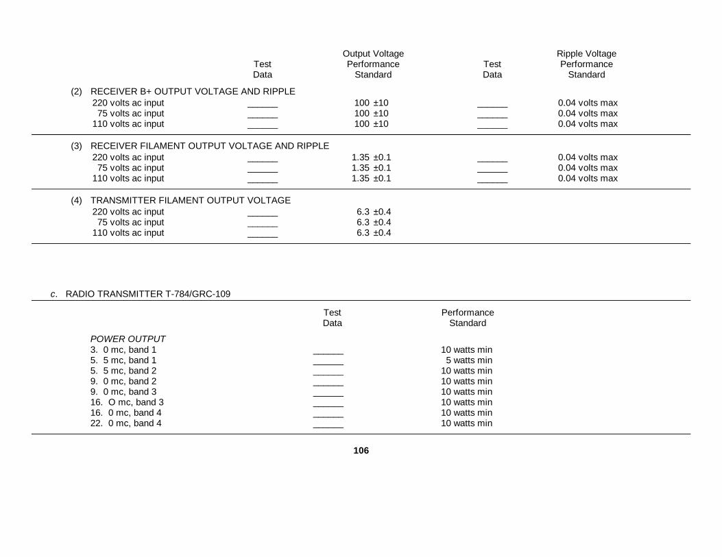
Output Voltage Ripple VoltageTest Performance Test PerformanceData Standard Data Standard
(2) RECEIVER B+ OUTPUT VOLTAGE AND RIPPLE220 volts ac input ______ 100 ±10 ______ 0.04 volts max75 volts ac input ______ 100 ±10 ______ 0.04 volts max
110 volts ac input ______ 100 ±10 ______ 0.04 volts max
(3) RECEIVER FILAMENT OUTPUT VOLTAGE AND RIPPLE220 volts ac input ______ 1.35 ±0.1 ______ 0.04 volts max75 volts ac input ______ 1.35 ±0.1 ______ 0.04 volts max
110 volts ac input ______ 1.35 ±0.1 ______ 0.04 volts max
(4) TRANSMITTER FILAMENT OUTPUT VOLTAGE220 volts ac input ______ 6.3 ±0.475 volts ac input ______ 6.3 ±0.4
110 volts ac input ______ 6.3 ±0.4
c. RADIO TRANSMITTER T-784/GRC-109
Test PerformanceData Standard
POWER OUTPUT3. 0 mc, band 1 ______ 10 watts min5. 5 mc, band 1 ______ 5 watts min5. 5 mc, band 2 ______ 10 watts min9. 0 mc, band 2 ______ 10 watts min9. 0 mc, band 3 ______ 10 watts min16. O mc, band 3 ______ 10 watts min16. 0 mc, band 4 ______ 10 watts min22. 0 mc, band 4 ______ 10 watts min
106

C4, TM 11-5820-474-14
This page intentionally left blank.
108
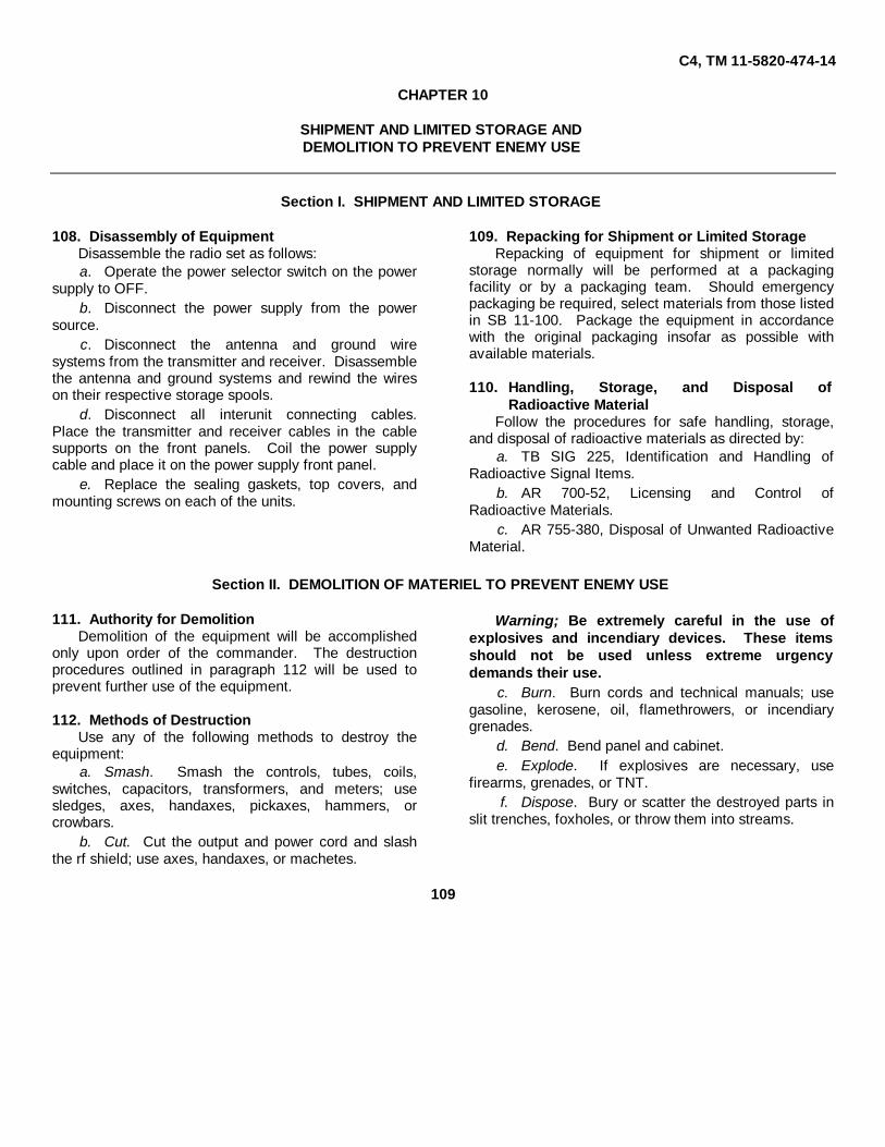
C4, TM 11-5820-474-14
CHAPTER 10
SHIPMENT AND LIMITED STORAGE ANDDEMOLITION TO PREVENT ENEMY USE
Section I. SHIPMENT AND LIMITED STORAGE
108. Disassembly of EquipmentDisassemble the radio set as follows:a. Operate the power selector switch on the power
supply to OFF.b. Disconnect the power supply from the power
source.c. Disconnect the antenna and ground wire
systems from the transmitter and receiver. Disassemblethe antenna and ground systems and rewind the wireson their respective storage spools.
d. Disconnect all interunit connecting cables.Place the transmitter and receiver cables in the cablesupports on the front panels. Coil the power supplycable and place it on the power supply front panel.
e. Replace the sealing gaskets, top covers, andmounting screws on each of the units.
109. Repacking for Shipment or Limited StorageRepacking of equipment for shipment or limited
storage normally will be performed at a packagingfacility or by a packaging team. Should emergencypackaging be required, select materials from those listedin SB 11-100. Package the equipment in accordancewith the original packaging insofar as possible withavailable materials.
110. Handling, Storage, and Disposal ofRadioactive Material
Follow the procedures for safe handling, storage,and disposal of radioactive materials as directed by:
a. TB SIG 225, Identification and Handling ofRadioactive Signal Items.
b. AR 700-52, Licensing and Control ofRadioactive Materials.
c. AR 755-380, Disposal of Unwanted RadioactiveMaterial.
Section II. DEMOLITION OF MATERIEL TO PREVENT ENEMY USE
111. Authority for DemolitionDemolition of the equipment will be accomplished
only upon order of the commander. The destructionprocedures outlined in paragraph 112 will be used toprevent further use of the equipment.
112. Methods of DestructionUse any of the following methods to destroy the
equipment:a. Smash. Smash the controls, tubes, coils,
switches, capacitors, transformers, and meters; usesledges, axes, handaxes, pickaxes, hammers, orcrowbars.
b. Cut. Cut the output and power cord and slashthe rf shield; use axes, handaxes, or machetes.
Warning; Be extremely careful in the use ofexplosives and incendiary devices. These itemsshould not be used unless extreme urgencydemands their use.
c. Burn. Burn cords and technical manuals; usegasoline, kerosene, oil, flamethrowers, or incendiarygrenades.
d. Bend. Bend panel and cabinet.e. Explode. If explosives are necessary, use
firearms, grenades, or TNT.f. Dispose. Bury or scatter the destroyed parts in
slit trenches, foxholes, or throw them into streams.
109

TM 11-5820-474-14
APPENDIX I
REFERENCES
Following is a list of references applicable and available for Radio Set AN/GRC-109.
DA Pam 310-4 Index of Technical Manuals, Technical Bulletins, Supply Manuals (Types 7, 8, and 9),Supply Bulletins and Lubrication Orders.
DA Pam 310-7 US Army Index of Modification Work Orders.
SM 11-4-5180-R09 Radio Repair Tool Kit TK-115/G.
TM 11-5094 Frequency Meter AN/URM-79.
TM 11-5095 Frequency Meter AN/URM-80.
TM 11-5120 Frequency Meters AN/URM-32 and AN/URM-32A and Power Supply PP1243/U.
TM 11-5122 Direct Current Generator G-43/G.
TM 11-5129 Oscilloscopes AN/USM-50A, B, and C.
TM 11-5551B R.F. Signal Generator Set AN/URM-25B.
Operator's, Organizational, Direct Support and General Support Maintenance RepairParts and Special Tools Lists (Including Depot Maintenance Repair Parts andSpecial Tools): Transformer, Variable, Power CN-16/U, CN16A/U, and CN-16B/U.
TM 11-6625-320-12 Operator's and Organizational Maintenance Manual: Voltmeter, Meter ME30A/U andVoltmeters, Electronic ME-30B/U, ME-30C/U, and ME-30E./U.
TM 11-6625-366-15 Operator's, Organizational, DS, GS, and Depot Maintenance Manual: Multimeter TS-352B/U.
TM 11-6625-446-15 Operator's, Organizational, DS, GS, and Depot Maintenance Manual: WattmeterAN/URM-120.
TM 11-6625-486-14&P Operator's, Organizational Direct Support, and General Support Maintenance ManualIncluding Repair Parts and Special Tools Lists (Including Depot Maintenance RepairParts and Special Tools) for Frequency Meters AN/ USM-159, AN/USM-159A, andAN/USM-159B.
TM 38-750 The Army Maintenance Management System (TAMMS).
TM 43-0139 Painting Instructions for Field Use.
Change 6 111

TM 11-5820-474-14
TM 740-90-1 Administrative Storage of Equipment.
TM 750-244-2 Procedures for Destruction of Electronics Materiel to Prevent Enemy Use (ElectronicsCommand).
TM 11-6625-200-15 Operator's, Organizational, DS, GS, and Depot Maintenance Manual: Multimeters ME-26A/U, ME-26B/U, ME-26C/U and ME-26D/U.
TM 11-6625-200-24P Organizational, Direct Support, and General Support Maintenance Repair Parts andSpecial Tools Lists (Including Depot Maintenance Repair Parts and Special Tools):Multimeters ME-26A/U, ME-26B/U, ME-26C/U, and ME-26D/U.
TM 11-6625-261-12 Operator's and Organizational Maintenance Manual: Audio Oscillators TS382A/U, TS-382B/U, TS-382D/U, TS-382E/U, and TS-382F/U.
TM 11-6625-274-12 Operator's and Organizational Maintenance Manual: Test Sets, Electron Tube TV-7/U,TV-7A/U, TV-7B/U, and TV-7D/U.
TM 11-6625-300-20P Organizational Maintenance Repair Parts and Special Tools Lists: Frequency MeterAN/URM-79.
Change 6 112

C4, TM 11-5820-474-14
APPENDIX II
BASIC ISSUE ITEMS LIST (BIIL) AND ITEMS TROOPINSTALLED OR AUTHORIZED LIST (ITIAL)
Section I. INTRODUCTION
1. ScopeThis appendix lists basic issue items and items troopinstalled or authorized required by the crew/operator forinstallation, operation,, and maintenance of Radio SetAN/GRC-109.
2. GeneralThis Basic Issue Items and Items Troop Installed orAuthorized List is divided into the following sections:
a. Basic Issue Items List - Section II. A list, inalphabetical sequence, of items which are furnishedwith, and which must be turned in with the end item.
b. Items Troop Installed or Authorized List SectionIII. A list, in alphabetical sequence, of items which, atthe discretion of the unit commander, may accompanythe end item, but are not subject to be turned in with theend item.
3. Explanation of ColumnsThe following provides an explanation of columns foundin the tabular listings:
a. Illustration. This column is divided as follows:(1) Figure Number. Indicates the figure
number of the illustration in which the item is shown.(2) Number. Not applicable.
b. Federal Stock Number. Indicates the Federalstock number assigned to the item and will be used forrequisitioning purposes.
c. Part Number. Indicates the primary numberused by the manufacturer (individual, company, firm,corporation, or government activity), which controls thedesign and characteristics of the item by means of itsengineering drawings, specifications standards, andinspection requirements, to identify an item or range ofitems.
d. Federal Supply Code for Manufacturer (FSCM).The FSCM is a 5-digit numeric code used to identify themanufacturer, distributor, or Government agency, etc.,and is identified in SB 708-42.
e. Description. Indicates the Federal item nameand a minimum description required to identify the item.
f. Unit of Measure (U/M). Indicates the standardof basic quantity of the listed item as used in performingthe actual maintenance function. This measure isexpressed by a two-character alphabetical abbreviation,(e.g., ea, in, pr, etc. When the unit of measure differsfrom the unit of issue, the lowest unit of issue that willsatisfy the required units of measure will berequisitioned.
g. Quantity Furnished with Equipment (Basic IssueItems Only). Indicates the quantity of the basic issueitem furnished with the equipment.
h. Quantity Authorized (Items Troop Installed orAuthorized Only). Indicates the quantity of the itemauthorized to be used with the equipment.
Change 5 113

C4, TM 11-5820-474-14
Section II. BASIC ISSUE ITEMS LIST
(1) (2) (5) (6) (7)Illustration Federal (3) (4) Unit Qty
(A) (B) stock Part Description of furnFig. Item number number FSCM Usable meas withno. no. on code equip
3 5820-863-3500 CASE, ELECTRONICEQUIPMENT MAIN-TENANCE KIT CY-4621/GRC-109
EA 1
Section III. ITEMS TROOP INSTALLED OR AUTHORIZED LIST
(1) (2) (3) (4) (5) (6)Federal Part Description Unitstock number FSCM Usable on of Qty
number code meas auth
7340-240-5943 KNIFE TL-29 EA 15120-856-3735 53-6 07885 PLIERS EA 15120-897-2036 Crl XceLite SCREWDRIVER EA 15120-856-1958 A11534 99799 WRENCH: OPEN END EA 15120-608-0116 WRENCH: ALLEN NO. 8 EA 1
Next printed page is 117.
Change 5 114

C4, TM 11-5820-474-14
APPENDIX III
MAINTENANCE ALLOCATION
Section I. INTRODUCTION
A3-1. GeneralThis appendix provides a summary of the maintenanceoperations for AN/GRC-109. It authorizes categories ofmaintenance for specific maintenance functions onrepairable items and components and the tools andequipment required to perform each function. Thisappendix may be used as an aid in planningmaintenance operations.
A3-2. Maintenance FunctionMaintenance functions will be limited to and defined asfollows:
a. Inspect. To determine the serviceability of anitem by comparing its physical, mechanical, and/orelectrical characteristics with established standardsthrough examination.
b. Test. To verify serviceability and to detectincipient failure by measuring the mechanical orelectrical characteristics of an item and comparing thosecharacteristics with prescribed standards.
c. Service. Operations required periodically tokeep an item in proper operating condition, i.e., to clean(decontaminate), to preserve, to drain, to paint, or toreplenish fuel, lubricants, hydraulic fluids, orcompressed air supplies.
d. Adjust. To maintain, within prescribed limits, bybringing into proper or exact position, or by setting theoperating characteristics to the specified parameters.
e. Align. To adjust specified variable elements ofan item to bring about optimum or desired performance.
f. Calibrate. To determine and cause correctionsto be made or to be adjusted on instruments or testmeasuring and diagnostic equipments used in precisionmeasurement. Consists of comparisons of twoinstruments, one of which is a certified standard ofknown accuracy, to detect and adjust any discrepancy inthe accuracy of the instrument being compared.
g. Install. The act of emplacing, seating, or fixinginto position an item, part, module (component or
assembly) in a manner to allow the proper functioning ofthe equipment or system.
h. Replace. The act of substituting a serviceablelike type part, subassembly, or module (component orassembly) for an unserviceable counterpart.
i. Repair. The application of maintenanceservices (inspect, test, service, adjust, align, calibrate,replace) or other maintenance actions (welding,grinding, riveting, straightening, facing, remachining, orresurfacing) to restore serviceability to an item bycorrecting specific damage, fault, malfunction, or failurein a part, subassembly, module (component orassembly), end item, or system.
j. Overhaul. That maintenance effort (service/action) necessary to restore an item to a completelyserviceable/operational condition as prescribed bymaintenance standards (i.e., DMWR) in appropriatetechnical publications. Overhaul is normally the highestdegree of maintenance performed by the Army.Overhaul does not normally return an item to like newcondition.
k. Rebuild. Consists of those services/actionsnecessary for the restoration of unserviceableequipment to a like new condition in accordance withoriginal manufacturing standards. Rebuild is the highestdegree of materiel maintenance applied to Armyequipment. The rebuild' operation includes the act ofreturning to zero those age measurements (hours,miles, etc.) considered in classifying Armyequipments/components.
A3-3. Column Entriesa. Column 1, Group Number. Column 1 lists group
numbers, the purpose of which is to identifycomponents, assemblies, subassemblies, and moduleswith the next higher assembly.
b. Column 2, Component/Assembly. Column 2contains the noun names of components, assemblies,
Change 6 117

C4, TM 11-5820-474-14
and modules for which maintenance is authorized.c. Column 3, Maintenance Functions. Column 3
lists the functions to be performed on the item listed incolumn 2. When items are listed without maintenancefunctions, it is solely for purpose of having the groupnumbers in the MAC and RPSTL coincide.
d. Column 4, Maintenance Category. Column 4specifies, by the listing of a "worktime" figure in theappropriate subcolumn(s), the lowest level ofmaintenance authorized to perform the function listed incolumn 3. This figure represents the active timerequired to perform that maintenance function at theindicated category of maintenance. If the number orcomplexity of the tasks within the listed maintenancefunction vary at different maintenance categories,appropriate "worktime" figures will be shown for eachcategory. The number of task-hours specified by the"worktime" figure represents the average time requiredto restore an item (assembly, subassembly, component,module, end item or system) to a serviceable conditionunder typical field operating conditions. This timeincludes preparation time, troubleshooting time, andquality assurance/quality control time in addition to thetime required to, perform the specific tasks identified forthe maintenance functions authorized in themaintenance allocation chart. Subcolumns of column 4are as follows:
C--Operator/CrewO--OrganizationalF--Direct SupportH--General SupportD--Depot
e. Column 5, Tools and Equipment. Column 5specifies by code, those common tool sets (not
individual tools) and special tools, test, and supportequipment required to perform the designated function.
f. Column 6, Remarks. Column 6 contains analphabetic code which leads to the remark in section IV,Remarks, which is pertinent to the item opposite theparticular code.
A3-4. Tool and Test Equipment Requirements(sec III)
a. Tool or Test Equipment Reference Code. Thenumbers in this column coincide with the numbers usedin the tools and equipment column of the MAC. Thenumbers indicate the applicable tool or test equipmentfor the maintenance functions.
b. Maintenance Category. The codes in thiscolumn indicate the maintenance category allocated thetool or test equipment.
c. Nomenclature. This column lists the noun nameand nomenclature of the tools and test equipmentrequired to perform the maintenance functions.
d. National/NATO Stock Number. This columnlists the National/NATO stock number of the specifictool or test equipment.
e. Tool Number. This column lists themanufacturer's part number of the tool followed by theFederal Supply Code for manufacturers (5-digit) inparentheses.
A3-5. Remarks (sec IV)a. Reference Code. This code refers to the
appropriate item in section II, column 6.b. Remarks. This column provides the required
explanatory information necessary to clarify itemsappearing in section II.
(Next printed page is 119.)
Change 6 118

C4, TM 11-5820-474-14
(1) (2) (3) (4) (5) (6)
MAINTENANCE CATEGORYTOOLS
GROUP COMPONENT/ MAINT. ANDNUMBER ASSEMBLY FUNCTION C O F H D EQUIP REMARKS
00 RADIO SET AN/GRC-109 Service 0.25Inspect 0.25Test 0.25 1,2,3 ATest 0.5 2,4 thru
11Align 0.5 6,7,11Repair 0.5 1,3 DRepair 1.5 2,4 thru
11
01 RADIO TRANSMITTER T-784/GRC-109 Replace 0.25,Test 0.25 2,4,11 BTest 0.25 2,4,10,
11Repair 0.75 2,4111 BRepair 0.75 2,4,10,
11
02 RADIO RECEIVER R-1004/GRC-109 Replace 0.25Test 0.25 24.,6,8, B
9,11Test 0.25 2,4 thru
9,11Align 0.25 6,7,11Repair 0.5 1,2,3 DRepair 0.75 2,4 thru B
6,8,9,11Repair 0.75 2,4 thru
9,11
0201 IF AND AUDIO CHASSIS(LISTED FOR REFERENCE ONLY)
TESTED AS PART OF NEXT HIGHER ASSEMBLY
0202 RF CHASSIS(LISTED FOR REFERENCE ONLY)
TESTED AS PART OF NEXT HIGHER ASSEMBLY
0203 BFO OSCILLATOR(LISTED FOR REFERENCE ONLY)
TESTED AS PART OF NEXT HIGHER ASSEMBLY
03 POWER SUPPLY PP-2684/GRC-109 Replace 0.25Test 0.25 4,11Test 0.5 4,5,7,8, C
11Repair 0.25 1,2,3 DRepair 0.5 4,11
04 POWER SUPPLY PP-2685/GRC-109SAME MAINTENANCE AS 03
05 REGULATOR, VOLTAGE CN-690/GRC-109 Test 0.25 4,11Replace 0-25 1Repair 0.5 4,11
Change 6 119

C4, TM 11-5820-474-14
SECTION III TOOL AND TEST EQUIPMENT REQUIREMENTSFOR
RADIO SET AN/GRC-109
TOOL OR TESTEQUIPMENT MAINTENANCE NOMENCLATURE NATIONAL/NATO TOOLREF CODE CATEGORY STOCK NUMBER NUMBER
1 O MULTIMETER AN/URM-105B 6625-00-884-1758
2 O,F,H TEST SET, ELECTRONIC TUBE TV-7D 6625-00-820-0064
3 O TOOL KIT ELECTRONIC EQUIPMENT TK-101/G 5180-00-064-5178
4 F,H MULTIMETER TS-352B/U 6625-00-553-0142
5 F,H MULTIMETER ME-26B/U 6625-00-646-9409
6 F,H RF SIGNAL GENERATOR SET AN/URM-25 6625-00-649-5193
7 F,H VOLTMETER, ELECTRONIC ME-30/U 6625-00-643-1670
8 F,H VARIABLE POWER TRANSFORMER CN-16/U 5950-00-235-2085
9 F,H AUDIO OSCILLATOR AN/URM-127 6625-00-783-5965
10 F,H WATTMETER AN/URM-120 6625-00-813-8430
11 F,H TOOL KIT, ELECTRONIC EQUIPMENT TK-105/G 5180-00-610-8177
DRSEL-MA Form1 Oct 77 6013 (Edition of 1 Oct 4 may be used until exhausted) HISA-FM 2132-77
Change 6 120

C4, TM 11-5820-474-14
SECTION IV. REMARKS
REFERENCECODE REMARKS
A OPERATIONAL TEST
B ALL EXCEPT RF STAGES
C EXCEPT OUTPUT VOLTAGE AND RIPPLE TEST
D BY AUTHORIZED PARTS REPLACEMENT
Next printed page is 135.
Change 6 121

INDEX
Paragraph Page Paragraph Page
Ac lines operation.............................................. 15a, 55 15,40Additional equipment required ........................... 10 10Alignment ....................................................... 19 20Antenna system................................................. 8e, 13b, 14 10,13, 14AntiJamming procedures................................... 25 22Audio amplifier................................................... 52 38Audio response test........................................... 106 103
Battery charging operation................................. 8d, 58 10,42Beat frequency oscillator:
Alignment .................................................... 92 77Theory......................................................... 53 38
Block diagram:Power Supply PP-2684/GRC-109............... 54 39Power Supply PP-2685/GRC-109............... 59 42Radio Receiver R-1004/GRC- 109.............. 47 36Radio Transmitter T-784/GRC-109............. 42 34
Checking filaments and B+ forshorts:
Power Supply PP-2684/GRC-109 ........ 77 63Power Supply PP-2685/GRC-109 ........ 81 69Radio Receiver R-1004/GRC-109 ........ 64 45Radio Transmitter T-784/GRC-109 ...... 71 56
Checking unpacked equipment ......................... 12 11Controls and indicators...................................... 17 17Converter ....................................................... 49 37Counterpoise grounding .................................... 14c(1) 15
Damage from improper settings ........................ 16 17Description and data.......................................... 3 3Detector............................................................. 53 38
Extension cord, description ............................... 9c 10
Forms and records ............................................ 2 3Fourth echelon testing procedures .................... 93 78
Test equipment required ............................. 94 78
Grounding system ............................................. 14c 15
Hand-cranked generatoroperation ..................................................... 15c, d;57 16; 41
If. amplifier:Alignment .................................................... 90 76Theory ....................................................... 50,51 37,38
If. bandwidth test ............................................... 103 95Image rejection test ........................................... 105 101Installation, Radio Set AN/GRC 109 ................. 14 13
Jamming, recognition and identification............. 24 22
Keying .............................................................. 46 35
Localizing troubles:Power Supply PP-2684/GRC-109 .............. 79 64Power Supply PP-2685/GRC-109 .............. 83 69Radio Receiver R-1004/GRC-109 .............. 66 46Radio Transmitter T-784/GRC-109 ............ 73 57
Lubrication ....................................................... 38 31
Maintenance:Operator's ................................................... 30 24Preventive ................................................... 31,37 24,31Second echelon .......................................... 35 31
Nomenclature and common name .................... 6 5
Operating accessories ...................................... 5b 5Operating precautions....................................... 23 22Operating procedures ....................................... 22 22Operational checklist......................................... 33 25Operator's maintenance .................................... 30 24Oscillator:
Radio Receiver R-1004/GRC-109 .............. 49c, d 37Radio Transmitter T-784/GRC-9 ................ 43 34
Output voltage and ripple tests:Power supply PP-2684/GRC-109............... 100 83Power supply PP-2685/GRC-109............... 101 87
Physical tests and inspection:Power Supply PP-2684/GRC-109 .............. 96 80Power Supply PP-2685/GRC-109 .............. 97 80Radio Receiver R-1004/GRC-109 .............. 99 81Radio Transmitter T-784/GRC-109 ............ 98 81
Power amplifier ................................................. 44 35Power cable, description ................................... 9b 10Power output test .............................................. 102 91Power Supply PP-2684/GRC-109:
Ac lines operation ....................................... 55 40Battery charging operation .......................... 8d, 58 10,42Block diagram............................................. 54 39Checking filament and B+ for shorts........... . 77 63Circuit analysis............................................ 60 42Dc resistance of coils and transformers ..... 80 65Description.................................................. 80 10Hand-cranked generator operation.............. 150c, 57 16,41Localizing troubles ...................................... 79 64Output voltage and ripple tests ................... 100 83Physical tests and Inspection ..................... 96 80Reference designation changes.................. 76 63Repairs ....................................................... 87a 75Storage battery operation ............................ 15b, 56 16, 41Technical characteristics ............................ 4c 4Test setup................................................... 78 63Troubleshooting chart ................................. 79d 64
Power Supply PP-2685/GRC-109:Block diagram............................................. 59 42Checking filaments and B+ for shorts......... 81 69Circuit analysis............................................ 60 42Dc resistance of coils and transformers ..... 84 70Description.................................................. 8d 10
135

Paragraph Page Paragraph Page
Localizing troubles....................................... 83 69Output voltage and ripple tests.................... 101 87Physical tests and inspection...................... 97 80Repairs........................................................ 87b 75Technical characteristics ............................ 4d 4Test setup ................................................... 82 69Troubleshooting chart ................................. 83d 69
Preliminary starting procedures......................... 18 20Preventive maintenance..................................... 31, 37 24, 31Purpose and use ............................................... 3 3
Radio Receiver R-1004/GRC-109:Af amplifier .................................................. 52 38Alignment .................................................... 89 76Antenna circuit ............................................ 45 35Audio response test .................................... 106 103Beat frequency oscillator ............................. 53 38Block diagram ............................................. 47 36Checking filament and B+ for shorts ........... 64 45Controls and indicators ............................... 17 17Converter..................................................... 49 37Dc resistance of coils and transformers...... 69 56Description.................................................. 8b 10Detector....................................................... 52 38If. amplifier .................................................. 50, 51 37,38If. bandwidth test......................................... 103 95Image rejection test ..................................... 105 101Isolating trouble within a stage .................... 68 54Localizing troubles....................................... 66 46Physical tests and inspection...................... 99 81Rf amplifier.................................................. 48 36Signal substitution....................................... 67 53Signal-to-noise ratio test.............................. 104 97Technical characteristics ............................ 4b 4Test equipment required for alignment........ 88 75Test setup ................................................... 65 46Troubleshooting chart ................................. 66d 46Tuning procedure........................................ 21 21
Radio Set AN/GRC-109:Alignment ..................................................... 87 75Antenna system .......................................... 8e, 13b,14 10, 13, 13Checking filament and B+
circuits for shorts .................................. 64 45Components................................................ 5 4Description................................................... 7 5Grounding system....................................... 14c 15Operating accessories ................................ 5b 5Purpose and use......................................... 3 3Relationship between units.......................... 41 34Repairs........................................................ 87 75Siting........................................................... 13 11Spares ....................................................... 5c 5Technical characteristics ............................ 4 3Test equipment required ............................. 63 45Unit interconnections .................................. 15 15
Radio Transmitter T-7b4/GRC-109:Block diagram............................................. 42 34Checking filaments and B+ for shorts......... 71 56Controls and indicators ............................... 17 17Dc resistances of coils and transformers.... 75 57Description.................................................. 8a 6Isolating trouble within a stage.................... 74 57Keying ....................................................... 46 35Localizing troubles ...................................... 73 57Oscillator..................................................... 43 4Physical tests and inspection...................... 98 81Power amplifier ........................................... 44 35Power output test ........................................ 102 91Reference designation changes.................. 70 56Technical characteristics ............................ 4a 3Test setup................................................... 72 56Troubleshooting chart ................................. 73d 57Tuning procedure........................................ 20 21
Reference designation changes:Power Supply PP-2684/GRC-109 .............. . 76 63Radio Transmitter T-784/GRC-109 ............ 70 56
Repairs and adjustment .................................... 34, 87 26, 75Resistances of coils and transformers:
Power Supply PP-2684/GRC-109 .............. . 80 65Power Supply PP-2685/GRC-109 .............. 84 70Radio Receiver R-1004/GRC-109 .............. . 69 56Radio Transmitter T-784/GRC-109 ............ 75 57
Rf amplifier . ..................................................... 48 36
Scope of manual ............................................... 1 3Second echelon maintenance ........................... 35 31Signal substitution............................................. 67 53Signal-to-noise ratio test.................................... 104 97Siting ............................................................. 13 11Spares ............................................................. 5c 5Special test leads.............................................. 95 18Starting procedure, power supplies................... 19 20Starting procedure, preliminary. ........................ 18 20Stopping procedure........................................... 21 21Storage battery operation .................................. 19b, 56 21, 41Summary of test data ........................................ 107 105
Technical characteristics:Power Supply PP-2684/GRC-109 .............. 4c 4Power Supply PP-2685/GRC-109 .............. 4d 4Radio Receiver R-1004/GRC-109 .............. 4b 4Radio Transmitter T-784/GRC-109 ............ 4a 3
Test data, summary .......................................... 107 105Test setup:
Power Supply PP2684/GRC-109 ............... 78 63Power Supply PP-2685/GRC-109 .............. 82 69Radio Receiver R-1004/GRC-109 .............. 65 46Radio Transmitter T-784/GRC-109 ............ 72 56
Troubleshooting:General instruction...................................... 61 44Procedures ................................................. 62 44Second echelon .......................................... 39 31
136

Paragraph Page Paragraph Page
Voltage Regulator CN-690/GRC-109.......... 86 73Troubleshooting chart:
Power Supply PP-2684/GRC-/109.............. 79d 64Power Supply PP-2685/GRC-109................ 83d 69Radio Receiver R-1004/GRC-109............... 66d 46Radio Transmitter T-784/GRC-109............. 73d 57
Tube testing ...................................................... 40 31
Tuning procedure:Radio Receiver R-1004/GRC-109 .............. 21 21Radio Transmitter T-784/GRC-109 ............ 20 21
Unit interconnections ........................................ 15 15Unpacking . ...................................................... 11 11Visual inspection............................................... 32 24Voltage Regulator CN-690/GRC-109:
Description.................................................. 9a 10Troubleshooting .......................................... 85, 86 73
137

This page left blank intentionally.
138

Figure 60. Voltage Regulator CN-690/GRC-109, schematic diagram.
139

COLOR CODE MARKING FOR MILITARY STANDARD RESISTORS
Figure 61. Color code marking for MIL-STD resistors.
140

Figure 62. Color code marking for MIL-STD capacitors.
141
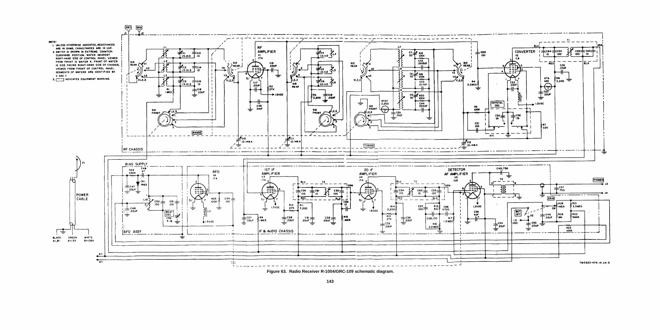
Figure 63. Radio Receiver R-1004/GRC-109 schematic diagram.
143
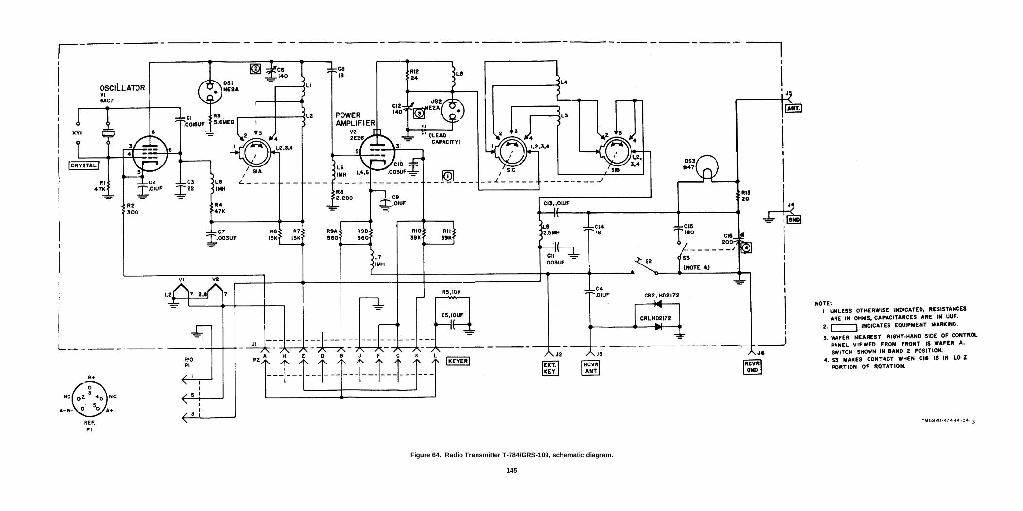
Figure 64. Radio Transmitter T-784/GRS-109, schematic diagram.
145

Figure 65. Power Supply PP-2684/GRC-109, schematic diagram.147

Figure 66. Power Supply PP-2685/GRC-109, schematic diagram.149

By Order of Secretary of the Army:
G.. H. DECKER,General, United States Army;
Official: Chief- of Staff.J. C. LAMBERT,
Major General, United States Army,The Adjutant General.
Distribution:
Active Army:
DASA (6) WRAMC (1)USASA (2) USA Trans Tml Comd (1)CNGB (1) Army Tml (I)Tech Stf, DA (1) except POE (1)CSigO (14) OSA (1)Tech Stf Bd (1) USAEPG (2)USCONARC (5) AFIP (1)USAARTYBD (1) AMS (1)USAARMBD (2) Army Pictorial Cen (2)USAIB (1) EMC (I)USARADBD (2) Yuma Test Sta (2)USAAVNBD (1) USA Strat Comm Comd (4)USAABELCTBD (1) USASSA (20)UFAATBD (1) USASSAMWO (1)ARADCOM (2) USARCARIB Sig Agcy (1)ARADCOM Rgn (2) USA Sig Msl Spt Agcy (13)OS Maj Comd (3) Sig Fld Maint Shops (3)OS Base Comd (2) USA Corps (3)LOGCOMD (2) Def Log Svc Cen (1)MI)W (1) JBUSMC (2)Armies (2) Units org under fol TOECorps (2) (2 cy ea UNOINDC)Instl (2) 1 1-7Ft -Monmouth (63) 11-16USATC AD (2) 11-5TUSATC Armor (2) 11-98USATC Engr (2) 11-117USATC Inf (2) 11-155USATC FA (2) 11-157USAOMC (3) 11-500 (Tms AA-AE) (4)Svc College (2) 11-557Br Svc/Sch (2) 11-587GENDEP (2) except 11-592Atlanta GENDEP (None) 11-597Sig Sec, GENDEP (5) 33-105Sig Dep (12) 33-107
NG: NoneUSAR: None.For explanation of abbreviations used, see AR 320-50.
U.S. GOVERNMENT PRINTING OFFICE : 1990 O - 261-872 (20984)151


The Metric System and Equivalents
Linear Measure Liquid Measure
1 centiliter = 10 milliters = .34 fl. ounce1 centimeter = 10 millimeters = .39 inch 1 deciliter = 10 centiliters = 3.38 fl. ounces1 decimeter = 10 centimeters = 3.94 inches 1 liter = 10 deciliters = 33.81 fl. ounces1 meter = 10 decimeters = 39.37 inches 1 dekaliter = 10 liters = 2.64 gallons1 dekameter = 10 meters = 32.8 feet 1 hectoliter = 10 dekaliters = 26.42 gallons1 hectometer = 10 dekameters = 328.08 feet 1 kiloliter = 10 hectoliters = 264.18 gallons1 kilometer = 10 hectometers = 3,280.8 feet
Square MeasureWeights
1 sq. centimeter = 100 sq. millimeters = .155 sq. inch1 centigram = 10 milligrams = .15 grain 1 sq. decimeter = 100 sq. centimeters = 15.5 sq. inches1 decigram = 10 centigrams = 1.54 grains 1 sq. meter (centare) = 100 sq. decimeters = 10.76 sq. feet1 gram = 10 decigram = .035 ounce 1 sq. dekameter (are) = 100 sq. meters = 1,076.4 sq. feet1 decagram = 10 grams = .35 ounce 1 sq. hectometer (hectare) = 100 sq. dekameters = 2.47 acres1 hectogram = 10 decagrams = 3.52 ounces 1 sq. kilometer = 100 sq. hectometers = .386 sq. mile1 kilogram = 10 hectograms = 2.2 pounds1 quintal = 100 kilograms = 220.46 pounds Cubic Measure1 metric ton = 10 quintals = 1.1 short tons
1 cu. centimeter = 1000 cu. millimeters = .06 cu. inch1 cu. decimeter = 1000 cu. centimeters = 61.02 cu. inches1 cu. meter = 1000 cu. decimeters = 35.31 cu. feet
Approximate Conversion Factors
To change To Multiply by To change To Multiply by
inches centimeters 2.540 ounce-inches Newton-meters .007062feet meters .305 centimeters inches .394yards meters .914 meters feet 3.280miles kilometers 1.609 meters yards 1.094square inches square centimeters 6.451 kilometers miles .621square feet square meters .093 square centimeters square inches .155square yards square meters .836 square meters square feet 10.764square miles square kilometers 2.590 square meters square yards 1.196acres square hectometers .405 square kilometers square miles .386cubic feet cubic meters .028 square hectometers acres 2.471cubic yards cubic meters .765 cubic meters cubic feet 35.315fluid ounces milliliters 29,573 cubic meters cubic yards 1.308pints liters .473 milliliters fluid ounces .034quarts liters .946 liters pints 2.113gallons liters 3.785 liters quarts 1.057ounces grams 28.349 liters gallons .264pounds kilograms .454 grams ounces .035short tons metric tons .907 kilograms pounds 2.205pound-feet Newton-meters 1.356 metric tons short tons 1.102pound-inches Newton-meters .11296
Temperature (Exact)
°F Fahrenheit 5/9 (after Celsius °Ctemperature subtracting 32) temperature

PIN: 018757-000