tlb-ps61c and tlb-ps801c power supplies overviewproducts.asg-jergens.com/asset/asg tlb-ps61c and...
TRANSCRIPT

ASG, Division of Jergens, Inc.
15700 S. Waterloo Road | Cleveland, OH 44110-3898 | Phone: (888) 486-6163 | Fax: (216) 481-4519 | Email: [email protected] | Web: www.asg-jergens.com | Revision Date: 01/03/18 1
Table of Contents
Overview .................................................................................................................. 1
General Safety Rules ................................................................................................ 2
Operations Instructions ............................................................................................ 3
Main Technical Parameters ....................................................................................... 4
Control Panel Specifications ..................................................................................... 5
Functions of Keys on Panel .............................................................................. 6
I/O Map ........................................................................................................... 9
Functional Dip Switch ................................................................................... 12
System Setting ...................................................................................................... 14
Simulated Learning ................................................................................................ 18
Grounding .............................................................................................................. 18
Servicing ................................................................................................................ 18
Warranty ................................................................................................................ 19
Overview
Thank you very much for selecting the TLB-PS61C or TLB-PS801C Counting Power Supply
Read this manual before placing tool in service or operation. Save these instructions for future reference. It is the responsibility of the employer to place the information in this manual into the hands of the operator. Failure to observe the following warnings could result in injury. When using electric tools, basic safety precautions should always be followed to reduce the risk of fire, electric shock, and personal injury.
Note: ASG is not responsible for customer modification of tools for applications on which ASG was not consulted.
• Read these instructions for the proper use of the tool.• After having read these instructions, keep them in a convenient place so you or
the operator can refer to them whenever necessary.
TLB-PS61C and TLB-PS801C Power Supplies
PLEASE NOTE: When repairing or replacing tools or components on any TLB Series purchased in 2016 or prior, please contact ASG representative

ASG, Division of Jergens, Inc.
15700 S. Waterloo Road | Cleveland, OH 44110-3898 | Phone: (888) 486-6163 | Fax: (216) 481-4519 | Email: [email protected] | Web: www.asg-jergens.com | Revision Date: 01/03/18 2
General Safety RulesElectrical Safety• Keep work area clean and well lit.
• Do not operate power tools in explosive atmospheres, such as in the presence of flammable liquids, gases, or dust. Power tools create sparks which ignite the dust or fumes.
• Keep out of reach of children and untrained personnel. Electric screwdrivers are dangerous in the hands of untrained personnel.
• Electric screwdriver plugs must match the outlet. Never modify the plug in any way. Do not use any adapter plugs with earthed (grounded) electric screwdrivers. These precautions will reduce the risk of electric shock.
• Avoid body contact during tool use with earthed or grounded surfaces such as pipes, radiators, ranges and refrigerators. There is an increased risk of electric shock if your body is earthed or grounded.
• Do not expose the electric screwdriver to rain or wet conditions as this will increase the risk of electric shock.
• Never use the cord to carry, pull, or unplug the electric screwdriver. Keep cord away from heat, oil, sharp edges, or moving parts. Damaged or entangled cords increase the risk of electric shock.
• Take proper precautions when operating a power tool outdoors. Use an extension cord suitable for outdoor use. Use of cord suitable for outdoor use reduces the risk of electric shock.
Personal Safety• Stay alert and pay attention to your surroundings when operating an electric
screwdriver. Do not use the electric screwdriver while you are tired or under the influence of drugs, alcohol, or medication, as this could result in serious personal injury.
• Use safety equipment. Always wear eye protection. Safety equipment such as dust mask, non-skid safety shoes, hard hat, or hearing protection used for appropriate conditions will reduce personal injuries.
• Ensure the switch is in the off position before plugging in to avoid accidental starting.
• Remove any adjusting keys or wrench before turning the power tool on. A wrench or a key that is left attached to a rotating part of the power tool may result in personal injury.
• Keep proper footing and balance at all times.
• Dress properly. Do not wear loose clothing or jewelry. Keep your hair, clothing, and gloves away from moving parts. Loose clothes, jewelry, or long hair can be caught in moving parts.
Power Tool Use and Care• Use the correct electric screwdriver and power supply for your application.
• Do not use the electric screwdriver or power supply if any switch is broken. Any electric screwdriver or power supply that cannot be controlled with the switch is dangerous and must be repaired.
• Disconnect the plug from the power source before making any adjustments, changing accessories, or storing the power tools. Such preventive safety measures reduce the risk of starting the power tool accidentally.
• Keep out of reach of children and untrained personnel. Electric screwdrivers are dangerous in the hands of untrained users.
• Maintain power tools. Check for misalignment or binding of moving parts, breakage of parts and any other condition that may affect the operation of the power tool. If damaged, contact ASG to have the power tool repaired before use.
• Use the power tools, accessories, and tool bits etc. in accordance with these instructions and in the manner intended for the particular type of power tool, taking into account the working conditions and the work to be performed. Use of the power tool for operations differently than intended could result in a hazardous situation.
ASG, Division of Jergens, Inc.
15700 S. Waterloo Road | Cleveland, OH 44110-3898 | Phone: (888) 486-6163 | Fax: (216) 481-4519 | Email: [email protected] | Web: www.asg-jergens.com | Revision Date: 01/03/18 3
General Safety Rules (Continued)Service• Have your electric screwdriver serviced by ASG. This will ensure that the safety and
quality of the electric screwdriver is maintained.
Operating Instructions• PLEASE NOTE: When repairing or replacing tools or components on
any TLB Series purchased in 2016 or prior, please contact an ASG representative.
• Read the operating manual thoroughly and comply with safety regulation to operate this power supply.
• Always grasp the plug of the power cord when plugging in/unplugging.
• Always secure the power supply to avoid movement.
• Do not store near oil, chemical materials, or heated objects. Do not damage the power cord by sharp object.
• If the power supply overheats or is overloaded with maximum current rating, the high-speed fuse will cut off the power. If this situation continues, stop operation immediately and contact ASG for repair.
• Do not disassemble the electric screwdriver or try to repair it yourself. Please contact ASG for repair.
• When power supply is not in use, please turn the main power switch OFF and unplug the power supply.
• The electric frequency will be lower when the voltage is adjusted to Lo or below 32V, so the torque of the electric screwdrivers will only work at the torque scale rating below 4.
Operating Instructions (Continued)• Be sure to use correct power supply with corresponding driver
• For use with TLB series electric screwdrivers. If operator uses non ASG TLB Series electric screwdrivers, parts, or accessories, it may cause the controller malfunction. As a result, all warranties will be void.
• Do not move Forward/Reverse switch or HI/LO button while tool is running.
• Turn power off before plugging in and unplugging power supply.

ASG, Division of Jergens, Inc.
15700 S. Waterloo Road | Cleveland, OH 44110-3898 | Phone: (888) 486-6163 | Fax: (216) 481-4519 | Email: [email protected] | Web: www.asg-jergens.com | Revision Date: 01/03/18 4
Model Number 68632 (TLB-PS61-C) 68639 (TLB-PS801-C)
Input Voltage AC 100-240V 50 / 60Hz AC 115/230V 50 / 60HZ
Output Voltage DC 32V/ 24V DC 40V/ 32V/ 24V
Power Consumption 60W 360W
Counting Numbers 1 - 99
Counting Method Forward as / Count down
Connecting Sensor ON / OFF
Sensing Switch Mode ON (2 Sensor) / OFF (1 Sensor)
Slow-Start Time Adj. 0.0-9.9 seconds
Slow-Start Speed Adj. L0:100% 30%-90% L1~L9 Rated speed
Start Detecting Time 0.01-9.99 seconds
Stop Detecting Time 0.1-9.9 seconds
Detecting Alarm ON/ OFF/ FF/ EF with LED and buzzer
Auto-Response/Manual Response ON / OFF
External Connection Input Forward / Reversion / Prohibit operation / Sensor Switch / resuming Switch / Confirm Switch
External Connection Output OK/ NG/ OK ALL
Electric Screwdriver Speed Control HI / LO; Slow Start
Size 7.9 x 5.1 x 3.9 in. (200 x 130 x 100 mm) 9.7 x 5.1 x 3.9 in. (247 x 130 x 100 mm)
Weight 3.4 lb (1.53 kg) 5.3 lb (2.4 kg)
Applicable Screwdrivers
68689 (TLB-C203LS), 68608 (TLB-C210L), 68609 (TLB-412L), 68610 (TLB-C412PH), 68621 (TLB-C419L), 68622 (TLB-C419P), 68670 (TLB-C203L-ESD), 68671 (TLB-C419L-ESD), 68672 (TLB-C419ESD)
68673 (TLB-C630L), 68674 (TLB-C630P), 68686 (TLB-C960PG), 68687 (TLB-C990PG), 68682 (TLB-C990L), 68683(TLB-C990P), 68684 (TLB-C9120L), 68685 (TLB-C9120P), 68688 (TLB-C9180PGW), 68691 (TLB-C9180PW), 68692 (TLB-C9180LW)
Accessories Power cord, key
Main Technical Parameters
PLEASE NOTE: When repairing or replacing tools or components on any TLB Series purchased in 2016 or prior, please contact an ASG representative

ASG, Division of Jergens, Inc.
15700 S. Waterloo Road | Cleveland, OH 44110-3898 | Phone: (888) 486-6163 | Fax: (216) 481-4519 | Email: [email protected] | Web: www.asg-jergens.com | Revision Date: 01/03/18 5
Control Panel Specifications
# Description
1 LED Indicator
2 HI/LO Speed Switch
3 Key setting lock
4 6 Pin Connector
5 Work Light
6 OK Light
7 NG Light
8 24V Light
9 32V Light
10 40V Light
11 Up-Selecting Key
12 Down-Selecting Key
13 System Build-In Reset Key
14 POWER/CLEAR key
15 Functional Selection/Confirm Key
16 Power Point
17 Power Switch
18 Output Voltage
19 I/O Inserting Hole Instruction
20 Functional Dip Switch
21 GND

ASG, Division of Jergens, Inc.
15700 S. Waterloo Road | Cleveland, OH 44110-3898 | Phone: (888) 486-6163 | Fax: (216) 481-4519 | Email: [email protected] | Web: www.asg-jergens.com | Revision Date: 01/03/18 6
Control Panel Specifications (Continued)Functions of Keys on Panel
Key Description of Function Notes
POWER: Power Switch1. When power is on and has not started the counting operation
• Hold POWER/CLEAR for 6 seconds: this will turn off counting function • NOTE: When the counting function is off, the LED screen is off
2. When power is on and the counting function is off: • Hold POWER/CLEAR for 3 seconds to turn back on the counting function
CLEAR: Clear Switch1. When the screwdriver starts the counting function:
• Hold POWER/CLEAR for 1 second to return to the original setting for the number of screws. It will beep once.• Hold for 3 seconds: Back to U1(No. 1 Setting Number) and beep 2 times
When there is NG signal, press CLEAR button to clear the NG signal
SELECT:Press and hold the SELECT button for 3 seconds to enter system setting menu: SL---SC---At---RC---SP---Ht---Lt---LL---NS---rt---rr---rS
When entering the setting menu, press and hold S button to show the function (ex: SL or SC…etc.) and with beep sound. Release the “S” button to show the setting value
CONFIRM:When DIP SW3 is ON and the user finished fastening a unit of screws, the counter requires the user to press the CONFIRM button to start the next unit
1. Refer to CONFIRM mode:When there is NG signal output. Press “CONFIRM” button to stop the NG signal output.
UP:In system menu, press the UP key to increase the number. This key will point out user set-up number and unit during the process:U1: No.1 setting number U2: No.2 setting number.U3: No.3 setting number U4: No.4 setting number.U5: No.5 setting number
When holding the UP button to show the unit number, the tool will not run.
DOWN:In system menu, press the DOWN key to decrease the number. This key will point out user set-up number and group during the process:U1: No.1 setting number U2: No.2 setting numberU3: No.3 setting number U4: No.4 setting numberU5: No.5 setting number
When holding the DOWN button to show the unit number, the tool will not run.
ASG, Division of Jergens, Inc.
15700 S. Waterloo Road | Cleveland, OH 44110-3898 | Phone: (888) 486-6163 | Fax: (216) 481-4519 | Email: [email protected] | Web: www.asg-jergens.com | Revision Date: 01/03/18 7
Control Panel Specifications (Continued)Functions of Keys on Panel (Continued)
Key Description of Function Notes
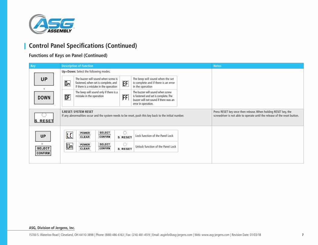
Up+Down: Select the following modes.
S.RESET: SYSTEM RESETIf any abnormalities occur and the system needs to be reset, push this key back to the initial number.
Press RESET key once then release. When holding RESET key, the screwdriver is not able to operate until the release of the reset button.
The buzzer will sound when screw is fastened, when set is complete, and if there is a mistake in the operation
The beep will sound when the set is complete and if there is an error in the operation
The beep will sound only if there is a mistake in the operation
The buzzer will sound when screw is fastened and set is complete. The buzzer will not sound if there was an error in operation.
+
+
Lock function of the Panel Lock
Unlock function of the Panel Lock

ASG, Division of Jergens, Inc.
15700 S. Waterloo Road | Cleveland, OH 44110-3898 | Phone: (888) 486-6163 | Fax: (216) 481-4519 | Email: [email protected] | Web: www.asg-jergens.com | Revision Date: 01/03/18 8
Control Panel Specifications (Continued)Functions of Keys on Panel (Continued)
Key Description of Function Notes
Enter the setup: dt ----- tt ----- Sr ---- SAdt/tt dt: The time range between each screwing process. This function will be triggered after finishing one screwing process. If user does not start next screwing process in this setting time range, the system will display “dt” until next screwing process is started. ( “01”= 1 second) tt: All the screwing processes in this list need to be finished under this setting time range. If user does not finish all the screws in this setting time range, the panel will display “tt” until all the screwing processes are finished. ( “01”= 1 minute)
Note: 1. When dt errors, restart the screwdriver to release from error status. If two or more errors occur, the red light illuminates
and buzzer sounds. LED screen will display other error messages (ex: NS). Solving these errors will turn the red light off, but dt continues to be an error.
2. When tt error occurs, completing the fastening process will release the tt error condition. Solving these errors will turn the red light off, but tt continues to be an error.• dt is for each fastening screw time interval (U #, #:1,2,3,4,5) , • tt is for the time of one whole unit (U1 ~ U #, #:2,3,4,5) , which is from U1 until the last U # screw is fastened
3. When the dt/tt error occurs, press CLEAR to release from dt/tt , counter will return to the original screw numbers setting of the current unit
Sr: Multiple function switch cycle SENSORY: multiple cycles (SW2 = ON, SW6 = ON), when the number of fastened screws U1 are complete then screwdriver stops until the sensor is triggered (SW4 = OFF). If SW4 = ON, you need to trigger twice before jumping to U2 ... and so onN: multiple cycles (SW2 = ON, SW6 = ON or SW2 = ON, SW4 = ON, SW6 = ON), when the number of fastened screws U1 are finished it will then automatically start unit 2.Sr default: N Note: When SW6 = ON, Sr parameter setting (Y/N) is only for reference. That is, Sr is a global variable, once SW6 = ON then the U2 ~ U5 SENSOR mode will follow same setting
SA: When under SENSOR mode, SA parameter setting is only effected when the SW2 = ON, SW4 = OFF.
The up and down button in the front panel can switch value (HI / LO).HI:Hi Active LO:Lo Active The default value is: HI
Note:1. When the user press the POWER + UP, panel display dt, release
POWER + UP to display values under dt mode, press “S” can go in setting “tt”, press “S” can go in setting “Sr” and then press “S” can set “SA”.
2. dt and tt cannot coexist, which mean are not able to set up at the same time. When set value dt> 0, tt will not show (cannot set value). Similarly, when the tt> 0, the dt setup value selection will not show.
1. Lock with the key (Need use the key to lock)2. When KEY is in locked position, the LED will display “PC” and counter will beep 8 times if user changes the Hi/Lo setting.
+
Unlock Function
Lock Function
ASG, Division of Jergens, Inc.
15700 S. Waterloo Road | Cleveland, OH 44110-3898 | Phone: (888) 486-6163 | Fax: (216) 481-4519 | Email: [email protected] | Web: www.asg-jergens.com | Revision Date: 01/03/18 9
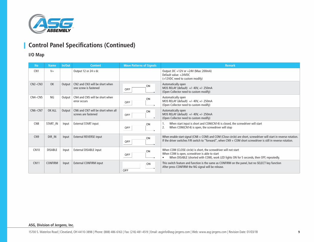
No Name In/Out Content Wave Patterns of Signals Remark
CN1 V+ Output 12 or 24 v dc Output: DC +12V or +24V (Max: 200mA)Default value: +24VDC(+12VDC need to custom modify)
CN2~CN3 OK Output CN2 and CN3 will be short when one screw is fastened
Automatically openMOS RELAY (default) +/- 40V, +/- 250mA(Open Collector need to custom modify)
CN4~CN5 NG Output CN4 and CN5 will be short when error occurs
Automatically openMOS RELAY (default) +/- 40V, +/- 250mA(Open Collector need to custom modify)
CN6~CN7 OK ALL Output CN6 and CN7 will be short when all screws are fastened
Automatically openMOS RELAY (default) +/- 40V, +/- 250mA(Open Collector need to custom modify)
CN8 START_IN Input External START input 1. When start input is short and COM(CN14) is closed, the screwdriver will start2. When COM(CN14) is open, the screwdriver will stop
CN9 DIR_IN Input External REVERSE input When enable start signal (CN8 + COM) and COM (Close circle) are short, screwdriver will start in reverse rotation. If the driver switches F/R switch to “forward”, when CN9 + COM short screwdriver is still in reverse rotation.
CN10 DISABLE Input External DISABLE input When COM (CLOSE circle) is short, the screwdriver will not startWhen COM is open, screwdriver is able to start• When DISABLE (shorted with COM), work LED lights ON for 5 seconds, then OFF, repeatedly.
CN11 CONFIRM Input External CONFIRM input This switch feature and function is the same as CONFIRM on the panel, but no SELECT key functionAfter press CONFIRM the NG signal will be release.
Control Panel Specifications (Continued)I/O Map

ASG, Division of Jergens, Inc.
15700 S. Waterloo Road | Cleveland, OH 44110-3898 | Phone: (888) 486-6163 | Fax: (216) 481-4519 | Email: [email protected] | Web: www.asg-jergens.com | Revision Date: 01/03/18 10
No Name In/Out Content Wave Patterns of Signals Remark
CN12 GATE Input External sensor switch Input a confirm signal for machine to start working.Sensor Switch: External device, you can connect one or two switches.
CN13 CLR Input External device CLEAR switch External clear switch, same as clear button on the panel. It also can disable NG signal when it is triggered
CN14 COM CN8 ~ CN13output/input signal COM port
Control Panel Specifications (Continued)I/O Map (Continued)
SW2:ON SW4: OFF
SW2:ON SW4: ON

ASG, Division of Jergens, Inc.
15700 S. Waterloo Road | Cleveland, OH 44110-3898 | Phone: (888) 486-6163 | Fax: (216) 481-4519 | Email: [email protected] | Web: www.asg-jergens.com | Revision Date: 01/03/18 11
Control Panel Specifications (Continued)I/O Connector Panel
• CN1(V+) and CN14(COM) can provide DC 24V(Default) · (DC +12V need to custom modify)
• If users need different DC voltage, they must use their own step-down circuit to decrease voltage.
• If user needs to input voltage to drive an alert instrument, do not use over DC+/-40V /, +/- 250mA voltage.
Control Panel Specifications (Continued)I/O Connector Panel Terminal Connecting Diagram: (To take factory default: MOS RELAY I/O for example)
Output:
Input:

ASG, Division of Jergens, Inc.
15700 S. Waterloo Road | Cleveland, OH 44110-3898 | Phone: (888) 486-6163 | Fax: (216) 481-4519 | Email: [email protected] | Web: www.asg-jergens.com | Revision Date: 01/03/18 12
Control Panel Specifications (Continued)Functional Dip Switch
SW Name OFF ON
1 Counting Mode Count Backward Count Forward
2 Sensor Switch Stop Work
3 Manual Confirm Mode Auto Zero Start the Manual Confirmation
4 Switching Mode Once Confirm Twice Confirm
5 Automatic Simulation Learning Mode
Stop Work
6 Unit Layout Mode Stop Work
7 Resume reverse Only one screw count backward
Enable to count backward within the screws quantity
Control Panel Specifications (Continued)Functional Dip Switch (Continued)
Instruction
SW1 Select ON, counts screw number forward as 1-----2-----3------4------5-----------------1…Select Off, count down the screw number as 5-----4-----3-----2------1-------------------5…
SW2 Sensing Switch, select ON means counter needs external sensing switch, 68639 (TLB-PS801-C)/68632 (TLB-PS61-C) must be in accordance with the sensing switch mode to determine if electric screwdriver will work. Select OFF means unnecessary for external switch, count number does not have to consider external switch to determine if it works.Note: SA settings will affect SW2 = ON, SW4 = OFF the SENSOR drive mode, please refer to the SA setting for detail information.
SW3 The Manual Confirm Mode: if ON is selected, which stands for manual reset, user must press “SELECT/CONFIRM” / external CONFIRM (CN11+CN14) Key on the back of the panel, otherwise electric screwdriver is not confirmed on the device and is unable to start. Selecting OFF confirms the auto zero function.
SW4 Switching Mode: Select ON means the external SENSOR needs to have two signals sent to 68639 (TLB-PS801-C)/68632 (TLB-PS61-C) to identify the fastener has been removed. Therefore two con-firming signals allow 68639 (TLB-PS801-C)/68632 (TLB-PS61-C) to start the electric screwdriver to run. Select OFF means only one SENSOR is needed to confirm the fastener has been removed - this allows electric screwdriver to work.
SW5 Automatic Simulation Learning Mode: The counter counts the number of screws assigning a value of OK & NG as set by Ht and Lt. Auto-Learning Mode evaluates the screwing time from beginning to complete fastening. User can only change this switch to ON. The system will ask how many screws (SC) of the fastening position are required (SL). If needed, auto response time setting (At), slow-start setting (Rc), or slow start speed (SP) can be set.
SW6 Unit Layout Mode: The memory can save and automatically arrange five units.
SW7 Resume reverse: User can turn on the resume reverse switch to loosen screws. If this switch is ON, the system is able to count backward throughout the quantity of screws to be fastened. If the reverse resuming switch is OFF, the system only counts the last screw.
NOTE: Multiple cycles (SW6 : ON) : 1. If rr=0, and Sr=Y or Sr=N, the reverse will be added to the U1 setting number.2. If rr>0, The screwdriver will not reverse and will not add to the screw count. At this point
the user presses the CLEAR button or uses CN13 to clear the count value and restart the operation. If user wants to reverse all screws, turn off the counter before starting reverse.

ASG, Division of Jergens, Inc.
15700 S. Waterloo Road | Cleveland, OH 44110-3898 | Phone: (888) 486-6163 | Fax: (216) 481-4519 | Email: [email protected] | Web: www.asg-jergens.com | Revision Date: 01/03/18 13
Control Panel Specifications (Continued)Functional Dip Switch (Continued)
Confirm
Code Instruction Notations
Confirm one external sensor.SW2 (ON)+SW3(OFF)+SW4(OFF)
External sensor* When the SA is set to HI, the display “C1”; If set is LO and will displayed “C.1“
Confirm two the external sensor.SW2 (ON)+SW3(OFF)+SW4(ON)• When error occurs, sensors
need to be triggered again. The panel will show “Er”, press the “CONFIRM” on the panel or short the circuit -- CN11+CN14 to erase “Er”, then the panel will indicate number of screw left in the previous job.
External sensors
Manual confirm SW3 (ON)+SW2(OFF)+SW4(OFF)
Panel / External CONFIRM
External SENSOR confirm + CONFIRM button on the panel, or short the circuit CN11+CN14SW2(ON)+SW3(ON)+SW4(OFF)
External sensor + Panel / External CONFIRM* When the SA is set to HI, the display “C4”; If set is LO and will displayed “C.4 “
Two external SENSOR confirms + confirm button on the panel, or short circuit CN11+CN14SW2(ON)+SW3(ON)+SW4(ON)
External sensors + Panel / External CONFIRM
Reset to the default setting CLEAR
Control Panel Specifications (Continued)Functional Dip Switch (Continued)
Entry Code on LED Description
Code Definition Description
Low Voltage Protection 1. Screwdriver will stop when the voltage drops.2. LED will display [E3] to indicate low voltage protection.
High Temp. Protection 1. Screwdriver will stop when the operation temperature is too high.
2. LED will display [E4] to indicate high temperature protect.
Stall Protection 1. Screwdriver will stop when motor is stalled.2. LED will display [E5] to indicate stall protect.
Push Plate Error 1. Screwdriver will stop when the Forward/Off/Reverse switch is changed while motor is running.
2. LED will display [E7] to indicate abnormal operation.
Brake Error 1. Screwdriver will stop when the abnormal brake signal appears
2. LED will display [E8] to indicate abnormal brake error.
Memory Error 1. Screwdriver will stop when the internal flash memory fail.
2. LED will display [E9] to indicate internal flash memory error.
Power Error 1. User changes the Hi/Lo switch status after the key is locked.
2. Power setting does not match the screwdriver’s DC voltage specification. (e.g. DC 40V screwdriver connects to DC 24V setting on controller).

ASG, Division of Jergens, Inc.
15700 S. Waterloo Road | Cleveland, OH 44110-3898 | Phone: (888) 486-6163 | Fax: (216) 481-4519 | Email: [email protected] | Web: www.asg-jergens.com | Revision Date: 01/03/18 14
Control Panel Specifications (Continued)Functional Dip Switch (Continued)
Entry Code on LED Description (Continued)
• If the error occurs during the external mode confirmation, the system will detect the abnormal state. The LED will show error code Er and the buzzer will sound. The operator must confirm the external sensor (CN11 + CN14) or press CONFIRM
• When setting up 3 units in a batch, set U4 to “00” and SW6 switch ON, the system will automatically cycle from U1~U3~U1
System Setting
System Procedure
Process to Set-Up System
1. Please connect the cord, turn on the power switch until LED shows number.
2. Press SELECT key for three seconds until the buzzer sounds, the panel will show SL,01. Push UP/DOWN to decrease or increase the number. System can set up to five units.
3. Press SELECT key and the buzzer will sound. The panel will show SL,01. Push UP/DOWN to increase or decrease number. The maximum number set can be 99. SC: To set up counting number
4. Press SELECT, the screen will show AC,0.0. Push UP/DOWN to increase or decrease the number. The maximum can be set up to 9.9. Rc: To set up slow-start time
5. Press SELECT, the screen will show At, 1.0. Push UP/DOWN to increase or decrease number. The maximum can be set up to 9.9. At: Automatic set up CLEAR time.
6. Press SELECT, the screen will show SP, LO. Push UP/DOWN to increase or decrease number between L0~L9. The maximum can be set up to L9. SP: To set up speed of slow star
7. To press SELECT, the screen will show Ht, 2.0. Push UP/DOWN to increase or decrease number, the maximum can be set up to 9.9. Ht: Stop time.
8. Press SELECT, the screen will show Lt, 0.0. Push POWER key to adjust decimals 00. – Push UP/DOWN to increase or decrease number. The maximum can be set up to 99.Lt: Set up Detect Start Time. ”02.”means 0 .02

ASG, Division of Jergens, Inc.
15700 S. Waterloo Road | Cleveland, OH 44110-3898 | Phone: (888) 486-6163 | Fax: (216) 481-4519 | Email: [email protected] | Web: www.asg-jergens.com | Revision Date: 01/03/18 15
System Setting (Continued)
Process to Set-Up System
9. Press SELECT, the screen will show LL, 0.0. Push POWER key, adjust decimals 00. – Push UP/DOWN to increase or decrease number, the maximum can set up 9.90. LL: Time Recording Delay Interval. The timer does not start to record during the LL phase. “02.” means 0.02.
10. Press SELECT to show ns on LED and press UP/DOWN for change the setting.NS: choosing action or not for next screwing process when error occur during screwing.N: unlock(default setting) Y: lock(need to press S for release)
11. Press SELECT, the screen will show rt, 0.0. Push POWER key, adjust decimals 00. — Push UP/DOWN to increase or decrease number, the maximum can set up 99. rt: Set up auto reverse time
12. Press SELECT, the screen will show rr, 0.0. Push POWER key, adjust decimals 00. — Push UP/DOWN to increase or decrease number, the maximum can set up 9.99 rr: Set up auto forward time.
13. Press SELECT, the screen will show rS, 0.1. Push POWER key, adjust decimal 10. — Push UP/DOWN to increase or decrease number, the maximum can set up 9.99.rS: Set up forward pause time.
14. Press SELECT 05 to confirm.
ASG, Division of Jergens, Inc.
15700 S. Waterloo Road | Cleveland, OH 44110-3898 | Phone: (888) 486-6163 | Fax: (216) 481-4519 | Email: [email protected] | Web: www.asg-jergens.com | Revision Date: 01/03/18 16
System Setting (Continued) Process to Set-Up System (Continued)
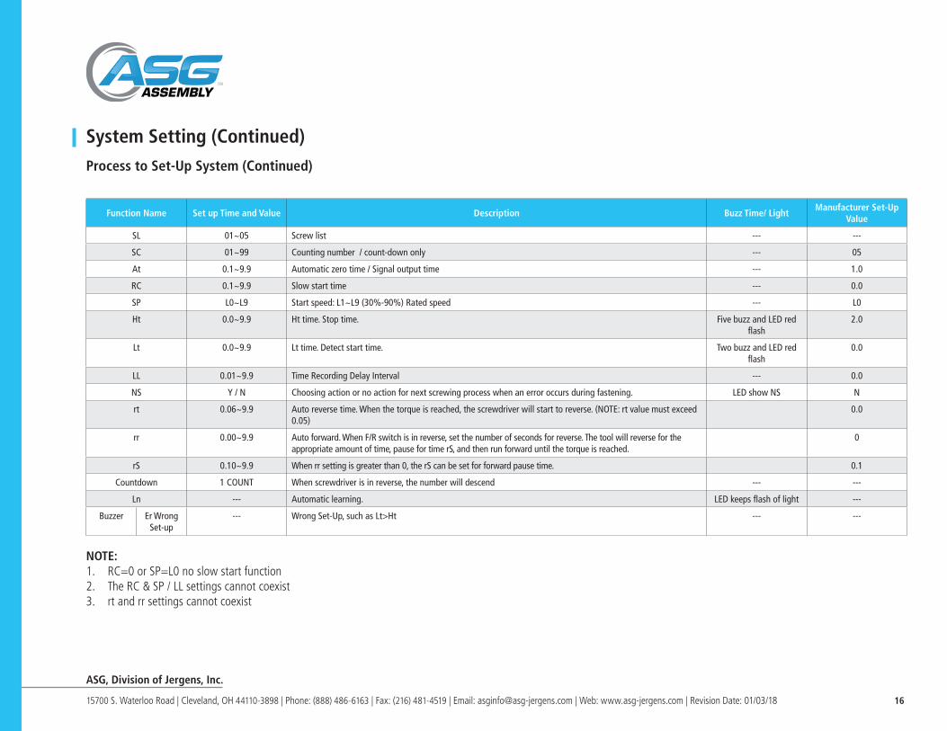
NOTE: 1. RC=0 or SP=L0 no slow start function2. The RC & SP / LL settings cannot coexist3. rt and rr settings cannot coexist
Function Name Set up Time and Value Description Buzz Time/ LightManufacturer Set-Up
Value
SL 01~05 Screw list --- ---
SC 01~99 Counting number / count-down only --- 05
At 0.1~9.9 Automatic zero time / Signal output time --- 1.0
RC 0.1~9.9 Slow start time --- 0.0
SP L0~L9 Start speed: L1~L9 (30%-90%) Rated speed --- L0
Ht 0.0~9.9 Ht time. Stop time. Five buzz and LED red flash
2.0
Lt 0.0~9.9 Lt time. Detect start time. Two buzz and LED red flash
0.0
LL 0.01~9.9 Time Recording Delay Interval --- 0.0
NS Y / N Choosing action or no action for next screwing process when an error occurs during fastening. LED show NS N
rt 0.06~9.9 Auto reverse time. When the torque is reached, the screwdriver will start to reverse. (NOTE: rt value must exceed 0.05)
0.0
rr 0.00~9.9 Auto forward. When F/R switch is in reverse, set the number of seconds for reverse. The tool will reverse for the appropriate amount of time, pause for time rS, and then run forward until the torque is reached.
0
rS 0.10~9.9 When rr setting is greater than 0, the rS can be set for forward pause time. 0.1
Countdown 1 COUNT When screwdriver is in reverse, the number will descend --- ---
Ln --- Automatic learning. LED keeps flash of light ---
Buzzer Er Wrong Set-up
--- Wrong Set-Up, such as Lt>Ht --- ---
ASG, Division of Jergens, Inc.
15700 S. Waterloo Road | Cleveland, OH 44110-3898 | Phone: (888) 486-6163 | Fax: (216) 481-4519 | Email: [email protected] | Web: www.asg-jergens.com | Revision Date: 01/03/18 17
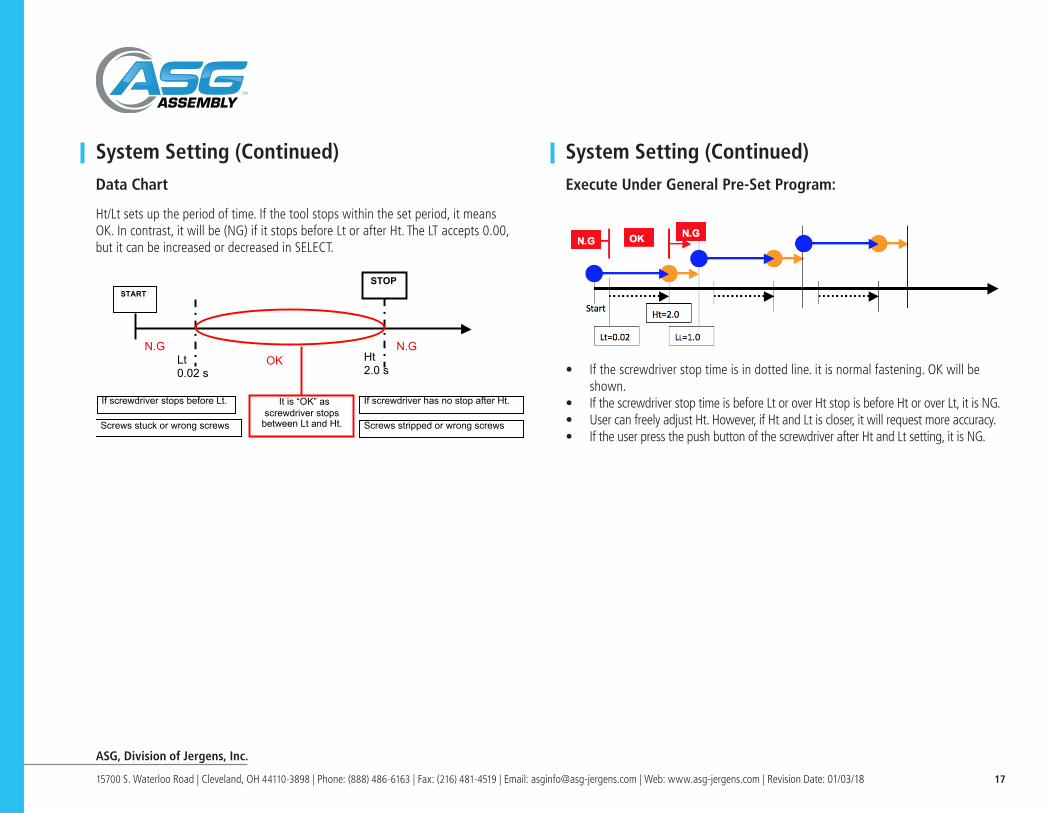
System Setting (Continued) Data Chart
Ht/Lt sets up the period of time. If the tool stops within the set period, it meansOK. In contrast, it will be (NG) if it stops before Lt or after Ht. The LT accepts 0.00,but it can be increased or decreased in SELECT.
STOP
Lt 0.02 s
Ht 2.0 s
If screwdriver stops before Lt. If screwdriver has no stop after Ht.
N.G
It is “OK” as screwdriver stops
between Lt and Ht. Screws stuck or wrong screws Screws stripped or wrong screws
N.G OK
START
System Setting (Continued) Execute Under General Pre-Set Program:
• If the screwdriver stop time is in dotted line. it is normal fastening. OK will be shown.
• If the screwdriver stop time is before Lt or over Ht stop is before Ht or over Lt, it is NG.• User can freely adjust Ht. However, if Ht and Lt is closer, it will request more accuracy.• If the user press the push button of the screwdriver after Ht and Lt setting, it is NG.

ASG, Division of Jergens, Inc.
15700 S. Waterloo Road | Cleveland, OH 44110-3898 | Phone: (888) 486-6163 | Fax: (216) 481-4519 | Email: [email protected] | Web: www.asg-jergens.com | Revision Date: 01/03/18 18
Simulated Learning1. The switch mode SW5 change into ON.
• When SW5 switch is ON, it enters the simulated learning procedure and functions will not work.
2. LED will flash when it is ON. The user can set whether or not to count screws or whether or not to use the slow-start function.
3. When set-up is finished, the LED will show 0.0 and the user can begin to fasten screws. When the screwdriver starts, the LED will show the count. User can test until satisfied. If the user changes the SW5 switch to OFF, the system will set up Ht time automatically. (Note: Lt will be set to zero)
4. Alternatively, the user can change SW5 to OFF, push SELECT for three seconds, then enter menu to change.
System Procedure
GroundingWhen use the power supply, it should be grounded to avoid operator getting electrical shock. This power supply is equipped with 3 leading wires and 3 pins of grounding plug to fit for grounding type of outlet. The grounding wire must be connected firmly with power supply equipment for effective grounding result. The leading wire with yellow-green color is a grounding wire. Never attempt to connect this yellow-green color wire on electrified connector, this power supply has built-in grounding wire with electric leakage safety grounding and additionally, the power supply can eliminate ESD static, which is produced by running the electric screwdriver, via grounding wire.
Servicing• Do not use the tool more than 8 hours a day.
• Do not let the motor and power supply get over heated. Do not run more than 10-15 screws/minute.
• If you use the tool more than 8 hours a day, have the tool evaluated for preventative maintenance.
• Inspect tool cords periodically. If damaged, contact ASG.
• Do not remove any labels.
Using non-ASG replacement parts may result in decreased tool performance and increased maintenance and may void all warranties. All repairs and maintenance of this tool must be performed by ASGASG is not responsible for customer modification of tools for applications on which ASG was not consulted.It is the responsibility of the employer to place the information in this manual into the hands of the operator.
PLEASE NOTE: When repairing or replacing tools or components on any TLB Series purchased in 2016 or prior, please contact ASG representative

ASG, Division of Jergens, Inc.
15700 S. Waterloo Road | Cleveland, OH 44110-3898 | Phone: (888) 486-6163 | Fax: (216) 481-4519 | Email: [email protected] | Web: www.asg-jergens.com | Revision Date: 01/03/18 19
WarrantyThe warranty is 1 year after delivery. If any troubles should occur, please contact ASG. In the following cases, the purchaser shall pay for parts and labor regardless of the terms of warranty:
• Failure due to improper handling.• Failure due to product modification or improper processing.• Failure due to causes beyond control (for example earthquake or fire).• Consumables, replaceable parts, and replacement work expenses.
DO NOT ATTEMPT TO REPAIR THIS ELECTRIC SCREWDRIVERSAVE THESE INSTRUCTIONS - DO NOT DESTROY