tl asp aircraft batteries maintenance d0_ 2009
TRANSCRIPT

NICKEL – CADMIUM AIRCRAFT BATTERIES ( SAFETY + POWER )
MAINTENANCE AND OVERHAUL MANUAL
Document no : TL ASP 001 Date of issue : May 1998 Change : 2 Date of change : June 2009

2
Table of contents
Section Page Section Page 1. Description and design 3 8. Battery rooms 15
General 1.1 Application 3 9. Trouble finding and corrective action 16 1.2 Battery 3 1.3 Cell – electrodes, separator, cell container, 3 10. Technical data for aircraft batteries 17 Vent, connectors, electrolyte 1.4 Description of design and operation 5 11. Battery process card 18 2. Safety measures and safety instructions 5 12. Assembly illustrations and wiring diagrams
2.1 Remarks and warnings 5 F20/15H1C 19 2.2 Safety instructions 5 F20/15H1C-2 20 F20/22H1C-1 21 3. Technical data for aircraft batteries 6 F20/25H1C-R 22
3.1 General: Definitions of the rated capacity 6 F20/27H1C-M 23 3.2 Technical data 7 F20/25H1CTF 24 F20/40H1C 25 4. Installation of the battery and initial charging 7 F20/40H1CE1 WTH 26
4.1 Battery process card 7 F20/40H1CE1 WT 27 4.2 Installation of the battery 7 F20/40H1CTF
F20/25H1C-L39 28 29
4.3 Fitting in the aircraft 8 13. ANNEXES 5. Maintenance 8 ANNEX A 30
5.1 Maintenance intervals 8 ANNEX B 31 5.2 Visual Inspection 9 5.3 Electrical check 9 14. UL-10 Charger / discharger 32 5.3.1 Charging with constant current 9 5.3.1.1 Maintenance charging with time controlled 9 Figures and tables Page recharging
5.3.1.2 Constant current charging with I5 10 Fig-1 Batteries 3 5.3.2 Capacity test 10 Fig-2 Cell 4 5.3.3 Evaluation of the test results 10 Table-1 Technical data 7 5.3.4 Electrolyte level check 11 Fig-3 Dependence of cell voltage on temperature 8 5.3.5 Cleaning 11 Fig-4 Current and voltage curve of a Ni-Cd cell in 10 maintenance charging 6. General checking and overhaul 12 Fig-5 Typical voltage curve when charging a cell constant 10
6.1 Period of overhaul 12 current I5 6.2 Battery process card 12 Fig-6 Typical voltage curve when discharging a Ni-Cd cell 10 6.3 Measures prior to the battery being 12 with the constant current 5xI5 dismantled Fig-7 Typical voltage curve when charging a cell with the 11 6.4 Dismantling the battery 12 separator damaged 6.5 Checking the parts when dismantled 12 Fig-8 Elmwood test method 14 6.6 Replacing the dismantled parts 13 Table-2 Technical data 17 6.7 Cleaning the dismantled parts 13 Table-3 Battery process card 18 6.8 Assembly 13 Fig-9 UL-10 Charger / discharger device 31 6.9 Test after assembly 13 6.9.1 Electrical checking 13 6.9.2 Insulation test 13 6.10 Testing the temperature sensors 13 6.10.1 Testing intervals 13 6.10.2 Testing procedure 14 7. Storage and Shipment 15 7.1 Storage period 15 7.2 Storage conditions 15

3
1. Description and design
1.1 Application
Both large medium sized airliners and small sporting aircraft’s need a reliable storage battery to ensure the safety of flying operations. In the event of the airborne supply system failing, the battery must be capable of providing adequate power for the radio, navigation, control and monitoring systems. What is more, the battery must supply the energy required to start the aircraft engines.
1.2 Battery
The battery is generally made up of 20 cells, which are incorporated in a battery case. The battery container and cover as well as all hardware are made of stainless steel sheet. The interior of the battery container is lined with heat resistant plastic plates. The cover is lined with soft rubber ribbing, which acts as a pressure pad for the cells. The battery is vented bay means of tubes attached to the side of the battery. A plug mounted on the front of the battery to airborne supply system. All batteries can be additionally fitted with temperature sensors for thermal monitoring.
Figure – 1 Batteries
1.3 Cell
The cell is the basic component of the nickel-cadmium battery-as is the case with other accumulators.
The ‘’Safety Plus Power’’ cell marked with a ‘’C’’ is a further developed cell, ensuring even more safety and reliability in flying operations.
Optically the ‘’Safety Plus Power’’ cells are indicated by the yellow colour of the cell-lid.
It comprises positive and negative electrodes in sinter-plate design, consisting of separators, electrolyte, cell container and a vent.

4
Electrodes
A sintered metallic structure serves as a composite carrier for the negative and positive electrodes, comprising nickel powder with a porosity of about 80%. This structure is stiffened by means of perforated, nickel-plated metal insert. The active material is introduced into highly porous composite carrier in a liquid state. Here the positive electrodes are immersed in a nickel solution, and the negative electrodes in cadmium solution.
Separators
Special, extremely thin separators prevent contact between the negative and positive electrodes.
Plate pack
Separators are alternately placed between the positive and negative electrodes to produce a plate pack with corresponding end terminals.
Figure – 2 Cell
Cell container
The cell container and cell cover are made of heatresistant plastic (polyamide). Once the plate pack has been inserted, the container and cover are sealed together to form an airtight unit by a special process.
Vent
Each cell is closed with a special vent which ensures that the gasses produced during charging are able to escape when a certain pressure has been reached, which, in turn, prevents electrolyte leakage when the battery is turned upside down.
Connectors
Good conducting nickel-plated copper connectors are used for intercell connections.
5
Electrolyte
The electrolyte, a solution of potassium hydroxide (KOH) and distilled water with a density of 1.28kg/I + 0.2kg/I at 20°C,is used in this battery. The purity of electrolyte corresponds to the specification according to VDE 05100. The composition of the battery should fall in line with the instructions of the battery manufacturers.
1.4 Description of Design and operation
(Procedures during charging and discharging)
The electrochemical procedures for charging and discharging are as follows: pos. electrode neg. electrode pos. electrode neg. electrode 2 Ni (OH)2 + Cd (OH)2 2 NiO (OH) + Cd + 2 H2O charging
discharging The electrolyte caustic potash (KOH) is itself untouched by these reactions, only serving as a current conductor between the positive and negative plates. The specific gravity of the electrolyte, thus, does not undergo any changes in contrast to a lead acidic battery.
Remarks
This is the reason why the electrolyte density is no criterion for the battery’s state of charge.
2.Safety measures and safety instructions
2.1 Remarks and warnings
Remarks and warnings in this manual appear as follows:
Caution !
This headline applies where non-adherence or incorrect adherence to the service or working instructions could cause injuries or fatal accidents.
Attention !
This headline applies where non-adherence or incorrect adherence to the service or working instructions might cause damage to the unit.
Remarks
This headline is used to call attention to important points.
2.2 Safety Instructions
COUTION !
Never use flames or glowing matter in the vicinity of the battery.
The caustic potash solution is corrosive ! Avoid any contact with the eyes, open wounds or skin and clothing. Observe the accident prevention instructions.
Wear rubber gloves and protective goggles when working with electrolyte. Protective clothing is recommended.
For ‘’First Aid’’, in case of burns, rinse copiously with water and consult a doctor immediately.
Never use metal brushes or brushes with metal supports.
Electrical shorts may cause injuries and lead to the battery being damaged.
Never place any live parts on the battery.
6
If the cells are blown off with compressed air, keep the vent plugs fitted and be sure to wear protective goggles.
Use only a plastic wrench for screwing the vent plugs on and off. Do not repair defective vents.
Never use tools previously used for lead batteries.
Only use distilled water according to VDE 0510.
ATTENTION !
General checking and overhaul of the batteries must only be carried out by trained specialists.
3. Technical data for aircraft batteries
General
3.1 Definition of the rated capacity
As a battery parameter the rated capacity is based on a specified discharge at a certain temperature up to a stipulated final discharging voltage.
The following is used with open nickel cadmium batteries:
- 5-hour constant discharging current
- 20°C battery temperature
- Final discharging voltage: 1.0V times the number of in line cells.
The rated capacity is designated as C5 and is specified in ampere hours (Ah). The 5-hour discharging current is designated as I5.
The discharging current I5 with rated current is designated according to the rated capacity C5.
The rated current I5 is calculated from the rated capacity C5 as follows:
I5 = C5 (Ah) = 0,2 C5 (A) 5 (h)
Example: Nickel cadmium battery 24 V 40 Ah
C5 = 40 Ah I5 = 40 Ah = 0,2 C5 (A) = 8 A 5 h
Additionally the 1 hrs capacity (see section 3.2) is defined by C1
- Al batteries can be provided with temperature monitoring when required.
- The letter ‘’T’’ in the VARTA type designation distinguishes batteries with temperature sensors or temperature switches. The number after to letter ‘’T’’ indicates the number
- All values for capacities, voltage and specific gravity are based on a nominal temperature of the electrolyte of 20˚C.
Attention
It is not allowed to connect different-type cells in one battery group.
7
Battery process card
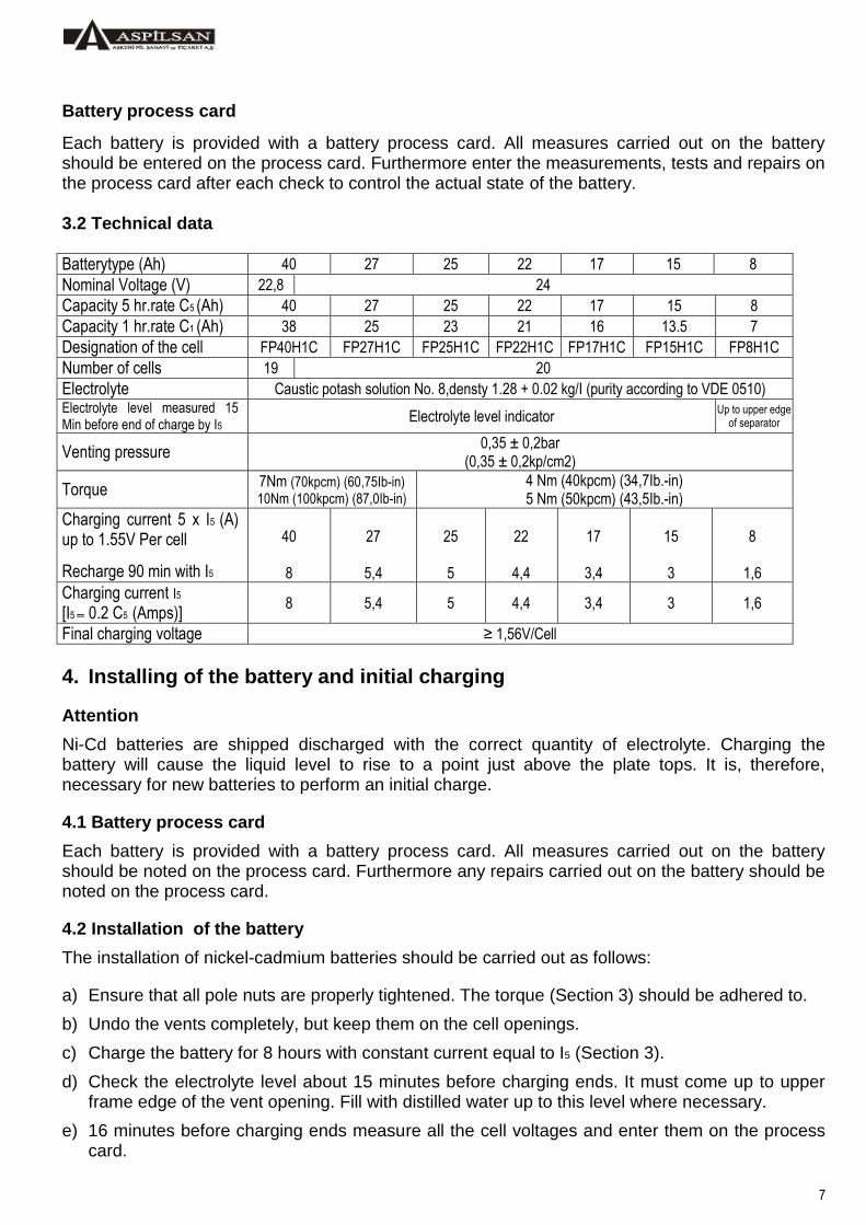
Each battery is provided with a battery process card. All measures carried out on the battery should be entered on the process card. Furthermore enter the measurements, tests and repairs on the process card after each check to control the actual state of the battery. 3.2 Technical data
Batterytype (Ah) 40 27 25 22 17 15 8
Nominal Voltage (V) 22,8 24
Capacity 5 hr.rate C5 (Ah) 40 27 25 22 17 15 8
Capacity 1 hr.rate C1 (Ah) 38 25 23 21 16 13.5 7
Designation of the cell FP40H1C FP27H1C FP25H1C FP22H1C FP17H1C FP15H1C FP8H1C
Number of cells 19 20
Electrolyte Caustic potash solution No. 8,densty 1.28 + 0.02 kg/I (purity according to VDE 0510) Electrolyte level measured 15 Min before end of charge by I5
Electrolyte level indicator Up to upper edge
of separator
Venting pressure 0,35 ± 0,2bar
(0,35 ± 0,2kp/cm2)
Torque 7Nm (70kpcm) (60,75Ib-in) 10Nm (100kpcm) (87,0Ib-in)
4 Nm (40kpcm) (34,7Ib.-in) 5 Nm (50kpcm) (43,5Ib.-in)
Charging current 5 x I5 (A) up to 1.55V Per cell
Recharge 90 min with I5
40
8
27
5,4
25
5
22
4,4
17
3,4
15
3
8
1,6
Charging current I5
[I5 0.2 C5 (Amps)] 8 5,4 5 4,4 3,4 3 1,6
Final charging voltage ≥ 1,56V/Cell
4. Installing of the battery and initial charging
Attention
Ni-Cd batteries are shipped discharged with the correct quantity of electrolyte. Charging the battery will cause the liquid level to rise to a point just above the plate tops. It is, therefore, necessary for new batteries to perform an initial charge.
4.1 Battery process card
Each battery is provided with a battery process card. All measures carried out on the battery should be noted on the process card. Furthermore any repairs carried out on the battery should be noted on the process card.
4.2 Installation of the battery
The installation of nickel-cadmium batteries should be carried out as follows:
a) Ensure that all pole nuts are properly tightened. The torque (Section 3) should be adhered to.
b) Undo the vents completely, but keep them on the cell openings.
c) Charge the battery for 8 hours with constant current equal to I5 (Section 3).
d) Check the electrolyte level about 15 minutes before charging ends. It must come up to upper frame edge of the vent opening. Fill with distilled water up to this level where necessary.
e) 16 minutes before charging ends measure all the cell voltages and enter them on the process card.

8
Attention
All cell voltages must be greater than 1.56V. f) Allow the battery to stand for 1hour to permit charging gases to escape.
g) Tighten up vents.
4.3 Fitting in the aircraft
Once all these conditions are met, the battery can be fitted in the air craft. Attention It is important for the service life and the proper operation of the battery, that the aircraft electrical supply system be main at the correct level, with respect to temperature, in case of over voltage there may be gassing and electrolyte leakage. At a regular temperature in the 15°C to 30°C range the voltage should be set between 1,40 V and 1,425 V per cell (28 V and 28,5 V for 20 cell battery, 26,6 V and 27,0 V for 19 cell battery).
For higher temperatures the airborne supply voltage must be reduced to 1.36 V to 1.375 V Per cell.
Figure – 3 Dependence of cell voltage against temperature.
5. Maintenance
Battery process card
Each battery is provided with a battery process card. All measurements carried out on the battery should be noted on the process card. Furthermore enter all repairs after any maintenance and repair work to the batteries on the process card.
Remarks
Maintenance is to be carried out in an air-conditioned room at 15°C to 30°C.
5.1 Maintenance intervals
a) A visual inspection of the battery in the aircraft should be made at least once every 100 flight hours or once every four weeks. The battery must be moved to enable the cell cover to be opened. The battery connectors, terminals. Plugs, vents, etc. Should be checked for contact-failure, damage and corrosion.
If excessive carbonate deposits and electrolyte leakage, damage or wetness is encountered, the battery must be workshop inspected.
b) The battery should be maintained once every 300 flight or once every 3 months. The battery should be removed and taken to the workshop.
c) General checking and overhauling are necessary once a year. Here the battery must be removed from the aircraft, taken to the workshop and disassembled.

9
5.2 Visual inspection
Attention
If defects or damage are ascertained during visual inspection, the battery should be repaired according Sections 5 and 6.
The visual inspection on the battery should be carried out as follows:
- Check all cells and plastic parts for damage caused by overheating
- Check terminals, nuts and cell connectors for corrosion
- Check for carbonate deposits and electrolyte leakage.
- Check the ventilation pipes for damage and obstruction
- Check the battery container and cover for damage
- Check the vent plugs are tight and free of cracks
- Check for damage to the sockets
- Check for mechanical damage to temperature monitoring and damage by electrolyte crystals.
5.3 Electrical check
5.3.1 Charging with constant current
Attention !
Prior to charging, the battery must be treated as follows;
- Ensure that all pole nuts are properly tightened. The Torque must be carefully observed (see section 3).
- Undo the vents completely, but leave them on the cell opening.
- Adjust the electrolyte level of the cells with distilled water up to the top edge of separator.
- Batteries must be discharged completely.
- Discharge the battery with a constant current of 5 x I5 to remove residual capacity (see section 3) until a final discharge voltage of 1,0V is reached multiplied by the number of in-line cells.
5.3.1.1 Maintenance charging with time controlled recharging
The battery is charged with a 5 x I5 current until the battery voltage has reached 1,55V multiplied by the number of cells (i.e. 31V for 20 cells). The battery is then charged with the constant current of I5 for 90minutes (for charging data see section 3). Attention !
Take care to ensure that the checks are made;
a) Electrolyte levelling should be carried out according to 5.3.4 15 minutes before the end of charging.
b) Then measure all cell voltages (final charging voltage) and enter them on the process card. The final charging voltage of all cells must be greater than 1,56V.
c) After charging, allow the battery to stand for 1hour to permit any charging gas to escape.
d) Tighten the vents.

10
I – Charge additional charge Figure – 4 Current and voltage curve of a Ni-Cd cell with maintenance charging.
Figure – 5 Typical voltage curve when charging a cell constant current I5
5.3.1.2 Constant current charging with I5
Charge the battery with constant current I5 for 7hours (for charging data see section 3).
Attention !
a) Electrolyte levelling should be carried out according to 5.3.4 15 minutes before the end of charging.
b) Then measure all cell voltages (final charging voltage) and enter them on the process card. The final charging voltage of all cells must be greater than 1,56V.
c) After charging, allow the battery to stand for 1hour to permit any charging gas to escape.
d) Tighten the vents.
5.3.2 Capacity test
Discharge the battery with a constant current of 5 x I5 (see section 3) until a final discharging voltage of 1,0V multiplied by the number of in-line cells is reached.
Measure the cell voltages 48minutes after discharging has started and enter them on the battery process card.
After the capacity test recharge the battery according to 5.3.1.1 or 5.3.1.2 with the corresponding check steps.
Figure – 6 Typical voltage curve with discharging a Ni-Cd cell with constant current 5 x I5
5.3.3 Evaluation of the test result
A. The battery is in order and can be returned to the aircraft, if:
a) Capacity C5 is greater than 80% of the rated capacity.
b) 15minutes before the end of charging all cell voltages must be greater than 1,56V.
B. The battery is to be checked, if the conditions under a or b not met.

11
Mark any defective cells and treat as under 6.6
Figure – 7 Typical charge voltage
Characteristic of a cell with a
Damaged separator.
5.3.4 Electrolyte level check
Attention !
- Generally, check the electrolyte level 15minutes before end of charging
- The electrolyte level can only be regulated with I5 charging.
- Single cell can only be regulated when installed.
- Only fill up with distilled water according to DIN 0510 (conductivity should be less than 3µs).
- Never use sulphuric acid or acidified water. Any acid will destroy Ni-Cd batteries.
- Open vents carefully
- If the electrolyte level is too high, siphon some off.
- If the electrolyte level is too low, add distilled water according to DIN 0510 up to the level prescribed in section 3.
Attention !
The caustic solution of potassium hydroxide is highly corrosive. Always use protective goggles and rubber gloves.
5.3.5 Cleaning
Keep the battery clean and dry. It is not necessary to dismantle the battery for cleaning purposes. Remove deposits on the cell covers, pole bolts and the connectors with a soft cloth, compressed air or plastic brush.
Remark
- The simplest and the fastest way of cleaning the cell cover is to blow off any deposits or dirt with a air hose.
- Unscrew vents with carbonate deposits from the cells and clean them in warm water (about 55ºC) with plastic brush.
- If there is an electrolyte leakage, clean the battery according to 6.7
Attention !
- Always wear protective goggles.
- Do not allow plastic parts come into contact with oil, grease or solvent,
- Bare cell parts, such as connectors, pole nuts and bolts, should be lightly sprayed with baysilone.

12
6. General checking and overhaul Remarks
General checking should only be carried out:
1. When defect cells are being exchanged.
2. With serious leakage of caustic potash solution and extreme contamination.
3. If the final charging voltage of 1.56V/cell has not been reached.
4. When the battery overheats.
6.1 Period of overhaul
The battery must be generally overhauled after 12 mounts.
6.2 Battery process card
All reconditioning work and replacement of parts are to be entered on the battery process card.
6.3 Measures prior to the battery being dismantled
Discharge the battery with the constant current 5 x I5 or I5 (see section 3) until all cell voltages drop to max. of 0,5V. During this discharging process the polarity of individual cells may be reversed, but this is of no significance.
6.4 Dismantling the battery
Only dismantle the battery as required for checking (see paragraph 14)
Attention !
Do not loosen lower pole nuts.
a) Using an appropriately sized socked wrench undo the upper pole nuts of the cells and remove them from the positive and negative end poles with the washers and connectors (Z-connectors).
The lower pole nuts with check caps and sealing rings remain on the end poles.
b) Remove the temperature sensors, but leave them as one unit.
c) To dismantle the sockets remove the connectors with the attachment parts and the sealing rings from the battery container.
d) Using the socked wrench first remove one cell from the middle of the battery, then take out the rest from the battery container.
e) Remove the insulation liner from the battery container.
6.5 Checking the parts when dismantled
a) Checking the battery container and cover for any mechanical damage, such as scratches, dents, cracks.
b) Check the plug connection for any mechanical or thermal damage.
c) Check the washers for wear.
d) Make sure the battery liner is complete and fits correctly.
e) Check the cells for leakage and thermal damage.
f) Check the cell connectors, nuts, Washers and pole bolts for corrosion, mechanical and thermal damage.
g) Check the temperature monitoring unit for mechanical damage and temperature function.
h) Check the vents for mechanical damage and function.
13
6.6 Replacing the dismantled parts
- Replace defective cells.
Attention !
Do not repair defective vents, but replace them by new ones.
6.7 Cleaning the dismantled parts
Caution !
Tighten the vents before cleaning the cells.
Attention !
a) Do not allow plastic parts to come into contact with oil, grease or solvents.
b) Rinse the parts thoroughly in warm water, Use a soap solution, cloth and plastic brush for cleaning.
c) Rinse the parts in clear water, rub them dry and allow the subsequently to dry in the air.
d) Bare cell parts, such as connectors, pole nuts and bolts should be lightly sprayed with Baysilone (see Section 12.2).
6.8 Assembly
Attention !
It is inadmissible to connect cells different types or with different capacities in one battery group.
Only use discharged cells.
When inserting the cells do not hammer them into position. Undo the vent plugs to facilitate easier cell assembly.
Take care to ensure that the battery liner does not cover the vent openings in the battery container.
Carry out assembly in the reverse order of dismantling.
Please observe the following:
a) Tighten the lower poles of the cells with the corresponding torque (see Section 3).
b) Refer to the pertinent wiring diagram for interconnecting the cells (see paragraph Section 14).
c) Tighten the upper pole nuts with the corresponding torque (see Section 3).
d) After assembly repair the coating of Baysilone on the bare cell parts where necessary.
6.9 Test after assembly
6.9.1 Electrical checking
Carry out electrical checking according to 5.3.
6.9.2 Insulating test
Connect a high voltage tester between the positive or negative terminal and the battery case, applying a test voltage of 2.5kV If the tester gives the signal for insufficient insulation at a current over 18mA then dismantle and clean the battery as detailed in section 6.4. Other Insulation tester also can be used. For example using the Megga tester the test voltage is 250V and the insulation resistance of 15 kΩ is the limiting value, below which the battery shall be dismantled and cleaned.
14
6.10 Testing the temperature sensors
6.10.1 Testing intervals
The temperature switches (bimetal thermostats) must be tested at 4-year intervals.
This test can be carried out by the aircraft user or battery manufacturer. Alternatively, the complete temperature monitoring unit can be replaced.
Attention !
Be sure to enter the check and/or replacement of the temperature monitoring unit on the battery process card.
6.10.2 Testing procedure
Attention !
Do not disconnect the connectors from the temperature switch. The connector with the temperature switch is attached to a heatable fixture. A measuring instrument (ohmmeter) is connected between the relevant terminals of the temperature switch for checking the switching functions. The temperature of the heatable fixture is increased slowly to the upper switching temperature pertinent to the temperature switch (≈ 1°C). The temperature of the heatable fixture is then lowered to the lower switching temperature pertinent to the temperature switch.
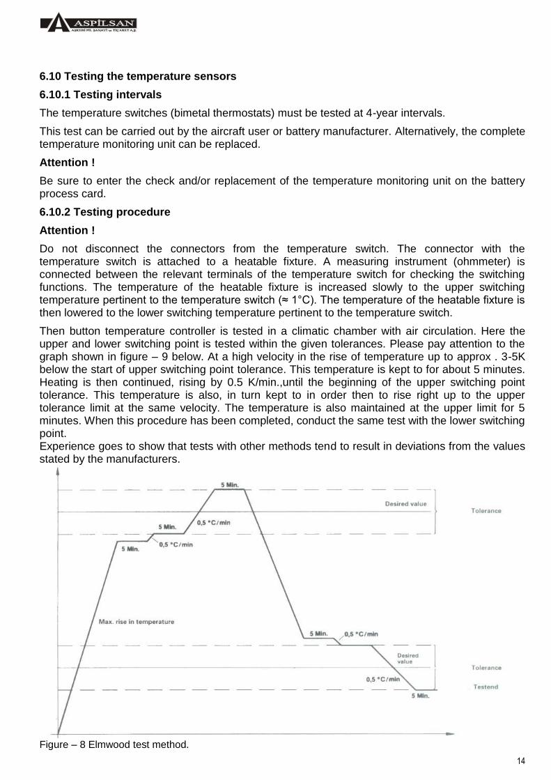
Then button temperature controller is tested in a climatic chamber with air circulation. Here the upper and lower switching point is tested within the given tolerances. Please pay attention to the graph shown in figure – 9 below. At a high velocity in the rise of temperature up to approx . 3-5K below the start of upper switching point tolerance. This temperature is kept to for about 5 minutes. Heating is then continued, rising by 0.5 K/min.,until the beginning of the upper switching point tolerance. This temperature is also, in turn kept to in order then to rise right up to the upper tolerance limit at the same velocity. The temperature is also maintained at the upper limit for 5 minutes. When this procedure has been completed, conduct the same test with the lower switching point. Experience goes to show that tests with other methods tend to result in deviations from the values stated by the manufacturers.
Figure – 8 Elmwood test method.
15
7. Storage and shipment
7.1 Storage period
The storage period is 5 years provided that the storage conditions indicated in paragraph 7.2 are observed. After this period of storage, batteries should be checked according to paragraph 5.3. and the storage period can be extended for 2 additional years from 5th and7th year and for 1 year from 9th year if the electrical capacity is determined more than %80 of nominal capacity. However, the overall storage life should be limited to 10 years maximum.
All metallic parts can be stored for an unlimited length of time under the conditions mentioned in paragraph 7.2.
7.2 Storage conditions
The battery and/or cell must be stored upright, filled and discharged.
Attention !
a) Stored batteries must be protected from dirt, dust, moisture, aggressive gases, especially acidic fumes.
b) Batteries must be stored in a cool, well aired room. The storage temperature should be between +10°C and +35°C and the relative air humidity between 45% and 75%.
c) Lead batteries shall not be stored in the same room
All metal parts can be stored for an unlimited length of time under the above-mentioned conditions.
For batteries that have been stored for 5 years check them as described under Section 5.
8. Battery rooms
The rooms must be dry, and well ventilated. They must also be easily accessible and protected against vibrations and fluctuations in temperature. The walls of the rooms should be at least 2 metres high.
Attention !
The operating temperature must be between +10°C and +35°C.
Attention !
Take good care to ensure that dust or noxious gases and vapours do not enter.
Attention !
Lead batteries may only stored in the same room with nickel cadmium batteries, if it is ensured that any sulphuric acid fumes from the lead batteries cannot come into contact with the nickel cadmium batteries.
Where possible the battery rooms should be so that the batteries can be installed easily and well arranged for immediate access. Ventilation should not be hindered in any way.
General requirements: The walls, floors and ceilings must be protected from the effects of the electrolyte, the same applying to trough pipelines, in as much as this cannot be avoided. Heating pipes must be insulated, if too high temperature is produced by them.
Doors to battery rooms should open outwards and have a warning sign on the outside to the effect ‘’No smoking’’, ‘’No admittance’’, Work with open flame prohibited’’.
All electrical equipment in battery rooms such as cables, wires, plugs, must meat the stipulations VDE 0510 for ‘’moist and similar rooms.
Any electrical equipment, such as switches, wall plugs and lamps, must at least 1 metre away from the cells. If this is not possible, proceed according to VDE 0165.
The rooms must only be heatable, if the temperature is liable to drop to an unusually low level. Heating with open fire or radiator with a surface temperature greater than 200 °C is not admissible.

16
9. Trouble finding and corrective action
What’s the trouble Test step
What cause it Test procedure Corrective action
Battery shows dissimilar cell voltages.
1 2 3 4 5
Electrolyte level too low. Loose pole nuts. Socket burnt or damaged. Cell reversed in polarity. Cells without voltage
Measure electrolyte level. Check pole nuts with Torque wrench Check socket. Measure cell voltage. Measure cell voltage.
Correct electrolyte level according to 5.3.4. Tighten pole nuts. Clean the contacts or replace the socket. Discharge the battery according to 5.3.1.1 then make capacity test acc. to 5.3.2. Replace the cell.
One cell from one battery heats up very strongly.
1
Cell has less capacity Cell has short circuit. The cell’s charging condition is different from others.
Test capacity. Carry out electrical check 5.3. Replace cell.
Electrolyte leakage.
1 2 3
Leaky vents. Leaky cell container. Lower pole nut is loose.
Check the vents are tight or check the function. Check cell container. Check lower pole nut.
Tighten or replace vents. Replace leaky cells. Undo connector and tighten lower pole nut with Torque wrench.
Deformed battery case or cover.
1 Battery bolts too tight. Replace battery case or cover
Excessive carbonate deposits on the cells.
1 2
Electrolyte level too high. Charge voltage too high.
Check electrolyte level Check charge voltage.
Correct electrolyte level according to 5.3.4. Clean cell according to 5.3.5. Adjust voltage regulator.
Excessive carbonate deposits on temperature monitoring unit or crack in casting
1 Temperature effect too high
Check temperature monitoring unit according to 6.10.

17
10. Technical data for aircraft batteries
Technical Data
Battery type Specifications NSN
6140 27 ......
Cell type Nominal Peak
power (kW)
Dimensions (mm) Weight
(kg) Output
connector Application Voltage
(V) Capacity
(Ah) W L H
F20/8H1CT4
IEC952-1, IEC952-2, MIL-B-26220C, MIL-STD-810C, BS3G205, VG95238T2, TS EN 2570, TS 7300, AS 8033A, MS24496-2, MS24497-2, MS24498-2
005 8064 FP8H1C
24
8 5,9 142 315 123 10,5 MS 18093 MS 3509
Sikorsky UH-60 / S-70
F20/12H1CT - FP12H1C 12 9,2 211 230 162 13 Special F-16 Block 30
F20/15H1C 005 8062
FP15H1C 15 11,5
198 195 196 16,3
MS 18093 MS 3509
F-4, RF-5, Cessna 210
F20/15H1C-2 005 8063 209 270 146 16,3
AB-206, etc.
F20/15H1CT-2 -
F20/17H1C -
FP17H1C 17 11,8
198 195 196 16,7
F20/17H1C-2 - 209 270 146 16,7
F20/17H1CT-2 -
F20/17H1CT - FP17H1C 17 11,8 227 264 162 19
Special
F-16 Block 40/50
F20/22H1C-1 - FP22H1C 22 14 119 424 170 23,5 Special application
F20/22H1C-2 -
F20/25H1CTF 005 8061
FP25H1C 25 15,7
197 254 224 24,6 MS 18093 MS 3509
SF-260D, CASA C-212
20FP25H1C-R - 174 363 226 24,5
Special
TU-154/134, SU-22/24
F20/25H1C-L39 -- 430 207 240 26,5 Learjet-L39
F20/27H1CM 005 8060
FP27H1C 27 18,8 169 480 236 29
MI-8, MI-17
F20/27H1CM1 -
MI-8 / 24 F20/27H1CM2 -
F20/27H1CM3 -
F19/40H1C 007 8099
FP40H1C
22,5
40
21,3
247 253 262
35
MS 18093 MS 3509
C-130 Hercules
F20/40H1C 005 3805
24 22,5 36,5
C-160 TRANSAL, UH-1H, G-IV, CIT-7, B-212, T-37, MA-32A, Cessna Challenger etc.
F20/40H1CTF 005 8058 CASA CN-235
F20/40H1CE1WT(H) 005 8059 210 420 267 38 BAC 102 COUGAR AS-532
18
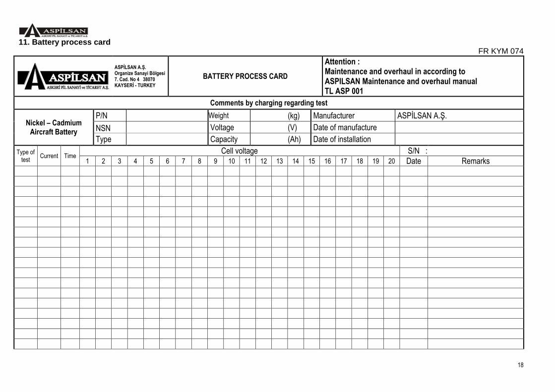
11. Battery process card FR KYM 074
ASPİLSAN A.Ş. Organize Sanayi Bölgesi 7. Cad. No 4 38070 KAYSERİ - TURKEY
BATTERY PROCESS CARD
Attention : Maintenance and overhaul in according to ASPILSAN Maintenance and overhaul manual TL ASP 001
Comments by charging regarding test
Nickel – Cadmium Aircraft Battery
P/N Weight (kg) Manufacturer ASPİLSAN A.Ş.
NSN Voltage (V) Date of manufacture
Type Capacity (Ah) Date of installation
Type of test
Current Time Cell voltage S/N :
1 2 3 4 5 6 7 8 9 10 11 12 13 14 15 16 17 18 19 20 Date Remarks

19
12. Assembly illustration and wiring diagram
Battery;
Type : F20/15H1C P/N : 60061200150 NSN : 6140 27 005 8062 Application : F-4, T-38, AB-206, etc.
Description Part no . 1- Battery container 15061150001 2- Battery lid 15061150002 3- Connector socket 15061150003 4- Sealing ring 15061900050 5- Sealing ring 15061900052 6- Slit counter screw 15061900051 7- Fan disc 15061900053 8- Cell type FP15H1C 60060200150 9- Hexagonal nut M8 15061900017 10- Spacer 15060150018 11- Sealing ring 15060150017 12- Vent plug 15060900001 13- Spring washer B8 15061900017 14- Connector D1 15061900006 15- Connector D4 15061900008 16- Connector D2 15061900007 17- Connector E1 15061900013 18- Connector E2 15061900014 19- Container empty 15061150004 20- Insulating material 15061150006
20
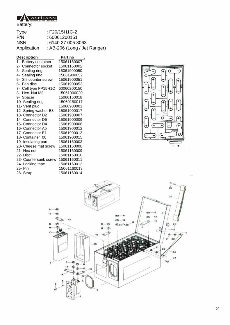
Battery;
Type : F20/15H1C-2 P/N : 60061200151 NSN : 6140 27 005 8063 Application : AB-206 (Long / Jet Ranger)
Description Part no . 1- Battery container 15061160007 2- Connector socket 15061160002 3- Sealing ring 15061900050 4- Sealing ring 15061900052 5- Slit counter screw 15061900051 6- Fan disc 15061900053 7- Cell type FP15H1C 60060200150 8- Hex. Nut M8 15061900020 9- Spacer 15060150018 10- Sealing ring 15060150017 11- Vent plug 15060900001 12- Spring washer B8 15061900017 13- Connector D2 15061900007 14- Connector D5 15061900009 15- Connector D4 15061900008 16- Connector A5 15061900012 17- Connector E1 15061900013 18- Container 00 15061900015 19- Insulating part 15061160003 20- Cheese mat screw 15061160008 21- Hex nut 15061160009 22- Discl 15061160010 23- Countersunk screw 15061160011 24- Locking tape 15061160012 25- Pin 15061160013 26- Strap 15061160014

21
Battery;
Type : F20/22H1C-1 P/N : 60061200220 NSN : ----- Application : Special
Description Part no . 1- Battery container 15061220001 2- Connector socket complete 15061220003 3- Cell FP22H1C complete 15386020220 4- Cell FP22H1C1 complete 15386020221 5- Vent plug 15060900001 6- Hex nut M8 15061900020 7- Spring washer B8 15061900017 8- Connector D1 15061900006 9- Connector D2 15061900007 10- Connector 15061900027 11- Connector long C1 15061900029 12- Insulating material complete 15061220004
22
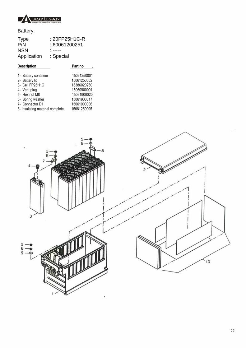
Battery;
Type : 20FP25H1C-R P/N : 60061200251 NSN : ----- Application : Special
Description Part no . 1- Battery container 15061250001 2- Battery lid 15061250002 3- Cell FP25H1C 15386020250 4- Vent plug 15060900001 5- Hex nut M8 15061900020 6- Spring washer 15061900017 7- Connector D1 15061900006 8- Insulating material complete 15061250005

23
Battery;
Type : F20/27H1C-M P/N : 60061200270 NSN : ----- Application : Special
Description Part no . 1- Battery container 15061270001 2- Battery lid 15061270002 3- Connector complete 15061270003 4- Tray 15061270004 5- Screw M5 15061270007 6- Washer B5,3 15061270008 7- Venting pipe 15061270009 8- Cell FP27H1C 15386020270 9- Vent plug 15060900002 10- Hex nut M10 15061900021 11- Spring washer B10 15061900018 12- Connector C1 15061900001 13- Connector C2 15061900002 14- Z-connector C4 15061900004 15- U profile 15061270006 16- Insulating material complete 15061270005

24
Battery;
Type : F20/25H1CTF P/N : 60061300250 NSN : 6140 27 005 8061 Application : SF-260D
Description Part no . 1- Battery container 15061250001 2- Battery lid 15061250002 3- Connector socket 15061250003 4- Sealing ring 15061900050 5- Sealing ring 15061900052 6- Slit counter screw 15061900051 7- Fan disc 15061900053 8- Cell type FP25H1C 60060200250 9- Hex. Nut M8 15061900020 10-Spacer 15060250017 11- Sealing ring 15060250016 12- Vent plug 15060900001 13- Spring washer B8 15061900017 14- Connector D1 15061900006 15- Connector D2 15061900007 16- Connector D5 15061900009 17- Connector D7 15061900010 18- Connector D8 15061900011 19- Container empty 15061250004 20- Temperature sensor 15061400008

25
Battery;
Type : F20/40H1C P/N : 60061200400 NSN : 6140 27 005 3805 Application : TRANSAL C-160, EC-2, AB-212, AB-205, UH-1H, MA32A, etc.
Description Part no . 1- Battery container 15061400001 2- Battery lid 15061400002 3- Connector socket 15061400003 4- Sealing ring 15061900050 5- Sealing ring 15061900052 6- Slit counter screw 15061900051 7- Fan disc 15061900053 8- Cell type FP40H1C 60060200400 9- Hex. Nut M10 15061900021 10-Spacer 15060400018 11- Sealing ring 15060400017 12- Vent plug 15060900002 13- Spring washer B10 15061900018 14- Connector C1 15061900001 15- Connector C3 15061900003 16- Connector C4 15061900004 17- Connector C5 15061900005 18- Connector C2 15061900002 19- Container empty 15061400005 20- Insulating material 15061400004

26
Battery;
Type : F20/40H1CE1 WTH P/N : 60061200401 NSN : 6140 14 518 2255 Application : COUGAR AS 532
Description Part no . 1- Battery container 15062400001 2- Battery lid 15062400002 3- Connector socket 15062400003 4- Slit counter screw 15061900051 5- Fan disc 15061900053 6- Cell type FP40H1C 60060200400 7- Hex. Nut M10 15061900021 8- Spacer 15060400018 9- Sealing ring 15060400017 10- Vent plug 15060900002 11- Spring washer B10 15061900018 12- Connector C1 15061900001 13- Connector C2 15061900002 14- Insulating material 15062400004
15- Temperature sensor 15062400008 *
16- Connector socket 15062400005 *
17- Thermal switches 15062400009 *
18- Heater 15062400007 *
See annex A for detail of wiring diagram

27
Battery;
Type : F20/40H1C E1 WT P/N : 60061200402 NSN : 6140 27 005 8059 Application : SUPER PUMA, COUGAR AS-532
Description Part no . 1- Battery container 15062400001 2- Battery lid 15062400002 3- Connector socket 15062400003 4- Slit counter screw 15061900051 5- Fan disc 15061900053 6- Cell type FP40H1C 60060200400 7- Hex. Nut M10 15061900021 8- Spacer 15060400018 9- Sealing ring 15060400017 10-Vent plug 15060900002 11-Spring washer B10 15061900018 12-Connector C1 15061900001 13-Connector C2 15061900002 14-Insulating material 15062400004
15-Temperature sensor 15062400008 *
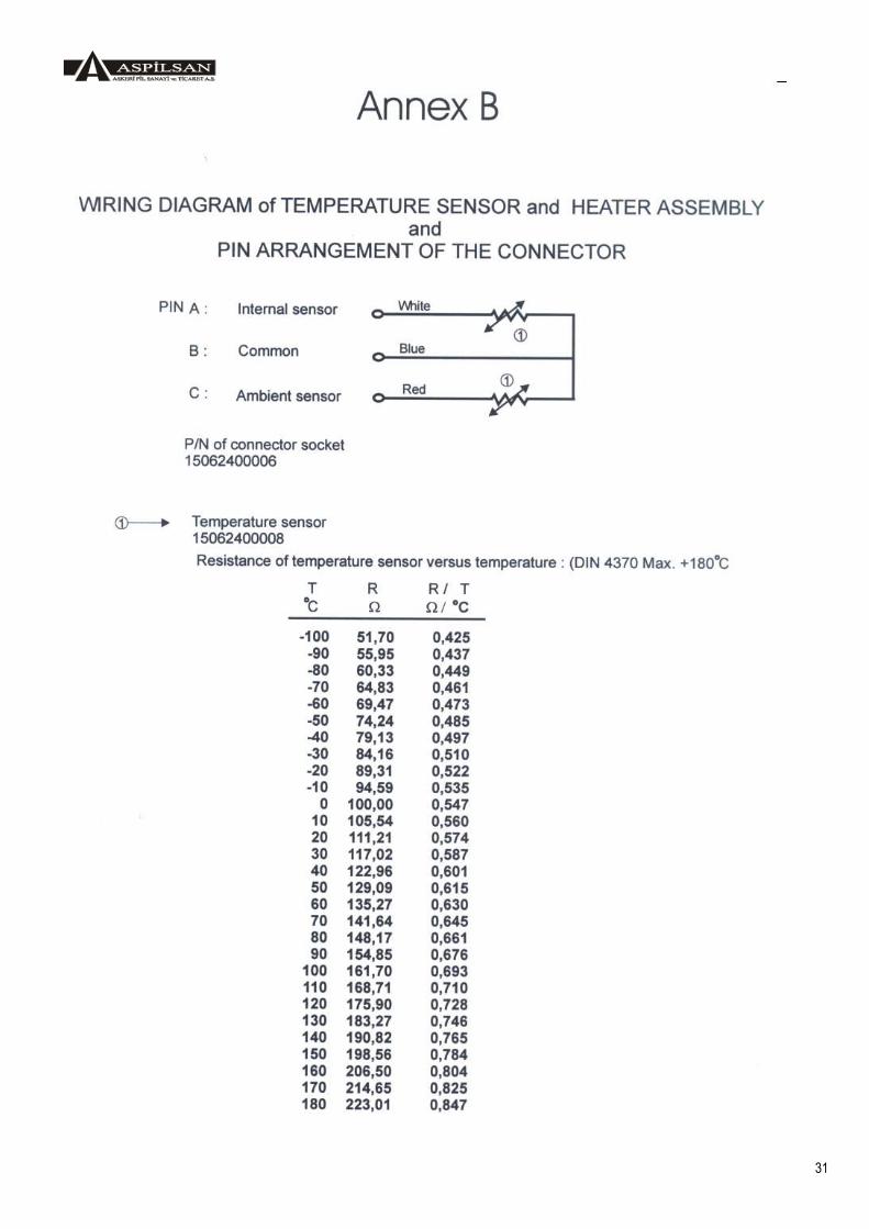
16-Connector socket 15062400006 * See Annex B for detail of wiring diagram
28
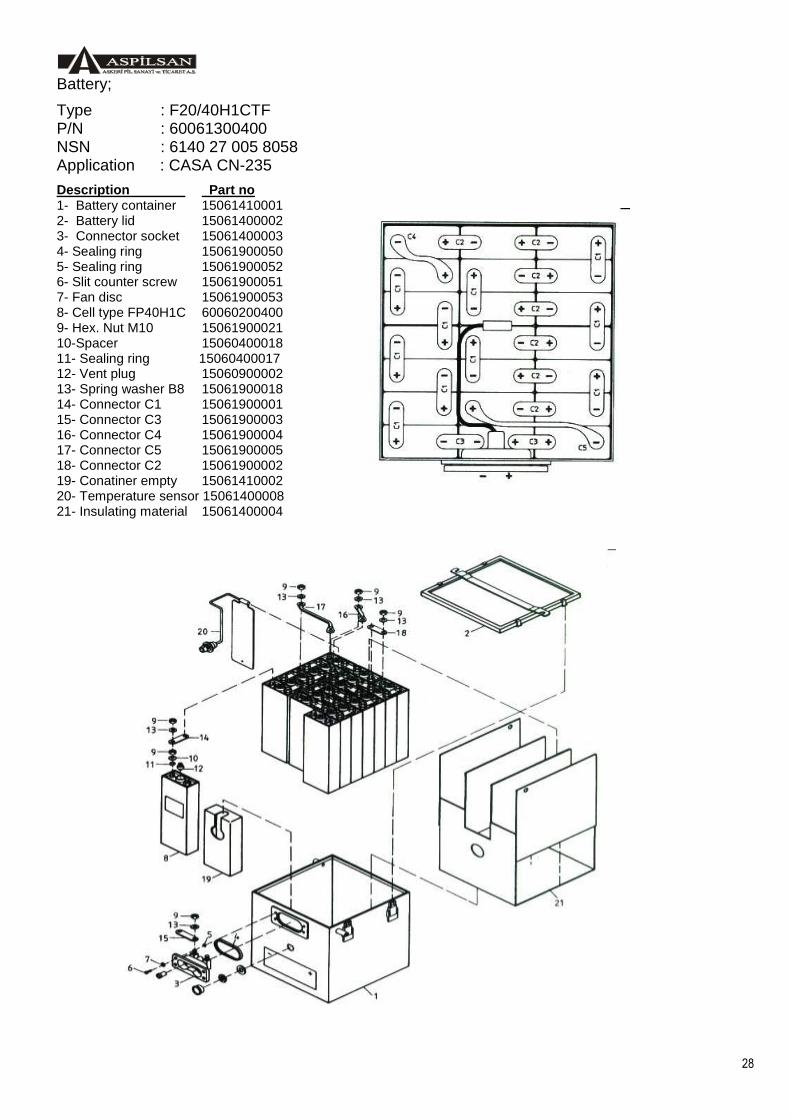
Battery;
Type : F20/40H1CTF P/N : 60061300400 NSN : 6140 27 005 8058 Application : CASA CN-235
Description Part no 1- Battery container 15061410001 2- Battery lid 15061400002 3- Connector socket 15061400003 4- Sealing ring 15061900050 5- Sealing ring 15061900052 6- Slit counter screw 15061900051 7- Fan disc 15061900053 8- Cell type FP40H1C 60060200400 9- Hex. Nut M10 15061900021 10-Spacer 15060400018 11- Sealing ring 15060400017 12- Vent plug 15060900002 13- Spring washer B8 15061900018 14- Connector C1 15061900001 15- Connector C3 15061900003 16- Connector C4 15061900004 17- Connector C5 15061900005 18- Connector C2 15061900002 19- Conatiner empty 15061410002 20- Temperature sensor 15061400008 21- Insulating material 15061400004

29
Battery;
Type : F20/25H1C-L39 P/N : 60161200252 NSN : -- Application : Learjet-L39
Description Part no
1 Battery container
15061260001
2 Battery lid 15061260002
3 Cell type FP25H1C
15386020250
4 Connector D1 15061900006
5 Connector D2 15061900007
6 Vent Plug 15060900011
7 Sealing Ring 15060250016
8 Spacer 15060250017
9 Hex.Nut M8 16061900020
10 Spring Washer B8
15061900017

30
31

32
14. UL-10 Charger / discharger The UL-10 is a microprocessor controlled charger and discharger in a modular design using the latest semiconductor technology. The unit can be used to charge and discharge any type of rechargeable battery with a rated voltage between 1,2V and 24V and a rated capacity of 1Ah to 200Ah. Once the characteristic parameters of the battery (rated voltage, rated capacity, and number of cells) have been entered and after preselection of a suitable program from 10 available programs, the UL-10 operates fully automatic. The unit can also be used for any charging and discharging operation. The operator is guided by the unit while making the entry. The unit and operation are monitored by an integrated test system (self test). In addition, a plausibility check in several programs ensures that no inadmissible parameters are able to entered, thus preventing an overload of the battery. In addition, faults in the battery are able to recognised. During a program run, all input parameters of this program and all measured values are stored after each charging step (main charge, recharge, etc.), and can be printed out at the end of the program. Customised parameters can also be programmed by the user. After execution of an automatic program, the battery is immediately ready for service. The individual cell voltages can be measured during charge or discharge by means of two measuring circuits. For this the P key (printer) must be depressed briefly to switch to the print mode. Technical Data
AC input : 220V ±10% 45 – 65Hz 2200VA Fuse : 16A DC output : 1600W Charge : 0,1 – 36VDC 0,1 – 40A Discharge : 1 – 38VDC 0,1 – 40A Tolerances
Voltage : 1,0% Current : 2,0%
Operating temperature
: -20 to +45ºC
Dimensions Width : 504,0mm
Height 241,5mm Depth 400,0mm
Weight 47kg Figure -9 UL-10 Charger / discharges device