tj auto (3 speed) atlas ii shifter
TRANSCRIPT

KIT CONSISTS OF:No. Qty Part No. Description
P.O. Box 247, 4320 Aerotech Center Way Paso Robles, CA 93447Telephone: (800) 350-2223 Fax: (805) 238-4201 PAGE 1 OF 4 Page Rev. Date: 03-25-19P/N: 303002L
1. 1 KIT 302010 ATLAS BAGGED HARDWARE KIT2. 1 KIT 302011 ATLAS BOOT & KNOB KIT3. 1 302051 TWIN STICK BASE MOUNT4. 1 302068 TWIN STICK HANDLE (TJ) AUTO REAR5. 1 302068-1 TWIN STICK LEVER (TJ) AUTO FRONT6. 1 302077 TWIN STICK TUBE TJ AUTO .8757. 2 303121 1/2"-13 JAM NUT (SHIFTER KNOBS)8. 4 303125 "O"-RING9. 2 723757 3/8"-24 x 2" ALL THREAD GRD 510. 1 725018 STUD BOLT 1/2"-13 x 3.750 LG.
On this shifter, we DO NOT use a Jam nut located on the front of the base mount. We use an "O"-Ring on the all-thread shift link to retain it in place.
As of January 1, 2005, we have changed the design of our shifter tower. We no longer us a set of Zerk fittings on the tower and have omitted the white nylon bushings. The new design uses a Igus black bushing which does not require grease. These bushings are not interchangeable. White bushings: 303080 (large) 4 required Black bushings: 303081 (large) 4 required 303095 (small) 4 required 303096 (small) 4 required
Atlas Shifter Linkage Upgrade: The connection rods for the Atlas were designed to be universal so they could be adjusted for the various drivetrain lengths. The stock linkage works well for the majority of applications and vehicles. The extreme racers and rock crawlers, on the other hand, were looking for a linkage that would withstand the abuse that they are putting their rigs through. The two kits offered are upgrades that work with the standard handles and use heim joints that are bolted to the Atlas linkage. Anyone can upgrade to these kits as they will work on all Atlas ridged mounted twin stick applications, P/N 303040 or P/N 303041. View the applications descriptions online.
TJ AUTO (3 speed) ATLAS II SHIFTER
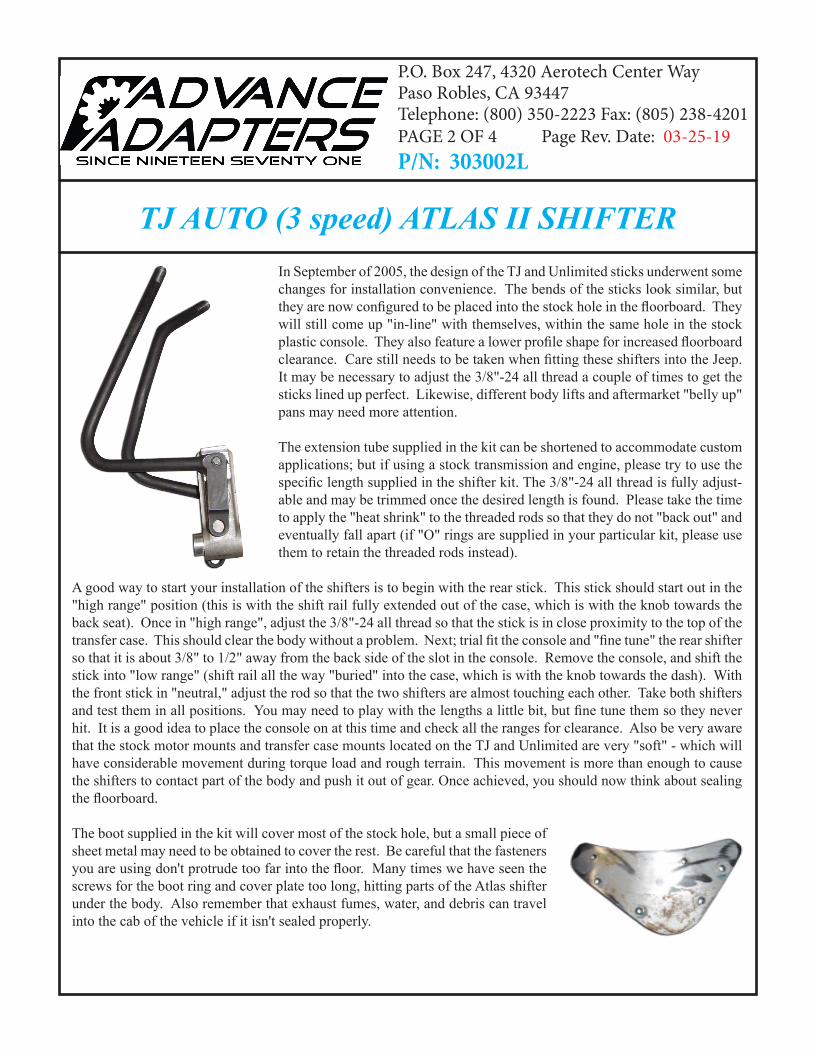
TJ AUTO (3 speed) ATLAS II SHIFTERIn September of 2005, the design of the TJ and Unlimited sticks underwent some changes for installation convenience. The bends of the sticks look similar, but they are now configured to be placed into the stock hole in the floorboard. They will still come up "in-line" with themselves, within the same hole in the stock plastic console. They also feature a lower profile shape for increased floorboard clearance. Care still needs to be taken when fitting these shifters into the Jeep. It may be necessary to adjust the 3/8"-24 all thread a couple of times to get the sticks lined up perfect. Likewise, different body lifts and aftermarket "belly up" pans may need more attention.
The extension tube supplied in the kit can be shortened to accommodate custom applications; but if using a stock transmission and engine, please try to use the specific length supplied in the shifter kit. The 3/8"-24 all thread is fully adjust-able and may be trimmed once the desired length is found. Please take the time to apply the "heat shrink" to the threaded rods so that they do not "back out" and eventually fall apart (if "O" rings are supplied in your particular kit, please use them to retain the threaded rods instead).
A good way to start your installation of the shifters is to begin with the rear stick. This stick should start out in the "high range" position (this is with the shift rail fully extended out of the case, which is with the knob towards the back seat). Once in "high range", adjust the 3/8"-24 all thread so that the stick is in close proximity to the top of the transfer case. This should clear the body without a problem. Next; trial fit the console and "fine tune" the rear shifter so that it is about 3/8" to 1/2" away from the back side of the slot in the console. Remove the console, and shift the stick into "low range" (shift rail all the way "buried" into the case, which is with the knob towards the dash). With the front stick in "neutral," adjust the rod so that the two shifters are almost touching each other. Take both shifters and test them in all positions. You may need to play with the lengths a little bit, but fine tune them so they never hit. It is a good idea to place the console on at this time and check all the ranges for clearance. Also be very aware that the stock motor mounts and transfer case mounts located on the TJ and Unlimited are very "soft" - which will have considerable movement during torque load and rough terrain. This movement is more than enough to cause the shifters to contact part of the body and push it out of gear. Once achieved, you should now think about sealing the floorboard.
The boot supplied in the kit will cover most of the stock hole, but a small piece of sheet metal may need to be obtained to cover the rest. Be careful that the fasteners you are using don't protrude too far into the floor. Many times we have seen the screws for the boot ring and cover plate too long, hitting parts of the Atlas shifter under the body. Also remember that exhaust fumes, water, and debris can travel into the cab of the vehicle if it isn't sealed properly.
P.O. Box 247, 4320 Aerotech Center Way Paso Robles, CA 93447Telephone: (800) 350-2223 Fax: (805) 238-4201 PAGE 2 OF 4 Page Rev. Date: 03-25-19P/N: 303002L
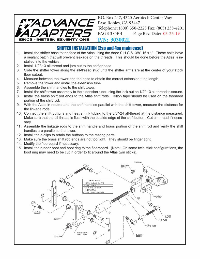
SHIFTER INSTALLATION (2sp and 4sp main case) 1. Install the shifter base to the face of the Atlas using the three S.H.C.S. 3/8"-16 x 1". These bolts have
a sealant patch that will prevent leakage on the threads. This should be done before the Atlas is in-stalled into the vehicle.
2. Install 1/2"-13 all-thread and jam nut to the shifter base.3. Slide the shifter tower along the all-thread stud until the shifter arms are at the center of your stock
floor cutout.4. Measure between the tower and the base to obtain the correct extension tube length.5. Remove the tower and install the extension tube.6. Assemble the shift handles to the shift tower. 7. Install the shift tower assembly to the extension tube using the lock nut on 1/2"-13 all-thread to secure.8. Install the brass shift rod ends to the Atlas shift rods. Teflon tape should be used on the threaded
portion of the shift rod. 9. With the Atlas in neutral and the shift handles parallel with the shift tower, measure the distance for
the linkage rods.10. Connect the shift buttons and heat shrink tubing to the 3/8"-24 all-thread at the distance measured.
Make sure that the all-thread is flush with the outside edge of the shift button. Cut all-thread if neces-sary.
11. Assemble the linkage rods to the shift handle and brass portion of the shift rod and verify the shift handles are parallel to the tower.
12. Install the e-clips to retain the buttons to the mating parts.13. Make sure the brass shift rod ends are not too tight. They should be finger tight.14. Modify the floorboard if necessary.15. Install the rubber boot and boot ring to the floorboard. (Note: On some twin stick configurations, the
boot ring may need to be cut in order to fit around the Atlas twin sticks).
P.O. Box 247, 4320 Aerotech Center Way Paso Robles, CA 93447Telephone: (800) 350-2223 Fax: (805) 238-4201 PAGE 3 OF 4 Page Rev. Date: 03-25-19P/N: 303002L

Atlas shifter problem check list: When installing the twin stick shifters, there are a few key areas that must be addressed. One of the most common difficulties we hear is that "my unit isn't shifting fully into one of the gear ratios". Incorrect adjustment of the shift handles to the linkage rods is normally the cause. With both shift rods in neutral, the linkage rod (connected to the shift handles) must be parallel with the aluminum shift tower. Refer to the photo left.
Another concern that we've heard is that "my Atlas seems to be hard to shift". This problem could be one of two areas. The brass shift rod ends that the shifter linkage rods connect to are too tight, causing a binding effect on the shifter linkage. The brass shift rod ends should be installed until tight, then loosened enough to align to the shifter button.
If a unit has a tendency to pop out of gear, an area to check is proper floorboard clearance in relation with the shift handles. This problem
mainly occurs on Jeep TJs, since floorboard modifications are required. Most reported problems have been overcome by simply providing additional clearance. The problem of popping out of gear can also be caused by incorrect alignment of the shifter handles as previously discussed and/or a unit in which the detent set screws have been loosened.
The last of the most common dilemmas we hear is that "the shifter linkage came apart while in operation". The area in question is the all-thread linkage rods. These rods fit into the two shift buttons. To prevent the all-thread from unscrewing out of the shift buttons, a portion of the heat shrink tubing should have been installed (o-rings on a TJ automatic). The heat shrink tubing or o-rings act as a jam nut to prevent the all-thread from unscrewing. DO NOT use a jam nut on these linkage rods because it will cause binding of the shifter linkage.
P.O. Box 247, 4320 Aerotech Center Way Paso Robles, CA 93447Telephone: (800) 350-2223 Fax: (805) 238-4201 PAGE 4 OF 4 Page Rev. Date: 03-25-19P/N: 303002L