title theory and observation of dielectric relaxations...
TRANSCRIPT

Title Theory and Observation of Dielectric Relaxations due to theInterfacial Polarization for Terlamellar Structure
Author(s) Zhao, Kongshuang; Asaka, Kinzi; Asami, Koji; Hanai, Tetsuya
Citation Bulletin of the Institute for Chemical Research, KyotoUniversity (1989), 67(4): 225-255
Issue Date 1989-12-15
URL http://hdl.handle.net/2433/77311
Right
Type Departmental Bulletin Paper
Textversion publisher
Kyoto University
Bull. Inst. Chem. Res., Kyoto Univ., Vol. 67, No. 4, 1989
Theory and Observation of Dielectric Relaxations due to the
Interfacial Polarization for Terlamellar Structure
Kongshuang ZHAo*, Kinzi ASAKA**, Koji ASAMI** and Tetsuya HANAI**
Received September 19, 1989
On the basis of electrostatic laws, a dielectric theory is developed to explain dielectric relaxations due to the interfacial polarization for terlamellar structure composed of three phases. It is proven that the derived
formula is equivalent to that for a series combination of three lumped capacitance-conductance circuit models. Some dielectric observation was carried out on composite systems of distilled water, a Teflon film
and potassium chloride solutions, the results being in quantitative conformity with the dielectric theory developed.
KEY WORDS: Terlamellar structure/ Dielectric Relaxation/ Electrical conductivity/ Interfacial polarization/ Maxwell-Wagner relaxation/ permittivity/ Teflon film/
I. INTRODUCTION
In order to understand the characteristics of membranes of practical use such as filtration films, dialysis films, ultrafiltration membranes and reverse osmotic mem-
branes, it is important to obtain information on those membranes in electrochemical equilibrium with the ambient aqueous solutions. Dielectric properties relevant to the
ion permeation through the membranes are usually measured for the membranes sand- wiched between two aqueous phases as shown in Fig. 5 later on.
This kind of membrane-aqueous phase system is assumed to be a series combina- tion of three phases, each of which is represented routinely by a lumped capacitance-con-
ductance (C-G) model as shown in Fig. 4. This model, however, should be subjected to
justification in terms of electrostatic field quantities and laws applied to the composite dielectrics prior to the routine use of a lumped C-G model1-8).
In the present work, a heterogeneous dielectric in terlamellar structure is for- mulated theoretically by means of electrostatic quantities and laws to show the dielectric
relaxation behaviour. According to a consequent formula, the terlamellar structure will be seen to be equivalent to a series combination of the three lumped C-G models. Some experimental results of dielectric relaxation observed in the terlamellar dielectrics
are shown to confirm the theoretical formulation.
* l R.W : Department of Chemistry, Northeast Normal University, Changchun, China. ** /E41-ft : Laboratory of Dielectrics, Institute for Chemical Research, Kyoto
University, Uji, Kyoto 611, Japan.
( 225 )

K. ZHAO, K. ASAKA, K. ASAMI and T. HANAI
II. CONSTRUCTION OF THEORY ON THE BASIS OF ELECTROSTATIC
FIELD LAWS
2.1 Fundamental Relations in the Quasi-electrostatic Field
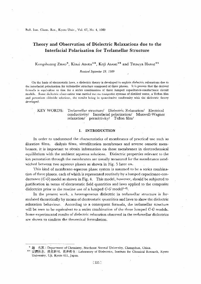
A triphase system in terlamellar structure is depicted in Fig. 1, which is composed of Phase b (henceforth referred to with a subscript b), Phase f (subscript f) and Phase a
(subscript a) inserted in a parallel-plate capacitor with unit area. Each electrode plate is charged with the electric charge Qb or Qa, respectively. The charge is assumed to ac-
cumulate on the boundary between Phases b and f, the charge density being denoted by 0'b. Similarly the charge is assumed to accumulate on the boundary between Phasesf
and a, the charge density being ca. Figure 1 includes electrostatic laws and expressions necessary for the explanation below, where vector quantities are assumed to have
positive values for pointing to the right. For a system with a uniformly charged infinite plane, electrostatics gives a succint
relation that the contribution of the surface charge density to electric flux density, or elec- tric displacement, outside the plane is equal to the surface charge density divided by
two. Hence, the electrode charges Qb, Qa and the boundary charge densities (lb, o'a give rise to the constituent parts of the electric flux density, or the electric displacement, as
shown in the lowest part of Fig. 1. The elctric flux densities Db, Df and Da are thus represented as follows:
Db = Qb—Qc, _ ab — (la(1) 2 2 2•
Df=Qb2 +2b-2(2)
Da = Qb 2 Qa2b2(3)
The relation between the flux density Db, Df or Da and the electric field Eb, Ef or Ea is
given by
Eb =-----DbEf =DfDaand Ea=D,,(4) EvCb EvEfEvEa
respectively, where E is the relative permittivity of the respective phase, and
Ea=0.088542 pF cm-1 is the permittivity of vacuum. Potential differences Vb, V1 and Va for respective phases are given by
Vb = Ebdb, Vf = Efdf, and Va=Eada ,(5)
where db, df or da denotes the thickness of the respective phases. The total potential difference V is the sum of Vb, Vf and Va, that is,
V = Vb + Vf + Va.(6)
Using the electrical conductivities Kb, If and Ka, the electric current densities ib, if
(226)

Dielectric Relaxation for Terlamellar Structure
charge density on the boundary
electrode 6b6a ___electrode b Phase b'Phce-f iPhaseaa electric---3`—}
O-------field Eb 1 EfEa----------O ft
electrode electric flux s'-- charge
-density Db-<_Df_-Da-a --Q
distance I------ b--- ,r d----4-1----- df----.1----.1~da whole, d>
permittivity EbEfea conductivity KbKfKa
DbOf,
potentialEb=FyEbEf =CV E f,a —Ev Ea difference<Vb----------I. -- Vf I-( Va-------I Vb = Ebdb, Vf = Ef df 1 Va----- Eada,
-<-- whole, V = Vb -I- V f -I-- Va , -------------I current lb = Kb Eb ) If = Kf Ef 5 la= Ka Ea ,
increasing rated Ib-If ,dta = if - la , dtdt QbI bIa -->"Qa/---)
I -----------by external V-source)-----------I
I=dQb-I-ib , I=—dQa "rla, dtdt
flux density D
D due to Qb Qb/2 ~Qb /2 Qb /2 I D due to Qa -Qa /2 I-Qa /2 I -Qa /2 D due to Qb -0b /2 I ab /2 I ab /2
D due to as -0a /2~-0a/2~ 6a /2 I - Qb Qa 6b_Oa_Qb QaGbGa total D
, Db--2 - 22 ,Da2 - 2+2+ 2 ,
D_Qb_Qa+Qb-6a f2 2 2 2
Fig. 1. Quasi-electrostatic fields, the related electric phenomena and the laws concerned for a terlamellar structure in a parallel-plate capacitor.
(227)

K. ZHAO, K. ASAKA, K. ASAMI and T. HANAI
and is are given by
ib = KbEb, if = KfEf, and is = KaEa.(7)
As regards the charge density a6 per unit area on the boundary surface between Phase b and Phase f, its increasing rate d Qbldt against time t is the difference of the current densi-
ty ib and if, that is,
dab dt_ab(8)
In a"similar manner, we have
daa _ . dt—zf—ia.(9)
The inflow current density I must be equal to the outflow current density owing to the total charge conservation law, being given by
d ib=I=— dt+ia.(10) dt
From Eqs. 10, 8 and 9, we have
dt(QbQa) =Zb+2a=dt (b6a )•(11)
Integrating Eq. 11 with null integration constant corresponding to the neutral condi- tion, we have
Qb + Qa = — (ab + aa).(12)
The above are all of the expressions to describe the terlamellar system shown in Fig. 1.
For simplification of succeeding calculation, we put as follows:
S13 5bEE'OfEE'OaEE--------'(13) UbUfU6
—(14) =------kf =EUEbEUEfka=EUEa---------'() 2.2 Guideline and Procedure of Successive Calculation
The course of successive calculation is apt to be in confusion because of too mamy formulas and too tedious rearrangement. The following items are pointed out to per-
form the calculation efficiently.
(i) In the present problem, independent variables are Qb, Qa, Qb and Ca in princi- ple. Since Eqs. 1, 2 and 3 include a term Qb—Qa, the calculation can be simplified in
practice to obtain three independent variables Qb— Qa, 6b and Ca. Hence we have to find three formulas which include the three variables only.
(ii) By eliminating Qb — Qa among the three formulas obtained, two formulas are
(228)

Dielectric Relaxation for Terlamellar Structure
derived which include ab and Ca only. The two formulas are to be simultaneous differential equations of the first order with respect to time t.
(iii) By eliminating ab among the two simultaneous differential equations of the first order, we derive a differential equation of the second order including Ca only. By solving the second order differential equation, a solution of Ca can be obtained.
(iv) A solution of ab can be derived by use of the solution of Ca. Solutions of Qb and Qa are also obtained by use of Qb and Ca.
(v) Next, solutions of if, ib and is are derived by use of Qb, Qa, ab and Ca obtained above.
(vi) The inflow and outflow current density I is expressed with dQb/dt, ib, dQa/dt and ia. By use of the formulas of current density I, the apparent complex permittivity for the whole system can be expressed in terms of Qb, ib, Qa and ia.
(vii) The expressions of Qb, Qa, ib and is obtained are introduced into the complex permittivity formula of the whole system derived above. After rearrangement an ex-pression of the complex permittivity is written out to represent two dielectric relaxa-tions.
(viii) In the course of rewriting and rearranging these expressions, some terms are expressed with a factor of 1/[1+j (co/cop)] and 1/[1+j (w/w(2)], which signify the dielectric relaxations. Further calculation with keeping this type of factors is very in-tricate and difficult to attain to the final expressions. An ingenious method of rearrange-ment is to make up a factor 1/[( w+wp) (/w+WWQ)], which is a synthesized form of the two factors: 1/[1+j(w/op)] and 1/[1+j(w/wQ)]. This particular technique of calculation makes further rearrangement much easier.
2.3 Replacement of various Expressions
For the sake of simplification in the course of cumbersome calculation; some replacements and the consequent simplified relations are summarized here.
S = 8b + 8 + 8a,(15)
REdb+df+da(16) Kb 1ff ~a
Tb ob — (3f — oa, Ta ob + of — 6,(17)
Jmka+kf, G=kb+kf,(18)
Hmkb — kf, Kmka — kf,(19)
L = kb (Oa + of) + kfab, M = ka (ob + of)+kf5a,(20)
H — K=kb — ka= Kb— Ka ,(21) EUEb EUEa
A--S,B=—SOa,G=SV,(22)
D --55b,E—s,F—SV,(23) (229)

K. ZHAO, K. ASAKA, K. ASAMI and T. HANAI
A + E =s-l (L + M)
=----s-l [kb(oa+Uf)+ka(ob+Uf)+kf(ub+oa)1,(24)
A — E=----s-l(L — M)
-1-----[kb(Ua+Ufkabf)kf(ubua)1,(25)
AE=-----,
=[kb(U a+of)+kfOb][ka(0b~'Of)+Alva I,(26)
BD =-----ObOa= ----Obba (kb — kf) (ka — kf),(27)
AE — BD =S (kbka5f + kbkfOa + kakfOb ),(28) AK+DH= —Kkb= —kb(ka—kf),(29)
BK + EH = —Hka = —ka (kb — kf),(30)
(AK + DH) —(BK+ EH) =kf(H—K)=kf(kb—ka),(31)
AF= SV=S'2[kb(5a+Of)+kfOb](ka—kf),(32)
DC =—K----VOb=-----S2V(kb—kf) (ka—kf)Ob,(33)
AF — DC = S (ka — kf) kb.(34)
2.4 Derivation of three Expressions including three variables Q,, — Qa, al, and o'a
Substitution of Eqs. 5, 4, 1, 2, 3, 13, 15 and 17 in turn into Eq. 6 yields a new expression of V as follows:
V = Vb + Vf + Va = Ebdb + Efdf + Eada,
Db dDf b d+Da da, E
a£bEa£ff Eva
= 2 (bab 2a------Ca.(35) Rearrangement of Eq. 35 with respect to Qb—Qa gives
Qb —Qa=S(Tbvb+ TA' a+2V).(36) (230)

Dielectric Relaxation for Terlamellar Structure
In a similar manner, substitution of Eqs. 7, 4, 1, 2, 3, 18 and 19 in turn into Eq. 8 yields
a new expression of do-b/dt as follows:
ddb = (Qb a)-26b— 6a,(37)
Substituting Eq. 36 for Qb— Qa in Eq. 37 yields the following equation:
d6b—_L~ b—H~aa+HV(38) dt S SS
Replacement in the above equation by Eq. 22 gives
dub = A6b + Boa + C.(39) dt
In a similar manner, Eq. 9 is rearranged as
d6 a —_K0b6b—M---a s—KV(40) dtS SS
Hence, replacement in the above equation by Eq. 23 gives
d6a dt= Dab +Eaa+F.(41)
Here Items i and ii in subsection 2.2 have been dealed with.
2.5 Derivation and the Solution of the Second Order Differential Equation of a.
Eliminating a.b-term between Eqs. 39 and 41, we have
dab= (AE —BD)6a+AF—DC—Adda.(42)
Differentiating Eq. 41 with respect to t, we have
d26, — D dab — Ed6a —dF(43) dt2 dtdt dt •
Substituting Eq. 42 for Ddcb/dt in Eq. 43, we have the second order differential equation
of 6a as follows:
~Ca—(A+E)ddas+ (AE —BD)6a=DC—AF+dF.(44) For the purpose of obtaining a general solution of Eq. 44, we consider the following
linear homogeneous differential equation:
d2a —(A+E)----d6a+ (AE — BD)a a= 0,(45) dt2dt
which is the form with left side zero in Eq. 44. A general solution of this Eq. 45 is assumed to have the following form:
( 231

K. ZHAO, K. ASAKA, K. ASAMI and T. HANA!
Ca= const X eat,(46)
where m is a certain constant to be determined below. Substituting Eq. 46 for Ca in Eq. 45, we have
m2—(A+E)m+(AE—BD)=0.(47)
Two roots mQ and mp of this quadratic equation 47 are readily obtained. For the sake of convenience during the calculation, two quantities WQ and Wp are introduced which are
just opposite to mQ and mp in sign. Hence the expressions of WQ, cop, mQ and mp are given as follows:
042,==- —mQ,(48)
= 2[—(A+E)+^(A+E)2-4 (AE —BD)](49)
2[—(A+E)+^(A—E)2+4BD],(50) c~p = —mp(51)
2[—(A+E)—^(A+E)2-4 (AE —BD)](52) = 2[—(A+E)—^(A—E)2+4BD].(53)
Mutual situations among mQ, mp, COQ and wp are shown schematically in Fig. 2. Using the relation between the roots and the coefficients of Eq. 47, we have
COQ+ (Op = — (mQ+mp)
(A+E) = —1(L +M)(54)
= —1(55)
(UQcup = mAmp = AE — BD(56)
—1 + kbkfoa + kakfob) >0.(57)
Therefore, we have always c,WQ> 0 and W p> O. Hence the general solution of Eq. 45 is expressed as
Ca = const X e_a,Qt + const X e—`apt.(58)
The boundary charge density Ca of this Eq. 58 tends toward zero for t—>. 00, being
negligibly small after sufficiently long time t. Now a particular solution of Eq. 44 will be derived provided that an external a.c.
voltage applied to the electrodes is expressed as
(232)

Dielectric Relaxation for Terlamellar Structure
— wQ =—mQ
(pQ+wP _(MQ+mP) 2 2
( A+E) 2
positive —wP= — mP
__0
negative — mp
1/(A—E)2+4BDI mQ+mP A+E
2 2 1 ----------------
V(A—E)2+4BD -- mQ
Fig. 2. Relative location among mQ, mp, mQ and mp in relation to the roots of Eq. 47.
V = Vo ,(59)
where Vo is the amplitude of the a.c. voltage, CO = 27r x frequency is the angular fre- quency, and j= ^-1 is the imaginary unit. The quantities C and F given by Eqs. 22 and 23 also include the factor el'''. Hence 6a given by Eq. 44 must have the following
form:
Ca = a oeiwt,(60)
where (fao is the amplitude of (fa. Substituting Eq. 58 for as in Eq. 44, we have
[(jca)2—(A+E)jw+(AE-BD)]aa=DC—AF+jwF.(61)
Hence we have
__ DC — AF+ jwF(62))2A + Ecu+AE — BD()
Taking advantage of the previous analysis for the two roots mQ and mP in Eq. 47, we can rewrite the denominator of Eq. 62 as follows:
DC — AF+jcwF va_(J~ — mQ) (/(1)—mP)(63)
DC — AF+jcaF (jw + WQ) (jcu+LOP)(64)
Here Item iii in subsection 2.2 has been dealt with.
2.6 Derivation of Expressions for oa, o,Qb,Qa,ib,if and is By use of Eqs. 22 and 23, Eq. 64 is rearranged as
(233 )

K. ZHAO, K. ASAKA, K. ASAMI and T. HANAI
_,juwK—(AK+DH) V va(65) (jai+UQ)(Jw+ (op) S'
Substituting Eq. 65 for Qa in Eq. 41 and using d/dt = jw, we have
66 jwH—(BK+EH) V() us=(jw+WQ)(jai+cap) S•
By use of Eqs. 29, 30 and 19, Eqs. 66 and 65 are rearranged as
kb — kf --------------------------jai+ ka 66 =V(67) S (j
w+coQ)(Jw+(op)
=ka—kfjai +kb caV(68) — S (Jw + NO (jai + (op)
For further rearrangement of formulas, we take notice of the following identities:
(R+ 1jwr+a _ a 11w)(jw+ wQ) (jw +(0P)jwuQwp +jw(PYWQwp—a)+wowp(Y+Pa)—(wo+(op)a.(69)
WQwp(jai + m0)0w + (op)
juJP + a (jai +(uQ)(JW+(Op)
a a
1 (Op—+---------1Rcoo(70) wQ— wp 1 +j-----
(Op wQWP 1 +jQ
icy----------— w (Op—_w (1-1(71) 1 +j--wo1+j----o1+jw)
WOWOWO
By use of Eq. 70, Eqs. 67 and 68 are rearranged to the expressions consisting of two relaxation terms as follows:
ka — 11ka _kb—kf capp kb—kf() 66[S(wQ— (op) 1 +j----(U)+S(UQ—(up) 1 + j (0Q,(11V.72
—ka — kf (op1_ka — kf 1coopV.73
kbkb
o.a[S( a)Q— cap) 1 +'w S(UQ— cop) 1+w ]() j(u pljWQ
The sum of Eqs. 67 and 68 is given by
ub + Ca =kb — kajai+ kf V.(74) S • (jw+U(2) (jai +(up)
(234 )

Dielectric Relaxation for Terlamellar Structure
By use of Eq. 70, Eq. 74 is rearranged to
— 11 —~
/kb-----------— ka cop +kb — ka (00V. 6b + C.-=[S(WQ—wcop) 1+j----w(75) S(WQ—coP) 1+j----
Q
The expressions of Qb and Qa are derived by addition or substraction of Eqs. 12 and 36 by aid of Eq. 17 as follows:
Qb = s [ — (aa + af) 6b — 5aaa + V].(76)
Qa= 1 [—abab—(ab+af)oa—V].(77)
Substitution of Eqs. 4, 1, 2, 3 and 36 into Eq. 7 leads to the following expressions for if, ib and ia:
if S kf (abQb — aaca + V) ,(78)
1 tb = kb [ — (60 + 3f) 6b — aaCa + V[ = kbQb ,(79)
Za — S ka [ abab + (ab + Of) Qa + V] _ — kaQa.(80)
Here, we have completed Items iv and v in subsection 2.2.
2.7 Derivation and Calculation of the Complex Permittivity Formula for the Apparent Capacitor System .
In order to derive the complex permittivity formula for the capacitor, attention is
paid to a connection between the capacitor and the exterior circuit shown in Fig. 3. If we use the current density Iwhich is defined and used in Fig. 1, the total current in Fig. 3 is given by I • ', where F is the electrode surface area. The total current /.F is represented by the voltage V multiplied by the complex conductance G*, that is,
I•F = VG*.(81)
The complex conductance G* is given by
G*=jwC*= jWE*Ea d ,(82)
where C* is the complex capacitance, m=27rf the angular frequency of the a.c. voltage applied, E*=E+K/(jwEU) the complex relative permittivity of the composite capacitor, and d is the separation or distance of the two electrodes.
By use of Eqs. 82, 81, 10, and d/dt jw, the expression of E*/d is rearranged as follows:
(235)

K. ZHAO, K. ASAKA, K. ASAMI and T. HANAI
E* G* I(83) d jweUI'jweUV
_ —.7WQ + 2 =+ 2a(84) jwe,VEUV jwEUV
7wQb + Zb = Qb+ is(85) jwEUVEUVjWEUV •
Substituting Eq. 76 for Qb and Eq. 79 for ib in Eq. 85 yields the following formula.
E* __+ kb d EUSjwEUS
kb+ SV1k+—ofab — 8a (Qb+(fa)]. (86)
E
abj~) Substituting Eq. 67 for Qb and Eq. 74 for 66+ua in Eq. 86, we have the following formula
after tiresome rearrangement:
E* 1 kbkb +------++( (87)Jo)d EUS ~EUS EUS2(1 + 1kb jw).7wr1 (jw+WQ) (jw+Wp)'
where
r7= —(kb— Ica) Oa- (kb —kr)Of,(88)
= — ka (kb — kf) Of — kf(kb — ka) 3a.(89)
Now the rearrangement of Eq. 87 will proceed to the function form with relaxation terms.
By use of Eq. 69, the third term of the right side of Eq. 87 is rearranged as follows:
voltage generated electrode
chargeVsurface area'rea/cm:::'rcm
2 permittivity, E <!'
`'€ <:conductivity, K <' Qa
------- distance d
/current trit
voltage source with angular frequency w
Fig. 3. Explanation of a complex permittivity for the whole of the triphase system in terms of the outside arrangements.
( 236 )
Dielectric Relaxation for Terlamellar Structure
e* 1 + kb
d EUS JWEUS
jw(wkPri—~)Iwep(ri+ ----)_(WQ+WF)( +EVS2[JwQcop+(Qwp (jw + W(2) (JW + cop)------------------------------------------------------------------------------1(90)
1 kb + kbC E„S Jw E„S jWSSwQp
icyriQL"i—()+wQwp(ri+----b )—(wQ+wp)~ kb +
EUS2WQmp(jw+WQ)(jW+Wp)(91)
The sum of the second and the third terms of Eq. 91 is
11 1 the sum = JW E,, db + df + da jw EaR '(92) Kb Iff 1a
where
R°—db+-+da.(93) Ka
Thus Eq. 91 is simplified to
E* 1 + 1 d euSJwEUR
+ 7w (wowP'7 — kbC) + wowp (kb>1 + b) — (wQ + (OP) kbC94 EUS2WQWP(Jw + wQ) (Jw+cup)'()
Each term in the numerator of the third term of the right side of Eq. 94 is rearranged respectively to
Y Jw(wQ.00—kbb)
= jwS R kb — ka )2kfabca + (kb— kf )2kaobo f + (ka — kf )2kboaa f ], (95)
jw(1).
yY WQWP(kb)?+S)—(WQ+(P)kbb
= Sr(kb—ka )2k12 obaa+(kb— kf)2ka2 8601+(ka— kf )2kb2 Oaa.f • (96)
A.
Thus Items vi and vii in subsection 2.2 are all completed. In a similar manner, Eq. 84 yields the same expression as Eq. 94, if Eq. 77 for Qa
and Eq. 80 for is are substituted in Eq. 84.
(237)

K. ZHAO, K. ASAKA, K. ASAMI and T. HANAI
2.8 Concluding Summary of the Theoretical Development based on Electrostatic Field Laws
The expressions derived and the associated conclusion are summarized as follows: From Eq. 94, the complex relative permittivity E* for the whole system in
terlamellar structure is given by
*= d + djwD+A +------d97 EaS EVS2WQwp (jw+WQ)(jw+wp) iwE„R•()
Alternatively, by use of Eq. 70, Eq. 97 is rearranged as
AA
E*=d d----------------------- f(Op ~+~Q l E,S EVS'zwQwp (wq—wp)L1+. w1+' w J cop j wQ
d (98) + . EUR'
In the right side of this Eq. 98, the first term means the limiting permittivity at high fre- quencies, d/R in the third term giving the limiting conductivity at low frequencies. The second term is composed of two single relaxation terms: 1/(1 +jw/wp) and 1/(1 +jw/WQ).
Hence it is concluded that Eq. 98 for the terlamellar system shows two dielectric relaxations due to the interfacial polarization. The quantities appearing in Eq. 98 are
summarized as follows:
J=Ub+Uf'+ Oa —-----db+------df,+ -------da E„EbEUEf EvEa
r (Cb+C+Ca),(99)• l-r
R b ~+ Oa = db da =r 1 +--1 +----1(100) kbkfka Kb ICJ /La(Gb Gf Ga) = S [( kb — ka )2 OAAa + (kb — kf)2kaobof + (ka — kf)2kboad. ], (101) =wQwpr2—k5,(102)
A —1 — ka )2k/oboa + (kb — kf)2ka2abot + (ka — kf)2kb2oa5f ], (103)
A = (.0Q(Up (kb)2 + S) — (wQ + WP) kbC,(104)
=—[(kb— ka) Oa+ (kb —kf)Of],(105)
= —[(kb— ka) kfoa+(kb—kf)kaof],(106)
(238)

Dielectric Relaxation for Terlamellar Structure
WQ+wp= S, [kb(aa+5f)+kf(ab+aa)+ka(ab+af)] (107)
=—(A+E) ,
WQWP =1( kbkaaf + kbkjOa + kakfab) (108)
= AE — BD,
WQ=2[—(A+E)+ ^(A—E)2+4BD],(109)
Wp= 2[—(A+E)— 11(A — E)2 + 4BD],(110) The expressions for A+E, A—E and BD are already given in Eqs. 24, 25 and 27.
III. PHENOMENOLOGICAL REPRESENTATION AND DEVELOPMENT BY MEANS OF THE LUMPED CIRCUIT MODEL
In this section, the theoretical expressions derived on the basis on electrostatic field laws are connected mathematically with the phenomenological representation based on the C-G circuit models.
3.1 Constitution of Dielectric Relaxations by Means of the Lumped G-C Models2' 9)
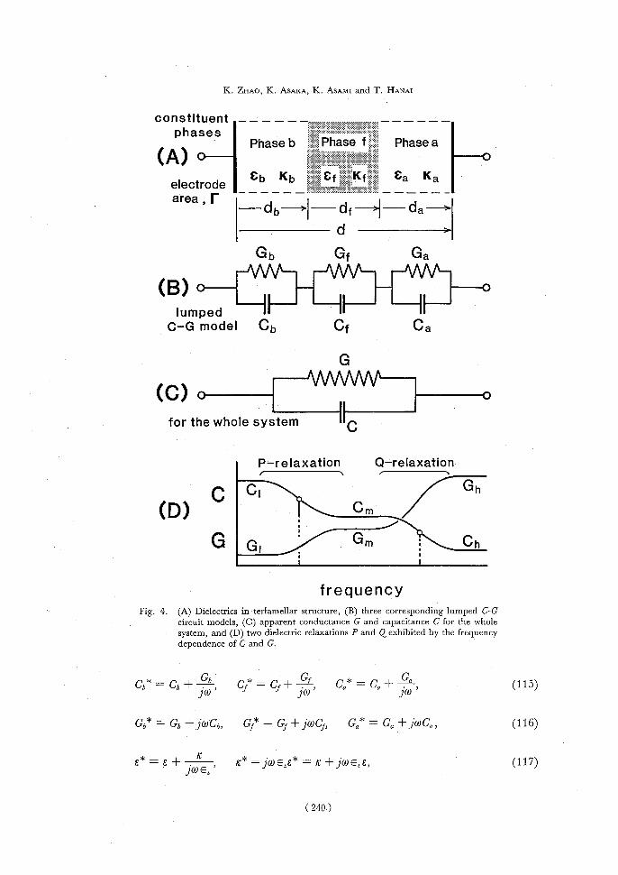
So far, a heterogeneous dielectrics in terlamellar structure has merely been assum-ed to be a series combination of three phases, each of which is represented routinely by a lumped capacitance-conductance (C-G) model as shown in Fig. 4B.
In this instance, constituent phases b, f and a are related to the respective lumped C-G models by the following relations:
C=E,Ed=dG=vd=kC,k=~=,(111)
Cb= EUEbi'=r,CEer=F dbabfafdfaf,
Ca= Eaear=r,(112) da as
FF Gb =rbd
b=k9C9,Gf_— ~f d = kfCf,
Gaad=kaCa,(113)
C*=C+ 1.(1) =C—jC"", G*=jwC*=G+jwC=G+jG", (114)
(239)
K. ZHAO, K. ASAKA, K. ASAMI and T. HANAI
constituent ------__-___
phases Phase b PhasefPhase a
(A)o----------0 electrodeCb Kb Cf Kf Ca Ka area , r--~~I' fI- -tla bd~I ------------
d ------------->
GbGf Ga
lumped II --1I IF C-G model Cb Cf Ca
G
(C) o--------- ------------0 for the whole system I~C
P-relaxation Q-relaxation
C ClGh
•
(D)Cm.
• G Gl.Gm Ch
frequency
Fig. 4. (A) Dielectrics in terlamellar structure, (B) three corresponding lumped C-G circuit models, (C) apparent conductance G and capacitance C for the whole
system, and (D) two dielectric relaxations P and Q exhibited by the frequency dependence of C and G.
Cb* =Cb+----bCf* =Cf+~~,Ca*=Ca+----a,(115) Gb* = Gb + jWCb, Gf* Gf + jWCf, Ga* = Ga + jWCa,(116)
E* _ E+ jUlEa' ~* -= fa) _ + jwevE,(117)
(240.)

Dielectric Relaxation for Terlamellar Structure
£b* — Eb +-------14£f* = Ef+9,Ea* = Ea +------~E,(118) UU
C* = E,E* d= Ev(E+~EV),(119) J G* = K*1.' = (~+ jwEaE)d,(120)
Cb* = eve*, CI'*= EUEf*~,Ca*= Ea£a* ever,* 7,(121)
Gb* =Yab*b,Gf*= lEf*.,Ga*= Xa*d,(122)
f
For a series combination of three sets of lumped capacitances and conductances as shown in Fig. 4B, the complex capacitance C* = C+ G/jco shown by Fig. 4C for the
whole system has already been presented as follows7' 8):
G*=Gi*+C**+~*,(123) hfa
C* = Ch* CI* Ca*(124) Ch*Cf*+ Cf* Ca* + Ca*Cb* '
(Gb +JwC8) ( Cf + 7(OCf) ( Ga +jWCa) (125)
Djw(1 +j-----W(1 +j-----(Op) Cl — Cm++---
1Cm — Ch1 —Ch+G(126) 1 +j-----co1 +j----Jw PcoQ ,
__ c±(CI — Cm)cop+ (Ca, — Ch)wQ+1G(127) hjco + COjw + COj(I)~'
G* jwC*
coco ( C1 — Cm) WPJ (C.Ch) WQJ
= G1 +cop +coo +jWCh, (128) 1+jco1 +jw
copwQ
Ch =chAfca(129)
Cl _ Ch (G1Ga )2 + Cf ( GaGb )2 + Ca ( GbGf)2 (130) D2
CI - Cm= D(wQwpwp)-------------(_E+---wpF+wpCbCCCa—wp2GbGPGa),(131) Cm — ChD (wQwpcop) (E (132)
(241)

K.Zxwo, K. Aswxw, K. AswMi and T. Hwxwi
Ct‐C,,=AD2[CbGb2(CfGa‐CaGf)2+CIGf2(CaGe‐CbGQ)2
+0。0。2(C6Gf‐CfGa)2], (133)
Gl=GbD°, (134)
σ・』ct"a)2+σ ・(CaCbA2)2+Ga(CbCf)2, (135)
B- ,/B2-4AD 2D
(Up= 2A =B+B・_蜘 ・ (136)
B→- B2-4∠ 匪1) 21)
ω2= 2A =B_B・_4AD・ (137)
B D
ω2+ω ・=A・ ωΩω・=A・ (138)
∠1=(76(〃 十 彰Q十 〇αC'う, (139)
B=cb((ryT!十Ga)十(}li(0。 十Gb)十 〇。(0う 十Gf), (140)
D=GbGf-1-GfGa十GaGb, (141)
E= CbCfGa-1- CfG'aGb十CaCbGf, (142)
F=Cb(--!{=穿 α十(1' a b十 ca(一.sb(YT!, (143)
B2‐4AD=(CbGf‐CfGb)2+(C}Ga‐CaGf)2‐1‐(CaGb‐CbGQ)2
-2(0う(-if-CfGb)((拓1α 一ca(rySF)-2(解 α一 〇α(,Tf)(GaGb-(Y'b a)
‐2(CaGa‐CeGa)(CaGf‐cfGa). (144)
In connection with the symbols used in the preceding section II 2.3, we have the
following formulas:
・≡・鵡+判 去+icf+亡)・ (1・・)
苦 一。、q+饗+caCb一 半 一ch・ (1・6)
㌍ 矩 葺+寄 一・俵+か 亡)・ (1・・)
r G6GfGa ‐GbG°=Gl, (148), S GbGf-1-GtGa+GaGb D
(ブω06+Gb)(ブ ω(1,J+Gf)+(ブ ω(〃+Gf)(ブ ωo。+o。)
+(ブ ωG+Ga)(ブ ωoう+oの
一A(ブω)・+Bj・+…[(ブ ・)2+争 ・+A】 ・ (1・9)
(242)

Dielectric Relaxation for Terlamellar Structure
= A [(fa) )2 + (WQ + cop )fro + WQWF ] = A (jw + cg) (fro + (op). (150)
It is readily seen from Eqs. 126 and 128 that the whole circuit system consisting of three lumped C-G models shown in Fig. 4B has two dielectric relaxations, the frequency
profile of C and G being shown schematically in Fig. 4D.
3.2 Equivalence between the Field Theory and the Circuit Model—Proof I
In the first instance (Proof I), a proof will be shown that E* derived in the field theory leads to C* defined in the circuit model.
By use of Eqs. 83 and 85 in turn, Eq. 119 is rearranged as
C*=E*evI' =r/w+kbQb.(151) d jwV
Substituting Eq. 76 for Qb, Eq. 67 for aa, and Eq. 146 for F/S in Eq. 151, and rearrang-ing the subsequent formulas with perseverance, we have the following.
C* = F-------.Vkb •S[—(oa + of) ab — 5aaa + Vi(152)
r fro +kb _ (Oa+of)(kb—kt)(jw+ka)v S 1wV[ S(lw + (oQ) (fro + (op) + Oa( ka—kf) (fro +kb) V+VI(153)
S (fro +wQ) (fro +(op)
r(jw+kb)(jw+kt)(j(0+kb) lad (fro + WQ) (jw + (op)
CbCtCa( icy +kb)(jw+k1)(jw+Ica) Ajw(jw+WQ)(j(.0+cop)
_ (jwCb+Gb)().WCf+Gf)(jWCa+Ga)(154) /toil (jw+(1q) (fro +(oP)
By use of Eq. 150, Eq. 154 is rearranged to
C*C*C* C* =Cb*Cf* +Cf*Ca*a+Ca*Cb*.(155) This final Eq. 155 is the same as Eq. 124 which is derived for the circuit model shown in Fig. 4B.
3.3 Equivalence between the Field Theory and the Circuit Model—Proof II
In the second instance (Proof II), a different proof will be shown by way of a double relaxation term 1/[(jw+(oQ)(jw+(op)]. 3.3.1. Rearrangement from the circuit model
Equation 126 containing two single relaxation terms is rearranged to the following expressions with a double relaxation term by assuming two undetermined parameters
cl5 and 2, which are to be determined in Eqs. 163 and 164 later on:
(243)

K. ZHAO, K. ASAKA, K. ASAMI and T. HANAI
G* — Gh+(l---------------—Cm)wp+(Cm— Ch)wo+----1Gl(156) jw+(Opjw+COQ j(f)
=Ch+• 100+2+ 1 G1(157) (Jw+WQ)(Jw+wp) Jw
+wp)(J 'co +wp +wp) ('w+wp)
Jw(JW+(Q)(JW+(0p)
(jw)3Ch+(jw)2(G1+ +ChA—B)+j(0(G1A +.i+ChA)+GID jw(jw+wQ)(Jw+wp)--------------------------------------------------------------------------- (158)
In order to determine the two parameters g5 and 2, the original Eq. 124 for the circuit model is rearranged, by use of Eq. 150, as follows:
C*=1 (j(0Cb+Gb)(jwC1+Gt)(jWCa+Ga) Jw (jwCb+Gb)(jwCf+Gf)+(jwcf+C1)(j(oCa+Ga)+(jwCa+Ga)(jwCb+Gb)
_ (jwCb + Gb) (.j(0Cr + Gf) (.j(0Ca + Ga)(159) jwA(jw+wQ)(JW+wp)
C5CfCaw3+E( -7.w2+Fw+GbGfGa A (3)A)—JPA(160) Jw (Jw + wQ) (Jw + wp)
Comparison between Eqs. 160 and 158 leads to the following:
C=CbCf---------a,(161)
G1 =CbGIGa(162) D
=AChA Gl,(163)
2 AF—ChA—G1A•(164) 3.3.2 Rearrangement from the field theory
By using Eqs. 97, 146, 148 in turn, Eq. 119 is rearranged to the following:
C* =+-------jwcp+ A + r(165) S S2wQwp (jw + wQ)(jw + wp )JwR'
1 =Ch+-------Qwp(jw+WQ)('w+wp)+jGl.(166)
The former part of the second term in Eq. 166 is rearranged by use of Eqs. 101, 57, 13,
14 and 139-143 in turn as follows:
( 244 )

Dielectric Relaxation for Terlamellar Structure
Pt-electrode fil fPelectrod
I
--------i][711------------ I b a -----------
O--------------------------------------------O
nth ---------1 --------I acrylateitf1_I
I rum1~
------------------- I) --------------------I gasketaqueous solution L__Fig. 5. Cell system for measuring the im-
pedance of a solution-film-solution 0 1 2 cm shielding _system.
1----1
35------------------------------------------------------P-relaxationIQ-relaxation.
U :`Vari ed
25 -DWconcn .- •\-KCl
020 -N'~~A._ aso. •• .`14........._Cm _ v15N^- CICh
CCs100.05 0.10.3 1.0mM KCf- UmM KCI
II1 5103 104 105 106107
1
(q 2-Gh-
-• • 0.3 mM 1 - ..o~^.•• . 0.1 mM - O
-Gmi444'-• ' 0.05mM KCI-
•
CZ 0—~distilled water - .1--,•~
U --
V—1—- O -•..-
.v. -2 -.- O) 0 --
_ I III 103 104 105106 107
Frequency f / Hz Fig. 6. Frequency dependence of the capacitance C and the conductance G for the
whole systems composed of the aqueous Phase b (DW) and the aqueous Phase a (DW, 0.05, 0.1, 0.3 or 1 mM KC1 solution).
(245)

K. ZHAO, K. ASAKA, K. ASAMI and T. HANAS
FO S2WQWF
I' (kb— ka)2kt`~boa+ (kb— kf)2kaobOf+ (ka— kf)2kb8aaf (167) S2kbkaof + kbkja + kakb
1CbGa2G +(Gb12G +(Ga—G2G r21Cb Ca)fcb cfGIG1Ca C1)b _(168) S2GbGa + GaGf + GfGb
After tiresome rearrangement, Eq. 168 is simplified to the following:
(AY- 1 1 l 1 1 IL
L.10 _ Q—relax.P—relaxation_ 3fp DWi0.3mM UKO
•
10KHz•5-f4•100k— t—
0,....• 1 k
U rti •3M ..
0 I• I I 1 1 (.) 10 15 20 25 30
J Capacitance ., C/pF
(B) -------------------------------------------------1 1 1 1 tn P—relax. Q—relaxation
F.., 10 -~_ •d 300k • 1M Hz C5'fp
UO0k.7M O U •
l I 1 1
rt00 5 10 15 2025 E Conductance, G/µS
Fig. 7. Complex plane plots of (A) the complex capacitance C* [C, iC°=(G—G1)/(27rf)] and (B) the complex conductance G* [G, LG"=2n-f(C—Ch)] for the whole system
composed of DW-Teflon film-0.3 mM KCI. The data referring to the part of Fig. 6.
(246)

Dielectric Relaxation for Terlamellar Structure
F(I) EAD — CbCfChBD — GbGfGaA2 S2wQWP=A2D(169)
=A —ChA —Gl=cb.(170) In a similar manner, the latter part of the second term in Eq. 166 is rearranged as follows:
FA S'2WQwP
F (kb— ka)2kf25bSa+ (kb— kf)2ka2obof+ (Ica_ kf)2kb2aaof(171) S2kbkaof + kbkfoa + kakjb
35 ---------------------------------------------------------I 1 1 1 ~P—relaxation—, (Q-relaxation-\
N .~.w •,O
20 –.~~_
U 15 – Varied il mM Cm- CZconcn. KClKCl
Q- al 10 –Ch-
0 II I I
103104 105 106 107 I1 1 1 CO
10–---• Gh -•
(.9 - "ivof...."- :V U 1 _ et 1.0 KCI mM
at -0.3 mM .,_,-
1O1 _.\a . a~e``•0.1 mM-
O102~0.05 MM— U
1-3 II I t 103 104105 106 107
Frequency f / Hz
Fig. 8. Frequency dependence of the capacitance C and the conductance G for the whole systems composed of Phase b (DW, 0.05, 0.1, 0.3 or 1 mM KC1) and Phase a (1 mM KC1).
(247)

K. ZHAO, K. ASAKA, K. ASAMI and T. HANAI
_ F2 f(Gb Ga )2 G?(Gb —GL)z Gaz(Ga-2 b2S'2DL1CbCalCf+1Cb C1/Ca+Ca C1)Cb------,'(172) FAD — CbCfCaD2 — GbGfGaBA(173)
A2D,
=A-C,A—GIA=2.(174) To sum up Eqs. 174, 170, 166 and 155, the expression of E* derived on the basis of the
field theory leads to C* formulated for the lumped C-G model. It is thus concluded for
(A). II I I I LL Q-relax .P-relaxation a10-l-
fP 0.05 11.0 mM .0 k mM KCl
•
5 -fi300k.-
0
L.•30k Hz 0•.~M •V • RS
NO IaOM I II I 01015 20 25 30 —1Capacitance
, C / pF
(B)-------------------------------------------------i r t 1 i 1 in P-relax . Q-relaxation
-fc -
d1M
20 --•- ~+.3MHz
C) n fp• -0 -100•400k- o •t
01 0'i I i I i I b 0204060 E
Conductance, G/µS
Fig. 9. Complex plane plots of (A) the complex capacitance C* [C, 6,C" (G—G1)/(2ttf)] and (B) the complex conductance G* [G, OG"=2rrf(C—Ch)] for the whole system
composed of 0.05 mM-Teflon film-1 mM KC1. The data referring to the part of Fig. 8.
(248)

Dielectric Relaxation for Terlamellar Structure
the terlamellar structure that one can choose either E*-representation or C*-representa-
tion at one's convenience.
IV. OBSERVATION OF DIELECTRIC RELAXATIONS FOR TERLAMELLAR
SYSTEMS AND SOME ANALYSIS BASED ON THE LUMPED C-G MODELS
4.1 Measurement for Triphase Systems
By use of an LF Impedance Analyser Model 4192A made by Hewlett-Packard Co.,
Ltd., dielectric measurements were carried out at 25°C for the systems in which a
Teflon film is sandwiched between two aqueous phases b and a as depicted in Fig. 5.
Table 1. Dielectric Parameters Observed and Phase Parameters Calculated for KC1(b)-Teflon(f)- KC1(a) Systems at 25°C
ConstituentDielect ric parameters observed Specimen Phase b, Phase a
nameC, C,, C5 G,a Gn fp fQ KCl/mMpF pF pF sS sS kHz kHz
DTDDW DW31.2 ••• 10.9 ••• 2.60 19.8 ••• DTKO.05 DW 0.0531.3 15.1 10.9 2.72 5.81 29.8 123. DTKO.1DW 0.131.5 15.5 11.0 2.76 9.69 28.9 235. DTKO.3DW 0.331.4 16.2 11.0 2.72 20.9 29.8 537. DTKIDW 1.031.4 16.2 11.2 2.60 58.6 27.7 1460.
K0.05TK1 0.05 1.031.3 16.0 11.3 11.2 58.8 120.0 1911. K0.1TK1 0.1 1.031.3 16.1 11.2 20.4 68.6 224.0 1542. K0.3TK1 0.3 1.031.3 15.9 11.2 51.1 84.6 539.0 1214.
K1TK11.0 1.031.211.1141.0 ••• 1257.
Composite Phase baPhase parameters calculated
C~a ii C~a d Gh„ Gn n CL Ch Ch Ca Ga fp fQ pF pF pS pS pF pS pF pS pF pS kHz kHz
DTD16.8 ••• 6.14 31.22 0.00 33.6 12.2 33.6 12.2 20.4 ••• DTKO.05 23.9 16.9 8.32 13.6 31.22 0.00 35.7 10.5 32.1 40.5 23.3 141. DTKO.1 26.9 16.9 9.68 22.6 31.22 0.00 34.6 11.1 33.0 76.3 25.9 255. DTKO.3 31.0 16.9 10.6 50.5 31.22 0.00 34.7 11.2 33.1 182 26.6 595.
DTK1 33.0 17.5 11.0 140 31.22 0.00 35.7 11.2 34.3 572 26.6 1783.
K0.05TK1 30.3 17.6 44.2 148 31.22 0.00 35.8 48.2 34.6 529 112 1676. K0.1TK1 27.6 17.6 75.4 173 31.22 0.00 35.4 86.2 34.9 598 199 1912.
K0.3TK1 21.7 17.6 169212 31.22 0.00 41.5 254 30.7 502 492 1870.- K1TK1 ••• 17.3••• 349 31.22 0.00 34.6 699 34.6 699 •.• 1121.
Teflon film thickness, df=0.193 mm; film area, F=3.142 cm2; compartment depth, db=6.60 mm, (la= 6.73 mm. Values of G1 were too small to be observed with accuracy.
By use of Eq. 112, capacitance values lead to the associated permittivities as follows: Cf=31.22 ; Eb=2.167 C5 33.6-35.8 ; 4=79.8-85.0 Ca =32.1-34.9 ; Ea=77.7' 84.5
( 249 )

K. ZHAO, K. ASAKA, K. ASAMI and T. HANAI
35 ----------------------------------------------------------------------- t t 60 Gba h tn
a Cba,t . o - - . . •
,
Ub a -40 ° DW 10.3mM
()25 -Kct _ nib ni •• •-20
tti - Gba,t13
a• •Cba~h0 U
15t.0 104105 106107
Frequency , f /Hz
Fig. 10. Frequency dependence of the capacitance Cba and the conductance Gba for the composite Phase ba composed of Phase b (DW) and Phase a (0.3 mM KC1).
Values of Cba and Gba were calculated from observed values of Cf* and C* at each frequency by use of the expression Cba*=Cf*C*/(Cf*—C*).
The first series of observations is that the left side aqueous (aq) phase b is kept distilled water (D.W.) and the right side aq phase a is changed from D.W. to 0.05, 0.1, 0. 3 and 1 mM KC1 solutions in turn. The observed results are shown in Fig. 6, the com-
plex capacitance and conductance plane plots being shown in Fig. 7. Two dielectric relaxations P and Q are found in common. A system with D.W.-D.W. aq phases (ab-breviated to DTD) keeps a single relaxation profile. When the right side aq phase of the cell is changed to 0.05, 0.1, 0.3, and 1 mM KC1 solutions in turn, Q. relaxation shifts to higher frequencies, P-relaxation remaining unchanged.
The second series of observations is that the right side aq phase a is kept a 1 mM KC1 solution and the left side aq phase b is changed from 1 mM to 0.3, 0.1, 0.05 mM KC1 and D.W. in turn. The observed results are shwon in Fig. 8, the complex capacitance and conductance plane plots being shown in Fig. 9. In this series, a system with 1 mM-1 mM aq phases (K1TK1) keeps a single relaxation profile. With the decrease in the KC1 concentration in the left side aq phase b of the cell, P-relaxaton shifts to lower frequencies, Q-relaxation remaining unchanged.
The values of CI, Cm, Ch, G1, Gm, Gh, fp and fQ are obtained from Figs. 6-9 of the observations, being listed in Table 1.
4.2 Numerical Analysis based on the lumped C-G Model
The Teflon film intervening between Phases b and a is perfectly insulating, the capacitance Cf being very stable and G1=0 irrespective of ambient aq phases. Hence the following simplified analysis is admissible.
Following the viewpoint of the lumped C-G circuit models, the D.W.-Teflon film-D.W. system (DTD) with the cell shown in Fig. 5 is understood to be a series combina-tion of two phases: one is a Teflon film phase f, another being a composite aq Phase
(termed ba) of two Phases b and a. Hence a single relaxation is reasonably observed as
(250 )

Dielectric Relaxation for Terlamellar Structure
seen in Fig. 6.Capacitance Cba and conductance Gba for this Phase ba is readily evaluated by use of the formulas and the procedure explained in Appendix I. Thus, we
obtain Cf=31.22 pF, Gf=O pS, Cba=16.81 pF=Cb/2-Ca/2, and Gba=6.143 /IS, provid- ed the two compartments b and a are of the same size as each other. It is assumed
hereafter that the values obtained for Cf and Gf of Teflon Phase f hold also for other systems.
Two dielectric relaxations P and Q are observed in the systems where Phases b and a are different from each other in KCl concentration. Complex capacitance Cba* of the
composite Phase ba of two Phase b and a can be expressed as
1 1 1 1 1 Cb*+Ca*=Cba*=C*— Cf*.(175)
b a
U•300k DW 0.3 mM 1KCl •
5-
• o• •••. 00 k Hz
b•3M •+—
•
UlIII • to o,
3 15 T 20 25 30 T C ba, hCba,l
Capacitance ,Cba/pF
tn(B)-----------------------------------------------
20300k
• ._: - o.1 MHz
• -0 10 — •
100k•• 0
0-
al 0I I I I'
20 30 40 50' Gba,lGba,h
Conductance ,Gba/µS Fig. 11. Complex plane plots of (A) the complex capacitance Cba* [Cba, ACba=(Gba—
Gba,,)/(2icf)] and (B) the complex conductance Gba* [Gba, OGba=2rf(Cba—C ba, b)] for the composite Phase ba composed of Phase b (DW) and Phase a (0.3 mM
KC1). The data referring to Fig. 10.
(251)

K. ZHAO, K. ASACCA, K. AsAMI and T. HANA!
P-relaxation0-relaxation(/)
11-30-ClGn a . a- 20 ao
• c_)
• Theory----_, DW 0.3mMa) c 20 -•. KC1 —10
ro •ti ..,
Q~Gm• D U10-'• ••Gi Ch-----•••••• —0
I III
103 104 105 106 107
Frequency , f /Hz
Fig. 12. Comparison between the theoretical curves and the observed values of capacitance C and conductance G for the whole system consisting of DW-
Teflon film-0.3 mM KC1. The curves are calculated from the phase parameters Cf, Gf, Cb, Gb, C, and Ga tabulated in Table 1 by use of Eq. 126.
Using Eq. 174, values of Cba*=Cba(W)+Gba(W)/ jW) are calculated from observed values of C* = C(0)) + G((.o)/(jw) and Cf= 31.22 pF and Gf= 0 ,uS at each frequency. The
results of Cba* obtained for the D.W.-Teflon-KC1 (0.3 mM) (abbreviated to DTKO.3) system are shown in Figs. 10 and 11, in which one finds a single relaxation ascribable to
series combination of Cb* (Phase b) and Ca* (Phase a). Inspection of these Cba*-profile yields values of Cba, 1, Cba, h, Gba, t, Gba, handfba, o,
where the subscripts 1 and h mean the limiting values at low and high frequencies respec- tively. By means of the procedure explained in Appendix I, values of Cb, Ca, Gb, Ga and
fba, o are readily calculated from Cba, r, Cba, h, Gba,1 and Gba, h, the values being listed in Table 1.
In the last instance, frequency dependence of C and G for the whole system can be calculated from Cb, Ca, Cf, Gb, Ga and Gf listed in Table 1 by use of Eq. 124 or Eq. 126.
Examples of the calculation are shown in Figs. 12 and 13, where satisfactory agreements are seen among the calculated curves by Eq. 126 and the values observed. Hence it is
concluded that the profiles of frequency dependence of dielectric materials processing conductive properties are well simulated by the lumped C-G circuit model of Fig. 4B.
The values of Ef, Eb and Ea calculated from Cf, Cb and Ca are in conformity with those of Teflon and water as shown in Table 1.
4.3 General Conclusion and Future Problems
It has now been shown in the present study that the dielectric relaxation pattern of Eq. 97 based on the electrostatic field laws is equivalent to that of Eq. 124 developed
by means of the lumped C-G circuit models. As a matter of data analysis, the lumped C-G circuit model is more comprehensible
and more effective to treat the observed data than the electrostatic field constitution.
Underwater membranes of simple nature like Teflon films are conveniently analysed by
(252)

Dielectric Relaxation for Terlamellar Structure
(A) 1 1 l I LLDWI10 - Q-retax.P-relaxationDW ~0.3 mMKCI
• 30k Theory
5-.10kHz - I-•100k . O
u..•.1 k RS•
In 0 -------------------------------------------------------------------------------I ::3MI I I 1~o 0 1015 20 , 25 30
Capacitance , C/pF
(B) III1 P-relax. Q-retaxation DW10.3mM
K Cl
. 10 -Theory—
300k.01MHz
U o D 5-
C,.100k.1.7M O•
U
•
C0II Ilei rd
E 0510 1520 25 Conductance ,G/p5
Fig. 13. Comparison between the theoretical curves and the observed values on the complex planes of (A) C—AC` and (B) G---AG" for the whole system of DW-
Teflon film-0.3 mM KC1. The curves are calculated by use of Eq. 126. The data referring to Fig. 10.
means of the equivalent C-G circuit model. On the other hand, membranes of industrial importance such as ion-exchange
membranes and reverse osmotic membranes have been investigated extensively from electrochemical and dielectric points of view. Ion selectivity and substance separability of these functional membraes are discussed by measn of the microscopic structure and
processes governed by electrostatic and thermodynamic laws. No equivalent circuit models have been shown for these membrane phenomena yet.. The circuit-modeling of these functional membranes remains a problem for future exploration
( 253 )

K. aim), K. ASAKA, K. AsAMI and T. HANAI
APPENDIX
I. CALCULATION OF PHASE PARAMETERS FROM THE DIELECTRIC
PARAMETERS FOR BILAMELLAR STRUCTURE1°, 11)
A diphase system consisting of Phases b and a in bilamellar structure is depicted in
Fig. Al with a series combination of the lumped Cb-Gb and Ca-Ga circuit model. The
diphase system shows a single dielectric relaxation profile as shown in Fig. Al. According
to a previous investigation, the phase parameters such as Cb, Ca, Gb and Ga
are readily calculated from the observed dielectric parameters such as C1, Ch, GI and G
by means of the following expressions:
A=[(1— Gh)—i—( CI—1`-1]( Ci —1)1/2(Al)
ya =2—2L1 + (+)2}1/2,(A2) Ch =
',(A3)
__ Ch(A4) Cb1—Ya,
Xa = Ya + [ Ya (1 — Ya)(Cl— 1 )lv2 for A> 0, (A5) Ch 1
Xa=Ya—[Ya(1—Ya)(Gi—1)lv2for A<0,(A6) LLhJ
GbGa
-_ 0
CbCa
Gh
C CI
• G G, Ch
f
0
frequency
Fig. Al. A series combination of parallel C-G circuit models (upper part) and the frequency dependence for the whole system (lower part).
(254)

Dielectric Relaxation for Terlamellar Structure
Ga =X(A7)
Gb —---------Gt(A8) X
a
Gh - GI wo = 2irfo C
I — Ch(A9)
REFERENCES
1) L. K. H. van Beek, Dielectric Behavior of Heterogeneous Systems in "Progress in Dielectrics", Vol. 7, edited by J. B. Birks, Heywood Books, London. pp. 69-114 (1967).
2) T. Hanai, Electrical Properties of Emulsions in "Emulsion Science", Chap. 5, edited by P. Sherman, Academic Press, London-New York. pp. 353-478 (1968).
3) S. S. Dukhin, Dielectric Properties of Disperse Systems in "Surface and Colloid Science", Vol. 3, edited by Egon Matijevic, Wiley-Interscience, New York-London. pp. 83-165 (1971).
4) S. S. Dukhin and V. N. Shilov, Dielectric Phenomena and the Double Layer in Disperse Systems and Polyelectrolytes, John Wiley and Sons, New York-Toronto-Jerusalem (1974).
5) H. P. Schwan, Electrical Properties of Tissue and Cell Suspensions in "Advances in Biological and Medical Physics", Vol.5, edited by J. H. Lawrence and C. T. Tobias, Academic Press, New York and London, pp. 147-209 (1957).
6) R. Pethig, Interfacial Dielectric Phenomena in Biological Systems in "Dielectric and Electronic Proper- ties of Biological Materials", Chap. 5, John Wiley and Sons, New York. p. 150 (1979).
7) M. Clausse, Dielectric Properties of Emulsions and Related Systems in "Encyclopedia of Emulsion Technology", Vol. 1, edited by P. Becher, Marcel Dekker Inc., New York and Basel. pp. 481-715
(1983). 8) K. S. Zhao, K.Asaka, K. Sekine and T. Hanai, Bull. Inst. Chem. Res., Kyoto Univ., 66, 540 (1988).
9) T. Hanai, D. A. Haydon and T. Taylor, J. Theoret. Biol., 9, 278 (1965). 10) H. Z. Zhang, T. Hanai and N. Koizumi, Bull. Inst. Chem. Res., Kyoto Univ., 61, 265 (1983).
11) T. Hanai, H. Z. Zhang, K. Sekine, K. Asaka and K. Asami, Ferroelectrics, 86, 191 (1988).
(255)