title 5 pressure distribution design guidance
TRANSCRIPT

COMMONWEALTH OF MASSACHUSETTSEXECUTIVE OFFICE OF ENVIRONMENTAL AFFAIRSDEPARTMENT OF ENVIRONMENTAL PROTECTIONONE WINTER STREET, BOSTON, MA 02108 617-292-5500
JANE SWIFTGovernor
BOB DURANDSecretary
LAUREN A. LISSCommissioner
TITLE 5 PRESSURE DISTRIBUTION DESIGN GUIDANCE
Effective Date: May 24, 2002 Policy # BRP/DWM/WpeP/G02-2
Program Applicability: BRP/DWM/Watershed Permitting/Title 5 Program
Supersedes: Guidance dated 1/18/95 Regulation Reference: 310 CMR 15.254
Approved By: [signed] Cynthia Giles_______________________________________________________________________________
PURPOSE: The purpose of this document is to guide pressure distribution designers, review-
ers and contractors in the design and construction of on-site wastewater pressure distribu-tion systems consistent with the requirements of Title 5.
INTRODUCTION:Uniform application of septic tank effluent throughout the soil absorption system
(SAS) is an important factor in the proper operation of an on-site subsurface sewage treatment and disposal system (system). Gravity application does not provide uniform distribution and can create localized ponding within the SAS. This can inhibit proper treatment and is of special concern in larger systems where failure rates have been documented to be higher than in smaller, residential systems. Pressure distribution networks can be employed as a means of achieving uniform application and can overcome some of the limitations of gravity distribution systems.
The construction procedures of the distribution network are just as important as design for system performance. Good design with poor construction may result in the network operating poorly and may result in failure of the pressure distribution system. It is important that the designer, the installer, and the board of health inspector understand

Pressure Distribution Design Guidance
the principles of operation of the pressure distribution network before construction commences. Weather considerations should also be anticipated, especially if the network is to be installed in conjunction with a mound. In such cases, freezing weather may have an adverse effect on pipes that contain water. Construction practices may vary from those described herein. However, common sense and good engineering practice should prevail when installing these systems.
TEXT:
Pressure Distribution is the even dispersal of septic tank or otherwise treated effluent over a soil absorption system whereby the effluent is pumped from a pump chamber through a force main to a network of pipes or distribution laterals having discharge orifices, and then discharged over the soil absorption system.
I. DESIGN CONSIDERATIONS:
The pressure distribution network usually consists of 1 to 3 inch perforated distribution laterals connected by a central or end manifold of larger diameter. A pump or pumps pressurize the network and are sized to provide relatively uniform distribution of effluent. Because the perforations in the distribution laterals are loaded at approximately the same pressure, they will discharge at approximately the same rate.
In-line Pressure: The pressure network should be designed to provide a minimum of 2.5 feet of head at the distal ends of the laterals. The variation in flow rate between the beginning and distal end of a lateral should not exceed 10%.
Perforation Spacing: Uniform distribution can best be achieved by providing as many uniformly spaced perforations as is practical. Minimum perforation size should be 1/8 in. because smaller perforations will tend to clog. Maximum perforation size should be such that the even distribution of effluent within the distribution laterals is not adversely affected while maximizing the number of perforations used. An effluent tee filter shall be used with all pressure distribution systems to prevent clogging and shall be installed prior to the pump chamber. Spacing between perforations shall not exceed five feet; however, shorter spacings are more desirable. In bed systems, the perforations between any two laterals can be staggered so that they lie on the vertices of isosceles triangles (see Figure 1). In this case, the number of perforations in each lateral may differ. When doing discharge calculations, all perforations must be accounted for.
Page 2 of 31

Pressure Distribution Design Guidance
Manifolds: To minimize flow variation, the manifold should have as small a volume as possible. Also, in order to minimize leakage as the network is pressurized, the manifold should be installed below the distribution laterals so that it fills and pressurizes before discharge from the perforations occurs. In some instances, it may be appropriate to install the manifold above or at the same elevation as the laterals based on the elevations of other components of the system.
II. DESIGN PROCEDURE:
Step 1: Lay Out a NetworkEstablish dimensions of the SAS to be used based on site
condition, flow rate, and soil conditions. The designer should consider the design of the network layout, with special attention to the lateral length and spacing between laterals.
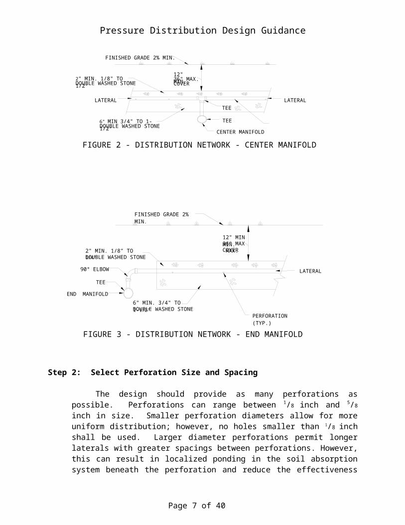
The distribution network should be laid out for conventional leaching trenches or leaching fields using manifolds and distribution laterals. Different configurations are possible. Central, end or off-center manifolds connecting the distribution laterals are options depending on site conditions (see Figures 2 and 3). Central manifolds are preferred, as they tend to minimize lateral length and manifold size. In order to minimize leakage from the perforations nearest the manifold, the laterals may be installed above the manifold elevation thus filling the entire manifold before discharge.
Page 3 of 31
FIGURE 1 – ALTERNATIVE LATERAL PERFORATION LAYOUTS
C
A B
C
A B
PERFORATIONS (TYP.)
LATERALS
<5 FT

Pressure Distribution Design Guidance
Provisions must be made to drain the laterals to prevent freezing using standard engineering practices. Care should be taken to prevent the entire lateral from draining into the soil absorption system from a single drainage perforation in the lateral.
Page 4 of 31


Pressure Distribution Design Guidance
Step 2: Select Perforation Size and Spacing
The design should provide as many perforations as possible. Perforations can range between 1/8 inch and 5/8 inch in size. Smaller perforation diameters allow for more uniform distribution; however, no holes smaller than 1/8 inch shall be used. Larger diameter perforations permit longer laterals with greater spacings between perforations. However, this can result in localized ponding in the soil absorption system beneath the perforation and reduce the effectiveness of the distribution of effluent within the system. Spacing between the perforations shall not exceed 5 feet. Air must be vented out of the laterals at the beginning of each dosing cycle. One option is to drill a perforation vent hole at the distal end of the elbow of the lateral sweep, below the stone aggregate, as shown in Figure 4. Laterals must drain to the soil absorption system or the pump chamber between dosings.
Page 6 of 31
FINISHED GRADE 2% MIN.
2" MIN. 1/8" TO 1/4"DOUBLE WASHED STONE
90° ELBOW
TEE
END MANIFOLD
6" MIN. 3/4" TO 1-1/2"DOUBLE WASHED STONE
12" MIN MIN.36" MAX MAX.COVER
LATERAL
PERFORATION (TYP.)
FIGURE 3 - DISTRIBUTION NETWORK - END MANIFOLD
FINISHED GRADE 2% MIN.
2" MIN. 1/8" TO 1/2"DOUBLE WASHED STONE
LATERALTEE
6" MIN 3/4" TO 1-1/2"DOUBLE WASHED STONE
12" MIN.36" MAX.COVER
LATERAL
CENTER MANIFOLD
TEE
FIGURE 2 - DISTRIBUTION NETWORK - CENTER MANIFOLD
Pressure Distribution Design Guidance
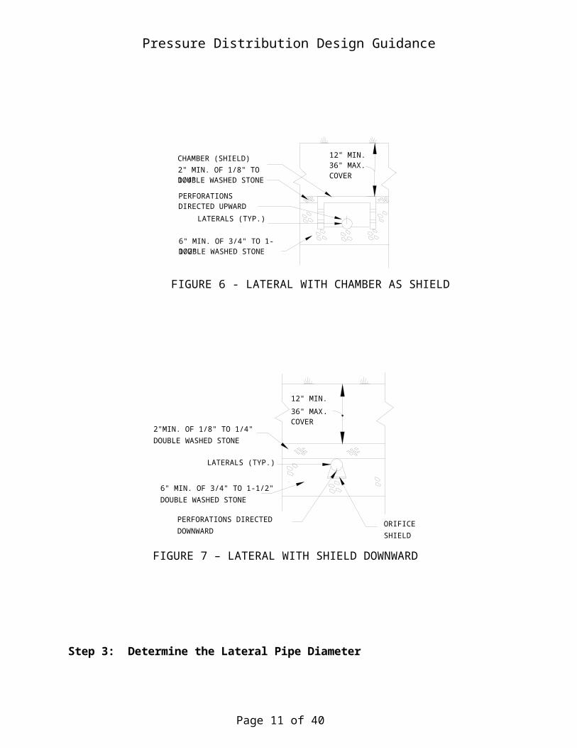
Acceptable configurations of the discharge perforations on any lateral in a system shall be located between the 10:00 o’clock position and the 2:00 o’clock position if oriented upward or between the 5:00 o’clock position and the 7:00 o’clock position if oriented downward.
A shield is required for any perforations located between the 10:00 o’clock and 2:00 o’clock positions and for any perforations located at the 6:00 o’clock position to reduce scouring of the soil above or below the laterals. Examples of acceptable shields include, but are not limited to, half diameter pipe, chambers and manufactured orifice shields (see Figures 5, 6 and 7).
Page 7 of 31
12" MIN.36" MAX.COVER
1/2 DIAMETER PIPE(SHIELD)
6" MIN. OF 3/4" TO 1-1/2"DOUBLE WASHED STONE
LATERALS (TYP.)
PERFORATIONSDIRECTED UPWARD
2" MIN. OF 1/8" TO 1/4"DOUBLE WASHED STONE
FIGURE 5 - LATERAL WITH SHIELD UPWARD
FIGURE 4 – END CLEANOUT DETAIL

Pressure Distribution Design Guidance
Step 3: Determine the Lateral Pipe Diameter
Figures 8A through 8G, Appendix B, can be used to determine the appropriate lateral diameter given perforation number and size, spacing and lateral length. These figures were developed by Otis (1982) based on the Hazen-Williams equation using a coefficient of Ch equal to 150. This is based on plastic pipe and allows for a maximum 10% head loss from the supply end to the distal end of the pipe.
Page 8 of 31
12" MIN.36" MAX.COVER
CHAMBER (SHIELD)2" MIN. OF 1/8" TO 1/4"DOUBLE WASHED STONE
PERFORATIONSDIRECTED UPWARD
LATERALS (TYP.)
6" MIN. OF 3/4" TO 1-1/2"DOUBLE WASHED STONE
FIGURE 6 - LATERAL WITH CHAMBER AS SHIELD
2"MIN. OF 1/8" TO 1/4"DOUBLE WASHED STONE
LATERALS (TYP.)
6" MIN. OF 3/4" TO 1-1/2"DOUBLE WASHED STONE
ORIFICESHIELD
PERFORATIONS DIRECTEDDOWNWARD
12" MIN.
36" MAX.COVER
FIGURE 7 – LATERAL WITH SHIELD DOWNWARD

Pressure Distribution Design Guidance
Step 4: Calculate the Lateral Discharge Rate
The lateral discharge rate equals the perforation discharge rate times the number of perforations in the lateral. Table 1 in Appendix C can be used to determine this rate or it can be determined directly from the orifice equation:
where q is the perforation discharge rate in gallons per minute (gpm), d is the perforation diameter in inches, and hd is the in-line distal head pressure in feet. (An orifice coefficient of 0.6 for sharp edged orifices is assumed). The value 11.79 is a dimensionalist coefficient that varies with the characteristics of the opening in the perforation. The total lateral discharge rate is q x N where N is the total number of perforations in the lateral.
The in-line distal head pressure is an important design
parameter. A minimum distal head pressure of 2.5 feet shall be
maintained to minimize variation in the system and provide a
construction tolerance; however, hd should not be so excessive as
to cause unnecessary friction losses in the network.
Step 5: Calculate the Manifold Size
Table 2 in Appendix C provides the diameter for a manifold that is to be uniform throughout its length. The diameter obtained is that which limits head loss from the manifold inlet to the distal end to no more than 10%. Telescoping manifolds may be used to reduce piping costs. The following equation (Otis, 1982) is used to calculate Fi values in each lateral segment:
where Qi is the flow in the manifold segment in gallons per minute. The F i values are empirical friction factors for each manifold segment. The value (9.8 x 10⁻⁴) is a coefficient that is based on friction losses as effluent passes through a plastic pipe. Using these values, the manifold diameter, Dm, is calculated by:
Page 9 of 31

Pressure Distribution Design Guidance
Where M is the number of manifold segments, Li is the length ith segment (i.e. lateral spacing) in feet, f is the fraction of the total head loss desired for that manifold segment or series of segments, and hd is the distal head pressure in the lateral in feet. To ensure that the head loss is less than 10%, f must be less than or equal to 0.1/ (total number of manifold segments) x number of the manifold segment for the section under design.
Step 6: Determine the Dose Volume
The minimum demand dose volume should be five to ten times the volume of the distribution lateral network. The nomograph in Appendix D can be used to calculate pipe volume. This volume should not exceed the required dose volume, calculated by dividing the average daily flow by the dosing frequency. When timed dosing is used, the dose volume can be reduced. If the manifold crown elevation lies below the lateral invert elevation, do not include the manifold pipe volume.
Step 7. Calculate Minimum Pump Discharge Rate
The minimum pump discharge rate is determined by adding the perforation (lateral) discharge rates.
Step 8. Calculate the Total Friction Losses
The total friction losses are the sum of losses in the force main and the discharge lateral network. The friction loss in the force main between the dosing chamber and the discharge lateral network is calculated based on the minimum discharge rate determined in Step 7. The appropriate equation from Hazen-Williams is:
where Ld is the length of the force main from the dosing chamber to the discharge lateral network inlet in ft, Dd is the pipe diameter (of the force main) in inches; and Qm is the discharge rate in gallons per minute. C h is equal to 150, which is the Hazen-Williams Friction Factor for plastic pipe. The value 3.55 is a dimensionless coefficient that is based on energy loss as effluent passes through a plastic pipe. Add the network losses that are equal to 1.31 hd, where hd is the distal head pressure
Page 10 of 31
Pressure Distribution Design Guidance
selected for the network. Include losses due to tees, gate valves, check valves, bends, etc. using standard friction factors for fixtures.
Step 9. Select the Pump Unit
The pump selection should follow standard engineering practice. The pump should be sized based on the total dynamic head (TDH) and the discharge rate required for the network. The TDH includes the static lift and appurtenant friction losses as well as the friction losses in the network computed in step 8. Manufacturer’s pump curves should be used to select the proper pump for the project.
Step 10. Size the Pump Chamber
The pump chamber must be designed to discharge the appropriate volume at the required rate with each dose. The chamber volume is determined based on the dosing volume from Step 6 plus a volume allowance for the drainage which may flow back to the chamber from the force main and manifold pipes when the pumping has ceased.
Title 5 requires that the dosing chamber have an emergency storage capacity above the high water alarm equal to the daily design flow volume of the system.
Title 5 also requires that all pump chambers be equipped with level controls and alarm switches. Level controls shall include pump on/pump off switches for single pump systems and pump off/lead pump on/lag pump on for dual pump systems. Dual pump systems must alternate the lead and lag pump every pump cycle. High water alarm switches shall be provided and shall be on a separate circuit from the pump level control.
A quick disconnect or other assembly to allow easy removal of the pump from the pump chamber should be incorporated into the design. A gate valve or globe valve may also be installed in the discharge line within the pump chamber or within a valve box outside of the chamber to allow final adjustments of pressure during the clear water test.
If effluent is to be pumped down hill, a ¼ inch siphon-breaker hole or anti-siphon valve shall be installed in the supply line in the pump chamber. This hole serves to break any vacuum in the system and prevents siphoning of effluent out of the chamber. If effluent is to be pumped uphill, a drain back hole shall be installed in the supply line (Figure 8) within the pump chamber to drain the manifold after pumping has stopped.
Page 11 of 31
INLET
PUMP ON
PUMP OFF
ALARMSTORAGE CAPACITY
PUMP CHAMBER
QUICK DISCONNECTSUPPLY LINE (FORCE MAIN)
CHECK VALVE (IF REQ'D)
SIPHON-BREAK ORDRAIN BACK HOLE
GATE OR GLOBE VALVE
RISER VALVE BOX (OPTIONAL)
LEVEL CONTROL (TYP.)
TO PRESSURE DISTRIBUTION NETWORK
FIGURE 8 - PUMP CHAMBER

Pressure Distribution Design Guidance
Title 5 requires that the pump and high water alarm must be placed on separate electrical circuits. Electrical connections shall be designed in accordance with the State Electrical Code. Power cords shall be connected to watertight NEMA Approved receptacles and not located inside the pump chamber.
Electrical wiring from the pump chamber to the facility shall meet the State Electrical Code. Surge protectors are recommended to protect the pump and controls.
310 CMR 15.000, Title 5, requires watertight construction to prevent surface water or groundwater from intrusion into system components.
Other Design Alternatives
This Guidance does not restrict the designer from using other designs that meet the basic requirements of Title 5 or this document. For example, the Department will allow the designer to divide the SAS into zones for pressure distribution provided that all zones are dosed before any zone is dosed again.
The designer may choose timed dosing versus demand dosing when appropriate. The designer must demonstrate that the design meets the objectives of this Guidance, which are to ensure wastewater is distributed evenly over an entire leaching area.
III. CONSTRUCTION:
The design and construction of the soil absorption system shall be in accordance with 310 CMR 15.000. The perforated pipe to be used as
Page 12 of 31

Pressure Distribution Design Guidance
laterals in the distribution network shall be either predrilled by the manufacturer or carefully drilled by the installer. The pipe, either furnished with the discharge orifices or drilled by the installer, shall be inspected for proper size and placement by the designer prior to installation.
The piping used for the distribution laterals should be laid out and cut to the design lengths. Perforations should be checked for correct design size and orientation. After installation, the positioning of the laterals should be rechecked. The sweep or elbow, with a removable end cap, should be placed at the distal end of each lateral for maintenance access and pressure testing (see Figure 4). Before the soil absorption system is backfilled, the sweeps should be placed inside a short length of 4 or 6 inch diameter pipe to provide easy access. The cap should be installed to within 3 inches of finished grade.
Prior to completion of backfilling, a clear water test shall be performed to verify the distal head pressure and confirm that each lateral is discharging equal flow within design tolerances. After the laterals are in place and tested and the orifice shields are installed, if required, the soil absorption system can be backfilled in accordance with 310 CMR 15.240 (9), (10) and (11).
To prevent solids carryover or clogging of the pressure distribution laterals or associated pumps and piping, Department approved effluent tee filters or approved equivalent technologies shall be installed prior to or within pump chambers of any pressure distribution system, unless an approved I/A technology is used that doesn’t require a filter.
Routine maintenance is necessary for a pressure distribution system to continue to work properly. The Department is developing an Inspection and Maintenance Guidance Document for use with pressure distribution systems.
IV. LIST OF REFERENCES:
The following references provide additional details and examples for the design of pressure distribution networks. It is highly recommended that the designer and approving authority obtain copies of these documents.
1. Otis, Richard J., 1982, “Pressure Distribution Design for Septic Tank Systems”, Journal of Environmental Engineering (ASCE), Vol. 108, No. EE1, February, 1982.
Page 13 of 31

Pressure Distribution Design Guidance
2. Otis, Richard J., “Onsite Wastewater Disposal Distribution Networks for Subsurface Soil Absorption Systems” National Small Flows Clearinghouse, West Virginia University, P.O. Box 6064, Morgantown, WV., 2506-6064.
3. USEPA, 1980, “Design Manual: Onsite Wastewater Treatment and Disposal Systems”, EPA 625/1-80-012, Cincinnati, Ohio
presdistguidance.4.18.02-approved.doc
Page 14 of 31

Pressure Distribution Design Guidance
APPENDIX ADESIGN EXAMPLE #1
A pressure network for a soil absorption system (SAS) is to be designed to receive an average daily flow of 550 gal for a 5 bedroom dwelling. The SAS is to be 25 ft x 40 ft. The pump chamber is to be located 50 ft from the network inlet.
Step 1. Lay out the Network
Two layouts would be suitable for this system. The distribution laterals can befed either by an end or a central manifold. An end manifold requires 5 laterals and acentral manifold requires 10 laterals, each one half the length of an end manifold lateral(see Figure 1-1). An end manifold will be used in this example.
Page 15 of 31
25 ft
50 ft
End Manifold
40 ft
Force Main
Pump Chamber
Lateral Network
FIGURE 1-1 END MANIFOLD CONFIGURATION FOR A SOIL ABSORPTION SYSTEM ON A LEVEL SITE
Soil Absorption System

Pressure Distribution Design Guidance
Step 2. Select Perforation Size and Spacing
Perforations ¼ inch in diameter with a maximum spacing of 5 ft (Other combinations may be as suitable.)
Step 3. Select Lateral Diameter
To insure uniform effluent application over the entire length of the lateral trench, the first and last perforations in the lateral will be located one-half the perforation spacing from either end of the lateral: Lateral length = 40 ft – (1/2 x 5) = 37.5 ft
From Figure 8a: Minimum diameter for a 37.5 ft lateral with 5 ft perforation spacing is 1 ¼ inches.
Step 4. Calculate the Lateral Discharge Rate
A minimum in-line pressure of 2.5 ft is to be used. From Table 1: a ¼ inch perforation will discharge 1.17 gpm
No. of Perforations/Lateral = 40/5 = 8
Lateral Discharge Rate = 8 x 1.17 gpm = 9.4 gpm
Step 5. Calculate the Manifold Size
The manifold diameter is to be uniform along its length to simplify construction.
Manifold length 4 x 5 ft = 20 ft
From Table 2, an end manifold with a lateral discharge rate of 9.4 gpm and lateral spacing of 5 ft can have a maximum length of 20 ft for a 2 inch diameter manifold or 44 ft for a 3 inch diameter manifold. Use a 3 inch diameter manifold.
Step 6. Determine Dose Volume
The crown elevation of the manifold should be located below the lateral invert elevation. The manifold and delivery line drain back into the pump chamber at the end of each dose. Therefore, the minimum dose volume is based on the lateral pipe volume only. The minimum dose volume is 5 to 10 times the total lateral volume.
Total length of 1 ¼ inch laterals = 5 pipes x 40 ft = 200 ft Area 1 ¼ inch laterals = (r)2 = (0.052)2 = 0.0085 sf Total pipe volume = 0.0085 sf. x 200 ft = 1.7 cf
Page 16 of 31

Pressure Distribution Design Guidance
1.7 cf x 7.48gal/cf = 12.7 gal
Minimum Dose Volume of 5 to 10 times the pipe volume 12.7 gal (5 to 10) = 64 to 127 gal Dose as frequently as possible, e.g., 8 doses per day (dpd) 550 gpd / 8 dpd = 69 gal per dose (other combinations may be just as suitable)
Since the manifold and delivery line will drain back to the pump chamber, the pumping volume must be increased to equal the volume in the manifold and delivery line. The volume increase is equal to 20 ft of 3 inch manifold pipe volume and 50 ft of 2 inch delivery pipe of 9 gallons. Therefore:
Pumping Volume = dose vol + drain back vol = 69 gal + (7.4 gal + 3.2 gal) = 79.6 gal
Step 7. Calculate the Minimum Discharge Rate
Minimum Discharge Rate = 9.4 gpm / lateral x 5 laterals = 47 gpm
Step 8. Calculate Total Friction Loss
Ld = 50 ft (length of force main) Ch = 150 (If plastic pipe) Dd = 2 inch (diameter of force main) Qm = 47 gpm (discharge rate)
Friction Loss = Ld(3.55Qm/ChDd2.63)1.85
= 50 ft (3.55 x 47 / 150 x 2 2.63)1.85
= 2.08 ft Network Losses = 1.31 hd = 1.31 x 2.5 ft = 3.28 ft
Total Losses = 2.08 ft + 3.28 ft = 5.36 ft (round up and use 6 ft) (Losses in the pump chamber and the network due to tees, gate valves, check valves, bends, etc., must also be added to total losses.)
Step 9. Select the Pump Unit
Total Pumping Head = Static head + Friction Losses
If the pump off elevation in the pump chamber is 5 ft below the lateral invert elevation, the total pumping head is:
5 ft + 6 ft (friction losses from Step 8) or 11 ft
Page 17 of 31

Pressure Distribution Design Guidance
Using head-discharge curves provided by the manufacturer, a pump able to discharge at least 47 gpm against 11 ft of head is selected.
Step 10. Size the Pump Chamber
Only one pump will be used on systems with a daily design flow of less than 2,000 gallons per day. A reserve volume equal to one day’s average flow is necessary in case of pump failure. Therefore, a volume of 79.6 gallons (dose volume + drain-back volume) + 550 gallons (average daily flow) or 630 gallons, must be provided between the pump off switch elevation and the pump chamber invert elevation. The high water alarm switch is located just above the pump on switch.
Page 18 of 31

Pressure Distribution Design Guidance
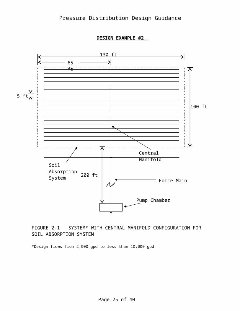
DESIGN EXAMPLE #2
A pressure distribution network for a soil absorption system (SAS) is to be designed to receive an average daily flow of 8,400 gal. The SAS will be 100 ft x 130 ft. The pump chamber is to be located 200 ft from the network inlet.
Step 1. Lay Out a Network
Page 19 of 31
FIGURE 2-1 SYSTEM* WITH CENTRAL MANIFOLD CONFIGURATION FOR SOIL ABSORPTION SYSTEM
*Design flows from 2,000 gpd to less than 10,000 gpd
Soil Absorption System
Force Main
Central Manifold
5 ft
100 ft
130 ft
65 ft
Pump Chamber
200 ft

Pressure Distribution Design Guidance
A central manifold configuration is selected as shown in Figure 2-1.
Step 2. Select Perforation Size and Spacing
Perforations are to be ¼ inch diameter spaced 5 ft apart.
Step 3. Select Lateral Diameter
From Figure 8a: 1 ½ inch laterals are required
Step 4. Select Lateral Discharge Rate
A minimum in-line pressure of 2.5 ft is to be used.
From Table 1: Perforation Discharge Rate = 1.17 gpm
No. of Perforations/lateral = 65/5 = 13
Lateral Discharge Rate = 13 x 1.17 = 15 gpm/lateral
Step 5. Calculate Manifold Size
This system is too large to determine the manifold size from Table 2. Therefore, the manifold diameter is determined based on the flow rate necessary to feed the distribution laterals and friction factors using standard hydraulic calculations. The designer must first divide the manifold network of 40 laterals (20 on each side of the manifold) spaced five feet apart resulting in 19 manifold segments (100/5 – 1). Individual friction factors (Fi ) in each segment are determined from:
where Qi is the flow in each manifold segment. The general equation for manifold diameter is:
where Dm is the manifold diameter, Li is the length of the manifold segment (in feet), Fi is the friction factor in the manifold segment, f is the fraction of the total head loss desired in that segment and hd is the desired distal head pressure in the system. Since the designer needs to limit head loss throughout the manifold to
less than 10%, f must be less than or equal to 0.1.
Page 20 of 31

Pressure Distribution Design Guidance
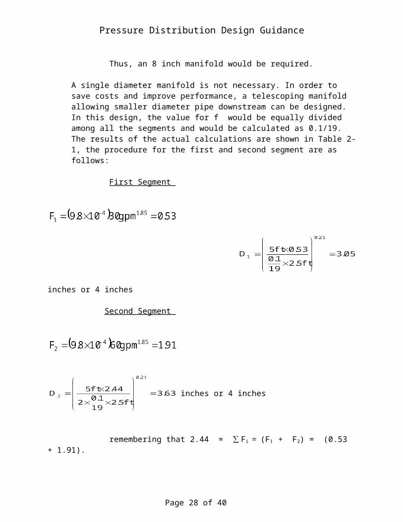
A single diameter manifold can be calculated by:
= 7.8 inches or an 8 inch pipe
Thus, an 8 inch manifold would be required.
A single diameter manifold is not necessary. In order to save costs and improve performance, a telescoping manifold allowing smaller diameter pipe downstream can be designed. In this design, the value for f would be equally divided among all the segments and would be calculated as 0.1/19. The results of the actual calculations are shown in Table 2-1, the procedure for the first and second segment are as follows:
First Segment
inches or 4 inches
Second Segment
inches or 4 inches
remembering that 2.44 = ∑ Fi = (F1 + F2) = (0.53 + 1.91).
Table 2-1 Results of Calculations to Determine Manifold Segment Diameters
Segment Qi, Dm , Segment Qi, Dm ,
Number gpm Fi inches Number gpm Fi inches_______________________________________________________________________________ _____ 1 30 0.53 0.53 3.05 11 330 44.72 195.58 6.37
Page 21 of 31

Pressure Distribution Design Guidance
2 60 1.91 2.44 3.62 12 360 52.53 248.11 6.58 3 90 4.04 6.48 4.09 13 390 60.91 309.02 6.77 4 120 6.88 13.36 4.48 14 420 69.86 378.88 6.96 5 150 10.40 23.76 4.83 15 450 79.37 458.25 7.14 6 180 14.57 38.33 5.14 16 480 89.44 547.69 7.31 7 210 19.38 57.71 5.42 17 510 100.05 647.74 7.48 8 240 24.81 82.52 5.68 18 540 111.21 758.96 7.63 9 270 30.85 113.37 5.93 19 570 122.91 881.87 7.79 10 300 37.49 150.86 6.16 Inlet 600 135.15 1017.01 7.94
Remember that Qi in Column (2) is based on 15 gpm per lateral and that each segment has two laterals.
Thus, manifold segments: 1-2 are 4 inch segments 3-9 are 6 inch segments 10-19 are 8 inch segments
Step 6. Determine Dose Volume The crown of the manifold is to be located below the lateral inverts. The manifold and delivery lines drain back into the pump chamber at the end of each dose. Therefore, the minimum dose volume is based on the lateral pipe volume only. The minimum dose volume is 5 to 10 times the total pipe volume.
Minimum Dose Volume = Area 1 ½ inch lateral x lateral length x No. of Laterals x (5 to 10) = x 65 ft x 40 x (5 to 10) x 7.48 gal/cf = 1190 to 2387 gallons
Dose leaching field as frequently as possible. e.g., use 1200 gal/dose
Doses per day =
Must add volume draining back to pump chamber from manifold and delivery pipe to volume in chamber. 4 inch manifold = 10 ft 6 inch manifold = 35 ft 8 inch manifold = 55 ft (0.333)2 = 0.35 sf x 55 ft = 19.2 cf
200 ft of 1 1/5 in delivery pipe =200 x (0.0625)2 = 2.4 cf 0.87cf + 6.8cf + 19.2 cf + 2.4 cf = 29.3 cf 29.3 cf x 7.48 gal/cf = 220 gal draining back to pump chamber
Minimum pump volume = dose volume + drain back volume = 1200 gal + 220 gal = 1440 gal
Step 7 Calculate Minimum Discharge Rate
Minimum Discharge Rate = 15 gpm/lateral x 40 laterals = 600 gpm
Step 8 Calculate Total Friction Loss
Page 22 of 31

Pressure Distribution Design Guidance
Ld = 200 ft Ch = 150 (delivery pipe is plastic) Dd = 1 ½ inch Qm = 600 gpm Delivery Loss (200 ft of 8 inch) = Ld(3.55Qm / ChDd
2.63)1.85 = 200 (3.55 x 600 / 150 x 82.63)1.85 = 1.09 ft
Network Losses = 1.31 hd = 1.31 x 2.5 = 3.28 ft Total Losses = 3.28 ft + 1.09 ft = 4.37 ft (round up and use 5 ft) (Losses due to tees, valves, bends, etc., must also be added to total losses.)
Step 9. Select the Pump Unit(s)
In this instance, two alternating pumps will be used. Total Pumping Head = Static Head + Friction Losses If the pump shut-off level in the pump chamber is 5 ft below the lateral inverts, the total pumping head is:
5 ft + 5 ft (friction losses from Step 8) or 10 ft
Using head-discharge curves provided by the manufacturer, select a pump able to discharge at least 600 gpm against 10 ft of head.
Step 10. Size the Pump Chamber
There will be two alternating pumps, a reserve volume equal to one day’s average flow is necessary in case of electrical outages. Therefore, a volume of 1,440 gallons (dose volume + drain back volume) + 8,400 gallons (average daily flow) or 9,840 gallons must be provided between the pump off switch and the pump chamber invert. The high water alarm switch is located just above the pump on
switch, the backup (lag) pump on switch is located just above the high water alarm switch.
Page 23 of 31

Pressure Distribution Design Guidance
APPENDIX B
Page 24 of 31
FIGURE 8a & 8b: Minimum Lateral Diameter vs. Perforation Spacing & Lateral Length. (Figure 8a can be used for 1/8 inch diameter perforations).
Pressure Distribution Design Guidance
FIGURE 8c & 8d: Minimum Lateral Diameter vs. Perforation Spacing & Lateral Length
Page 25 of 31

Pressure Distribution Design Guidance
FIGURE 8e & 8f: Minimum Lateral Diameter vs. Perforation Spacing & Lateral Length
Page 26 of 31

Pressure Distribution Design Guidance
FIGURE 8g: Minimum Lateral Diameter vs. Perforation Spacing & Lateral Length
Page 27 of 31
Pressure Distribution Design Guidance
APPENDIX C
NOTE: Figures for 1/8 inch perforation diameters compiled by P. Spath, B. Dudley, (2001)
Page 28 of 31

Pressure Distribution Design Guidance
Page 29 of 31


Pressure Distribution Design Guidance
Page 31 of 31