this is your software security access key: do not lose it · 1 this is your software security...
TRANSCRIPT

1
This is Your Software Security Access Key:
DO NOT LOSE IT !
This security device must be plugged into the notebook
computer’s USB port or the spare USB port on your interface
box whenever the FREEDOM Tool Software is to be run.

2
List of Trademarks
Windows is a trademark / product of Microsoft Corporation. Microsoft is a registered trademark. DMC-I is a registered trademark of Thyssen Elevator Systems, Inc. WORLD electronics, the WORLD electronics' logo, FREEDOM Tool, and FREEDOMWare are registered trademarks of WORLD electronics Sales and Service, Inc.
Copyright © 1993-2012 by WORLD electronics®. All rights reserved. Printed in the United States of America. Except as permitted under the United States Copyright Act of 1976, no part of this publication may be reproduced or distributed in any form or by any means, or stored in a data base or retrieval system, without the prior written permission of WORLD electronics. Further, this publication and features described herein are subject to change without notice.

3
Introduction ....................................................................................................................................4 FREEDOM Tool® Features .......................................................................................................4 Minimum Hardware and Software Requirements ......................................................................4 How to contact WORLD electronics ..........................................................................................5 Package Contents (Hardware components)..............................................................................6 DMC-I USB Interface Box ...................................................................................................6 Information on connecting to the elevator system ........................................................6 Security Key (6015.0014): ...................................................................................................7 Installation CD (6015.0002):................................................................................................7 Installing the USB DMC-I Software Module ...............................................................................8 Installing the USB Drivers ........................................................................................................13
Executing the FREEDOM Tool Shell Program ...........................................................................23 Executing the FREEDOM Tool Shell Program (Windows 9 5, 98, Me) .....................................25
The DMC-I Software Module (Serial Port and USB Vers ions) ..................................................27
General Description .....................................................................................................................30 Car Logic Controller (CLC) Window ........................................................................................31 Adjustment / Timers Window ............................................................................................34 Subsystem I/O Information Display Window .....................................................................36 Selector Window......................................................................................................................38 Selector Adjustment Window ............................................................................................40 Selector Subsystem I/O Information Display Window.......................................................42 Hoistway Setup..................................................................................................................44 Selector Parameters..........................................................................................................48 Front and Rear Door Window..................................................................................................51 Door Adjustment Window..................................................................................................54 Door Subsystem I/O Information Display Window ............................................................56 Door Startup Sequence.....................................................................................................58 Door Parameters ...............................................................................................................61
File .................................................................................................................................................64 Save.........................................................................................................................................65 Restore ....................................................................................................................................66 Exit ...........................................................................................................................................68
DMC File Utility ............................................................................................................................68 Start-Up....................................................................................................................................68 General Description .................................................................................................................69 Load File............................................................................................................................69 Print File ............................................................................................................................70 Save File............................................................................................................................70 Create Text File.................................................................................................................72 Adjustment Types..............................................................................................................72 Exit.....................................................................................................................................73
Subsystem I/O Bit Information...................... ..............................................................................74 CLC..........................................................................................................................................74 Selector....................................................................................................................................80 Front and Rear Door ................................................................................................................81
DMC-I Adjustment / Timer Worksheet ................. .......................................................................84

4
Introduction:
The FREEDOM Tool is a sophisticated software tool which allows the operator to service various elevators and elevator control systems. The software allows the operator to simultaneously view independent operations within the elevator system by opening windows to those systems / operations of interest. The selected windows may then be left open during the maintenance / repair session and accessed when desired.
This User’s Guide and Reference, part number 7502.9028, has been written to specifically target the Dover DMC-I elevator control system. All references to “FREEDOM Tool® ” or “FREEDOMWare®” throughout the manual implies that it pertains solely to the Dover DMC-I Software Module.
FREEDOM Tool Features :
The FREEDOM Tool is a Graphical User Interface (GUI) and provides all the functions necessary to service the Dover DMC-I elevator system. The software runs under Microsoft’s Windows operating system and provides the following features:
• A Graphical User Interface which makes it easy to access various printed circuit board modules comprising the Dover DMC-I elevator system to be diagnosed.
• System adjustment parameters for the elevator system being diagnosed are presented in terms that are the industry standards within the elevator industry.
• Operating information pertinent to a particular elevator site may be “Saved” or “Restored” at any time through the use of the “File” command within the Main selection window.
Minimum Hardware and Software Requirements :
The software is provided as a package by WORLD electronics and is installed on a PC running with Microsoft Windows based Operating systems which have the following characteristics:
• A Pentium or equivalent microprocessor.
• Windows 98, Windows XP/2000, or Windows Vista Operating System.
• CD-ROM Drive
• Mouse, Trackball, or other pointing device.
• 1 USB (Universal Serial Bus) Port
The FREEDOMWare is not capable of being executed without a sophisticated security key that is to be connected to the USB port of the computer or the spare USB port on the interface box at the time of the FREEDOM Tool execution.
A WORLD electronics “Dover DMC-I USB Interface” (7502.9032) communications box is required. This interface box provides a signal level conversion between the computer and the Dover DMC-I elevator system which allows them to communicate with one another.

5
How to contact WORLD electronics:
If you are having any problems operating the FREEDOM Tool, feel free to contact us at the following location. We value you as a customer and welcome any comments concerning the use of the FREEDOM Tool.
WORLD electronics Phone: 1-800-523-0427 3000 Kutztown Road Phone: (610) 939-9800 Reading, PA 19605-2617 Fax: (610) 939-9895
E-mail:
Elevator Sales: [email protected]
Service: [email protected]
FREEDOM Tool: [email protected]
When calling WORLD electronics for assistance, have your product serial number, the model computer being used, operating system type, and the error description ready.

6
Package Contents (Hardware Components):
DMC-I USB Interface Box (7502.9032):
The DMC-I USB Interface Box provides the communication interface between the DMC-I smart PCB’s and the Notebook Computer on which the FREEDOMWare is loaded. Without this device, the USB DMC-I FREEDOMWare module will not work.
Figure 1
The DMC-I USB Interface Box as shown in Figure 1 is comprised of a black box with a 25 pin male D-shell connector on one end marked Elevator Connection . On the other end of the interface box are two(2) USB Ports labeled USB to PC and Security Key . Looking at the label found on the Interface Box, several things can be determined. Among these are: 1) the name of the Interface Box (FREEDOM Tool Interface for Dover DMC-I Products ), 2) connection point for the elevator system, 3) connection point for the Security Key, and 4) connection point for the Notebook Computer. The Interface Box may be plugged into the elevator system at any time, but the connection to the Notebook Computer must be made before the software is to be run.
NOTE: A one(1)-time installation procedure must be followed on each Notebook PC using the USB Interface Box in order for the interface and security key to function properly in conjunction with the software. This installation procedure is described in detail in the section titled Installing the USB Device Drivers on Page 13.
Information on connecting to the elevator system:
The connector which interconnects the FREEDOM Tool with the DMC-I elevator system is physically located in four specific locales. They are as follows:
A. In the machine room inside the control panel there resides a 25 pin D connector with the legend SINGLE.
B. Inside the car behind the control panel there resides a 25 pin D connector with the legend SINGLE.
C. On top of the car there resides a 25 pin D connector on the top of the Selector box. This connector has no particular legend. Depending on the model of the elevator system the connector may or may not be visible.
D. On top of the car there resides a 25 pin D connector on the front side of the Door Operator. This connector has no particular legend.

7
Security Key (6015.0014):
Figure 2
The FREEDOMWare can be loaded on any computer, but only one (1) instance of the program can be run at any single time. To ensure this, WORLD electronics protects itself and its FREEDOMWare by utilizing a sophisticated security device that must be plugged into a Notebook Computer USB port or the USB port on the interface box labeled Security Key prior to operating the FREEDOMWare (Figure 2). If the security key is plugged into the USB Interface Box, then the Interface Box must be plugged into the USB port of the Notebook PC. This security key is unique to every FREEDOM Tool and must be plugged into the Notebook PC while the FREEDOMWare is running. The security key is not to be confused with the communications interface box. The communications interface box is easily identifiable by its label located on its face.
WARNING! - It is extremely important that this secu rity key is not lost. The replacement value of this device is equal to the dollar value of the FRE EDOM Tool software module(s) purchased from WORLD electronics. This cost is in thousands of do llars. Please take the steps necessary to safeguard yourself against loss of the security dev ice.
Note: All security keys are pre-programmed with a 4 5 day expiration date. Please contact WORLD electronics after payment is made in order to get a “renew code”. This will eliminate the expiration date and allow unlimited use of your new FREEDOM Tool.
Installation CD (6015.0002):
All software related to the operation of the FREEOM Tool is located on the FREEDOMWare Installation CD. To access the installation program located on the CD-ROM, simply insert the FREEDOMWare Installation CD into the Notebook PC’s CD-ROM Drive.

8
Figure 3
Upon insertion the installation program should launch allowing the user access to the installation routines and reference manuals for all available FREEDOMWare Modules (Figure3). Please refer to the section labeled Installing the USB DMC-I Software Module for instructions on installing the USB DMC-I Software Module.
Installing the USB DMC-I Software Module:
IMPORTANT: DO NOT PLUG THE DMC-I INTERFACE OR SECU RITY KEY INTO THE NOTEBOOK COMPUTER UNTIL STEP 8 OF THIS INSTALLATION IS REACH ED. STEP 8 WILL GIVE DETAILS ON PROPERLY CONNECTING THE HARDWARE DEVICES AND PROPER LY INSTALLING THEIR RESPECTIVE HARDWARE DRIVERS!
The installation procedure for the USB DMC-I Software Module is described as follows:
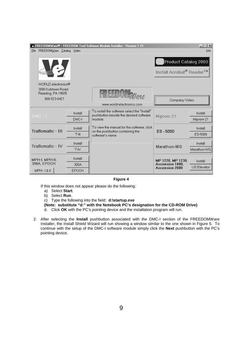
1. Insert the FREEDOMWare Installation CD into the Notebook PC’s CD-ROM Drive. After approximately 10 seconds a window will appear titled FREEDOMWare – FREEDOM Tool Software Module Installer . Please refer to Figure 4.
9
Figure 4
If this window does not appear please do the following: a) Select Start . b) Select Run . c) Type the following into the field: d:\startup.exe (Note: substitute “d:” with the Notebook PC’s desi gnation for the CD-ROM Drive) d. Click OK with the PC’s pointing device and the installation program will run.
2. After selecting the Install pushbutton associated with the DMC-I section of the FREEDOMWare Installer, the Install Shield Wizard will run showing a window similar to the one shown in Figure 5. To continue with the setup of the DMC-I software module simply click the Next pushbutton with the PC’s pointing device.

10
Figure 5
3. After selecting Next , a Registration Info window will appear as in Figure 6. In this window the user will need to fill in the fields beside User Name: , Company Name: , and Serial Number: . The Serial Number can be obtained from a label located on the DMC-I Module’s Security Key. A second location where the serial number can be found is the side of the DMC-I Software Module’s Product Box.
Figure 6
4. After entering all the information into the 3 separate fields, the Next pushbutton will appear allowing the installation to continue (Refer to Figure 7). Select Next to continue with the installation.

11
Figure 7
5. The Ready to Install the Program window will now appear as in Figure 8. This window informs the user that the installation is ready to begin and instructs the user to select the Install pushbutton to begin the software installation process. At this time select the Install pushbutton with the PC’s pointing device.
Figure 8
6. The Setup Status window will appear (Figure 9) showing the user the status of the installation procedure. Immediately upon completion of copying the FREEDOM Tool software, the Installation program will begin installing the necessary files for the Security Key Device. Upon the completion of the Security Key Software Installation a window similar to Figure 10 will appear. This window informs

12
the user that the Az-Tech Device Drivers Setup is complete and the user should select Finish to complete the installation. At this time select the Finish pushbutton on the screen to complete the Az-Tech Device Driver Setup and continue with the FREEDOMWare Installation.
Figure 9
Figure 10
7. After a brief delay another window will appear(Figure 11) informing the user that the FREEDOMWare installation is complete and instructs the user to once again select the Finish pushbutton to complete the FREEDOMWare installation.

13
Figure 11
Installing the USB Device Drivers
1. AT THIS TIME PLUG THE USB DMC-I INTERFACE BOX INTO THE USB PORT ON THE NOTEBOOK PC. DO NOT PLUG THE USB SECURITY KEY INTO ANY PORT (INC LUDING THE ONE LOCATED ON THE USB INTERFACE BOX) AT THIS TIME.
2. A Found New Hardware Wizard window should appear**. See Figure 12. In this window click, one time, on the circle beside No, not this t ime . The Circle should have a Black Dot in its center. Click the Next pushbutton to continue.
**NOTE: On some operating systems, this operation will complete automatically without user interaction. In this case a popup bubble will appear near the right side of the taskbar saying that your hardware has been successfully installed.

14
Figure 12
3. The window shown in Figure 13 should appear. In this window, click one time on the circle beside Install from a list or s pecific location (Advanced) so that it has a black dot in its center. After completing this task, select Next to continue with the Driver Installation.
Figure 13
4. After selecting list or specific location, the New Hardware Wizard window will appear as seen in Figure 14. In Figure 14, the user must make sure the following items are selected with a black dot or check mark: Search for the best driver in these locations , Include this location in the search: . When Include this location in the search: is checked the pushbutton labeled Browse should be enabled. At this time select the Browse pushbutton with the PC’s pointing device.

15
Figure 14
5. When the Browse pushbutton is selected, a Browse for Folder will appear as in Figure 15. Do the following in this window:
a) Click on My Computer . b) Click on Local Disk (C: ) . c) Click on Nellie . d) Click on SiLabs . e) Click on MCU. f) Click on Cp210x . g) Click on WIN. h) Click on OK pushbutton.
Figure 15

16
6. After the OK pushbutton is selected in the Browse For Folder window, the input focus will once again be upon the Found New Hardware Wizard window requesting the user to choose the search and installation options. Looking at the field underneath Include this location in the search: should be the directory path: C:\nellie\SiLabs\MCU\CP210x\WIN . Refer to Figure 16. To continue, press the Next pushbutton found at the bottom of this window.
Figure 16
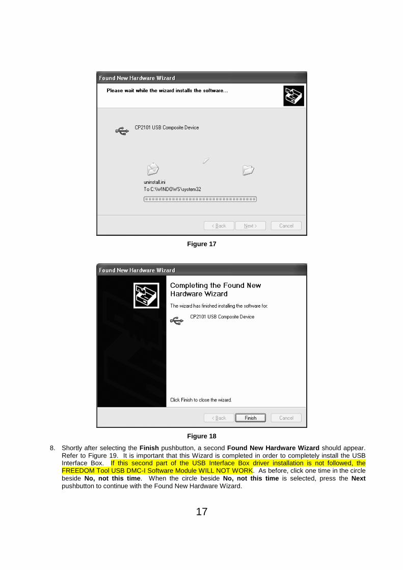
7. The Wizard will look for the necessary drivers for the CP2102 USB to UART Bridge Controller and Install them (See Figure 17). When the installation is complete and successful the Completing the Found New Hardware Wizard will appear (Figure 18) showing the user the installation status. Click the Finish pushbutton to complete the installation.
17
Figure 17
Figure 18
8. Shortly after selecting the Finish pushbutton, a second Found New Hardware Wizard should appear. Refer to Figure 19. It is important that this Wizard is completed in order to completely install the USB Interface Box. If this second part of the USB Interface Box driver installation is not followed, the FREEDOM Tool USB DMC-I Software Module WILL NOT WORK. As before, click one time in the circle beside No, not this time . When the circle beside No, not this time is selected, press the Next pushbutton to continue with the Found New Hardware Wizard.

18
Figure 19
9. After selecting Next in the Windows represented in Figure 19, the Window will update as shown in Figure 20. In this window the user should select the circle beside the text Install from a list or specific location (Advanced) . As commanded at the bottom of the window, select the Next pushbutton to continue with the Found New Hardware Wizard .
Figure 20
10. As it did in the first section of the USB Interface Driver Installation the window now updates allowing the user to select where the driver files will come from. Refer to Figure 21. The field underneath Include this location in the search: should now show the path C:\nellie\SiLabs\MCU\CP210x\WIN. If it does,

19
continue by selecting the Next pushbutton. If the path is not located in the text field beneath Include this location in the search: please refer to Step 5 of this installation procedure in order to get that path displayed. Select Next to continue with the Found New Hardware Wizard.
Figure 21
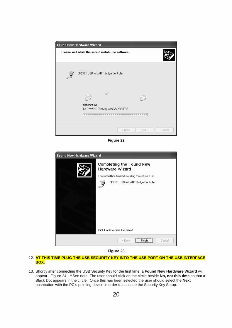
11. Upon selecting Next, the Found New Hardware wizard will continue with the installation of the remaining drivers for the DMC-I USB Interface box (Figure 22). Upon completion of the driver installation, the window will update similar to the one shown in Figure 23. The window in Figure 23 informs the user that the driver installation was successful and that the Finish pushbutton should be pressed to complete the Found New Hardware Wizard Installation. At this time, select Finish to complete the DMC-I USB Interface Box installation.
20
Figure 22
Figure 23
12. AT THIS TIME PLUG THE USB SECURITY KEY INTO THE USB PORT ON THE USB INTERFACE BOX.
13. Shortly after connecting the USB Security Key for the first time, a Found New Hardware Wizard will appear. Figure 24. **See note. The user should click on the circle beside No, not this time so that a Black Dot appears in the circle. Once this has been selected the user should select the Next pushbutton with the PC’s pointing device in order to continue the Security Key Setup.

21
**NOTE: On some operating systems, the following operations may occur automatically without any user intervention. When completed, a popup bubble will appear on the right side of the taskbar stating that Hardware has been installed successfully.
Figure 24
14. The next window in the Security Key Setup informs the user that the wizard will help install the necessary software for USB KEY. Refer to Figure 25. In this window make sure the circle beside Install the software automatically (Recommended) has a black dot. With the Black Dot in place in the desired location, select the Next pushbutton to continue with the Security Key Installation.
Figure 25
22
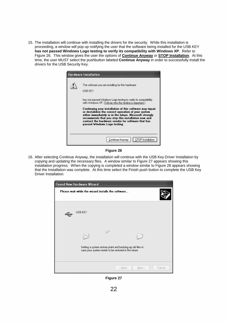
15. The installation will continue with installing the drivers for the security. While this installation is proceeding, a window will pop up notifying the user that the software being installed for the USB KEY has not passed Windows Logo testing to verify its c ompatibility with Windows XP . Refer to Figure 26. This window gives the user the options of Continue Anyway or STOP Installation . At this time, the user MUST select the pushbutton labeled Continue Anyway in order to successfully install the drivers for the USB Security Key.
Figure 26
16. After selecting Continue Anyway, the installation will continue with the USB Key Driver Installation by copying and updating the necessary files. A window similar to Figure 27 appears showing this installation progress. When the copying is completed a window similar to Figure 28 appears showing that the Installation was complete. At this time select the Finish push button to complete the USB Key Driver Installation.
Figure 27

23
Figure 28
Executing the FREEDOM Tool Shell Program (USB Versi on) :
The start up procedure of the WORLD electronics’ FREEDOM Tool is described as follows:
1. Make sure the security key is installed on the USB port of the computer or the spare USB port located on the interface box. If the security key is plugged into the USB port located on the DMC-I USB Interface Box, then make sure the interface box is plugged into the USB port on the Notebook PC.
2. From the Microsoft Windows Desktop Screen select the FREEDOM Tool Icon by using the pointing device to position the cursor directly over the FREEDOM Tool Icon and double clicking the pointing device button. Refer to Figure 29.

24
Figure 29
3. Double clicking the FREEDOM Tool Icon will run the main FREEDOM Tool Application software. This software allows the user to select the various FREEDOMWare module that WORLD electronics has available. Refer to Figure 30.
Figure 30
NOTE: Only installed FREEDOMWare software will run. If the module selected is not installed a window will appear as in Figure 31 informing the user that the Module is not installed and to contact WORLD electronics. If this window appears and the software was purchased from WORLD electronics, then contact a member of WORLD electronics’ technical support staff. If the software was not purchased, it can be purchased by contacting WORLD electronics’ Sales Staff. The contact information on both of these departments can be found on Page 5 of this manual.

25
Figure 31
4. In order to run the USB DMC-I Software Module the user would need to select Dover from the menu. Refer to Figure 32. After Dover is selected the user is presented with choices of USB, Serial Port, DMC File Utility, Traflomatic III, Traflomatic IV .
Figure 32
5. The next item to be selected in order to run the USB DMC-I Software Module is the menu choice USB. In the USB category there is only one(1) software listed. Refer to Figure 33.
Figure 33
This software is the USB DMC-I Module. In order to run the USB DMC-I Module, position the Notebook PC’s pointing device over top of the choice USB DMC-I Module and click one time. If the module is installed, the software will begin running at this time.
Executing the FREEDOM Tool Shell Program: (Serial Port – RS 232) Windows 95, 98 and Me ONLY! :
The start up procedure of the WORLD electronics’ FREEDOM Tool is described as follows:
1. From a power down condition, make sure the security key is installed on the parallel port of the computer.
2. Turn on the computer and allow the Windows operating system to become operational. From the Desktop either double click with the pointing device on the FREEDOM Tool icon, or select the Start Menu button then FREEDOM Tool Folder and then FREEDOM Tool . Refer to Figure 34.
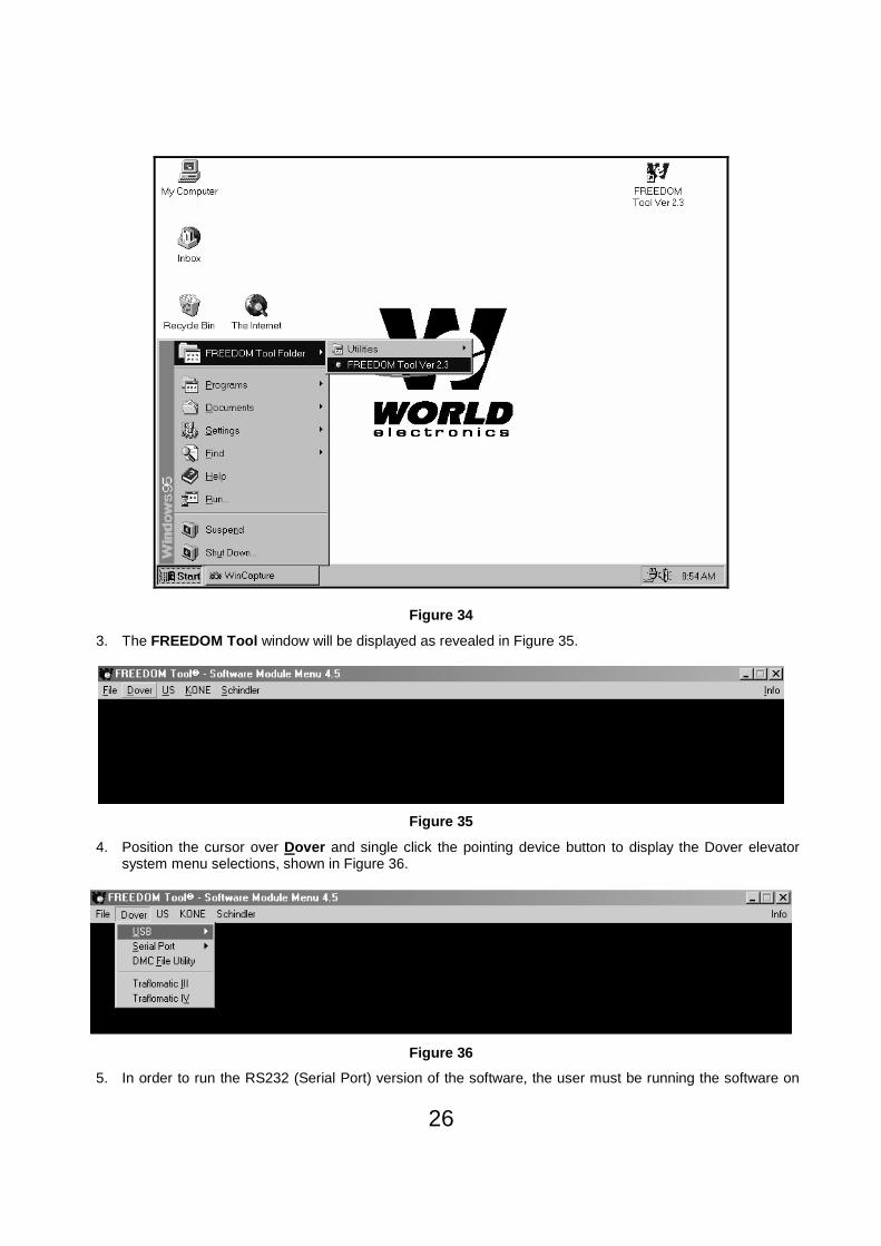
26
Figure 34
3. The FREEDOM Tool window will be displayed as revealed in Figure 35.
Figure 35
4. Position the cursor over Dover and single click the pointing device button to display the Dover elevator system menu selections, shown in Figure 36.
Figure 36 5. In order to run the RS232 (Serial Port) version of the software, the user must be running the software on

27
an older Microsoft Windows OS such as Windows 95, Windows 98, or Windows Me and the PC must have at least one(1) Serial and Parallel(Printer) port. If these requirements are met, then the user can continue by selecting Serial Port from the drop down portion of the Dover menu selection. Doing this will provide another menu selection as viewed in Figure 37.
Figure 37
6. The FREDOM Tool Software Module Menu window, as shown in Figure 37 gives the user the choices of DMC-I - 675A and DMC I -675D/E . Position the cursor over the version desired and single click with the pointing device button. The DMC-I 675 version of software may be determined by examining the EPROM integrated circuits physically located on the Car Logic Controller (CLC) printed circuit board as referenced by the silk-screened legends “U26" / “M4", “U27" / “M3", “U28" / “M2", “U29" / “M1". If the EPROM has label 675A## use the DMC I - 675A��������. Otherwise if the EPROM has the label 675D## or 675E## please use the DMC I - 675D/E��������.
The DMC-I Software Module (Serial Port and USB Vers ions):
1. When the selected DMC software module begins to run, a window similar to the one seen in Figure 38 will appear. Figure 38 allows the users to choose the serial port used on their notebook computer. If the notebook computer being used has a serial port designated as COM 1, the user would select the pushbutton COM 1 and then select OK. The pushbutton labeled COM 1 would now be in a pressed state. In the event the notebook computer assigns its serial port the value COM 2, the user would move the pointing device arrow over the COM 2 button and click once with the mouse button. It is important to note that the USB software will pre-select the assigned serial port if the DMC-I USB Interface box is plugged into the USB port of the Notebook PC prior to running the FREEDOM Tool Software. Upon clicking OK the window will close, and the software will set up the notebook computer’s serial port for the assignment selected. When the serial port is set up correctly the About: Security Key Information window will be displayed.

28
Figure 38
2. The About: Security Key Information window will be displayed as in Figure 39, if the correct security key has been determined to be installed. A successful access to the security key is indicated by a green box surrounding the picture of the security key device along with the designation PASSED located in the field Security Key Check: . Other information contained within this window is: contact information for contacting WORLD electronics technical support, revision information on the current software, and a final instruction to connect the interface box to the elevator. In order to continue using the USB DMC-I software module position the cursor over the OK and single click with the pointing device button. When OK is selected, the main window of the USB DMC-I Software Module will open.
Information on connecting to the elevator system:
The connector which interconnects the FREEDOM Tool with the DMC-I elevator system is physically located in four specific locales. They are as follows:
A. In the machine room inside the control panel there resides a 25 pin D connector with the legend SINGLE.
B. Inside the car behind the control panel there resides a 25 pin D connector with the legend SINGLE.
C. On top of the car there resides a 25 pin D connector on the top of the Selector box. This connector has no particular legend. Depending on the model of the elevator system the connector may or may not be visible.
D. On top of the car there resides a 25 pin D connector on the front side of the Door Operator. This connector has no particular legend.

29
Figure 39
In the event that the security key has not been installed or there is a problem with the installed key, the About: Security Key Information window will open showing a picture of the security key with a red box around it. The text of this window will tell the user a security key error has been detected and it will show the actual error number in the field labeled AUTHORIZATION ERROR: . Refer to Figure 40. To close this window, the user must position the cursor over the OK and single click with the pointing device button. This causes the FREEDOM Tool software to terminate execution and return to the Windows Desktop.

30
Figure 40
3. The Main window is displayed as shown in Figure 41. Select one of the logic board systems from the Select Menu. The logic board subsystems in the DMC-I system are the Car Logic , Selector , Front Door , and Rear Door .
Figure 41
General Description:
The Dover DMC-I Elevator System consists of up to four printed circuit board subsystems. These are as follows:
• Car Logic Controller (CLC) • Selector • Front Door • Rear Door
To select any one of the four software modules, position the cursor over the Select menu option within the Main window and single click the pointing device button. The window will be updated to appear as in Figure 42. Moving the cursor over the desired subsystem and single clicking the pointing device will open that particular module window. The order in which the modules are selected is not important. It is advisable to select and open
31
the window pertaining to the Car Logic Controller (CLC) subsystem first, because of the fact that the Car Logic Controller , CLC, maintains all of the system information locally (resident in memory on the printed circuit board), as well as information indicative of failures.
Figure 42
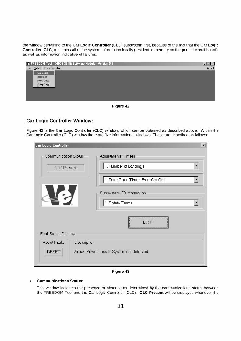
Car Logic Controller Window:
Figure 43 is the Car Logic Controller (CLC) window, which can be obtained as described above. Within the Car Logic Controller (CLC) window there are five informational windows: These are described as follows:
Figure 43
• Communications Status:
This window indicates the presence or absence as determined by the communications status between the FREEDOM Tool and the Car Logic Controller (CLC). CLC Present will be displayed whenever the

32
FREEDOM Tool and the Car Logic Controller (CLC) are communicating. In the event that communications cannot be established or is broken, the message displayed in the window will be CLC Absent .
• Landing: (Removed from USB Version)
This window indicates the landing at which the elevator is level with or the landing at which the elevator will be level with, if the elevator car is in motion.
• Adjustments/Timers:
This window displays two combo boxes which give the user the ability to select one of several adjustments or one of several timers associated with the Car Logic Controller (CLC). The upper combo box will drop down a partial listing of adjustments when the cursor is positioned within the combo box or positioned on the down arrow symbol and a single click of the pointing device is performed. The drop down options can be selected by utilizing the vertical scroll bar, typical of Windows programs, to reveal the full list of selections and clicking once with the pointing device button while the cursor positioned on the desired option. Refer to Figure 44.
Figure 44 The lower combo box will drop down a full listing of timers. Vertical scrolling is not required since all of the available selections are capable of being displayed in their entirety. A selection can be made by clicking once with the pointing device button while the cursor is positioned on the desired option. Refer to Figure 45.

33
Figure 45
• Subsystem I/O Information:
This window displays a combo box, which gives the user the ability to select one of several I/O ports in order to examine the port data contents associated with the Car Logic Controller (CLC). This combo box will drop down a partial listing of selections when the cursor is positioned within the combo box or positioned on the down arrow symbol and a single click of the pointing device is performed. The drop down options can be selected by utilizing the vertical scroll bar to reveal the full list of selections and clicking once with the pointing device button while the cursor positioned on the desired option. Refer to Figure 46.

34
Figure 46
• Fault Status Display:
This window displays the fault status associated with the Car Logic Controller (CLC) under the Description legend relative to the order in which faults are received at the FREEDOM Tool from the CLC module. There is a limit of twenty-five faults that can be displayed, due to the maximum size of the CLC’s fault history list resident at the CLC. The Description window will be updated approximately every 3.5 seconds and continually cycle through the recognized faults. Positioning the cursor over the RESET button under Reset Faults and clicking once with the pointing device will reset any repaired fault causing only the current faults to be displayed. In the event that no fault condition exists the Description window will display No Faults Detected .
As discussed, in the Adjustment/Timers and Subsystem I/O Information sections, the drop down options can be selected by utilizing the vertical scroll bar to reveal the full list of selections and clicking once with the pointing device button while the cursor is positioned on the desired menu option. A window associated with the option selected will be displayed with this window being consistent with all other Adjustment/Timers selections and Subsystem I/O selections. However, though consistency exists the Adjustment/Timers and Subsystem I/O Information are treated as different entities.
Adjustment / Timers Adjustment Window:
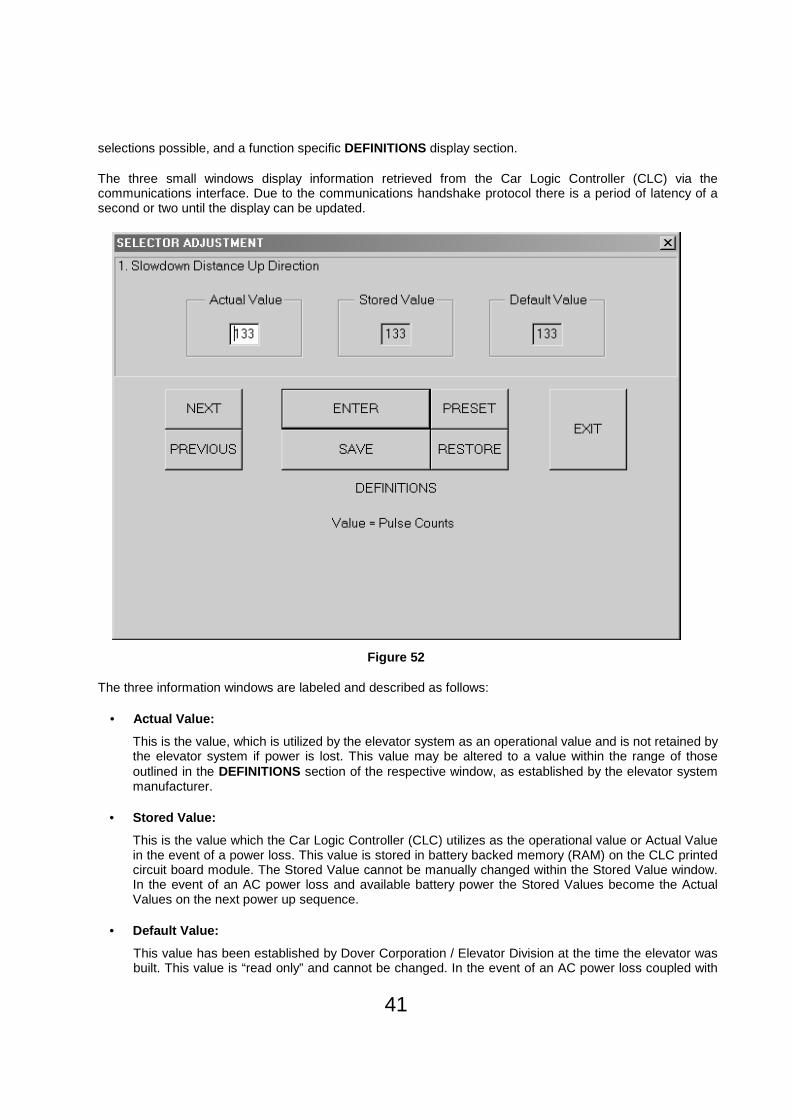
Referring to Adjustment/Timers and using the 1. Number of Landings selection as an example and referring to Figure 47 it is evident that there are three small windows that display information, seven function selections possible, and a function specific DEFINITIONS display section.

35
Figure 47 The three small windows display information retrieved from the Car Logic Controller (CLC) via the communications interface. Due to the communications handshake protocol there is a period of latency of a second or two until the display can be updated.
The three information windows are labeled and described as follows:
• Actual Value:
This is the value, which is utilized by the elevator system as an operational value and is not retained by the elevator system if power is lost. This value may be altered to a value within the range of those outlined in the DEFINITIONS section of the respective window, as established by the elevator system manufacturer.
• Stored Value:
This is the value which the Car Logic Controller (CLC) utilizes as the operational value or Actual Value in the event of a power loss. This value is stored in battery backed memory (RAM) on the CLC printed circuit board module. The Stored Value cannot be manually changed within the Stored Value window. In case of an AC power loss and available battery power, the Stored Values become the Actual Values on the next power up sequence.
• Default Value:
This value has been established by Dover Corporation / Elevator Division at the time the elevator was built. This value is “read only” and cannot be changed. In case of an AC power loss coupled with no battery power, the Default Values become the Stored and Actual Values on the next power up sequence.

36
The seven function selection buttons are labeled and described as follows:
• Enter:
The Actual Value can be edited by positioning the cursor within the Actual Value window and clicking once with the pointing device. Utilizing the PC keyboard numeric, backspace, and delete keys a different value can be entered into the window. In order to allow the elevator system to recognize the updated Actual Value , position the cursor over the ENTER button and click once with the pointing device.
• Save:
If it is desired that the Stored Value be updated, whereby the Stored Value is replaced with the Actual Value , position the cursor over the SAVE button and click once with the pointing device.
• Restore:
The function of the RESTORE button is to update the Actual Value with the Stored Value . Simply position the cursor over the RESTORE button and click once with the pointing device.
• Preset:
Positioning the cursor over the PRESET button and clicking once with the pointing device will cause the Actual Value to be replaced with the Default Value .
• Previous:
The PREVIOUS button is used to move backward (n-1, where n is the number associated with the present option viewed) to the previous option without going back to the original selection window. To execute the PREVIOUS function, position the cursor over the PREVIOUS button and click once with the pointing device.
• Next:
The NEXT button is used to move forward (n+1, where n is the number associated with the present option viewed) to the next option without going back to the original selection window. To execute the NEXT function, position the cursor over the NEXT button and click once with the pointing device.
• Exit:
The EXIT button will leave the active window and return to the window detailing the list of the option selections. To execute the EXIT function, position the cursor over the EXIT button and click once with the pointing device.
Subsystem I/O Information Display Window:
Subsystem I/O Information is displayed to the CRT much differently than the Adjustment/Timers. This stands to reason since the Adjustments/Timers data contains an Actual, Stored, and Default data for each specific parameter while the Subsystem I/O Information is a continuous snapshot of the specific selection. The Subsystem I/O Information is accessed in a manner identical to the Adjustment/Timers described above. Referring to Subsystem I/O Information and using the “1. Safety Terms” selection as an example and referring to Figure 48, there are three display information windows and three function buttons within the overall window.

37
Figure 48 The three Subsystem I/O Information windows are labeled and described as follows:
• I/O Information:
This window displays the individual bit patterns of the selection, in a bytewide (8 bits) format, for I/O information within the elevator control system. The horizontal scroll bar allows the user to walk through the individual bits and monitor the status of each of the eight bits as can be realized in the Signal and Condition windows.
• Condition:
The Condition window reveals an English translation and a description of the bit status of the signal being monitored via the I/O Information window as the user monitors a specific bit utilizing the horizontal scroll bar.
• Signal:
The Signal window displays an acronym or term known to those within the industry which describes the function of the specific bit being monitored. An “active low” logic signal is represented by an asterisk(*) appended to the Signal name within the Signal window.
The three function buttons are labeled and described as follows:
• Previous:
The PREVIOUS button is used to move backward (n-1, where n is the number associated with the present option viewed) to the previous option without going back to the original selection window. To execute the PREVIOUS function, position the cursor over the PREVIOUS button and click once with the pointing device.
• Next:
The NEXT button is used to move forward (n+1, where n is the number associated with the present option viewed) to the next option without going back to the original selection window. To execute the NEXT function, position the cursor over the NEXT button and click once with the pointing device.

38
• Exit:
The EXIT button will leave the active window and return to the window detailing the list of the option selections. To execute the EXIT function, position the cursor over the EXIT button and click once with the pointing device.
Once again, the Dover DMC-I Elevator System consists of up to four printed circuit board subsystems. These are as follows:
• Car Logic Controller (CLC) • Selector • Front Door • Rear Door
To select any one of the four subsystems position the cursor over the Select menu option within the Main window and single click the pointing device button. Moving the cursor over the desired subsystem and single clicking the pointing device will open that particular module window. The order in which the subsystems are selected is not important.
Selector Window:
Within the Selector window, shown in Figure 49, there are five informational windows: These are labeled and described as follows:
Figure 49

39
• Communications Status:
This window indicates the Selector printed circuit board presence or absence as determined by the ability of the FREEDOM Tool to recognize valid communications traffic between the Car Logic Controller (CLC) module and the Selector module. Selector Present will be displayed whenever the Selector and The Car Logic Controller (CLC) are communicating. In the event that communications cannot be established or is broken, the message displayed in the window will be Selector Absent .
• Landing: (Removed from USB Version)
This window indicates the landing at which the elevator is level with or the landing at which the elevator will be level with, if the elevator car is in motion.
• Adjustments:
This window displays a combo box, which gives the user the ability to select one of two
Figure 50
adjustments associated with the Selector. The combo box will drop down a partial listing of adjustments when the cursor is positioned within the combo box or positioned on the down arrow symbol and a single click of the pointing device is performed. The drop down options can be selected by clicking once with the pointing device button while the cursor is positioned on the desired option. Refer to Figure 50.
• Subsystem I/O Information:
This window displays a combo box, which gives the user the ability to select one of several I/O ports in order to examine the port data contents associated with the Selector. This combo box will drop down a list of options when the cursor is positioned within the combo box or positioned on the down arrow symbol and a single click of the pointing device is performed. The drop down options can be selected by

40
clicking once with the pointing device button while the cursor is positioned on the desired option. Refer to Figure 51.
Figure 51
• Fault Status Display:
This window displays the fault status associated with the Selector under the Description legend relative to the order in which faults are received at the FREEDOM Tool from the Selector module. A limit of three faults being displayed is due to the elevator system Selector fault allocation. The Description window will be updated approximately every 3 seconds and continually cycle through the recognized faults. Positioning the cursor over the RESET button under Reset Faults and clicking once with the pointing device will reset any repaired fault. In the event that no fault condition exists, the Description window will display No Faults Detected .
As discussed in the Adjustments and Subsystem I/O Information sections the drop down options can be selected by clicking once with the pointing device button while positioning the cursor on the desired menu option. A window associated with the option selected will be displayed with the data manipulation within the window being consistent with all other selections within the Adjustments and Subsystem I/O Information window. However, though consistency exists the Adjustments and Subsystem I/O Information are treated as different entities.
Selector Adjustment Window:
Referring to Adjustments and using the 1. Slowdown Distance Up Direction selection as an example and referring to Figure 52 it is evident that there are three small windows that display information, seven function
41
selections possible, and a function specific DEFINITIONS display section.
The three small windows display information retrieved from the Car Logic Controller (CLC) via the communications interface. Due to the communications handshake protocol there is a period of latency of a second or two until the display can be updated.
Figure 52
The three information windows are labeled and described as follows:
• Actual Value:
This is the value, which is utilized by the elevator system as an operational value and is not retained by the elevator system if power is lost. This value may be altered to a value within the range of those outlined in the DEFINITIONS section of the respective window, as established by the elevator system manufacturer.
• Stored Value:
This is the value which the Car Logic Controller (CLC) utilizes as the operational value or Actual Value in the event of a power loss. This value is stored in battery backed memory (RAM) on the CLC printed circuit board module. The Stored Value cannot be manually changed within the Stored Value window. In the event of an AC power loss and available battery power the Stored Values become the Actual Values on the next power up sequence.
• Default Value:
This value has been established by Dover Corporation / Elevator Division at the time the elevator was built. This value is “read only” and cannot be changed. In the event of an AC power loss coupled with

42
no battery power then the Default Values become the Stored and Actual Values on the next power up sequence.
The seven function selection buttons are labeled and described as follows:
• Enter:
The Actual Value can be edited by positioning the cursor within the Actual Value window and clicking once with the pointing device. Utilizing the PC keyboard numeric, backspace, and delete keys a different value can be entered into the window. In order to allow the elevator system to recognize of the updated Actual value position the cursor over the ENTER button and click once with the pointing device.
• Save:
If it is desired that the Stored Value be updated, whereby the Stored Value is replaced with the Actual Value , position the cursor over the SAVE button and click once with the pointing device.
• Restore:
The function of the RESTORE button is to update the Actual Value with the Stored Value. Simply position the cursor over the RESTORE button and click once with the pointing device.
• Preset:
Positioning the cursor over the PRESET button and clicking once with the pointing device will cause the Actual Value to be replaced with the Default Value.
• Previous:
The PREVIOUS button is used to move backward (n-1, where n is the number associated with the present option viewed) to the previous option without going back to the original selection window. To execute the PREVIOUS function, position the cursor over the PREVIOUS button and click once with the pointing device.
• Next:
The NEXT button is used to move forward (n+1, where n is the number associated with the present option viewed) to the next option without going back to the original selection window. To execute the NEXT function, position the cursor over the NEXT button and click once with the pointing device.
• Exit:
The EXIT button will leave the active window and return to the window detailing the list of the option selections. To execute the EXIT function, position the cursor over the EXIT button and click once with the pointing device.
Selector Subsystem I/O Information Display Window:
Subsystem I/O Information is displayed to the CRT much differently than the Adjustments. This stands to reason since the Adjustments data contains an Actual, Stored, and Default data for each specific parameter while the Subsystem I/O Information is a continuous snapshot of the specific option. The Subsystem I/O Information is accessed in a manner identical to the Adjustments described above. Referring to Subsystem I/O Information and using the 1. Port 1 selection as an example and referring to Figure 53. There are three display information windows and three function buttons within the overall window.

43
Figure 53
The three Subsystem I/O Information windows are labeled and described as follows:
• I/O Information:
This window displays the individual bit patterns of the selection, in a bytewide (8 bits) format, for I/O information within the elevator control system. The horizontal scroll bar allow the user to walk through the individual bits and monitor the status of each of the eight bits as can be realized in the Signal and Condition windows.
• Condition:
The Condition window reveals an English translation and a description of the bit status of the signal being monitored via the I/O Information window as the user monitors a specific bit utilizing the horizontal scroll bar.
• Signal:
The Signal window displays an acronym or term known to those within the industry which describes the function of the specific bit being monitored. An “active low” logic signal is represented by an asterisk(*) appended to the Signal name within the Signal window.
The three function buttons are labeled and described as follows:
• Previous:
The PREVIOUS button is used to move backward (n-1, where n is the number associated with the present option viewed) to the previous option without going back to the original selection window. To execute the PREVIOUS function, position the cursor over the PREVIOUS button and click once with the pointing device.
• Next:
The NEXT button is used to move forward (n+1, where n is the number associated with the present option viewed) to the next option without going back to the original selection window. To execute the NEXT function, position the cursor over the NEXT button and click once with the pointing device.

44
• Exit:
The EXIT button will leave the active window and return to the window detailing the list of the option selections. To execute the EXIT function, position the cursor over the EXIT button and click once with the pointing device.
The main Selector window also consists of two pushbuttons labeled Parameters and Hoistway Setup .
Hoistway Setup:
The Hoistway Setup procedure is described as follows:
1. The Hoistway Setup operation is initialized by positioning the cursor in the proximity of the Hoistway Setup button and clicking one time with the pointing device. This will open the Hoistway Setup window shown in Figure 54. This operation is generally executed due to one of the following: the time of installation of the elevator, when one of the hoistway magnets are relocated, when the terminal limit switches are moved, when power has been lost to the elevator system, or when replacing a CLC printed circuit board. In the event that the Selector module is deemed absent, an error message will occur within the window indicating such status.
Figure 54
If the Selector module is present and the user initiates a Hoistway Setup , the Hoistway Setup window will appear as in Figure 54 and prompt the user to comply with specific system requirements. The user is prompted to respond if all the information displayed in window is correct including the number of landings which is shown in a small window within the Hoistway Setup window. If the user concurs with the correctness of the information displayed within the window and desires to continue with the Hoistway Setup function, then the ENTER function must be enabled. This is done by

45
positioning the cursor on the ENTER button and clicking once with the pointing device. If it is not desirable to continue, but desirable to exit the Hoistway Setup then position the cursor on the EXIT button and click once with the pointing device.
2. A second Hoistway Setup window replaces the first Hoistway Setup window and prompts the user that the Selector Parameters and the Hoistway Parameter table will be cleared on enabling the ENTER function. Do this by positioning the cursor on the ENTER button and clicking once with the pointing device. If it is not desirable to continue, but desirable to exit the Hoistway Setup then position the cursor on the EXIT button and click once with the pointing device. Refer to Figure 55
Figure 55
3. A third Hoistway Setup window replaces the second Hoistway Setup window and prompts the user that the Selector Parameters have been reset, that the Selector is ready and to continue enable the ENTER function. This can be done by positioning the cursor on the ENTER button and clicking once with the pointing device. If it is not desirable to continue, but desirable to exit the Hoistway Setup then position the cursor on the EXIT button and click once with the pointing device. Refer to Figure 56.
It is important to realize that performing an EXIT function at this point will require that the user perform a Hoistway Setup prior to attempting to operate the elevator due to the Selector parameters having been reset.

46
Figure 56
4. A fourth Hoistway Setup window replaces the third Hoistway Setup window and prompts the user to run the car up on inspection, from the Bottom Directional Limit to the Top Directional Limit and to enable the ENTER function when finished. When the car has reached the top limit, position the cursor on the ENTER button and clicking once with the pointing device. If it is not desirable to continue, but desirable to exit the Hoistway Setup then position the cursor on the EXIT button and click once with the pointing device Refer to Figure 57.
The Hoistway Setup procedure should be repeated in the event that the car motion is interrupted prior to the car reaching the top limit.

47
Figure 57
5. A fifth Hoistway Setup window replaces the fourth Hoistway Setup window and prompts the user to save pulse counts on enabling the ENTER function. This is accomplished by positioning the cursor on the ENTER button and clicking once with the pointing device. If it is not desirable to continue, but desirable to exit the Hoistway Setup then position the cursor on the EXIT button and click once with the pointing device. Refer to Figure 58.

48
Figure 58
To summarize, the steps required to perform a Hoistway Setup are as follows:
1. Acknowledge the number of landings via the ENTER function.
2. Acknowledge the clearing of Selector parameters & the Hoistway Parameter Table via the ENTER function.
3. A second acknowledgment on the number of landings via the ENTER function is required to perform the actual Hoistway Setup operation.
4. After running the car on inspection from the Bottom Directional Limit to the Top Directional Limit select the ENTER function when finished.
5. An ENTER function is required to save the pulse counts, complete the Hoistway Setup operation, and return to the main Selector window.
Selector Parameters:
The Selector Parameters procedure is described as follows:
1. If the Selector module is present and the user positions the cursor on the Parameters pushbutton and clicks once with the pointing device the Selector Parameters window will be displayed as shown in Figure 59. The user is then prompted to enter the number of landings. This number is to be placed into the small window within the Selector Parameters window. This is done by single clicking on the window to the right of the initially displayed zero. To continue the user enters the number of landings and enables the ENTER function by positioning the cursor on the ENTER button and clicking once

49
with the pointing device. If it is not desirable to continue, but desirable to exit Parameters then position the cursor on the EXIT button and click once with the pointing device.
Figure 59
2. Continuing with Parameters causes a new message to appear within the Selector Parameters window, shown in Figure 60. The FREEDOM Tool is in the process of retrieving the Hoistway pulse counts from the Car Logic Controller (CLC). Once the FREEDOM Tool has received the pulse counts from the Car Logic Controller the window is updated with the pulse counts per each landing. The numbers that are displayed are the pulse counts that have been determined by a Hoistway Setup procedure. These are shown in Figure 61. To exit the Parameters window position the cursor on the EXIT button and click once with the pointing device. Single clicking on the ENTER button will perform a retrieval of the Hoistway pulse counts from the Car Logic Controller (CLC) as previously stated.

50
Figure 60

51
Figure 61
Once again the Dover DMC-I Elevator System consists of up to four printed circuit board subsystems. These are as follows:
• Car Logic Controller (CLC) • Selector • Front Door • Rear Door
Important: All information concerning the Front Doo r is valid for the Rear Door as well.
To select any one of the four DMC-I subsystems, position the cursor over the Select menu option within the Main window and single click the pointing device button. Moving the cursor over the desired software module and single clicking the pointing device will open that particular subsystem window. The order in which the modules are selected is not important.
Front and Rear Door Windows:
Within the Door window, Front or Rear, shown in Figure 62, there are five informational windows: These are labeled and described as follows:

52
Figure 62
• Communications Status:
This window indicates the presence or absence as determined by the ability of the FREEDOM Tool to recognize valid communications traffic between the Car Logic Controller (CLC) module and the Door module(s). Door Present will be displayed whenever the Door and the Car Logic Controller (CLC) are communicating. In the event that communications cannot be established or is broken the message displayed in the window will be Front Door Absent or Rear Door Absent , where appropriate.
• Landing: (Removed from USB Version)
This window indicates the landing at which the elevator is level with or the landing at which the elevator will be level with, if the elevator car is in motion.
• Adjustments:
This window displays a combo box which gives the user the ability to select one of several adjustments associated with the Door. The combo box will drop down a partial listing of adjustments when the cursor is positioned within the combo box or positioned on the down arrow symbol and a single click of the pointing device is performed. The drop down options can be selected by clicking once with the pointing device button while the cursor is positioned on the desired option. Refer to Figure 63.

53
Figure 63
• Subsystem I/O Information:
This window displays a combo box, which gives the user the ability to select one of several I/O ports in order to examine the port data contents associated with the Door. This combo box will drop down a list of options when the cursor is positioned within the combo box or positioned on the down arrow symbol and a single click of the pointing device is performed. The drop down options can be selected by clicking once with the pointing device button while the cursor is positioned on the desired option. Refer to Figure 64.

54
Figure 64
• Fault Status Display:
This window displays the fault status associated with the particular Door module under consideration below the Description legend relative to the order in which faults are received at the FREEDOM Tool from the Door module. A limit of three faults being displayed is due to the elevator system door fault allocation. The Description window will be updated approximately every 3.5 seconds and continually cycle through the recognized faults. Positioning the cursor over the RESET button under Reset Faults and clicking once with the pointing device will reset any repaired fault. In the event that no fault condition exists, the Description window will display No Faults Detected .
As discussed in the Adjustments and Subsystem I/O Information sections the drop down menu options can be selected by clicking once with the pointing device button while positioning cursor on the desired option. A window associated with the option selected will be displayed with the data manipulation within the window being consistent with all other selections within the Adjustments and Subsystem I/O Information window. However, though consistency exists the Adjustments and Subsystem I/O Information are treated as different entities.
Door Adjustment Window:
Referring to Adjustments and using the 1. Door Open High Speed selection as an example and referring to Figure 65 it is evident that there are three small windows that display information, seven function selections possible, and a function specific “DEFINITIONS” display section.
The three small windows display information retrieved from the Car Logic Controller (CLC) via the communications interface. Due to the communications handshake protocol there is a period of latency of a

55
second or two until the display can be updated.
Figure 65
The three information windows are labeled and described as follows:
• Actual Value:
This is the value, which is utilized by the elevator system as an operational value and is not retained by the elevator system if power is lost. This value may be altered to a value within the range of those outlined in the DEFINITIONS section of the respective window, as established by the elevator system manufacturer.
• Stored Value:
This is the value which the Car Logic Controller (CLC) utilizes as the operational value or Actual Value in the event of a power loss. This value is stored in battery backed memory (RAM) on the CLC printed circuit board module. The Stored Value cannot be manually changed within the Stored Value window. In the event of an AC power loss and available battery power the Stored Values become the Actual Values on the next power up sequence.
• Default Value:
This value has been established by Dover Corporation / Elevator Division at the time the elevator was built. This value is “read only” and cannot be changed. In the event of an AC power loss coupled with no battery power then the Default Values become the Stored and Actual Values on the next power up sequence.

56
The seven function selection buttons are labeled and described as follows:
• Enter:
The Actual Value can be edited by positioning the cursor within the Actual Value window and clicking once with the pointing device. Utilizing the PC keyboard numeric, backspace, and delete keys a different value can be entered into the window. In order to allow the elevator system to recognize the updated Actual value position the cursor over the ENTER button and click once with the pointing device.
• Save:
If it is desired that the Stored Value be updated, whereby the Stored Value is replaced with the Actual Value , position the cursor over the SAVE button and click once with the pointing device.
• Restore:
The function of the RESTORE button is to update the Actual Value with the Stored Value. Simply position the cursor over the RESTORE button and click once with the pointing device.
• Preset:
Positioning the cursor over the PRESET button and clicking once with the pointing device will cause the Actual Value to be replaced with the Default Value.
• Previous:
The PREVIOUS button is used to move backward (n-1, where n is the number associated with the present option viewed) to the previous option without going back to the original selection window. To execute the PREVIOUS function, position the cursor over the PREVIOUS button and click once with the pointing device.
• Next:
The NEXT button is used to move forward (n+1, where n is the number associated with the present option viewed) to the next option without going back to the original selection window. To execute the NEXT function, position the cursor over the NEXT button and click once with the pointing device.
• Exit:
The EXIT button will leave the active window and return to the window detailing the list of the option selections. To execute the EXIT function, position the cursor over the EXIT button and click once with the pointing device.
Door Subsystem I/O Information Display Window:
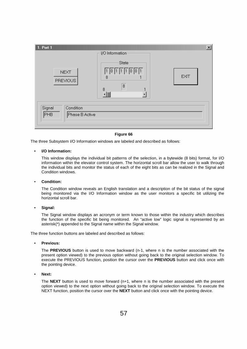
Subsystem I/O Information is displayed to the CRT much differently than the Adjustments. This stands to reason since the Adjustments data contains an Actual, Stored, and Default data for each specific parameter while the Subsystem I/O Information is a continuous snapshot of the specific selection. The Subsystem I/O Information is accessed in a manner identical to the Adjustments described above. Referring to Subsystem I/O Information and using the 1. Port 1 selection as an example and referring to Figure 66. There are three display information windows and three function buttons within the overall window.
57
Figure 66
The three Subsystem I/O Information windows are labeled and described as follows:
• I/O Information:
This window displays the individual bit patterns of the selection, in a bytewide (8 bits) format, for I/O information within the elevator control system. The horizontal scroll bar allow the user to walk through the individual bits and monitor the status of each of the eight bits as can be realized in the Signal and Condition windows.
• Condition:
The Condition window reveals an English translation and a description of the bit status of the signal being monitored via the I/O Information window as the user monitors a specific bit utilizing the horizontal scroll bar.
• Signal:
The Signal window displays an acronym or term known to those within the industry which describes the function of the specific bit being monitored. An “active low” logic signal is represented by an asterisk(*) appended to the Signal name within the Signal window.
The three function buttons are labeled and described as follows:
• Previous:
The PREVIOUS button is used to move backward (n-1, where n is the number associated with the present option viewed) to the previous option without going back to the original selection window. To execute the PREVIOUS function, position the cursor over the PREVIOUS button and click once with the pointing device.
• Next:
The NEXT button is used to move forward (n+1, where n is the number associated with the present option viewed) to the next option without going back to the original selection window. To execute the NEXT function, position the cursor over the NEXT button and click once with the pointing device.
58
• Exit:
The EXIT button will leave the active window and return to the window detailing the list of the option selections. To execute the EXIT function, position the cursor over the EXIT button and click once with the pointing device.
The main Door window also consists of two radio buttons labeled Parameters and Startup Sequence .
Door Startup Sequence:
The Door Startup Sequence procedure is described as follows:
Prior to executing the Door Startup Sequence procedure, the following conditions must be met:
1. A Hoistway Setup operation must have been executed. 2. The car must be placed on inspection. 3. The car must be near any floor level. 4. The Door printed circuit board module must be reset or the AC power recycled. The reset will clear
any faults from the Door operator.
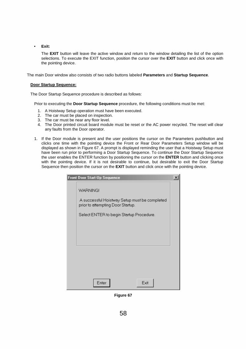
1. If the Door module is present and the user positions the cursor on the Parameters pushbutton and clicks one time with the pointing device the Front or Rear Door Parameters Setup window will be displayed as shown in Figure 67. A prompt is displayed reminding the user that a Hoistway Setup must have been run prior to performing a Door Startup Sequence. To continue the Door Startup Sequence the user enables the ENTER function by positioning the cursor on the ENTER button and clicking once with the pointing device. If it is not desirable to continue, but desirable to exit the Door Startup Sequence then position the cursor on the EXIT button and click once with the pointing device.
Figure 67

59
2. A second Door Startup window replaces the first Door Startup window and prompts the user that the Door Parameters will be cleared on enabling the ENTER function. This is done by positioning the cursor on the ENTER button and clicking once with the pointing device. If it is not desirable to continue, but desirable to exit the Door Startup Sequence then position the cursor on the EXIT button and click once with the pointing device. Refer to Figure 68.
Figure 68
3. A third Door Startup window replaces the second Door Startup window and prompts the user that the Door Parameters have been reset, that the Door is ready, the inspection switch must be placed on AUTO, the doors themselves should begin to cycle, and if no faults exist enable the ENTER function by positioning the cursor on the ENTER button and clicking once with the pointing device. If it is not desirable to continue, but desirable to exit the Door Startup then position the cursor on the EXIT button and click once with the pointing device. Refer to Figure 69.

60
Figure 69
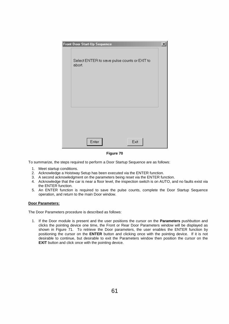
4. A fourth Door Startup window replaces the third Door Startup window and prompts the user that to save pulse counts on enabling the ENTER function by positioning the cursor on the ENTER button and clicking once with the pointing device. If it is not desirable to continue, but desirable to exit the Door Startup then position the cursor on the EXIT button and click once with the pointing device. Refer to Figure 70.
61
Figure 70
To summarize, the steps required to perform a Door Startup Sequence are as follows:
1. Meet startup conditions. 2. Acknowledge a Hoistway Setup has been executed via the ENTER function. 3. A second acknowledgment on the parameters being reset via the ENTER function. 4. Acknowledge that the car is near a floor level, the inspection switch is on AUTO, and no faults exist via
the ENTER function. 5. An ENTER function is required to save the pulse counts, complete the Door Startup Sequence
operation, and return to the main Door window.
Door Parameters:
The Door Parameters procedure is described as follows:
1. If the Door module is present and the user positions the cursor on the Parameters pushbutton and clicks the pointing device one time, the Front or Rear Door Parameters window will be displayed as shown in Figure 71. To retrieve the Door parameters, the user enables the ENTER function by positioning the cursor on the ENTER button and clicking once with the pointing device. If it is not desirable to continue, but desirable to exit the Parameters window then position the cursor on the EXIT button and click once with the pointing device.

62
Figure 71
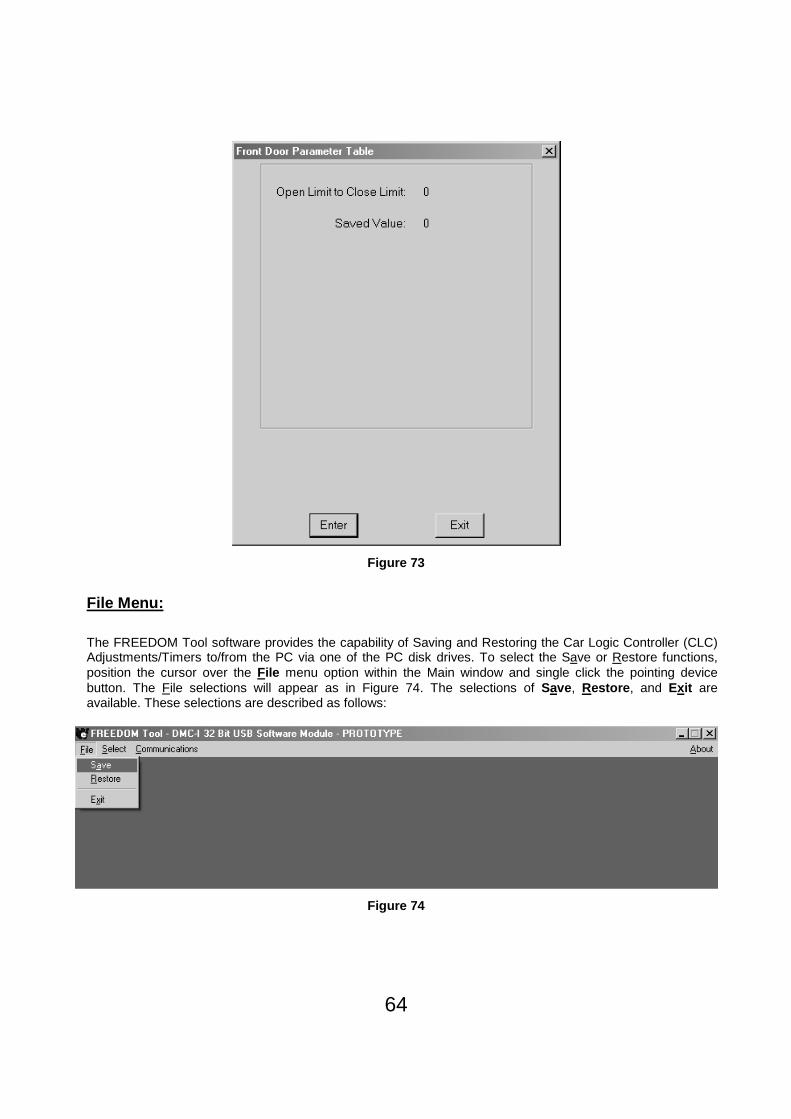
2. Continuing with Parameters causes a new message to appear within the Front or Rear Door Parameters window, shown in Figure 72. The FREEDOM Tool is in the process of retrieving the Door count limit from the Car Logic Controller (CLC). Once the FREEDOM Tool has received the count limit from the Car Logic Controller, the window is updated with this count limit. The numbers that are displayed are the count limits that have been determined by a Door Startup Sequence procedure as shown in Figure 73. To exit the Parameters window position the cursor on the EXIT button and click once with the pointing device. Single clicking on the ENTER button will perform a retrieval of the count limits from the Car Logic Controller (CLC) as previously stated.

63
Figure 72
64
Figure 73
File Menu:
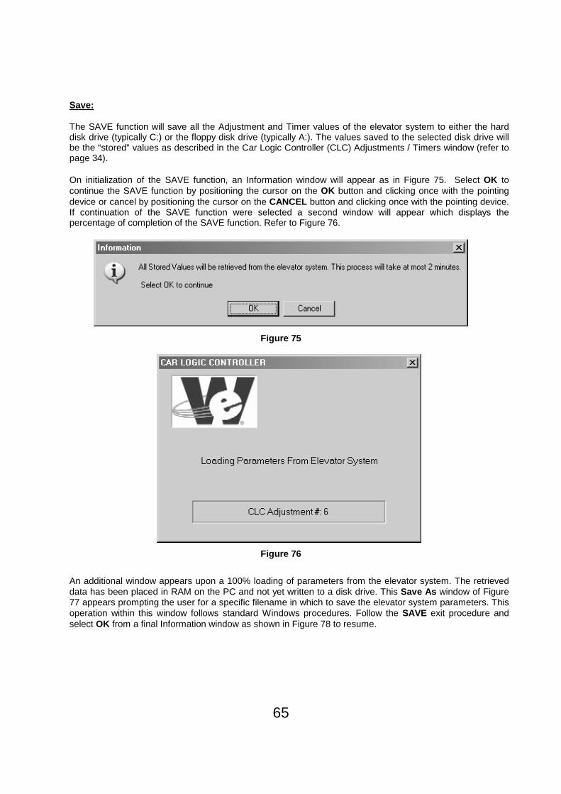
The FREEDOM Tool software provides the capability of Saving and Restoring the Car Logic Controller (CLC) Adjustments/Timers to/from the PC via one of the PC disk drives. To select the Save or Restore functions, position the cursor over the File menu option within the Main window and single click the pointing device button. The File selections will appear as in Figure 74. The selections of Save, Restore , and Exit are available. These selections are described as follows:
Figure 74
65
Save:
The SAVE function will save all the Adjustment and Timer values of the elevator system to either the hard disk drive (typically C:) or the floppy disk drive (typically A:). The values saved to the selected disk drive will be the “stored” values as described in the Car Logic Controller (CLC) Adjustments / Timers window (refer to page 34).
On initialization of the SAVE function, an Information window will appear as in Figure 75. Select OK to continue the SAVE function by positioning the cursor on the OK button and clicking once with the pointing device or cancel by positioning the cursor on the CANCEL button and clicking once with the pointing device. If continuation of the SAVE function were selected a second window will appear which displays the percentage of completion of the SAVE function. Refer to Figure 76.
Figure 75
Figure 76
An additional window appears upon a 100% loading of parameters from the elevator system. The retrieved data has been placed in RAM on the PC and not yet written to a disk drive. This Save As window of Figure 77 appears prompting the user for a specific filename in which to save the elevator system parameters. This operation within this window follows standard Windows procedures. Follow the SAVE exit procedure and select OK from a final Information window as shown in Figure 78 to resume.

66
Figure 77
Figure 78
Restore
The RESTORE function will download (PC to CLC) the Saved information (Adjustment and Timers of the elevator system) described above from either the hard disk drive (typically C:) or the floppy disk drive (typically A:). These restored values will become both the “Actual” and the “Stored” values within the Car Logic Controller (CLC) Adjustments / Timers Window (refer to page 34). A Windows Open dialog box will appear, the operation within the window being consistent with standard Windows procedures. Refer to Figure 79. Select OK to continue the RESTORE function. An Information window will appear as in Figure 80. Select OK to continue the RESTORE function by positioning the cursor on the OK button and clicking once with the pointing device or cancel by positioning the cursor on the CANCEL button and clicking once with the pointing device. Selecting OK brings up an additional window which indicates the percentage of completion of the parameters written to the elevator system, refer to Figure 81. Follow the RESTORE exit procedure and select OK from a final Information window as shown in Figure 82 to resume.

67
Figure 79
Figure 80

68
Figure 81
Figure 82
Exit
The Exit function will cause the FREEDOM Tool application specific program (DMC-I Version 675A or DMC-I Version 675D) to close and return to the FREEDOM Tool Shell program. Disconnect the “Dover DMC Interface” box prior to performing this EXIT function.
DMC File Utility
The DMC File Utility (data examination tool) included with the FREEDOM Tool is a convenient way to view the values saved at the job site when not at the job site. This utility allows the user to view the “edf ” or elevator data files that the user saved using the Save command in the FREEDOM Tool. See Page 65 for more information.
Start Up :
The start up procedure for the DMC File Utility is described as follows:
1. Open the window titled Applications. Inside this window are two icons, one the FREEDOM Tool, the other the DMC File Utility.
2. With the Applications window open select the DMC File Utility Icon by positioning the cursor over the Icon with the pointing device and double clicking the pointing device button.

69
3. When done successfully the screen will appear as shown in Figure 83.
Figure 83
General Description:
To view an edf file, the user, must know the filename of the file desired. In the DMC File Utility main window the user is informed that there is No File Loaded , as seen in the Status window. The user is given 5 choices for performing a function and 5 choices for viewing parts of any given file. These are described as follows:
Load File
This option allows the user to select the specific file to be retrieved for viewing. Selecting Load File will open a standard Windows Open dialog window, see Figure 84, in which the user can select the drive, folder, and filename they desire to open.

70
Figure 84
Print File
This option allows the user to print out the data file giving the user a hard copy of the saved elevator parameters. To use this option the user would press the Print File push button on the main window. This option will only work if you have a printer connected and the computer is set up to use that particular printer on the printer port.
Save File
The DMC File Utility allows the user to make changes to any adjustment saved by the FREEDOM Tool. These changes are done through the different adjustment viewing sections of the DMC File Utility. When a file has been changed the tool informs the user as to the changed status through the Status Window as seen in Figure 85. If the file has changed, the status window will state 2 things. First, it will have the text description, Current File Changed , at the top of the window. Second, it will show the name of the current file selected. To save the current file the user must select the button labeled, Save File . Selecting Save File will open a standard windows Save As dialog box where the user can choose the location to save the file, and type in the name of the updated file. When the file is successfully saved, the Status Window will update showing Current File Saved and the filename. Refer to Figure 86.

71
Figure 85
Figure 86
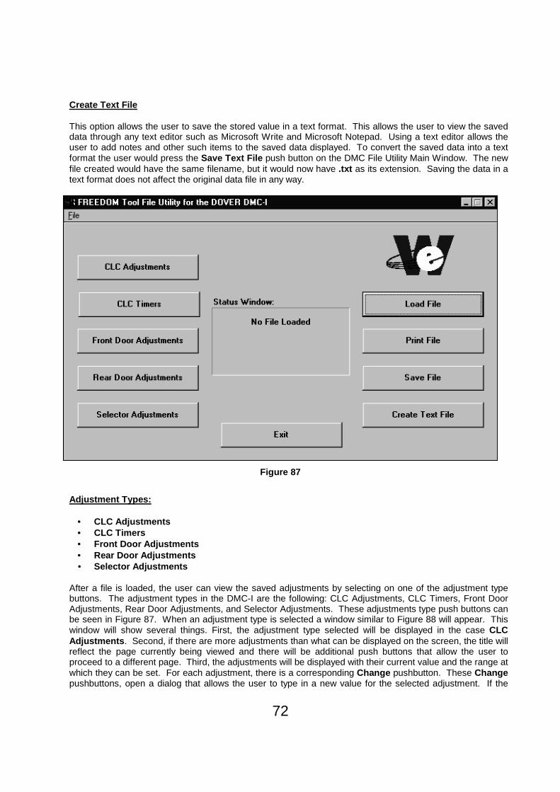
72
Create Text File
This option allows the user to save the stored value in a text format. This allows the user to view the saved data through any text editor such as Microsoft Write and Microsoft Notepad. Using a text editor allows the user to add notes and other such items to the saved data displayed. To convert the saved data into a text format the user would press the Save Text File push button on the DMC File Utility Main Window. The new file created would have the same filename, but it would now have .txt as its extension. Saving the data in a text format does not affect the original data file in any way.
Figure 87
Adjustment Types:
• CLC Adjustments • CLC Timers • Front Door Adjustments • Rear Door Adjustments • Selector Adjustments
After a file is loaded, the user can view the saved adjustments by selecting on one of the adjustment type buttons. The adjustment types in the DMC-I are the following: CLC Adjustments, CLC Timers, Front Door Adjustments, Rear Door Adjustments, and Selector Adjustments. These adjustments type push buttons can be seen in Figure 87. When an adjustment type is selected a window similar to Figure 88 will appear. This window will show several things. First, the adjustment type selected will be displayed in the case CLC Adjustments . Second, if there are more adjustments than what can be displayed on the screen, the title will reflect the page currently being viewed and there will be additional push buttons that allow the user to proceed to a different page. Third, the adjustments will be displayed with their current value and the range at which they can be set. For each adjustment, there is a corresponding Change pushbutton. These Change pushbuttons, open a dialog that allows the user to type in a new value for the selected adjustment. If the

73
value entered is within the range for the selected adjustment, the adjustment display window will be updated showing the new value. Also, the status window section of the main window will update showing File Changed .
Figure 88
Exit
This option allows the user to leave the DMC File Utility. The user needs to press the button labeled Exit within the DMC File Utility main window to enable this option.

74
SUBSYSTEM I/O Bit Definitions:
CLC
1. Safety Terms:
b1 - CST, Car Stop Switch b2 - HW, Hoistway Door Contacts b3 - DR, Door Gate Switch b4 - IN, Inspection / Automatic b5 - WD24 - 24V DC Supply Watch Dog b6 - N/A b7 to b8 - N/A
2. Registered Car Calls:
b1 - 8C, 8th Floor Car Call b2 - 7C, 7th Floor Car Call b3 - 6C, 6th Floor Car Call b4 - 5C, 5th Floor Car Call b5 - 4C, 4th Floor Car Call b6 - 3C, 3rd Floor Car Call b7 - 2C, 2nd Floor Car Call b8 - 1C, 1st Floor Car Call
3. Input Port 0 (LCC 1):
b1 - SP13, Car Call Lockout 3 b2 - CIS, Car In Service b3 - DCB, Door Close Button b4 - DOB, Door Open Button b5 - CST, Car Stop Switch b6 - HWP, 24V Presence b7 - WD24, Watch Dog b8 - IN, Inspection / Automatic
4. Input Port 1:
b1 - MSEL, Emergency Power Manual Selection Switch b2 - FCC, Fireman’s Car Cancel b3 - CFS2, Car Fireman’s Service Phase 2 b4 - CFS1, Car Fireman’s Service Phase 1 b5 - 4C, 4th Floor Car Call b6 - 3C, 3rd Floor Car Call b7 - 2C, 2nd Floor Car Call b8 - 1C, 1st Floor Car Call
5. Input Port 2:
b1 - EPW, Emergency Power Transfer Warning b2 - NP, Normal Power b3 - 4D, 4th Floor Down Directional Hall Call b4 - 3U, 3rd Floor Up Directional Hall Call b5 - 3D, 3rd Floor Down Directional Hall Call b6 - 2U, 2nd Floor Up Directional Hall Call b7 - 2D, 2nd Floor Down Directional Hall Call b8 - 1U, 1st Floor Up Directional Hall Call

75
6. Input Port 3:
b1 - OTS2, High Temperature Contact b2 - OTS1,Low Temperature Contact b3 - FSX, Fire Service Alternate b4 - FSM, Fire Service Main b5 - SPI2, Car Call Lockout 2 b6 - SPI1, Car Call Lockout 1 b7 - HFS2, Hall Fireman’s Service Phase 2 b8 - HFS1, Hall Fireman’s Service Phase 1
7. Input Port 4:
b1 - SPI7, Car Call Lockout 7 b2 - SPI6, Car Call Lockout 6 b3 - SPI5, Car Call Lockout 5 b4 - SPI4, Car Call Lockout 4 b5 - 8C, 8th Floor Car Call b6 - 7C, 7th Floor Car Call b7 - 6C, 6th Floor Car Call b8 - 5C, 5th Floor Car Call
8. Input Port 5:
b1 - 8D, 8th Floor Down Directional Hall Call b2 - 7U, 7th Floor Up Directional Hall Call b3 - 7D, 7th Floor Down Directional Hall Call b4 - 6U, 6th Floor Up Directional Hall Call b5 - 6D, 6th Floor Down Directional Hall Call b6 - 5U, 5th Floor Up Directional Hall Call b7 - 5D, 5th Floor Down Directional Hall Call b8 - 4U, 4th Floor Up Directional Hall Call
9. Output Port 0:
b1 - ISI, Independent Service b2 - DHL, Down Hall Lantern b3 - UHL, Up Hall Lantern b4 - UMD, Up Main Drive b5 - RDM, Run Down Mode b6 - RUM, Run Up Mode b7 - LE, Leveling b8 - RHS, Run High Speed
10. Output Port 1:
b1 - I4, 4th Floor Position Indicator b2 - I3, 3rd Floor Position Indicator b3 - I2, 2nd Floor Position Indicator b4 - I1, 1st Floor Position Indicator b5 - 4C, 4th Floor Registered Car Call b6 - 3C, 3rd Floor Registered Car Call b7 - 2C, 2nd Floor Registered Car Call b8 - 1C, 1st Floor Registered Car Call

76
11. Output Port 2:
b1 - SPO1, Car Call Lockout 1 b2 - FHS, Hall Fire Service b3 - b8, N/A
12. Output Port 3:
b1 - DDA, Down Directional Arrow b2 - UDA, Up Directional Arrow b3 - FSI, Fire Service independent b4 - VMR, Viscosity Motor Run b5 - SPO2, Car Stop Switch Override b6 - BUZ, Fireman Service Buzzer b7 - CSTO, b8 - RET, Fireman Service Return
13. Output Port 4:
b1 - I8, 8th Floor Position indicator b2 - I7, 7th Floor Position indicator b3 - I6, 6th Floor Position indicator b4 - I5, 5th Floor Position indicator b5 - 8C, 8th Floor Registered Car Call b6 - 7C, 7th Floor Registered Car Call b7 - 6C, 6th Floor Registered Car Call b8 - 5C, 5th Floor Registered Car Call
14. Output Port 5:
b1 - 8D, 8th Floor Down Directional Hall Call b2 - 7U, 7th Floor Up Directional Hall Call b3 - 7D, 7th Floor Down Directional Hall Call b4 - 6U, 6th Floor Up Directional Hall Call b5 - 6D, 6th Floor Down Directional Hall Call b6 - 5U, 5th Floor Up Directional Hall Call b7 - 5D, 5th Floor Down Directional Hall Call b8 - 4U, 4th Floor Up Directional Hall Call
15. CLC Serial Outputs to Front Door Operator:
b1 - OD, Open Door b2 - CD, Close Door b3 - LIMRE, Command to Use Door Open Limit b4 - NUDG, Nudging Operation Command b5 - CDA, Close Door Assist Command b6 - LOCK, Lock Door Command b7 - SETUP, Door Parameters Found b8 - CLRFL, Clear fault Flag

77
16. Front Door Serial Inputs to CLC:
b1 - DOLX, Door Open Limit Switch b2 - DCL, Door Close Limit b3 - DR, Door Gate Contact b4 - FAULT, Door Has No New Faults b5 - N/A b6 - READY, Door Ready / Not Ready b7 - SE, Safety Edge b8 - EE, Electric Eye
17. CLC Outputs to Selector:
b1 - GU, Running Up b2 - GD, Running down b3 - N/A b4 - N/A b5 - SYNC, Pulse Counts Agree with Magnets b6 - SETUP, Selector parameters Found b7 - CLRFL, Clear Faults b8 - IN, Inspection / Automatic
18. Selector Serial Inputs to CLC, Set 1:
b1 - FAULT, No New Faults b2 - LCR, Late Car Refusal Point b3 - Level, Car Is Level b4 - READY, Selector Is Ready b5 - TARGE, Binary Count A for Target Floor b6 - TARGE, Binary Count B for Target Floor b7 - TARGE, Binary Count C for Target Floor b8 - TARGE, Binary Count D for Target Floor
19. Selector Serial Inputs to CLC, Set 2:
b1 - SLIMIT, TDL or BDL b2 - FATL, Fatal Errors b3 - RUN, Run Signal b4 - FAST, Fast Solenoid b5 - UP, Up Motion b6 - UPS, Up Solenoid b7 - DN, Down Motion b8 - DNS, Down Solenoid
20. Selector Serial Inputs to CLC, Set 3:
b1 - J3X, Jumper J3 A b2 - J3X, Jumper J3 B b3 - J3X, Jumper J3 C b4 - J3X, Jumper J3 D b5 - LU, Level Up b6 - LD, Level Down b7 - DZD, Door Zone Down b8 - DZU, Door Zone Up

78
21. Port 1(Hardware Port on Micro):
b1 - PHB, Phase B Sensor b2 - DZR, Door Zone Relay b3 - SI, Slow Down interrupt b4 - DTS, Down Slowdown b5 - UTS, Up Slowdown b6 - TSL, Top Speed Limit b7 - TDL, Top Directional Limit b8 - BDL, Bottom Directional Limit
22. Hall Fire Service No. 1:
b1 - AHFS, Hall fire Service Signal to Car b2 - CPDF, Car Presence at Desired Floor b3 - HFS1, Hall Fire Switch Phase 1 b4 - HFS2, Hall Fire Switch Phase 2 b5 - FSX, Other Fire Sensors b6 - FSM, fire Sensor Main Floor b7 - SINH, Start Inhibit b8 - EEINH, Electric Eye Inhibit
23. Hall fire Service No. 2:
b1 - AHFS, Hall fire Service Signal to Car b2 - RET, Fire Service Return b3 - NB, Nudging Buzzer b4 - FSI, Fire Service Indicator b5 - CSTO, Car Stop Switch Override b6 - FIROV, Hall Fire Service Bypass b7 - FIRTO, Door To Go Off Fire T.O. B8 - FIRDT, Delay before independent Service
24. Car fire Service No. 1:
b1 - ACFS, Fire Service b2 - CPDF, Car Floor Presence b3 - CFS1, Car Fireman’s Service Switch 1 b4 - CFS2, Car Fireman’s Service Switch 2 b5 - DCPB, Door Close Push-button b6 - DOPB, Door Open Push-button b7 - RDCPB, Rear Door Close Push-button b8 - RDOP, Rear Door Open Push-button
25. Car fire Service No. 2:
b1 - ACFS, Fire Service b2 - OD, Front Door Open b3 - CD, Front Door Close b4 - DOL, Front Door Open Limit b5 - ROD, Rear Door Open b6 - RCD, Rear Door Close b7 - RDOL, Rear Door Open Limit b8 - FSRCL, Fire Service Recall

79
26. Viscosity Control:
b1 - COVO, Car Viscosity Operation b2 - CPVF, Car Presence Viscosity Floor b3 - OTS1, Oil Low Temperature b4 - OTS2, Oil High Temperature b5 - VMR, Viscosity Motor Signal b6 - ONLIN, Car On Line b7 - LEVEL, Car Level b8 - DLEVE, Dead Level
27. Emergency Power:
b1 - NP, Normal Power b2 - EPW, Emergency Power Warning b3 - N/A b4 - UMD, Up Motion Detected b5 - LEVEL, Car Level b6 - AHFS, Hall fire Service b7 - CPDF, Car Presence at Desired Floor b8 - CCALL, Cancel Car Calls
28. Power Unit I/O:
b1 - RUM, Run up Micro b2 - RDM, Run Down Micro b3 - RHS, Run High Speed b4 - UMD, Up Motion Detected b5 - LE, Leveling b6 - IN, Inspection / Automatic b7 - HW, Hoistway Door Contacts b8 - DR, Door Gate Switch
29. Car Homing:
b1 - N/A b2 - N/A b3 - N/A b4 - N/A b5 - N/A b6 - CCINH, Car call Inhibit b7 - N/A b8 - N/A
30. Preference:
b1 - UPREF, Up Preference b2 - DPREF, Down Preference b3 - N/A b4 - N/A b5 - N/A b6 - N/A b7 - N/A b8 - N/A
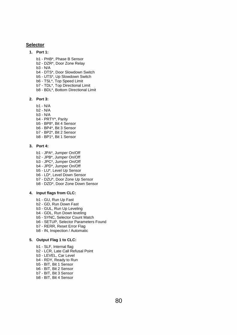
80
Selector
1. Port 1:
b1 - PHB*, Phase B Sensor b2 - DZR*, Door Zone Relay b3 - N/A b4 - DTS*, Door Slowdown Switch b5 - UTS*, Up Slowdown Switch b6 - TSL*, Top Speed Limit b7 - TDL*, Top Directional Limit b8 - BDL*, Bottom Directional Limit
2. Port 3:
b1 - N/A b2 - N/A b3 - N/A b4 - PRTY*, Parity b5 - BP8*, Bit 4 Sensor b6 - BP4*, Bit 3 Sensor b7 - BP2*, Bit 2 Sensor b8 - BP1*, Bit 1 Sensor
3. Port 4:
b1 - JPA*, Jumper On/Off b2 - JPB*, Jumper On/Off b3 - JPC*, Jumper On/Off b4 - JPD*, Jumper On/Off b5 - LU*, Level Up Sensor b6 - LD*, Level Down Sensor b7 - DZU*, Door Zone Up Sensor b8 - DZD*, Door Zone Down Sensor
4. Input flags from CLC:
b1 - GU, Run Up Fast b2 - GD, Run Down Fast b3 - GUL, Run Up Leveling b4 - GDL, Run Down leveling b5 - SYNC, Selector Count Match b6 - SETUP, Selector Parameters Found b7 - RERR, Reset Error Flag b8 - IN, Inspection / Automatic
5. Output Flag 1 to CLC:
b1 - SLF, Internal flag b2 - LCR, Late Call Refusal Point b3 - LEVEL, Car Level b4 - RDY, Ready to Run b5 - BIT, Bit 1 Sensor b6 - BIT, Bit 2 Sensor b7 - BIT, Bit 3 Sensor b8 - BIT, Bit 4 Sensor

81
6. Output Flag 2 to CLC:
b1 - SLMT, TDL or BDL b2 - LOCK, System Stable b3 - RUN, Run Car b4 - FAST, Fast Solenoid b5 - UP, Up Motion b6 - US, Up Solenoid b7 - DN, Down Motion b8 - DS, Down Solenoid
FRONT and REAR Door
1. Port 1:
b1 - CTC*, Center Of Travel b2 - MDC, Manual Door Close Input b3 - MDO, Manual Door Open Input b4 - ADWR, Address Write Line b5 - ADRD, Address Read Line b6 - ADINT, Address Interrupt Line b7 - N/A b8 - PHB, Phase B Sensor
2. Port 3:
b1 - J4, Address Jumper J4 b2 - J3, Address Jumper J3 b3 - J2, Address Jumper J2 b4 - J1, Address Jumper J1 b5 - N/A b6 - DIR, Door Closing b7 - PC, Pulser Command b8 - PC, Pulser Command
3. Door Close Limit:
b1 - N/A b2 - N/A b3 - N/A b4 - N/A b5 - N/A b6 - N/A b7 - N/A b8 - DCL, Door Close Limit
4. Door Open limit:
b1 - N/A b2 - N/A b3 - N/A b4 - N/A b5 - N/A b6 - N/A b7 - N/A b8 - DOL, Door Open Limit

82
5. Adjusted Door Open Limit:
b1 - N/A b2 - N/A b3 - N/A b4 - N/A b5 - N/A b6 - N/A b7 - N/A b8 - DOLX, Door Open Limit
6. Open Door:
b1 - N/A b2 - N/A b3 - N/A b4 - N/A b5 - N/A b6 - N/A b7 - N/A b8 - OD, Open Door
7. Close Door:
b1 - N/A b2 - N/A b3 - N/A b4 - N/A b5 - N/A b6 - N/A b7 - N/A b8 - CD, Close Door
8. Input Flags 1 From CLC:
b1 - OD, Open Door b2 - CD, Close Door b3 - LREV, Limited Door Reopen b4 - NUDG, Nudge b5 - CDA, Close Door Assist Command b6 - LOCK, Door Lock b7 - SETUP, Door Parameters Found b8 - RERR, Clear Faults
9. Input Flags 2 From CLC:
b1 - N/A b2 - N/A b3 - N/A b4 - N/A b5 - N/A b6 - EEI*, Electric Eye Inhibit b7 - ISE, Ignore Safety Edge b8 - ISR, Inhibit Safety Edge Full Return

83
10. Internal Door flags:
b1 - FLT, Faults b2 - INST, Setup Mode b3 - INSF, Safety Edge b4 - NOHS, High Speed Operation b5 - DST, Destination is Door Closed Limit b6 - RDY, Doors Ready b7 - N/A b8 - INC, Increment Duty Cycle
11. Pulser Port:
b1 - DOL*, Door Open Limit b2 - DCL*, Door Close Limit b3 - DR, Door Gate Switch b4 - WD, 150V Watch Dog b5 - OC9, OC9 Status b6 - OC8, OC8 Status b7 - SE, Safety Edge b8 - EE, Electric Eye

84
DMC-I Adjustment/Timer Worksheet
Sample For Your Records
CLC Adjustment 6 stop duplex Site #1 Site #2 Site #3
* 1. Number of Landings 6
2. Primary Floor 2
3. Primary Fire Return Floor 2
4. Alternate Fire Return Floor 1
5. Hall Lanterns / Car Lanterns 0
6. Low Oil Return Floor 2
7. Hospital Fire Service Override 1
8. Emergency Return Floor 1
9. Emergency Power Type 1
10. Lower Parking 1
11. Car Call Lockout Override 0
*12. Selective Door Flag 0
13. Limited Door Reopen 0
14. Fire Service Door Operation 3
15. ADA Service 0
16. Canadian B44 Code 0
17. Anti-Nuisance 0
18. Landing Passing Tone Enabled 1
19. Fire Service Code 1
20. Nudging Operation 0
21. I/O Expansion Board 1
* 22. Master/Slave 2
* 23. Number of Cars in a Group 2
24. Fire Service - CA / 1989 ANSI 0
25. Medical Operation - MA 0
26. Parking Floor 2
27. Car Call Disable A 1
28. Car Call Disable B 0
29. Car Call Disable C 0
30. Car Call Disable D 0
31. Car Call Disable E 0
32. Stop Car Switch / Door Hold Switch 0
33. Stop Switch Level Up Option 1
34. First Car to Auto Lower 1
35. Second Car to Auto Lower 2
36. Third Car to Auto Lower 1
37. Car Call Disable F 0

85
38. Close Landing 0
39. Car Call Tone Enable (Canada) 0
*40. Validate Front Doors 1-4 For Group 15
*41. Validate Front Doors 5-7 For Group 3
*42. Validate Rear Doors 1-4 For Group 0
*43. Validate Rear Doors 5-7 For Group 0
*44. Validate Front Doors 1-4 For Car 15
*45. Validate Front Doors 5-7 For Car 3
*46. Validate Rear Doors 1-4 For Car 0
*47. Validate Rear Doors 5-7 For Car 0
48. Group Parking 0
49. Telescoping Jack Function 0
50. Force Re-Sync 0
51. Front Code Blue Calls 1-4 0
52. Front Code Blue Calls 5-7 0
53. Rear Code Blue Calls 1-4 0
54. Rear Code Blue Calls 5-7 0
55. Enable Code Blue Calls 0
56. Fire Service (Great Britain) 0
57. 1st Landing Digital P.I. 0
58. 2nd Landing Digital P.I. 0
59. 3rd Landing Digital P.I. 0
60. 4th Landing Digital P.I. 0
61. 5th Landing Digital P.I. 0
62. 6th Landing Digital P.I. 0
63. 7th Landing Digital P.I. 0
64. 8th Landing Digital P.I. 0
65. Predictive Maintenance 0
66. Floor Height 1-2 0
67. Floor Height 2-3 0
68. Security Door Open Button Operation 0
69. Fire Service Door Type 0
70. Emergency Power Door Type 0
71. Low Oil Door Type 0
72. Door Disconnect 0
73. Register Car Calls 0
74. Cycle Car Calls 0
* Must be entered prior to performing a Hoistway Setup.
Important note : The range of values that can be entered is dependent upon the version of software installed
as indicated on the CLC EPROM’s.

86
Sample For Your Records CLC Timers
6 stop duplex
Site #1
Site #2
Site #3
1. Door Open Time - Front Car Call 5
2. Door Open Time - Electric Eye 6
3. Door Open Time - Door Open Button 5
4. Door Open Time – Front Hall Call 5
5. Nudging Time 30
6. Door Open Time – ADA Hall Call 45
7. Door Open Time –Stuck Button 60
8. PI Timeout 2
9. Door Open Time -Rear Car Call 5
10. Door Open Time - Rear Hall Call 5
11. Low Oil Timer 100
12. Limited Door Reopen Time 3
13. Door Open Time – Code Blue 45
14. Stuck Door Sensor Device Timer 38
15. Door Fail Time 17
16. Emergency Power Failure Time 120
17. Delay Start Timer 0
18. Parking Wait Timer 10
19. Initial Jack Re-Synchronization Timer 14
20. Main Jack Re-Synchronization Timer 1
21. Jack Re-Synchronization Time 15 `
22. Twin-Jack Sensor Timer 30
Sample For Your Records Selector Adjustments
6 stop duplex
Site #1
Site #2
Site #3
1. Slowdown Distance in Up Direction
85
2. Slowdown Distance in Down Direction
46

87
Sample For Your Records Front Door Adjustments
6 stop duplex
Site #1
Site #2
Site #3
1. Door Open High Speed
98
2. Door Open Deceleration
16
3. Door Open - Manual Operation
50
4. Door Open Acceleration
6
5. Door Open Slowdown Distance
200
6. Door Open Final Slowdown Distance
12
7. Door Close High Speed
50
8. Door Close Deceleration
16
9. Door Close - Manual Operation
25
10. Door Close Acceleration
4
11. Door Close Slowdown Distance
110
12. Door Close Final Slowdown Distance
34
13. Initial / Final Door Close Force
40
14. Mid-Travel Door Close Force
60
15. Nudging Speed
20
16. Door Test Mode
0
17. Manual Speed Mode
0
18. Open Backlash Speed
20
19. Backlash
5