this document has been reproduced from microfiche. … · 2013-08-30 · technical report data...
TRANSCRIPT
N O T I C E
THIS DOCUMENT HAS BEEN REPRODUCED FROM MICROFICHE. ALTHOUGH IT IS RECOGNIZED THAT
CERTAIN PORTIONS ARE ILLEGIBLE, IT IS BEING RELEASED IN THE INTEREST OF MAKING AVAILABLE AS MUCH
INFORMATION AS POSSIBLE
https://ntrs.nasa.gov/search.jsp?R=19990008477 2020-02-18T15:17:08+00:00Z

E A/6BB/R-98/129September 1998
III M 111111111111111111PB99-104697
Evaluation of Convergent Spray Technology" Spray Process forRoof Coating Application
by
J. Scarpa, B. Creighton, T. Hall, IC 1 iamlin, T. Ho-tvard, M. Kelly,Q. Lundy, and L. Thomson
Materials & Processes DepartmentUnited Space Boosters, Inc.Huntsville, Alabama 35895
Environmental Technology InitiativeProject No. 427IAG with NASA
Project Officer
Pain M. RandallSustainable Technology Division
National Risk Management Research LaboratoryCincinnati, Ohio 45268
NATIONAL RISK MANAGEMENT RESEARCH LABORATORYOFFICE OF RESEARCH AND DEVELOPMENT
U.S. EtN'% ITRONMENTAL PROTECTION AGENCYCINCINNATI, OHIO 45268
1tev11ooueco er:
Na11aW r i ^nre ma^lo6Pk67M1-, Wak" 22141
P

TECHNICAL REPORT DATA(Pease read Instructions on the reverse befort completin '
(III^^ ^^
1. REPORT NO. 2. 3. F II^I'^^1I' ^'I"II InEPA/600/R-98/124 PB99 -1046 97
4. TITLE AND SUBTIT' E. RErvn I UATESeptember 1998
EVALUA7 ION OF CONVERGENT SPRAY TECHNOLOGY"" 6. PERFORMING ORGANIZATION CODE
SPRAY PROCESS FOR COATING APPLICATION7. AUTHOR(S) B. PERFORMING ORGANIZATION REPORT NO.
J. Scarpa, B. Creighton, T. Hall, K. Hamlin, T. Howard, M. Kelly,Q. Lundy, and L. Thomson
0. PERFORMING ORGANIZATION NAME AND ADDRESS 10. PROGRAM ELEMENT NO.
United Space Boosters, Inc. 11. CONTRA T GRANT NOEnvironmental Technology Initiative,188 Sparkman Drive
Huntsville, Alabama 35805 Project No. 427, IAG with NASA12. SPONSORING AGENCY NAME AND ADDRESS 13. TYPE OF REPORT AND PERIOD COVERED.National Risk Management Research Laboratory
14, SPONSORING AGENCY CODEOffice of Research and DevelopmentU.S. Environmental Protection AgencyCincinnati Ohin 45768
EPA/600/14
16. SUPPLEMENTARY NOTES
Project Officer: Paul M. Randall (513) 569-767316. ABSTRACT
The overall goal of this project was to demonstrate the feasibility of Convergent Spray Technology'"'' forthe roofing industry. This was accomplished by producing an environmentally compliant coating utilizingrecyci- a materials, a CST' spray process portable application cart, and a hand-held applicator with aCST' spray process nozzle. The project culminated with' application of this coating to a nine hundredsixty square foot metal for NASA Marshall Space Flight Center (MSFC) in Huntsville, Alabama.
The project was executed in three phases. Phase one involved Independent Research and Development(IRAD) experimentation with materials, formulations, and CST' spray process. In phase two,. thecoatings were tested and the spray process was refined. Coatings were applied in two field demonstrationsas part of the third phase. Funding for phases two and three was provided by Environmental TechnologyInitiative (ETI).
7. KEY WORDS AND DOCUMENT ANALYSIS
a. DESCRIPTORS b.IDENTIFIERS/OPEN ENDED TERMS c. COSATI Field(Group
Coatings Pollution PreventionSpray Technology Waste MinimizationRoof Coating Solvent AlternativesRoofing MaterialArchitectural Coating
16. DISTRIBUTION STATEMENT 19. SECURITY CLASS (This Report/ 21. NO. 38 PAGES
UnclassifiedRelease to Public 20. SECURIT' CLASS (This page)
Unclassified22. PRICE
EPA Form 2220-1 (Rev. 4-77) PREVIOUS EDITION IS OBSOLETE

NOTICE
The U.S. Environmental Protection Agency through its Office of Researchand Development funded the research described here under EnvironmentalTechnology Initiative Project No. 427 IAG to NASA under subcontract toUnited Space Boosters, Inc. It has been subjected to the Agency's peer andadministrative review and has been approved for publication as an EPAdocument. Mention of trade names or commercial products does notconstitute endorsement or recommendation for use.
PFORE'W'ORD
The U.S. Environmental Protection Agency is charged by Congress withprotecting the Nation's land, air, and water resources. Under a mandateof national environmental laws, the Agency strives to formulate andimplement actions leading to a compatible balance between humanactivities and the ability of natural systems to support and nurture life. Tomeet this mandate, EPA's research program is providing data and technicalsupport for solving environmental problems today and building a scienceknowledge base necessary to manage our ecological resources wisely,understand. how pollutants affect our health, and prevent or reduceenvironmental risks in the future.
The National Risk Management Research Laboratory is the Agency'scenter for investigation of technological and management approaches forreducing risks from threats to human health and the environment. Thefocus of the Laboratory's research program is on methods for theprevention and control of pollution to air, land, water and subsurfaceresources; protection of water quality in public water systems; remediationof contaminated sites and ground water; and prevention and control ofindoor air pollution. The goal of this research effort is to catalyzedev- pment and implementation of innovative, cost-effectiveenvironmental technologies; develop scientific and engineering informationneeded b;, EPA to support regulatory and policy decisions; and providetechnical support and information transfer to ensure effectiveimplementation of environmental regulations and strategies.
The overall goal of this project was to demcnstrate the feasibility ofConvergent Spray TechnologyT"' for the roofing industry. This wasaccomplished by producing an environmentaily compliant coating utilizingrecycled materials, a CS7` spray process portable application cart, and ahand-held applicator with a C^TTM spray process nozzle. The projectculminated with application of this coating to a nin° hundred sixty squarefoot metal for NASA Marshall Space flight. Center (MSFC) in Huntsville,Alabama.
The project was executed in three phases. Phase one involved IndependentResearch and Development (IRAD) experimentation with materials,formulations, and CSVm spray process. rn phase two, the coatings weretested and the spray process was refined. Coatings were applied in twofield demonstrations as part of the third phase. Funding for phases twoand three was provided by Environmental Technology Initiative (ETI).
E. Timothy Oppelt, DirectorNational Risk Management Research Laboratory

P
ABSTRACT
A survey of the roofing industry was performed to determine how CST'"spray process might best serve the market (LJT-31-95MP).Environmentally compliant, low-volatile organic content (VOC) roofpaints, coatings, and recycled fillers were investigated. Samples of thesematerials were evaluated, individually and in various combinations, bothfor processability and material characteristics. Hand mixes, sprays, andcursory materials testing aided the down-select process.
From these experiments, two final formulations were selected. Twowaterborne paints were selected as candidate vehicles for the filler. Thefiller material selected was ground, treated recycled tire rubber, with orwithout twenty percent by volume polyester flock (a gar g ent industrybyproduct). Later testing indicated the superior elongation of the purerubber-filled coating verses the rubber/flock-filled, therefore the finalproduct was ten percent by Aveight pure ground rubber. A portable CSTIm
spray process cart was designed and constructed, along with a hand-heldCST spray wand. These efforts completed phase one.
Refinement of the spray process involved testing the t,vo selected basecoatings with a select ratio of filler to establish op .-imum sprayedcharacteristics for the paint systems. The neat paints, established industrycoatings, served as the baseline to compare with she candidateformulations. Test sprays led to the establishment of spray parametersspecific to these materials. Test data is contained in Appendix I.
In August 1996, a demonstration coating was applied to a portion ofNASA MSFC Building 4675 roof on Redstone Arsenal. The coating wassprayed over both the galvanized steel aluminum painted substrate andover a foam insulation surface on the same roof. As performance of thiscoating was monitored, material tests continued.
In April 1997, a coating was applied to the west section roof of NASAMSFC Building 4734 on Redstone Arsenal. Photographs of these roofs andthe spray process are located in Appendix 11. Real time Nvear, performance,and weatherability of these coatings wi ll be monitored on a limited basis.
IV

P
CONTENTS
Foreword...............................................iiiAbstract............................................... ivList of Tables ........................................... viApplicable Documentation ................................ viiList of Symbols, Abbreviations, and Acronyms ................. viiiAcknowledgements ....................................... ix
1.0 INTRODUCTION ................................. 11 .1 Scope ....................................... 11.2 Background .................................. 11.3 CST Background .............................. 2
2.0 MATERIAL SELECTION ............................ 32.1 Coating Selection .............................. 32.2 Filler Selection ................................ 3
3.0 TEST SPRAYS .................................... 5
4.0 TESTING ........................................ 64.1 Moisture Resistance ............................ 64.2 Adhesion .................................... 64.3 Tensile and Elongation .......................... 74.4 Flexibility Tests / Substrate Adhesion ............... 74.5 Water Vapor Permeance ........................ 74.6 Weatherability ................................ 8
5.0 ROOF DEMONSTRATION SPRAYS .................. 95.1 Small Scale Roof Demonstration Spray ............. 95.2 Large Scale Roof Demonstration Spray ............. 9
6.0 SUMMARY AND CONCLUSIONS .................. 10
APPENDIX .......................................... 12APPENDIX II .......................................... 20
V

LIST OF TABLES (Appendix I)
Table 1 Water Immersion. Test
Table 2 abstrate Adhesion by Tape Test
Table 3 Tensile Strength and Elongation
Table 4 Flexibility of Attached Coatings
Cost Savings Calculation
Vi
P
LIST OF PHOTOS (Appendix H)
Photo 1 Building 4675-CST" Roof Coating Over Foam ..... 21
Photo 2 Building 4675-CST" Roof Coating Over Metal andFoam...................................... 21
Photo 3 Building 4734-Before Cleaning and Preparation ofRoof....................................... 22
Photo 4 Building 4734-Before Cleaning and Preparation ofRoof ........................ .............. 22
Photo 5 Building 4734-Pressure Washing Operation ........ 23
Photo 6 Building 4734-Mastic Application for Penetrations ... 23
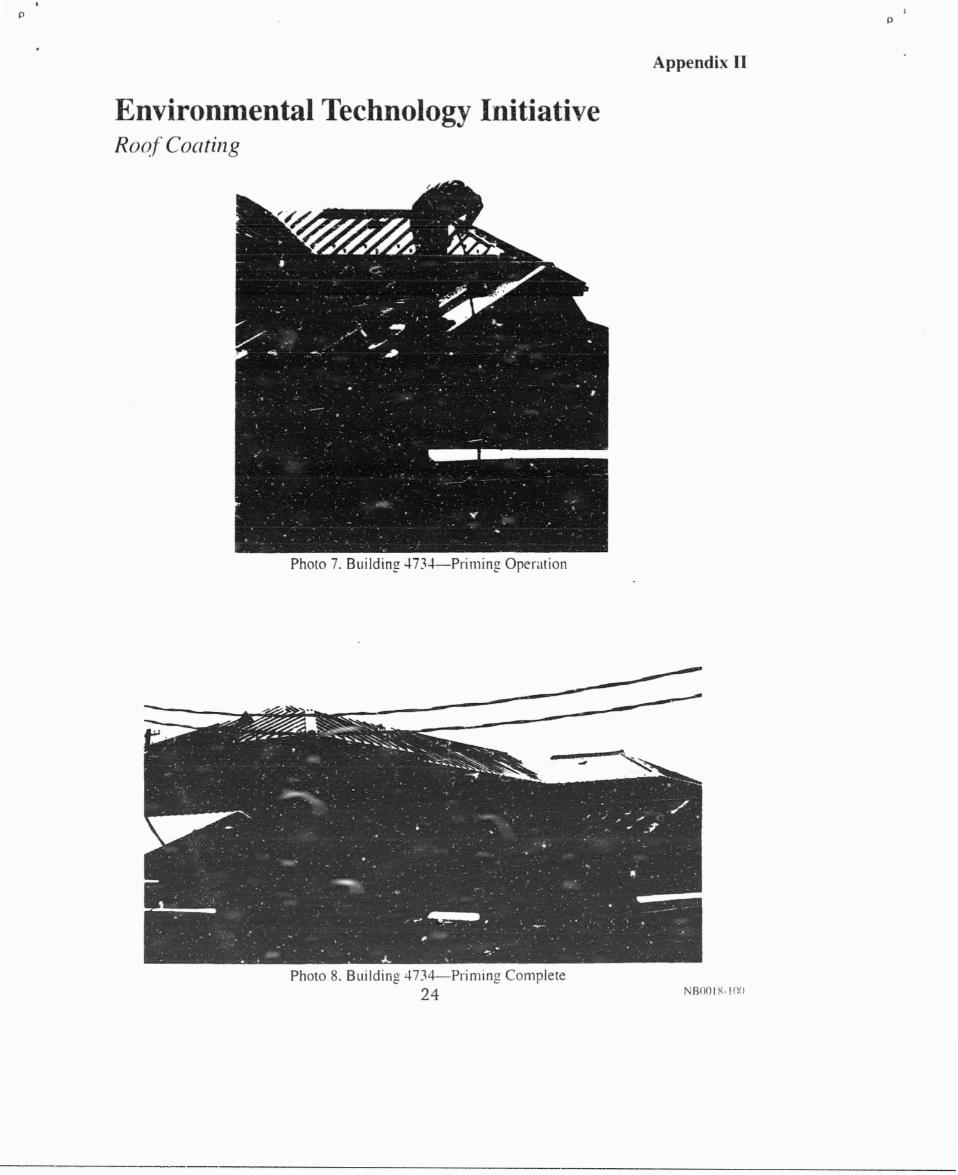
Photo 7 Building 4734-Priming Operation ................ 24
Photo 3 Building 4734-Priming Complete ................ 24
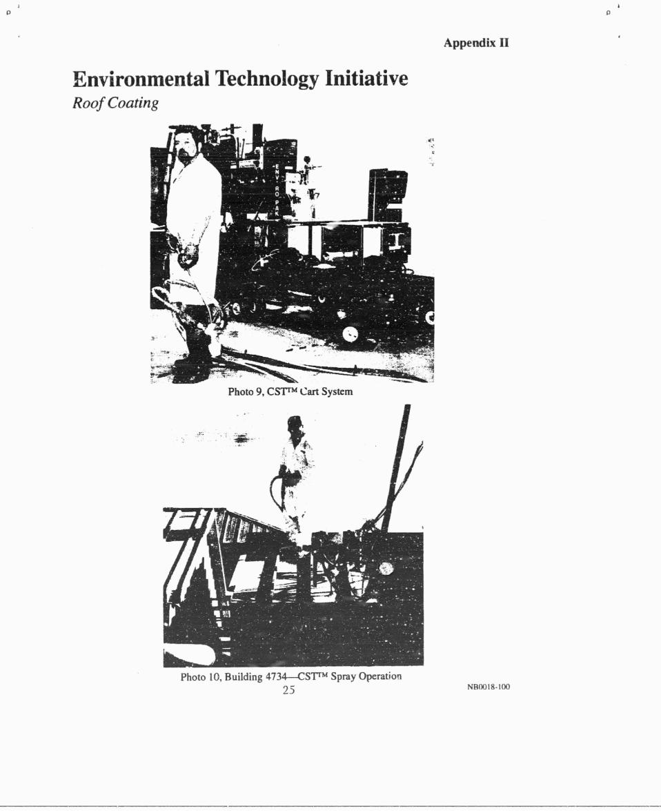
Photo 9 Building CST"' Cart wstem .................... 25
Photo 10 Building 4734-CST" Spray Operation ............ 25
Photo 11 Building 4734-CST" Spray Operation ............ 26
Photo 12 Building 4734-CST" Test Patch without TopcoatSouth Side Arith 2 Panels Left Uncoated ........... 26
Photo 13 Building 4734-North Side Arith White TopcoatApplied .................................... 27
vn

P
APPLICABLE DOCUMENTATION
ASTM D 522 Standard Test Method of Attached Organic Coatings
ASTM D 714 Standard Test Method for Evaluatinx . Degree ofBlistering of Paints
ASTM D 870 Standard Practice for Testing Water Resistance ofCoatings Using Water Immersion
ASTM D 2370 Standard Test Method foi Tensile Properties ofOrganic Coatings
ASTM D 3359 Standard Test Methods for Measuring Adhesion byTape Test
ASTM G 53 Standard Practice for Operating Light- and Water-Exposure Apparatus (Fluorescent UV-CondensationType) for Exposu-° of Nonmetallic Materials
viii
LIST OF SYMBOLS, ABBREVIATIONS, AND ACRONYMS
CST Convergent Spray TechnologyLPA Environmental Protection AgencyETI Energy Technology InitiativeF FahrenheitIRAD Independent Research and Development (IR&D)MSFC Marshall Space Flight CenterSRB Solid Rocket BoostersUV UltravioletVOC Volatile Organic Compo:ind
Ix

ACKNOWLEDGEMENTS
Research, development, testing, and application of this roof coating wasaccomplished from the combined coi,tributions of many people. Sincerethanks and appreciation go out to the following for assistance with thiseffort.
United Technologies
USBI Technology Development Group including:
Bill CreightonTerry HallKvle HamlinTony HowardMatt KellyQuentin LundyJack ScarpaLarry Thomson
NASA
MSFC John WestVernotto McMillianCarl Lester
x

t..11Vt.11Y1Y11/1, V111V Z_/GVV
tEPRODUM w:U.S. Dyraent of ce..o w "M
kWWAd Teelekm Wan1YSe iavke{achy Y , Vh5b" Intl
EXECUTIVE SUMMARY
A survey of the rooEng industry was performed to determine how CST'spray process might best serve the market (LJ T-31-95MP).Environmentally compliant, low-volatile organic content (VOC) roofpaints, coatings, and recycled fillers were investigated. Samples of thesemateriels were evaluated, individually and in various combinations, bothfor processability and material characteristics. Hand mixes, sprays, andcursory materials testing aided the down-select process.
From these experimeii s, two final formulations were selected. Twowaterborne paints were selected as candidate vehicles for the filler. Thefiller material selected was ground, treated recycled tire rubber, with orwithout twenty percent by volume polyester flock (a garment industryi)yproduct). Later testing indicated the superior elongation of the purerubber-filled coating verses the ribber/flock-filled, therefore the finalproduct was ten percent by weigh'_ pure ground rubber. A portable CSTrmspray process cart vas designed and constructed, along with a hand-heldCST spray wand. These efforts completed phase one.
Refinement of the spray process involved testing the two selected basecoatings with a select ratio of fille: to establish optimum sprayedcharacteristics for the paint systems. Ti- - neat paints, established industrycoatings, served as the baseline to compare with the candidateformulations. Test sprays led to the establishment of spray parametersspecific to these materials. Test data is contained in Appendix I.
In August 1996, a demonstration coating was applied to a portion ofNASA MSFC Building 4675 roof on Redstone Arsenal. The coating wassprayed over both the galvanized steel aluminum painted substrate andover a foam insulation surface on the same roof. As performance of thiscoating was monitored, material tests continued.
In April 1997, a coating was applied to the west section roof of NASAMSFC Building 4734 on Redstone Arsenal. Photographs of these roofsand the spray process are located in Appendix 11. Real time wear,performance, and weatherability of these coatings will be monitored on alimited basis.
P
X1


Release to Public
EPA Fens 2220-1 (Rev. 4-7}) PREvIOUS KO1TION IS OBSOLETE
1.0 INTRODUCTION
1.1 Scope
Task Directive 83, Commercialization of Solventless Spray Technology forRoof Applications, is an Energy Technology Initiative (ETI) effort todemonstrate the feasibilty of using the Convergent Spray Technology TM
spray process in the commercial arena. The goal was to produce anenvironmentally compliant coating and a portable spray technology forapplication of materials to environmentally-friendly "green buildings".To remain within the Enviroit,nental Protection Agency's (EPA) directivefor an environmentally acceptable product, this study focuses on non-bituminous, environmentally compliant materials. While low-VOCcoatings are already available in the roofing industry, results from theTask Directive 83 study serve to further reduce VOC emissions and toincorporate the use of recycled materials through the use of CST TM sprayprocess.
1.2 Background
In response to environmental legislation, the roofing industry developedreduced Volatile Organic Compound (VOC) protective coatings for metaland foam roofs. In an effort to further reduce these emission levels,CSTT1! may be employed to incorporate recycled fillers into the coatingsystem. The addition of fillers serves to decrease the total amount ofcoating required for a given area, thereby decreasing emissions.
For Task Directive 83, an environmentally compliant coating system wasproduced using an existing waterborne low-VOC acrylic coating filled withrecycled materials - materials which would otherwise be scrapped to a landfill. This coating system was developed to be applied via a CST TM sprayprocess portable cart system with a hand-held spray applicator.
Materials evaluation and formulations were accomplished under USBIIndependent Research and Development (IRAD), as was the constructionof the portable cart and spray applicator. Process refinement, test sprays,material testing, and roof spray demonstrations were performed under thetask directive.

P
1.3 CST Background
The CSTTM spray process was originally developed to robotically applyhighly filled thermal protection coatings to the Space Shuttle Solid RocketBoosters (SRB) without aid of the solvents normally required for thesehighly loaded systems. With this technology, high filler concentrationsare added to a two-part resin as it exits an air assisted nozzle. Becausethese pneumatically delivered fillers are added exterior to the nozzle,solvents are not required to reduce the viscosity of the resin/fillermixture. CST technology was also selected by the Air Force to applythermal protection to the Titan N payload fairing.
For Task Directive 83, this process was adapted to a portable spray cart witha specially designed spray wand suitable for the commercial roofingindustry. This system is especially suited to coat "green buildings". Theunique design will accept one- or two-part resin systems and a variety offiller materials.
2
P
2.0 MATERIAL SELECTION (Internal IRAD)
2.1 Coating Selection
During the IRAD phase of this project, three commercially availableacrylic roof paints were selected to test as base paints for a CSTTM sprayprocess candidate coating. Two of these coatings were waterborne vinylacrylics, one was a waterborne elastomeric. Acrylic was chosen for itsdurability, economy, ease of use, ultraviolet (UV) resistance, andenvironmental compliance. Waterborne systems were selected for easy,non-hazardous use and clean-up, as well as their low VOC content. Oneconsideration in selecting the elastomer based material was its ability towithstand contraction and expansion of a metal roof without cracking.
2.2 Filler Selection
A variety of fillers were considered for the acrylic coating system.Materials examined included polyester fabric flock, choppedpolypropylene, chopped polyester, rayon flock, nylon flock, choppedrecycled tire rubber, polyester monofilament fibers, woolsastonite/silane,mica, and aluminum fibers. The majority of these materials were eitherrecycled or industry by-product materials. Laboratory hand-mixes weremade with the fillers and small scale testing of strength, flexibility, andmoisture absorption narrowed down the selection. Following are briefcomments on some of these fillers.
Polyester flock, a by-product of the garment industry, was easily wetted bytwo of the paints and proved strong and moisture resistant. The difficultywith this material for CST was in delivering (feeding) the materialconsistently to the spray applicator, due to its tendency to clump.
Chopped polypropylene did not mix as easily with the tested paintsystems. Rayon also appeared to have potential wetting problems. Bothmaterials produced relatively strong coatings, but like the polyester flock,were difficult to feed evenly. Tests showed flock did feed well whenmixed with recycled rubber.
Polyester monofilament produced a strong candidate material when hand-mixed. However, monofilaments could not be consistently delivered,through the variety of feeders and end effectors which were tested.
3
Experimental sprays with mica proved this material too lightweight forsatisfactory convergent mixing. Though aluminum fibers producedstrong reflective coatings, they were expensive and inflexible.
Recycled tire rubber (with and without polyester flock mixed in) fedthrough the hopper and end effector easily and mixed well with thewaterborne coatings, producing a strong elastic coating. A variety of grades(sizes) of ground rubber were tested, both surface-treated and untreated.Surface treated rubber was found to produce a stronger material than anyof the untreated rubber material tested. Various fill levels were examinedand tested, ultimately resulting in selection of a system with ten percent byweight ground rubber and ninety percent by weight waterborne acrylicelastomeric paint.
4
E. Timothy Oppelt., DirectorNational Risk Management Research Laboratory
3.0 TEST SPRAYS
From the selection process summarized in Section 2, several series of testsprays were performed with various concentrations of filler ranging fromthree to forty percent. Results from preliminary sprays helped establish afiller upper level concentration of twenty percent. Both pure rubber and arubber/polyester flock mixture were sprayed for material tests, in an effortto optimize the final coating system.
Panels were prepared for moisture resistance, tensile strength, elongation,weatherometer aging, and mandrel bend flexibility tests. As part of anIRAD effort, experiments were run with two feed systems and several endeffectors. These experiments helped provide an optimum configurationfor the portable cart.
5

P
iv
4.0 TESTING
4.1 Moisture Resistance
Selected panels were tested for water immersion degradation ivaccordance with ASTM D 870, Standard Practice for Testing WaterResistance of Coatings Using Water Immersion. A stainless steel sampleimmersion tank with an exterior heating unit was used. The deionizedwater was circulated with a pump to expose all of the contained water tothe atmosphere, which prevented the water from becoming stratified andoxygen depleted. Water bath temperature was maintained at 100 +/- 2 0F..
Samples were immersed for three quarters of their length in the heatedbath, with the water recirculating parallel to the coanng substrate. After 24hours the panels were removed and examined for blistering, colorvariation, and other indications of immersion damage. Because watereffects are sometimes transient, the samples were examined within fiveminutes after removal. . 'After a 24 hour drying period, in which thesamples reached a moisture equilibrium with the atmosphere, specimenswere examined for permanent effects, then returned to the water bath foranother cycle.
After twenty-seven days, the Vanex systems showed two adhesion failuresfor both the rubber and rubber/flock filled systems. The Uniflex systemsshowed some adhesion failures for the rubber/flock systems only, with nofailures of the rubber-only filled coatings. All failures were at corners,none were in excess of one quarter square inch. Paint blistering wasevaluated with assistance from ASTM D-714, Standard Test Method forEvaluating Degree of Blistering of Paints. The results of the immersiontest are in Appendix I, Table 1.
4.2 Adhesion
Coating adhesion was tested in accordance with ASTM D 3359, StandardTest Methods for Measuring Adhesion by Tape Test, Method B. Adhesionwas assessed by applying and removing pressure-sensitive tape over cutsmade through the coating to the substrate. Adhesion was ratedqualitatively on a 0 to 5 scale. The coatings performance is tabulated inAppendix I, Table 2. Test data indicated the presence of ten percent rubberdid not appear to adversely affect the Uniflex adhesion, although slighteffects were noted in fifteen and twenty percent filled samples. One Vanexcoating, filled five percent with rubber, exhibited slight adhesion failure.
6

V
4.3 Tensile Strength and Elongation
This test was performed to determine the strength and elasticity of thefilled coatings as free films, when compared with the unfilled (neat)coating. This irdormation reflects the behavior of the coatings subjected toenvironmental stresses, such as those produced by mechanical wear,aging, and weathering. The results are listed in Appendix I, Table 3.Although strength was considered acceptable for the ten percent 20-flock/80-rubber filled coating, better elongation was obtained from the tenpercent pure rubber coating.
4.4 Flexibility Tests (Mandrel Bend)
The coatings were evaluated for flexibility and resistance to cracking on aflexible sheet metal surface, per ASTM U 522, Standard Test Method ofAttached Organic Coatings. This method is an industry standard used torate attached coatings for their ability to resist cracking when elongated.Coated panels with various ratios of fillers were cut to four inch by sixinch sections, which were bent over cylindrical mandrels of incrementallysmaller diameters, ranging from one inch to 1/8 inch. Results are detailedin Appendix 1, Table 4. The Uniflex coatings were found to be veryflexible (up to the 30 percent filled level) with both rubber and 20-flock,/80-rubber, even when tested on the 1/8 inch mandrel. The Vanex systemsfailed on the 3/4 and one inch mandrels.
4.5 Water Vapor Permeance
Coatings were evaluated for resistance to the passage of water vapor. Freefilms of each coating were sealed with wax over an open beaker containinganhydrous calcium chloride desiccant. These beakers were exposed to acontrolled atmosphere of 100°F and ninety-five percent humidity forfourteen days. Cups were weighed to determine the rate of water vapordiffusion through the coating. The ten percent rubber filled coatingyielded absorption rates most similar to the neat coating. Coatings withfiller concentrations in excess of ten percent, both rubber and rubber/flock,yielded slightly higher absorption rates when compared to the neatcoating.
7
4.6 Weatherabili`
Accelerated atmospheric testing was performed on a series of panels perthe summary practice of ASTM G53, Standard Practice for Operating Light-and Water-Exposure Apparatus (Fluorescent UV-Condensation Type) forExposure of Nonmetallic Materials. This test was conducted in aWeatherometer to simulate the natural effects of cyclic aging, rain, dew,and ultraviolet (UV) radiation exposure. Panels were alternately exposedto cycles of UV light and condensation in a repetitive cycle for a period inexcess of 2000 hours. Condensation was produced by exposing thespecimen test surface to saturated, heated air and water vapor. Except for ayellowing surface appearance, all of the panels tested exhibited no visualdegradation.
VI
8

Vii
P
5.0 ROOF DEMONSTRATION SPRAYS
5.1 Small Scale Roof Demonstration Spray
On August 16, a field demonstration took place on the standing seam roofof MSFC Building 4675. A waterborne acrylic coating was filled, viaConvergent Spray Technology TM equipment, with recycled fillers andapplied to the a painted metal roof. A test strip of filled coating was alsoapplied over a small area of foam insulation on the same roof. The roofsubstrate was prepared two days prior by pressure washing and applying aprimer. The filler was a mixture of recycled polyester flock fabric andsurface .nodified recycled tire rubber. The coating has been monitored forwear and weatherability since August 1996. No adverse effects (peeling,blistering, etc.) have been noted to date over either the metal or foamsurfaces.
5.2 Large Scale Roof Demonstration Spray
On April 18, 1997, a CST TM spray process coating was applied to the westsection metal roof of Building 4734 on Redstone Arsenal in a second fielddemonstration. Rust spots on this roof were manually removed and spotprimed. As before, the roof surface was prepared by pressure washing andapplication of a primer. A thin overcoat of paint was added to increaselight reflectivity; two paneled sections on the southern exposure were leftwithout this thin coating for comparison.
Real time wear, performance, and weatherability of these coatings will bemonitored on a limited basis. Photographs of these roofs and the sprayoperations are located in Appendix II.
9

Viii
P
6.0 SUMMARY AND CONCLUSIONS
Test sprays and material characterizations aided in the selection of Uniflexwaterbome acrylic elastomer paint filled with a ten percent recycled treatedrubber-filled coating. Laboratory tests, discussed in Section 4.0, alsocontributed to this selection. Summaries of the test data are located inAppendix I.
The following laboratory study conclusions resulted in selection of Uniflexpaint filled ten percent with recycled tire rubber:
• Uniflex/rubber exhibitc_t more resistance to moisture immersion thanVanex/rubber or Vanex/rubber /flock. Several of the Vanex coatings andtwo of the Uniflex/rubber /flock coatings began to lose adhesion afterprolonged exposure. i
• Under all ratios of filled materials tested, Uniflex/rubber andUniflex/rubber/flock adhered to a flexible substrate as well as the neatpaint. Filled Vanex began exhibiting surface cracks over 3/4 and one inchmandrels.
The tape adhesion test demonstrated strong adhesion of the filled.Uniflex coatings at ten percent and below rubber concentration. Uniflexcoatings with rubber concentrations of fifteen percent and- greater showedslightly degraded adhesion. Vanex coatings with rubber and rubber/flockalso demonstrated slight adhesion degradation.
• Tensile strength of the Uniflex system increased somewhat with theaddition of the rubber/flock mixture, but coating elongation was lost.When pure rubber was added to the paint, tensile strength and elongationappeared essentially unaffected up to ten percent. Addition of fifteenpercent rubber had detrimental effects on the coating elongation.
• Uniflex and Vanex coatings, filled with both rubber and rubber/flockmixtures, exhibited no blistering, peeling, or other visible degradationunder 2,000 hours accelerated aging exposure to UV radiation andcondensation.
The coating produced for this project was a low-VOC waterbome acrylicelastomeric coating utilizing ground surface-treated recycled tire rubber.Tested prnnerties of the waterborne acrylic paint were not appreciablyaffectea by the addition of ten percent treated rubber. Cost was reducedand recycled materials were utilized. This coating was developed as a
10

P
IX
Protective sealant against water-intrusion and corrosion and is intended toextend the service life of a metal roof and minimize maintenance costs.The portable cart developed for this task has multiple applicationpossibilities. It will accept both one- and two-part resin systems, and awide variety of fillers.
The demonstration sprays on two roofs confirm the feasibility ofConvergent Spray Technology" equipment for application ofenvironmentally compliant coatings to "green buildings". The coatingswere applied not only to painted and unpainted metal root's, but also to asmall section of foam insulation. An advantage of the CST" spray processis the utilization of recycled fillers which would otherwise be scrapped toa landfill. After covering the cost of the recycled treated rubber, an eightpercent* overall c ,st savings was realized with the reduced expenditure forpaint.
* See Appendix I for cost savings break dov,,n.
Appendix I
12

AEIEnergy Technology InitiativeRoof Coating
Table 1: Water Immersion Test
# Coating Day2
Day4
Day7
Day9
Day13
Day17
Day20
Day22
Day24
Day27
1 U1OR-1 D D D D D D D D D D3 VN-1 D D D D D D D D D D4 V5R-2 D D D D 6* D D D D D5 U10F-1 D D D D D D D D D D6 UN-1 D D D D D D D D D D7 V3F-1 D D D D D D D D D D8 U3F-1 D D ;D D D D D D D D9 U5R-1 D D D D D D D D D D10 V5R-1 D D D D D D 6* D D D11 U10F-2 D D 3* D D D D D D D12 UN-2 D D D D D D D D D D13 V N-2 D D D D D D D D D D14 U3F-2 D D D D D D D D D D15 U5R-2 D D D D D D D D D D16 MOR-2 D D D D D D D D D D17 V3F-3 D D 5* D D D 6* D D D18 U3F-2 D D D D D 5* D D D D19 VN-3 D D D D D D D D D D20 MOR-3 D D D n D D D. D D D21 U5R.-3 D D D D D D D D D D22 V3F-1 2* D D D D D D D D D23 UN-3 3* D D D D D D D D D24 U1OF-3 D D D D D 5* D D D D25 V5R-3 D 4* D D D D D D D D
UN = Uniflex neat U5R = Uniflex, 4.5-5 % rubber filler
WOR = Uniflex, 10 % rubber filler U3F = Uniflex, 3 % rubber/PockUl-'" = Uniflex, 10 % rubber/flock
VN = Vanex neat
V5R = Vanex, 4.5-5 % rubber V3F = Vanex, 3 % rubber/flock
Notes:D-73light discoloration, disappears within 15 minutes2* Adhesive failure on 2 comers (sample found touching heat element)3 * Pre-test flaw (primer dot)4 * One comer softened, appears to have mechanical damage5 * One comer exhibitedsli ht adhesive failure6* Adhesion failure comers)
13

Ap pm& I
Energy Technology initiativeRoof Coating
Table 2: Substrate Adhesion by Tape Test
Uniflex Neat 5Uniflex Neat 5
Uniflex 10% Rubber 5Uniflex 10% Rubber 5Uniflex 15% Rubber 1 4.5Uniflex 15% Rubber 2 5
Uniflex 5% Rubber/Flack (80/20) 1 5Uniflex 5% Rubber/Flock (80/20) 2 5Uniflex 15% Rubber/Flock (80/20) 1 5Uniflex 15% Rubber/Flock (80/20) ' 5
Uniflex 20% Rubber /Flock (80/20) 1 4Uniflex 20% Rubber/Flock (80/20) 2 5Uniflex 20% Rubber/Flock (80/20) 3 4
Vanex Neat 1 5Vanex Neat 2 5
Vanex 5% Rubber 1 5Vanex 5% Rubber 2 5Vanex 15% Rubber 1 4.5Vanex 15% Rubber 2 5
Vanex 5% Rubber/Flock (80/20) 4.5Vanex 5% Rubber/Flock (80/20) 5Vanex 15% Rubber/Flock (80/20) 1 5Vanex 15% Rubber/Flock (80/20) 2 5
14

ApparcllxI
Energy Technology InitiativeRoof Coating
Table 3: Tensile Strength and Elongation
Candidate Coating Thickness Max. Stress® Peak, psi
Percent Strain® Break, psi
NeatUniflex N 0.039 151 57
Rubber FilledUniflex 5 R 0.039 150 68Uniflex 10 R 0.032 147 55Uniflex 15 R 0.037 146 42
80 Rubber/ 20 Flock FilledUniflex 5 RF 0.041 151 58Uniflex 10 RF 0.036 159 38Uniflex 15 RF 0.040 161 44
F flockN neatR rubber
15

Appa&IEnergy Technology InitiativeRoof Coating
Table 4: Mandrel Flexibility of Attached Coatings
Specimen MandrelDiameter(inches)
Failure Mode / Test Comments
U neat A 1/2 Passed - No cracks formedU neat B 3/8 Passed - No cracks formedU neat C 1/4 Passed - No cracks formedU neat D 1/8 Passed - No cracks formed
U 5% rubber/flock A 1/2 Passed - No cracks formedU 5% rubber/flock B 3/8 Passed - No cracks formed
U 5% rubber/ flock C 1/4 Passed - No cracks formedU 5% rubber/flock D ' .1/8 Passed - No cracks formed
U 15% rubber/flock A 1/2 Passed - No cracks formedU 15% rubber/flock B 3/8 Passed - No cracks formedU 15% rubber/flock C 1/4 Passed - No cracks formedU 15% rubber/flock D 1/8 Passed - No cracks formed
U 20% rubber/flock A-- 1/2 Passed - No cracks formedU 20% rubber/flock B 3/8 Passed - No cracks formedU 20% rubber/flock C 1/4 Passed - No cracks formedU 20% rubber/flock D 1/8 Passed - No cracks formed
U 20% rubber/flock E 1/2 Passed - No cracks formedU 20% rubber/flock F 3/8 Passed - No cracks formedU 20% rubber/flock G 1/4 Passed - No cracks formedU 20% rubber/flock H 1/8 Passed - No cracks formed
U 30% rubber/flock A 1 Passed - No cracks formedU 30% rubber/flock B 5/8 Passed - No cracks formedU 30% rubber/flock C 1/2 Passed - No cracks formedU 30% rubber/flock D 3/8 Passed - No cracks formed
U 30% rubber/flock E 1 Passed - No cracks formedU 30% rubber/ flock F 1/2 Passed - No cracks formedU 30% rubber/flock G 3/8 Passed - No cracks formedU 30% rubber/ flock H 1/4 Passed - No cracks formed
16
AppmIx Y
Energy Technology InitiativeRoof Coating
Table 4 continued: Mandrel Flexibility of Attached Coatings
Specimen MandrelDiameter(inches)
Failure Mode / Test C-omments
U 5% rubber A 1/2 Passed - No cracks formedU 5% rubber B 3/8 Passed - No cracks formedU 5% rubber C 1/4 Passed - No cracks formedU 5% rubber D 1/8 Passed - No cracks formed
U 10% rubber A 1/2 Passed - No cracks formedU 10% rubber B 3/8 Passed - No cracks formedU 10% rubber C 1/4 Passed - No cracks formedU 10% rubber D 1 /8 Passed - No cracks formed
j
U 15% rubber A 1/2 Passed - No cracks formedU 15% rubber B 3/8 Passed - No cracks formedU 15% rubber C 1/4 Passed - No cracks formedU 15% rubber D 1/8 Passed - No cracks formed
U 20% rubber A /4 Passed - No cracks formedU 20% rubber B 5/8 Passed - No cracks formedU 20% rubber C 3/8 Passed - No cracks formedU 20% rubber D 1/4 Passed - No cracks formed
U 20% rubber E 3/4 Passed - No cracks formedU 20% rubber F 5/8 Passed - No cracks formedU 20% rubber C 3/8 Passed - No cracks formedU 20% rubber H 1/4 Passed - No cracks formed
U 30% rubber A 3/4 Passed - No cracks formedU 30% rubber B 5/8 Passed - No cracks formedU 30% rubber C 3/8 Passed - No cracks formedU 30% rubber D 1/4 Passed - No cracks formed
U 30% rubber A 1 Passed - No cracks formedU 30% rubber B 5/8 Passed - No cracks formedU 30% rubber C 1/2 Passed - No cracks formedU 30% rubber D 3/8 Passed - No cracks formed
17
AppmftlEnergy Technology InitiativeRoof Coating
Table 4 continued: Mandrel Flexibility of Attached Coatings
Specimen MandrelDiameter(inches)
Failure Mode / Test Comments
V neat A 1 Passed - No cracks formedV neat B 3/4 Stress cracks - failed at 3/4"V neat C 5/8 Stress cracks - failed at 3/4"V neat D 3/8 Stress cracks - failed at 3/4"
V 5% rubber/flock A 1 Stress cracks - failed at 1"V 5% rubber/flocx B 3/4 Stress cracks - failed at 3/4"V 5% rubber/flock C 5/8 Stress cracks - failed at 1"V 5% rubber/flock D ' .3/8 Stress cracks - failed at 1"
V 70/6 rubber/flock A 1 Stress cracks - failed at 1"V 7% rubber/flock B 3/4 Stress cracks - failed at 1"V 7% rubber /flock C 5/8 Stress cracks - failed at 1 •'V 71/. rubber/flock D 3/8 Stress cracks - failed at 1"
V 15% rubber/flock A 1 Stress cracks - failed at 1"V 15% rubber/flock B 3/4 Stress cracks - failed at 1"V 15% rubber/flock C 5/8 Stress cracks - failed at 1"V 15% rubber/flock D 3/8 Stress cracks - failed at 1"
18
AppaeklEnergy Technology InitiativeRoof Coating
Cost Savings Calculation for Uniflex Paint System
Assumptions: Uniflex paint cost $18/gallon in 55 gallon drums
RW4060 rubber cost $0.25/lb. in 50 lb. bags
100 ml Uniflex weighs 151.7 grams
1 gallon Uniflex = 5741.8 grams Uniflex
10% by weight of Uniflex saved per gallon = 574.2 grams = $1.80
574.2 grams rubber costs $0.32
[$1.80 Uniflex saved/gal.]rj$0.32 rubber spent/gal.1
_ $1.48 saved per gallon ofcoating applied by CSTTM
7
$1.48 saved on an $18.00 gallon of paint = 8%
19

Appendix II
20

tiM^
t'
R=
Appendix 11
Environmental Technology InitiativeRoof Coat in g
Photo!. Buildin g, 4675—CST' ll Roof Coatin« Over Foani
EiRo
Photo 2. Building 4675—CST'" Rool Coatm2 O%'er Metal and Foam
21

Appendix I[
Environmental Technology InitiativeRoof ' Cooting
Photo 3. Building -1734— Before Cleamn2 and Preparation of Roof
Photo 4. Buildinz 47'1 4--Before C:leamng and Preparation ol' R( I
22

Photo 6. Building-, 4734—Mastic Application for Penctiations
P
Appendix 11
Envil- mIl entai technology InitiativeRoof' Coating
Photo 5. BUildin g 4734—Pressure Washing Operation
23
Appendix II
Environmental Technology InitiativeRo(# f Coating
Photo 7. Building 4734—Pnmtng Opeistion
Photo 8. Building 4734—Primin g Complete24 N ROM NOM)
P
Appendix II
Environmental Technology InitiativeRoof Coating
Photo 9, CSTrM Cart System
Photo 10, Building 4734--CST M Spray Operation25 NBOOta-100

P
Appendix II
Environmental Technology InitiativeRoof Coatil7n
Photo 11. Buildin g 4734—CSTT" Spra%. Operation
Photo 12. Buildin g 4734—CSTT " Test Patch w ithout TopcoatSouth Side with 2 Panels Lett Uncoated
26NBOO 18- 1 (AI

Appendix II
Environmental 'technology InitiativeRoof Coating
Photo 13. BUIldina 4734—North Side with White To pcoat Applied
27