thermoelectric refrigeration - engr. adnan...
TRANSCRIPT
THERMOELECTRIC REFRIGERATION
Thermoelectric Refrigeration: An Introduction
Thermoelectric cooling uses the Peltier effect to create a heat flux between
the junctions of two different types of materials.
This effect is commonly used in camping and portable coolers and for
cooling electronic components and small instruments.
Applying a DC voltage difference across the thermoelectric module, an
electric current will pass through the module and heat will be absorbed
from one side and released at the opposite side. One module face,
therefore, will be cooled while the opposite face simultaneously is heated.
On the other hand, maintaining a temperature difference between the two
junctions of the module, a voltage difference will be generated across the
module and an electrical power is delivered.
BASIC PRINCIPLES OF THERMOELECTRIC MODULES
Thermoelectricity is based upon following basic principles:
1. SEEBECK EFFECT
2. PELTIER EFFECT
3. THOMSON EFFECT
4. JOULE EFFECT
5. FOURIER EFFECT
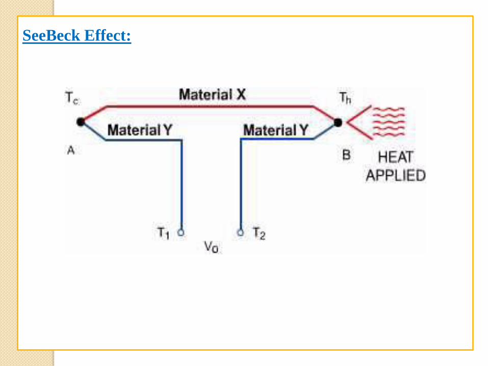
SeeBeck Effect:
In 1821, Thomas Seebeck found that an electric current would flow
continuously in a closed circuit made up of two dissimilar metals, if the
junctions of the metals were maintained at two different temperatures.
Thermoelectric power supply generators are based on the Seebeck effect
which is based on voltage generation along a conductor subjected to a gradient
of temperature.
When a temperature gradient is applied to a conductor, an electromotive force
is produced. The voltage difference generated is proportional to the
temperature difference across the thermoelectric module between the two
junctions, the hot and the cold one.
ΔV α ΔT
SeeBeck Effect:
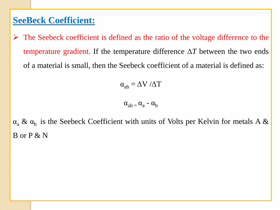
SeeBeck Coefficient:
The Seebeck coefficient is defined as the ratio of the voltage difference to the
temperature gradient. If the temperature difference ΔT between the two ends
of a material is small, then the Seebeck coefficient of a material is defined as:
αab = ΔV /ΔT
αab = αa - αb
αa & αb is the Seebeck Coefficient with units of Volts per Kelvin for metals A &
B or P & N
Peltier Effect:
In 1834, a French watchmaker and part time physicist, Jean Peltier found that
an electrical current would produce a temperature gradient at the junction of
two dissimilar metals.
The Peltier effect is the main contributor to all thermoelectric cooling
applications. It is responsible for heat removal and heat absorbance.
It states that when an electric current flows across two dissimilar conductors,
the junction of the conductors will either absorb or emit heat depending on the
flow of the electric current.
The heat absorbed or released at the junction is proportional to the input
electric current. The constant of proportionality is called the Peltier
coefficient.
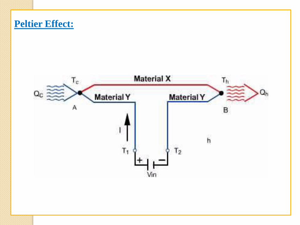
Peltier Effect:
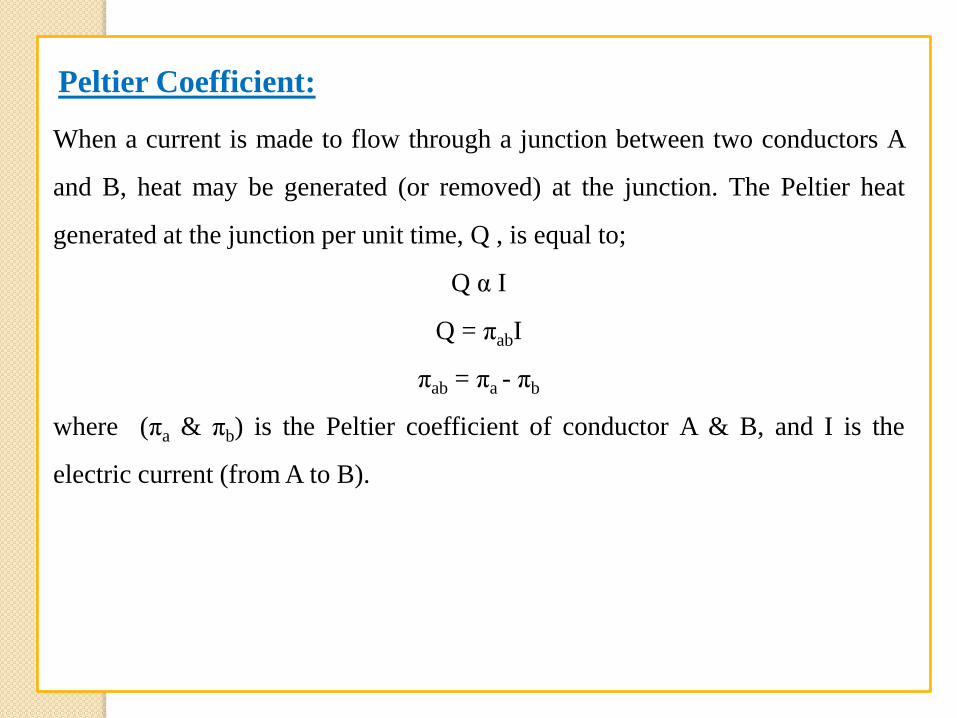
Peltier Coefficient:
When a current is made to flow through a junction between two conductors A
and B, heat may be generated (or removed) at the junction. The Peltier heat
generated at the junction per unit time, Q , is equal to;
Q α I
Q = πabI
πab = πa - πb
where (πa & πb) is the Peltier coefficient of conductor A & B, and I is the
electric current (from A to B).
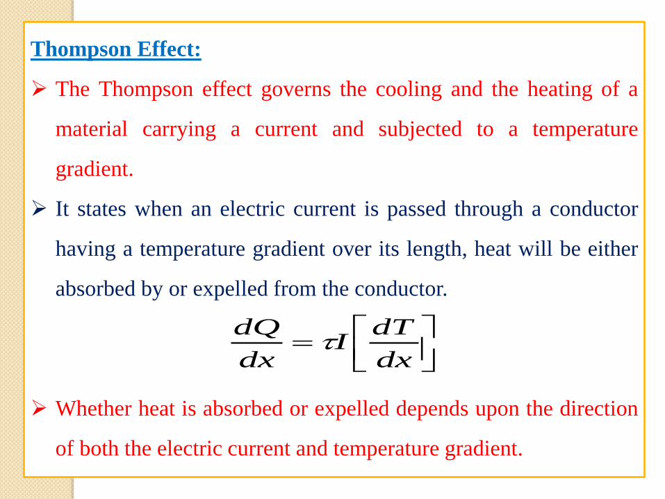
Thompson Effect:
The Thompson effect governs the cooling and the heating of a
material carrying a current and subjected to a temperature
gradient.
It states when an electric current is passed through a conductor
having a temperature gradient over its length, heat will be either
absorbed by or expelled from the conductor.
Whether heat is absorbed or expelled depends upon the direction
of both the electric current and temperature gradient.
dx
dTI
dx
dQ
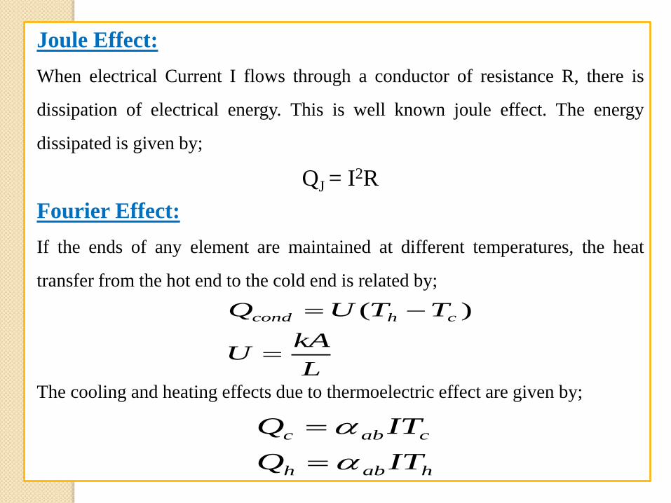
Joule Effect:
When electrical Current I flows through a conductor of resistance R, there is
dissipation of electrical energy. This is well known joule effect. The energy
dissipated is given by;
QJ = I2R
Fourier Effect:
If the ends of any element are maintained at different temperatures, the heat
transfer from the hot end to the cold end is related by;
The cooling and heating effects due to thermoelectric effect are given by;
L
kAU
TTUQ chcond
)(
habh
cabc
ITQ
ITQ
BASIC MECHANISM OF THERMOELECTRICS
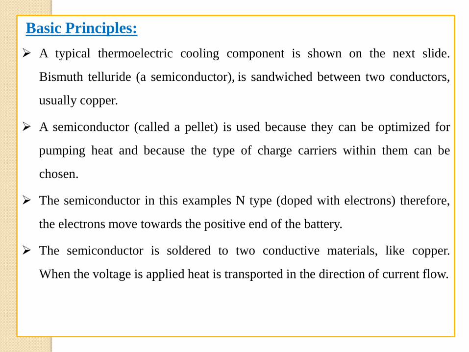
Basic Principles:
A typical thermoelectric cooling component is shown on the next slide.
Bismuth telluride (a semiconductor), is sandwiched between two conductors,
usually copper.
A semiconductor (called a pellet) is used because they can be optimized for
pumping heat and because the type of charge carriers within them can be
chosen.
The semiconductor in this examples N type (doped with electrons) therefore,
the electrons move towards the positive end of the battery.
The semiconductor is soldered to two conductive materials, like copper.
When the voltage is applied heat is transported in the direction of current flow.
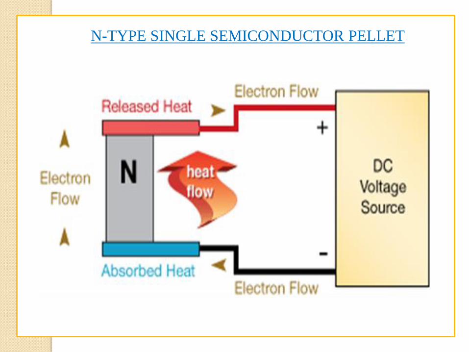
N-TYPE SINGLE SEMICONDUCTOR PELLET
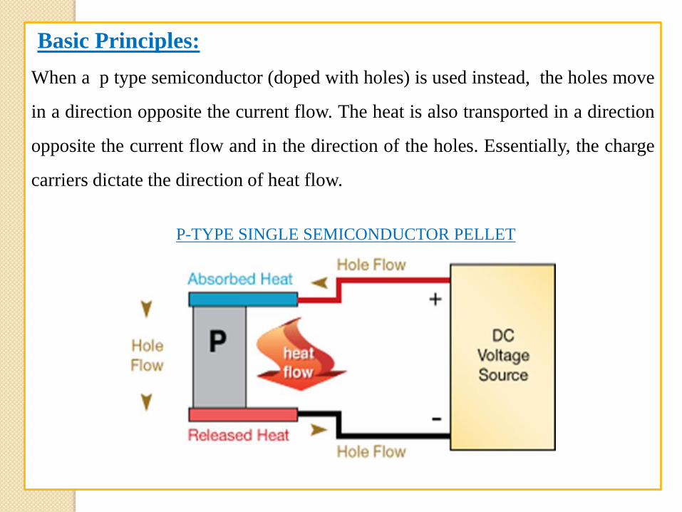
Basic Principles:
When a p type semiconductor (doped with holes) is used instead, the holes move
in a direction opposite the current flow. The heat is also transported in a direction
opposite the current flow and in the direction of the holes. Essentially, the charge
carriers dictate the direction of heat flow.
P-TYPE SINGLE SEMICONDUCTOR PELLET
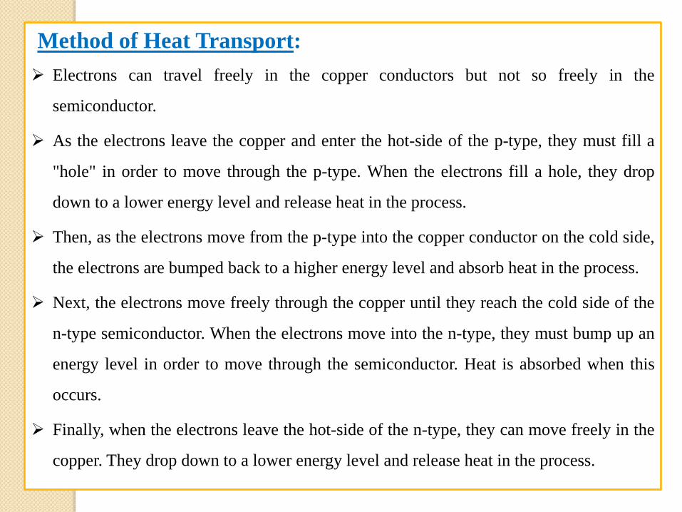
Method of Heat Transport:
Electrons can travel freely in the copper conductors but not so freely in the
semiconductor.
As the electrons leave the copper and enter the hot-side of the p-type, they must fill a
"hole" in order to move through the p-type. When the electrons fill a hole, they drop
down to a lower energy level and release heat in the process.
Then, as the electrons move from the p-type into the copper conductor on the cold side,
the electrons are bumped back to a higher energy level and absorb heat in the process.
Next, the electrons move freely through the copper until they reach the cold side of the
n-type semiconductor. When the electrons move into the n-type, they must bump up an
energy level in order to move through the semiconductor. Heat is absorbed when this
occurs.
Finally, when the electrons leave the hot-side of the n-type, they can move freely in the
copper. They drop down to a lower energy level and release heat in the process.
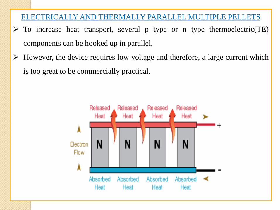
ELECTRICALLY AND THERMALLY PARALLEL MULTIPLE PELLETS
To increase heat transport, several p type or n type thermoelectric(TE)
components can be hooked up in parallel.
However, the device requires low voltage and therefore, a large current which
is too great to be commercially practical.
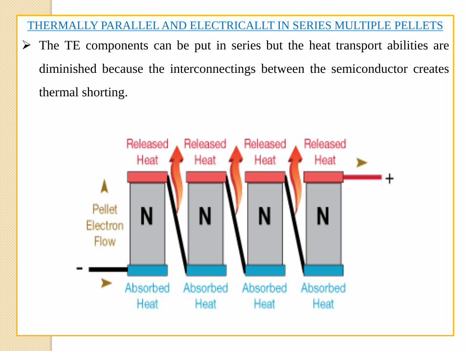
THERMALLY PARALLEL AND ELECTRICALLT IN SERIES MULTIPLE PELLETS
The TE components can be put in series but the heat transport abilities are
diminished because the interconnectings between the semiconductor creates
thermal shorting.
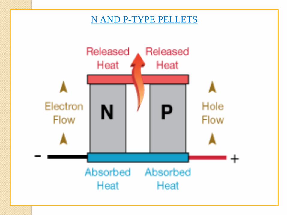
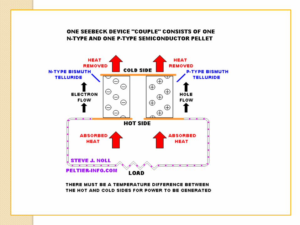
N AND P-TYPE PELLETS
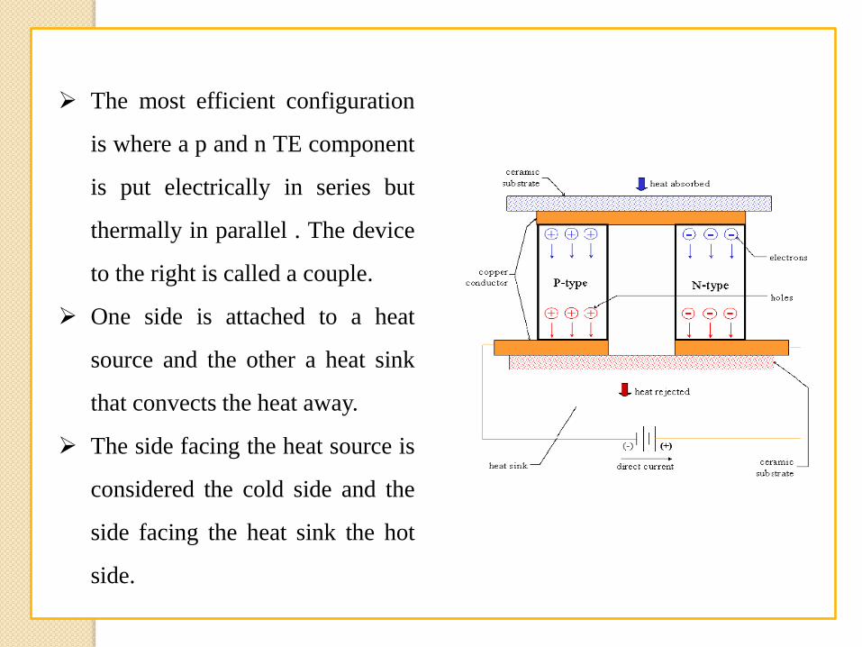
The most efficient configuration
is where a p and n TE component
is put electrically in series but
thermally in parallel . The device
to the right is called a couple.
One side is attached to a heat
source and the other a heat sink
that convects the heat away.
The side facing the heat source is
considered the cold side and the
side facing the heat sink the hot
side.
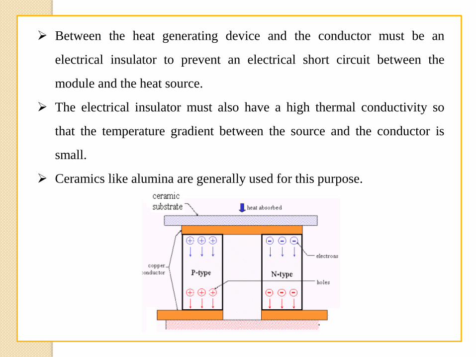
Between the heat generating device and the conductor must be an
electrical insulator to prevent an electrical short circuit between the
module and the heat source.
The electrical insulator must also have a high thermal conductivity so
that the temperature gradient between the source and the conductor is
small.
Ceramics like alumina are generally used for this purpose.
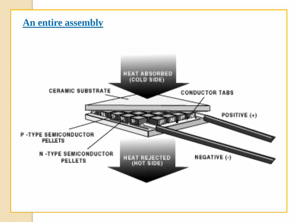
An entire assembly
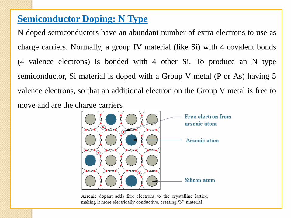
Semiconductor Doping: N Type
N doped semiconductors have an abundant number of extra electrons to use as
charge carriers. Normally, a group IV material (like Si) with 4 covalent bonds
(4 valence electrons) is bonded with 4 other Si. To produce an N type
semiconductor, Si material is doped with a Group V metal (P or As) having 5
valence electrons, so that an additional electron on the Group V metal is free to
move and are the charge carriers
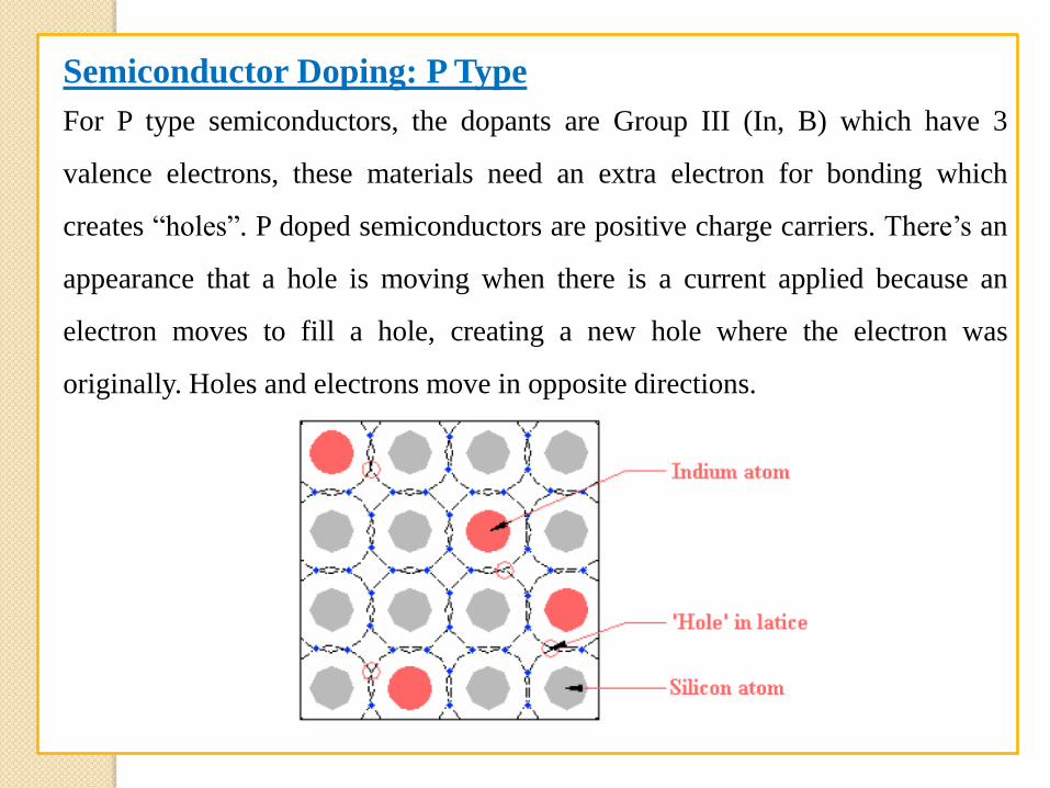
Semiconductor Doping: P Type
For P type semiconductors, the dopants are Group III (In, B) which have 3
valence electrons, these materials need an extra electron for bonding which
creates “holes”. P doped semiconductors are positive charge carriers. There’s an
appearance that a hole is moving when there is a current applied because an
electron moves to fill a hole, creating a new hole where the electron was
originally. Holes and electrons move in opposite directions.
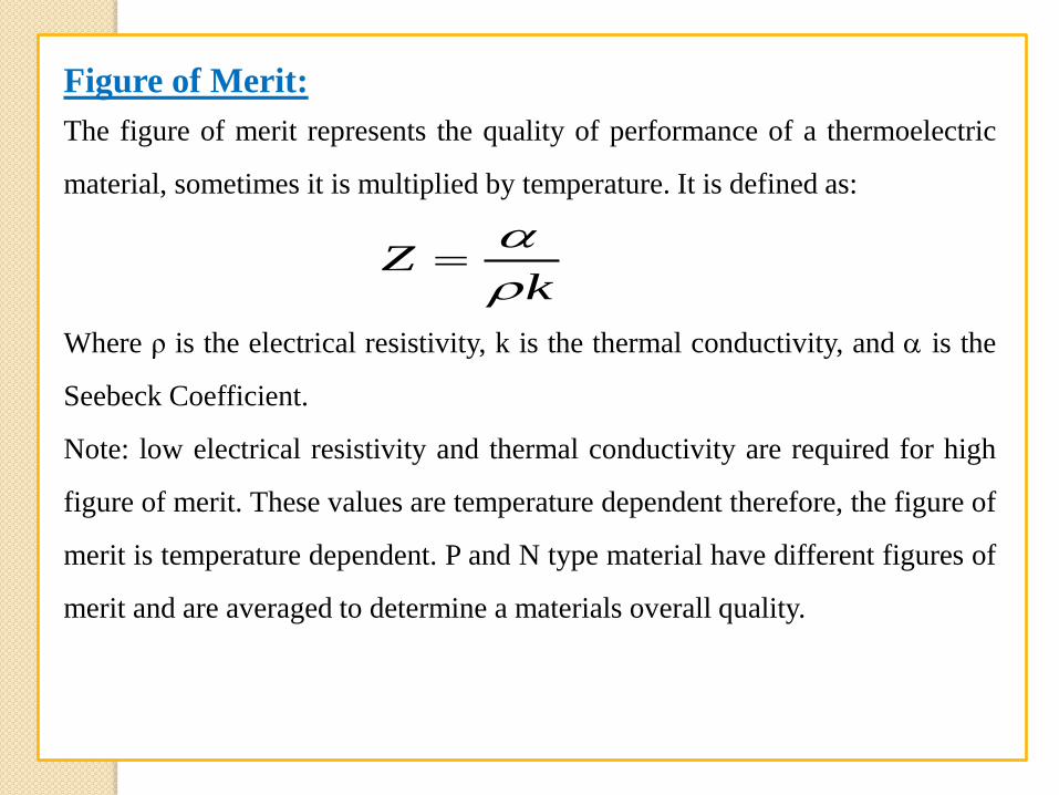
Figure of Merit:
The figure of merit represents the quality of performance of a thermoelectric
material, sometimes it is multiplied by temperature. It is defined as:
Where ρ is the electrical resistivity, k is the thermal conductivity, and is the
Seebeck Coefficient.
Note: low electrical resistivity and thermal conductivity are required for high
figure of merit. These values are temperature dependent therefore, the figure of
merit is temperature dependent. P and N type material have different figures of
merit and are averaged to determine a materials overall quality.
kZ
Thermoelectric Materials
Semiconductors are the optimum choice of material to sandwich between two
metal conductors because of the ability to control the semiconductors’ charge
carriers, as well as, increase the heat pumping ability.
The most commonly used semiconductor for electronics cooling applications
is Bi2Te3 because of its relatively high figure of merit. However, the
performance of this material is still relatively low and alternate materials are
being investigated with possibly better performance. Alternative materials
include:
Alternating thin film layers of Sb2Te3 and Bi2Te3.
Lead telluride and its alloys
SiGe
Materials based on nanotechnology
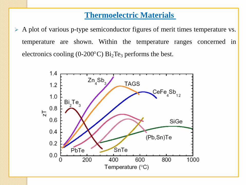
Thermoelectric Materials
A plot of various p-type semiconductor figures of merit times temperature vs.
temperature are shown. Within the temperature ranges concerned in
electronics cooling (0-200C) Bi2Te3 performs the best.
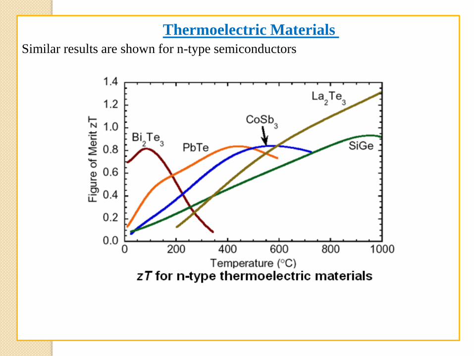
Similar results are shown for n-type semiconductors
Thermoelectric Materials
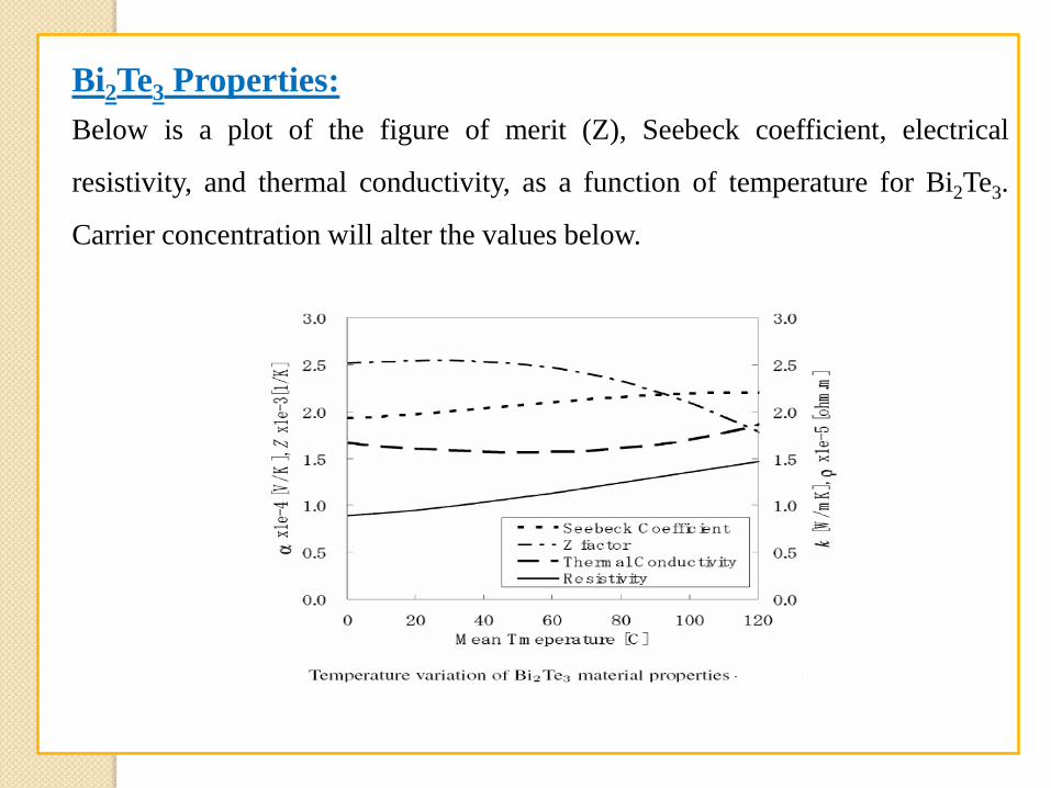
Bi2Te3 Properties:
Below is a plot of the figure of merit (Z), Seebeck coefficient, electrical
resistivity, and thermal conductivity, as a function of temperature for Bi2Te3.
Carrier concentration will alter the values below.
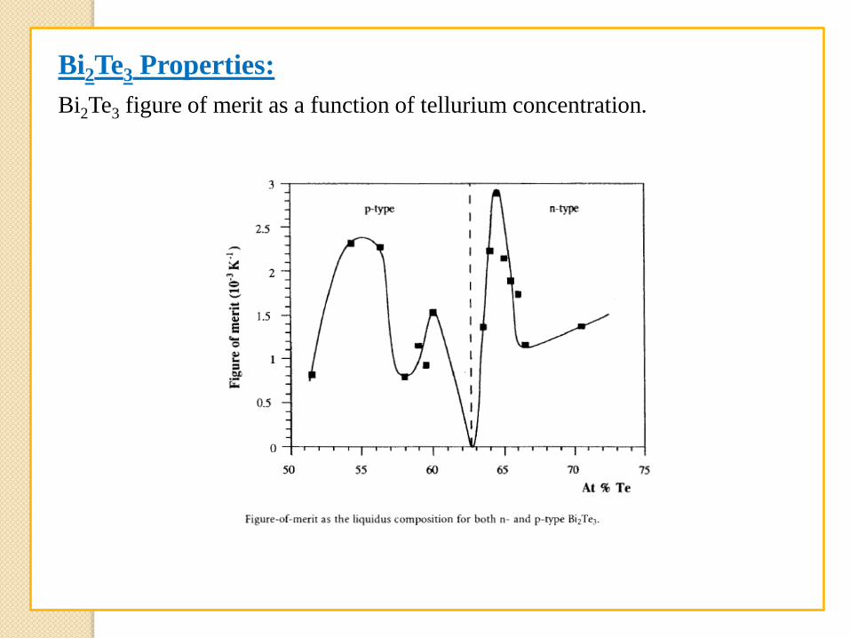
Bi2Te3 Properties:
Bi2Te3 figure of merit as a function of tellurium concentration.
Thermoelectric Materials
Metals are used to sandwich the semiconductor. Because the TE performance
is also dependent on these materials, an optimal material must be chosen,
usually copper.
A common problem with TE cooling is that condensation may occur causing
corrosion and eroding the TE’s inherent reliability.
Condensation occurs when the dew point is reached. The dew point is the
temperature to which air must be cooled at constant pressure for the water
vapor to start to condense
Condensation occurs because the air loses the ability to carry the water vapor
that condenses. As the air’s temperature decreases its water vapor carrying
capacity decreases.
Since TE coolers can cool to low and even below ambient temperatures,
condensation is a problem. The most common sealant employed is silicon
rubber. Research has been performed to determine the most effective sealing
agent used to protect the chip from water.
Condensation
Condensation
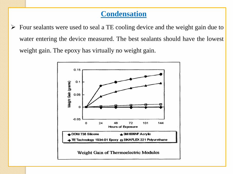
Four sealants were used to seal a TE cooling device and the weight gain due to
water entering the device measured. The best sealants should have the lowest
weight gain. The epoxy has virtually no weight gain.
Condensation
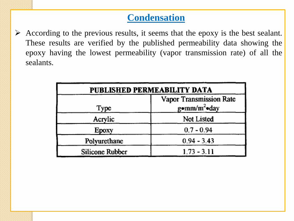
According to the previous results, it seems that the epoxy is the best sealant.
These results are verified by the published permeability data showing the
epoxy having the lowest permeability (vapor transmission rate) of all the
sealants.
Thermoelectric Performance
TE performance depends on the following factors:
The temperature of the cold and hot sides.
Thermal and electrical conductivities of the device’s materials.
Contact resistance between the TE device and heat source/heat sink.
Thermal resistance of the heat sink.
Thermoelectric Performance
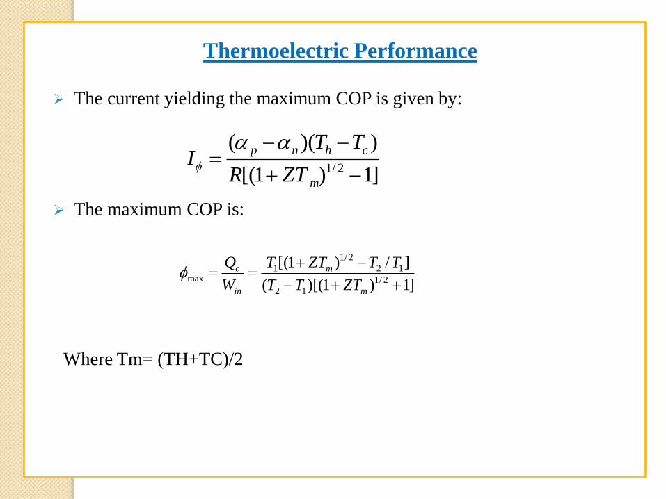
The current yielding the maximum COP is given by:
The maximum COP is:
]1)1[(
))((2/1
m
chnp
ZTR
TTI
]1)1)[((
]/)1[(2/1
12
12
2/1
1max
m
m
in
c
ZTTT
TTZTT
W
Q
Where Tm= (TH+TC)/2
Thermoelectric Performance
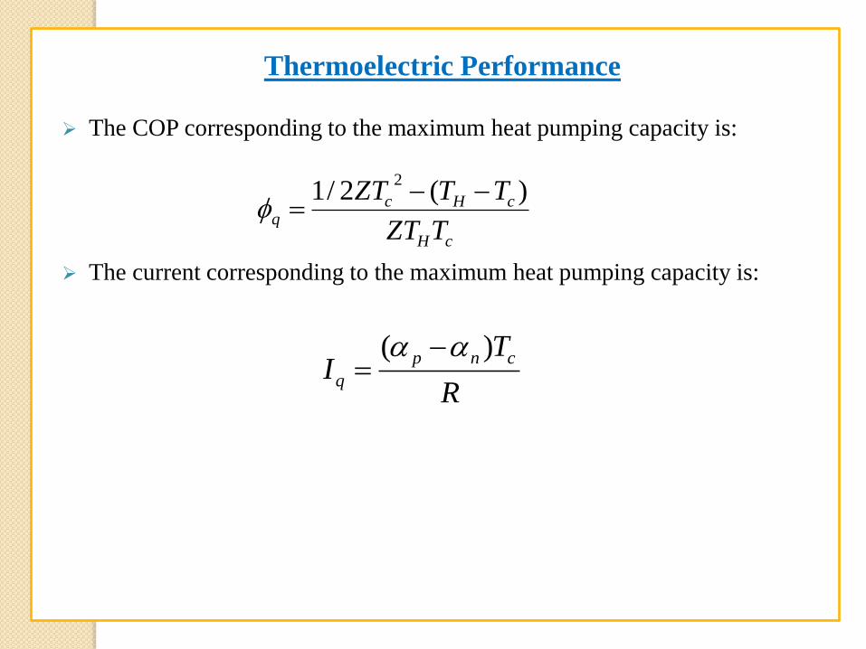
The COP corresponding to the maximum heat pumping capacity is:
The current corresponding to the maximum heat pumping capacity is:
cH
cHcq
TZT
TTZT )(2/12
R
TI
cnp
q
)(
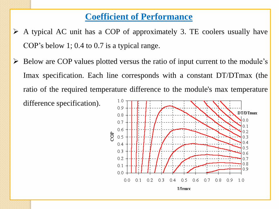
A typical AC unit has a COP of approximately 3. TE coolers usually have
COP’s below 1; 0.4 to 0.7 is a typical range.
Below are COP values plotted versus the ratio of input current to the module’s
Imax specification. Each line corresponds with a constant DT/DTmax (the
ratio of the required temperature difference to the module's max temperature
difference specification).
Coefficient of Performance
Thermoelectric Performance
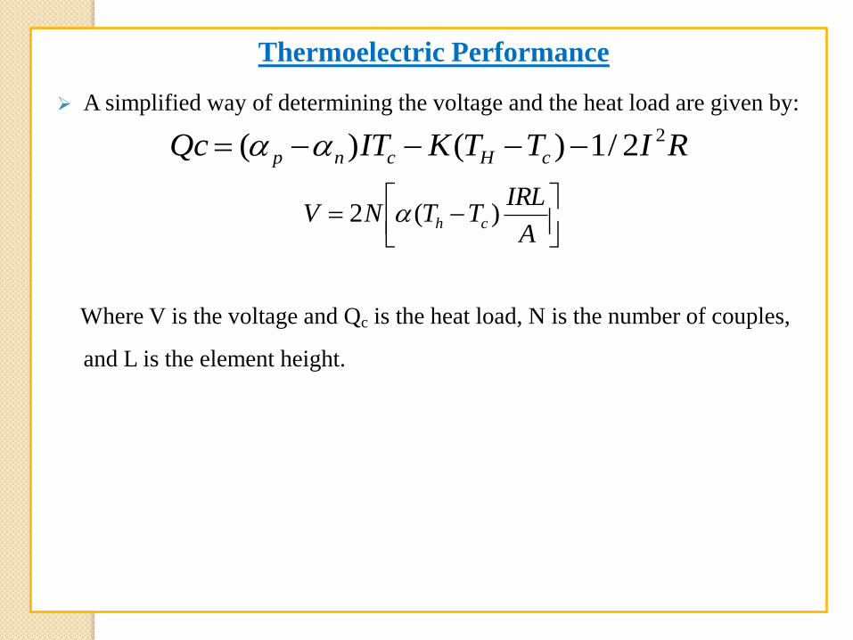
A simplified way of determining the voltage and the heat load are given by:
Where V is the voltage and Qc is the heat load, N is the number of couples,
and L is the element height.
A
IRLTTNV ch )(2
RITTKITQc cHcnp
22/1)()(
Improving TE performance
Various methods have been used to improve the performance of TE coolers
which are its major drawback.
Examples: thin film coolers or multistage (bulk) coolers.
Thin Film Coolers
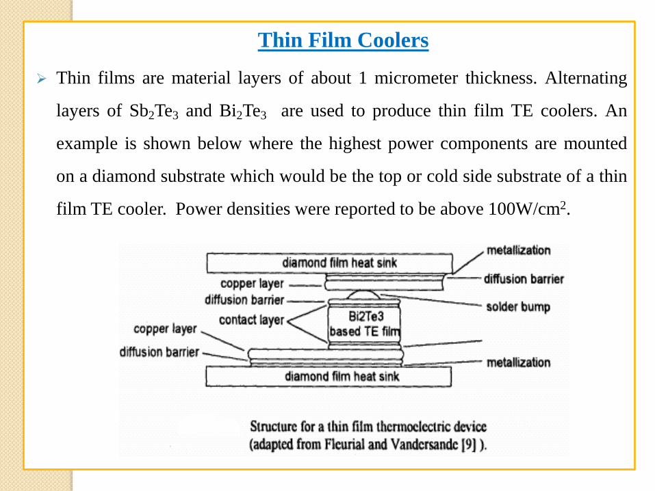
Thin films are material layers of about 1 micrometer thickness. Alternating
layers of Sb2Te3 and Bi2Te3 are used to produce thin film TE coolers. An
example is shown below where the highest power components are mounted
on a diamond substrate which would be the top or cold side substrate of a thin
film TE cooler. Power densities were reported to be above 100W/cm2.
Thin Film Coolers
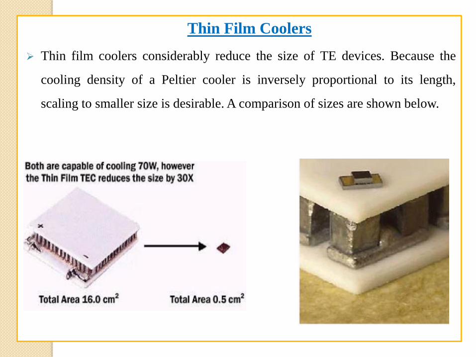
Thin film coolers considerably reduce the size of TE devices. Because the
cooling density of a Peltier cooler is inversely proportional to its length,
scaling to smaller size is desirable. A comparison of sizes are shown below.
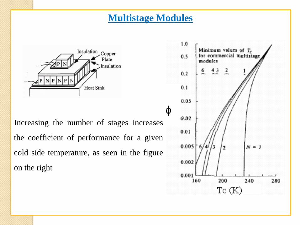
When the desired temperature differential between the cold and hot side
cannot be obtained with a single stage module, or when the cold side
temperature must be lower than a one stage cooler will allow, a multistage
module may need to be applied.
Multistage modules are essentially single stage modules stacked up in a
vertical pyramid-shaped array (see next slide).
As the number of stages increases, the minimum cold side temperature will
decrease (Rowe, 1995) .
Also, increasing the number of stages increases the coefficient of performance
for a given cold side temperature
Multistage Modules
Multistage Modules
Increasing the number of stages increases
the coefficient of performance for a given
cold side temperature, as seen in the figure
on the right
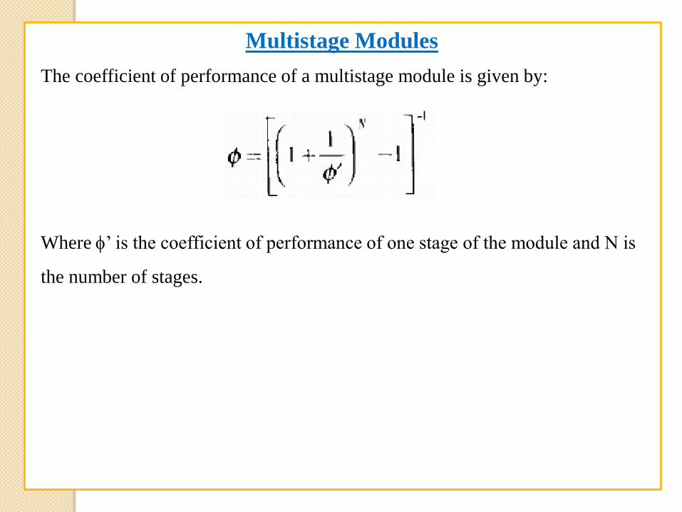
The coefficient of performance of a multistage module is given by:
Where ’ is the coefficient of performance of one stage of the module and N is
the number of stages.
Multistage Modules
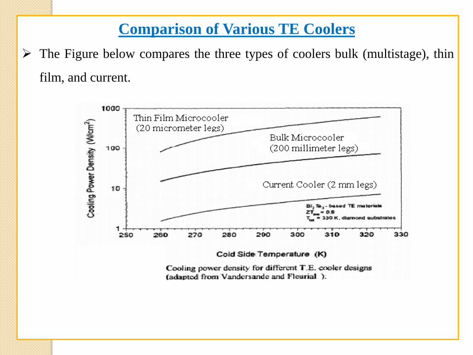
The Figure below compares the three types of coolers bulk (multistage), thin
film, and current.
Comparison of Various TE Coolers
More exotic TE devices are being researched that could result in better
performance such as, superlattice structures, quantum wires and quantum wells,
thin films using SiGe/Si, and thermionic cooling. However, research in these are
preliminary and are not in widespread use.
Improving Performance
TE cooling provides high degrees of temperature stability because the amount
of cooling it provides is proportional to the applied current.
The reported temperature stability of a TE device has been ±.0003 degrees
Celsius but considerable effort had to be used for this level of stability.
Several factors are involved in the temperature stability:
The controller and its resolution.
The response time of the specific cooling assembly
The response time of the object being cooled.
Temperature stability
TE cooling devices are favorable in electronics cooling systems because of
their high reliability, flexibility in packaging and integration, low weight and
ability to maintain a low junction temperature, even below ambient
temperature.
Also, other cooling devices that can fit the tiny spaces required for electronics
cooling, such as, a capillary loop heat or a miniature scale vapor compression
refrigerator are not commercially available.
Disadvantages of these devices are the limit to their cooling capacity limit and
coefficient of performance which may be restrictive in the future when heat
transfer demands become much larger.
Typical TE cooling schemes have a TE device attached to a heat source (the
cold side) that transports heat to a heat sink (the warm side).
TE Cooling of Electronics
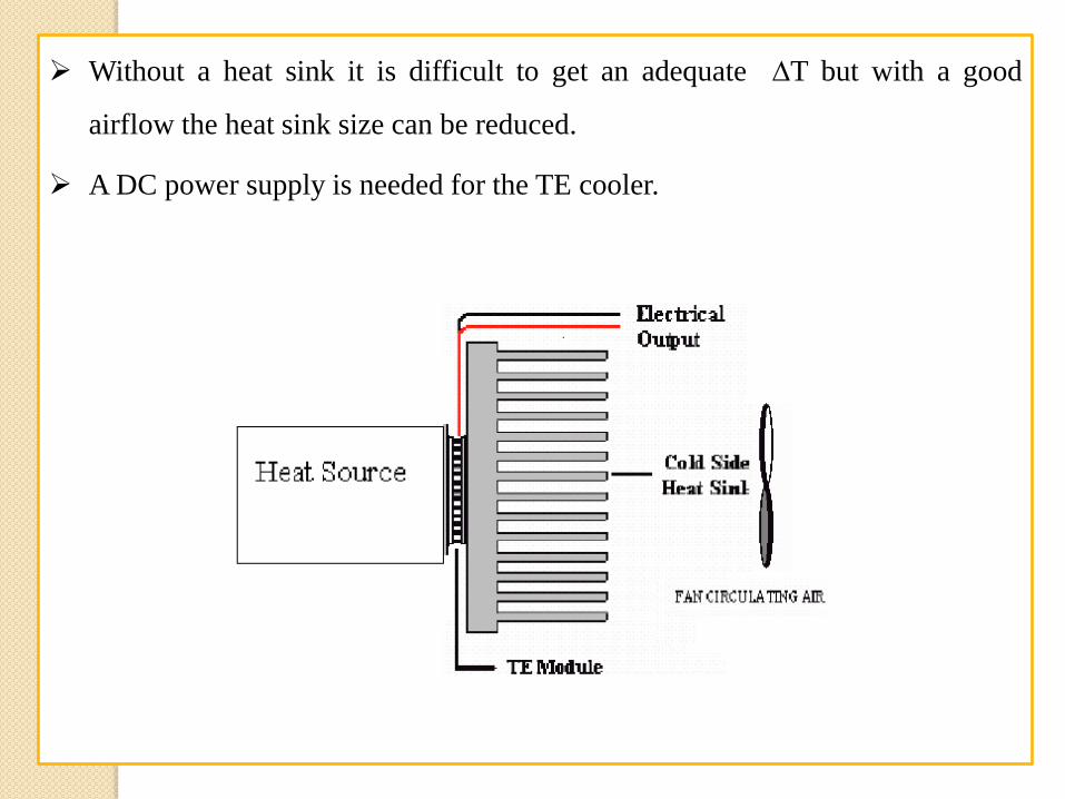
Without a heat sink it is difficult to get an adequate T but with a good
airflow the heat sink size can be reduced.
A DC power supply is needed for the TE cooler.
MAJOR APPLICATIONS OF THERMOELECTRIC COOLERS
Include equipment used by military, medical, industrial,
consumer, scientific/laboratory, and telecommunications
organizations.
Uses range from simple food and beverage coolers for an
afternoon picnic to extremely sophisticated temperature control
systems in missiles and space vehicles.
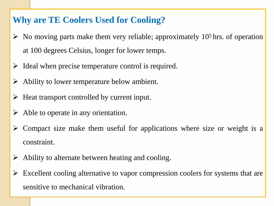
Why are TE Coolers Used for Cooling?
No moving parts make them very reliable; approximately 105 hrs. of operation
at 100 degrees Celsius, longer for lower temps.
Ideal when precise temperature control is required.
Ability to lower temperature below ambient.
Heat transport controlled by current input.
Able to operate in any orientation.
Compact size make them useful for applications where size or weight is a
constraint.
Ability to alternate between heating and cooling.
Excellent cooling alternative to vapor compression coolers for systems that are
sensitive to mechanical vibration.
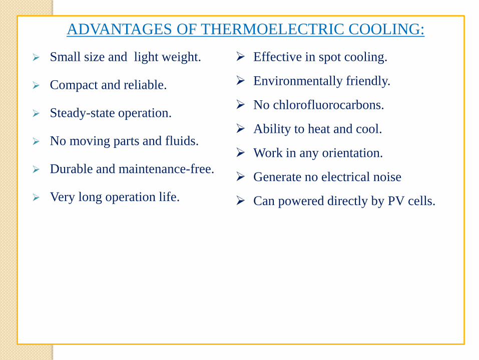
ADVANTAGES OF THERMOELECTRIC COOLING:
Effective in spot cooling.
Environmentally friendly.
No chlorofluorocarbons.
Ability to heat and cool.
Work in any orientation.
Generate no electrical noise
Can powered directly by PV cells.
Small size and light weight.
Compact and reliable.
Steady-state operation.
No moving parts and fluids.
Durable and maintenance-free.
Very long operation life.
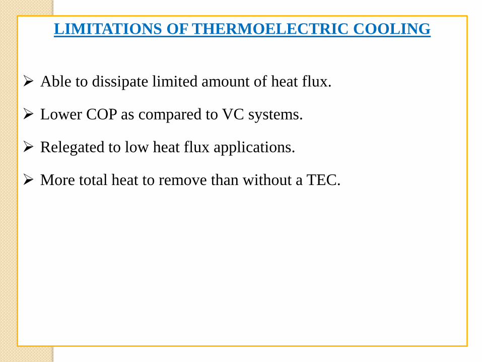
LIMITATIONS OF THERMOELECTRIC COOLING
Able to dissipate limited amount of heat flux.
Lower COP as compared to VC systems.
Relegated to low heat flux applications.
More total heat to remove than without a TEC.
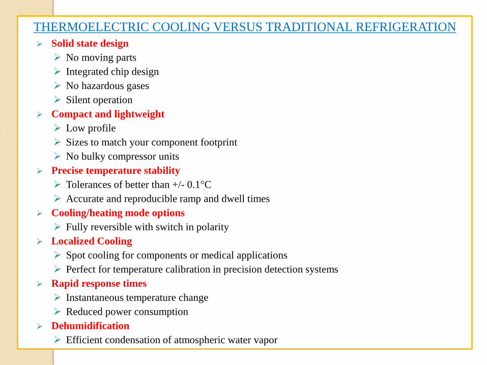
THERMOELECTRIC COOLING VERSUS TRADITIONAL REFRIGERATION
Solid state design
No moving parts
Integrated chip design
No hazardous gases
Silent operation
Compact and lightweight
Low profile
Sizes to match your component footprint
No bulky compressor units
Precise temperature stability
Tolerances of better than +/- 0.1°C
Accurate and reproducible ramp and dwell times
Cooling/heating mode options
Fully reversible with switch in polarity
Localized Cooling
Spot cooling for components or medical applications
Perfect for temperature calibration in precision detection systems
Rapid response times
Instantaneous temperature change
Reduced power consumption
Dehumidification
Efficient condensation of atmospheric water vapor