thermo-mixed hydrodynamics of piston compression ... · thermo-mixed hydrodynamics of piston...
TRANSCRIPT

Loughborough UniversityInstitutional Repository
Thermo-mixedhydrodynamics of piston
compression ringconjunction
This item was submitted to Loughborough University's Institutional Repositoryby the/an author.
Citation: SHAHMOHAMADI, H. ... et al, 2013. Thermo-mixed hydrodynam-ics of piston compression ring conjunction. Tribology Letters, 51 (3), pp.323-340.
Additional Information:
• The final publication is available at http://link.springer.com.
Metadata Record: https://dspace.lboro.ac.uk/2134/12900
Version: Accepted for publication
Please cite the published version.

This item was submitted to Loughborough’s Institutional Repository
(https://dspace.lboro.ac.uk/) by the author and is made available under the following Creative Commons Licence conditions.
For the full text of this licence, please go to: http://creativecommons.org/licenses/by-nc-nd/2.5/

Tribology Letters, June 2013, DOI: 10.1007/s11249-013-0163-5
(Accepted Version)
1
Thermo-mixed hydrodynamics of Piston Compression Ring Conjunction
H. Shahmohamadi, R. Rahmani*, H. Rahnejat, C.P. Garner and P.D. King
Wolfson School of Mechanical and Manufacturing Engineering, Loughborough University,
Loughborough, LE11 3TU, Leicestershire, UK
*Corresponding author, Email: [email protected]
Abstract
A new method, comprising Navier-Stokes equations, Rayleigh-Plesset volume fraction
equation, an analytical control-volume thermal mixed approach and asperity interactions is
reported. The method is employed for prediction of lubricant flow and assessment of friction
in the compression ring-cylinder liner conjunction. The results are compared with Reynolds-
based laminar flow with Elrod cavitation algorithm. Good conformance is observed for
medium load intensity part of the engine cycle. At lighter loads and higher sliding velocity,
the new method shows more complex fluid flow, possessing layered flow characteristics on
account of pressure and temperature gradient into the depth of the lubricant film, which leads
to a cavitation region with vapour content at varied volume fractions. Predictions also
conform well to experimental measurements reported by other authors.
Keywords: Piston Ring conjunction, mixed mode friction, Navier-Stokes equations, Raleigh-
Plesset volume fraction
1. Introduction
The primary function of the piston compression ring is to seal the combustion chamber. This
prevents the escape of high-pressure gases from the combustion chamber and conversely
lubricant leakage into the chamber. However, effective sealing function of the compression
ring can result in increased friction and thus parasitic losses [1].The piston assembly accounts
for approximately 35-45% of engine frictional losses [2, 3]. Therefore, in order to improve
engine performance as well as reducing emission levels, it is important to have a deeper
understanding of frictional behaviour of piston-cylinder system as a prerequisite. The current

Tribology Letters, June 2013, DOI: 10.1007/s11249-013-0163-5
(Accepted Version)
2
work addresses these issues with regard to the piston compression ring.
There have been many numerical predictions of compression ring-cylinder liner conjunction,
where the analyses have included a host of parameters which interact with each other, making
the tribology of ring-liner conjunction particularly complex. These parameters include the
effect of the ring’s axial profile along its contacting face-width with the cylinder liner and its
surface topography [4], and the effect of evolving wear process upon friction and sealing
effectiveness of the ring in an out-of-round bore [5,6]. These and similar analyses [7-13] have
included mixed regime of lubrication, where direct interaction of surfaces can occur at piston
dead centre reversals with momentary cessation of lubricant entraining motion into the
contact under assumed fully flooded or starved inlet conditions. Although ring fitment
analysis is taken into account in the works reported in [5,6,11,12], including in some cases
with bore out-of-roundness, the ring bore conformability should also take into account the
modal behaviour of the ring as described, for example, by Baker et al [14]. They showed that
ring elastodynamics in fact conforms it to the bore in the high pressure region with a low
sliding velocity (i.e. at the reversals). This ensures good ring sealing at the expense of
increased friction. However, in some parts of the engine cycle, ring elastodynamics as well as
its axial profile can exacerbate the convergent-divergent conjunctional passage and clearance,
which suggests lubricant film rupture and the emergence of a cavitation region. This can also
affect the compression ring sealing function. The effect of cavitation is studied by Chong et al
[15], who used Elrod’s approximation [16] to the Jakobsson and Floberg [17] and Olsson
[18] (JFO) cavitation boundary condition. Chong et al [15] showed that cavitation formed at
the lubricant film contact exit in the compression stroke reduces the lubricant availability at
the TDC (Top Dead Centre) reversal, thus causing a starved contact in parts of the power
stroke in the vicinity of the TDC.
Therefore, the multivariate nature of the problem is quite apparent. The current analysis
combines the use of an open (free) exit boundary condition instead of an imposed cavitation
boundary condition. This is achieved by solving the Navier-Stokes equations for multi-phase
flow dynamics instead of the usual Reynolds equation. Additionally, this approach readily
enables simultaneous solution with the energy equation. Thus, the effect of surface
temperatures, and that caused through viscous shear of the lubricant in the conjunction, upon
lubricant film formation and viscosity variation into the depth of the film are included in the
solution. Unlike Reynolds or Elrod flow equations, with the Navier-Stokes equations the
Tribology Letters, June 2013, DOI: 10.1007/s11249-013-0163-5
(Accepted Version)
3
pressure gradient across the film is retained. This enables more accurate prediction of viscous
friction due to Poiseuille flow as well as in Couette shear. This approach together with
inclusion of lubricant rheological state and asperity interactions, to represent boundary
friction, has not hitherto been reported in literature.
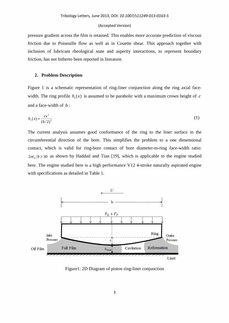
2. Problem Description
Figure 1 is a schematic representation of ring-liner conjunction along the ring axial face-
width. The ring profile )(xhs is assumed to be parabolic with a maximum crown height of c
and a face-width of b :
2
2
)2/()(
bcxxhs = (1)
The current analysis assumes good conformance of the ring to the liner surface in the
circumferential direction of the bore. This simplifies the problem to a one dimensional
contact, which is valid for ring-bore contact of bore diameter-to-ring face-width ratio:
302 0 ≥brπ as shown by Haddad and Tian [19], which is applicable to the engine studied
here. The engine studied here is a high performance V12 4-stroke naturally aspirated engine
with specifications as detailed in Table 1.
Figure1: 2D Diagram of piston ring-liner conjunction
Tribology Letters, June 2013, DOI: 10.1007/s11249-013-0163-5
(Accepted Version)
4
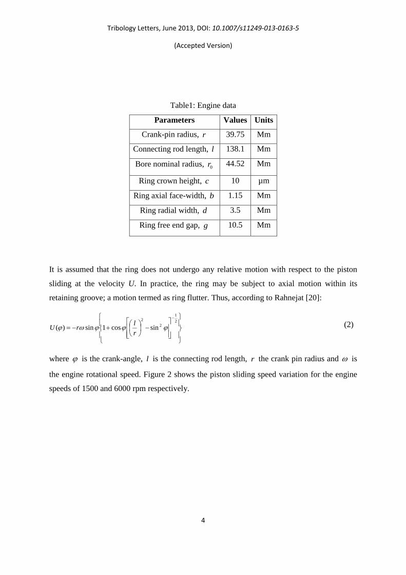
Table1: Engine data
Parameters Values Units
Crank-pin radius, r 39.75 Mm
Connecting rod length, l 138.1 Mm
Bore nominal radius, 0r 44.52 Mm
Ring crown height, c 10 µm
Ring axial face-width, b 1.15 Mm
Ring radial width, d 3.5 Mm
Ring free end gap, g 10.5 Mm
It is assumed that the ring does not undergo any relative motion with respect to the piston
sliding at the velocity U. In practice, the ring may be subject to axial motion within its
retaining groove; a motion termed as ring flutter. Thus, according to Rahnejat [20]:
−
+−=
−21
22
sincos1sin)( ϕϕϕωϕrlrU (2)
where ϕ is the crank-angle, l is the connecting rod length, r the crank pin radius and ω is
the engine rotational speed. Figure 2 shows the piston sliding speed variation for the engine
speeds of 1500 and 6000 rpm respectively.

Tribology Letters, June 2013, DOI: 10.1007/s11249-013-0163-5
(Accepted Version)
5
Figure 2: piston sliding speed for engine speeds of 1500 and 6000 rpm
Forces acting on the ring are considered as radial in-plane forces. In its radial plane, the ring
is subjected to two outward forces: ring elastic tension force TF and the gas force GF , acting
on the inner rim of the ring. These forces strive to conform the ring to the bore surface. Thus,
the total outward force (towards the liner interface), acting on the ring is: GT FFF += . The
ring tension force, TF , is obtained as [21]:
0rbpF eT = )3
where( 40br
gEIpe π= (3)
where, ep is the elastic pressure, 0r is the bore nominal radius and g is the ring end gap in
its free (unfitted) state. The gas force acting on the back of the ring varies according to the
chamber pressure in an engine cycle, thus:
)(2)( 0 ϕπϕ gG pbrF = (4)
A gas blow-by analysis is required to obtain the exact value of gas pressure acting behind the
ring. In the current analysis it is assumed that the gas pressure behind the ring is equal to the
in-cylinder gas pressure.
Tribology Letters, June 2013, DOI: 10.1007/s11249-013-0163-5
(Accepted Version)
6
These outward forces (ring elastic tension and the gas force) are opposed by the contact force
generated as the result of combined actions of generated conjunctional hydrodynamic
pressures and the load share carried by the direct contact of surfaces themselves. The latter is
often the load shared by a small portion of asperities on the opposing surfaces. Thus, the
instantaneous contact load is determined as )()()( ϕϕϕ ha WWW += , where the load carried
by any film of lubricant is the integrated pressure distribution as:
0 0( ) 2 ( )
b
h hW r p dxdyφ π φ= ∫ (5)
As shown in Figure 1, in general, the contact region may be considered as comprising of
three distinct regions: (i) full film (a coherent lubricant film region), (ii) film rupture and
cavitation, and (iii) lubricant film reformation. The Elrod cavitation model is the usual basis
for the tribological analysis, taking into account these various conjunctional regions. To
describe the physics of fluid flow in the cavitated region, in which at least these various states
of lubricant film co-exist, a suitable two-phase flow model needs to be employed alongside
the use of the Navier-Stokes equations. This would be an elegant approach which for
moderately and heavily loaded conditions represents a reasonable compromise between
computational speed and predictive accuracy [22]. However, it can be fairly complex to
implement.
3. Numerical Model
3.1. General Navier-Stokes and energy equations
The general continuity and Navier-Stokes momentum equations for compressible viscous
fluid flow can be described as [23]:
0. =∇+ VDtD
ρρ (6)
FpDt
VDij
+∇+−∇= )(. τρ (7)
where DtD is the covariant derivative operator, ρ is the lubricant density, p is the pressure,
ijτ is the viscous stress tensor and F
is the body force field vector. In addition,

Tribology Letters, June 2013, DOI: 10.1007/s11249-013-0163-5
(Accepted Version)
7
ˆˆ ˆV Ui Vj Wk= + +
is the velocity vector in which U is the component of velocity in the
direction of axial lubricant flow entrainment, V is that in the side-leakage direction; along
the y -axis (which may reasonably be discarded as there is negligible side-leakage in the thin
film ring-bore conjunction), and W is the squeeze film velocity, ht
∂∂
. The viscous stress
tensor is:
2 .3
jiij ij
j i
UU Vx x
τ η δ ∂∂
= + − ∇ ∂ ∂
(8)
where η is the effective lubricant dynamic viscosity, ijδ is the Kronecker delta and it is
defined as:
=≠
=jiji
ij if1 if0
δ (9)
One possibility in a CFD model is to evaluate fluid viscosity as a function of pressure and
temperature along the liner and into the depth of the lubricant film. The latter is neglected in
the conventional hydrodynamic lubrication approaches, which are based on Reynolds
equation. Finally, the energy equation can be stated as [23]:
.( ) iij
j
UDH Dp kDt Dt x
ρ θ τ ∂= +∇ ∇ +
∂ (10)
where H is the fluid enthalpy, θ is the temperature and k is the lubricant thermal
conductivity.
3.2. Cavitation model – vapour mass fraction and vapour transport equations
With cavitation, the liquid-vapour mass transfer (evaporation and condensation) is governed
by the vapour transport equation as [24]:
cevvvv RRVt
−=∇+∂∂ )(.)( υραρα
(11)
where vρ is the vapour density, υV
is the velocity vector of the vapour phase, eR and cR are
mass transfer source terms related to the growth and collapse of the vapour bubbles
respectively. The growth and collapse of a bubble cluster are modelled based on the
Rayleigh-Plesset equation, describing the growth of a single vapour bubble in a liquid, which

Tribology Letters, June 2013, DOI: 10.1007/s11249-013-0163-5
(Accepted Version)
8
provides the rate equation, controlling vapour generation and condensation. Singhal et al [25]
assumed that a working fluid is a mixture of liquid and vapour and introduced a modified
form of the above equation, based upon the vapour mass fraction, massf as:
cemassmassmmassm RRffVft
−+∇Γ∇=∇+∂∂ )(.)(.)( υρρ
(12)
where mρ is the mixture density and Γ is the diffusion coefficient. The mass transfer rate
expressions are derived from the Rayleigh-Plesset equations, based upon limiting bubble size
considerations (interface surface area per unit volume of vapour). These rates are functions of
the instantaneous, local pressure and are given by:
satmassl
satl
s
chee ppfppVCR <−
−= for ),1(
3)(2
ρρρ
σ υ (13)
satmassl
satl
s
chcc ppfppVCR >
−= for ,
3)(2
ρρρ
σ υ (14)
where the suffices l and υ denote the liquid and vapour phases respectively, chV is a
characteristic velocity, sσ is the surface tension coefficient of the liquid, satp is the liquid
saturation vaporisation pressure at a given temperature and eC and cC are empirical
constants and are considered to be 50 and 0.01 respectively according to Kubota et al [26].
3.3. Conventional hydrodynamic cavitation model (Elrod’s method)
For the engine under investigation, the ring perimeter-to-width ratio is over 100. Therefore,
as a first approximation, the piston ring/liner conjunction can be viewed as an infinitely long
slider bearing [7] (envisaged as unwrapped). Although this assumes uniform radial loading
and neglects piston secondary motion as well as ring dynamics, the final results can provide
some valuable predictions. If the flow is considered as laminar, the behaviour of most
lubricated conjunctions can be predicted using Reynolds equation:
( ) )(26
3h
dtdh
xU
xph
xρρ
ηρ
+∂∂
=
∂∂
∂∂ (15)
Elrod’s modification [16] provides an acceptable solution if cavitation is present: In the full
film region of the contact both Couette and Poiseuille terms are considered, while in the

Tribology Letters, June 2013, DOI: 10.1007/s11249-013-0163-5
(Accepted Version)
9
cavitation region only Couette flow is taken into account and lubricant squeeze film motion
[27]. To account for this, a switching term, sg is defined as:
1 if 1 (full film region)0 if 0< <1 (cavitation region)sg
ξξ≥
=
(16)
in which ξ is defined as the fractional film content. This allows defining the contact pressure
distribution as a function of film ratio ξ as:
cs pgp += ξβ ln (17)
where cp is the lubricant’s cavitation vaporisation pressure and β is the lubricant’s bulk
modulus. Reynolds equation is now modified using equations (15) and (17) as:
( ) )(26
3h
dtdh
xU
xg
hx s ξρξρξβ
ηρ
+∂∂
=
∂∂
∂∂ (18)
Lubricant viscosity and density vary with contact pressures and temperatures as described in
Section 3.5 below.
3.4. Boundary conditions
In both the Navier-Stokes and Elrod’s models the following boundary conditions are used
along the axial x-direction of the contact (i.e. along the ring face-width)
==+=−
cch
Uh
Lh
pxppbppbp
)()2/()2/(
(19)
However, the Elrod model satisfies another pressure gradient boundary condition
0)(=
= cxxdxxdp at the film rupture point ( cx is the location of rupture point), whereas no
artificial exit boundary condition needs to be stated with the Navier-Stokes approach.
3.5. Lubricant rheology
The lubricant bulk rheological properties including density and viscosity are affected by
pressure and temperature [5]. The density–pressure relationship is [28]:

Tribology Letters, June 2013, DOI: 10.1007/s11249-013-0163-5
(Accepted Version)
10
[ ])(1065.01)(107.11
)(100.61 0
39
10
0 Θ−Θ×−
−×+−×
+= −−
−
atmh
atmh
pppp
ρρ (20)
in which atmp is the atmospheric pressure and 0Θ is temperature in K (i.e. )27300 +=Θ θ .
Lubricant density at atmospheric pressure, 0ρ , is given in Table 2.
Variations of lubricant dynamic viscosity with pressure and temperature can be expressed
based on Roelands’ equation [29] and further developed by Houpert [30], as follows:
( )
−
×−
+
−Θ−Θ
+=−
11098.1
1138
13867.9)ln(exp 80
00
0 Zatmh
Spp
ηηη (21)
in which, 0η is the lubricant dynamic viscosity at atmospheric pressure and temperature, and
Z and 0S are constants:
]67.9)[ln(101.5 09
0
+×=
− ηα
Z and 67.9)ln(
)138(
0
000 +
−Θ=
ηβS (22)
where 0α and 0β are constants at atmospheric temperature and pressure. Details of lubricant
rheological parameters are given in Table 2. It should be noted that the rheological
parameters are for fresh lubricant. In practice, the lubricant is subject to shear thinning,
oxidation and contamination [31].
Table 2: Lubricant properties in atmospheric pressure and 40○C
Parameters Values Units
Lubricant viscosity, 0η 05.0 kg/m-s
Lubricant density, 0ρ 833 kg/m3
Lubricant specific heat, pC 1968 J/kg-K
Lubricant thermal conductivity, k 145.0 w/m-K
0α 8101 −× m2/N
0β 2104 −× -
3.6. Heat generation and thermal boundary conditions

Tribology Letters, June 2013, DOI: 10.1007/s11249-013-0163-5
(Accepted Version)
11
Lubricant temperature rises due to internal friction. In the Navier-Stokes approach, solving
the energy equation (10) with the appropriate boundary conditions provides a prediction of
heat generated in the contact conjunction due to viscous shear. However, temperatures of
contacting surfaces also increase with the rising contact temperature of the lubricant.
Therefore, temperature boundary conditions are themselves a function of internal heat. For
the liner the measured temperature, using a thermocouple very close to the sliding surface, is
used as shown in Figure 3. Therefore, instantaneous temperature boundary condition for the
liner is that measured. The compression ring temperature is obtained through internal heat
partitioning, thus is not adiabatic. To obtain the temperature rise of the bounding surfaces, a
thermal heat transfer partitioning model needs to be used which takes into account the
transferred heat to the contacting surfaces (boundaries) as well as the heat which is carried
away by the lubricant flow though the contact. Morris et al [4] have described an analytical
model, based on a control volume approach which takes into account the local temperature
rise on the contacting surfaces due to conduction from the lubricant and also direct asperity
contacts. The method described by Morris et al [4] is also adopted here in conjunction with
the Navier-Stokes analysis.
In the thermal heat transfer model, at any instant of time, corresponding to a crank angle
position, the equality of inlet and outlet flows is maintained. This is an outcome of the
instantaneous quasi-static equilibrium at any given crank angle. However, the flow rate is
subject to change between subsequent crank angle positions as the variations of the film
thickness with time ht
∂ ∂
is taken into account. In addition, there is a convection thermal
flux at the inlet nib to the conjunction from the solid boundaries to the entrant lubricant
supply at a lower temperature inθ . This raises the inlet lubricant to 0θ from its assumed bulk
flow temperature (inlet heating):
21
22110 UU
UU ss
++
=θθ
θ (23)
where 1sθ and 2sθ are the initial surface temperatures of the bore/liner and ring surface. Since
one of the surfaces is stationary, therefore from equation (23), 10 sθθ = at the inlet due to the
convective thermal flux. The liner temperature is measured from the engine liner surface and,
therefore, is known a priori at any given crank angle location (see Figure 3).

Tribology Letters, June 2013, DOI: 10.1007/s11249-013-0163-5
(Accepted Version)
12
Figure 3: The temperature of the liner at the ring contact location
throughout the engine strokes
The oil temperature distribution obtained through solution of energy equation (10) is based
upon an initially assumed temperature for the ring surface. Therefore, the heat partitioning
method described by Morris et al [4] can predict the quantity of heat transfer from the ring,
contributing to the rise in its temperature when considering the heat removal through
convection cooling by the lubricant, flowing through the contact exit (see Figure 4).
Figure 4: Thermal flow within the contact (Morris et al [4])

Tribology Letters, June 2013, DOI: 10.1007/s11249-013-0163-5
(Accepted Version)
13
Since the thermal model is a control-volume based approach, the effective temperature of the
lubricant, obtained from solving equation (10) is averaged throughout the contact as:
∫ ∫∫ ∫= b xh
b xh
edzdx
dzdxzx
0
)(
0
0
)(
0),(θ
θ (24)
The rise in the ring surface temperature is obtained from the following relationship (Morris et
al [4]):
)( 22 sefvl
fs RRR
Rθθθ −
++=∆ (25)
in which, 2sθ is the initial ring surface temperature and 𝑅𝑙, 𝑅𝑣 and 𝑅𝑓 are the thermal
resistances associated with conduction through the lubricating film, convective heat transfer
through the boundary layer and the rise in the solid surface flash temperature respectively
(Olver and Spikes [32]). These parameters were calculated according to the given
relationships in Morris et al [4]. In addition, ring and liner mechanical/thermal properties are
provided in Table 3, Section 3.7.
3.7. Asperity interaction
The share of load carried by the interacting asperities in the contiguous is obtained as [5]:
)()(15
2162/5
*2 λκσζκσπ AFEWa = (26)
The dimensionless group ζκσ is known as the roughness parameter, whilst κσ is a
measure of a typical asperity slope. These can be obtained through topographical
measurements. *E is the composite elasticity modulus and it is obtained as:
2
22
1
21
*
111EEEνν −
+−
= (27)
where 1ν and 2ν are the Poisson’s ratios, and 1E and 2E the moduli of elasticity for the
materials of bounding solid surfaces. The statistical function )(2/5 λF is introduced to match
the assumed Gaussian distribution of asperities as a function of the Stribeck oil film
parameter, σλ /h= .
Tribology Letters, June 2013, DOI: 10.1007/s11249-013-0163-5
(Accepted Version)
14
Using a fifth-order polynomial curve fit this statistical function can be described as [5]:
616700776178440295800574000460) 234525 .λ.λ.λ.λ.λ.(λF / +−+−+−= (28)
Table 3 lists the material properties as well as the surface topographical parameters for both
the compression ring and the liner samples used in this analysis.
Table 3: Material properties and surface topographical parameters
Parameters Values Units
Liner material Grey cast iron -
Modulus elasticity of liner material 3.92 GPa
Poisson ratio for liner material 211.0 -
Density for liner material 7200 Kg/m3
Thermal conductivity for liner material 55 W/m.K
Specific heat capacity for liner material 460 J/Kg.K
Ring material Steel SAE 9254 -
Modulus elasticity of ring material 203 GPa
Poisson ratio for ring material 3.0 -
Roughness parameter )(ζκσ 04.0 -
Measure of asperity gradient )( κσ 001.0 -
Density for ring material 7700 Kg/m3
Thermal conductivity for ring material 25 W/m.K
Specific heat capacity for ring material 460 J/Kg.K
3.8. Conjunctional friction
At any instant of time, viscous shear of a film of lubricant, h, is obtained as [1]
hVph ητ
∆−∇±=2
(29)

Tribology Letters, June 2013, DOI: 10.1007/s11249-013-0163-5
(Accepted Version)
15
If this shear stress is below the limiting Eyring [33] shear stress of the lubricant used;
MPa20 =τ (in this case), then, the lubricant follows a Newtonian shear behaviour, and
friction is obtained as ,Afv τ= where 02A r bπ= is the apparent contact area.
Under the mixed elastohydrodynamic analysis and at high shear, the lubricant film is usually
quite thin and subject to non-Newtonian traction )>( 0ττ at the tip of asperities [1]. The total
friction is, therefore, a summation of viscous shear of the lubricant and boundary contribution
due to asperity interactions on the contiguous surfaces:
bvt fff += (30)
The boundary friction is obtained as [34]
aab WAf µτ += 0 (31)
where µ is the pressure coefficient for boundary shear strength of asperities on the softer
counterface. A value of 17.0=µ for ferrous-based surfaces was chosen. In addition, the
cumulative area of asperity tips, aA , is found as [34]
)()( 222 λ
κσζκσπ AFAa = (32)
where )(2 λF is a function representative of the Gaussian distribution of asperities in terms of
λ (the Stribeck oil film parameter) [5]:
500308043052580172800281000180) 23452 .λ.λ.λ.λ.λ.(λF +−+−+−= (33)
The viscous friction force, vf is obtained as:
)( av AAf −= τ (34)
The total power loss from ring-bore conjunction is because of both viscous and boundary
contributions to the overall friction. The power loss due to boundary friction is:
UfP bfb .= (35)
Therefore, the total friction loss is fvfbf PPP += .

Tribology Letters, June 2013, DOI: 10.1007/s11249-013-0163-5
(Accepted Version)
16
4. Solution Procedure
A 2D simulation model is developed using the CFD package FLUENT 14.0. The pre-
processor ANSYS Design Modeller and Meshing is used for the grid generation. The
geometrical nature of the problem examined here (the film thickness is very small compared
with bore radius) imposes the use of only quadrilateral cells. After conducting a grid
sensitivity test on the accuracy of predictions, forty divisions were employed across the film
thickness and 1,500 divisions along the ring face-width, thus a mesh of 60,000 cells.
Calculation of Reynolds number for the studied conditions showed that the flow is well
within the laminar region. The operating pressure and vaporization (cavitation) pressure are
set to the atmospheric pressure of 101.3 kPa.
Pressure inlet and outlet boundary conditions are used for the leading and trailing edges of
the ring/liner contact. Therefore, when the piston undergoes upstroke motion, the inlet
pressure is that of the combustion chamber as given in Figure 5, whilst at the exit the crank-
case pressure is assumed, which also is assumed to be the atmospheric pressure. On the other
hand, for the down-stroke sense of the piston, the inlet pressure is set to that of the crank-case
(atmospheric) pressure, whilst the outlet pressure is that of the combustion chamber. The
chamber (combustion) pressure varies with engine stroke, speed and throttle demand. Figure
5 shows the in-cylinder pressure for the engine speeds of 1500 and 6000 rpm with 63%
throttle.

Tribology Letters, June 2013, DOI: 10.1007/s11249-013-0163-5
(Accepted Version)
17
Figure 5: Variation of chamber pressure with crank angle for
engine speeds of 1500 and 6000 rpm
The pressure-based mixture model [35] is chosen for the present CFD analysis. The velocity–
pressure coupling is treated using the SIMPLE algorithm and the second-order upwind
scheme is used for the momentum to reduce the discretisation-induced errors in the
calculations. For greater accuracy, a value of 610− is used for the all residual terms.
For solution of Elrod’s cavitation model is an analytical method, originally described by
Sawicki and Yu [36]. However, the method is modified to include the variations of viscosity
and density/bulk modulus with pressure and temperature, using the equations given in
Section 3.5. Once the pressure distribution is obtained either from CFD analysis or the
Elrod’s method, it is integrated over the contact area to obtain the hydrodynamic reaction (see
equation (5)).
The solution procedure is as follows:
Step 1: At a given crank angle, calculate the total force exerted on the ring due to combustion
gas pressure and ring elastic force (equations (3) and (4)).
Step 2: Assuming an initial value for the minimum film thickness, lubricant film temperature
and pressure distribution, and the lubricant bulk rheological properties are calculated. In
addition, an initial value for the ring surface temperature is assumed.

Tribology Letters, June 2013, DOI: 10.1007/s11249-013-0163-5
(Accepted Version)
18
Step 3: The contact pressure distribution is obtained using two-phase flow CFD analysis
described in Sections 3.1 and 3.2, or the Elrod’s cavitation model described in Section 3.3.
Step 4: The predicted pressures are used to update the rheological properties and Step 3 is
repeated until the pressure in the Elrod’s method in two successive iteration steps remains
within the stated convergence criterion. It is noted that in the CFD approach the lubricant
rheological properties are updated internally for the generated pressure and temperature
distributions as the solution proceeds. In addition, using the heat partitioning model described
in Section 3.6, the rise in the ring surface temperature is also calculated.
Step 5: The load carried by asperities is calculated using equation (26).
Step 6: The pressure distribution is used to obtain the hydrodynamic reaction. Since the
method of solution is quasi-static, this conjunctional reaction together with the asperity-
carried load should support the total applied load exerted by the gas and ring elastic forces at
each crank angle. The quasi-static balance of applied forces on the ring is sought through:
3100.1)(
)()( −×≤−
=ϕ
ϕϕF
WFErrload
(36)
where loadErr is the error in the load balance condition. If this criterion is not met, then, the
minimum film thickness is updated using the following equation:
om
nm hh )1( Χ+= δ (37)
where Χ is an adjusting parameter, )}(),(max{)()( ϕϕϕϕ WFWF −=Χ . Superscripts n
and o denote new and old steps in the iteration process. A damping coefficient 05.0=δ is
used to achieve faster load convergence, whilst maintaining numerical stability. It is noted
that the ‘dynamic mesh’ concept [37] is employed for variations in the minimum film
thickness in the CFD analysis. In this method, the corresponding user-defined function (UDF)
determines the desired position of the ring using the dynamic mesh technique. To achieve
this, a smoothing mesh method is used with a convergence tolerance of .10 5−
With a new value for the minimum film thickness, the Steps 2 to 6 are repeated until the
convergence criterion in Step 6 is met.
Step 7: Calculate the corresponding viscous and boundary friction contributions, and hence
the total friction, using equations (34), (31) and (30). Then, proceed to the next crank angle,
repeating all the above steps.

Tribology Letters, June 2013, DOI: 10.1007/s11249-013-0163-5
(Accepted Version)
19
5. Results and Discussion
5.1. Pressure distributions in isothermal condition
As the first step, it would be interesting to note the validity of the CFD approach developed
here. A good comparison can be made with the Elrod’s approach, which is traditionally used
for such tribological contacts. Furthermore, an isothermal analysis somewhat simplifies the
problem.
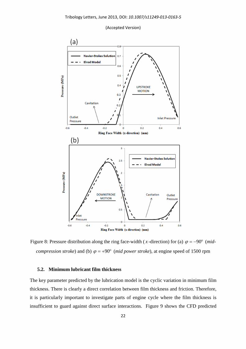
Figures 6-8 present the results for axial pressure profiles along the ring face-width at crank-
angles: °±1 , °± 21 and °±90 under assumed isothermal conditions. The predictions are
made by two different methods: (I) Two-phase flow Navier-Stokes equations and (II) the
Elrod’s modified approach to Reynolds equation. Good agreement is observed in all cases.
Note that the crank-angle of 0 corresponds to the position of TDC in transition from the
compression to the power stroke. The region bounded by the crank-angles 1± corresponds to
quite low speeds of entraining motion of the lubricant. Inlet reversals can be noted as the
piston sense of motion alters (Figure 6a and b). Figure 7b corresponds to the detonation point,
where the maximum combustion pressure occurs. The differences between the two methods
of analysis emerge in Figures 7a, and 8a and b. These correspond to relatively lightly loaded
contact conditions with higher speeds of entraining motion of the lubricant into the
conjunction. These differences are as the result of outlet boundary conditions, which are
clearly based on the film rupture point, beyond which cavitation region occurs. With the
Elrod’s approach there are prescribed contact outlet boundary conditions, which are based on
the value of film ratio 1ξ < . The CFD approach is based on open boundary condition (i.e.
there is no prescriptive outlet boundary condition for the lubricant film rupture location).
Since lightly loaded conditions with higher lubricant entraining velocity (in cases of
90ϕ = ± , mid-span piston position) lead to film rupture and cavitation any prescriptive outlet
conditions may be regarded as somewhat artificial. The difference is more significant in
terms of friction than pressure distribution (see later).

Tribology Letters, June 2013, DOI: 10.1007/s11249-013-0163-5
(Accepted Version)
20
Figure 6: Pressure distribution along the ring face-width (x-direction) for (a) °−= 1ϕ and (b)
,1°+=ϕ at engine speed of 1500 rpm

Tribology Letters, June 2013, DOI: 10.1007/s11249-013-0163-5
(Accepted Version)
21
Figure 7: Pressure distribution along the ring face-width ( x -direction) for (a) °−= 21ϕ
(compression stroke prior to TDC) and (b) °+= 21ϕ (detonation in power stroke), at engine
speed of 1500 rpm
Tribology Letters, June 2013, DOI: 10.1007/s11249-013-0163-5
(Accepted Version)
22
Figure 8: Pressure distribution along the ring face-width ( x -direction) for (a) °−= 90ϕ (mid-
compression stroke) and (b) °+= 90ϕ (mid power stroke), at engine speed of 1500 rpm
5.2. Minimum lubricant film thickness
The key parameter predicted by the lubrication model is the cyclic variation in minimum film
thickness. There is clearly a direct correlation between film thickness and friction. Therefore,
it is particularly important to investigate parts of engine cycle where the film thickness is
insufficient to guard against direct surface interactions. Figure 9 shows the CFD predicted

Tribology Letters, June 2013, DOI: 10.1007/s11249-013-0163-5
(Accepted Version)
23
minimum film thickness variation for the parabolic ring profile at the engine speed of 1500
rpm in comparison with that predicted by the Elrod’s model, both under assumed isothermal
conditions. The results of these analyses are quite close. Both solutions exhibit the expected
characteristic shape of the curve with instances of thin films occurring around the dead centre
reversals, where the lubricant entrainment velocity is negligible. Sufficient film thickness
exists at the mid-stroke positions, where there is adequate entrainment velocity. The thickness
of lubricant film is generally thinner during the power stroke owing to the higher gas loading
of the ring. The figure also includes the CFD predicted minimum film thickness variations for
thermal condition at the same engine speed. With thermal effects taken into account, the film
thickness is considerably reduced and the ring-bore conjunction resides in mixed or boundary
regimes of lubrication for a significant proportion of the engine cycle. This is a more realistic
result with regard to observed and measured friction, for instance by Furuhama and Sasaki
[38] and Gore et al [39]. Therefore, the significant differences between isothermal and
thermal analyses shown by Gosh and Gupta [40] is justified, but not often noted in much of
the reported studies.
Figure 9: Minimum film thickness at engine speeds of 1500 rpm
5.3. Prediction of Friction

Tribology Letters, June 2013, DOI: 10.1007/s11249-013-0163-5
(Accepted Version)
24
Piston-cylinder friction is a dominant source of parasitic mechanical losses in IC engines,
accounting for nearly 9% of the input fuel energy expended [41]. Therefore, one of the
overriding industrial objectives is to predict frictional losses from all the conjunctions of the
piston-cylinder system. Figure 10 shows the CFD predicted friction compared with the
experimental measurements by Furuhama and Sasaki [38] from a 2 cylinder rig made from an
8-cylinder Chevrolet engine running at the engine speed of 1200 rpm. The other predictions
in the figure are those by Mishra et al [12]. The CFD predictions conform well to the
experimental results and are an improvement upon those of Mishra et al [12] which are
isothermal and use Reynolds equation with Swift-Stieber exit boundary condition for the
hydrodynamic contribution. The agreement is particularly striking for the power stroke and
for the later stages of the compression stroke. There are some differences at mid-span in the
power stroke. There seems to be more boundary interactions in the experimental results. This
may well be because of bore out-of-roundness, thus some reduced clearance, which would be
expected of all cylinder bores in practice. However, such data is not provided in [38]. The
current analysis assumes a right circular cylindrical bore with circumferentially conforming
ring-bore contact.
Figure 10: Comparison of current work with experimental measurements for friction force
Tribology Letters, June 2013, DOI: 10.1007/s11249-013-0163-5
(Accepted Version)
25
Comparison of friction forces for isothermal and thermal cases is demonstrated in Figure 11.
Note that the isothermal analysis would be representative of cold steady state condition, for
example, similar to those at low engine speed emission tests defined by the NEDC (New
European Drive Cycle) [42], where the lubricant viscosity used in the analysis corresponds to
the temperature of 40○C. Various regions of predicted engine cycle frictional characteristics
are marked on the figure. Under isothermal (cold engine condition) viscous friction is
generally higher because of a higher lubricant viscosity. Furthermore, the dominant source of
viscous shear is Couette flow, which follows the piston sliding speed (second term in
equation (29)). The exception is the region in transition from compression to the power stroke
and extending past the detonation point. Under cold engine condition, it can be seen that the
pure proportionality v Uτ ∝ is lost in this region, because there is significant pressure loading
of the ring conjunction (combustion curves in Figure 5). In this region lubricant action is
dominated by Poiseuille shear (the first term in equation (29)).
The important point to note is that viscous friction, in general, is lower in the thermal case
due to reduced lubricant viscosity. However, at the dead centre reversals, because of low
entraining velocity the film thickness is significantly reduced (Figure 9), which leads to
boundary interactions in the case of thermal case. This can be representative of hot steady
state portion of the NEDC emission cycle [42]. The sharp rise rate in friction characteristics
at dead centre reversals, due to mixed or boundary regime of lubrication, are also marked on
Figure 11. In particular, the results show that friction at TDC reversal in transition from
compression to the power stroke corresponds to a significant proportional of all cyclic
frictional losses.

Tribology Letters, June 2013, DOI: 10.1007/s11249-013-0163-5
(Accepted Version)
26
Figure 11: Predicted friction under isothermal and thermal conditions with CFD and Elrod-
type analyses
5.4. Fluid properties and flow parameters changes along depth of film
Predictive methods based on Reynolds equation with appropriate boundary conditions, for
example that of Elrod [16] or Sawicki and Yu [36] determine lubricant film rupture and
reformation boundaries (Figure 1). The cavitation region is regarded to be contained within
the contact zone, where 1ξ < . However, as Reynolds equation assumes no pressure gradient
through the thickness of the lubricant film due to its thinness (i.e. dp/dz=0), there is no
prediction of disposition of the fluid phases. The use of Navier-Stokes equations with
Rayleigh-Plesset equation and analytical control-volume thermal model, described here,
enables the presence of fluid phases to be surmised according to void fraction as shown in
Figure 12, in this case at the engine speed of 6000 rpm and at crank angle of 90 . The choice
of these conditions is because at higher piston sliding velocity and relatively lighter contact
load a larger variation in fluid volume fraction results in the cavitation region as shown in
Figure 12. With the Reynolds-based approaches, there is no significant contribution to

Tribology Letters, June 2013, DOI: 10.1007/s11249-013-0163-5
(Accepted Version)
27
friction nor to the contact load carrying capacity as the cavitation region is assumed to remain
under atmospheric conditions. In the Navier-Stokes equations, there exists some contribution
due to the presence of a volume of liquid lubricant.
Figure 12: Changes of vapour volume fraction into the depth of the lubricant film at the crank
angle position 90 at the engine speed 6000 rpm (cavitation zone, mmx 2.0= )
Unlike other models, in the current CFD approach all operating and lubricant rheological
parameters alter with the depth of the lubricant film. The changes of lubricant properties and
flow parameters in the z direction (film depth) for crank angle 90 at engine speed 6000 rpm,
in high pressure zone (region of full film, mmx 1.0−= ) are plotted in Figures 13 and 14. The
parametric variations show that the flow of lubricant through the contact may be viewed as
layered streamlines at different rheological states. This means that in practice there would be
internal friction and load carrying capacity contained within the streamlined flow, which
would be more realistic than the idealised conditions belying Reynolds equation.

Tribology Letters, June 2013, DOI: 10.1007/s11249-013-0163-5
(Accepted Version)
28
Figure 13: The changes in lubricant viscosity (a) and density (b) into the depth of the
lubricant film at the crank angle of 90 and engine speed of 6000 rpm (full film region,
mmx 1.0−= )

Tribology Letters, June 2013, DOI: 10.1007/s11249-013-0163-5
(Accepted Version)
29
Figure 14: Changes in lubricant pressure (a) and temperature (b) in into the depth of the
lubricant film at the crank angle of 90 and engine speed of 6000 rpm (full film region,
mmx 1.0−= )
6. Conclusions
A new thermo-mixed hydrodynamic analysis method to study transient conditions in piston
compression ring-cylinder liner conjunction is presented. The method makes use of Navier-
Stokes equations, combined with Rayleigh-Plesset equation and analytical control-volume
thermal model. It also incorporates the Greenwood and Tripp method to take into account the

Tribology Letters, June 2013, DOI: 10.1007/s11249-013-0163-5
(Accepted Version)
30
effect of asperity interactions in the region of thin films. This approach has not hitherto been
reported in literature and highlights some important findings, when compared with the
traditional approaches, such as Elrod’s modification to Reynolds equation, based on the JFO
boundary conditions.
Firstly, the lubricant flow may be envisaged as streamlined flow with variable layered
potential energy contributing to load carrying capacity and internal friction. The layered
characteristic flow leads to regions with varied volume fraction of vapour in the cavitation
region of the contact. The exact disposition of vapour cavities in the form of bubbles and
their flow dynamics would constitute the use of Lagrange-Euler method for discrete phases in
the future extension of the current research.
Secondly, the results show that except at dead centre piston reversals, the underlying
mechanism for friction is through viscous shear of the lubricant. This implies that reduced
viscosity of the lubricant would be beneficial in reducing friction, if an alternative palliative
measure can be identified to reduce the effect of boundary friction at piston TDC reversal
particularly in transition from compression to power stroke. However, reducing lubricant
viscosity cannot be accommodated because the same engine oil flows through the higher load
intensity contacts such as the cam-follower pair, where high loads necessitate use of
lubricants which have sufficient load carrying capacity; i.e. high viscosity. Palliative action at
the TDC may be achieved through fabrication of surface textured reservoirs as shown by
Rahnejat et al [43] and Ryk and Etsion [44]. However, this action may lead to oil loss and
lubricant degradation in fully flooded parts of the engine cycle. The current analysis indicates
that in the lightly loaded parts of the engine cycle at high sliding speeds regions of cavitation
may occupy these intended textured reservoirs and reduce the load carrying capacity of the
contact. Further investigation of these effective micro-bearing would be required with the
approach expounded in the current analysis.
Acknowledgements
The authors would like to express their gratitude to the Lloyd’s Register Educational
Foundation (LREF) for the financial support extended to this research. Thanks are also due to
the Engineering and Physical Sciences Research Council (EPSRC) for the Encyclopaedic
Program Grant; some of research findings of which are used in this paper.

Tribology Letters, June 2013, DOI: 10.1007/s11249-013-0163-5
(Accepted Version)
31
References
[1] Gohar, R., and Rahnejat, H.: Fundamentals of Tribology. Imperial College Press (2008) [2] Andersson, B.S.: Company's Perspective in Vehicle Tribology-Volvo. Tribology Series (Elsevier), Vehicle Tribology 18, 503-506 (1991) [3] Richardson, D.E.: Review of power cylinder friction for diesel engines. Trans ASME, J. Trib. 122, 506-519 (2000) [4] Morris, N., Rahmani, R., Rahnejat, H., King P.D., Fitzsimons, B.: The influence of piston ring geometry and topography on friction. Proc. IMechE, Part J: J. Engng. trib. (2012), DOI: 10.1177/1350650112463534 [5] Rahmani, R., Theodossiades, S., Rahnejat, H., Fitzsimons B.: Transient elastohydrodynamic lubrication of rough new or worn piston compression ring conjunction with an out-of-round cylinder bore. Proc. IMechE, Part J: J. Engng. trib. 226, 284-305 (2012) [6] Ma, M. T., Sherrington, I., Smith, E. H.: Implementation of an Algorithm to Model the Starved Lubrication of a Piston Ring a Distorted Bores: Prediction of Oil flow and Onset of Gas Blow-by. Proc. IMechE, Part J: J. Engng. Trib. 210, 29-44 (1996) [7] Jeng, Y.: Theoretical Analysis of Piston Ring Lubrication-Part I: Fully Flooded Lubrication. Trib. Trans. 35, 696-706 (1992) [8] Jeng, Y.: Theoretical Analysis of Piston Ring Lubrication-Pan 11: Starved Lubrication and Its Application to a Complete Ring Pack. Trib. Trans. 35, 707-714 (1992) [9] Ma, M. T., Sherrington, I., Smith, E. H.: Analysis of lubrication and friction for a complete piston-ring pack with an improved oil availability model, Part I: Circumferentially uniform film. Proc. IMechE, Part J: J. Engng. Trib. 211, 1-15 (1997) [10] Akalin, O., Newaz, G.M.: Piston ring-cylinder bore friction modeling in mixed lubrication regime: Part II-Correlation with bench test data. Trans. ASME, J. Trib. 123, 219-223 (2001) [11] Mishra, P.C., Balakrishnan, S., Rahnejat, H.: Tribology of compression ring-to-cylinder contact at reversal. Proc. IMechE, Part J: J. Engng. Trib. 222, 815-826 (2008) [12] Mishra, P.C., Rahnejat, H. and King, P.D.: Tribology of the ring-bore conjunction subject to a mixed regime of lubrication. Proc. IMechE, Part C: J. Mech. Engng. Sci., 223, 987-998 (2009) [13] Bolander, N.W., Steenwyk, B.D., Sadeghi, F., Gerber, G.R.: Lubrication regime transitions at the piston ring-cylinder liner interface. Proc. IMechE. Part J: J. Engng. Trib. 219, 19–31 (2005) [14] Baker, C.E., Theodossiades, S., Rahnejat, H., Fitzsimons B.: Influence of in-plane dynamics of thin compression rings on friction in internal combustion engines. Trans. ASME, J. of Eng. for Gas Turbines & Power, 134, (2012), 092801 [15] Chong, W.W.F., Teodorescu, M., Vaughan N.D.: Cavitation induced starvation for piston-ring/liner tribological conjunction. Trib. Int., 44, 483-497 (2011) [16] Elrod, H. G.: A Cavitation Algorithm. Trans. ASME, J. Lubn. Tech., 103, 350-354 (1981) [17] Jakobsson, B., Floberg, L.: The Finite Journal Bearing Considering Vaporization. Trans. of Chalmers University of Tech., Gothenburg, Sweden, (1957)

Tribology Letters, June 2013, DOI: 10.1007/s11249-013-0163-5
(Accepted Version)
32
[18] Olsson, K. O.: Cavitation in dynamically loaded bearings. Trans. of Chalmers University of Technology, (1965) [19] Haddad, S. D., Tian, K.T.: An analytical study of offset piston and crankshaft designs and the effect of oil film on piston slap excitation in a diesel engine. Mechanism and Machine Theory, 30, 271–284 (1995) [20] Rahnejat, H.: Multi-body dynamics: vehicles, machines and mechanisms. Professional Engineering Publishing, Bury St Edmunds, UK: IMechE and Warrandale, PA, USA: SAE, joint publishers, (1998) [21] Bin Chik, A., Fessler, H.: Radial pressure exerted by piston rings. J. Strain Anal Eng. Des. I, 2, 165–171 (1966) [22] Felter, C. L.: Numerical simulation of piston ring lubrication. Trib. Int. 41, 914-919 (2008) [23] White F. M., "Viscous Fluid Flow", McGraw-Hill, 2nd Edition (1991) [24] Senocak, I., Shyy, W., Interfacial dynamics-based modelling of turbulent cavitating Flows, Part-1: Model development and steady-state computations. Int. J. Numer. Meth. Fluids 44, 975–995 (2004) [25] Singhal, A.K., Li, H.Y., Athavale M.M., Jiang Y.: Mathematical Basis and Validation of the Full Cavitation Model. ASME FEDSM'01, New Orleans, Louisiana, (2001) [26] Kubota, A., Kato, H., Yamaguchi H.: A new modelling of cavitating flows: a numerical study of unsteady cavitation on a hydrofoil section. J. Fluid Mech. 240, 59–96 (1992) [27] De la Cruz, M., Chong, W.W.F., Teodorescu, M., Theodossiades, S., Rahnejat, H.: Transient mixed thermo-elastohydrodynamic lubrication in multi-speed transmissions. Trib. Int. 49, 17-29 (2012) [28] Dowson, D., and Higginson, G. R.: A Numerical Solution to the Elasto-Hydrodynamic Problem. J. Mech. Eng. Sci. 1, 6-15 (1959) [29] Roelands, C. J. A.: Correlational Aspects of the Viscosity-Temperature-Pressure Relationship of Lubricating Oils. Ph.D thesis, Technical University Delft, Delft, The Netherlands (1966) [30] Houpert, L.: New results of traction force calculations in elasthydrodynamic contacts. J. Trib. – T. ASME 107, 241-248 (1985) [31] Lee, P.M., Stark, M.S., Wilkinson, J.J., Priest, M., Lindsay Smith, J.R., Taylor, R.I., Chung, S.: The degradation of lubricants in gasoline engines: Development of a test procedure to evaluate engine oil degradation and its consequences for rheology. Trib. Inter. Eng. Series 48, 593–602 (2005) [32] Olver, AV., Spikes, HA.: Prediction of traction in elastohydrodynamic lubrication. Proc IMechE, Part J: J. Eng. Trib. 212, 321–32 (1998) [33] Eyring, H.: Viscosity, plasticity and diffusion as examples of reaction rates. J Chem Phys. 4, 283–291 (1936) [34] Greenwood, J.A., Tripp, J.H.: The contact of two nominally flat rough surfaces. Proc IMechE 185, 625–634 (1970-1971) [35] Manninen, M., Taivassalo, V., Kallio, S.: On the mixture model for multiphase flow. VTT Publications 288 Technical Research Centre of Finland (1996) [36] Sawicki, J. T., Yu, B.: Analytical Solution of Piston Ring Lubrication Using Mass Conserving Cavitation Algorithm. Tribology Transactions 43, 587–594 (2000) [37] Snyder, D. O., Koutsavdis, E. K., Anttonen, J. S. R.: Transonic store separation using unstructured CFD with dynamic meshing". Technical Report AIAA-2003-3913, 33th AIAA Fluid Dynamics Conference and Exhibition, American Institute of Aeronautics and Astronautics (2003)

Tribology Letters, June 2013, DOI: 10.1007/s11249-013-0163-5
(Accepted Version)
33
[38] Furuhama S. and Sasaki S.: New device for the measurement of piston frictional forces in small engines. Society of Automotive Engineers, Pap. No. 831284 (1983) [39] Gore, M., Theaker, M., Howell-Smith, S., Rahnejat, H., King, P.D.: Direct measurement of piston friction of internal combustion engines using the floating liner principle. Proc. Instn. Mech. Engrs., Part D: J. Auto. Engng., in review process [40] Ghosh, MK., Gupta K.: Thermal effect in hydrodynamic lubrication of line contacts-piezoviscous effect neglected. Int. J. Mech. Sci. 40, 603–616 (1998) [41] Andersson, B.S., Company’s pespective in vehicle tribology. Leeds-Lion sympc. on Tribology, 503-506 (1991) [42] Chong, WWF., Teodorescu, M., Rahnejat, H.: Mixed thermo-elastohydrodynamic cam–tappet power loss in low-speed emission cycles. Int. J. Engine Res. (2012) doi: 10.1177/1468087412461631 [43] Rahnejat, H., Balakrishnan, S., King, P.D., Howell-Smith, S.: In-cylinder friction reduction using a surface finish optimization technique”, Proc. IMechE, Part D: J. Automobile Eng. 220, 1309-1318 (2006) [44] Ryk, G., Etsion, I.: Testing piston rings with partial laser surface texturing for friction reduction. Wear 261, 792-796 (2006)
Nomenclature
A apparent contact area
aA asperity contact area
b ring axial face-width
pC lubricant specific heat
d ring thickness
1E Young’s modulus of elasticity of the ring
2E Young’s modulus of elasticity of the liner
E ′ equivalent (reduced) modulus of elasticity
bf boundary friction
tf total friction
vf viscous friction
TF ring tension force
GF combustion gas force

Tribology Letters, June 2013, DOI: 10.1007/s11249-013-0163-5
(Accepted Version)
34
2/52 , FF statistical functions
g ring end gap
sg switch function
H enthalpy
h elastic film shape
mh minimum film thickness
sh ring axial profile
th heat transfer coefficient of boundary layer
I ring cross-sectional second area moment of inertia
k lubricant thermal conductivity
1sk thermal conductivity of the bore/liner
2sk thermal conductivity of the ring
l connecting rod length
L ring peripheral length
atmp atmospheric pressure
cp cavitation/lubricant vaporisation pressure
hp hydrodynamic pressure
gbp gas pressure acting behind the ring
1Q conductive heat flow rate through the liner
2Q conductive heat flow rate through the ring
cvQ convective heat flow rate
r crank-pin radius
0r nominal bore radius

Tribology Letters, June 2013, DOI: 10.1007/s11249-013-0163-5
(Accepted Version)
35
lR conductive thermal resistance for the lubricant layer
vR convective thermal resistance of the boundary layer (between film and surface)
Re Reynolds number
t time
U ring sliding velocity
21,UU surface velocities of contacting bodies
V
velocity vector
W contact load
aW load share of asperities
hW load carried by the lubricant film
cx oil film rupture point
Z pressure-viscosity index
Greek symbols
0α pressure/temperature–viscosity coefficient
β lubricant bulk modulus
ϕ crank angle
ζ number of asperity peaks per unit contact area
η lubricant dynamic viscosity
0η lubricant dynamic viscosity at atmospheric pressure
κ average asperity tip radius
λ Stribeck’s oil film parameter
µ pressure coefficient for boundary shear strength of asperities
1ν Poisson’s ratio of the ring material

Tribology Letters, June 2013, DOI: 10.1007/s11249-013-0163-5
(Accepted Version)
36
2ν Poisson’s ratio of the liner material
ρ lubricant density
0ρ lubricant density at atmospheric pressure
rσ liner surface roughness
lσ ring surface roughness
τ shear stress
0τ Eyring shear stress
Γ diffusion coefficient
θ temperature
eθ average (effective) lubricant temperature