development of a counter piston two stroke hcci engine542697/fulltext01.pdf · in this master...
TRANSCRIPT

Development of a counter piston two stroke HCCI engine
JOHN LARSSON
Master of Science Thesis Stockholm, Sweden 2009
Development of a counter piston two stroke HCCI engine
John Larsson
Master of Science Thesis MMK 2009:74 MFM125 KTH Industrial Engineering and Management
Machine Design SE-100 44 STOCKHOLM
Examensarbete MMK 2009:74 MFM125
Utveckling av en motkolvs tvåtaktsmotor med HCCI-förbränning
John Larsson
Godkänt
2009-12-18
Examinator
Hans-Erik Ångström
Handledare
Hans-Erik Ångström Uppdragsgivare
HCCI Technologies AB Kontaktperson
Hans-Erik Ångström
Sammanfattning Syftet med examensarbetet har varit den fortsatta utvecklingen mot en tvåtakts motkolvsmotor som fungerar med hjälp av HCCI-förbränning. Arbetet har haft två övergripande mål. Det första har varit att ta fram en stabil testplatform för motortester genom att förbereda en motorprovcell hos avdelningen för förbränningsmotorteknik på KTH. Det andra delmålet har varit att utnyttja denna testplatform för att utveckla en repeterbar, pålitlig och jämn tvåtaktsförbränning och sedan testa användandet av HCCI-drift. HCCI-förbränning är fördelaktigt då verkningsgraden är högre än för en ottomotor och utsläppen minskas i jämförelse med en diesel-motor. Nackdelen med användandet av HCCI är att processen är svårstyrd. Motorn som utvecklas i detta examensarbete är därför försedd med en patenterad mekanism för kompressionsreglering. Färdigställandet av testplatformen, dvs motorprovcellen, blev klart inom rimlig tid. Dock så har felande motorkomponenter orsakat upprepade avbrott i motorutvecklingen vilket har resulterat i fördröjningar och forcerat ett flertal ändringar i planeringen. Stabil tvåtaktsförbränning uppnåddes ett flertal gånger men då komponenter ständigt gick sönder och krävt reparation eller utbyte till en förbättrad komponent kunde förhållandena knappast kallas repeterbara. Värdefulla resultat som erhållits har istället varit en högre grad av förståelse för vad denna motor kräver i områdena smörjning, laveransgrad av luft, tändsystem och utformning av avgassytemet. Motorn har körts med HCCI-förbränning några gånger. Dock har förbränningen då aldrig varit stabil eller effektiv nog att köras utan yttre krafttillförsel.

Master of Science Thesis MMK 2009:74 MFM125
Development of a counter piston two stroke HCCI engine
John Larsson
Approved
2009-12-18 Examiner
Hans-Erik Ångström Supervisor
Hans-Erik Ångström Commissioner
HCCI Technologies AB Contact person
Hans-Erik Ångström
Abstract The purpose of this thesis has been the continued development towards HCCI combustion in a two-stroke counter piston engine. There have been two main goals of the thesis work. The first was to create a stable platform for engine tests by preparing an engine test cell in the department for combustion engines at KTH. The second goal was using that platform to develop reliable and repeatable two-stroke combustion and then test the use of HCCI combustion. The advantages of using HCCI combustion are that the efficiency is higher than in a SI engine and the emissions are lower than in a corresponding diesel engine. The problem is that the combustion process is hard to regulate. The engine that is developed in this thesis work is therefore fitted with a patented mechanism for compression regulation. The completion of the testing platform, i.e. the engine test cell, was finished in a reasonable time span. However, usage of inadequate engine components resulted in reoccurring engine breakdowns that caused delays and several changes in the test planning. Reliable two-stroke combustion was achieved several times but due to the constant breakdowns that required repairs or even a change to a better component the conditions could hardly be called repeatable. Valuable results that have been achieved has instead been a higher degree of understanding of what this engine requires in areas such as lubrication, scavenging, ignition and design of the exhaust system. The engine has been run with HCCI combustion a couple of times, yet the combustion process has never been stable or effective enough to be run without the addition of an outside power supply.

Acknowledgements I would first like to thank my supervisor Hans-Erik Ångström for presenting me with a master thesis project with such variety of challenging and interesting tasks. There was never a dull moment and I feel lucky to have had the opportunity to have worked with him and this engine. For continued support and interest I would also like to thank HCCI Technologies AB specifically Göran Linder and Tom Whitlock. I would also like to thank the technician Bengt Aronsson for all the time he put into helping us with the engine. The same goes for all the other technicians who have helped along the way; Tommy Tillman, Patric Hellgren, Jack Ivarsson and Ulf Andorff. Without you all, progress would have been very slow indeed. Thanks also to Niklas Winkler for helping us with exhaust pipe dimension calculations and to all the other people at the division of internal combustion engines for the advice you have provided. For providing me with valuable comments while writing this report and for continued support, thank you Rafael Villasmil. I wish you success in the continued development of this engine. Last but not least, for being such a good work mate and the fruitful collaboration, thank you Kim Jaktlund.

1
Contents 1. Introduction 3 2. The test cell 4
2.1. Overview 42.2. Signal processing 52.3. Computer logging 72.4. Electronic connections 82.5. Standalone cables 9
3. The engine 10
3.1. Engine build 103.1.1. Engine internals 103.1.2. External components 11
3.2. Sensors 143.2.1. Motion 143.2.2. Temperature 153.2.3. Pressure 163.2.4. Other measurement devices 16
3.3. Handling of the engine 183.3.1. Safety precautions 183.3.2. Startup procedure 183.3.3. Maintenance 19
4. Engine modifications and tests 20
4.1. Lubrication 204.2. Working point efficiency 204.3. Ignition charge time 204.4. Exhaust pipe 214.5. HCCI 214.6. Scavenging pump 21
5. Results 22
5.1. Lubrication 225.2. Working point efficiency 225.3. Ignition charge time 245.4. Exhaust pipe 305.5. HCCI 305.6. Scavenging pump 32
2
6. Discussion 33 7. Conclusions 33 8. Recommendations and future work 34 References 35 Appendix 1: Disassembly manual 36 Appendix 2: Assembly manual 47 Appendix 3: Calibration of Heidenhein sensor 60 Appendix 4: Projektplanering examensarbete 62

3
1. Introduction HCCI is short for Homogenous Charge Compression Ignition. What this means is that in the HCCI process, the fuel is injected around the bottom dead centre (BDC) and is mixed with the air to a homogenous mixture, like in an Otto engine, and that this mixture is then ignited by compression heat, like in a diesel engine. There are many advantages in using HCCI combustion. The efficiency is theoretically close to that of a diesel engine while many of the emission problems are avoided. Due to a fast combustion with comparatively low temperature, the amount of NOx produced is significantly lower. A homogenous air-fuel mix means that there are no rich zones which mean that the creation of soot is kept to a minimum. The only emissions from this combustion type in any real quantity are HC and CO which can both be oxidized in a catalytic converter and of course also CO2. The CO2 emissions are also lowered due to the increase in engine efficiency. Another advantage is that unlike the Otto engine, the process can function at high lambda. The effect of this is that the combustion temperature is lowered which results in a decrease of heat losses from the engine. The problem of using HCCI combustion is that it is hard to control. A diesel engine uses the time of injection and the Otto engine uses the spark timing to adjust when combustion take place but the HCCI engine can do nothing of this. Instead a compression regulation mechanism can be used. In this master thesis work a two-stroke counter piston engine fitted with a patented compression regulation mechanism is used. The purpose of the work done is to further the development of this engine and to test the functionality of this mechanism.

4
2. The test cell
The engine is attached to a mobile test bench together with a hydrostatic breaking system. This bench is put in the support room for engine test cell 3 in the KTH combustion engineering department. This section will give a broad overview of the functions used in the test cell as well as a more detailed description of some of those. A complete map of the electrics and sensor systems will also be presented.
2.1 Overview When put in the cell, the test bench utilize some of the resources available inside the test cell. It is also connected to various logging computers that also have the ability to change parameters in for example, the ECU. Figure 1 shows a diagram of the various connections inside the cell.
Figure 1: Overview of the connections inside the cell In the cell there is a water supply (blue lines Figure 1) that is used to cool two heat changers. These in turn cool the engine cooling water and the oil used in the hydrostatic brake. Electricity to ECU and other engine components is taken from cell batteries outside the cell and an electric cabinet inside the cell (red lines Figure 1). A lot of sensors are mounted on and around the engine and its accessories. Signals from these are sent from their respective sources to the cell connections box where they are
5
translated or amplified and then sent on to the logging computers outside the cell (green lines Figure 1).
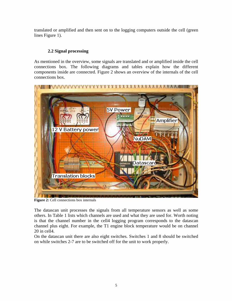
2.2 Signal processing As mentioned in the overview, some signals are translated and or amplified inside the cell connections box. The following diagrams and tables explain how the different components inside are connected. Figure 2 shows an overview of the internals of the cell connections box.
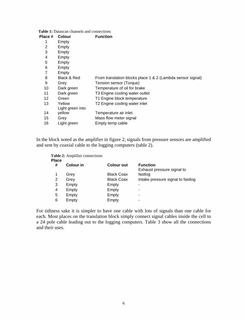
Figure 2: Cell connections box internals The datascan unit processes the signals from all temperature sensors as well as some others. In Table 1 lists which channels are used and what they are used for. Worth noting is that the channel number in the cell4 logging program corresponds to the datascan channel plus eight. For example, the T1 engine block temperature would be on channel 20 in cell4. On the datascan unit there are also eight switches. Switches 1 and 8 should be switched on while switches 2-7 are to be switched off for the unit to work properly.
6
Table 1: Datascan channels and connections Place # Colour Function
1 Empty 2 Empty 3 Empty 4 Empty 5 Empty 6 Empty 7 Empty 8 Black & Red From translation blocks place 1 & 2 (Lambda sensor signal)9 Grey Tension sensor (Torque)
10 Dark green Temperature of oil for brake 11 Dark green T3 Engine cooling water outlet 12 Green T1 Engine block temperature 13 Yellow T2 Engine cooling water inlet
14 Light green into yellow Temperature air inlet
15 Grey Mass flow meter signal 16 Light green Empty temp cable
In the block noted as the amplifier in figure 2, signals from pressure sensors are amplified and sent by coaxial cable to the logging computers (table 2).
Table 2: Amplifier connections Place
# Colour in Colour out Function
1 Grey Black Coax Exhaust pressure signal to fastlog
2 Grey Black Coax Intake pressure signal to fastlog 3 Empty Empty - 4 Empty Empty - 5 Empty Empty - 6 Empty Empty -
For tidiness sake it is simpler to have one cable with lots of signals than one cable for each. Most places on the translation block simply connect signal cables inside the cell to a 24 pole cable leading out to the logging computers. Table 3 show all the connections and their uses.

7
Table 3: Translation blocks Place # Colour in Colour out Function
1 Black Dotted white/blue Datascan Ch8 (Lambda sensor signal) 2 Red Dotted blue/black Datascan Ch8 (Lambda sensor signal) 3 Light blue Blue Relay power to starting motor 4 Yellow Yellow Hall sensor signal from ecu box 5 Red Red Hall sensor signal from ecu box 6 Black Orange Relay power to fuel pump 7 Green Green Signal from brake speed sensor
8 Black Black into metallic?
Brake regulator signal from Cell4 to regulation box
9 Empty Yellow/green - 10 Blue Black (2) 12V from power cabinet to electronic scale 11 Empty Black (1) -
2.3 Computer logging There are two computers in contact with the cell. One is a stationary computer and has the Cell4 program and the other is a laptop with the ecoCtrl program. There is also another laptop whose only function is to show picture from a web-cam mounted inside the cell.
• Cell4 Cell4 is a cell control program developed in house by Professor Hans-Erik Ångström. It is used to present and log signal output from inside the cell and also to switch relays inside the cell on and off. Figure 3 shows the main window of the cell4 program.
Figure 3: Main window of the ‘cell4’ program

8
• ecoCtrl
The program ecoCtrl (also made by Professor Hans-Erik Ångström) is connected only to the ecu box of the engine. It can present and log signals and it can also change the parameters inside the ecu. Figure 4 show the window in ecoCtrl where the engine parameters that can be changed. For more detailed information about this program see the master thesis report made by David Larsson [1].
Figure 4: Engine parameters window in the program ‘ecoCtrl’
2.4 Electric connections Electricity for sensor systems and also for the engine ecu is taken from the cell's 12 V batteries. 5V, 24V and also in some cases 12V currents are taken from an electricity cabinet.
9
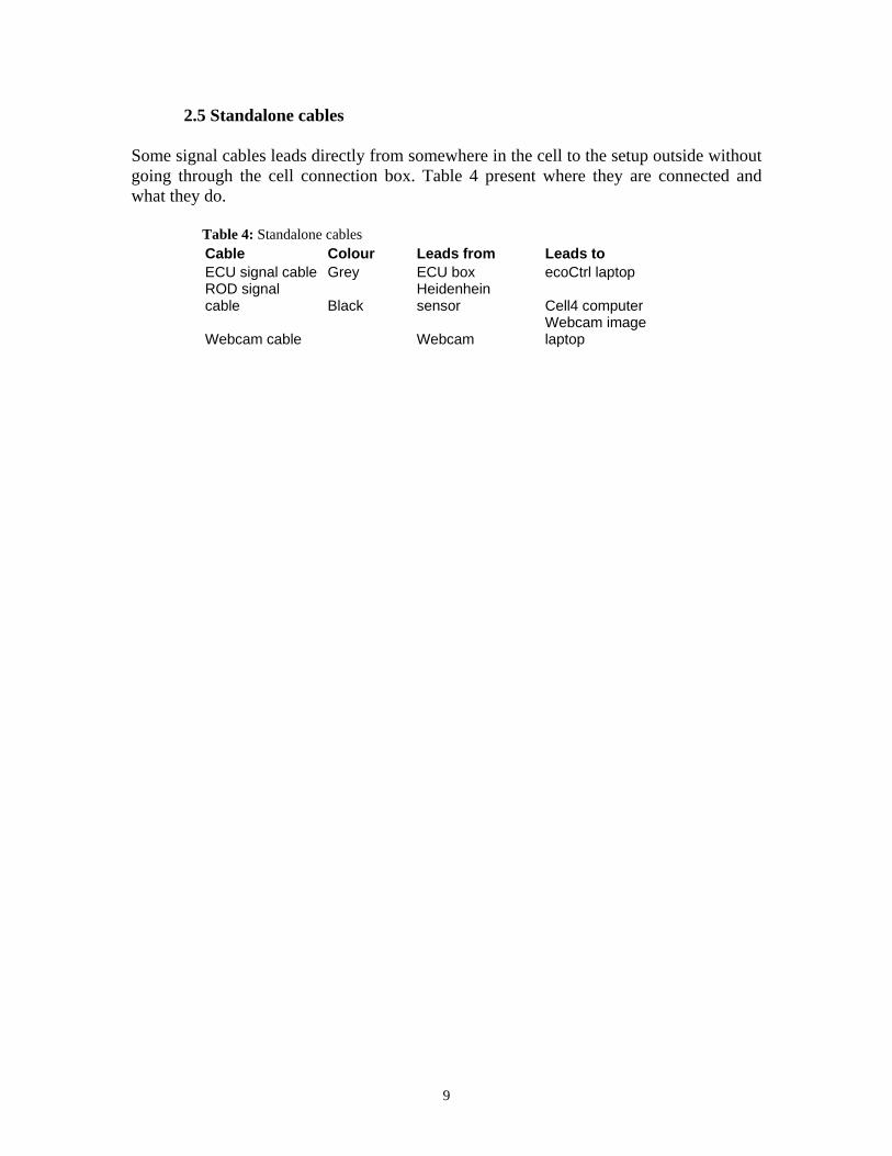
2.5 Standalone cables Some signal cables leads directly from somewhere in the cell to the setup outside without going through the cell connection box. Table 4 present where they are connected and what they do. Table 4: Standalone cables Cable Colour Leads from Leads to
ECU signal cable Grey ECU box ecoCtrl laptop ROD signal cable Black
Heidenhein sensor Cell4 computer
Webcam cable Webcam Webcam image laptop

10
3. The engine The engine used in this project is a counter piston, 2-stroke, single cylinder with a displacement around 50 cc. This is a scaled down version of the Junkers Jumo 205 engine used in the Second World War. For experimental purposes, it is externally scavenged and since it is a direct injection engine it also has an external oil pump. To be able to regulate HCCI combustion the engine has been fitted with a patented system that uses the ability to change the phase difference between the crankshafts to adjust the compression ratio.
3.1. Engine build While the internals of the engine has remained the same throughout the master thesis work, the surrounding parts have been changed and improved upon a lot to get them to work. The following sections will describe in detail the components in and around the engine.
3.1.1. Engine internals Cylinders and pistons are custom designed at KTH. They are cast in aluminium and the cylinder bore is also coated with nickasil. The crankshafts and piston rods are taken from Husqvarna 25 cc engines (326 7HVXS.0254 EP TWC). Four ball bearings exist in the engine and these are high temperature resistant ones from SKF, model nr 6201-2RSH. Figure 5 shows an exploded view of the engine internals.
Figure 5: Exploded view of the cylinder and one side of the engine internals

11
3.1.2. External components For the engine to work, a lot of additional components are needed. These are described in the following sections.
• Regulation mechanism To be able to regulate when HCCI combustion takes place, a compression regulation mechanism is used. It uses the fact that there are two crankshafts that can be made to spin either completely synchronized or with a chosen phase difference. Depending on what phase difference there is, the volume when the pistons meet will change. The larger the phase difference the larger the volume and therefore the smaller the compression ratio. There is also a second effect of changing the phase difference. As the phase increases, the exhaust piston will begin to move ahead of the intake piston. As the pistons control the opening and closing of the ports, this will mean that the exhaust port opens and closes before the intake port. This result in better scavenging and also a decrease in the amount of air washed through the cylinder. The mechanism consists of four gearwheels, two arms and a linear actuator as shown in figure 6. Gearwheel number 1 and 4 are attached to the intake and the exhaust crankshafts respectively while the two middle wheels are mounted to the arms and can therefore be moved. As the linear actuator extends or retracts, the middle wheels will follow the arms. This results in an increase or a decrease in phase difference between the crankshaft rotations.
Figure 6: Phase adjustment mechanism
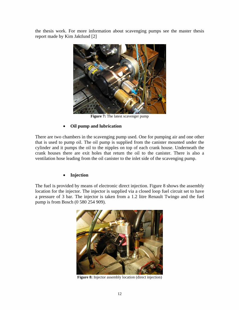
• Scavenging pump
To be able to change the amount of air fed to the engine an external scavenging pump is used and not the crank cases as in a normal 2-stroke engine. Figure 7 show the pump in use as this report is written but this is an area where a lot of change has occurred during
12
the thesis work. For more information about scavenging pumps see the master thesis report made by Kim Jaktlund [2]
Figure 7: The latest scavenger pump
• Oil pump and lubrication
There are two chambers in the scavenging pump used. One for pumping air and one other that is used to pump oil. The oil pump is supplied from the canister mounted under the cylinder and it pumps the oil to the nipples on top of each crank house. Underneath the crank houses there are exit holes that return the oil to the canister. There is also a ventilation hose leading from the oil canister to the inlet side of the scavenging pump.
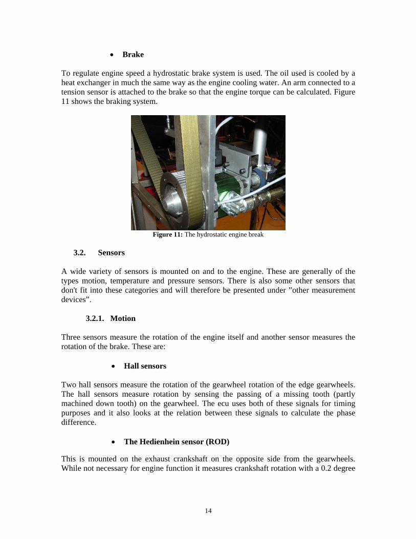
• Injection The fuel is provided by means of electronic direct injection. Figure 8 shows the assembly location for the injector. The injector is supplied via a closed loop fuel circuit set to have a pressure of 3 bar. The injector is taken from a 1.2 litre Renault Twingo and the fuel pump is from Bosch (0 580 254 909).
Figure 8: Injector assembly location (direct injection)

13
• Ignition
The HCCI combustion is hard to achieve when the engine is cold. To heat the engine it is run on normal spark ignition which requires the engine to have an ignition system. The spark plug used is model from NGK called ME-2 and is normally used for model engines (figure 9). The ignition coil is from Biltema.
Figure 9: The spark plug used
• Cooling
The cylinder is water cooled by a simple system consisting of a water pump and a heat changer. The heat changer uses cold water from the cell to evacuate the heat. The water pump speed is regulated linearly as a function of cylinder block temperature. Figure 10 shows the heat changer and the hoses connected to it.
Figure 10: Heat changer and connected hoses
14
• Brake To regulate engine speed a hydrostatic brake system is used. The oil used is cooled by a heat exchanger in much the same way as the engine cooling water. An arm connected to a tension sensor is attached to the brake so that the engine torque can be calculated. Figure 11 shows the braking system.
Figure 11: The hydrostatic engine break
3.2. Sensors
A wide variety of sensors is mounted on and to the engine. These are generally of the types motion, temperature and pressure sensors. There is also some other sensors that don't fit into these categories and will therefore be presented under ”other measurement devices”.
3.2.1. Motion Three sensors measure the rotation of the engine itself and another sensor measures the rotation of the brake. These are:
• Hall sensors Two hall sensors measure the rotation of the gearwheel rotation of the edge gearwheels. The hall sensors measure rotation by sensing the passing of a missing tooth (partly machined down tooth) on the gearwheel. The ecu uses both of these signals for timing purposes and it also looks at the relation between these signals to calculate the phase difference.
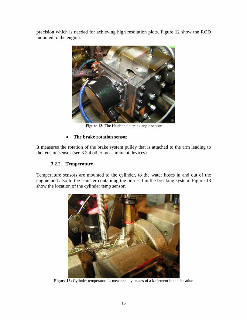
• The Hedienhein sensor (ROD) This is mounted on the exhaust crankshaft on the opposite side from the gearwheels. While not necessary for engine function it measures crankshaft rotation with a 0.2 degree
15
precision which is needed for achieving high resolution plots. Figure 12 show the ROD mounted to the engine.
Figure 12: The Heidenhein crank angle sensor
• The brake rotation sensor
It measures the rotation of the brake system pulley that is attached to the arm leading to the tension sensor (see 3.2.4 other measurement devices).
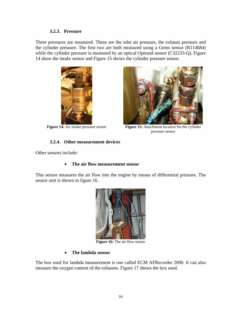
3.2.2. Temperature Temperature sensors are mounted to the cylinder, to the water hoses in and out of the engine and also to the canister containing the oil used in the breaking system. Figure 13 show the location of the cylinder temp sensor.
Figure 13: Cylinder temperature is measured by means of a k-element in this location
16
3.2.3. Pressure Three pressures are measured. These are the inlet air pressure, the exhaust pressure and the cylinder pressure. The first two are both measured using a Gems sensor (R114684) while the cylinder pressure is measured by an optical Optrand sensor (C32233-Q). Figure 14 show the intake sensor and Figure 15 shows the cylinder pressure sensor.
Figure 14: Air intake pressure sensor
Figure 15: Attachment location for the cylinder
pressure sensor
3.2.4. Other measurement devices Other sensors include:
• The air flow measurement sensor
This sensor measures the air flow into the engine by means of differential pressure. The sensor unit is shown in figure 16.
Figure 16: The air flow sensor
• The lambda sensor
The box used for lambda measurement is one called ECM AFRecorder 2000. It can also measure the oxygen content of the exhausts. Figure 17 shows the box used.

17
Figure 17: Lambda and oxygen content measurement unit
• The exhaust values measurement unit
This is measured by a collection of measurement devices from BOO Instrument AB. The values measured are CO, HC, CO2, NOx and O2. The implementation of this unit was very late in the thesis work and there are therefore no tests that have used it presented in this report.
• Tension sensor The tension sensor is attached to the end of a beam that is mounted to the hydrostatic brake. The output signal can therefore be translated into engine torque. Figure 18 shows the end of the moment arm and the tension sensor.
Figure 18: The tension sensor attached to the moment arm
18
3.3. Handling of the engine As the engine and parts around it have been designed for specific functionality and not safety or easy handling there is some things that an engineer new to the engine and cell environment needs to know. These things are the safety precautions when working in and near the cell, the procedure followed when starting the engine from cold and finally how to service the engine should it prove necessary.
3.3.1. Safety precautions There are some things that need to be taken into consideration before work is done to the engine or before a start-up. These are:
• Wear clothes that can take a little oil, preferably a working coat or similar. The environment around the engine is less than clean.
• Use earplugs or some other kind of hearing protection as there can be a lot of noise in the basement even without any engine running.
• Be sure to unplug the power cable leading to the electric motor before touching the engine for any reason.
• Keep the door to the cell closed when running the engine. An open door causes the ventilation system in all four cells to fail.
3.3.2. Start-up procedure Before being able to run the engine, some steps need to be taken. For the cell to be running at all the following needs to be done:
1. Make sure the oil canister is filled and that there is water in the cooling system. 2. Start the cell above the support room used by the HCCI engine. Do this by turning
the key next to the emergency button. Make sure no one is working in the cell before doing this. If a clicking sound isn't heard, an emergency button is most likely still pushed in.
3. Also in the cell above, load up a config file in cell4 that has an option for opening the exhaust shutters and make sure this option is turned on (showing a 1).
4. Start the support room in the same way as the cell above. 5. Start the three computers, i.e. the cell4 stationary computer, the ecoCtrl laptop and
the web-cam laptop. 6. Switch on the bench electricity. 7. Start ecoCtrl and make sure there is a connection (some lamps should be
flashing). 8. Start cell4 and load up the latest (or appropriate) config file. 9. Start the web-cam program and make sure that the camera is aligned.
19
Now the engine can be turned on from the cell4 computer. If this is the first run of the day or if the engine has been worked on for any reason the following steps should be taken to avoid mechanical damage:
1. Check if anything is in the way of any moving parts on the engine and the test bench (gearwheels, brake etc.). Also check that no cables are lying on any parts that will become hot (cylinder, exhaust pipe).
2. Drag the engine by switching on the start motor only. Keep a close eye on the webcam image.
3. While the engine is being dragged, change the phase difference to 0 (or something like 0.5, Ctrl + P in ecoCtrl) and take a fastlog in cell4.
4. Stop the engine and take a look at the fastlog in Mkpad4. Bring up the cylinder pressure curve and check if it peaks on a yellow line. If not the ROD sensor needs to be recalibrated (see 3.3.3.3. Calibration). Also check if the maximum pressure is logical, that is around 40 bar or a little lower. Lower pressure then that indicates that something is wrong with the piston rings or something similar.
5. Go into the cell and see if everything is as it should, that nothing has loosen due to vibrations and that the gearwheels still spin freely.
6. Start-up procedure complete. Start the engine by switching on both the start motor and the fuel pump.
3.3.3. Maintenance
This section is covered by the assembly, disassembly and calibration manuals. These can be found in appendix 1, 2 and 3.
20
4. Engine modifications and tests There was a general plan outlined in the beginning of the master thesis work but that plan has had to be remade time and time again due to several breakdowns and problems caused by at that time unknown factors. Often these problems couldn't be solved by simply renovating of the engine but have instead required a major change like the changing of a vital component. This unreliability of the engine's functionality has forced the abandonment of a lot of the planned test and has given ground for new ones. Only in the very end did the engine work as expected every time it was started. The topics presented in this section do not, because of the mentioned problems, always follow a strict time-line. Instead they are presented roughly in the order of when a problem surfaced. The solution to some problems has sometimes not presented itself until late in the thesis work, after some other problem had been solved.
4.1. Lubrication Many breakdowns of the engine have been due to loss of compression because the piston rings have stuck in their grooves and this lead to the belief that the current oil pump was not sufficient to deliver enough lubrication to the engine. Tests were performed to see if a 2 % mix of 2-stroke oil mixed into the fuel would be sufficient. Late in the thesis work a new scavenging pump was found that could also be used as an oil pump. Tests have also been conducted with that pump instead of the old and by also removing the oil mixed fuel.
4.2. Working point efficiency When the engine was first put together port injection was used. A series of test with varying lambda (varying amounts of fuel injected) and different engine speeds was performed in an attempt to get the highest efficiency possible. The same tests was then performed but with direct injection.
4.3. Ignition charge time As the engine use a very small spark plug while having an ignition coil size normal for a car, it becomes important to know exactly how long the charge time should be. On several occasions when using a long charge time the spark has jumped prematurely between the spark plug and the cylinder. Therefore, tests were conducted where the results of a range of charge times was investigated. The tests were performed as follows:
1. Time of charge start set as a variable ranging between 40 and 120 degrees (0,33 to 2,67 ms) before TDC (Top Dead Centre)
2. Time of ignition set to 30 degrees before TDC
21
3. Injection angle was set to 110 degrees after TDC 4. Starter motor and fuel pump was turned on 5. Injection duration was fine tuned to get the engine to work as evenly as possible 6. Engine speed limited to 5000 rpm 7. Temperature kept at a preset constant value (around 92˚C) 8. A fastlog in cell4 was taken
4.4. Exhaust pipe
A vital component of a two-stroke engine has always been the design of the exhaust pipe in order to prevent losses from blow-through. Until the work began on a new custom made pipe for this engine, a straight pipe that was connected to another straight pipe of larger dimensions was used. This, according to fluid dynamics, creates a suction pulse that bounces back and is therefore even more detrimental to the gas flow through the engine than one pipe ending in open air would be. Also, since all exhaust pipes in all the cells are connected to a ventilation system that sucks away all exhaust gases the effect is made worse. It was decided that an exhaust pipe that was designed as a normal two stroke exhaust pipe was needed to counter these problems. After the exhaust pipe was manufactured, testing was performed to see if there had been some improvement. The way this test was planned was that engine parameters were to be copied from an earlier functional run of the engine. The results were then to be compared with the results from the old run too see if there was some efficiency gained.
4.5. HCCI Some testing to get the engine to run without a spark plug has been conducted. Tests in this area have not been extensive as a lot of basic components of the engine have had to be improved upon beforehand. Therefore the testing procedure has been more or less to simply switch off the spark plug and then see if the engine is still running.
4.6. Scavenging pump The work with the scavenging pump will be covered in detail in the master thesis report made by Kim Jaktlund [2]. Suffice to mention that a large factor in the functionality of the engine has been this pump. A lot of time has been spent looking for a replacement to the original pump used and even more in the work of adapting the new pumps found to the engine.

22
5. Results As mentioned in chapter 4: 'engine modifications and tests', the results presented do not follow a strict time-line.
5.1. Lubrication The first sign of improvement was seen when the oil used was changed to low smoke oil from Husqvarna. When the use of a 2 % oil mix in the engine was introduced the problems described earlier stopped. No more piston rings got stuck due to carbon buildup. At this time there was no exhaust gas measurement other than pressure so the impact on the amount of residual gases has not been examined. The use of the new external oil pump indicates that it can replace both the old one and the oil mixed into the fuel. As it is more powerful by far it is almost too effective in delivering oil which sometimes result in a leakage of oil in some places. As this was more a problem of inconvenience (oil refill needed quite often) than something that could cause breakdowns, it was left to be solved at a later date.
5.2. Working point efficiency The idea was to compare the efficiency at different load points, only poor repeatability and several engine breakdowns caused this to fail and it was hard to find many points where the engine worked at all. The tests with port injection failed quickly. On the first test the engine worked quite well but the functionality of the engine deteriorated quickly as further tests were performed. After deciding on a complete engine renovation it was discovered that the intake piston rings had stuck in their grooves causing loss in compression and that the intake was mostly filled with fuel which was reasoned to be because of wall-wetting from the injection spray. When using direct injection the problem described above was avoided, however the fuel spray still hit the opposite wall inside the cylinder. As the fuel didn't have as long a time to mix with the air it is thought that when cold, the scavenging would just carry the fuel out of the engine. Cylinder pressure curves from running the engine show no combustion or at best a late combustion. An indication of this conclusion being true comes from looking at the spark plug after a cold run. It is then usually coated with soot or wet from fuel. Figure 19 shows a case where, when cold, there is a slight bulge in pressure at the end of the compression part of the stroke.

23
Figure 19: Cylinder pressure curve of an example of late combustion The heat release diagram for the same cycle is shown I figure 20. It is clear from this figure that there is some combustion late in the cycle.
Figure 20: Heat release from a cycle with late combustion
-5
0
5
10
15
20
25
30
-100 -75 -50 -25 0 25 50 75 100 125 150
Crank angle [deg]
Cyl
inde
r pr
essu
re [b
ar]
-2
-1
0
1
2
3
4
5
-25 -5 15 35 55 75 95 115
Crank angle [deg]
Hea
t rel
ease
dQ
/deg
[J]

24
5.3. Ignition charge time Graphs of the results from this test will be presented in ascending order of charge duration. For ease of reading table 5 will be presented again. Table 5: Charge and injection timings
Figure 21 shows the results from the first test using charge duration of 10 CA degrees (0,33 ms). Although fuel injection is on no combustion takes place as the spark is too weak to ignite the air-fuel mix. Worth noting is that if the engine was left to run there would after a while be HCCI combustion. More will be presented about that later in this report.
-10
0
10
20
30
40
50
-100 -75 -50 -25 0 25 50 75 100
Crank angle [deg]
P cyl_barign puls_volt
Figure 21: Cylinder pressure and ignition voltage at 10 degree (0,33) charge duration Next 20 degree (0,66 ms) charge duration was tested. In figure 22 the results are presented in the same way as before. By using an injection duration of 1,4 ms combustion has been achieved though it is very uneven. The pressure curve shown is one of the rare ones that actually have combustion that looks like it’s supposed to. A resemblance of combustion occurs on average in every fifth cycle and the process barely keeps the engine running on its own power. Sudden stops were frequent. Noteworthy is that the ignition pulse is now split up between a pulse at 30 degrees before TDC and another at around 15 degrees later and also that the initial pulse is a little bit lower in current than before. Not seen in figure 22 is that each time no combustion occurs the voltage of the initial pulse is notably higher but there is still a second pulse.

25
Figure 22: Cylinder pressure and ignition voltage at 20 degree (0,66 ms) charge duration Figure 23 shows the results from using 30 degree (1 ms) charge duration. Combined with a slightly lowered injection duration of around 1,3 ms the combustion now occurs more frequently but it is still struggling to run on its own power for any longer periods. There is still a double pulse and this will always be the case as the charge duration increases. What's more, as is somewhat visible when comparing Figure 22 and Figure 23 is that the gap between the first and second pulse has slightly increased.
Figure 23: Cylinder pressure and ignition voltage at 30 degree (1 ms) charge duration
-10
0
10
20
30
40
50
60
70
-100 -75 -50 -25 0 25 50 75 100
Crank angle [deg]
P cyl_bar
ign puls_volt
-10
0
10
20
30
40
50
60
-100 -75 -50 -25 0 25 50 75 100
Crank angle [deg]
P cyl_bar
ign puls_volt

26
At 40 degree (1,33 ms) charge duration and an unchanged injection duration (1,3 ms) the combustion looks a bit like the one in a four stroke engine i.e. it takes place every other cycle. Figure 24 shows an example of such combustion. The increase in gap between the two pulses is now even more apparent, as is the slightly higher initial pulse. The engine at this point has no trouble powering itself and no sudden engine stops occur.
Figure 24: Cylinder pressure and ignition voltage at 40 degree (1,33 ms) charge duration With charge duration of 50 degrees (or 1,66 ms), the combustion process is stable. Combustion occurs on almost every cycle and the engine has no trouble powering itself as well as some braking force. The process also tolerates a leaner air-fuel mix as the injection duration now can be lowered to 0,9 ms. As before, the initial pulse is higher and the gap between the two pulses is even wider. Figure 25 shows the results of using 50 degree (1,66 ms) charge duration.
-10
0
10
20
30
40
50
60
70
-100 -75 -50 -25 0 25 50 75 100
Crank angle [deg]
P cyl_bar
ign puls_volt

27
Figure 25: Cylinder pressure and ignition voltage at 50 degree (1,66 ms) charge duration The graphs from the tests where the charge duration was increased further (60, 70 and 90 CA degrees or 2, 2,33 and 3 ms) showed no improvement in functionality of the engine. The injection duration could be lowered to 0,8 ms and the engine would still work, only it would then no longer deliver as much power. The only visible difference is that the gap between the pulses has widened even further. Figure 26 shows the most extreme case when using 90 degrees (3 ms) of charge time. In the figure the second spark occurs almost at the peak pressure. This together with the fact that the combustion always takes place at around the same crank angle, in this case and the ones before, seems to indicate that the second pulse have no impact on the combustion process.
-10
0
10
20
30
40
50
60
70
80
-100 -75 -50 -25 0 25 50 75 100
Crank angle [deg]
P cyl_barign puls_volt

28
-10
0
10
20
30
40
50
60
70
80
-100 -75 -50 -25 0 25 50 75 100
Crank angle [deg]
P cyl_bar
ign puls_volt
Figure 26: Cylinder pressure and ignition voltage at 90 degree (3 ms) charge duration To further illustrate that the second pulse has no impact on combustion timing, see figure 27. It illustrates the average pressure curves over 40 cycles for 50 and 90 degree (1,67 and 3 ms) charge times.
Figure 27: Average pressure curves for 50 and 90 degrees (1,67 and 3 ms) of charge time Finally, after deciding that 60 degree (2 ms) charge duration would be the best and also some fine tuning of other parameters, the engine was run again. This time there was combustion on every cycle although as can be seen in figure 28 there was still a lot of cycle to cycle variation.
-10
0
10
20
30
40
50
-100 -75 -50 -25 0 25 50 75 100
Crank angle [deg]
Mean P Cyl 50 [bar]
Mean P Cyl 90 [bar]

29
Figure 28: Cylinder pressure curves from a random selection of cycles from the optimized final run In Figure 29 the heat release of the same cycles shown in Figure 28 is presented. What is interesting is that in each cycle the duration of the heat release is just 3 to 4 crank angles long. Therefore it seems that there is compression type combustion even though there is a use of a spark plug. The plug might supply enough activation energy for the process to ignite by the compression heat.
Figure 29: Heat release for the optimized final run
-20
-15
-10
-5
0
5
10
15
20
25
30
-5 0 5 10 15 20
Crank angle [deg]
dQ/d
eg [J
]
-10
0
10
20
30
40
50
60
70
80
90
-50 -45 -40 -35 -30 -25 -20 -15 -10 -5 0 5 10 15 20 25 30 35 40 45 50 55 60 65 70 75
Crank angle [deg]
Cyl
inde
r pre
ssur
e [b
ar]
30
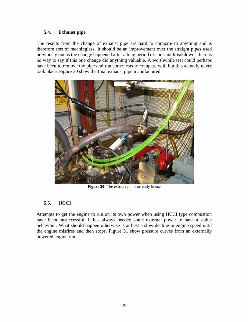
5.4. Exhaust pipe The results from the change of exhaust pipe are hard to compare to anything and is therefore sort of meaningless. It should be an improvement over the straight pipes used previously but as the change happened after a long period of constant breakdowns there is no way to say if this one change did anything valuable. A worthwhile test could perhaps have been to remove the pipe and run some tests to compare with but this actually never took place. Figure 30 show the final exhaust pipe manufactured.
Figure 30: The exhaust pipe currently in use
5.5. HCCI Attempts to get the engine to run on its own power when using HCCI type combustion have been unsuccessful; it has always needed some external power to have a stable behaviour. What should happen otherwise is at best a slow decline in engine speed until the engine misfires and then stops. Figure 31 show pressure curves from an externally powered engine run.

31
Figure 31: Random selection of pressure curves taken from a log of HCCI combustion When looking at complete logs of consecutive cycles from the same run it is clear that all cycles have combustion and that the pressure always reaches around the same maximum, although this happens at different crank angles. The reason why the process is not self-sustaining becomes a little bit clearer when looking at the heat release curves in figure 32. The combustion is very fast as always but it is in some cases very early.
Figure 32: Random selection of heat release curves taken from a log of HCCI combustion
-10
0
10
20
30
40
50
60
70
-75 -50 -25 0 25 50 75
Crank angle [deg]
Cyl
inde
r pre
ssur
e [b
ar]
-10
-5
0
5
10
15
-10 -5 0 5 10 15 20
Crank angle [deg]
Hea
t rel
ease
dQ
/deg
[J]
32
A worthwhile future test would be to try and accomplish HCCI combustion with the regulation mechanism turned on instead of using a fixed phase difference. The heat released would then be adjusted to be on the right side of TDC which could result in a self-sustaining process.
5.6 Scavenging pump Observation of the functionality of the old pump shows that a new pump was required for a reliable engine. Further tests by using pressurized air from the cell show what capacity a new pump should have. Several “new” pumps (diesel vacuum pumps for example) found in scrap yards have been converted to be used with the engine but none worked very well. In the end a new pump from Auto Verdi was bought. For further test results see the master thesis report by Kim Jaktlund (Ref 3).
33
6. Discussion The functionality of the engine has been very erratic. Sometimes it has worked very well and produced a lot of power but more often than not it had some kind of problem. Sometimes it has not even had enough power to sustain itself. Due to these constant interruptions the plan set up in the beginning has had to be changed and/or delayed several times. Most of the work done have focused the solving of the many unforeseen issues that arose instead of performing the beforehand planned tests. However, from the few results that have been presented and also from the general feeling when running the engine, it shows a potential to work very well when all the little problems have been solved. From the beginning, the engine was meant to be in the Shell Eco Marathon car called Aurora. As this car doesn’t need the amount of power available from the engine, a lot of time and work went into finding a way to limit the output in a stable way. Even more time was spent trying to minimize the size and weight of the engine as there were demands for this as well. It is likely that more would have been accomplished had there not been any pressure to adapt an engine that wasn't reliable enough to start with.
7. Conclusions The principle of the engine function works, it is the components surrounding the engine that needs to be adapted to it. A more thorough study of these components is necessary to ensure that they work properly before a more detailed optimization can begin. Proper lubrication, ether the use of oil mixed fuel or an oil pump of sufficient power, is needed to ensure that the piston rings doesn't get clogged by soot. Port injection causes a lot of wall wetting and is too inefficient, especially with a cold engine. Direct injection is better but there is still lot of room for improvement. The engine needs the use of a spark plug when cold. When hot, the engine can run as a true HCCI engine. Optimization is needed before it can be self-sustaining however.

34
8. Recommendations and future work A second engine should be manufactured to minimize down-time and to develop an engine for future use in KTH project cars. A more thorough investigation into the requirements of oil and air should be performed. These should then be fine tuned. Several exhaust pipes should me bought or manufactured and then tested to see what the real impact from using these is. The injection should be improved to minimize wall wetting. Possible improvements could be a deflector plate in front of the injector nozzle or alternatively the use of a more suitable injector. HCCI combustion should be tried with the phase regulation mechanism to see if it can be made self-sustaining. Experiment with a higher degree of involvement of the phase regulation in general and a mapping of the functionality of the engine at different phase angles. Investigate how the engine works at different cylinder block temperatures. Develop a faster start-up procedure. This is perhaps done by solving the injection issue.

35
References [1] David Larsson, “Development of 22” Master of science thesis MMK 2008:36 KTH Industrial engineering and management Machine design SE-100 44 Stockholm [2] Kims Jaktlund, “Development of the HCCI engine” Master of science thesis MMK 2010:01 KTH Industrial engineering and management Machine design SE-100 44 Stockholm
36
Appendix 1: Disassembly manual This is a guide of how to remove the engine from the test bench and then disassemble it. This is necessary so that maintenance or an exchange of parts can be performed. When following this guide it is important to read all the information in a tab before physically doing anything. This is to avoid missing vital information and doing unnecessary extra work. Necessary tools:
• Allen keys (3, 4, 5 mm) • Hex nut keys (8, 10, 13, 18 mm) • Custom cylinder extractor • Custom plate holder • Hose clamp tool • Small flat screwdriver • A few small containers, of a size like paper coffee mugs • A large water container • Circlip pliers • Long nose pliers
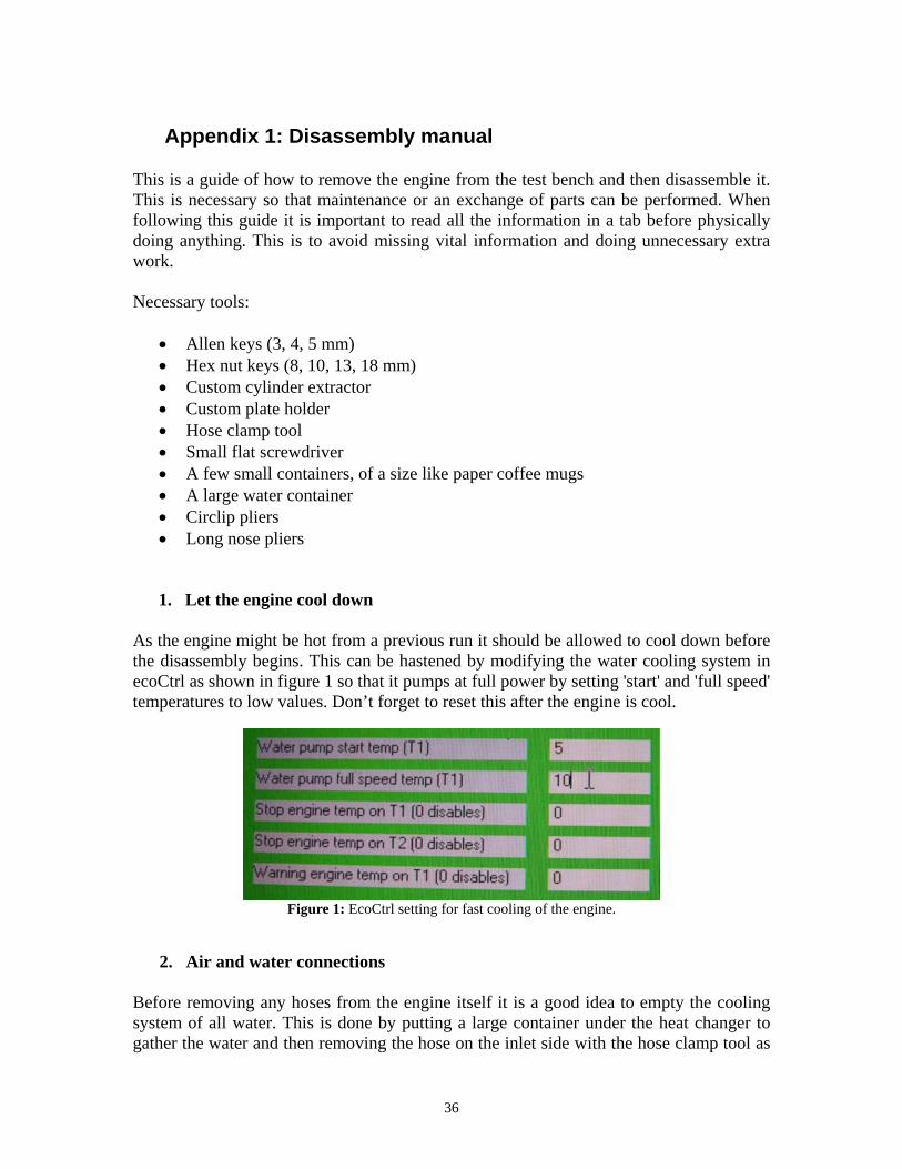
1. Let the engine cool down As the engine might be hot from a previous run it should be allowed to cool down before the disassembly begins. This can be hastened by modifying the water cooling system in ecoCtrl as shown in figure 1 so that it pumps at full power by setting 'start' and 'full speed' temperatures to low values. Don’t forget to reset this after the engine is cool.
Figure 1: EcoCtrl setting for fast cooling of the engine.
2. Air and water connections Before removing any hoses from the engine itself it is a good idea to empty the cooling system of all water. This is done by putting a large container under the heat changer to gather the water and then removing the hose on the inlet side with the hose clamp tool as

37
shown in figure 2. If it is necessary to completely empty the system of water the pump can be activated in the way shown in figure 1.
Figure 2: Removal of the hose on the inlet side of the heat changer After this is done the hoses attached to the engine can be removed using the hose clamp tool. Also remember to reset the parameters in ecoCtrl if they were changed. These hoses are:
• The air hose from the scavenging pump (figure 3) • The water inlet hose • The water outlet hose (figure 4)
Figure 3: Air hose to scavenging pump Figure 4: Cooling water outlet
38
3. Cables These include both cables attached to sensors on the engine and to the controller boxes. The cables that are attached to the engine are these:
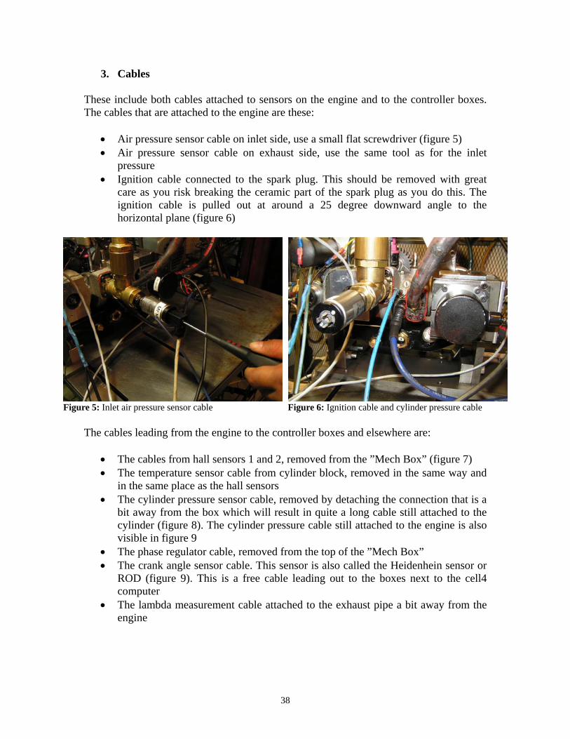
• Air pressure sensor cable on inlet side, use a small flat screwdriver (figure 5) • Air pressure sensor cable on exhaust side, use the same tool as for the inlet
pressure • Ignition cable connected to the spark plug. This should be removed with great
care as you risk breaking the ceramic part of the spark plug as you do this. The ignition cable is pulled out at around a 25 degree downward angle to the horizontal plane (figure 6)
Figure 5: Inlet air pressure sensor cable Figure 6: Ignition cable and cylinder pressure cable The cables leading from the engine to the controller boxes and elsewhere are:
• The cables from hall sensors 1 and 2, removed from the ”Mech Box” (figure 7) • The temperature sensor cable from cylinder block, removed in the same way and
in the same place as the hall sensors • The cylinder pressure sensor cable, removed by detaching the connection that is a
bit away from the box which will result in quite a long cable still attached to the cylinder (figure 8). The cylinder pressure cable still attached to the engine is also visible in figure 9
• The phase regulator cable, removed from the top of the ”Mech Box” • The crank angle sensor cable. This sensor is also called the Heidenhein sensor or
ROD (figure 9). This is a free cable leading out to the boxes next to the cell4 computer
• The lambda measurement cable attached to the exhaust pipe a bit away from the engine

39
Figure 7: Hall sensor connectors Figure 8: Cylinder pressure sensor connection
Figure 9: Crank angle sensor cable connector
4. Oil and fuel connections
This part could be quite messy as you now have to remove parts of the lubrication system and also the injector. Three oil hoses need to be removed when dismounting the lubrication system. Figure 10 shows the crankhouse gas recirculation hose that is removed using the hose clamp tool and figure 11 show one of the oil inlet hoses that are simply pulled off.
Figure 10: Crank house gas ventilation hose Figure 11: Oil inlet hose The injector is removed starting with a 10 mm hex nut key as shown in figure 12. When the nuts are off, the injector itself is removed by simply pulling it out (carefully as always) as it is only held in place inside the cylinder by the friction from an o-ring. It is then preferably put in a container, for example a paper coffee mug like in figure 13.

40
Figure 12: Injector removal Figure 13: Put the injector in a container to prevent spill
5. Large accessories Before you physically remove the engine from the bench it is sensible to also remove the exhaust pipe and also the inlet armature from the cylinder. The exhaust pipe must first be loosened from the stand that holds it in place halfway down as shown in figure 14. When that is done both the inlet armature and the exhaust pipe can be removed using a 3 mm allen key (figures 15 & 16).
Figure 14: Exhaust stand Figure 15: Exhaust pipe Figure 16: Air intake
6. Removing the engine from the test bench At this point there are three things that need to be done in order to be able to carry away the engine:
• Remove the 5 bolts attaching the engine stand to the test bench. These are underside the bench and require a 13 mm hex nut key.
• Pull the engine a bit so that it is separated from the connection to the breaking system. (figure 17)
• Take away the belt connecting the engine to the scavenger pump. (figure 18)

41
Figure 17: Pull away the engine a bit so that it is separated from the braking system
Figure 18: Remove the belt to the scavenging pump
When these steps are done the engine should be carried to the nearest open working space as it will be a lot easier to do the remaining steps there.
7. Spark plug This is an important step to do to prevent unnecessarily damaging the spark plug. Simply use an elongated 8 mm hex nut tool to take away the spark plug as shown in figure 19 and be sure to put it in a safe place afterwards. Also be careful not to loose the copper washer. The spark plug and the washer is shown in figure 20.
Figure 19: Remove the spark plug with care Figure 20: Spark plug and copper washer

42
8. Lubrication system Tip the engine 90 degrees to the gearing side while holding a small container under the nipple from which the crank house gas recirculation hose was removed (figure 10). As before, a paper coffee mug is of sufficient size. When the oil tank is as empty as possible it can be removed using an 18 mm hex nut key in the way shown in figure 21.
Figure 21: Remove oil tank when it is empty
9. Air pump pulley and brake connector The pulley mounted on the intake crankshaft and also the half of the aluminium connector on the exhaust crankshaft can both be removed using a 4 mm allen key as shown in figures 22 and 23. Also shown in these figures is the use of a big screwdriver as a help to prevent the spinning of the wheels.
Figure 22: Pulley for belt to air pump Figure 23: Engine half of brake system connection

43
10. Phase regulating system Now the patented phase regulating system is visible. It consists of the four gearwheels and their mountings, the linear actuator and the arm to which the actuator is connected. To be able to take this apart the middle two gearwheels must first be removed. They are held in place by one circlip on each “pin”. Remove those with circlip pliers in the way shown in figure 24 and then just pull the wheels off their pins. There is no need to remember how the wheels were aligned or in any way mark them as this is already done. More is described about this in the assembly manual.
Figure 24: Remove the circlips and slide off the middle two wheels The crankshaft gearwheels are removed together with the hubs they are mounted on. First the nuts that holds the hubs in place are removed using the custom plate holder and a 10 mm hex nut key (figure 25) and then the custom cylinder extractor together with 4 and 5 mm allen keys is used to force the hubs loose as shown in figure 26. The last part is necessary as the hubs are mounted when heated to get a more secure connection.
Figure 25: Remove the nut that holds the hub in place Figure 26: Force the hub loose using a special tool Now when all the gearwheels are off it is time to remove the linear actuator. This is done at two points. One is the long bolt on the intake side using two 10 mm hex nut keys and a

44
4 mm allen key (figure 27) and the other is the four bolts on the bend in the arm from the exhaust side that are removed with an 8 mm hex nut key and a 4 mm allen key (figure 28).
Figure 27: Intake side actuator connection Figure 28: Remove the 4 bolts on the exhaust side arm The next step is to remove the arm mountings from each side of the engine. They consist of three parts each; an outer part, the arm itself and the inner part that is held in place between the cylinder and the respective crank house. The first two parts are simply removed by taking away the four bolts using a 4 mm allen key as shown in figure 29. The inner part has to be removed by loosening the bolts that attach the engine mounting sides and the crank houses to the cylinder (figure 30). A 10 mm hex nut key is used for this.
Figure 29: Four bolts hold the first two pieces of the arm mounting in place
Figure 30: The bolts on the side of the engine stand needs to be loosened to take away the third part
11. Engine stand The engine stand will not be completely disassembled because it is convenient to use it as a help in some of the remaining steps. The part of the stand that is on the exhaust side

45
will however be removed now by completely taking away the four bolts that were only slightly loosened earlier (figure 30). First though, it is necessary to loosen the connection device from the crankshaft to the Heidenhein sensor (aka ROD) as the mountings for both it and the exhaust side hall sensor use the same bolts. Figure 31 shows how it looks after this step is taken. Also on the left in figure 31 is the Heidenhein sensor mounting with its connector.
Figure 31: Exhaust side with part of the stand removed
12. Crank houses, crankshafts and pistons The crank house together with all the other engine internals can now be removed from the exhaust side by carefully pulling everything out of there as shown in figure 32. When doing this, be sure not to loose the locking ring that is on the side where the Heidenhein sensor was connected.
Figure 32: Remove the crank house and the engine internals by carefully pulling it out

46
When this is done, take away the four bolts on the other side of the engine and put the cylinder on the now empty exhaust side. The parts on the intake side can thereafter be removed (figures 33 and 34). There is another locking ring on this side, be equally careful not to loose it.
Figure 33: Intake side crank house Figure 34: Intake side engine internals In the event that the pistons need to be changed it is also necessary to remove them from the connecting rods. This is done by first removing two locking rings that hold the bolt in place with long nose pliers and then sliding out that bolt. Figure 35 show an example of a removal of a locking ring.
Figure 35: Removal of piston locking ring

47
Appendix 2: Assembly manual This is a guide of how to reassemble the engine from having just completed the disassembly manual. When following this guide it is important to read all the information in a tab before physically doing anything. This is to avoid missing vital information and doing unnecessary extra work. Necessary tools:
• Allen keys (2.5, 3, 4, 6 mm) • Hex nut keys (8, 10, 13, 18 mm) • Custom cylinder extractor • Custom plate holder • Hose clamp tool • Circlip pliers • Long nose pliers • Heat gun • Small flat screwdriver
Necessary chemicals
• Thread locking fluid • Silicone with high temperature tolerance • Grease • Husqvarna LS 2-stroke oil • Water
1. Clean/replace the engine parts After having taken the engine apart, the engine parts will be full of oil, rests of silicone, soot and other things. All parts need to be cleaned from these things except possibly the bearings. As a tip: after wiping down the inside of the cylinder, pour a little fresh oil in and run a free piston with piston rings attached through it to clean away the soot attached to the walls in the middle where the combustion have taken place. Some parts might also need to be replaced. An example of one of those have in the past been the piston rings. They have due to poor lubrication gotten stuck in their grooves and they have had to be broken in order to be removed.
2. Engine internals (intake side) In case a piston was removed from its connecting rod, it is the first to be reattached. Put the bearing inside the rod and then the rod inside the piston. Apply some oil then slide the
48
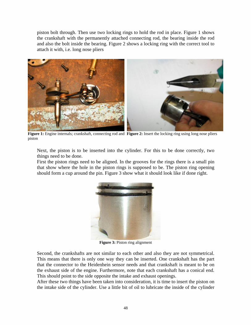
piston bolt through. Then use two locking rings to hold the rod in place. Figure 1 shows the crankshaft with the permanently attached connecting rod, the bearing inside the rod and also the bolt inside the bearing. Figure 2 shows a locking ring with the correct tool to attach it with, i.e. long nose pliers
Figure 1: Engine internals; crankshaft, connecting rod and piston
Figure 2: Insert the locking ring using long nose pliers
Next, the piston is to be inserted into the cylinder. For this to be done correctly, two things need to be done. First the piston rings need to be aligned. In the grooves for the rings there is a small pin that show where the hole in the piston rings is supposed to be. The piston ring opening should form a cup around the pin. Figure 3 show what it should look like if done right.
Figure 3: Piston ring alignment Second, the crankshafts are not similar to each other and also they are not symmetrical. This means that there is only one way they can be inserted. One crankshaft has the part that the connector to the Heidenhein sensor needs and that crankshaft is meant to be on the exhaust side of the engine. Furthermore, note that each crankshaft has a conical end. This should point to the side opposite the intake and exhaust openings. After these two things have been taken into consideration, it is time to insert the piston on the intake side of the cylinder. Use a little bit of oil to lubricate the inside of the cylinder

49
and then insert the piston. Some careful motions back and forth might be necessary as it is somewhat of a tight fit. After the piston is in, slide on the bearings onto the crankshaft and also put the locking ring in its place. Figure 4 show the result.
Figure 4: After inserting the cylinder, slide on the bearings and put the locking ring in place
3. Crank house and engine stand (intake side) First, to prevent leakage of oil and other substances, some silicone has to be applied to the surface of the cylinder that will be connecting to the crank house. After that, put the crank house over the crankshaft as shown in figure 5. Then attach that cylinder side to the engine stand (figure 6). Do not tighten these bolts as the future assembly process will need them to be somewhat loose.
Figure 5: Put the crank house onto the crankshaft Figure 6: Attach the complete intake tide to the engine stand

50
4. Engine internals, crank house and engine stand (exhaust side) Like for the intake side, mind the alignment of the piston rings and also the direction of the crankshaft before inserting the piston. Use some oil for lubrication and slide the piston into the now vertical cylinder. Attach the bearings and make sure the locking ring is in place (figure 7). Then, like for the other side, put some silicone on the cylinder and attach the crank house along with the engine stand side and the hall sensor mounting as they all use the same bolts (figure 8). As with the bolts on the intake side these should not be tightened.
Figure 7: Insert the crankshaft, attach the bearings and put the locking ring in its place
Figure 8: The crank house, the engine stand side and the hall sensor mounting all use the same bolts
Attach the mounting for the Heidenhein sensor (ROD) in much the same way except that now the connection to the crankshaft has to be attached as well as is shown in figure 9. After the bolts for the ROD mounting has been tightened the ROD itself must be aligned properly. To do this the engine needs to be tipped 90 degrees towards the hall sensor side without letting it rest on the sensors or the tips of the crankshafts. Then, 3 mm allen key, loosen the bolts around the ROD using a which will allow it to be moved within the mounting. Make sure it does not pull in any direction by smoothly moving it around and then tighten the bolts once again and tip the engine back. Then put in the lower bolts on the engine mounting (figure 10). These should be tightened with moderate torque.

51
Figure 9: Attach the ROD mounting and align it so that there is no deviation
Figure 10: Use moderate torque to attach the lower bolts on the side of the engine stand
5. Lubrication system At this point it is convenient to attach the oil container underneath the cylinder. This is done by sliding it onto the two nipples under the two crank houses and then securing it there with the cooling water nipple. An 18 mm hex nut key is used for this (figure 11).
Figure 11: Attach the oil tank with the long cooling water nipple
6. Phase regulation parts The first parts to be attached are the inner arm mountings. It is for these that the four bolts on either side of the engine were to be kept loose as these needs to be slid into the hole around the crankshafts. Figures 12 and 13 show how it should look on the intake and exhaust sides of the engine.

52
Figure 12: Inner arm mounting on intake side Figure 13: Inner arm mounting on exhaust side The arms themselves and the outer arm mounting are next being mounted. Remember to grease the arm and the surfaces that it will rotate against. The example used in the pictures is SKF’s general purpose grease. The arm and outer mounting on the intake side is shown in figure 14. Remember also to use thread locking fluid to secure the three small bolts holding the pins for the middle gearwheels (figure 15). These small bolts require a 2,5 mm allen key.
Figure 14: Arm and outer mounting on the intake side Figure 15: Secure the pin bolts by using thread locking fluid
The three pieces are fastened to the crank house with 4 bolts that need a 4 mm allen key. Figure 16 show how the intake side should look when assembled while figure 17 show the assembly order for the exhaust side.

53
Figure 16: The 3 parts are fastened with 4 bolts Figure 17: Exhaust side assembly order The next step is attaching the hubs carrying the outer gearwheels to the crankshafts. Figure 18 show the tools needed for the procedure after the hub has been heated as well as the engine parts themselves. The tools are a special and a 10 mm hex nut key. It is recommended that things are prepared as in figure 18 beforehand as it is difficult to do that once the hub has been heated. When preparing things, note that the gearwheels and the hubs have markings on them. One dot represents the intake side and two dots the exhaust side. At a later stage, these markings are vital to getting the piston movement synchronized so make sure the hubs and gearwheels are matched and that the markings on the gearwheels will face out from the engine when mounted. Also, a good idea would be to turn the crankshafts so that the groove for the pin inside the hub is pointing directly down. Then the pin wont fall out when attaching the hub. Figure 19 show the hub being heated with a heat gun. After being heated for about two minutes the hub should be mounted quickly to the crankshaft to avoid the hub cooling too much. The fastening procedure is shown in figure 20. When dealing with heated components, always use gloves!
Figure 18: Tools and components involved in hub assembly
Figure 19: Heating of the hub with a heat gun
Figure 20: Mount the hub to the crankshaft quickly to avoid too much cooling
54
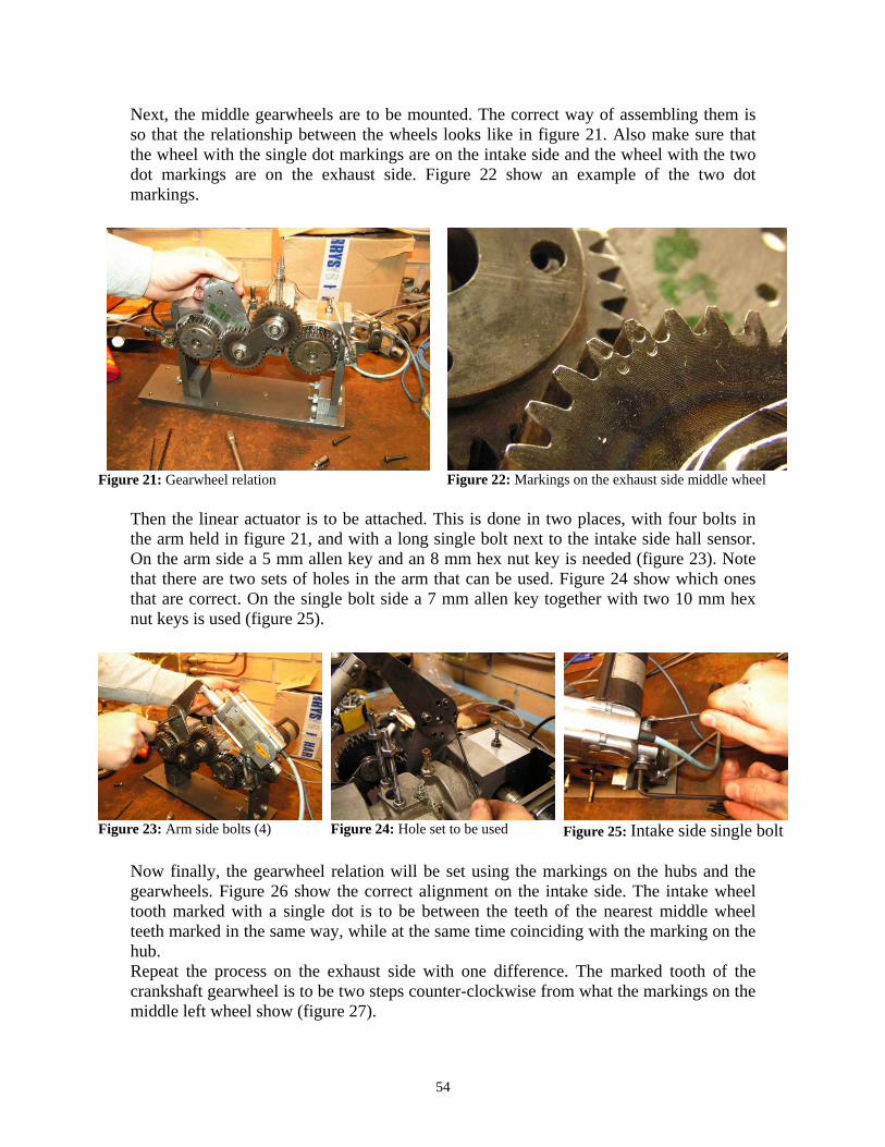
Next, the middle gearwheels are to be mounted. The correct way of assembling them is so that the relationship between the wheels looks like in figure 21. Also make sure that the wheel with the single dot markings are on the intake side and the wheel with the two dot markings are on the exhaust side. Figure 22 show an example of the two dot markings.
Figure 21: Gearwheel relation Figure 22: Markings on the exhaust side middle wheel Then the linear actuator is to be attached. This is done in two places, with four bolts in the arm held in figure 21, and with a long single bolt next to the intake side hall sensor. On the arm side a 5 mm allen key and an 8 mm hex nut key is needed (figure 23). Note that there are two sets of holes in the arm that can be used. Figure 24 show which ones that are correct. On the single bolt side a 7 mm allen key together with two 10 mm hex nut keys is used (figure 25).
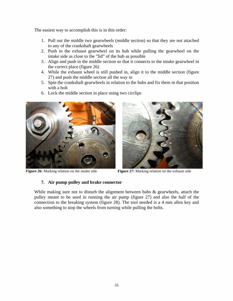
Figure 23: Arm side bolts (4) Figure 24: Hole set to be used Figure 25: Intake side single bolt Now finally, the gearwheel relation will be set using the markings on the hubs and the gearwheels. Figure 26 show the correct alignment on the intake side. The intake wheel tooth marked with a single dot is to be between the teeth of the nearest middle wheel teeth marked in the same way, while at the same time coinciding with the marking on the hub. Repeat the process on the exhaust side with one difference. The marked tooth of the crankshaft gearwheel is to be two steps counter-clockwise from what the markings on the middle left wheel show (figure 27).
55
The easiest way to accomplish this is in this order:
1. Pull out the middle two gearwheels (middle section) so that they are not attached to any of the crankshaft gearwheels
2. Push in the exhaust gearwheel on its hub while pulling the gearwheel on the intake side as close to the ”lid” of the hub as possible
3. Align and push in the middle section so that it connects to the intake gearwheel in the correct place (figure 26)
4. While the exhaust wheel is still pushed in, align it to the middle section (figure 27) and push the middle section all the way in
5. Spin the crankshaft gearwheels in relation to the hubs and fix them in that position with a bolt
6. Lock the middle section in place using two circlips
Figure 26: Marking relation on the intake side Figure 27: Marking relation on the exhaust side
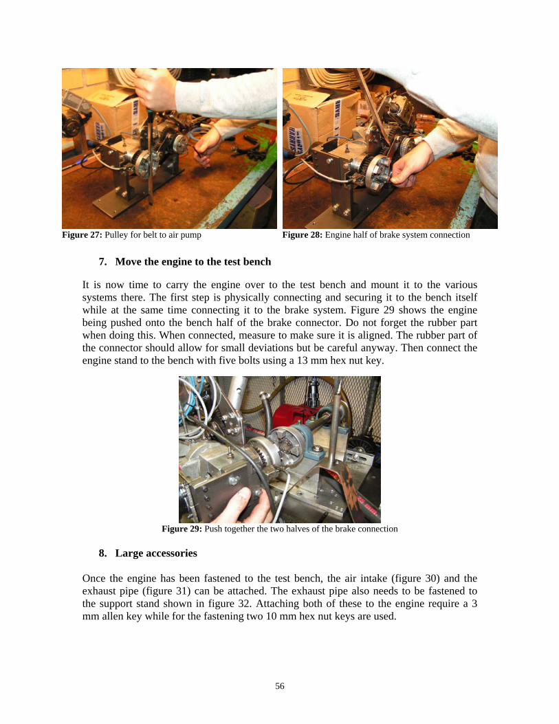
7. Air pump pulley and brake connector While making sure not to disturb the alignment between hubs & gearwheels, attach the pulley meant to be used in running the air pump (figure 27) and also the half of the connection to the breaking system (figure 28). The tool needed is a 4 mm allen key and also something to stop the wheels from turning while pulling the bolts.
56
Figure 27: Pulley for belt to air pump Figure 28: Engine half of brake system connection
7. Move the engine to the test bench It is now time to carry the engine over to the test bench and mount it to the various systems there. The first step is physically connecting and securing it to the bench itself while at the same time connecting it to the brake system. Figure 29 shows the engine being pushed onto the bench half of the brake connector. Do not forget the rubber part when doing this. When connected, measure to make sure it is aligned. The rubber part of the connector should allow for small deviations but be careful anyway. Then connect the engine stand to the bench with five bolts using a 13 mm hex nut key.
Figure 29: Push together the two halves of the brake connection
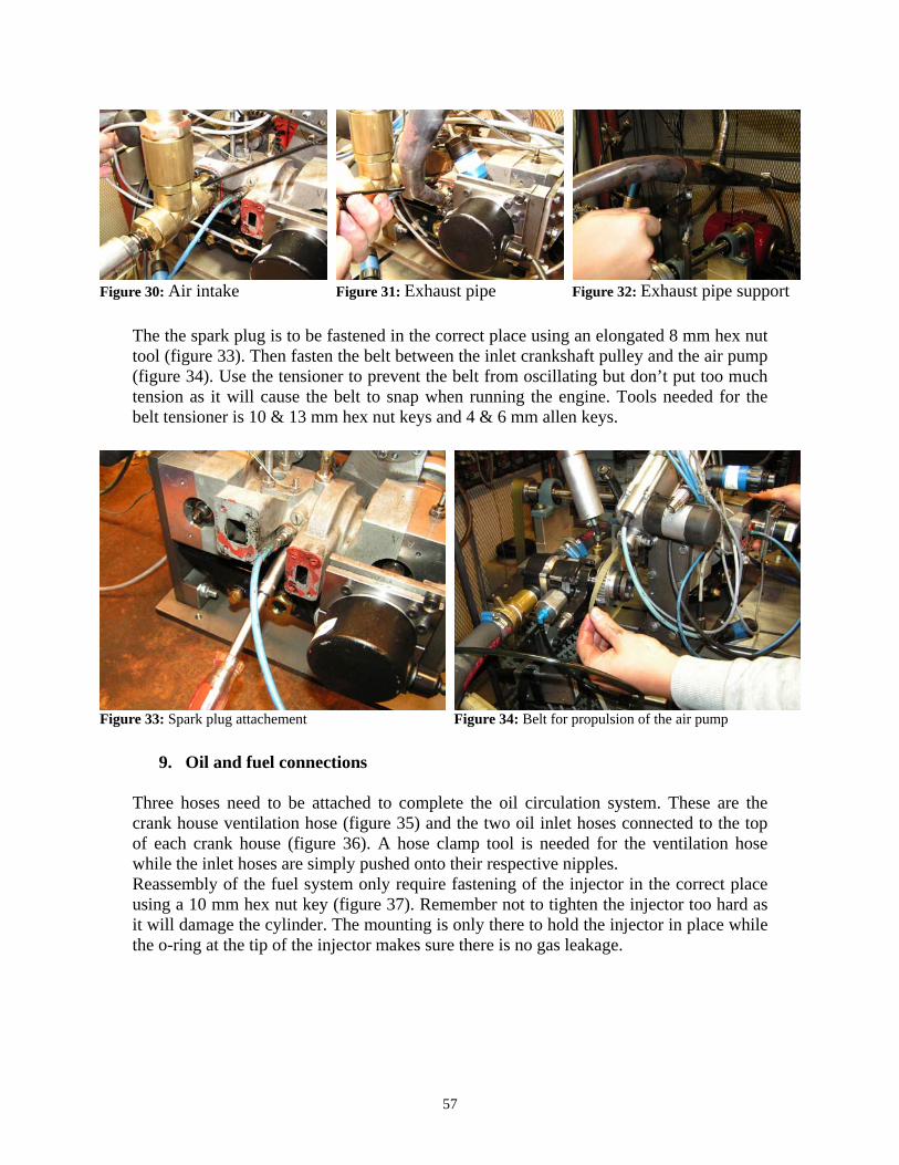
8. Large accessories Once the engine has been fastened to the test bench, the air intake (figure 30) and the exhaust pipe (figure 31) can be attached. The exhaust pipe also needs to be fastened to the support stand shown in figure 32. Attaching both of these to the engine require a 3 mm allen key while for the fastening two 10 mm hex nut keys are used.
57
Figure 30: Air intake Figure 31: Exhaust pipe Figure 32: Exhaust pipe support The the spark plug is to be fastened in the correct place using an elongated 8 mm hex nut tool (figure 33). Then fasten the belt between the inlet crankshaft pulley and the air pump (figure 34). Use the tensioner to prevent the belt from oscillating but don’t put too much tension as it will cause the belt to snap when running the engine. Tools needed for the belt tensioner is 10 & 13 mm hex nut keys and 4 & 6 mm allen keys.
Figure 33: Spark plug attachement Figure 34: Belt for propulsion of the air pump
9. Oil and fuel connections Three hoses need to be attached to complete the oil circulation system. These are the crank house ventilation hose (figure 35) and the two oil inlet hoses connected to the top of each crank house (figure 36). A hose clamp tool is needed for the ventilation hose while the inlet hoses are simply pushed onto their respective nipples. Reassembly of the fuel system only require fastening of the injector in the correct place using a 10 mm hex nut key (figure 37). Remember not to tighten the injector too hard as it will damage the cylinder. The mounting is only there to hold the injector in place while the o-ring at the tip of the injector makes sure there is no gas leakage.
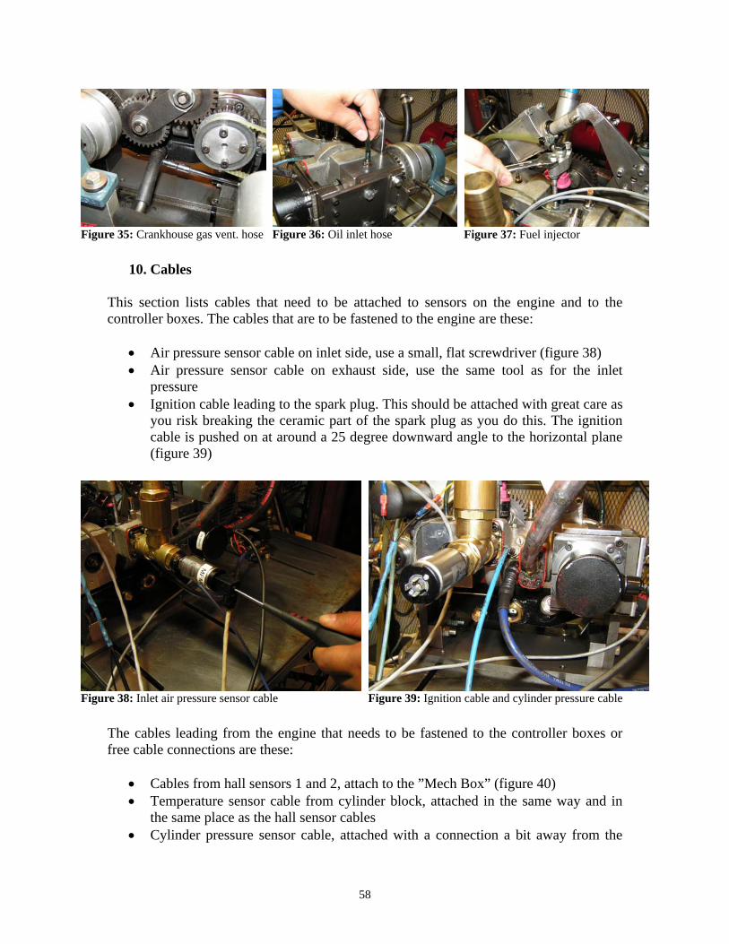
58
Figure 35: Crankhouse gas vent. hose Figure 36: Oil inlet hose Figure 37: Fuel injector
10. Cables This section lists cables that need to be attached to sensors on the engine and to the controller boxes. The cables that are to be fastened to the engine are these:
• Air pressure sensor cable on inlet side, use a small, flat screwdriver (figure 38) • Air pressure sensor cable on exhaust side, use the same tool as for the inlet
pressure • Ignition cable leading to the spark plug. This should be attached with great care as
you risk breaking the ceramic part of the spark plug as you do this. The ignition cable is pushed on at around a 25 degree downward angle to the horizontal plane (figure 39)
Figure 38: Inlet air pressure sensor cable Figure 39: Ignition cable and cylinder pressure cable The cables leading from the engine that needs to be fastened to the controller boxes or free cable connections are these:
• Cables from hall sensors 1 and 2, attach to the ”Mech Box” (figure 40) • Temperature sensor cable from cylinder block, attached in the same way and in
the same place as the hall sensor cables • Cylinder pressure sensor cable, attached with a connection a bit away from the

59
“Mech Box” (figure 41) • Phase regulator cable, to be attached on the top of the ”Mech Box” • Crank angle sensor cable (figure 42). This cable is to be attached to a cable
coming directly from the boxes out by the cell4 computer • Lambda sensor cable. This is attached to a cable coming directly from the lambda
measurement unit out by the ecoCtrl laptop
Figure 40: Hall sensor connectors Figure 41: Cylinder pressure sensor connection
Figure 42: Crank angle sensor cable connector
11. Air and water hoses
To complete the water and air connections three hoses need to be attached using the hose clamp tool. These hoses are:
• The air hose from the scavenging pump (figure 43) • The water inlet hose, attached under the oil container • The water outlet hose (figure 44)
Figure 43: Air hose to scavenger pump Figure 44: Cooling water outlet

60
Appendix 3: Calibration of Heindenhein sensor The calibration is performed as follows:
1. Run the engine with electric motor only (drag the engine). Perform steps 2 and 3 while the engine is motored
2. Set the phase difference to 0 degrees in ecoCtrl (Ctrl + P) 3. When the phase difference have changed and the engine is running smoothly, take
a fastlog in cell4 4. Stop running the engine 5. Open the fastlog file in Mkpad4 and save the file in ASCII by going to the menu
File->'Save ASCII as..' and set up the save parameters as shown in figure 45 6. Open the ASCII file created in excel and make a graph with engine pressure as a
function of crank angle as shown in figure 46 (use columns A and B) 7. Find the peak pressure value and note at what angle it occurs 8. In cell4, go to menu choices ChannelSetupScreen->ChannelGroup->'Logical
channels' (figure 47) and change the ”CA marker after TDC degrees (normally -)” value by as much as the angle noted in step 7.
For example, look at the value in figure 47. If the angle where peak pressure occurred in step 7 was at -50 degrees (50 degrees before TDC marker) then reduce the already noted value by 50 making it -72.2
9. Test the calibration by performing steps 1-7 again. If the peak pressure occurs at 0 degrees, the calibration is done. If not, the physical connector is probably not fastened hard enough and is spinning. Fasten it properly and go to step 1.
10. If the value in the setup shown in figure 47 end up close to 0 (TDC), it is necessary to physically spin the ROD connector half a revolution so that the CA marker signal from the ROD is sent close to BDC instead. If this is the case, the calibration procedure has to start over, go to step 1.

61
Figure 45: 'Save ASCII as..' setup screen
Figure 46: Cylinder pressure graph
Figure 47: 'Logical channels' setup screen

62
Appendix 4: Projektplanering examensarbete
Bakgrund Många företag som har någon form av motorutveckling har någon gång försökt sig på att utveckla en HCCI-motor. I de flesta fall har detta misslyckats och den vanligaste orsaken har varit att förbränningsprocessen är för svår att reglera. Hans-Erik Ångström har tagit fram en patenterad lösning på detta problem och tester huruvida denna lösning är effektiv är en huvuduppgift i detta examensarbete.
Syfte Anledningen till att man vill utveckla HCCI-drift är att man vill ta fram en alternativ förbränningsprocess som har så lite utsläpp som möjligt. Driften som sådan använder sig av fördelar både från OTTO-motorn och från Dieselmotorn men har få av dessa motortypers nackdelar. En HCCI-förbränning sker i en homogen bränsle/luft-blandning på låg värme och förbränningen sker mycket fort. Detta har som effekt att man får låga utsläpp av NOx samt en hög verkningsgrad.
Mål Ett första delmål är att anpassa en motorprovcell till fortsatt utveckling av HCCI-motorn. Detta inkluderar att städa bort det mesta i form av kablar och elektroniska komponenter för att sedan kunna montera ny utrustning från grunden. Den nya utrustningen inkluderar elkablar, signalkablar och sådan elektronik som möjliggör att man skall kunna utföra mätningar på och övervaka en motor i drift både säkert och störningsfritt. Detta arbete kräver i den första fasen, dvs. röjningen av provcellen, ingen speciell kompetens utan endast en hel del tid nerlagd då provcellen är mycket rörig. Dock så behövs en viss kompetens inom ellära då den nya utrustningen skall monteras och de nya kablarna dras. Tid som erfordras för att uppnå detta mål beräknas till ca 6 veckor och arbetet kommer att ske så fort som möjligt men då även parallellt med arbetet mot delmål två då de två målen beror till en viss del på varandra. Ett andra delmål är att ta fram en bas för en repeterbar testprocess för utvecklandet av denna motor. Detta innebär att man tillverkar eller köper driftsäker kringutrustning eller säkerhetsställer att de komponenter som redan finns fungerar som de skall. Syftet med detta är att få en så stabil motor som möjligt där så få saker som möjligt kan ändra sig från mellan olika motortest. Arbetet kräver förhållandevis stor kompetens inom mekanik och maskinkonstruktion och även erfarenhet av att ha hanterat just denna specifika motor med dess specifika särdrag.
John Larsson Kim Jaktlund 1/9 2008

63
Detta delmål är den mekaniska motsvarigheten till delmål ett. Man måste klara båda delmålen för att sedan kunna gå vidare med utvecklingsprocessen. Tiden för att klara av detta beräknas vara mellan 8 till 12 veckor. Delmål tre är att se till att man får en stabil tvåtaktsförbränning. Denna skall vara driftsäker och snabb att uppnå. Då detta i princip redan uppnåddes under föregående termin och då dessutom under ogynnsamma förhållanden så borde detta arbete inte ta mer än ett par veckor. Kompetensen som krävs för detta arbete är dels att kunna hur systemen i och kring motorprovcellen fungerar och dels behövs kunskaper inom förbränningsmotorteknik, maskinteknik och mekatronik. Tanken med detta är motorn då skall kunna fungera som kraftkälla i bilen Spiros. För att detta skall bli verklighet så måste studenterna från mekatronik få en motor att anpassa systemen i tävlingsbilen till. Huvudmålet är att utveckla en motor som går med stabil HCCI-drift. Detta mål är högt satt men det är vad som kommer strävas efter under resterande arbetstiden. Kompetenskrav kommer även här att inkludera höga nivåer av kunnande inom förbränningsmotorteknik, maskinteknik och mekatronik.
Metod Genom framtagning av nya komponenter och optimering av redan befintliga sådana skall en stabil plattform för utveckling av en HCCI-motor byggas. Utifrån denna ska sedan repeterbara tester kunna genomföras i syfte att ta fram en så effektiv HCCI-drift som möjligt.
Tidsplan Examensarbetets varaktighet är enligt kontrakt från den 1/9 2008 och skall sträcka sig över 20 veckor. Enligt muntlig överenskommelse kommer arbetet istället att ske på halvfart och då sträcka sig fram till juni 2009. Bifogad är en mer detaljrik planering över hur arbetstiden kommer att delas upp.
Bearbetning cylinder
Design Framtagning av ny tryckgivaradapter samt verktyg för fastsättning av denna i cylindern.
Bearbetning Tillverkning av ovanstående delar samt exempelvis planing av yta på cylindern för montering av dessa.

64
Montering Montering av cylinder med kolv, vevaxel, ramlager, tryckgivaradapter etc.
Städning av celler 2 & 3
Rensning av kabel En ny provcell skall användas för detta examensarbete. Det som krävs för detta är förarbete i form av borttagande av gammalt kablage både i den nya och i den gamla cellen.
Kabeldragning
Strömmatning Nya kablar för elförsörjning till såväl motor som mätutrustning skall dras.
Signalkablar Kablar för informationsöverföring mellan motor och styrsystem samt mellan motor och dator skall dras.
Kringsystem För att utveckling av motorn ska kunna ske någorlunda effektivt så ska tillförlitligheten till kringkomponenter vara hög. Därför skall dessa testas var för sig innan de sätts samman med motorn.
Hydraulbroms Detta innebär design, tillverkning och montering av hydraulbroms samt även test av dess funktionalitet. Denna punkt kommer i slutskedet även inkludera framtagandet av ett kylsystem till hydrauloljan som finns i bromsen.
Bränslevåg och bränslesystem Ny placering av bränslevåg utanför testbänk samt test av komponenter i bränslesystemet. Dessa sistnämnda är bränslevågen, bränslepumpen och tryckregulatorn. Slutligen ingår även montering av dessa.
Insprutning Test av spridarfunktion samt styrsystem till denna. Under denna tid kommer möjligen även tillverkning, montering och test av deflektorplatta till insprutaren att ske. Ett krav för att denna punkt skall kunna genomföras är att bränslesystemet i föregående punkt är färdigt.

65
Spolpump Test av funktion samt utveckling av smörjsystem till befintlig spolpump. Alternativt om det bedöms aktuellt och om också tid finns tillgängligt skall ny spolpump inköpas eller utvecklas. Under denna punkt ingår även montering och test av flödesmätningsutrustning.
Smörjning Kontroll av funktion hos smörjsystemet. Detta inkluderar test av oljepump och bedömning av grad av oljeinblandning i bränsle.
Tändning Tillverkning av nya tändhattar som ej hoppar av under drift. Tiden som läggs ner på denna punkt är tvådelad där man under det första stadiet undersöker vilka lösningar som finns tillgängliga för beställning. Alternativt så måste tillverkning av nya tändhattar ske. Den senare tiden har avsatts för test och montering av den beställda/egentillverkade tändhatten.
Motorkylning Design och utveckling, montering samt test av kylsystem.
Test motor
Test av mätutrustning Kontroll av att all mätutrustning skickar det de skall samt att den är korrekt kalibrerad både i givare och i dator.
Motorstyrning Konfigurering av parametrar för motorstyrning.
Mekanik Finjustering av mekaniska detaljer i och kring motorn.
Reservtid Erfarenhet från förra terminen har visat att man behöver tid avdelad som buffert för att kunna ha utrymme för saker som beställningstider och extraarbete.
Förberedelse motortester
Utformning av testmetod Standardmetodiken som skall följas vid alla tester skall utformas här.

66
Planering tester Här skall planeringen för vilka tester som skall utföras fastslås.
Motortester Denna tid inkluderar förutom själva motortesterna (av tex optimalt varvtal) även analys och reflektion av resultat från tester. Dessa kommer att ske efterhand som testerna blir klara. En plan mer i detalj om vad som skall testas kommer efterhand att utformas och bli klar först under föregående punkt.
Rapportskrivning Tid avsatt för skrivandet av exjobbsrapporten samt även den muntliga presentationen.
Shell Eco-marathon Spiros kommer att tävla i Shell Eco-marathon sista veckan i maj. Denna tävling är år 2009 i tyskland och vi som gör examensarbete kommer naturligtvis vara med ifall något skulle hända.
Redovisning Här kommer den muntliga redovisningen av examensarbetet att ske samt den skriftliga rapporten lämnas in.
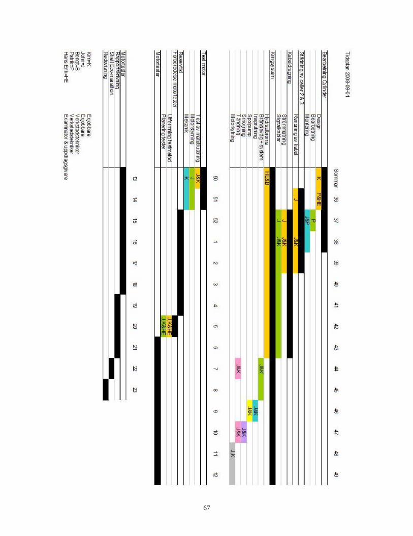
67