thermal remediation services, inc. · thermal remediation services, inc. thermal remediation ......
TRANSCRIPT
Thermal RemediationServices, Inc.
Thermal RemediationServices, Inc.
Electrical Resistance Heatingfor Rapid
Remediation of DNAPLApril 2003
David Fleming425-396-4266
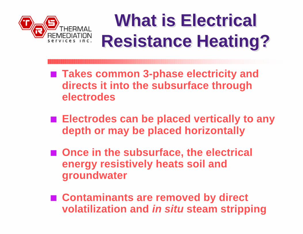
What is ElectricalResistance Heating?
What is ElectricalResistance Heating?
n Takes common 3-phase electricity anddirects it into the subsurface throughelectrodes
n Electrodes can be placed vertically to anydepth or may be placed horizontally
n Once in the subsurface, the electricalenergy resistively heats soil andgroundwater
n Contaminants are removed by directvolatilization and in situ steam stripping
Why ElectricalResistance Heating?
Why ElectricalResistance Heating?
§ Heating is uniform with no bypassedregions
§ Heating is rapid – months vs. years
§ Steam is produced in situ
§ Preferentially heats tight soil lenses andDNAPL hot spots
§ Cost effective: most commercial, full-scalesites range from $30-$90 per yds3 (sitespecific)

ApplicationsApplications
§ Low permeability & heterogeneous lithologies
§ DNAPL & LNAPL cleanups by aquifer andsmear zone heating
n Heavy hydrocarbon mobilization
n Bioremediation enhancement
n Remediation underneath operating facilities
n Remediation in the presence of buried utilitiesand hazardous waste drums

In-Situ SteamGeneration
In-Situ SteamGeneration
HEATEDZONE
Electrode & Co-located VR Wells
2. Steam generation is uniform through the heated zone
1. Soil grains act as electrical resistors
150 V to400 V
Safe<15 V
3. Discrete intervals canbe heated
Electrode & Co-located VR Wells
TMP
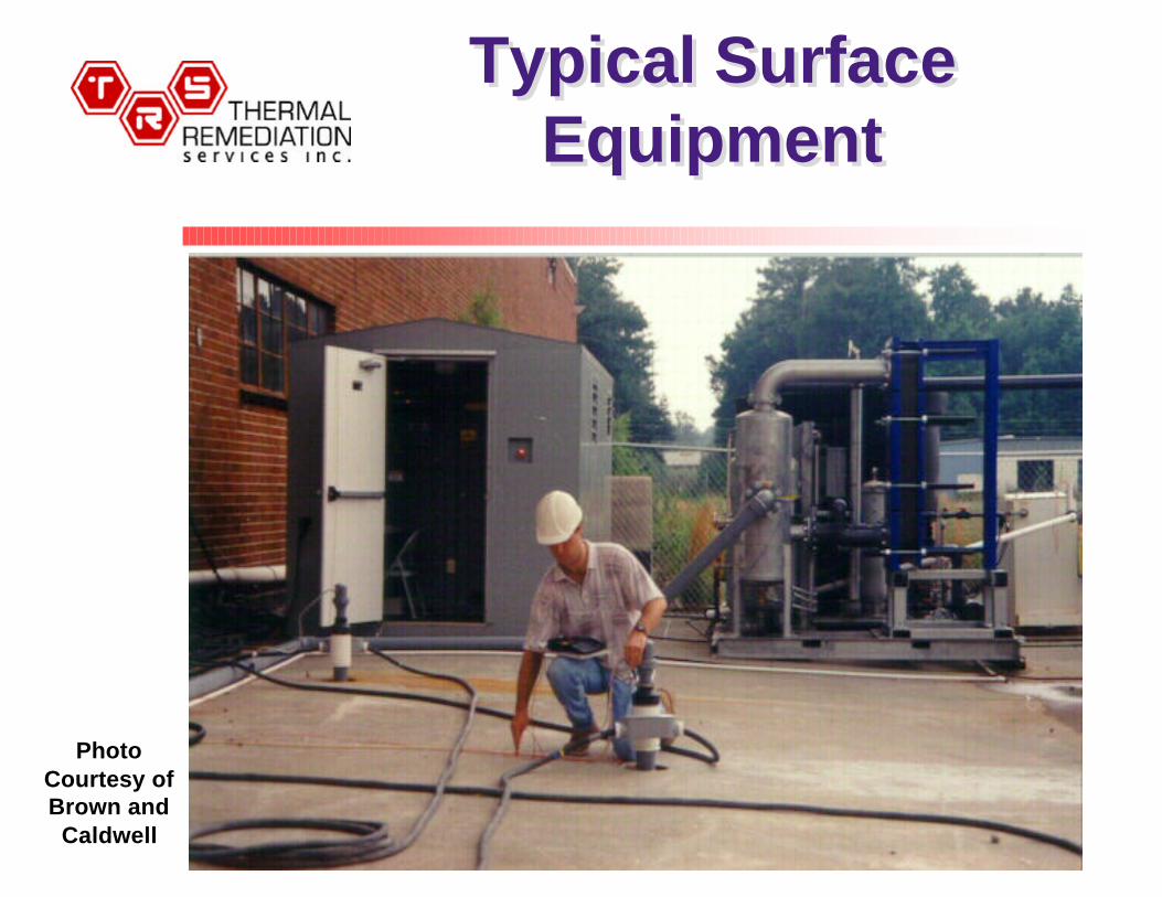
Typical SurfaceEquipment
Typical SurfaceEquipment
PhotoCourtesy ofBrown and
Caldwell
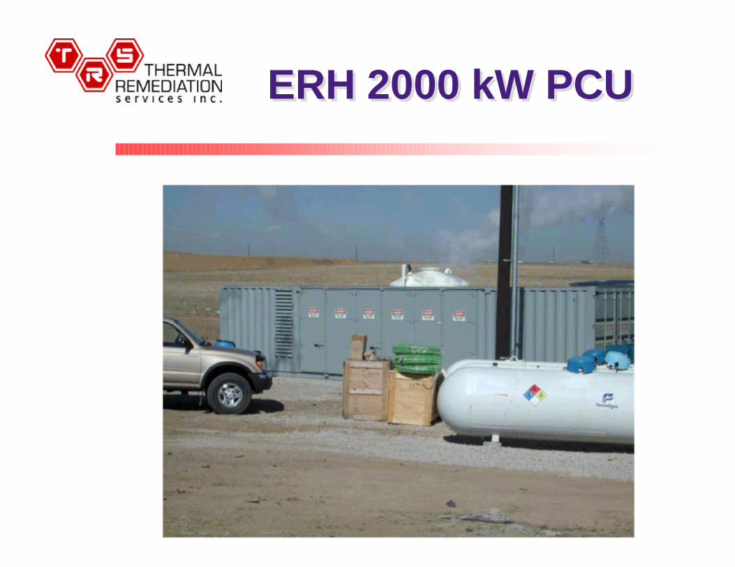
ERH 2000 kW PCUERH 2000 kW PCU
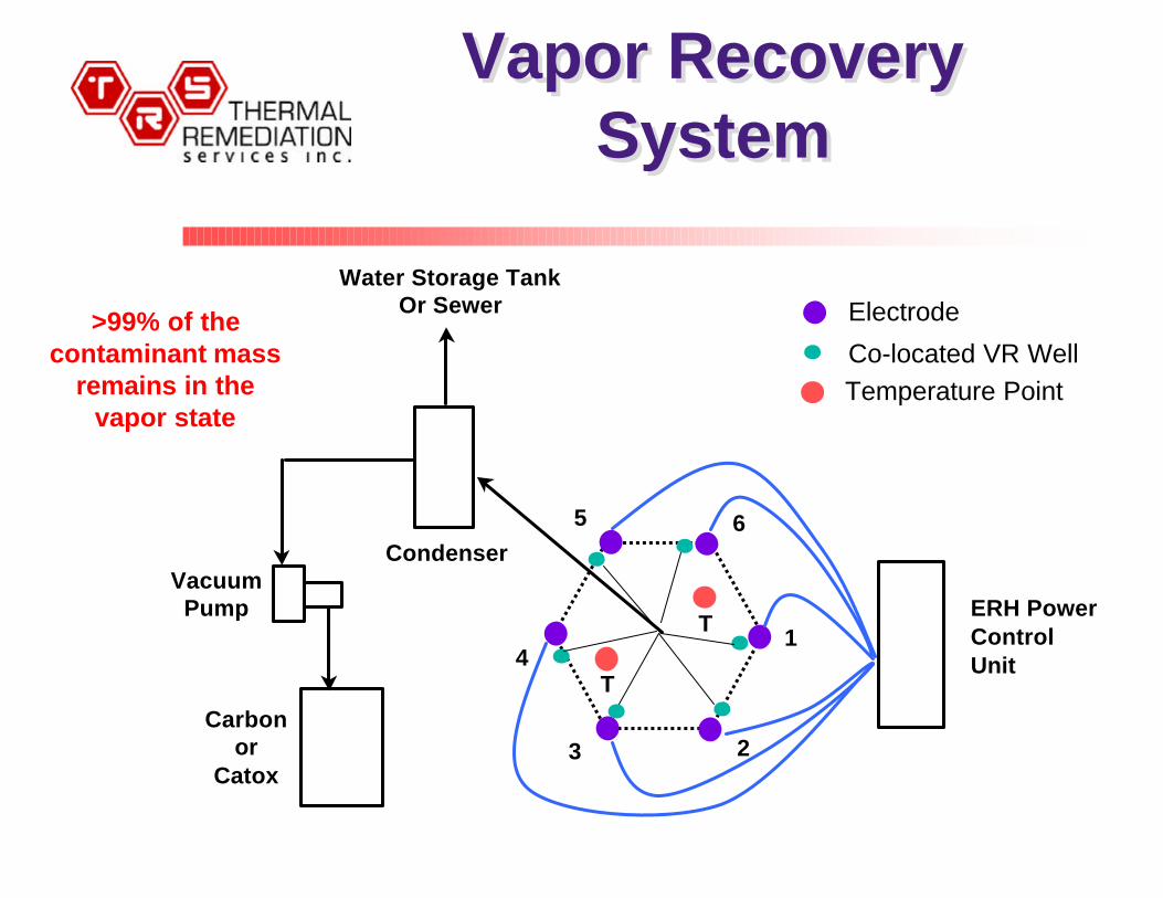
Vapor RecoverySystem
Vapor RecoverySystem
ERH Power Control Unit
Water Storage TankOr Sewer
VacuumPump
Carbonor
Catox
Condenser
1
23
4
5 6
T
T
>99% of thecontaminant mass
remains in thevapor state
Electrode
Co-located VR WellTemperature Point
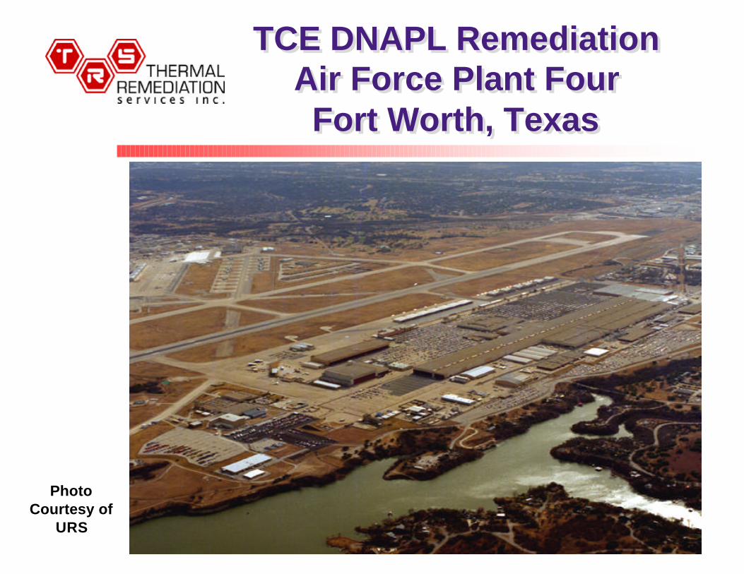
TCE DNAPL RemediationAir Force Plant FourFort Worth, Texas
TCE DNAPL RemediationAir Force Plant FourFort Worth, Texas
PhotoCourtesy of
URS
Full-Scale ERH atAF Plant 4
Full-Scale ERH atAF Plant 4
§ Full-scale ERH covering 1/2 acre area inside andoutside of Bldg. 181, manufacturing operations 24/7§ 70 electrodes and co-located VR wells installed in and
around existing tanks, piping and equipment (32° angles)
§ Heterogeneous silt, clay and gravel with a highlyweathered limestone, competent bedrock at 32 ft bg§ Groundwater at 27 ft bg§ Electrodes electrically conductive 3 to 32 ft bg§ Two vapor and steam recovery intervals in perimeter
electrodes§ ERH operations May to Aug 2002; reduced – Dec ‘02§ Goal – average 90% reduction based on a 95% UCL
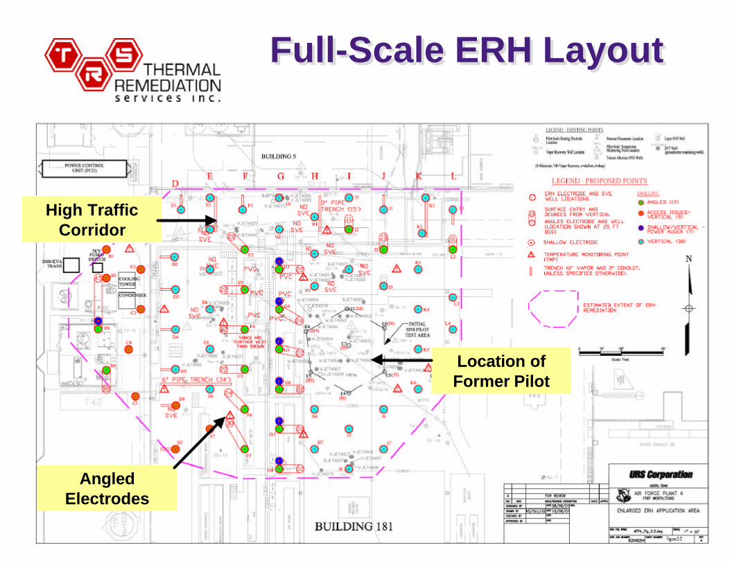
Full-Scale ERH LayoutFull-Scale ERH Layout
High TrafficCorridor
Location ofFormer Pilot
AngledElectrodes
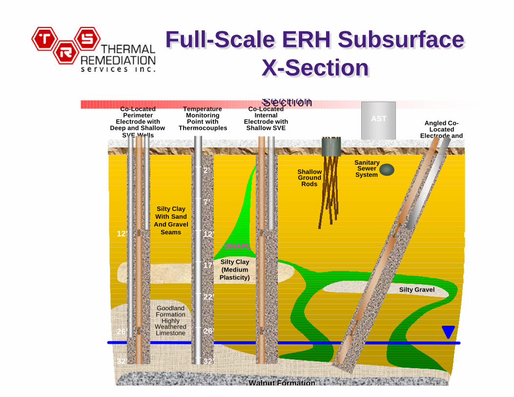
Full-Scale ERH SubsurfaceX-Section
Full-Scale ERH SubsurfaceX-Section
DNAPL
Co-LocatedPerimeter
Electrode withDeep and Shallow
SVE Wells
Co-LocatedInternal
Electrode withShallow SVE
Walnut FormationWalnut Formation
E R H S u b s u r f a c e C r o s sS e c t i o n
E R H S u b s u r f a c e C r o s sS e c t i o n
GoodlandFormation
HighlyWeatheredLimestone
Angled Co-Located
Electrode andSVE
AST
SanitarySewer
System
Silty Clay(Medium
Plasticity)
Silty Gravel
ShallowGroundRods
TemperatureMonitoringPoint with
Thermocouples
T
T
T
T
T
T
T
12’
26’
32’
2’
7’
12’
17’
22’
26’
32’
Silty ClayWith SandAnd Gravel
Seams
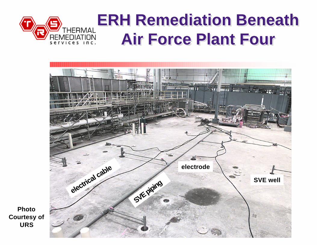
ERH Remediation BeneathAir Force Plant Four
ERH Remediation BeneathAir Force Plant Four
SVE pipingelectric
al cable electrode
SVE well
PhotoCourtesy of
URS
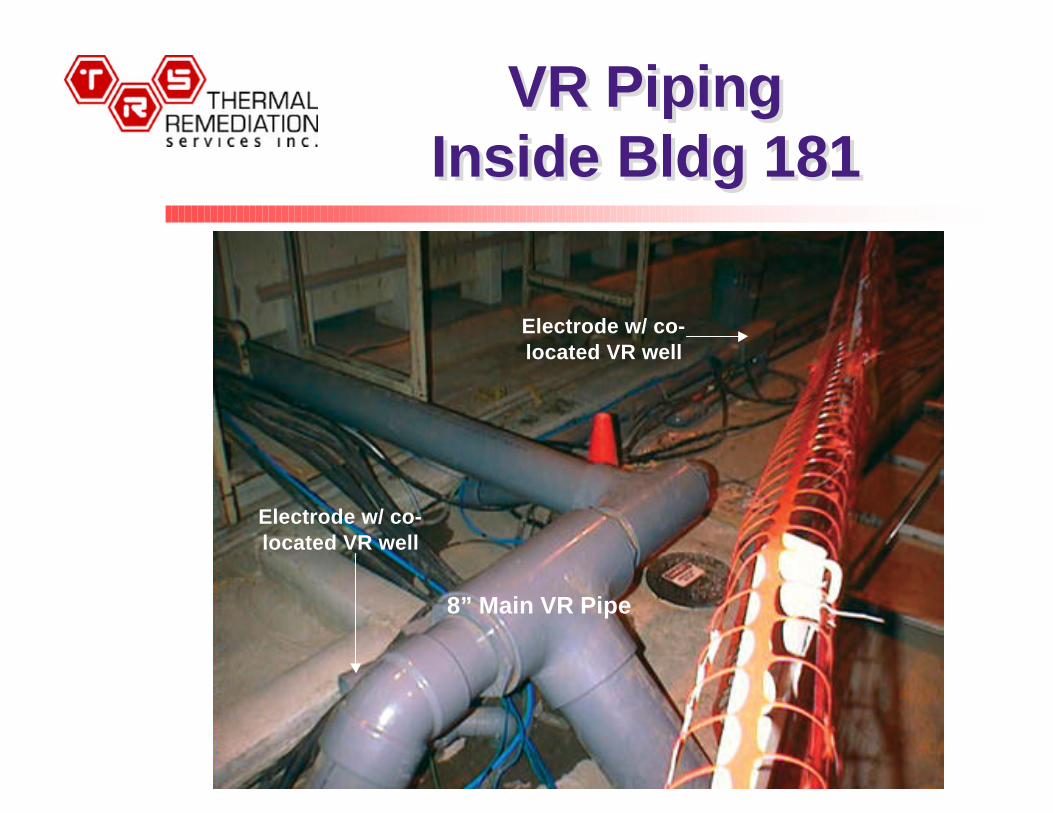
VR PipingInside Bldg 181
VR PipingInside Bldg 181
8” Main VR Pipe
8” Main VR Pipe
Electrode w/ co-located VR well
Electrode w/ co-located VR well

Close Up ofERH Electrode
Close Up ofERH Electrode
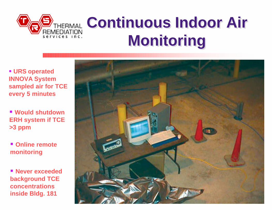
Continuous Indoor AirMonitoring
Continuous Indoor AirMonitoring
§ URS operatedINNOVA Systemsampled air for TCEevery 5 minutes
§ Would shutdownERH system if TCE>3 ppm
§ Online remotemonitoring
§ Never exceededbackground TCEconcentrationsinside Bldg. 181
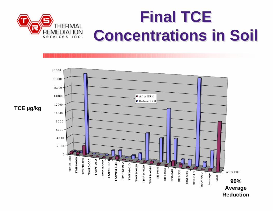
Final TCEConcentrations in Soil
Final TCEConcentrations in Soil
After ERH
0
2 0 0 0
4 0 0 0
6 0 0 0
8 0 0 0
10000
12000
1 4 0 0 0
16000
1 8 0 0 0
2 0 0 0 0
After ERH
Before ERH
TCE µg/kg
90%Average
Reduction
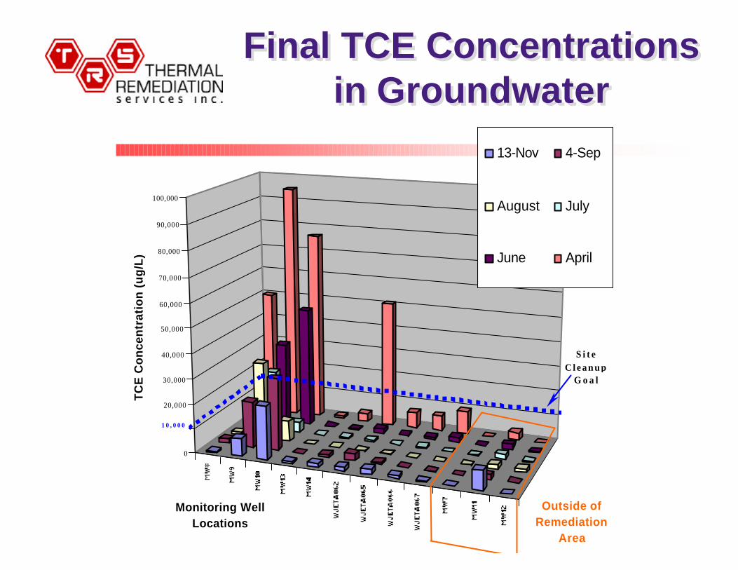
Final TCE Concentrationsin Groundwater
Final TCE Concentrationsin Groundwater
0
10,000
20,000
30,000
40,000
50,000
60,000
70,000
80,000
90,000
100,000
TC
E C
on
cen
trat
ion
(u
g/L
)13-Nov 4-Sep
August July
June April
S i t e C l e a n u p
G o a l
1 0 , 0 0 0
Outside of Remediation
Area
Monitoring Well Locations
Results at AF Plant 4Results at AF Plant 4
§ Area & volume treated - 22,000 sq. ft. & 27,400cubic yards – from May to Dec 2002
§ Average weekly power input – 563 kW§ Recovered ~ 1,600 lbs. TCE§ Met groundwater goal following 4 months of ERH
operations, ~ 93% average reduction in TCEconcentrations in groundwater
§ Met soil goal, 90% average reduction§ TCE concentrations never exceeded background
levels of TCE in the indoor breathing space§ No impacts to manufacturing operations§ $57 per cubic yard

Polishing MechanismsPolishing Mechanisms
n Hydrolysis of Halogenated Alkanesu Compounds such as TCA have a hydrolysis half-life of
less than one day at steam temperatures.
n Iron Reductive Dehalogenationu Steel shot used as electrode backfill provides an iron
source for reductive dehalogenation (iron filing wall)
n Temperature Accelerates Reactionsu The above reaction rates are increased by factor of
thousands at 100°C (Arrhenius Equation)
n Bioremediation by Thermophilesu Thermophilic bacteria are the most effective solvent
dehalogenators and prefer 40-70°C
www.Thermalrs.comwww.Thermalrs.com