thermal analysis free guide - fea for all |and all about...
TRANSCRIPT

A Guide to Thermal AnalysisThis guide starts from applications of thermal analysis and its role in simulation driven design. Fundamental concepts and principles will be introduced such as conduction, convection, radiation, linear and nonlinear heat transfer, steady state and transient analysis, etc.

Page 3
About the author:My name is Cyprien Rusu, I am a French CAE engineer who wants to teach the right bases of FEA Simulation to designers, engineers and everyone aspiring to get it right!
Hundreds of FEA students followed my free FEA webinars on Youtube, read my blog articles on feaforall.com and joined my FEA courses to learn more and improve their understanding of FEA and become better engineers!
I have also taught FEA seminars to FEA engineers from all over the world…
Do you want to join my free FEA course?
If not, click on the link below and join the course to get a basic understanding of the FEA foundations that you need to have:
Join the free FEA course
Page 3
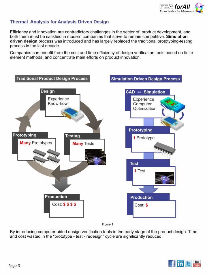
Efficiency and innovation are contradictory challenges in the sector of product development, and both them must be satisfied in modern companies that strive to remain competitive. Simulation driven design process was introduced and has largely replaced the traditional prototyping-testing process in the last decade. Companies can benefit from the cost and time efficiency of design verification tools based on finite element methods, and concentrate main efforts on product innovation.
Design
Experience Know-how
Prototyping
Many Prototypes
Production
Cost: $ $ $ $
Traditional Product Design Process Simulation Driven Design Process
CAD ⇔ SimulationExperience Computer Optimization
Prototyping
1 PrototypeTesting
Many Tests
Test1 Test
Production
Cost: $
Thermal Analysis for Analysis Driven Design
By introducing computer aided design verification tools in the early stage of the product design. Time and cost wasted in the “prototype - test - redesign” cycle are significantly reduced.
Figure 1
Page 3
Thermal related problems are challenges commonly faced by product design engineers. Some of the problems include overheating, excessive thermal stresses, thermal effect on dimensional stability, etc. Following are some applications in which thermal factors need to be considered.
Thermal Analysis Application
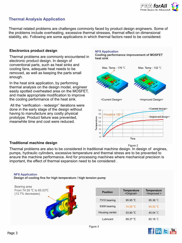
Electronics product design Thermal problems are commonly encountered in electronic product design. In design of conventional parts, such as heat sinks and cooling fans, adequate heat needs to be removed, as well as keeping the parts small enough. In the heat sink application, by performing thermal analysis on the design model, engineer easily spotted overheated area on the MOSFET, and made appropriate modification to improve the cooling performance of the heat sink. All the “verification - redesign” iterations were done in the early stage of the design without having to manufacture any costly physical prototype. Product failure was prevented, meanwhile time and cost were reduced.
Max. Temp : 176 ℃ Max. Temp : 132 ℃
<Current Design> <Improved Design>
NFX Application Cooling performance improvement of MOSFET heat sink
Traditional machine design Thermal problems are also to be considered in traditional machine design. In design of engines, pumps, hydraulic cylinders, excessive temperature and thermal stress are to be prevented to ensure the machine performance. And for processing machines where mechanical precision is important, the effect of thermal expansion need to be considered .
Position Temperature<Original>
Temperature<Improved >
7310 bearing 95.95 ℃ 95.38 ℃
6309 bearing 74.55 ℃ 65.53 ℃
Housing center 53.80 ℃ 45.04 ℃
Lubricant 69.27 ℃ 62.16 ℃
Bearing area From 74.55 ℃ to 65.53℃ (13.7% decreases)
NFX Application Design of cooling fins for high temperature / high tension pump
Figure 2
Figure 3
In the application above, cooling fins were designed to prevent overheating of a pump which operates under high temperature and high pressure environment.
Page 3
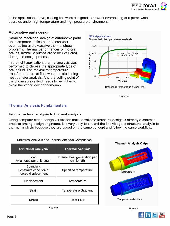
Automotive parts design Same as machines, design of automotive parts and components also need to consider overheating and excessive thermal stress problems. Thermal performances of motors, brakes, hydraulic pumps are to be evaluated during the design process. In the right application, thermal analysis was performed to choose the appropriate type of brake fluid. The maximum temperature transferred to brake fluid was predicted using heat transfer analysis. And the boiling point of the chosen brake fluid needs to be higher to avoid the vapor lock phenomenon.
Tem
pera
ture
(℃)
0
225
450
675
900
Time (s)0 300 600 900 1200 1500
Input_Disc_Temp.NFX_Output
Brake fluid temperature as per time
NFX Application Brake fluid temperature analysis
From structural analysis to thermal analysis Using computer aided design verification tools to validate structural design is already a common practice among design engineers. It is very easy to expand the knowledge of structural analysis to thermal analysis because they are based on the same concept and follow the same workflow.
Thermal Analysis Fundamentals
Structural Analysis Thermal Analysis
Load: Axial force per unit length
Internal heat generation per unit length
Boundary: Constraint condition or forced displacement
Specified temperature
Displacement Temperature
Strain Temperature Gradient
Stress Heat Flux
Temperature
Temperature Gradient
Structural Analysis and Thermal Analysis Comparison
Figure 4
Figure 5 Figure 6
Thermal Analysis Output

As illustrated in figure 5 - 6, thermal analysis are usually performed to find the temperature distribution, temperature gradient and heat flux of the target model. The simulation approach is particularly beneficial for solving thermal problems because firstly you can use the same CAD model to perform thermal analysis as well as structural analysis. Secondly measuring temperatures and temperature changes can be very difficult in a real test, especially when temperatures inside small parts and assemblies are to be decided.
Heat transfer mechanism Heat transfer analysis is the most common thermal analysis, it analyzes the heat flow due to temperature differences and the subsequent temperature distribution and changes. 3 heat transfer methods include conduction, convection and radiation
Mechanism Main Characteristics
Conduction Responsible for heat flow inside a solid body
Convection Responsible for heat entering and escaping a solid body Heat Transfer by convection requires the solid body to be surrounded by a fluid like air, water, oil etc..
Radiation Responsible for heat entering and escaping a solid body Heat Transfer by radiation is always present but becomes noticeable only at higher temperatures
Figure 7
Conduction Conduction describes heat flowing inside a body. Heat energy is transferred through the chained vibration of molecules or neutrons from high temperature region to low temperature region.
Heat Transfer Fundamentals
THOT TCOLD
L
K: Thermal conductivity A: Area of the wall L: Wall Thickness
Metals (conductor) à K~10 - 1000 W/m.K Foams (Insulators) à K~0.01 - 1 W/m.K
Figure 8
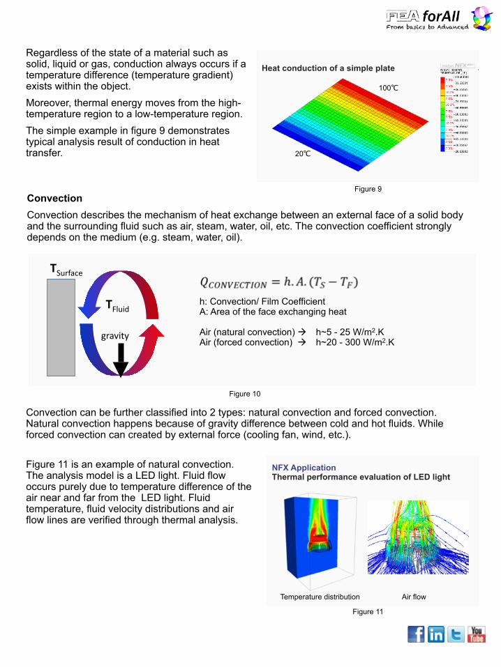
Regardless of the state of a material such as solid, liquid or gas, conduction always occurs if a temperature difference (temperature gradient) exists within the object. Moreover, thermal energy moves from the high-temperature region to a low-temperature region. The simple example in figure 9 demonstrates typical analysis result of conduction in heat transfer.
Heat conduction of a simple plate
Figure 9
100℃
20℃
Convection Convection describes the mechanism of heat exchange between an external face of a solid body and the surrounding fluid such as air, steam, water, oil, etc. The convection coefficient strongly depends on the medium (e.g. steam, water, oil).
gravity
TSurface
TFluid h: Convection/ Film Coefficient A: Area of the face exchanging heat
Air (natural convection) à h~5 - 25 W/m2.K Air (forced convection) à h~20 - 300 W/m2.K
Figure 10
Convection can be further classified into 2 types: natural convection and forced convection. Natural convection happens because of gravity difference between cold and hot fluids. While forced convection can created by external force (cooling fan, wind, etc.).
Figure 11 is an example of natural convection. The analysis model is a LED light. Fluid flow occurs purely due to temperature difference of the air near and far from the LED light. Fluid temperature, fluid velocity distributions and air flow lines are verified through thermal analysis.
NFX Application Thermal performance evaluation of LED light
Temperature distribution Air flow
Figure 11
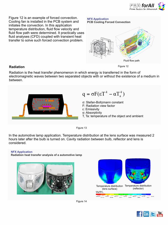
Figure 12 is an example of forced convection. Cooling fan is installed in the PCB system and initiates the convection. In this application temperature distribution, fluid flow velocity and fluid flow path were determined. It practically uses fluid analyses (CFD) coupled with transient heat transfer to solve such forced convection problem.
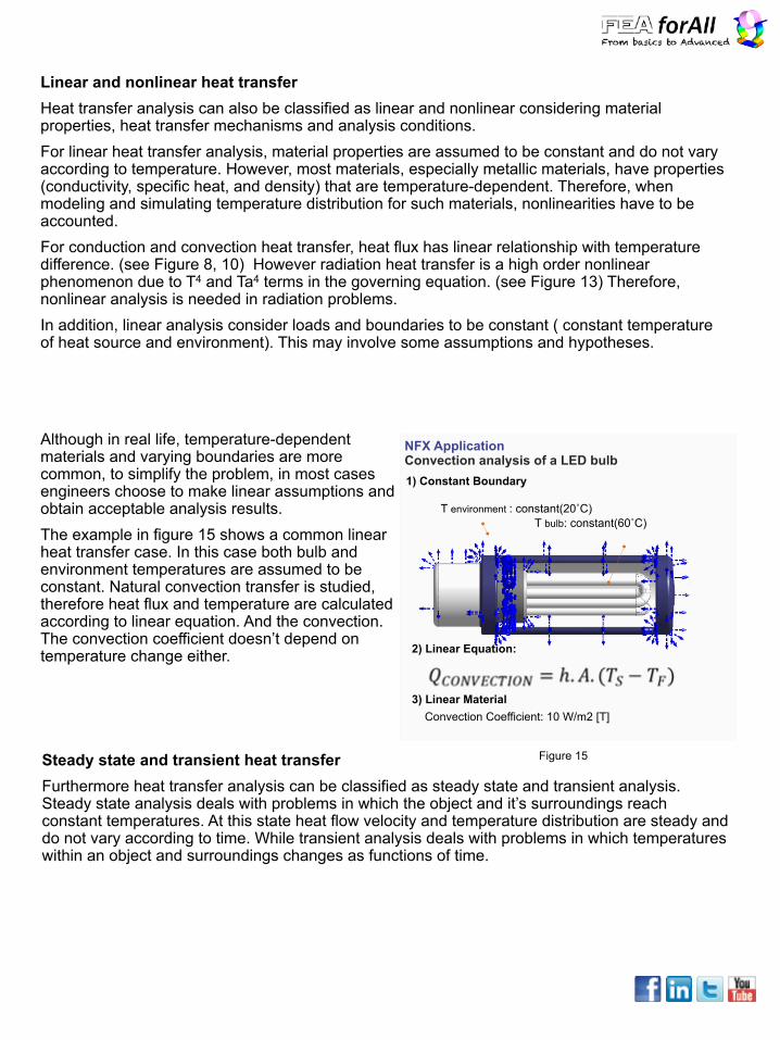
Radiation Radiation is the heat transfer phenomenon in which energy is transferred in the form of electromagnetic waves between two separated objects with or without the existence of a medium in between.
NFX Application PCB Cooling Forced Convection
Figure 12
Fluid flow path
)αTσF(εTq 4a
4 −= σ: Stefan-Boltzmann constant F: Radiation view factor ε: Emissivity α: Absorptivity T, Ta: temperature of the object and ambient
Figure 13
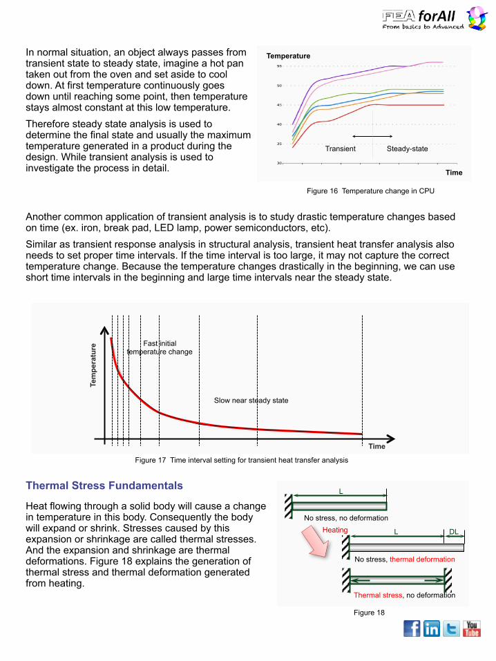
In the automotive lamp application. Temperature distribution at the lens surface was measured 2 hours later after the bulb is turned on. Cavity radiation between bulb, reflector and lens is considered.
NFX Application Radiation heat transfer analysis of a automotive lamp
Temperature distribution (lens surface)
Temperature distribution (reflector)
Figure 14
Linear and nonlinear heat transfer Heat transfer analysis can also be classified as linear and nonlinear considering material properties, heat transfer mechanisms and analysis conditions. For linear heat transfer analysis, material properties are assumed to be constant and do not vary according to temperature. However, most materials, especially metallic materials, have properties (conductivity, specific heat, and density) that are temperature-dependent. Therefore, when modeling and simulating temperature distribution for such materials, nonlinearities have to be accounted. For conduction and convection heat transfer, heat flux has linear relationship with temperature difference. (see Figure 8, 10) However radiation heat transfer is a high order nonlinear phenomenon due to T4 and Ta4 terms in the governing equation. (see Figure 13) Therefore, nonlinear analysis is needed in radiation problems. In addition, linear analysis consider loads and boundaries to be constant ( constant temperature of heat source and environment). This may involve some assumptions and hypotheses.
Although in real life, temperature-dependent materials and varying boundaries are more common, to simplify the problem, in most cases engineers choose to make linear assumptions and obtain acceptable analysis results. The example in figure 15 shows a common linear heat transfer case. In this case both bulb and environment temperatures are assumed to be constant. Natural convection transfer is studied, therefore heat flux and temperature are calculated according to linear equation. And the convection. The convection coefficient doesn’t depend on temperature change either.
NFX Application Convection analysis of a LED bulb
T bulb: constant(60˚C)T environment : constant(20˚C)
2) Linear Equation:
Convection Coefficient: 10 W/m2 [T]
1) Constant Boundary
3) Linear Material
Figure 15Steady state and transient heat transfer Furthermore heat transfer analysis can be classified as steady state and transient analysis. Steady state analysis deals with problems in which the object and it’s surroundings reach constant temperatures. At this state heat flow velocity and temperature distribution are steady and do not vary according to time. While transient analysis deals with problems in which temperatures within an object and surroundings changes as functions of time.
Steady-stateTransient
Time
TemperatureIn normal situation, an object always passes from transient state to steady state, imagine a hot pan taken out from the oven and set aside to cool down. At first temperature continuously goes down until reaching some point, then temperature stays almost constant at this low temperature. Therefore steady state analysis is used to determine the final state and usually the maximum temperature generated in a product during the design. While transient analysis is used to investigate the process in detail.
Figure 16 Temperature change in CPU
Another common application of transient analysis is to study drastic temperature changes based on time (ex. iron, break pad, LED lamp, power semiconductors, etc). Similar as transient response analysis in structural analysis, transient heat transfer analysis also needs to set proper time intervals. If the time interval is too large, it may not capture the correct temperature change. Because the temperature changes drastically in the beginning, we can use short time intervals in the beginning and large time intervals near the steady state.
Tem
pera
ture
Time
Fast initial temperature change
Slow near steady state
Figure 17 Time interval setting for transient heat transfer analysis
Heat flowing through a solid body will cause a change in temperature in this body. Consequently the body will expand or shrink. Stresses caused by this expansion or shrinkage are called thermal stresses. And the expansion and shrinkage are thermal deformations. Figure 18 explains the generation of thermal stress and thermal deformation generated from heating.
Thermal Stress Fundamentals
No stress, no deformation
L
L DL
No stress, thermal deformation
Thermal stress, no deformation
Heating
Figure 18
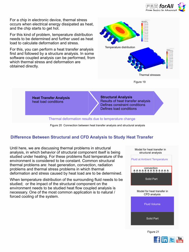
For a chip in electronic device, thermal stress occurs when electrical energy dissipated as heat, and the chip starts to get hot. For this kind of problem, temperature distribution needs to be determined and further used as heat load to calculate deformation and stress. For this, you can perform a heat transfer analysis first and followed by a structure analysis. In some software coupled analysis can be performed, from which thermal stress and deformation are obtained directly.
Figure 19
Temperature distribution
Thermal stresses
Thermal deformation results due to temperature change
Heat Transfer Analysis heat load conditions
Structural Analysis Results of heat transfer analysis Defines constraint conditions Defines load conditions
Figure 20 Connection between heat transfer analysis and structural analysis
Until here, we are discussing thermal problems in structural analysis, in which behavior of structural component itself is being studied under heating. For these problems fluid temperature of the environment is considered to be constant. Common structural thermal problems are: heat generation, convection, radiation problems and thermal stress problems in which thermal deformation and stress caused by heat load are to be determined. When temperature distribution of the surrounding fluid needs to be studied; or the impact of the structural component on the environment needs to be studied heat flow coupled analysis is necessary. One of the most common application is to natural / forced cooling of the system.
Difference Between Structural and CFD Analysis to Study Heat Transfer
Fluid Volume
Solid Part
Model for heat transfer in CFD analysis
Solid Part
Fluid at Ambient Temperature
convection
Model for heat transfer in structural analysis
Figure 21
We have well understood that FEA based verification tools are beneficial in many ways such as reducing prototyping cost, discovering problems in early stage of the design, gaining insights on thermal phenomenon which cannot be easily measured in physical tests, etc. However, choosing the right software is more crucial in order to solve the exact problem as well as to secure your project schedule and budget. To choose the right CAE software, especially to adopt the “simulation driven design” approach in a well established product design team, 4 major factors are to be considered here: 1)Solver capabilities 2)Easiness for modeling : CAD compatibility and integrated modeling tools 3)Speed and convenience of graphical output and reporting 4)Easiness to be learned and adopted in existing product design process
How to Choose Software for Thermal Analysis
Solver capabilities Considering the typical thermal problems introduced above, competent software should be able to analyze •Conduction, convection and radiation problems •Temperature-dependent material properties and boundary conditions ( nonlinear heat transfer) •Time-dependent thermal effects ( transient thermal analysis) •Thermal-structural coupled analysis to calculate thermal stress and deformation •Thermal-fluid coupled analysis to calculate natural / forced convection problems
Easiness for modeling New product are designed in CAD tools, many CAD tools are available on the market, and even in one team different CAD tools are usually being used. Therefore, CAD compatibility is another critical capacity to consider. Models directly taken from CAD designs are usually with excessive detailing. Especially electronic components, machine parts include many small holes, fillets, lines, faces which are not only unnecessary but also will lead to inefficient analysis. Common practice is to clean up the geometry model first before meshing and analyzing it.
Easiness to be learned and adopted Despite all the benefits that simulation can bring to product design, adopting “simulation driven design” approach in a well established team can be sometimes challenging. To fully leverage the capabilities of FEA simulation and create maximum values, design engineers need to learn FEA software as well as some specialized engineering knowledge. Sometime design engineers need to work together with analysis specialist in the team to complete a more complex analysis.
Convenient graphical output and reporting Thermal analysis calculates the temperature distribution and related thermal quantities in a system or component. Typical thermal quantities of interest are: •temperature distribution •amount of heat lost or gained •thermal gradient •thermal flux A good software provides result visualization in the most appropriate manner, as well provides tools to extract flexibly any result at any location of interest. Advanced requirements such as drawing value tables and graphs should also be satisfied.

Learn on FEA for All
Do you want to join my free « FEA Foundations » course?