theory of a directive optical leaky wave antenna ...apdsl.eng.uci.edu/recentjournals/theory of a...
TRANSCRIPT
JOURNAL OF LIGHTWAVE TECHNOLOGY, VOL. 32, NO. 9, MAY 1, 2014 1741
Theory of a Directive Optical Leaky Wave AntennaIntegrated into a Resonator and Enhancement
of Radiation ControlCaner Guclu, Student Member, IEEE, Salvatore Campione, Member, IEEE, Ozdal Boyraz, Senior Member, IEEE,
and Filippo Capolino, Senior Member, IEEE
Abstract—We provide for the first time the detailed study of theradiation performance of an optical leaky wave antenna (OLWA)integrated into a Fabry–Perot resonator. We show that the radi-ation pattern can be expressed as the one generated by the inter-ference of two leaky waves counter-propagating in the resonatorleading to a design procedure for achieving optimized broadsideradiation, i.e., normal to the waveguide axis. We thus report a re-alizable implementation of the OLWA made of semiconductor anddielectric regions. The theoretical modeling is supported by full-wave simulation results, which are found to be in good agreement.We aim to control the radiation intensity in the broadside direc-tion via excess carrier generation in the semiconductor regions. Weshow that the presence of the resonator can provide an effectiveway of enhancing the radiation level modulation, which reachesvalues as high as 13.5 dB, paving the way for novel promising ra-diation control capabilities that might allow the generation of veryfast optical switches, as an example.
Index Terms—Fabry–Perot resonator, optical leaky wave an-tenna (OLWA).
I. INTRODUCTION
O PTICAL leaky wave antennas (OLWAs) are optical an-tennas whose radiation principle is based on the excitation
of a leaky wave (LW) as a mode in a waveguide (WG).The subject of LWs has been largely studied in the past,
including their role in producing narrow beam radiation [1]–[8].A LW may be excited by placing a periodic set of perturbationson a slow wave structure, like an integrated WG, which hasan open aperture so that radiation can leak out. This concepthas been recently shown in [9] describing an OLWA made of adielectric WG comprising periodic silicon (Si) perturbations thatprovides very directive radiation at 1550 nm. Due to the presenceof the periodic perturbations, the overall LW that propagates inthe WG can be represented as the superposition of an infiniteset of Floquet spatial harmonics travelling with wavenumbers
kx,n = βx,n + iαx, with βx,n = βx,0 + 2πn/d (1)
Manuscript received November 5, 2013; revised January 10, 2014; acceptedJanuary 18, 2014. Date of publication January 30, 2014; date of current versionApril 10, 2014. This work was supported in part by the National Science Foun-dation under NSF Award # ECCS-1028727.
The authors are with the University of California, Irvine, CA 92697 USA(e-mail: [email protected]; [email protected]; [email protected]; [email protected]).
Color versions of one or more of the figures in this paper are available onlineat http://ieeexplore.ieee.org.
Digital Object Identifier 10.1109/JLT.2014.2304178
where we have assumed x to be the direction of propagation.Here, n is an index indicating the nth spatial harmonic, βx,n
is the phase constant of the nth harmonic, βx,0 is the funda-mental phase constant, d is the period of the perturbations. Allspatial harmonics have the same attenuation constant αx [anexp (−iωt) time harmonic dependence is implied]. If one of thespatial harmonics (usually the one with n = −1) is a fast wavewith respect to free space, having a phase velocity greater thanthe speed of light c (i.e., |βx,n | < k0 , with k0 = ω/c the free-space wavenumber), then it will radiate, and the overall mode(comprising all the harmonics) is said to be leaky.
Very narrow beam radiation is achieved when αx is relativelysmall with respect to k0 , making the LW slowly attenuatingwhile traveling along x. Interesting applications of such narrowbeam radiation may include the construction of novel highlydirective antennas and the development of future devices suchas fast optical switches and sensors. Moreover, very directivenear-infrared optical antennas with controlled radiation powerdensity and beam steering are of great need in applications likeplanar imaging [10] and LIDAR [11].
In the OLWA introduced in [9], as well as in other designs,as the one in [6] based on a thin film of patterned silver withperiod d excited by a subwavelength slot, the radiation comesfrom the n = −1 Floquet harmonic, and the period plays animportant role in determining the direction of radiation. Anotherimportant set of LW antennas is based on radiation coming fromthe n = 0 Floquet harmonic, i.e., the fundamental mode in thestructure. Some examples can be found in [12]–[21]. Directiveradiation can also be achieved at optical frequencies by excitingLWs in periodic arrays of plasmonic nanospheres as discussedin [22]–[24]. However, losses in metals usually prevent to havevery small attenuation constant αx and therefore very directivebeams.
The kind of LW antennas relevant for this paper is based onthe excitation of the n = −1 Floquet spatial harmonic. Since thisis the only harmonic contributing to radiation, we will denotethe wavenumber of the LW kLW = βLW + iαLW ≡ kx,−1 as in(1). As a general remark, any LW antenna of the two kinds(i.e., based on either the n = 0 or the n = −1 harmonic) justdescribed here radiates because of the spatial harmonic in therange (−k0 , k0), regardless of the index definition, along thedirection θLW provided by the formula
sin θLW = βLW /k0 . (2)
0733-8724 © 2014 IEEE. Personal use is permitted, but republication/redistribution requires IEEE permission.See http://www.ieee.org/publications standards/publications/rights/index.html for more information.
1742 JOURNAL OF LIGHTWAVE TECHNOLOGY, VOL. 32, NO. 9, MAY 1, 2014
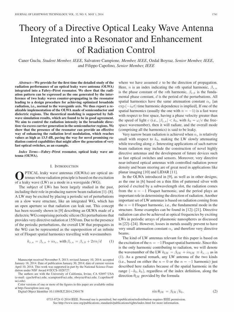
Fig. 1. Illustration of an OLWA embedded into a Fabry–Perot resonator. Thelengths D1 and D2 need to be carefully determined using LW theory, in such away that the two LWs traveling in opposite directions in the leaky WG producebeams with constructive interference.
Therefore, the theory developed in Section II applies to anyof the two kinds of LW antennas just described, since it dealsonly with the wavenumber of the radiating harmonic, regardlessof its index.
This paper develops the theory describing the radiation ofan OLWA integrated into a Fabry-Perot resonator (FPR) andillustrates approaches that can greatly enhance the control ofthe radiation level in the broadside direction, normal to the WGaxis. For demonstration purposes, we focus on the two dimen-sional (2-D) model (invariant along y) of the antenna reportedin Fig. 1, because the agreement between 2-D and 3-D calcula-tions for an isolated OLWA has been previously shown in [9].The OLWA under analysis comprises Si regions whose refrac-tive index and absorption is tunable via electronic or opticalexcess carrier generation. Note that in [9] silicon perturbationswere small thus enabling very fast control. Therefore the OLWAhere analyzed is a good platform for optical antennas with beamcontrol [25], [26]. We prove that the OLWA integration into theFPR enhances the radiation and provides electronic tunabilityas high as 13.5 dB by using carrier injection.
The organization of this paper is as follows. We explain theradiation properties of the OLWA inside the FPR and for thefirst time provide a simple physical interpretation and designguidelines based on LW theory in Section II. We then illustratein Section III a realistic design, using results from full-wavesimulations (finite element method in the frequency domain,COMSOL Multiphysics) in good agreement with theoreticalanalytical predictions. This section also includes analysis of theradiation control via carrier injection into the semiconductorregions within the radiating section of the antenna.
II. THEORY
We provide in this section the theoretical model of an OLWAembedded inside a FPR, depicted in Fig. 1. Within the two highlyreflective mirrors of the FPR lies a WG divided into three re-gions. The central leaky region (i.e., the OLWA) of length L(centered in the coordinate system along the x direction) pro-vides the directive radiation. On either side of the leaky regionthere are non-radiating regions of lengths D1 and D2 that deter-mine the FPR resonance condition as described in the following.We assume that the antenna is surrounded by a homogeneousmaterial with refractive index nh and wavenumber k = nhk0 .
The wavenumbers in the non-radiating WGs and in theleaky one are denoted as kWG and kLW , respectively, with
kLW = βLW + iαLW . In the following, we make two assump-tions: (i) low attenuation constant αLW (with respect to k) alongthe LW section; (ii) negligible mode mismatch between theleaky and non-radiating WGs at the dashed black lines in Fig. 1.Both assumptions are verified through the use of full-wavesimulations.
Assuming that the WG is fed from the −x edge throughmirror 1 (Fig. 1), the wave component propagating in the + xdirection that reaches the center of the leaky region (i.e., x =0 in Fig. 1) has electric field defined as E0 . Note however thatthe total field inside the resonators is due to multiple reflectionsfrom mirrors 1 and 2 (see Fig. 1). The wave propagating in the+ x direction upon one round trip inside the resonator is scaledby a complex factor
Δ = Γ1Γ2ei2kLW Lei2kW G (D1 +D2 ) (3)
where Γ1 and Γ2 are the reflection coefficients of mirrors 1 and2, respectively (possible mirror realizations will be discussed inthe next section). The total field propagating in the + x directioninside the leaky region is then given by the superposition of themultiple reflections as
E+ (x) = E0eikLW x
+∞∑
m=0
Δm (4)
with m an index indicating the number of round trips. Since|Δ| < 1, one can replace the summation in (4) with the factor
TFPR =1
1 − Δ(5)
which is an intrinsic parameter of the FPR that accounts for themultiple reflections inside the resonator itself. This parameterultimately determines the enhancement of the waves travelinginside the resonator. Accordingly, the LW propagating in the +x direction is described by
E+(x) = TFPRE0eikLW x . (6)
Similarly, the total field propagating in the −x direction canbe given in terms of E0 and
Γ0 = Γ2eikLW LeikW G 2D2 , (7)
the reflection coefficient towards the + x direction referred tothe center x = 0, as
E− (x) = TFPRΓ0E0e−ikLW x . (8)
Equations (6) and (8) are valid for x between −L/2 and+L/2, where the waves are leaky. Each LW will provide farfield beams that depend on the LW wavenumber kLW , as well ason the resonator parameter TFPR (large at the FPR resonance),which modulates the magnitude of the far field. By using theequivalent aperture technique [6], [9], [27] over the contourfrom where we assume radiation is occurring (e.g., here definedby the red dashed line in Fig. 1), the far zone fields due to theleaky waves propagating in the ±x directions are respectivelyfound as
E+FF (ρ, θ) = E0TFPRF+ (θ) Φ(ρ)
E−FF (ρ, θ) = Γ0E0TFPRF− (θ)Φ(ρ), (9)

GUCLU et al.: THEORY OF A DIRECTIVE OPTICAL LEAKY WAVE ANTENNA 1743
where Φ(ρ) =√
kLe−iπ/4eikρ/ (2πρ)1/2 and ρ is the distancefrom the antenna center on the xz plane. The individual LW farfield patterns are given as
F± (θ) = cos θsinψ± (θ)
ψ± (θ), (10)
with
ψ± (θ) = (k sin θ ∓ kLW ) L/2. (11)
Here θ is the angle with respect to the z-axis that can assumepositive or negative values, moreover, F+ (θ) and F− (θ) aresymmetric of each other with respect to θ = 0◦, i.e., F+ (θ) =F− (−θ). The total far field pattern is then given by
FT (θ) = F+ (θ) + Γ0F− (θ) . (12)
where the total field takes the form
ETFF (ρ, θ) = E0TFPRFT (θ) Φ(ρ) (13)
In particular, the far-field radiation is determined by the fol-lowing conditions/parameters: (i) the interference of LW radia-tion from counter propagating LWs that is highly dependent onΓ0 ; (ii) the quality factor of the resonator, intimately related toTFPR ; (iii) the LW wavenumber kLW (both real and imaginaryparts). These mechanisms are analytically governed by equa-tions (9) and (12). The superposition of the far field beams (F+
and Γ0F−), thus the field pattern of the antenna, is strongly
dependent on the phase and magnitude difference as a functionof Γ0 between the waves in opposite directions. Moreover thefield strength can be greatly controlled via the resonance termTFPR .
A. Tailoring the Total Radiation Pattern
As mentioned briefly in the introduction, following (2), theradiated beams due to the leaky-waves E± point to±θLW whereθLW ≈ sin−1 (βLW /k). As long as |βLW | � k, the approxima-tion θLW ≈ βLW /k can be applied (which also corresponds tohaving the beam close to the broadside direction).
We analyze the situation for which the main beams of F+
and Γ0F− are close to the broadside direction. The difference
between the phase of F+ and Γ0F−, say Δφ (θ) = ∠F+ (θ) −
∠ [Γ0F− (θ)], determines whether the two fields interfere con-
structively or destructively at the direction θ. According to (12),the phase Δφ (θ) can be tuned with the phase of Γ0 by properlydesigning D2 [see (7)], and thus one can obtain constructive in-terference at a certain angle θ. Once the constructive interferenceis achieved, the superposition of the far field radiation from thetwo LWs around the broadside direction will strongly depend onthe magnitude of Γ0 . We aim to superpose the two beams con-structively in the broadside direction, in order to maximize thebroadside radiation. Note that at broadside (θ = 0◦) F+ andF− are in phase since ∠F+ (θ = 0◦) = ∠F− (θ = 0◦) = 0◦
from (10) and (11). Therefore the constructive superpositionof F+ and Γ0F
− at the direction θ = 0◦ (thus maximizingthe magnitude of FT at broadside) is guaranteed by setting∠Γ0 = ∠F+ (0) − ∠F− (0) = 0◦. In order to visualize the su-perposed beams F+ and Γ0F
−, in Fig. 2 we provide the radi-
Fig. 2. Sketch of the far field beams due to the two leaky waves propagatingin the resonator.
ation level diagram of two beams due to the two leaky waveswhose maxima occur at ±θLW .
We define F±max = max (|F±|), hence at broadside the levels
of the patterns are reduced by a factor∣∣F+
θ=0◦
∣∣F+
max=
∣∣Γ0F−θ=0◦
∣∣|Γ0 |F−
max=
∣∣sinc( 1
2 LkLW)∣∣
sinhc( 1
2 LαLW) (14)
where sinc (x) = sin (x) /x and sinhc (x) = sinh (x) /x;moreover, sinc (iz) = sinhc (z) [the derivation of (14) is re-ported in the Appendix]. Assuming that the two beams are inphase at broadside, the total far field radiation level at broadsideis given by∣∣FT
θ=0◦∣∣ Δ= AF+
max =∣∣F+
θ=0◦
∣∣+∣∣Γ0F
−θ=0◦
∣∣=∣∣F+
θ=0◦
∣∣ [1 + |Γ0 |] ,(15)
where from (10) F−θ=0◦ = F+
θ=0◦ , and A is a real number deter-mined as
AΔ=
FTθ=0◦
F+max
=
∣∣sinc( 1
2 LkLW)∣∣
sinhc( 1
2 LαLW)
[1 + |Γ2 | e−αLW L
]. (16)
Therefore, the value of A is the measure of the maximumachievable broadside far field level upon superposition of thebeams. Depending on the pointing directions (±θLW ) and thedirectivities of the individual beams, the broadside radiation in-tensity of the total field can be stronger or weaker than thatof the individual beams. Here we aim at the determination ofa condition for having the broadside far field upon superposi-tion that bears a larger radiation level than the maxima of theindividual beams. This is achieved by imposing the conditionAF+
max > F+max , which guarantees that the two superposed LW
beams provide a field in the broadside direction stronger thanF+
max . In turn, this condition can be simply rewritten as A > 1.We rearrange (16) by using two parameters: the quality factorof the leaky WG
Q =βLW
2αLW, (17)
and the electrical length Lλ = L/λLW , where λLW = 2π/βLWis the LW wavelength. The condition in (16) is then expressedas
A =
∣∣∣sinc(πLλ
(1 + i 1
2Q
))∣∣∣
sinhc(π Lλ
2Q
)[1 + |Γ2 | e−π
L λQ
]> 1. (18)
Interestingly, the condition for increased broadside radiationin (18) has no dependence on the surrounding medium param-eters, showing that any proper physical implementation of the

1744 JOURNAL OF LIGHTWAVE TECHNOLOGY, VOL. 32, NO. 9, MAY 1, 2014
Fig. 3. The design parameter A versus Lλ for various Q ratios. When A >1 the total radiated field in the broadside direction has a larger magnitude thanthe radiated beam due to E+ in θLW direction.
Fig. 4. Two illustrative examples with (a) L = 0.5λLW (A>1) and (b) L =0.6λLW (A<1) where for both βLW = 0.05k0 , αLW = 0.1βLW , nh = 1,and |Γ2 | = 1.
device would allow for single beaming in the broadside direc-tion. In Fig. 3 we plot the design parameter A versus Lλ forvarious Q with the assumption |Γ2 | = 1. For very high Q, (neg-ligibly small αLW /βLW , thus |Γ0 | ≈ 1), the limiting conditionA = 1 occurs when Lλ ≈ 0.6 which corresponds to the caseF±
θ=0◦ = 0.5F±max , and FT
θ=0◦ = F±max . When Q is decreased
(for a certain βLW and λLW ), the maximum length of the an-tenna satisfying the condition A > 1 gets smaller. The mainmechanism that keeps A > 1 for constant kLW , i.e., followingone of the curves in Fig. 3, is a combination of the two factorsrealized with smaller L: (i) widening of the beams (with lowerdirectivity, F±
θ=0◦/F±max gets closer to 1); (ii) increase of |Γ0 |
(the level of Γ0F−θ=0◦ in Fig. 2 gets closer to the level of F+
θ=0◦).However a length L larger than the host wavelength is desir-able for achieving higher directivity (longer radiating aperture).These two conditions enforce a trade-off on the length of theleaky region L of the antenna in Fig. 1. Briefly, for our designpurposes the length of the leaky WG inside the FPR cannot bearbitrarily long for two reasons: (i) the directivity of the individ-ual beams shall not be too high because it may in turn preventthe formation of a single beam upon superposition; (ii) the re-flection coefficient |Γ0 | = |Γ2 | e−αLW L should be large enoughsuch that the levels of the beams Γ0F
− and F+ are comparable.Note that (ii) is also necessary for achieving a high quality factorin the FPR.
To provide proof of the condition in (18), two illustrativeexamples are reported in Fig. 4 having LW parameters βLW =0.05k0 , Q = 5, and |Γ2 | = 1. The first example [Fig. 4(a)] hasLλ = 0.5 for which A > 1 [green curve in Fig. 3, satisfying(18)] whereas the second one [Fig. 4(b)] has Lλ = 0.6 for whichA < 1 (green curve in Fig. 3). Fig. 4 includes the plots ofthe two individual beams |F+ | and |Γ0F
−| due to the waves
Fig. 5. |TFPR |2 plots varying design parameters. Dotted-dashed lines indicatethe locus of the peak of |TFPR |2 , denoted as |TFPR |2m ax .
E±, the total radiated field pattern∣∣FT
∣∣ when ∠Γ0 = 0◦, and∣∣FT∣∣max = |F+ | + |Γ0F
−|which is the locus of maximum pat-tern achievable for any direction θ (by assuming ∠Γ0 to be tunedaccordingly).
When (18) is not satisfied [see Fig. 4(b)], the radiation levelin the broadside direction is lower than the forward beam signif-icantly, whereas we observe a unified beam closer to the broad-side direction than the individual beams when (18) is satisfied[see Fig. 4(a)].
B. Resonance Control of the Fabry–Perot Resonator
The OLWA developed in [9] had small silicon perturbationsthat, despite being suitable for ultra fast tunability, was howevernot able to deliver significant radiation control. Instead, the in-tegration of a LW antenna inside a resonator has the advantageof controlling the radiation level by small parameter variations.Here we report the resonance behavior depending on the phys-ical dimensions and analyze the effect of small changes in theLW wavenumber kLW , a powerful mean of controlling the radi-ation level through the variation of the dielectric constant of theWG material by electrical or optical control. The enhancementof the intensity in far field due to the resonator is proportionalto |TFPR |2 according to (9).
The resonance occurs when the denominator of (5) is mini-mized in magnitude; therefore, the condition of resonance, i.e.,the maxima of |TFPR |2 , occurs when
∠Γ1 + ∠Γ2 + βLW 2L + kWG2D = 2qπ, (19)
where q is an integer. Eq. (19) inherently implies that the reso-nance has a periodic dependency on L and D with the periodsλWG/2 and λLW /2. Then, the maxima of |TFPR |2 for a certainset of Γ1 ,Γ2 , and αLW stay on a curve given by |TFPR |2max =1/
(1 −
∣∣Γ1Γ2e−αLW 2L
∣∣)2for any D, k‘WG , and βLW . In other
words, the variations in kWG , βLW and D can change the FPRresonant length while the peak of |TFPR |2 stays on the aforemen-tioned locus. In the remaining part of this section, we assume|Γ1Γ2 | = 1 and kWGD = kWG (D1 + D2) = 2mπ where m isan integer. The latter is done because |TFPR |2 depends on theelectrical length kWGD which is repetitive in 2π modulus forvarying physical length D and here we investigate the impact ofthe variations of kWG on |TFPR |2 for a given electrical lengthof the non perturbed WG length D. In Fig. 5(a) the parameter|TFPR |2 (solid lines) and the locus |TFPR |2max (dashed-dotted
GUCLU et al.: THEORY OF A DIRECTIVE OPTICAL LEAKY WAVE ANTENNA 1745
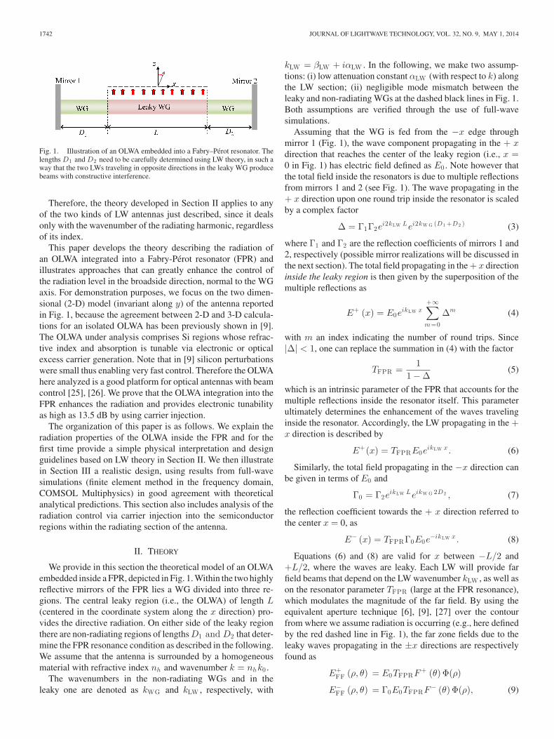
Fig. 6. The perturbed silicon waveguide design of the OLWA in FPR.
lines) are reported versus L/λ0 varying the attenuation constantαLW and the wave number βLW inside the radiating WG.
In Fig. 5(a), on one hand, one can observe that whenαLW is increased from 0.005k0 to 0.01k0 , assuming βLW =0.05k0 , |TFPR |2max decreases due to the decrease in the qual-ity factor of the resonance. This also shows that the control ofαLW can provide wide range of tunability of the radiation levelthrough the variation of |TFPR |2 . On the other hand, however,the increase in αLW induces a significant decrease in the rangeof control and the level of |TFPR |2 as the length of the radiatingsection is increased. In Fig. 5(b), we demonstrate the effect ofβLW , when αLW = 0.005k0 . It is clear that for specific lengthsL, |TFPR |2 can be effectively controlled by tuning βLW , sincethe resonance condition strongly depends on βLW . In summary,the length of the leaky-wave section L and the length of thenon-leaky WG on the mirror 2 side D2 have great importancein tailoring the radiation pattern. Moreover, D1 provides theflexibility to tune the resonance of the FPR for fixed L and D2 .Finally, the variations in kLW can push the LW antenna out ofresonance and thus alter the radiation level effectively as can beinferred from Fig. 5.
III. DESIGN OF OLWA IN FPR BASED
ON A SILICON WAVEGUIDE
In this section, we report the design of an OLWA inside aFPR that follows the principles explained in the previous sec-tion. We aim to enhance radiation level control thanks to theresonator by modifying the wavenumber of the guided leakymode. Silicon is thus chosen as the WG material, because itsrefractive index can be modified by generating excess carriers(electrons/holes) through electronic injection or optical excita-tion (a detailed analysis can be found in [26]). The design, whichis depicted in Fig. 6, utilizes a silicon (Si, with refractive indexnSi = 3.48) WG (with a height hWG = 0.7 μm), sandwichedbetween two silica glass domains (SiO2 , each with a heighthSiO2 = 5 μm and nSiO2 = 1.45) which hosts a mode withwavenumber kWG ≈ 3.36k0 (λWG ≈ 461.2 nm) at 193.4 THz(λ0 = 1550 nm). The structure is invariant along the y direction(thus 2-D), and the WG is positioned along the x-axis. In a 3-Dimplementation of the proposed antenna concept, a similar de-sign procedure to the one demonstrated in the following can beapplied. For proof-of-concept purposes based on simulations,the FPR is simply realized via two silver mirrors of thicknesses10 and 150 nm (Γ1 = 0.634∠ − 124◦,Γ2 = 0.994∠ − 148◦,retrieved via full wave simulation based on the finite element
method, COMSOL Multiphysics). Practical mirror implemen-tations may include approaches such as Bragg reflectors [28].Inside the FPR, the corrugated section of the silicon WG isturned into a leaky WG (similar to the illustration in Fig. 1)where the perturbations are periodic air-filled cavities with peri-odicity d = 460 nm and 100 nm × 100 nm cross-sectional di-mensions along the inner side of the top surface of the WG (seeFig. 6). In the following we assume that the antenna radiatesinto a homogeneous SiO2 environment (nh = nSiO2 ).
As mentioned in the introduction, the LW that propagatesin the WG pertains to the n = −1 Floquet spatial harmonictraveling in the periodically perturbed WG with wavenum-ber kLW = βLW + iαLW , with βLW = βx,0 − 2π/d as in (1)and αLW is the attenuation constant modeling the dissipativelosses—not present at the moment—and loss due to the LWradiation of the −1 harmonic. Note that the materials involved(Si and SiO2) have negligibly small loss at 1550 nm in com-parison to the radiation losses due to the LW radiation inducedby perturbations; therefore the non-perturbed WG is consid-ered lossless when no excess carriers are excited at the fre-quency of operation. This is a good approximation becauseradiation dominates the loss mechanisms in the proposed struc-ture. Moreover, the fundamental phase constant of the perturbedWG is βx,0 ≈ βWG = 2π/λWG , provided that the perturba-tions are small, as in our design. Following what is specifiedin Section I Eq. (2), the far-field beam radiates in the direc-tion θLW = sin−1 [βLW / (nhk0)]; this in turn means that theradiation close to the broadside direction can be guaranteedby setting βLW � nhk0 . In addition, the superposition of thetwo radiated beams provided by the two counter propagatingleaky waves forms a beam almost in the broadside direction asexplained in Section II-A. The condition βLW � nhk0 can beachieved by fixing the period d close to the fundamental mode’swavelength λWG , i.e., βLW ≈ βx,0 − 2π/λWG � nhk0 . In thisway we obtain βLW / (nhk0) ≈ −0.028 and αLW � βLW , re-trieved via full wave simulations of a 200-element long iso-lated OLWA when no excess carriers are generated. Note that,in practical implementations, as long as the perturbations aresmall (to guarantee small αLW ) and periodic (to guarantee theexcitation of the radiating spatial harmonic) the design is robustto fabrication tolerances. In particular, if we increased the sizeof the perturbations; the scattering effect, and thus the radia-tion, would lead to a higher attenuation constant. This in turnwould limit the quality factor of the FPR, degrading the degreeof modulation of the signal through injection of carriers in Si.The designed OLWA inside the FPR, illustrated in Fig. 6, hasN = 13 perturbations (the length of the leaky section is thusL = Nd). On one hand, in general, the shorter the radiatingsection is (with a fewer number of perturbations), the sharperthe FPR resonance is (via larger |TFPR |max ), and the larger thecontrol of the radiation level via carrier modulation is. On theother hand, a shorter radiating section yields smaller far-fielddirectivity. The trade-off between the directivity and the radia-tion level control is to be decided upon the application. Thus,here, we provide an example representative of the performanceof the OLWA in FPR device. The designed antenna is a 1-portsystem fed from one side, and due to the large thickness of

1746 JOURNAL OF LIGHTWAVE TECHNOLOGY, VOL. 32, NO. 9, MAY 1, 2014
Fig. 7. (a) Magnitude of the input reflection coefficient S11 of the antennavarying a pair of physical dimensions, D1 and D2 , represented by the residualphase shifts ξ1 and ξ2 , is plotted as a 2-dimensional color map, when nSi =3.48 (no excess carriers, Ne = Nh = 0 cm−3 ). (b) The broadside gain of theantenna, normalized by the maximum value of the cases reported in this plot forthe same set of parameters in (a).
Mirror 2 (Γ2 = 0.994∠ − 148◦) no signal propagates furtheralong the WG past the FPR region. Moreover, along the non-radiating sections of the WG, the mode is a purely guided mode(no attenuation mechanism is present) and the impact of thelengths D1 andD2 will be periodic with respect to the guidedwavelength λWG . Therefore these sections with lengths D1 andD2 will be referred as the residual phase shift (in modulo 360◦)the wave acquires and they are denoted by ξ1 and ξ2 , respectively[where ξ1,2 = mod360◦
(∠eikW G D1 , 2
)].
First we assess the antenna performance when no excess car-riers are present in Si. In Fig. 7(a) we show the magnitude ofthe reflection coefficient, |S11 |, at the input port for the struc-ture described above varying ξ1 and ξ2 (i.e., the lengths of thenon-leaky WG sections inside the FPR) from 0◦ to 270◦ with9.75◦ steps (corresponding to 12.5 nm increments in physicallength). It is observed from Fig. 7(a) that the minima of |S11 | lie
on a line which is roughly a constant ξΔ= ξ1 + ξ2 locus (black
dashed lines); moreover, |S11 | values exhibit periodicity withrespect to ξ, with a period around 180◦ (almost correspondingto a length of 0.5λWG ). This is in agreement with the conclu-sions provided in the previous section that the resonance of theFPR can be tuned by changing D [see (4)]. Then, we plot inFig. 7(b) the broadside (θ = 0◦) gain of the antenna (which doesnot account for the input mismatch) normalized by the maxi-mum gain among the reported (ξ1 , ξ2) pairs, for the same setof ξ1 and ξ2 as in Fig. 7(a). The broadside gain exhibits a peri-odic dependence on ξ2 with dips nearly every 180◦ (i.e., about0.5λWG ), which was inferred as a result of (7) where Γ0 is afunction of D2 but not D1 . The results in Fig. 7(a) and (b) are adirect proof that the resonance and the broadside gain level canbe controlled by properly adjusting the physical dimensions D1and D2 .
To assess the effect of free carriers and understand potentialelectronic tunability, the Drude model for the Si refractive indexis adopted into the simulations. In particular we assume theradiating section with length L of the Si WG inside the FPRinclude free carriers with density of Ne and Nh for electronsand holes, respectively. The refractive index change dependingon the density of excess electrons and holes can be calculatedas done in [29], [30]. We assume that excess electrons andholes with extreme concentrations of Ne = Nh = 1019 cm−3
Fig. 8. (a) Magnitude of the input reflection coefficient S11 of the antennaversus ξ1 and ξ2 is plotted as a 2-dimensional color map, when nSi ≈ 3.458 +i0.004 (in presence of excess carriers, Ne = Nh = 1019 cm−3 ). (b) The broadside gain of the antenna, normalized by the maximum gain for the same set ofparameters in (a).
Fig. 9. (a) The variation in input reflection |S11 | and (b) the variation in thebroadside far field upon generation of excess carriers in Si inside the FPR.
are injected into the silicon. These excess carriers induce therefractive index of Si to become nSi ≈ 3.458 + i0.004, with adecreased real part (with respect to the nominal value of 3.48)and a non-zero imaginary part that accounts for dissipative losseswith respect to the case in Fig. 7(a) and (b). With this modifiedrefractive index of Si inside the radiating section, we reportagain the magnitude of the scattering parameter S11 in Fig. 8(a)and the broadside gain (normalized by the maximum gain inthe absence of excess carriers in Si) in Fig. 8(b), for the samesets of ξ1 and ξ2 as in Fig. 7(a) and (b). The dependence of theresonant behavior on ξ1 and ξ2 and the broadside gain level’sdependence on ξ2 are similar to the case without excess carriersin Si. However, the locus of the minima in the graphs |S11 |versus ξ1 and ξ2 shifts by 20◦, for example minima move fromξ1 + ξ2 ≈ 175◦ [Fig. 7(a)] to ξ1 + ξ2 ≈ 195◦ [see Fig. 8(a)],due to the change in nSi . A similar shift is also present in thegraphs of broadside gain where the locus of the broadside gainminima shifts, for example the minima move from ξ2 ≈ 175◦
[see Fig. 7(b)] to ξ2 ≈ 190◦ [see Fig. 8(b)] and the effect oflosses in Si upon the generation of excess carriers results in adecrease in the broadside gain.
For fixed values of ξ1 and ξ2 , the introduction of excesscarriers modifies the radiated field at a direction θ in two ways:(i) the input mismatch of the antenna is modified, and thusthe accepted power; (ii) the gain (and the far field pattern) ismodified according to the change of the phase of Γ0 . We providethe variation of the magnitude of the input reflection coefficient,|S11 |, in Fig. 9(a) computed as the difference of |S11 | (in dB)in the two cases of no excess carriers and presence of excess
GUCLU et al.: THEORY OF A DIRECTIVE OPTICAL LEAKY WAVE ANTENNA 1747
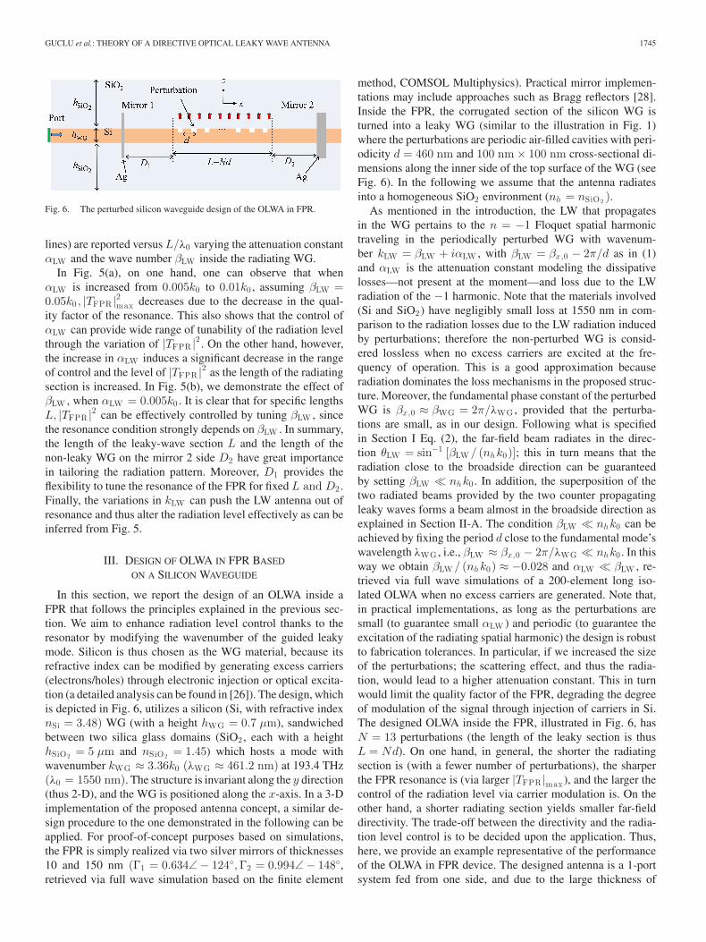
Fig. 10. (a) |S11 | versus wavelength where the vertical lines indicate theestimated Fabry-Perot resonance wavelengths, and (b) the radiation patternat 1550 nm normalized by the maximum of the two cases reported be-fore and after generation of excess carriers for the design parameters D1 =4250.8 nm, D2 = 4313.3 nm. The theoretical far-field pattern normalized toa maximum of unity is reported with grey dotted-dashed curve denoting theagreement between simulations and the analytical model.
carriers in Si. It is clear that varying the design pairs (ξ1 , ξ2)the reflection coefficient at the input port (thus the input power)varies between−15 dB and +6 dB, with very sudden variationsfor certain values of (ξ1 , ξ2). We also report the change in thebroadside far field (which takes the input mismatch into account)in Fig. 9(b) where variations down to −30 dB and up to +35 dBare observed for certain pairs (ξ1 , ξ2). Largest far-field variationsarise because radiation in either the presence or the absence ofexcess carriers presents a null in the broadside direction. In suchcases, a directive beam at broadside is not observed. A possiblegoal is to have OLWA designs with directive beams, achievedwhen dark red belts in Fig. 7(b) and Fig. 8(b) are overlappingwith yellow or dark blue regions in Fig. 9(a).
In order to analyze the frequency response of the designedantenna, we now provide in Fig. 10 the magnitude of the in-put reflection coefficient, |S11 |, versus wavelength and the farfield pattern of the antenna using the design parameters D1 =9λWG + 100 nm (ξ1 = 78◦) and D2 = 9λWG + 162.5 nm(ξ2 = 127◦) where λWG = 461.2 nm. Several resonances cor-responding to |S11 | dips are observed in the reported wave-length range, and the dips wavelength locations agree well withthe estimated wavelength of TFPR maxima (denoted by verticallines) by means of simple free spectral range formulas. One ob-serves that the input is not matched at 1550 nm (193.4 THz) forNe = Nh = 0 cm−3 , though it exhibits a minimum of −5.5 dBat 1555 nm (blue solid curve). On the other hand, the reso-nance wavelength shifts due to the induced change in Si re-fractive index and the matching is improved at 1550 nm whenthe concentration of electrons and holes is increased from 0 to1019 cm−3 leading to a −15 dB match (red dashed curve). Thisimprovement in matching also manifests itself in the radiatedfar field at broadside. We observe an increase of 5 dB in the
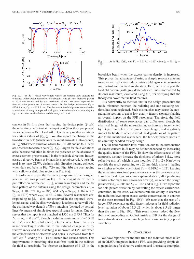
Fig. 11. As in Fig. 10(b), with Γ1 = 0.919∠− 142◦ when ξ1 = 70◦, ξ2 =109◦.
broadside beam when the excess carrier density is increased.This proves the advantage of using a sharply resonant antennatogether with refractive index control yielding to an input match-ing control and far field modulation. Here, we also report thefar-field pattern (with grey dotted-dashed lines, normalized byits own maximum) evaluated using (13) for verifying that thetheory can cover the far-field features.
It is noteworthy to mention that in the design procedure themode mismatch between the radiating and non-radiating sec-tions has been neglected. Such mismatches may cause the non-radiating sections to act as low-quality-factor resonators havingan overall impact on the FPR resonance. Therefore, the fielddistributions of some resonances can differ even though theelectrical length of the non-radiating sections are incrementedby integer multiples of the guided wavelength, and negativelyimpact far fields. In order to avoid the degradation of the patterndue to the mentioned resonances, the far-field pattern needs tobe carefully handled for any design.
The far field radiation level variation due to the introductionof excess carriers in Si may be further enhanced by increasingthe quality factor of the FPR. To show the effectiveness of thisapproach, we may increase the thickness of mirror 1 (i.e., morereflective mirror), which in turn modifies |Γ1 | in (3). Hereby weprovide the result pertaining to a 20 nm thick mirror 1 leadingto a higher reflection coefficient Γ1 = 0.919∠ − 142◦, keepingthe remaining structural parameters same as the previous cases.Based on the design procedure explained above, after producingsimilar color maps (not shown for brevity), we reach the designparameters ξ1 = 70◦ and ξ2 = 109◦ and in Fig. 11 we report thefar field pattern variation by controlling the excess carrier con-centration. In this case, we demonstrate the ability to decreasethe radiation level upon excess carrier concentration in contrastto the case reported in Fig. 10(b). We note that the use of alarger FPR resonator quality factor induces a far field radiationlevel variation of about 13.5 dB, which is about 8.5 dB largerthan the case in Fig. 10(b). This result shows indeed the flex-ibility of embedding an OLWA inside a FPR for the design ofinnovative devices that require large level variation (e.g., opticalswitches).
IV. CONCLUSION
We have reported for the first time the radiation mechanismof an OLWA integrated inside a FPR, also providing simple de-sign guidelines for directive emission and illustrative examples.

1748 JOURNAL OF LIGHTWAVE TECHNOLOGY, VOL. 32, NO. 9, MAY 1, 2014
Importantly, we have shown that the radiation at broadside canbe controlled effectively by the introduction of excess carriers inSilicon, and this enables the vision of innovative devices, such asfast optical switches or sensors. The integration into a resonatoris important to enhance tunability of radiation power levels.Moreover similar concepts can be implemented at microwaveand millimeter wave frequencies, with the design equations hereprovided.
APPENDIX: RETRIEVAL OF THE PARAMETERS
DESCRIBED IN (14)
Here we report the derivation steps of the expression re-ported in (14). Assume that the leaky waves of interest radiatevery close to the broadside direction, thus the approximationcos (θ) = 1 is applied in (10). We use a complex valued sincfunction in (10), and its maximum is given by
max [|sinc (x + iK)|] = |sinc (x + iK)|x=0 == sinc (iK) = sinhc (K) (20)
where K is a real constant and x is the real variable of thefunction. Thus the maxima of the patterns in (10) occur whenRe (k sin θ ∓ kLW ) = 0 where both |F±| possess the maximaF±
max = sinhc (αLW L/2). Moreover, the patterns in (10) pos-sess the same value at the broadside direction, θ = 0◦, asF±
θ=0 = sinc (∓kLW L/2). Finally, this leads to∣∣F±
θ=0
∣∣F±
max=
|sinc (kLW L/2)|sinhc (αLW L/2)
. (21)
REFERENCES
[1] A. A. Oliner, “Leaky-wave antennas,” in Antenna Engineering Handbook,R. C. Johnson, Ed. New York, NY, USA: McGraw Hill, 1993.
[2] P. Burghignoli, G. Lovat, F. Capolino, D. R. Jackson, and D. R. Wilton,“Modal propagation and excitation on a wire-medium slab,” IEEE Trans.Microw. Theory Techn., vol. 56, no. 5, pp. 1112–1124, May 2008.
[3] T. Tamir and A. A. Oliner, “Guided complex waves. I. Fields at an inter-face,” Proc. IEE, vol. 110, pp. 310–324324, 1963.
[4] T. Tamir and A. A. Oliner, “Guided complex waves. II. Relation to radia-tion patterns,” Proc. IEE, vol. 110, pp. 325–334334, 1963.
[5] P. Burghignoli, G. Lovat, F. Capolino, D. R. Jackson, and D. R. Wilton,“Enhancement of directivity by using metamaterial substrates,” in Appli-cations of Metamaterials, F. Capolino, Ed. Boca Raton, FL, USA: CRCPress, 2009, p. 19.
[6] D. R. Jackson and A. A. Oliner, “Leaky-wave antennas,” in ModernAntenna Handbook, C. A. Balanis, Ed. Hoboken, NJ, USA: Wiley,2008, pp. 325–367.
[7] D. R. Jackson, P. Burghignoli, G. Lovat, F. Capolino, J. Chen,D. R. Wilton, and A. A. Oliner, “The fundamental physics of directivebeaming at microwave and optical frequencies and the role of leakywaves,” Proc. IEEE, vol. 99, no. 10, pp. 1780–1805, Oct. 2011.
[8] D. R. Jackson, C. Caloz, and T. Itoh, “Leaky-wave antennas,” Proc. IEEE,vol. 100, no. 7, pp. 2194–2206, Jul. 2012.
[9] Q. Song, S. Campione, O. Boyraz, and F. Capolino, “Silicon-based opticalleaky wave antenna with narrow beam radiation,” Opt. Exp., vol. 19,pp. 8735–8749, 2011.
[10] Q. Song, F. Qian, E. K. Tien, I. Tomov, J. Meyer, X. Z. Sang, andO. Boyraz, “Imaging by silicon on insulator waveguides,” Appl. Phys.Lett., vol. 94, Jun. 2009.
[11] C. K. Toth, “R&D of mobile LIDAR mapping and future trends,” presentedat the ASPRS Annu. Conf., Baltimore, MD, USA, 2009.
[12] P. Baccarelli, P. Burghignoli, F. Frezza, A. Galli, P. Lampariello, G. Lovat,and S. Paulotto, “Effects of leaky-wave propagation in metamaterialgrounded slabs excited by a dipole source,” IEEE Trans. Microw. The-ory Techn., vol. 53, no. 1, pp. 32–44, Jan. 2005.
[13] K. C. Gupta, “Narrow-beam antennas using an artificial dielectric mediumwith permittivity less than unity,” Electron. Lett., vol. 7, pp. 16–18, 1971.
[14] I. Bahl and K. Gupta, “A leaky-wave antenna using an artificial dielectricmedium,” IEEE Trans. Antennas Propag., vol. AP-22, no. 1, pp. 119–122,Jan. 1974.
[15] S. Enoch, G. Tayeb, P. Sabouroux, N. Guerin, and P. Vincent, “A meta-material for directive emission,” Phys. Rev. Lett., vol. 89, Nov. 2002.
[16] P. Burghignoli, G. Lovat, F. Capolino, D. R. Jackson, and D. R. Wilton,“Directive leaky-wave radiation from a dipole source in a wire-mediumslab,” IEEE Trans. Antennas Propag., vol. 56, no. 5, pp. 1329–1339, May2008.
[17] D. R. Jackson and A. A. Oliner, “A leaky-wave analysis of the high-gainprinted antenna configuration,” IEEE Trans. Antennas Propag., vol. 36,no. 7, pp. 905–910, Jul. 1988.
[18] H. Y. Yang and N. G. Alexopoulos, “Gain enhancement methods forprinted-circuit antennas through multiple superstrates,” IEEE Trans. An-tennas Propag., vol. AP-35, no. 7, pp. 860–863, Jul. 1987.
[19] D. R. Jackson, A. A. Oliner, and A. Ip, “Leaky-wave propagation andradiation for a narrow-beam multiple-layer dielectric structure,” IEEETrans. Antennas Propag., vol. 41, no. 3, pp. 344–348, Mar. 1993.
[20] T. Akalin, J. Danglot, O. Vanbesien, and D. Lippens, “A highly directivedipole antenna embedded in a fabry-Perot type cavity,” IEEE Microw.Wireless Compon. Lett., vol. 12, no. 2, pp. 48–50, Feb. 2002.
[21] H. Ostner, J. Detlefsen, and D. R. Jackson, “Radiation from one-dimensional dielectric leaky-wave antennas,” IEEE Trans. AntennasPropag., vol. 43, no. 4, pp. 331–339, Apr. 1995.
[22] X. Liu and A. Alu, “Subwavelength leaky-wave optical nanoantennas:Directive radiation from linear arrays of plasmonic nanoparticles,” Phys.Rev. B, vol. 82, pp. 144305-1–144305-12, 2010.
[23] S. Campione, S. Steshenko, and F. Capolino, “Complex bound and leakymodes in chains of plasmonic nanospheres,” Opt. Exp., vol. 19, pp. 18345–18363, 2011.
[24] A. L. Fructos, S. Campione, F. Capolino, and F. Mesa, “Characterizationof complex plasmonic modes in two-dimensional periodic arrays of metalnanospheres,” J. Opt. Soc. Amer. B, vol. 28, pp. 1446–1458, 2011.
[25] K. Van Acoleyen, W. Bogaerts, J. Jagerska, N. Le Thomas, R. Houdre, andR. Baets, “Off-chip beam steering with a one-dimensional optical phasedarray on silicon-on-insulator,” Opt. Lett., vol. 34, pp. 1477–1479, May2009.
[26] S. Campione, C. Guclu, Q. Song, O. Boyraz, and F. Capolino, “An opticalleaky wave antenna with Si perturbations inside a resonator for enhancedoptical control of the radiation,” Opt. Exp., vol. 20, pp. 21305–21317,2012.
[27] D. R. Jackson, J. Chen, R. Qiang, F. Capolino, and A. A. Oliner, “Therole of leaky plasmon waves in the directive beaming of light through asubwavelength aperture,” Opt. Exp., vol. 16, pp. 21271–21281, Dec. 2008.
[28] S. Akiyama, F. J. Grawert, J. Liu, K. Wada, G. K. Celler, L. C. Kimerling,and F. X. Kaertner, “Fabrication of highly reflecting epitaxy-ready Si-SiO2 Bragg reflectors,” IEEE Photon. Technol. Lett., vol. 17, no. 7,pp. 1456–1458, Jul. 2005.
[29] O. Boyraz, X. Sang, E. Tien, Q. Song, F. Qian, and M. Akdas, “Siliconbased optical pulse shaping and characterization,” Proc. SPIE, vol. 7212,pp. 72120U-1–72120U-13, 2009.
[30] S. Manipatruni, L. Chen, and M. Lipson, “Ultra high bandwidth WDMusing silicon microring modulators,” Opt. Exp., vol. 18, pp. 16858–16867,2010.
Caner Guclu (S’10) received the B.S. and M.S. degrees in electrical engineer-ing from the Middle East Technical University (METU), Ankara, Turkey, in2008 and 2010, respectively. Since 2010, he has been working toward the Ph.D.degree at the University of California, Irvine, CA, USA.
From 2008 to 2010, he was a Research and Teaching Assistant with theDepartment of Electrical and Electronics Engineering at METU. In November2009, he worked at Centre Tecnologic de Telecomunicacions de Catalunya asa Visiting Researcher for a Short-Term Scientific Mission funded by COST(European Cooperation in Science and Technology) ASSIST. He was a VisitingScholar at the Center for Integrated Nanotechnologies, Sandia National Labora-tories, in Summer 2013. He has published more than ten peer-reviewed journalarticles, more than 20 conference papers, and a book chapter. His researchinterests include reflectarray design, optical leaky wave antennas, hyperbolicmetamaterials, and characterization and applications of plasmonic metamateri-als and nanostructures.
Mr. Guclu was a recipient of Research Fellowship from the Scientific andTechnical Research Council of Turkey (TUBITAK) from 2009 to 2010. He re-ceived the Student Travel Fellowship by the URSI National Committee for 2013and 2014.
GUCLU et al.: THEORY OF A DIRECTIVE OPTICAL LEAKY WAVE ANTENNA 1749
Salvatore Campione (S’08–M’09) received the Laurea triennale degree (cumlaude) and the Laurea Magistrale degree (cum laude) in electrical engineeringfrom Polytechnic of Turin, Turin, Italy, in 2007 and 2009, respectively, theM.S. degree in electrical engineering from the University of Illinois at Chicago,Chicago, IL, USA, in 2009, and the Ph.D. degree in electrical engineering fromthe University of California Irvine, Irvine, CA, USA, in 2013.
He is currently a Postdoctoral Appointee at Sandia National Laboratories,Albuquerque, NM, USA. He was a Visiting Scholar at the U.S. Army Charles M.Bowden Research Center, RDECOM, Redstone Arsenal, Huntsville, AL, USA,in 2012, and at the Center for Integrated Nanotechnologies, Sandia NationalLaboratories, Albuquerque, NM, USA, in 2012 and 2013. He has publishedmore than 20 peer-reviewed journal articles, more than 40 conference papers,and two book chapters. His research interests include metamaterials and their ap-plications, plasmonics in nanostructures, optical devices with super-resolution,and electromagnetics in general.
Dr. Campione is a member of the IEEE Photonics Society, The Interna-tional Society for Optical Engineers, and American Physical Society (APS). Hereceived Sigma Xi Grant-in-Aid of Research in 2011, two SPIE Scholarshipsin Optics and Photonics in 2011 and 2012, and the IEEE Photonics SocietyGraduate Student Fellowship in 2013. He has been selected as a 2013 MarconiSociety Paul Baran Young Scholar, recognizing his academic achievements andleadership in the field of communications and information science. He has alsobeen awarded several travel grants, including the Newport Spectra Physics Re-search Excellence Travel Award in 2011, granted by SPIE, and the FGSA TravelAward for Excellence in Graduate Research in 2012, granted by APS.
Ozdal Boyraz received the B.S. degree in electrical engineering from HacettepeUniversity, Ankara, Turkey, in 1993, and the M.S. and Ph.D. degrees in electricalengineering from the University of Michigan, Ann Arbor, MI, USA, 1997 and2001, respectively.
After graduation, he worked as R&D Engineer at Xtera Communications,Allen, TX, USA, for two years, and as a Postdoctoral Scholar at the Universityof California, Los Angeles. After completing the postdoctoral study, he joinedthe Electrical Engineering and Computer Science Departments at the Universityof California, Irvine, as an Assistant Professor in 2005. He currently serves as anAssociate Professor in the same department as well as in the Materials Scienceand Engineering program. His research areas include silicon based photonicdevices, nonlinear optical devices, optical communication systems, and opticalsignal processing.
Dr. Boyraz is a member of the Optical Society of America. He is a recipientof 2010 DARPA Young Faculty Award and 2005 IEICE Electronic Express BestPaper Award.
Filippo Capolino (S’94-M’97–SM’04) received the Laurea (cum laude) andPh.D. degrees in electrical engineering from the University of Florence,Florence, Italy, in 1993 and 1997, respectively.
He is currently an Associate Professor in the Department of Electrical En-gineering and Computer Science, University of California, Irvine, CA, USA.Previously, he was an Assistant Professor in the Department of InformationEngineering, University of Siena, Siena, Italy. From 1997 to 1999, he was aPostdoctoral Fellow with the Department of Aerospace and Mechanical Engi-neering, Boston University, Boston, MA, USA. From 2000 to 2001 and in 2006,he was a Research Assistant Visiting Professor with the Department of Elec-trical and Computer Engineering, University of Houston, Houston, TX, USA.His research interests include antennas, metamaterials and their applications,sensors in both microwave and optical ranges, wireless systems, chip-integratedantennas. He was the EU Coordinator of the EU Doctoral Programs on Meta-materials from 2004 to 2009.
Dr. Capolino is a member of the Optical Society of America and the Interna-tional Society for Optical Engineers. He received the R. W. P. King Prize PaperAward from the IEEE Antennas and Propagation Society for the Best Paper ofthe Year 2000, by an author under 36. From 2002 to 2008, he served as an As-sociate Editor for the IEEE TRANSACTIONS ON ANTENNAS AND PROPAGATION.He is the Editor of the Metamaterials Handbook (Boca Raton, FL, USA: CRCPress, 2009).